Embed Size (px)
Citation preview
Traveler Phase 1A Joint Review
6/20/2017
Preface
• Initial system design, implementation, verification, and flight testing has been conducted. As
of yet detailed data review is incomplete, and flight testing has been limited to initial monitor
force fights. Detailed monitor flight evaluations have yet to be performed. Initial preliminary
findings are being discussed in this package. They are not final.
• Lessons learned guidance is preliminary as well and attempts have been made to tailor them
to generic Multi-Monitor Run-Time Assurance (MMRTA). Guides are expected to be
developed once more detailed testing / analysis has been performed.
Outline
• Expandable Variable Autonomous Architecture (EVAA) Phase 1A Description
– Phase 1A Scope
– Hardware
– Software
• Findings from EVAA Phase 1A
– Requirements Development
– Design Development
– Test Approach
• Verification Testing
• Flight Test
• Standard Practice Review
– Review of ASTM standard practice
– Considerations for autonomous systems certification framework / approach
• Next Steps
– Now to 31 Aug 17
– Potential Later Phases
3

EVAA Phase 1A Description
Phase 1 / 1A Scope
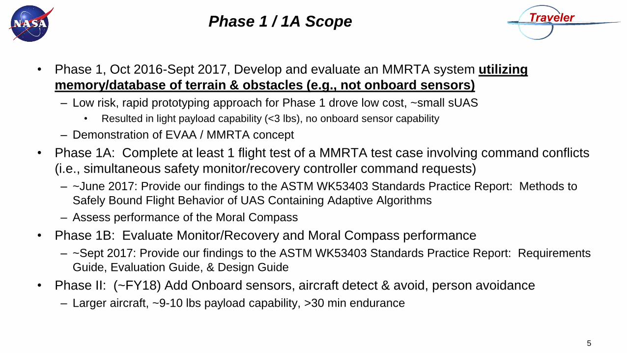
• Phase 1, Oct 2016-Sept 2017, Develop and evaluate an MMRTA system utilizing
memory/database of terrain & obstacles (e.g., not onboard sensors)
– Low risk, rapid prototyping approach for Phase 1 drove low cost, ~small sUAS
• Resulted in light payload capability (<3 lbs), no onboard sensor capability
– Demonstration of EVAA / MMRTA concept
• Phase 1A: Complete at least 1 flight test of a MMRTA test case involving command conflicts
(i.e., simultaneous safety monitor/recovery controller command requests)
– ~June 2017: Provide our findings to the ASTM WK53403 Standards Practice Report: Methods to
Safely Bound Flight Behavior of UAS Containing Adaptive Algorithms
– Assess performance of the Moral Compass
• Phase 1B: Evaluate Monitor/Recovery and Moral Compass performance
– ~Sept 2017: Provide our findings to the ASTM WK53403 Standards Practice Report: Requirements
Guide, Evaluation Guide, & Design Guide
• Phase II: (~FY18) Add Onboard sensors, aircraft detect & avoid, person avoidance
– Larger aircraft, ~9-10 lbs payload capability, >30 min endurance
5
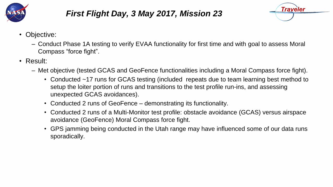
• Objective:
– Conduct Phase 1A testing to verify EVAA functionality for first time and with goal to assess Moral
Compass “force fight”.
• Result:
– Met objective (tested GCAS and GeoFence functionalities including a Moral Compass force fight).
• Conducted ~17 runs for GCAS testing (included repeats due to team learning best method to
setup the loiter portion of runs and transitions to the test profile run-ins, and assessing
unexpected GCAS avoidances).
• Conducted 2 runs of GeoFence – demonstrating its functionality.
• Conducted 2 runs of a Multi-Monitor test profile: obstacle avoidance (GCAS) versus airspace
avoidance (GeoFence) Moral Compass force fight.
• GPS jamming being conducted in the Utah range may have influenced some of our data runs
sporadically.
First Flight Day, 3 May 2017, Mission 23
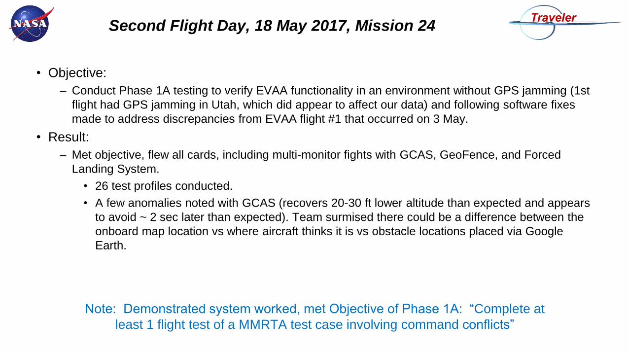
• Objective:
– Conduct Phase 1A testing to verify EVAA functionality in an environment without GPS jamming (1st
flight had GPS jamming in Utah, which did appear to affect our data) and following software fixes
made to address discrepancies from EVAA flight #1 that occurred on 3 May.
• Result:
– Met objective, flew all cards, including multi-monitor fights with GCAS, GeoFence, and Forced
Landing System.
• 26 test profiles conducted.
• A few anomalies noted with GCAS (recovers 20-30 ft lower altitude than expected and appears
to avoid ~ 2 sec later than expected). Team surmised there could be a difference between the
onboard map location vs where aircraft thinks it is vs obstacle locations placed via Google
Earth.
Note: Demonstrated system worked, met Objective of Phase 1A: “Complete at
least 1 flight test of a MMRTA test case involving command conflicts”
Second Flight Day, 18 May 2017, Mission 24
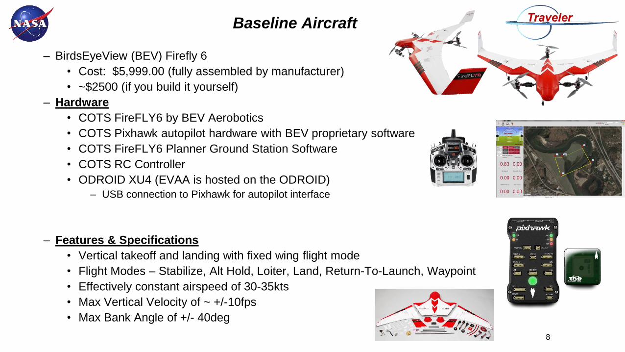
– BirdsEyeView (BEV) Firefly 6
• Cost: $5,999.00 (fully assembled by manufacturer)
• ~$2500 (if you build it yourself)
– Hardware
• COTS FireFLY6 by BEV Aerobotics
• COTS Pixhawk autopilot hardware with BEV proprietary software
• COTS FireFLY6 Planner Ground Station Software
• COTS RC Controller
• ODROID XU4 (EVAA is hosted on the ODROID)
– USB connection to Pixhawk for autopilot interface
– Features & Specifications
• Vertical takeoff and landing with fixed wing flight mode
• Flight Modes – Stabilize, Alt Hold, Loiter, Land, Return-To-Launch, Waypoint
• Effectively constant airspeed of 30-35kts
• Max Vertical Velocity of ~ +/-10fps
• Max Bank Angle of +/- 40deg
Baseline Aircraft
8
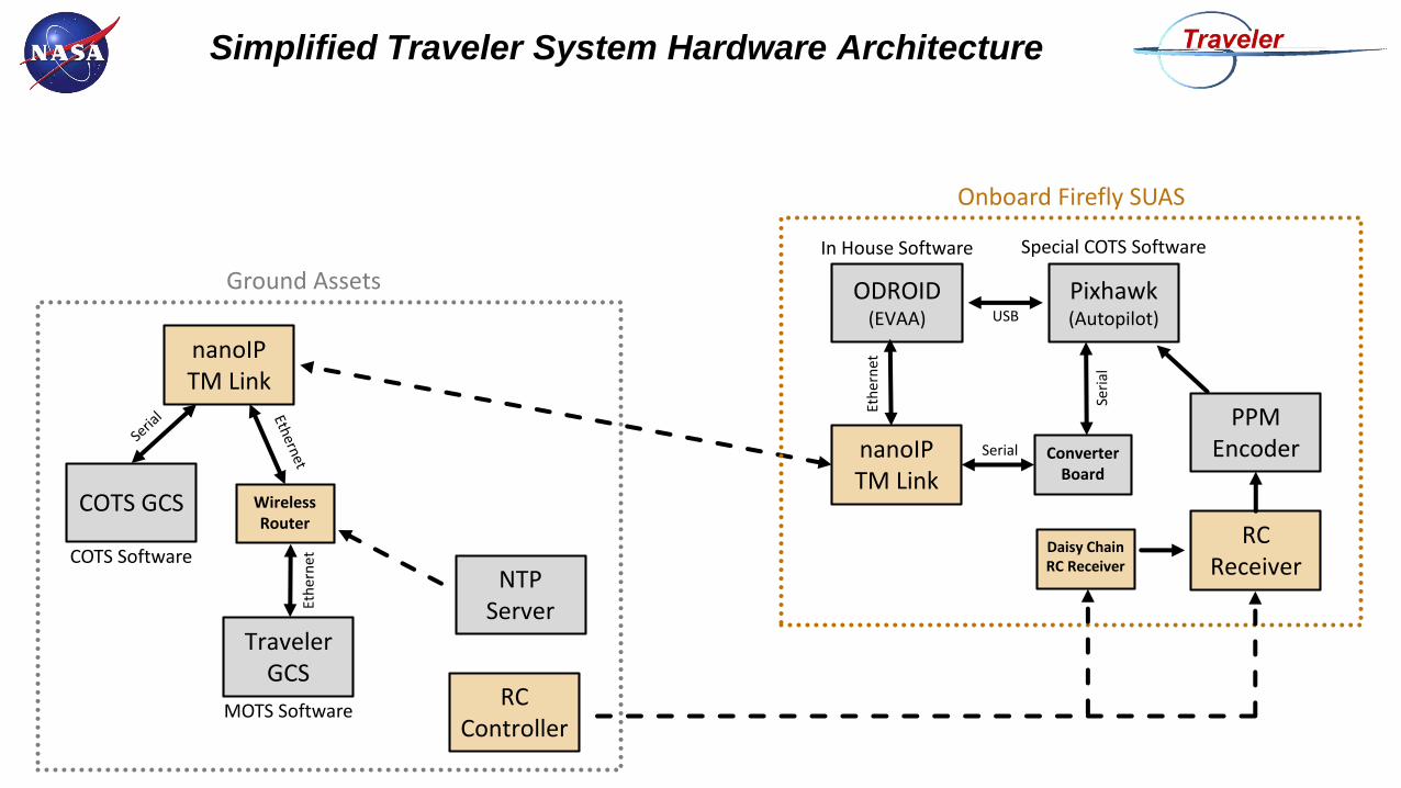
Simplified Traveler System Hardware Architecture
ODROID(EVAA)
Pixhawk(Autopilot)
nanoIPTM Link
nanoIPTM Link
COTS GCS
Traveler GCS
RC Controller
Onboard Firefly SUAS
Ground Assets
In House Software Special COTS Software
MOTS Software
COTS Software
Eth
ern
et
USB
RC Receiver
PPM Encoder
Daisy Chain RC Receiver
Wireless Router
Eth
ern
et
NTPServer
Converter Board
Serial
Seri
al
9
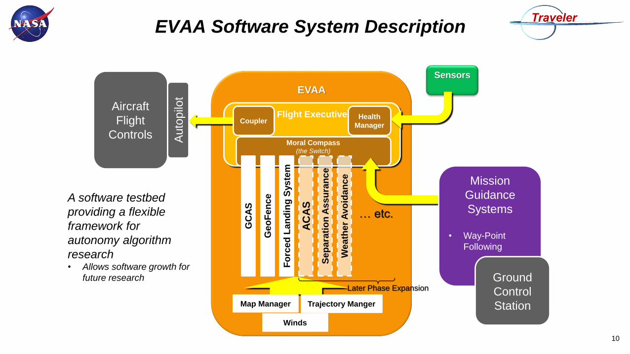
EVAA Software System Description
10
Aircraft
Flight
Controls Auto
pilo
t
EVAA
Flight Executive
Moral Compass(the Switch)
Health
Manager
Sensors
GC
AS
Ge
oF
en
ce
Fo
rce
d L
an
din
g S
ys
tem
AC
AS
Se
pa
rati
on
As
su
ran
ce
We
ath
er
Avo
ida
nc
e
… etc.
Later Phase Expansion
A software testbed
providing a flexible
framework for
autonomy algorithm
research• Allows software growth for
future research
Mission
Guidance
Systems
• Way-Point
Following
Ground
Control
Station
Coupler
Map Manager Trajectory Manger
Winds

RTA Input
Manager
(CVT) Veh
icle
Man
ag
em
en
t S
yste
m
Safety Monitors
(With Recovery
Maneuvers)
SensorsSensors
SensorsSensors RTA
Switch
Complex
Function
(Untrusted
System) Baseline Aircraft
RTA Trusted Functions
Untrusted Controllers
Legend
Sensors
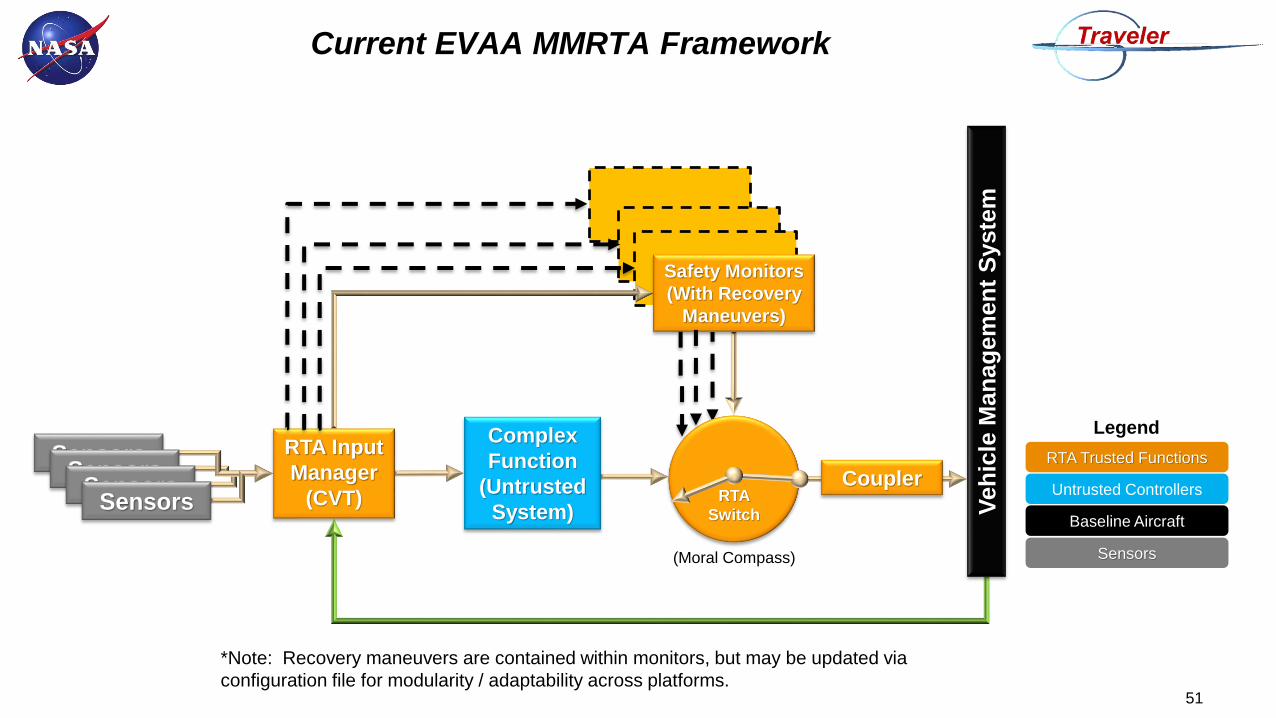
Current EVAA MMRTA Framework
11
Coupler
(Moral Compass)
*Note: Recovery maneuvers are contained within monitors, but may be updated via
configuration file for modularity / adaptability across platforms.

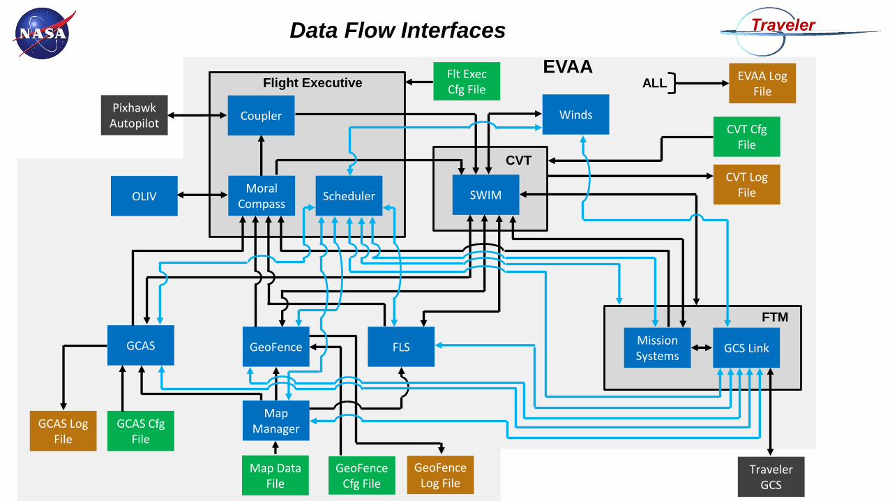
Data Flow Interfaces
Winds
Map Manager
OLIV
CVT Cfg File
Coupler
Moral Compass
Pixhawk Autopilot
TravelerGCS
Mission Systems
FLSGeoFenceGCAS
Flight Executive
FTM
SWIM
CVT
Map Data File
GCAS Cfg File
GeoFence Cfg File
Flt Exec Cfg File
CVT Log File
EVAA Log File
GCAS Log File
GeoFence Log File
ALL
Scheduler
GCS Link
EVAA
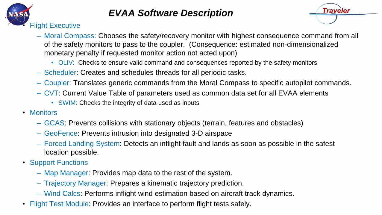
EVAA Software Description
• Flight Executive
– Moral Compass: Chooses the safety/recovery monitor with highest consequence command from all
of the safety monitors to pass to the coupler. (Consequence: estimated non-dimensionalized
monetary penalty if requested monitor action not acted upon)
• OLIV: Checks to ensure valid command and consequences reported by the safety monitors
– Scheduler: Creates and schedules threads for all periodic tasks.
– Coupler: Translates generic commands from the Moral Compass to specific autopilot commands.
– CVT: Current Value Table of parameters used as common data set for all EVAA elements
• SWIM: Checks the integrity of data used as inputs
• Monitors
– GCAS: Prevents collisions with stationary objects (terrain, features and obstacles)
– GeoFence: Prevents intrusion into designated 3-D airspace
– Forced Landing System: Detects an inflight fault and lands as soon as possible in the safest
location possible.
• Support Functions
– Map Manager: Provides map data to the rest of the system.
– Trajectory Manager: Prepares a kinematic trajectory prediction.
– Wind Calcs: Performs inflight wind estimation based on aircraft track dynamics.
• Flight Test Module: Provides an interface to perform flight tests safely.
Findings From EVAA Phase 1A
Requirements Development
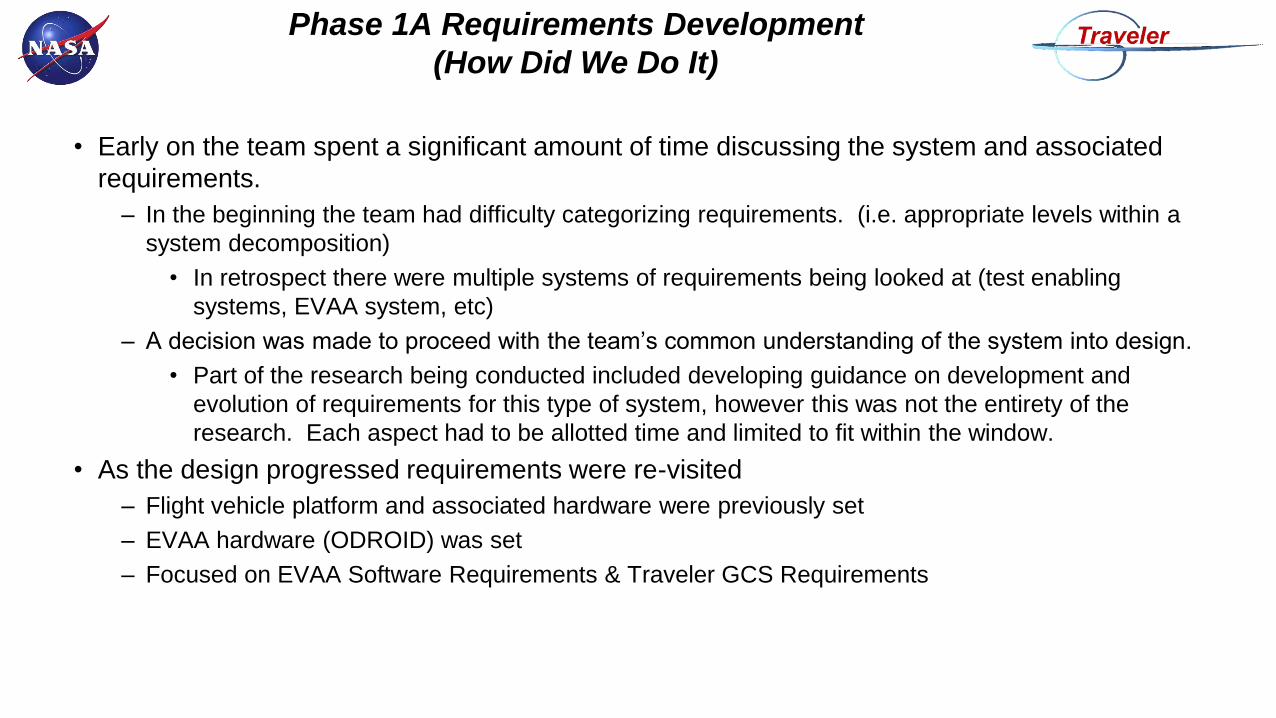
Phase 1A Requirements Development
(How Did We Do It)
• Early on the team spent a significant amount of time discussing the system and associated
requirements.
– In the beginning the team had difficulty categorizing requirements. (i.e. appropriate levels within a
system decomposition)
• In retrospect there were multiple systems of requirements being looked at (test enabling
systems, EVAA system, etc)
– A decision was made to proceed with the team’s common understanding of the system into design.
• Part of the research being conducted included developing guidance on development and
evolution of requirements for this type of system, however this was not the entirety of the
research. Each aspect had to be allotted time and limited to fit within the window.
• As the design progressed requirements were re-visited
– Flight vehicle platform and associated hardware were previously set
– EVAA hardware (ODROID) was set
– Focused on EVAA Software Requirements & Traveler GCS Requirements
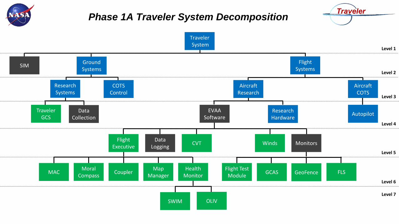
Phase 1A Traveler System Decomposition
TravelerSystem
Traveler GCS
Data Collection
Research Hardware
Autopilot
FlightSystems
AircraftResearch
AircraftCOTS
Research Systems
COTS Control
Ground Systems
SIM
CVTData
Logging
Flight Test Module
Winds
EVAA Software
MACMoral
CompassCoupler
Map Manager
Flight Executive
GCAS GeoFence FLS
Monitors
SWIM OLIV
Health Monitor
Level 1
Level 2
Level 3
Level 4
Level 5
Level 6
Level 7

How Could We Do It Better
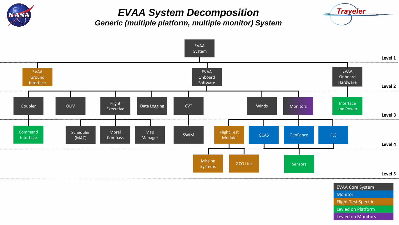
EVAA System DecompositionGeneric (multiple platform, multiple monitor) System
EVAA Ground
Interface
CVTData Logging
Flight Test Module
Winds
EVAA Onboard Software
Scheduler (MAC)
Moral Compass
Coupler
Map Manager
Flight Executive
GCAS GeoFence FLS
Monitors
SWIM
OLIV
Level 1
Level 2
Level 3
Level 4
Level 5
Sensors
Command Interface
EVAASystem
EVAA Onboard Hardware
Interface and Power
Mission Systems
GCO Link
EVAA Core System
Monitor
Flight Test Specific
Levied on Platform
Levied on Monitors
Data Flow Interfaces
Winds
Map Manager
OLIV
CVT Cfg File
Coupler
Moral Compass
Pixhawk Autopilot
TravelerGCS
Mission Systems
FLSGeoFenceGCAS
Flight Executive
FTM
SWIM
CVT
Map Data File
GCAS Cfg File
GeoFence Cfg File
Flt Exec Cfg File
CVT Log File
EVAA Log File
GCAS Log File
GeoFence Log File
ALL
Scheduler
GCS Link
EVAA
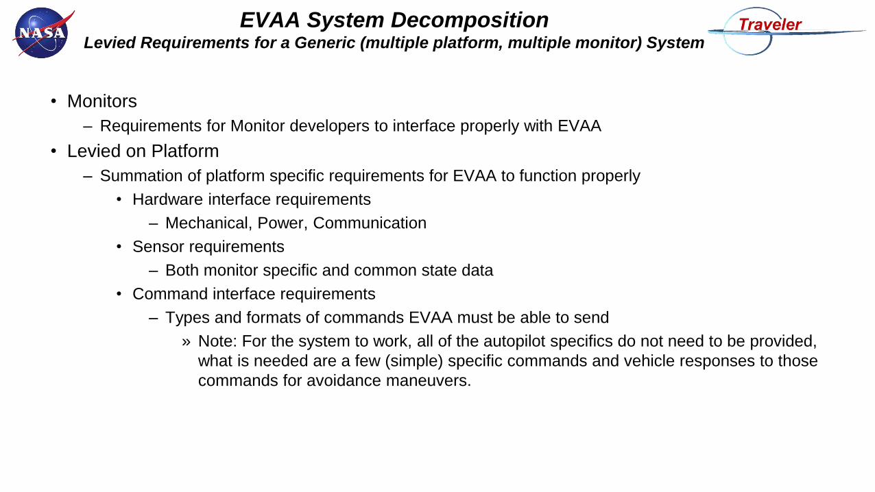
EVAA System DecompositionLevied Requirements for a Generic (multiple platform, multiple monitor) System
• Monitors
– Requirements for Monitor developers to interface properly with EVAA
• Levied on Platform
– Summation of platform specific requirements for EVAA to function properly
• Hardware interface requirements
– Mechanical, Power, Communication
• Sensor requirements
– Both monitor specific and common state data
• Command interface requirements
– Types and formats of commands EVAA must be able to send
» Note: For the system to work, all of the autopilot specifics do not need to be provided,
what is needed are a few (simple) specific commands and vehicle responses to those
commands for avoidance maneuvers.
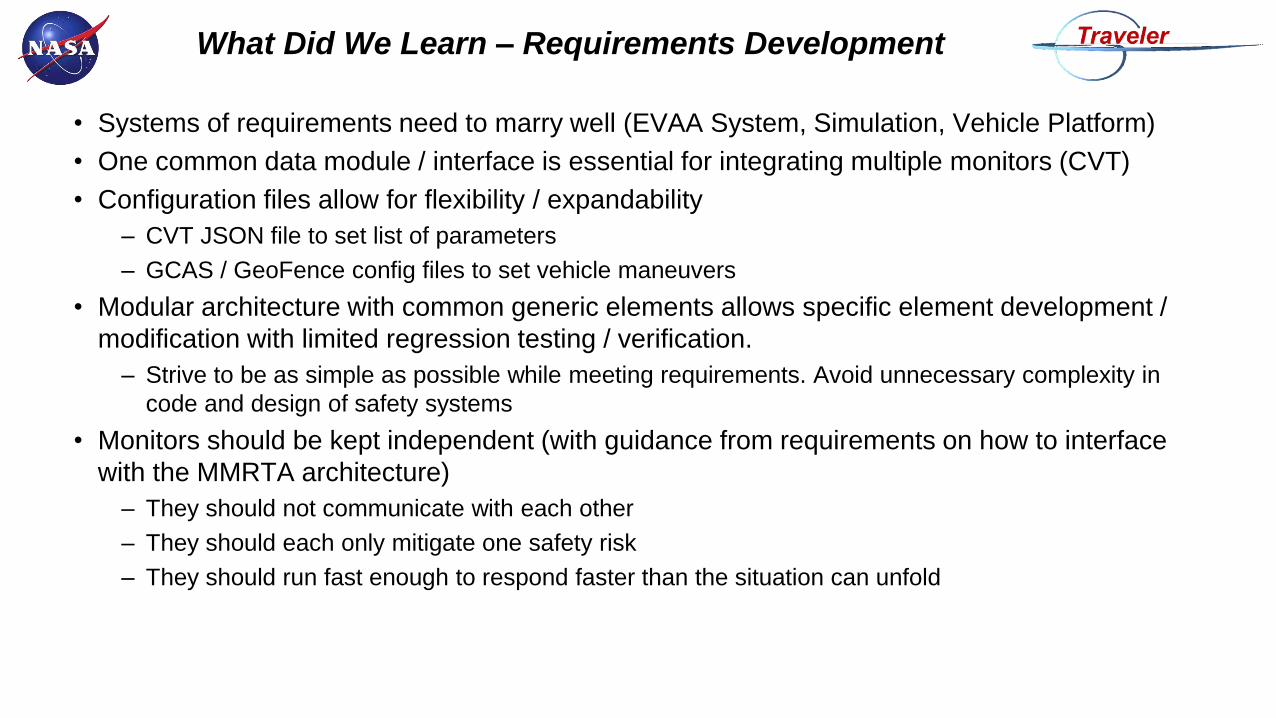
What Did We Learn – Requirements Development
• Systems of requirements need to marry well (EVAA System, Simulation, Vehicle Platform)
• One common data module / interface is essential for integrating multiple monitors (CVT)
• Configuration files allow for flexibility / expandability
– CVT JSON file to set list of parameters
– GCAS / GeoFence config files to set vehicle maneuvers
• Modular architecture with common generic elements allows specific element development /
modification with limited regression testing / verification.
– Strive to be as simple as possible while meeting requirements. Avoid unnecessary complexity in
code and design of safety systems
• Monitors should be kept independent (with guidance from requirements on how to interface
with the MMRTA architecture)
– They should not communicate with each other
– They should each only mitigate one safety risk
– They should run fast enough to respond faster than the situation can unfold
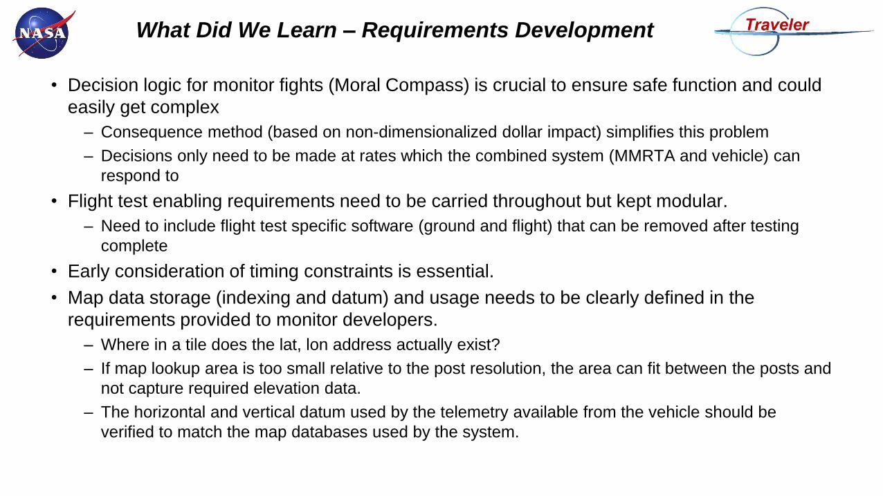
What Did We Learn – Requirements Development
• Decision logic for monitor fights (Moral Compass) is crucial to ensure safe function and could
easily get complex
– Consequence method (based on non-dimensionalized dollar impact) simplifies this problem
– Decisions only need to be made at rates which the combined system (MMRTA and vehicle) can
respond to
• Flight test enabling requirements need to be carried throughout but kept modular.
– Need to include flight test specific software (ground and flight) that can be removed after testing
complete
• Early consideration of timing constraints is essential.
• Map data storage (indexing and datum) and usage needs to be clearly defined in the
requirements provided to monitor developers.
– Where in a tile does the lat, lon address actually exist?
– If map lookup area is too small relative to the post resolution, the area can fit between the posts and
not capture required elevation data.
– The horizontal and vertical datum used by the telemetry available from the vehicle should be
verified to match the map databases used by the system.
Findings From EVAA Phase 1A
Design Development
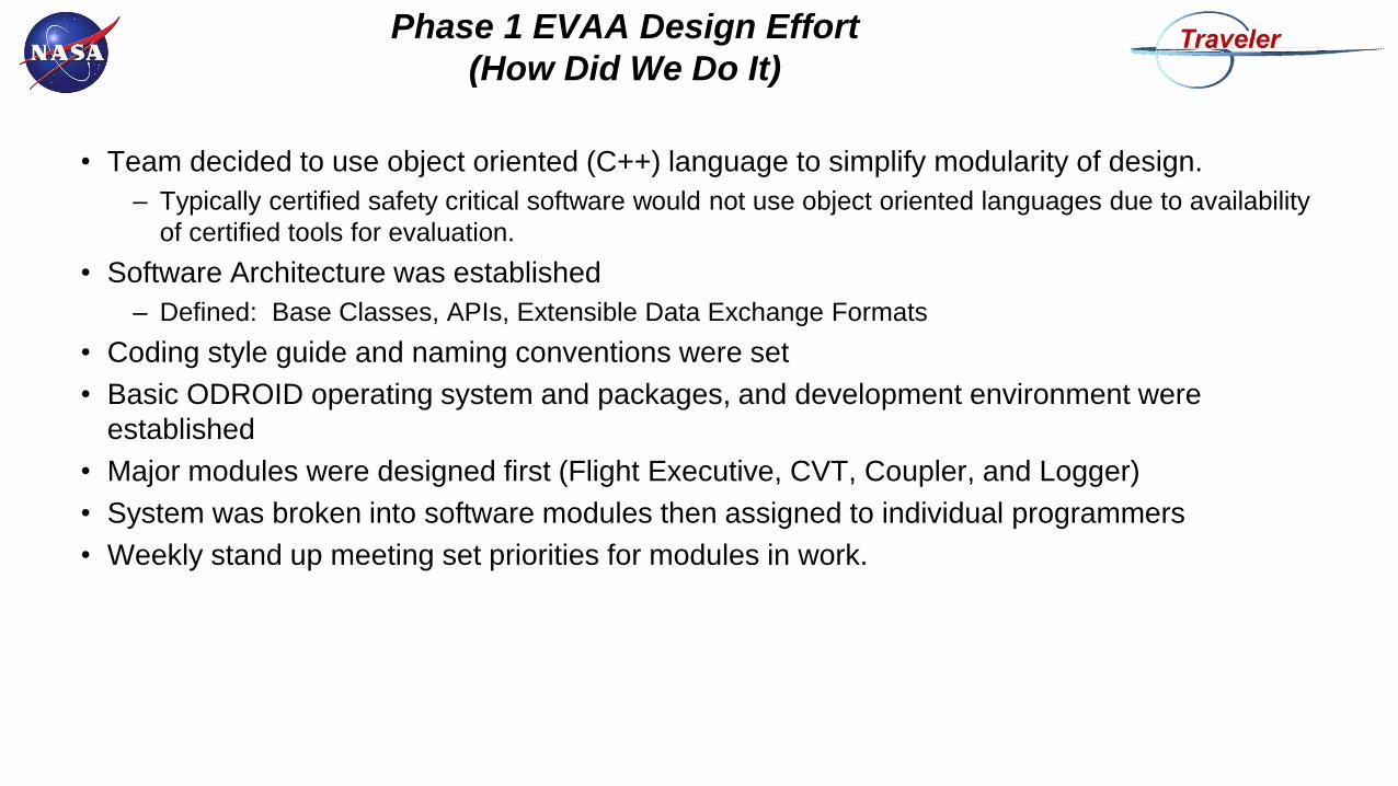
Phase 1 EVAA Design Effort
(How Did We Do It)
• Team decided to use object oriented (C++) language to simplify modularity of design.
– Typically certified safety critical software would not use object oriented languages due to availability
of certified tools for evaluation.
• Software Architecture was established
– Defined: Base Classes, APIs, Extensible Data Exchange Formats
• Coding style guide and naming conventions were set
• Basic ODROID operating system and packages, and development environment were
established
• Major modules were designed first (Flight Executive, CVT, Coupler, and Logger)
• System was broken into software modules then assigned to individual programmers
• Weekly stand up meeting set priorities for modules in work.
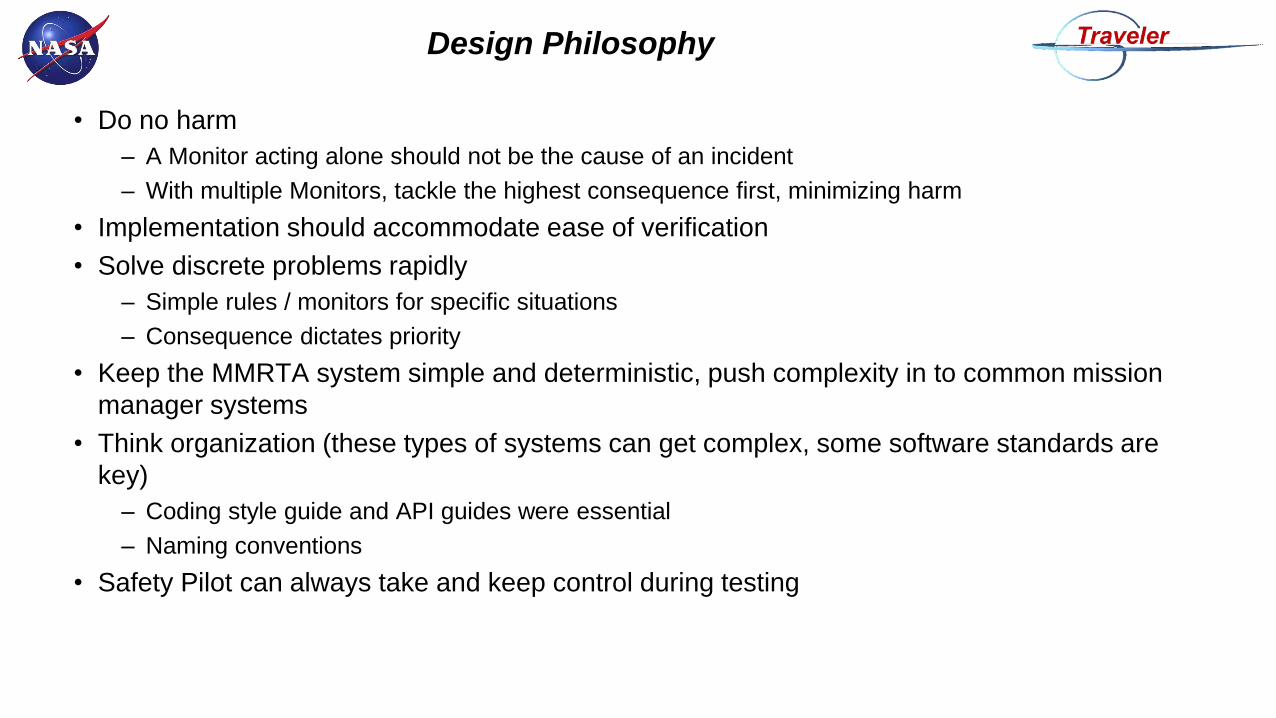
Design Philosophy
• Do no harm
– A Monitor acting alone should not be the cause of an incident
– With multiple Monitors, tackle the highest consequence first, minimizing harm
• Implementation should accommodate ease of verification
• Solve discrete problems rapidly
– Simple rules / monitors for specific situations
– Consequence dictates priority
• Keep the MMRTA system simple and deterministic, push complexity in to common mission
manager systems
• Think organization (these types of systems can get complex, some software standards are
key)
– Coding style guide and API guides were essential
– Naming conventions
• Safety Pilot can always take and keep control during testing
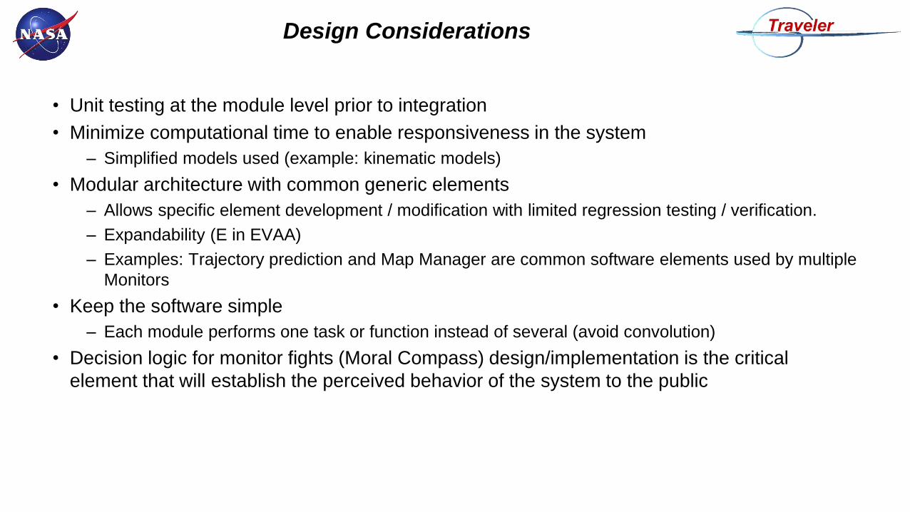
Design Considerations
• Unit testing at the module level prior to integration
• Minimize computational time to enable responsiveness in the system
– Simplified models used (example: kinematic models)
• Modular architecture with common generic elements
– Allows specific element development / modification with limited regression testing / verification.
– Expandability (E in EVAA)
– Examples: Trajectory prediction and Map Manager are common software elements used by multiple
Monitors
• Keep the software simple
– Each module performs one task or function instead of several (avoid convolution)
• Decision logic for monitor fights (Moral Compass) design/implementation is the critical
element that will establish the perceived behavior of the system to the public
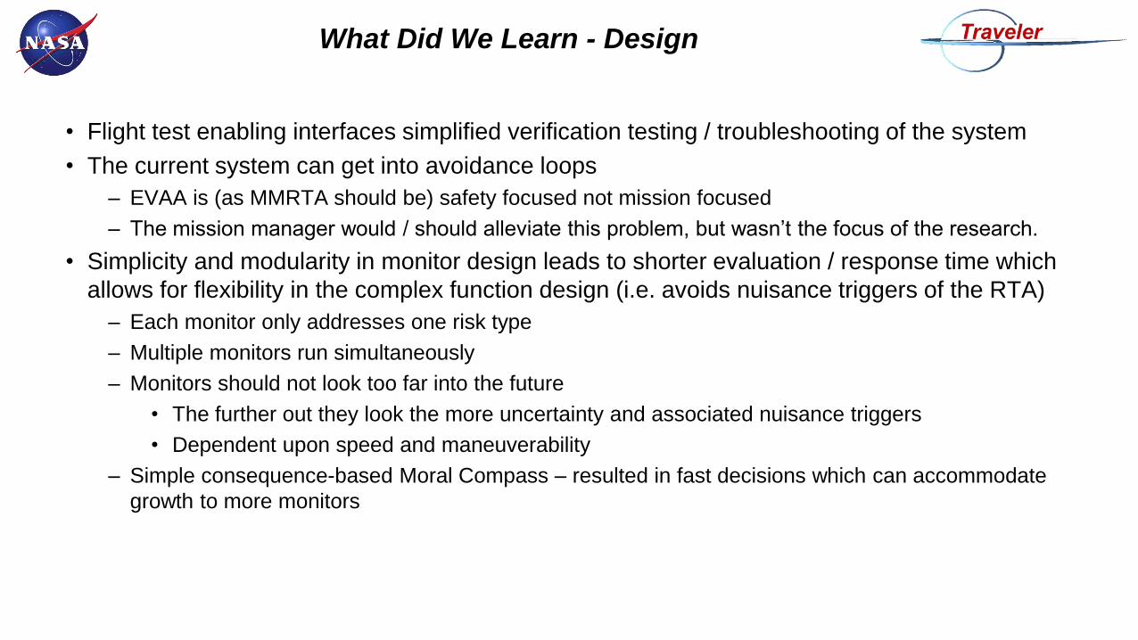
What Did We Learn - Design
• Flight test enabling interfaces simplified verification testing / troubleshooting of the system
• The current system can get into avoidance loops
– EVAA is (as MMRTA should be) safety focused not mission focused
– The mission manager would / should alleviate this problem, but wasn’t the focus of the research.
• Simplicity and modularity in monitor design leads to shorter evaluation / response time which
allows for flexibility in the complex function design (i.e. avoids nuisance triggers of the RTA)
– Each monitor only addresses one risk type
– Multiple monitors run simultaneously
– Monitors should not look too far into the future
• The further out they look the more uncertainty and associated nuisance triggers
• Dependent upon speed and maneuverability
– Simple consequence-based Moral Compass – resulted in fast decisions which can accommodate
growth to more monitors
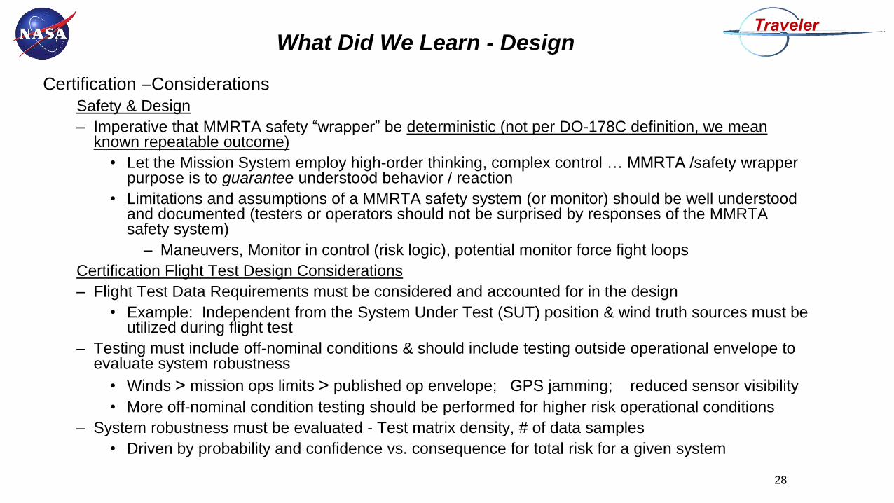
What Did We Learn - Design
Certification –Considerations
Safety & Design
– Imperative that MMRTA safety “wrapper” be deterministic (not per DO-178C definition, we mean known repeatable outcome)
• Let the Mission System employ high-order thinking, complex control … MMRTA /safety wrapper purpose is to guarantee understood behavior / reaction
• Limitations and assumptions of a MMRTA safety system (or monitor) should be well understood and documented (testers or operators should not be surprised by responses of the MMRTA safety system)
– Maneuvers, Monitor in control (risk logic), potential monitor force fight loops
Certification Flight Test Design Considerations
– Flight Test Data Requirements must be considered and accounted for in the design
• Example: Independent from the System Under Test (SUT) position & wind truth sources must be utilized during flight test
– Testing must include off-nominal conditions & should include testing outside operational envelope to evaluate system robustness
• Winds > mission ops limits > published op envelope; GPS jamming; reduced sensor visibility
• More off-nominal condition testing should be performed for higher risk operational conditions
– System robustness must be evaluated - Test matrix density, # of data samples
• Driven by probability and confidence vs. consequence for total risk for a given system
28
What Did We Learn - Design
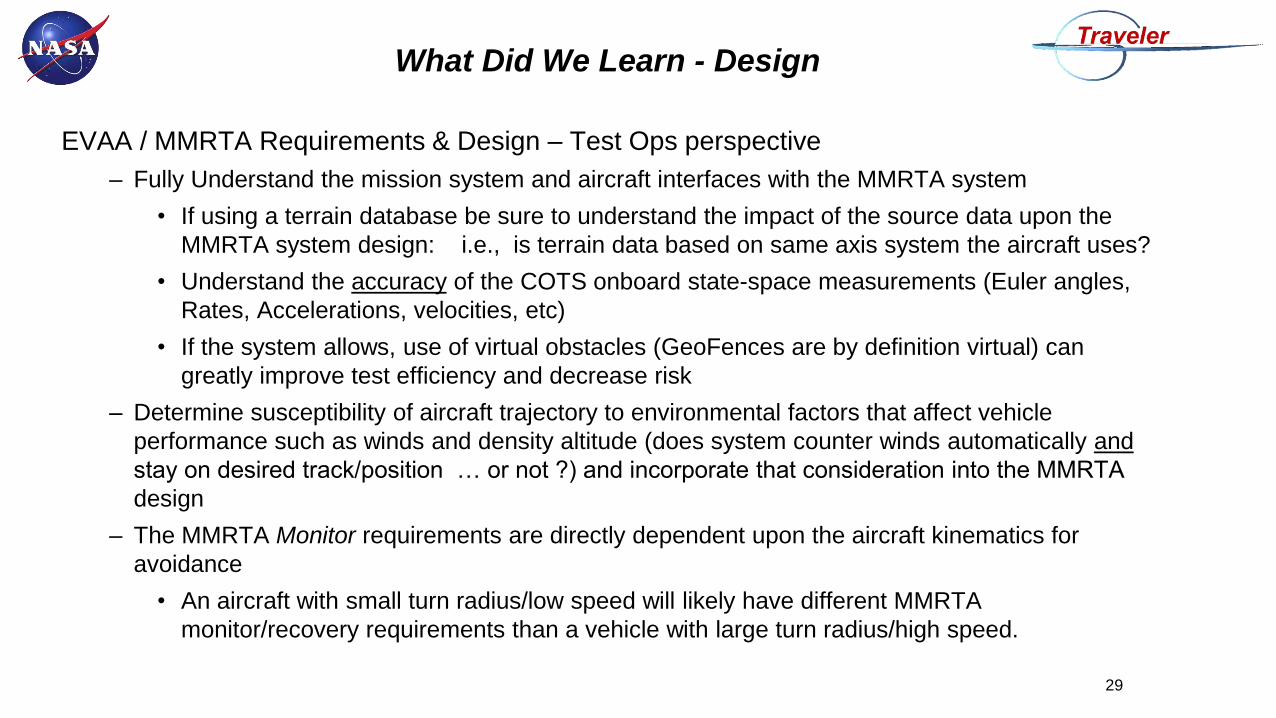
EVAA / MMRTA Requirements & Design – Test Ops perspective
– Fully Understand the mission system and aircraft interfaces with the MMRTA system
• If using a terrain database be sure to understand the impact of the source data upon the
MMRTA system design: i.e., is terrain data based on same axis system the aircraft uses?
• Understand the accuracy of the COTS onboard state-space measurements (Euler angles,
Rates, Accelerations, velocities, etc)
• If the system allows, use of virtual obstacles (GeoFences are by definition virtual) can
greatly improve test efficiency and decrease risk
– Determine susceptibility of aircraft trajectory to environmental factors that affect vehicle
performance such as winds and density altitude (does system counter winds automatically and
stay on desired track/position … or not ?) and incorporate that consideration into the MMRTA
design
– The MMRTA Monitor requirements are directly dependent upon the aircraft kinematics for
avoidance
• An aircraft with small turn radius/low speed will likely have different MMRTA
monitor/recovery requirements than a vehicle with large turn radius/high speed.
29
Findings From EVAA Phase 1A
Test Approach
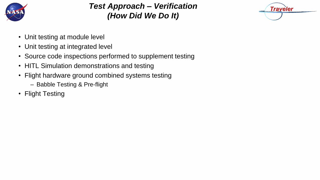
Test Approach – Verification
(How Did We Do It)
• Unit testing at module level
• Unit testing at integrated level
• Source code inspections performed to supplement testing
• HITL Simulation demonstrations and testing
• Flight hardware ground combined systems testing
– Babble Testing & Pre-flight
• Flight Testing
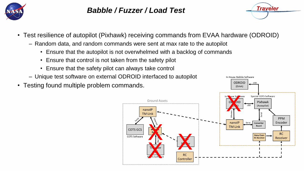
Babble / Fuzzer / Load Test
• Test resilience of autopilot (Pixhawk) receiving commands from EVAA hardware (ODROID)
– Random data, and random commands were sent at max rate to the autopilot
• Ensure that the autopilot is not overwhelmed with a backlog of commands
• Ensure that control is not taken from the safety pilot
• Ensure that the safety pilot can always take control
– Unique test software on external ODROID interfaced to autopilot
• Testing found multiple problem commands.
Test Approach – Verification
(What Did We Learn)
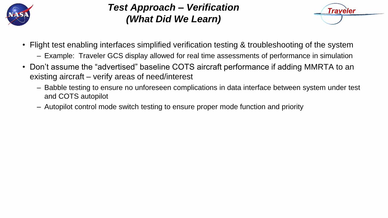
• Flight test enabling interfaces simplified verification testing & troubleshooting of the system
– Example: Traveler GCS display allowed for real time assessments of performance in simulation
• Don’t assume the “advertised” baseline COTS aircraft performance if adding MMRTA to an
existing aircraft – verify areas of need/interest
– Babble testing to ensure no unforeseen complications in data interface between system under test
and COTS autopilot
– Autopilot control mode switch testing to ensure proper mode function and priority

Test Approach – Flight Test
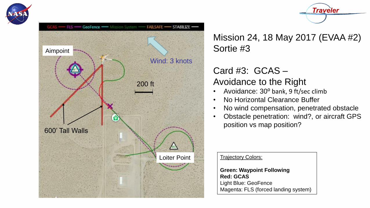
Mission 24, 18 May 2017 (EVAA #2)
Sortie #3
Card #3: GCAS –
Avoidance to the Right• Avoidance: 30⁰ bank, 9 ft/sec climb• No Horizontal Clearance Buffer
• No wind compensation, penetrated obstacle
• Obstacle penetration: wind?, or aircraft GPS
position vs map position?600’ Tall Walls
Aimpoint
Loiter Point
Wind: 3 knots
200 ft
Trajectory Colors:
Green: Waypoint Following
Red: GCAS
Light Blue: GeoFence
Magenta: FLS (forced landing system)
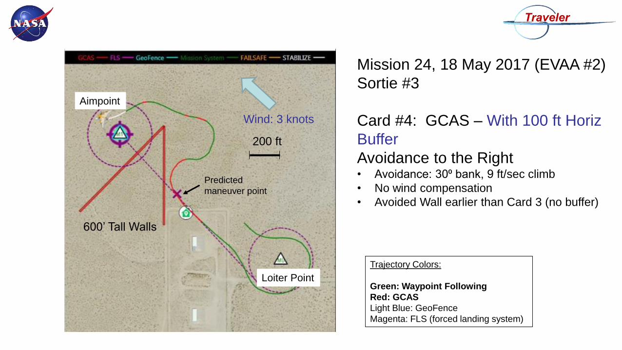
Mission 24, 18 May 2017 (EVAA #2)
Sortie #3
Card #4: GCAS – With 100 ft Horiz
Buffer
Avoidance to the Right• Avoidance: 30⁰ bank, 9 ft/sec climb
• No wind compensation
• Avoided Wall earlier than Card 3 (no buffer)
600’ Tall Walls
Aimpoint
Loiter Point
Wind: 3 knots
200 ft
Trajectory Colors:
Green: Waypoint Following
Red: GCAS
Light Blue: GeoFence
Magenta: FLS (forced landing system)
Predicted
maneuver point
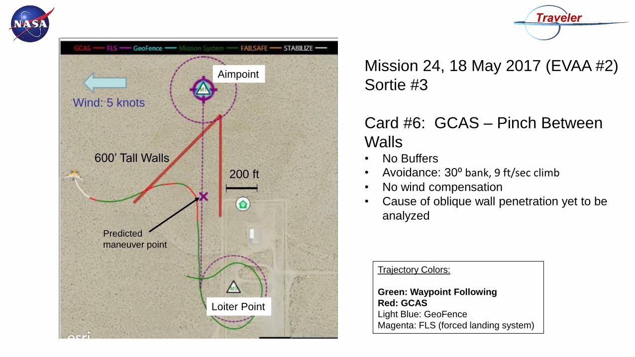
Mission 24, 18 May 2017 (EVAA #2)
Sortie #3
Card #6: GCAS – Pinch Between
Walls• No Buffers
• Avoidance: 30⁰ bank, 9 ft/sec climb• No wind compensation
• Cause of oblique wall penetration yet to be
analyzed
600’ Tall Walls
Aimpoint
Loiter Point
Wind: 5 knots
200 ft
Trajectory Colors:
Green: Waypoint Following
Red: GCAS
Light Blue: GeoFence
Magenta: FLS (forced landing system)
Predicted
maneuver point
Mission 24, 18 May 2017 (EVAA #2)
Sortie #3
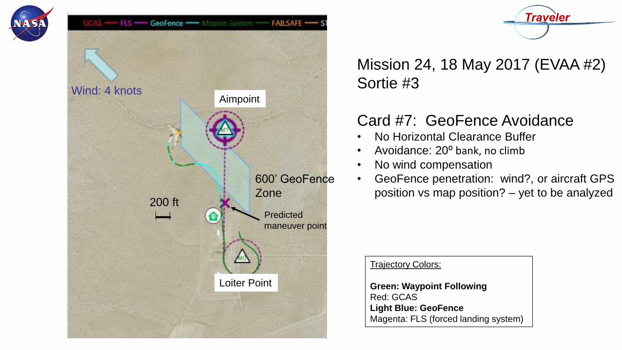
Card #7: GeoFence Avoidance• No Horizontal Clearance Buffer
• Avoidance: 20⁰ bank, no climb• No wind compensation
• GeoFence penetration: wind?, or aircraft GPS
position vs map position? – yet to be analyzed
600’ GeoFence
Zone
Aimpoint
Loiter Point
Wind: 4 knots
200 ft
Trajectory Colors:
Green: Waypoint Following
Red: GCAS
Light Blue: GeoFence
Magenta: FLS (forced landing system)
Predicted
maneuver point
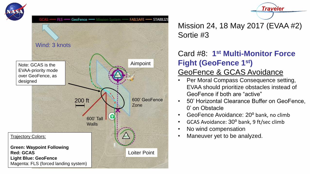
Mission 24, 18 May 2017 (EVAA #2)
Sortie #3
Card #8: 1st Multi-Monitor Force
Fight (GeoFence 1st)
GeoFence & GCAS Avoidance• Per Moral Compass Consequence setting,
EVAA should prioritize obstacles instead of
GeoFence if both are “active”
• 50’ Horizontal Clearance Buffer on GeoFence,
0’ on Obstacle
• GeoFence Avoidance: 20⁰ bank, no climb• GCAS Avoidance: 30⁰ bank, 9 ft/sec climb• No wind compensation
• Maneuver yet to be analyzed.
600’ GeoFence
Zone
Aimpoint
Loiter Point
Wind: 3 knots
200 ft
Trajectory Colors:
Green: Waypoint Following
Red: GCAS
Light Blue: GeoFence
Magenta: FLS (forced landing system)
600’ Tall
Walls
Note: GCAS is the
EVAA-priority mode
over GeoFence, as
designed
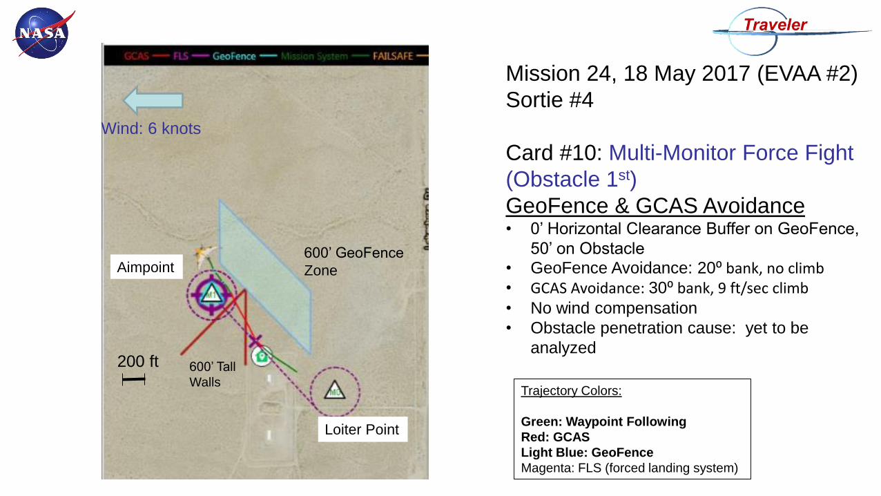
Mission 24, 18 May 2017 (EVAA #2)
Sortie #4
Card #10: Multi-Monitor Force Fight
(Obstacle 1st)
GeoFence & GCAS Avoidance• 0’ Horizontal Clearance Buffer on GeoFence,
50’ on Obstacle
• GeoFence Avoidance: 20⁰ bank, no climb• GCAS Avoidance: 30⁰ bank, 9 ft/sec climb• No wind compensation
• Obstacle penetration cause: yet to be
analyzed
600’ GeoFence
ZoneAimpoint
Loiter Point
Wind: 6 knots
200 ft
Trajectory Colors:
Green: Waypoint Following
Red: GCAS
Light Blue: GeoFence
Magenta: FLS (forced landing system)
600’ Tall
Walls
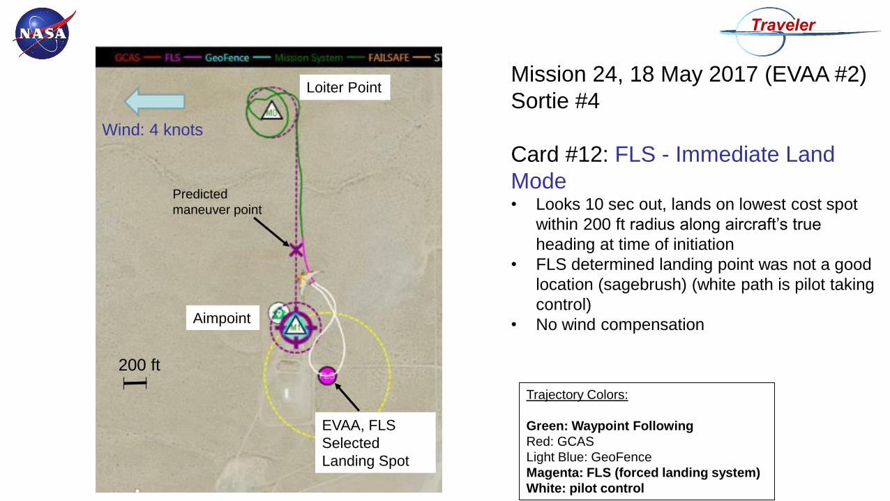
Mission 24, 18 May 2017 (EVAA #2)
Sortie #4
Card #12: FLS - Immediate Land
Mode• Looks 10 sec out, lands on lowest cost spot
within 200 ft radius along aircraft’s true
heading at time of initiation
• FLS determined landing point was not a good
location (sagebrush) (white path is pilot taking
control)
• No wind compensationAimpoint
Loiter Point
Wind: 4 knots
200 ft
Trajectory Colors:
Green: Waypoint Following
Red: GCAS
Light Blue: GeoFence
Magenta: FLS (forced landing system)
White: pilot control
EVAA, FLS
Selected
Landing Spot
Predicted
maneuver point
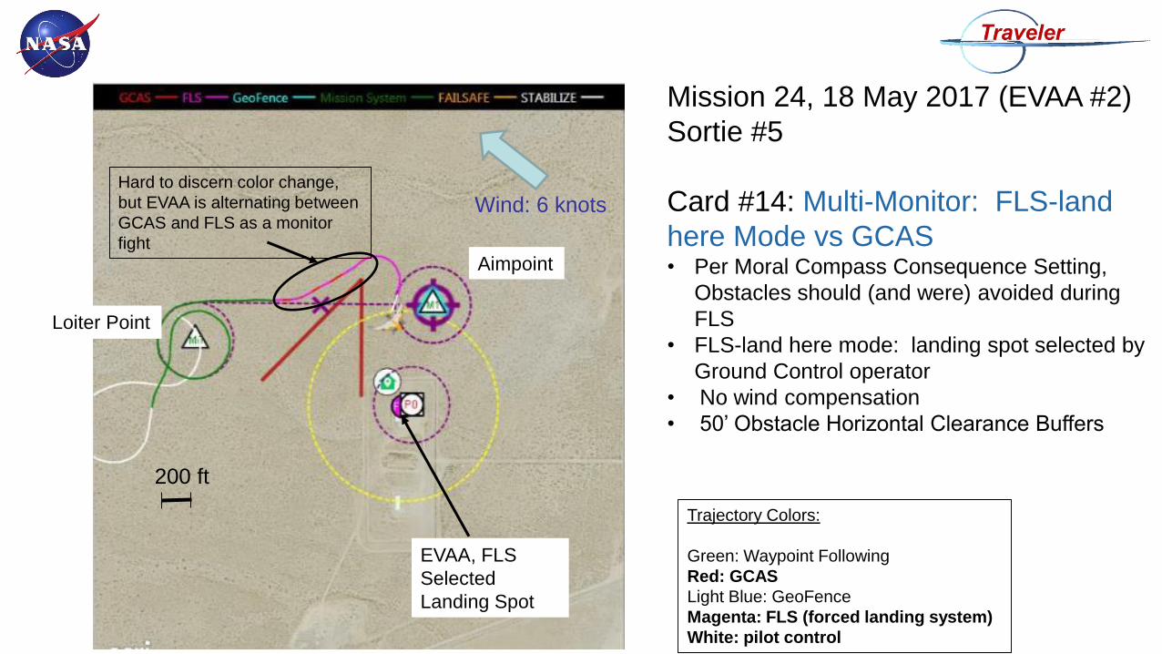
Mission 24, 18 May 2017 (EVAA #2)
Sortie #5
Card #14: Multi-Monitor: FLS-land
here Mode vs GCAS • Per Moral Compass Consequence Setting,
Obstacles should (and were) avoided during
FLS
• FLS-land here mode: landing spot selected by
Ground Control operator
• No wind compensation
• 50’ Obstacle Horizontal Clearance Buffers
Aimpoint
Loiter Point
Wind: 6 knots
200 ft
Trajectory Colors:
Green: Waypoint Following
Red: GCAS
Light Blue: GeoFence
Magenta: FLS (forced landing system)
White: pilot control
EVAA, FLS
Selected
Landing Spot
Hard to discern color change,
but EVAA is alternating between
GCAS and FLS as a monitor
fight
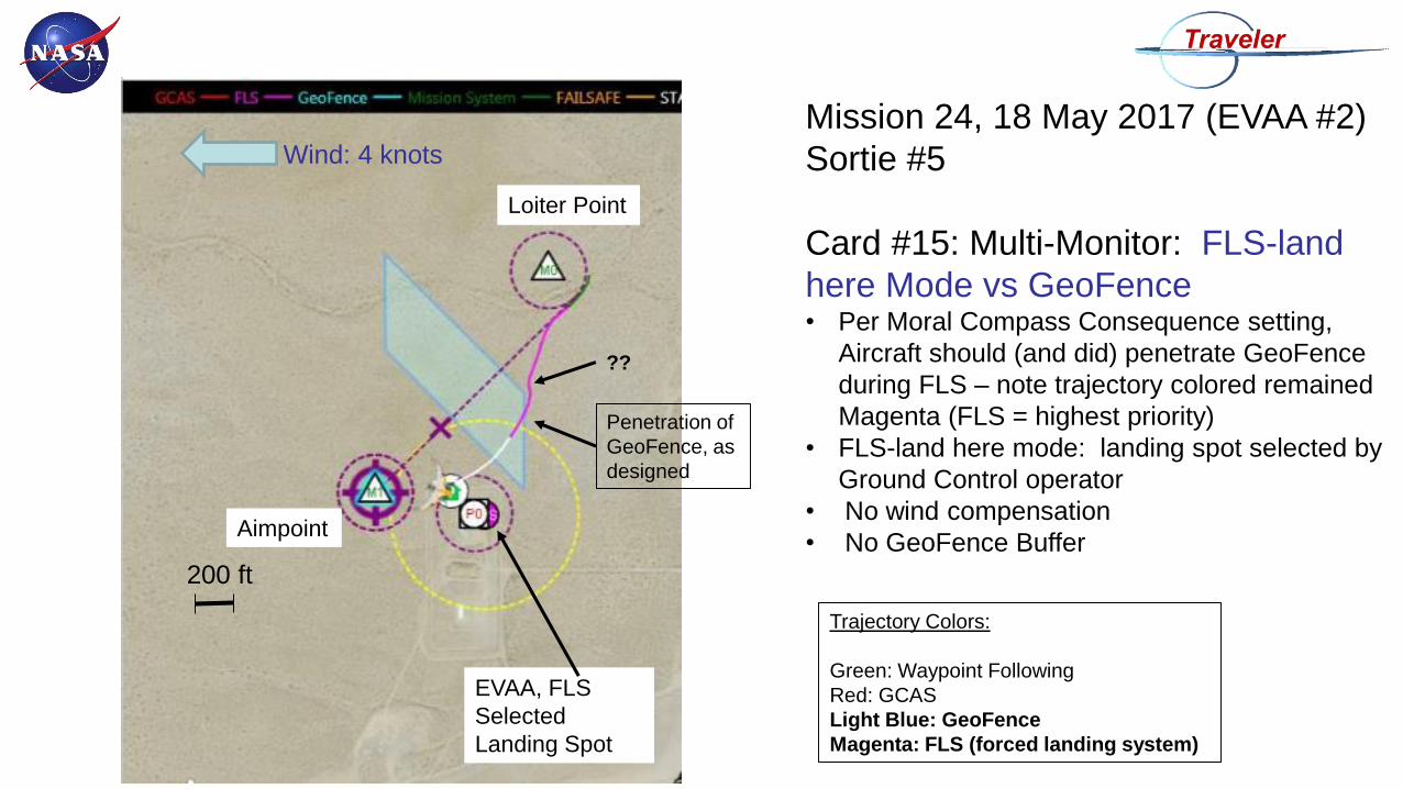
Mission 24, 18 May 2017 (EVAA #2)
Sortie #5
Card #15: Multi-Monitor: FLS-land
here Mode vs GeoFence• Per Moral Compass Consequence setting,
Aircraft should (and did) penetrate GeoFence
during FLS – note trajectory colored remained
Magenta (FLS = highest priority)
• FLS-land here mode: landing spot selected by
Ground Control operator
• No wind compensation
• No GeoFence BufferAimpoint
Loiter Point
Wind: 4 knots
200 ft
Trajectory Colors:
Green: Waypoint Following
Red: GCAS
Light Blue: GeoFence
Magenta: FLS (forced landing system)
EVAA, FLS
Selected
Landing Spot
Penetration of
GeoFence, as
designed
??
Mission 24, 18 May 2017 (EVAA #2)
Sortie #5
Card #16: Triple Multi-Monitor: FLS-
land here Mode vs GeoFence vs
GCAS• Unfortunately, did not initiate a screen capture
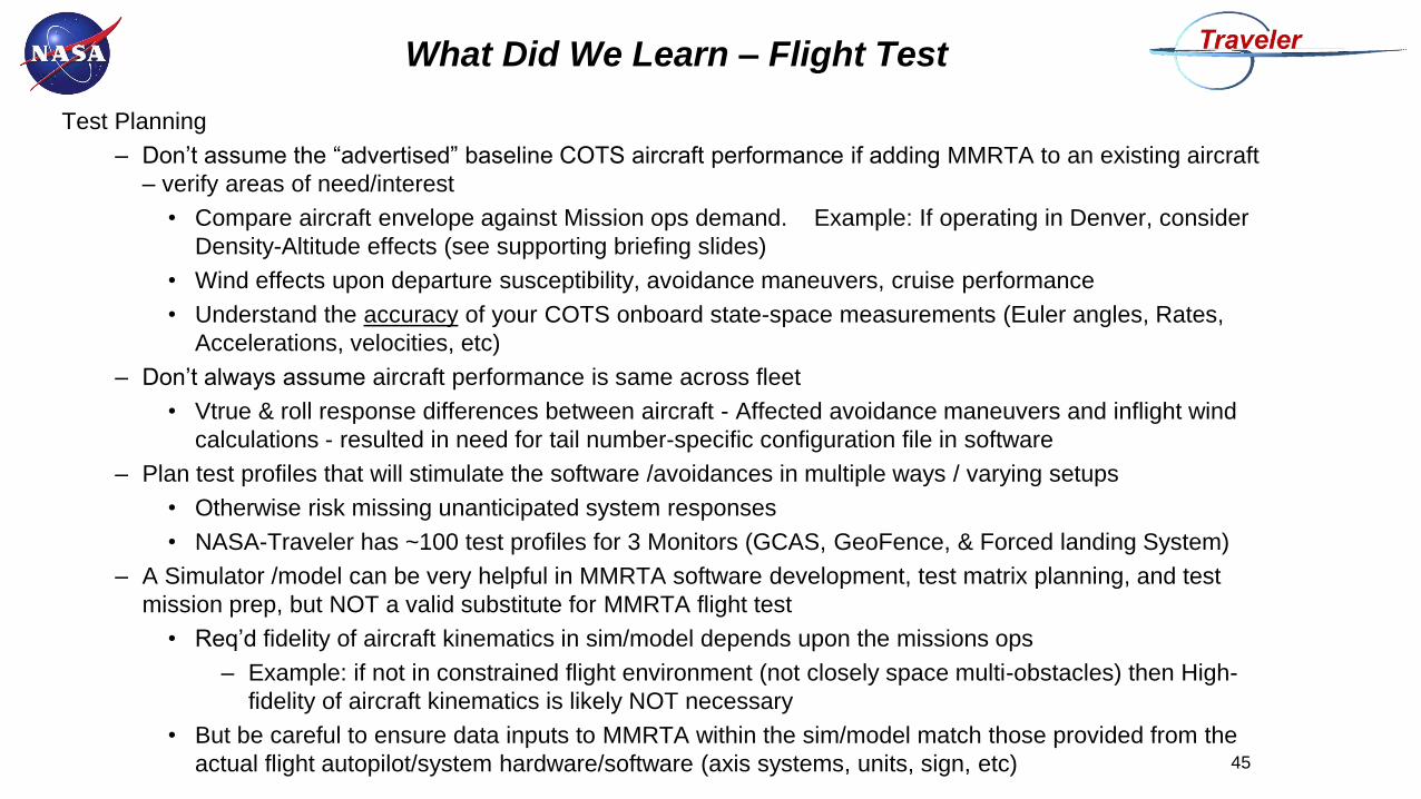
Test Planning
– Don’t assume the “advertised” baseline COTS aircraft performance if adding MMRTA to an existing aircraft
– verify areas of need/interest
• Compare aircraft envelope against Mission ops demand. Example: If operating in Denver, consider
Density-Altitude effects (see supporting briefing slides)
• Wind effects upon departure susceptibility, avoidance maneuvers, cruise performance
• Understand the accuracy of your COTS onboard state-space measurements (Euler angles, Rates,
Accelerations, velocities, etc)
– Don’t always assume aircraft performance is same across fleet
• Vtrue & roll response differences between aircraft - Affected avoidance maneuvers and inflight wind
calculations - resulted in need for tail number-specific configuration file in software
– Plan test profiles that will stimulate the software /avoidances in multiple ways / varying setups
• Otherwise risk missing unanticipated system responses
• NASA-Traveler has ~100 test profiles for 3 Monitors (GCAS, GeoFence, & Forced landing System)
– A Simulator /model can be very helpful in MMRTA software development, test matrix planning, and test
mission prep, but NOT a valid substitute for MMRTA flight test
• Req’d fidelity of aircraft kinematics in sim/model depends upon the missions ops
– Example: if not in constrained flight environment (not closely space multi-obstacles) then High-
fidelity of aircraft kinematics is likely NOT necessary
• But be careful to ensure data inputs to MMRTA within the sim/model match those provided from the
actual flight autopilot/system hardware/software (axis systems, units, sign, etc) 45
What Did We Learn – Flight Test
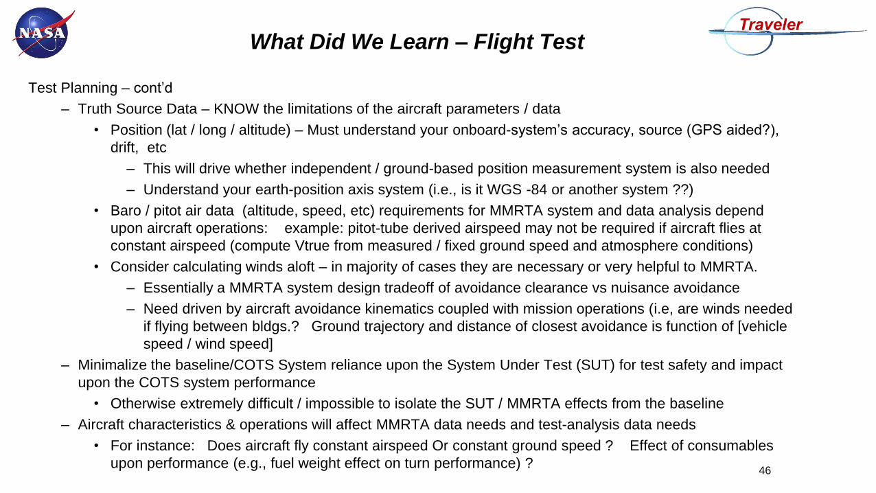
Test Planning – cont’d
– Truth Source Data – KNOW the limitations of the aircraft parameters / data
• Position (lat / long / altitude) – Must understand your onboard-system’s accuracy, source (GPS aided?),
drift, etc
– This will drive whether independent / ground-based position measurement system is also needed
– Understand your earth-position axis system (i.e., is it WGS -84 or another system ??)
• Baro / pitot air data (altitude, speed, etc) requirements for MMRTA system and data analysis depend
upon aircraft operations: example: pitot-tube derived airspeed may not be required if aircraft flies at
constant airspeed (compute Vtrue from measured / fixed ground speed and atmosphere conditions)
• Consider calculating winds aloft – in majority of cases they are necessary or very helpful to MMRTA.
– Essentially a MMRTA system design tradeoff of avoidance clearance vs nuisance avoidance
– Need driven by aircraft avoidance kinematics coupled with mission operations (i.e, are winds needed
if flying between bldgs.? Ground trajectory and distance of closest avoidance is function of [vehicle
speed / wind speed]
– Minimalize the baseline/COTS System reliance upon the System Under Test (SUT) for test safety and impact
upon the COTS system performance
• Otherwise extremely difficult / impossible to isolate the SUT / MMRTA effects from the baseline
– Aircraft characteristics & operations will affect MMRTA data needs and test-analysis data needs
• For instance: Does aircraft fly constant airspeed Or constant ground speed ? Effect of consumables
upon performance (e.g., fuel weight effect on turn performance) ?46
What Did We Learn – Flight Test
What Did We Learn – Flight Test
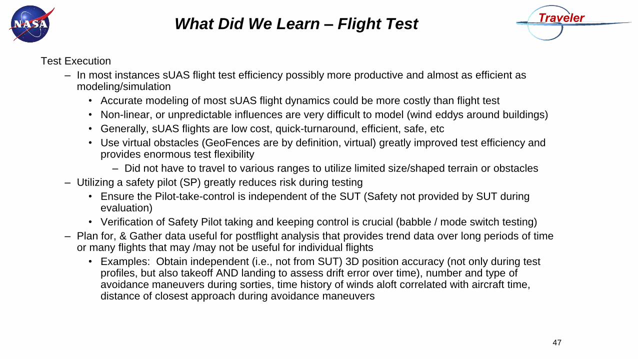
Test Execution
– In most instances sUAS flight test efficiency possibly more productive and almost as efficient as modeling/simulation
• Accurate modeling of most sUAS flight dynamics could be more costly than flight test
• Non-linear, or unpredictable influences are very difficult to model (wind eddys around buildings)
• Generally, sUAS flights are low cost, quick-turnaround, efficient, safe, etc
• Use virtual obstacles (GeoFences are by definition, virtual) greatly improved test efficiency and provides enormous test flexibility
– Did not have to travel to various ranges to utilize limited size/shaped terrain or obstacles
– Utilizing a safety pilot (SP) greatly reduces risk during testing
• Ensure the Pilot-take-control is independent of the SUT (Safety not provided by SUT during evaluation)
• Verification of Safety Pilot taking and keeping control is crucial (babble / mode switch testing)
– Plan for, & Gather data useful for postflight analysis that provides trend data over long periods of time or many flights that may /may not be useful for individual flights
• Examples: Obtain independent (i.e., not from SUT) 3D position accuracy (not only during test profiles, but also takeoff AND landing to assess drift error over time), number and type of avoidance maneuvers during sorties, time history of winds aloft correlated with aircraft time, distance of closest approach during avoidance maneuvers
47
What Did We Learn – Flight Test
• Flight test enabling interfaces simplified verification testing / troubleshooting of the system
– Implemented ability to turn monitors ON/OFF/Standby, thus providing improved test efficiency and
better control of test buildup
• Improved ability to use virtual obstacles & GeoFences that could be “de-activated” when not
needed in order to prevent interference
• Standby allows data capture without vehicle response

Standard Practice Review
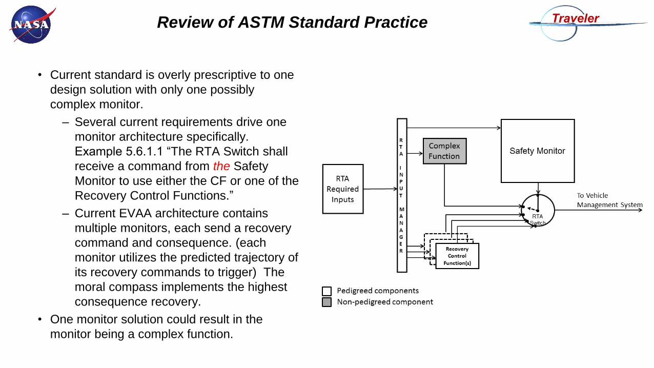
Review of ASTM Standard Practice
• Current standard is overly prescriptive to one
design solution with only one possibly
complex monitor.
– Several current requirements drive one
monitor architecture specifically.
Example 5.6.1.1 “The RTA Switch shall
receive a command from the Safety
Monitor to use either the CF or one of the
Recovery Control Functions.”
– Current EVAA architecture contains
multiple monitors, each send a recovery
command and consequence. (each
monitor utilizes the predicted trajectory of
its recovery commands to trigger) The
moral compass implements the highest
consequence recovery.
• One monitor solution could result in the
monitor being a complex function.
RTA Input
Manager
(CVT) Veh
icle
Man
ag
em
en
t S
yste
m
Safety Monitors
(With Recovery
Maneuvers)
SensorsSensors
SensorsSensors RTA
Switch
Complex
Function
(Untrusted
System) Baseline Aircraft
RTA Trusted Functions
Untrusted Controllers
Legend
Sensors
Current EVAA MMRTA Framework
51
Coupler
(Moral Compass)
*Note: Recovery maneuvers are contained within monitors, but may be updated via
configuration file for modularity / adaptability across platforms.
Review of ASTM Standard Practice
• General recommendations:
– Eliminate requirements that prescribe one design solution
– Include design guidance section to fill gap between general requirements and recommended
practices
– Include certification verification guidance section for the same reasons
• See lessons learned from testing / evaluation
– Include checks on recovery functions to ensure appropriate for the condition
– The document reads as though only UAS manufacturers would build these types of systems. Third
party entities are not accounted for in the guidance and should be. (Applicants may not be UAS
manufacturers)
– More detail should be provided on monitor performance vs complex function performance
• Avoid Nuisance RTA triggers …. i.e. Monitors should not look too far into the future / react so
far out they limit the complex function unnecessarily
Review of ASTM Standard Practice
• 1.2 – “enabling highly automated UAS operations” … to include autonomous?
• 1.3 – “Certification challenges under DO-178C include generating required artifacts, such as
requirements, elimination of unintended functionality, traceability/coverage, and test cases
required for verification.” … the issue isn’t in requirements definition, but instead adequate
test case definition.
• 1.5.5 – “An RTA design with multiple RCFs should consider the aircraft state, relative
outcomes, and differences in RTA recovery times in prioritizing the recovery actions in the
Safety Monitor.” … include aircraft kinematics (might be what was meant by relative
outcomes)
• 3.1 Definitions - “Safety Monitor – Continually monitors aircraft state including performance
and functioning of the complex function to determine if the aircraft is or is predicted to exceed
Pre-defined Limits. As necessary it will control the safety switch” … think you mean RTA
Switch
• 5.1.3.1.2 – “The UAS manufacturer shall consider the impact to risk from the an incorrect
action commanded by the Safety Monitor, RTA Switch, and/or the Recovery Control
Function(s).” … consider is unverifiable / open ended
• 5.1.5.1.1 – “Run-time assurance architecture” … assuming you mean architecture description
document
Review of ASTM Standard Practice
• 5.1.5.2.2 – “Simulation and/or flight test results from anticipated environmental conditions and
missions where the Recovery Control Function(s) are not expected to activate.” and 5.1.5.2.3
– “Simulation and/or flight test results of stressing cases that cause the activation of all
Recovery Control Function(s) relative to the Concept of Operations.”
– There are some significant limitations to simulation of sUAS, more is needed to substantiate
function.
• 5.1.5.4.2 - “Methods acceptable to the CAA may be used to identify the artifacts required for
complex airborne electronic hardware.” ... Confusing as CAA acceptable methods would by
default have to be complied with
• 5.2.3.1.1 – “The UAS manufacturer should take into account the vehicle dynamics,
environmental dynamics, and Safety Monitor thresholds in determining the frequency,
accuracy, and precision requirements of each data element.” … depending on the data
element this might need to be a shall (whether or not it feeds safety critical functions)
• 5.3.2.4 – “The RTA Input Manager should calculate and report estimated uncertainty of the
measured state of the UAS resulting from deviations in precision, accuracy, and latency of the
state variables.” … overly prescriptive, uncertainty must be accounted for, but there are other
ways to account for uncertainty than in the RTA Input Manager
Review of ASTM Standard Practice
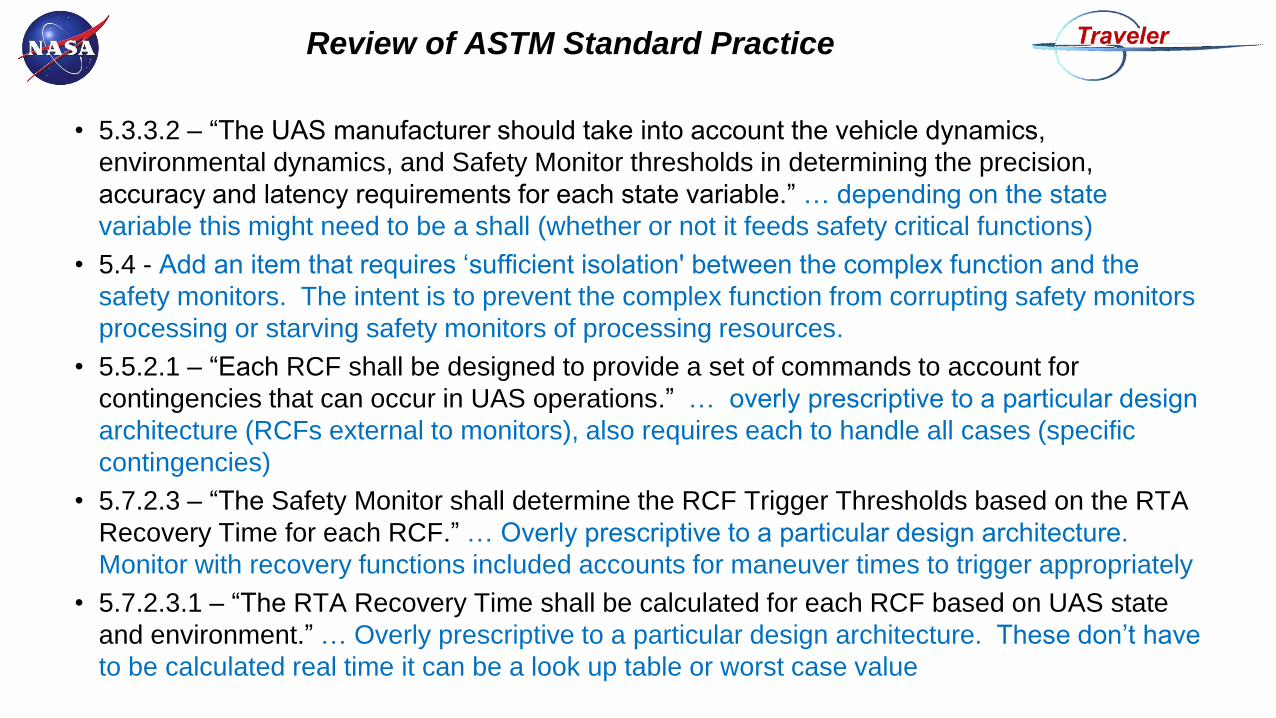
• 5.3.3.2 – “The UAS manufacturer should take into account the vehicle dynamics,
environmental dynamics, and Safety Monitor thresholds in determining the precision,
accuracy and latency requirements for each state variable.” … depending on the state
variable this might need to be a shall (whether or not it feeds safety critical functions)
• 5.4 - Add an item that requires ‘sufficient isolation' between the complex function and the
safety monitors. The intent is to prevent the complex function from corrupting safety monitors
processing or starving safety monitors of processing resources.
• 5.5.2.1 – “Each RCF shall be designed to provide a set of commands to account for
contingencies that can occur in UAS operations.” … overly prescriptive to a particular design
architecture (RCFs external to monitors), also requires each to handle all cases (specific
contingencies)
• 5.7.2.3 – “The Safety Monitor shall determine the RCF Trigger Thresholds based on the RTA
Recovery Time for each RCF.” … Overly prescriptive to a particular design architecture.
Monitor with recovery functions included accounts for maneuver times to trigger appropriately
• 5.7.2.3.1 – “The RTA Recovery Time shall be calculated for each RCF based on UAS state
and environment.” … Overly prescriptive to a particular design architecture. These don’t have
to be calculated real time it can be a look up table or worst case value
Review of ASTM Standard Practice
• 5.7.2.8.1 – “Each RTA Switch transition shall be timestamped and included in the recorded
data to enable analysis of RCF reliance and nuisance RCF activations.” … need to include
vehicle management system data as well.

Considerations for Autonomous Systems
Certification Framework / Approach
sUAS Functional Requirements
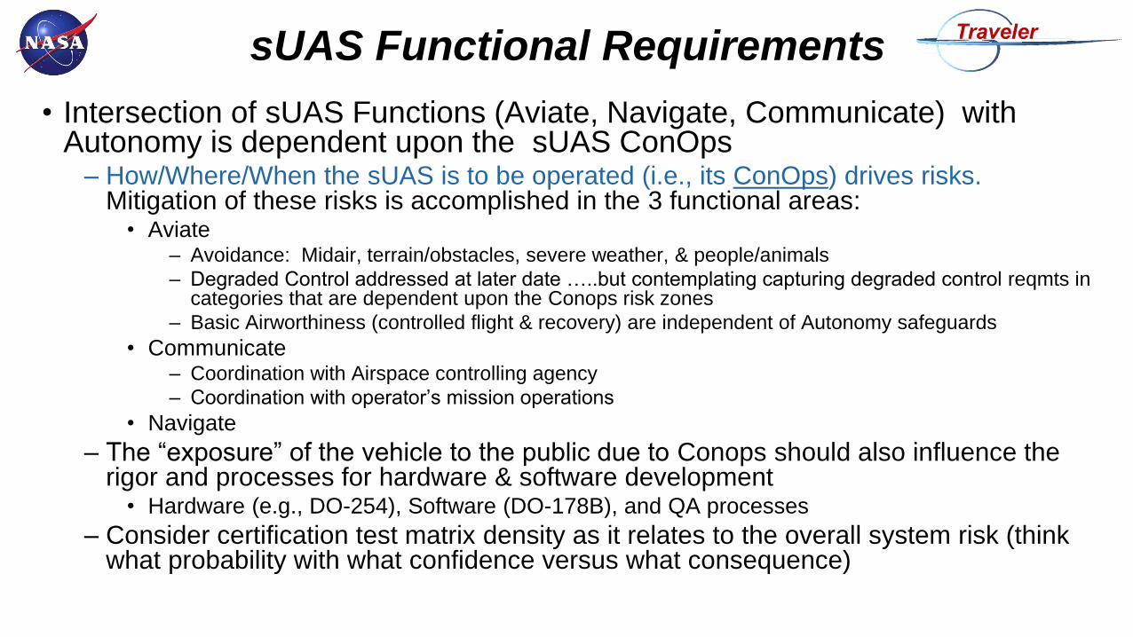
• Intersection of sUAS Functions (Aviate, Navigate, Communicate) with Autonomy is dependent upon the sUAS ConOps
– How/Where/When the sUAS is to be operated (i.e., its ConOps) drives risks. Mitigation of these risks is accomplished in the 3 functional areas:
• Aviate– Avoidance: Midair, terrain/obstacles, severe weather, & people/animals
– Degraded Control addressed at later date …..but contemplating capturing degraded control reqmts in categories that are dependent upon the Conops risk zones
– Basic Airworthiness (controlled flight & recovery) are independent of Autonomy safeguards
• Communicate– Coordination with Airspace controlling agency
– Coordination with operator’s mission operations
• Navigate
– The “exposure” of the vehicle to the public due to Conops should also influence the rigor and processes for hardware & software development
• Hardware (e.g., DO-254), Software (DO-178B), and QA processes
– Consider certification test matrix density as it relates to the overall system risk (think what probability with what confidence versus what consequence)
Midair Collision Avoidance
Terrain/Obstacle Avoidance
Severe Weather Avoidance
People/Animal Avoidance
FunctionsSystem
Reqmts
ConOps – Influences Upon sUAS Reqmts
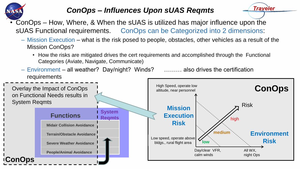
• ConOps – How, Where, & When the sUAS is utilized has major influence upon the
sUAS Functional requirements. ConOps can be Categorized into 2 dimensions:
– Mission Execution – what is the risk posed to people, obstacles, other vehicles as a result of the
Mission ConOps?
• How the risks are mitigated drives the cert requirements and accomplished through the Functional
Categories (Aviate, Navigate, Communicate)
– Environment – all weather? Day/night? Winds? ……… also drives the certification
requirements
Day/clear VFR,
calm winds
Mission
Execution
Risk
ConOps
All WX,
night Ops
Low speed, operate above
bldgs., rural flight area
High Speed, operate low
altitude, near personnel
Environment
Risk low
medium
high
Risk
Overlay the Impact of ConOps
on Functional Needs results in
System Reqmts
ConOps
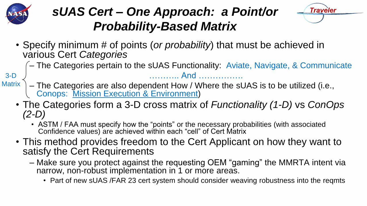
sUAS Cert – One Approach: a Point/or
Probability-Based Matrix
• Specify minimum # of points (or probability) that must be achieved in various Cert Categories
– The Categories pertain to the sUAS Functionality: Aviate, Navigate, & Communicate
……….. And …………….
– The Categories are also dependent How / Where the sUAS is to be utilized (i.e., Conops: Mission Execution & Environment)
• The Categories form a 3-D cross matrix of Functionality (1-D) vs ConOps(2-D)
• ASTM / FAA must specify how the “points” or the necessary probabilities (with associated Confidence values) are achieved within each “cell” of Cert Matrix
• This method provides freedom to the Cert Applicant on how they want to satisfy the Cert Requirements
– Make sure you protect against the requesting OEM “gaming” the MMRTA intent via narrow, non-robust implementation in 1 or more areas.
• Part of new sUAS /FAR 23 cert system should consider weaving robustness into the reqmts
3-D
Matrix
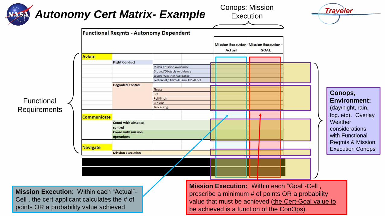
Autonomy Cert Matrix- Example
Functional
Requirements
Conops: Mission
Execution
Mission Execution: Within each “Goal”-Cell ,
prescribe a minimum # of points OR a probability
value that must be achieved (the Cert-Goal value to
be achieved is a function of the ConOps).
Mission Execution: Within each “Actual”-
Cell , the cert applicant calculates the # of
points OR a probability value achieved
Hardware Requirements
Software Development Processes
Conops,
Environment:(day/night, rain,
fog. etc): Overlay
Weather
considerations
with Functional
Reqmts & Mission
Execution Conops
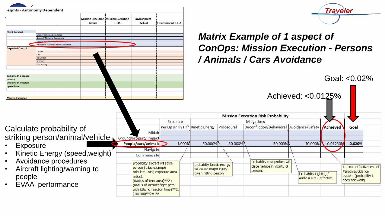
Matrix Example of 1 aspect of
ConOps: Mission Execution - Persons
/ Animals / Cars Avoidance
Calculate probability of striking person/animal/vehicle• Exposure• Kinetic Energy (speed,weight)• Avoidance procedures• Aircraft lighting/warning to
people• EVAA performance
Goal: <0.02%
Achieved: <0.0125%

Next Steps
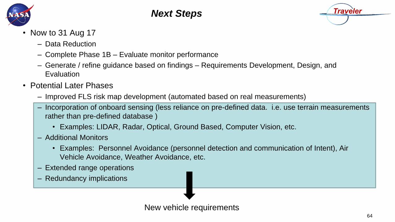
Next Steps
• Now to 31 Aug 17
– Data Reduction
– Complete Phase 1B – Evaluate monitor performance
– Generate / refine guidance based on findings – Requirements Development, Design, and
Evaluation
• Potential Later Phases
– Improved FLS risk map development (automated based on real measurements)
– Incorporation of onboard sensing (less reliance on pre-defined data. i.e. use terrain measurements
rather than pre-defined database )
• Examples: LIDAR, Radar, Optical, Ground Based, Computer Vision, etc.
– Additional Monitors
• Examples: Personnel Avoidance (personnel detection and communication of Intent), Air
Vehicle Avoidance, Weather Avoidance, etc.
– Extended range operations
– Redundancy implications
64
New vehicle requirements

Take Away
Take Away Points for Developing MMRTA
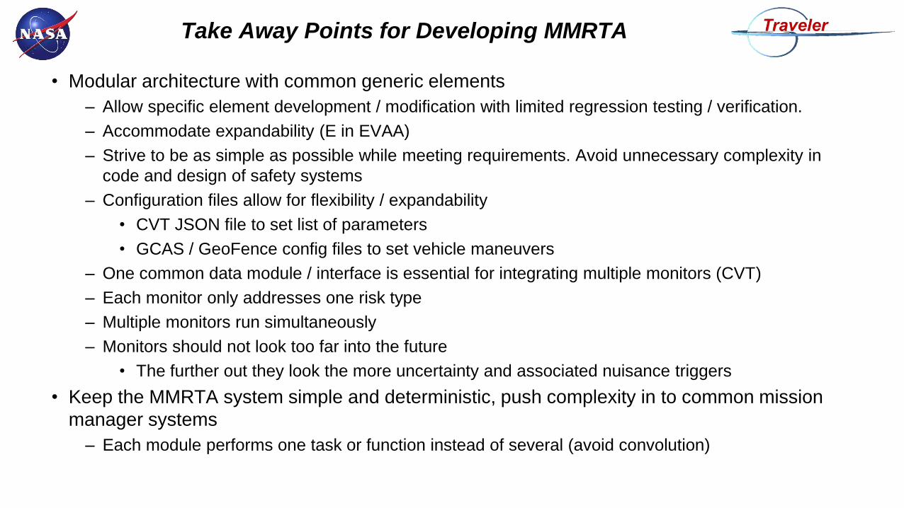
• Modular architecture with common generic elements
– Allow specific element development / modification with limited regression testing / verification.
– Accommodate expandability (E in EVAA)
– Strive to be as simple as possible while meeting requirements. Avoid unnecessary complexity in
code and design of safety systems
– Configuration files allow for flexibility / expandability
• CVT JSON file to set list of parameters
• GCAS / GeoFence config files to set vehicle maneuvers
– One common data module / interface is essential for integrating multiple monitors (CVT)
– Each monitor only addresses one risk type
– Multiple monitors run simultaneously
– Monitors should not look too far into the future
• The further out they look the more uncertainty and associated nuisance triggers
• Keep the MMRTA system simple and deterministic, push complexity in to common mission
manager systems
– Each module performs one task or function instead of several (avoid convolution)
Take Away Points for Developing MMRTA
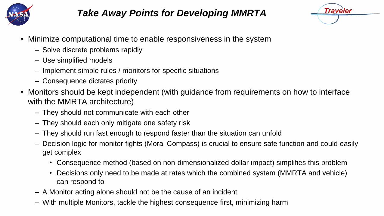
• Minimize computational time to enable responsiveness in the system
– Solve discrete problems rapidly
– Use simplified models
– Implement simple rules / monitors for specific situations
– Consequence dictates priority
• Monitors should be kept independent (with guidance from requirements on how to interface
with the MMRTA architecture)
– They should not communicate with each other
– They should each only mitigate one safety risk
– They should run fast enough to respond faster than the situation can unfold
– Decision logic for monitor fights (Moral Compass) is crucial to ensure safe function and could easily
get complex
• Consequence method (based on non-dimensionalized dollar impact) simplifies this problem
• Decisions only need to be made at rates which the combined system (MMRTA and vehicle)
can respond to
– A Monitor acting alone should not be the cause of an incident
– With multiple Monitors, tackle the highest consequence first, minimizing harm
Take Away Points for Developing MMRTA
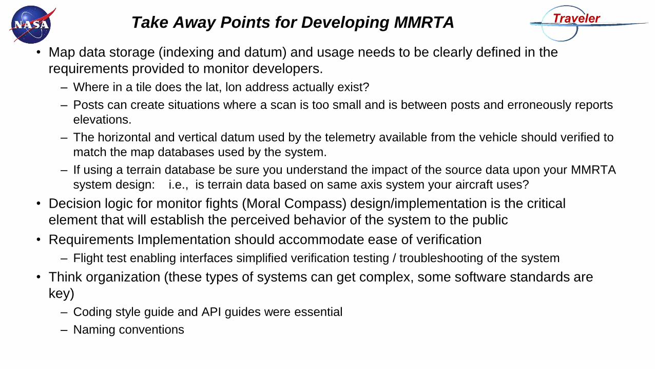
• Map data storage (indexing and datum) and usage needs to be clearly defined in the
requirements provided to monitor developers.
– Where in a tile does the lat, lon address actually exist?
– Posts can create situations where a scan is too small and is between posts and erroneously reports
elevations.
– The horizontal and vertical datum used by the telemetry available from the vehicle should verified to
match the map databases used by the system.
– If using a terrain database be sure you understand the impact of the source data upon your MMRTA
system design: i.e., is terrain data based on same axis system your aircraft uses?
• Decision logic for monitor fights (Moral Compass) design/implementation is the critical
element that will establish the perceived behavior of the system to the public
• Requirements Implementation should accommodate ease of verification
– Flight test enabling interfaces simplified verification testing / troubleshooting of the system
• Think organization (these types of systems can get complex, some software standards are
key)
– Coding style guide and API guides were essential
– Naming conventions
Take Away Points for Developing MMRTA
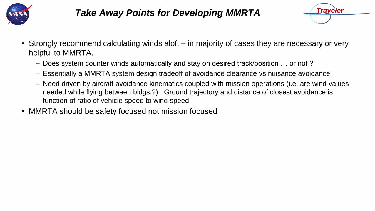
• Strongly recommend calculating winds aloft – in majority of cases they are necessary or very
helpful to MMRTA.
– Does system counter winds automatically and stay on desired track/position … or not ?
– Essentially a MMRTA system design tradeoff of avoidance clearance vs nuisance avoidance
– Need driven by aircraft avoidance kinematics coupled with mission operations (i.e, are wind values
needed while flying between bldgs.?) Ground trajectory and distance of closest avoidance is
function of ratio of vehicle speed to wind speed
• MMRTA should be safety focused not mission focused
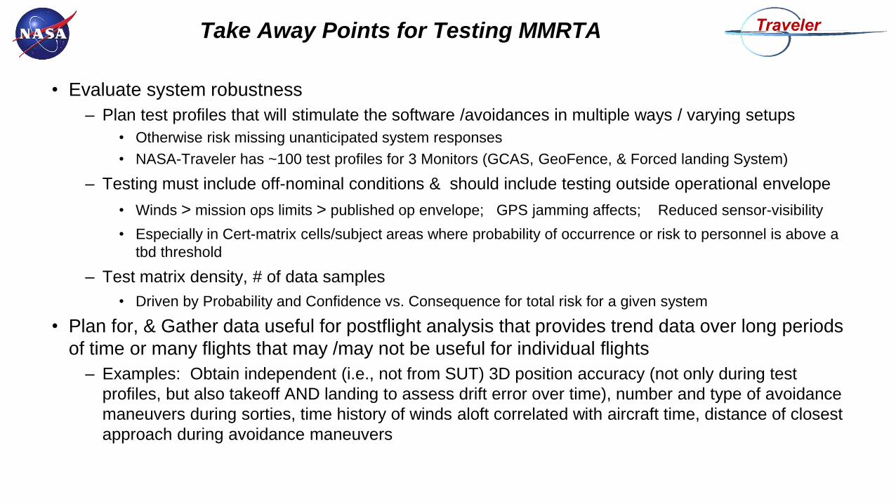
Take Away Points for Testing MMRTA
• Evaluate system robustness
– Plan test profiles that will stimulate the software /avoidances in multiple ways / varying setups
• Otherwise risk missing unanticipated system responses
• NASA-Traveler has ~100 test profiles for 3 Monitors (GCAS, GeoFence, & Forced landing System)
– Testing must include off-nominal conditions & should include testing outside operational envelope
• Winds > mission ops limits > published op envelope; GPS jamming affects; Reduced sensor-visibility
• Especially in Cert-matrix cells/subject areas where probability of occurrence or risk to personnel is above a
tbd threshold
– Test matrix density, # of data samples
• Driven by Probability and Confidence vs. Consequence for total risk for a given system
• Plan for, & Gather data useful for postflight analysis that provides trend data over long periods
of time or many flights that may /may not be useful for individual flights
– Examples: Obtain independent (i.e., not from SUT) 3D position accuracy (not only during test
profiles, but also takeoff AND landing to assess drift error over time), number and type of avoidance
maneuvers during sorties, time history of winds aloft correlated with aircraft time, distance of closest
approach during avoidance maneuvers
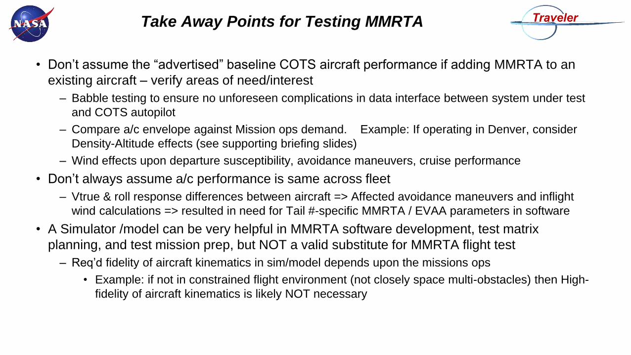
Take Away Points for Testing MMRTA
• Don’t assume the “advertised” baseline COTS aircraft performance if adding MMRTA to an
existing aircraft – verify areas of need/interest
– Babble testing to ensure no unforeseen complications in data interface between system under test
and COTS autopilot
– Compare a/c envelope against Mission ops demand. Example: If operating in Denver, consider
Density-Altitude effects (see supporting briefing slides)
– Wind effects upon departure susceptibility, avoidance maneuvers, cruise performance
• Don’t always assume a/c performance is same across fleet
– Vtrue & roll response differences between aircraft => Affected avoidance maneuvers and inflight
wind calculations => resulted in need for Tail #-specific MMRTA / EVAA parameters in software
• A Simulator /model can be very helpful in MMRTA software development, test matrix
planning, and test mission prep, but NOT a valid substitute for MMRTA flight test
– Req’d fidelity of aircraft kinematics in sim/model depends upon the missions ops
• Example: if not in constrained flight environment (not closely space multi-obstacles) then High-
fidelity of aircraft kinematics is likely NOT necessary
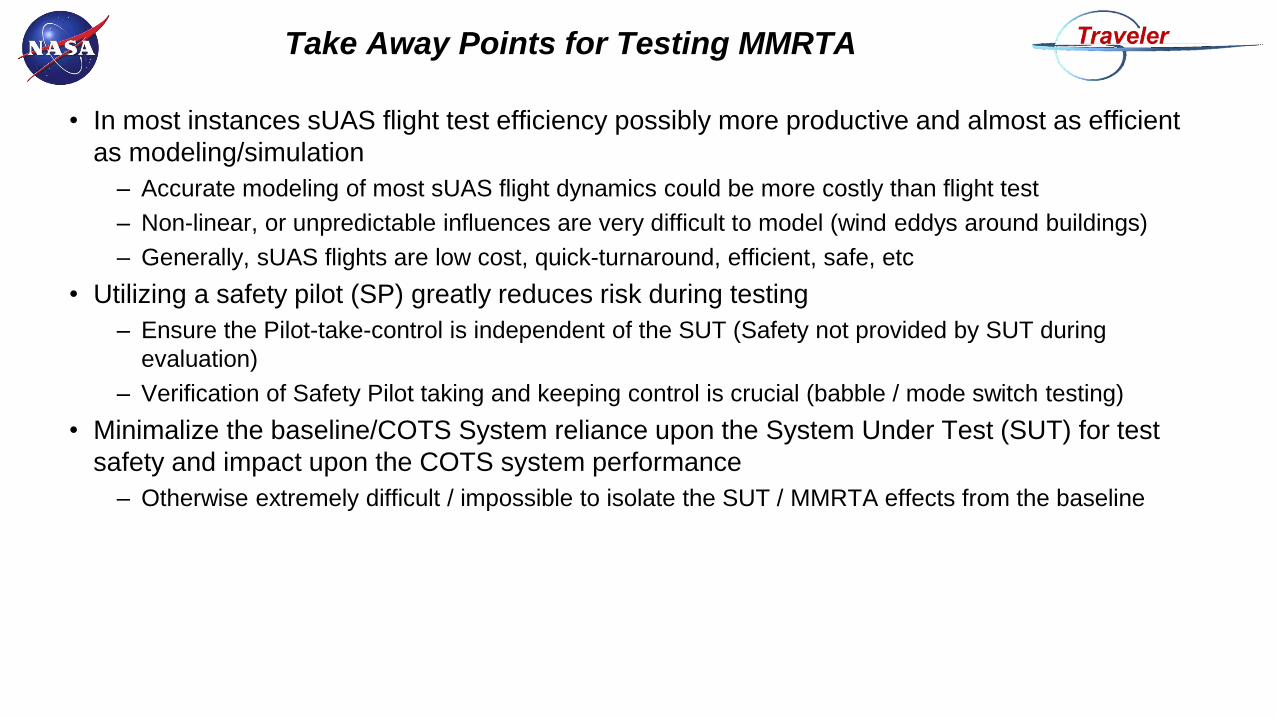
Take Away Points for Testing MMRTA
• In most instances sUAS flight test efficiency possibly more productive and almost as efficient
as modeling/simulation
– Accurate modeling of most sUAS flight dynamics could be more costly than flight test
– Non-linear, or unpredictable influences are very difficult to model (wind eddys around buildings)
– Generally, sUAS flights are low cost, quick-turnaround, efficient, safe, etc
• Utilizing a safety pilot (SP) greatly reduces risk during testing
– Ensure the Pilot-take-control is independent of the SUT (Safety not provided by SUT during
evaluation)
– Verification of Safety Pilot taking and keeping control is crucial (babble / mode switch testing)
• Minimalize the baseline/COTS System reliance upon the System Under Test (SUT) for test
safety and impact upon the COTS system performance
– Otherwise extremely difficult / impossible to isolate the SUT / MMRTA effects from the baseline

Backup
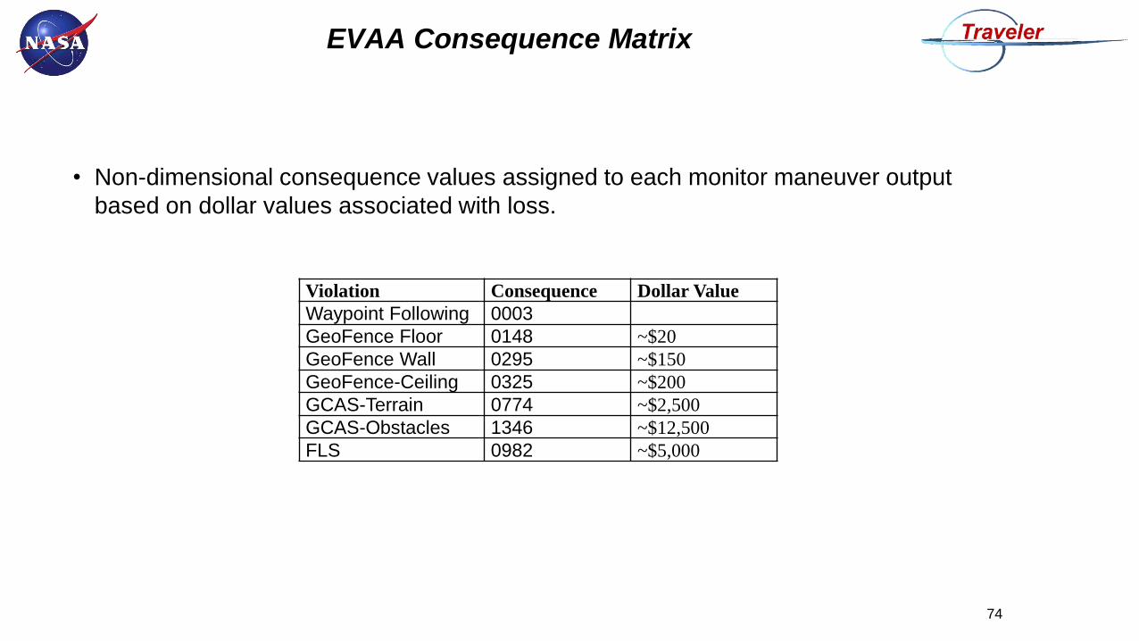
EVAA Consequence Matrix
• Non-dimensional consequence values assigned to each monitor maneuver output
based on dollar values associated with loss.
Violation Consequence Dollar Value
Waypoint Following 0003
GeoFence Floor 0148 ~$20
GeoFence Wall 0295 ~$150
GeoFence-Ceiling 0325 ~$200
GCAS-Terrain 0774 ~$2,500
GCAS-Obstacles 1346 ~$12,500
FLS 0982 ~$5,000
74
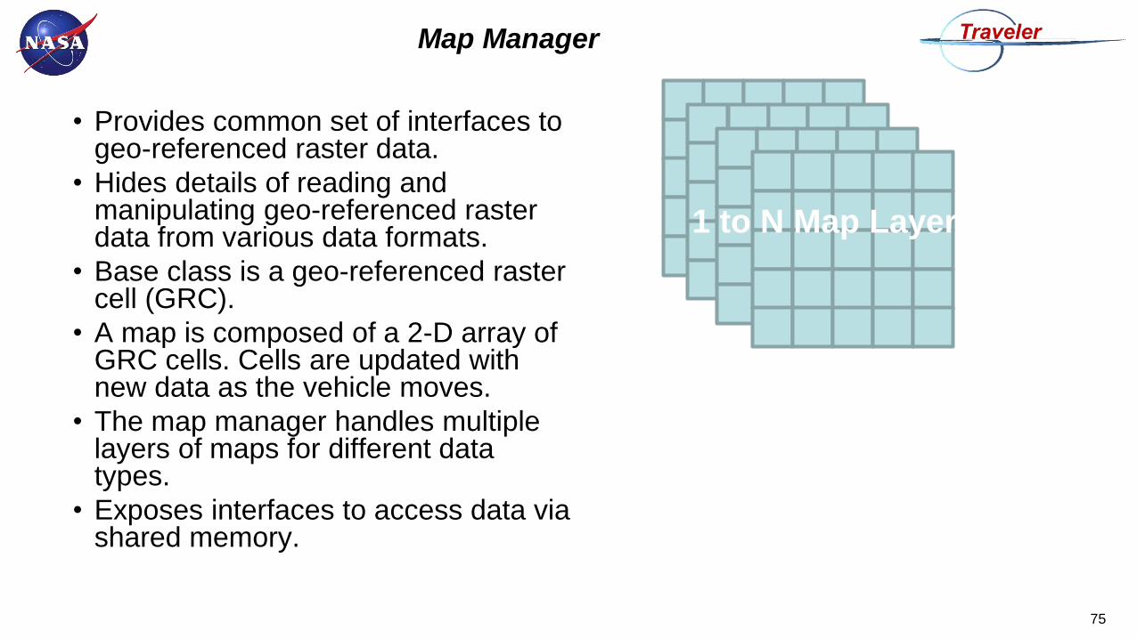
Map Manager
• Provides common set of interfaces to geo-referenced raster data.
• Hides details of reading and manipulating geo-referenced raster data from various data formats.
• Base class is a geo-referenced raster cell (GRC).
• A map is composed of a 2-D array of GRC cells. Cells are updated with new data as the vehicle moves.
• The map manager handles multiple layers of maps for different data types.
• Exposes interfaces to access data via shared memory.
75
1 to N Map Layers
Map Manager Can Read Multiple File Types
• CDTM – Compressed Digital Terrain Map (NASA format)
– Highly compressed into tiles. Decompressed and re-rasterized.
– Is not lossless compression. Error limits are imposed on map compression based on end-user
requirements.
– Typically rasterize to same resolution as source data.
• “Feature Data” – project-specific XML format.
– Easy for user to hand-edit file to add features such as power-lines, buildings, obstacles of various
heights and shapes.
• “Format19” – Project-specific 1/9 arc second raster format.
– Will be used to hold obstacle data generated from LiDAR data.
• DTED – DOD Digital Terrain Elevation Data format
– Level 2 – 1 arc second resolution, integer elevation (meters)
• NED – National Elevation Data
– 1/3 arc second resolution, floating point
76
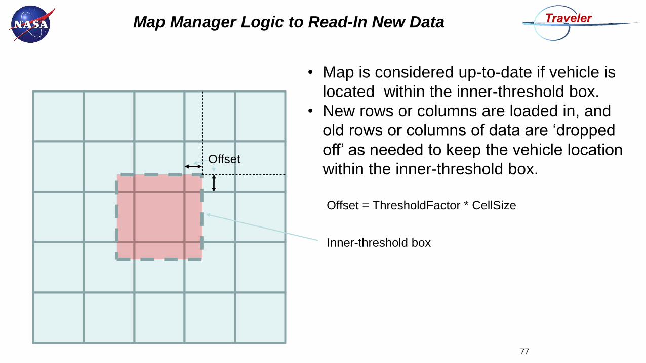
Map Manager Logic to Read-In New Data
77
Offset = ThresholdFactor * CellSize
Inner-threshold box
Offset
• Map is considered up-to-date if vehicle is
located within the inner-threshold box.
• New rows or columns are loaded in, and
old rows or columns of data are ‘dropped
off’ as needed to keep the vehicle location
within the inner-threshold box.
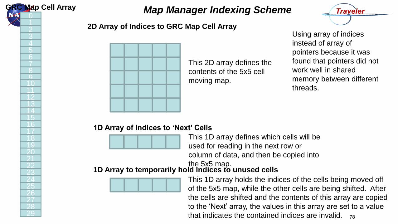
Map Manager Indexing Scheme
78
01234567891011121314151617181920212223242526272829
GRC Map Cell Array
2D Array of Indices to GRC Map Cell Array
This 2D array defines the
contents of the 5x5 cell
moving map.
1D Array of Indices to ‘Next’ Cells
1D Array to temporarily hold Indices to unused cells
This 1D array defines which cells will be
used for reading in the next row or
column of data, and then be copied into
the 5x5 map.
This 1D array holds the indices of the cells being moved off
of the 5x5 map, while the other cells are being shifted. After
the cells are shifted and the contents of this array are copied
to the ‘Next’ array, the values in this array are set to a value
that indicates the contained indices are invalid.
Using array of indices
instead of array of
pointers because it was
found that pointers did not
work well in shared
memory between different
threads.
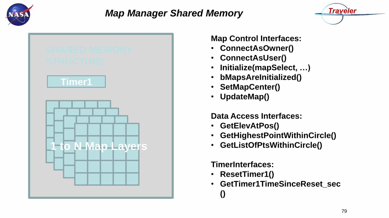
Map Manager Shared Memory
79
1 to N Map Layers
Timer1
Map Control Interfaces:
• ConnectAsOwner()
• ConnectAsUser()
• Initialize(mapSelect, …)
• bMapsAreInitialized()
• SetMapCenter()
• UpdateMap()
Data Access Interfaces:
• GetElevAtPos()
• GetHighestPointWithinCircle()
• GetListOfPtsWithinCircle()
TimerInterfaces:
• ResetTimer1()
• GetTimer1TimeSinceReset_sec
()
SHARED MEMORY
STRUCTURE
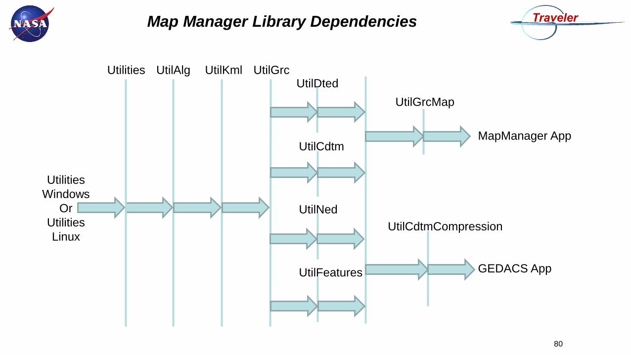
Map Manager Library Dependencies
80
UtilAlg UtilGrcUtilDted
UtilCdtm
UtilNed
UtilFeatures
UtilGrcMap
Utilities UtilKml
Utilities
Windows
Or
Utilities
LinuxUtilCdtmCompression
MapManager App
GEDACS App
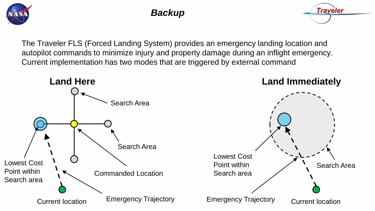
Backup
The Traveler FLS (Forced Landing System) provides an emergency landing location and
autopilot commands to minimize injury and property damage during an inflight emergency.
Current implementation has two modes that are triggered by external command
Land Here
Current location
Commanded LocationSearch AreaLowest Cost
Point within
Search area
Emergency Trajectory
Land Immediately
Current locationEmergency Trajectory
Lowest Cost
Point within
Search area
Search Area
Search Area
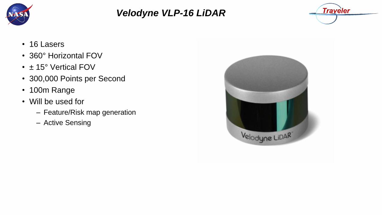
Velodyne VLP-16 LiDAR
• 16 Lasers
• 360° Horizontal FOV
• ± 15° Vertical FOV
• 300,000 Points per Second
• 100m Range
• Will be used for
– Feature/Risk map generation
– Active Sensing
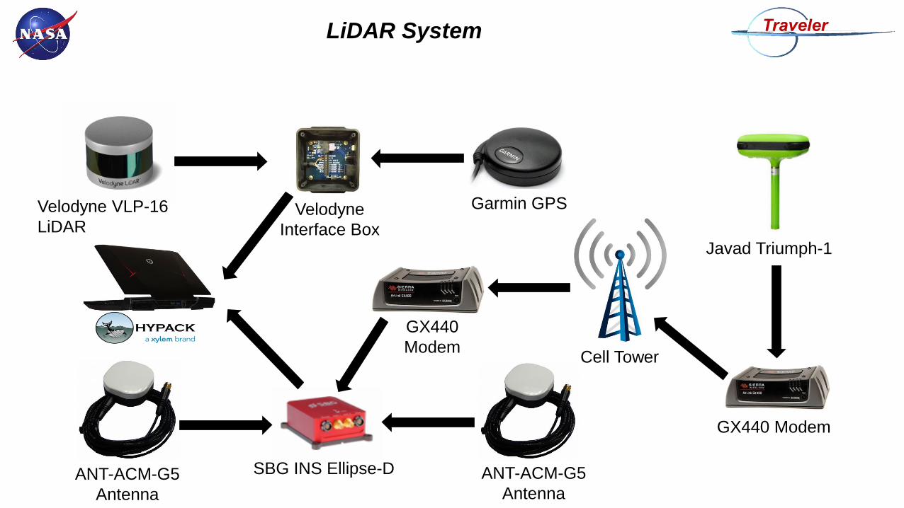
LiDAR System
Velodyne VLP-16
LiDARVelodyne
Interface Box
Garmin GPS
Javad Triumph-1
GX440 Modem
SBG INS Ellipse-D ANT-ACM-G5
Antenna
Cell Tower
ANT-ACM-G5
Antenna
GX440
Modem
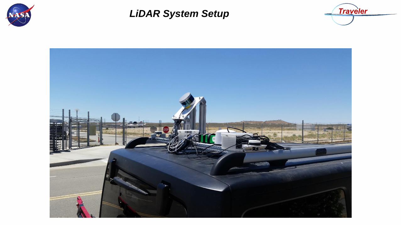
LiDAR System Setup
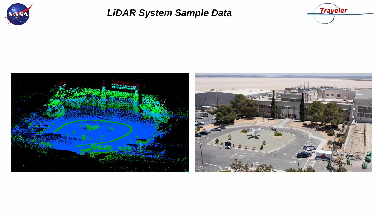
LiDAR System Sample Data
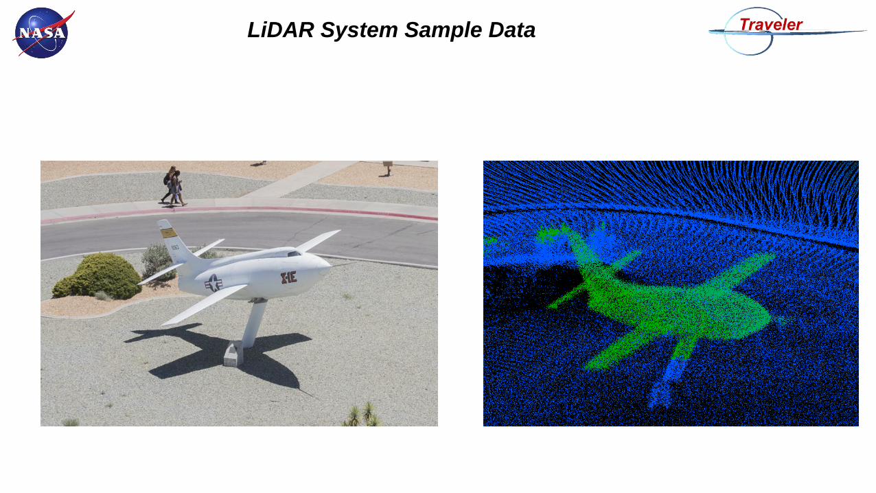
LiDAR System Sample Data