Embed Size (px)
Citation preview
DESCRIPTION
The TruStability Standard Accuracy Silicon Ceramic (SSC)
Series is a piezoresistive silicon pressure sensor offering a
digital output for reading pressure over the specified full scale
pressure span and temperature range.
The SSC Series is fully calibrated and temperature
compensated for sensor offset, sensitivity, temperature effects,
and non-linearity using an on-board Application Specific
Integrated Circuit (ASIC). Calibrated output values for pressure
are updated at approximately 2 kHz.
The SSC Series is calibrated over the temperature range of
-20 C to 85 C [-4 F to 185 F]. The sensor is characterized
for operation from a single power supply of either 3.3 Vdc or
5.0 Vdc.
These sensors measure absolute, differential, and gage
pressures. The absolute versions have an internal vacuum
reference and an output value proportional to absolute
pressure. Differential versions allow application of pressure to
either side of the sensing diaphragm. Gage versions are
referenced to atmospheric pressure and provide an output
proportional to pressure variations from atmosphere.
The TruStability® pressure sensors are intended for use with
non-corrosive, non-ionic gases, such as air and other dry
gases. An available option extends the performance of these
sensors to non-corrosive, non-ionic liquids.
All products are designed and manufactured according to ISO
9001 standards.
FEATURES
Industry-leading long-term stability
Extremely tight accuracy of 0.25% FSS BFSL (Full Scale
Span Best Fit Straight Line)
Total error band of 2% full scale span maximum
Modular and flexible design offers customers a variety of
package styles and options, all with the same industry-
leading performance specifications
Miniature 10 mm x 10 mm [0.39 in x 0.39 in] package
Low operating voltage
Extremely low power consumption
I2C- or SPI- compatible 14-bit digital output (min. 12-bit
sensor resolution)
Precision ASIC conditioning and temperature compensated
over -20 C to 85 C [-4 F to 185 F] temperature range
RoHS compliant
Virtually insensitive to mounting orientation
Internal diagnostic functions increase system reliability
Also available with analog output
Absolute, differential, and gage types
Pressure ranges from 1 psi to 150 psi (60 mbar to 10 bar)
Custom calibration available
Various pressure port options
Liquid media option
2 www.honeywell.com/sensing
POTENTIAL APPLICATIONS
Medical:
- Airflow monitors
- Anesthesia machines
- Blood analysis machines
- Gas chromatography
- Gas flow instrumentation
- Kidney dialysis machines
- Oxygen concentrators
- Pneumatic controls
- Respiratory machines
- Sleep apnea equipment
- Ventilators
Industrial:
- Barometry
- Flow calibrators
- Gas chromatography
- Gas flow instrumentation
- HVAC
- Life sciences
- Pneumatic controls
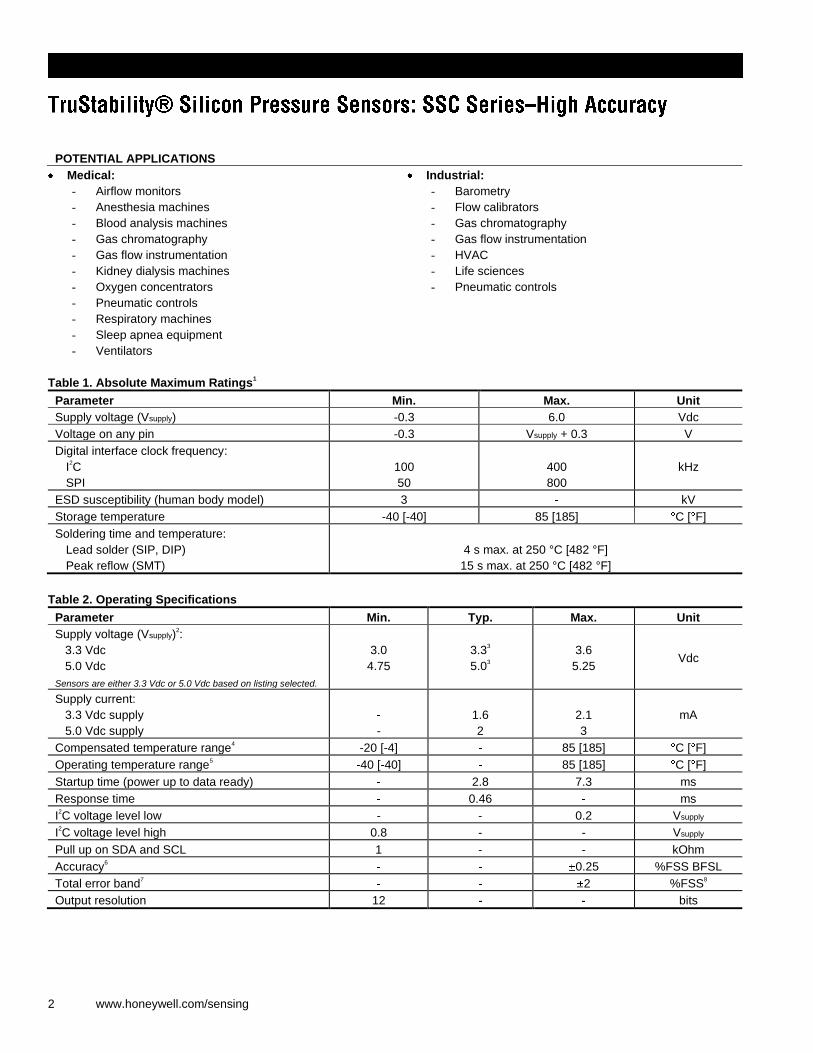
Table 1. Absolute Maximum Ratings1
Parameter Min. Max. Unit
Supply voltage (Vsupply) -0.3 6.0 Vdc
Voltage on any pin -0.3 Vsupply + 0.3 V
Digital interface clock frequency:
I2C
SPI
100
50
400
800
kHz
ESD susceptibility (human body model) 3 kV
Storage temperature -40 [-40] 85 [185] C [ F]
Soldering time and temperature:
Lead solder (SIP, DIP)
Peak reflow (SMT)
4 s max. at 250 °C [482 °F]
15 s max. at 250 °C [482 °F]
Table 2. Operating Specifications
Parameter Min. Typ. Max. Unit
Supply voltage (Vsupply)2:
3.3 Vdc
5.0 Vdc
Sensors are either 3.3 Vdc or 5.0 Vdc based on listing selected.
3.0
4.75
3.33
5.03
3.6
5.25 Vdc
Supply current:
3.3 Vdc supply
5.0 Vdc supply
-
1.6
2
2.1
3
mA
Compensated temperature range4 -20 [-4] 85 [185] C [ F]
Operating temperature range5 -40 [-40] 85 [185] C [ F]
Startup time (power up to data ready) 2.8 7.3 ms
Response time 0.46 ms
I2C voltage level low - - 0.2 Vsupply
I2C voltage level high 0.8 - - Vsupply
Pull up on SDA and SCL 1 - - kOhm
Accuracy6 0.25 %FSS BFSL
Total error band7 2 %FSS
8
Output resolution 12 bits
Honeywell Sensing and Control 3
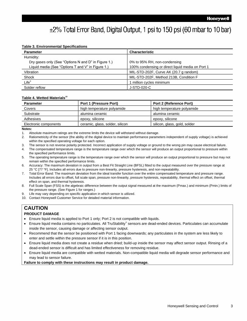
Table 3. Environmental Specifications
Parameter Characteristic
Humidity:
Dry gases only (See “Options N and D” in Figure 1.)
Liquid media (See “Options T and V” in Figure 1.)
0% to 95% RH, non-condensing
100% condensing or direct liquid media on Port 1
Vibration MIL-STD-202F, Curve AK (20.7 g random)
Shock MIL-STD-202F, Method 213B, Condition F
Life9 1 million cycles minimum
Solder reflow J-STD-020-C
Table 4. Wetted Materials10
Parameter Port 1 (Pressure Port) Port 2 (Reference Port)
Covers high temperature polyamide high temperature polyamide
Substrate alumina ceramic alumina ceramic
Adhesives epoxy, silicone epoxy, silicone
Electronic components ceramic, glass, solder, silicon silicon, glass, gold, solder
Notes:
1. Absolute maximum ratings are the extreme limits the device will withstand without damage.
2. Ratiometricity of the sensor (the ability of the digital device to maintain performance parameters independent of supply voltage) is achieved
within the specified operating voltage for each option.
3. The sensor is not reverse polarity protected. Incorrect application of supply voltage or ground to the wrong pin may cause electrical failure.
4. The compensated temperature range is the temperature range over which the sensor will produce an output proportional to pressure within
the specified performance limits.
5. The operating temperature range is the temperature range over which the sensor will produce an output proportional to pressure but may not
remain within the specified performance limits.
6. Accuracy: The maximum deviation in output from a Best Fit Straight Line (BFSL) fitted to the output measured over the pressure range at
25 °C [77 °F]. Includes all errors due to pressure non-linearity, pressure hysteresis, and non-repeatability.
7. Total Error Band: The maximum deviation from the ideal transfer function over the entire compensated temperature and pressure range.
Includes all errors due to offset, full scale span, pressure non-linearity, pressure hysteresis, repeatability, thermal effect on offset, thermal
effect on span, and thermal hysteresis.
8. Full Scale Span (FSS) is the algebraic difference between the output signal measured at the maximum (Pmax.) and minimum (Pmin.) limits of
the pressure range. (See Figure 1 for ranges.)
9. Life may vary depending on specific application in which sensor is utilized.
10. Contact Honeywell Customer Service for detailed material information.
CAUTION PRODUCT DAMAGE
Ensure liquid media is applied to Port 1 only; Port 2 is not compatible with liquids.
Ensure liquid media contains no particulates. All TruStability® sensors are dead-ended devices. Particulates can accumulate
inside the sensor, causing damage or affecting sensor output.
Recommend that the sensor be positioned with Port 1 facing downwards; any particulates in the system are less likely to
enter and settle within the pressure sensor if it is in this position.
Ensure liquid media does not create a residue when dried; build-up inside the sensor may affect sensor output. Rinsing of a
dead-ended sensor is difficult and has limited effectiveness for removing residue.
Ensure liquid media are compatible with wetted materials. Non-compatible liquid media will degrade sensor performance and
may lead to sensor failure.
Failure to comply with these instructions may result in product damage.
4 www.honeywell.com/sensing
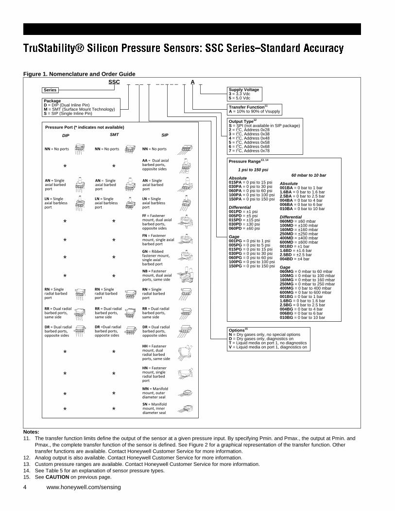
Figure 1. Nomenclature and Order Guide
Series
PackageD = DIP (Dual Inline Pin)M = SMT (Surface Mount Technology)S = SIP (Single Inline Pin)
Transfer Function11
A = 10% to 90% of Vsupply
Output Type12
S = SPI (not available in SIP package) 2 = I
2C, Address 0x28
3 = I2C, Address 0x38
4 = I2C, Address 0x48
5 = I2C, Address 0x58
6 = I2C, Address 0x68
7 = I2C, Address 0x78
SSC _ _ _ _ _ _ _ _ _ _A_
Supply Voltage3 = 3.3 Vdc5 = 5.0 Vdc
Pressure Range13, 14
1 psi to 150 psi
Absolute015PA = 0 psi to 15 psi030PA = 0 psi to 30 psi060PA = 0 psi to 60 psi100PA = 0 psi to 100 psi150PA = 0 psi to 150 psi
Differential001PD = ±1 psi005PD = ±5 psi015PD = ±15 psi030PD = ±30 psi060PD = ±60 psi
Gage001PG = 0 psi to 1 psi005PG = 0 psi to 5 psi015PG = 0 psi to 15 psi030PG = 0 psi to 30 psi060PG = 0 psi to 60 psi100PG = 0 psi to 100 psi150PG = 0 psi to 150 psi
60 mbar to 10 bar
Absolute001BA = 0 bar to 1 bar1.6BA = 0 bar to 1.6 bar2.5BA = 0 bar to 2.5 bar004BA = 0 bar to 4 bar006BA = 0 bar to 6 bar010BA = 0 bar to 10 bar
Differential060MD = ±60 mbar100MD = ±100 mbar160MD = ±160 mbar250MD = ±250 mbar400MD = ±400 mbar600MD = ±600 mbar001BD = ±1 bar1.6BD = ±1.6 bar2.5BD = ±2.5 bar004BD = ±4 bar
Gage060MG = 0 mbar to 60 mbar100MG = 0 mbar to 100 mbar160MG = 0 mbar to 160 mbar250MG = 0 mbar to 250 mbar400MG = 0 bar to 400 mbar600MG = 0 bar to 600 mbar001BG = 0 bar to 1 bar1.6BG = 0 bar to 1.6 bar2.5BG = 0 bar to 2.5 bar004BG = 0 bar to 4 bar006BG = 0 bar to 6 bar010BG = 0 bar to 10 bar
Options15
N = Dry gases only, no special optionsD = Dry gases only, diagnostics onT = Liquid media on port 1, no diagnosticsV = Liquid media on port 1, diagnostics on
AA = Dual axial barbed ports, opposite sides
DIP
AN = Single axial barbed port
DR = Dual radial barbed ports, opposite sides
FF = Fastener mount, dual axial barbed ports, opposite sides
FN = Fastener mount, single axial barbed port
HH = Fastener mount, dual radial barbed ports, same side
HN = Fastener mount, single radial barbed port
MN = Manifold mount, outer diameter seal
LN = Single axial barbless port
NB = Fastener mount, dual axial ports, same side
NN = No ports
RN = Single radial barbed port
RR = Dual radial barbed ports, same side
SN = Manifold mount, inner diameter seal
Pressure Port (* indicates not available)
SMT SIP
AN = Single axial barbed port
AN = Single axial barbed port
DR = Dual radial barbed ports, opposite sides
DR =Dual radial barbed ports, opposite sides
LN = Single axial barbless port
RN = Single radial barbed port
RN = Single radial barbed port
RR = Dual radial barbed ports, same side
RR = Dual radial barbed ports, same side
NN = No ports NN = No ports
LN = Single axial barbless port
* *
* *
* *
* *
* *
* *
* *
* *
* *
GN = Ribbed fastener mount, single axial barbed port
Notes:
11. The transfer function limits define the output of the sensor at a given pressure input. By specifying Pmin. and Pmax., the output at Pmin. and
Pmax., the complete transfer function of the sensor is defined. See Figure 2 for a graphical representation of the transfer function. Other
transfer functions are available. Contact Honeywell Customer Service for more information.
12. Analog output is also available. Contact Honeywell Customer Service for more information.
13. Custom pressure ranges are available. Contact Honeywell Customer Service for more information.
14. See Table 5 for an explanation of sensor pressure types.
15. See CAUTION on previous page.
Honeywell Sensing and Control 5
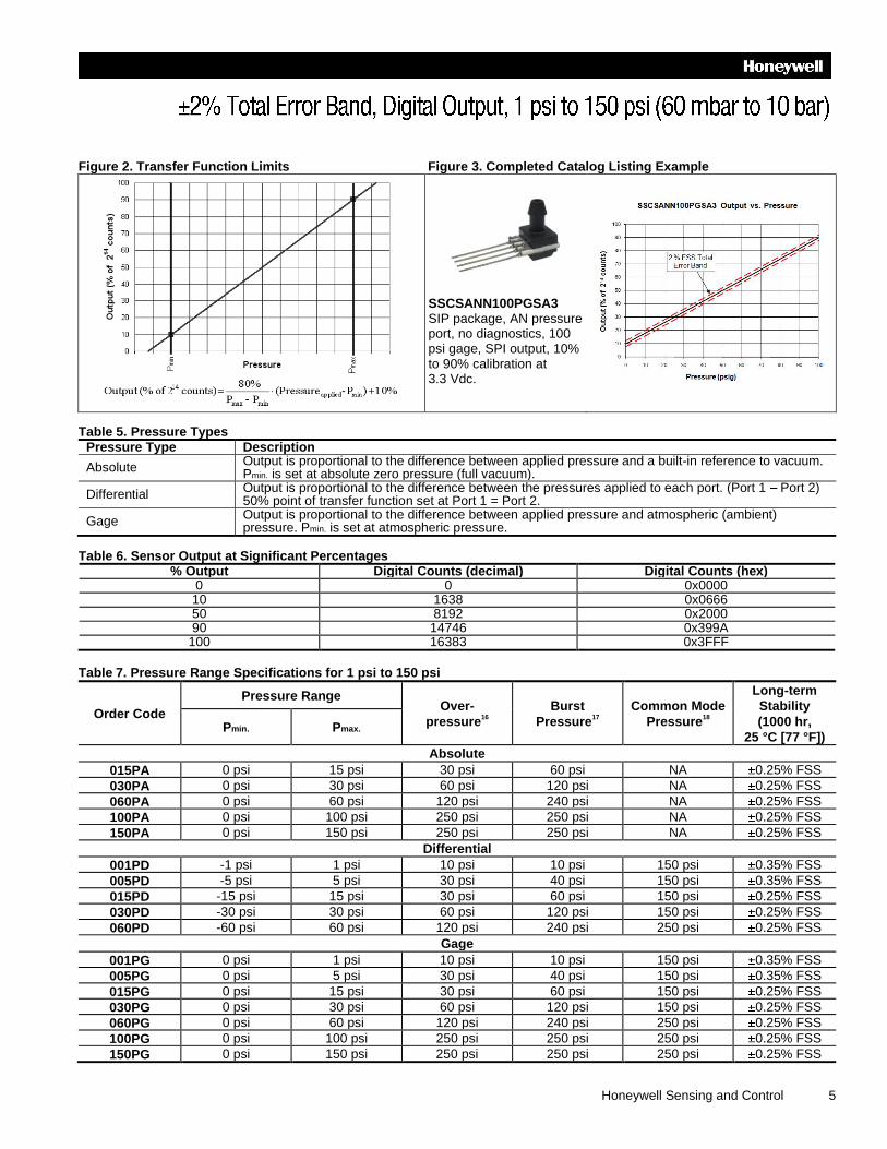
Figure 2. Transfer Function Limits Figure 3. Completed Catalog Listing Example
SSCSANN100PGSA3 SIP package, AN pressure port, no diagnostics, 100 psi gage, SPI output, 10% to 90% calibration at 3.3 Vdc.
Table 5. Pressure Types
Pressure Type Description
Absolute Output is proportional to the difference between applied pressure and a built-in reference to vacuum. Pmin. is set at absolute zero pressure (full vacuum).
Differential Output is proportional to the difference between the pressures applied to each port. (Port 1 Port 2) 50% point of transfer function set at Port 1 = Port 2.
Gage Output is proportional to the difference between applied pressure and atmospheric (ambient) pressure. Pmin. is set at atmospheric pressure.
Table 6. Sensor Output at Significant Percentages
% Output Digital Counts (decimal) Digital Counts (hex) 0 0 0x0000 10 1638 0x0666 50 8192 0x2000 90 14746 0x399A
100 16383 0x3FFF
Table 7. Pressure Range Specifications for 1 psi to 150 psi
Order Code
Pressure Range Over-
pressure16
Burst
Pressure17
Common Mode
Pressure18
Long-term
Stability
(1000 hr,
25 °C [77 °F]) Pmin. Pmax.
Absolute
015PA 0 psi 15 psi 30 psi 60 psi NA 0.25% FSS
030PA 0 psi 30 psi 60 psi 120 psi NA 0.25% FSS
060PA 0 psi 60 psi 120 psi 240 psi NA 0.25% FSS
100PA 0 psi 100 psi 250 psi 250 psi NA 0.25% FSS
150PA 0 psi 150 psi 250 psi 250 psi NA 0.25% FSS
Differential
001PD -1 psi 1 psi 10 psi 10 psi 150 psi 0.35% FSS
005PD -5 psi 5 psi 30 psi 40 psi 150 psi 0.35% FSS
015PD -15 psi 15 psi 30 psi 60 psi 150 psi 0.25% FSS
030PD -30 psi 30 psi 60 psi 120 psi 150 psi 0.25% FSS
060PD -60 psi 60 psi 120 psi 240 psi 250 psi 0.25% FSS
Gage
001PG 0 psi 1 psi 10 psi 10 psi 150 psi 0.35% FSS
005PG 0 psi 5 psi 30 psi 40 psi 150 psi 0.35% FSS
015PG 0 psi 15 psi 30 psi 60 psi 150 psi 0.25% FSS
030PG 0 psi 30 psi 60 psi 120 psi 150 psi 0.25% FSS
060PG 0 psi 60 psi 120 psi 240 psi 250 psi 0.25% FSS
100PG 0 psi 100 psi 250 psi 250 psi 250 psi 0.25% FSS
150PG 0 psi 150 psi 250 psi 250 psi 250 psi 0.25% FSS
6 www.honeywell.com/sensing
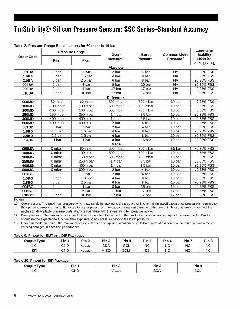
Table 8. Pressure Range Specifications for 60 mbar to 10 bar
Order Code
Pressure Range Over-
pressure16
Burst
Pressure17
Common Mode
Pressure18
Long-term
Stability
(1000 hr,
25 C [77 F]) Pmin. Pmax.
Absolute
001BA 0 bar 1 bar 2 bar 4 bar NA 0.25% FSS
1.6BA 0 bar 1.6 bar 4 bar 8 bar NA 0.25% FSS
2.5BA 0 bar 2.5 bar 6 bar 8 bar NA 0.25% FSS
004BA 0 bar 4 bar 8 bar 16 bar NA 0.25% FSS
006BA 0 bar 6 bar 17 bar 17 bar NA 0.25% FSS
010BA 0 bar 10 bar 17 bar 17 bar NA 0.25% FSS
Differential
060MD -60 mbar 60 mbar 500 mbar 700 mbar 10 bar 0.35% FSS
100MD -100 mbar 100 mbar 500 mbar 700 mbar 10 bar 0.35% FSS
160MD -160 mbar 160 mbar 500 mbar 700 mbar 10 bar 0.35% FSS
250MD -250 mbar 250 mbar 1.4 bar 2.5 bar 10 bar 0.35% FSS
400MD -400 mbar 400 mbar 1.4 bar 2.5 bar 10 bar 0.35% FSS
600MD -600 mbar 600 mbar 2 bar 4 bar 10 bar 0.25% FSS
001BD -1 bar 1 bar 2 bar 4 bar 10 bar 0.25% FSS
1.6BD -1.6 bar 1.6 bar 4 bar 8 bar 10 bar 0.25% FSS
2.5BD -2.5 bar 2.5 bar 6 bar 8 bar 10 bar 0.25% FSS
004BD -4 bar 4 bar 8 bar 16 bar 10 bar 0.25% FSS
Gage
060MG 0 mbar 60 mbar 500 mbar 700 mbar 3.5 bar 0.35% FSS
100MG 0 mbar 100 mbar 500 mbar 700 mbar 10 bar 0.35% FSS
160MG 0 mbar 160 mbar 500 mbar 700 mbar 10 bar 0.35% FSS
250MG 0 mbar 250 mbar 1.4 bar 2.5 bar 10 bar 0.35% FSS
400MG 0 mbar 400 mbar 1.4 bar 2.5 bar 10 bar 0.35% FSS
600MG 0 mbar 600 mbar 2 bar 4 bar 10 bar 0.35% FSS
001BG 0 bar 1 bar 2 bar 4 bar 10 bar 0.25% FSS
1.6BG 0 bar 1.6 bar 4 bar 8 bar 10 bar 0.25% FSS
2.5BG 0 bar 2.5 bar 6 bar 8 bar 10 bar 0.25% FSS
004BG 0 bar 4 bar 8 bar 16 bar 16 bar 0.25% FSS
006BG 0 bar 6 bar 17 bar 17 bar 17 bar 0.25% FSS
010BG 0 bar 10 bar 17 bar 17 bar 17 bar 0.25% FSS
Notes:
16. Overpressure: The maximum pressure which may safely be applied to the product for it to remain in specification once pressure is returned to
the operating pressure range. Exposure to higher pressures may cause permanent damage to the product. Unless otherwise specified this
applies to all available pressure ports at any temperature with the operating temperature range.
17. Burst pressure: The maximum pressure that may be applied to any port of the product without causing escape of pressure media. Product
should not be expected to function after exposure to any pressure beyond the burst pressure.
18. Common mode pressure: The maximum pressure that can be applied simultaneously to both ports of a differential pressure sensor without
causing changes in specified performance.
Table 9. Pinout for SMT and DIP Packages
Output Type Pin 1 Pin 2 Pin 3 Pin 4 Pin 5 Pin 6 Pin 7 Pin 8
I2C GND Vsupply SDA SCL NC NC NC NC
SPI GND Vsupply MISO SCLK SS NC NC NC
Table 10. Pinout for SIP Package
Output Type Pin 1 Pin 2 Pin 3 Pin 4
I2C GND Vsupply SDA SCL
Honeywell Sensing and Control 7
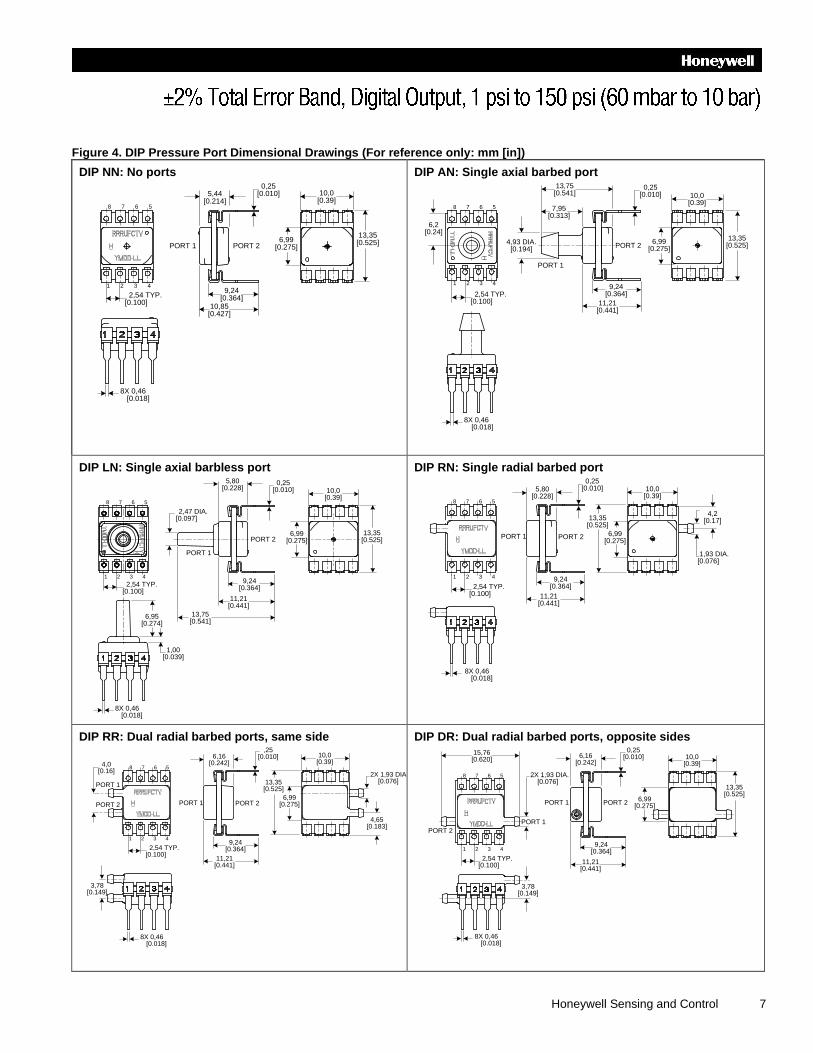
Figure 4. DIP Pressure Port Dimensional Drawings (For reference only: mm [in])
DIP NN: No ports
13,35[0.525]
10,0[0.39]
6,99[0.275]
1 2 3 4
8 7 6 5
10,85[0.427]
9,24[0.364]
5,44[0.214]
2,54 TYP.[0.100]
8X 0,46 [0.018]
0,25[0.010]
PORT 1 PORT 2
DIP AN: Single axial barbed port
1 2 3 4
10,0[0.39]
13,35[0.525]
PORT 1
8 7 6 5
6,2[0.24]
2,54 TYP.[0.100]
9,24[0.364]
11,21[0.441]
7,95[0.313]
13,75[0.541]
4,93 DIA.[0.194]
PORT 26,99
[0.275]
8X 0,46 [0.018]
0,25[0.010]
DIP LN: Single axial barbless port
PORT 1
PORT 2
10,0[0.39]
13,35[0.525]
6,99[0.275]
2,54 TYP.[0.100]
6,95[0.274]
1,00[0.039]
9,24[0.364]
11,21[0.441]
13,75[0.541]
5,80[0.228]
1 2 3 4
8 7 6 5
8X 0,46 [0.018]
0,25[0.010]
2,47 DIA.[0.097]
DIP RN: Single radial barbed port
PORT 1
13,35[0.525]
10,0[0.39]
6,99[0.275]
1 2 3 4
8 7 6 5
11,21[0.441]
9,24[0.364]
5,80[0.228]
2,54 TYP.[0.100]
8X 0,46 [0.018]
0,25[0.010]
1,93 DIA. [0.076]
4,2[0.17]
PORT 2
DIP RR: Dual radial barbed ports, same side
8X 0,46 [0.018]
13,35[0.525]
10,0[0.39]
6,99[0.275]
1 2 3 4
8 7 6 5
6,16[0.242]
2,54 TYP.[0.100]
11,21[0.441]
9,24[0.364]
2X 1,93 DIA. [0.076]
4,65[0.183]
,25[0.010]
PORT 1 PORT 2
PORT 1
PORT 2
4,0[0.16]
3,78[0.149]
DIP DR: Dual radial barbed ports, opposite sides
10,0[0.39]
13,35[0.525]
PORT 1
PORT 2
1 2 3 4
8 7 6 5
6,16[0.242]
9,24[0.364]
2,54 TYP.[0.100]
15,76[0.620]
11,21[0.441]
2X 1,93 DIA.[0.076]
6,99[0.275]
8X 0,46 [0.018]
0,25[0.010]
PORT 1 PORT 2
3,78[0.149]
8 www.honeywell.com/sensing
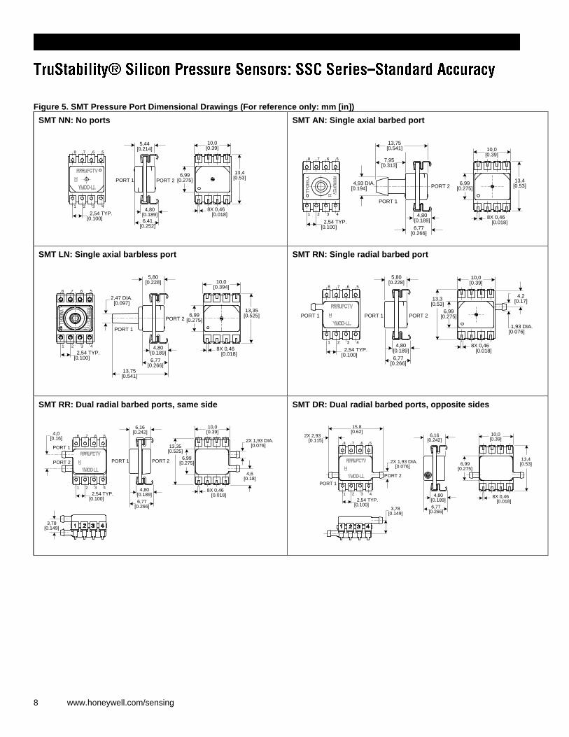
Figure 5. SMT Pressure Port Dimensional Drawings (For reference only: mm [in])
SMT NN: No ports
13,4[0.53]
10,0[0.39]
6,99[0.275]
1 2 3 4
8 7 6 5
5,44[0.214]
2,54 TYP.[0.100]
6,41[0.252]
4,80[0.189]
8X 0,46 [0.018]
PORT 1 PORT 2
SMT AN: Single axial barbed port
1 2 3 4
8 7 6 5
10,0[0.39]
13,4[0.53]
7,95[0.313]
13,75[0.541]
4,93 DIA.[0.194]
2,54 TYP.[0.100]
PORT 1
PORT 2
6,77[0.266]
4,80[0.189]
8X 0,46 [0.018]
6,99[0.275]
SMT LN: Single axial barbless port
10,0[0.394]
13,35[0.525]6,99
[0.275]
1 2 3 4
8 7 6 5
2,54 TYP.[0.100] 6,77
[0.266]
4,80[0.189]
5,80[0.228]
13,75[0.541]
8X 0,46 [0.018]
PORT 1
PORT 2
2,47 DIA.[0.097]
SMT RN: Single radial barbed port
13,3[0.53]
10,0[0.39]
6,99[0.275]
1 2 3 4
8 7 6 5
5,80[0.228]
2,54 TYP.[0.100]
6,77[0.266]
4,80[0.189]
8X 0,46 [0.018]
PORT 1
1,93 DIA. [0.076]
4,2[0.17]
PORT 1 PORT 2
SMT RR: Dual radial barbed ports, same side
10,0[0.39]
6,99[0.275]
1 2 3 4
8 7 6 5
6,16[0.242]
2,54 TYP.[0.100]
6,77[0.266]
4,80[0.189]
8X 0,46 [0.018]
13,35[0.525]
4,6[0.18]
PORT 1
PORT 2
2X 1,93 DIA. [0.076]
PORT 1 PORT 2
4,0[0.16]
3,78[0.149]
SMT DR: Dual radial barbed ports, opposite sides
1 2 3 4
8 7 6 5
13,4[0.53]
PORT 2
PORT 1
10,0[0.39]
6,99[0.275]
2X 2,93 [0.115]
15,8[0.62]
2,54 TYP.[0.100]
2X 1,93 DIA.[0.076]
6,77[0.266]
4,80[0.189]
6,16[0.242]
3,78[0.149]
8X 0,46 [0.018]

Honeywell Sensing and Control 9
Figure 6. SIP Package Dimensional Drawings (For reference only: mm [in])
SIP NN: No ports
2,54 TYP.[0.100]
10,0[0.39]
15,2[0.60]
10,0[0.39]
1 2 3 4
4X 0,51 [0.020]
4,87[0.192]
PORT 1 PORT 2
0,25[0.010]
SIP AA: Dual axial barbed ports, opposite sides
PORT 1 PORT 2
0,25[0.010]
1 2 3 4
10,0[0.39]
10,0[0.39]
2,54 TYP.[0.100]
15,2[0.60]
22,06[0.869]
2X 4.93 DIA.[0.194]
4X 0,51 [0.020]
SIP AN: Single axial barbed port
0,25[0.010] 2,54 TYP.
[0.100]
PORT 1
1 2 3 4
10,0[0.39]
4.93 DIA.[0.194]
10,0[0.39]
13,75[0.541]
15,2[0.60]
PORT 2
4X 0,51 [0.020]
SIP LN: Single barbless port
10,0[0.39]
15,2[0.60]
10,0[0.39]
1 2 3 4
2,54 TYP.[0.100]
PORT 1
PORT 2
0,25[0.010]
13,75[0.541]
4X 0,51 [0.020]
2,47 DIA.[0.097]
SIP FF: Fastener mount, dual axial barbed ports, opposite sides
0,25[0.010] 2,54 TYP.
[0.100]
29,48[1.161]
1 2 3 4
27,20[1.071]
23,12[0.910]
10,44[0.411]
PORT 1PORT 2
17,78[0.700]
20,16[0.794]
2X 4,78 DIA.[0.188]
2X 3.94 DIA.[0.155]
4X 0,51 [.020]
SIP FN: Fastener mount, single axial barbed port
1 2 3 4
17,78[0.700]
20,16[0.794]
2,54 TYP.[0.100]
0,25[0.010]
29,48[1.161]
23,12[0.910]
PORT 1PORT 2
16,38[0.645]
2X 3.94 DIA.[0.155]
4.78 DIA.[0.188]
4X 0,51 [0.020]
10 www.honeywell.com/sensing
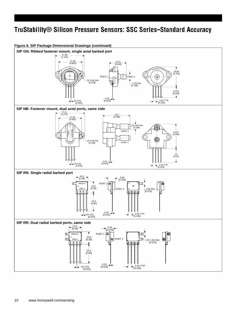
Figure 6. SIP Package Dimensional Drawings (continued)
SIP GN: Ribbed fastener mount, single axial barbed port
2,54 TYP.[0.100]
21,60[0.850]
PORT 1PORT 2
1 2 3 4
4.78 DIA.[0.188]
0,25[0.010]
2X 3,94 DIA.[0.155]
27,96[1.101]
16,51[0.650]
19,06[0.750]
10,63[0.418]
4X 0,51 [0.020]
SIP NB: Fastener mount, dual axial ports, same side
0,25[0.010]
2,54 TYP.[0.100]
22,87[0.900]
13[0.52]
2X 3.50 DIA.[0.138]
21,60[0.850]
27,31[1.075] 25,3
[0.996]
PORT 1
PORT 2
4 3 2 1
4X 0,51 [0.020]
2X 4,80 DIA.[0.189]
SIP RN: Single radial barbed port
0,25[0.010] 2,54 TYP.
[0.100]
PORT 1
PORT 2
10,0[0.39]
15,2[0.60]
10,0[0.39]
1 2 3 4
5,80[0.228]
1,92 DIA.[0.076]
4X 0,51 [0.020]
SIP RR: Dual radial barbed ports, same side
0,25[0.010] 2,54 TYP.
[0.100]
PORT 1
PORT 2
1 2 3 4
10,0[0.39]
15,2[0.60]
10,0[0.39] 2X 1,92 DIA.
[0.076]
6,16[0.243]
4X 0,51 [0.020]
Honeywell Sensing and Control 11
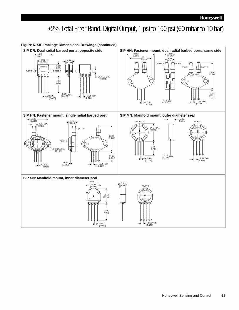
Figure 6. SIP Package Dimensional Drawings (continued)
SIP DR: Dual radial barbed ports, opposite side
0,25[0.010] 2,54 TYP.
[0.100]
PORT 1 PORT 2
1 2 3 4
10,0[0.39]
10,0[0.39]
15,2[0.60]
6,16[0.243]
2X 4.93 DIA.[0.194]
15,8[0.62]
4X 0,51 [0.020]
SIP HH: Fastener mount, dual radial barbed ports, same side
0,25[0.010]
1 2 3 4
28,96[1.140]
2,54 TYP.[0.100]
PORT 1PORT 2
29,62[1.166]
23,12[0.910]
11,27[0.444]
6,64[0.261]
10,58[0.416]
4X 0,51 [0.020]
PORT 1PORT 2
SIP HN: Fastener mount, single radial barbed port
28,96[1.140]
11,27[0.444]
23,12[0.910]
0,25[0.010] 2,54 TYP.
[0.100]
1 2 3 4
2X 3,94 DIA.[0.155]
7,97[0.314] 4,78 DIA.
[0.188]
4X 0,51 [0.020]
PORT 1
PORT 2
SIP MN: Manifold mount, outer diameter seal
2,54 TYP.[0.100]
0,25[0.010]
1 2 3 4
PORT 1PORT 2
15,24 DIA.[0.600]
12,5[0.49]
5,36[0.211]
4X 0,51 [0.020]
SIP SN: Manifold mount, inner diameter seal
2,54 TYP.[0.100]
1 2 3 4
13,11[0.516]
12,57[0.495]
15,6[0.61]
5,1[0.20]
4X 0,51 [0.020]
PORT 1
PORT 2
Sensing and Control
Honeywell
1985 Douglas Drive North
Golden Valley, MN 55422
www.honeywell.com
008213-2-EN IL50 GLO Printed in USA
March 2011
© 2011 Honeywell International Inc.
WARNING PERSONAL INJURY
DO NOT USE these products as safety or emergency stop
devices or in any other application where failure of the
product could result in personal injury.
Failure to comply with these instructions could result
in death or serious injury.
WARRANTY/REMEDY
Honeywell warrants goods of its manufacture as being free of
defective materials and faulty workmanship. Honeywell s
standard product warranty applies unless agreed to otherwise
by Honeywell in writing; please refer to your order
acknowledgement or consult your local sales office for specific
warranty details. If warranted goods are returned to Honeywell
during the period of coverage, Honeywell will repair or replace,
at its option, without charge those items it finds defective. The
foregoing is buyer s sole remedy and is in lieu of all other
warranties, expressed or implied, including those of
merchantability and fitness for a particular purpose. In no
event shall Honeywell be liable for consequential, special,
or indirect damages.
While we provide application assistance personally, through
our literature and the Honeywell web site, it is up to the
customer to determine the suitability of the product in the
application.
Specifications may change without notice. The information we
supply is believed to be accurate and reliable as of this
printing. However, we assume no responsibility for its use.
WARNING MISUSE OF DOCUMENTATION
The information presented in this product sheet is for
reference only. DO NOT USE this document as a
product installation guide.
Complete installation, operation, and maintenance
information is provided in the instructions supplied with
each product.
Failure to comply with these instructions could result in
death or serious injury.
SALES AND SERVICE
Honeywell serves its customers through a worldwide network
of sales offices, representatives and distributors. For
application assistance, current specifications, pricing or name
of the nearest Authorized Distributor, contact your local sales
office or:
E-mail: [email protected]
Internet: www.honeywell.com/sensing
Phone and Fax:
Asia Pacific +65 6355-2828; +65 6445-3033 Fax
Europe +44 (0) 1698 481481; +44 (0) 1698 481676 Fax
Latin America +1-305-805-8188; +1-305-883-8257 Fax
USA/Canada +1-800-537-6945; +1-815-235-6847
+1-815-235-6545 Fax