Embed Size (px)
Citation preview
ETSI TS 125 224 V15.0.0 (2018-07)
Universal Mobile Telecommunications System (UMTS); Physical layer procedures (TDD)
(3GPP TS 25.224 version 15.0.0 Release 15)
TECHNICAL SPECIFICATION
ETSI
ETSI TS 125 224 V15.0.0 (2018-07)13GPP TS 25.224 version 15.0.0 Release 15
Reference RTS/TSGR-0625224vf00
Keywords UMTS
ETSI
650 Route des Lucioles F-06921 Sophia Antipolis Cedex - FRANCE
Tel.: +33 4 92 94 42 00 Fax: +33 4 93 65 47 16
Siret N° 348 623 562 00017 - NAF 742 C
Association à but non lucratif enregistrée à la Sous-Préfecture de Grasse (06) N° 7803/88
Important notice
The present document can be downloaded from: http://www.etsi.org/standards-search
The present document may be made available in electronic versions and/or in print. The content of any electronic and/or print versions of the present document shall not be modified without the prior written authorization of ETSI. In case of any
existing or perceived difference in contents between such versions and/or in print, the only prevailing document is the print of the Portable Document Format (PDF) version kept on a specific network drive within ETSI Secretariat.
Users of the present document should be aware that the document may be subject to revision or change of status. Information on the current status of this and other ETSI documents is available at
https://portal.etsi.org/TB/ETSIDeliverableStatus.aspx
If you find errors in the present document, please send your comment to one of the following services: https://portal.etsi.org/People/CommiteeSupportStaff.aspx
Copyright Notification
No part may be reproduced or utilized in any form or by any means, electronic or mechanical, including photocopying and microfilm except as authorized by written permission of ETSI.
The content of the PDF version shall not be modified without the written authorization of ETSI. The copyright and the foregoing restriction extend to reproduction in all media.
© ETSI 2018.
All rights reserved.
DECTTM, PLUGTESTSTM, UMTSTM and the ETSI logo are trademarks of ETSI registered for the benefit of its Members. 3GPPTM and LTETM are trademarks of ETSI registered for the benefit of its Members and
of the 3GPP Organizational Partners. oneM2M logo is protected for the benefit of its Members.
GSM® and the GSM logo are trademarks registered and owned by the GSM Association.
ETSI
ETSI TS 125 224 V15.0.0 (2018-07)23GPP TS 25.224 version 15.0.0 Release 15
Intellectual Property Rights Essential patents
IPRs essential or potentially essential to normative deliverables may have been declared to ETSI. The information pertaining to these essential IPRs, if any, is publicly available for ETSI members and non-members, and can be found in ETSI SR 000 314: "Intellectual Property Rights (IPRs); Essential, or potentially Essential, IPRs notified to ETSI in respect of ETSI standards", which is available from the ETSI Secretariat. Latest updates are available on the ETSI Web server (https://ipr.etsi.org/).
Pursuant to the ETSI IPR Policy, no investigation, including IPR searches, has been carried out by ETSI. No guarantee can be given as to the existence of other IPRs not referenced in ETSI SR 000 314 (or the updates on the ETSI Web server) which are, or may be, or may become, essential to the present document.
Trademarks
The present document may include trademarks and/or tradenames which are asserted and/or registered by their owners. ETSI claims no ownership of these except for any which are indicated as being the property of ETSI, and conveys no right to use or reproduce any trademark and/or tradename. Mention of those trademarks in the present document does not constitute an endorsement by ETSI of products, services or organizations associated with those trademarks.
Foreword This Technical Specification (TS) has been produced by ETSI 3rd Generation Partnership Project (3GPP).
The present document may refer to technical specifications or reports using their 3GPP identities, UMTS identities or GSM identities. These should be interpreted as being references to the corresponding ETSI deliverables.
The cross reference between GSM, UMTS, 3GPP and ETSI identities can be found under http://webapp.etsi.org/key/queryform.asp.
Modal verbs terminology In the present document "shall", "shall not", "should", "should not", "may", "need not", "will", "will not", "can" and "cannot" are to be interpreted as described in clause 3.2 of the ETSI Drafting Rules (Verbal forms for the expression of provisions).
"must" and "must not" are NOT allowed in ETSI deliverables except when used in direct citation.
ETSI
ETSI TS 125 224 V15.0.0 (2018-07)33GPP TS 25.224 version 15.0.0 Release 15
Contents Intellectual Property Rights ................................................................................................................................ 2
Foreword ............................................................................................................................................................. 2
Modal verbs terminology .................................................................................................................................... 2
Foreword ............................................................................................................................................................. 8
1 Scope ........................................................................................................................................................ 9
2 References ................................................................................................................................................ 9
3 Abbreviations ......................................................................................................................................... 10
4 Physical layer procedures for the 3.84 Mcps option .............................................................................. 11
4.1 General ............................................................................................................................................................. 11
4.2 Transmitter power control ................................................................................................................................ 11
4.2.1 General parameters ..................................................................................................................................... 11
4.2.2 Uplink control ............................................................................................................................................. 11
4.2.2.1 General limits ........................................................................................................................................ 11
4.2.2.2 PRACH ................................................................................................................................................. 12
4.2.2.3 DPCH, PUSCH and HS-SICH .............................................................................................................. 12
4.2.2.3.1 Gain factors ..................................................................................................................................... 12
4.2.2.3.2 Out of synchronisation handling ...................................................................................................... 13
4.2.2.4 E-PUCH ................................................................................................................................................ 13
4.2.2.4.1 Gain factors for E-PUCH ................................................................................................................ 14
4.2.2.5 E-RUCCH ............................................................................................................................................. 15
4.2.3 Downlink control ........................................................................................................................................ 15
4.2.3.1 P-CCPCH .............................................................................................................................................. 15
4.2.3.2 S-CCPCH, PICH ................................................................................................................................... 15
4.2.3.2A MICH .................................................................................................................................................... 15
4.2.3.3 SCH ....................................................................................................................................................... 16
4.2.3.3A PNBSCH ............................................................................................................................................... 16
4.2.3.4 DPCH, PDSCH ..................................................................................................................................... 16
4.2.3.4.1 Out of synchronisation handling ...................................................................................................... 17
4.2.3.5 HS-PDSCH ........................................................................................................................................... 17
4.2.3.6 HS-SCCH .............................................................................................................................................. 17
4.2.3.7 E-AGCH ............................................................................................................................................... 17
4.2.3.8 E-HICH ................................................................................................................................................. 17
4.3 Timing advance ................................................................................................................................................ 17
4.4 Synchronisation procedures.............................................................................................................................. 18
4.4.1 Cell search .................................................................................................................................................. 18
4.4.2 Dedicated channel synchronisation ............................................................................................................. 18
4.4.2.1 Synchronisation primitives .................................................................................................................... 18
4.4.2.1.1 General ............................................................................................................................................ 18
4.4.2.1.2 Downlink synchronisation primitives .............................................................................................. 18
4.4.2.1.2A Downlink synchronisation primitives for HS-channels ................................................................... 19
4.4.2.1.3 Uplink synchronisation primitives ................................................................................................... 19
4.4.2.2 Radio link monitoring ........................................................................................................................... 19
4.4.2.2.1 Downlink radio link failure ............................................................................................................. 19
4.4.2.2.2 Uplink radio link failure/restore ...................................................................................................... 20
4.5 Discontinuous transmission (DTX) procedure ................................................................................................. 20
4.5.1 Description of special bursts ....................................................................................................................... 20
4.5.2 Use of special bursts during DTX ............................................................................................................... 20
4.5.3 Use of special bursts for initial establishment / reconfiguration ................................................................. 21
4.5.4 Use of special bursts for DTX on beacon channels .................................................................................... 21
4.6 Downlink transmit diversity ............................................................................................................................. 21
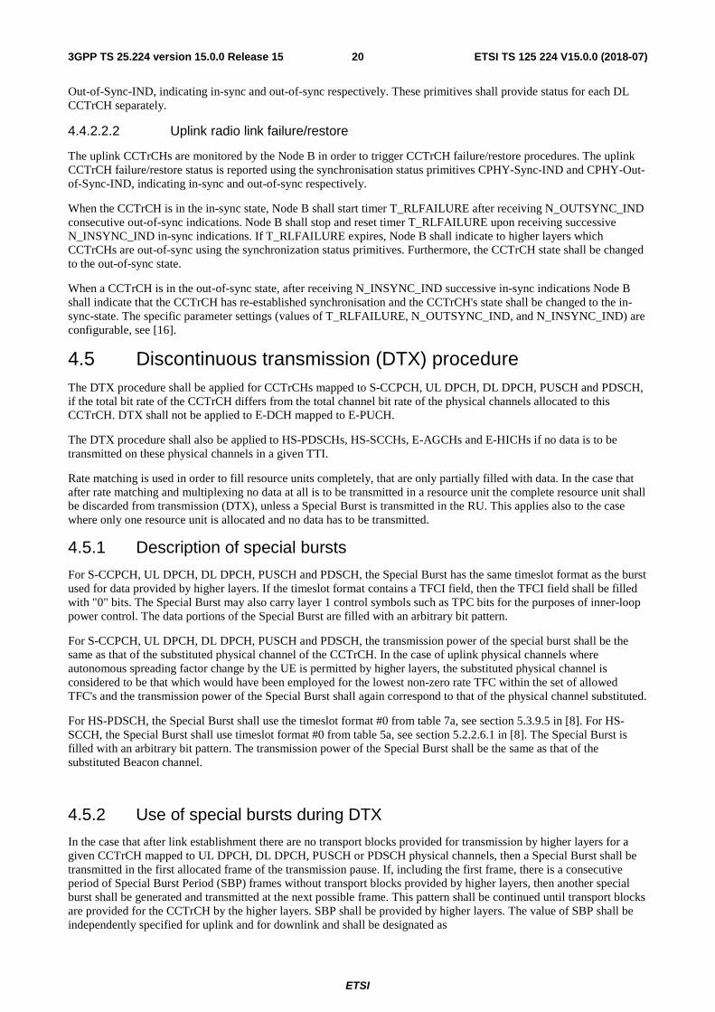
4.6.1 Transmit diversity for PDSCH, DPCH, HS-SCCH, HS-PDSCH and E-AGCH ........................................ 21
4.6.2 Transmit diversity for SCH and S-CCPCH ................................................................................................ 22
4.6.2.1 SCH transmission scheme ..................................................................................................................... 22
4.6.2.2 S-CCPCH transmission scheme ............................................................................................................ 22
ETSI
ETSI TS 125 224 V15.0.0 (2018-07)43GPP TS 25.224 version 15.0.0 Release 15
4.6.3 Transmit diversity for beacon channels ...................................................................................................... 23
4.6.3.1 SCTD transmission scheme .................................................................................................................. 23
4.7 Random access procedure ................................................................................................................................ 23
4.7.1 Physical random access procedure .............................................................................................................. 24
4.7A E-RUCCH transmission procedure .................................................................................................................. 24
4.8 DSCH procedure .............................................................................................................................................. 25
4.8.1 DSCH procedure with TFCI indication ...................................................................................................... 25
4.8.2 DSCH procedure with midamble indication ............................................................................................... 25
4.9 Node B synchronisation procedure over the air ............................................................................................... 25
4.9.1 Frequency acquisition phase ....................................................................................................................... 25
4.9.2 Initial synchronisation................................................................................................................................. 26
4.9.3 Steady-state phase ....................................................................................................................................... 26
4.9.4 Late entrant cells ......................................................................................................................................... 26
4.10 Idle periods for IPDL location method ............................................................................................................. 26
4.10.1 General ........................................................................................................................................................ 26
4.10.2 Parameters of IPDL .................................................................................................................................... 26
4.10.3 Calculation of idle period position .............................................................................................................. 27
4.11 HS-DSCH procedure ........................................................................................................................................ 28
4.11.1 Link adaptation procedure .......................................................................................................................... 28
4.11.2 HS-DSCH channel quality indication procedure ........................................................................................ 29
4.12 Macro-diversity procedure ............................................................................................................................... 30
4.13 E-DCH related procedures ............................................................................................................................... 30
4.13.1 ACK/NACK detection ................................................................................................................................ 30
4.13.2 Serving and neighbour cell pathloss metric derivation ............................................................................... 30
4.13.3 Channelisation code hopping procedure for E-PUCH ................................................................................ 31
4.14 Physical layer procedures for 3.84 Mcps MBSFN IMB ................................................................................... 33
4.14.1 Radio frame timing on the MBSFN layer ................................................................................................... 33
4.14.2 Downlink power control ............................................................................................................................. 33
4.14.2.1 S-CCPCH .............................................................................................................................................. 33
4.14.2.2 MICH .................................................................................................................................................... 33
4.14.2.3 P-CPICH ............................................................................................................................................... 33
4.14.2.4 T-CPICH ............................................................................................................................................... 34
5 Physical layer procedures for the 1.28 Mcps option .............................................................................. 34
5.1 Transmitter power control ................................................................................................................................ 34
5.1.1 Uplink control ............................................................................................................................................. 34
5.1.1.1 General limits ........................................................................................................................................ 34
5.1.1.2 UpPCH .................................................................................................................................................. 34
5.1.1.3 PRACH ................................................................................................................................................. 34
5.1.1.4 DPCH and PUSCH ............................................................................................................................... 34
5.1.1.4.1 Gain factors ..................................................................................................................................... 35
5.1.1.4.2 Out of synchronization handling ..................................................................................................... 35
5.1.1.5 HS-SICH ............................................................................................................................................... 35
5.1.1.6 E-PUCH ................................................................................................................................................ 36
5.1.1.6.1 Gain factors for E-PUCH ................................................................................................................ 37
5.1.1.7 E-RUCCH ............................................................................................................................................. 38
5.1.1.8 Standalone midamble channel ............................................................................................................... 38
5.1.2 Downlink control ........................................................................................................................................ 39
5.1.2.1 P-CCPCH .............................................................................................................................................. 39
5.1.2.2 The power of the FPACH ..................................................................................................................... 39
5.1.2.3 S-CCPCH, PICH ................................................................................................................................... 39
5.1.2.3A MICH .................................................................................................................................................... 39
5.1.2.4 DPCH, PDSCH ..................................................................................................................................... 39
5.1.2.4.1 Out of synchronisation handling ...................................................................................................... 40
5.1.2.5 HS-PDSCH ........................................................................................................................................... 40
5.1.2.6 HS-SCCH .............................................................................................................................................. 40
5.1.2.7 PLCCH .................................................................................................................................................. 40
5.1.2.8 E-AGCH ............................................................................................................................................... 40
5.1.2.9 E-HICH ................................................................................................................................................. 41
5.2 UL synchronisation .......................................................................................................................................... 41
5.2.1 General description ..................................................................................................................................... 41
5.2.1.1 Preparation of uplink synchronization (downlink synchronization) ..................................................... 41
ETSI
ETSI TS 125 224 V15.0.0 (2018-07)53GPP TS 25.224 version 15.0.0 Release 15
5.2.1.2 Establishment of uplink synchronization .............................................................................................. 41
5.2.1.3 Maintenance of uplink synchronisation ................................................................................................ 41
5.2.2 UpPCH ........................................................................................................................................................ 41
5.2.3 PRACH ....................................................................................................................................................... 42
5.2.4 DPCH and PUSCH ..................................................................................................................................... 42
5.2.4.1 Out of synchronization handling ........................................................................................................... 42
5.2.5 HS-SICH ..................................................................................................................................................... 42
5.2.6 E-PUCH ...................................................................................................................................................... 43
5.2.7 E-RUCCH ................................................................................................................................................... 43
5.2.8 Standalone midamble channel .................................................................................................................... 43
5.3 Synchronisation procedures.............................................................................................................................. 43
5.3.1 Cell search .................................................................................................................................................. 43
5.3.2 DCH synchronization ................................................................................................................................. 43
5.3.2A Shared physical channel synchronization ................................................................................................... 43
5.3.2A.1 Synchronisation primitives .................................................................................................................... 44
5.3.2A.1.1 General ............................................................................................................................................ 44
5.3.2A.1.2 Downlink synchronisation primitives .............................................................................................. 44
5.3.2A.1.3 Uplink synchronisation primitives ................................................................................................... 44
5.3.2A.2 Radio link monitoring ........................................................................................................................... 44
5.3.2A.2.1 Downlink radio link failure ............................................................................................................. 44
5.3.2A.2.2 Uplink radio link failure/restore ...................................................................................................... 44
5.3.3 Synchronization procedure in CELL_FACH state ..................................................................................... 45
5.3.3.1 Uplink synchronization status detection ................................................................................................ 45
5.3.3.2 Establishment of uplink synchronization .............................................................................................. 45
5.4 Discontinuous transmission (DTX) procedure ................................................................................................. 45
5.4.1 Description of special bursts ....................................................................................................................... 45
5.4.2 Use of special bursts during DTX ............................................................................................................... 46
5.4.3 Use of special bursts for initial establishment / reconfiguration ................................................................. 46
5.5 Downlink transmit diversity ............................................................................................................................. 46
5.5.1 Transmit diversity for PDSCH, DPCH, HS-SCCH, HS-PDSCH and E-AGCH ........................................ 46
5.5.1.1 TSTD for PDSCH and DPCH ............................................................................................................... 46
5.5.1.2 Closed loop Tx diversity for PDSCH, DPCH, HS-SCCH, HS-PDSCH and E-AGCH ........................ 47
5.5.2 Transmit diversity for DwPCH ................................................................................................................... 48
5.5.3 Transmit diversity for P-CCPCH ................................................................................................................ 48
5.5.3.1 TSTD transmission scheme for P-CCPCH ........................................................................................... 48
5.5.4 SCTD transmission scheme for beacon channels ....................................................................................... 48
5.6 Random access procedure ................................................................................................................................ 49
5.6.1 Definitions .................................................................................................................................................. 49
5.6.1A UpPCH sub-channel ................................................................................................................................... 50
5.6.2 Preparation of random access ..................................................................................................................... 50
5.6.3 Random access procedure ........................................................................................................................... 51
5.6.3.1 The use and generation of the information fields transmitted in the FPACH ....................................... 52
5.6.3.1.1 Signature reference number ............................................................................................................. 52
5.6.3.1.2 Relative sub-frame number ............................................................................................................. 52
5.6.3.1.3 Received starting position of the UpPCH (UpPCHPOS) ................................................................... 53
5.6.3.1.4 Transmit power level command for the RACH message ................................................................ 53
5.6.3A E-RUCCH procedure .................................................................................................................................. 53
5.6.4 Random access collision ............................................................................................................................. 54
5.7 Node B synchronisation procedure over the air ............................................................................................... 54
5.7.1 Initial synchronisation................................................................................................................................. 54
5.7.2 Steady-state phase ....................................................................................................................................... 54
5.7.3 Late entrant cells ......................................................................................................................................... 54
5.8 Idle periods for IPDL location method ............................................................................................................. 55
5.8.1 General ........................................................................................................................................................ 55
5.8.2 Parameters of IPDL .................................................................................................................................... 55
5.8.3 Calculation of idle period position .............................................................................................................. 55
5.9 HS-DSCH procedure in CELL_DCH state ...................................................................................................... 56
5.9.1 Link adaptation procedure .......................................................................................................................... 56
5.9.2 HS-DSCH channel quality indication procedure ........................................................................................ 57
5.9.3 HS-SCCH monitoring procedure ................................................................................................................ 58
5.9A HS-DSCH procedure in CELL_FACH state .................................................................................................... 58
5.9A.1 Link adaptation procedure .......................................................................................................................... 58
ETSI
ETSI TS 125 224 V15.0.0 (2018-07)63GPP TS 25.224 version 15.0.0 Release 15
5.9A.2 HS-DSCH channel quality indication procedure ........................................................................................ 59
5.9A.3 HS-SCCH monitoring procedure ................................................................................................................ 59
5.9B HS-DSCH procedure in CELL_PCH or URA_PCH state ................................................................................ 59
5.9B.1 Link adaptation procedure .......................................................................................................................... 59
5.9B.2 HS-DSCH channel quality indication procedure ........................................................................................ 60
5.9B.3 HS-SCCH monitoring procedure ................................................................................................................ 60
5.10 Macro-diversity procedure ............................................................................................................................... 60
5.11 E-DCH Procedure............................................................................................................................................. 60
5.11.1 ACK/NACK detection ................................................................................................................................ 60
5.11.2 Serving and neighbour cell pathloss metric derivation ............................................................................... 60
5.11.3 E-AGCH monitoring in CELL_DCH state ................................................................................................. 62
5.11.3A E-AGCH monitoring in CELL_FACH state ............................................................................................... 62
5.12 MIMO operation of HS-DSCH ........................................................................................................................ 62
5.12.1 General procedure ....................................................................................................................................... 62
5.12.2 Identification of MIMO dual stream ........................................................................................................... 63
5.12.3 UE antennas time switched transmission .................................................................................................... 63
5.12A MU-MIMO operation of HS-DSCH and E-DCH ............................................................................................. 64
5.13 Control channel discontinuous reception procedures ....................................................................................... 64
5.13.1 Discontinuous downlink reception ............................................................................................................. 65
5.13.2 HS-SCCH orders ........................................................................................................................................ 66
6 Physical layer procedures for the 7.68 Mcps option .............................................................................. 66
6.1 Transmitter power control ................................................................................................................................ 66
6.2 Timing advance ................................................................................................................................................ 66
6.3 Synchronisation procedures.............................................................................................................................. 67
6.4 Discontinuous transmission (DTX) procedure ................................................................................................. 67
6.5 Downlink transmit diversity ............................................................................................................................. 67
6.5.1 Transmit diversity for PDSCH, DPCH, HS-SCCH, HS-PDSCH and E-AGCH ........................................ 67
6.5.2 Transmit diversity for SCH and S-CCPCH ................................................................................................ 67
6.5.3 Transmit diversity for Beacon Channels ..................................................................................................... 67
6.5.3.1 SCTD transmission scheme .................................................................................................................. 67
6.6 Random access procedure ................................................................................................................................ 68
6.6.1 Physical random access procedure .............................................................................................................. 68
6.6A E-RUCCH transmission procedure .................................................................................................................. 68
6.7 DSCH procedure .............................................................................................................................................. 68
6.8 Idle periods for IPDL location method ............................................................................................................. 68
6.9 HS-DSCH procedure ........................................................................................................................................ 68
6.9.1 Link adaptation procedure .......................................................................................................................... 68
6.9.2 HS-DSCH channel quality indication procedure ........................................................................................ 69
6.10 Macro-diversity procedure ............................................................................................................................... 69
6.11 E-DCH related procedures ............................................................................................................................... 69
6.11.1 ACK/NACK detection ................................................................................................................................ 69
6.11.2 Serving and neighbour cell pathloss metric derivation ............................................................................... 69
6.11.3 Channelisation code hopping procedure for E-PUCH ................................................................................ 69
Annex A (informative): Power Control ................................................................................................ 72
A.1 Example implementation of downlink power control in the UE ............................................................ 72
A.2 Example implementation of closed loop uplink power control in Node B for 1.28Mcps TDD ............. 72
A.3 Example implementation of downlink power control in UE for 1.28Mcps TDD when TSTD is used......................................................................................................................................................... 72
A.4 Example implementation of open loop power control for access procedure for 1.28Mcps TDD .......... 73
A.5 Example implementation of closed loop uplink HS-SICH power control in Node B for 1.28Mcps TDD ........................................................................................................................................................ 73
Annex B (informative): Determination of weight information........................................................... 74
B.1 STD weights ........................................................................................................................................... 74
B.2 TxAA weights ........................................................................................................................................ 74
ETSI
ETSI TS 125 224 V15.0.0 (2018-07)73GPP TS 25.224 version 15.0.0 Release 15
Annex C (informative): Cell search procedure for 3.84Mcps TDD ................................................... 75
Annex CA (informative): Cell search procedure for 1.28Mcps TDD ................................................... 76
Annex CB (informative): Examples random access procedure for 1.28Mcps TDD ............................ 78
Annex D (informative): Change history ............................................................................................... 80
History .............................................................................................................................................................. 85
ETSI
ETSI TS 125 224 V15.0.0 (2018-07)83GPP TS 25.224 version 15.0.0 Release 15
Foreword This Technical Specification (TS) has been produced by the 3rd Generation Partnership Project (3GPP).
The contents of the present document are subject to continuing work within the TSG and may change following formal TSG approval. Should the TSG modify the contents of the present document, it will be re-released by the TSG with an identifying change of release date and an increase in version number as follows:
Version x.y.z
where:
x the first digit:
1 presented to TSG for information;
2 presented to TSG for approval;
3 or greater indicates TSG approved document under change control.
y the second digit is incremented for all changes of substance, i.e. technical enhancements, corrections, updates, etc.
z the third digit is incremented when editorial only changes have been incorporated in the document.
ETSI
ETSI TS 125 224 V15.0.0 (2018-07)93GPP TS 25.224 version 15.0.0 Release 15
1 Scope The present document describes the Physical Layer Procedures in the TDD mode of UTRA.
2 References The following documents contain provisions which, through reference in this text, constitute provisions of the present document.
- References are either specific (identified by date of publication, edition number, version number, etc.) or non-specific.
- For a specific reference, subsequent revisions do not apply.
- For a non-specific reference, the latest version applies. In the case of a reference to a 3GPP document (including a GSM document), a non-specific reference implicitly refers to the latest version of that document in the same Release as the present document.
[1] 3GPP TS 25.201: "Physical layer - general description".
[2] 3GPP TS 25.102: "UE physical layer capabilities".
[3] 3GPP TS 25.211: "Physical channels and mapping of transport channels onto physical channels (FDD)".
[4] 3GPP TS 25.212: "Multiplexing and channel coding (FDD)".
[5] 3GPP TS 25.213: "Spreading and modulation (FDD)".
[6] 3GPP TS 25.214: "Physical layer procedures (FDD)".
[7] 3GPP TS 25.215: "Physical Layer - Measurements (FDD)".
[8] 3GPP TS 25.221: "Physical channels and mapping of transport channels onto physical channels (TDD)".
[9] 3GPP TS 25.222: "Multiplexing and channel coding (TDD)".
[10] 3GPP TS 25.223: "Spreading and modulation (TDD)".
[11] 3GPP TS 25.225: "Physical Layer - Measurements (TDD)".
[12] 3GPP TS 25.301: "Radio Interface Protocol Architecture".
[13] 3GPP TS 25.302: "Services Provided by the Physical Layer".
[14] 3GPP TS 25.401: "UTRAN Overall Description".
[15] 3GPP TS 25.331: "RRC Protocol Specification"
[16] 3GPP TS 25.433: "UTRAN Iub Interface NBAP Signalling"
[17] 3GPP TS 25.105: "UTRA (BS) TDD; Radio transmission and Reception"
[18] 3GPP TS 25.321: "MAC protocol specification"
[19] 3GPP TS 25.303: "Interlayer Procedures in Connected Mode"
[20] 3GPP TS 25.402: "Synchronisation in UTRAN Stage 2"
ETSI
ETSI TS 125 224 V15.0.0 (2018-07)103GPP TS 25.224 version 15.0.0 Release 15
3 Abbreviations For the purposes of the present document, the following abbreviations apply:
ACK Acknowledgement ASC Access Service Class BCCH Broadcast Control Channel BCH Broadcast Channel CCTrCH Coded Composite Transport Channel CDMA Code Division Multiple Access CQI Channel Quality Information CRC Cyclic Redundancy Check DCA Dynamic Channel Allocation DL Downlink DPCH Dedicated Physical Channel DTX Discontinuous Transmission E-AGCH E-DCH Absolute Grant Channel ECSN E-AGCH Cyclic Sequence Number E-DCH Enhanced Dedicated Channel E-HICH E-DCH Hybrid ARQ Indicator Channel ENI E-UCCH Number Indicator E-PUCH E-DCH Physical Uplink Channel E-RUCCH E-DCH Random Access Uplink Control Channel E-UCCH E-DCH Uplink Control Channel FACH Forward Access Channel FDD Frequency Division Duplex HS-DSCH High Speed Downlink Shared Channel HS-PDSCH High Speed Physical Downlink Shared Channel HS-SCCH Shared Control Channel for HS-DSCH HS-SICH Shared Information Channel for HS-DSCH IMB Integrated Mobile Broadcast ISCP Interference Signal Code Power MAC Medium Access Control MBMS Multimedia Broadcast/Multicast Service MBSFN MBMS over a Single Frequency Network MICH MBMS Indicator Channel MIMO single user Multiple Input Multiple Output MS burst MBSFN Special burst MT burst MBSFN Traffic burst MU-MIMO Multi-user Multiple Input Multiple Output NACK Negative Acknowledgement NRT Non-Real Time P-CCPCH Primary Common Control Physical Channel PC Power Control PDSCH Physical Downlink Shared Channel PICH Paging Indicator Channel PLCCH Physical Layer Common Control Channel PRACH Physical Random Access Channel PUSCH Physical Uplink Shared Channel RACH Random Access Channel RL Radio Link RRC Radio Resource Control RSCP Received Signal Code Power RT Real Time RU Resource Unit SBGP Special Burst Generation Gap SBP Special Burst Period SBSP Special Burst Scheduling Period S-CCPCH Secondary Common Control Physical Channel SCH Synchronisation Channel SCTD Space Code Transmit Diversity
ETSI
ETSI TS 125 224 V15.0.0 (2018-07)113GPP TS 25.224 version 15.0.0 Release 15
SFN System Frame Number SIR Signal–to-Interference Ratio SNPL Serving and Neighbour cell Pathloss SSCH Secondary Synchronisation Channel STD Selective Transmit Diversity TA Timing Advance TDD Time Division Duplex TF Transport Format TFC Transport Format Combination TFCI Transport Format Combination Indicator TFCS Transport Format Combination Set TFRI Transport Format Resource Indicator TPC Transmit Power Control TSTD Time Switched Transmit Diversity TTI Transmission Time Interval TxAA Transmit Adaptive Antennas UE User Equipment UL Uplink UMTS Universal Mobile Telecommunications System UTRAN UMTS Radio Access Network VBR Variable Bit Rate
4 Physical layer procedures for the 3.84 Mcps option
4.1 General Sub-clauses 4.2 to 4.13 do not apply to 3.84 Mcps MBSFN IMB operation. Physical layer procedures for 3.84 Mcps MBSFN IMB operation are described in sub-clause 4.14.
4.2 Transmitter power control
4.2.1 General parameters
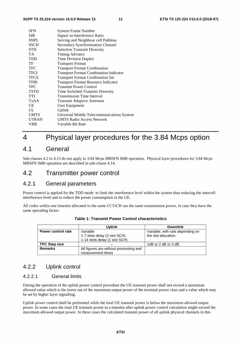
Power control is applied for the TDD mode to limit the interference level within the system thus reducing the intercell interference level and to reduce the power consumption in the UE.
All codes within one timeslot allocated to the same CCTrCH use the same transmission power, in case they have the same spreading factor.
Table 1: Transmit Power Control characteristics
Uplink Downlink Power control rate Variable
1-7 slots delay (2 slot SCH) 1-14 slots delay (1 slot SCH)
Variable, with rate depending on the slot allocation.
TPC Step size -- 1dB or 2 dB or 3 dB Remarks All figures are without processing and
measurement times
4.2.2 Uplink control
4.2.2.1 General limits
During the operation of the uplink power control procedure the UE transmit power shall not exceed a maximum allowed value which is the lower out of the maximum output power of the terminal power class and a value which may be set by higher layer signalling.
Uplink power control shall be performed while the total UE transmit power is below the maximum allowed output power. In some cases the total UE transmit power in a timeslot after uplink power control calculation might exceed the maximum allowed output power. In these cases the calculated transmit power of all uplink physical channels in this
ETSI
ETSI TS 125 224 V15.0.0 (2018-07)123GPP TS 25.224 version 15.0.0 Release 15
timeslot shall be scaled by the same amount in dB before transmission. The total UE transmission power used shall be the maximum allowed output power.
The UTRAN may not expect the UE to be capable of reducing its total transmit power below the minimum level specified in [2].
4.2.2.2 PRACH
The transmit power for the PRACH is set by higher layers based on open loop power control as described in [15].
4.2.2.3 DPCH, PUSCH and HS-SICH
The transmit power for DPCH, PUSCH and HS-SICH is set by higher layers based on open loop power control as described in [15].
In the case that an ACK is being transmitted on the HS-SICH, the UE shall apply a power offset to the transmit power of the entire HS-SICH. This power offset shall be signalled by higher layers.
4.2.2.3.1 Gain factors
Two or more transport channels may be multiplexed onto a CCTrCH as described in [9]. These transport channels undergo rate matching which involves repetition or puncturing. This rate matching affects the transmit power required to obtain a particular Eb/N0. Thus, the transmission power of the CCTrCH shall be weighted by a gain factor β.
There are two ways of controlling the gain factors for different TFC's within a CCTrCH transmitted in a radio frame:
- β is signalled for the TFC, or
- β is computed for the TFC, based upon the signalled settings for a reference TFC.
Combinations of the two above methods may be used to associate β values to all TFC's in the TFCS for a CCTrCH. The two methods are described in sections 4.2.2.3.1.1 and 4.2.2.3.1.2 respectively. Several reference TFC's for several different CCTrCH's may be signalled from higher layers.
The weight and gain factors may vary on a radio frame basis depending upon the current SF and TFC used. The setting of weight and gain factors is independent of any other form of power control. That means that the transmit power PUL is calculated according to the formula given in [15] and then the weight and gain factors are applied on top of that, cf. [10].
4.2.2.3.1.1 Signalled gain factors
When the gain factor βj is signalled by higher layers for a certain TFC, the signalled values are used directly for weighting DPCH or PUSCH within a CCTrCH. Exact values are given in [10].
4.2.2.3.1.2 Computed gain factors
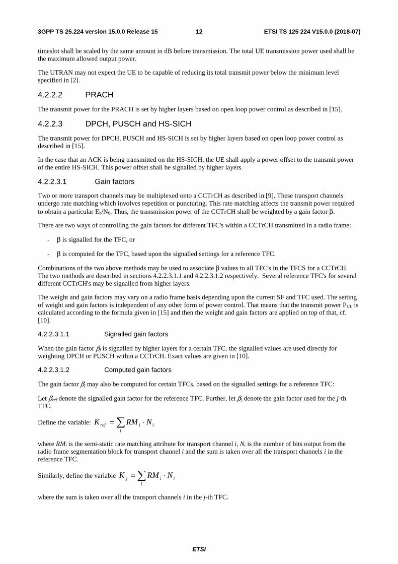
The gain factor βj may also be computed for certain TFCs, based on the signalled settings for a reference TFC:
Let βref denote the signalled gain factor for the reference TFC. Further, let βj denote the gain factor used for the j-th TFC.
Define the variable:
where RMi is the semi-static rate matching attribute for transport channel i, Ni is the number of bits output from the radio frame segmentation block for transport channel i and the sum is taken over all the transport channels i in the reference TFC.
Similarly, define the variable
where the sum is taken over all the transport channels i in the j-th TFC.
⋅=i
iiref NRMK
⋅=i
iij NRMK
ETSI
ETSI TS 125 224 V15.0.0 (2018-07)133GPP TS 25.224 version 15.0.0 Release 15
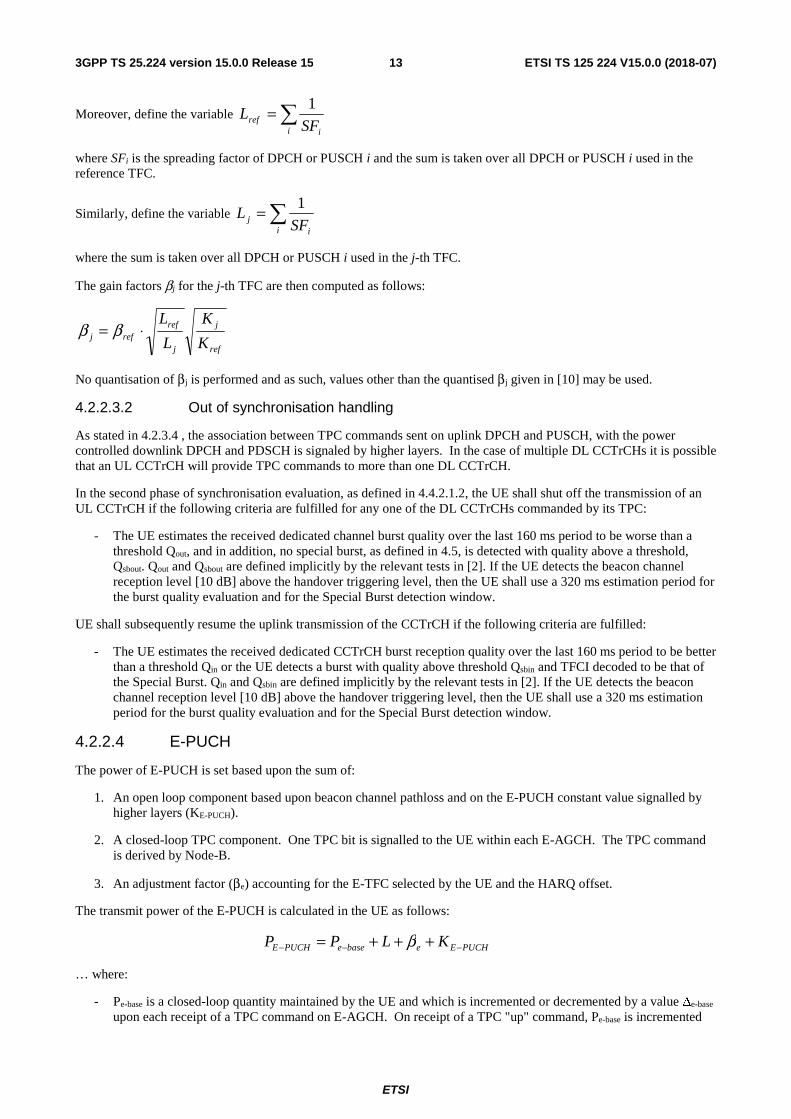
Moreover, define the variable
where SFi is the spreading factor of DPCH or PUSCH i and the sum is taken over all DPCH or PUSCH i used in the reference TFC.
Similarly, define the variable
where the sum is taken over all DPCH or PUSCH i used in the j-th TFC.
The gain factors βj for the j-th TFC are then computed as follows:
ref
j
j
refrefj K
K
L
L⋅= ββ
No quantisation of βj is performed and as such, values other than the quantised βj given in [10] may be used.
4.2.2.3.2 Out of synchronisation handling
As stated in 4.2.3.4 , the association between TPC commands sent on uplink DPCH and PUSCH, with the power controlled downlink DPCH and PDSCH is signaled by higher layers. In the case of multiple DL CCTrCHs it is possible that an UL CCTrCH will provide TPC commands to more than one DL CCTrCH.
In the second phase of synchronisation evaluation, as defined in 4.4.2.1.2, the UE shall shut off the transmission of an UL CCTrCH if the following criteria are fulfilled for any one of the DL CCTrCHs commanded by its TPC:
- The UE estimates the received dedicated channel burst quality over the last 160 ms period to be worse than a threshold Qout, and in addition, no special burst, as defined in 4.5, is detected with quality above a threshold, Qsbout. Qout and Qsbout are defined implicitly by the relevant tests in [2]. If the UE detects the beacon channel reception level [10 dB] above the handover triggering level, then the UE shall use a 320 ms estimation period for the burst quality evaluation and for the Special Burst detection window.
UE shall subsequently resume the uplink transmission of the CCTrCH if the following criteria are fulfilled:
- The UE estimates the received dedicated CCTrCH burst reception quality over the last 160 ms period to be better than a threshold Qin or the UE detects a burst with quality above threshold Qsbin and TFCI decoded to be that of the Special Burst. Qin and Qsbin are defined implicitly by the relevant tests in [2]. If the UE detects the beacon channel reception level [10 dB] above the handover triggering level, then the UE shall use a 320 ms estimation period for the burst quality evaluation and for the Special Burst detection window.
4.2.2.4 E-PUCH
The power of E-PUCH is set based upon the sum of:
1. An open loop component based upon beacon channel pathloss and on the E-PUCH constant value signalled by higher layers (KE-PUCH).
2. A closed-loop TPC component. One TPC bit is signalled to the UE within each E-AGCH. The TPC command is derived by Node-B.
3. An adjustment factor (βe) accounting for the E-TFC selected by the UE and the HARQ offset.
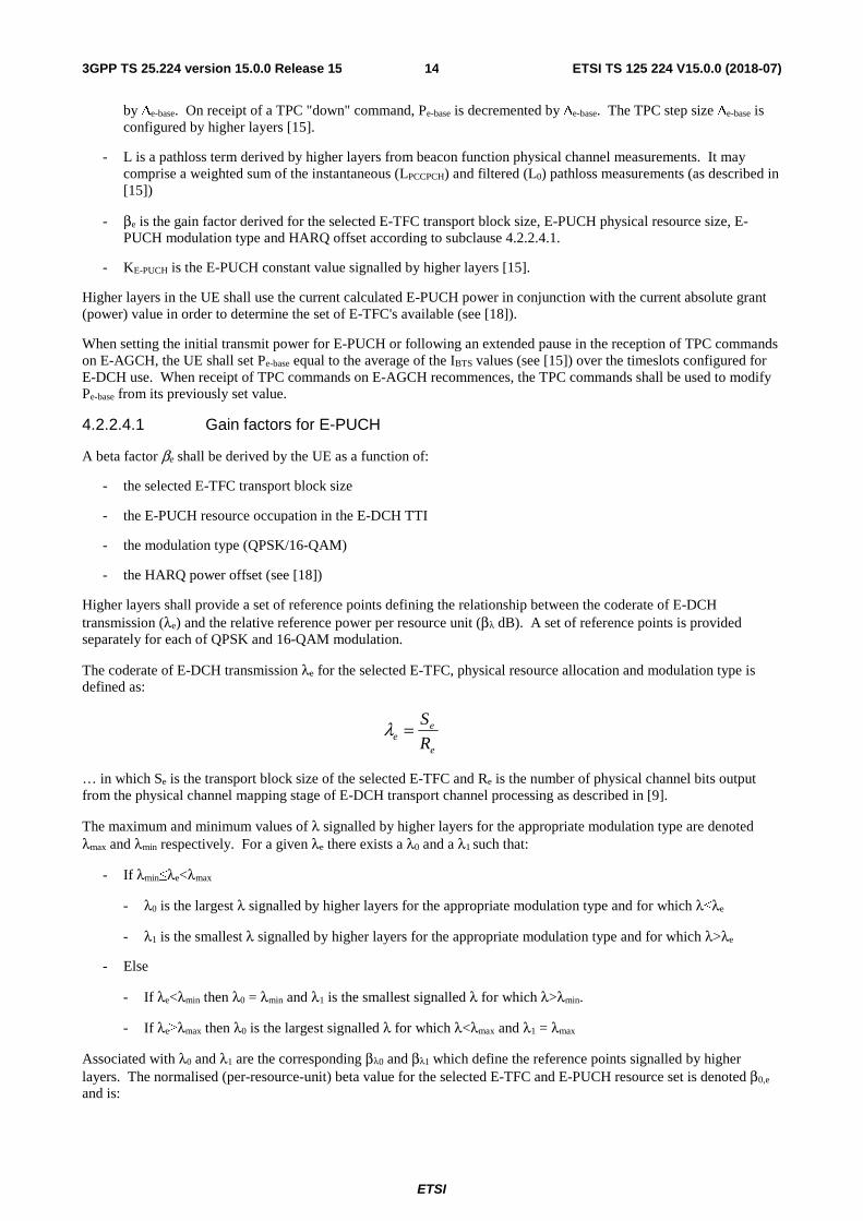
The transmit power of the E-PUCH is calculated in the UE as follows:
PUCHEebaseePUCHE KLPP −−− +++= β
… where:
- Pe-base is a closed-loop quantity maintained by the UE and which is incremented or decremented by a value Δe-base upon each receipt of a TPC command on E-AGCH. On receipt of a TPC "up" command, Pe-base is incremented
=i i
ref SFL
1
=i i
j SFL
1
ETSI
ETSI TS 125 224 V15.0.0 (2018-07)143GPP TS 25.224 version 15.0.0 Release 15
by Δe-base. On receipt of a TPC "down" command, Pe-base is decremented by Δe-base. The TPC step size Δe-base is configured by higher layers [15].
- L is a pathloss term derived by higher layers from beacon function physical channel measurements. It may comprise a weighted sum of the instantaneous (LPCCPCH) and filtered (L0) pathloss measurements (as described in [15])
- βe is the gain factor derived for the selected E-TFC transport block size, E-PUCH physical resource size, E-PUCH modulation type and HARQ offset according to subclause 4.2.2.4.1.
- KE-PUCH is the E-PUCH constant value signalled by higher layers [15].
Higher layers in the UE shall use the current calculated E-PUCH power in conjunction with the current absolute grant (power) value in order to determine the set of E-TFC's available (see [18]).
When setting the initial transmit power for E-PUCH or following an extended pause in the reception of TPC commands on E-AGCH, the UE shall set Pe-base equal to the average of the IBTS values (see [15]) over the timeslots configured for E-DCH use. When receipt of TPC commands on E-AGCH recommences, the TPC commands shall be used to modify Pe-base from its previously set value.
4.2.2.4.1 Gain factors for E-PUCH
A beta factor βe shall be derived by the UE as a function of:
- the selected E-TFC transport block size
- the E-PUCH resource occupation in the E-DCH TTI
- the modulation type (QPSK/16-QAM)
- the HARQ power offset (see [18])
Higher layers shall provide a set of reference points defining the relationship between the coderate of E-DCH transmission (λe) and the relative reference power per resource unit (βλ dB). A set of reference points is provided separately for each of QPSK and 16-QAM modulation.
The coderate of E-DCH transmission λe for the selected E-TFC, physical resource allocation and modulation type is defined as:
e
ee R
S=λ
… in which Se is the transport block size of the selected E-TFC and Re is the number of physical channel bits output from the physical channel mapping stage of E-DCH transport channel processing as described in [9].
The maximum and minimum values of λ signalled by higher layers for the appropriate modulation type are denoted λmax and λmin respectively. For a given λe there exists a λ0 and a λ1 such that:
- If λmin≤λe<λmax
- λ0 is the largest λ signalled by higher layers for the appropriate modulation type and for which λ≤λe
- λ1 is the smallest λ signalled by higher layers for the appropriate modulation type and for which λ>λe
- Else
- If λe<λmin then λ0 = λmin and λ1 is the smallest signalled λ for which λ>λmin.
- If λe≥λmax then λ0 is the largest signalled λ for which λ<λmax and λ1 = λmax
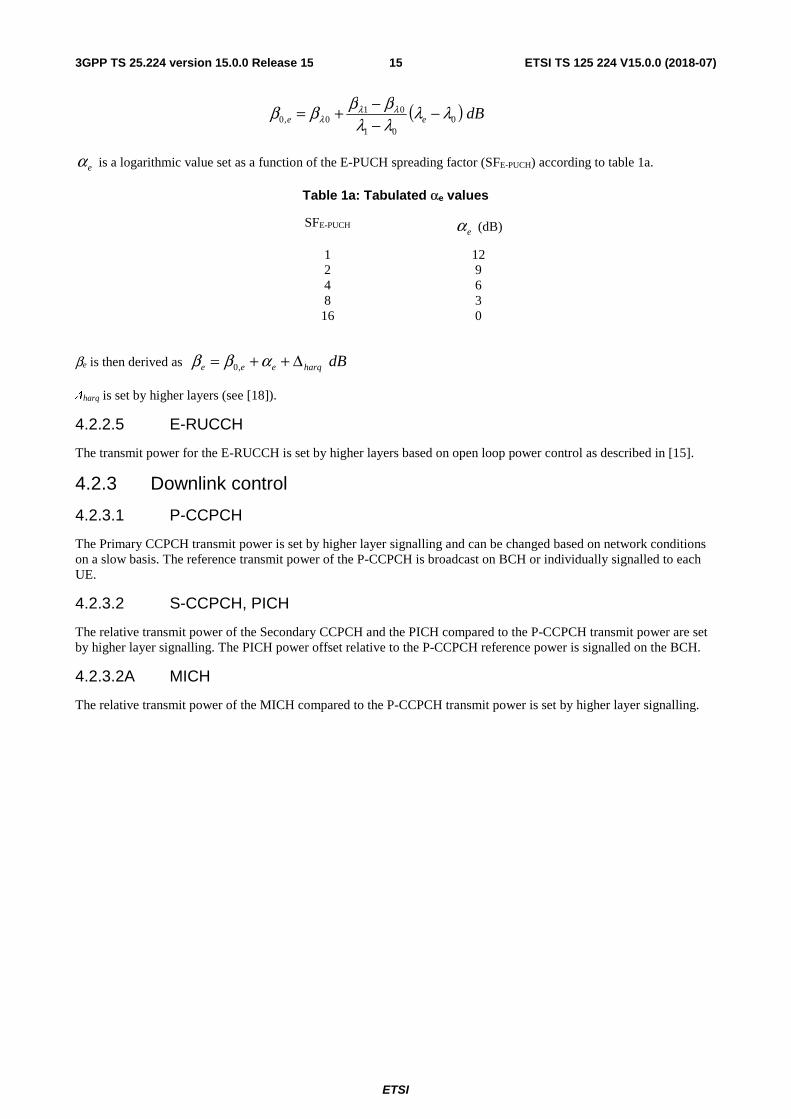
Associated with λ0 and λ1 are the corresponding βλ0 and βλ1 which define the reference points signalled by higher layers. The normalised (per-resource-unit) beta value for the selected E-TFC and E-PUCH resource set is denoted β0,e and is:
ETSI
ETSI TS 125 224 V15.0.0 (2018-07)153GPP TS 25.224 version 15.0.0 Release 15
( ) dBee 001
010,0 λλ
λλββββ λλ
λ −−−+=
eα is a logarithmic value set as a function of the E-PUCH spreading factor (SFE-PUCH) according to table 1a.
Table 1a: Tabulated αe values
SFE-PUCH eα (dB)
1 12 2 9 4 6 8 3 16 0
βe is then derived as dBharqeee Δ++= αββ ,0
Δharq is set by higher layers (see [18]).
4.2.2.5 E-RUCCH
The transmit power for the E-RUCCH is set by higher layers based on open loop power control as described in [15].
4.2.3 Downlink control
4.2.3.1 P-CCPCH
The Primary CCPCH transmit power is set by higher layer signalling and can be changed based on network conditions on a slow basis. The reference transmit power of the P-CCPCH is broadcast on BCH or individually signalled to each UE.
4.2.3.2 S-CCPCH, PICH
The relative transmit power of the Secondary CCPCH and the PICH compared to the P-CCPCH transmit power are set by higher layer signalling. The PICH power offset relative to the P-CCPCH reference power is signalled on the BCH.
4.2.3.2A MICH
The relative transmit power of the MICH compared to the P-CCPCH transmit power is set by higher layer signalling.
ETSI
ETSI TS 125 224 V15.0.0 (2018-07)163GPP TS 25.224 version 15.0.0 Release 15
4.2.3.3 SCH
The SCH transmit power is set by higher layer signalling [16]. The value is given relative to the power of the P-CCPCH.
4.2.3.3A PNBSCH
The PNBSCH transmit power is set by higher layer signalling [16]. The value given is relative to the power of the P-CCPCH
4.2.3.4 DPCH, PDSCH
The initial transmission power of the downlink DPCH and the PDSCH shall be set by higher layer signalling. If associated uplink CCTrCHs for TPC commands are signalled to the UE by higher layers (mandatory for a DPCH), the network shall transit into inner loop power control after the initial transmission. The UE shall then generate TPC commands to control the network transmit power and send them in the TPC field of the associated uplink CCTrCHs. If the physical channel power should be increased, the TPC command is set to "up" whereas if the power should be reduced the TPC command is set to "down". An example on how to derive the TPC commands and the definition of the inner loop power control are given in Annex A.1. A TPC command sent in an uplink CCTrCH controls all downlink DPCHs or PDSCHs to which the associated downlink CCTrCH is mapped to.
If a PDSCH does not have associated uplink CCTrCHs configured for TPC power control, its power shall be controlled by higher layer signalling.
In the case that no associated downlink data is scheduled within 15 timeslots before the transmission of a TPC command then this is regarded as a transmission pause. The TPC commands in this case shall be derived from measurements on beacon function physical channels. An example solution for the generation of the TPC command for this case is given in Annex A 1.
When not in a transmission pause each TPC command shall always be based on all associated downlink transmissions received since the previous related TPC command. Related TPC commands are defined as TPC commands associated with the same downlink CCTrCHs. If there are no associated downlink transmissions (or equivalently no beacon transmissions when in a transmission pause) between two or more uplink transmissions carrying related TPC commands, then these TPC commands shall be identical and they shall be regarded by the UTRAN as a single TPC command.
UTRAN may decide how to adjust the transmit power in response to the received TPC command.
The UTRAN may apply an individual offset to the transmission power in each timeslot according to the downlink interference level at the UE.
The transmission power of one DPCH or PDSCH shall not exceed the limits set by higher layer signalling by means of Maximum_DL_Power (dB) and Minimum_DL_Power (dB). The transmission power is defined as the average power over one timeslot of the complex QPSK symbols of a single DPCH or PDSCH before spreading relative to the power of the P-CCPCH.
During a downlink transmission pause, both UE and Node B shall use the same TPC step size which is signalled by higher layers. The UTRAN may accumulate the TPC commands received during the pause. TPC commands that shall be regarded as identical may only be counted once. The initial UTRAN transmission power for the first data transmission after the pause may then be set to the sum of transmission power before the pause and a power offset according to the accumulated TPC commands. Additionally this sum may include a constant set by the operator and a correction term due to uncertainties in the reception of the TPC bits. The total downlink transmission power at the Node B within one timeslot shall not exceed Maximum Transmission Power set by higher layer signalling. If the total transmit power of all channels in a timeslot exceeds this limit, then the transmission power of all downlink DPCHs and PDSCHs shall be reduced by the same amount in dB. The value for this power reduction is determined, so that the total transmit power of all channels in this timeslot is equal to the maximum transmission power.
ETSI
ETSI TS 125 224 V15.0.0 (2018-07)173GPP TS 25.224 version 15.0.0 Release 15
4.2.3.4.1 Out of synchronisation handling
When the dedicated physical channel out of sync criteria based on the received burst quality is as given in the subclause 4.4.2 then the UE shall set the uplink TPC command = "up". The CRC based criteria shall not be taken into account in TPC bit value setting.
4.2.3.5 HS-PDSCH
The HS-PDSCH power control is under the control of the NodeB.
4.2.3.6 HS-SCCH
Higher layers shall indicate the maximum transmit power of the HS-SCCH. The Node-B shall not exceed this maximum power when setting the HS-SCCH power.
The initial power of the HS-SCCH is at the discretion of the Node-B. Following the initial transmission, the NodeB may optionally power control the HS-SCCH. This may be done using TPC commands sent by the UE in the HS-SICH.
The UE shall set the TPC commands in the HS-SICH in order to control the transmit power of the HS-SCCH. The TPC commands shall be set in order to meet the HS-SCCH target BLER.
The accuracy of the received HS-SCCH BLER estimate made by the UE may be enhanced by a suitable use of the HCSN field received within the HS-SCCH itself [9]. This field shall initially be set to zero and shall be incremented by the NodeB each time an HS-SCCH is transmitted to the UE.
4.2.3.7 E-AGCH
Higher layers shall indicate the maximum transmit power of the E-AGCH. The Node-B shall not exceed this maximum power when setting the E-AGCH power.
The initial power of the E-AGCH is at the discretion of the Node-B. Following the initial transmission, the NodeB may optionally power control the E-AGCH. This may be done using TPC commands sent by the UE in the E-PUCH.
The UE shall set the TPC commands in the E-PUCH in order to control the transmit power of the E-AGCH. The TPC commands shall be set in order to meet the E-AGCH target BLER.
The accuracy of the received E-AGCH BLER estimate made by the UE shall be enhanced by a suitable use of the ECSN field received within the E-AGCH itself [9]. This field shall initially be set to zero and shall be incremented by the Node-B each time an E-AGCH is transmitted to the UE.
4.2.3.8 E-HICH
The power of the E- HICH is under the control of the Node B.
4.3 Timing advance UTRAN may adjust the UE transmission timing with timing advance. The initial value for timing advance (TAphys) will be determined in the UTRAN by measurement of the timing of the PRACH or E-RUCCH. The required timing advance will be represented as an 8 bit number (0-255) 'UL Timing Advance' TAul, being the multiplier of 4 chips which is nearest to the required timing advance (i.e. TAphys = TAul × 4 chips).
When Timing Advance is used the UTRAN will continuously measure the timing of a transmission from the UE and send the necessary timing advance value. On receipt of this value the UE shall adjust the timing of its transmissions accordingly in steps of ±4chips. The transmission of TA values is done by means of higher layer messages. Upon receiving the TA command the UE shall adjust its transmission timing according to the timing advance command at the frame number specified by higher layer signaling. The UE is signaled the TA value in advance of the specified frame activation time to allow for local processing of the command and application of the TA adjustment on the specified frame. Node-B is also signaled the TA value and radio frame number that the TA adjustment is expected.to take place.
If TA is enabled by higher layers, after handover the UE shall transmit in the new cell with timing advance TA adjusted by the relative timing difference Δt between the new and the old cell:
TAnew = TAold + 2Δt.
ETSI
ETSI TS 125 224 V15.0.0 (2018-07)183GPP TS 25.224 version 15.0.0 Release 15
4.4 Synchronisation procedures
4.4.1 Cell search
During the cell search, the UE searches for a cell and determines the downlink scrambling code, basic midamble code and frame synchronisation of that cell. How cell search is typically done is described in Annex C.
For MBSFN FACH, the downlink scrambling codes and basic midamble codes to be used for non-beacon timeslots are signalled by higher layers.
4.4.2 Dedicated channel synchronisation
4.4.2.1 Synchronisation primitives
4.4.2.1.1 General
For the dedicated channels, synchronisation primitives are used to indicate the synchronisation status of radio links, both in uplink and downlink. The definition of the primitives is given in the following subclauses.
When operating HS-DSCH, the configuration of a downlink DPCH by UTRAN is optional. Subclause 4.4.2.1.2 relates to downlink synchronisation in the case that an uplink and downlink DPCH have been configured by higher layers. Subclause 4.4.2.1.2A relates to downlink synchronisation in the case that only an uplink DPCH has been configured by higher layers.
4.4.2.1.2 Downlink synchronisation primitives
Layer 1 in the UE shall check the synchronization status of each DL CCTrCH individually in every radio frame All bursts and transport channels of a CCTrCH shall be taken into account. Synchronisation status is indicated to higher layers, using the CPHY-Sync-IND or CPHY-Out-of-Sync-IND primitives. For dedicated physical channels configured with Repetition Periods [15 ] only the configured active periods shall be taken into account in the estimation. The status check shall also include detection of the Special Bursts defined in 4.5 for DTX.
The criteria for reporting synchronization status are defined in two different phases.
The first phase lasts until 160 ms after the downlink CCTrCH is considered to be established by higher layers. During this time, Out-of-sync shall not be reported. In-sync shall be reported using the CPHY-Sync-IND primitive if any one of the following three criteria is fulfilled.
a) The UE estimates the burst reception quality over the previous 40 ms period to be better than a threshold Qin. This criterion shall be assumed not to be fulfilled before 40 ms of burst reception quality measurement have been collected.
b) At least one transport block with a CRC attached is received in a TTI ending in the current frame with correct CRC.
c) The UE detects at least one Special Burst. Special Burst detection shall be successful if the burst is detected with quality above a threshold, Qsbin, and the TFCI is decoded to be that of the Special Burst.
The second phase starts 160 ms after the downlink dedicated channel is considered established by higher layers.. During this phase both Out-of-Sync and In-Sync are reported as follows.
Out-of-sync shall be reported using the CPHY-Out-of-Sync-IND primitive if all three of the following criteria are fulfilled:
- the UE estimates the received dedicated channel burst quality over the last 160 ms period to be worse than a threshold Qout. The value, Qout is defined implicitly by the relevant tests in [2];
- no Special Burst is detected with quality above a threshold Qsbout within the last 160 ms period. The value Qsbout is defined implicitly by the relevant tests in [2];
- over the previous 160 ms, no transport block has been received with a correct CRC
If the UE detects the beacon channel reception level [10 dB] above the handover triggering level, the UE shall use 320 ms estimation period for the burst quality evaluation and for the Special Burst and CRC detection window.
ETSI
ETSI TS 125 224 V15.0.0 (2018-07)193GPP TS 25.224 version 15.0.0 Release 15
In-sync shall be reported using the CPHY-Sync-IND primitive if any of the following criteria is fulfilled:
- the UE estimates the received burst reception quality over the last 160 ms period to be better than a threshold Qin. The value, Qin is defined implicitly by the relevant tests in [2].
- the UE detects at least one Special Burst with quality above a threshold Qsbin within the last 160 ms period. The value, Qsbin, is defined implicitly by the relevent tests in [2].
- at least one transport block with a CRC attached is received in a TTI ending in the current frame with correct CRC.
If the UE detects the beacon channel reception level [10 dB] above the handover triggering level, the UE uses 320 ms estimation period for the burst quality evaluation and for the Special Burst detection window.
If no data are provided by higher layers for transmission during the second phase on the downlink dedicated channel then DTX shall be applied as defined in section 4.5.
How the primitives are used by higher layers is described in [15]. The above definitions may lead to radio frames where neither the In-Sync nor Out-of-Sync primitives are reported.
4.4.2.1.2A Downlink synchronisation primitives for HS-channels
In the case that an uplink DPCH has been configured by higher layers but a downlink DPCH has not been configured, the UE shall report downlink synchronisation status based upon other downlink physical channels.
The UE shall monitor the received beacon signal level within the cell and shall average the received beacon power over a period of 160ms. This averaged value is denoted Pb dBm. The UE shall also monitor and average over the same period, the ISCP on the assigned HS-SCCH resources. This value is denoted IHS-SCCH dBm. A quality value Qhs is formed as follows:
Qhs = Pb – IHS-SCCH + Dhs-sync
- where Dhs-sync is signalled by higher layers.
In-sync shall be reported using the CPHY-Sync-IND primitive each time an HS-DSCH CRC pass is detected. On this event, an indicator maintained by the UE termed "HS-DSCH_failure" shall be set to 'false'. In-sync shall also be reported if the HS-DSCH_failure indicator is set to 'false' and during the last 160ms period, Qhs > Qhsin, where Qhsin is a quality threshold defined implicitly by the relevant tests in [2].
Out-of-sync shall be reported using the CPHY-Out-of-Sync-IND primitive. "Out-of-sync" is generated in the event that, during the last 160ms period, Qhs < Qhsout, where Qhsout is a quality threshold defined implicitly by the relevant tests in [2]. CPHY-Out-of-Sync-IND shall also be generated in the event of 16 successive HS-DSCH CRC failures. On occurrence of this event, the HS-DSCH_failure indicator shall be set to 'true'.
How the primitives are used by higher layers is described in [15]. The above definitions may lead to radio frames where neither the In-Sync nor Out-of-Sync primitives are reported. They may also, under some circumstances, lead to radio frames in which both In-Sync and Out-of-Sync primitives are generated. In this instance, In-sync shall override Out-of-Sync and the Out-of-Sync primitive shall not be reported.
4.4.2.1.3 Uplink synchronisation primitives
Layer 1 in the Node B shall every radio frame check synchronisation status, individually for each UL CCTrCH of the radio link. Synchronisation status is indicated to the RL Failure/Restored triggering function using either the CPHY-Sync-IND or CPHY-Out-of-Sync-IND primitive.
The exact criteria for indicating in-sync/out-of-sync is not subject to specification, but could e.g. be based on received burst quality or CRC checks. One example would be to have the same criteria as for the downlink synchronisation status primitives.
4.4.2.2 Radio link monitoring
4.4.2.2.1 Downlink radio link failure
The downlink CCTrCHs are monitored by the UE, to trigger radio link failure procedures. The downlink CCTrCH failure status is specified in [15], and is based on the synchronisation status primitives CPHY-Sync-IND and CPHY-
ETSI
ETSI TS 125 224 V15.0.0 (2018-07)203GPP TS 25.224 version 15.0.0 Release 15
Out-of-Sync-IND, indicating in-sync and out-of-sync respectively. These primitives shall provide status for each DL CCTrCH separately.
4.4.2.2.2 Uplink radio link failure/restore
The uplink CCTrCHs are monitored by the Node B in order to trigger CCTrCH failure/restore procedures. The uplink CCTrCH failure/restore status is reported using the synchronisation status primitives CPHY-Sync-IND and CPHY-Out-of-Sync-IND, indicating in-sync and out-of-sync respectively.
When the CCTrCH is in the in-sync state, Node B shall start timer T_RLFAILURE after receiving N_OUTSYNC_IND consecutive out-of-sync indications. Node B shall stop and reset timer T_RLFAILURE upon receiving successive N_INSYNC_IND in-sync indications. If T_RLFAILURE expires, Node B shall indicate to higher layers which CCTrCHs are out-of-sync using the synchronization status primitives. Furthermore, the CCTrCH state shall be changed to the out-of-sync state.
When a CCTrCH is in the out-of-sync state, after receiving N_INSYNC_IND successive in-sync indications Node B shall indicate that the CCTrCH has re-established synchronisation and the CCTrCH's state shall be changed to the in-sync-state. The specific parameter settings (values of T_RLFAILURE, N_OUTSYNC_IND, and N_INSYNC_IND) are configurable, see [16].
4.5 Discontinuous transmission (DTX) procedure The DTX procedure shall be applied for CCTrCHs mapped to S-CCPCH, UL DPCH, DL DPCH, PUSCH and PDSCH, if the total bit rate of the CCTrCH differs from the total channel bit rate of the physical channels allocated to this CCTrCH. DTX shall not be applied to E-DCH mapped to E-PUCH.
The DTX procedure shall also be applied to HS-PDSCHs, HS-SCCHs, E-AGCHs and E-HICHs if no data is to be transmitted on these physical channels in a given TTI.
Rate matching is used in order to fill resource units completely, that are only partially filled with data. In the case that after rate matching and multiplexing no data at all is to be transmitted in a resource unit the complete resource unit shall be discarded from transmission (DTX), unless a Special Burst is transmitted in the RU. This applies also to the case where only one resource unit is allocated and no data has to be transmitted.
4.5.1 Description of special bursts
For S-CCPCH, UL DPCH, DL DPCH, PUSCH and PDSCH, the Special Burst has the same timeslot format as the burst used for data provided by higher layers. If the timeslot format contains a TFCI field, then the TFCI field shall be filled with "0" bits. The Special Burst may also carry layer 1 control symbols such as TPC bits for the purposes of inner-loop power control. The data portions of the Special Burst are filled with an arbitrary bit pattern.
For S-CCPCH, UL DPCH, DL DPCH, PUSCH and PDSCH, the transmission power of the special burst shall be the same as that of the substituted physical channel of the CCTrCH. In the case of uplink physical channels where autonomous spreading factor change by the UE is permitted by higher layers, the substituted physical channel is considered to be that which would have been employed for the lowest non-zero rate TFC within the set of allowed TFC's and the transmission power of the Special Burst shall again correspond to that of the physical channel substituted.
For HS-PDSCH, the Special Burst shall use the timeslot format #0 from table 7a, see section 5.3.9.5 in [8]. For HS-SCCH, the Special Burst shall use timeslot format #0 from table 5a, see section 5.2.2.6.1 in [8]. The Special Burst is filled with an arbitrary bit pattern. The transmission power of the Special Burst shall be the same as that of the substituted Beacon channel.
4.5.2 Use of special bursts during DTX
In the case that after link establishment there are no transport blocks provided for transmission by higher layers for a given CCTrCH mapped to UL DPCH, DL DPCH, PUSCH or PDSCH physical channels, then a Special Burst shall be transmitted in the first allocated frame of the transmission pause. If, including the first frame, there is a consecutive period of Special Burst Period (SBP) frames without transport blocks provided by higher layers, then another special burst shall be generated and transmitted at the next possible frame. This pattern shall be continued until transport blocks are provided for the CCTrCH by the higher layers. SBP shall be provided by higher layers. The value of SBP shall be independently specified for uplink and for downlink and shall be designated as
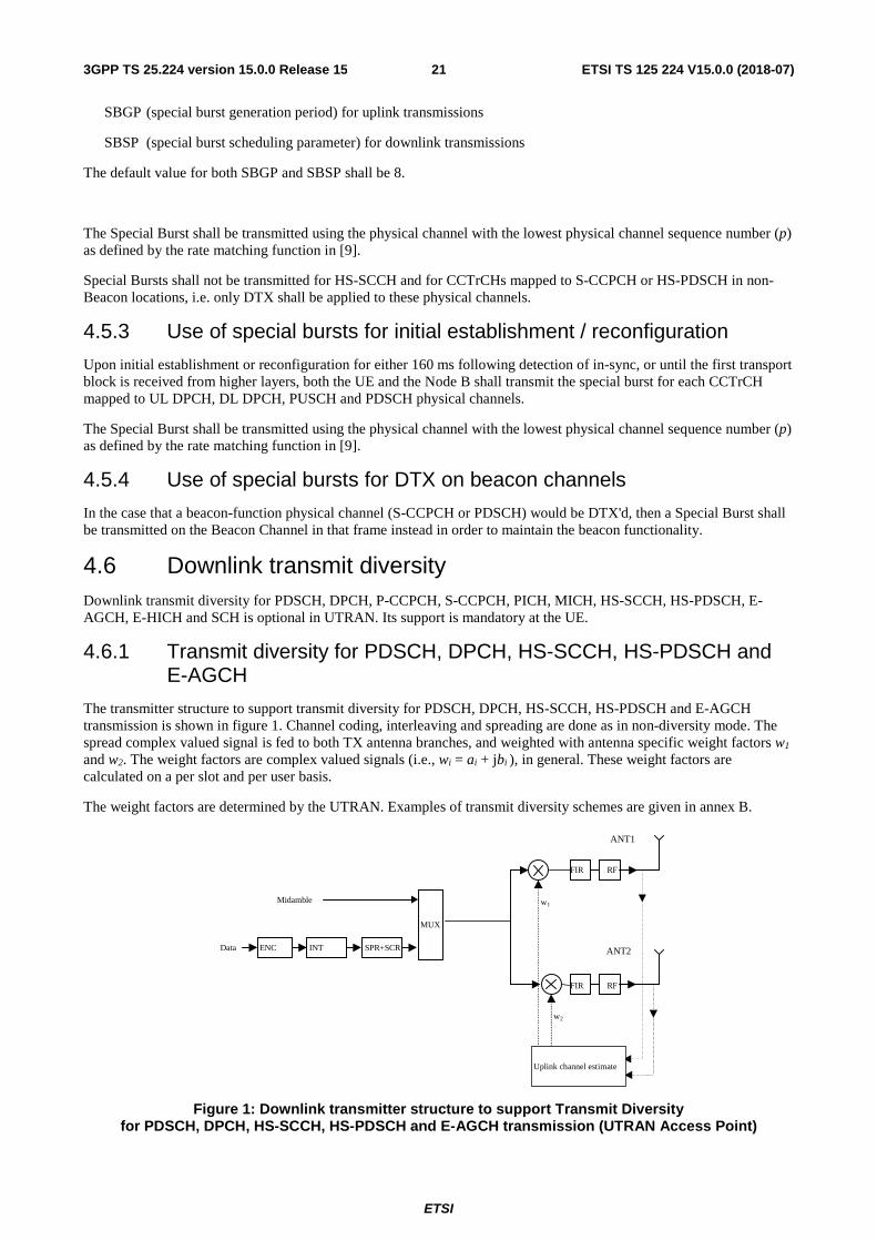
ETSI
ETSI TS 125 224 V15.0.0 (2018-07)213GPP TS 25.224 version 15.0.0 Release 15
SBGP (special burst generation period) for uplink transmissions
SBSP (special burst scheduling parameter) for downlink transmissions
The default value for both SBGP and SBSP shall be 8.
The Special Burst shall be transmitted using the physical channel with the lowest physical channel sequence number (p) as defined by the rate matching function in [9].
Special Bursts shall not be transmitted for HS-SCCH and for CCTrCHs mapped to S-CCPCH or HS-PDSCH in non-Beacon locations, i.e. only DTX shall be applied to these physical channels.
4.5.3 Use of special bursts for initial establishment / reconfiguration
Upon initial establishment or reconfiguration for either 160 ms following detection of in-sync, or until the first transport block is received from higher layers, both the UE and the Node B shall transmit the special burst for each CCTrCH mapped to UL DPCH, DL DPCH, PUSCH and PDSCH physical channels.
The Special Burst shall be transmitted using the physical channel with the lowest physical channel sequence number (p) as defined by the rate matching function in [9].
4.5.4 Use of special bursts for DTX on beacon channels
In the case that a beacon-function physical channel (S-CCPCH or PDSCH) would be DTX'd, then a Special Burst shall be transmitted on the Beacon Channel in that frame instead in order to maintain the beacon functionality.
4.6 Downlink transmit diversity Downlink transmit diversity for PDSCH, DPCH, P-CCPCH, S-CCPCH, PICH, MICH, HS-SCCH, HS-PDSCH, E-AGCH, E-HICH and SCH is optional in UTRAN. Its support is mandatory at the UE.
4.6.1 Transmit diversity for PDSCH, DPCH, HS-SCCH, HS-PDSCH and E-AGCH
The transmitter structure to support transmit diversity for PDSCH, DPCH, HS-SCCH, HS-PDSCH and E-AGCH transmission is shown in figure 1. Channel coding, interleaving and spreading are done as in non-diversity mode. The spread complex valued signal is fed to both TX antenna branches, and weighted with antenna specific weight factors w1
and w2. The weight factors are complex valued signals (i.e., wi = ai + jbi ), in general. These weight factors are calculated on a per slot and per user basis.
The weight factors are determined by the UTRAN. Examples of transmit diversity schemes are given in annex B.
Figure 1: Downlink transmitter structure to support Transmit Diversity for PDSCH, DPCH, HS-SCCH, HS-PDSCH and E-AGCH transmission (UTRAN Access Point)
MUX
INTENCData
Midamble w1
w2
FIR RF
FIR RF
Uplink channel estimate
ANT1
ANT2SPR+SCR
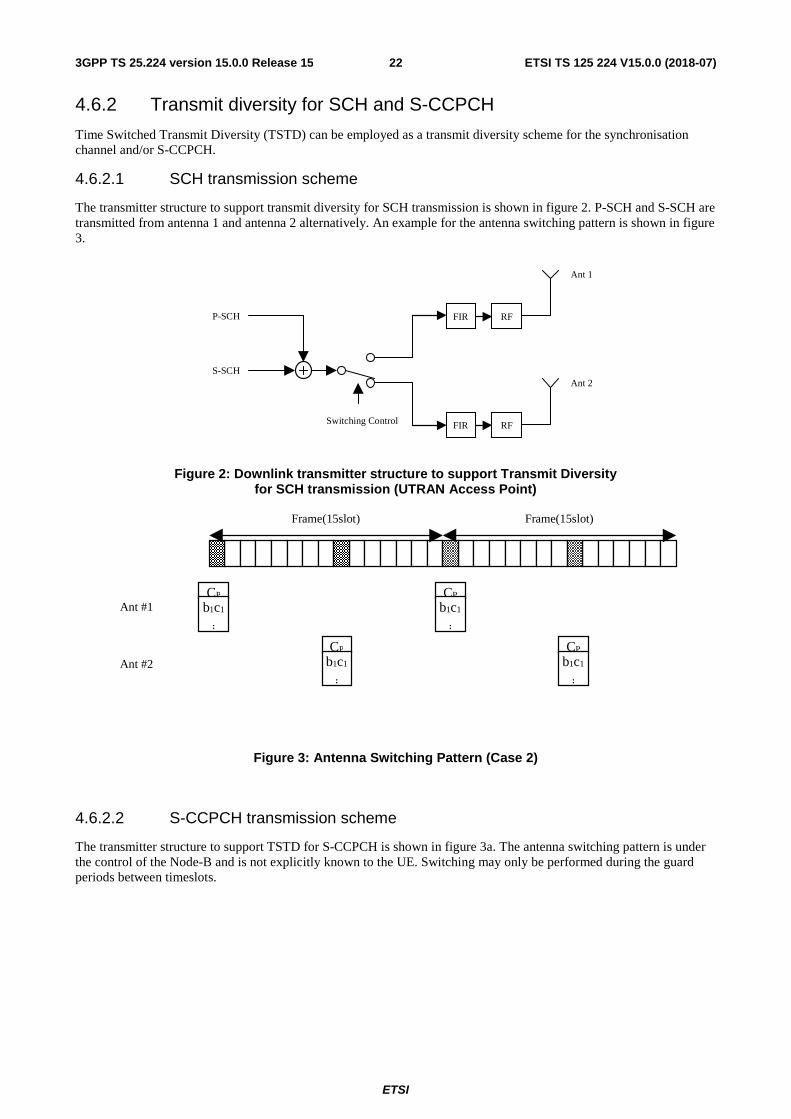
ETSI
ETSI TS 125 224 V15.0.0 (2018-07)223GPP TS 25.224 version 15.0.0 Release 15
4.6.2 Transmit diversity for SCH and S-CCPCH
Time Switched Transmit Diversity (TSTD) can be employed as a transmit diversity scheme for the synchronisation channel and/or S-CCPCH.
4.6.2.1 SCH transmission scheme
The transmitter structure to support transmit diversity for SCH transmission is shown in figure 2. P-SCH and S-SCH are transmitted from antenna 1 and antenna 2 alternatively. An example for the antenna switching pattern is shown in figure 3.
Figure 2: Downlink transmitter structure to support Transmit Diversity for SCH transmission (UTRAN Access Point)
Figure 3: Antenna Switching Pattern (Case 2)
4.6.2.2 S-CCPCH transmission scheme
The transmitter structure to support TSTD for S-CCPCH is shown in figure 3a. The antenna switching pattern is under the control of the Node-B and is not explicitly known to the UE. Switching may only be performed during the guard periods between timeslots.
S-SCH
FIR RF
P-SCH
Ant 2
FIR RF
Ant 1
Switching Control
Frame(15slot) Frame(15slot)
Ant #1
Ant #2
CP
b1c1
:
CP
b1c1
:
CP
b1c1
:
CP
b1c1
:
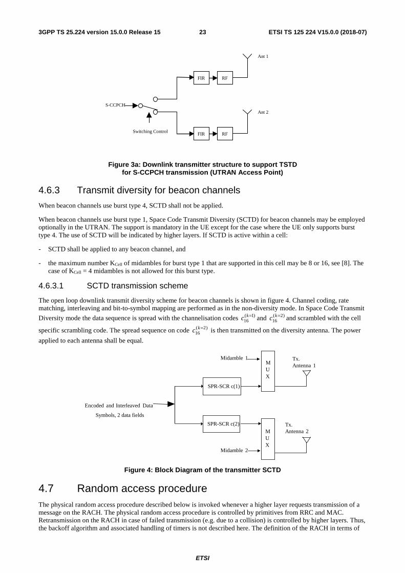
ETSI
ETSI TS 125 224 V15.0.0 (2018-07)233GPP TS 25.224 version 15.0.0 Release 15
S-CCPCH
FIR RF
Ant 2
FIR RF
Ant 1
Switching Control
Figure 3a: Downlink transmitter structure to support TSTD for S-CCPCH transmission (UTRAN Access Point)
4.6.3 Transmit diversity for beacon channels
When beacon channels use burst type 4, SCTD shall not be applied.
When beacon channels use burst type 1, Space Code Transmit Diversity (SCTD) for beacon channels may be employed optionally in the UTRAN. The support is mandatory in the UE except for the case where the UE only supports burst type 4. The use of SCTD will be indicated by higher layers. If SCTD is active within a cell:
- SCTD shall be applied to any beacon channel, and
- the maximum number KCell of midambles for burst type 1 that are supported in this cell may be 8 or 16, see [8]. The case of KCell = 4 midambles is not allowed for this burst type.
4.6.3.1 SCTD transmission scheme
The open loop downlink transmit diversity scheme for beacon channels is shown in figure 4. Channel coding, rate matching, interleaving and bit-to-symbol mapping are performed as in the non-diversity mode. In Space Code Transmit
Diversity mode the data sequence is spread with the channelisation codes and and scrambled with the cell
specific scrambling code. The spread sequence on code is then transmitted on the diversity antenna. The power
applied to each antenna shall be equal.
Figure 4: Block Diagram of the transmitter SCTD
4.7 Random access procedure The physical random access procedure described below is invoked whenever a higher layer requests transmission of a message on the RACH. The physical random access procedure is controlled by primitives from RRC and MAC. Retransmission on the RACH in case of failed transmission (e.g. due to a collision) is controlled by higher layers. Thus, the backoff algorithm and associated handling of timers is not described here. The definition of the RACH in terms of
)1(16
=kc )2(16
=kc)2(
16=kc
Tx.Antenna 1
Tx.Antenna 2
Encoded and Interleaved Data
Midamble 2
MUX
MUX
Midamble 1
SPR-SCR c(1)
SPR-SCR c(2)
Symbols, 2 data fields
ETSI
ETSI TS 125 224 V15.0.0 (2018-07)243GPP TS 25.224 version 15.0.0 Release 15
PRACH Access Service Classes is broadcast on the BCH in each cell. Parameters for common physical channel uplink outer loop power control are also broadcast on the BCH in each cell. The UE needs to decode this information prior to transmission on the RACH. Higher layer signalling may indicate, that in some frames a timeslot shall be blocked for RACH uplink transmission.
4.7.1 Physical random access procedure
The physical random access procedure described in this subclause is initiated upon request from the MAC sublayer (see [18] and [19]).
Note: The selection of a PRACH is done by the RRC Layer.
Before the physical random-access procedure can be initiated, Layer 1 shall receive the following information from the RRC layer using the primitives CPHY-TrCH-Config-REQ and CPHY-RL-Setup/Modify-REQ.
- the available PRACH channelization codes (There is a 1-1 mapping between the channelization code and the midamble shift as defined by RRC) for each Access Service Class (ASC) of the selected PRACH (the selection of a PRACH is done by the RRC ). CPHY-RL-Setup/Modify-REQ);
- the timeslot, spreading factor, and midamble type(direct or inverted) for the selected PRACH (CPHY-RL-Setup/Modify-REQ);
- the RACH Transport Format (CPHY-TrCH-Config-REQ);
- the RACH transport channel identity (CPHY-TrCH-Config-REQ)
- the set of parameters for common physical channel uplink outer loop power control(CPHY-RL-Setup/Modify-REQ).
NOTE: The above parameters may be updated from higher layers before each physical random access procedure is initiated.
At each initiation of the physical random access procedure, Layer 1 shall receive the following information from the MAC:
- the ASC of the PRACH transmission;
- the data to be transmitted (Transport Block Set).
the selected ASC sub-channel. The ASC subchannel is defined in reference [18]. The value is passed in the PHY-Data-REQ is the CFNCELL.
In addition, Layer 1 may receive information from higher layers, that a timeslot in certain frames shall be blocked for PRACH uplink transmission.
The physical random-access procedure shall be performed as follows:
1 Randomly select one channelization code from the set of available codes for the selected ASC. The random function shall be such that each code is chosen with equal probability.
2 Determine the midamble shift to use, based on the selected channelization code.
3 Set the PRACH message transmission power level according to the specification for common physical channels in uplink (see subclause 4.2.2.2).
4 Transmit the RACH Transport Block Set (the random access message) with no timing advance in the selected sub-channel using the selected channelization code.
4.7A E-RUCCH transmission procedure Requests for the transmission of an E-RUCCH are controlled by higher layers [18].
The E-RUCCH random access procedure shall be performed as follows:
1 Randomly select one channelization code from the set of available codes for E-RUCCH. The random function shall be such that each code is chosen with equal probability.
ETSI
ETSI TS 125 224 V15.0.0 (2018-07)253GPP TS 25.224 version 15.0.0 Release 15
2 Determine the midamble shift to use, based on the selected channelization code.
3 Set the E-RUCCH message transmission power level according to subclause 4.2.2.5.
4 Transmit the E-RUCCH with no timing advance using the selected channelization code.
4.8 DSCH procedure The physical downlink shared channel procedure described below shall be applied by the UE when the physical layer signalling either with the midamble based signalling or TFCI based signalling is used to indicate for the UE the need for PDSCH detection. There is also a third alternative to indicate to the UE the need for the PDSCH detection and this is done by means of higher layer signalling, already described in [8].
4.8.1 DSCH procedure with TFCI indication
When the UE has been allocated by higher layers to receive data on DSCH using the TFCI, the UE shall decode the PDSCH in the following cases:
- In case of a standalone PDSCH the TFCI is located on the PDSCH itself, then the UE shall decode the TFCI and based on which data rate was indicated by the TFCI, the decoding shall be performed. The UE shall decode PDSCH only if the TFCI word decode corresponds to the TFC part of the TFCS given to the UE by higher layers.
- In case that the TFCI is located on the DCH, the UE shall decode the PDSCH frame or frames if the TFCI on the DCH indicates the need for PDSCH reception. Upon reception of the DCH time slot or time slots, the PDSCH slot (or first PDSCH slot) shall start SFN n+2 after the DCH frame containing the TFCI, where n indicates the SFN on which the DCH is received. In the case that the TFCI is repeated over several frames, the PDSCH slot shall start SFN n+2 after the frame having the DCH slot which contains the last part of the repeated TFCI.
4.8.2 DSCH procedure with midamble indication
When the UE has been allocated by higher layers to receive PDSCH based on the midamble used on the PDSCH (midamble based signalling described in [8]), the UE shall operate as follows:
- The UE shall test the midamble it received and if the midamble received was the same as indicated by higher layers to correspond to PDSCH reception, the UE shall detect the PDSCH data according to the TF given by the higher layers for the UE.
- In case of multiple time slot allocation for the DSCH indicated to be part of the TF for the UE, the UE shall receive all timeslots if the midamble of the first timeslot of PDSCH was the midamble indicated to the UE by higher layers.
- In case the standalone PDSCH (no associated DCH) contains the TFCI the UE shall detect the TF indicated by the TFCI on PDSCH.
4.9 Node B synchronisation procedure over the air An option exists to use cell sync bursts to achieve and maintain Node B synchronisation [20]. This optional procedure is based on transmissions of cell synchronisation bursts [10] in predetermined timeslots normally assigned to contain PRACH, according to an RNC schedule. Such soundings between neighbouring cells facilitate timing offset measurements by the cells. The timing offset measurements are reported back to the RNC for processing. The RNC generates cell timing updates that are transmitted to the Node Bs and cells for implementation.
When Cell Sync Bursts are used to achieve and maintain intercell Synchronisation there are three distinct phases, with a potential additional sub-phase involving late entrant cells.
4.9.1 Frequency acquisition phase
The frequency acquisition phase is used to bring cells of an RNS area to within frequency limits prior to initial synchronisation. No traffic is supported during this phase. In this phase cell(s) identified as master time reference shall transmit cell sync bursts [10] specified by higher layers continuously, i. e. one in every timeslot. All other cells shall listen for transmissions and shall perform frequency locking to the transmissions received. They shall signal
ETSI
ETSI TS 125 224 V15.0.0 (2018-07)263GPP TS 25.224 version 15.0.0 Release 15
completion of frequency acquisition to the RNC and begin continuous transmission of cell sync bursts specified by higher layers.
4.9.2 Initial synchronisation
For Initial Phase, where no traffic is supported, the following procedure for initial synchronisation may be used to bring cells of an RNS area into synchronisation at network start up. In this phase each cell shall transmit cell sync bursts [10] according to the higher layer command. All cells use the same cell sync burst code and code offset. Each cell shall listen for transmissions from other cells. Each cell shall report the timing and received SIR of successfully detected cell sync bursts to the RNC. The RNC uses these measurements to adjust the timing of each cell to achieve the required synchronisation accuracy.
4.9.3 Steady-state phase
The steady-state phase is used to maintain the required synchronisation accuracy. With the start of the steady-state phase, traffic is supported in a cell. A procedure that may be used for the steady-state phase involves cell synch bursts [10] that are transmitted and received without effect on existing traffic. Higher layers signal the transmit parameters, i.e., when to transmit which code and code offset, and which transmit power to use. The higher layers also signal to appropriate cells the receive parameters i. e. which codes and code offsets to measure in a certain timeslot. Upon determination of errors in timing, the RNC may adjust the timing of a cell or cells.
4.9.4 Late entrant cells
A procedure that may be used for introducing new cells into an already synchronised RNS involves the one time transmission of a single cell sync burst [10] (scheduled by higher layers) by all neighbour cells of the late entrant cell. and received by the late entrant cell. The RNC may use this information to adjust the late entrant cell sufficiently to allow the cell to enter steady state phase.
4.10 Idle periods for IPDL location method
4.10.1 General
To support time difference measurements for location services, idle periods can be created in the downlink (hence the name IPDL) during which time transmission of all channels from a Node B is temporarily ceased, except for the SCH transmission. During these idle periods the visibility of neighbour cells from the UE is improved.
The idle periods are arranged in a determined pattern according to higher layer parameters. An idle period has a duration of one time slot. During idle periods only the SCH is transmitted. No attempt is made to prevent data loss.
In general there are two modes for these idle periods:
- Continuous mode, and
- Burst mode.
In continuous mode the idle periods are active all the time. In burst mode the idle periods are arranged in bursts where each burst contains enough idle periods to allow a UE to make sufficient measurements for its location to be calculated. The bursts are separated by a period where no idle periods occur.
The time difference measurements can be performed on any channel. If the P-CCPCH falls in an idle slot, UTRAN may decide not to transmit the P-CCPCH in two consecutive frames, the first of these two frames containing the idle slot. This option is signalled by higher layers.
4.10.2 Parameters of IPDL
The following parameters are signalled to the UE via higher layers:
IP_Status: This is a logic value that indicates if the idle periods are arranged in continuous or burst mode.
IP_Spacing: The number of 10 ms radio frames between the start of a radio frame that contains an idle period and the next radio frame that contains the next idle period. Note that there is at most one idle period in a radio frame.
ETSI
ETSI TS 125 224 V15.0.0 (2018-07)273GPP TS 25.224 version 15.0.0 Release 15
IP_Start: The number of the first frame with idle periods. In case of continuous mode IP_Start is the SFN of the first frame with idle periods and in case of burst mode IP_Start defines the number of frames after Burst_Start with the first frame with idle periods.
IP_Slot: The number of the slot that has to be idle [0..14].
IP_PCCPCH: This logic value indicates, if the P-CCPCH is switched off in two consecutive frames. The first of these two frames contains the idle period.
Additionally in the case of burst mode operation the following parameters are also communicated to the UE.
Burst_Start: Specifies the start of the first burst of idle periods. 256×Burst_Start is the SFN where the first burst of idle periods starts.
Burst_Length: The number of idle periods in a burst of idle periods.
Burst_Freq: Specifies the time between the start of a burst and the start of the next burst. 256×Burst_Freq is the number of radio frames between the start of a burst and the start of the next burst.
4.10.3 Calculation of idle period position
In burst mode, burst #0 starts in the radio frame with SFN = 256×Burst_Start. Burst #n starts in the radio frame with SFN = 256×Burst_Start + n×256×Burst_Freq ( n = 0,1,2, …). The sequence of bursts according to this formula continues up to and including the radio frame with SFN = 4095. At the start of the radio frame with SFN = 0, the burst sequence is terminated (no idle periods are generated) and at SFN = 256×Burst_Start the burst sequence is restarted with burst #0 followed by burst #1 etc., as described above.
Continuous mode is equivalent to burst mode, with only one burst spanning the whole SFN cycle of 4096 radio frames, this burst starts in the radio frame with SFN = 0. In case of continuous mode the parameter IP_Start defines the first frame with idle periods.
The position of an idle period is defined by two values: IP_Frame(x) and IP_Slot. IP_Frame(x) defines the xth frame within a burst that contains the idle period. IP_Slot defines the slot in that frame during which no transmission takes place except for the SCH.
The actual frame with idle periods within a burst is calculated as follows:
IP_Frame(x) = IP_Start + (x-1) × IP_Spacing with x = 1, 2, 3, ....
If the parameter IP_PCCPCH is set to 1, then the P-CCPCH will not be transmitted in the frame IP_Frame(x) +1 within a burst.
Figure 5 below illustrates the idle periods for the burst mode case, if the IP_P-CCPCH parameter is set to 0.
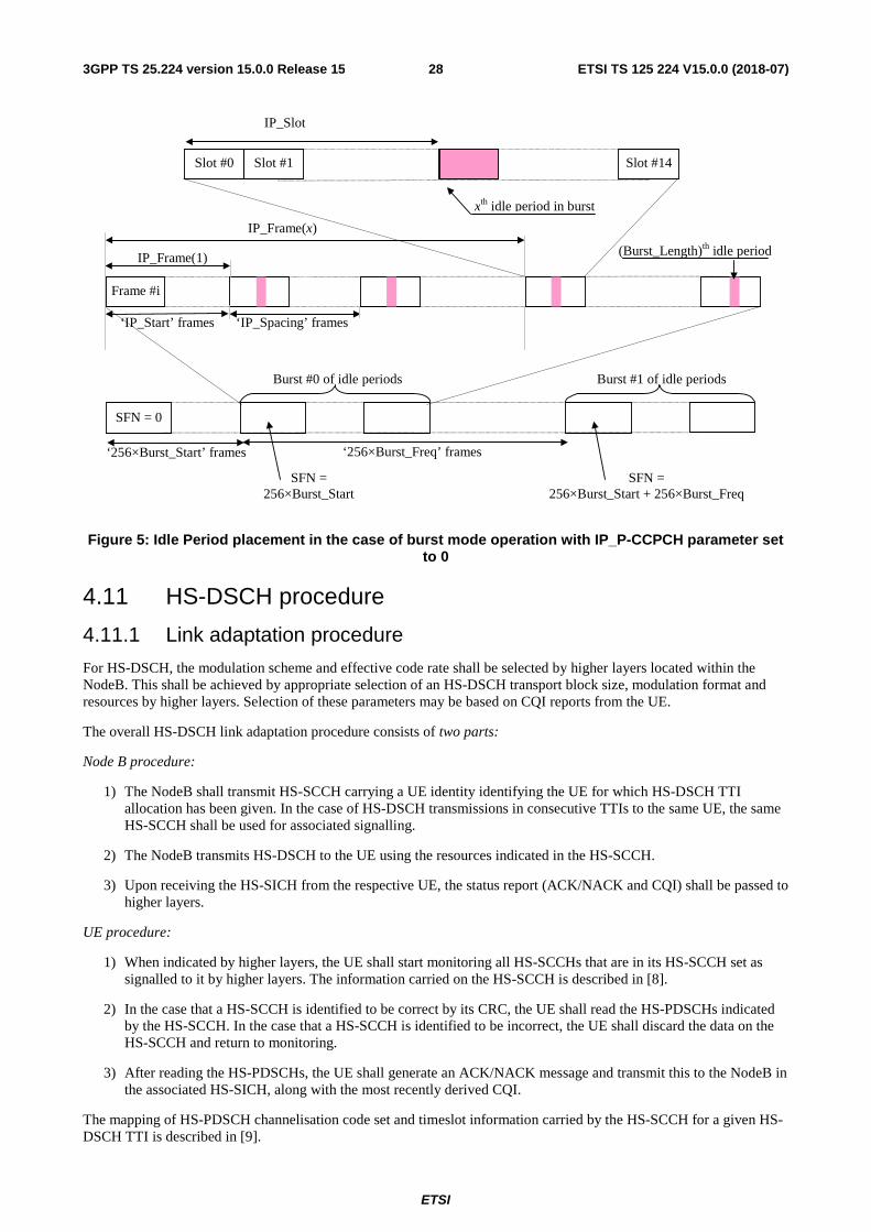
ETSI
ETSI TS 125 224 V15.0.0 (2018-07)283GPP TS 25.224 version 15.0.0 Release 15
Figure 5: Idle Period placement in the case of burst mode operation with IP_P-CCPCH parameter set to 0
4.11 HS-DSCH procedure
4.11.1 Link adaptation procedure
For HS-DSCH, the modulation scheme and effective code rate shall be selected by higher layers located within the NodeB. This shall be achieved by appropriate selection of an HS-DSCH transport block size, modulation format and resources by higher layers. Selection of these parameters may be based on CQI reports from the UE.
The overall HS-DSCH link adaptation procedure consists of two parts:
Node B procedure:
1) The NodeB shall transmit HS-SCCH carrying a UE identity identifying the UE for which HS-DSCH TTI allocation has been given. In the case of HS-DSCH transmissions in consecutive TTIs to the same UE, the same HS-SCCH shall be used for associated signalling.
2) The NodeB transmits HS-DSCH to the UE using the resources indicated in the HS-SCCH.
3) Upon receiving the HS-SICH from the respective UE, the status report (ACK/NACK and CQI) shall be passed to higher layers.
UE procedure:
1) When indicated by higher layers, the UE shall start monitoring all HS-SCCHs that are in its HS-SCCH set as signalled to it by higher layers. The information carried on the HS-SCCH is described in [8].
2) In the case that a HS-SCCH is identified to be correct by its CRC, the UE shall read the HS-PDSCHs indicated by the HS-SCCH. In the case that a HS-SCCH is identified to be incorrect, the UE shall discard the data on the HS-SCCH and return to monitoring.
3) After reading the HS-PDSCHs, the UE shall generate an ACK/NACK message and transmit this to the NodeB in the associated HS-SICH, along with the most recently derived CQI.
The mapping of HS-PDSCH channelisation code set and timeslot information carried by the HS-SCCH for a given HS-DSCH TTI is described in [9].
(Burst_Length)th idle period
IP_Frame(x)
IP_Frame(1)
‘256×Burst_Freq’ frames
Burst #0 of idle periods
Frame #i
SFN = 0
‘IP_Start’ frames
‘256×Burst_Start’ frames
Burst #1 of idle periods
‘IP_Spacing’ frames
Slot #0 Slot #1 Slot #14
SFN = 256×Burst_Start
SFN = 256×Burst_Start + 256×Burst_Freq
IP_Slot
xth idle period in burst
ETSI
ETSI TS 125 224 V15.0.0 (2018-07)293GPP TS 25.224 version 15.0.0 Release 15
For a given allocation of HS-PDSCH resources to a UE for a specific HS-DSCH TTI, the following shall apply:
- If timeslot information on HS-SCCH indicates two or more timeslots, none of these timeslots shall comprise a beacon channel.
- If timeslot information on HS-SCCH indicates a single timeslot and this timeslot comprises a beacon channel then:
- The Node-B shall not indicate SF=1 for any HS-PDSCH resource.
- The set of HS-PDSCH resources allocated by the Node-B to a UE shall exclusively comprise either beacon function or non-beacon function physical channels. The Node B shall therefore not allocate both beacon function and non-beacon function physical channels within the beacon timeslot to the UE. If the HS-DSCH for a specific HS-DSCH TTI is mapped to the beacon channel, this shall be signalled using kstart = 1 and kstop = 1. For a definition of the first and last allocated channelisation code indices kstart and kstop on HS-SCCH refer to [9].
- When SCTD antenna diversity is applied to the beacon channel, then the presence of channelisation code )1(
16C within the channelisation code set information on HS-SCCH shall implicitly indicate the presence of
channelisation code )2(16C .
4.11.2 HS-DSCH channel quality indication procedure
The channel quality indicator (CQI) provides the NodeB with an estimate of the code rate that would have maximised the single-transmission throughput of the previous HS-DSCH transmission if decoded in isolation. The CQI report requires to be referenced to a given set of HS-PDSCH resources by the NodeB, but note that the UE is not restricted to making measurements only on these reference resources when deriving a given CQI. The reference resources for a CQI report shall be a set of HS-PDSCH resources that were received by the UE in a single TTI, and contain a complete transport block. These resources will be known to the NodeB from the relative timings of the HS-SICH carrying the CQI and previous HS-DSCH transmissions to the UE.
The CQI consists of two fields; a Recommended Transport Block Size (RTBS) and a Recommended Modulation Format (RMF). The UE shall use the same mapping table for these fields as is being used for the time slot information and modulation scheme information fields respectively of the HS-SCCH [18].
The reporting procedure is as follows:
1. The UE receives a message on an HS-SCCH telling it which resources have been allocated to it for the next associated HS-DSCH transmission.
2. The UE reads the associated HS-DSCH transmission, and makes the necessary measurements to derive a CQI that it estimates would have given it the highest single-transmission throughput for the allocated resources whilst achieving a BLER of no more than 10 %.
BLER, in this context, is defined as the probability that a transport block transmitted using the RTBS and RMF is received in error if decoded in isolation. For the purposes of this calculation, it shall be assumed that the transport block that would be transmitted with these parameters would use redundancy version parameters s = 1 and r = 0. Note that, by this definition, a UE shall never report a CQI that corresponds to a code rate greater than unity.
Using this definition of BLER, single-transmission throughput shall be defined as follows :
single-transmission throughput = (1 – BLER) × RTBS
3, The CQI report derived from a given HS-DSCH transmission shall be reported to the NodeB in the next HS-SICH available to the UE following that HS-DSCH transmission, unless that HS-SICH immediately follows the last allocated HS-DSCH timeslot, in which case the subsequent available HS-SICH shall be used by the UE. This HS-SICH may not necessarily be the same HS-SICH that carries the ACK/NACK information for that HS-DSCH transmission. The UE shall always transmit the most recently derived CQI in any given HS-SICH, which may mean that some CQI reports are discarded without being transmitted to the NodeB.
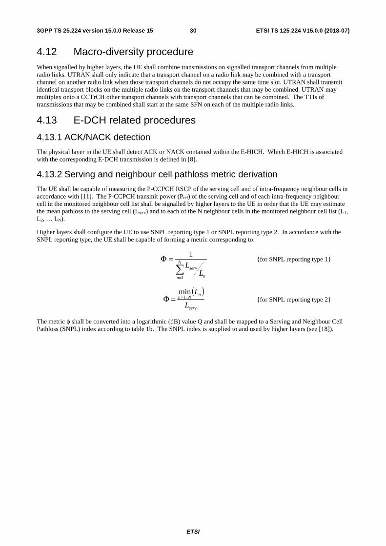
ETSI
ETSI TS 125 224 V15.0.0 (2018-07)303GPP TS 25.224 version 15.0.0 Release 15
4.12 Macro-diversity procedure When signalled by higher layers, the UE shall combine transmissions on signalled transport channels from multiple radio links. UTRAN shall only indicate that a transport channel on a radio link may be combined with a transport channel on another radio link when those transport channels do not occupy the same time slot. UTRAN shall transmit identical transport blocks on the multiple radio links on the transport channels that may be combined. UTRAN may multiplex onto a CCTrCH other transport channels with transport channels that can be combined. The TTIs of transmissions that may be combined shall start at the same SFN on each of the multiple radio links.
4.13 E-DCH related procedures
4.13.1 ACK/NACK detection
The physical layer in the UE shall detect ACK or NACK contained within the E-HICH. Which E-HICH is associated with the corresponding E-DCH transmission is defined in [8].
4.13.2 Serving and neighbour cell pathloss metric derivation
The UE shall be capable of measuring the P-CCPCH RSCP of the serving cell and of intra-frequency neighbour cells in accordance with [11]. The P-CCPCH transmit power (Pref) of the serving cell and of each intra-frequency neighbour cell in the monitored neighbour cell list shall be signalled by higher layers to the UE in order that the UE may estimate the mean pathloss to the serving cell (Lserv) and to each of the N neighbour cells in the monitored neighbour cell list (L1, L2, … LN).
Higher layers shall configure the UE to use SNPL reporting type 1 or SNPL reporting type 2. In accordance with the SNPL reporting type, the UE shall be capable of forming a metric corresponding to:
=
=Φ N
n n
servL
L
1
1 {for SNPL reporting type 1}
( )
serv
nNn
L
L..1
min==Φ {for SNPL reporting type 2}
The metric φ shall be converted into a logarithmic (dB) value Q and shall be mapped to a Serving and Neighbour Cell Pathloss (SNPL) index according to table 1b. The SNPL index is supplied to and used by higher layers (see [18]).
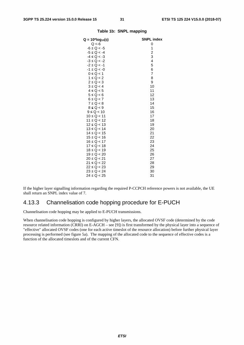
ETSI
ETSI TS 125 224 V15.0.0 (2018-07)313GPP TS 25.224 version 15.0.0 Release 15
Table 1b: SNPL mapping
Q = 10*log10(φ) SNPL index Q <-6 0
-6 ≤ Q < -5 1 -5 ≤ Q < -4 2 -4 ≤ Q < -3 3 -3 ≤ Q < -2 4 -2 ≤ Q < -1 5 -1 ≤ Q < -0 6 0 ≤ Q < 1 7 1 ≤ Q < 2 8 2 ≤ Q < 3 9 3 ≤ Q < 4 10 4 ≤ Q < 5 11 5 ≤ Q < 6 12 6 ≤ Q < 7 13 7 ≤ Q < 8 14 8 ≤ Q < 9 15
9 ≤ Q < 10 16 10 ≤ Q < 11 17 11 ≤ Q < 12 18 12 ≤ Q < 13 19 13 ≤ Q < 14 20 14 ≤ Q < 15 21 15 ≤ Q < 16 22 16 ≤ Q < 17 23 17 ≤ Q < 18 24 18 ≤ Q < 19 25 19 ≤ Q < 20 26 20 ≤ Q < 21 27 21 ≤ Q < 22 28 22 ≤ Q < 23 29 23 ≤ Q < 24 30 24 ≤ Q < 25 31
If the higher layer signalling information regarding the required P-CCPCH reference powers is not available, the UE shall return an SNPL index value of 7.
4.13.3 Channelisation code hopping procedure for E-PUCH
Channelisation code hopping may be applied to E-PUCH transmissions.
When channelisation code hopping is configured by higher layers, the allocated OVSF code (determined by the code resource related information (CRRI) on E-AGCH – see [9]) is first transformed by the physical layer into a sequence of "effective" allocated OVSF codes (one for each active timeslot of the resource allocation) before further physical layer processing is performed (see figure 5a). The mapping of the allocated code to the sequence of effective codes is a function of the allocated timeslots and of the current CFN.
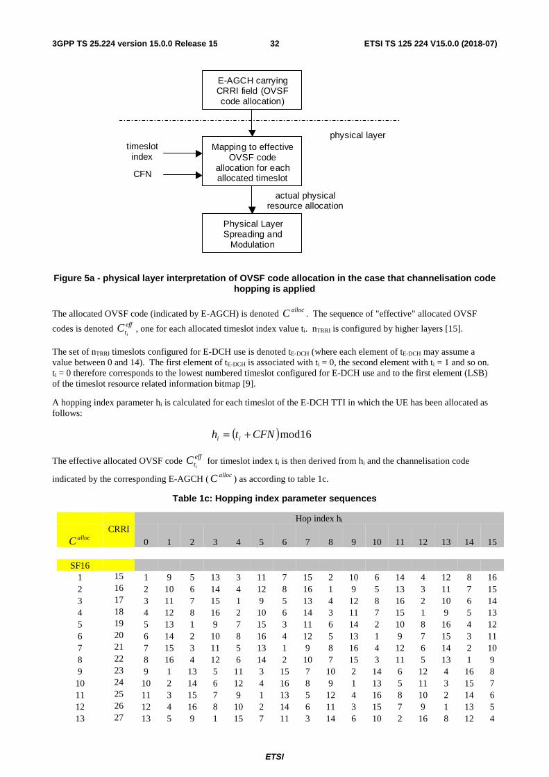
ETSI
ETSI TS 125 224 V15.0.0 (2018-07)323GPP TS 25.224 version 15.0.0 Release 15
E-AGCH carrying CRRI field (OVSF code allocation)
Mapping to effective OVSF code
allocation for each allocated timeslot
timeslot index
CFN
actual physical resource allocation
physical layer
Physical Layer Spreading and
Modulation
Figure 5a - physical layer interpretation of OVSF code allocation in the case that channelisation code hopping is applied
The allocated OVSF code (indicated by E-AGCH) is denoted allocC . The sequence of "effective" allocated OVSF
codes is denoted effti
C , one for each allocated timeslot index value ti. nTRRI is configured by higher layers [15].
The set of nTRRI timeslots configured for E-DCH use is denoted tE-DCH (where each element of tE-DCH may assume a value between 0 and 14). The first element of tE-DCH is associated with ti = 0, the second element with ti = 1 and so on. ti = 0 therefore corresponds to the lowest numbered timeslot configured for E-DCH use and to the first element (LSB) of the timeslot resource related information bitmap [9].
A hopping index parameter hi is calculated for each timeslot of the E-DCH TTI in which the UE has been allocated as follows:
( ) 16modCFNth ii +=
The effective allocated OVSF code effti
C for timeslot index ti is then derived from hi and the channelisation code
indicated by the corresponding E-AGCH ( allocC ) as according to table 1c.
Table 1c: Hopping index parameter sequences
Hop index hi
allocC
CRRI
0 1 2 3 4 5 6 7 8 9 10 11 12 13 14 15
SF16 1 15 1 9 5 13 3 11 7 15 2 10 6 14 4 12 8 16 2 16 2 10 6 14 4 12 8 16 1 9 5 13 3 11 7 15 3 17 3 11 7 15 1 9 5 13 4 12 8 16 2 10 6 14 4 18 4 12 8 16 2 10 6 14 3 11 7 15 1 9 5 13 5 19 5 13 1 9 7 15 3 11 6 14 2 10 8 16 4 12 6 20 6 14 2 10 8 16 4 12 5 13 1 9 7 15 3 11 7 21 7 15 3 11 5 13 1 9 8 16 4 12 6 14 2 10 8 22 8 16 4 12 6 14 2 10 7 15 3 11 5 13 1 9 9 23 9 1 13 5 11 3 15 7 10 2 14 6 12 4 16 8 10 24 10 2 14 6 12 4 16 8 9 1 13 5 11 3 15 7 11 25 11 3 15 7 9 1 13 5 12 4 16 8 10 2 14 6 12 26 12 4 16 8 10 2 14 6 11 3 15 7 9 1 13 5 13 27 13 5 9 1 15 7 11 3 14 6 10 2 16 8 12 4
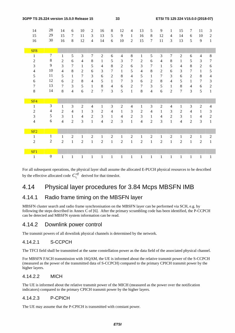
ETSI
ETSI TS 125 224 V15.0.0 (2018-07)333GPP TS 25.224 version 15.0.0 Release 15
14 28 14 6 10 2 16 8 12 4 13 5 9 1 15 7 11 3 15 29 15 7 11 3 13 5 9 1 16 8 12 4 14 6 10 2 16 30 16 8 12 4 14 6 10 2 15 7 11 3 13 5 9 1
SF8 1 7 1 5 3 7 2 6 4 8 1 5 3 7 2 6 4 8 2 8 2 6 4 8 1 5 3 7 2 6 4 8 1 5 3 7 3 9 3 7 1 5 4 8 2 6 3 7 1 5 4 8 2 6 4 10 4 8 2 6 3 7 1 5 4 8 2 6 3 7 1 5 5 11 5 1 7 3 6 2 8 4 5 1 7 3 6 2 8 4 6 12 6 2 8 4 5 1 7 3 6 2 8 4 5 1 7 3 7 13 7 3 5 1 8 4 6 2 7 3 5 1 8 4 6 2 8 14 8 4 6 2 7 3 5 1 8 4 6 2 7 3 5 1
SF4 1 3 1 3 2 4 1 3 2 4 1 3 2 4 1 3 2 4 2 4 2 4 1 3 2 4 1 3 2 4 1 3 2 4 1 3 3 5 3 1 4 2 3 1 4 2 3 1 4 2 3 1 4 2 4 6 4 2 3 1 4 2 3 1 4 2 3 1 4 2 3 1
SF2 1 1 1 2 1 2 1 2 1 2 1 2 1 2 1 2 1 2 2 2 2 1 2 1 2 1 2 1 2 1 2 1 2 1 2 1
SF1 1 0 1 1 1 1 1 1 1 1 1 1 1 1 1 1 1 1
For all subsequent operations, the physical layer shall assume the allocated E-PUCH physical resources to be described
by the effective allocated code effti
C derived for that timeslot.
4.14 Physical layer procedures for 3.84 Mcps MBSFN IMB
4.14.1 Radio frame timing on the MBSFN layer
MBSFN cluster search and radio frame synchronisation on the MBSFN layer can be performed via SCH, e.g. by following the steps described in Annex C of [6]. After the primary scrambling code has been identified, the P-CCPCH can be detected and MBSFN system information can be read.
4.14.2 Downlink power control
The transmit powers of all downlink physical channels is determined by the network.
4.14.2.1 S-CCPCH
The TFCI field shall be transmitted at the same constellation power as the data field of the associated physical channel.
For MBSFN FACH transmission with 16QAM, the UE is informed about the relative transmit power of the S-CCPCH (measured as the power of the transmitted data of S-CCPCH) compared to the primary CPICH transmit power by the higher layers.
4.14.2.2 MICH
The UE is informed about the relative transmit power of the MICH (measured as the power over the notification indicators) compared to the primary CPICH transmit power by the higher layers.
4.14.2.3 P-CPICH
The UE may assume that the P-CPICH is transmitted with constant power.
ETSI
ETSI TS 125 224 V15.0.0 (2018-07)343GPP TS 25.224 version 15.0.0 Release 15
4.14.2.4 T-CPICH
The UE may assume that each constituent OVSF code of the T-CPICH is transmitted with equal power. The UE may also assume the ratio of power allocated to the T-CPICH and P-CPICH is constant.
5 Physical layer procedures for the 1.28 Mcps option
5.1 Transmitter power control The basic purpose of power control is to limit the interference level within the system thus reducing the intercell interference level and to reduce the power consumption in the UE.
The main characteristics of power control are summarized in the following table.
Table 2: Transmit Power Control characteristics
Uplink Downlink
Power control rate Variable Closed loop: 0-200 cycles/sec. Open loop: (about 200us – 3575us delay )
Variable Closed loop: 0-200 cycles/sec.
Step size 1,2,3 dB (closed loop) 1,2,3 dB (closed loop)
Remarks All figures are without processing and measurement times
Note: All codes within one timeslot allocated to the same CCTrCH use the same transmission power in case they have the same Spreading Factor.
5.1.1 Uplink control
5.1.1.1 General limits
By means of higher layer signalling, the Maximum_Allowed_UL_TX_ power for uplink may be set to a value lower than what the terminal power class is capable of. Uplink power control shall be performed while the total UE transmit power is below the maximum allowed output TX power. In some cases the total requested UE transmit power in a timeslot after uplink power control calculation might exceed the maximum allowed output power. In these cases the calculated transmit power of all uplink physical channels in this timeslot shall be scaled by the same amount in dB before transmission in order that the total UE transmission power used shall be the maximum allowed output power.
The UTRAN may not expect the UE to be capable of reducing its total transmit power below the minimum level specified in [2].
5.1.1.2 UpPCH
The transmit power for the UpPCH is set by higher layers based on open loop power control as described in [15]
5.1.1.3 PRACH
The transmit power for the PRACH is set by higher layers based on open loop power control as described in [15].
5.1.1.4 DPCH and PUSCH
The initial transmission power for uplink DPCH and PUSCH is set by higher layers based on open loop power control as described in [15]. The UE then transits into closed loop power control. The node B shall generate TPC commands
ETSI
ETSI TS 125 224 V15.0.0 (2018-07)353GPP TS 25.224 version 15.0.0 Release 15
according to a quality target set by higher layers in order to instruct an increase or decrease in the level of transmission power from the UE and send them either in the TPC field of associated downlink CCTrCHs (see [8] for a description of the mapping between DL associated TPC symbols and UL controlled CCTrCH/timeslots) or on PLCCH (see [8] 5A.3.13). If the physical channel power should be increased, the TPC command is set to "up", whereas if the power should be reduced the command is set to "down". A TPC command sent in a downlink CCTrCH or via PLCCH controls all uplink DPCHs and PUSCHs in the associated uplink CCTrCH and timeslot. An example of SIR based UL power control is given in annex A2
If signalled by higher layers, the UE must follow the received TPC commands only. In this case, at the UE when the TPC command is judged as 'down', the mobile transmit power shall be reduced by one power control step, whereas if it is judged as 'up', the mobile transmit power shall be raised by one power control step.
If indicated as allowed by higher layers, the UE may optionally take into account pathloss estimated from beacon function physical channels in addition to the TPC commands when calculating the transmit power. In this case, the mobile transmit power is first modified as described above by the received TPC command and is then further modified based upon the pathloss estimated on recent beacon transmissions. Modifications based upon pathloss shall only be applied when the UE estimates that the pathloss on the uplink transmission timeslot and the pathloss on the beacon timeslots used to derive the modification value are likely to be similar.
The closed loop power control procedure for UL DPCH and PUSCH is not affected by the use of TSTD.
In the event of no associated uplink data being transmitted between two related downlink TPC commands, the UE shall ignore the resulting TPC command. The transmit power for the next instance of the timeslot/CCTrCH pair shall then be set:
i) to the power level of the previous uplink transmission, optionally modified to compensate for the change in pathloss observed during the uplink transmission pause or,
ii) using the open loop procedure as for initial transmissions.
The UE shall select which of the above methods to apply. For short transmission pauses method (i) should be used.
5.1.1.4.1 Gain factors
Same as that of 3.84 Mcps TDD, cf. [4.2.2.3.1 Gain factors].
5.1.1.4.2 Out of synchronization handling
In the case that uplink DPCH is controlled by TPC commands carried on downlink DPCH, out of synchronisation handling is the same as that of 3.84 Mcps TDD, cf.[ 4.2.2.3.2 Out of synchronisation handling].
In the case that uplink DPCH is controlled by TPC commands carried on PLCCH, the UE shall shut off the transmission of an UL CCTrCH if the following criteria are fulfilled for the PLCCH carrying its TPC commands:
- The UE estimates the received PLCCH quality over the last 160 ms period to be worse than a threshold Qout. Qout is defined implicitly by the relevant tests in [2].
The UE shall subsequently resume the uplink transmission of the CCTrCH if the following criteria are fulfilled:
- The UE estimates the received PLCCH reception quality over the last 160 ms period to be better than a threshold Qin. Qin is defined implicitly by the relevant tests in [2].
5.1.1.5 HS-SICH
If the UE is not configured in MIMO mode, the transmit power of the HS-SICH shall be set by the UE according to the procedures described below. In the case that an ACK is being transmitted on the HS-SICH, the UE shall apply a power offset to the transmit power of the entire HS-SICH. This power offset shall be signalled by higher layers.
For the transmissions on the semi-persistent HS-PDSCH resources without an HS-SCCH, the TPC command for HS-SICH can be conveyed in HS-PDSCH.
On receipt of a TPC command in the HS-SCCH or HS-PDSCH, the UE shall adjust the HS-SICH transmit power according to the power control step size specified by higher layers. The UE shall ignore the TPC command transmitted
ETSI
ETSI TS 125 224 V15.0.0 (2018-07)363GPP TS 25.224 version 15.0.0 Release 15
on an HS-SCCH order which is an uplink synchronization establishment command. An example of SIR based UL power control is given in annex A5.
i) However, for the first HS-SICH transmission following the first detected HS-SCCH transmission, the UE shall use open loop power control to set the HS-SICH transmit power for that transmission. In this case, the transmission power for HS-SICH is set by higher layers based on open loop power control as described in [15].
ii) When the transmission interval of HS-SICHs, which are in the same time slot, is less than a certain threshold, which is signalled by higher layers, UE shall adjust the transmit power according to received TPC command in HS-SCCH or HS-PDSCH during HS-SICH transmission pause based on transmission power of last instance. When receipt of TPC commands in HS-PDSCH and in HS-SCCH is in the same sub-frame, UE shall treat one single TPC command if they are identical and discard them if they are different. If indicated by higher layers, UE should take into account the pathloss compensation by means of beacon channel estimation in addition to the TPC command when calculating HS-SICH transmit power.
iii) When the transmission interval of HS-SICHs, which are in the same time slot, is equal or larger than a certain threshold, for the next instance of HS-SICH, UE shall use open loop power control described above for the initial transmission.
If the UE is configured in MIMO mode, the transmit power of the HS-SICH shall be set by the UE according to the procedures described below.
The procedure for MIMO single stream transmission is the same as that the UE is not configured in MIMO mode.
For MIMO dual stream transmission, in the case that two ACKs are being transmitted on the HS-SICH, the UE shall apply a power offset to the transmit power of the entire HS-SICH. This power offset shall be signalled by higher layers.
On receipt of a TPC command in the HS-SCCH or HS-PDSCH, the UE shall adjust the HS-SICH transmit power according to the power control step size specified by higher layers. An example of SIR based UL power control is given in annex A5.
i) However, for the first HS-SICH transmission following the first detected HS-SCCH transmission, the UE shall use open loop power control to set the HS-SICH transmit power for that transmission. In the case of dual stream transmission, a delta is applied to the HS-SICH transmission power. The delta implies the required power offset of the HS-SICH transmission for the different number of the data streams under the limit of SIR target. This transmission power is set by higher layers based on open loop power control as described in [15].
ii) When the transmission interval of HS-SICHs, which are in the same time slot, is less than a certain threshold,which is signalled by higher layers, UE shall adjust the transmit power according to received TPC command during HS-SICH transmission pause based on transmission power of last instance. In the case of dual stream transmission, a delta is applied to the HS-SICH transmission power. If indicated by higher layers, UE should take into account the pathloss compensation by means of beacon channel estimation in addition to the TPC command when calculating HS-SICH transmit power.
iii) When the transmission interval of HS-SICHs, which are in the same time slot, is equal or larger than a certain threshold, for the next instance of HS-SICH, UE shall use open loop power control described above for the initial transmission.
5.1.1.6 E-PUCH
For multi-carrier E-DCH transmission, the open-loop and closed-loop power control of E-PUCH on each carrier is independent from each other. The power of E-PUCH in each timeslot on each carrier is set as follows. Note that the power of E-PUCH in the timeslots with same spreading factor is the same.
The power of E-PUCH in each timeslot is set following the same principle used for DPCH/PUSCH in R4/5/6[15] and in 5.1.1.4, i.e., the combination of open-loop power control and traditional closed-loop power control:
- the initial transmit power of E-PUCH is set based on an open-loop power control scheme, then
- the transmission power control transits into closed-loop power control using TPC commands carried on E-AGCH or on E-HICH on the same carrier. For non-scheduled transmission, the TPC commands are carried on E-HICH only. Both TPC commands carried on E-AGCH and E-HICH are used on E-PUCH
The transmit power for E-PUCH set in each timeslot is calculated as follows:
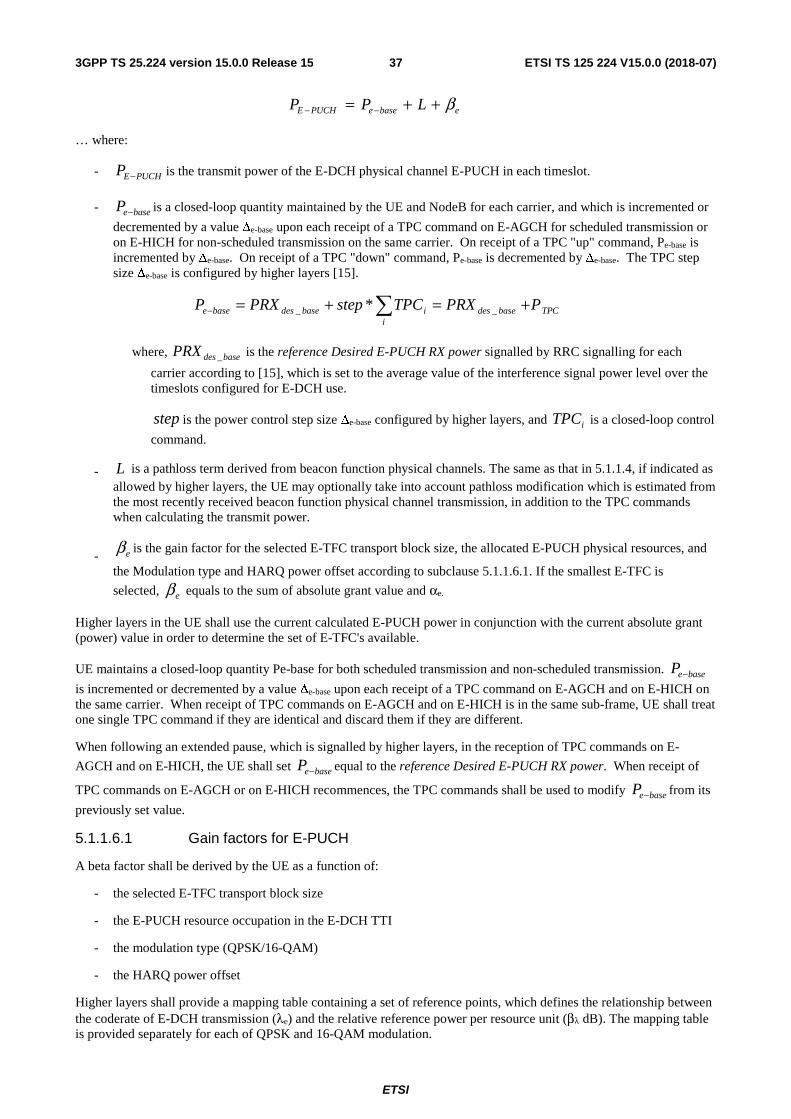
ETSI
ETSI TS 125 224 V15.0.0 (2018-07)373GPP TS 25.224 version 15.0.0 Release 15
ebaseePUCHE LPP β++= −−
… where:
- is the transmit power of the E-DCH physical channel E-PUCH in each timeslot.
- is a closed-loop quantity maintained by the UE and NodeB for each carrier, and which is incremented or
decremented by a value Δe-base upon each receipt of a TPC command on E-AGCH for scheduled transmission or on E-HICH for non-scheduled transmission on the same carrier. On receipt of a TPC "up" command, Pe-base is incremented by Δe-base. On receipt of a TPC "down" command, Pe-base is decremented by Δe-base. The TPC step size Δe-base is configured by higher layers [15].
where, is the reference Desired E-PUCH RX power signalled by RRC signalling for each
carrier according to [15], which is set to the average value of the interference signal power level over the timeslots configured for E-DCH use.
is the power control step size Δe-base configured by higher layers, and is a closed-loop control
command.
- is a pathloss term derived from beacon function physical channels. The same as that in 5.1.1.4, if indicated as allowed by higher layers, the UE may optionally take into account pathloss modification which is estimated from the most recently received beacon function physical channel transmission, in addition to the TPC commands when calculating the transmit power.
- is the gain factor for the selected E-TFC transport block size, the allocated E-PUCH physical resources, and
the Modulation type and HARQ power offset according to subclause 5.1.1.6.1. If the smallest E-TFC is
selected, equals to the sum of absolute grant value and αe.
Higher layers in the UE shall use the current calculated E-PUCH power in conjunction with the current absolute grant (power) value in order to determine the set of E-TFC's available.
UE maintains a closed-loop quantity Pe-base for both scheduled transmission and non-scheduled transmission.
is incremented or decremented by a value Δe-base upon each receipt of a TPC command on E-AGCH and on E-HICH on the same carrier. When receipt of TPC commands on E-AGCH and on E-HICH is in the same sub-frame, UE shall treat one single TPC command if they are identical and discard them if they are different.
When following an extended pause, which is signalled by higher layers, in the reception of TPC commands on E-
AGCH and on E-HICH, the UE shall set equal to the reference Desired E-PUCH RX power. When receipt of
TPC commands on E-AGCH or on E-HICH recommences, the TPC commands shall be used to modify from its
previously set value.
5.1.1.6.1 Gain factors for E-PUCH
A beta factor shall be derived by the UE as a function of:
- the selected E-TFC transport block size
- the E-PUCH resource occupation in the E-DCH TTI
- the modulation type (QPSK/16-QAM)
- the HARQ power offset
Higher layers shall provide a mapping table containing a set of reference points, which defines the relationship between the coderate of E-DCH transmission (λe) and the relative reference power per resource unit (βλ dB). The mapping table is provided separately for each of QPSK and 16-QAM modulation.
PUCHEP −
baseeP −
TPCbasedesi
ibasedesbasee PPRXTPCstepPRXP +=+= − __ *
basedesPRX _
step iTPC
L
eβ
eβ
baseeP −
baseeP −
baseeP −
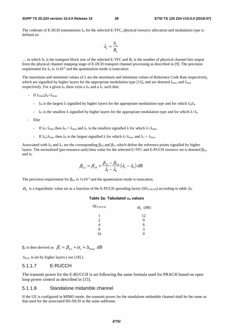
ETSI
ETSI TS 125 224 V15.0.0 (2018-07)383GPP TS 25.224 version 15.0.0 Release 15
The coderate of E-DCH transmission λe for the selected E-TFC, physical resource allocation and modulation type is defined as:
e
ee R
S=λ
… in which Se is the transport block size of the selected E-TFC and Re is the number of physical channel bits output from the physical channel mapping stage of E-DCH transport channel processing as described in [9]. The precision requirement for λe is 1x10⁻⁴ and the quantization mode is truncation.
The maximum and minimum values of λ are the maximum and minimum values of Reference Code Rate respectively, which are signalled by higher layers for the appropriate modulation type [15], and are denoted λmax and λmin respectively. For a given λe there exist a λ0 and a λ1 such that:
- If λmin≤λe<λmax
- λ0 is the largest λ signalled by higher layers for the appropriate modulation type and for which λ≤λe
- λ1 is the smallest λ signalled by higher layers for the appropriate modulation type and for which λ>λe
- Else
- If λe<λmin then λ0 = λmin and λ1 is the smallest signalled λ for which λ>λmin.
- If λe≥λmax then λ0 is the largest signalled λ for which λ<λmax and λ1 = λmax
Associated with λ0 and λ1 are the corresponding βλ0 and βλ1 which define the reference points signalled by higher layers. The normalised (per-resource-unit) beta value for the selected E-TFC and E-PUCH resource set is denoted β0,e and is:
( ) dBee 001
010,0 λλ
λλββββ λλ
λ −−−+=
The precision requirement for β0,e is 1x10⁻³ and the quantization mode is truncation.
eα is a logarithmic value set as a function of the E-PUCH spreading factor (SFE-PUCH) according to table 2a.
Table 2a: Tabulated αe values
SFE-PUCH eα (dB)
1 12 2 9 4 6 8 3 16 0
βe is then derived as dBharqeee Δ++= αββ ,0
Δharq is set by higher layers ( see [18] ).
5.1.1.7 E-RUCCH
The transmit power for the E-RUCCH is set following the same formula used for PRACH based on open loop power control as described in [15].
5.1.1.8 Standalone midamble channel
If the UE is configured in MIMO mode, the transmit power for the standalone midamble channel shall be the same as that used for the associated HS-SICH in the same subframe.
ETSI
ETSI TS 125 224 V15.0.0 (2018-07)393GPP TS 25.224 version 15.0.0 Release 15
If the UE is configured in MU-MIMO mode, the transmit power for the standalone midamble channel shall make reference to the last transmitted HS-SICH or E-PUCH. When the last transmitted uplink channel is HS-SICH, the transmit power of the standalone midamble channel shall be the same as the last transmitted HS-SICH.When the last transmitted uplink channel is E-PUCH, the transmit power of the standalone midamble channel shall be calculated as follows:
SbaseedaloneS LPP β++= −tan
… where:
- baseeP − is the desired receiving power of E-PUCH.
- Sβ is the gain factor for standalone midamble channel, and should be configured by high layer.
- is a pathloss term derived from beacon function physical channels.
5.1.2 Downlink control
The total downlink transmission power at the Node B within one timeslot shall not exceed the Maximum Transmission Power set by higher layer signalling.
5.1.2.1 P-CCPCH
Same as that of 3.84 Mcps TDD, cf.[4.2.3.1 P-CCPCH].
5.1.2.2 The power of the FPACH
The transmit power for the FPACH is set by the higher layer signalling [16].
5.1.2.3 S-CCPCH, PICH
Same as that of 3.84 Mcps TDD, cf.[4.2.3.2 S-CCPCH , PICH].
5.1.2.3A MICH
Same as that of 3.84 Mcps TDD, cf.[4.2.3.2A MICH].
5.1.2.4 DPCH, PDSCH
The initial transmission power of the downlink Dedicated Physical Channel is signalled by higher layers. After the initial transmission, the node B transits into closed-loop TPC. The UE shall generate TPC commands according to a quality target set by higher layers in order to control the level of transmission power from the node B and send them in the TPC field of associated uplink CCTrCHs (see [8] for a description of the mapping between UL associated TPC symbols and DL controlled CCTrCH/timeslots) or in the Non-scheduled E-PUCH when the associated uplink CCTrCHs do not exist. If the physical channel power should be increased, the TPC command is set to "up", whereas if the power should be reduced the command is set to "down". A TPC command sent in an uplink CCTrCH or in the Non-scheduled E-PUCH when the associated uplink CCTrCH does not exist controls all downlink DPCHs or PDSCHs in the associated downlink CCTrCH and timeslot.
UTRAN may decide how to adjust the transmit power in response to the received TPC command
When TSTD is applied, the UE can use two consecutive measurements of the received SIR in two consecutive sub-frames to generate the power control command. An example implementation of DL power control procedure for 1.28 Mcps TDD when TSTD is applied is given in Annex A.3.
The transmission power of one DPCH or PDSCH shall not exceed the limits set by higher layer signalling by means of Maximum_DL_Power (dB) and Minimum_DL_Power (dB). The transmission power is defined as the average power over one timeslot of the complex QPSK (or 8PSK respectively) symbols of a single DPCH or PDSCH before spreading relative to the power of the P-CCPCH.
Each TPC command shall be based on all associated downlink transmissions since the previous related TPC command.
L
ETSI
ETSI TS 125 224 V15.0.0 (2018-07)403GPP TS 25.224 version 15.0.0 Release 15
In the event of no associated downlink data being transmitted between two related TPC commands, the UTRAN should ignore the resulting TPC command.
5.1.2.4.1 Out of synchronisation handling
Same as that of 3.84 Mcps TDD, cf.[4.2.3.4.1 Out of synchronisation handling].
5.1.2.5 HS-PDSCH
The power control for HS-PDSCH for 1.28 Mcps TDD is the same as for 3.84 Mcps, see section 4.2.3.5
5.1.2.6 HS-SCCH
Higher layers shall indicate the maximum transmit power of the HS-SCCH. The Node-B shall not exceed this maximum power when setting the HS-SCCH power.
The initial power of the HS-SCCH is at the discretion of the Node-B. Following the initial transmission, the NodeB may optionally power control the HS-SCCH. This may be done using TPC commands sent by the UE in the HS-SICH. When the transmission interval of HS-SCCHs, which are in the same time slot, is more than or equal to a certain threshold, which is signalled by higher layers, NodeB shall use initial transmit power for the next HS-SCCH transmission.
The UE shall set the TPC commands in the HS-SICH in order to control the transmit power of the HS-SCCH. The TPC commands shall be set in order to meet the HS-SCCH target BLER.
The accuracy of the received HS-SCCH BLER estimate made by the UE may be enhanced by a suitable use of the HCSN field received within the HS-SCCH itself [9]. This field shall initially be set to zero and shall be incremented by the NodeB each time an HS-SCCH is transmitted to the UE. UE without a dedicated UE identity in CELL_FACH state and UE in CELL_PCH state shall ignore the value of HCSN.
5.1.2.7 PLCCH
The initial transmission power of the downlink PLCCH is signalled by higher layers. After the initial transmission, the transmission power of PLCCH is under the control of Node-B. The Node-B may optionally adjust the transmission power of PLCCH according to the received TPC commands which are carried by the PLCCH-controlled UL CCTrCH(s). The UE shall generate TPC commands according to a PLCCH quality target set by higher layers. If the PLCCH power should be increased, the TPC command is set to "up", whereas if the power should be reduced the command is set to "down". UTRAN may decide how to adjust the transmit power in response to the received TPC commands. The average power of transmitted PLCCH symbols over one timeslot shall not exceed the limits set by higher layers. The transmission power is defined as the average power over one timeslot of the complex QPSK symbols of a single PLCCH before spreading relative to the power of the P-CCPCH.
5.1.2.8 E-AGCH
For multi-carrier E-DCH transmission, the power control of E-AGCH on each carrier is independent from each other and described as follows.
Higher layers shall indicate the maximum transmit power of the E-AGCH. The Node-B shall not exceed this maximum power when setting the E-AGCH power.
The initial power of the E-AGCH is at the discretion of the Node-B. Following the initial transmission, the NodeB may optionally power control the E-AGCH. This may be done using TPC commands sent by the UE in the scheduled E-PUCH on the same carrier.
The UE shall set the TPC commands in the Scheduled E-PUCH on the same carrier in order to control the transmit power of the E-AGCH. The TPC commands shall be set in order to meet the E-AGCH target BLER.
The accuracy of the received E-AGCH BLER estimate made by the UE shall be enhanced by a suitable use of the ECSN field received within the E-AGCH itself [9]. This field shall initially be set to zero and shall be incremented by the Node-B each time an E-AGCH is transmitted to the UE. For each carrier in multi-carrier E-DCH transmission, the ECSN shall initially be set to zero and shall be incremented by the Node-B each time an E-AGCH is transmitted on the carrier to the UE.
ETSI
ETSI TS 125 224 V15.0.0 (2018-07)413GPP TS 25.224 version 15.0.0 Release 15
5.1.2.9 E-HICH
The power of the E- HICH is under the control of the Node B.
5.2 UL synchronisation
5.2.1 General description
Support of UL synchronization is mandatory for the UE.
5.2.1.1 Preparation of uplink synchronization (downlink synchronization)
When a UE is powered on, it first needs to establish the downlink synchronisation with the cell. Only after the UE has established the downlink synchronisation, it shall start the uplink synchronisation procedure.
5.2.1.2 Establishment of uplink synchronization
The establishment of uplink synchronization is done during the random access procedure and involves the UpPCH and the PRACH or the E-RUCCH.
Although the UE can receive the downlink signal from the Node B, the distance to Node B is still uncertain. This would lead to unsynchronised uplink transmission. Therefore, the first transmission in the uplink direction is performed in a special time-slot UpPTS or other uplink access position indicated by UTRAN to reduce interference in the traffic time-slots.
After the detection of the SYNC-UL sequence in the searching window, the Node B will evaluate the timing, and reply by sending the adjustment information to the UE to modify its timing for next transmission. This is done with the FPACH within the following 4 sub-frames. After sending the PRACH or the E-RUCCH, the uplink synchronization is established. The uplink synchronisation procedure shall also be used for the re-establishment of the uplink synchronisation when uplink is out of synchronisation.
5.2.1.3 Maintenance of uplink synchronisation
Uplink synchronization is maintained in 1.28 Mcps TDD by sending the uplink advanced in time with respect to the timing of the received downlink.
For the maintenance of the uplink synchronization, the midamble field of each uplink burst can be used.
In each uplink time slot the midamble for each UE is different. The Node B may estimate the timing by evaluating the channel impulse response of each UE in the same time slot. Then, in the next available downlink time slot, the Node B will signal Synchronisation Shift (SS) commands to enable the UE to properly adjust its Tx timing.
5.2.2 UpPCH
Open loop uplink synchronisation control is used for UpPCH.
The UE may estimate the propagation delay Δtp based upon the path loss using the received P-CCPCH and/or DwPCH power.
The UpPCH is sent to the Node B advanced in time according to the timing of the received DwPCH. The time of the beginning of the UpPCH TTX-UpPCH is given by:
TTX-UpPCH = TRX-DwPCH -2Δtp +12*16 TC+nUpPCHShift*16Tc
nUpPCHShift =0..127,nUpPCHShift is indicated by higher layers
in multiple of 1/8 chips, where
TTX-UpPCH is the beginning time of UpPCH transmission with the UE's timing,
TRX-DwPCH is the received beginning time of DwPCH with the UE's timing,
2Δtp is the timing advance of the UpPCH default value is 48Tc.
ETSI
ETSI TS 125 224 V15.0.0 (2018-07)423GPP TS 25.224 version 15.0.0 Release 15
5.2.3 PRACH
The Node B shall measure the received SYNC-UL timing deviation UpPCHPOS. UpPCHPOS is sent in the FPACH and is represented as a 13 bit number (0-8191) being the multiple of 1/8 chips which is nearest to received position of the UpPCH.
Time of the beginning of the PRACH TTX-PRACH is given by:
TTX-PRACH = TRX-PRACH –(UpPCHADV + UpPCHPOS – 8*16 TC)
in multiple of 1/8 chips, where
TTX-PRACH is the beginning time of PRACH transmission with the UE's timing,
TRX-PRACH is the beginning time of PRACH reception with the UE's timing if the PRACH was a DL channel.
5.2.4 DPCH and PUSCH
The closed loop uplink synchronisation control uses layer 1 symbols (SS commands) for DPCH and PUSCH. After establishment of the uplink synchronisation, NodeB and UE start to use the closed loop UL synchronisation control procedure. This procedure is continuous during connected mode.
The Node B will continuously measure the timing of the UE and send the necessary synchronisation shift commands in each sub-frame. The UE shall derive a single SS command separately for each controlled uplink timeslot by combining all received SS commands that are related to the controlled time slot (cf. [8]) and that are received within the last up to M sub-frames. The value of the "Uplink synchronisation frequency" M (1..8) is configured by higher layers.
When the combined SS command is judged as 'down', the UE transmit timing for the controlled UL timeslot shall be delayed by one timing adjustment step of k/8 chips. When the command is judged as 'up', the UE transmit timing for the controlled UL timeslot shall be advanced by one timing adjustment step of k/8 chips. When the command is judged as 'do nothing', the timing shall not be changed. The value of the "Uplink synchronisation step size" k (1..8) is configured by higher layers.
The timing adjustment shall take place in each sub-frame satisfying the following equation:
0mod =′ MNSF
where
SFN' is the system frame number counting the sub-frames. The system frame number of the radio frames (SFN) can be derived from SFN' by
SFN=SFN' div 2, where div is the remainder free division operation.
During a 1.28 Mcps TDD to 1.28 Mcps TDD hand-over the UE shall transmit in the new cell with timing advance TA adjusted by the relative timing difference Δt between the new and the old cell if indicated by higher layers:
TAnew = TAold + 2Δt.
5.2.4.1 Out of synchronization handling
Same as that of 3,84 Mcps TDD, cf.[ 4.2.2.3.2 Out of synchronisation handling.]
5.2.5 HS-SICH
If there is associated uplink DPCH or non-scheduled E-PUCH, the initial transmit timing for the HS-SICH shall be taken from that of the associated uplink DPCH or non-scheduled E-PUCH. Otherwise, the initial transmit timing for the HS-SICH shall be taken from that of the last uplink transmission except UpPCH transmission. The UE shall then adjust the timing of the HS-SICH according to SS commands transmitted to it on the HS-SCCH or HS-PDSCH. The step size for these commands shall be signalled to the UE by higher layers. The UE shall ignore the SS command transmitted on an HS-SCCH order which is an uplink synchronization establishment command. In the case that there is a gap of one or more subframes during which no SS commands are received by the UE, the UE shall adjust the timing of the HS-SICH
ETSI
ETSI TS 125 224 V15.0.0 (2018-07)433GPP TS 25.224 version 15.0.0 Release 15
according to the associated uplink DPCH or non-scheduled E-PUCH or other uplink channel except UpPCH until such time as another HS-SCCH transmission or HS-PDSCH with SS command is received.
5.2.6 E-PUCH
Uplink synchronization control procedure for E-PUCH remains the same as that used for DPCH, cf. 5.2.4 DPCH and PUSCH, using SS commands carried on E-AGCH or on E-HICH. When receipt of SS commands on E-AGCH and on E-HICH is in the same sub-frame, UE shall treat one single SS command if they are identical and discard them if they are different.
If configured with DPCH, the timing of E-PUCH can be directly set to the timing of the DPCH. If configured with non-scheduled transmission, the timing of scheduled E-PUCH can be set to the timing of the non-scheduled E-PUCH. If neither DPCH nor non-scheduled transmission is configured, the timing of E-PUCH can be set to the timing of other uplink channels except UpPCH.
For multi-carrier E-DCH transmission, in one TTI, the timing advance of the E-PUCHs of all carriers of one UE is the same. The UE shall combine all the SS commands on each E-AGCH and E-HICH in the same TTI into one UL timing advance value.
5.2.7 E-RUCCH
The Node B shall measure the received SYNC-UL timing deviation UpPCHPOS. UpPCHPOS is sent in the FPACH and is represented as an 13 bit number (0-8191) being the multiple of 1/8 chips which is nearest to received position of the UpPCH.
Time of the beginning of the E-RUCCH TTX-E-RUCCH is given by:
TTX-E-RUCCH = TRX-E-RUCCH –(UpPCHADV + UpPCHPOS – 8*16 TC)
in multiple of 1/8 chips, where
TTX- E-RUCCH is the beginning time of E-RUCCH transmission with the UE's timing,
TRX- E-RUCCH is the beginning time of E-RUCCH reception with the UE's timing if the E-RUCCH was a DL channel,
UpPCHADV is the timing advance of the UpPCH.
5.2.8 Standalone midamble channel
The transmit timing for the standalone midamble channel shall be taken from that of the last uplink transmission.
5.3 Synchronisation procedures
5.3.1 Cell search
During the initial cell search, the UE searches for a cell. It then determines the DwPTS synchronisation, scrambling code and basic midamble code, control multi-frame synchronisation and then reads the BCH. How cell search is typically done is described in Annex CA.
For MBSFN FACH, the downlink scrambling codes and basic midamble codes to be used for non-beacon timeslots are signalled by higher layers.
5.3.2 DCH synchronization
The DPCH synchronisation is the same as that of 3.84 Mcps TDD, cf. [4.4.2 Dedicated channel synchronisation].
5.3.2A Shared physical channel synchronization
For HS-DSCH and E-PUCH operation without DPCH, the synchronisation procedure is defined in the subclause.
ETSI
ETSI TS 125 224 V15.0.0 (2018-07)443GPP TS 25.224 version 15.0.0 Release 15
5.3.2A.1 Synchronisation primitives
5.3.2A.1.1 General
For the shared physical channels, synchronisation primitives are used to indicate the synchronisation status of radio links, both in uplink and downlink. The definition of the primitives is given in the following subclauses.
5.3.2A.1.2 Downlink synchronisation primitives
The UE shall measure any of the following downlink physical channels on any carrier to estimate downlink quality.
a) HS-PDSCH
b) HS-SCCH
c) E-AGCH
Layer 1 in the UE shall check the synchronization status of downlink physical channels on all carriers. Synchronisation status is indicated to higher layers, using the CPHY-Sync-IND or CPHY-Out-of-Sync-IND primitives.
The criteria for reporting synchronization status are defined in two different phases.
The first phase lasts until the downlink shared channel is considered to be established by higher layers. During this phase, out-of-sync shall not be reported.in-sync shall be reported using the CPHY-Sync-IND primitive if the following criterion is fulfilled.
- At least one downlink physical channel with a CRC attached is received in the current subframe with correct CRC.
The second phase starts after the downlink shared channel is considered established by higher layers. During this phase, both out-of-sync and in-sync are reported as follows.
Out-of-sync shall be reported using the CPHY-Out-of-Sync-IND primitive based on the synchronization status in an out-of-sync detection window if the following criterion is fulfilled.The out-of-sync detection window (out-of-sync window) is configured by higher layers.
- No downlink physical channel has been received with a correct CRC in the out-of-sync detection window period.
In the second phase, the first out-of-sync detection window starts when the second phase starts; after this, the next out-of-sync detection window starts right after the previous out-of-sync detection window.
In-sync shall be reported using the CPHY-Sync-IND primitive if the following criteria is fulfilled:
- At least one downlink physical channel with a CRC attached is received in the current subframe with correct CRC.
5.3.2A.1.3 Uplink synchronisation primitives
Layer 1 in the Node B shall check synchronisation status of uplink physical channels. Synchronisation status is indicated to the RL Failure/Restored triggering function using either the CPHY-Sync-IND or CPHY-Out-of-Sync-IND primitive.The exact criteria for indicating in-sync/out-of-sync is not subject to specification.
5.3.2A.2 Radio link monitoring
5.3.2A.2.1 Downlink radio link failure
The downlink shared physical channels are monitored by the UE, to trigger radio link failure procedures. The downlink radio link failure status is specified in [15], and is based on the synchronisation status primitives CPHY-Sync-IND and CPHY-Out-of-Sync-IND, indicating in-sync and out-of-sync respectively.
5.3.2A.2.2 Uplink radio link failure/restore
The uplink shared physical channels are monitored by the Node B in order to trigger uplink radio link failure/restore procedures. The uplink radio link failure/restore status is reported using the synchronisation status primitives CPHY-Sync-IND and CPHY-Out-of-Sync-IND, indicating in-sync and out-of-sync respectively.
ETSI
ETSI TS 125 224 V15.0.0 (2018-07)453GPP TS 25.224 version 15.0.0 Release 15
When the uplink shared physical channel is in the in-sync state, Node B shall start timer T_RLFAILURE after receiving N_OUTSYNC_IND consecutive out-of-sync indications. Node B shall stop and reset timer T_RLFAILURE upon receiving successive N_INSYNC_IND in-sync indications. If T_RLFAILURE expires, Node B shall indicate to higher layers the uplink shared physical channel is out-of-sync using the synchronization status primitives. Furthermore, the uplink shared physical channel state shall be changed to the out-of-sync state.
When the uplink shared physical channel is in the out-of-sync state, after receiving N_INSYNC_IND successive in-sync indications Node B shall indicate that the uplink shared physical channel has re-established synchronisation and the uplink shared physical channel's state shall be changed to the in-sync-state. The specific parameter settings (values of T_RLFAILURE, N_OUTSYNC_IND, and N_INSYNC_IND) are configurable, see [16].
5.3.3 Synchronization procedure in CELL_FACH state
5.3.3.1 Uplink synchronization status detection
Maintaining of uplink synchronization is not needed in CELL_FACH state, UE could be out of synchronization after a period of transmission pause.
The uplink synchronization status detection is under control of Node B, which determines UE's synchronization status according to a timer T-sync. The timer is UE specific and the parameter is configured by higher layers. Node B determines the UE out of synchronization when the T-sync timer expires and in synchronization otherwise. The details of the timer T-sync operation are shown as below:
- Initially starting the timer
When Node B receives the UE's uplink E-RUCCH transmission correctly, it will initially start the timer.
- Restarting the timer
When Node B receives the UE's any uplink transmission (e.g. E-RUCCH, E-DCH or HS-SICH) correctly, it will restart the timer.
5.3.3.2 Establishment of uplink synchronization
Node B shall order UE to establish the uplink synchronization via HS-SCCH order in case that it detects the UE is out of uplink synchronization. Response to this synchronization establishment command, UE then initiates the random access procedure, cf [subclause 5.6 Random Access Procedure], which only involves the UpPCH and the E-RUCCH.
Node B will limit the synchronization delay based on a timer T-protect. If Node B doesn't receive the E-RUCCH in the synchronization procedure before T-protect expires, Node B will restart another uplink synchroniztion procedure via HS-SCCH order. After N-protect successive uplink synchronization attempts, Node B shall terminate the synchroniztion procedure and indicate an uplink synchronization failure to higher layers. The specific parameter settings (values of T-protect and N-protect) are configured by higher layers.
5.4 Discontinuous transmission (DTX) procedure The DTX procedure shall be applied for CCTrCHs mapped to S-CCPCH, UL DPCH, DL DPCH, PUSCH and PDSCH, if the total bit rate of the CCTrCH differs from the total channel bit rate of the physical channels allocated to this CCTrCH.
Rate matching is used in order to fill resource units completely, that are only partially filled with data. In the case that after rate matching and multiplexing no data at all is to be transmitted in a resource unit the complete resource unit shall be discarded from transmission (DTX), unless a Special Burst is transmitted in the RU. This applies also to the case where only one resource unit is allocated and no data has to be transmitted.
The special burst is transmitted in both consecutive subframes (subframe#1 and #2). SS Bits may be transmitted in Special Bursts.for each CCTrCH mapped to UL DPCH, DL DPCH, PUSCH and PDSCH physical channels.
5.4.1 Description of special bursts
For S-CCPCH, UL DPCH, DL DPCH, PUSCH and PDSCH, the Special Burst has the same timeslot format as the burst used for data provided by higher layers. If the timeslot format contains a TFCI field, then the TFCI field shall be filled with "0" bits. The Special Burst may also carry layer 1 control symbols such as TPC bits for the purposes of inner-loop power control. The data portions of the Special Burst are filled with an arbitrary bit pattern.
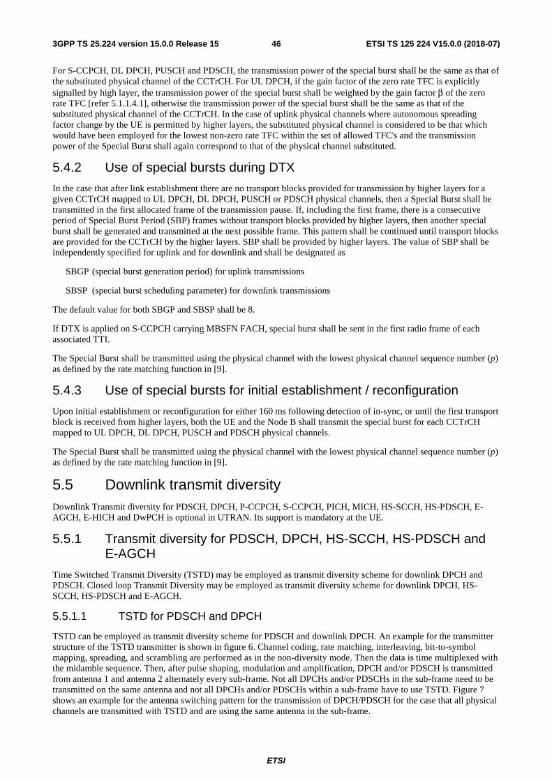
ETSI
ETSI TS 125 224 V15.0.0 (2018-07)463GPP TS 25.224 version 15.0.0 Release 15
For S-CCPCH, DL DPCH, PUSCH and PDSCH, the transmission power of the special burst shall be the same as that of the substituted physical channel of the CCTrCH. For UL DPCH, if the gain factor of the zero rate TFC is explicitly signalled by high layer, the transmission power of the special burst shall be weighted by the gain factor β of the zero rate TFC [refer 5.1.1.4.1], otherwise the transmission power of the special burst shall be the same as that of the substituted physical channel of the CCTrCH. In the case of uplink physical channels where autonomous spreading factor change by the UE is permitted by higher layers, the substituted physical channel is considered to be that which would have been employed for the lowest non-zero rate TFC within the set of allowed TFC's and the transmission power of the Special Burst shall again correspond to that of the physical channel substituted.
5.4.2 Use of special bursts during DTX
In the case that after link establishment there are no transport blocks provided for transmission by higher layers for a given CCTrCH mapped to UL DPCH, DL DPCH, PUSCH or PDSCH physical channels, then a Special Burst shall be transmitted in the first allocated frame of the transmission pause. If, including the first frame, there is a consecutive period of Special Burst Period (SBP) frames without transport blocks provided by higher layers, then another special burst shall be generated and transmitted at the next possible frame. This pattern shall be continued until transport blocks are provided for the CCTrCH by the higher layers. SBP shall be provided by higher layers. The value of SBP shall be independently specified for uplink and for downlink and shall be designated as
SBGP (special burst generation period) for uplink transmissions
SBSP (special burst scheduling parameter) for downlink transmissions
The default value for both SBGP and SBSP shall be 8.
If DTX is applied on S-CCPCH carrying MBSFN FACH, special burst shall be sent in the first radio frame of each associated TTI.
The Special Burst shall be transmitted using the physical channel with the lowest physical channel sequence number (p) as defined by the rate matching function in [9].
5.4.3 Use of special bursts for initial establishment / reconfiguration
Upon initial establishment or reconfiguration for either 160 ms following detection of in-sync, or until the first transport block is received from higher layers, both the UE and the Node B shall transmit the special burst for each CCTrCH mapped to UL DPCH, DL DPCH, PUSCH and PDSCH physical channels.
The Special Burst shall be transmitted using the physical channel with the lowest physical channel sequence number (p) as defined by the rate matching function in [9].
5.5 Downlink transmit diversity Downlink Transmit diversity for PDSCH, DPCH, P-CCPCH, S-CCPCH, PICH, MICH, HS-SCCH, HS-PDSCH, E-AGCH, E-HICH and DwPCH is optional in UTRAN. Its support is mandatory at the UE.
5.5.1 Transmit diversity for PDSCH, DPCH, HS-SCCH, HS-PDSCH and E-AGCH
Time Switched Transmit Diversity (TSTD) may be employed as transmit diversity scheme for downlink DPCH and PDSCH. Closed loop Transmit Diversity may be employed as transmit diversity scheme for downlink DPCH, HS-SCCH, HS-PDSCH and E-AGCH.
5.5.1.1 TSTD for PDSCH and DPCH
TSTD can be employed as transmit diversity scheme for PDSCH and downlink DPCH. An example for the transmitter structure of the TSTD transmitter is shown in figure 6. Channel coding, rate matching, interleaving, bit-to-symbol mapping, spreading, and scrambling are performed as in the non-diversity mode. Then the data is time multiplexed with the midamble sequence. Then, after pulse shaping, modulation and amplification, DPCH and/or PDSCH is transmitted from antenna 1 and antenna 2 alternately every sub-frame. Not all DPCHs and/or PDSCHs in the sub-frame need to be transmitted on the same antenna and not all DPCHs and/or PDSCHs within a sub-frame have to use TSTD. Figure 7 shows an example for the antenna switching pattern for the transmission of DPCH/PDSCH for the case that all physical channels are transmitted with TSTD and are using the same antenna in the sub-frame.
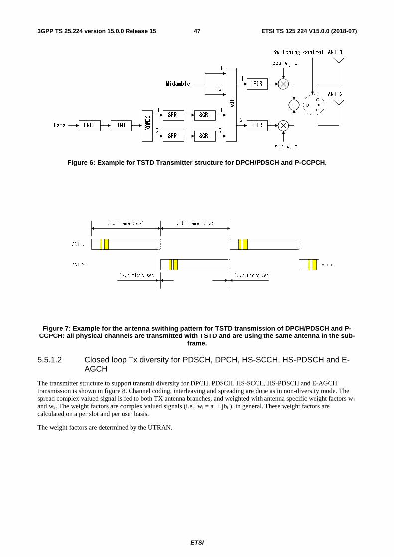
ETSI
ETSI TS 125 224 V15.0.0 (2018-07)473GPP TS 25.224 version 15.0.0 Release 15
Figure 6: Example for TSTD Transmitter structure for DPCH/PDSCH and P-CCPCH.
Figure 7: Example for the antenna swithing pattern for TSTD transmission of DPCH/PDSCH and P-
CCPCH: all physical channels are transmitted with TSTD and are using the same antenna in the sub-frame.
5.5.1.2 Closed loop Tx diversity for PDSCH, DPCH, HS-SCCH, HS-PDSCH and E-AGCH
The transmitter structure to support transmit diversity for DPCH, PDSCH, HS-SCCH, HS-PDSCH and E-AGCH transmission is shown in figure 8. Channel coding, interleaving and spreading are done as in non-diversity mode. The spread complex valued signal is fed to both TX antenna branches, and weighted with antenna specific weight factors w1 and w2. The weight factors are complex valued signals (i.e., wi = ai + jbi ), in general. These weight factors are calculated on a per slot and per user basis.
The weight factors are determined by the UTRAN.
I
QMidamble
INTENCData
DEMUX
I
QSPR SCR
SPR SCRI
Q
TDM
FIRI
cos wc t
FIRQ
-sin wc t
Switching control ANT 1
ANT 2
Sub-frame (5ms)Sub-frame (5ms)
ANT 1
ANT 2
12.5 micro sec 12.5 micro sec
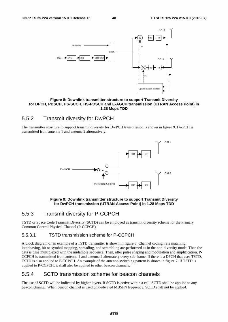
ETSI
ETSI TS 125 224 V15.0.0 (2018-07)483GPP TS 25.224 version 15.0.0 Release 15
Figure 8: Downlink transmitter structure to support Transmit Diversity for DPCH, PDSCH, HS-SCCH, HS-PDSCH and E-AGCH transmission (UTRAN Access Point) in
1.28 Mcps TDD
5.5.2 Transmit diversity for DwPCH
The transmitter structure to support transmit diversity for DwPCH transmission is shown in figure 9. DwPCH is transmitted from antenna 1 and antenna 2 alternatively.
Figure 9: Downlink transmitter structure to support Transmit Diversity for DwPCH transmission (UTRAN Access Point) in 1.28 Mcps TDD
5.5.3 Transmit diversity for P-CCPCH
TSTD or Space Code Transmit Diversity (SCTD) can be employed as transmit diversity scheme for the Primary Common Control Physical Channel (P-CCPCH)
5.5.3.1 TSTD transmission scheme for P-CCPCH
A block diagram of an example of a TSTD transmitter is shown in figure 6. Channel coding, rate matching, interleaving, bit-to-symbol mapping, spreading, and scrambling are performed as in the non-diversity mode. Then the data is time multiplexed with the midamble sequence. Then, after pulse shaping and modulation and amplification, P-CCPCH is transmitted from antenna 1 and antenna 2 alternately every sub-frame. If there is a DPCH that uses TSTD, TSTD is also applied to P-CCPCH. An example of the antenna-switching pattern is shown in figure 7. If TSTD is applied to P-CCPCH, it shall also be applied to other beacon channels.
5.5.4 SCTD transmission scheme for beacon channels
The use of SCTD will be indicated by higher layers. If SCTD is active within a cell, SCTD shall be applied to any beacon channel. When beacon channel is used on dedicated MBSFN frequency, SCTD shall not be applied.
MUX
INTENCData
Midamble w1
w2
FIR RF
FIR RF
Uplink channel estimate
ANT1
ANT2SPR+SCR
DwPCH
FIR RF
Ant 2
FIR RF
Ant 1
Switching Control
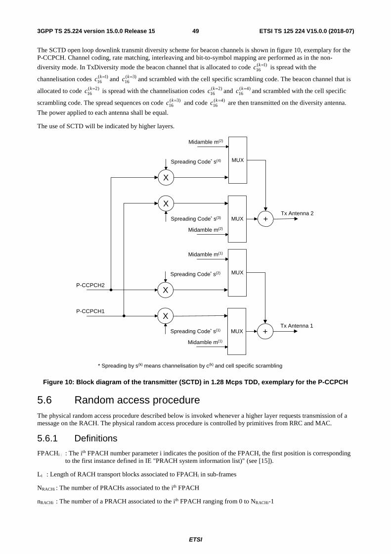
ETSI
ETSI TS 125 224 V15.0.0 (2018-07)493GPP TS 25.224 version 15.0.0 Release 15
The SCTD open loop downlink transmit diversity scheme for beacon channels is shown in figure 10, exemplary for the P-CCPCH. Channel coding, rate matching, interleaving and bit-to-symbol mapping are performed as in the non-
diversity mode. In TxDiversity mode the beacon channel that is allocated to code is spread with the
channelisation codes and and scrambled with the cell specific scrambling code. The beacon channel that is
allocated to code is spread with the channelisation codes and and scrambled with the cell specific
scrambling code. The spread sequences on code and code are then transmitted on the diversity antenna.
The power applied to each antenna shall be equal.
The use of SCTD will be indicated by higher layers.
Figure 10: Block diagram of the transmitter (SCTD) in 1.28 Mcps TDD, exemplary for the P-CCPCH
5.6 Random access procedure The physical random access procedure described below is invoked whenever a higher layer requests transmission of a message on the RACH. The physical random access procedure is controlled by primitives from RRC and MAC.
5.6.1 Definitions
FPACHi : : The ith FPACH number parameter i indicates the position of the FPACH, the first position is corresponding to the first instance defined in IE "PRACH system information list)" (see [15]).
Li : Length of RACH transport blocks associated to FPACHi in sub-frames
NRACHi : The number of PRACHs associated to the ith FPACH
nRACHi : The number of a PRACH associated to the ith FPACH ranging from 0 to NRACHi-1
)1(16
=kc)1(
16=kc )3(
16=kc
)2(16
=kc )2(16
=kc )4(16
=kc)3(
16=kc )4(
16=kc
* Spreading by s(k) means channelisation by c(k) and cell specific scrambling
MUX
X
X
+Midamble m(1)
Spreading Code* s(2)
Spreading Code* s(1)
P-CCPCH2
P-CCPCH1
Tx Antenna 1
MUX
Midamble m(1)
MUX
X
X
+Midamble m(2)
Spreading Code* s(4)
Spreading Code* s(3)Tx Antenna 2
MUX
Midamble m(2)
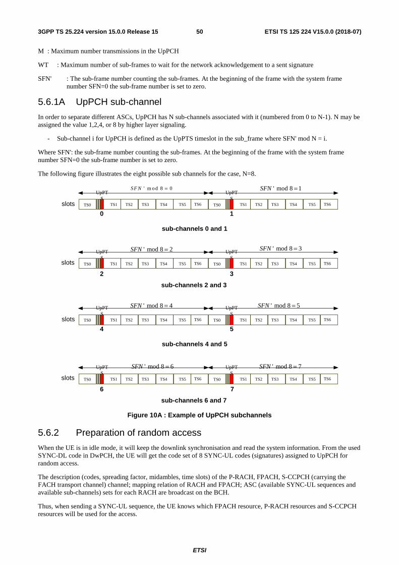
ETSI
ETSI TS 125 224 V15.0.0 (2018-07)503GPP TS 25.224 version 15.0.0 Release 15
M : Maximum number transmissions in the UpPCH
WT : Maximum number of sub-frames to wait for the network acknowledgement to a sent signature
SFN' : The sub-frame number counting the sub-frames. At the beginning of the frame with the system frame number SFN=0 the sub-frame number is set to zero.
5.6.1A UpPCH sub-channel
In order to separate different ASCs, UpPCH has N sub-channels associated with it (numbered from 0 to N-1). N may be assigned the value 1,2,4, or 8 by higher layer signaling.
- Sub-channel i for UpPCH is defined as the UpPTS timeslot in the sub_frame where SFN' mod N = i.
Where SFN': the sub-frame number counting the sub-frames. At the beginning of the frame with the system frame number SFN=0 the sub-frame number is set to zero.
The following figure illustrates the eight possible sub channels for the case, N=8.
slots
slots
sub-channels 0 and 1
0 1
32
sub-channels 2 and 3
UpPTS
TS0 TS1 TS2 TS3 TS4 TS5 TS6
UpPTS
TS0 TS1 TS2 TS3 TS4 TS5 TS6
UpPTS
TS0 TS1 TS2 TS3 TS4 TS5 TS6
UpPTS
TS0 TS1 TS2 TS3 TS4 TS5 TS6
slots
slots
sub-channels 4 and 5
4 5
76
sub-channels 6 and 7
UpPTS
TS0 TS1 TS2 TS3 TS4 TS5 TS6
UpPTS
TS0 TS1 TS2 TS3 TS4 TS5 TS6
UpPTS
TS0 TS1 TS2 TS3 TS4 TS5 TS6
UpPTS
TS0 TS1 TS2 TS3 TS4 TS5 TS6
' m od 8 0SF N = ' mod 8 1SFN =
' mod 8 2SFN =
' mod 8 4SFN =
' mod 8 3SFN =
' mod 8 5SFN =
' mod 8 6SFN = ' mod 8 7SFN =
Figure 10A : Example of UpPCH subchannels
5.6.2 Preparation of random access
When the UE is in idle mode, it will keep the downlink synchronisation and read the system information. From the used SYNC-DL code in DwPCH, the UE will get the code set of 8 SYNC-UL codes (signatures) assigned to UpPCH for random access.
The description (codes, spreading factor, midambles, time slots) of the P-RACH, FPACH, S-CCPCH (carrying the FACH transport channel) channel; mapping relation of RACH and FPACH; ASC (available SYNC-UL sequences and available sub-channels) sets for each RACH are broadcast on the BCH.
Thus, when sending a SYNC-UL sequence, the UE knows which FPACH resource, P-RACH resources and S-CCPCH resources will be used for the access.
ETSI
ETSI TS 125 224 V15.0.0 (2018-07)513GPP TS 25.224 version 15.0.0 Release 15
The physical random access procedure described in this sub-clause is initiated upon request from the MAC sub-layer (see [18] and [19]).
Before the physical random-access procedure can be initiated, Layer 1 shall receive the following information by a CPHY-TrCH-Config-REQ from the RRC layer:
- The uplink access position by higher layers.
- The association between which signatures and which FPACHs; which FPACHs and which PRACHs; including the parameter values for each listed physical channel.
- The length Li of a RACH message associated to FPACHi can be configured to be either 1 or 2 or 4 sub-frames corresponding to a length in time of either 5 ms or 10 ms or 20 ms.
NOTE 1: NRACHi PRACHs can be associated with to FPACHi. The maximum allowed
NRACHi is Li.
- The available UpPCH sub-channels for each Access Service Class (ASC);
- The set of Transport Format parameters for the PRACH message;
- The "M" maximum number transmissions in the UpPCH;
- The "WT" maximum number of sub-frames to wait for the network acknowledgement to a sent signature; (1..4) the maximum value supported by Layer 1 is 4 sub-frames.
- The initial signature power "Signature_Initial_Power";
- The power-ramping factor Power Ramp Step [Integer];
The above parameters may be updated from higher layers before each physical random access procedure is initiated.
At each initiation of the physical random access procedure, Layer 1 shall receive the following information from the higher layers (MAC):
- The Transport Format to be used for the specific PRACH message;
- The ASC for the specific Random Access procedure;
- The data to be transmitted (Transport Block Set).
- The type of random access
5.6.3 Random access procedure
The physical random-access procedure shall be performed as follows:
UE side:
1 Set the Signature Re-Transmission Counter to M.
2 Set the Signature transmission power to Signature_Initial_Power.
3 Based on the type of random access and the transport format indicated by MAC layer, an E-RUCCH or unique RACH used for the radio access is chosen, and then randomly select one UpPCH sub-channel and one signature respectively from the available ones for the given ASC. The random function shall be such that each of the allowed selections is chosen with equal probability.
4 Transmit the signature at UpPCH or other uplink access position indicated by higher layers using the selected UpPCH sub-channel at the signature transmission power. In the case that the Commanded Signature transmission Power exceeds the maximum allowed value, set the Signature transmission Power to the maximum allowed power.
5 After sending a signature, listen to the relevant FPACH for the next WT sub-frames to get the network acknowledgement. The UE will read the FPACHi associated to the transmitted UpPCH only in the sub-frames fulfilling the following relation:
ETSI
ETSI TS 125 224 V15.0.0 (2018-07)523GPP TS 25.224 version 15.0.0 Release 15
(SFN' mod Li)=nRACHi ; nRACHi=0,…, NRACHi-1, Here, FPACH to which UE should listen is decided according to the following formula:
FPACHi= N mod M,
Where, N denotes the signature number (0..7) and M denotes the maximum number of FPACHs that defined in the cell.
6 In case no valid answer is detected in the due time: Increase the Signature transmission power by ΔP0 = Power Ramp Step [dB], decrease the Signature Re-transmission counter by one and if it is still greater than 0, then repeat from step 3; else report a random access failure to the MAC sub-layer.
7 In case a valid answer is detected in the due time
a) set the timing and power level values according to the indication received by the network in the FPACHi
b) send at the sub-frame coming 2 sub-frames after the one carrying the signature acknowledgement, the RACH message on the relevant PRACH. In case Li is bigger than one and the sub-frame number of the acknowledgement is odd the UE will wait one more sub-frame. The relevant PRACH is the nRACHi
th PRACH associated to the FPACHi if the following equation ifs fulfilled:
(SFN' mod Li)=nRACHi ;
Here SFN' is the sub-frame number of the arrival of the acknowledgement.
Both on the UpPCH and on the PRACH, the transmit power level shall never exceed the indicated value signalled by the network.
Network side:
- The node B will transmit the FPACHi associated with the received UpPCH only in the sub-frames fulfilling the following relation:
(SFN' mod L)=nRACHi ; nRACHi=0,…, NRACHi-1,
Here, FPACH number i is selected according to the following formula based on acknowledged signature:
FPACHi= N mod M,
Where, N denotes the signature number (0..7) and M denotes the maximum number of FPACH that defined in the cell.
- The Node B will not acknowledge UpPCHs transmitted more than WT sub-frames ago
At the reception of a valid signature:
- Measure the timing deviation with respect to the reference time Tref of the received first path in time from the UpPCH and acknowledge the detected signature sending the FPACH burst on the relevant FPACH.
For examples on the random access procedure refer to Annex CB.
5.6.3.1 The use and generation of the information fields transmitted in the FPACH
The Fast Physical Access CHannel (FPACH) is used by the Node B to carry, in a single burst, the acknowledgement of a detected signature with timing and power level adjustment indication to a user equipment.
The length and coding of the information fields is explained in TS25.221 sub-clause 5A.3.3.1 .
5.6.3.1.1 Signature reference number
The Signature Reference Number field contains the number of the acknowledged signature. The user equipment shall use this information to verify whether it is the recipient of the FPACH message.
5.6.3.1.2 Relative sub-frame number
The Relative Sub-Frame Number field indicates the current sub-frame number with respect to the sub-frame at which the acknowledged signature has been detected.
ETSI
ETSI TS 125 224 V15.0.0 (2018-07)533GPP TS 25.224 version 15.0.0 Release 15
The user equipment shall use this information to verify whether it is the recipient of the FPACH message.
5.6.3.1.3 Received starting position of the UpPCH (UpPCHPOS)
The received starting position of the UpPCH (UpPCHPOS) field indirectly indicates to the user equipment the timing adjustment it has to implement for the following transmission to the network. The node B computes the proper value for this parameter according to the following rules: UpPCHPOS = UpPCHRxpath - UpPCHTS
where
UpPCHRxpath: time of the reception in the Node B of the SYNC-UL to be used in the uplink synchronization process
UpPCHTS: time instance 128 chips prior to the start of the UpPCH according to the Node B internal timing
This information shall be used by the UE to adjust its timing when accessing the network, as described in section [5.2 'Uplink Synchronisation'] .
5.6.3.1.4 Transmit power level command for the RACH message
This field indicates to the user equipment the power level to use for the RACH message transmission on the FPACH associated P-RACH.
The network may set this value based on the measured interference level (I) (in dBm) on the specific PRACH and on the desired signal to interference ratio (SIR) (in dB) on this channel as follows:
Transmit Power Level Command for the PRACH(PRXPRACH,des)
PRXPRACH,des is the desired receive power level on the PRACH.
The UE shall add to this value the estimated path-loss to compute the power level to transmit for the PRACH.
5.6.3A E-RUCCH procedure
Requests for the transmission of an E-RUCCH are controlled by higher layers [18].
The available eight SYNC_UL signatures on the primary carrier in a cell is devided into two subsets, one for the access of RACH information and the other for the access of E-RUCCH information. The available eight SYNC-UL signature on the secondary frequencies in cell are all for the access of E-RUCCH information.
When a Node B detects a SYNC_UL signature and acknowledges it on the related FPACH, it should do some recordings, including the FPACH channel number, the sub-frame on which the acknowledgement is sent and the SYNC_UL signature number. When a PRACH or E-RUCCH comes from a UE, the Node B should derive the related FPACH and the sub-frame on which the acknowledgement was sent for the UE and find the right record. The signature number in the record can help the Node B know the access type.
Random access procedure for enhanced uplink is basically same as random access procedure in subclause 5.6.3, only adding some new definitions.
LiE is the Length of E-RUCCH information transport blocks associated to FPACHi in sub-frames.
NRACHi is the number of PRACHs associated to the ith FPACH.
NE-RUCCHi is the number of E-RUCCHs associated to the ith FPACH and NE-RUCCHi equals to },min{ iERACHi LN .
When SF of PRACH code equals to 16, LiE will be 2, otherwise LiE will be 1。
When SF of PRACH code equals to 4, SF of E-RUCCH will be 8, otherwise E-RUCCHs has the same SF with PRACH.
When nE-RUCCHi equals to nRACHi, E-RUCCH will share the same code resource with PRACH. And when SF of PRACH code equals to 4, the code resource assigned to PRACH including two codes (code i and code i+1) of SF 8, E-RUCCH can use the ith code of SF 8.
If FPACHi sent an acknowledgement for E-RUCCH information, the sub-frames on which an acknowledgement is sent on FPACHi is fulfilling the following relation:
ETSI
ETSI TS 125 224 V15.0.0 (2018-07)543GPP TS 25.224 version 15.0.0 Release 15
(SFN' mod LiE)=nE-RUCCHi ; nE-RUCCHi=0,…, NE-RUCCHi-1,
Where, SFN' is the sub-frame number of the acknowledgement on FPACH
Accordingly, the code resource assigned to PRACH may be used by PRACH or E-RUCCH, we should make two prescript avoiding the collision between PRACH and E-RUCCH.
When Node B sent a FPACHi for nRACHiPRACH in sub frame K,Node B could not send a FPACHi for
RUCCHiEnRUCCHE−
− before sub frame K+Li;
When Node B sent a FPACHi for RUCCHiEnRUCCHE
−− in sub frame K,Node B could not send a FPACHi for
nRACHiPRACH before sub frame K+LiE。
The interval between the acknowledgement on FPACH and transmission of E-RUCCH is fixed for a UE. The UE will send at the sub-frame coming 2 sub-frames after the one carrying the signature acknowledgement. In case LiE is bigger than one and the sub-frame number of the acknowledgement is odd the UE will wait one more sub-frame.
The transmission power and the transmission timing are set according to subclause 5.1.1.7 and 5.2.7 respectively.
5.6.4 Random access collision
When a collision is very likely or in bad propagation environment, the Node B does not transmit the FPACH or cannot receive the SYNC-UL. In this case, the UE will not get any response from the Node B. Thus the UE will have to adjust its Tx time and Tx power level based on a new measurement and send a SYNC-UL again after a random delay.
Note that at each (re-)transmission, the SYNC-UL sequence and the UpPCH sub-channel will be randomly selected again by the UE.
Note: Due to the two-step approach a collision most likely happens on the UpPCH. The resources allocated to PRACH and E-RUCCH are virtually collision free. This two-step approach will guarantee that the RACH resources can be handled with conventional traffic on the same UL time slots.
5.7 Node B synchronisation procedure over the air An option exists to use the regular DwPCH transmissions to achieve and maintain Node B synchronisation [20]. This optional procedure is based on measurements of DwPCHs from neighbouring cells according to an RNC schedule. The timing offset measurements are reported back to the RNC for processing. The RNC generates cell timing updates that are transmitted to the Node Bs and cells for implementation (common with the 3.84 Mcps TDD option). Alternatively the RNC may indicate that the NodeB shall autonomously adjust the cell timings. Two distinct phases can be distinguished for Node B synchronisation over the air, with a potential additional sub-phase involving late entrant cells.
5.7.1 Initial synchronisation
Common with 3.84 Mcps TDD, see [4.9.2 Initial Synchronisation], however, the regular DwPCHs are used as cell sync bursts.
5.7.2 Steady-state phase
Common with 3.84 Mcps TDD, see [4.9.3 Steady-State Phase], however, the regular DwPCHs are used as cell sync bursts. If the NodeB adjusts the cell timings autonomously, it shall take into account the propagation delay, signaled by the RNC.
5.7.3 Late entrant cells
A procedure that may be used for introducing new cells into an already synchronised RNS involves the continuous measurement of the DwPCHs of the neighbouring cells by the late entrant cell. The RNC may use this information to adjust the late entrant cell sufficiently to allow the cell to enter steady state phase.
ETSI
ETSI TS 125 224 V15.0.0 (2018-07)553GPP TS 25.224 version 15.0.0 Release 15
5.8 Idle periods for IPDL location method
5.8.1 General
To support time difference measurements for location services, idle periods can be created in the downlink (hence the name IPDL) during which time transmission of the DwPCH from a Node B is temporarily ceased. During these idle periods the visibility of neighbour cells from the UE is improved.
The idle periods are arranged in a determined pattern according to higher layer parameters. An idle period has a duration of one DwPTS.
In general there are two modes for these idle periods:
- Continuous mode, and
- Burst mode
In continuous mode, the idle periods are active all the time. In burst mode the idle periods are arranged in bursts where each burst contains enough idle periods to allow a UE to make sufficient measurements for its location to be calculated. The bursts are separated by a period where no idle periods occur. The time difference measurements can be performed on any channel.
5.8.2 Parameters of IPDL
The following parameters are signalled to the UE via higher layers:
IP_Status: This is a logic value that indicates if the idle periods are arranged in continuous or burst mode.
IP_Spacing: The number of 10 ms radio frames between the start of a radio frame that contains an idle period and the next radio frame that contains the next idle period.
IP_Start: The number of the first frame with idle periods. In case of continuous mode IP_Start is the SFN of the first frame with idle periods and in case of burst mode IP_Start defines the number of frames after Burst_Start with the first frame with idle periods.
IP_Sub: Indicates whether the idle period is to occur in the odd, the even or both the odd and even 5 ms sub-frames of the 10 ms idle frame.
Additionally in the case of burst mode operation the following parameters are also communicated to the UE.
Burst_Start: Specifies the start of the first burst of idle periods. 256×Burst_Start is the SFN where the first burst of idle periods starts.
Burst_Length: The number of idle periods in a burst of idle periods.
Burst_Freq: Specifies the time between the start of a burst and the start of the next burst. 256×Burst_Freq is the number of radio frames between the start of a burst and the start of the next burst.
5.8.3 Calculation of idle period position
In burst mode, burst #0 starts in the radio frame with SFN = 256×Burst_Start. Burst #n starts in the radio frame with SFN = 256×Burst_Start + n×256×Burst_Freq ( n = 0,1,2, …). The sequence of bursts according to this formula continues up to and including the radio frame with SFN = 4095. At the start of the radio frame with SFN = 0, the burst sequence is terminated (no idle periods are generated) and at SFN = 256×Burst_Start the burst sequence is restarted with burst #0 followed by burst #1 etc., as described above.
Continuous mode is equivalent to burst mode, with only one burst spanning the whole SFN cycle of 4096 radio frames, this burst starts in the radio frame with SFN = 0. In case of continuous mode the parameter IP_Start defines the first frame with idle periods.
The DwPCH, that has to be idle, is defined by two values: IP_Frame(x) and IP_Sub. IP_Frame(x) defines the xth frame within a burst in which subframe with the number IP_Sub has to be switched off.
The actual frame with idle periods within a burst is calculated as follows:
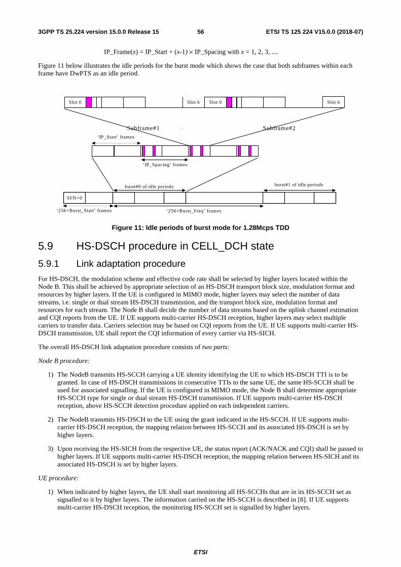
ETSI
ETSI TS 125 224 V15.0.0 (2018-07)563GPP TS 25.224 version 15.0.0 Release 15
IP_Frame(x) = IP_Start + (x-1) × IP_Spacing with x = 1, 2, 3, ....
Figure 11 below illustrates the idle periods for the burst mode which shows the case that both subframes within each frame have DwPTS as an idle period.
Subframe#1 Subframe#2
SFN=0
‘256×Burst_Start’ frames ‘256×Burst_Freq’ frames
burst#0 of idle periods
burst#1 of idle periods
‘IP_Spacing’ frames
‘IP_Start’ frames
Slot 0 Slot 6 Slot 0 Slot 6
Figure 11: Idle periods of burst mode for 1.28Mcps TDD
5.9 HS-DSCH procedure in CELL_DCH state
5.9.1 Link adaptation procedure
For HS-DSCH, the modulation scheme and effective code rate shall be selected by higher layers located within the Node B. This shall be achieved by appropriate selection of an HS-DSCH transport block size, modulation format and resources by higher layers. If the UE is configured in MIMO mode, higher layers may select the number of data streams, i.e. single or dual stream HS-DSCH transmission, and the transport block size, modulation format and resources for each stream. The Node B shall decide the number of data streams based on the uplink channel estimation and CQI reports from the UE. If UE supports multi-carrier HS-DSCH reception, higher layers may select multiple carriers to transfer data. Carriers selection may be based on CQI reports from the UE. If UE supports multi-carrier HS-DSCH transmission, UE shall report the CQI information of every carrier via HS-SICH.
The overall HS-DSCH link adaptation procedure consists of two parts:
Node B procedure:
1) The NodeB transmits HS-SCCH carrying a UE identity identifying the UE to which HS-DSCH TTI is to be granted. In case of HS-DSCH transmissions in consecutive TTIs to the same UE, the same HS-SCCH shall be used for associated signalling. If the UE is configured in MIMO mode, the Node B shall determine appropriate HS-SCCH type for single or dual stream HS-DSCH transmission. If UE supports multi-carrier HS-DSCH reception, above HS-SCCH detection procedure applied on each independent carriers.
2) The NodeB transmits HS-DSCH to the UE using the grant indicated in the HS-SCCH. If UE supports multi-carrier HS-DSCH reception, the mapping relation between HS-SCCH and its associated HS-DSCH is set by higher layers.
3) Upon receiving the HS-SICH from the respective UE, the status report (ACK/NACK and CQI) shall be passed to higher layers. If UE supports multi-carrier HS-DSCH reception, the mapping relation between HS-SICH and its associated HS-DSCH is set by higher layers.
UE procedure:
1) When indicated by higher layers, the UE shall start monitoring all HS-SCCHs that are in its HS-SCCH set as signalled to it by higher layers. The information carried on the HS-SCCH is described in [8]. If UE supports multi-carrier HS-DSCH reception, the monitoring HS-SCCH set is signalled by higher layers.
ETSI
ETSI TS 125 224 V15.0.0 (2018-07)573GPP TS 25.224 version 15.0.0 Release 15
2) In the case that a HS-SCCH is identified to be correct by its CRC, the UE shall read the HS-PDSCHs indicated by the HS-SCCH. If the UE is configured in MIMO mode, UE may acquire HS-PDSCH resource allocation information of each stream according to the associated HS-SCCH. If UE supports multi-carrier HS-DSCH reception, UE may acquire HS-PDSCH resource allocation information of each carrier according to the associated HS-SCCHs, the mapping relation between every HS-SCCH and its associated HS-PDSCH is signalled by higher layers. In the case that a HS-SCCH is identified to be incorrect, the UE shall discard the data on the HS-SCCH and return to monitoring.
3) After reading the HS-PDSCHs, the UE shall generate an ACK/NACK message and transmit this to the NodeB in the associated HS-SICH, along with the most recently derived CQI. If the UE is configured in MIMO mode, the CQI and ACK/NACK of each stream are transferred via the associated HS-SICH. If UE supports multi-carrier HS-DSCH reception, the CQI and ACK/NACK of every carrier are transferred via individual HS-SICH.
The mapping of HS-PDSCH channelisation code set and timeslot information carried by the HS-SCCH for a given HS-DSCH TTI is described in [9].
For a given allocation of HS-PDSCH resources to a UE for a specific HS-DSCH TTI, the following shall apply:
- If timeslot information on HS-SCCH indicates two or more timeslots, none of these timeslots shall comprise a beacon channel.
- If timeslot information on HS-SCCH indicates a single timeslot and this timeslot comprises a beacon channel then:
- The Node-B shall not indicate SF=1 for any HS-PDSCH resource.
- The set of HS-PDSCH resources allocated by the Node-B to a UE shall exclusively comprise either beacon function or non-beacon function physical channels. The Node B shall therefore not allocate both beacon function and non-beacon function physical channels within the beacon timeslot to the UE. If the HS-DSCH for a specific HS-DSCH TTI is mapped to the beacon channel, this shall be signalled using kstart = 1 and kstop = 1. For a definition of the first and last allocated channelisation code indices kstart and kstop on HS-SCCH refer to [9].
- When SCTD antenna diversity is applied to the beacon channel, then the presence of channelisation code )1(
16C within the channelisation code set information on HS-SCCH shall implicitly indicate the presence of
channelisation code )2(16C .
5.9.2 HS-DSCH channel quality indication procedure
For the HS-SICH associated to the HS-SCCH command for allocation or release of the semi-persistent HS-PDSCH resources and HS-SCCH command for activation or deactivation of DRX and the HS-SICH associated to HS-SCCH type1 or HS-SCCH type 4 or HS-SCCH type 8 with transport block size information set to all zeros, UE shall feedback ACK and CQI on HS-SICH with RTBS equals to zero.
The channel quality indicator (CQI) provides the Node B with an estimate of the code rate that would have maximized the single-transmission throughput of the previous HS-DSCH transmission if decoded in isolation. The CQI report requires to be referenced to a given set of HS-PDSCH resources by the Node B, but note that the UE is not restricted to making measurements only on these reference resources when deriving a given CQI. The reference resources for a CQI report shall be a set of HS-PDSCH resources that were received by the UE in a single TTI, and contain a complete transport block. These resources will be known to the Node B from the relative timings of the HS-SICH carrying the CQI and previous HS-DSCH transmissions to the UE.
The CQI consists of two fields; a Recommended Transport Block Size (RTBS) and a Recommended Modulation Format (RMF). The UE shall use the same mapping table for these fields as is being used for the time slot information and modulation scheme information fields respectively of the HS-SCCH [18]. If the UE is configured in MIMO mode, the HS-SICH shall consists of the CQI reports of each stream, i.e. the RTBS and RMF of each stream.
The reporting procedure is as follows:
1. The UE receives a message on an HS-SCCH telling it which resources have been allocated to it for the next associated HS-DSCH transmission.
ETSI
ETSI TS 125 224 V15.0.0 (2018-07)583GPP TS 25.224 version 15.0.0 Release 15
2. The UE reads the associated HS-DSCH transmission, and makes the necessary measurements to derive a CQI that it estimates would have given it the highest single-transmission throughput for the allocated resources whilst achieving a BLER of no more than 10 %. If the UE is configured in MIMO mode, the CQI would have given the highest single-transmission throughput for each stream respectively in the allocated resources whilst achieving BLER of each stream of no more than 10%.
BLER, in this context, is defined as the probability that a transport block transmitted using the RTBS and RMF is received in error if decoded in isolation. For the purposes of this calculation, it shall be assumed that the transport block that would be transmitted with these parameters would use redundancy version parameters s = 1 and r = 0. Note that, by this definition, a UE shall never report a CQI that corresponds to a code rate greater than unity.
Using this definition of BLER, single-transmission throughput shall be defined as follows :
single-transmission throughput = (1 – BLER) × RTBS
If the UE is configured in MIMO mode, the single-transmission throughput shall be defined as the sum of each stream throughput.
3. The CQI report derived from a given HS-DSCH transmission shall be reported to the Node B in the next HS-SICH available to the UE following that HS-DSCH transmission, unless that HS-SICH immediately follows the last allocated HS-DSCH timeslot, in which case the subsequent available HS-SICH shall be used by the UE. This HS-SICH may not necessarily be the same HS-SICH that carries the ACK/NACK information for that HS-DSCH transmission. The UE shall always transmit the most recently derived CQI in any given HS-SICH, which may mean that some CQI reports are discarded without being transmitted to the Node B.
5.9.3 HS-SCCH monitoring procedure
If HS_SCCH_DRX_Active is FALSE, UE shall monitor a set of HS-SCCHs as follows.
For 1.28Mcps TDD, in a multi-frequency HS-DSCH cell, a UE divides its HS-SCCH set into one or more HS-SCCH subsets; in each HS-SCCH subset all HS-SCCHs are associated with the same frequency's HS-PDSCH. When indicated by higher layers, the UE shall start monitoring all HS-SCCHs in all HS-SCCH subsets to acquire the configuration information of HS-PDSCHs. In the case that one HS-SCCH is detected carrying its UE identity, the UE shall skip monitoring the remaining HS-SCCHs in this HS-SCCH subset, and restrict its monitoring only to previously detected HS-SCCH in the following TTIs. The UE shall set all HS-SCCHs carrying its UE identity in all HS-SCCH subsets into an active set, and set all HS-SCCH subsets in which no HS-SCCH carries its UE identity into a remaining set.
In the case that the multi-carrier number (as described in [15]) is not configured by high layers, a UE shall always monitor all HS-SCCH subsets. Otherwise, the UE may skip monitoring remaining HS-SCCH subsets when the number of HS-SCCHs carrying its UE identity, i.e. the number of HS-SCCHs in the active set, is equal to the configured value.
During the following TTIs, the UE shall update and maintain the active set and the remaining set. If one or more HS-SCCHs in the active set do not carry its UE identity, the UE shall remove them from the active set and set their corresponding HS-SCCH subsets into remaining set. Meanwhile, if one or more HS-SCCHs in remaining sets are detected carrying its UE identity, the UE shall set these founded HS-SCCHs into the active set and remove their corresponding HS-SCCH subsets from the remaining set.
If HS_SCCH_DRX_Active is TRUE, UE shall monitor a set of HS-SCCHs in the subframes according to rules defined in the subclause 5.13.
5.9A HS-DSCH procedure in CELL_FACH state
5.9A.1 Link adaptation procedure
In HS-DSCH reception in CELL_FACH state, the measurement result on RACH can be used for initial link adaptation. Only when UE is allocated a dedicated UE identity, the ACK/NACK feedback is provided and a measurement report is associated with each HS-DSCH link adaptation procedure. When downlink transmission is recommenced following a transmission pause, Node B shall order UE to perform the uplink synchronization procedure cf [subclause 5.3.3.2 Establishment of uplink synchronization] in case it detects the UE is out of synchronization. If Node B receives E-RUCCH from the UE, the Node B can then resume the HS-DSCH transmission for the UE, and the link adaptation procedure is the same as that in CELL_DCH state, cf.5.9.1.
ETSI
ETSI TS 125 224 V15.0.0 (2018-07)593GPP TS 25.224 version 15.0.0 Release 15
The Node B shall always use HS-SCCH type 1 for BCCH transmission. For the UEs in CELL-FACH state which are configured in MU-MIMO mode, the UE shall detect the HS-SCCH type of the HS-SCCHs carry consistent control information via UE ID, i.e., the HS-SCCH shall be HS-SCCH type 1 if the UE ID is BCCH specific H-RNTI while the HS-SCCH shall be HS-SCCH type 4 if the UE ID is its dedicated H-RNTI.
5.9A.2 HS-DSCH channel quality indication procedure
If the UE is configured without dedicated UE identity, the UE shall not transmit an HS-SICH. If the UE is configured with a dedicated UE identity, but the HS-SCCH is an uplink synchronization establishment order, then its associated HS-SICH shall not be transmitted. Otherwise, the channel quality indication shall be transmitted on HS-SICH, and the HS-DSCH channel quality indication procedure is the same as that in CELL_DCH state of 1.28Mcps TDD, cf. 5.9.2.
5.9A.3 HS-SCCH monitoring procedure
When HS_DSCH_DRX_CELL_FACH_STATUS is FALSE (as described in [15]), UE shall monitor HS-SCCHs continuously as in CELL_DCH state cf. 5.9.3.
When HS_DSCH_DRX_CELL_FACH_STATUS is TRUE (as described in [15]), UE shall monitor HS-SCCHs according to the following rules:
- Once the UE receives HS-SCCH carrying its dedicated identity and feeds back on HS-SICH, the UE shall monitor HS-SCCHs continuously for a period of inactivity time (T321) configured by higher layer.
- Once the UE receives HS-SCCH order carrying synchronization establishment command and accomplishes the uplink synchronization establishment, the UE shall monitor HS-SCCHs continuously for a period of inactivity time (T321) configured by higher layer.
- Whenever the UE monitors E-AGCH continuously as described in 5.11.3A, the UE shall always monitor HS-SCCHs.
- The UE shall monitor HS-SCCHs for the RX burst length of the DRX Cycle and may choose not to monitor HS-SCCHs for the rest of the time of the DRX Cycle (as described in [15]).
5.9B HS-DSCH procedure in CELL_PCH or URA_PCH state
5.9B.1 Link adaptation procedure
In HS-DSCH reception in CELL_PCH and URA_PCH state, after receiving a paging indication on PICH for its specific PI, the UE with a stored dedicated UE identity shall start monitoring HS-SCCH while the UE without a dedicated UE identity shall start monitoring the HS-PDSCH(s). The HS-PDSCH physical resource and associated signalling are broadcasted in the system information.
In a multi-frequency cell, HS-DSCH reception in CELL_PCH and URA_PCH is only on primary frequency.
Node B procedure:
The timing relation of the PICH frame to the associated HS-SCCH subframe or the HS-DSCH is described in 7.2.7.3 and 7.2.7.4 of [8].
If the UE is configured with a dedicated UE identity, the Node B shall use the following procedures:
- The Node B shall transmit the HS-SCCH order associated with the PICH frame using the dedicated UE identity.
- If the Node B has received E-RUCCH, the Node B considers that the UE has transitted to CELL_FACH state.
If the UE is configured without dedicated UE identity, the Node B shall use the following procedures:
- The Node B shall not transmit an HS-SCCH.
- The Node B shall transmit an HS-DSCH transport block in the HS-DSCH subframe with parameters configured by RRC layer.
- The Node B shall retransmit the HS-DSCH transport block (2*m-1) times in the next contiguous subframes without transmitting HS-SCCH.
ETSI
ETSI TS 125 224 V15.0.0 (2018-07)603GPP TS 25.224 version 15.0.0 Release 15
- The Node B shall use QPSK modulation for each transmission of HS-PDSCH.
- For the first transmission and retransmission, the redundancy and constellation version of the HS-DSCH transport block are 0, 3, 4, 7, 0, 3…
UE procedure:
If the UE has detected a paging indication intended for this UE, the UE shall perform the following actions:
If the UE is configured with a dedicated UE identity, UE shall receive the corresponding HS-SCCH subframes:
- if the UE detects that one of the monitored HS-SCCHs in a set of associated HS-SCCH subframes carries consistent control information (HS-SCCH order) intended for this UE, the UE shall initiate the uplink synchronization procedure on primary frequency and transit to CELL_FACH state.
- if the UE detects that one of the monitored HS-SCCHs in a set of associated HS-SCCH subframes carries consistent control information (HS-SCCH type 1 carrying BCCH specific H-RNTI), the UE shall receive the corresponding HS-DSCH based on the association and timing between HS-SCCH and HS-DSCH.
- if the UE does not detect any HS-SCCH carries consistent control information intended for this UE in the M subframes, the UE shall resume the DRX operation.
If the UE is configured without dedicated UE identity and there is no legacy PCH channel, UE shall receive the corresponding HS-DSCH TTIs and:
- consider that paging message is retransmitted in 2*m subframes, the parameter m is the number of frame that a paging sub-channel occupies.
- combine retransmissions to the same HARQ buffer.
- pass the data to higher layers if the CRC is correct after decoding the data.
- resume the DRX operation if the CRC fails after receiving 2*m subframes.
5.9B.2 HS-DSCH channel quality indication procedure
The UE in CELL_PCH or URA_PCH state does not report CQI via HS-SICH.
5.9B.3 HS-SCCH monitoring procedure
The UE with a stored dedicated UE identity shall monitor HS-SCCH in M sub-frames after receiving its specific paging indication on PICH (as described in [8]).
The UE without a dedicated UE identity shall not monitor any HS-SCCH.
5.10 Macro-diversity procedure The macro-diversity procedure is the same as that of 3.84 Mcps TDD, cf. 4.12 Macro-diversity procedure.
5.11 E-DCH Procedure
5.11.1 ACK/NACK detection
The physical layer in the UE shall detect ACK or NACK contained within the E-HICH. Which E-HICH is associated with the corresponding E-DCH transmission is defined in [8].
5.11.2 Serving and neighbour cell pathloss metric derivation
The UE shall be capable of measuring the P-CCPCH RSCP of the serving cell and of intra-frequency and inter-frequency neighbour cells in accordance with [11]. The P-CCPCH transmit power (Pref) of the serving cell and of each neighbour cell (with a primary or a secondary frequency being the same as UE's current working frequency) in the monitored neighbour cell list shall be signalled by higher layers to the UE in order that the UE may estimate the mean pathloss to the serving cell (Lserv) and to each of the N neighbour cells in the monitored neighbour cell list (L1, L2, … LN). The pathloss used in the following formulas is a linear value, but not a logarithmic (dB) value.
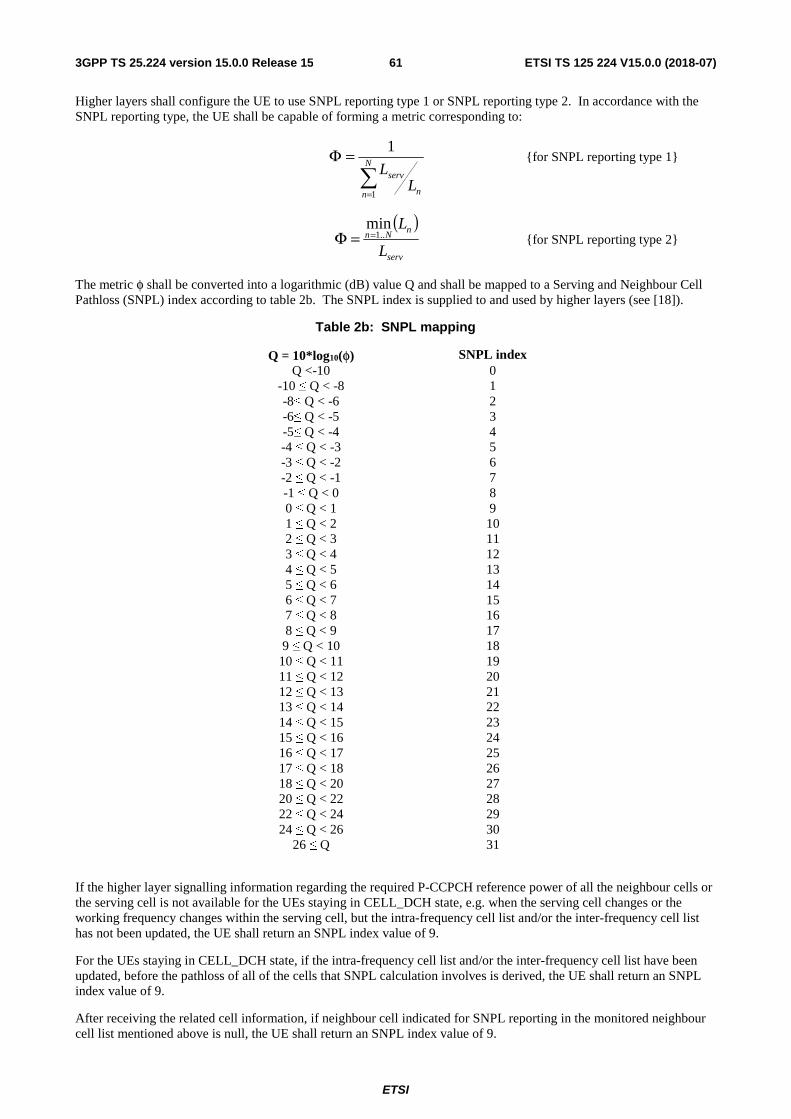
ETSI
ETSI TS 125 224 V15.0.0 (2018-07)613GPP TS 25.224 version 15.0.0 Release 15
Higher layers shall configure the UE to use SNPL reporting type 1 or SNPL reporting type 2. In accordance with the SNPL reporting type, the UE shall be capable of forming a metric corresponding to:
=
=Φ N
n n
servL
L
1
1 {for SNPL reporting type 1}
( )
serv
nNn
L
L..1
min==Φ {for SNPL reporting type 2}
The metric φ shall be converted into a logarithmic (dB) value Q and shall be mapped to a Serving and Neighbour Cell Pathloss (SNPL) index according to table 2b. The SNPL index is supplied to and used by higher layers (see [18]).
Table 2b: SNPL mapping
Q = 10*log10(φ) SNPL index Q <-10 0
-10 ≤ Q < -8 1 -8≤ Q < -6 2 -6≤ Q < -5 3 -5≤ Q < -4 4 -4 ≤ Q < -3 5 -3 ≤ Q < -2 6 -2 ≤ Q < -1 7 -1 ≤ Q < 0 8 0 ≤ Q < 1 9 1 ≤ Q < 2 10 2 ≤ Q < 3 11 3 ≤ Q < 4 12 4 ≤ Q < 5 13 5 ≤ Q < 6 14 6 ≤ Q < 7 15 7 ≤ Q < 8 16 8 ≤ Q < 9 17 9 ≤ Q < 10 18
10 ≤ Q < 11 19 11 ≤ Q < 12 20 12 ≤ Q < 13 21 13 ≤ Q < 14 22 14 ≤ Q < 15 23 15 ≤ Q < 16 24 16 ≤ Q < 17 25 17 ≤ Q < 18 26 18 ≤ Q < 20 27 20 ≤ Q < 22 28 22 ≤ Q < 24 29 24 ≤ Q < 26 30
26 ≤ Q 31
If the higher layer signalling information regarding the required P-CCPCH reference power of all the neighbour cells or the serving cell is not available for the UEs staying in CELL_DCH state, e.g. when the serving cell changes or the working frequency changes within the serving cell, but the intra-frequency cell list and/or the inter-frequency cell list has not been updated, the UE shall return an SNPL index value of 9.
For the UEs staying in CELL_DCH state, if the intra-frequency cell list and/or the inter-frequency cell list have been updated, before the pathloss of all of the cells that SNPL calculation involves is derived, the UE shall return an SNPL index value of 9.
After receiving the related cell information, if neighbour cell indicated for SNPL reporting in the monitored neighbour cell list mentioned above is null, the UE shall return an SNPL index value of 9.
ETSI
ETSI TS 125 224 V15.0.0 (2018-07)623GPP TS 25.224 version 15.0.0 Release 15
For the UE configured with multi-carrier E-DCH transmission, all the uplink E-DCH carriers of the UE can be divided into one or more carrier group(s). The neighbour cells which are used for SNPL calculation for each carrier in one carrier group are the same. For physical layer of UE, the carrier group information shall be indicated by higher layer to make it know that which uplink E-DCH carriers are in the same carrier group. For each carrier group, the SNPL is calculated in reference to one carrier of the carrier group and is shared by all the carriers which are in the same carrier group. Higher layers shall configure the UE to use SNPL reporting type 1 or SNPL reporting type 2 for all carrier groups. In accordance with the SNPL reporting type, the UE shall be capable of selecting the corresponding formula from the above two formulas to calculate the SNPL for one carrier group, where Lserv is the mean pathloss to the serving cell (Lserv) and Ln is the mean pathloss to the n-th cell of the N neighbour cells (with a primary or a secondary frequency being the same as one of the frequencies in the current carrier group) in the monitored neighbour cell list.
For multi-carrier E-DCH transmission, the UE shall return an SNPL index value of 9 for one carrier when the UE is under the same scenoarios as listed above for UE's returning an SNPL index value of 9.
5.11.3 E-AGCH monitoring in CELL_DCH state
If E-AGCH DRX information is not configured by higher layers,
if the UE has semi-persistent E-PUCH resources, the UE shall keep monitoring a set of E-AGCHs continuously;
otherwise, when the latest scheduling information UE sent indicates the TEBS equals zero and the UE has received the corresponding ACK on E-HICH, after continuing monitoring E-AGCH for a period of time configured by higher layers, the UE may stop monitoring E-AGCH if the UE has no E-DCH data (including retransmission data) to transmit. When the TEBS becomes larger than zero, the UE shall start monitoring E-AGCH after sending scheduling information indicating that the TEBS is larger than zero.
If the E-AGCH DRX information is configured by higher layers, the UE shall monitor E-AGCHs according to rules defined in the subclause 5.13.
5.11.3A E-AGCH monitoring in CELL_FACH state
For the UE with a stored dedicated UE identity in CELL_FACH state, when the latest scheduling information UE sent indicates the TEBS equals zero and the UE has received the corresponding ACK on E-HICH, after continuing monitoring E-AGCH for a period of time (T321) configured by higher layers (as described in [15]), UE may stop monitoring E-AGCH if the UE has no E-DCH data (including retransmission data) to transmit. The TEBS is described in [18].
If the TEBS becomes larger than zero, UE shall start monitoring E-AGCH after sending scheduling information indicating that the TEBS is larger than zero.
For the UE without a dedicated UE identity in CELL_FACH state or in IDLE mode, UE shall stop monitoring E-AGCH outside the common E-RNTI Scheduling Window (as described in [18]).
5.12 MIMO operation of HS-DSCH
5.12.1 General procedure
This section applies only when a UE is configured in MIMO mode.
The general transmitter structure to support MIMO operation of HS-PDSCH transmission is shown in figure 11A. Channel coding, interleaving and spreading are done the same as in non-MIMO mode. The Node B scheduler can decide to transmit one or two transport blocks to a UE in one TTI. The spread complex valued signals are fed to both TX antenna branches, and weighted with precoding weights.
If the UTRAN schedules a single transport block to a UE in one TTI, it uses EBB (Eigenvector Based Beam-forming) or antenna selection for transmission of that transport block on the HS-PDSCH sub-frame. If the UTRAN schedules two transport blocks to a UE in one TTI, it uses two orthogonal precoding vectors to transmit the two transport blocks. The precoding vectors are generated by SVD (Singular Value Decomposition) of the channel matrix or grouped beam-forming to form the two beams. The PARC with two transmit antennas can be viewed as a special case, where the stream per antenna is transmitted independently.
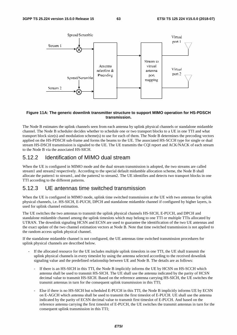
ETSI
ETSI TS 125 224 V15.0.0 (2018-07)633GPP TS 25.224 version 15.0.0 Release 15
⊗
⊗
Figure 11A: The generic downlink transmitter structure to support MIMO operation for HS-PDSCH transmission.
The Node B estimates the uplink channels seen from each antenna by uplink physical channels or standalone midamble channel. The Node B scheduler decides whether to schedule one or two transport blocks to a UE in one TTI and what transport block size(s) and modulation scheme(s) to use for each of them. The Node B determines the precoding vectors applied on the HS-PDSCH sub-frame and forms the beams to the UE. The associated HS-SCCH type for single or dual stream HS-DSCH transmission is signaled to the UE. The UE transmits the CQI report and ACK/NACK of each stream to the Node B via the associated HS-SICH.
5.12.2 Identification of MIMO dual stream
When the UE is configured in MIMO mode and the dual stream transmission is adopted, the two streams are called stream1 and stream2 respectively. According to the special default midamble allocation scheme, the Node B shall allocate the pattern1 to stream1, and the pattern2 to stream2. The UE identifies and detects two transport blocks in one TTI according to the different patterns.
5.12.3 UE antennas time switched transmission
When the UE is configured in MIMO mode, uplink time switched transmission at the UE with two antennas for uplink physical channels, i.e. HS-SICH, E-PUCH, DPCH and standalone midamble channel if configured by higher layers, is used for uplink channel estimation.
The UE switches the two antennas to transmit the uplink physical channels HS-SICH, E-PUCH, and DPCH and standalone midamble channel among the uplink timeslots which may belong to one TTI or multiple TTIs allocated by UTRAN. The downlink signaling HCSN and ECSN are used to guarantee the identification of the two UE antennas and the exact update of the two channel estimation vectors at Node B. Note that time switched transmission is not applied to the random access uplink physical channel.
If the standalone midamble channel is not configured, the UE antennas time switched transmission procedures for uplink physical channels are described below.
- If the allocated resource for the UE includes multiple uplink timeslots in one TTI, the UE shall transmit the uplink physical channels in every timeslot by using the antenna selected according to the received downlink signaling value and the predefined relationship between UE and Node B. The details are as follows:
- If there is an HS-SICH in this TTI, the Node B implicitly informs the UE by HCSN on HS-SCCH which antenna shall be used to transmit HS-SICH. The UE shall use the antenna indicated by the parity of HCSN decimal value to transmit HS-SICH. Based on the reference antenna carrying HS-SICH, the UE switches the transmit antennas in turn for the consequent uplink transmission in this TTI;
- Else if there is no HS-SICH but scheduled E-PUCH in this TTI, the Node B implicitly informs UE by ECSN on E-AGCH which antenna shall be used to transmit the first timeslot of E-PUCH. UE shall use the antenna indicated by the parity of ECSN decimal value to transmit first timeslot of E-PUCH. And based on the reference antenna carrying the first timeslot of E-PUCH, the UE switches the transmit antennas in turn for the consequent uplink transmission in this TTI;
ETSI
ETSI TS 125 224 V15.0.0 (2018-07)643GPP TS 25.224 version 15.0.0 Release 15
- Else, the UE shall take the antenna used to transmit the uplink channel in the first timeslot of this TTI as reference and switch the transmit antennas in turn in the consequent uplink timeslots in this TTI. The reference antenna is the other antenna different from the one used last time for this transmission type which may be non-scheduled transmission, semi-persistent transmission and RDI E-PUCH transmission.
- Else, the allocated resource for the UE just include one uplink timeslot in one TTI, the UE shall select the antenna according to the different uplink channel.
- If there is an HS-SICH in this uplink timeslot, the UE shall select the antenna indicated by the parity of HCSN decimal value on the associated HS-SCCH;
- Else if there is no HS-SICH but scheduled E-PUCH in this uplink timeslot, the UE shall select the antenna indicated by the parity of ECSN decimal value on E-AGCH;
- Else, the UE shall select the other antenna different from the one used last time for this transmission type which may be non-scheduled transmission, semi-persistent transmission and RDI E-PUCH transmission.
If the standalone midamble channel is configured, the UE antennas time switched transmission procedures for uplink physical channels are described below.
If the UE needs to transmit an HS-SICH, the UE shall use a different antenna from the one used for HS-SICH to transmit the associated standalone midamble channel in the other uplink timeslot of the same subframe configured by higher layers.
If there is other uplink physical channel(s) besides HS-SICH in subframe for the UE to transmit, the standalone midamble channel shall be omitted.
5.12A MU-MIMO operation of HS-DSCH and E-DCH If the UE is configured in MU-MIMO mode, the Node B should estimates the uplink channels seen from each antenna by uplink physical channels or standalone midamble channel. The Node B scheduler decides whether to schedule multiple UE using the same physical resource in one TTI according to uplink channel estimation.
For the MU-MIMO operation of HS-DSCH, the special default midamble pattern is signaled on HS-SCCH to inform the UE which special default midamble pattern is used. The UE transmits the CQI report and ACK/NACK to the Node B via the associated HS-SICH.
For the MU-MIMO operation of E-DCH, the special default midamble pattern is signaled on E-AGCH to inform the UE which special midamble pattern is used. The Node B transmits ACK/NACK to the each user via the associated E-HICH signature sequence.
5.13 Control channel discontinuous reception procedures If the higher layers set CONTROL_CHANNEL_DRX_STATUS to TRUE (as described in [15]) and Enabling_Delay is configured to be finite value, after Enabling_Delay radio frames have passed, UE_ DRX_Enabled is TRUE. Or if the higher layers set CONTROL_CHANNEL_DRX_STATUS to TRUE and Enabling_Delay is configured to be infinity, after the UE has received DRX activation order via HS-SCCH order, UE_DRX_Enabled is TRUE. Otherwise UE_ DRX_Enabled is FALSE.
Whether discontinuous downlink HS-SCCH reception operation or discontinuous downlink E-AGCH reception operation is applied is determined by the setting of HS_SCCH_DRX_Active and E_AGCH_DRX_Active as follows:
HS_SCCH_DRX_Active shall be set to TRUE while UE_ DRX_Enabled is TRUE and discontinuous downlink HS-SCCH reception is activated. Otherwise, HS-SCCH _DRX_Active shall be set to FALSE.
Discontinuous downlink HS-SCCH reception shall be activated at the time when UE_ DRX_Enabled is set to TRUE, and may be further deactivated or activated by layer 1 HS-SCCH orders (see section 5.13.2).
E_AGCH_DRX_Active shall be set to TRUE while UE_DRX_Enabled is TRUE, E-AGCH DRX information is configured and discontinuous downlink E-AGCH reception is activated. Otherwise, E_AGCH_DRX_Active shall be set to FALSE.
Discontinuous downlink E-AGCH reception shall be activated at the time when UE_ DRX_Enabled is set to TRUE and E-AGCH DRX information is configured and may be further deactivated or activated by layer 1 HS-SCCH orders.
ETSI
ETSI TS 125 224 V15.0.0 (2018-07)653GPP TS 25.224 version 15.0.0 Release 15
The higher layers define the discontinuous reception procedures using the following parameters (defined in [15]):
HS_SCCH_DRX Offset: HS-SCCH reception pattern offset in subframes.
E_AGCH_DRX Offset: E-AGCH reception pattern offset in subframes.
Enabling_Delay: ensures that the HS-SCCHs and E-AGCHs are received continuously for Enabling_Delay radio frames after CONTROL_CHANNEL_DRX_STATUS is set to TRUE.
HS_SCCH_DRX cycle: HS-SCCH reception pattern length in subframes.
E_AGCH_DRX cycle: E-AGCH reception pattern length in subframes.
Inactivity_Threshold_for_HS_SCCH_DRX_cycle: For single carrier HS-DSCH reception, when HS_SCCH _DRX_Active is TRUE, this timer shall be started or restarted in the same subframe as the HS-SICH corresponding to an HS-PDSCH reception.
For multi-carrier HS-DSCH reception, this timer should be maintained per UE. When HS_SCCH _DRX_Active is TRUE, this timer shall be started or restarted in the same subframe as the HS-SICH on any configured carrier corresponding to an HS-PDSCH reception.
E_AGCH_Inactivity_Monitor_Threshold: For single carrier E-DCH transmission, when E_AGCH_DRX_Active is TRUE, this timer shall be started or restarted in the same subframe as the E-HICH which contains the HARQ-ACK corresponding to the latest scheduling information indicating the TEBS equals zero. If the UE is transmitting SI only MAC-e PDU with TEBS equals zero and the UE is monitoring E-AGCHs only in the E-AGCH reception pattern, this timer shall not be started or restarted.
For multi-carrier E-DCH transmission, this timer should be maintained per UE. When E_AGCH_DRX_Active is TRUE, this timer shall be started or restarted in the same subframe as the E-HICH on any configured carrier which contains the HARQ-ACK corresponding to the latest scheduling information indicating the TEBS equals zero. If the UE is transmitting SI only MAC-i PDU with TEBS equals zero and the UE is monitoring E-AGCHs only in the E-AGCH reception pattern on all configured carriers, this timer shall not be started or restarted.
5.13.1 Discontinuous downlink reception
The HS-SCCH reception pattern is the same for all the configured carriers of the UE and is derived from a discontinuous reception subframe numbering as follows.
The HS-SCCH reception pattern is the set of subframes whose HS-SCCH discontinuous reception radio frame number CFN and subframe number subframe number verify:
((2*CFN - HS_SCCH_DRX Offset + subframe number) MOD HS_SCCH_DRX cycle) = 0
For the first subframe within each radio frame, the subframe number shall be set to 0. For the second subframe within each radio frame, the subframe number shall be set to 1.
When HS_SCCH_DRX_Active is FALSE, the UE shall monitor HS-SCCHs continuously according to rules defined in the subclause 5.9.3.
When HS_SCCH_DRX_Active is TRUE and the timer Inactivity Threshold for HS-SCCH DRX cycle is not configured by higher layers, the UE shall monitor the HS-SCCH subframes in the HS-SCCH reception pattern on all configured carriers.
When HS_SCCH_DRX_Active is TRUE and the timer Inactivity Threshold for HS-SCCH DRX cycle is configured by higher layers, the UE is required to monitor the HS-SCCHs in the UE's HS-SCCH set on all configured carriers continuously when the timer is running. The UE shall only monitor the HS-SCCH subframes in the HS-SCCH reception pattern on all configured carriers when the timer is expired.
The E-AGCH reception pattern is the same for all the configured carriers of the UE and is the set of subframes whose E-AGCH discontinuous reception radio frame number CFN and subframe number verify:
((2*CFN - E_AGCH_DRX Offset + subframe number) MOD E_AGCH_DRX cycle) = 0
When E_AGCH_DRX_Active is FALSE and E-AGCH DRX information is configured, UE shall monitor E-AGCHs continuously.
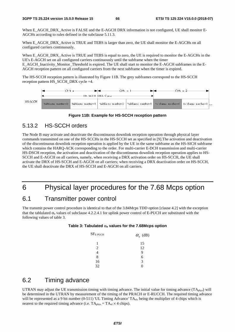
ETSI
ETSI TS 125 224 V15.0.0 (2018-07)663GPP TS 25.224 version 15.0.0 Release 15
When E_AGCH_DRX_Active is FALSE and the E-AGCH DRX information is not configured, UE shall monitor E-AGCHs according to rules defined in the subclause 5.11.3.
When E_AGCH_DRX_Active is TRUE and TEBS is larger than zero, the UE shall monitor the E-AGCHs on all configured carriers continuously.
When E_AGCH_DRX_Active is TRUE and TEBS is equal to zero, the UE is required to monitor the E-AGCHs in the UE's E-AGCH set on all configured carriers continuously until the subframe when the timer E_AGCH_Inactivity_Monitor_Threshold is expired. The UE shall start to monitor the E-AGCH subframes in the E-AGCH reception pattern on all configured carriers from the next subframe when the timer is expired.
The HS-SCCH reception pattern is illustrated by Figure 11B. The grey subframes correspond to the HS-SCCH reception pattern HS_SCCH_DRX cycle =4.
Figure 11B: Example for HS-SCCH reception pattern
5.13.2 HS-SCCH orders
The Node B may activate and deactivate the discontinuous downlink reception operation through physical layer commands transmitted on one of the HS-SCCHs in the HS-SCCH set as specified in [9].The activation and deactivation of the discontinuous downlink reception operation is applied by the UE in the same subframe as the HS-SICH subframe which contains the HARQ-ACK corresponding to the order. For multi-carrier E-DCH transmission and multi-carrier HS-DSCH reception, the activation and deactivation of the discontinuous downlink reception operation applies to HS-SCCH and E-AGCH on all carriers, namely, when receiving a DRX activation order on HS-SCCH, the UE shall activate the DRX of HS-SCCH and E-AGCH on all carriers; when receiving a DRX deactivation order on HS-SCCH, the UE shall deactivate the DRX of HS-SCCH and E-AGCH on all carriers.
6 Physical layer procedures for the 7.68 Mcps option
6.1 Transmitter power control The transmit power control procedure is identical to that of the 3.84Mcps TDD option [clause 4.2] with the exception that the tablulated αe values of subclause 4.2.2.4.1 for uplink power control of E-PUCH are substituted with the following values of table 3.
Table 3: Tabulated αe values for the 7.68Mcps option
SFE-PUCH eα (dB)
1 15 2 12 4 9 8 6 16 3 32 0
6.2 Timing advance UTRAN may adjust the UE transmission timing with timing advance. The initial value for timing advance (TAphys) will be determined in the UTRAN by measurement of the timing of the PRACH or E-RUCCH. The required timing advance will be represented as a 9 bit number (0-511) 'UL Timing Advance' TAul, being the multiplier of 4 chips which is nearest to the required timing advance (i.e. TAphys = TAul × 4 chips).
ETSI
ETSI TS 125 224 V15.0.0 (2018-07)673GPP TS 25.224 version 15.0.0 Release 15
When Timing Advance is used the UTRAN will continuously measure the timing of a transmission from the UE and send the necessary timing advance value. On receipt of this value the UE shall adjust the timing of its transmissions accordingly in steps of ±4chips. The transmission of TA values is done by means of higher layer messages. Upon receiving the TA command the UE shall adjust its transmission timing according to the timing advance command at the frame number specified by higher layer signaling. The UE is signaled the TA value in advance of the specified frame activation time to allow for local processing of the command and application of the TA adjustment on the specified frame. Node-B is also signaled the TA value and radio frame number that the TA adjustment is expected.to take place.
If TA is enabled by higher layers, after handover the UE shall transmit in the new cell with timing advance TA adjusted by the relative timing difference Δt between the new and the old cell:
TAnew = TAold + 2Δt.
6.3 Synchronisation procedures The synchronisation procedures are identical to those of the 3.84Mcps TDD option [clause 4.4].
6.4 Discontinuous transmission (DTX) procedure The discontinuous transmission procedure is identical to that of the 3.84Mcps TDD option [clause 4.5].
6.5 Downlink transmit diversity Downlink transmit diversity for PDSCH, DPCH, P-CCPCH, S-CCPCH, PICH, MICH, HS-SCCH, HS-PDSCH, E-AGCH, E-HICH and SCH is optional in UTRAN. Its support is mandatory at the UE.
6.5.1 Transmit diversity for PDSCH, DPCH, HS-SCCH, HS-PDSCH and E-AGCH
Transmit diversity for PDSCH, DPCH, HS-SCCH, HS-PDSCH and E-AGCH is identical to the 3.84Mcps TDD option [clause 4.6.1].
6.5.2 Transmit diversity for SCH and S-CCPCH
Transmit diversity for SCH and S-CCPCH is identical to the 3.84Mcps TDD option [clause 4.6.2].
6.5.3 Transmit diversity for Beacon Channels
When beacon channels use burst type 4, SCTD shall not be applied.
When beacon channels use burst type 1, Space Code Transmit Diversity (SCTD) for beacon channels may be employed optionally in the UTRAN. The support is mandatory in the UE except for the case where the UE only supports burst type 4. The use of SCTD will be indicated by higher layers. If SCTD is active within a cell:
- SCTD shall be applied to any beacon channel, and
- the maximum number KCell of midambles for burst type 1 that are supported in this cell may be 8 or 16, see [8]. The case of KCell = 4 midambles is not allowed for this burst type.
6.5.3.1 SCTD transmission scheme
The open loop downlink transmit diversity scheme for beacon channels is shown in figure 12. Channel coding, rate matching, interleaving and bit-to-symbol mapping are performed as in the non-diversity mode. In Space Code Transmit
Diversity mode the data sequence is spread with the channelisation codes )1(32
=kc and )2(32
=kc and scrambled with the cell
specific scrambling code. The spread sequence on code )2(32
=kc is then transmitted on the diversity antenna. The power
applied to each antenna shall be equal.
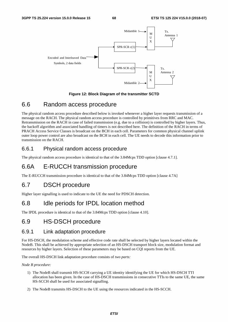
ETSI
ETSI TS 125 224 V15.0.0 (2018-07)683GPP TS 25.224 version 15.0.0 Release 15
Figure 12: Block Diagram of the transmitter SCTD
6.6 Random access procedure The physical random access procedure described below is invoked whenever a higher layer requests transmission of a message on the RACH. The physical random access procedure is controlled by primitives from RRC and MAC. Retransmission on the RACH in case of failed transmission (e.g. due to a collision) is controlled by higher layers. Thus, the backoff algorithm and associated handling of timers is not described here. The definition of the RACH in terms of PRACH Access Service Classes is broadcast on the BCH in each cell. Parameters for common physical channel uplink outer loop power control are also broadcast on the BCH in each cell. The UE needs to decode this information prior to transmission on the RACH.
6.6.1 Physical random access procedure
The physical random access procedure is identical to that of the 3.84Mcps TDD option [clause 4.7.1].
6.6A E-RUCCH transmission procedure The E-RUCCH transmission procedure is identical to that of the 3.84Mcps TDD option [clause 4.7A]
6.7 DSCH procedure Higher layer signalling is used to indicate to the UE the need for PDSCH detection.
6.8 Idle periods for IPDL location method The IPDL procedure is identical to that of the 3.84Mcps TDD option [clause 4.10].
6.9 HS-DSCH procedure
6.9.1 Link adaptation procedure
For HS-DSCH, the modulation scheme and effective code rate shall be selected by higher layers located within the NodeB. This shall be achieved by appropriate selection of an HS-DSCH transport block size, modulation format and resources by higher layers. Selection of these parameters may be based on CQI reports from the UE.
The overall HS-DSCH link adaptation procedure consists of two parts:
Node B procedure:
1) The NodeB shall transmit HS-SCCH carrying a UE identity identifying the UE for which HS-DSCH TTI allocation has been given. In the case of HS-DSCH transmissions in consecutive TTIs to the same UE, the same HS-SCCH shall be used for associated signalling.
2) The NodeB transmits HS-DSCH to the UE using the resources indicated in the HS-SCCH.
Tx.Antenna 1
Tx.Antenna 2
Encoded and Interleaved Data
Midamble 2
MUX
MUX
Midamble 1
SPR-SCR c(1)
SPR-SCR c(2)
Symbols, 2 data fields
ETSI
ETSI TS 125 224 V15.0.0 (2018-07)693GPP TS 25.224 version 15.0.0 Release 15
3) Upon receiving the HS-SICH from the respective UE, the status report (ACK/NACK and CQI) shall be passed to higher layers.
UE procedure:
1) When indicated by higher layers, the UE shall start monitoring all HS-SCCHs that are in its HS-SCCH set as signalled to it by higher layers. The information carried on the HS-SCCH is described in [8].
2) In the case that a HS-SCCH is identified to be correct by its CRC, the UE shall read the HS-PDSCHs indicated by the HS-SCCH. In the case that a HS-SCCH is identified to be incorrect, the UE shall discard the data on the HS-SCCH and return to monitoring.
3) After reading the HS-PDSCHs, the UE shall generate an ACK/NACK message and transmit this to the NodeB in the associated HS-SICH, along with the most recently derived CQI.
The mapping of HS-PDSCH channelisation code set and timeslot information carried by the HS-SCCH for a given HS-DSCH TTI is described in [9].
For a given allocation of HS-PDSCH resources to a UE for a specific HS-DSCH TTI, the following shall apply:
- If timeslot information on HS-SCCH indicates two or more timeslots, none of these timeslots shall comprise a beacon channel.
- If timeslot information on HS-SCCH indicates a single timeslot and this timeslot comprises a beacon channel then:
- The Node-B shall not indicate SF=1 for any HS-PDSCH resource.
- The set of HS-PDSCH resources allocated by the Node-B to a UE shall exclusively comprise either beacon function or non-beacon function physical channels. The Node B shall therefore not allocate both beacon function and non-beacon function physical channels within the beacon timeslot to the UE. If the HS-DSCH for a specific HS-DSCH TTI is mapped to the beacon channel, this shall be signalled using kstart = 1 and kstop = 1. For a definition of the first and last allocated channelisation code indices kstart and kstop on HS-SCCH refer to [9].
- When SCTD antenna diversity is applied to the beacon channel, then the presence of channelisation code )1(
32=kc within the channelisation code set information on HS-SCCH shall implicitly indicate the presence of
channelisation code )2(32
=kc .
6.9.2 HS-DSCH channel quality indication procedure
The HS-DSCH channel quality indication procedure is identical to that of the 3.84Mcps TDD option [clause 4.11.2].
6.10 Macro-diversity procedure The macrodiversity procedure is identical to that of the 3.84Mcps TDD option [clause 4.12].
6.11 E-DCH related procedures
6.11.1 ACK/NACK detection
The procedure for detection of ACK/NACK is identical to that of the 3.84Mcps option [subclause 4.13.1]
6.11.2 Serving and neighbour cell pathloss metric derivation
The procedure for serving and neighbour cell metric derivation is identical to that of the 3.84Mcps option [subclause 4.13.2]
6.11.3 Channelisation code hopping procedure for E-PUCH
For the 7.68Mcps option, the procedure for channelisation code hopping on E-PUCH is identical to that of the 3.84Mcps option [subclause 4.13.3] with two exceptions:
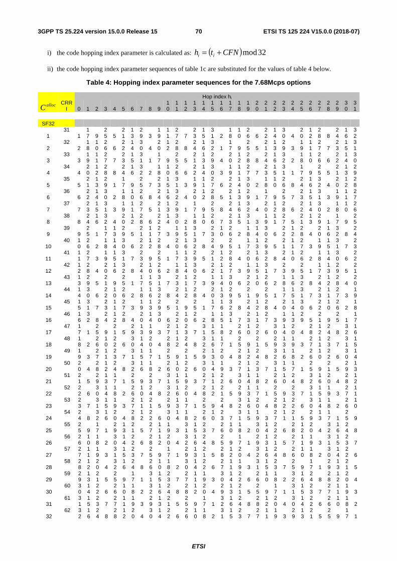
ETSI
ETSI TS 125 224 V15.0.0 (2018-07)703GPP TS 25.224 version 15.0.0 Release 15
i) the code hopping index parameter is calculated as: ( ) 32modCFNth ii +=
ii) the code hopping index parameter sequences of table 1c are substituted for the values of table 4 below.
Table 4: Hopping index parameter sequences for the 7.68Mcps options
Hop index hi
allocC CRR
I 0 1 2 3 4 5 6 7 8 9 10
11
12
13
14
15
16
17
18
19
20
21
22
23
24
25
26
27
28
29
30
31
SF32
1 31
1 17 9
25 5
21
13
29 3
19
11
27 7
23
15
31 2
18
10
26 6
22
14
30 4
20
12
28 8
24
16
32
2 32
2 18
10
26 6
22
14
30 4
20
12
28 8
24
16
32 1
17 9
25 5
21
13
29 3
19
11
27 7
23
15
31
3 33
3 19
11
27 7
23
15
31 1
17 9
25 5
21
13
29 4
20
12
28 8
24
16
32 2
18
10
26 6
22
14
30
4 34
4 20
12
28 8
24
16
32 2
18
10
26 6
22
14
30 3
19
11
27 7
23
15
31 1
17 9
25 5
21
13
29
5 35
5 21
13
29 1
17 9
25 7
23
15
31 3
19
11
27 6
22
14
30 2
18
10
26 8
24
16
32 4
20
12
28
6 36
6 22
14
30 2
18
10
26 8
24
16
32 4
20
12
28 5
21
13
29 1
17 9
25 7
23
15
31 3
19
11
27
7 37
7 23
15
31 3
19
11
27 5
21
13
29 1
17 9
25 8
24
16
32 4
20
12
28 6
22
14
30 2
18
10
26
8 38
8 24
16
32 4
20
12
28 6
22
14
30 2
18
10
26 7
23
15
31 3
19
11
27 5
21
13
29 1
17 9
25
9 39
9 25 1
17
13
29 5
21
11
27 3
19
15
31 7
23
10
26 2
18
14
30 6
22
12
28 4
20
16
32 8
24
10 40 1
0 26 2
18
14
30 6
22
12
28 4
20
16
32 8
24 9
25 1
17
13
29 5
21
11
27 3
19
15
31 7
23
11 41 1
1 27 3
19
15
31 7
23 9
25 1
17
13
29 5
21
12
28 4
20
16
32 8
24
10
26 2
18
14
30 6
22
12 42 1
2 28 4
20
16
32 8
24
10
26 2
18
14
30 6
22
11
27 3
19
15
31 7
23 9
25 1
17
13
29 5
21
13 43 1
3 29 5
21 9
25 1
17
15
31 7
23
11
27 3
19
14
30 6
22
10
26 2
18
16
32 8
24
12
28 4
20
14 44 1
4 30 6
22
10
26 2
18
16
32 8
24
12
28 4
20
13
29 5
21 9
25 1
17
15
31 7
23
11
27 3
19
15 45 1
5 31 7
23
11
27 3
19
13
29 5
21 9
25 1
17
16
32 8
24
12
28 4
20
14
30 6
22
10
26 2
18
16 46 1
6 32 8
24
12
28 4
20
14
30 6
22
10
26 2
18
15
31 7
23
11
27 3
19
13
29 5
21 9
25 1
17
17 47 1
7 1 25 9
21 5
29
13
19 3
27
11
23 7
31
15
18 2
26
10
22 6
30
14
20 4
28
12
24 8
32
16
18 48 1
8 2 26
10
22 6
30
14
20 4
28
12
24 8
32
16
17 1
25 9
21 5
29
13
19 3
27
11
23 7
31
15
19 49 1
9 3 27
11
23 7
31
15
17 1
25 9
21 5
29
13
20 4
28
12
24 8
32
16
18 2
26
10
22 6
30
14
20 50 2
0 4 28
12
24 8
32
16
18 2
26
10
22 6
30
14
19 3
27
11
23 7
31
15
17 1
25 9
21 5
29
13
21 51 2
1 5 29
13
17 1
25 9
23 7
31
15
19 3
27
11
22 6
30
14
18 2
26
10
24 8
32
16
20 4
28
12
22 52 2
2 6 30
14
18 2
26
10
24 8
32
16
20 4
28
12
21 5
29
13
17 1
25 9
23 7
31
15
19 3
27
11
23 53 2
3 7 31
15
19 3
27
11
21 5
29
13
17 1
25 9
24 8
32
16
20 4
28
12
22 6
30
14
18 2
26
10
24 54 2
4 8 32
16
20 4
28
12
22 6
30
14
18 2
26
10
23 7
31
15
19 3
27
11
21 5
29
13
17 1
25 9
25 55 2
5 9 17 1
29
13
21 5
27
11
19 3
31
15
23 7
26
10
18 2
30
14
22 6
28
12
20 4
32
16
24 8
26 56 2
6 10
18 2
30
14
22 6
28
12
20 4
32
16
24 8
25 9
17 1
29
13
21 5
27
11
19 3
31
15
23 7
27 57 2
7 11
19 3
31
15
23 7
25 9
17 1
29
13
21 5
28
12
20 4
32
16
24 8
26
10
18 2
30
14
22 6
28 58 2
8 12
20 4
32
16
24 8
26
10
18 2
30
14
22 6
27
11
19 3
31
15
23 7
25 9
17 1
29
13
21 5
29 59 2
9 13
21 5
25 9
17 1
31
15
23 7
27
11
19 3
30
14
22 6
26
10
18 2
32
16
24 8
28
12
20 4
30 60 3
0 14
22 6
26
10
18 2
32
16
24 8
28
12
20 4
29
13
21 5
25 9
17 1
31
15
23 7
27
11
19 3
31 61 3
1 15
23 7
27
11
19 3
29
13
21 5
25 9
17 1
32
16
24 8
28
12
20 4
30
14
22 6
26
10
18 2
32 62 3
2 16
24 8
28
12
20 4
30
14
22 6
26
10
18 2
31
15
23 7
27
11
19 3
29
13
21 5
25 9
17 1
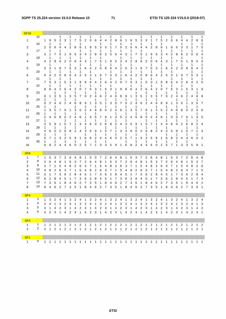
ETSI
ETSI TS 125 224 V15.0.0 (2018-07)713GPP TS 25.224 version 15.0.0 Release 15
SF16
1 15
1 9 5 13 3
11 7
15 2
10 6
14 4
12 8
16 1 9 5
13 3
11 7
15 2
10 6
14 4
12 8
16
2 16
2 10 6
14 4
12 8
16 1 9 5
13 3
11 7
15 2
10 6
14 4
12 8
16 1 9 5
13 3
11 7
15
3 17
3 11 7
15 1 9 5
13 4
12 8
16 2
10 6
14 3
11 7
15 1 9 5
13 4
12 8
16 2
10 6
14
4 18
4 12 8
16 2
10 6
14 3
11 7
15 1 9 5
13 4
12 8
16 2
10 6
14 3
11 7
15 1 9 5
13
5 19
5 13 1 9 7
15 3
11 6
14 2
10 8
16 4
12 5
13 1 9 7
15 3
11 6
14 2
10 8
16 4
12
6 20
6 14 2
10 8
16 4
12 5
13 1 9 7
15 3
11 6
14 2
10 8
16 4
12 5
13 1 9 7
15 3
11
7 21
7 15 3
11 5
13 1 9 8
16 4
12 6
14 2
10 7
15 3
11 5
13 1 9 8
16 4
12 6
14 2
10
8 22
8 16 4
12 6
14 2
10 7
15 3
11 5
13 1 9 8
16 4
12 6
14 2
10 7
15 3
11 5
13 1 9
9 23
9 1 13 5
11 3
15 7
10 2
14 6
12 4
16 8 9 1
13 5
11 3
15 7
10 2
14 6
12 4
16 8
10 24 1
0 2 14 6
12 4
16 8 9 1
13 5
11 3
15 7
10 2
14 6
12 4
16 8 9 1
13 5
11 3
15 7
11 25 1
1 3 15 7 9 1
13 5
12 4
16 8
10 2
14 6
11 3
15 7 9 1
13 5
12 4
16 8
10 2
14 6
12 26 1
2 4 16 8
10 2
14 6
11 3
15 7 9 1
13 5
12 4
16 8
10 2
14 6
11 3
15 7 9 1
13 5
13 27 1
3 5 9 1 15 7
11 3
14 6
10 2
16 8
12 4
13 5 9 1
15 7
11 3
14 6
10 2
16 8
12 4
14 28 1
4 6 10 2
16 8
12 4
13 5 9 1
15 7
11 3
14 6
10 2
16 8
12 4
13 5 9 1
15 7
11 3
15 29 1
5 7 11 3
13 5 9 1
16 8
12 4
14 6
10 2
15 7
11 3
13 5 9 1
16 8
12 4
14 6
10 2
16 30 1
6 8 12 4
14 6
10 2
15 7
11 3
13 5 9 1
16 8
12 4
14 6
10 2
15 7
11 3
13 5 9 1
SF8
1 7 1 5 3 7 2 6 4 8 1 5 3 7 2 6 4 8 1 5 3 7 2 6 4 8 1 5 3 7 2 6 4 8 2 8 2 6 4 8 1 5 3 7 2 6 4 8 1 5 3 7 2 6 4 8 1 5 3 7 2 6 4 8 1 5 3 7 3 9 3 7 1 5 4 8 2 6 3 7 1 5 4 8 2 6 3 7 1 5 4 8 2 6 3 7 1 5 4 8 2 6 4 10 4 8 2 6 3 7 1 5 4 8 2 6 3 7 1 5 4 8 2 6 3 7 1 5 4 8 2 6 3 7 1 5 5 11 5 1 7 3 6 2 8 4 5 1 7 3 6 2 8 4 5 1 7 3 6 2 8 4 5 1 7 3 6 2 8 4 6 12 6 2 8 4 5 1 7 3 6 2 8 4 5 1 7 3 6 2 8 4 5 1 7 3 6 2 8 4 5 1 7 3 7 13 7 3 5 1 8 4 6 2 7 3 5 1 8 4 6 2 7 3 5 1 8 4 6 2 7 3 5 1 8 4 6 2 8 14 8 4 6 2 7 3 5 1 8 4 6 2 7 3 5 1 8 4 6 2 7 3 5 1 8 4 6 2 7 3 5 1
SF4 1 3 1 3 2 4 1 3 2 4 1 3 2 4 1 3 2 4 1 3 2 4 1 3 2 4 1 3 2 4 1 3 2 4 2 4 2 4 1 3 2 4 1 3 2 4 1 3 2 4 1 3 2 4 1 3 2 4 1 3 2 4 1 3 2 4 1 3 3 5 3 1 4 2 3 1 4 2 3 1 4 2 3 1 4 2 3 1 4 2 3 1 4 2 3 1 4 2 3 1 4 2 4 6 4 2 3 1 4 2 3 1 4 2 3 1 4 2 3 1 4 2 3 1 4 2 3 1 4 2 3 1 4 2 3 1
SF2 1 1 1 2 1 2 1 2 1 2 1 2 1 2 1 2 1 2 1 2 1 2 1 2 1 2 1 2 1 2 1 2 1 2 2 2 2 1 2 1 2 1 2 1 2 1 2 1 2 1 2 1 2 1 2 1 2 1 2 1 2 1 2 1 2 1 2 1
SF1 1 0 1 1 1 1 1 1 1 1 1 1 1 1 1 1 1 1 1 1 1 1 1 1 1 1 1 1 1 1 1 1 1 1
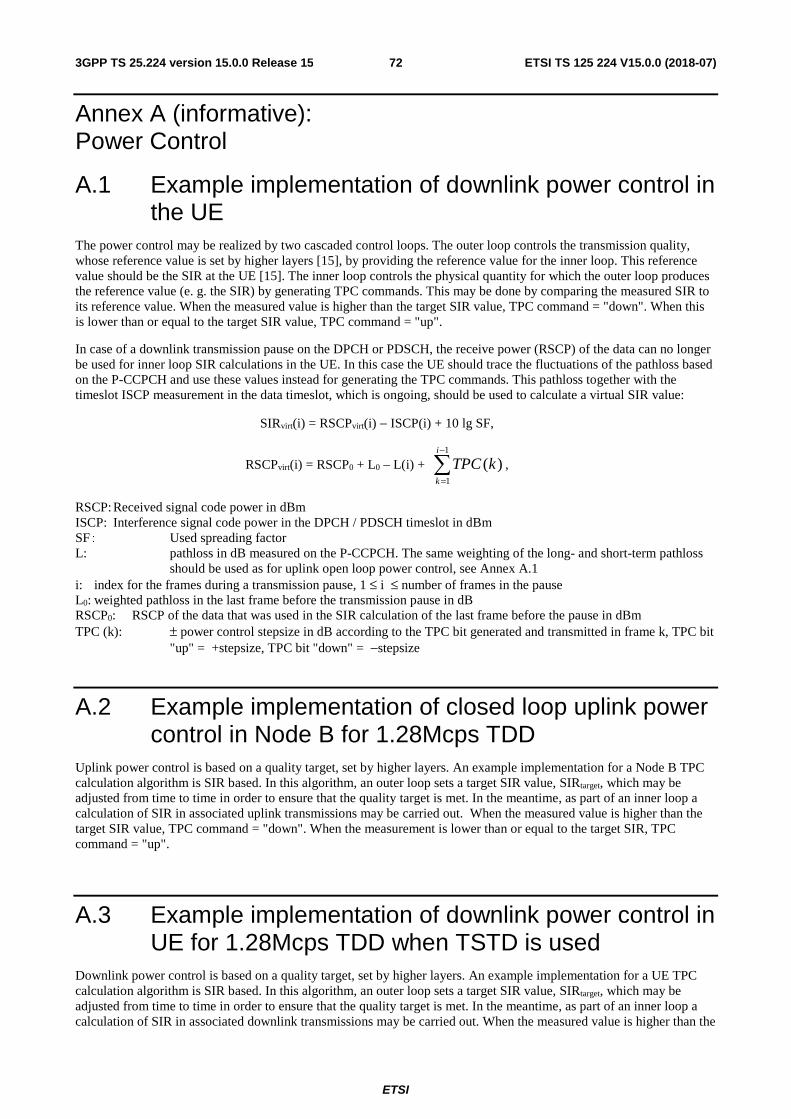
ETSI
ETSI TS 125 224 V15.0.0 (2018-07)723GPP TS 25.224 version 15.0.0 Release 15
Annex A (informative): Power Control
A.1 Example implementation of downlink power control in the UE
The power control may be realized by two cascaded control loops. The outer loop controls the transmission quality, whose reference value is set by higher layers [15], by providing the reference value for the inner loop. This reference value should be the SIR at the UE [15]. The inner loop controls the physical quantity for which the outer loop produces the reference value (e. g. the SIR) by generating TPC commands. This may be done by comparing the measured SIR to its reference value. When the measured value is higher than the target SIR value, TPC command = "down". When this is lower than or equal to the target SIR value, TPC command = "up".
In case of a downlink transmission pause on the DPCH or PDSCH, the receive power (RSCP) of the data can no longer be used for inner loop SIR calculations in the UE. In this case the UE should trace the fluctuations of the pathloss based on the P-CCPCH and use these values instead for generating the TPC commands. This pathloss together with the timeslot ISCP measurement in the data timeslot, which is ongoing, should be used to calculate a virtual SIR value:
SIRvirt(i) = RSCPvirt(i) − ISCP(i) + 10 lg SF,
RSCPvirt(i) = RSCP0 + L0 – L(i) + ,
RSCP: Received signal code power in dBm ISCP: Interference signal code power in the DPCH / PDSCH timeslot in dBm SF: Used spreading factor L: pathloss in dB measured on the P-CCPCH. The same weighting of the long- and short-term pathloss
should be used as for uplink open loop power control, see Annex A.1 i: index for the frames during a transmission pause, 1 ≤ i ≤ number of frames in the pause L0: weighted pathloss in the last frame before the transmission pause in dB RSCP0: RSCP of the data that was used in the SIR calculation of the last frame before the pause in dBm TPC (k): ± power control stepsize in dB according to the TPC bit generated and transmitted in frame k, TPC bit
"up" = +stepsize, TPC bit "down" = −stepsize
A.2 Example implementation of closed loop uplink power control in Node B for 1.28Mcps TDD
Uplink power control is based on a quality target, set by higher layers. An example implementation for a Node B TPC calculation algorithm is SIR based. In this algorithm, an outer loop sets a target SIR value, SIRtarget, which may be adjusted from time to time in order to ensure that the quality target is met. In the meantime, as part of an inner loop a calculation of SIR in associated uplink transmissions may be carried out. When the measured value is higher than the target SIR value, TPC command = "down". When the measurement is lower than or equal to the target SIR, TPC command = "up".
A.3 Example implementation of downlink power control in UE for 1.28Mcps TDD when TSTD is used
Downlink power control is based on a quality target, set by higher layers. An example implementation for a UE TPC calculation algorithm is SIR based. In this algorithm, an outer loop sets a target SIR value, SIRtarget, which may be adjusted from time to time in order to ensure that the quality target is met. In the meantime, as part of an inner loop a calculation of SIR in associated downlink transmissions may be carried out. When the measured value is higher than the
−
=
1
1
)(i
k
kTPC
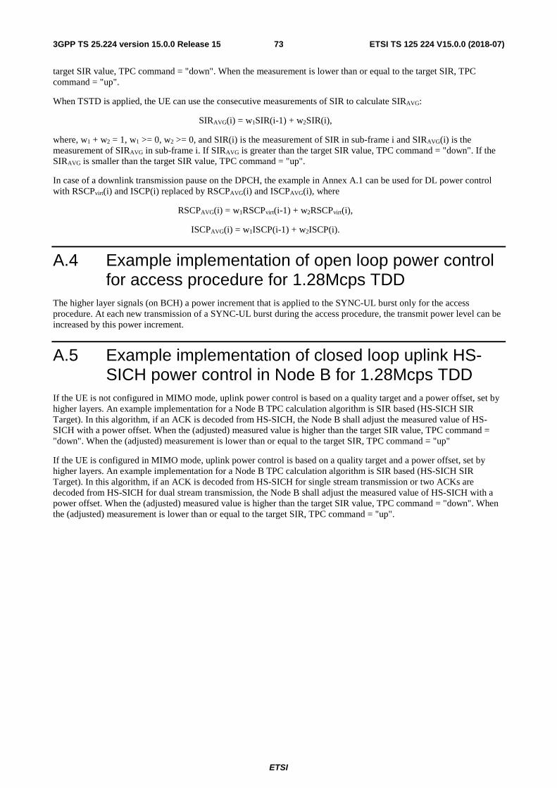
ETSI
ETSI TS 125 224 V15.0.0 (2018-07)733GPP TS 25.224 version 15.0.0 Release 15
target SIR value, TPC command = "down". When the measurement is lower than or equal to the target SIR, TPC command = "up".
When TSTD is applied, the UE can use the consecutive measurements of SIR to calculate SIRAVG:
SIRAVG(i) = w1SIR(i-1) + w2SIR(i),
where, w1 + w2 = 1, w1 >= 0, w2 >= 0, and SIR(i) is the measurement of SIR in sub-frame i and SIRAVG(i) is the measurement of SIRAVG in sub-frame i. If SIRAVG is greater than the target SIR value, TPC command = "down". If the SIRAVG is smaller than the target SIR value, TPC command = "up".
In case of a downlink transmission pause on the DPCH, the example in Annex A.1 can be used for DL power control with RSCPvirt(i) and ISCP(i) replaced by RSCPAVG(i) and ISCPAVG(i), where
RSCPAVG(i) = w1RSCPvirt(i-1) + w2RSCPvirt(i),
ISCPAVG(i) = w1ISCP(i-1) + w2ISCP(i).
A.4 Example implementation of open loop power control for access procedure for 1.28Mcps TDD
The higher layer signals (on BCH) a power increment that is applied to the SYNC-UL burst only for the access procedure. At each new transmission of a SYNC-UL burst during the access procedure, the transmit power level can be increased by this power increment.
A.5 Example implementation of closed loop uplink HS-SICH power control in Node B for 1.28Mcps TDD
If the UE is not configured in MIMO mode, uplink power control is based on a quality target and a power offset, set by higher layers. An example implementation for a Node B TPC calculation algorithm is SIR based (HS-SICH SIR Target). In this algorithm, if an ACK is decoded from HS-SICH, the Node B shall adjust the measured value of HS-SICH with a power offset. When the (adjusted) measured value is higher than the target SIR value, TPC command = "down". When the (adjusted) measurement is lower than or equal to the target SIR, TPC command = "up"
If the UE is configured in MIMO mode, uplink power control is based on a quality target and a power offset, set by higher layers. An example implementation for a Node B TPC calculation algorithm is SIR based (HS-SICH SIR Target). In this algorithm, if an ACK is decoded from HS-SICH for single stream transmission or two ACKs are decoded from HS-SICH for dual stream transmission, the Node B shall adjust the measured value of HS-SICH with a power offset. When the (adjusted) measured value is higher than the target SIR value, TPC command = "down". When the (adjusted) measurement is lower than or equal to the target SIR, TPC command = "up".
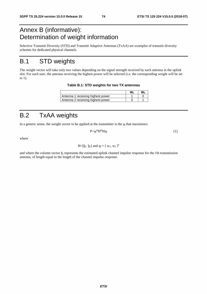
ETSI
ETSI TS 125 224 V15.0.0 (2018-07)743GPP TS 25.224 version 15.0.0 Release 15
Annex B (informative): Determination of weight information Selective Transmit Diversity (STD) and Transmit Adaptive Antennas (TxAA) are examples of transmit diversity schemes for dedicated physical channels.
B.1 STD weights The weight vector will take only two values depending on the signal strength received by each antenna in the uplink slot. For each user, the antenna receiving the highest power will be selected (i.e. the corresponding weight will be set to 1).
Table B.1: STD weights for two TX antennas
W1 W2 Antenna 1 receiving highest power 1 0 Antenna 2 receiving highest power 0 1
B.2 TxAA weights In a generic sense, the weight vector to be applied at the transmitter is the w that maximises:
P=wHHHHw (1)
where
H=[h1 h2] and w = [ w1, w2 ]T
and where the column vector hi represents the estimated uplink channel impulse response for the i'th transmission antenna, of length equal to the length of the channel impulse response.
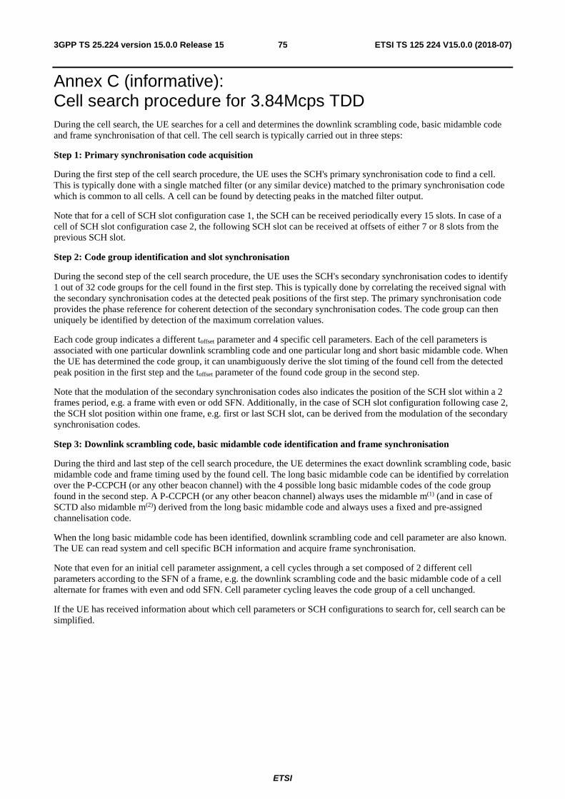
ETSI
ETSI TS 125 224 V15.0.0 (2018-07)753GPP TS 25.224 version 15.0.0 Release 15
Annex C (informative): Cell search procedure for 3.84Mcps TDD During the cell search, the UE searches for a cell and determines the downlink scrambling code, basic midamble code and frame synchronisation of that cell. The cell search is typically carried out in three steps:
Step 1: Primary synchronisation code acquisition
During the first step of the cell search procedure, the UE uses the SCH's primary synchronisation code to find a cell. This is typically done with a single matched filter (or any similar device) matched to the primary synchronisation code which is common to all cells. A cell can be found by detecting peaks in the matched filter output.
Note that for a cell of SCH slot configuration case 1, the SCH can be received periodically every 15 slots. In case of a cell of SCH slot configuration case 2, the following SCH slot can be received at offsets of either 7 or 8 slots from the previous SCH slot.
Step 2: Code group identification and slot synchronisation
During the second step of the cell search procedure, the UE uses the SCH's secondary synchronisation codes to identify 1 out of 32 code groups for the cell found in the first step. This is typically done by correlating the received signal with the secondary synchronisation codes at the detected peak positions of the first step. The primary synchronisation code provides the phase reference for coherent detection of the secondary synchronisation codes. The code group can then uniquely be identified by detection of the maximum correlation values.
Each code group indicates a different toffset parameter and 4 specific cell parameters. Each of the cell parameters is associated with one particular downlink scrambling code and one particular long and short basic midamble code. When the UE has determined the code group, it can unambiguously derive the slot timing of the found cell from the detected peak position in the first step and the toffset parameter of the found code group in the second step.
Note that the modulation of the secondary synchronisation codes also indicates the position of the SCH slot within a 2 frames period, e.g. a frame with even or odd SFN. Additionally, in the case of SCH slot configuration following case 2, the SCH slot position within one frame, e.g. first or last SCH slot, can be derived from the modulation of the secondary synchronisation codes.
Step 3: Downlink scrambling code, basic midamble code identification and frame synchronisation
During the third and last step of the cell search procedure, the UE determines the exact downlink scrambling code, basic midamble code and frame timing used by the found cell. The long basic midamble code can be identified by correlation over the P-CCPCH (or any other beacon channel) with the 4 possible long basic midamble codes of the code group found in the second step. A P-CCPCH (or any other beacon channel) always uses the midamble m(1) (and in case of SCTD also midamble m(2)) derived from the long basic midamble code and always uses a fixed and pre-assigned channelisation code.
When the long basic midamble code has been identified, downlink scrambling code and cell parameter are also known. The UE can read system and cell specific BCH information and acquire frame synchronisation.
Note that even for an initial cell parameter assignment, a cell cycles through a set composed of 2 different cell parameters according to the SFN of a frame, e.g. the downlink scrambling code and the basic midamble code of a cell alternate for frames with even and odd SFN. Cell parameter cycling leaves the code group of a cell unchanged.
If the UE has received information about which cell parameters or SCH configurations to search for, cell search can be simplified.
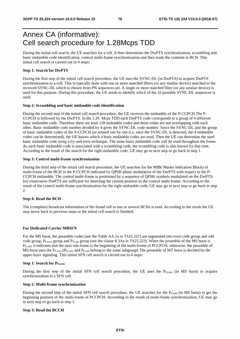
ETSI
ETSI TS 125 224 V15.0.0 (2018-07)763GPP TS 25.224 version 15.0.0 Release 15
Annex CA (informative): Cell search procedure for 1.28Mcps TDD During the initial cell search, the UE searches for a cell. It then determines the DwPTS synchronization, scrambling and basic midamble code identification, control multi-frame synchronisation and then reads the contents in BCH. This initial cell search is carried out in 4 steps:
Step 1: Search for DwPTS
During the first step of the initial cell search procedure, the UE uses the SYNC-DL (in DwPTS) to acquire DwPTS synchronization to a cell. This is typically done with one or more matched filters (or any similar device) matched to the received SYNC-DL which is chosen from PN sequences set. A single or more matched filter (or any similar device) is used for this purpose. During this procedure, the UE needs to identify which of the 32 possible SYNC-DL sequences is used.
Step 2: Scrambling and basic midamble code identification
During the second step of the initial cell search procedure, the UE receives the midamble of the P-CCPCH.The P-CCPCH is followed by the DwPTS. In the 1.28 Mcps TDD each DwPTS code corresponds to a group of 4 different basic midamble code. Therefore there are total 128 midamble codes and these codes are not overlapping with each other. Basic midamble code number divided by 4 gives the SYNC-DL code number. Since the SYNC-DL and the group of basic midamble codes of the P-CCPCH are related one by one (i.e, once the SYNC-DL is detected, the 4 midamble codes can be determined), the UE knows which 4 basic midamble codes are used. Then the UE can determine the used basic midamble code using a try and error technique. The same basic midamble code will be used throughout the frame. As each basic midamble code is associated with a scrambling code, the scrambling code is also known by that time. According to the result of the search for the right midamble code, UE may go to next step or go back to step 1.
Step 3: Control multi-frame synchronisation
During the third step of the initial cell search procedure, the UE searches for the MIB( Master Indication Block) of multi-frame of the BCH in the P-CCPCH indicated by QPSK phase modulation of the DwPTS with respect to the P-CCPCH midamble. The control multi-frame is positioned by a sequence of QPSK symbols modulated on the DwPTS. [n] consecutive DwPTS are sufficient for detecting the current position in the control multi-frame. According to the result of the control multi-frame synchronisation for the right midamble code, UE may go to next step or go back to step 2.
Step 4: Read the BCH
The (complete) broadcast information of the found cell in one or several BCHs is read. According to the result the UE may move back to previous steps or the initial cell search is finished.
For Dedicated Carrier MBSFN
For the MS burst, the preamble codes (see the Table AA.1a in TS25.221) are segmented into even code group and odd code group, PP,even group and PP,odd group (see the clause 8.3Aa in TS25.223). When the preamble of the MS burst is PP,odd, it indicates that the next sub-frame is the beginning of the multi-frame of PCCPCH; otherwise, the preamble of MS burst uses the PP,even (PP,even and PP,odd belong to the same subgroup). The preamble of MT burst is decided by the upper-layer signaling. This initial SFN cell search is carried out in 4 steps:
Step 1: Search for PP,even
During the first step of the initial SFN cell search procedure, the UE uses the PP,even (in MS burst) to acquire synchronization to a SFN cell.
Step 2: Multi-frame synchronization
During the second step of the initial SFN cell search procedure, the UE searches for the PP,odd (in MS burst) to get the beginning position of the multi-frame of PCCPCH. According to the result of multi-frame synchronization, UE may go to next step or go back to step 1.
Step 3: Read the BCCH

ETSI
ETSI TS 125 224 V15.0.0 (2018-07)773GPP TS 25.224 version 15.0.0 Release 15
The UE reads the MIB (Master Indication Block) of multi-frame P-CCPCHs in the BCH and gets the system information of the found SFN cell. According to the result of reading the BCCH, UE may go to next step or go back to step 2.
Step 4: Read the MCCH
The UE reads the MCCH indicated by the BCCH information. According to the result the UE may move back to previous steps or the initial cell search is finished.
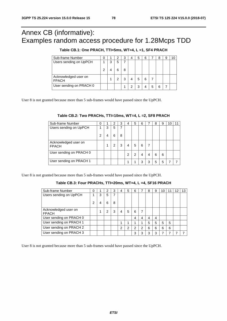
ETSI
ETSI TS 125 224 V15.0.0 (2018-07)783GPP TS 25.224 version 15.0.0 Release 15
Annex CB (informative): Examples random access procedure for 1.28Mcps TDD
Table CB.1: One PRACH, TTI=5ms, WT=4, L =1, SF4 PRACH
Sub-frame Number 0 1 2 3 4 5 6 7 8 9 10 Users sending on UpPCH 1
2
3
4
5
6
7
8
Acknowledged user on FPACH 1 2 3 4 5 6 7
User sending on PRACH 0 1 2 3 4 5 6 7
User 8 is not granted because more than 5 sub-frames would have passed since the UpPCH.
Table CB.2: Two PRACHs, TTI=10ms, WT=4, L =2, SF8 PRACH
Sub-frame Number 0 1 2 3 4 5 6 7 8 9 10 11 Users sending on UpPCH 1
2
3
4
5
6
7
8
Acknowledged user on FPACH 1 2 3 4 5 6 7
User sending on PRACH 0 2 2 4 4 6 6
User sending on PRACH 1 1 1 3 3 5 5 7 7
User 8 is not granted because more than 5 sub-frames would have passed since the UpPCH.
Table CB.3: Four PRACHs, TTI=20ms, WT=4, L =4, SF16 PRACH
Sub-frame Number 0 1 2 3 4 5 6 7 8 9 10 11 12 13 Users sending on UpPCH 1
2
3
4
5
6
7
8
Acknowledged user on FPACH 1 2 3 4 5 6 7
User sending on PRACH 0 4 4 4 4 User sending on PRACH 1 1 1 1 1 5 5 5 5 User sending on PRACH 2 2 2 2 2 6 6 6 6 User sending on PRACH 3 3 3 3 3 7 7 7 7
User 8 is not granted because more than 5 sub-frames would have passed since the UpPCH.
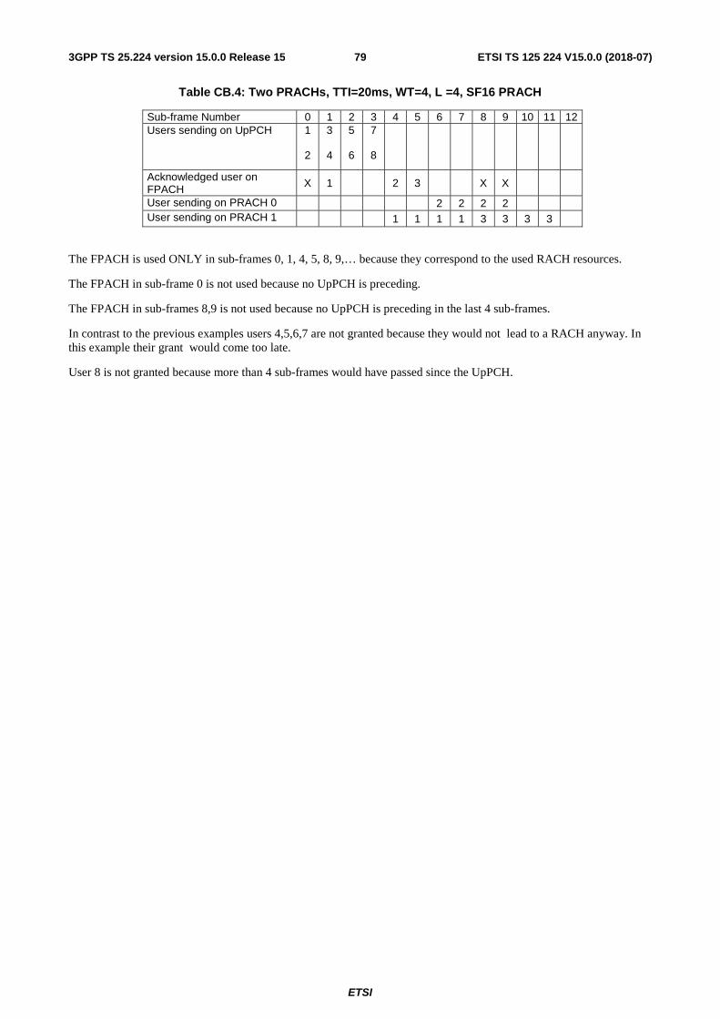
ETSI
ETSI TS 125 224 V15.0.0 (2018-07)793GPP TS 25.224 version 15.0.0 Release 15
Table CB.4: Two PRACHs, TTI=20ms, WT=4, L =4, SF16 PRACH
Sub-frame Number 0 1 2 3 4 5 6 7 8 9 10 11 12 Users sending on UpPCH 1
2
3
4
5
6
7
8
Acknowledged user on FPACH X 1 2 3 X X
User sending on PRACH 0 2 2 2 2 User sending on PRACH 1 1 1 1 1 3 3 3 3
The FPACH is used ONLY in sub-frames 0, 1, 4, 5, 8, 9,… because they correspond to the used RACH resources.
The FPACH in sub-frame 0 is not used because no UpPCH is preceding.
The FPACH in sub-frames 8,9 is not used because no UpPCH is preceding in the last 4 sub-frames.
In contrast to the previous examples users 4,5,6,7 are not granted because they would not lead to a RACH anyway. In this example their grant would come too late.
User 8 is not granted because more than 4 sub-frames would have passed since the UpPCH.

ETSI
ETSI TS 125 224 V15.0.0 (2018-07)803GPP TS 25.224 version 15.0.0 Release 15
Annex D (informative): Change history
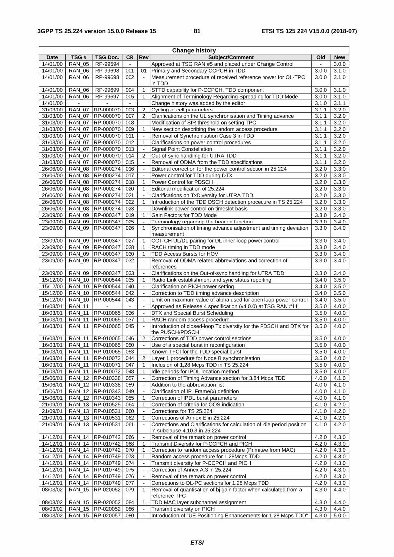
ETSI
ETSI TS 125 224 V15.0.0 (2018-07)813GPP TS 25.224 version 15.0.0 Release 15
Change history Date TSG # TSG Doc. CR Rev Subject/Comment Old New
14/01/00 RAN_05 RP-99594 - Approved at TSG RAN #5 and placed under Change Control - 3.0.0 14/01/00 RAN_06 RP-99698 001 01 Primary and Secondary CCPCH in TDD 3.0.0 3.1.0 14/01/00 RAN_06 RP-99698 002 - Measurement procedure of received reference power for OL-TPC
in TDD 3.0.0 3.1.0
14/01/00 RAN_06 RP-99699 004 1 STTD capability for P-CCPCH, TDD component 3.0.0 3.1.0 14/01/00 RAN_06 RP-99697 005 1 Alignment of Terminology Regarding Spreading for TDD Mode 3.0.0 3.1.0 14/01/00 - - - Change history was added by the editor 3.1.0 3.1.1 31/03/00 RAN_07 RP-000070 003 2 Cycling of cell parameters 3.1.1 3.2.0 31/03/00 RAN_07 RP-000070 007 2 Clarifications on the UL synchronisation and Timing advance 3.1.1 3.2.0 31/03/00 RAN_07 RP-000070 008 - Modification of SIR threshold on setting TPC 3.1.1 3.2.0 31/03/00 RAN_07 RP-000070 009 1 New section describing the random access procedure 3.1.1 3.2.0 31/03/00 RAN_07 RP-000070 011 - Removal of Synchronisation Case 3 in TDD 3.1.1 3.2.0 31/03/00 RAN_07 RP-000070 012 1 Clarifications on power control procedures 3.1.1 3.2.0 31/03/00 RAN_07 RP-000070 013 - Signal Point Constellation 3.1.1 3.2.0 31/03/00 RAN_07 RP-000070 014 2 Out-of-sync handling for UTRA TDD 3.1.1 3.2.0 31/03/00 RAN_07 RP-000070 015 - Removal of ODMA from the TDD specifications 3.1.1 3.2.0 26/06/00 RAN_08 RP-000274 016 - Editorial correction for the power control section in 25.224 3.2.0 3.3.0 26/06/00 RAN_08 RP-000274 017 - Power control for TDD during DTX 3.2.0 3.3.0 26/06/00 RAN_08 RP-000274 018 1 Power Control for PDSCH 3.2.0 3.3.0 26/06/00 RAN_08 RP-000274 020 1 Editorial modification of 25.224 3.2.0 3.3.0 26/06/00 RAN_08 RP-000274 021 - Clarifications on TxDiversity for UTRA TDD 3.2.0 3.3.0 26/06/00 RAN_08 RP-000274 022 1 Introduction of the TDD DSCH detection procedure in TS 25.224 3.2.0 3.3.0 26/06/00 RAN_08 RP-000274 023 - Downlink power control on timeslot basis 3.2.0 3.3.0 23/09/00 RAN_09 RP-000347 019 1 Gain Factors for TDD Mode 3.3.0 3.4.0 23/09/00 RAN_09 RP-000347 025 - Terminology regarding the beacon function 3.3.0 3.4.0 23/09/00 RAN_09 RP-000347 026 1 Synchronisation of timing advance adjustment and timing deviation
measurement 3.3.0 3.4.0
23/09/00 RAN_09 RP-000347 027 1 CCTrCH UL/DL pairing for DL inner loop power control 3.3.0 3.4.0 23/09/00 RAN_09 RP-000347 028 1 RACH timing in TDD mode 3.3.0 3.4.0 23/09/00 RAN_09 RP-000347 030 1 TDD Access Bursts for HOV 3.3.0 3.4.0 23/09/00 RAN_09 RP-000347 032 - Removal of ODMA related abbreviations and correction of
references 3.3.0 3.4.0
23/09/00 RAN_09 RP-000347 033 - Clarifications on the Out-of-sync handling for UTRA TDD 3.3.0 3.4.0 15/12/00 RAN_10 RP-000544 035 1 Radio Link establishment and sync status reporting 3.4.0 3.5.0 15/12/00 RAN_10 RP-000544 040 - Clarification on PICH power setting 3.4.0 3.5.0 15/12/00 RAN_10 RP-000544 042 - Correction to TDD timing advance description 3.4.0 3.5.0 15/12/00 RAN_10 RP-000544 043 - Limit on maximum value of alpha used for open loop power control 3.4.0 3.5.0 16/03/01 RAN_11 - - - Approved as Release 4 specification (v4.0.0) at TSG RAN #11 3.5.0 4.0.0 16/03/01 RAN_11 RP-010065 036 - DTX and Special Burst Scheduling 3.5.0 4.0.0 16/03/01 RAN_11 RP-010065 037 1 RACH random access procedure 3.5.0 4.0.0 16/03/01 RAN_11 RP-010065 045 - Introduction of closed-loop Tx diversity for the PDSCH and DTX for
the PUSCH/PDSCH 3.5.0 4.0.0
16/03/01 RAN_11 RP-010065 046 2 Corrections of TDD power control sections 3.5.0 4.0.0 16/03/01 RAN_11 RP-010065 050 - Use of a special burst in reconfiguration 3.5.0 4.0.0 16/03/01 RAN_11 RP-010065 053 - Known TFCI for the TDD special burst 3.5.0 4.0.0 16/03/01 RAN_11 RP-010073 044 2 Layer 1 procedure for Node B synchronisation 3.5.0 4.0.0 16/03/01 RAN_11 RP-010071 047 1 Inclusion of 1,28 Mcps TDD in TS 25.224 3.5.0 4.0.0 16/03/01 RAN_11 RP-010072 048 1 Idle periods for IPDL location method 3.5.0 4.0.0 15/06/01 RAN_12 RP-010338 057 - Correction of Timing Advance section for 3.84 Mcps TDD 4.0.0 4.1.0 15/06/01 RAN_12 RP-010338 059 - Addition to the abbreviation list 4.0.0 4.1.0 15/06/01 RAN_12 RP-010343 049 - Clarification of IP_Frame(x) definition 4.0.0 4.1.0 15/06/01 RAN_12 RP-010343 055 1 Correction of IPDL burst parameters 4.0.0 4.1.0 21/09/01 RAN_13 RP-010525 064 1 Correction of criteria for OOS indication 4.1.0 4.2.0 21/09/01 RAN_13 RP-010531 060 - Corrections for TS 25.224 4.1.0 4.2.0 21/09/01 RAN_13 RP-010531 062 1 Corrections of Annex E in 25.224 4.1.0 4.2.0 21/09/01 RAN_13 RP-010531 061 - Corrections and Clarifications for calculation of idle period position
in subclause 4.10.3 in 25.224 4.1.0 4.2.0
14/12/01 RAN_14 RP-010742 066 - Removal of the remark on power control 4.2.0 4.3.0 14/12/01 RAN_14 RP-010742 068 1 Transmit Diversity for P-CCPCH and PICH 4.2.0 4.3.0 14/12/01 RAN_14 RP-010742 070 1 Correction to random access procedure (Primitive from MAC) 4.2.0 4.3.0 14/12/01 RAN_14 RP-010749 073 1 Random access procedure for 1.28Mcps TDD 4.2.0 4.3.0 14/12/01 RAN_14 RP-010749 074 - Transmit diversity for P-CCPCH and PICH 4.2.0 4.3.0 14/12/01 RAN_14 RP-010749 075 - Correction of Annex A.3 in 25.224 4.2.0 4.3.0 14/12/01 RAN_14 RP-010749 076 - Removal of the remark on power control 4.2.0 4.3.0 14/12/01 RAN_14 RP-010749 077 - Corrections to DL-PC sections for 1.28 Mcps TDD 4.2.0 4.3.0 08/03/02 RAN_15 RP-020052 079 1 Removal of quantisation of bj gain factor when calculated from a
reference TFC 4.3.0 4.4.0
08/03/02 RAN_15 RP-020052 084 1 TDD MAC layer subchannel assignment 4.3.0 4.4.0 08/03/02 RAN_15 RP-020052 086 - Transmit diversity on PICH 4.3.0 4.4.0 08/03/02 RAN_15 RP-020057 080 - Introduction of "UE Positioning Enhancements for 1.28 Mcps TDD" 4.3.0 5.0.0
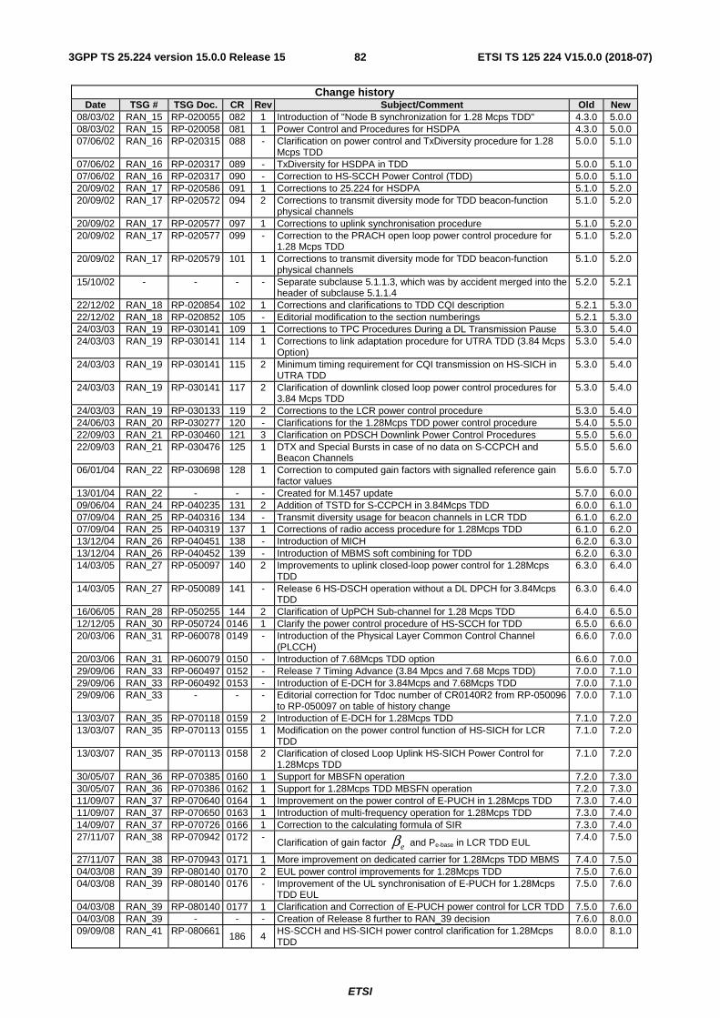
ETSI
ETSI TS 125 224 V15.0.0 (2018-07)823GPP TS 25.224 version 15.0.0 Release 15
Change history Date TSG # TSG Doc. CR Rev Subject/Comment Old New
08/03/02 RAN_15 RP-020055 082 1 Introduction of "Node B synchronization for 1.28 Mcps TDD" 4.3.0 5.0.0 08/03/02 RAN_15 RP-020058 081 1 Power Control and Procedures for HSDPA 4.3.0 5.0.0 07/06/02 RAN_16 RP-020315 088 - Clarification on power control and TxDiversity procedure for 1.28
Mcps TDD 5.0.0 5.1.0
07/06/02 RAN_16 RP-020317 089 - TxDiversity for HSDPA in TDD 5.0.0 5.1.0 07/06/02 RAN_16 RP-020317 090 - Correction to HS-SCCH Power Control (TDD) 5.0.0 5.1.0 20/09/02 RAN_17 RP-020586 091 1 Corrections to 25.224 for HSDPA 5.1.0 5.2.0 20/09/02 RAN_17 RP-020572 094 2 Corrections to transmit diversity mode for TDD beacon-function
physical channels 5.1.0 5.2.0
20/09/02 RAN_17 RP-020577 097 1 Corrections to uplink synchronisation procedure 5.1.0 5.2.0 20/09/02 RAN_17 RP-020577 099 - Correction to the PRACH open loop power control procedure for
1.28 Mcps TDD 5.1.0 5.2.0
20/09/02 RAN_17 RP-020579 101 1 Corrections to transmit diversity mode for TDD beacon-function physical channels
5.1.0 5.2.0
15/10/02 - - - - Separate subclause 5.1.1.3, which was by accident merged into the header of subclause 5.1.1.4
5.2.0 5.2.1
22/12/02 RAN_18 RP-020854 102 1 Corrections and clarifications to TDD CQI description 5.2.1 5.3.0 22/12/02 RAN_18 RP-020852 105 - Editorial modification to the section numberings 5.2.1 5.3.0 24/03/03 RAN_19 RP-030141 109 1 Corrections to TPC Procedures During a DL Transmission Pause 5.3.0 5.4.0 24/03/03 RAN_19 RP-030141 114 1 Corrections to link adaptation procedure for UTRA TDD (3.84 Mcps
Option) 5.3.0 5.4.0
24/03/03 RAN_19 RP-030141 115 2 Minimum timing requirement for CQI transmission on HS-SICH in UTRA TDD
5.3.0 5.4.0
24/03/03 RAN_19 RP-030141 117 2 Clarification of downlink closed loop power control procedures for 3.84 Mcps TDD
5.3.0 5.4.0
24/03/03 RAN_19 RP-030133 119 2 Corrections to the LCR power control procedure 5.3.0 5.4.0 24/06/03 RAN_20 RP-030277 120 - Clarifications for the 1.28Mcps TDD power control procedure 5.4.0 5.5.0 22/09/03 RAN_21 RP-030460 121 3 Clarification on PDSCH Downlink Power Control Procedures 5.5.0 5.6.0 22/09/03 RAN_21 RP-030476 125 1 DTX and Special Bursts in case of no data on S-CCPCH and
Beacon Channels 5.5.0 5.6.0
06/01/04 RAN_22 RP-030698 128 1 Correction to computed gain factors with signalled reference gain factor values
5.6.0 5.7.0
13/01/04 RAN_22 - - - Created for M.1457 update 5.7.0 6.0.0 09/06/04 RAN_24 RP-040235 131 2 Addition of TSTD for S-CCPCH in 3.84Mcps TDD 6.0.0 6.1.0 07/09/04 RAN_25 RP-040316 134 - Transmit diversity usage for beacon channels in LCR TDD 6.1.0 6.2.0 07/09/04 RAN_25 RP-040319 137 1 Corrections of radio access procedure for 1.28Mcps TDD 6.1.0 6.2.0 13/12/04 RAN_26 RP-040451 138 - Introduction of MICH 6.2.0 6.3.0 13/12/04 RAN_26 RP-040452 139 - Introduction of MBMS soft combining for TDD 6.2.0 6.3.0 14/03/05 RAN_27 RP-050097 140 2 Improvements to uplink closed-loop power control for 1.28Mcps
TDD 6.3.0 6.4.0
14/03/05 RAN_27 RP-050089 141 - Release 6 HS-DSCH operation without a DL DPCH for 3.84Mcps TDD
6.3.0 6.4.0
16/06/05 RAN_28 RP-050255 144 2 Clarification of UpPCH Sub-channel for 1.28 Mcps TDD 6.4.0 6.5.0 12/12/05 RAN_30 RP-050724 0146 1 Clarify the power control procedure of HS-SCCH for TDD 6.5.0 6.6.0 20/03/06 RAN_31 RP-060078 0149 - Introduction of the Physical Layer Common Control Channel
(PLCCH) 6.6.0 7.0.0
20/03/06 RAN_31 RP-060079 0150 - Introduction of 7.68Mcps TDD option 6.6.0 7.0.0 29/09/06 RAN_33 RP-060497 0152 - Release 7 Timing Advance (3.84 Mpcs and 7.68 Mcps TDD) 7.0.0 7.1.0 29/09/06 RAN_33 RP-060492 0153 - Introduction of E-DCH for 3.84Mcps and 7.68Mcps TDD 7.0.0 7.1.0 29/09/06 RAN_33 - - - Editorial correction for Tdoc number of CR0140R2 from RP-050096
to RP-050097 on table of history change 7.0.0 7.1.0
13/03/07 RAN_35 RP-070118 0159 2 Introduction of E-DCH for 1.28Mcps TDD 7.1.0 7.2.0 13/03/07 RAN_35 RP-070113 0155 1 Modification on the power control function of HS-SICH for LCR
TDD 7.1.0 7.2.0
13/03/07 RAN_35 RP-070113 0158 2 Clarification of closed Loop Uplink HS-SICH Power Control for 1.28Mcps TDD
7.1.0 7.2.0
30/05/07 RAN_36 RP-070385 0160 1 Support for MBSFN operation 7.2.0 7.3.0 30/05/07 RAN_36 RP-070386 0162 1 Support for 1.28Mcps TDD MBSFN operation 7.2.0 7.3.0 11/09/07 RAN_37 RP-070640 0164 1 Improvement on the power control of E-PUCH in 1.28Mcps TDD 7.3.0 7.4.0 11/09/07 RAN_37 RP-070650 0163 1 Introduction of multi-frequency operation for 1.28Mcps TDD 7.3.0 7.4.0 14/09/07 RAN_37 RP-070726 0166 1 Correction to the calculating formula of SIR 7.3.0 7.4.0 27/11/07 RAN_38 RP-070942 0172 -
Clarification of gain factor and Pe-base in LCR TDD EUL
7.4.0 7.5.0
27/11/07 RAN_38 RP-070943 0171 1 More improvement on dedicated carrier for 1.28Mcps TDD MBMS 7.4.0 7.5.0 04/03/08 RAN_39 RP-080140 0170 2 EUL power control improvements for 1.28Mcps TDD 7.5.0 7.6.0 04/03/08 RAN_39 RP-080140 0176 - Improvement of the UL synchronisation of E-PUCH for 1.28Mcps
TDD EUL 7.5.0 7.6.0
04/03/08 RAN_39 RP-080140 0177 1 Clarification and Correction of E-PUCH power control for LCR TDD 7.5.0 7.6.0 04/03/08 RAN_39 - - - Creation of Release 8 further to RAN_39 decision 7.6.0 8.0.0 09/09/08 RAN_41 RP-080661 186 4 HS-SCCH and HS-SICH power control clarification for 1.28Mcps
TDD 8.0.0 8.1.0
eβ
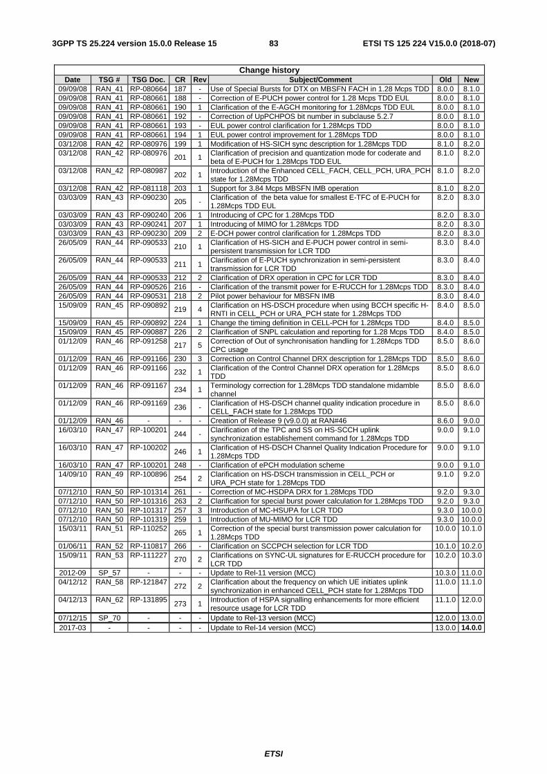
ETSI
ETSI TS 125 224 V15.0.0 (2018-07)833GPP TS 25.224 version 15.0.0 Release 15
Change history Date TSG # TSG Doc. CR Rev Subject/Comment Old New
09/09/08 RAN_41 RP-080664 187 - Use of Special Bursts for DTX on MBSFN FACH in 1.28 Mcps TDD 8.0.0 8.1.0 09/09/08 RAN_41 RP-080661 188 - Correction of E-PUCH power control for 1.28 Mcps TDD EUL 8.0.0 8.1.0 09/09/08 RAN_41 RP-080661 190 1 Clarification of the E-AGCH monitoring for 1.28Mcps TDD EUL 8.0.0 8.1.0 09/09/08 RAN_41 RP-080661 192 - Correction of UpPCHPOS bit number in subclause 5.2.7 8.0.0 8.1.0 09/09/08 RAN_41 RP-080661 193 - EUL power control clarification for 1.28Mcps TDD 8.0.0 8.1.0 09/09/08 RAN_41 RP-080661 194 1 EUL power control improvement for 1.28Mcps TDD 8.0.0 8.1.0 03/12/08 RAN_42 RP-080976 199 1 Modification of HS-SICH sync description for 1.28Mcps TDD 8.1.0 8.2.0 03/12/08 RAN_42 RP-080976
201 1 Clarification of precision and quantization mode for coderate and beta of E-PUCH for 1.28Mcps TDD EUL
8.1.0 8.2.0
03/12/08 RAN_42 RP-080987 202 1 Introduction of the Enhanced CELL_FACH, CELL_PCH, URA_PCH state for 1.28Mcps TDD
8.1.0 8.2.0
03/12/08 RAN_42 RP-081118 203 1 Support for 3.84 Mcps MBSFN IMB operation 8.1.0 8.2.0 03/03/09 RAN_43 RP-090230
205 - Clarification of the beta value for smallest E-TFC of E-PUCH for 1.28Mcps TDD EUL
8.2.0 8.3.0
03/03/09 RAN_43 RP-090240 206 1 Introducing of CPC for 1.28Mcps TDD 8.2.0 8.3.0 03/03/09 RAN_43 RP-090241 207 1 Introducing of MIMO for 1.28Mcps TDD 8.2.0 8.3.0 03/03/09 RAN_43 RP-090230 209 2 E-DCH power control clarification for 1.28Mcps TDD 8.2.0 8.3.0 26/05/09 RAN_44 RP-090533 210 1 Clarification of HS-SICH and E-PUCH power control in semi-
persistent transmission for LCR TDD 8.3.0 8.4.0
26/05/09 RAN_44 RP-090533 211 1
Clarification of E-PUCH synchronization in semi-persistent transmission for LCR TDD
8.3.0 8.4.0
26/05/09 RAN_44 RP-090533 212 2 Clarification of DRX operation in CPC for LCR TDD 8.3.0 8.4.0 26/05/09 RAN_44 RP-090526 216 - Clarification of the transmit power for E-RUCCH for 1.28Mcps TDD 8.3.0 8.4.0 26/05/09 RAN_44 RP-090531 218 2 Pilot power behaviour for MBSFN IMB 8.3.0 8.4.0 15/09/09 RAN_45 RP-090892 219 4 Clarification on HS-DSCH procedure when using BCCH specific H-
RNTI in CELL_PCH or URA_PCH state for 1.28Mcps TDD 8.4.0 8.5.0
15/09/09 RAN_45 RP-090892 224 1 Change the timing definition in CELL-PCH for 1.28Mcps TDD 8.4.0 8.5.0 15/09/09 RAN_45 RP-090887 226 2 Clarification of SNPL calculation and reporting for 1.28 Mcps TDD 8.4.0 8.5.0 01/12/09 RAN_46 RP-091258 217 5 Correction of Out of synchronisation handling for 1.28Mcps TDD
CPC usage 8.5.0 8.6.0
01/12/09 RAN_46 RP-091166 230 3 Correction on Control Channel DRX description for 1.28Mcps TDD 8.5.0 8.6.0 01/12/09 RAN_46 RP-091166 232 1 Clarification of the Control Channel DRX operation for 1.28Mcps
TDD 8.5.0 8.6.0
01/12/09 RAN_46 RP-091167 234 1 Terminology correction for 1.28Mcps TDD standalone midamble channel
8.5.0 8.6.0
01/12/09 RAN_46 RP-091169 236 - Clarification of HS-DSCH channel quality indication procedure in CELL_FACH state for 1.28Mcps TDD
8.5.0 8.6.0
01/12/09 RAN_46 - - - Creation of Release 9 (v9.0.0) at RAN#46 8.6.0 9.0.0 16/03/10 RAN_47 RP-100201 244 - Clarification of the TPC and SS on HS-SCCH uplink
synchronization establishement command for 1.28Mcps TDD 9.0.0 9.1.0
16/03/10 RAN_47 RP-100202 246 1 Clarification of HS-DSCH Channel Quality Indication Procedure for 1.28Mcps TDD
9.0.0 9.1.0
16/03/10 RAN_47 RP-100201 248 - Clarification of ePCH modulation scheme 9.0.0 9.1.0 14/09/10 RAN_49 RP-100896
254 2 Clarification on HS-DSCH transmission in CELL_PCH or URA_PCH state for 1.28Mcps TDD
9.1.0 9.2.0
07/12/10 RAN_50 RP-101314 261 - Correction of MC-HSDPA DRX for 1.28Mcps TDD 9.2.0 9.3.0 07/12/10 RAN_50 RP-101316 263 2 Clarification for special burst power calculation for 1.28Mcps TDD 9.2.0 9.3.0 07/12/10 RAN_50 RP-101317 257 3 Introduction of MC-HSUPA for LCR TDD 9.3.0 10.0.0 07/12/10 RAN_50 RP-101319 259 1 Introduction of MU-MIMO for LCR TDD 9.3.0 10.0.0 15/03/11 RAN_51 RP-110252
265 1 Correction of the special burst transmission power calculation for 1.28Mcps TDD
10.0.0 10.1.0
01/06/11 RAN_52 RP-110817 266 - Clarification on SCCPCH selection for LCR TDD 10.1.0 10.2.0 15/09/11 RAN_53 RP-111227 270 2 Clarifications on SYNC-UL signatures for E-RUCCH procedure for
LCR TDD 10.2.0 10.3.0
2012-09 SP_57 - - - Update to Rel-11 version (MCC) 10.3.0 11.0.0 04/12/12 RAN_58 RP-121847
272 2 Clarification about the frequency on which UE initiates uplink synchronization in enhanced CELL_PCH state for 1.28Mcps TDD
11.0.0 11.1.0
04/12/13 RAN_62 RP-131895 273 1 Introduction of HSPA signalling enhancements for more efficient resource usage for LCR TDD
11.1.0 12.0.0
07/12/15 SP_70 - - - Update to Rel-13 version (MCC) 12.0.0 13.0.0 2017-03 - - - - Update to Rel-14 version (MCC) 13.0.0 14.0.0
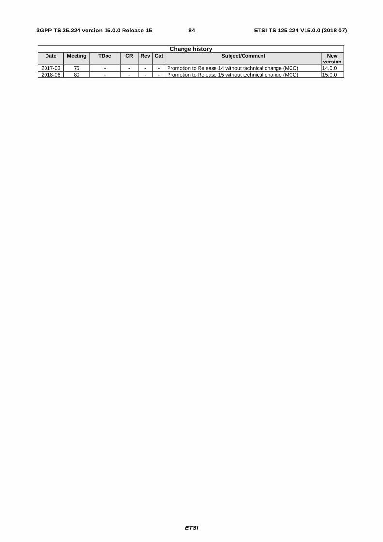
ETSI
ETSI TS 125 224 V15.0.0 (2018-07)843GPP TS 25.224 version 15.0.0 Release 15
Change history Date Meeting TDoc CR Rev Cat Subject/Comment New
version 2017-03 75 - - - - Promotion to Release 14 without technical change (MCC) 14.0.0 2018-06 80 - - - - Promotion to Release 15 without technical change (MCC) 15.0.0

ETSI
ETSI TS 125 224 V15.0.0 (2018-07)853GPP TS 25.224 version 15.0.0 Release 15
History
Document history
V15.0.0 July 2018 Publication