Embed Size (px)
Citation preview
ETSI TS 133 127 V15.0.0 (2018-12)
LTE; 5G;
Digital cellular telecommunications system (Phase 2+) (GSM); Universal Mobile Telecommunications System (UMTS);
Lawful Interception (LI) architecture and functions (3GPP TS 33.127 version 15.0.0 Release 15)
TECHNICAL SPECIFICATION
ETSI
ETSI TS 133 127 V15.0.0 (2018-12)13GPP TS 33.127 version 15.0.0 Release 15
Reference DTS/TSGS-0333127vf00
Keywords 5G,GSM,LTE,SECURITY,UMTS
ETSI
650 Route des Lucioles F-06921 Sophia Antipolis Cedex - FRANCE
Tel.: +33 4 92 94 42 00 Fax: +33 4 93 65 47 16
Siret N° 348 623 562 00017 - NAF 742 C
Association à but non lucratif enregistrée à la Sous-Préfecture de Grasse (06) N° 7803/88
Important notice
The present document can be downloaded from: http://www.etsi.org/standards-search
The present document may be made available in electronic versions and/or in print. The content of any electronic and/or print versions of the present document shall not be modified without the prior written authorization of ETSI. In case of any
existing or perceived difference in contents between such versions and/or in print, the only prevailing document is the print of the Portable Document Format (PDF) version kept on a specific network drive within ETSI Secretariat.
Users of the present document should be aware that the document may be subject to revision or change of status. Information on the current status of this and other ETSI documents is available at
https://portal.etsi.org/TB/ETSIDeliverableStatus.aspx
If you find errors in the present document, please send your comment to one of the following services: https://portal.etsi.org/People/CommiteeSupportStaff.aspx
Copyright Notification
No part may be reproduced or utilized in any form or by any means, electronic or mechanical, including photocopying and microfilm except as authorized by written permission of ETSI.
The content of the PDF version shall not be modified without the written authorization of ETSI. The copyright and the foregoing restriction extend to reproduction in all media.
© ETSI 2018.
All rights reserved.
DECTTM, PLUGTESTSTM, UMTSTM and the ETSI logo are trademarks of ETSI registered for the benefit of its Members. 3GPPTM and LTETM are trademarks of ETSI registered for the benefit of its Members and
of the 3GPP Organizational Partners. oneM2M™ logo is a trademark of ETSI registered for the benefit of its Members and
of the oneM2M Partners GSM® and the GSM logo are trademarks registered and owned by the GSM Association.
ETSI
ETSI TS 133 127 V15.0.0 (2018-12)23GPP TS 33.127 version 15.0.0 Release 15
Intellectual Property Rights Essential patents
IPRs essential or potentially essential to normative deliverables may have been declared to ETSI. The information pertaining to these essential IPRs, if any, is publicly available for ETSI members and non-members, and can be found in ETSI SR 000 314: "Intellectual Property Rights (IPRs); Essential, or potentially Essential, IPRs notified to ETSI in respect of ETSI standards", which is available from the ETSI Secretariat. Latest updates are available on the ETSI Web server (https://ipr.etsi.org/).
Pursuant to the ETSI IPR Policy, no investigation, including IPR searches, has been carried out by ETSI. No guarantee can be given as to the existence of other IPRs not referenced in ETSI SR 000 314 (or the updates on the ETSI Web server) which are, or may be, or may become, essential to the present document.
Trademarks
The present document may include trademarks and/or tradenames which are asserted and/or registered by their owners. ETSI claims no ownership of these except for any which are indicated as being the property of ETSI, and conveys no right to use or reproduce any trademark and/or tradename. Mention of those trademarks in the present document does not constitute an endorsement by ETSI of products, services or organizations associated with those trademarks.
Foreword This Technical Specification (TS) has been produced by ETSI 3rd Generation Partnership Project (3GPP).
The present document may refer to technical specifications or reports using their 3GPP identities, UMTS identities or GSM identities. These should be interpreted as being references to the corresponding ETSI deliverables.
The cross reference between GSM, UMTS, 3GPP and ETSI identities can be found under http://webapp.etsi.org/key/queryform.asp.
Modal verbs terminology In the present document "shall", "shall not", "should", "should not", "may", "need not", "will", "will not", "can" and "cannot" are to be interpreted as described in clause 3.2 of the ETSI Drafting Rules (Verbal forms for the expression of provisions).
"must" and "must not" are NOT allowed in ETSI deliverables except when used in direct citation.
ETSI
ETSI TS 133 127 V15.0.0 (2018-12)33GPP TS 33.127 version 15.0.0 Release 15
Contents Intellectual Property Rights ................................................................................................................................ 2
Foreword ............................................................................................................................................................. 2
Modal verbs terminology .................................................................................................................................... 2
Foreword ............................................................................................................................................................. 6
Introduction ........................................................................................................................................................ 6
1 Scope ........................................................................................................................................................ 7
2 References ................................................................................................................................................ 7
3 Definitions, symbols and abbreviations ................................................................................................... 7
3.1 Definitions .......................................................................................................................................................... 7
3.2 Symbols .............................................................................................................................................................. 8
3.3 Abbreviations ..................................................................................................................................................... 8
4 Requirements realisation .......................................................................................................................... 9
5 Functional architecture ............................................................................................................................. 9
5.1 General ............................................................................................................................................................... 9
5.2 High-level generic LI architecture .................................................................................................................... 10
5.3 Functional entities ............................................................................................................................................ 11
5.3.1 Law Enforcement Agency (LEA) ............................................................................................................... 11
5.3.2 Point of Interception (POI) ......................................................................................................................... 11
5.3.2.1 General .................................................................................................................................................. 11
5.3.2.2 Directly provisioned and triggered POIs ............................................................................................... 11
5.3.2.3 IRI-POIs and CC-POIs .......................................................................................................................... 11
5.3.2.4 Failure handling .................................................................................................................................... 11
5.3.3 Triggering Function .................................................................................................................................... 11
5.3.4 Mediation and Delivery Function (MDF) ................................................................................................... 12
5.3.5 Administrative Function (ADMF) .............................................................................................................. 12
5.3.5.1 General .................................................................................................................................................. 12
5.3.5.2 LICF ...................................................................................................................................................... 13
5.3.5.3 LIPF ...................................................................................................................................................... 13
5.3.6 System Information Retrieval Function (SIRF) .......................................................................................... 13
5.3.7 LEMF – Law Enforcement Monitoring Facility ......................................................................................... 13
5.4 LI interfaces ...................................................................................................................................................... 14
5.4.1 General ........................................................................................................................................................ 14
5.4.2 Interface LI_SI ............................................................................................................................................ 14
5.4.3 Interface LI_HI1 ......................................................................................................................................... 14
5.4.4 Interface LI_X1 .......................................................................................................................................... 15
5.4.4.1 General .................................................................................................................................................. 15
5.4.4.2 LIPF and POI ........................................................................................................................................ 15
5.4.4.3 LIPF and TF .......................................................................................................................................... 15
5.4.4.4 LIPF and MDF2/MDF3 ........................................................................................................................ 16
5.4.5 Interface LI_X2 .......................................................................................................................................... 16
5.4.6 Interface LI_X3 .......................................................................................................................................... 16
5.4.7 Interface LI_T ............................................................................................................................................. 16
5.4.7.1 General .................................................................................................................................................. 16
5.4.7.2 Interface LI_T2 ..................................................................................................................................... 17
5.4.7.3 Interface LI_T3 ..................................................................................................................................... 17
5.4.8 Interface LI_HI2 ......................................................................................................................................... 17
5.4.9 Interface LI_HI3 ......................................................................................................................................... 17
5.4.10 Interface LI_HI4 ......................................................................................................................................... 17
5.4.10.1 General .................................................................................................................................................. 17
5.4.10.2 LI operation notification ....................................................................................................................... 17
5.4.10.3 Contents of the notification ................................................................................................................... 18
5.4.11 Interface LI_ADMF .................................................................................................................................... 18
5.4.12 Interface LI_MDF ....................................................................................................................................... 18
ETSI
ETSI TS 133 127 V15.0.0 (2018-12)43GPP TS 33.127 version 15.0.0 Release 15
5.5 LI service discovery ......................................................................................................................................... 18
5.6 LI in a virtualised environment ........................................................................................................................ 18
5.6.1 General ........................................................................................................................................................ 18
5.6.2 Virtualised deployment architecture ........................................................................................................... 18
6 Network layer based interception ........................................................................................................... 20
6.1 General ............................................................................................................................................................. 20
6.2 5G ..................................................................................................................................................................... 20
6.2.1 General ........................................................................................................................................................ 20
6.2.2 LI at AMF ................................................................................................................................................... 21
6.2.2.1 Architecture ........................................................................................................................................... 21
6.2.2.2 Target identities ..................................................................................................................................... 22
6.2.2.3 Identity privacy ..................................................................................................................................... 23
6.2.2.4 IRI events .............................................................................................................................................. 23
6.2.2.5 Common IRI parameters ....................................................................................................................... 23
6.2.2.6 Specific IRI parameters ......................................................................................................................... 23
6.2.2.7 Network topologies ............................................................................................................................... 24
6.2.3 LI for SMF/UPF ......................................................................................................................................... 24
6.2.3.1 Architecture ........................................................................................................................................... 24
6.2.3.2 Target identities ..................................................................................................................................... 26
6.2.3.3 IRI events .............................................................................................................................................. 27
6.2.3.4 Common IRI parameters ....................................................................................................................... 27
6.2.3.5 Specific IRI parameters ......................................................................................................................... 27
6.2.3.6 Network topologies ............................................................................................................................... 27
6.2.4 LI at UDM for 5G ....................................................................................................................................... 28
6.2.5 LI at SMSF ................................................................................................................................................. 28
6.2.5.1 Architecture ........................................................................................................................................... 28
6.2.5.2 Target identities ..................................................................................................................................... 29
6.2.5.3 IRI events .............................................................................................................................................. 30
6.2.5.4 Common IRI parameters ....................................................................................................................... 30
6.2.5.5 Specific IRI parameters ......................................................................................................................... 30
6.2.5.6 Network topologies ............................................................................................................................... 30
6.2.6 LI support at NRF ....................................................................................................................................... 30
6.2.6.1 Architecture ........................................................................................................................................... 30
6.2.6.2 LI_SI notifications ................................................................................................................................ 31
6.2.6.3 LI_SI parameters ................................................................................................................................... 31
6.2.7 External data storage ................................................................................................................................... 31
6.3 4G ..................................................................................................................................................................... 32
6.4 3G ..................................................................................................................................................................... 32
7 Service layer based interception ............................................................................................................. 32
7.1 General ............................................................................................................................................................. 32
7.2 Central subscriber management ....................................................................................................................... 32
7.2.1 General ........................................................................................................................................................ 32
7.2.2 LI at UDM .................................................................................................................................................. 32
7.2.2.1 Architecture ........................................................................................................................................... 32
7.2.2.2 Target identities ..................................................................................................................................... 33
7.2.2.3 Identity privacy ..................................................................................................................................... 34
7.2.2.4 IRI events .............................................................................................................................................. 34
7.2.2.5 Common IRI parameters ....................................................................................................................... 34
7.2.2.6 Specific IRI parameters ......................................................................................................................... 34
7.2.2.7 Network topologies ............................................................................................................................... 34
7.2.3 LI at HSS .................................................................................................................................................... 34
7.3 Location ............................................................................................................................................................ 35
7.3.1 General ........................................................................................................................................................ 35
7.3.2 Service usage location reporting ................................................................................................................. 35
7.3.2.1 General .................................................................................................................................................. 35
7.3.2.2 Embedded location reporting ................................................................................................................ 35
7.3.2.3 Separated location reporting.................................................................................................................. 35
7.3.3 Lawful Access Location Services (LALS) ................................................................................................. 36
7.3.3.1 General .................................................................................................................................................. 36
7.3.3.2 Target positioning ................................................................................................................................. 36
ETSI
ETSI TS 133 127 V15.0.0 (2018-12)53GPP TS 33.127 version 15.0.0 Release 15
7.3.3.2.1 General ............................................................................................................................................ 36
7.3.3.2.2 Immediate location provision .......................................................................................................... 37
7.3.3.2.3 Periodic location provision .............................................................................................................. 37
7.3.3.3 Triggered location ................................................................................................................................. 37
7.3.3.4 LI_X2 interface for target positioning and triggered location ............................................................... 38
7.3.4 Cell database information reporting ............................................................................................................ 39
8 LI security considerations ...................................................................................................................... 40
8.1 Introduction ...................................................................................................................................................... 40
8.2 Architectural alternatives ................................................................................................................................. 40
8.2.1 Full target list at every POI node ................................................................................................................ 40
8.2.2 Full target list only in LICF ........................................................................................................................ 40
8.2.3 Provisioning for registered users ................................................................................................................ 40
8.3 LI key management at ADMF .......................................................................................................................... 40
8.3.1 General ........................................................................................................................................................ 40
8.3.2 Key management ........................................................................................................................................ 41
8.4 Virtualised LI security ...................................................................................................................................... 41
8.4.1 General ........................................................................................................................................................ 41
8.5 Points of Interception ....................................................................................................................................... 41
Annex A (informative): 5G LI network topology views ...................................................................... 43
A.1 Non-roaming scenario ............................................................................................................................ 43
A.1.1 General ............................................................................................................................................................. 43
A.1.2 Service-based representation with point-to-point LI system ............................................................................ 43
A.2 Interworking with EPC/E-UTRAN ........................................................................................................ 44
A.2.1 General ............................................................................................................................................................. 44
A.2.2 Topology view for a non-roaming scenario ..................................................................................................... 45
A.3 Multiple DN connections in a PDU session ........................................................................................... 47
A.3.1 General ............................................................................................................................................................. 47
A.3.2 Topology view for a non-roaming scenario ..................................................................................................... 47
A.4 Non-3GPP access in a non-roaming scenario ........................................................................................ 49
A.4.1 General ............................................................................................................................................................. 49
A.4.2 Topology view .................................................................................................................................................. 49
Annex Z (informative): Change history ............................................................................................... 51
History .............................................................................................................................................................. 52
ETSI
ETSI TS 133 127 V15.0.0 (2018-12)63GPP TS 33.127 version 15.0.0 Release 15
Foreword This Technical Specification has been produced by the 3rd Generation Partnership Project (3GPP).
The contents of the present document are subject to continuing work within the TSG and may change following formal TSG approval. Should the TSG modify the contents of the present document, it will be re-released by the TSG with an identifying change of release date and an increase in version number as follows:
Version x.y.z
where:
x the first digit:
1 presented to TSG for information;
2 presented to TSG for approval;
3 or greater indicates TSG approved document under change control.
y the second digit is incremented for all changes of substance, i.e. technical enhancements, corrections, updates, etc.
z the third digit is incremented when editorial only changes have been incorporated in the document.
Introduction The present document has been produced by the 3GPP TSG SA to standardise Lawful Interception of telecommunications. The present document specifies the architecture and functions required to support Lawful Interception in 3GPP networks. Lawful Interception shall always be done in accordance with the applicable national or regional laws and technical regulations. Such national laws and regulations define the extent to which functional capabilities in the present document are applicable in specific jurisdictions.
ETSI
ETSI TS 133 127 V15.0.0 (2018-12)73GPP TS 33.127 version 15.0.0 Release 15
1 Scope The present document specifies both the architectural and functional system requirements for Lawful Interception (LI) in 3GPP networks. The present document provides an LI architecture supporting both network layer based and service layer based Interception.
National regulations determine the specific set of LI functional capabilities that are applicable to a specific 3GPP operator deployment.
2 References The following documents contain provisions which, through reference in this text, constitute provisions of the present document.
- References are either specific (identified by date of publication, edition number, version number, etc.) or non-specific.
- For a specific reference, subsequent revisions do not apply.
- For a non-specific reference, the latest version applies. In the case of a reference to a 3GPP document (including a GSM document), a non-specific reference implicitly refers to the latest version of that document in the same Release as the present document.
[1] 3GPP TR 21.905: "Vocabulary for 3GPP Specifications".
[2] 3GPP TS 23.501: "System Architecture for the 5G System".
[3] 3GPP TS 33.126: "Lawful interception requirements".
[4] 3GPP TS 23.502: "Procedures for the 5G System; Stage 2".
[5] 3GPP TS 23.271: "Functional stage 2 description of Location Services (LCS)".
[6] OMA MLP: "Mobile Location Protocol V3.3".
NOTE: Available at http://www.openmobilealliance.org.
[7] ETSI TS 103 120: "Lawful Interception (LI); Interface for warrant information".
[8] ETSI TS 103 221-1: "Lawful Interception (LI); Part 1: Internal Network Interface X1 for Lawful Interception".
[9] 3GPP TS 33.501: "Security Architecture and Procedures for the 5G System".
[10] ETSI GR NFV-SEC 011: "Network Functions Virtualisation (NFV); Security; Report on NFV LI Architecture".
[11] 3GPP TS 33.107: "3G Security; Lawful interception architecture and functions".
[12] 3GPP TS 23.214: "Architecture enhancements for control and user plane separation of EPC nodes; Stage 2".
3 Definitions, symbols and abbreviations
3.1 Definitions For the purposes of the present document, the terms and definitions given in 3GPP TR 21.905 [1] and the following apply. A term defined in the present document takes precedence over the definition of the same term, if any, in 3GPP TR 21.905 [1].
Content of Communication (CC): The content of communication as forwarded from the Mediation and Delivery Function 3 (over the LI_HI3 interface) to the Law Enforcement Monitoring Facility.
ETSI
ETSI TS 133 127 V15.0.0 (2018-12)83GPP TS 33.127 version 15.0.0 Release 15
CUPS: As defined in 3GPP TS 23.214 [12], represents PLMN with architecture enhancements for control and user plane separation of EPC nodes.
Intercept Related Information (IRI): The intercept related information as forwarded from the Mediation and Delivery Function 2 (over the LI_HI2 interface) to the Law Enforcement Monitoring Facility.
IRI event: The network procedure or event that created an xIRI in the Point Of Interception.
LI component: The function and equipment involved in handling the Lawful Interception functionality in the CSP's network.
LI system: The collection of all LI components involved in handling the Lawful Interception functionality in the CSP's network.
Provisioning: The action taken by the CSP to provide its Lawful Interception functions information that identifies the target and the specific communication services of interest to the LEA, sourced from the LEA provided warrant.
Triggering: The action taken by a dedicated function (Triggering Function) to provide another dedicated function (Triggered POI), that Provisioning could not directly be applied to, with information that identifies the specific target communication to be intercepted.
Warrant: The formal mechanism to require Lawful Interception from a LEA served to the CSP on a single target identifier. Depending on jurisdiction also known as: intercept request, intercept order, lawful order, court order, lawful order or judicial order (in association with supporting legislation).
xCC: The content of communication as forwarded from the Point Of Interception (over the LI_X3) interface to the Mediation and Delivery Function 3.
xIRI: The intercept related information as forwarded from the Point Of Interception (over the LI_X2) interface to the Mediation and Delivery Function 2.
3.2 Symbols
3.3 Abbreviations For the purposes of the present document, the abbreviations given in 3GPP TR 21.905 [1] and the following apply. An abbreviation defined in the present document takes precedence over the definition of the same abbreviation, if any, in 3GPP TR 21.905 [1].
5GC 5G Core Network 5GS 5G System ADMF LI Administration Function AMF Access Management Function AUSF Authentication Server Function CC Content of Communication CSI Cell Supplemental Information CSP Communication Service Provider CUPS Control and User Plane Separation DN Data Network GPSI Generic Public Subscription Identifier IP Interception Product IRI Intercept Related Information LALS Lawful Access Location Services LEA Law Enforcement Agency LEMF Law Enforcement Monitoring Facility LI Lawful Interception LICA Lawful Interception Certificate Authority LICF Lawful Interception Control Function LI_HI1 Lawful Interception Handover Interface 1 LI_HI2 Lawful Interception Handover Interface 2 LI_HI3 Lawful Interception Handover Interface 3 LI_HI4 Lawful Interception Handover Interface 4 LIPF Lawful Interception Provisioning Function
ETSI
ETSI TS 133 127 V15.0.0 (2018-12)93GPP TS 33.127 version 15.0.0 Release 15
LIR Location Immediate Request LI_SI Lawful Interception System Information Interface LI_X0 Lawful Interception Internal Interface 0 LI_X1 Lawful Interception Internal Interface 1 LI_X2 Lawful Interception Internal Interface 2 LI_X3 Lawful Interception Internal Interface 3 LMF Location Management Function LTF Location Triggering Function MDF Mediation and Delivery Function MDF2 Mediation and Delivery Function 2 MDF3 Mediation and Delivery Function 3 N3IWF Non 3GPP Inter Working Function NPLI Network Provided Location Information NR New Radio NRF Network Repository Function NSSF Network Slice Selection Function PCF Policy Control Function PEI Permanent Equipment Identifier POI Point Of Interception SIRF System Information Retrieval Function SMF Session Management Function SMSF SMS-Function SUCI Subscriber Concealed Identifier SUPI Subscriber Permanent Identifier TF Triggering Function UDM Unified Data Management UDR Unified Data Repository UDSF Unstructured Data Storage Function UPF User Plane Function xCC LI_X3 Communications Content xIRI LI_X2 Intercept Related Information
4 Requirements realisation The LI architecture set out in the present document is designed to allow CSP deployments to meet the set of LI requirements described in TS 33.126 [3] that are determined to be applicable by the relevant national regulation for that deployment. For more details on the relationship between LI requirements and national legislation, see TS 33.126 [3] clause 4.
A CSP may deploy different network technologies or services considered in the present document. A CSP should consider each of these network technologies or services separately with respect to the present document, bearing in mind that a different subset of LI requirements may apply according to relevant national legislation, and that a warrant may require the CSP to intercept multiple network technologies or services.
5 Functional architecture
5.1 General The following clauses describe the high-level functional architecture for LI for 3GPP-defined services and network technologies. It describes the architectural elements necessary for LI, their roles and responsibilities, and the interfaces and interactions between them.
Clauses 6 and 7 of the present document describe how the LI for various 3GPP-defined network technologies and services are realised within the generic LI architecture, including associations of LI architectural elements with the network functions involved.
Not all LI architectural elements and interfaces are used in all network technologies and services.
ETSI
ETSI TS 133 127 V15.0.0 (2018-12)103GPP TS 33.127 version 15.0.0 Release 15
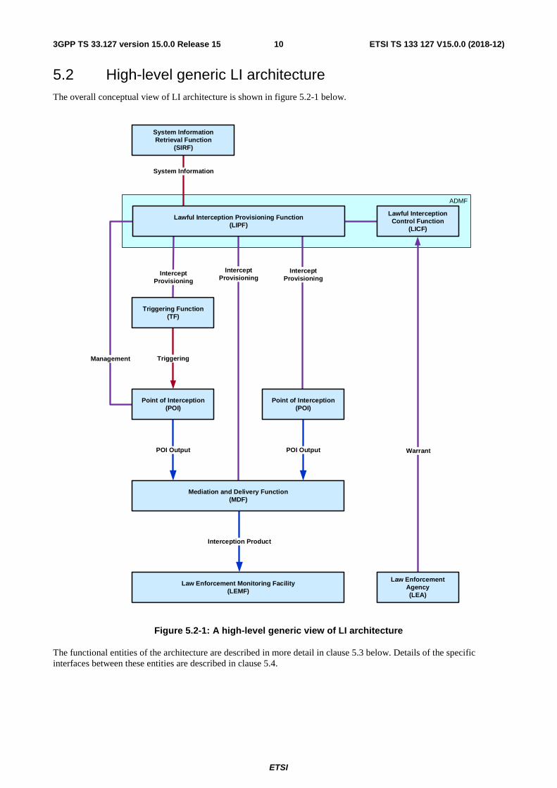
5.2 High-level generic LI architecture The overall conceptual view of LI architecture is shown in figure 5.2-1 below.
Triggering
POI Output POI Output
Interception Product
System Information
InterceptProvisioning
Warrant
ADMF
InterceptProvisioning
Management
InterceptProvisioning
Mediation and Delivery Function(MDF)
Law Enforcement Monitoring Facility(LEMF)
Lawful Interception Provisioning Function(LIPF)
Point of Interception (POI)
System InformationRetrieval Function
(SIRF)
Lawful Interception Control Function
(LICF)
Law Enforcement Agency(LEA)
Triggering Function(TF)
Point of Interception(POI)
Figure 5.2-1: A high-level generic view of LI architecture
The functional entities of the architecture are described in more detail in clause 5.3 below. Details of the specific interfaces between these entities are described in clause 5.4.
ETSI
ETSI TS 133 127 V15.0.0 (2018-12)113GPP TS 33.127 version 15.0.0 Release 15
5.3 Functional entities
5.3.1 Law Enforcement Agency (LEA)
In general the LEA is responsible for submitting the warrant to the CSPs, although in some countries the warrant may be provided by a different legal entity (e.g. judiciary).
5.3.2 Point of Interception (POI)
5.3.2.1 General
The Point of Interception (POI) detects the target communication, derives the intercept related information or communications content from the target communications and delivers the POI Output as xIRI to the MDF2 or as xCC to the MDF3. The output of a POI is determined by the type of the NF associated with the POI. A POI may be embedded within a Network Function (NF) or separate from a NF with which it is associated.
Multiple POIs may have to be involved in executing a warrant.
5.3.2.2 Directly provisioned and triggered POIs
POIs are divided into two categories:
- Directly provisioned POIs are provisioned by the LIPF.
- Triggered POIs are triggered by a Triggering Function (TF) (see clause 5.3.3).
The directly provisioned POIs detect the target's communications that need to be intercepted, and then derive the intercept related information or communication contents from that target communications depending on the POI type (see clause 5.3.2.3). The triggered POIs detects the target communications based on the trigger received from an associated Triggering Function and then derives the intercept related information or communication contents of target communications depending on the POI type (see clause 5.3.2.3).
5.3.2.3 IRI-POIs and CC-POIs
POIs are divided into two types for each category based on the type of data they send to the MDF (see clause 5.3.4):
- IRI-POI delivers xIRI to the MDF2.
- CC-POI delivers xCC to the MDF3.
Both IRI-POIs and CC-POIs are either directly provisioned or triggered (see clause 5.3.2.2).
5.3.2.4 Failure handling
In case a network procedure involving the target UE and requiring the generation of an xIRI fails, the IRI-POI shall be able to report the failure reason available from the involved network protocol.
5.3.3 Triggering Function
The Triggering Function is provisioned by the LIPF and is responsible for triggering triggered POIs in response to network and service events matching the criteria provisioned by the LIPF. The Triggering Function detects the target communications and sends a trigger to the associated triggered POI.
As a part of this triggering, the Triggering Function shall send all necessary interception rules (i.e. rules that allow the POIs to detect the target communications), forwarding rules (i.e. MDF2, MDF3 address), target identity, and the correlation information.
A Triggering Function may interact with other POIs to obtain correlation information. Details of this interface are not specified by the present document.
The Triggering Function that triggers CC-POI is referred to as a CC-TF and the Triggering Function that triggers an IRI-POI is referred to as IRI-TF.
ETSI
ETSI TS 133 127 V15.0.0 (2018-12)123GPP TS 33.127 version 15.0.0 Release 15
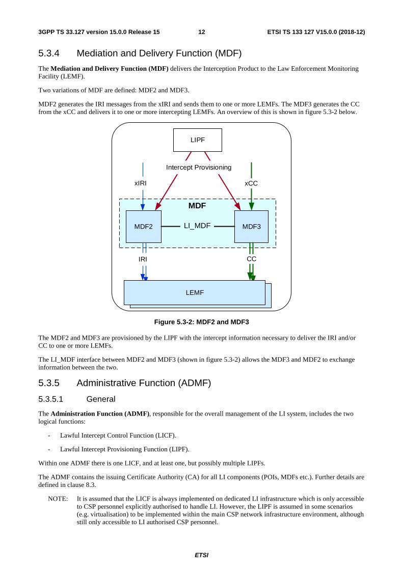
5.3.4 Mediation and Delivery Function (MDF)
The Mediation and Delivery Function (MDF) delivers the Interception Product to the Law Enforcement Monitoring Facility (LEMF).
Two variations of MDF are defined: MDF2 and MDF3.
MDF2 generates the IRI messages from the xIRI and sends them to one or more LEMFs. The MDF3 generates the CC from the xCC and delivers it to one or more intercepting LEMFs. An overview of this is shown in figure 5.3-2 below.
LEMF
MDF2
xIRI
MDF3
LEMF
IRI CC
xCC
LIPF
Intercept Provisioning
MDF
LI_MDF
Figure 5.3-2: MDF2 and MDF3
The MDF2 and MDF3 are provisioned by the LIPF with the intercept information necessary to deliver the IRI and/or CC to one or more LEMFs.
The LI_MDF interface between MDF2 and MDF3 (shown in figure 5.3-2) allows the MDF3 and MDF2 to exchange information between the two.
5.3.5 Administrative Function (ADMF)
5.3.5.1 General
The Administration Function (ADMF), responsible for the overall management of the LI system, includes the two logical functions:
- Lawful Intercept Control Function (LICF).
- Lawful Intercept Provisioning Function (LIPF).
Within one ADMF there is one LICF, and at least one, but possibly multiple LIPFs.
The ADMF contains the issuing Certificate Authority (CA) for all LI components (POIs, MDFs etc.). Further details are defined in clause 8.3.
NOTE: It is assumed that the LICF is always implemented on dedicated LI infrastructure which is only accessible to CSP personnel explicitly authorised to handle LI. However, the LIPF is assumed in some scenarios (e.g. virtualisation) to be implemented within the main CSP network infrastructure environment, although still only accessible to LI authorised CSP personnel.
ETSI
ETSI TS 133 127 V15.0.0 (2018-12)133GPP TS 33.127 version 15.0.0 Release 15
5.3.5.2 LICF
The LICF controls the management of the end-to-end life cycle of a warrant. The LICF contains the master record of all sensitive information and LI configuration data. The LICF is ultimately responsible for all decisions within the overall LI system. The LICF, via the LIPF acting as its proxy is responsible for auditing other LI components (POIs, MDFs etc.). The LICF is responsible for communication with administrative LEA systems (LI_HI1).
The LICF provides the intercept information derived from the warrant for provisioning at the POI, TF, MDF2 and MDF3.With the exception of the communication with the LEA, all other communication between the LICF and any other entities shall be proxied by the LIPF.
The LICF also maintains and authorises the master list of POIs, TFs and MDFs. In dynamic networks the LIPF is responsible for providing the LICF with any necessary updates to the POI/TF and MDF list.
5.3.5.3 LIPF
The LIPF provisions all the applicable POIs, TFs and MDFs.
The role of the LIPF varies depending on implementation of network functions and of the ADMF itself (e.g. virtual or non-virtual).
In its simplest form, the LIPF is the secure proxy used by the LICF to communicate with POIs, TFs, MDFs or other infrastructure required to operate LI within the CSP network. In this scenario the LIPF does not store target information and simply routes LI_X1 messages from and to the LICF.
In scenarios where the ADMF is required to take an active role in POI triggering, the LIPF is responsible for receiving triggering information (e.g. from an IRI-TF) and forwarding the trigger to the appropriate POI.
For directly provisioned POIs, TFs and MDFs, the LIPF will forward all LI administration instructions from the LICF to the intended destination POI, TF or MDF.
In SBA as defined in TS 23.501 [2] or virtualised deployments, the LIPF is responsible for identifying changes to NFs, POIs, and TFs and MDFs through interaction with the SIRF or underlying virtualisation infrastructure. The LIPF shall notify the LICF of changes affecting the number of active NFs/POIs and TFs or other information which the LICF requires to maintain the master POI/TF and MDF list.
While the LIPF is assumed to be stateful with respect to dynamic interceptions it is managing, it shall not hold the full static target or other historic LI data. If the LIPF is deployed in a virtualised environment, the LIPF shall not store LI information in persistent storage and shall rely on the LICF to manage re-synchronisation in the case of LIPF restart.
5.3.6 System Information Retrieval Function (SIRF)
The System Information Retrieval Function (SIRF) is responsible for providing the LIPF with the system related information for NFs that are known by the SIRF (e.g. service topology). The information provided shall allow the LIPF/LICF to perform the necessary operations to establish and maintain interception of the target service (e.g. provisioning POIs, TFs and MDFs over LI_X1). LIPF/LICF knowledge of POI, TF and MDF existence is provided directly by interactions between the LIPF/LICF and the underlying CSP management systems that instantiate NFs (as defined in clause 5.5). The NRF/SIRF are not involved in this step of NF/POI or MDF instantiation.
While the LIPF is responsible for interactions with the SIRF, the LIPF will forward applicable information to the LICF. Details of LIPF vs LICF responsibilities in managing and maintaining interception are defined in clause 5.3.2.
NOTE: The SIRF is not responsible for notifying the LIPF that a POI, TF or MDF has been instantiated. The LIPF is notified of these events directly by the relevant CSP management system, as described in clause 5.5, prior to any interaction with the SIRF. When the SIRF subsequently notifies the LIPF that, for example an NF associated with a POI has now been registered with the SIRF, the LIPF then knows the NF and POI is ready for live user traffic service.
5.3.7 LEMF – Law Enforcement Monitoring Facility
The Law Enforcement Monitoring Facility (LEMF) receives the Interception Product. The LEMF is out of scope of the present document.
ETSI
ETSI TS 133 127 V15.0.0 (2018-12)143GPP TS 33.127 version 15.0.0 Release 15
5.4 LI interfaces
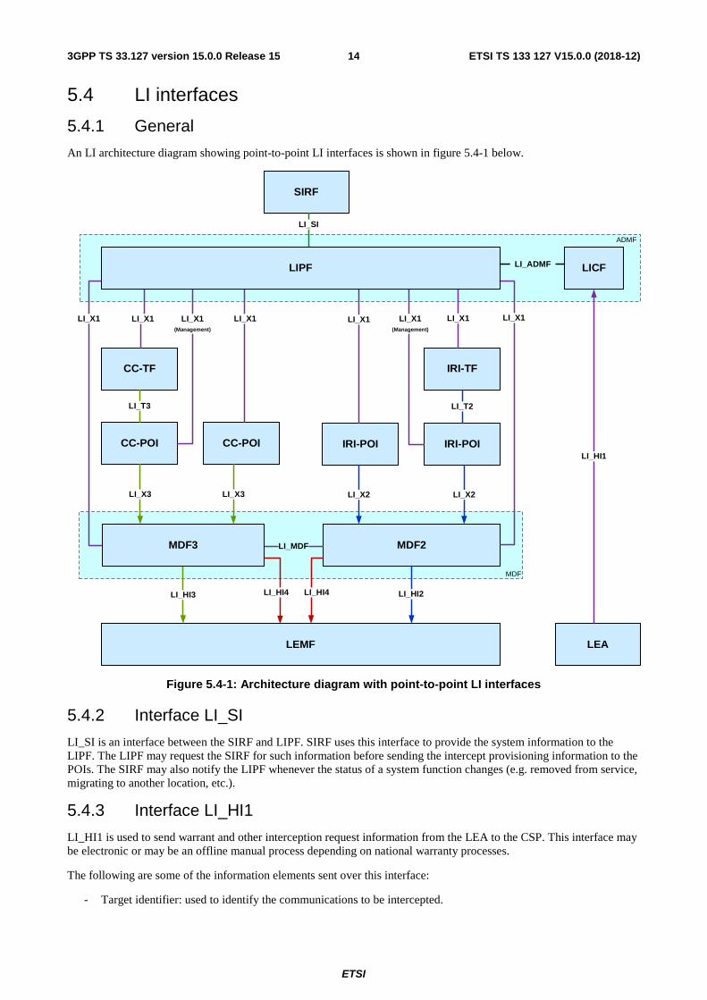
5.4.1 General
An LI architecture diagram showing point-to-point LI interfaces is shown in figure 5.4-1 below.
LICF
MDF2
IRI-POI
LEMF LEA
SIRF
CC-POI CC-POI IRI-POI
CC-TF IRI-TF
LI_T3
LI_X3
LI_X1 LI_X1 (Management)
LI_X3
LI_HI3
LI_X1 LI_X1
LI_T2
LI_X2 LI_X2
LI_X1(Management)
LI_X1 LI_X1LI_X1
LI_SI
LI_HI1
LI_HI4
ADMF
MDF
LI_MDFMDF3
LI_ADMFLIPF
LI_HI2LI_HI4
Figure 5.4-1: Architecture diagram with point-to-point LI interfaces
5.4.2 Interface LI_SI
LI_SI is an interface between the SIRF and LIPF. SIRF uses this interface to provide the system information to the LIPF. The LIPF may request the SIRF for such information before sending the intercept provisioning information to the POIs. The SIRF may also notify the LIPF whenever the status of a system function changes (e.g. removed from service, migrating to another location, etc.).
5.4.3 Interface LI_HI1
LI_HI1 is used to send warrant and other interception request information from the LEA to the CSP. This interface may be electronic or may be an offline manual process depending on national warranty processes.
The following are some of the information elements sent over this interface:
- Target identifier: used to identify the communications to be intercepted.
ETSI
ETSI TS 133 127 V15.0.0 (2018-12)153GPP TS 33.127 version 15.0.0 Release 15
- Type of intercept: used to indicate whether IRI only, CC only, or both IRI and CC, is to be delivered to the LEMF.
- Service scoping: used to identify the service (e.g. voice, packet data, messaging, target positioning) to be intercepted.
- Filtering criteria: used to provide additional specificity for the interception (e.g. for bandwidth optimization).
- LEMF address: used to deliver the Interception Product.
- Lawful Interception identifier: used to associate the Interception Product with the issued warrant.
LI_HI1 interfaces shall support the use of ETSI TS 103 120 [7] for communication of warrant information between the LEA and CSP. However, default configurations, information element formats and other parameters as defined in the present document shall apply regardless of generic default options specified in ETSI TS 103 120 [7].
5.4.4 Interface LI_X1
5.4.4.1 General
LI_X1 interfaces are used to manage the POIs and TFs and to provision LI target information on the POIs and TFs in order to intercept target communications. LI_X1 interfaces are also used to manage and provision MDFs with the necessary information to deliver those communications in the correct format to LEMFs.
LI_X1 interfaces shall support the use of ETSI TS 103 221-1 [8] for transport of X1 messages / information. However, the requirements specified in the present document shall apply regardless of generic default options specified in TS 103 221-1 [8].
5.4.4.2 LIPF and POI
The following are examples of some of the information that may be passed over LI_X1 to the POI as a part of intercept provisioning:
- Information necessary to associate multiple xIRI/xCC at MDF2/MDF3.
- Target identifier.
- Type of intercept (IRI only; CC only; or IRI and CC).
- Service scoping.
- Further filtering criteria.
- Address of MDF2 or MDF3.
The exact nature of the information passed depends on the role of the POI.
The LI_X1 interface between the LIPF (in the ADMF) and a Triggered POI shall be used only for audit and management purposes, and not for provisioning purposes.
5.4.4.3 LIPF and TF
The following are examples of some of the information that may be passed over LI_X1 to the TF as a part of intercept provisioning:
- Information necessary to associate multiple xIRI/xCC at MDF2/MDF3.
- Target identifier.
- Type of intercept (IRI only; CC only; or IRI and CC).
- Service scoping.
- Further filtering criteria.
- Address of MDF2 or MDF3.
ETSI
ETSI TS 133 127 V15.0.0 (2018-12)163GPP TS 33.127 version 15.0.0 Release 15
The exact nature of the information passed depends on the role of the TF.
5.4.4.4 LIPF and MDF2/MDF3
The following are examples of some of the information that may be passed over LI_X1 to the MDF2/MDF3 as a part of intercept provisioning:
- Information necessary used to associate multiple xIRI/xCC at MDF2/MDF3.
- Target identifier.
- Lawful Interception identifier.
- Type of intercept (IRI only; CC only; or IRI and CC).
- Service scoping.
- Further filtering criteria.
- LEMF address.
The exact nature of the information passed depends on the role of the MDF.
5.4.5 Interface LI_X2
The LI_X2 interfaces are used to pass xIRI from IRI-POIs to the MDF2.
The following are some of the information passed over this interface to the MDF2 as a part of xIRI:
- Target identifier.
- Time stamp.
- Correlation number.
- IRI event resulting in xIRI.
NOTE: Fully standardised definition of LI_X2 interface is not provided by the present document. Fully standardised interface will be supported in future versions once applicable ETSI TC LI_X2 specifications are completed.
5.4.6 Interface LI_X3
LI_X3 interfaces are used to pass real-time content of communications (i.e. xCC) and associated metadata from CC-POIs to MDF3.
The following are some of the information passed over this interface to the MDF3 as a part of xCC:
- Target identifier.
- Time stamp.
- Correlation number.
- User plane packets.
NOTE: Fully standardised definition of LI_X3 interface is not provided by the present document. Fully standardised interface will be supported in future versions once applicable ETSI TC LI_X3 specifications are completed.
5.4.7 Interface LI_T
5.4.7.1 General
The LI_T interface is used to pass the triggering information from the Triggering Function to the POI. Depending on the POI type, two types of LI_T are defined:
ETSI
ETSI TS 133 127 V15.0.0 (2018-12)173GPP TS 33.127 version 15.0.0 Release 15
- LI_T2.
- LI_T3.
LI_T2 is used when POI output is sent over LI_X2 and LI_T3 is used when POI output is sent over LI_X3.
5.4.7.2 Interface LI_T2
The LI_T2 interface is from IRI-TF to IRI-POI.
The following are some of the information passed over this interface to the IRI-POI:
- Target identifier.
- IRI interception rules.
- MDF2 address.
- Correlation information.
The IRI interception rules allow the IRI-POI to detect the target communication information to be intercepted.
5.4.7.3 Interface LI_T3
LI_T3 interface is from CC-TF to CC-POI.
The following are some of the information passed over this interface to CC-POI:
- Target identifier.
- CC interception rules.
- MDF3 address.
- Correlation information.
The CC interception rules allow the CC-POI to detect the target communication information to be intercepted.
5.4.8 Interface LI_HI2
LI_HI2 is used to send IRI from the MDF2 to the LEMF. This interface is defined in TS 33.128.
5.4.9 Interface LI_HI3
LI_HI3 is used to send CC from the MDF3 to the LEMF. This interface is defined in TS 33.128.
5.4.10 Interface LI_HI4
5.4.10.1 General
LI_HI4 is used by the MDF2 and MDF3 to report to the LEMF that the MDF2/3 have been provisioned as expected. This capability is mandatory to support but optional to use (subject to relevant national agreement) at both MDF2 and MDF3.
NOTE: It is FFS if/how LI_HI4 interface could be used to report network topology information.
5.4.10.2 LI operation notification
The MDF2 and MDF3 shall support reporting to the LEMF changes to provisioning, including:
- Activation of LI.
- Modification of active LI.
- Deactivation of LI.
ETSI
ETSI TS 133 127 V15.0.0 (2018-12)183GPP TS 33.127 version 15.0.0 Release 15
NOTE: A mechanism may be needed at the CSP to prevent duplicate notifications being raised in the case of LI being provisioned across multiple MDFs. Such a mechanism is for FFS.
5.4.10.3 Contents of the notification
Each notification shall include at least the following:
- The type of notification (e.g. activation, deactivation).
- Relevant related information (LIID, time of change).
5.4.11 Interface LI_ADMF
LI_ADMF is an interface between LICF and LIPF and is used by the LICF to send the intercept provisioning information to the LIPF. Further details about this interface is outside the scope of the present document.
5.4.12 Interface LI_MDF
LI_MDF is an interface between MDF2 and MDF3 and is used for MDF2 and MDF3 to interact with each other in the generation of IRI and CC. Further details about this interface is outside the scope of the present document.
5.5 LI service discovery In SBA as defined in TS 23.501 [2] the NRF is a central repository of discoverable NFs. For NFs to be discoverable, they need to have been previously instantiated and undergone a degree of configuration (function identity allocated, IP addresses, certificates, network connectivity to NRF, etc.).
LI functions (e.g. ADMF, POIs and MDFs) exist within a separate security domain to the main network NF to which they are embedded. Furthermore, as with legacy networks, LI functions associated with NFs shall be configured and tested before the associated NF is allowed to enter active network user service (i.e. LI shall be configured and tested before an NF can handle live user traffic).
In the present document, all LI functions have dedicated LI_X interfaces and discovery of LI functions by the LIPF shall happen as part of the NF / LI function instantiation phase. POIs, TFs and MDFs shall not be subject to or within the scope of NRF service discovery as defined in TS 23.501 [2]. The SIRF is used to provide the LIPF with NF discovery information which shall be used to identify which NFs are applicable to intercept specific user sessions, as described in clause 5.3.6. However, the SIRF is not involved directly in LI service discovery.
The SIRF may be used to inform the LIPF that an NF has been registered / deregistered with the NRF and is now ready for use in a network user service. The LIPF is assumed to already have knowledge of which POIs and TFs are associated with which NFs.
POIs, TFs and MDFs may be discovered in virtualised deployments using the approach described in clause 5.6. The exact mechanisms for achieving this are out of scope of the present document.
5.6 LI in a virtualised environment
5.6.1 General
Virtualisation is one of the deployment options for LI functions as described in the present document. In virtualised deployments, many of the initial deployment and configuration actions performed manually in non-virtualised deployments need to be automated. This clause outlines the basic architecture enhancements to support virtualised LI in 3GPP networks. Security aspects relating to virtualisation are described in clause 8.
5.6.2 Virtualised deployment architecture
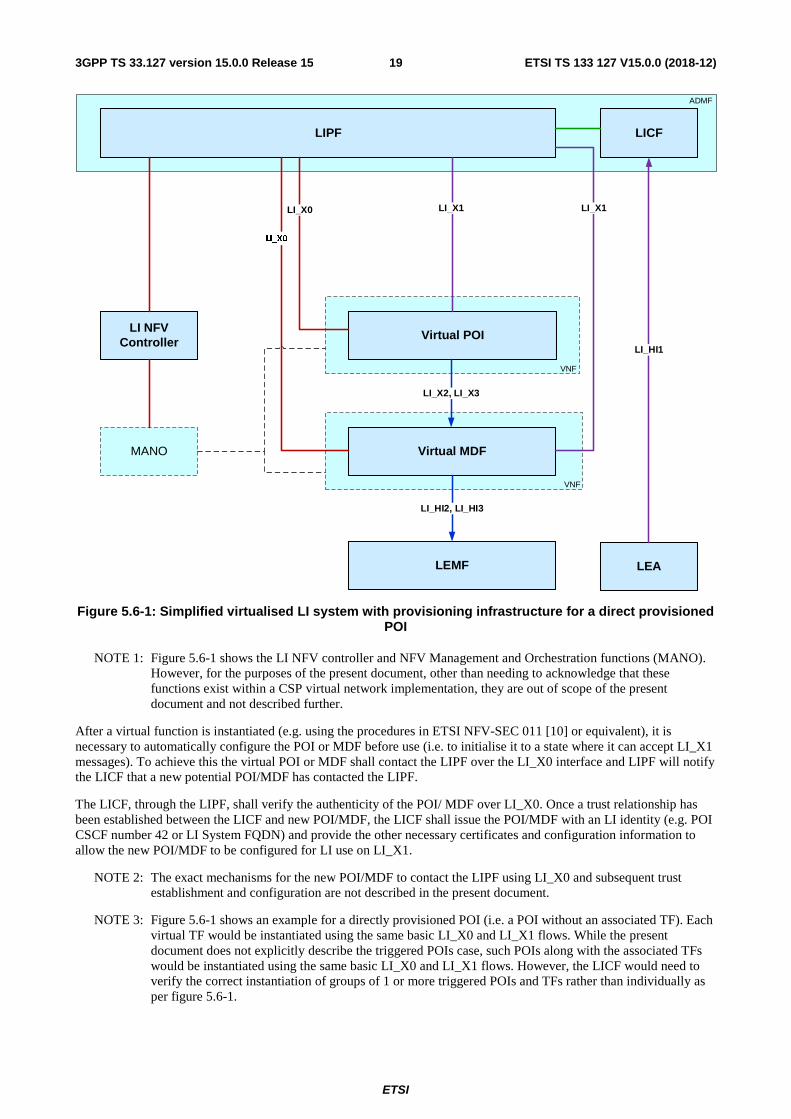
Figure 5.6-1 shows the necessary extensions to the basic LI architecture described in clause 5.2 required to support real-time deployment of virtualised LI functions. Figure 5.6-1 is a simplified version of the virtual LI function deployment procedures.
ETSI
ETSI TS 133 127 V15.0.0 (2018-12)193GPP TS 33.127 version 15.0.0 Release 15
LICF
Virtual MDF
Virtual POI
LIPF
LEMF LEA
LI_X1
LI_X2, LI_X3
LI_X1
LI_HI1
ADMF
VNF
VNF
LI_HI2, LI_HI3
LI NFV Controller
MANO
LI_X0
LI_X0
Figure 5.6-1: Simplified virtualised LI system with provisioning infrastructure for a direct provisioned POI
NOTE 1: Figure 5.6-1 shows the LI NFV controller and NFV Management and Orchestration functions (MANO). However, for the purposes of the present document, other than needing to acknowledge that these functions exist within a CSP virtual network implementation, they are out of scope of the present document and not described further.
After a virtual function is instantiated (e.g. using the procedures in ETSI NFV-SEC 011 [10] or equivalent), it is necessary to automatically configure the POI or MDF before use (i.e. to initialise it to a state where it can accept LI_X1 messages). To achieve this the virtual POI or MDF shall contact the LIPF over the LI_X0 interface and LIPF will notify the LICF that a new potential POI/MDF has contacted the LIPF.
The LICF, through the LIPF, shall verify the authenticity of the POI/ MDF over LI_X0. Once a trust relationship has been established between the LICF and new POI/MDF, the LICF shall issue the POI/MDF with an LI identity (e.g. POI CSCF number 42 or LI System FQDN) and provide the other necessary certificates and configuration information to allow the new POI/MDF to be configured for LI use on LI_X1.
NOTE 2: The exact mechanisms for the new POI/MDF to contact the LIPF using LI_X0 and subsequent trust establishment and configuration are not described in the present document.
NOTE 3: Figure 5.6-1 shows an example for a directly provisioned POI (i.e. a POI without an associated TF). Each virtual TF would be instantiated using the same basic LI_X0 and LI_X1 flows. While the present document does not explicitly describe the triggered POIs case, such POIs along with the associated TFs would be instantiated using the same basic LI_X0 and LI_X1 flows. However, the LICF would need to verify the correct instantiation of groups of 1 or more triggered POIs and TFs rather than individually as per figure 5.6-1.
ETSI
ETSI TS 133 127 V15.0.0 (2018-12)203GPP TS 33.127 version 15.0.0 Release 15
6 Network layer based interception
6.1 General Clause 6 gives details for the configuration of the high-level LI architecture for network layer based interception. It defines aspects of the LI configuration specific to each network under consideration (e.g. 5G), while aspects concerning services delivered over this network are considered in clause 7.
6.2 5G
6.2.1 General
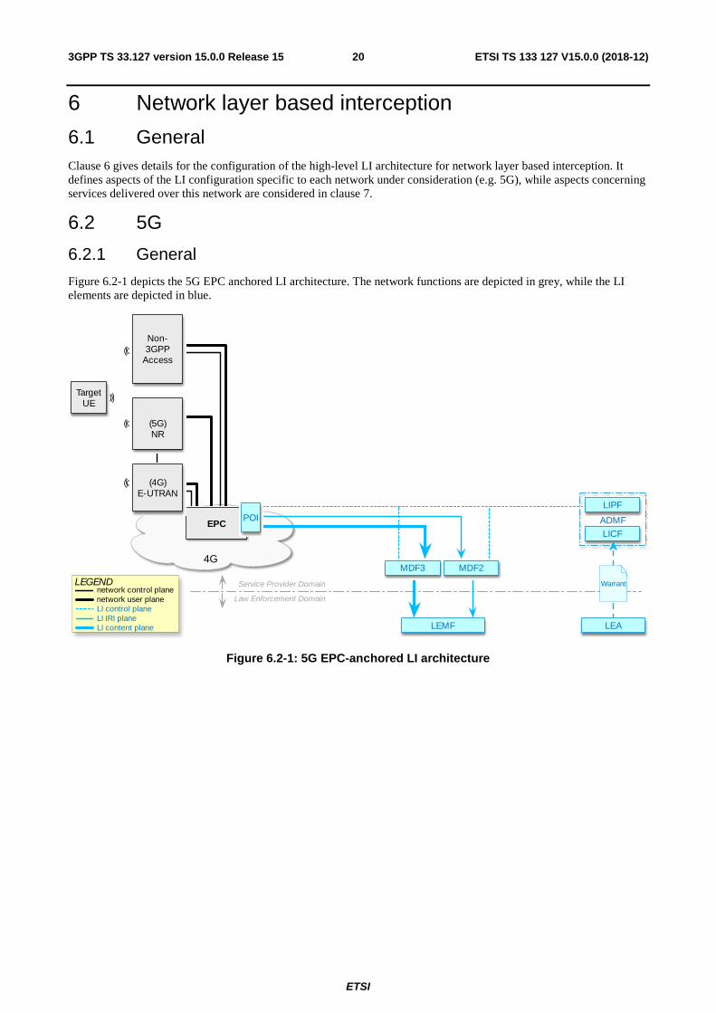
Figure 6.2-1 depicts the 5G EPC anchored LI architecture. The network functions are depicted in grey, while the LI elements are depicted in blue.
Figure 6.2-1: 5G EPC-anchored LI architecture
TargetUE
LEMF
4G
Service Provider Domain
Law Enforcement Domain
MDF3 MDF2
Non-3GPP
Access
LICF
LIPF
ADMF
Warrant
LEA
LEGEND
LI control planeLI IRI planeLI content plane
network control planenetwork user plane
EPCPOI
(4G)E-UTRAN
(5G)NR
ETSI
ETSI TS 133 127 V15.0.0 (2018-12)213GPP TS 33.127 version 15.0.0 Release 15
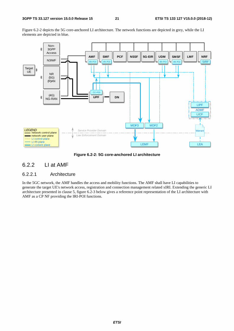
Figure 6.2-2 depicts the 5G core-anchored LI architecture. The network functions are depicted in grey, while the LI elements are depicted in blue.
Figure 6.2-2: 5G core-anchored LI architecture
6.2.2 LI at AMF
6.2.2.1 Architecture
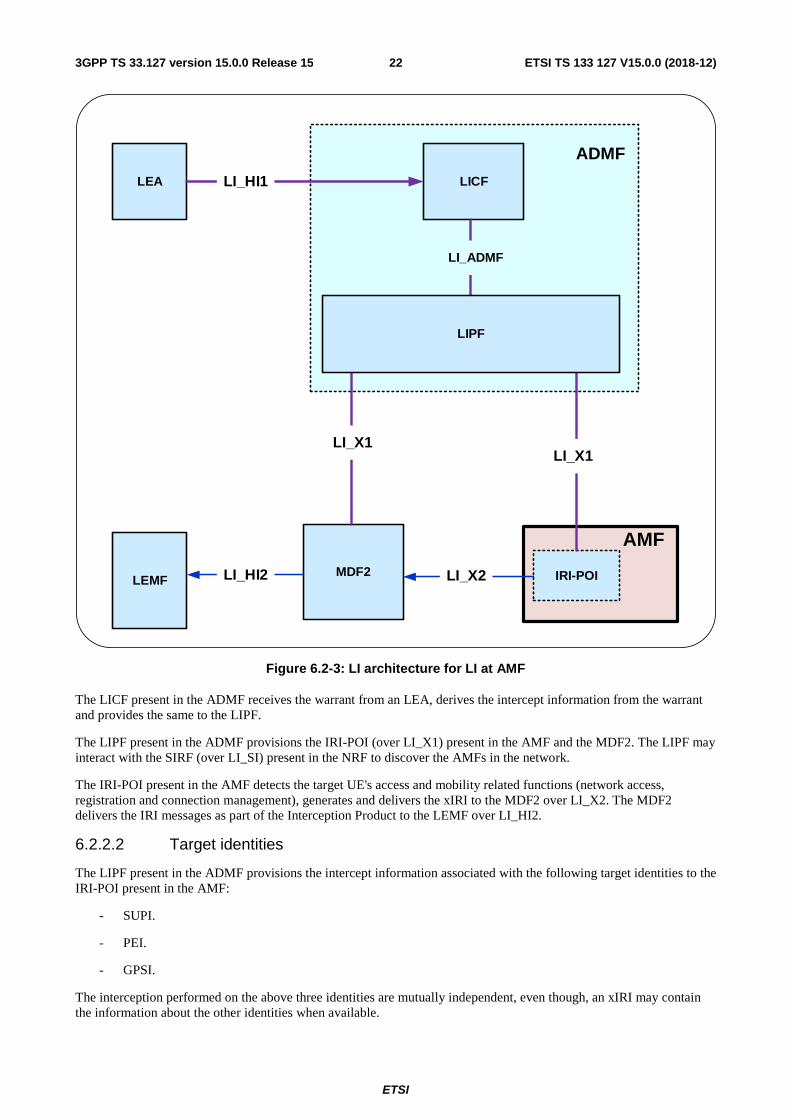
In the 5GC network, the AMF handles the access and mobility functions. The AMF shall have LI capabilities to generate the target UE's network access, registration and connection management related xIRI. Extending the generic LI architecture presented in clause 5, figure 6.2-3 below gives a reference point representation of the LI architecture with AMF as a CP NF providing the IRI-POI functions.
TargetUE
LEMF
NSSFSMF
IRI-POI
PCF 5G-EIRAMF
IRI-POI
UDM
IRI-POI
SMSF
DN
LMF NRF
SIRF
Service Provider Domain
Law Enforcement Domain
LEGEND
LI control planeLI IRI planeLI content plane
network control planenetwork user plane
MDF3 MDF2
Warrant
LEA
Non-3GPP
Access
(4G)NG-RAN
N3IWFIRI-POI
LICF
LIPF
ADMF
UPF
CC-POI
NR(5G)
(R)AN
ETSI
ETSI TS 133 127 V15.0.0 (2018-12)223GPP TS 33.127 version 15.0.0 Release 15
LEMFMDF2
AMF
IRI-POI
LICFLEA
LI_X1
LI_X2
LI_X1
LI_HI1
LI_ADMF
ADMF
LI_HI2
LIPF
Figure 6.2-3: LI architecture for LI at AMF
The LICF present in the ADMF receives the warrant from an LEA, derives the intercept information from the warrant and provides the same to the LIPF.
The LIPF present in the ADMF provisions the IRI-POI (over LI_X1) present in the AMF and the MDF2. The LIPF may interact with the SIRF (over LI_SI) present in the NRF to discover the AMFs in the network.
The IRI-POI present in the AMF detects the target UE's access and mobility related functions (network access, registration and connection management), generates and delivers the xIRI to the MDF2 over LI_X2. The MDF2 delivers the IRI messages as part of the Interception Product to the LEMF over LI_HI2.
6.2.2.2 Target identities
The LIPF present in the ADMF provisions the intercept information associated with the following target identities to the IRI-POI present in the AMF:
- SUPI.
- PEI.
- GPSI.
The interception performed on the above three identities are mutually independent, even though, an xIRI may contain the information about the other identities when available.
ETSI
ETSI TS 133 127 V15.0.0 (2018-12)233GPP TS 33.127 version 15.0.0 Release 15
6.2.2.3 Identity privacy
TS 33.501 [9] defines the ability to prevent the SUPI being exposed over the 5G RAN through the use of SUCI. Where SUPI privacy is implemented by both the UDM and UE, the SUPI is not sent in the clear over the RAN. Therefore, AMF has to rely on the UDM to provide the SUPI as part of the registration procedure as defined in TS 33.501.
If the AMF receives a SUCI from the UE then the AMF shall ensure for every registration (including re-registration) that SUPI has been provided by the UDM to the AMF and that the SUCI to SUPI mapping has been verified as defined in TS 33.501. This shall be performed regardless of whether the SUPI is a target of interception.
The AMF IRI-POI shall provide both the SUPI and the current SUCI in all applicable events defined in clause 6.2.2.4.
6.2.2.4 IRI events
The IRI-POI present in the AMF shall generate xIRI, when it detects the following specific events or information:
- Registration.
- Deregistration.
- Location update.
- Start of interception with already registered UE.
- Unsuccessful communication attempt.
NOTE: AMF reporting of UE state changes other than registration or deregistration is not supported in the present document.
The registration xIRI is generated when the IRI-POI present in an AMF detects that a target UE has successfully registered to the 5GS via 3GPP NG-RAN or non-3GPP access. The registration xIRI describes the type of registration performed (e.g. initial registration, periodic registration, registration mobility update) and the access type (e.g. 3GPP, non-3GPP). Unsuccessful registration shall be reported only if the target UE has been successfully authenticated.
The deregistration xIRI is generated when the IRI-POI present in an AMF detects that a target UE has deregistered from the 5GS. The deregistration xIRI shall indicate whether it was an UE-initiated or a network-initiated deregistration.
Location update xIRI is generated each time the IRI-POI present in an AMF detects that the target's UE location is updated due to target's UE mobility (e.g. in case of Xn based inter NG-RAN handover). The generation of such xIRI may be omitted if the updated UE location information is already included in other xIRIs (e.g. mobility registration) provided by the IRI-POI present in the same AMF.
The start of interception with already registered UE xIRI is generated when the IRI-POI present in an AMF detects that interception is activated on the target UE that has already been registered in the 5GS.
When additional warrants are activated on a target UE, MDF2 shall be able to generate and deliver the start of interception with already registered UE to the LEMF associated with the additional warrants without receiving a corresponding xIRI.
The unsuccessful communication attempt xIRI is generated when the IRI-POI present in an AMF detects that a target UE initiated communication procedure (e.g. session establishment, SMS) is rejected by the AMF before the proper NF handling the communication attempt itself is involved.
6.2.2.5 Common IRI parameters
The detailed list of xIRI parameters are specified in TS 33.128. All xIRI shall include the following:
- Target identity.
- Time stamp.
6.2.2.6 Specific IRI parameters
The detailed list of parameters in each xIRI are defined in TS 33.128. The following give a summary.
The registration xIRI shall include the following:
ETSI
ETSI TS 133 127 V15.0.0 (2018-12)243GPP TS 33.127 version 15.0.0 Release 15
- Registration type information.
- Access type information.
- Requested slice information.
The deregistration xIRI shall include the following:
- UE initiated de-registration.
- Access type information.
- Network initiated de-registration.
The location update xIRI shall include the following:
- Location of the target UE (see clause 7.3).
The start of interception with already registered UE xIRI shall include the following:
- Access type information.
- Requested slice information.
The unsuccessful communication attempt xIRI shall include the following:
- Rejected type of communication attempt.
- Access type information.
- Failure reason.
6.2.2.7 Network topologies
The AMF shall provide the IRI-POI functions in the following network topology cases:
- Non-roaming case.
- Roaming case, in VPLMN.
- Roaming case, in HPLMN for non-3GPP access.
In a roaming case, it is possible that the target UE may use non-3GPP access with the N3IWF present in the HPLMN.
6.2.3 LI for SMF/UPF
6.2.3.1 Architecture
In the 5GC network, user plane functions are separated from the control plane functions. The SMF that handles control plane actions (e.g. establishing, modifying, deleting) for the PDU sessions shall include an IRI-POI that has the LI capability to generate the related xIRI. The UPF that handles the user plane data shall include a CC-POI that has have the capability to duplicate the user plane packets from the PDU sessions based on the interception rules received from the SMF. Figure 6.2-4 shows the LI architecture for SMF/UPF based interception.
ETSI
ETSI TS 133 127 V15.0.0 (2018-12)253GPP TS 33.127 version 15.0.0 Release 15
LEMF
MDF2
MDF3
UPF
CC-POI
SMF
CC-TF
LIPF
LICFLEA
LI_X1
LI_X2
LI_X3LI_HI3
LI_X1LI_X1
LI_X1(management)
LI_HI1
LI_MDF
LI_ADMF
MDF
ADMF
LI_T3
LI_HI2IRI-POI
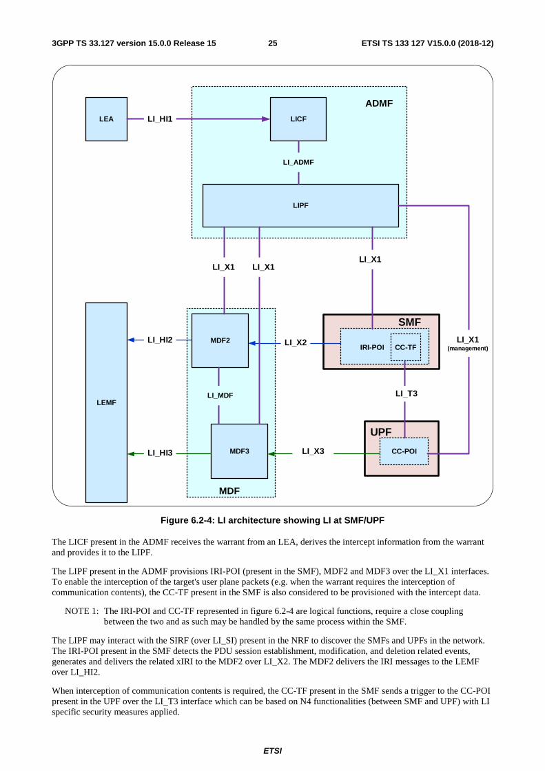
Figure 6.2-4: LI architecture showing LI at SMF/UPF
The LICF present in the ADMF receives the warrant from an LEA, derives the intercept information from the warrant and provides it to the LIPF.
The LIPF present in the ADMF provisions IRI-POI (present in the SMF), MDF2 and MDF3 over the LI_X1 interfaces. To enable the interception of the target's user plane packets (e.g. when the warrant requires the interception of communication contents), the CC-TF present in the SMF is also considered to be provisioned with the intercept data.
NOTE 1: The IRI-POI and CC-TF represented in figure 6.2-4 are logical functions, require a close coupling between the two and as such may be handled by the same process within the SMF.
The LIPF may interact with the SIRF (over LI_SI) present in the NRF to discover the SMFs and UPFs in the network. The IRI-POI present in the SMF detects the PDU session establishment, modification, and deletion related events, generates and delivers the related xIRI to the MDF2 over LI_X2. The MDF2 delivers the IRI messages to the LEMF over LI_HI2.
When interception of communication contents is required, the CC-TF present in the SMF sends a trigger to the CC-POI present in the UPF over the LI_T3 interface which can be based on N4 functionalities (between SMF and UPF) with LI specific security measures applied.
ETSI
ETSI TS 133 127 V15.0.0 (2018-12)263GPP TS 33.127 version 15.0.0 Release 15
The trigger sent from the CC-TF to CC-POI includes the following information:
- User plane packet detection rules.
- Target identity.
- Correlation number.
- MDF3 address.
NOTE 2: When LI_T3 is used, the LI_X1 between LIPF and CC-POI present in the UPF is used to monitor the user plane data.
The CC-POI present in the UPF generates the xCC from the user plane packets, and delivers the xCC (that includes the correlation number and the target identity) to the MDF3. The MDF3 delivers the CC to the LEMF over LI_HI3.
A warrant that does not require the interception of communication contents, may require IRI messages that have to be derived from the user plane packets. To support the generation of related xIRI (i.e. that requires access to the user plane packets), the present document supports two implementation approaches:
- In approach 1, the IRI-POI responsible for the generation of such xIRI resides in the UPF. Such an IRI-POI requires a trigger to enable it to detect the user plane packets. The corresponding Triggering Function (IRI-TF) resides in the same SMF that has the IRI-POI for the other xIRI.
- The trigger sent by the IRI-TF (present in the SMF) to the IRI-POI (present in the UPF) includes the following:
- User plane packet detection rules.
- Target identity.
- Correlation number.
- MDF2 address.
- The IRI-POI present in the UPF generates the xIRI (that includes the correlation number and the target identity) from the user plane packets and sends it to the MDF2. The MDF2 generates the IRI messages and send them to the LEMF.
- In approach 2, xCC is generated by the CC-POI present in the UPF as if the warrant involves the interception of communication contents. To enable this, the CC-TF presumed to be present in the SMF even when the warrant does not require the interception of communication contents. As explained before, the CC-POI generates the xCC and sends it to the MDF3. The MDF3 (based on the provisioned intercept information) does not generate and deliver the CC to the LEMF. Instead, the MDF3 forwards the xCC to the MDF2 over LI_MDF interface. The MDF2 then generates the IRI messages from xCC and delivers those IRI messages to the LEMF.
NOTE 3: The IRI-POI and IRI-TF present in the SMF may be handled by the same process in the SMF.
NOTE 4: When multiple warrants are active on a target with one requiring the interception of communication contents and the other not (in other words, this other one requiring xIRI from user plane packets), the first approach requires the UPF to have both CC-POI and IRI-POI and the SMF to have IRI-POI, IRI-TF and CC-TF. Alternatively, the interception of communication contents is required anyway for one warrant, and hence, the second approach will become simpler and therefore, may be preferable.
NOTE 5: Directly provisioned CC-POI is not considered in the present document.
6.2.3.2 Target identities
The LIPF provisions the intercept related information associated with the following target identities to the IRI-POI present in the SMF:
- SUPI.
- PEI.
- GPSI.
ETSI
ETSI TS 133 127 V15.0.0 (2018-12)273GPP TS 33.127 version 15.0.0 Release 15
The interception performed on the above three identities are mutually independent, even though, an xIRI may contain the information about the other identities when available.
6.2.3.3 IRI events
The IRI-POI present in the SMF shall generate xIRI, when it detects the following specific events or information:
- PDU session establishment.
- PDU session modification.
- PDU session release.
- Start of interception with an established PDU session.
PDU session establishment xIRI is generated when the IRI-POI present in the SMF detects that a PDU session has been established for the target UE.
PDU session modification xIRI is generated when the IRI-POI present in the SMF detects that a PDU session is modified for the target UE.
PDU session release xIRI is generated when the IRI-POI present in the SMF detects that a PDU session is released for the target UE.
The Start of Interception with an Established PDU Session xIRI is generated when the IRI-POI present in a SMF detects that interception is activated on the target UE that has an already established PDU session in the 5GS.
When a target UE has multiple PDU sessions, the above xIRI shall be sent for each PDU session with a different value of correlation information.
When the warrant requires the packet data header information reporting, the following xIRI shall be generated:
- Packet data header information report.
The generation of packet data information report can be done by either the IRI-POI present in the UPF or the MDF2.
6.2.3.4 Common IRI parameters
The list of xIRI parameters are specified in TS 33.128. Each xIRI shall include at the minimum the following information:
- Target identity.
- Time stamp.
- Correlation information.
- Location information.
- Session related information.
6.2.3.5 Specific IRI parameters
The parameters in each xIRI are defined in TS 33.128.
6.2.3.6 Network topologies
The SMF shall provide the IRI-POI functions in the following network topology cases:
- Non-roaming case.
- Roaming case, in VPLMN.
- Roaming case, in HPLMN.
- Non-3GPP access case, in the PLMN where N3IWF resides.
ETSI
ETSI TS 133 127 V15.0.0 (2018-12)283GPP TS 33.127 version 15.0.0 Release 15
When the target UE has multiple PDU sessions active, the generation and delivery of xCC for each PDU session shall be done independently, each with separate correlation information.
When a target UE's PDU session involves multiple Data Network (DN) connections, the generation and delivery of xCC shall be done in such a way that:
- All applicable user plane packets are captured and delivered.
- Duplicate delivery of CC is suppressed to the extent possible.
A PDU session may involve more than one UPFs. In that case, the CC-TF present in the SMF shall determine which UPF(s) is (are) more suitable to provide the CC-POI functions adhering to the above two requirements. Furthermore, independent of which UPF is used to generate the xCC, the CC delivered from the MDF3 shall be correlated to the IRI messages related to the PDU session.
6.2.4 LI at UDM for 5G
In 5G packet core network, the UDM provides the unified data management for UE. The UDM shall have LI capabilities to generate the target UE's service area registration related xIRI. See clause 7.2.2 for the details.
6.2.5 LI at SMSF
6.2.5.1 Architecture
In the 5GC network, the SMSF provides functionalities to support the SMS over NAS. The SMSF shall have LI capabilities to generate xIRIs when SMS related to the target's UE are handled. Extending the generic LI architecture presented in clause 5, figure 6.2-5 below gives a reference point representation of the LI architecture with SMSF as a CP NF providing the IRI-POI functions.
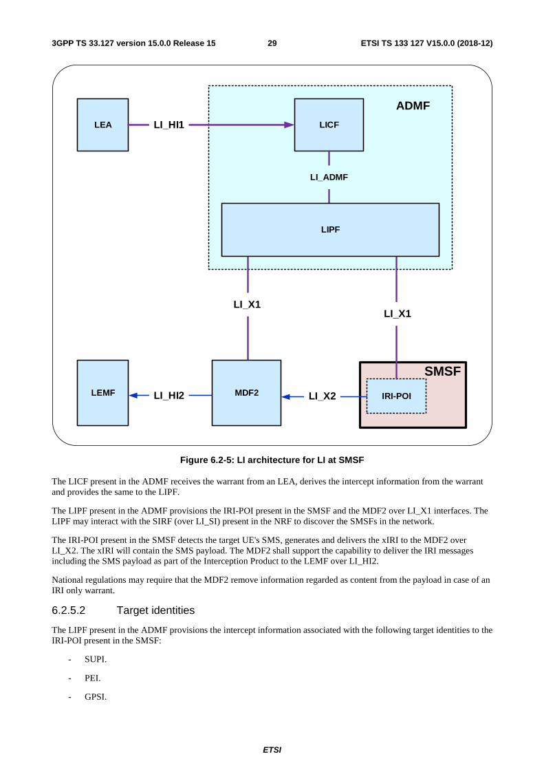
ETSI
ETSI TS 133 127 V15.0.0 (2018-12)293GPP TS 33.127 version 15.0.0 Release 15
LEMF
SMSF
IRI-POI
LICFLEA
LI_X1
LI_X2
LI_X1
LI_HI1
LI_ADMF
ADMF
LI_HI2
LIPF
MDF2
Figure 6.2-5: LI architecture for LI at SMSF
The LICF present in the ADMF receives the warrant from an LEA, derives the intercept information from the warrant and provides the same to the LIPF.
The LIPF present in the ADMF provisions the IRI-POI present in the SMSF and the MDF2 over LI_X1 interfaces. The LIPF may interact with the SIRF (over LI_SI) present in the NRF to discover the SMSFs in the network.
The IRI-POI present in the SMSF detects the target UE's SMS, generates and delivers the xIRI to the MDF2 over LI_X2. The xIRI will contain the SMS payload. The MDF2 shall support the capability to deliver the IRI messages including the SMS payload as part of the Interception Product to the LEMF over LI_HI2.
National regulations may require that the MDF2 remove information regarded as content from the payload in case of an IRI only warrant.
6.2.5.2 Target identities
The LIPF present in the ADMF provisions the intercept information associated with the following target identities to the IRI-POI present in the SMSF:
- SUPI.
- PEI.
- GPSI.
ETSI
ETSI TS 133 127 V15.0.0 (2018-12)303GPP TS 33.127 version 15.0.0 Release 15
The interception performed on the above three identities are mutually independent, even though, an xIRI may contain the information about the other identities when available.
6.2.5.3 IRI events
The IRI-POI present in the SMSF shall generate xIRI, when it detects the following specific events or information:
- SMS.
The SMS xIRI is generated when the IRI-POI present in an SMSF detects that a SMS for the target UE is handled.
6.2.5.4 Common IRI parameters
The list of xIRI parameters are specified in TS 33.128. The xIRIs shall include at the minimum the following information:
- Target identity.
- Time stamp.
- Location information.
- SMS direction (mobile originated, mobile yerminated).
- SMS payload.
6.2.5.5 Specific IRI parameters
The parameters in each xIRI are defined in TS 33.128.
6.2.5.6 Network topologies
The SMSF shall provide the IRI-POI functions in the following network topology cases:
- Non-roaming case.
- Roaming case, in VPLMN.
NOTE: SMS delivery over non-3GPP access with N3IWF in the HPLMN is considered a non-roaming case.
6.2.6 LI support at NRF
6.2.6.1 Architecture
In 5G, network functions that support SBA register with the NRF after instantiation. The NRF thus provides the network repository functions and is aware of all the NFs that have been instantiated. The present document refers to this as system information.
The SIRF present in the NRF provides the system information to LIPF present in the ADMF, in order for the LIPF to establish which NFs (and therefore POIs) are applicable to a specific target user's services. LI function service discovery is described in clause 5.5.
An architecture diagram depicting this LI at NRF is shown in figure 6.2-6 below.
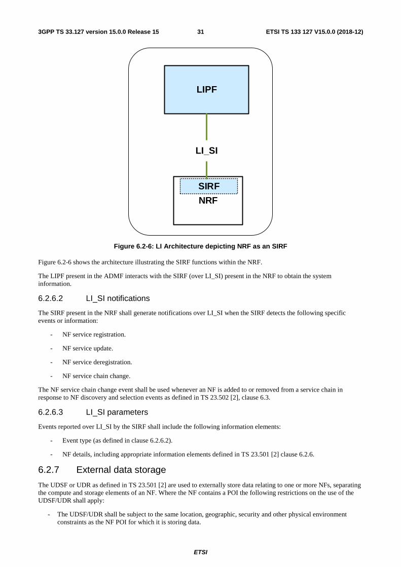
ETSI
ETSI TS 133 127 V15.0.0 (2018-12)313GPP TS 33.127 version 15.0.0 Release 15
LIPF
NRF
SIRF
LI_SI
Figure 6.2-6: LI Architecture depicting NRF as an SIRF
Figure 6.2-6 shows the architecture illustrating the SIRF functions within the NRF.
The LIPF present in the ADMF interacts with the SIRF (over LI_SI) present in the NRF to obtain the system information.
6.2.6.2 LI_SI notifications
The SIRF present in the NRF shall generate notifications over LI_SI when the SIRF detects the following specific events or information:
- NF service registration.
- NF service update.
- NF service deregistration.
- NF service chain change.
The NF service chain change event shall be used whenever an NF is added to or removed from a service chain in response to NF discovery and selection events as defined in TS 23.502 [2], clause 6.3.
6.2.6.3 LI_SI parameters
Events reported over LI_SI by the SIRF shall include the following information elements:
- Event type (as defined in clause 6.2.6.2).
- NF details, including appropriate information elements defined in TS 23.501 [2] clause 6.2.6.
6.2.7 External data storage
The UDSF or UDR as defined in TS 23.501 [2] are used to externally store data relating to one or more NFs, separating the compute and storage elements of an NF. Where the NF contains a POI the following restrictions on the use of the UDSF/UDR shall apply:
- The UDSF/UDR shall be subject to the same location, geographic, security and other physical environment constraints as the NF POI for which it is storing data.
ETSI
ETSI TS 133 127 V15.0.0 (2018-12)323GPP TS 33.127 version 15.0.0 Release 15
- No LI specific POI data (e.g. target list) shall be stored in the UDSF/UDR unless storage is directly under the control of the POI within the NF.
- LI data stored in a UDSF/UDR shall only be accessible by the specific individual POI for which the UDSF/UDR is storing data and that data shall not be shared between POIs unless specifically authorised by the LICF within the ADMF.
- By default, LI data shall not be stored in a UDSF/UDR which is shared by multiple NFs unless specifically authorised by the LICF.
- Any storage of LI data outside of the POI in the UDSF/UDR shall be auditable by the LICF.
- The interface between the POI/NF and the UDSF/UDR shall be protected such that an attacker cannot identify targeted users based on observation of this interface. (i.e. access to the UDSF/UDR shall be identical for both intercepted and non-intercepted user communications).
- The use and placement of a UDSF/UDR within an NF/POI design shall not introduce additional interception delay compared with non-separated compute and storage.
- Where the POI requires access to NF data that is stored in the UDSF/UDR, non-LI network functions and processes or non-LI authorised personnel shall not be able to detect POI access to that data in the UDSF/UDR.
- The POI and LICF/MDF shall be responsible for managing encryption of LI data stored for the POI in addition to any default encryption applied by the NF.
The above requirements shall apply when the UDSF/UDR provide data storage for TF/NF.
6.3 4G The Present document does not specify LI functionality for 4G / LTE. LI capabilities for 4G / LTE for this release are specified in TS 33.107 [11].
6.4 3G The Present document does not specify LI functionality for 3G / UMTS. LI capabilities for 3G / UMTS for this release are specified in TS 33.107 [11].
7 Service layer based interception
7.1 General Clause 7 provides details for the configuration of the high-level LI architecture for service layer based interception. It defines aspects of the LI configuration specific to each service under consideration, while aspects concerning network over which the service is delivered (e.g. 5G) are considered in clause 6.
7.2 Central subscriber management
7.2.1 General
Clause 7.2 provides LI architecture and requirements for the CSP 3GPP subscriber database LI reporting. Central subscriber databases are common for all CSP network services, including both the network layer and the service layer. This Clause 7.2 provides requirements for both user session related interception events and requirements for reporting of changes to the subscriber information held within the 3GPP subscriber databases, which may or may not be directly related to service usage.
7.2.2 LI at UDM
7.2.2.1 Architecture
The UDM provides the unified data management for UE. The UDM shall have LI capabilities to generate the target UE's serving system (e.g. VPLMN Id or AMF Id related xIRI). Extending the generic LI architecture presented in
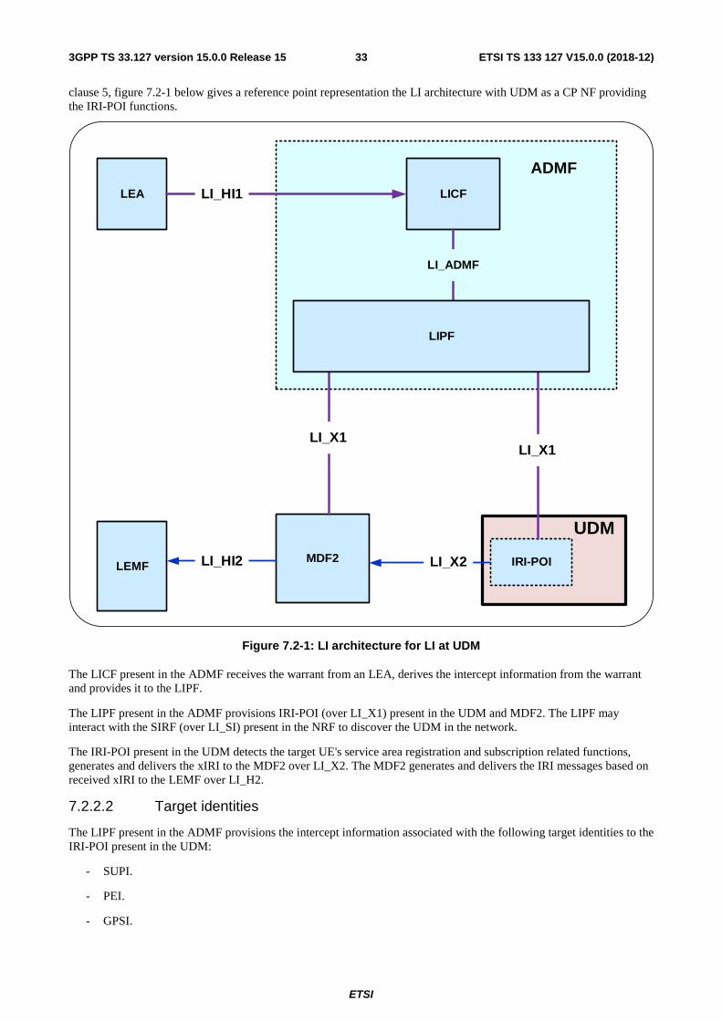
ETSI
ETSI TS 133 127 V15.0.0 (2018-12)333GPP TS 33.127 version 15.0.0 Release 15
clause 5, figure 7.2-1 below gives a reference point representation the LI architecture with UDM as a CP NF providing the IRI-POI functions.
LEMFMDF2
UDM
IRI-POI
LICFLEA
LI_X1
LI_X2
LI_X1
LI_HI1
LI_ADMF
ADMF
LI_HI2
LIPF
Figure 7.2-1: LI architecture for LI at UDM
The LICF present in the ADMF receives the warrant from an LEA, derives the intercept information from the warrant and provides it to the LIPF.
The LIPF present in the ADMF provisions IRI-POI (over LI_X1) present in the UDM and MDF2. The LIPF may interact with the SIRF (over LI_SI) present in the NRF to discover the UDM in the network.
The IRI-POI present in the UDM detects the target UE's service area registration and subscription related functions, generates and delivers the xIRI to the MDF2 over LI_X2. The MDF2 generates and delivers the IRI messages based on received xIRI to the LEMF over LI_H2.
7.2.2.2 Target identities
The LIPF present in the ADMF provisions the intercept information associated with the following target identities to the IRI-POI present in the UDM:
- SUPI.
- PEI.
- GPSI.
ETSI
ETSI TS 133 127 V15.0.0 (2018-12)343GPP TS 33.127 version 15.0.0 Release 15
- IMPU/IMPI.
The interception performed on the above identities are mutually independent, even though, an xIRI may contain the information about the other identities when available.
7.2.2.3 Identity privacy
TS 33.501 [9] defines the ability to prevent the SUPI being exposed over the 5G RAN through the use of SUCI. Where SUPI privacy is implemented by both the UDM and UE, the SUPI is not sent in the clear over the RAN. Therefore, the UDM shall ensure that the SUPI is provided to the serving AMF in both initial registration and re-registration procedures as defined in TS 33.501.
The UDM IRI-POI shall provide both the SUPI and the current SUCI in all applicable events defined in clause 7.2.2.4.
7.2.2.4 IRI events
The IRI-POI present in the UDM shall generate xIRI, when the UDM detects the following specific events or information:
- Serving system.
- Subscriber record change.
- Cancel location.
- Location information request.
A serving system xIRI is generated when the IRI-POI present in the UDM detects the target UE registration or re-registration related notifications. The AMF Id or the MME Id, or the VPLMN Id (when the other two are not known) is used as the serving system identifier in a serving system xIRI.
NOTE: The serving system xIRI may carry the information of one or more serving systems based on the target UE's network connectivity.
A subscriber record change xIRI is generated when the IRI-POI present in the UDM detects that the associated GPSI, or SUPI, or PEI is changed.
A cancel location xIRI is generated when the IRI-POI present in the UDM detects that a de-registration notification is sent, or received, by the UDM.
A location information request xIRI is generated when the IRI-POI present in the UDM detects that the UDM receiving a query for the location information of the target UE from a different PLMN (e.g. inbound SMS routing) with a known PLMN Id.
7.2.2.5 Common IRI parameters
The list of xIRI parameters are specified in TS 33.128. All xIRIs shall include the following information:
- Target identity.
- Time stamp.
7.2.2.6 Specific IRI parameters
The parameters in each xIRI are defined in TS 33.128.
7.2.2.7 Network topologies
The UDM shall provide the IRI-POI functions in the following network topology cases:
- Non-roaming case.
- Roaming case, in HPLMN.
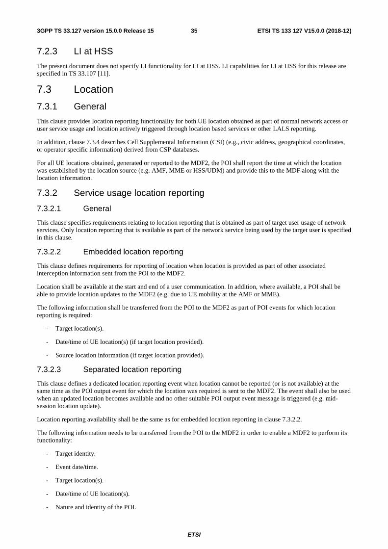
ETSI
ETSI TS 133 127 V15.0.0 (2018-12)353GPP TS 33.127 version 15.0.0 Release 15
7.2.3 LI at HSS
The present document does not specify LI functionality for LI at HSS. LI capabilities for LI at HSS for this release are specified in TS 33.107 [11].
7.3 Location
7.3.1 General
This clause provides location reporting functionality for both UE location obtained as part of normal network access or user service usage and location actively triggered through location based services or other LALS reporting.
In addition, clause 7.3.4 describes Cell Supplemental Information (CSI) (e.g., civic address, geographical coordinates, or operator specific information) derived from CSP databases.
For all UE locations obtained, generated or reported to the MDF2, the POI shall report the time at which the location was established by the location source (e.g. AMF, MME or HSS/UDM) and provide this to the MDF along with the location information.
7.3.2 Service usage location reporting
7.3.2.1 General
This clause specifies requirements relating to location reporting that is obtained as part of target user usage of network services. Only location reporting that is available as part of the network service being used by the target user is specified in this clause.
7.3.2.2 Embedded location reporting
This clause defines requirements for reporting of location when location is provided as part of other associated interception information sent from the POI to the MDF2.
Location shall be available at the start and end of a user communication. In addition, where available, a POI shall be able to provide location updates to the MDF2 (e.g. due to UE mobility at the AMF or MME).
The following information shall be transferred from the POI to the MDF2 as part of POI events for which location reporting is required:
- Target location(s).
- Date/time of UE location(s) (if target location provided).
- Source location information (if target location provided).
7.3.2.3 Separated location reporting
This clause defines a dedicated location reporting event when location cannot be reported (or is not available) at the same time as the POI output event for which the location was required is sent to the MDF2. The event shall also be used when an updated location becomes available and no other suitable POI output event message is triggered (e.g. mid- session location update).
Location reporting availability shall be the same as for embedded location reporting in clause 7.3.2.2.
The following information needs to be transferred from the POI to the MDF2 in order to enable a MDF2 to perform its functionality:
- Target identity.
- Event date/time.
- Target location(s).
- Date/time of UE location(s).
- Nature and identity of the POI.
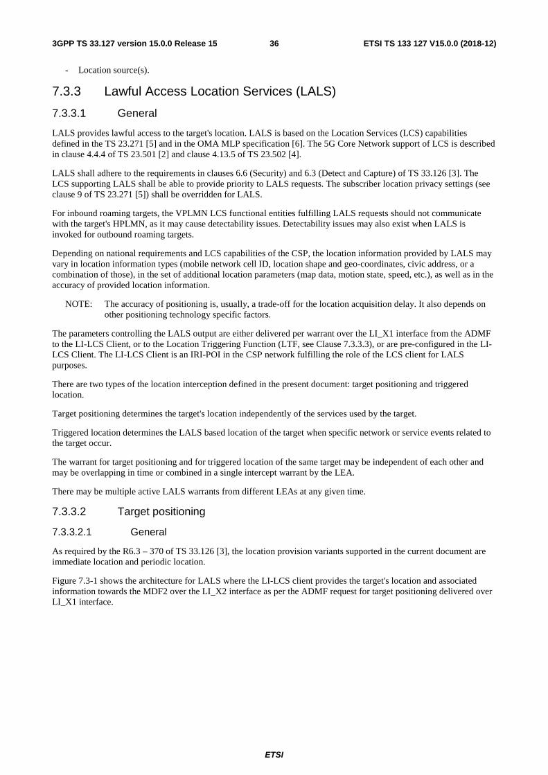
ETSI
ETSI TS 133 127 V15.0.0 (2018-12)363GPP TS 33.127 version 15.0.0 Release 15
- Location source(s).
7.3.3 Lawful Access Location Services (LALS)
7.3.3.1 General
LALS provides lawful access to the target's location. LALS is based on the Location Services (LCS) capabilities defined in the TS 23.271 [5] and in the OMA MLP specification [6]. The 5G Core Network support of LCS is described in clause 4.4.4 of TS 23.501 [2] and clause 4.13.5 of TS 23.502 [4].
LALS shall adhere to the requirements in clauses 6.6 (Security) and 6.3 (Detect and Capture) of TS 33.126 [3]. The LCS supporting LALS shall be able to provide priority to LALS requests. The subscriber location privacy settings (see clause 9 of TS 23.271 [5]) shall be overridden for LALS.
For inbound roaming targets, the VPLMN LCS functional entities fulfilling LALS requests should not communicate with the target's HPLMN, as it may cause detectability issues. Detectability issues may also exist when LALS is invoked for outbound roaming targets.
Depending on national requirements and LCS capabilities of the CSP, the location information provided by LALS may vary in location information types (mobile network cell ID, location shape and geo-coordinates, civic address, or a combination of those), in the set of additional location parameters (map data, motion state, speed, etc.), as well as in the accuracy of provided location information.
NOTE: The accuracy of positioning is, usually, a trade-off for the location acquisition delay. It also depends on other positioning technology specific factors.
The parameters controlling the LALS output are either delivered per warrant over the LI_X1 interface from the ADMF to the LI-LCS Client, or to the Location Triggering Function (LTF, see Clause 7.3.3.3), or are pre-configured in the LI-LCS Client. The LI-LCS Client is an IRI-POI in the CSP network fulfilling the role of the LCS client for LALS purposes.
There are two types of the location interception defined in the present document: target positioning and triggered location.
Target positioning determines the target's location independently of the services used by the target.
Triggered location determines the LALS based location of the target when specific network or service events related to the target occur.
The warrant for target positioning and for triggered location of the same target may be independent of each other and may be overlapping in time or combined in a single intercept warrant by the LEA.
There may be multiple active LALS warrants from different LEAs at any given time.
7.3.3.2 Target positioning
7.3.3.2.1 General
As required by the R6.3 – 370 of TS 33.126 [3], the location provision variants supported in the current document are immediate location and periodic location.
Figure 7.3-1 shows the architecture for LALS where the LI-LCS client provides the target's location and associated information towards the MDF2 over the LI_X2 interface as per the ADMF request for target positioning delivered over LI_X1 interface.
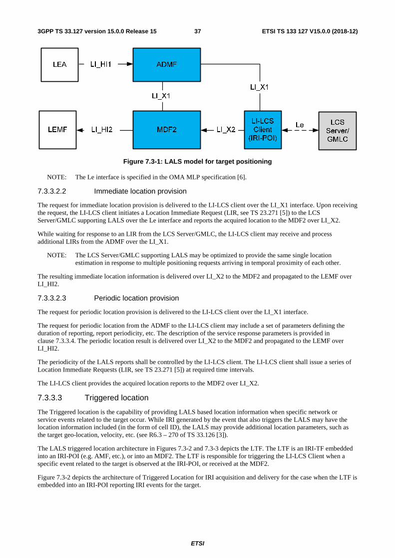
ETSI
ETSI TS 133 127 V15.0.0 (2018-12)373GPP TS 33.127 version 15.0.0 Release 15
Figure 7.3-1: LALS model for target positioning
NOTE: The Le interface is specified in the OMA MLP specification [6].
7.3.3.2.2 Immediate location provision
The request for immediate location provision is delivered to the LI-LCS client over the LI_X1 interface. Upon receiving the request, the LI-LCS client initiates a Location Immediate Request (LIR, see TS 23.271 [5]) to the LCS Server/GMLC supporting LALS over the Le interface and reports the acquired location to the MDF2 over LI_X2.
While waiting for response to an LIR from the LCS Server/GMLC, the LI-LCS client may receive and process additional LIRs from the ADMF over the LI_X1.
NOTE: The LCS Server/GMLC supporting LALS may be optimized to provide the same single location estimation in response to multiple positioning requests arriving in temporal proximity of each other.
The resulting immediate location information is delivered over LI_X2 to the MDF2 and propagated to the LEMF over LI_HI2.
7.3.3.2.3 Periodic location provision
The request for periodic location provision is delivered to the LI-LCS client over the LI_X1 interface.
The request for periodic location from the ADMF to the LI-LCS client may include a set of parameters defining the duration of reporting, report periodicity, etc. The description of the service response parameters is provided in clause 7.3.3.4. The periodic location result is delivered over LI_X2 to the MDF2 and propagated to the LEMF over LI_HI2.
The periodicity of the LALS reports shall be controlled by the LI-LCS client. The LI-LCS client shall issue a series of Location Immediate Requests (LIR, see TS 23.271 [5]) at required time intervals.
The LI-LCS client provides the acquired location reports to the MDF2 over LI_X2.
7.3.3.3 Triggered location
The Triggered location is the capability of providing LALS based location information when specific network or service events related to the target occur. While IRI generated by the event that also triggers the LALS may have the location information included (in the form of cell ID), the LALS may provide additional location parameters, such as the target geo-location, velocity, etc. (see R6.3 – 270 of TS 33.126 [3]).
The LALS triggered location architecture in Figures 7.3-2 and 7.3-3 depicts the LTF. The LTF is an IRI-TF embedded into an IRI-POI (e.g. AMF, etc.), or into an MDF2. The LTF is responsible for triggering the LI-LCS Client when a specific event related to the target is observed at the IRI-POI, or received at the MDF2.
Figure 7.3-2 depicts the architecture of Triggered Location for IRI acquisition and delivery for the case when the LTF is embedded into an IRI-POI reporting IRI events for the target.
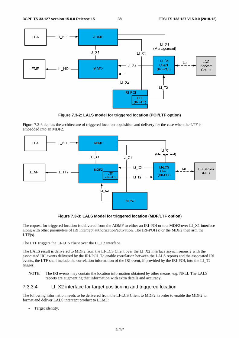
ETSI
ETSI TS 133 127 V15.0.0 (2018-12)383GPP TS 33.127 version 15.0.0 Release 15
Figure 7.3-2: LALS model for triggered location (POI/LTF option)
Figure 7.3-3 depicts the architecture of triggered location acquisition and delivery for the case when the LTF is embedded into an MDF2.
Figure 7.3-3: LALS Model for triggered location (MDF/LTF option)
The request for triggered location is delivered from the ADMF to either an IRI-POI or to a MDF2 over LI_X1 interface along with other parameters of IRI intercept authorization/activation. The IRI-POI (s) or the MDF2 then arm the LTF(s).
The LTF triggers the LI-LCS client over the LI_T2 interface.
The LALS result is delivered to MDF2 from the LI-LCS Client over the LI_X2 interface asynchronously with the associated IRI events delivered by the IRI-POI. To enable correlation between the LALS reports and the associated IRI events, the LTF shall include the correlation information of the IRI event, if provided by the IRI-POI, into the LI_T2 trigger.
NOTE: The IRI events may contain the location information obtained by other means, e.g. NPLI. The LALS reports are augmenting that information with extra details and accuracy.
7.3.3.4 LI_X2 interface for target positioning and triggered location
The following information needs to be delivered from the LI-LCS Client to MDF2 in order to enable the MDF2 to format and deliver LALS intercept product to LEMF:
- Target identity.
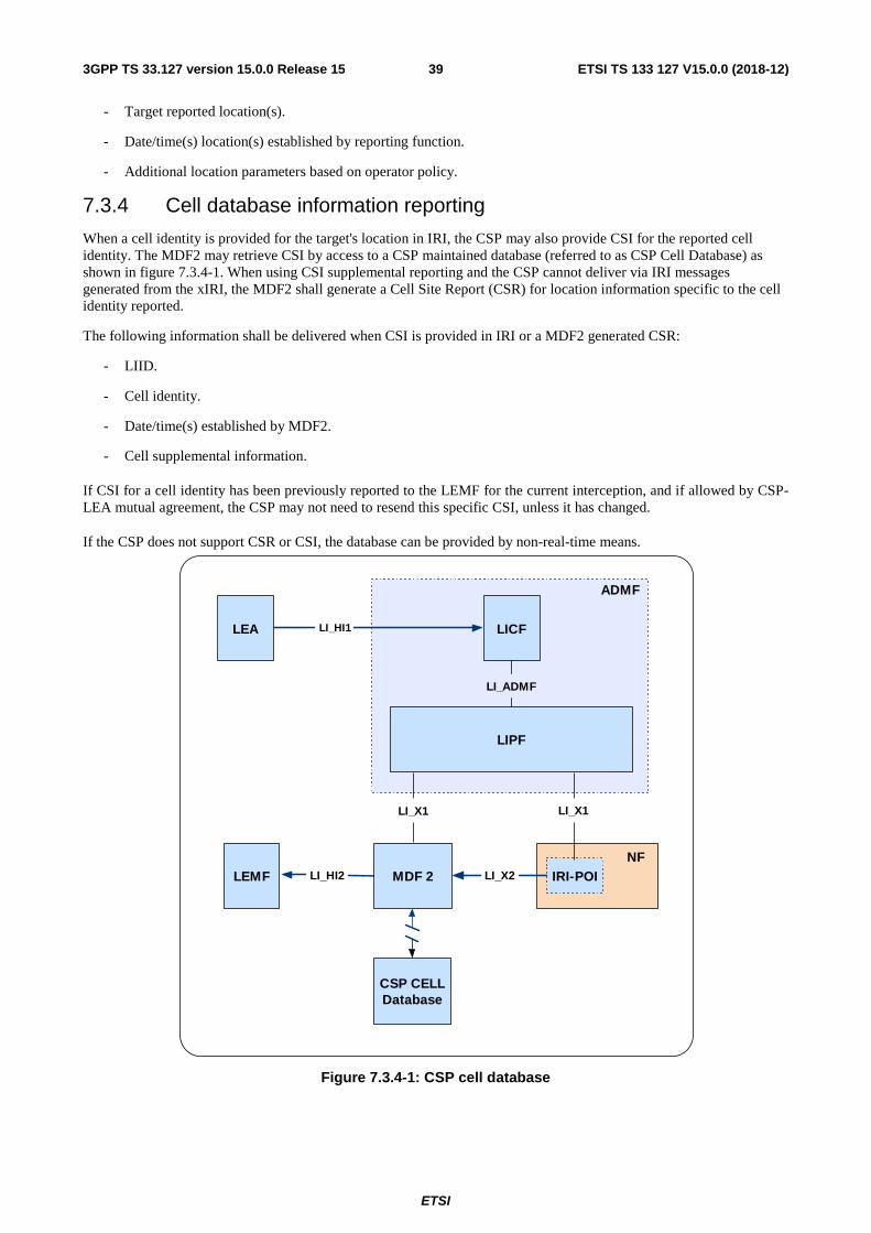
ETSI
ETSI TS 133 127 V15.0.0 (2018-12)393GPP TS 33.127 version 15.0.0 Release 15
- Target reported location(s).
- Date/time(s) location(s) established by reporting function.
- Additional location parameters based on operator policy.
7.3.4 Cell database information reporting
When a cell identity is provided for the target's location in IRI, the CSP may also provide CSI for the reported cell identity. The MDF2 may retrieve CSI by access to a CSP maintained database (referred to as CSP Cell Database) as shown in figure 7.3.4-1. When using CSI supplemental reporting and the CSP cannot deliver via IRI messages generated from the xIRI, the MDF2 shall generate a Cell Site Report (CSR) for location information specific to the cell identity reported.
The following information shall be delivered when CSI is provided in IRI or a MDF2 generated CSR:
- LIID.
- Cell identity.
- Date/time(s) established by MDF2.
- Cell supplemental information.
If CSI for a cell identity has been previously reported to the LEMF for the current interception, and if allowed by CSP-LEA mutual agreement, the CSP may not need to resend this specific CSI, unless it has changed.
If the CSP does not support CSR or CSI, the database can be provided by non-real-time means.
Figure 7.3.4-1: CSP cell database
LEMF IRI-POI
ADMF
LICF
LIPF
LEA
LI_ADMF
LI_HI1
LI_HI2 MDF 2 LI_X2
LI_X1LI_X1
CSP CELLDatabase
NF
ETSI
ETSI TS 133 127 V15.0.0 (2018-12)403GPP TS 33.127 version 15.0.0 Release 15
8 LI security considerations
8.1 Introduction The most sensitive information in the LI system is the target list. This is the list of all the subjects in the network currently under surveillance, whether active, suspended or in any other state. The security measures used by the carrier to ensure unauthorized access to this list is not subject to standardization, but the architectural choices made in the design of the LI system do impact the security of the target list directly.
Since completeness of the interception product is a legal requirement in most jurisdictions, the LI system shall ensure that no events that are lawfully authorized for interception are missed (or collected in error). To ensure that no events are missed there are two architectural alternatives.
8.2 Architectural alternatives
8.2.1 Full target list at every POI node
A carrier may choose to deploy the full target list at all POIs, such that when a UE arrives in the network and commences registration, the POI is fully armed and in position to recognize if the target identifier is in the target list. The choice to push the full list to every node is the simplest, and arguably the riskiest, since the compromise of any node will leak the complete target list.
8.2.2 Full target list only in LICF
A Communication Service Provider (CSP) may choose to selectively distribute specific target identifiers to specific POIs, rather than distributing the full target list to all POIs. This choice introduces a race condition. When the UE appears, the POI shall query the ADMF/LICF to find out if the user identifier is part of the target list. As the registration sequence progresses, the NF POI is waiting for a response from the ADMF/LICF. When the reply arrives, the POI can now take action if the reply was positive. If the reply is negative, the POI's involvement ends.
If the reply is positive, depending on how long the POI-(ADMF/LICF)-POI round trip for the query/reply took, it is possible that some reportable events are missed. To mitigate this there are two further alternatives:
1) the carrier may choose to delay completion of the registration for all users for the time it takes the ADMF/LICF to answer, thus inducing a registration delay in all registrations, whether the user is a target or not, or
2) the carrier may choose to cache the reportable registration events while the POI-(ADMF/LICF)-POI query is running, and either report them if the answer is positive, or delete them if the answer is negative.
These are choices at the discretion of the CSP, but the trade-off cannot be avoided.
8.2.3 Provisioning for registered users
When a new target is provisioned in the LI system, after the target is already registered in the CSP network, the CSP will be faced with the race condition consequences of the implementation choice made as described in clauses 8.2.1 and 8.2.2. The ADMF has a choice to either wholesale pre-arm every POI with the new target (and expect every POI to immediately start interception on the new target, as in clause 8.2.1), or, the ADMF can poll every serving UDM POI for all target UEs, and arm the associated POI (and start interception, as in clause 8.1.2) only if a target UE is discovered to be served by that particular NF. The second approach would take comparatively longer and would be expected to miss more of the on-going target interactions with the network than the first approach.
8.3 LI key management at ADMF
8.3.1 General
The ADMF is responsible for overall management of the LI system as defined in clause 5.3.2.4. The ADMF is responsible for creating and managing intermediate, client and root certificates used for both identity verification and establishing encrypted communications between LI components.
NOTE: The exact mechanism for installation of certificates in POIs, MDFs or other LI components (manual or automated) is outside the scope of the present document.
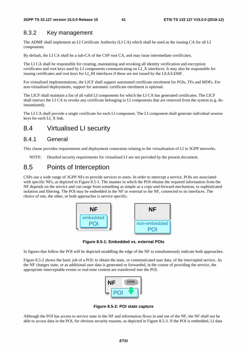
ETSI
ETSI TS 133 127 V15.0.0 (2018-12)413GPP TS 33.127 version 15.0.0 Release 15
8.3.2 Key management
The ADMF shall implement an LI Certificate Authority (LI CA) which shall be used as the issuing CA for all LI components.
By default, the LI CA shall be a sub-CA of the CSP root CA, and may issue intermediate certificates.
The LI CA shall be responsible for creating, maintaining and revoking all identity verification and encryption certificates and root keys used by LI components communicating on LI_X interfaces. It may also be responsible for issuing certificates and root keys for LI_HI interfaces if these are not issued by the LEA/LEMF.
For virtualised implementations, the LICF shall support automated certificate enrolment for POIs, TFs and MDFs. For non-virtualised deployments, support for automatic certificate enrolment is optional.
The LICF shall maintain a list of all valid LI components for which the LI CA has generated certificates. The LICF shall instruct the LI CA to revoke any certificate belonging to LI components that are removed from the system (e.g. de-instantiated).
The LI CA shall provide a single certificate for each LI component. The LI component shall generate individual session keys for each LI_X link.
8.4 Virtualised LI security
8.4.1 General
This clause provides requirements and deployment constraints relating to the virtualisation of LI in 3GPP networks.
NOTE: Detailed security requirements for virtualised LI are not provided by the present document.
8.5 Points of Interception CSPs use a wide range of 3GPP NFs to provide services to users. In order to intercept a service, POIs are associated with specific NFs, as depicted in Figure 8.5-1. The manner in which the POI obtains the required information from the NF depends on the service and can range from something as simple as a copy-and-forward mechanism, to sophisticated isolation and filtering. The POI may be embedded in the NF or external to the NF, connected to its interfaces. The choice of one, the other, or both approaches is service specific.
Figure 8.5-1: Embedded vs. external POIs
In figures that follow the POI will be depicted straddling the edge of the NF to simultaneously indicate both approaches.
Figure 8.5-2 shows the basic job of a POI: to obtain the state, or communicated user data, of the intercepted service. As the NF changes state, or as additional user data is generated or forwarded, in the course of providing the service, the appropriate interceptable events or real-time content are transferred into the POI.
Figure 8.5-2: POI state capture
Although the POI has access to service state in the NF and information flows in and out of the NF, the NF shall not be able to access data in the POI, for obvious security reasons, as depicted in Figure 8.5-3. If the POI is embedded, LI data
NF
non-embeddedPOI
NFembedded
POI
NF
POI
state
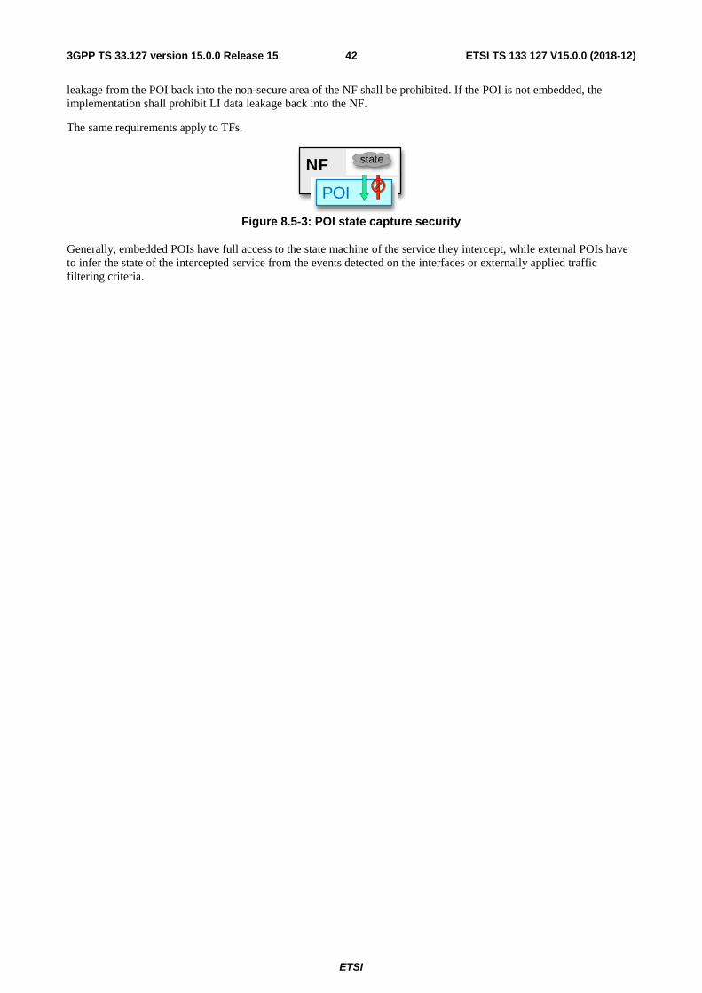
ETSI
ETSI TS 133 127 V15.0.0 (2018-12)423GPP TS 33.127 version 15.0.0 Release 15
leakage from the POI back into the non-secure area of the NF shall be prohibited. If the POI is not embedded, the implementation shall prohibit LI data leakage back into the NF.
The same requirements apply to TFs.
Figure 8.5-3: POI state capture security
Generally, embedded POIs have full access to the state machine of the service they intercept, while external POIs have to infer the state of the intercepted service from the events detected on the interfaces or externally applied traffic filtering criteria.
NF
POI
state
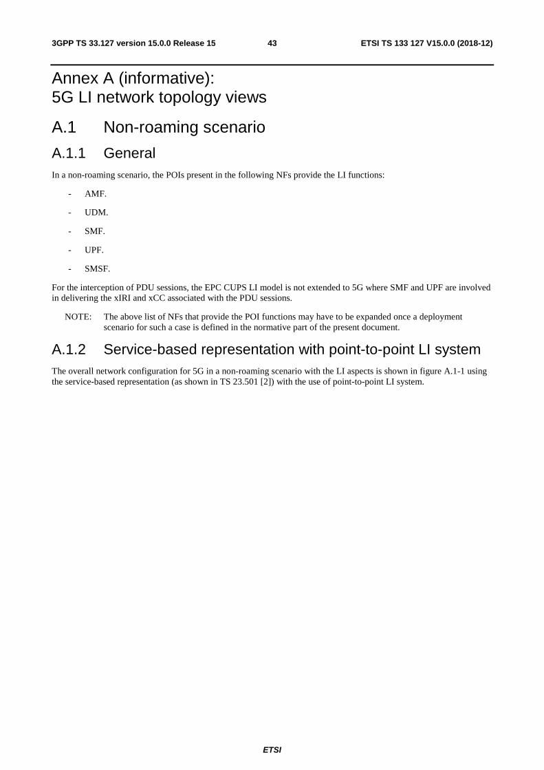
ETSI
ETSI TS 133 127 V15.0.0 (2018-12)433GPP TS 33.127 version 15.0.0 Release 15
Annex A (informative): 5G LI network topology views
A.1 Non-roaming scenario
A.1.1 General In a non-roaming scenario, the POIs present in the following NFs provide the LI functions:
- AMF.
- UDM.
- SMF.
- UPF.
- SMSF.
For the interception of PDU sessions, the EPC CUPS LI model is not extended to 5G where SMF and UPF are involved in delivering the xIRI and xCC associated with the PDU sessions.
NOTE: The above list of NFs that provide the POI functions may have to be expanded once a deployment scenario for such a case is defined in the normative part of the present document.
A.1.2 Service-based representation with point-to-point LI system The overall network configuration for 5G in a non-roaming scenario with the LI aspects is shown in figure A.1-1 using the service-based representation (as shown in TS 23.501 [2]) with the use of point-to-point LI system.
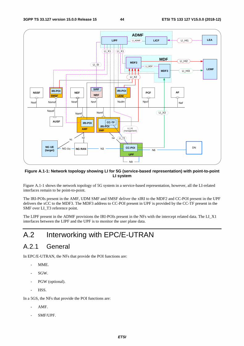
ETSI
ETSI TS 133 127 V15.0.0 (2018-12)443GPP TS 33.127 version 15.0.0 Release 15
NG UE(target)
NG-Uu N6NG RAN
AUSF
NSSF NEFSIRF IRI-POI
PCF AF
DN
N1N2 N4
Nssf Nnef Nnrf NpcfNudm Naf
NausfNamf Nsmf
LEMF
ADMFLIPF
MDF3
LI_X3
LI_HI1
LI_HI2
LI_HI3
LEA
UDMNRF
UPF
MDF2
N9
CC-POI
LI_X1
LI_X1(management)
N3
LI_MDF
LICFLI_ADMF
MDF
ADMF
IRI-POI
AMF SMF
CC-TF
IRI-POI
LI_T3
Nsmsf
SMSF
IRI-POI
LI_X2
LI_SI
LI_X1
Figure A.1-1: Network topology showing LI for 5G (service-based representation) with point-to-point LI system
Figure A.1-1 shows the network topology of 5G system in a service-based representation, however, all the LI-related interfaces remain to be point-to-point.
The IRI-POIs present in the AMF, UDM SMF and SMSF deliver the xIRI to the MDF2 and CC-POI present in the UPF delivers the xCC to the MDF3. The MDF3 address to CC-POI present in UPF is provided by the CC-TF present in the SMF over LI_T3 reference point.
The LIPF present in the ADMF provisions the IRI-POIs present in the NFs with the intercept related data. The LI_X1 interfaces between the LIPF and the UPF is to monitor the user plane data.
A.2 Interworking with EPC/E-UTRAN
A.2.1 General In EPC/E-UTRAN, the NFs that provide the POI functions are:
- MME.
- SGW.
- PGW (optional).
- HSS.
In a 5GS, the NFs that provide the POI functions are:
- AMF.
- SMF/UPF.
ETSI
ETSI TS 133 127 V15.0.0 (2018-12)453GPP TS 33.127 version 15.0.0 Release 15
- UDM.
- SMSF.
In an interworking scenario between the EPC and the 5GS, the AMF in 5GS and MME in EPC provide the IRI-POI functions for the related attach/registration related aspects. When the network topology includes SMF + PGW-C and UPF + PGW-U as the interworking NFs, it is recommended that these provide the POI functions for the PDU sessions as the target communication traffic coming from either of the two interworking networks pass through these NFs. In that case, the interception at the SGW and UPF (if present between the NG-RAN and the UPF + PGW-U) is not required unless the condition specified in NOTE 1 in clause A.2.1 applies.
In a non-roaming scenario, the IRI-POI present in the HSS + UDM also provide the LI functions. The IRI-POI present in the SMSF provides the LI functions for the SMS-related IRI events.
A.2.2 Topology view for a non-roaming scenario The overall network configuration for interworking between EPC-EUTRAN and 5GS in non-roaming scenario with the LI aspects is shown in figure A.2-1.
The 5G core system is shown using the service-based representation (as shown in TS 23.501 [2]) with the use of point-to-point LI system.
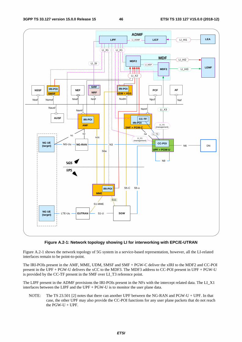
ETSI
ETSI TS 133 127 V15.0.0 (2018-12)463GPP TS 33.127 version 15.0.0 Release 15
NG UE(target)
NG-Uu N6NG-RAN
AUSF
NSSF NEFSIRF
IRI-POI PCF AF
DN
N1N2 N4
Nssf Nnef Nnrf NpcfNudm Naf
NausfNamf Nsmf
LEMFMDF3
LI_X3
LI_HI1
LI_HI2
LI_HI3
LI_SI
LEA
UDM + HSSNRF
UPF + PGW-U
MDF2
LI_X1(management)
N3
LI_MDF
LICFLI_ADMF
MDF
ADMF
IRI-POI
AMFSMF + PGW-C
CC-TF
IRI-POI
LI_T3
NG UE(target) LTE-Uu
S1-MME
S1-UEUTRAN
S11
SGW
MME
IRI-POI
ADMFLIPF
LI_X1
LI_X1(management)
CC-POI
N9
N26
S5-uS5-C
S6a
EPS
5GS
Nsmsf
SMSF
IRI-POI
LI_X2
LI_X1
Figure A.2-1: Network topology showing LI for interworking with EPC/E-UTRAN
Figure A.2-1 shows the network topology of 5G system in a service-based representation, however, all the LI-related interfaces remain to be point-to-point.
The IRI-POIs present in the AMF, MME, UDM, SMSF and SMF + PGW-C deliver the xIRI to the MDF2 and CC-POI present in the UPF + PGW-U delivers the xCC to the MDF3. The MDF3 address to CC-POI present in UPF + PGW-U is provided by the CC-TF present in the SMF over LI_T3 reference point.
The LIPF present in the ADMF provisions the IRI-POIs present in the NFs with the intercept related data. The LI_X1 interfaces between the LIPF and the UPF + PGW-U is to monitor the user plane data.
NOTE: The TS 23.501 [2] notes that there can another UPF between the NG-RAN and PGW-U + UPF. In that case, the other UPF may also provide the CC-POI functions for any user plane packets that do not reach the PGW-U + UPF.
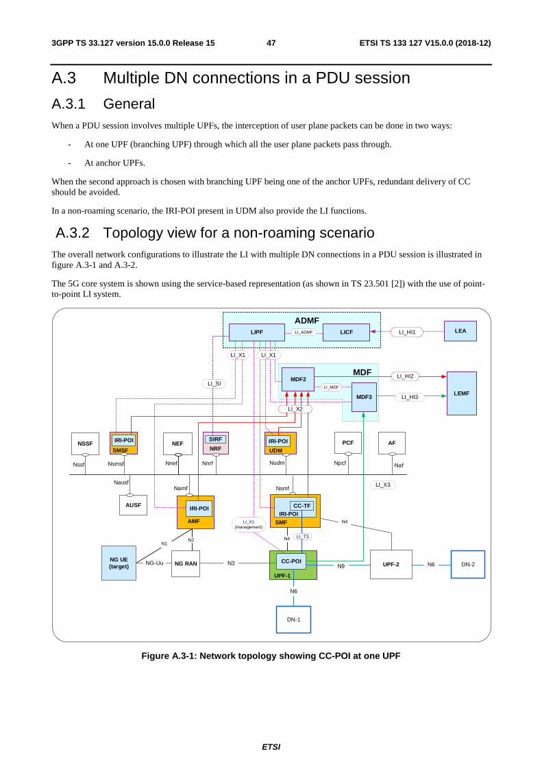
ETSI
ETSI TS 133 127 V15.0.0 (2018-12)473GPP TS 33.127 version 15.0.0 Release 15
A.3 Multiple DN connections in a PDU session
A.3.1 General When a PDU session involves multiple UPFs, the interception of user plane packets can be done in two ways:
- At one UPF (branching UPF) through which all the user plane packets pass through.
- At anchor UPFs.
When the second approach is chosen with branching UPF being one of the anchor UPFs, redundant delivery of CC should be avoided.
In a non-roaming scenario, the IRI-POI present in UDM also provide the LI functions.
A.3.2 Topology view for a non-roaming scenario The overall network configurations to illustrate the LI with multiple DN connections in a PDU session is illustrated in figure A.3-1 and A.3-2.
The 5G core system is shown using the service-based representation (as shown in TS 23.501 [2]) with the use of point-to-point LI system.
NG UE(target)
NG-Uu N9NG RAN
AUSF
NSSF NEFSIRF IRI-POI PCF AF
DN-1
N1N2
Nssf Nnef Nnrf NpcfNudm Naf
NausfNamf Nsmf
LEMF
ADMFLIPF
MDF3
LI_X3
LI_HI1
LI_HI2
LI_HI3
LI_SI
LEA
UDMNRF
UPF-1
MDF2
CC-POI
LI_X1(management)
N3
LI_MDF
LICFLI_ADMF
MDF
ADMF
IRI-POI
AMF SMF
CC-TFIRI-POI
LI_T3
UPF-2 DN-2N6
N4
N6
N4
LI_X1
SMSF
Nsmsf
LIPF
LI_X1
IRI-POI
LI_X2
Figure A.3-1: Network topology showing CC-POI at one UPF
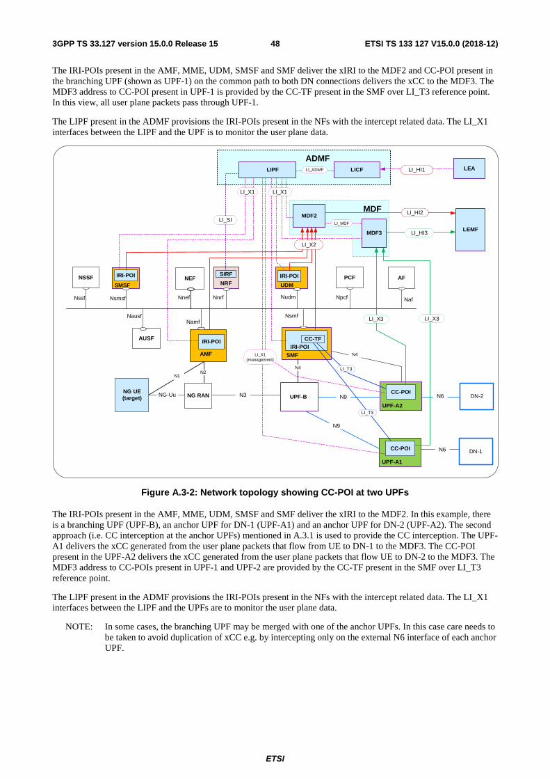
ETSI
ETSI TS 133 127 V15.0.0 (2018-12)483GPP TS 33.127 version 15.0.0 Release 15
The IRI-POIs present in the AMF, MME, UDM, SMSF and SMF deliver the xIRI to the MDF2 and CC-POI present in the branching UPF (shown as UPF-1) on the common path to both DN connections delivers the xCC to the MDF3. The MDF3 address to CC-POI present in UPF-1 is provided by the CC-TF present in the SMF over LI_T3 reference point. In this view, all user plane packets pass through UPF-1.
The LIPF present in the ADMF provisions the IRI-POIs present in the NFs with the intercept related data. The LI_X1 interfaces between the LIPF and the UPF is to monitor the user plane data.
N9
N6
N9NG UE(target)
NG-Uu NG RAN
AUSF
NSSF NEFSIRF IRI-POI PCF AF
DN-1
N1N2
Nssf Nnef Nnrf NpcfNudm Naf
NausfNamf
Nsmf
LEMF
ADMFLIPF
MDF3
LI_HI1
LI_HI2
LI_HI3
LI_SI
LEA
UDMNRF
UPF-B
MDF2
N3
LI_MDF
LICFLI_ADMF
MDF
ADMF
IRI-POI
AMF SMF
CC-TFIRI-POI
DN-2
N4
N4
LI_X1
UPF-A2
LI_T3
LI_X3
CC-POIN6
UPF-A1
LI_X1(management)
LI_T3
LI_X3
CC-POI
SMSF
Nsmsf
IRI-POI
LI_X1
LI_X2
Figure A.3-2: Network topology showing CC-POI at two UPFs
The IRI-POIs present in the AMF, MME, UDM, SMSF and SMF deliver the xIRI to the MDF2. In this example, there is a branching UPF (UPF-B), an anchor UPF for DN-1 (UPF-A1) and an anchor UPF for DN-2 (UPF-A2). The second approach (i.e. CC interception at the anchor UPFs) mentioned in A.3.1 is used to provide the CC interception. The UPF-A1 delivers the xCC generated from the user plane packets that flow from UE to DN-1 to the MDF3. The CC-POI present in the UPF-A2 delivers the xCC generated from the user plane packets that flow UE to DN-2 to the MDF3. The MDF3 address to CC-POIs present in UPF-1 and UPF-2 are provided by the CC-TF present in the SMF over LI_T3 reference point.
The LIPF present in the ADMF provisions the IRI-POIs present in the NFs with the intercept related data. The LI_X1 interfaces between the LIPF and the UPFs are to monitor the user plane data.
NOTE: In some cases, the branching UPF may be merged with one of the anchor UPFs. In this case care needs to be taken to avoid duplication of xCC e.g. by intercepting only on the external N6 interface of each anchor UPF.
ETSI
ETSI TS 133 127 V15.0.0 (2018-12)493GPP TS 33.127 version 15.0.0 Release 15
A.4 Non-3GPP access in a non-roaming scenario
A.4.1 General When the target UE is connected to the 5G core network via non-3GPP access, the POIs present in the following NFs of the PLMN where the N3IWF resides provide the LI functions:
- AMF.
- SMF.
- UPF.
- SMSF.
When the PLMN that has the N3IWF is the HPLMN, as illustrated in clause A.1, the IRI-POI present in the UDM also provide the LI functions.
When the PLMN that has N3IWF is different from the PLMN that provides the 3GPP access to the target UE, two different AMFs are involved in handling the target UE's registration accepts (this is not illustrated in this clause). In this case, depending on the operator policy, the SMSF present in either of the two networks may perform the routing of SMS messages to and from the target UE.
The PLMN that provides the 3GPP access can be a VPLMN and PLMN where the N3IWF resides can be the HPLMN. In this case, the AMF in the HPLMN provides the IRI-POI functions for non-3GPP access related registration events when the target UE is roaming. The SMSF present in the HPLMN may have to provide the IRI-POI functions for the SMS related messages routed via non-3GPP access network.
A.4.2 Topology view The overall network configuration for non-3GPP access in a non-roaming scenario with the LI aspects is shown in figure A.4-1. In this view, the target UE is not connected to a 3GPP access network.
The 5G core system is shown using the service-based representation (as shown in TS 23.501 [2]) with the use of point-to-point LI system.
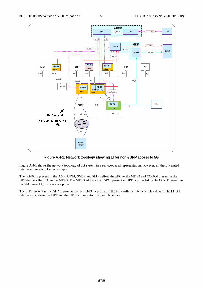
ETSI
ETSI TS 133 127 V15.0.0 (2018-12)503GPP TS 33.127 version 15.0.0 Release 15
NG UE(target)
N6
AUSF
NSSF NEFSIRF IRI-POI
PCF AF
DN
N2 N4
Nssf Nnef Nnrf NpcfNudm Naf
NausfNamf Nsmf
LEMF
ADMFLIPF
MDF3
LI_X3
LI_HI1
LI_HI2
LI_HI3
LI_SI
LEA
UDMNRF
UPF
MDF2
N9
CC-POI
LI_X1
LI_X1(management)
N3
LI_MDF
LICFLI_ADMF
MDF
ADMF
IRI-POI
AMF SMF
CC-TF
IRI-POI
LI_T3
Y1
Y2
N3IWF
Untrusted
non-3GPP
access
N1 Nwu
Non-3GPP access network
3GPP Network
Nsmsf
SMSF
LIPF
LI_X1
IRI-POI
LI_X2
Figure A.4-1: Network topology showing LI for non-3GPP access to 5G
Figure A.4-1 shows the network topology of 5G system in a service-based representation, however, all the LI-related interfaces remain to be point-to-point.
The IRI-POIs present in the AMF, UDM, SMSF and SMF deliver the xIRI to the MDF2 and CC-POI present in the UPF delivers the xCC to the MDF3. The MDF3 address to CC-POI present in UPF is provided by the CC-TF present in the SMF over LI_T3 reference point.
The LIPF present in the ADMF provisions the IRI-POIs present in the NFs with the intercept related data. The LI_X1 interfaces between the LIPF and the UPF is to monitor the user plane data.

ETSI
ETSI TS 133 127 V15.0.0 (2018-12)513GPP TS 33.127 version 15.0.0 Release 15
Annex Z (informative): Change history
Change history Date Meeting TDoc CR Rev Cat Subject/Comment New
version 2018-12 SA#82 SP-180991 Release 15 draft Approved at TSG SA#82 15.0.0
ETSI
ETSI TS 133 127 V15.0.0 (2018-12)523GPP TS 33.127 version 15.0.0 Release 15
History
Document history
V15.0.0 December 2018 Publication