Embed Size (px)
Citation preview
1
G E Z EPuSL+SL-FR_E_xx0899.p65 Planungsunterlage Slimdrive SL mit SL-FR Englisch
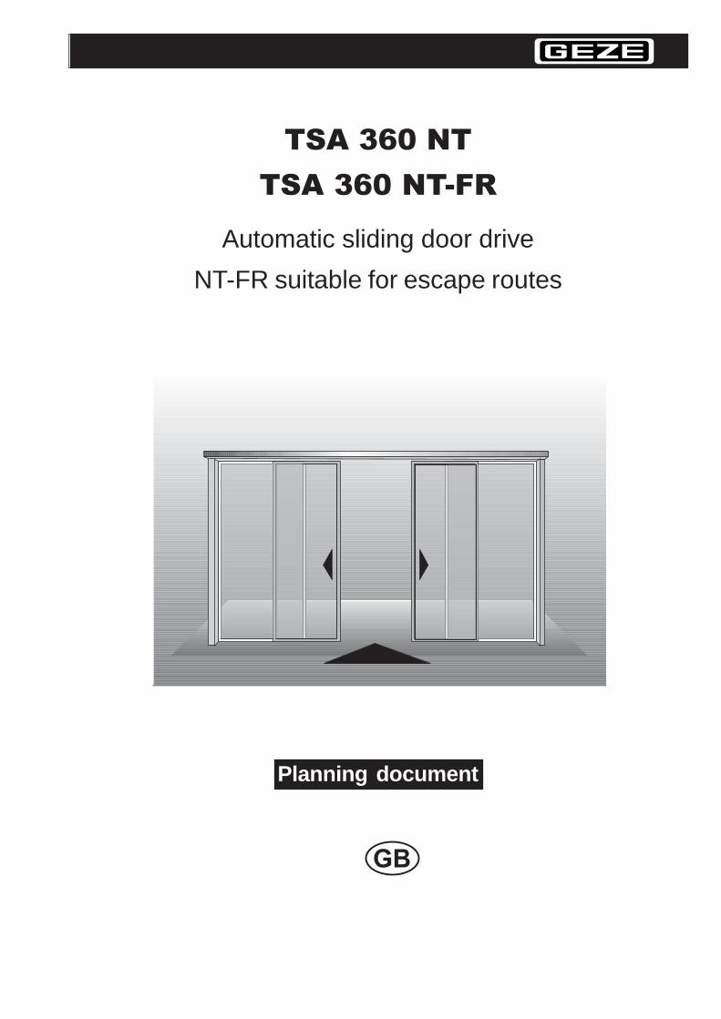
TSA 360 NT
TSA 360 NT-FR
Automatic sliding door drive
NT-FR suitable for escape routes
Planning document
2
PuSL+SL-FR_E_xx0899.p65 Planungsunterlage Slimdrive Sl mit SL-FR englisch
Contents
Areas of application 3
Product features 4
System description 5
Safety functions 10
Installation variations 11
Horizontal and vertical cross sections 15ISO-profile system for facade constructions 15ISO profile system with side panels- wall mounting 16ISO-profile system, self-supporting between panels 17Framed casement to profile system A 18Framed casement to profile system B 19Timber-framed casement to wall 20
Calculation of the overall length of the complete system 21
Calculation of glass dimensions for sliding leaf 21
Function description 22
Control elements / actuation devices 24
Draught lobbies 25
Wiring diagram TSA 360 NT, NT-FR 26
Approvals 27
3
G E Z EPuSL+SL-FR_E_xx0899.p65 Planungsunterlage Slimdrive SL mit SL-FR Englisch
Areas of applicationGEZE sliding door systems are used as automatic doors with horizontally sliding door leaves in lowand high usage areas.
TSA 360 NT: The aesthetically designed sliding door system, single- or double-leaf
TSA 360 NT-FR: Developed especially for installation on escape and rescue routes wheresafety is of paramount importance.
Office buildings
Public buildings
Chemists’ premises
Banks
Hotels and restaurants
Administration buildings
Hospitals
Care homes for the elderly or disabled
Airports and railway stations
Car show rooms
Industrial buildings
Draught lobbies
Extensive mounting options are available owing to the robust construction of the drive.
4
PuSL+SL-FR_E_xx0899.p65 Planungsunterlage Slimdrive Sl mit SL-FR englisch
Product featuresTSA 360 NT or NT-FR: for architects, planners, clients and operators
Allows largest possible headroomHigh-quality materials and the latest in control technology ensure high performance inyour designated area of application
Suitable for different types of fittings due to a variety of adjustment options
TSA 360 NT or NT-FR: for fabricators and partners
Small number of profiles and modular construction
allows fast production of all customer-specific opening widths
reduces the storage costs
allows pre-assembly of the mechanic drive components
reduces installation times on site
TSA 360 NT-FR: for use on escape and rescue routes
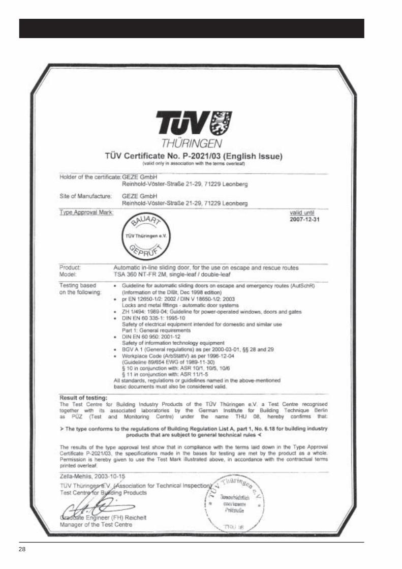
Dual-motor technology with maintenance-free motorsThe TSA 360 NT-FR has been approved for use on escape and rescue routes inaccordance with the guidelines for automatic sliding doors in escape routes(AutSchR)In addition to this, the sliding door drive has been tested in accordance withprEN 12650-1/2 and DIN V 18650-1/2 (2003).
5
G E Z EPuSL+SL-FR_E_xx0899.p65 Planungsunterlage Slimdrive SL mit SL-FR Englisch
System description
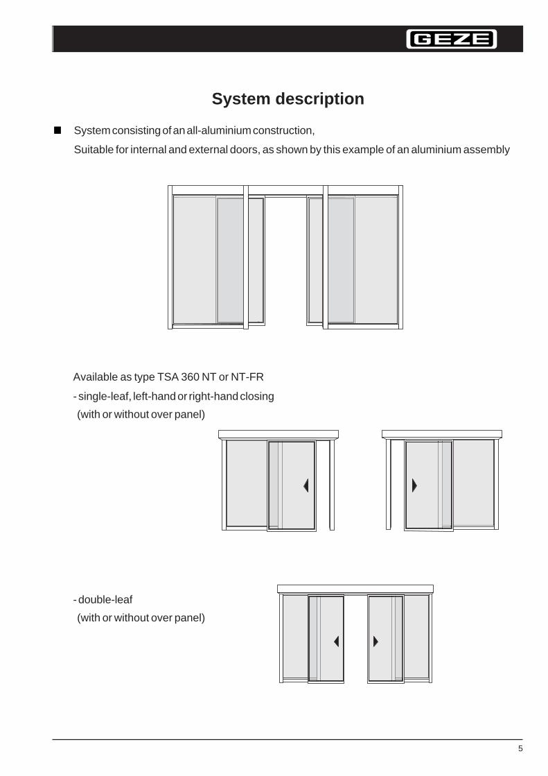
System consisting of an all-aluminium construction,
Suitable for internal and external doors, as shown by this example of an aluminium assembly
- double-leaf
(with or without over panel)
Available as type TSA 360 NT or NT-FR
- single-leaf, left-hand or right-hand closing
(with or without over panel)
6
PuSL+SL-FR_E_xx0899.p65 Planungsunterlage Slimdrive Sl mit SL-FR englisch
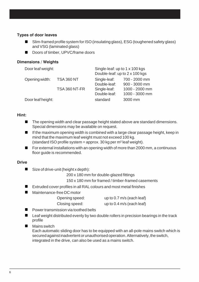
Types of door leaves
Slim-framed profile system for ISO (insulating glass), ESG (toughened safety glass)and VSG (laminated glass)
Doors of timber, UPVC/frame doors
Dimensions / Weights
Door leaf weight: Single-leaf: up to 1 x 100 kgsDouble-leaf: up to 2 x 100 kgs
Opening width: TSA 360 NT Single-leaf: 700 - 2000 mmDouble-leaf: 900 - 3000 mm
TSA 360 NT-FR Single-leaf: 1000 - 2000 mmDouble-leaf: 1000 - 3000 mm
Door leaf height: standard 3000 mm
Hint:
The opening width and clear passage height stated above are standard dimensions.Special dimensions may be available on request.
If the maximum opening width is combined with a large clear passage height, keep inmind that the maximum leaf weight must not exceed 100 kg.(standard ISO profile system = approx. 30 kg per m² leaf weight).
For external installations with an opening width of more than 2000 mm, a continuousfloor guide is recommended.
Drive
Size of drive-unit (height x depth):200 x 180 mm for double-glazed fittings150 x 180 mm for framed / timber-framed casements
Extruded cover profiles in all RAL colours and most metal finishesMaintenance-free DC motor
Opening speed: up to 0.7 m/s (each leaf)Closing speed: up to 0.4 m/s (each leaf)
Power transmission via toothed beltsLeaf weight distributed evenly by two double rollers in precision bearings in the trackprofile
Mains switchEach automatic sliding door has to be equipped with an all-pole mains switch which issecured against inadvertent or unauthorised operation. Alternatively, the switch,integrated in the drive, can also be used as a mains switch.
7
G E Z EPuSL+SL-FR_E_xx0899.p65 Planungsunterlage Slimdrive SL mit SL-FR Englisch
Only type NT-FR:
Duplicate processing system by means of dual-motor technology/accumulator inconnection with a redundant control
Lockable programme switchThe programme switch may only be operated by authorized persons. For that reasona key-operated switch is absolutely necessary. The operating mode selected mustbe clearly identifiable.
Self-monitoring movement detector (redundant).The functionality must be controlled constantly. If an error is indicated the door movesinto the open position (repair required).
Information for the locking of emergency exit doors (mode of operation “NIGHT“):Automatic sliding doors for use on escape routes may be locked, if the doors are notrequired as emergency exit doors for this specific period of time. This is normally thecase if there are no more people in the building or if another escape route isindicated.
8
PuSL+SL-FR_E_xx0899.p65 Planungsunterlage Slimdrive Sl mit SL-FR englisch
Control
Fully digital control via 16 Bit high-performance microprocessor
All adjustments of the system as well as the indication of the function, fault andmaintenance parameters via programme switch
Modes of operation: automatic, permanently open, shop-closing time (one-way), night
The reduced opening width (winter opening) is infinitely variable in the self-learning mode;for the version TSA 360 NT-FR the prescribed minimum escape width (min. 30%) must betaken into consideration
Different hold-open times for summer operation, winter operation and key-operatedoperation
Display of statistical data via programme switch(number of opening movements, service interval)
Self-learning door control
Hold-open time can be automatically adapted to access frequency
Connection to fire alarm system
Electromechanical locking with optional alarm contact for alarm systems
Opening and closing speeds are individually adjustable
Two safety photoelectric barriersIf one of the safety photoelectric barrier fails, the door moves into the OPEN position andremains open in this position until repaired.
Error indication of safety sensors
Error indication radar movement detector
Technical features
Mains connection: 230 VAC; +6%/-10%; 50/60 Hz
Power consumption max. 300 VA
Actuation elements
Only type-tested movement detectors must be connected in escape direction, apart fromthat, all actuation elements can be connected, e.g.:
Radar movement detector, where detection is independent of temperatureInfrared motion detectorsLight curtain
Buttons/switches
Key-operated switch
Code card reader
9
G E Z EPuSL+SL-FR_E_xx0899.p65 Planungsunterlage Slimdrive SL mit SL-FR Englisch
Options
For version TSA 360 NT and NT-FR
Connection to fire alarm system
permanently potential-free contact, door opens from any mode of operation and staysopen
Link to burglar alarm
door monitored via external reed switch as well as micro-switch on the locking deviceChemists' late night opening setting
Tamper contact for external key-operated switch
Fault warning
Standard locking
Floor spring at bottom door shoe
For version TSA 360 NT (not permitted for NT-FR)
Draught lobby or interlocking function can be controlled with only 1 programme switch for 2installations
Fixed panel safeguarding via sensors
Emergency locking
Switching over to other modes of operation by means of timer
HINT:conditioned switch-over for FR system(only between the modes: shop closing time, automatic and permanently open)
10
PuSL+SL-FR_E_xx0899.p65 Planungsunterlage Slimdrive Sl mit SL-FR englisch
Safety functionsClosing force limited to <150 N
Opening force limited to <150 N
Safety sensor with self-testing function (safety photoelectric barrier or light curtain)
Automatic reversing function with adjustable reversing pressure. The door opensautomatically, if it meets an obstacle during closure (adjustable reversing pressure)
Anti-Lock in opening direction
Manual emergency unlocking (standard) with unlocking pin at the drive,electric emergency unlocking (option)
Battery pack to open and close the door in the case of power failure (no permanentoperation)
Integrated mains switch
For variant TSA 360 NT-FR the following will apply in addition:
Automatic opening of the door from the mode of operation “AUT“ and “Shop Closing“ inthe case of failure or emergency owing to a dual-motor technology in connection with abattery pack.
11
G E Z EPuSL+SL-FR_E_xx0899.p65 Planungsunterlage Slimdrive SL mit SL-FR Englisch
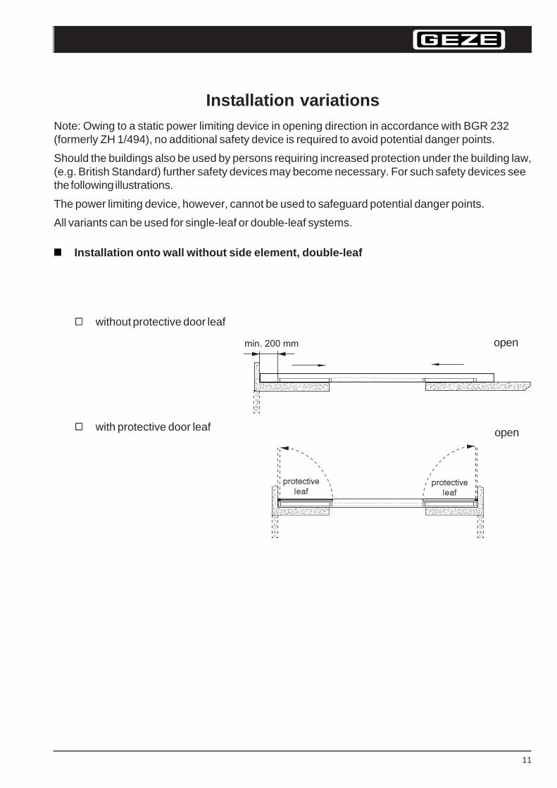
Installation variationsNote: Owing to a static power limiting device in opening direction in accordance with BGR 232(formerly ZH 1/494), no additional safety device is required to avoid potential danger points.
Should the buildings also be used by persons requiring increased protection under the building law,(e.g. British Standard) further safety devices may become necessary. For such safety devices seethe following illustrations.
The power limiting device, however, cannot be used to safeguard potential danger points.
All variants can be used for single-leaf or double-leaf systems.
Installation onto wall without side element, double-leaf
without protective door leaf
with protective door leaf
protective
leafprotective
leaf
open
open
12
PuSL+SL-FR_E_xx0899.p65 Planungsunterlage Slimdrive Sl mit SL-FR englisch
max. 3000 mm
max. 3000 mm
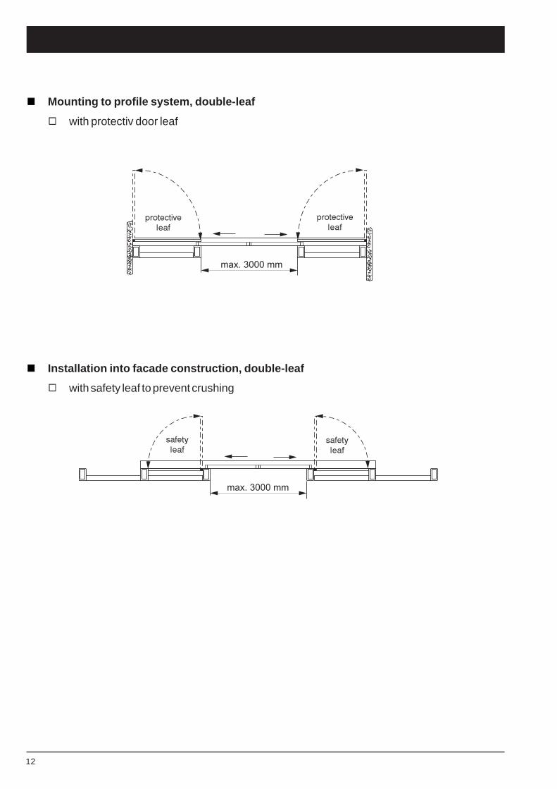
Mounting to profile system, double-leaf
with protectiv door leaf
Installation into facade construction, double-leaf
with safety leaf to prevent crushing
protective
leaf
protective
leaf
safety
leaf
safety
leaf
13
G E Z EPuSL+SL-FR_E_xx0899.p65 Planungsunterlage Slimdrive SL mit SL-FR Englisch
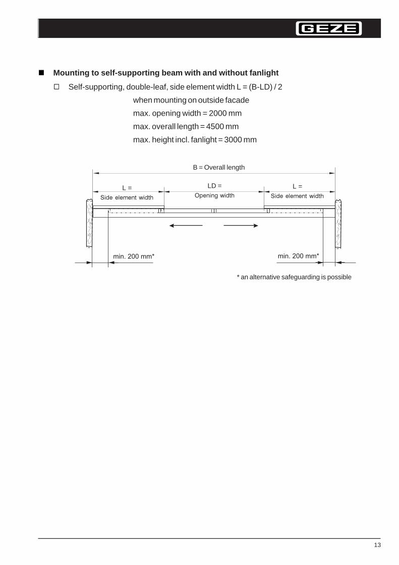
Mounting to self-supporting beam with and without fanlight
Self-supporting, double-leaf, side element width L = (B-LD) / 2
when mounting on outside facade
max. opening width = 2000 mm
max. overall length = 4500 mm
max. height incl. fanlight = 3000 mm
B = Overall length
LD =Opening width
L =Side element width
L =Side element width
* an alternative safeguarding is possible
14
PuSL+SL-FR_E_xx0899.p65 Planungsunterlage Slimdrive Sl mit SL-FR englisch
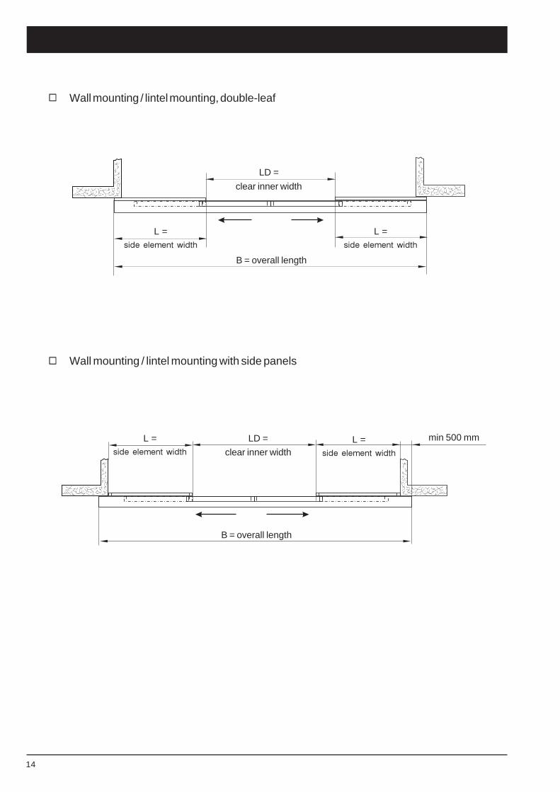
Wall mounting / lintel mounting with side panels
Wall mounting / lintel mounting, double-leaf
B = overall length
LD =
clear inner width
L =side element width
B = overall length
LD =
clear inner widthL =
side element width
min 500 mm
L =side element width
L =side element width
15
G E Z EPuSL+SL-FR_E_xx0899.p65 Planungsunterlage Slimdrive SL mit SL-FR Englisch
2
Variant 2
Variant 1standard
Light barrier
Variant 3
Providedby customer
Sub-structure tobe provided by customer
OK FF
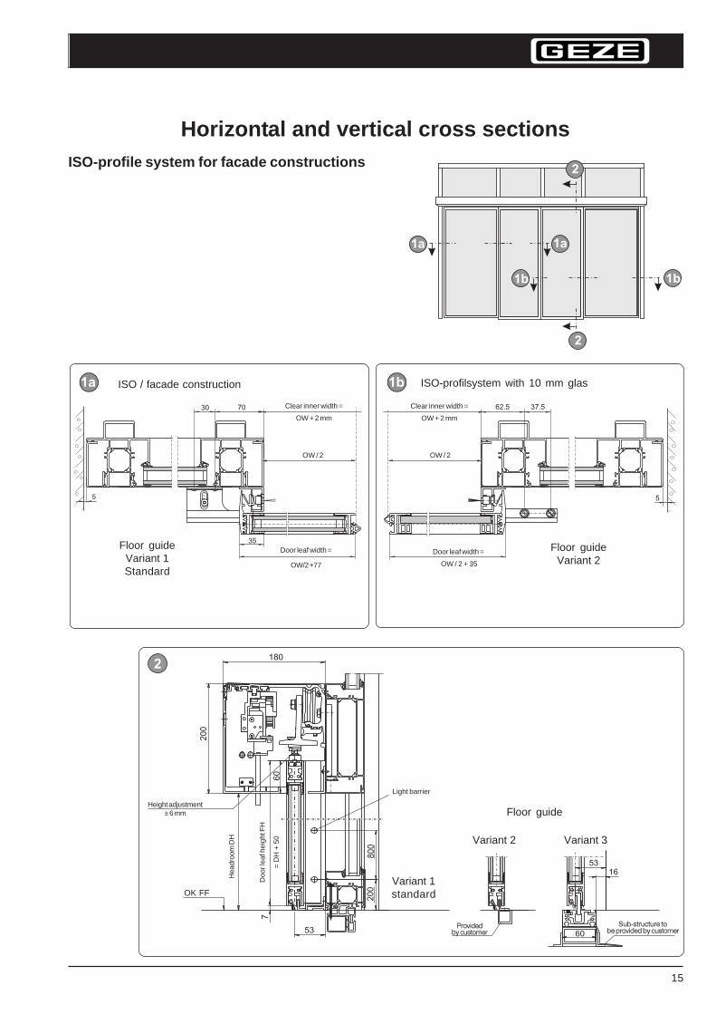
ISO / facade construction ISO-profilsystem with 10 mm glas
Clear inner width =
OW + 2 mm
Floor guideVariant 1Standard
Floor guideVariant 2
Door leaf width =
OW/2 +77
Doo
r lea
f hei
ght F
H
= D
H +
50
Hea
droo
m D
H
OW / 2 OW / 2
Door leaf width =
OW / 2 + 35
Floor guide
Clear inner width =
OW + 2 mm
Height adjustment± 6 mm
Horizontal and vertical cross sectionsISO-profile system for facade constructions
16
PuSL+SL-FR_E_xx0899.p65 Planungsunterlage Slimdrive Sl mit SL-FR englisch
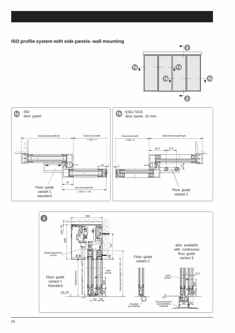
ISO profile system with side panels- wall mounting
2
Floor guidevariant 2
Floor guidevariant 1Standard
Lightbarrier
Height adjustment± 6 mm
OK FF
Doo
r lea
f hei
ght F
H =
DH
+ 5
0
Hea
droo
m D
H
Sid
e el
emen
t hig
ht F
H =
DH
+ 4
7
Clear inner width
= OW + 2
Side element width left Side element width right
Floor guidevariant 1standard
Floor guidevariant 2
door leaf width FB
= OW / 2 + 40
ISOdoor panel
ESG / VGSdoor panel, 10 mm
Lightbarrier
also availablewith continuous
floor guidevariant 3
Clear inner width
= OW + 2
Sub-structure tobe provided by
customerProvided
by customer
17
G E Z EPuSL+SL-FR_E_xx0899.p65 Planungsunterlage Slimdrive SL mit SL-FR Englisch
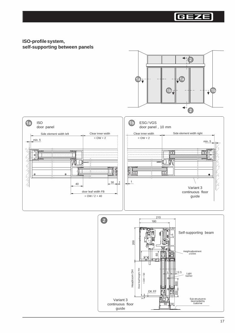
ISO-profile system,self-supporting between panels
2
Variant 3continuous floor
guide
Height adjustment± 6 mm
OK FF
Hea
droo
m D
H
Doo
r lea
f hei
ght
FH
= D
H +
50
Self-supporting beam
ISOdoor panel
ESG / VGSdoor panel , 10 mm
Variant 3continuous floor
guide
Side element width left Clear inner width
= OW + 2
door leaf width FB
= OW / 2 + 40
Clear inner width
= OW + 2
Side element width right
Lightbarrier
Sub-structure tobe provided by
customer
18
PuSL+SL-FR_E_xx0899.p65 Planungsunterlage Slimdrive Sl mit SL-FR englisch
10
7
80
02
00
15
0
180
85
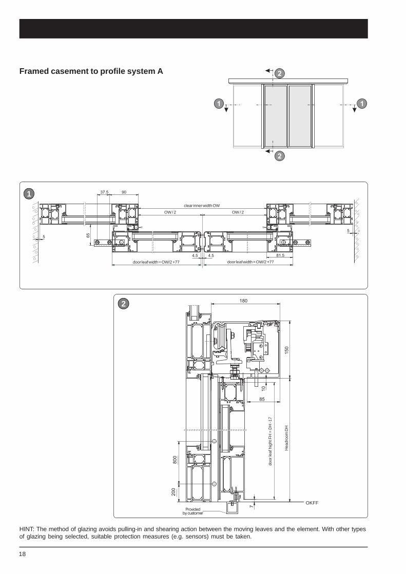
HINT: The method of glazing avoids pulling-in and shearing action between the moving leaves and the element. With other typesof glazing being selected, suitable protection measures (e.g. sensors) must be taken.
Framed casement to profile system A
door
leaf
hig
ht F
H =
DH
-17
Hea
droo
m D
H
Providedby customer
clear inner width OW
OW / 2 OW / 2
door leaf width = OW/2 +77 door leaf width = OW/2 +77
2
1
OKFF
19
G E Z EPuSL+SL-FR_E_xx0899.p65 Planungsunterlage Slimdrive SL mit SL-FR Englisch
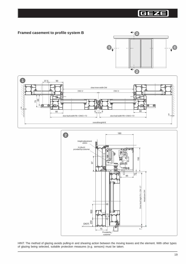
Framed casement to profile system B
door leaf width FB = OW/2 +72
overall lenghth B
OW / 2 OW / 2
door leaf width FB = OW/2 +72
2
1
Height adjustment ±6mm
OKFF
Provided bycustomer
Doo
r lea
f hig
ht F
H =
DH
-17
Hea
droo
m D
HFL 85x10
provided by customer
clear inner width OW
HINT: The method of glazing avoids pulling-in and shearing action between the moving leaves and the element. With other typesof glazing being selected, suitable protection measures (e.g. sensors) must be taken.
20
PuSL+SL-FR_E_xx0899.p65 Planungsunterlage Slimdrive Sl mit SL-FR englisch
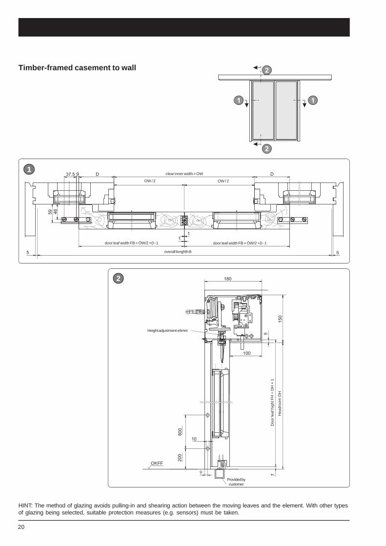
Timber-framed casement to wall
Height adjustment ±6mm
2
1
Doo
r lea
f hig
ht F
H =
DH
+ 1
Hea
droo
m D
H
OKFF
door leaf width FB = ÖW/2 +D -1
clear inner width = OW
OW / 2 OW / 2
overall lenghth B
door leaf width FB = ÖW/2 +D -1
Provided bycustomer
HINT: The method of glazing avoids pulling-in and shearing action between the moving leaves and the element. With other typesof glazing being selected, suitable protection measures (e.g. sensors) must be taken.
21
G E Z EPuSL+SL-FR_E_xx0899.p65 Planungsunterlage Slimdrive SL mit SL-FR Englisch
B
*)
TN063AST RF-TN063AST
fael-elbuod0003-008WÖ
001+WOx2=B
0003-0001WÖ
001+WOx2=B
fael-elgnis0002-007WÖ
56+WOx2=B
0002-0001WÖ
56+WOx2=B
ÖW
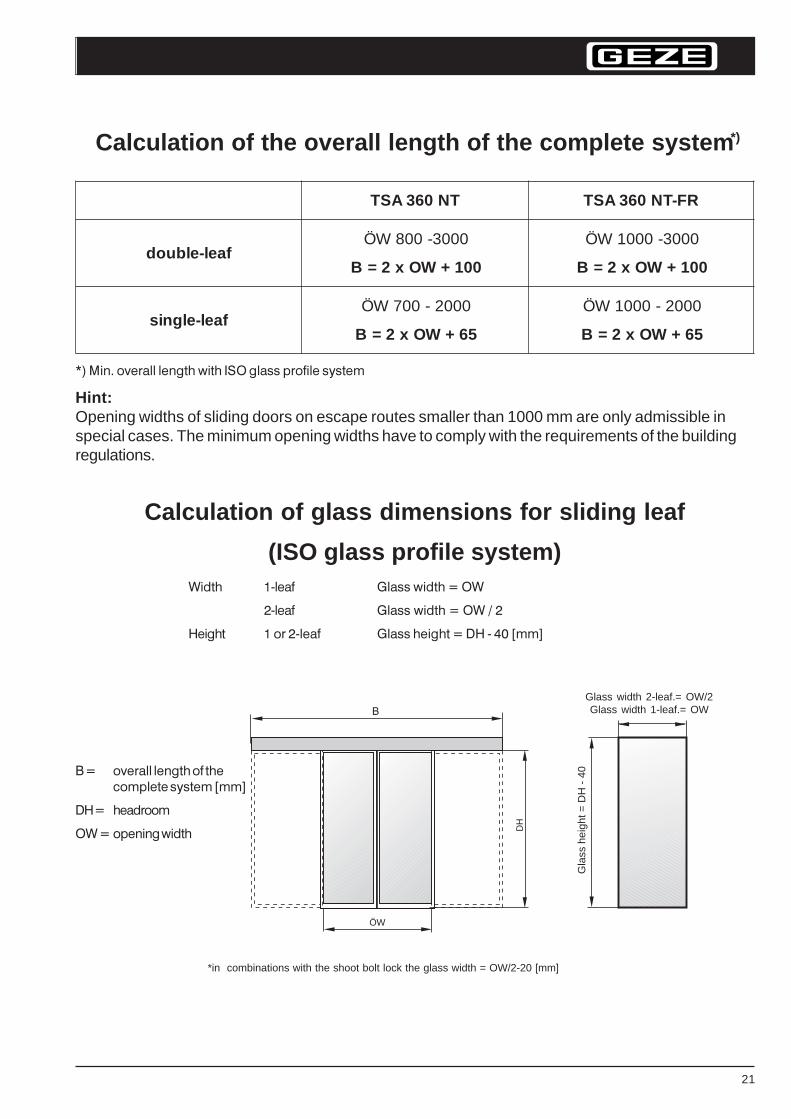
Calculation of the overall length of the complete system
*) Min. overall length with ISO glass profile system
Hint:Opening widths of sliding doors on escape routes smaller than 1000 mm are only admissible inspecial cases. The minimum opening widths have to comply with the requirements of the buildingregulations.
Calculation of glass dimensions for sliding leaf
(ISO glass profile system)Width 1-leaf Glass width = OW
2-leaf Glass width = OW / 2
Height 1 or 2-leaf Glass height = DH - 40 [mm]
*in combinations with the shoot bolt lock the glass width = OW/2-20 [mm]
B = overall length of thecomplete system [mm]
DH = headroom
OW = opening width
Gla
ss h
eigh
t = D
H -
40
Glass width 2-leaf.= OW/2Glass width 1-leaf.= OW
22
PuSL+SL-FR_E_xx0899.p65 Planungsunterlage Slimdrive Sl mit SL-FR englisch
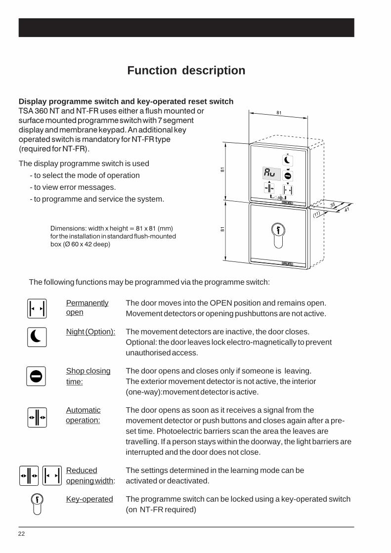
Display programme switch and key-operated reset switchTSA 360 NT and NT-FR uses either a flush mounted or
surface mounted programme switch with 7 segment
display and membrane keypad. An additional key
operated switch is mandatory for NT-FR type
(required for NT-FR).
The display programme switch is used
- to select the mode of operation
- to view error messages.
- to programme and service the system.
The following functions may be programmed via the programme switch:
Permanently The door moves into the OPEN position and remains open.Movement detectors or opening pushbuttons are not active.
Night (Option): The movement detectors are inactive, the door closes.Optional: the door leaves lock electro-magnetically to preventunauthorised access.
Shop closing The door opens and closes only if someone is leaving.The exterior movement detector is not active, the interior(one-way):movement detector is active.
Automatic The door opens as soon as it receives a signal from themovement detector or push buttons and closes again after a pre-set time. Photoelectric barriers scan the area the leaves aretravelling. If a person stays within the doorway, the light barriers areinterrupted and the door does not close.
Reduced The settings determined in the learning mode can beopening width: activated or deactivated.
Key-operated The programme switch can be locked using a key-operated switch(on NT-FR required)
Function description
Dimensions: width x height = 81 x 81 (mm)for the installation in standard flush-mountedbox (Ø 60 x 42 deep)
open
time:
operation:
23
G E Z EPuSL+SL-FR_E_xx0899.p65 Planungsunterlage Slimdrive SL mit SL-FR Englisch
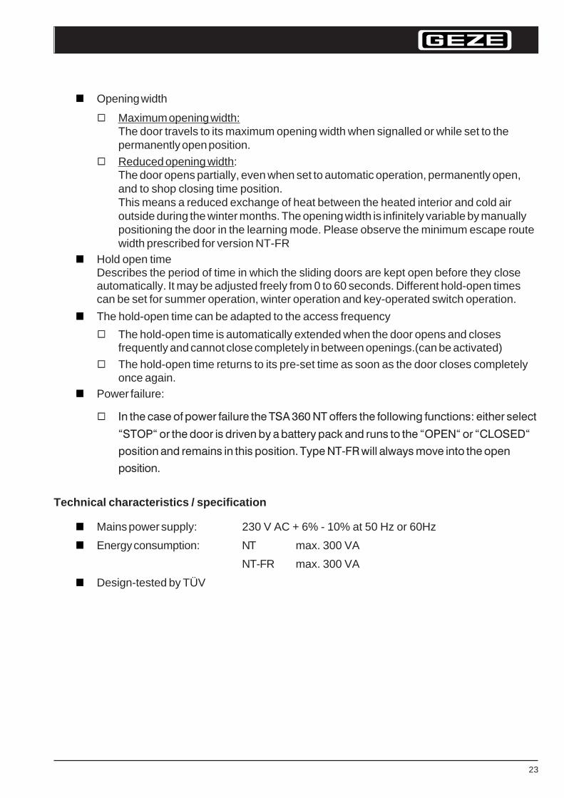
Opening width
Maximum opening width:The door travels to its maximum opening width when signalled or while set to thepermanently open position.
Reduced opening width:The door opens partially, even when set to automatic operation, permanently open,and to shop closing time position.This means a reduced exchange of heat between the heated interior and cold airoutside during the winter months. The opening width is infinitely variable by manuallypositioning the door in the learning mode. Please observe the minimum escape routewidth prescribed for version NT-FR
Hold open timeDescribes the period of time in which the sliding doors are kept open before they closeautomatically. It may be adjusted freely from 0 to 60 seconds. Different hold-open timescan be set for summer operation, winter operation and key-operated switch operation.
The hold-open time can be adapted to the access frequency
The hold-open time is automatically extended when the door opens and closesfrequently and cannot close completely in between openings.(can be activated)
The hold-open time returns to its pre-set time as soon as the door closes completelyonce again.
Power failure:
In the case of power failure the TSA 360 NT offers the following functions: either select
“STOP“ or the door is driven by a battery pack and runs to the “OPEN“ or “CLOSED“
position and remains in this position. Type NT-FR will always move into the open
position.
Technical characteristics / specification
Mains power supply: 230 V AC + 6% - 10% at 50 Hz or 60Hz
Energy consumption: NT max. 300 VA
NT-FR max. 300 VA
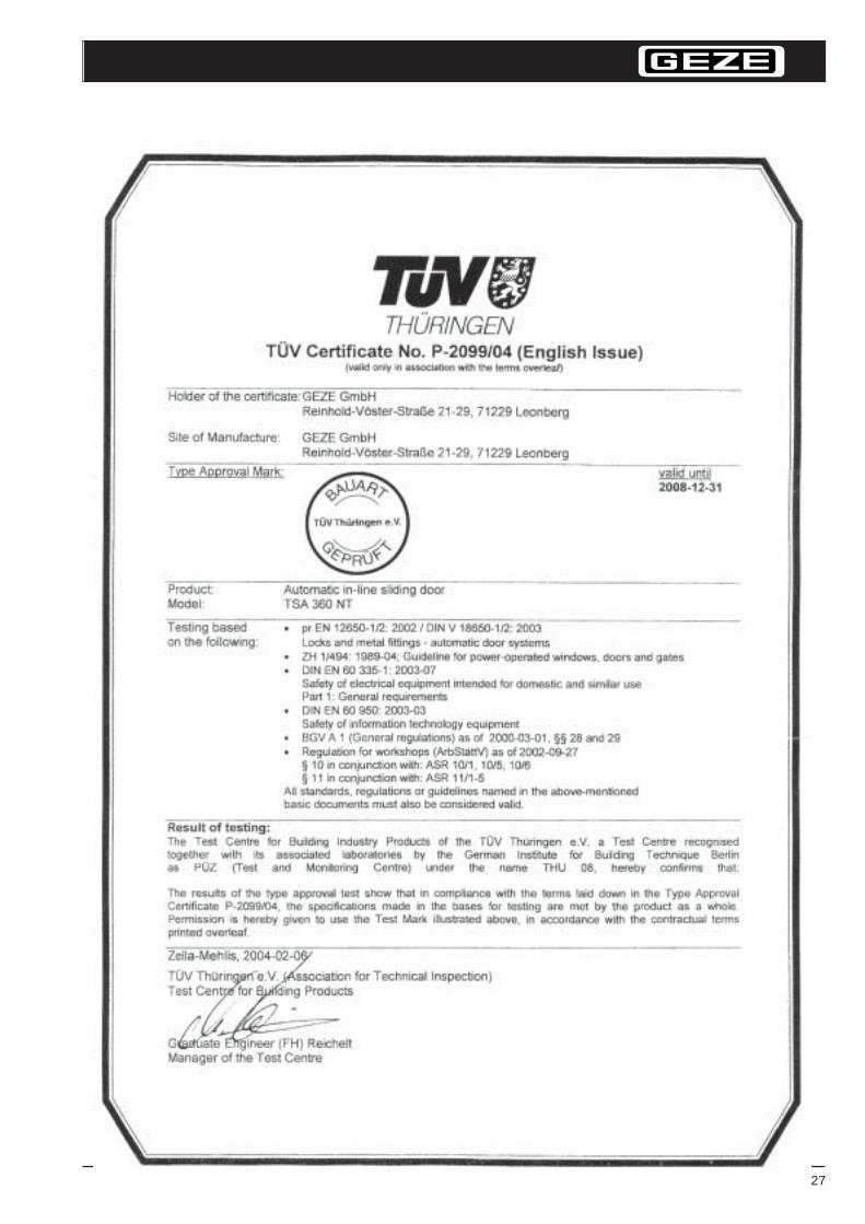
Design-tested by TÜV
24
PuSL+SL-FR_E_xx0899.p65 Planungsunterlage Slimdrive Sl mit SL-FR englisch
Control elements / actuation devicesOnly approved radar movement detectors are permitted in the direction of the emergency exit.
Radar movement detectors are activated by any kind of movement within the detectionzone. The movement causes a delayed reflection of the beam transmitted by the radarunit. This shifted echo is measured, analysed and passed on in the form of an openingsignal.
Active infra-red movement detector are activated by people and objects based on theprinciple of short wave infra-red reflection. This provides a very precisely adjustabledetection zone. It only analyses light transmitted by itself which means a very low level ofinterference. The opening signal is not only triggered by people and animals, but also byshopping trollies, hospital beds etc.
Passive infra-red movement detectors are activated by changes in temperature inconjunction with movement which makes them suitable for recognising people. Ashopping trolley would not be detected due to the lack of heat emission.
Switch, key-operated switch, etc.
Remote controls
Please notice:Radar or infra-red movement detectors have to be protected from rain, snow and sun bye.g. a customer provided roof.
Locking the door, leaving / entering the building
How to pass the locked door?
The programme switch is set to night-setting. The door is closed and locked mechanically.
Leaving the room:Operating the manual unlocking device opens the door. It will close and lock automaticallyafter you have left the room.
Entering the room:The door may be opened with a key-operated switch or any other electronic actuationdevice. The door is unlocked and opens.After you have left the room, the door closes and locks automatically.Now you can select the desired operation mode using the programme switch.
25
G E Z EPuSL+SL-FR_E_xx0899.p65 Planungsunterlage Slimdrive SL mit SL-FR Englisch
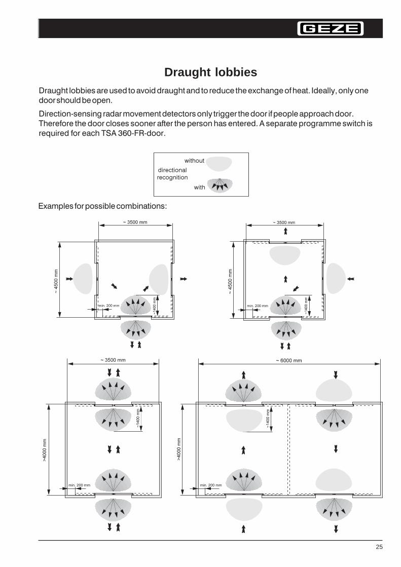
Draught lobbiesDraught lobbies are used to avoid draught and to reduce the exchange of heat. Ideally, only one
door should be open.
Direction-sensing radar movement detectors only trigger the door if people approach door.
Therefore the door closes sooner after the person has entered. A separate programme switch is
required for each TSA 360-FR-door.
Examples for possible combinations:
directional
recognition
with
without
26
PuSL+SL-FR_E_xx0899.p65 Planungsunterlage Slimdrive Sl mit SL-FR englisch
3)1)
Y 2
22
22
3
2
11
1
22
22
SE
S E
Y Y
Y YY Y
100cm
20cm
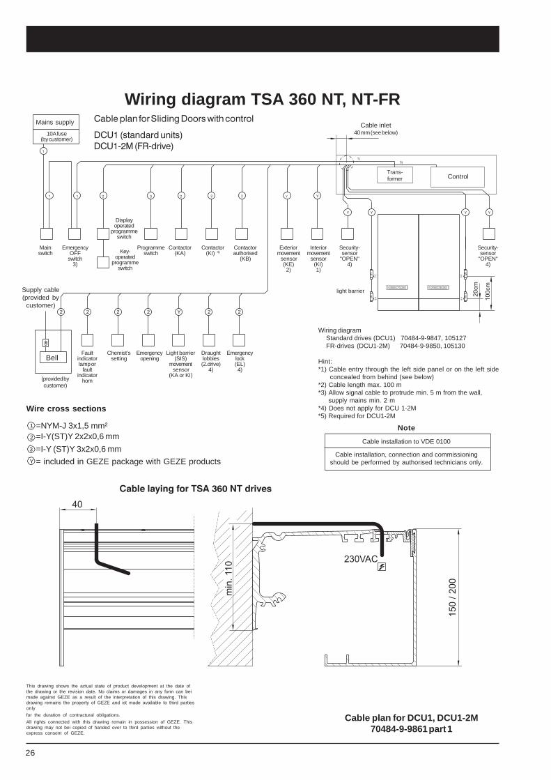
Cable plan for Sliding Doors with control
DCU1 (standard units)DCU1-2M (FR-drive)
40
230VAC
min
.11
0
15
0/
20
0
Wiring diagram TSA 360 NT, NT-FRMains supply
10A fuse(by customer)
EmergencyOFF
switch3)
Programmeswitch
Cable inlet40 mm (see below)
Control
Mainswitch
Displayoperated
programmeswitch
Contactor(KA)
Chemist’ssetting
Interiormovement
sensor(KI)1)
Exteriormovement sensor
(KE)2)
Faultindicatorlamp or
faultindicator
horn
Supply cable(provided by
customer)
Bell
Cable plan for DCU1, DCU1-2M70484-9-9861 part 1
Wire cross sections
1 =NYM-J 3x1,5 mm²2 =I-Y(ST)Y 2x2x0,6 mm
3 =I-Y (ST)Y 3x2x0,6 mmY = included in GEZE package with GEZE products
Wiring diagramStandard drives (DCU1) 70484-9-9847, 105127FR-drives (DCU1-2M) 70484-9-9850, 105130
Hint:*1) Cable entry through the left side panel or on the left side
concealed from behind (see below)*2) Cable length max. 100 m*3) Allow signal cable to protrude min. 5 m from the wall,
supply mains min. 2 m*4) Does not apply for DCU 1-2M*5) Required for DCU1-2M
Contactor(KI) 4)
Contactorauthorised
(KB)
(provided bycustomer)
Emergencyopening
Light barrier(SIS)
movement sensor
(KA or KI)
Draughtlobbies(2.drive)
4)
Emergencylock(EL)4)
Trans-former
light barrier
Key-operated
programmeswitch
Security-sensor
"OPEN"4)
Security-sensor
"OPEN"4)
This drawing shows the actual state of product development at the date ofthe drawing or the revision date. No claims or damages in any form can beimade against GEZE as a result of the interpretation of this drawing. Thisdrawing remains the property of GEZE and ist made available to third partiesonly
for the duration of contractural obligations.
All rights connected with this drawing remain in possession of GEZE. Thisdrawing may not bei copied of handed over to third parties without theexpress consent of GEZE.
Cable laying for TSA 360 NT drives
Note
Cable installation to VDE 0100
Cable installation, connection and commissioningshould be performed by authorised technicians only.
27
G E Z EPuSL+SL-FR_E_xx0899.p65 Planungsunterlage Slimdrive SL mit SL-FR Englisch
Approvals
28
PuSL+SL-FR_E_xx0899.p65 Planungsunterlage Slimdrive Sl mit SL-FR englisch

29
G E Z EPuSL+SL-FR_E_xx0899.p65 Planungsunterlage Slimdrive SL mit SL-FR Englisch
Notes:

30
PuSL+SL-FR_E_xx0899.p65 Planungsunterlage Slimdrive Sl mit SL-FR englisch
Notes:

31
G E Z EPuSL+SL-FR_E_xx0899.p65 Planungsunterlage Slimdrive SL mit SL-FR Englisch
Notes:
32
PuSL+SL-FR_E_xx0899.p65 Planungsunterlage Slimdrive Sl mit SL-FR englisch
Your attention is drawn to the 'product liability law'defined liability to the manufacturer for this produtswhich are contained in the main catalogue (productinformation, usage, misuses, product activity,product maintenance, the duty to inform and the dutyto instruct). Non compliance with these conditionsrelieves the manufacturer from any liability.
GEZE Representative:
Id. No. 112442 / Vers. 00 / 0305 / Printed in Germany - Subject to change without notice
GEZE GmbHP.O. Box 136371226 LeonbergGermany
GEZE GmbHReinhold-Vöster-Str. 21-2971229 LeonbergGermanyTel. +49 (0)7152 203-0Fax +49 (0)7152 203-310
GEZE Online:www.geze.com
GEZE Branches
GermanyGEZE GmbHNiederlassung Nord/OstBühringstr. 813086 Berlin (Weissensee)Tel. +49 (0)30 47 89 90-0Fax +49 (0)30 47 89 90-17E-Mail: [email protected]
GEZE GmbHNiederlassung WestNordsternstraße 6545329 EssenTel. +49 (0)201 8 30 82-0Fax +49 (0)201 8 30 82-20E-Mail: [email protected]
GEZE GmbHNiederlassung MitteAdenauerallee 261440 OberurselTel. +49 (0)6171 6 36 10-0Fax +49 (0)6171 6 36 10-1E-Mail: [email protected]
GEZE GmbHNiederlassung SüdReinhold-Vöster-Straße 21-2971229 LeonbergTel. +49 (0)7152 203-594Fax +49 (0)7152 203-438E-Mail: [email protected]
Subsidiaries
GermanyGEZE SonderkonstruktionenGmbHPlanken 197944 Boxberg-SchweigernTel. +49 (0)7930 92 94-0Fax +49 (0)7930 92 94-10E-mail: [email protected]
GEZE SERVICE GmbHReinhold-Vöster-Str. 2571229 LeonbergTe. +49 (0) 7152- 92 33-0Fax +49 (0) 7152- 92 33-60E-Mail: [email protected]
GEZE SERVICE GmbHNiederlassung BerlinBühringstraße 813086 Berlin (Weissensee)Tel. +49 (0) 30- 47 02 17 30Fax +49 (0) 30- 47 02 17 33
Middle East
U.A.EGEZE Middle EastP.O. Box 17903Jebel Ali Free ZoneDubai, U.A.E.Tel. +971 (0)4 88 33-112Fax +971 (0)4 88 33-240E-Mail:[email protected]
Europe
FranceGEZE France S.A.R.L.ZAC de l’Orme RondRN 1977170 ServonTel. +33 (0)1 60 62 60-70Fax +33 (0)1 60 62 60-71E-mail: [email protected]
Great BritainGEZE UK Ltd.Blenheim WayFradley ParkLichfieldStaffordshire, WS13 8SYTel. +44 (0)1543 44 30-00Fax +44 (0)1543 44 30-01E-Mail: [email protected]
ItalyGEZE Italia SrlVia Giotto 420040 Cambiago (Mi)Tel. +39 02 95 06 95-11Fax +39 02 95 06 95-33E-Mail: [email protected]
GEZE Engineering Roma SrlVia Lucrezia Romana 9100178 RomaTel. +39 06 72 65 31-1Fax +39 06 72 65 31-36E-Mail: [email protected]
GEZE Engineering Bari SrlVia Treviso 5870022 Altamura (Bari)Tel. +39 080 3 11 52 19Fax +39 080 3 16 45 61E-Mail: [email protected]
BeneluxGEZE Benelux B.V.Industrieterrein, Kapelbeemd,Leemkuil 1,5626 EA EindhovenTel. +31 (0)40 2 62 90-80Fax +31 (0)40 2 62 90-85E-Mail: [email protected]
AustriaGEZE Austria GmbHMayrwiesstraße 125300 Hallwang b. SalzburgTel. +43 (0)662 66 31 42Fax +43 (0)662 66 31 42-15E-Mail: [email protected]
AsiaGEZE Asia Pacific Ltd.Unit 630, Level 6, Tower 2Grand Central Plaza138 Shatin Rural Committee RoadShatin, New TerritoriesHong KongTel. +852 (0)23 75 73 82Fax +852 (0)23 75 79 36E-Mail: [email protected]
GEZE Industries(Tianjin) Co., Ltd.Shuangchenzhong RoadBeichen Economic DevelopmentArea (BEDA)Tianjin 300400, P.R. ChinaTel. +86 (0)22 26 97 39 95-0Fax +86 (0)22 26 97 27 02E-Mail: [email protected]
GEZE Industries(Tianjin) Co., Ltd.Branch Office ShanghaiDynasty Business CenterRoom 401-402No. 457 WuRuMuQi North Road200040 Shanghai, P.R. ChinaTel. +86 (0)21 52 34 09-60/-61/-62Fax +86 (0)21 52 34 09-63E-Mail: [email protected]
GEZE Industries(Tianjin) Co., Ltd.Branch Office GuangzhouRoom 1113 Jie Tai Plaza218-222 Zhong Shan Liu Road510180 Guangzhou, P.R. ChinaTel. +86 (0)20 81 32 07-02Fax +86 (0)20 81 32 07-05E-Mail: [email protected]
GEZE Industries(Tianjin) Co., Ltd.Branch Office BeijingThe Grand Pacific BuildingB Tower Room 2018A, Guanghua RoadChaoyang District100026 Beijing, P.R. ChinaTel. +86 (0)10 65 81 57-32/-42/-43Fax +86 (0)10 65 81 57-33E-Mail: [email protected]
GEZE Asia Sales Ltd.No. 88-1-408, East RoadFree Trade Zone of Tianjin PortTianjin, P.R. ChinaTel. +86 (0)22-26 97 39 95-0Fax +86 (0)22 26 97 27 02E-mail: [email protected]
PolandGEZE Polska Sp.z o.o.ul. Annopol 3 (Zeran Park)03-236 WarszawaTel. +48 (0)22 8 14 22 11Fax +48 (0)22 6 14 25 40E-mail: [email protected]
SchwitzerlandGEZE Schweiz AGBodenackerstr. 794657 DullikenTel. +41 (0) 62 2 85 54-00Fax +41 (0) 62 2 85 54-01E-Mail: [email protected]
SpainGEZE Iberia S.R.L.Pol. Ind.El PlaC/ Comerc, 2-22, Nave 1208980 Sant Feliu de Llobregat(Barcelona)Tel. +34 902 19 40-36Fax +34 902 19 40-35E-Mail: [email protected]
Skandinavia
SwedenGEZE Scandinavia ABMallslingan 10Box 706018711 TäbyTel. +46 (0)8 7 32 34-00Fax +46 (0)8 7 32 34-99E-Mail: [email protected]
NorwayGEZE Scandinavia AB avd. NorgePostboks 632081 EidsvollTel. +47 (0)639 5 72-00Fax +47 (0)639 5 71-73E-Mail: [email protected]
FinnlandGEZE FinlandBranch office of GEZE Scandinavia ABPostbox 20158 71 HollolaTel. +385 (0)10 4 00 51-00Fax +385 (0)10 4 00 51-20E-Mail: [email protected]
DenmarkGEZE DenmarkBranch office of GEZE Scandinavia ABMøllehusene 3, 3. th.4000 RoskildeTel. +45 (0)46 32 33-24Fax +45 (0)46 32 33-26E-Mail: [email protected]