Embed Size (px)
Citation preview
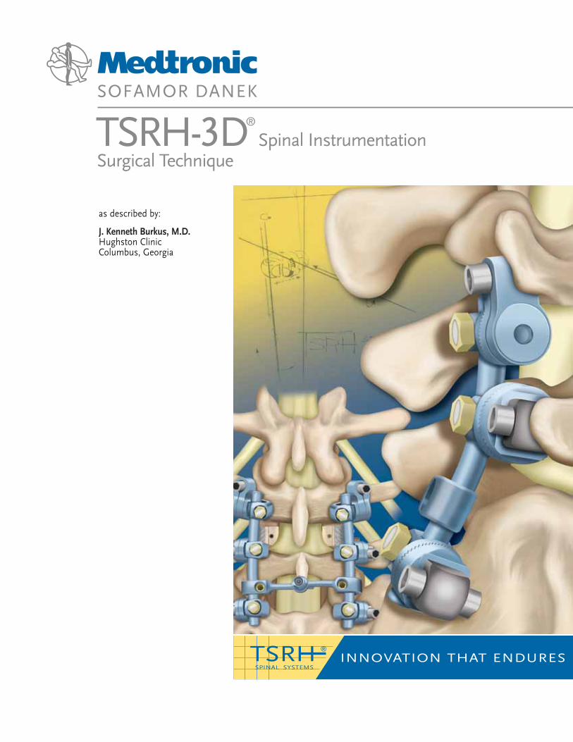
as described by:
J. Kenneth Burkus, M.D.Hughston ClinicColumbus, Georgia
TSRH-3D®
Spinal Instrumentation Surgical Technique
INNOVATION THAT ENDURES®TSRI I
SPINAL SYSTEMS
PREFA
CE
1
Dear Colleagues,
During my career, I have seen pedicle screws become the standard of care for treat-ing a wide variety of deformities in the thoracic and lumbosacral spine.
The pedicle screw options available to the surgical community are numerous, but one system has continuously and consistently offered a higher level of technology than all the others—the TSRH® Spinal System.
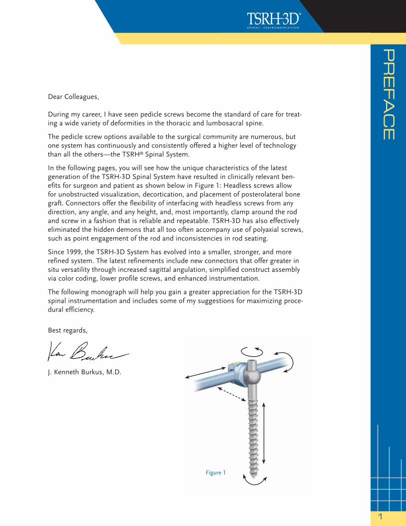
In the following pages, you will see how the unique characteristics of the latest generation of the TSRH-3D Spinal System have resulted in clinically relevant ben-efits for surgeon and patient as shown below in Figure 1: Headless screws allow for unobstructed visualization, decortication, and placement of posterolateral bone graft. Connectors offer the flexibility of interfacing with headless screws from any direction, any angle, and any height, and, most importantly, clamp around the rod and screw in a fashion that is reliable and repeatable. TSRH-3D has also effectively eliminated the hidden demons that all too often accompany use of polyaxial screws, such as point engagement of the rod and inconsistencies in rod seating.
Since 1999, the TSRH-3D System has evolved into a smaller, stronger, and more refined system. The latest refinements include new connectors that offer greater in situ versatility through increased sagittal angulation, simplified construct assembly via color coding, lower profile screws, and enhanced instrumentation.
The following monograph will help you gain a greater appreciation for the TSRH-3D spinal instrumentation and includes some of my suggestions for maximizing proce-dural efficiency.
Best regards,
J. Kenneth Burkus, M.D.
Figure 1
CO
NTEN
TS
AN
D IM
PLA
NTS
2
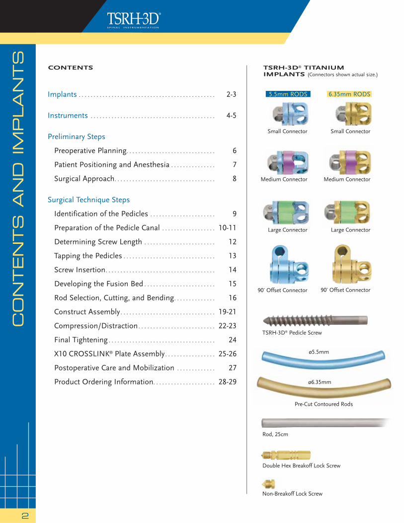
Implants . . . . . . . . . . . . . . . . . . . . . . . . . . . . . . . . . . . . . . . . . . . . . . 2-3
Instruments . . . . . . . . . . . . . . . . . . . . . . . . . . . . . . . . . . . . . . . . . . 4-5
Preliminary Steps
Preoperative Planning. . . . . . . . . . . . . . . . . . . . . . . . . . . . . . 6
Patient Positioning and Anesthesia . . . . . . . . . . . . . . . 7
Surgical Approach. . . . . . . . . . . . . . . . . . . . . . . . . . . . . . . . . . 8
Surgical Technique Steps
Identification of the Pedicles . . . . . . . . . . . . . . . . . . . . . . 9
Preparation of the Pedicle Canal . . . . . . . . . . . . . . . . . . 10-11
Determining Screw Length . . . . . . . . . . . . . . . . . . . . . . . . 12
Tapping the Pedicles . . . . . . . . . . . . . . . . . . . . . . . . . . . . . . . 13
Screw Insertion. . . . . . . . . . . . . . . . . . . . . . . . . . . . . . . . . . . . . 14
Developing the Fusion Bed . . . . . . . . . . . . . . . . . . . . . . . . 15
Rod Selection, Cutting, and Bending. . . . . . . . . . . . . . 16
Construct Assembly. . . . . . . . . . . . . . . . . . . . . . . . . . . . . . . . 19-21
Compression/Distraction. . . . . . . . . . . . . . . . . . . . . . . . . . 22-23
Final Tightening . . . . . . . . . . . . . . . . . . . . . . . . . . . . . . . . . . . . 24
X10 CROSSLINK® Plate Assembly. . . . . . . . . . . . . . . . . 25-26
Postoperative Care and Mobilization . . . . . . . . . . . . . 27
Product Ordering Information. . . . . . . . . . . . . . . . . . . . . 28-29
Rod, 25cm
Small Connector
Medium Connector
Double Hex Breakoff Lock Screw
Large Connector
Small Connector
90˚ Offset Connector
TSRH-3D® Pedicle Screw
TSRH-3D® TITANIUM IMPLANTS (Connectors shown actual size.)
Medium Connector
Large Connector
90˚ Offset Connector
5.5mm RODS 6.35mm RODS
ø5.5mm
ø6.35mm
Pre-Cut Contoured Rods
Non-Breakoff Lock Screw
CONTENTS
FEATU
RES A
ND
BEN
EFIT
S
3
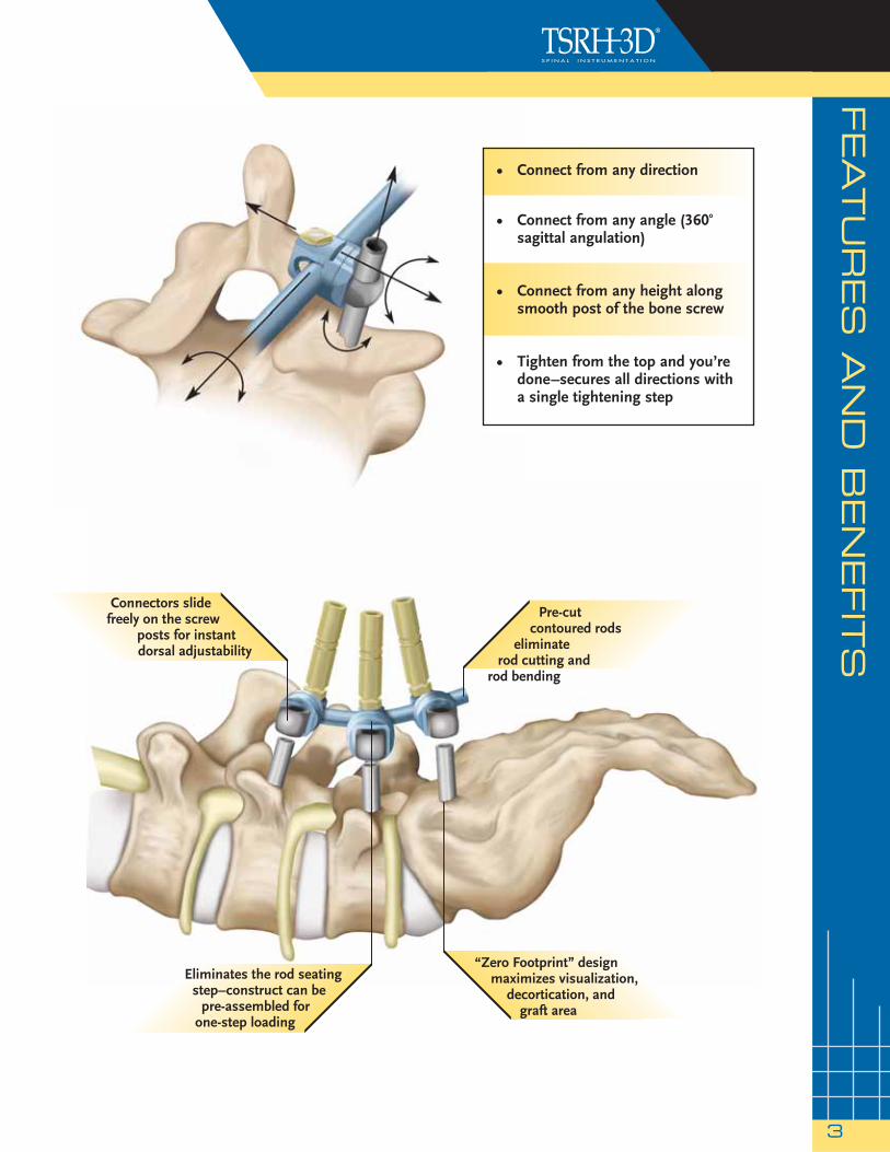
Pre-cut contoured rods
eliminate rod cutting and
rod bending
Connectors slide freely on the screw
posts for instant dorsal adjustability
Eliminates the rod seating step–construct can be
pre-assembled for one-step loading
“Zero Footprint” design maximizes visualization,
decortication, and graft area
• Connect from any direction
• Connect from any angle (360o sagittal angulation)
• Connect from any height along smooth post of the bone screw
• Tighten from the top and you’re done –secures all directions with a single tightening step
INS
TR
UM
EN
TS
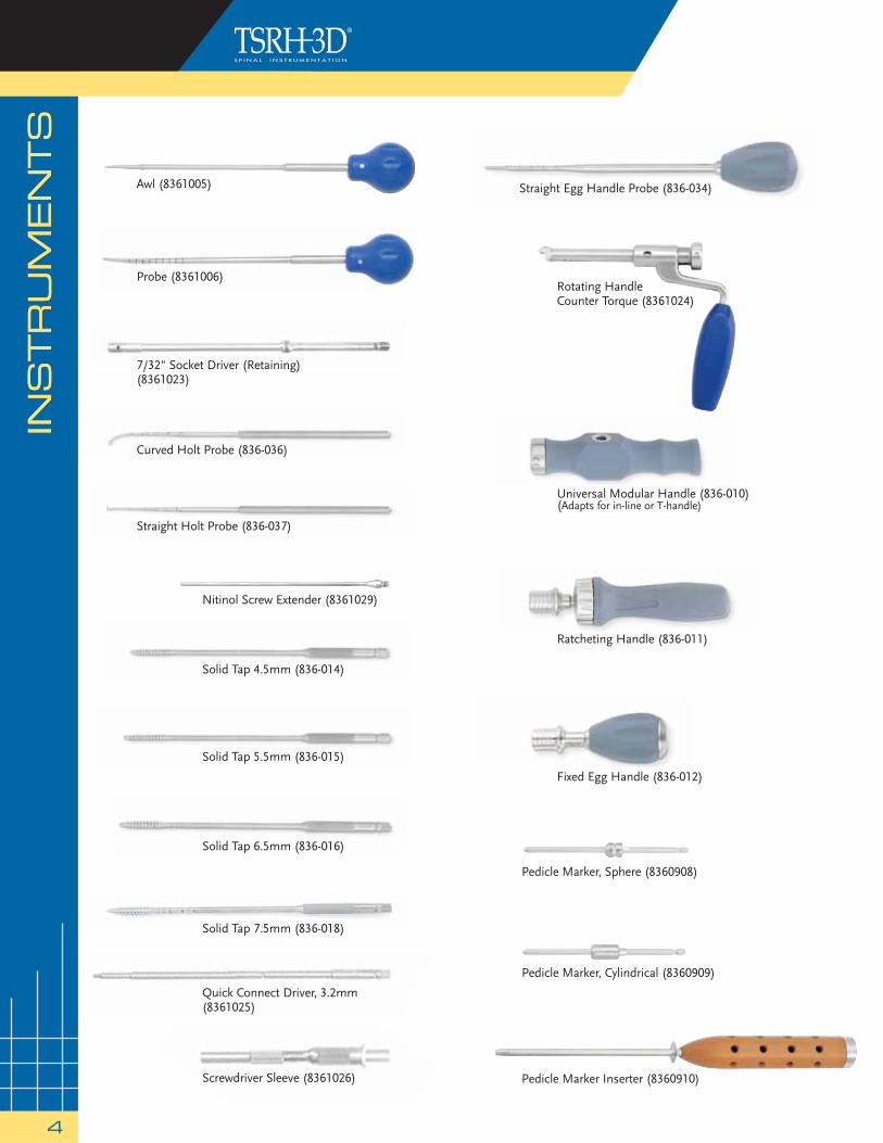
4
Rotating HandleCounter Torque (8361024)
Probe (8361006)
Ratcheting Handle (836-011)
Straight Egg Handle Probe (836-034)
Curved Holt Probe (836-036)
Straight Holt Probe (836-037)
Nitinol Screw Extender (8361029)
Solid Tap 6.5mm (836-016)
Screwdriver Sleeve (8361026)
Quick Connect Driver, 3.2mm(8361025)
7/32" Socket Driver (Retaining) (8361023)
Solid Tap 5.5mm (836-015)
Fixed Egg Handle (836-012)
Solid Tap 7.5mm (836-018)
Pedicle Marker Inserter (8360910)
Universal Modular Handle (836-010)(Adapts for in-line or T-handle)
Solid Tap 4.5mm (836-014)
Pedicle Marker, Sphere (8360908)
Pedicle Marker, Cylindrical (8360909)
INS
TR
UM
EN
TS
Awl (8361005)
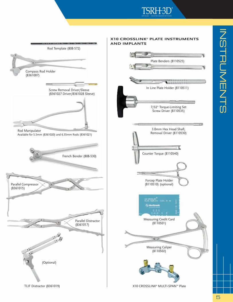
Rod Template (808-572)
X10 CROSSLINK® PLATE INSTRUMENTSAND IMPLANTS
X10 CROSSLINK® MULTI-SPAN™ Plate
Rod ManipulatorAvailable for 5.5mm (8361020) and 6.35mm Rods (8361021)
French Bender (808-530)
Parallel Compressor(8361015)
Parallel Distractor (8361017)
(Optional)
TLIF Distractor (8361019)
INSTRU
MEN
TS
5
Compass Rod Holder(8361007)
Screw Removal Driver/Sleeve(8361027 Driver/8361028 Sleeve)
Forcep Plate Holder (8110510) (optional)
7/32" Torque-Limiting SetScrew Driver (8110535)
3.0mm Hex Head Shaft,Removal Driver (8110530)
Counter Torque (8110540)
In Line Plate Holder (8110511)
Measuring Credit Card(8110501)
Measuring Caliper(8110502)
Plate Benders (8110525)
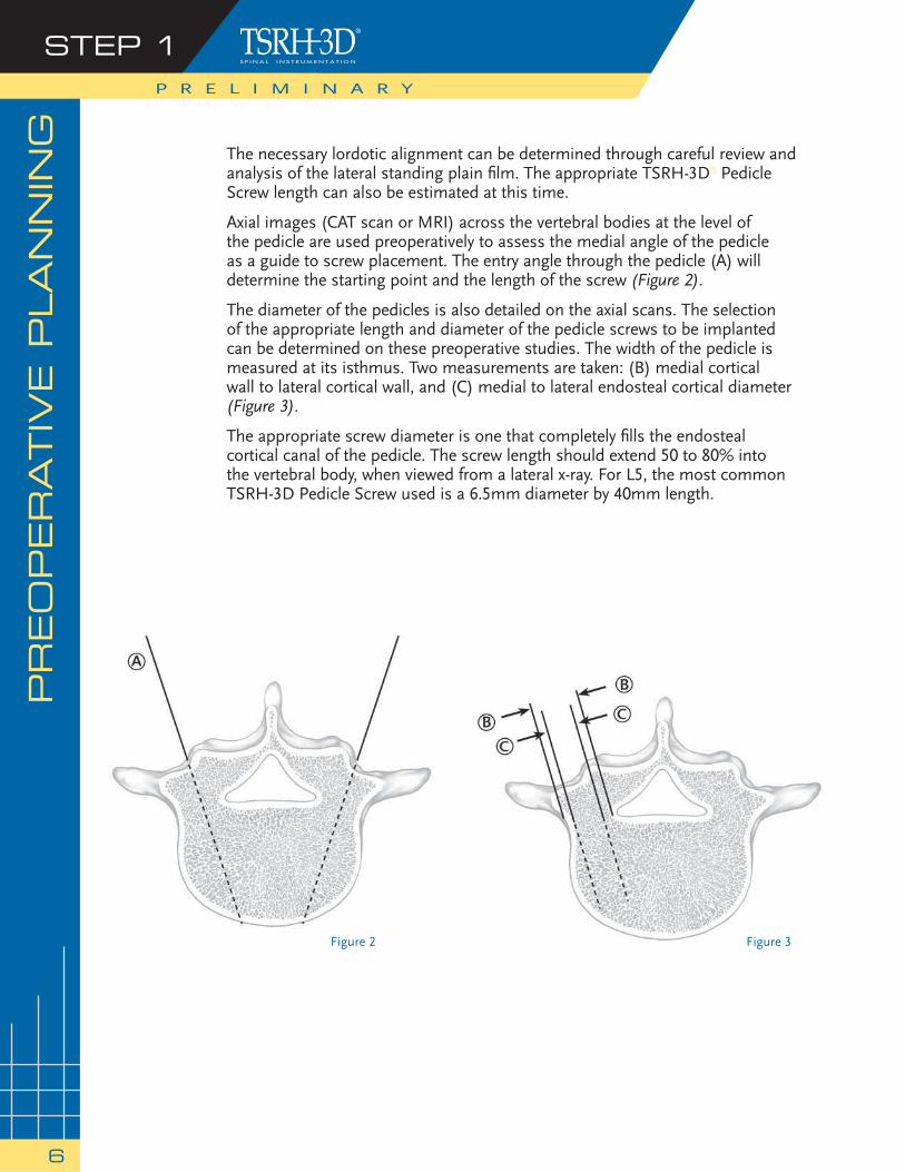
Figure 2 Figure 3
The necessary lordotic alignment can be determined through careful review and analysis of the lateral standing plain fi lm. The appropriate TSRH-3D® Pedicle Screw length can also be estimated at this time.
Axial images (CAT scan or MRI) across the vertebral bodies at the level of the pedicle are used preoperatively to assess the medial angle of the pedicle as a guide to screw placement. The entry angle through the pedicle (A) will determine the starting point and the length of the screw (Figure 2).
The diameter of the pedicles is also detailed on the axial scans. The selection of the appropriate length and diameter of the pedicle screws to be implanted can be determined on these preoperative studies. The width of the pedicle is measured at its isthmus. Two measurements are taken: (B) medial cortical wall to lateral cortical wall, and (C) medial to lateral endosteal cortical diameter (Figure 3).
The appropriate screw diameter is one that completely fi lls the endosteal cortical canal of the pedicle. The screw length should extend 50 to 80% into the vertebral body, when viewed from a lateral x-ray. For L5, the most common TSRH-3D Pedicle Screw used is a 6.5mm diameter by 40mm length.
PR
EO
PER
ATIV
E P
LA
NN
ING
STEP 1P R E L I M I N A R Y
6
PATIE
NT P
OSIT
ION
ING
& A
NESTH
ESIA
STEP 2
7
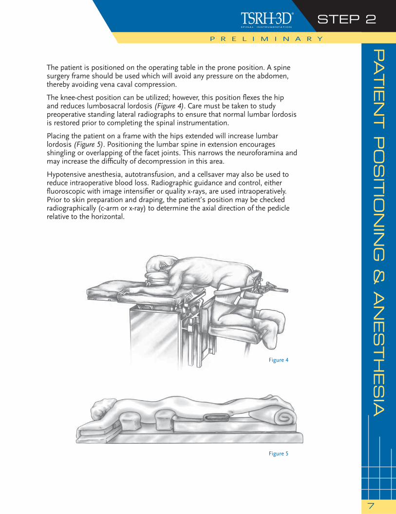
The patient is positioned on the operating table in the prone position. A spine surgery frame should be used which will avoid any pressure on the abdomen, thereby avoiding vena caval compression.
The knee-chest position can be utilized; however, this position fl exes the hip and reduces lumbosacral lordosis (Figure 4). Care must be taken to study preoperative standing lateral radiographs to ensure that normal lumbar lordosis is restored prior to completing the spinal instrumentation.
Placing the patient on a frame with the hips extended will increase lumbar lordosis (Figure 5). Positioning the lumbar spine in extension encourages shingling or overlapping of the facet joints. This narrows the neuroforamina and may increase the diffi culty of decompression in this area.
Hypotensive anesthesia, autotransfusion, and a cellsaver may also be used to reduce intraoperative blood loss. Radiographic guidance and control, either fl uoroscopic with image intensifi er or quality x-rays, are used intraoperatively. Prior to skin preparation and draping, the patient’s position may be checked radiographically (c-arm or x-ray) to determine the axial direction of the pedicle relative to the horizontal.
Figure 5
Figure 4
P R E L I M I N A R Y
SU
RG
ICA
L A
PPRO
AC
H
The surgical approach is carried out through a standard midline incision to the spinal column over the anatomic position of the spinous processes. The incision should be long enough to ensure exposure of the levels to be fused. Initially, the positions of the spinous processes are identifi ed through palpation, and the lumbar fascia is incised on the sides of each of the spinous processes. The supraspinous and interspinous ligaments should be preserved, particularly above the area of instrumentation, as these are important posterior stabilizers.
Meticulous subperiosteal exposure of the posterior elements is performed. The paraspinal musculature is detached to the outer margins of the transverse processes.
When indicated, soft tissue and bony decompression are performed to relieve neurological compression. The capsule and articular cartilage of the facet joints to be included in the fusion are excised. When necessary, decompressive laminectomies are performed to correct any stenosis in the central canal along with lateral recess and neural foraminal decompressions.
Decompression can now be carried out as needed.
STEP 3P R E L I M I N A R Y
8
IDEN
TIF
ICATIO
N O
F T
HE P
ED
ICLES
STEP 1
9
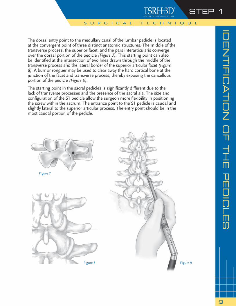
The dorsal entry point to the medullary canal of the lumbar pedicle is located at the convergent point of three distinct anatomic structures. The middle of the transverse process, the superior facet, and the pars interarticularis converge over the dorsal portion of the pedicle (Figure 7). This starting point can also be identifi ed at the intersection of two lines drawn through the middle of the transverse process and the lateral border of the superior articular facet (Figure 8). A burr or ronguer may be used to clear away the hard cortical bone at the junction of the facet and transverse process, thereby exposing the cancellous portion of the pedicle (Figure 9).
The starting point in the sacral pedicles is signifi cantly different due to the lack of transverse processes and the presence of the sacral ala. The size and confi guration of the S1 pedicle allow the surgeon more fl exibility in positioning the screw within the sacrum. The entrance point to the S1 pedicle is caudal and slightly lateral to the superior articular process. The entry point should be in the most caudal portion of the pedicle.
Figure 7
Figure 8 Figure 9
S U R G I C A L T E C H N I Q U E
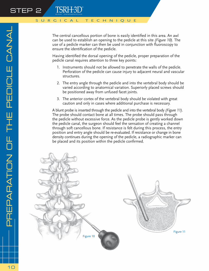
The central cancellous portion of bone is easily identifi ed in this area. An awl can be used to establish an opening to the pedicle at this site (Figure 10). The use of a pedicle marker can then be used in conjunction with fl uoroscopy to ensure the identifi cation of the pedicle.
Having identifi ed the dorsal opening of the pedicle, proper preparation of the pedicle canal requires attention to three key points:
1. Instruments should not be allowed to penetrate the walls of the pedicle. Perforation of the pedicle can cause injury to adjacent neural and vascular structures.
2. The entry angle through the pedicle and into the vertebral body should be varied according to anatomical variation. Superiorly placed screws should be positioned away from unfused facet joints.
3. The anterior cortex of the vertebral body should be violated with great caution and only in cases where additional purchase is necessary.
A blunt probe is inserted through the pedicle and into the vertebral body (Figure 11). The probe should contact bone at all times. The probe should pass through the pedicle without excessive force. As the pedicle probe is gently worked down the pedicle canal, the surgeon should feel the sensation of creating a channel through soft cancellous bone. If resistance is felt during this process, the entry position and entry angle should be re-evaluated. If resistance or change in bone density continues during the opening of the pedicle, a radiographic marker can be placed and its position within the pedicle confi rmed.
S U R G I C A L T E C H N I Q U E
STEP 2
10
PREPA
RATIO
N O
F T
HE P
ED
ICLE C
AN
AL
Figure 10
Figure 11
PREPA
RATIO
N O
F T
HE P
ED
ICLE C
AN
AL
(contin
ued)
S U R G I C A L T E C H N I Q U E
STEP 2
11
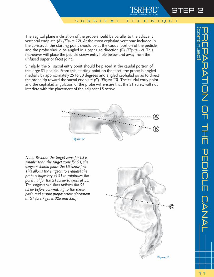
The sagittal plane inclination of the probe should be parallel to the adjacent vertebral endplate (A) (Figure 12). At the most cephalad vertebrae included in the construct, the starting point should be at the caudal portion of the pedicle and the probe should be angled in a cephalad direction (B) (Figure 12). This maneuver will place the pedicle screw entry hole below and away from the unfused superior facet joint.
Similarly, the S1 sacral entry point should be placed at the caudal portion of the large S1 pedicle. From this starting point on the facet, the probe is angled medially by approximately 25 to 30 degrees and angled cephalad so as to direct the probe tip toward the sacral endplate (C) (Figure 13). The caudal entry point and the cephalad angulation of the probe will ensure that the S1 screw will not interfere with the placement of the adjacent L5 screw.
Figure 13
Note: Because the target zone for L5 is smaller than the target zone for S1, the surgeon should place the L5 screw fi rst. This allows the surgeon to evaluate the probe’s trajectory at S1 to minimize the potential for the S1 screw to cross at L5. The surgeon can then redirect the S1 screw before committing to the screw path, and ensure proper screw placement at S1 (see Figures 32a and 32b).
Figure 12

Having opened the channel of the pedicle, all four walls of the pedicle can be palpated with a curved ball-tipped probe to ensure that the walls of the pedicle have not been violated. A straight ball-tipped probe calibrated at 10mm intervals can then be inserted into the vertebral body and the length of the pedicle and vertebral body measured to determine appropriate screw length (Figure 14).
Utilization of an image-guided system, such as the STEALTHSTATION® Treatment Guidance Platform, may be used to ensure the pedicle is prepared at the appropriate starting point, and to maintain precise angulation during pedicle screw placement. Screw lengths can also be determined by preoperatively planning on a system such as the STEALTHSTATION System.
A radiographic marker is placed through the pedicle and into the vertebral body, and its position within the confi nes of the pedicle is confi rmed with plain radiographs or fl uoroscopy. The appropriate length of the screw can also be confi rmed on lateral radiographs by referring to the marker.
If the situation arises where you can choose between two lengths of screws, choose a shorter screw. The unique feature of the TSRH-3D Pedicle Screw allows for in situ dorsal adjustment of the connector and rod construct after being loaded onto the screws.
S U R G I C A L T E C H N I Q U E
STEP 3
12
DETERM
ININ
G S
CREW
LEN
GTH
Figure 14
TA
PPIN
G T
HE P
ED
ICLES
STEP 4
13
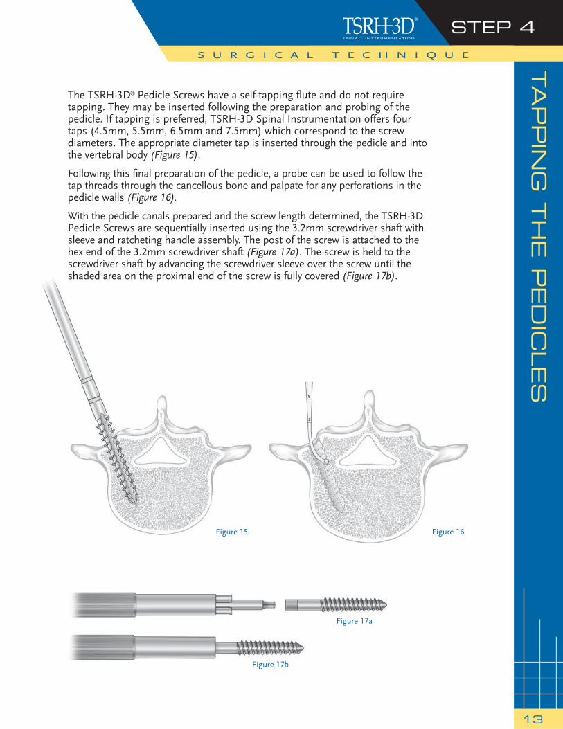
The TSRH-3D® Pedicle Screws have a self-tapping fl ute and do not require tapping. They may be inserted following the preparation and probing of the pedicle. If tapping is preferred, TSRH-3D Spinal Instrumentation offers four taps (4.5mm, 5.5mm, 6.5mm and 7.5mm) which correspond to the screw diameters. The appropriate diameter tap is inserted through the pedicle and into the vertebral body (Figure 15).
Following this fi nal preparation of the pedicle, a probe can be used to follow the tap threads through the cancellous bone and palpate for any perforations in the pedicle walls (Figure 16).
With the pedicle canals prepared and the screw length determined, the TSRH-3D Pedicle Screws are sequentially inserted using the 3.2mm screwdriver shaft with sleeve and ratcheting handle assembly. The post of the screw is attached to the hex end of the 3.2mm screwdriver shaft (Figure 17a). The screw is held to the screwdriver shaft by advancing the screwdriver sleeve over the screw until the shaded area on the proximal end of the screw is fully covered (Figure 17b).
S U R G I C A L T E C H N I Q U E
Figure 17a
Figure 17b
Figure 15 Figure 16
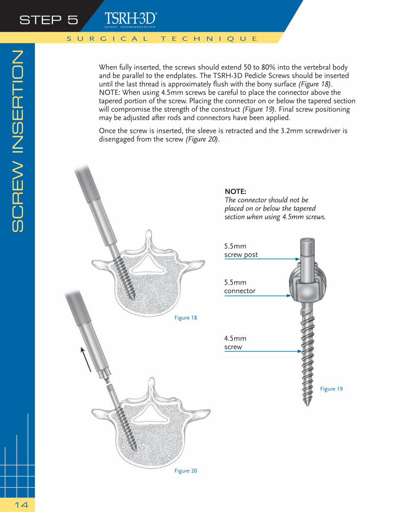
When fully inserted, the screws should extend 50 to 80% into the vertebral body and be parallel to the endplates. The TSRH-3D Pedicle Screws should be inserted until the last thread is approximately fl ush with the bony surface (Figure 18). NOTE: When using 4.5mm screws be careful to place the connector above the tapered portion of the screw. Placing the connector on or below the tapered section will compromise the strength of the construct (Figure 19). Final screw positioning may be adjusted after rods and connectors have been applied.
Once the screw is inserted, the sleeve is retracted and the 3.2mm screwdriver is disengaged from the screw (Figure 20).
S U R G I C A L T E C H N I Q U E
SC
REW
IN
SERTIO
NSTEP 5
14
Figure 18
Figure 19
Figure 20
NOTE:The connector should not be placed on or below the tapered section when using 4.5mm screws.
5.5mmscrew post
5.5mmconnector
4.5mmscrew
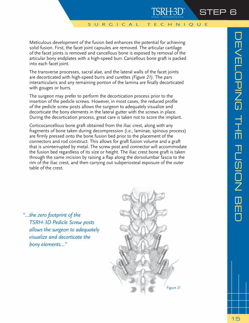
Figure 21
“… the zero footprint of the TSRH-3D Pedicle Screw posts allows the surgeon to adequately visualize and decorticate the bony elements…”
DEVELO
PIN
G T
HE F
US
ION
BED
STEP 6
15
Meticulous development of the fusion bed enhances the potential for achieving solid fusion. First, the facet joint capsules are removed. The articular cartilage of the facet joints is removed and cancellous bone is exposed by removal of the articular bony endplates with a high-speed burr. Cancellous bone graft is packed into each facet joint.
The transverse processes, sacral alae, and the lateral walls of the facet joints are decorticated with high-speed burrs and curettes (Figure 21). The pars interarticularis and any remaining portion of the lamina are fi nally decorticated with gouges or burrs.
The surgeon may prefer to perform the decortication process prior to the insertion of the pedicle screws. However, in most cases, the reduced profi le of the pedicle screw posts allows the surgeon to adequately visualize and decorticate the bony elements in the lateral gutter with the screws in place. During the decortication process, great care is taken not to score the implant.
Corticocancellous bone graft obtained from the iliac crest, along with any fragments of bone taken during decompression (i.e., laminae, spinous process) are fi rmly pressed onto the bone fusion bed prior to the placement of the connectors and rod construct. This allows for graft fusion volume and a graft that is uninterrupted by metal. The screw post and connector will accommodate the fusion bed regardless of its size or height. The iliac crest bone graft is taken through the same incision by raising a fl ap along the dorsolumbar fascia to the rim of the iliac crest, and then carrying out subperiosteal exposure of the outer table of the crest.
S U R G I C A L T E C H N I Q U E
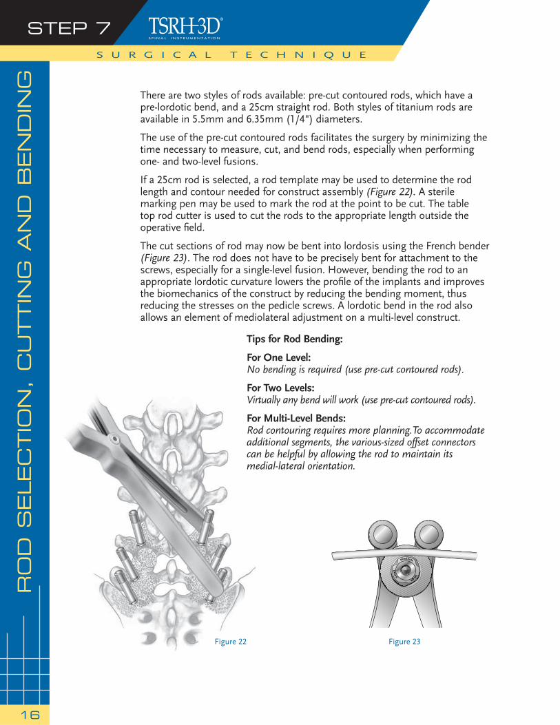
Figure 22
medium
largesmal
l
Figure 23
There are two styles of rods available: pre-cut contoured rods, which have a pre-lordotic bend, and a 25cm straight rod. Both styles of titanium rods are available in 5.5mm and 6.35mm (1/4") diameters.
The use of the pre-cut contoured rods facilitates the surgery by minimizing the time necessary to measure, cut, and bend rods, especially when performing one- and two-level fusions.
If a 25cm rod is selected, a rod template may be used to determine the rod length and contour needed for construct assembly (Figure 22). A sterile marking pen may be used to mark the rod at the point to be cut. The table top rod cutter is used to cut the rods to the appropriate length outside the operative fi eld.
The cut sections of rod may now be bent into lordosis using the French bender (Figure 23). The rod does not have to be precisely bent for attachment to the screws, especially for a single-level fusion. However, bending the rod to an appropriate lordotic curvature lowers the profi le of the implants and improves the biomechanics of the construct by reducing the bending moment, thus reducing the stresses on the pedicle screws. A lordotic bend in the rod also allows an element of mediolateral adjustment on a multi-level construct.
S U R G I C A L T E C H N I Q U E
RO
D S
ELEC
TIO
N, C
UTTIN
G A
ND
BEN
DIN
GSTEP 7
16
Tips for Rod Bending:
For One Level: No bending is required (use pre-cut contoured rods).
For Two Levels:Virtually any bend will work (use pre-cut contoured rods).
For Multi-Level Bends:Rod contouring requires more planning.To accommodateadditional segments, the various-sized offset connectors can be helpful by allowing the rod to maintain its medial-lateral orientation.
CO
NS
TR
UC
T A
SS
EM
BLY
STEP 8
17
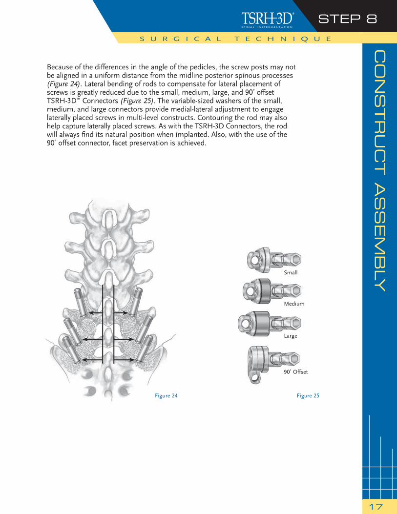
Because of the differences in the angle of the pedicles, the screw posts may not be aligned in a uniform distance from the midline posterior spinous processes (Figure 24). Lateral bending of rods to compensate for lateral placement of screws is greatly reduced due to the small, medium, large, and 90˚ offset TSRH-3D™ Connectors (Figure 25). The variable-sized washers of the small, medium, and large connectors provide medial-lateral adjustment to engage laterally placed screws in multi-level constructs. Contouring the rod may also help capture laterally placed screws. As with the TSRH-3D Connectors, the rod will always fi nd its natural position when implanted. Also, with the use of the 90˚ offset connector, facet preservation is achieved.
S U R G I C A L T E C H N I Q U E
Figure 24 Figure 25
90˚ Offset
Large
Medium
Small
STEP 8S U R G I C A L T E C H N I Q U E
18
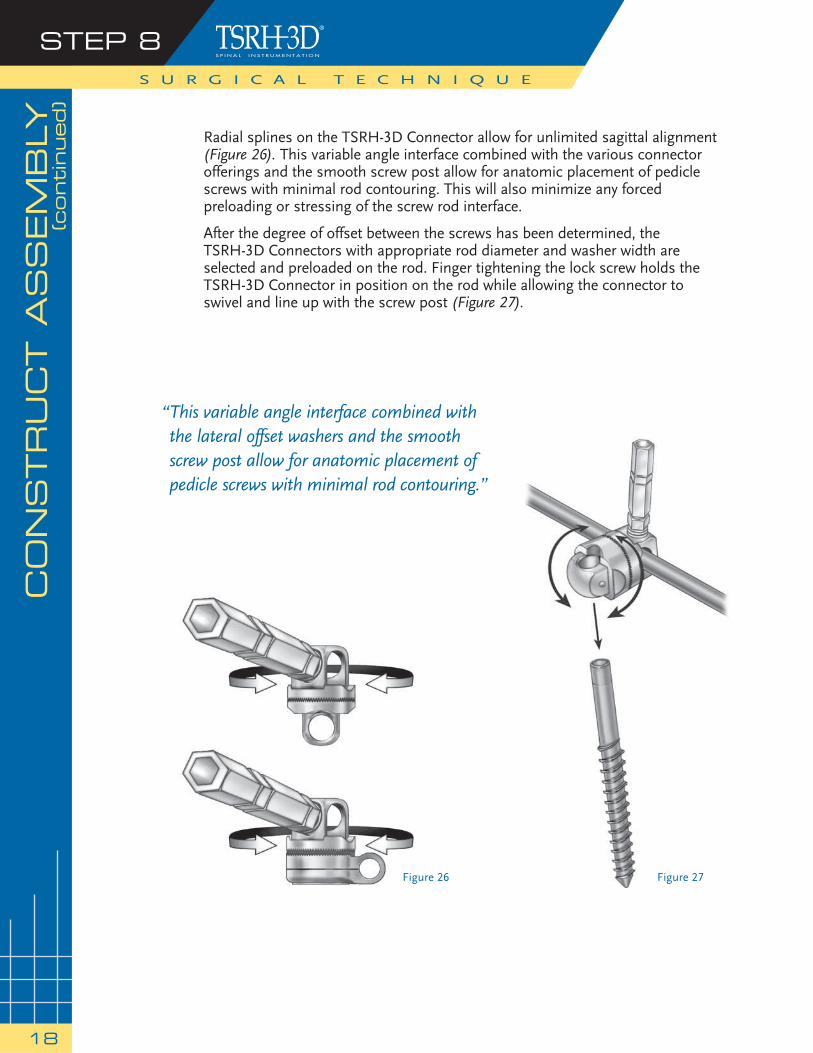
Radial splines on the TSRH-3D Connector allow for unlimited sagittal alignment (Figure 26). This variable angle interface combined with the various connector offerings and the smooth screw post allow for anatomic placement of pedicle screws with minimal rod contouring. This will also minimize any forced preloading or stressing of the screw rod interface.
After the degree of offset between the screws has been determined, the TSRH-3D Connectors with appropriate rod diameter and washer width are selected and preloaded on the rod. Finger tightening the lock screw holds the TSRH-3D Connector in position on the rod while allowing the connector to swivel and line up with the screw post (Figure 27).
CO
NS
TR
UC
T A
SS
EM
BLY
(continued)
Figure 26
“ This variable angle interface combined with the lateral offset washers and the smooth screw post allow for anatomic placement of pedicle screws with minimal rod contouring.”
Figure 27
CO
NS
TR
UC
T A
SS
EM
BLY
(contin
ued)
STEP 8
19
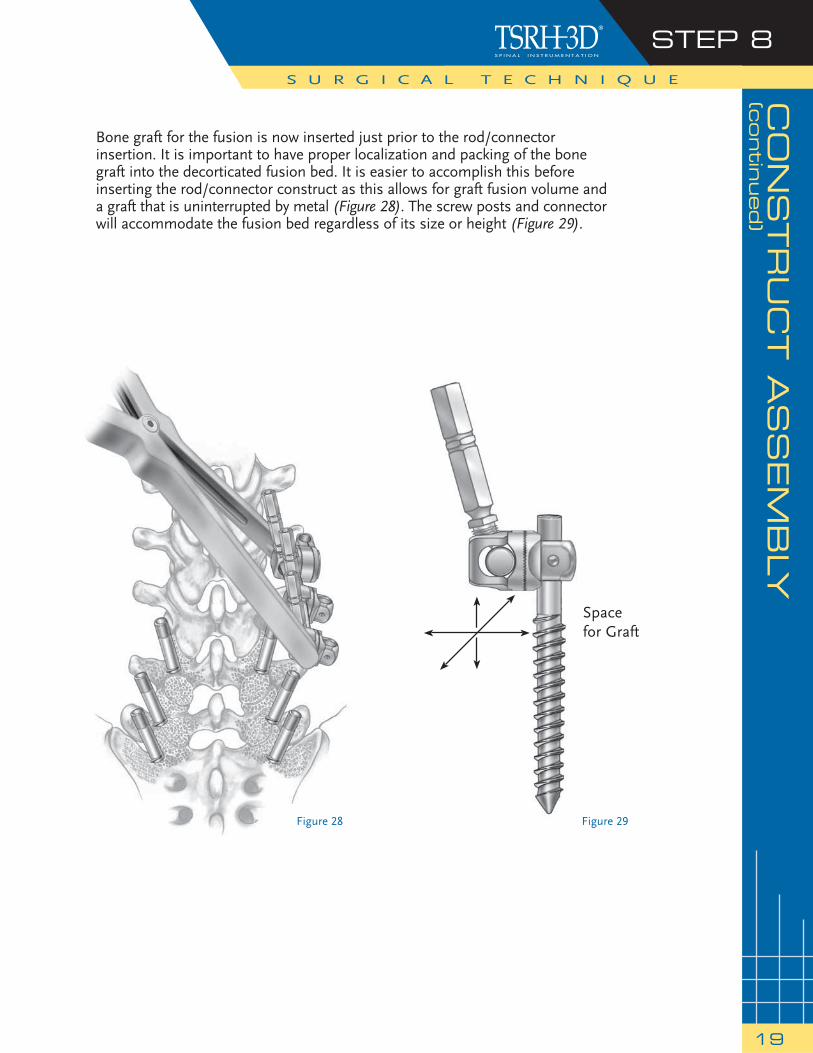
Bone graft for the fusion is now inserted just prior to the rod/connector insertion. It is important to have proper localization and packing of the bone graft into the decorticated fusion bed. It is easier to accomplish this before inserting the rod/connector construct as this allows for graft fusion volume and a graft that is uninterrupted by metal (Figure 28). The screw posts and connector will accommodate the fusion bed regardless of its size or height (Figure 29).
S U R G I C A L T E C H N I Q U E
Figure 29Figure 28
Space for Graft
STEP 8S U R G I C A L T E C H N I Q U E
20
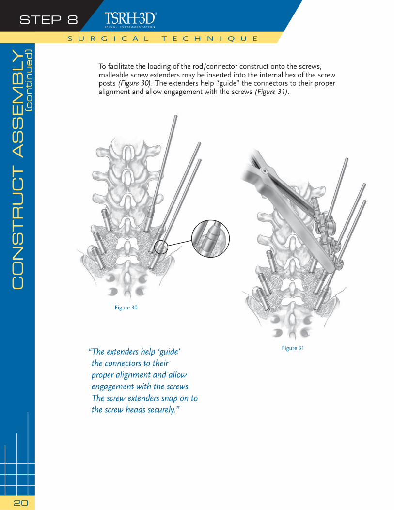
To facilitate the loading of the rod/connector construct onto the screws, malleable screw extenders may be inserted into the internal hex of the screw posts (Figure 30). The extenders help “guide” the connectors to their proper alignment and allow engagement with the screws (Figure 31).
CO
NS
TR
UC
T A
SS
EM
BLY
(continued)
Figure 30
Figure 31“ The extenders help ‘guide’ the connectors to their proper alignment and allow engagement with the screws.The screw extenders snap on to the screw heads securely.”
CO
NS
TR
UC
T A
SS
EM
BLY
(contin
ued)
STEP 8
21
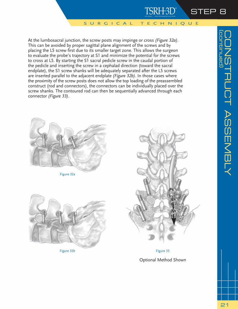
At the lumbosacral junction, the screw posts may impinge or cross (Figure 32a). This can be avoided by proper sagittal plane alignment of the screws and by placing the L5 screw fi rst due to its smaller target zone. This allows the surgeon to evaluate the probe’s trajectory at S1 and minimize the potential for the screws to cross at L5. By starting the S1 sacral pedicle screw in the caudal portion of the pedicle and inserting the screw in a cephalad direction (toward the sacral endplate), the S1 screw shanks will be adequately separated after the L5 screws are inserted parallel to the adjacent endplate (Figure 32b). In those cases where the proximity of the screw posts does not allow the top loading of the preassembled construct (rod and connectors), the connectors can be individually placed over the screw shanks. The contoured rod can then be sequentially advanced through each connector (Figure 33).
S U R G I C A L T E C H N I Q U E
Figure 32a
Figure 33Figure 32b
Optional Method Shown
STEP 9S U R G I C A L T E C H N I Q U E
22
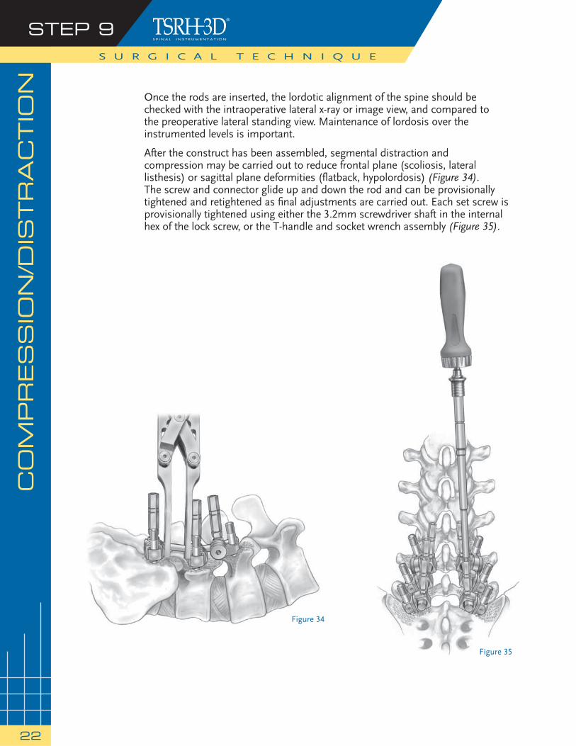
Once the rods are inserted, the lordotic alignment of the spine should be checked with the intraoperative lateral x-ray or image view, and compared to the preoperative lateral standing view. Maintenance of lordosis over the instrumented levels is important.
After the construct has been assembled, segmental distraction and compression may be carried out to reduce frontal plane (scoliosis, lateral listhesis) or sagittal plane deformities (fl atback, hypolordosis) (Figure 34). The screw and connector glide up and down the rod and can be provisionally tightened and retightened as fi nal adjustments are carried out. Each set screw is provisionally tightened using either the 3.2mm screwdriver shaft in the internal hex of the lock screw, or the T-handle and socket wrench assembly (Figure 35).
CO
MPR
ES
SIO
N/D
ISTR
AC
TIO
N
Figure 35
Figure 34
CO
MPR
ES
SIO
N/D
ISTR
AC
TIO
N(c
ontin
ued)
STEP 9
23
If the patient has been positioned in the knee-chest position, the lumbosacral lordosis is often reduced. With the implants in place but not tightened, the foot end of the table can be raised to improve the lumbosacral lordosis. Further changes in segmental lordosis can be affected by compression of the screw and connector assembly along the rod. With this maneuver, a precise amount of lordosis may be achieved prior to the fi nal tightening of the construct. A lateral radiograph or fl uoroscopy can be used to determine the sagittal contour obtained at surgery. The depth of the screws can also be checked on the lateral radiograph.
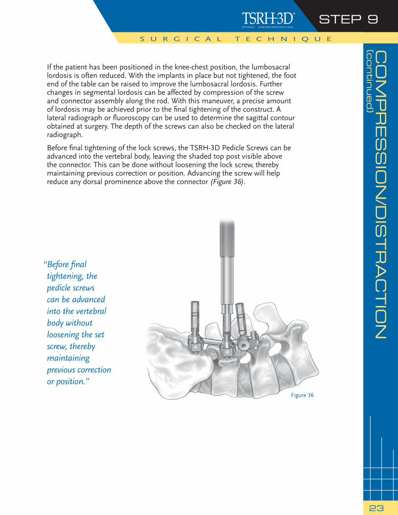
Before fi nal tightening of the lock screws, the TSRH-3D Pedicle Screws can be advanced into the vertebral body, leaving the shaded top post visible above the connector. This can be done without loosening the lock screw, thereby maintaining previous correction or position. Advancing the screw will help reduce any dorsal prominence above the connector (Figure 36).
S U R G I C A L T E C H N I Q U E
“ Before fi nal tightening, the pedicle screws can be advanced into the vertebral body without loosening the set screw, thereby maintaining previous correction or position.”
Figure 36
STEP 10S U R G I C A L T E C H N I Q U E
24
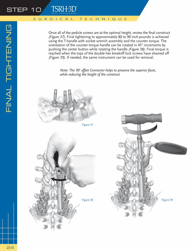
Once all of the pedicle screws are at the optimal height, review the fi nal construct (Figure 37). Final tightening to approximately 80 to 90 inch-pounds is achieved using the T-handle with socket wrench assembly and the counter torque. The orientation of the counter torque handle can be rotated in 45° increments by pushing the center button while rotating the handle (Figure 38). Final torque is reached when the tops of the double hex breakoff lock screws have sheared off (Figure 39). If needed, the same instrument can be used for removal.
Note: The 90˚ offset Connector helps to preserve the superior facet, while reducing the height of the construct.
FIN
AL T
IGH
TEN
ING
Figure 37
Figure 38 Figure 39
X10 C
RO
SS
LIN
K® P
LATE A
SS
EM
BLY
S U R G I C A L T E C H N I Q U E
STEP 11
25
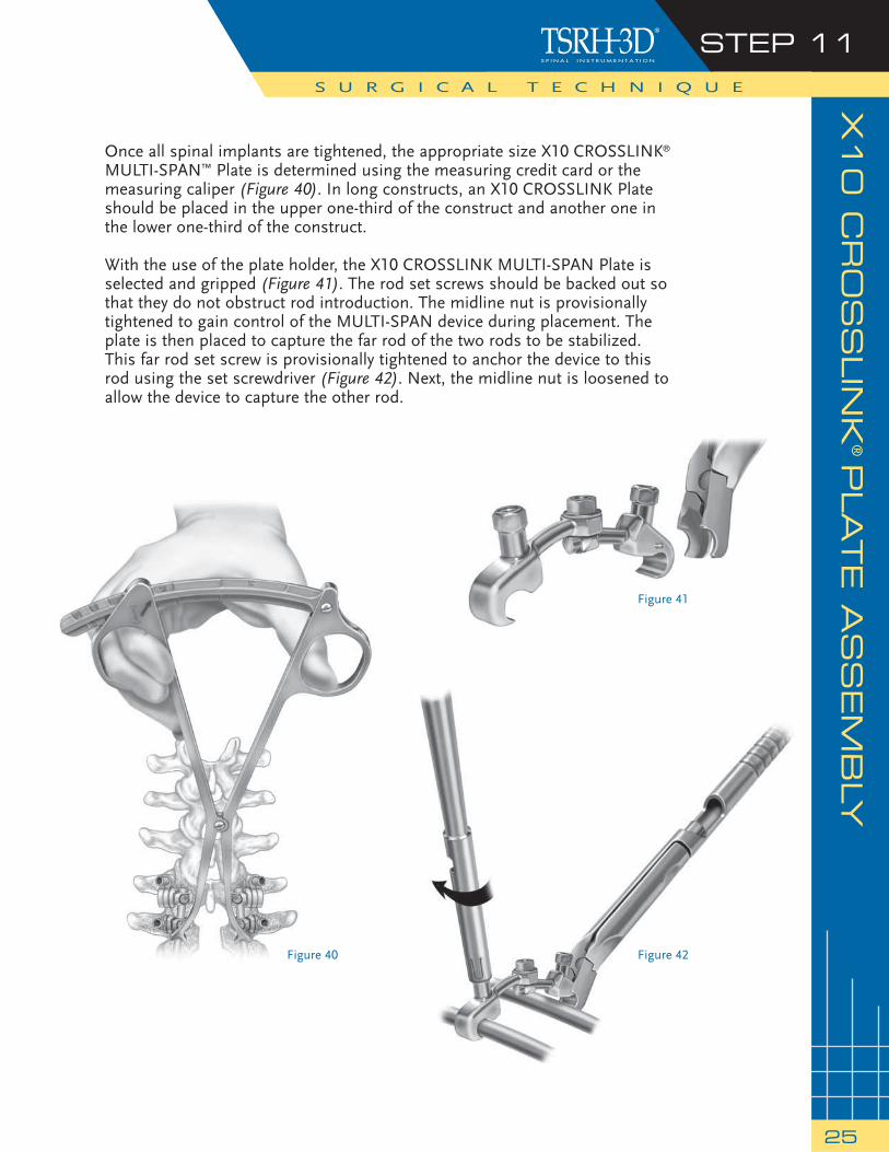
Once all spinal implants are tightened, the appropriate size X10 CROSSLINK® MULTI-SPAN™ Plate is determined using the measuring credit card or the measuring caliper (Figure 40). In long constructs, an X10 CROSSLINK Plate should be placed in the upper one-third of the construct and another one in the lower one-third of the construct.
With the use of the plate holder, the X10 CROSSLINK MULTI-SPAN Plate is selected and gripped (Figure 41). The rod set screws should be backed out so that they do not obstruct rod introduction. The midline nut is provisionally tightened to gain control of the MULTI-SPAN device during placement. The plate is then placed to capture the far rod of the two rods to be stabilized. This far rod set screw is provisionally tightened to anchor the device to this rod using the set screwdriver (Figure 42). Next, the midline nut is loosened to allow the device to capture the other rod.
Figure 40
Figure 41
Figure 42
STEP 12S U R G I C A L T E C H N I Q U E
26
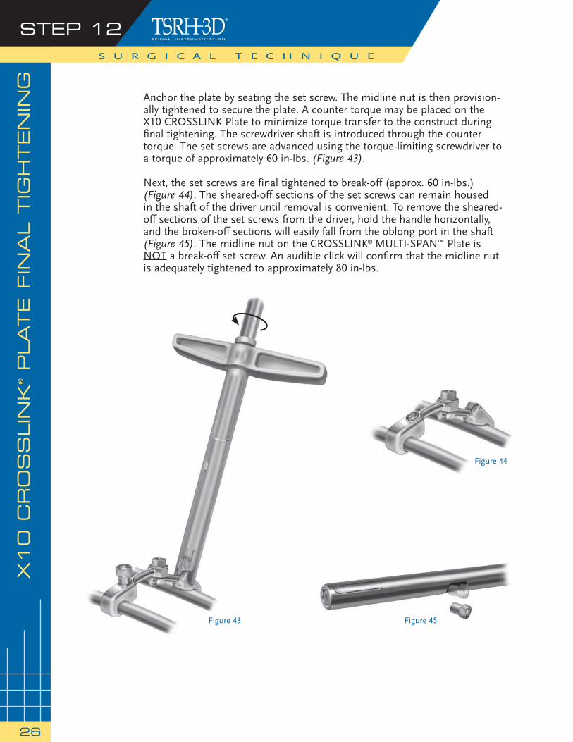
Anchor the plate by seating the set screw. The midline nut is then provision-ally tightened to secure the plate. A counter torque may be placed on the X10 CROSSLINK Plate to minimize torque transfer to the construct during final tightening. The screwdriver shaft is introduced through the counter torque. The set screws are advanced using the torque-limiting screwdriver to a torque of approximately 60 in-lbs. (Figure 43).
Next, the set screws are final tightened to break-off (approx. 60 in-lbs.)(Figure 44). The sheared-off sections of the set screws can remain housedin the shaft of the driver until removal is convenient. To remove the sheared-off sections of the set screws from the driver, hold the handle horizontally, and the broken-off sections will easily fall from the oblong port in the shaft (Figure 45). The midline nut on the CROSSLINK® MULTI-SPAN™ Plate is NOT a break-off set screw. An audible click will confirm that the midline nut is adequately tightened to approximately 80 in-lbs.
X10 C
RO
SS
LIN
K® PLATE F
INA
L T
IGH
TEN
ING
Figure 43
Figure 44
Figure 45

PO
STO
PER
ATIV
E C
AR
E A
ND
MO
BIL
IZATIO
N
27
Patients must be warned to avoid physical activities that would place excessive stress upon the implant or bone graft, which could delay or prevent healing. However, regular, graduated, mild to moderate activity is benefi cial to bone formation, particularly when the vertebrae have been adequately stabilized internally. Patients should use adequate external support until bony fusion has been established. They should be instructed in the proper methods of getting in and out of bed, getting up from a sitting position, etc.
Please see the package insert for Warnings, Precautions, and Possible Adverse Events.
NOTE: Implant Explantation The TSRH-3D Connectors may be removed by applying the 7/32 socket driver from the TSRH-3D Instrument Set to the connector lock screw and turning counter-clockwise until the lock screw is removed (see Figure 36, page 23). The TSRH-3D Pedicle Screws may be removed by applying the 3.2mm hex driver from the TSRH-3D Instrument Set to the screw and turning counter-clockwise until the screw is removed from the pedicle (see Figure 18, page 14).
28
PR
OD
UC
T IN
FO
RM
ATIO
N
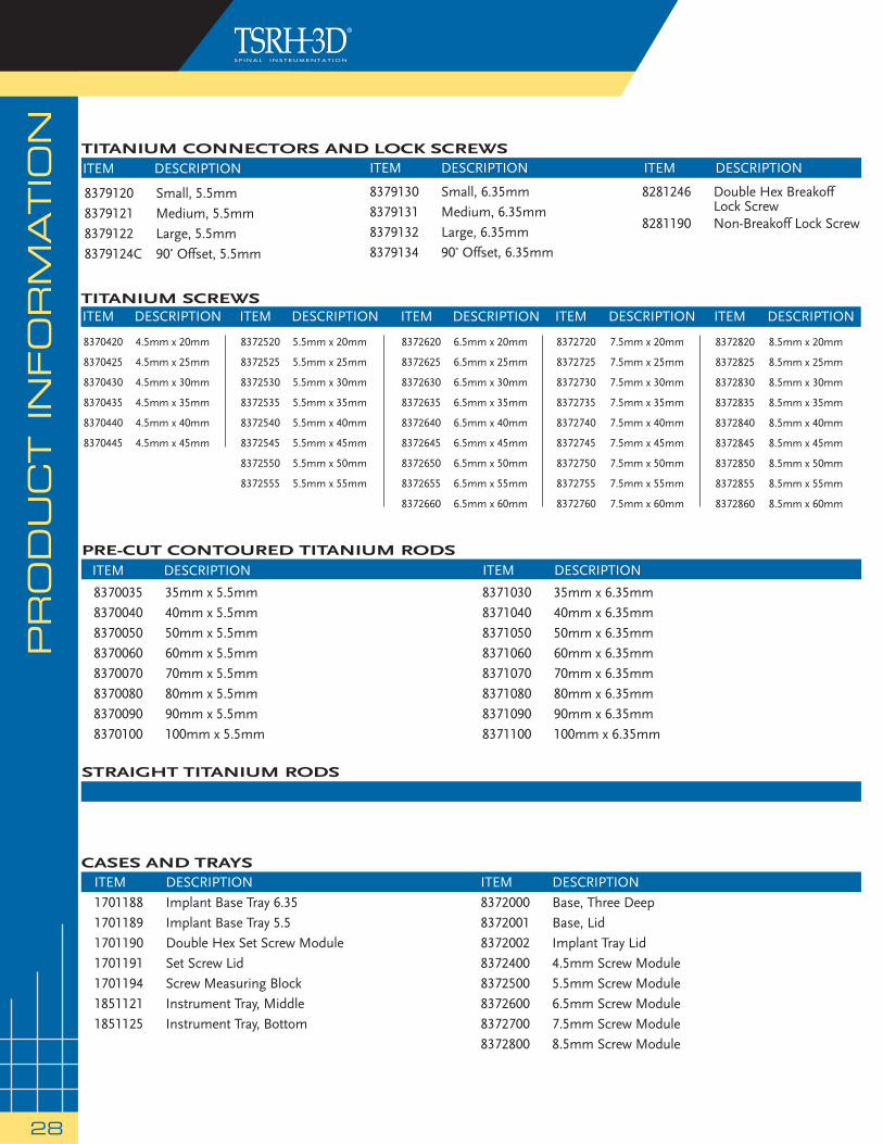
8379120 Small, 5.5mm8379121 Medium, 5.5mm8379122 Large, 5.5mm8379124C 90˚ Offset, 5.5mm
8379130 Small, 6.35mm8379131 Medium, 6.35mm8379132 Large, 6.35mm8379134 90˚ Offset, 6.35mm
8281246 Double Hex Breakoff Lock Screw 8281190 Non-Breakoff Lock Screw
TITANIUM CONNECTORS AND LOCK SCREWS
ITEM DESCRIPTION1701188 Implant Base Tray 6.351701189 Implant Base Tray 5.51701190 Double Hex Set Screw Module1701191 Set Screw Lid1701194 Screw Measuring Block1851121 Instrument Tray, Middle1851125 Instrument Tray, Bottom
ITEM DESCRIPTION8372000 Base, Three Deep8372001 Base, Lid8372002 Implant Tray Lid8372400 4.5mm Screw Module8372500 5.5mm Screw Module8372600 6.5mm Screw Module8372700 7.5mm Screw Module8372800 8.5mm Screw Module
CASES AND TRAYS
PRE-CUT CONTOURED TITANIUM RODS
8370035 35mm x 5.5mm8370040 40mm x 5.5mm8370050 50mm x 5.5mm8370060 60mm x 5.5mm8370070 70mm x 5.5mm8370080 80mm x 5.5mm8370090 90mm x 5.5mm8370100 100mm x 5.5mm
8371030 35mm x 6.35mm8371040 40mm x 6.35mm8371050 50mm x 6.35mm8371060 60mm x 6.35mm8371070 70mm x 6.35mm8371080 80mm x 6.35mm8371090 90mm x 6.35mm8371100 100mm x 6.35mm
ITEM DESCRIPTION ITEM DESCRIPTION
ITEM DESCRIPTION ITEM DESCRIPTION ITEM DESCRIPTION
TITANIUM SCREWS
8372620 6.5mm x 20mm
8372625 6.5mm x 25mm
8372630 6.5mm x 30mm
8372635 6.5mm x 35mm
8372640 6.5mm x 40mm
8372645 6.5mm x 45mm
8372650 6.5mm x 50mm
8372655 6.5mm x 55mm
8372660 6.5mm x 60mm
ITEM DESCRIPTION
8370420 4.5mm x 20mm
8370425 4.5mm x 25mm
8370430 4.5mm x 30mm
8370435 4.5mm x 35mm
8370440 4.5mm x 40mm
8370445 4.5mm x 45mm
ITEM DESCRIPTION ITEM DESCRIPTION
8372720I 7.5mm x 20mmT
8372725 7.5mm x 25mm
8372730I 7.5mm x 30mmT
8372735 7.5mm x 35mm
8372740 7.5mm x 40mm
8372745 7.5mm x 45mm
8372750 7.5mm x 50mm
8372755 7.5mm x 55mm
8372760 7.5mm x 60mm
ITEM DESCRIPTION
8372820I 8.5mm x 20mmT
8372825 8.5mm x 25mm
8372830I 8.5mm x 30mmT
8372835 8.5mm x 35mm
8372840 8.5mm x 40mm
8372845 8.5mm x 45mm
8372850 8.5mm x 50mm
8372855 8.5mm x 55mm
8372860 8.5mm x 60mm
8372520 5.5mm x 20mm
8372525 5.5mm x 25mm
8372530 5.5mm x 30mm
8372535 5.5mm x 35mm
8372540 5.5mm x 40mm
8372545 5.5mm x 45mm
8372550 5.5mm x 50mm
8372555 5.5mm x 55mm
ITEM DESCRIPTION
STRAIGHT TITANIUM RODS
VERTEB
RA
L B
OD
Y R
ED
UC
TIO
N P
RO
DU
CT IN
FO
RM
ATIO
N
29
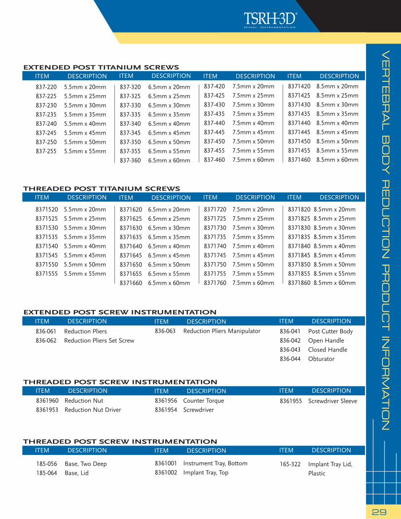
EXTENDED POST TITANIUM SCREWS
837-220 5.5mm x 20mm837-225 5.5mm x 25mm837-230 5.5mm x 30mm 837-235 5.5mm x 35mm 837-240 5.5mm x 40mm 837-245 5.5mm x 45mm 837-250 5.5mm x 50mm837-255 5.5mm x 55mm
ITEM DESCRIPTION
837-320 6.5mm x 20mm837-325 6.5mm x 25mm837-330 6.5mm x 30mm 837-335 6.5mm x 35mm 837-340 6.5mm x 40mm 837-345 6.5mm x 45mm 837-350 6.5mm x 50mm 837-355 6.5mm x 55mm837-360 6.5mm x 60mm
ITEM DESCRIPTION
837-420 7.5mm x 20mm837-425 7.5mm x 25mm837-430 7.5mm x 30mm837-435 7.5mm x 35mm 837-440 7.5mm x 40mm 837-445 7.5mm x 45mm 837-450 7.5mm x 50mm 837-455 7.5mm x 55mm 837-460 7.5mm x 60mm
ITEM DESCRIPTION
EXTENDED POST SCREW INSTRUMENTATION
836-061 Reduction Pliers836-062 Reduction Pliers Set Screw
836-063 Reduction Pliers Manipulator 836-041 Post Cutter Body 836-042 Open Handle 836-043 Closed Handle 836-044 Obturator
ITEM DESCRIPTION
8361960 Reduction Nut8361953 Reduction Nut Driver
ITEM DESCRIPTION
ITEM DESCRIPTION
8361956 Counter Torque8361954 Screwdriver
185-056 Base, Two Deep185-064 Base, Lid
8361001 Instrument Tray, Bottom8361002 Implant Tray, Top
165-322 Implant Tray Lid, Plastic
ITEM DESCRIPTIONITEM DESCRIPTIONITEM DESCRIPTION
ITEM DESCRIPTION
ITEM DESCRIPTION
8361955 Screwdriver Sleeve
ITEM DESCRIPTIONTHREADED POST SCREW INSTRUMENTATION
THREADED POST SCREW INSTRUMENTATION
THREADED POST TITANIUM SCREWS
8371520 5.5mm x 20mm8371525 5.5mm x 25mm8371530 5.5mm x 30mm8371535 5.5mm x 35mm8371540 5.5mm x 40mm8371545 5.5mm x 45mm8371550 5.5mm x 50mm8371555 5.5mm x 55mm
ITEM DESCRIPTION
8371620 6.5mm x 20mm8371625 6.5mm x 25mm8371630 6.5mm x 30mm8371635 6.5mm x 35mm8371640 6.5mm x 40mm8371645 6.5mm x 45mm8371650 6.5mm x 50mm8371655 6.5mm x 55mm8371660 6.5mm x 60mm
ITEM DESCRIPTION
8371720 7.5mm x 20mm8371725 7.5mm x 25mm8371730 7.5mm x 30mm8371735 7.5mm x 35mm8371740 7.5mm x 40mm8371745 7.5mm x 45mm8371750 7.5mm x 50mm8371755 7.5mm x 55mm8371760 7.5mm x 60mm
ITEM DESCRIPTION
8371820 8.5mm x 20mm8371825 8.5mm x 25mm8371830 8.5mm x 30mm8371835 8.5mm x 35mm8371840 8.5mm x 40mm8371845 8.5mm x 45mm8371850 8.5mm x 50mm8371855 8.5mm x 55mm8371860 8.5mm x 60mm
ITEM DESCRIPTION
8371420 8.5mm x 20mm8371425 8.5mm x 25mm8371430 8.5mm x 30mm8371435 8.5mm x 35mm 8371440 8.5mm x 40mm 8371445 8.5mm x 45mm 8371450 8.5mm x 50mm 8371455 8.5mm x 55mm 8371460 8.5mm x 60mm
ITEM DESCRIPTION
PURPOSE:
The TSRH® Spinal System is intended to help provide immobilization and stabilization of spinal segments as an adjunct to fusion of the thoracic, lumbar, and/or sacral spine.
DESCRIPTION:
The TSRH® Spinal System consists of a variety of shapes and sizes of rods, hooks, screws, cross connectors, and connecting components. In addition, GDLH® rods, DYNALOK PLUS™ bolts, CD HORIZON® Low Profi le MULTI-SPAN® CROSSLINK® Plates, GDLH® rod/bolt connectors, GDLH® Variable Angle T-Bolts, and GDLH® and CD HORIZON® set screws and locking screws may be used with the TSRH® Spinal System.
The TSRH® Spinal System implant components can be rigidly locked into a variety of confi gurations, with each construct being tailor-made for the individual case. The hooks are intended for posterior use only and the staples are for anterior use only. The TSRH-3D® connectors and TSRH-3D® screws are intended for posterior use only. All CROSSLINK® Plates are for posterior use and the CROSSLINK® Axial and Offset Plates may be used anteriorly as well.
The TSRH® Spinal System implant components are fabricated from medical grade stainless steel. Alternatively, the entire system may be made out of medical grade titanium alloy. Never use stainless steel and titanium implant components in the same construct.
No warranties, express, or implied, are made. Implied warranties of merchantability and fi tness for a particular purpose or use are specifi cally excluded. See the MSD Catalog for further information about warranties and limitations of liability.
To achieve best results, do not use any of the TSRH® Spinal System implant components with components from any other system, except those components listed above, or any other manufacturer. As with all orthopaedic and neurosurgical implants, none of the TSRH® Spinal System components should ever be reused under any circumstances.
INDICATIONS, CONTRAINDICATIONS AND POSSIBLE ADVERSE EVENTS:
INDICATIONS:
When used as a pedicle screw fi xation system of the non-cervical posterior spine in skeletally mature patients, the TSRH® Spinal System is indicated for one or more of the following: (1) degenerative disc disease (defi ned as back pain of discogenic origin with degeneration of the disc confi rmed by patient history and radiographic studies), (2) degenerative spondylolisthesis with objective evidence of neurologic impairment, (3) fracture, (4) dislocation, (5) scoliosis, (6) kyphosis, (7) spinal tumor, and/or (8) failed previous fusion (pseudarthrosis).
In addition, when used as a pedicle screw fi xation system, the TSRH® Spinal System is indicated for skeletally mature patients: (1) having severe spondylolisthesis (Grades 3 and 4) of the fi fth lumbar-fi rst sacral (L5-S1) vertebral joint: (2) who are receiving fusions using autogenous bone graft only: (3) who are having the device fi xed or attached to the lumbar and sacral spine (L3 and below); and (4) who are having the device removed after the development of a solid fusion mass.
When used as a posterior, non-cervical, non-pedicle screw fi xation system, the TSRH® Spinal System is intended for the following indications: (1) degenerative disc disease (as defi ned by back pain of discogenic origin with degeneration of the disc confi rmed by patient history and radiographic studies), (2) spondylolisthesis, (3) fracture, (4) spinal deformities (i.e., scoliosis, kyphosis, and/or lordosis), (5) spinal stenosis, (6) pseudarthrosis, (7) tumor resection, and/or (8) unsuccessful previous attempts at spinal fusion.
For anterior use only the TSRH® Spinal System has the additional indications of: (1) spinal stenosis and/or, (2) spondylolysis.
CONTRAINDICATIONS:
Contraindications include, but are not limited to:
1. Active infectious process or signifi cant risk of infection (immuno compromise).
2. Signs of local infl ammation.
3. Fever or leukocytosis.
4. Morbid obesity.
5. Pregnancy.
6. Mental illness.
7. Grossly distorted anatomy caused by congenital abnormalities.
8. Any other medical or surgical condition which would preclude the potential benefi t of spinal implant surgery, such as the presence of congenital abnormalities, elevation of sedimentation rate unexplained by other diseases, elevation of white blood count (WBC), or a marked left shift in the WBC differential count.
9. Rapid joint disease, bone absorption, osteopenia, osteomalacia and/or osteoporosis. Osteoporosis or osteopenia is a relative contraindication since this condition may limit the degree of obtainable correction, stabilization, and/or the amount of mechanical fi xation.
10. Suspected or documented metal allergy or intolerance.
11. Any case not needing a bone graft and fusion.
12. Any case where the implant components selected for use would be too large or too small to achieve a successful result.
13. Any case that requires the mixing of metals from two different components or systems.
14. Any patient having inadequate tissue coverage over the operative site or inadequate bone stock or quality.
15. Any patient in which implant utilization would interfere with anatomical structures or expected physiological performance.
16. Any patient unwilling to follow postoperative instructions.
POTENTIAL ADVERSE EVENTS:
All of the possible adverse events associated with spinal fusion surgery without in strumentation are possible. With instrumentation, a list ing of potential adverse events includes, but is not limited to:
1. Early or late loosen ing of any or all of the compo nents.
2. Disassembly, bend ing, and/or breakage of any or all of the components.
3. Foreign body (allergic) reaction to implants, debris, corrosion products (from crevice, fretting, and/or general corrosion), including metallosis, staining, tumor forma tion, and/or autoimmune disease.
4. Pressure on the skin from component parts in patients with inadequate tis sue cov erage over the implant possibly causing skin pene tration, irritation, fi brosis, necrosis, and/or pain. Bursitis. Tissue or nerve damage caused by improper positioning and placement of implants or instruments.
5. Post-operative change in spinal cur vature, loss of cor rec tion, height, and/or reduc tion.
6. Infection.
7. Dural tears, pseudomeningocele, fi stula, persistent CSF leakage, meningitis.
8. Loss of neurological function (e.g., sensory and/or motor), including paralysis (complete or incomplete), dysesthe sias, hyperesthesia, anesthesia, paresthesia, appear ance of radiculopa thy, and/or the de velopment or con tinuation of pain, numb ness, neuroma, spasms, sensory loss, tingling sensation, and/or visual defi cits.
9. Cauda equina syndrome, neuropathy, neurological defi cits (transient or permanent), paraplegia, paraparesis, refl ex defi cits, irritation, arachnoiditis, and/or muscle loss.
10. Urinary retention or loss of bladder control or other types of urological system compromise.
11. Scar formation possibly causing neurological compromise or compression around nerves and/or pain.
12. Fracture, microfracture, resorption, damage, or pene tration of any spinal bone (including the sacrum, pedicles, and/or vertebral body) and/or bone graft or bone graft harvest site at, above, and/or be low the level of surgery. Retropulsed graft.
13. Herniated nucleus pulposus, disc disruption or degeneration at, above, or below the level of surgery.
14. Non-union (or pseud arthrosis). Delayed union. Mal-union.
15. Cessation of any poten tial growth of the operated por tion of the spine.
16. Loss of or increase in spinal mobility or function.
17. Inability to perform the activities of daily living.
18. Bone loss or decrease in bone density, possibly caused by stress shield ing.
19. Graft donor site compli cations including pain, fracture, or wound heal ing problems.
20. Ileus, gastri tis, bowel obstruction or loss of bowel control or other types of gastrointestinal system compromise.
21. Hemorrhage, hematoma, occlusion, seroma, edema, hypertension, embolism, stroke, excessive bleed ing, phlebitis, wound necrosis, wound dehiscence, damage to blood vessels, or other types of cardiovascular system compromise.
22. Reproductive system compromise, including sterility, loss of con sortium, and sexual dysfunction.
23. Development of respira tory problems, e.g. pul monary embolism, atelectasis, bron chitis, pneumo-nia, etc.
24. Change in mental status.
25. Death.
Note: Additional surgery may be necessary to correct some of these potential adverse events.
WARNING AND PRECAUTIONS:
WARNING: The safety and effectiveness of pedicle screw spinal systems have been established only for spinal conditions with signifi cant mechanical instability or deformity requiring fusion with instrumentation. These conditions are signifi cant mechanical instability or deformity of the thoracic, lumbar, and sacral spine secondary to degenerative spondylolisthesis with objective evidence of neurologic impairment, fracture, dislocation, scoliosis, kyphosis, spinal tumor, and failed previous fusion (pseudarthrosis). The safety and effectiveness of this device for any other conditions are unknown.
PRECAUTION: The implantation of pedicle screw spinal systems should be performed only by experienced spinal surgeons with specifi c training in the use of this pedicle screw spinal system because this is a technically demanding procedure presenting a risk of serious injury to the patient.
A successful result is not always achieved in every surgical case. This fact is especially true in spinal surgery where many extenuating circumstances may compromise the results. This device system is not intended to be the sole means of spinal support. Use of this product without a bone graft or in cases that develop into a non-union will not be successful. No spinal implant can withstand body loads without the support of bone. In this event, bending, loosening, disassembly and/or breakage of the device(s) will eventually occur.
Preoperative and operating procedures, including knowledge of surgical techniques, good reduction, and proper selection and placement of the implants are important considerations in the successful utilization of the system by the surgeon. Further, the proper selection and compliance of the patient will greatly affect the results. Patients who smoke have been shown to have an increased incidence of non-unions. These patients should be advised of this fact and warned of this consequence. Obese, malnourished, and/or alcohol abuse patients are also poor candidates for spine fusion. Patients with poor muscle and bone quality and/or nerve paralysis are also poor candidates for spine fusion.
PHYSICIAN NOTE: Although the physician is the learned intermediary between the company and the patient, the important medical information given in this document should be conveyed to the patient.
CAUTION: For maximum strength, whenever possible, use a continuos rod instead of connecting two rods in a series with a connector.
CAUTION: Federal law (USA) restricts these devices to sale by or on the order of a physician.
CAUTION: FOR USE ON OR BY THE ORDER OF A PHYSICIAN ONLY.
Other preoperative, intraoperative, and postoperative warnings and precautions are as follows:
IMPLANT SELECTION:
The selection of the proper size, shape and design of the implant for each patient is crucial to the success of the procedure. Metallic surgical implants are subject to repeated stresses in use, and their strength is limited by the need to adapt the design to the size and shape of human bones. Unless great care is taken in patient selection, proper placement of the implant, and postoperative management to minimize stresses on the implant, such stresses may cause metal fatigue and consequent breakage, bending or loosening of the device before the healing process is complete, which may result in further injury or the need to remove the device prematurely.
PREOPERATIVE:
1. Only patients that meet the criteria described in the indications should be selected.
2. Patient conditions and/or predispositions such as those addressed in the aforementioned contraindications should be avoided.
3. Care should be used in the handling and storage of the implant component. The implants should not be scratched or otherwise damaged. Implants and instruments should be protected during storage, especially from corrosive environments.
4. An adequate inventory of implants should be available at the time of surgery, normally a quantity in excess of what is expected to be used.
5. Since mechanical parts are involved, the surgeon should be familiar with the various components before using the equipment and should personally assemble the devices to verify that all parts
30
IMPO
RTA
NT IN
FO
RM
ATIO
N O
N T
HE T
SR
H® S
PIN
AL S
YS
TEM
IMPO
RTA
NT IN
FO
RM
ATIO
N O
N T
HE T
SR
H® S
PIN
AL S
YS
TEM
31
and necessary instruments are present before the surgery begins. The TSRH® Spinal System components (described in the DESCRIPTION section) are not to be combined with the components from another manufacturer. Different metal types should never be used together.
6. All components and instruments should be cleaned and sterilized before use. Additional sterile components should be available in case of an unexpected need.
INTRAOPERATIVE:
1. Extreme caution should be used around the spinal cord and nerve roots. This admonition is especially true when inserting hooks and screws. Damage to the nerves will cause loss of neurological functions.
2. Breakage, slippage, or misuse of instruments or implant components may cause injury to the patient or operative personnel.
3. The rods should not be repeatedly or excessively bent. The rods should not be reverse bent in the same location. Use great care to insure that the implant surfaces are not scratched or notched, since such actions may reduce the functional strength of the construct. If the rods are cut to length, they should be cut in such a way as to create a fl at, non-sharp surface perpendicular to the midline of the rod. Cut the rods outside the operative fi eld. Whenever possible, pre-cut rods of the length needed.
4. Do not use the TSRH® hook trials in any type of prying action. The trial may bend or break, especially at the tip. Also, the trial or other nearby hardware may suddenly change position, possibly causing damage or injury.
5. Whenever possible or necessary, an imaging system should be utilized to facilitate surgery.
6. To insert a screw properly, a guide wire should fi rst be used, followed by a sharp tap. Caution: Do not overtap or use a screw/bolt that is either too long or too large. Overtapping or using an incorrectly sized screw/bolt may cause nerve damage, hemorrhage, or the other possible adverse events listed elsewhere in this package insert. If screws/bolts are being inserted into spinal pedicles, use as large a screw/bolt diameter as will fi t into each pedicle.
7. Bone graft must be placed in the area to be fused and graft material must extend from the upper to the lower vertebrae being fused.
8. To assure maximum stability, two or more CROSSLINK® plates on two bilaterally placed, continuous rods should be used whenever possible.
9. Bone cement should not be used because the safety and effectiveness of bone cement has not been determined for spinal uses, and this material will make removal of the components diffi cult or impossible. The heat generated from the curing process may also cause neurologic damage and bone necrosis.
10. Before closing the soft tissues, provisionally tighten (fi nger tighten) all of the nuts or screws, especially screws or nuts that have a break-off feature. Once this is completed go back and fi rmly tighten all of the screws and nuts. Recheck the tightness of all nuts or screws after fi nishing to make sure that none loosened during the tightening of the other nuts or screws. Failure to do so may cause loosening of the other components.
POSTOPERATIVE:
The physician’s postoperative directions and warnings to the patient, and the corresponding patient compliance, are extremely important.
1. Detailed instructions on the use and limitations of the device should be given to the patient. If partial weight-bearing is recommended or required prior to fi rm bony union, the patient must be warned that bending, loosening and/or breakage of the device(s) are complications which may occur as a result of excessive or early weight-bearing or muscular activity. The risk of bending, loosening, or breakage of a temporary internal fi xation device during postoperative rehabilitation may be increased if the patient is active, or if the patient is debilitated or demented. The patient should be warned to avoid falls or sudden jolts in spinal position.
2. To allow the maximum chances for a successful surgical result, the patient or devices should not be exposed to mechanical vibrations or shock that may loosen the device construct. The patient should be warned of this possibility and instructed to limit and restrict physical activities, especially lifting and twisting motions and any type of sport participation. The patient should be advised not to smoke tobacco or utilize nicotine products, or to consume alcohol or non-steroi-dal or anti-infl ammatory medications such as aspirin during the bone graft healing process.
3. The patient should be advised of their inability to bend or rotate at the point of spinal fusion and taught to compensate for this permanent physical restriction in body motion.
4. Failure to immobilize a delayed or non-union of bone will result in excessive and repeated stresses on the implant. By the mechanism of fatigue, these stresses can cause the eventual bending, loosening, or breakage of the device(s). It is important that immobilization of the spinal surgical site be maintained until fi rm bony union is established and confi rmed by roentgenographic examination. If a state of non-union persists or if the components loosen, bend, and/or break, the device(s) should be revised and/or removed immediately before serious injury occurs. The patient must be adequately warned of these hazards and closely supervised to insure cooperation until bony union is confi rmed.
5. As a precaution, before patients with implants receive any subsequent surgery (such as dental procedures), prophylactic antibiotics may be considered, especially for high risk patients.
6. The TSRH® Spinal System implants are temporary internal fi xation devices. Internal fi xation devices are designed to stabilize the operative site during the normal healing process. After the spine is fused, these devices serve no functional purpose and may be removed. While the fi nal decision on implant removal is, of course, up to the surgeon and patient, in most patients removal is indicated because the implants are not intended to transfer or support forces developed during normal activities. If the device is not removed following completion of its intended use, one or more of the following complications may occur: (1) Corrosion, with localized tissue reaction or pain; (2) Migration of implant position, possibly resulting in injury; (3) Risk of additional injury from postoperative trauma; (4) Bending, loosening and breakage, which could make removal impractical or diffi cult; (5) Pain, discomfort, or abnormal sensations due to the presence of the device; (6) Possible increased risk of infection; (7) Bone loss due to stress shielding; and (8) Potential unknown and/or unexpected long term effects such as carcinogenesis. Implant removal should be followed by adequate postoperative management to avoid fracture, re-fracture, or other complications.
7. Any retrieved devices should be treated in such a manner that reuse in another surgical procedure is not possible. As with all orthopedic implants, the TSRH® Spinal System components should never be reused under any circumstances.
PACKAGING:
Packages for each of the components should be intact upon receipt. If a loaner or consignment system is used, all sets should be carefully checked for completeness and all components including instruments should be carefully checked to ensure that there is no damage prior to use. Damaged packages or products should not be used, and should be returned to MEDTRONIC SOFAMOR DANEK.
CLEANING AND DECONTAMINATION:
Unless just removed from an unopened Medtronic Sofamor Danek package, all instruments and implants must be disassembled (if applicable) and cleaned using neutral cleaners before sterilization and introduction into a sterile surgical fi eld or (if applicable) return of the product to Medtronic Sofamor Danek. Cleaning and disinfecting of instruments can be performed with aldehyde-free solvents at higher temperatures. Cleaning and decontamination must include the use of neutral cleaners followed by a deionized water rinse.
Note: certain cleaning solutions such as those containing formalin, glutaraldehyde, bleach and/or other alkaline cleaners may damage some devices, particularly instruments; these solutions should not be used. Also, many instruments require disassembly before cleaning.
All products should be treated with care. Improper use or handling may lead to damage and/or possible improper functioning of the device.
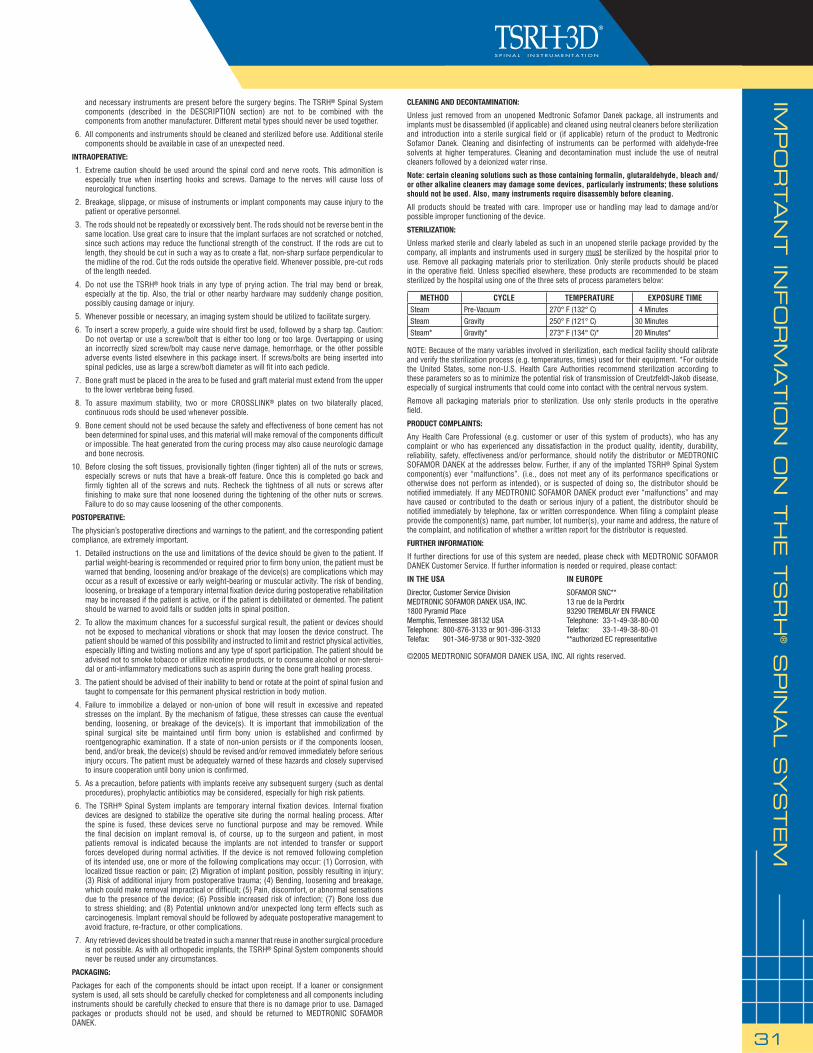
STERILIZATION:
Unless marked sterile and clearly labeled as such in an unopened sterile package provided by the company, all implants and instruments used in surgery must be sterilized by the hospital prior to use. Remove all packaging materials prior to sterilization. Only sterile products should be placed in the operative fi eld. Unless specifi ed elsewhere, these products are recommended to be steam sterilized by the hospital using one of the three sets of process parameters below:
NOTE: Because of the many variables involved in sterilization, each medical facility should calibrate and verify the sterilization process (e.g. temperatures, times) used for their equipment. *For outside the United States, some non-U.S. Health Care Authorities recommend sterilization according to these parameters so as to minimize the potential risk of transmission of Creutzfeldt-Jakob disease, especially of surgical instruments that could come into contact with the central nervous system.
Remove all packaging materials prior to sterilization. Use only sterile products in the operative fi eld.
PRODUCT COMPLAINTS:
Any Health Care Professional (e.g. customer or user of this system of products), who has any complaint or who has experienced any dissatisfaction in the product quality, identity, durability, reliability, safety, effectiveness and/or performance, should notify the distributor or MEDTRONIC SOFAMOR DANEK at the addresses below. Further, if any of the implanted TSRH® Spinal System component(s) ever “malfunctions”. (i.e., does not meet any of its performance specifi cations or otherwise does not perform as intended), or is suspected of doing so, the distributor should be notifi ed immediately. If any MEDTRONIC SOFAMOR DANEK product ever “malfunctions” and may have caused or contributed to the death or serious injury of a patient, the distributor should be notifi ed immediately by telephone, fax or written correspondence. When fi ling a complaint please provide the component(s) name, part number, lot number(s), your name and address, the nature of the complaint, and notifi cation of whether a written report for the distributor is requested.
FURTHER INFORMATION:
If further directions for use of this system are needed, please check with MEDTRONIC SOFAMOR DANEK Customer Service. If further information is needed or required, please contact:
IN THE USA IN EUROPE
Director, Customer Service Division SOFAMOR SNC**MEDTRONIC SOFAMOR DANEK USA, INC. 13 rue de la Perdrix1800 Pyramid Place 93290 TREMBLAY EN FRANCEMemphis, Tennessee 38132 USA Telephone: 33-1-49-38-80-00Telephone: 800-876-3133 or 901-396-3133 Telefax: 33-1-49-38-80-01Telefax: 901-346-9738 or 901-332-3920 **authorized EC representative
©2005 MEDTRONIC SOFAMOR DANEK USA, INC. All rights reserved.
METHOD CYCLE TEMPERATURE EXPOSURE TIMESteam Pre-Vacuum 270° F (132° C) 4 Minutes
Steam Gravity 250° F (121° C) 30 Minutes
Steam* Gravity* 273° F (134° C)* 20 Minutes*

NO
TES

LIT3DST5
For product availability and/or more information on any MEDTRONIC SOFAMOR DANEK USA, INC. products, contact your MEDTRONIC SOFAMOR DANEK USA, INC. Sales Associate, or call MEDTRONIC SOFAMOR DANEK USA, INC.
Customer Service toll free: 800-933-2635.
MEDTRONIC SOFAMOR DANEK USA, INC. 1800 Pyramid Place Memphis, TN 38132 (901) 396-3133 (800) 876-3133 Customer Service: (800) 933-2635
www.sofamordanek.comFor more information about this product visit www.myspinetools.com
©2005 Medtronic Sofamor Danek USA, Inc. All Rights Reserved. Patents Pending.