Embed Size (px)
Citation preview
TSTE19 Power Electronics
Lecture 1
Tomas Jonsson
ICS/ISY
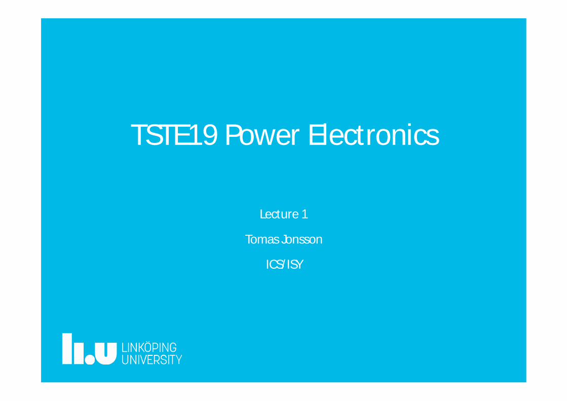
Tomas Jonsson• Education
– M. Sc. degree in Electrical Engineering from the Lund Institute ofTechnology, 1987
• Work Experience– Master thesis work at ABB HVDC Ludvika– ABB AB, Sweden since 1988.– HVDC control system design, Ludvika (1988 – 1992)– HVDC commissioning engineer, New Zealand HVDC project (1992-1993)– HVDC system development engineer, Ludvika (1993 – 1996)– HVDC system development manager, Ludvika (1997 – 1998)– Brazil-Argentina HVDC interconnection project (1998)– ABB Corporate Research HVDC & FACTS development projects, Västerås
(1999-2009)– ABB Grid Systems, R&D project manager, including mentoring of R&D
group in Chennai India– Since 2013, Senior Principal Engineer in the area of high power converters
for power transmission at ABB Grid Systems.
2004
-05-
05
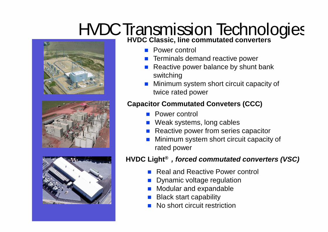
HVDC Transmission TechnologiesHVDC Classic, line commutated converters
HVDC Light® , forced commutated converters (VSC)
n Power controln Terminals demand reactive powern Reactive power balance by shunt bank
switchingn Minimum system short circuit capacity of
twice rated power
n Real and Reactive Power controln Dynamic voltage regulationn Modular and expandablen Black start capabilityn No short circuit restriction
Capacitor Commutated Conveters (CCC)n Power controln Weak systems, long cablesn Reactive power from series capacitorn Minimum system short circuit capacity of
rated power
© ABB Group
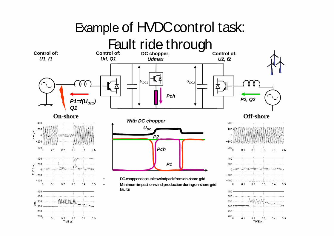
Example of HVDC control task:Fault ride through
P1=f(Udc1)Q1
uDC1 uDC2
P2, Q2
Control of:Ud, Q1
Control of:U2, f2
Control of:U1, f1
Pch
DC chopper:Udmax
With DC chopper
P2
P1
UDC
Pch
On-shore Off-shore
• DC-chopper decouples windpark from on-shore grid• Minimum impact on wind production during on-shore grid
faults
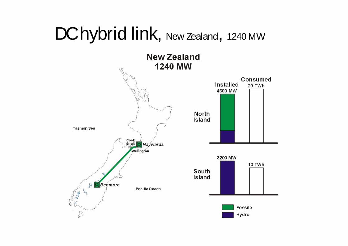
DC hybrid link, New Zealand, 1240 MW
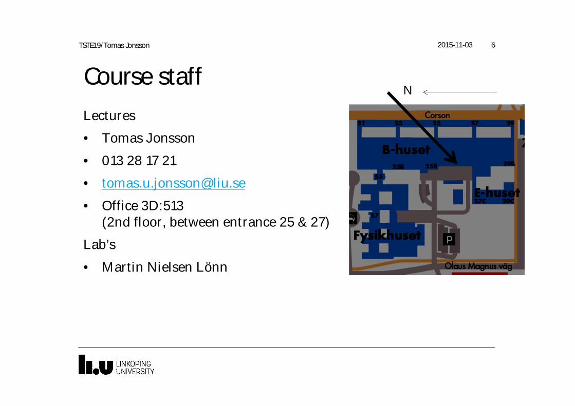
Course staffLectures
• Tomas Jonsson
• 013 28 17 21
• Office 3D:513(2nd floor, between entrance 25 & 27)
Lab’s
• Martin Nielsen Lönn
2015-11-03 6TSTE19/Tomas Jonsson
N
Course Contents• Course web page
http://www.isy.liu.se/edu/kurs/TSTE19/
• 16 Lectures (incl exercises)
– Introduce and explain material
– Problem solving
– Lab preparation
• 3 labs
– Lab 1 & 2: Multisim simulation of power circuits
– Lab 3: Control & measurements on power circuit
– Lab notes will be available on course web page
2015-11-03 7TSTE19/Tomas Jonsson
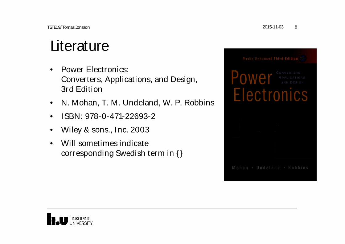
Literature• Power Electronics:
Converters, Applications, and Design,3rd Edition
• N. Mohan, T. M. Undeland, W. P. Robbins
• ISBN: 978-0-471-22693-2
• Wiley & sons., Inc. 2003
• Will sometimes indicatecorresponding Swedish term in {}
2015-11-03 8TSTE19/Tomas Jonsson
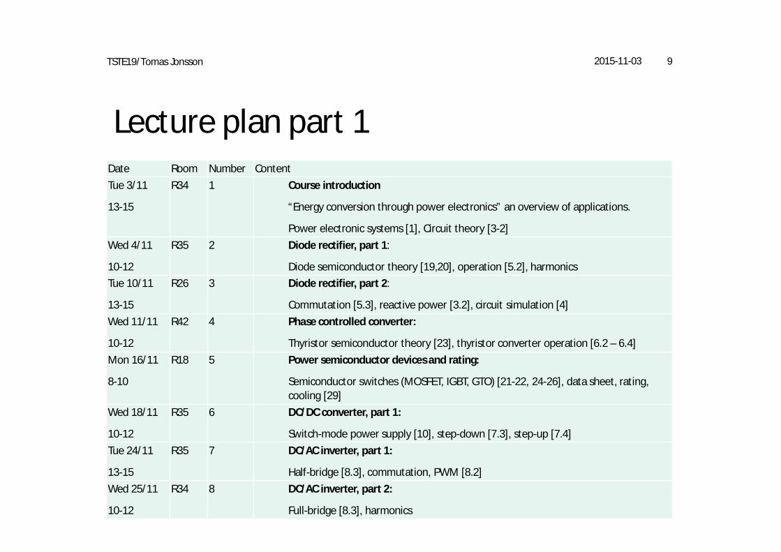
Lecture plan part 1
2015-11-03 9TSTE19/Tomas Jonsson
Date Room Number ContentTue 3/11
13-15
R34 1 Course introduction
“Energy conversion through power electronics” an overview of applications.
Power electronic systems [1], Circuit theory [3-2]Wed 4/11
10-12
R35 2 Diode rectifier, part 1:
Diode semiconductor theory [19,20], operation [5.2], harmonicsTue 10/11
13-15
R26 3 Diode rectifier, part 2:
Commutation [5.3], reactive power [3.2], circuit simulation [4]Wed 11/11
10-12
R42 4 Phase controlled converter:
Thyristor semiconductor theory [23], thyristor converter operation [6.2 – 6.4]Mon 16/11
8-10
R18 5 Power semiconductor devices and rating:
Semiconductor switches (MOSFET, IGBT, GTO) [21-22, 24-26], data sheet, rating,cooling [29]
Wed 18/11
10-12
R35 6 DC/DC converter, part 1:
Switch-mode power supply [10], step-down [7.3], step-up [7.4]Tue 24/11
13-15
R35 7 DC/AC inverter, part 1:
Half-bridge [8.3], commutation, PWM [8.2]Wed 25/11
10-12
R34 8 DC/AC inverter, part 2:
Full-bridge [8.3], harmonics
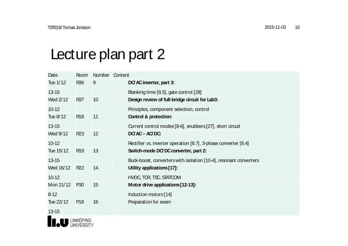
Lecture plan part 2
2015-11-03 10TSTE19/Tomas Jonsson
Date Room Number ContentTue 1/12
13-15
R36 9 DC/AC inverter, part 3:
Blanking time [8.5], gate control [28]Wed 2/12
10-12
R37 10 Design review of full-bridge circuit for Lab3:
Principles, component selection, controlTue 8/12
13-15
R18 11 Control & protection:
Current control modes [8-6], snubbers [27], short circuitWed 9/12
10-12
R23 12 DC/AC – AC/DC:
Rectifier vs. inverter operation [8.7], 3-phase converter [8.4]Tue 15/12
13-15
R19 13 Switch-mode DC/DC converter, part 2:
Buck-boost, converters with isolation [10-4], resonant convertersWed 16/12
10-12
R22 14 Utility applications [17]:
HVDC, TCR, TSC, STATCOMMon 21/12
8-12
P30 15 Motor drive applications [12-13]:
Induction motors [14]Tue 22/12
13-15
P18 16 Preparation for exam
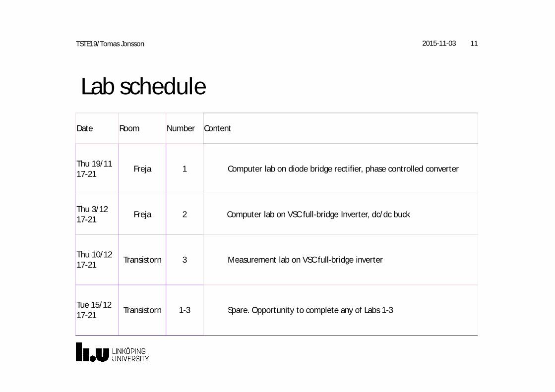
Lab schedule
2015-11-03 11TSTE19/Tomas Jonsson
Date Room Number Content
Thu 19/1117-21 Freja 1 Computer lab on diode bridge rectifier, phase controlled converter
Thu 3/1217-21 Freja 2 Computer lab on VSC full-bridge Inverter, dc/dc buck
Thu 10/1217-21 Transistorn 3 Measurement lab on VSC full-bridge inverter
Tue 15/1217-21 Transistorn 1-3 Spare. Opportunity to complete any of Labs 1-3
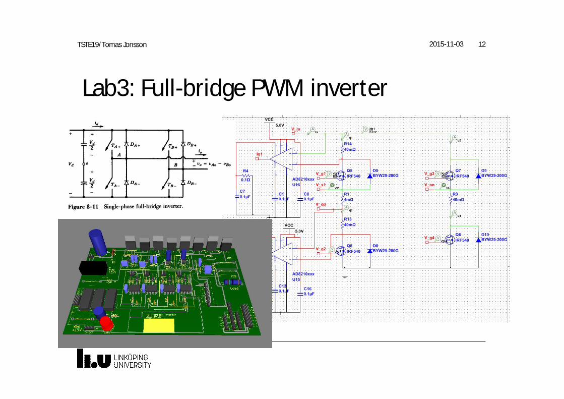
Lab3: Full-bridge PWM inverter
2015-11-03 12TSTE19/Tomas Jonsson
Examination• 3 Lab tasks completed and presented (during the lab)
– Simulation and measurement tasks
• Written exam
2015-11-03 13TSTE19/Tomas Jonsson
Lecture 1Power electronic systems from nW to GWPower electronic systems [Ch 1]Circuit theory [Ch 3-2]Exercises [1-1 – 1-5, 3-3 – 3-5]
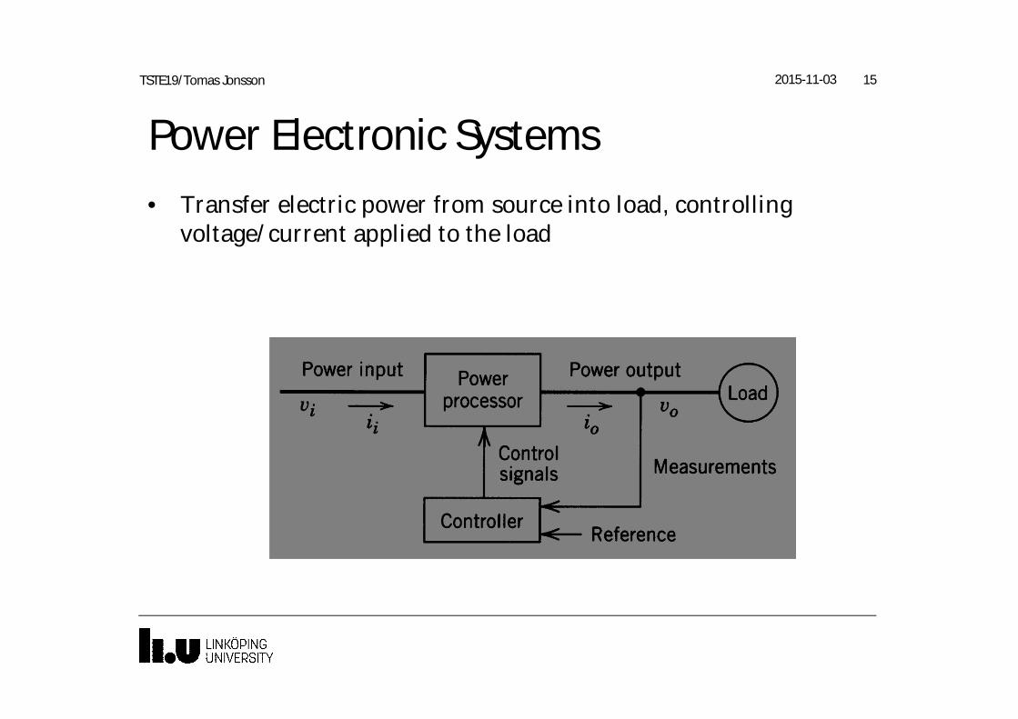
Power Electronic Systems• Transfer electric power from source into load, controlling
voltage/current applied to the load
2015-11-03 15TSTE19/Tomas Jonsson
Power electronic systems• Power conversion
– Frequency transformation, e.g. AC to DC, DC to AC
– Voltage level transformation, 230V to 12V
– Current control/limitation
– Power control, charging v.s. discharging
– Control related to load variations
– Control related to source variations
2015-11-03 16TSTE19/Tomas Jonsson
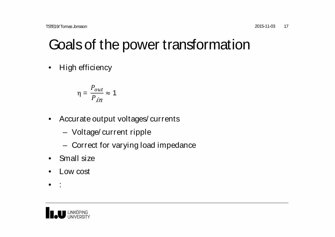
Goals of the power transformation• High efficiency
• Accurate output voltages/currents
– Voltage/current ripple
– Correct for varying load impedance
• Small size
• Low cost
• :
2015-11-03 17TSTE19/Tomas Jonsson
η = ≈ 1
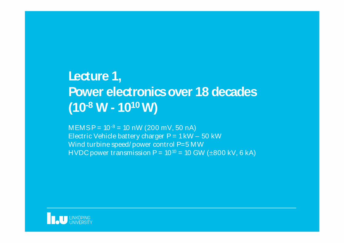
Lecture 1,Power electronics over 18 decades(10-8 W - 1010 W)MEMS P = 10-8 = 10 nW (200 mV, 50 nA)Electric Vehicle battery charger P = 1 kW – 50 kWWind turbine speed/power control P=5 MWHVDC power transmission P = 1010 = 10 GW (±800 kV, 6 kA)
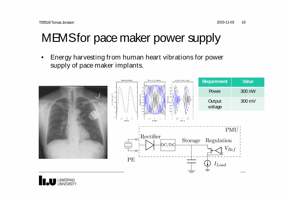
MEMS for pace maker power supply• Energy harvesting from human heart vibrations for power
supply of pace maker implants.
2015-11-03 19TSTE19/Tomas Jonsson
Requirement Value
Power 300 nW
Outputvoltage
300 mV
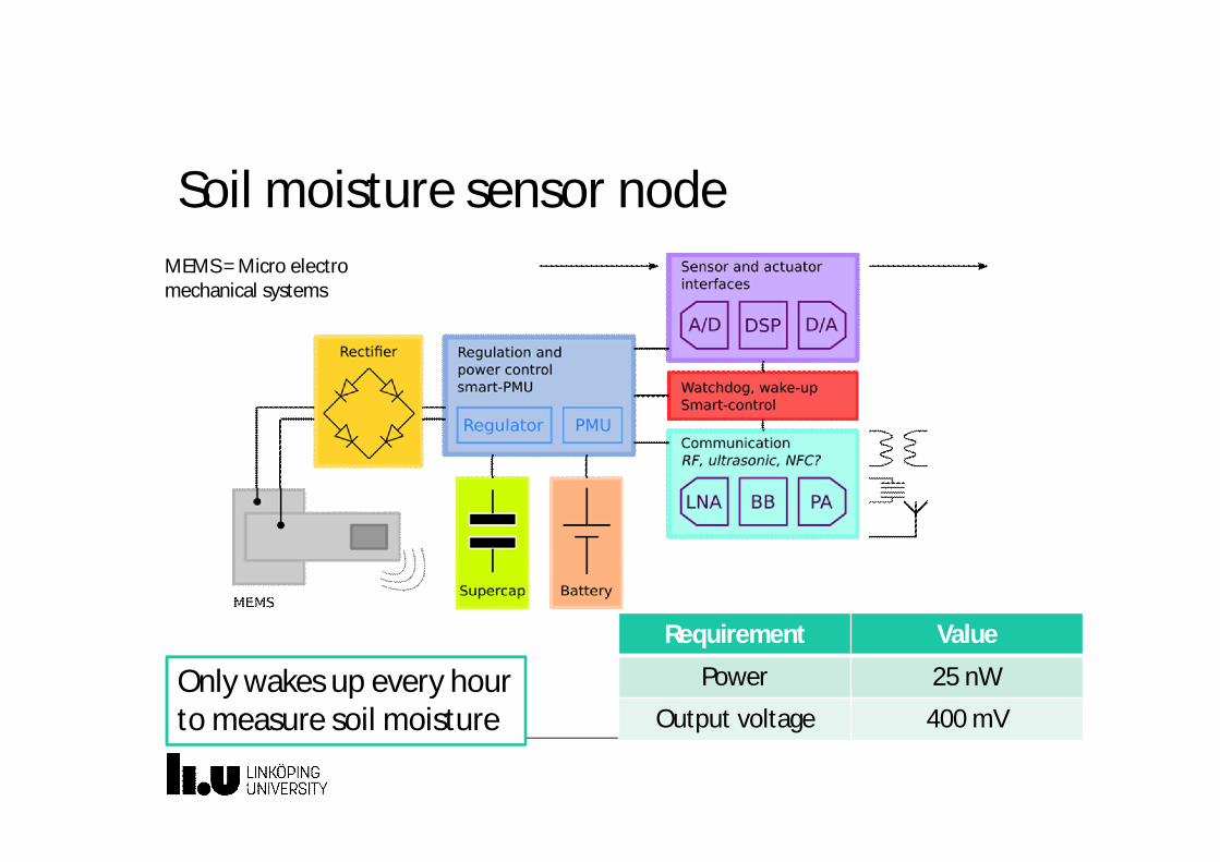
Soil moisture sensor node
Requirement Value
Power 25 nW
Output voltage 400 mVOnly wakes up every hourto measure soil moisture
MEMS = Micro electromechanical systems
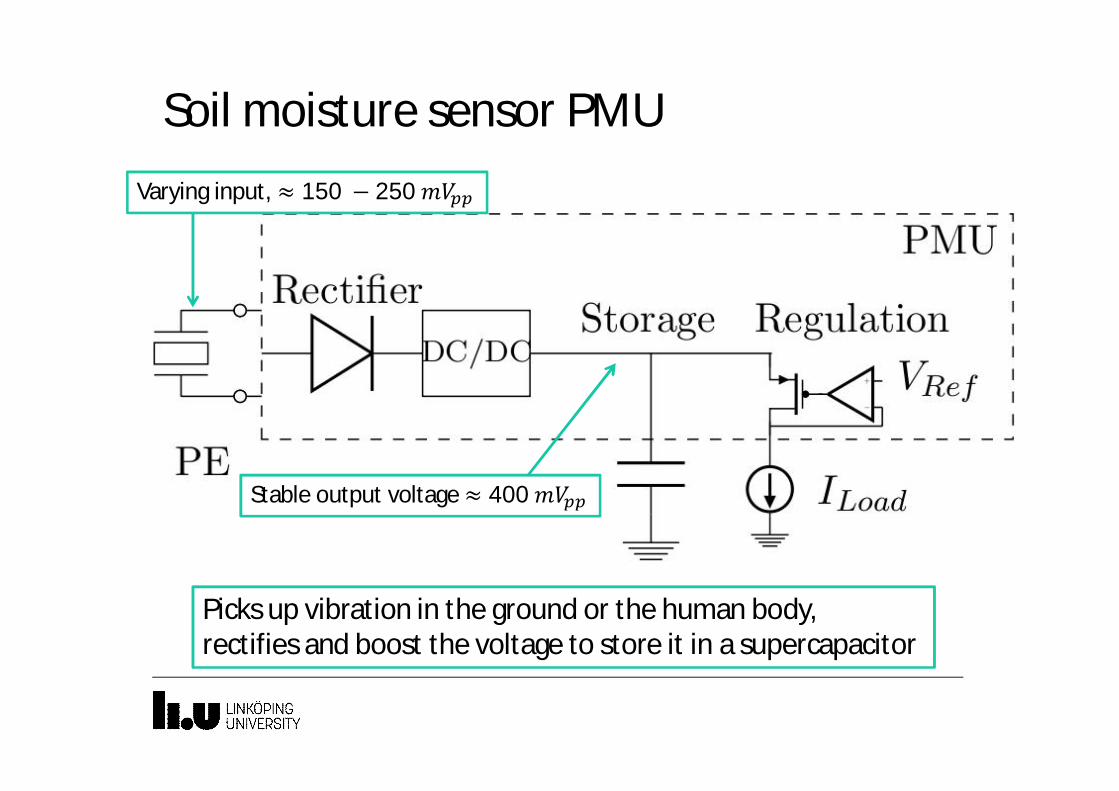
Soil moisture sensor PMU
Picks up vibration in the ground or the human body,rectifies and boost the voltage to store it in a supercapacitor
Varying input, ≈ 150 − 250
Stable output voltage ≈ 400
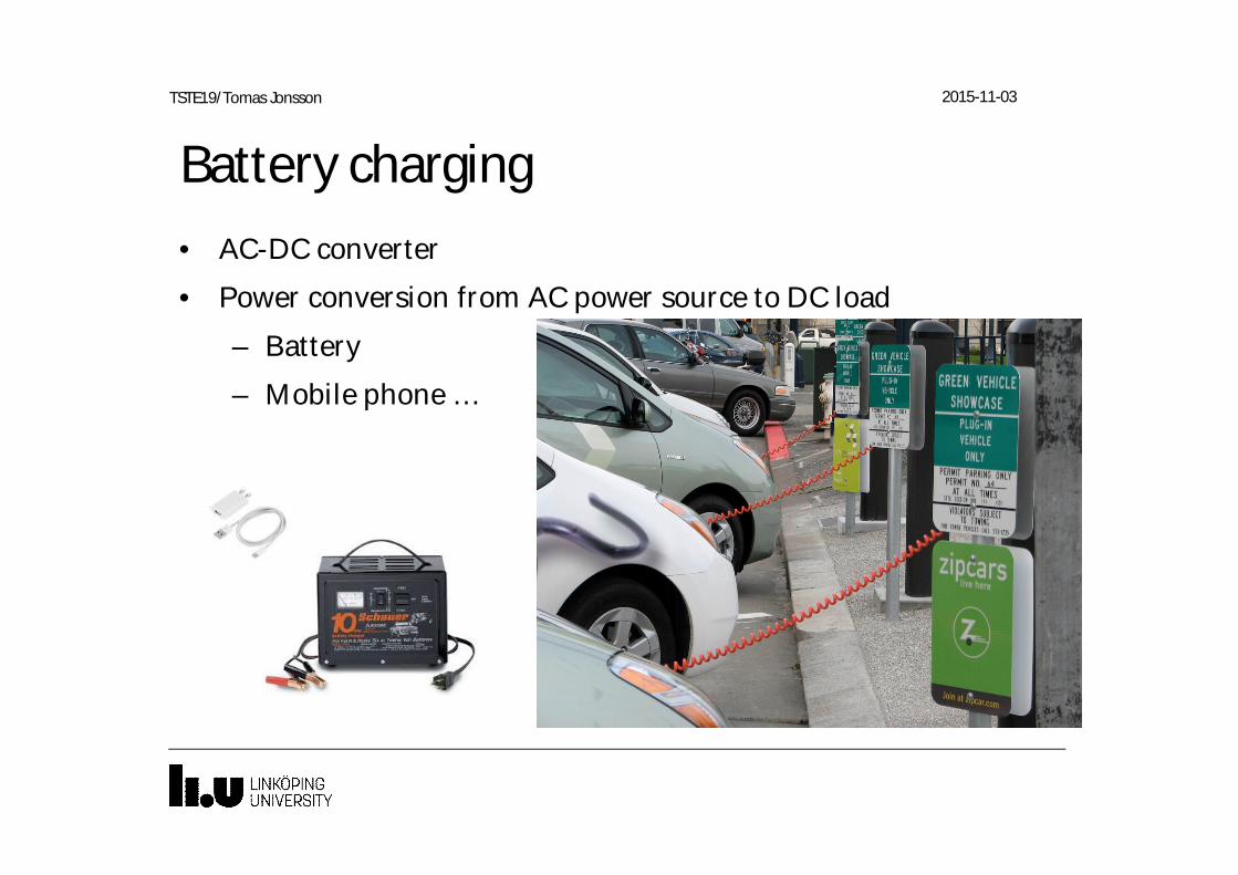
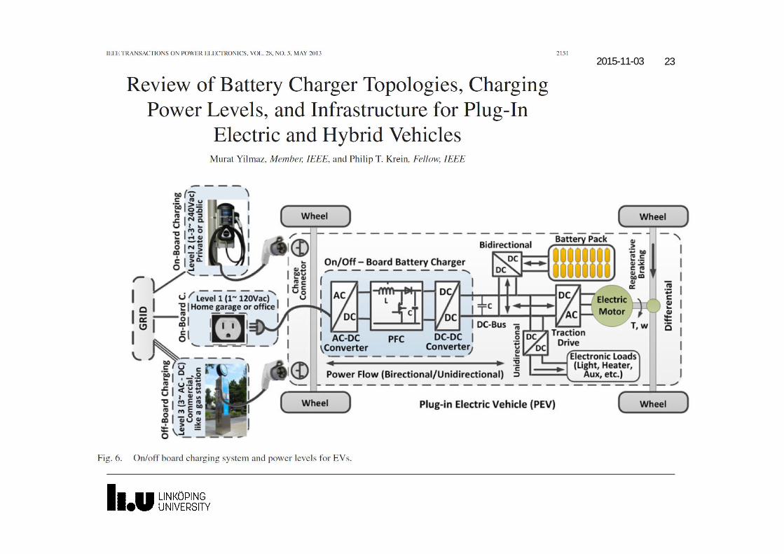
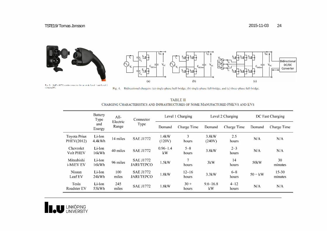
Battery charging• AC-DC converter
• Power conversion from AC power source to DC load
– Battery
– Mobile phone …
TSTE19/Tomas Jonsson 2015-11-03
2015-11-03 23TSTE19/Tomas Jonsson
2015-11-03 24TSTE19/Tomas Jonsson
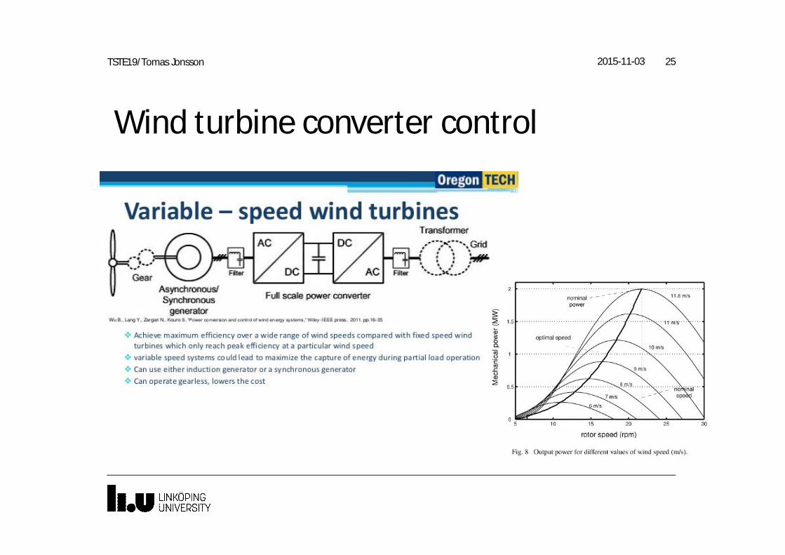
Wind turbine converter control
2015-11-03 25TSTE19/Tomas Jonsson
Lecture 1, Power electronics of20 decades (10-10 W - 1010 W)HVDC
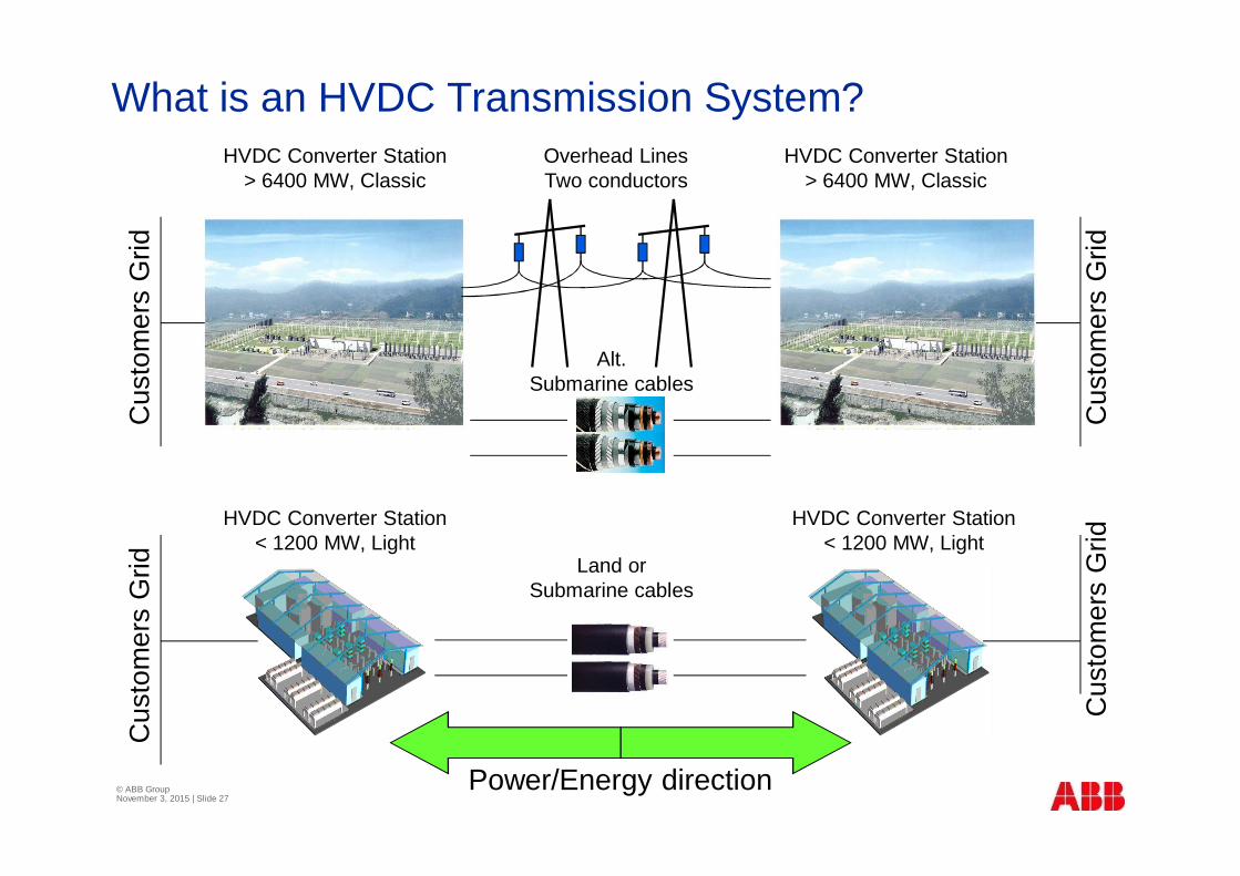
What is an HVDC Transmission System?
Hydro
Solar
Hydro
Solar
HVDC Converter Station> 6400 MW, Classic
HVDC Converter Station< 1200 MW, Light
HVDC Converter Station> 6400 MW, Classic
HVDC Converter Station< 1200 MW, Light
Power/Energy direction
Cus
tom
ers
Grid
Cus
tom
ers
Grid
Cus
tom
ers
Grid
Cus
tom
ers
Grid
Overhead LinesTwo conductors
Alt.Submarine cables
Land orSubmarine cables
© ABB GroupNovember 3, 2015 | Slide 27
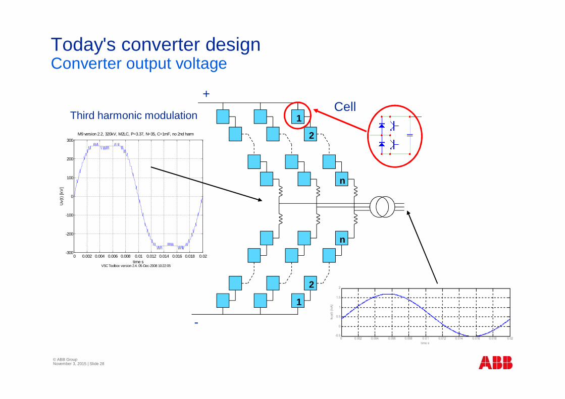
Today's converter designConverter output voltage
1
2
n
1
2
n
Cell+
-
0 0.002 0.004 0.006 0.008 0.01 0.012 0.014 0.016 0.018 0.02-300
-200
-100
0
100
200
300M9 version 2.2, 320kV, M2LC, P=3.37, N=35, C=1mF, no 2nd harm
VSC Toolbox version 2.4. 05-Dec-2008 10:22:05
Uv(
t)[k
V]
time s
Third harmonic modulation
© ABB GroupNovember 3, 2015 | Slide 28
© ABB GroupNovember 3, 2015 | Slide 29
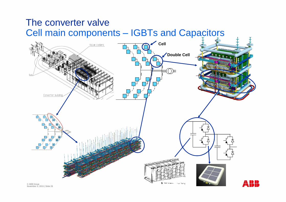
The converter valveCell main components – IGBTs and Capacitors
Cell
Double Cell
© ABB GroupNovember 3, 2015 | Slide 30
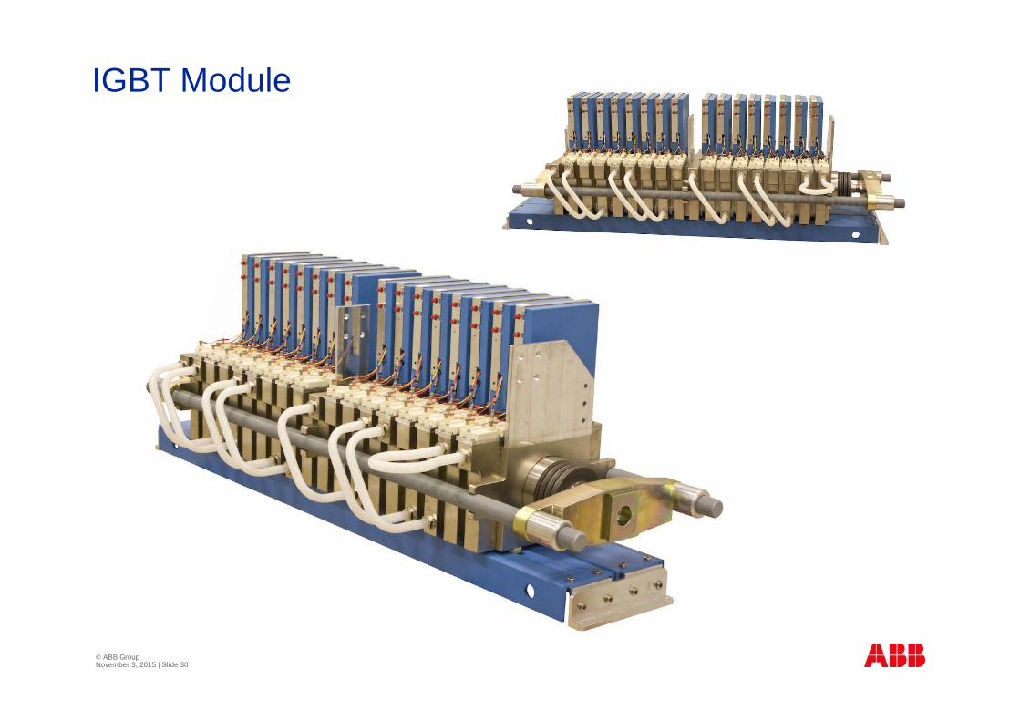
IGBT Module
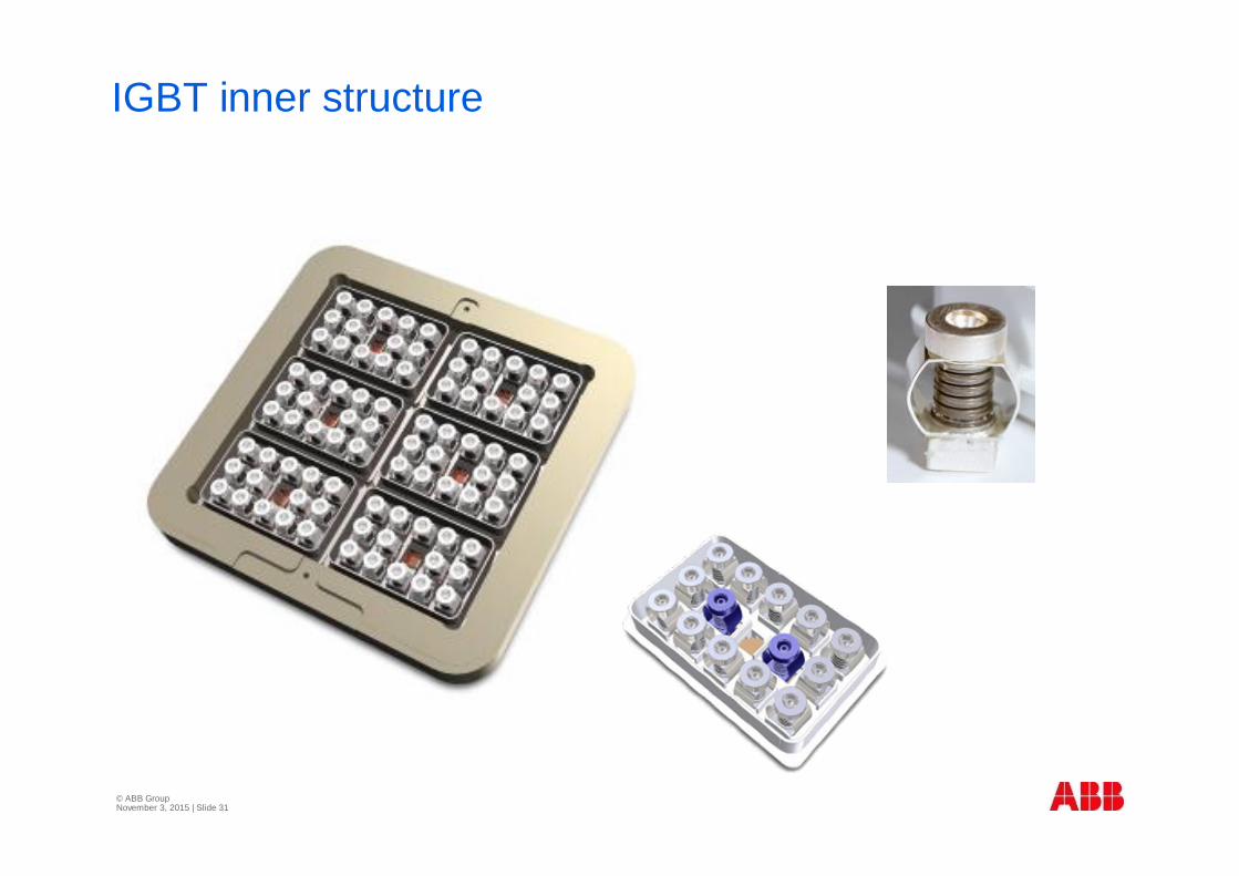
© ABB GroupNovember 3, 2015 | Slide 31
IGBT inner structure
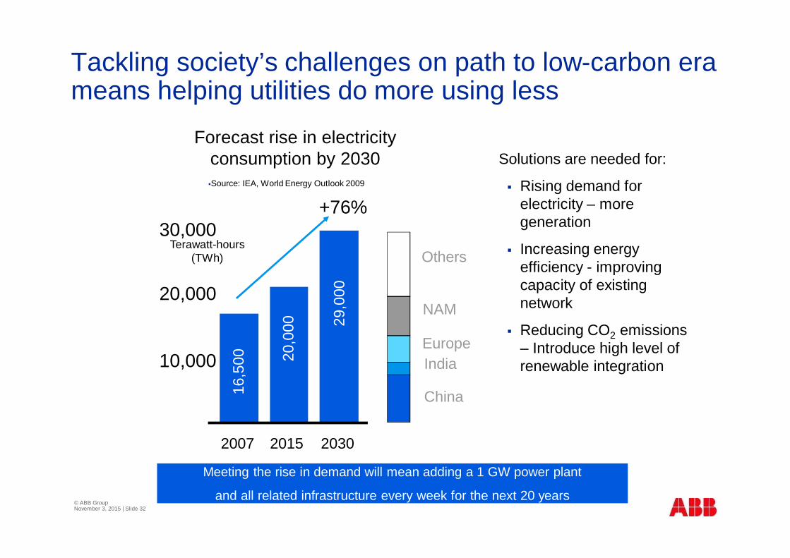
Tackling society’s challenges on path to low-carbon erameans helping utilities do more using less
§Source: IEA, World Energy Outlook 2009
12,5
00
Terawatt-hours(TWh)
10,000
20,000
30,00016
,500
2007 2015 2030
20,0
00 29,0
00
+76%
Solutions are needed for:
§ Rising demand forelectricity – moregeneration
§ Increasing energyefficiency - improvingcapacity of existingnetwork
§ Reducing CO2 emissions– Introduce high level ofrenewable integration
Forecast rise in electricityconsumption by 2030
Others
NAM
EuropeIndia
China
Meeting the rise in demand will mean adding a 1 GW power plant
and all related infrastructure every week for the next 20 years© ABB GroupNovember 3, 2015 | Slide 32
IEA World Energy Outlook 2012 - 2035
§ 5 890 GW of capacity additions (> the total installedcapacity in 2011) is required
§ One-third of this is to replace retiring plants; the rest is to meetgrowing electricity demand.
§ Renewables represent half : 3000 GW. Gas 1400 GW.
§ The power sector requires investment of $16.9 trillion,
§ Investment in generation capacity, > 60% is for renewables:wind (22%), hydro (16%), solar PV (13%).
© ABB GroupNovember 3, 2015 | Slide 33
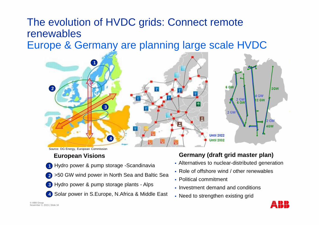
Source: DG Energy, European Commission
§1
§2
§3
§4
Hydro power & pump storage -Scandinavia
>50 GW wind power in North Sea and Baltic Sea
Hydro power & pump storage plants - Alps
Solar power in S.Europe, N.Africa & Middle East
§1
§2
§31§4
§ Alternatives to nuclear-distributed generation§ Role of offshore wind / other renewables§ Political commitment§ Investment demand and conditions§ Need to strengthen existing grid
The evolution of HVDC grids: Connect remoterenewablesEurope & Germany are planning large scale HVDC
European Visions Germany (draft grid master plan)
© ABB GroupNovember 3, 2015 | Slide 34
Lecture 1Power electronic systems {Ch1}Power basicsCircuit theory
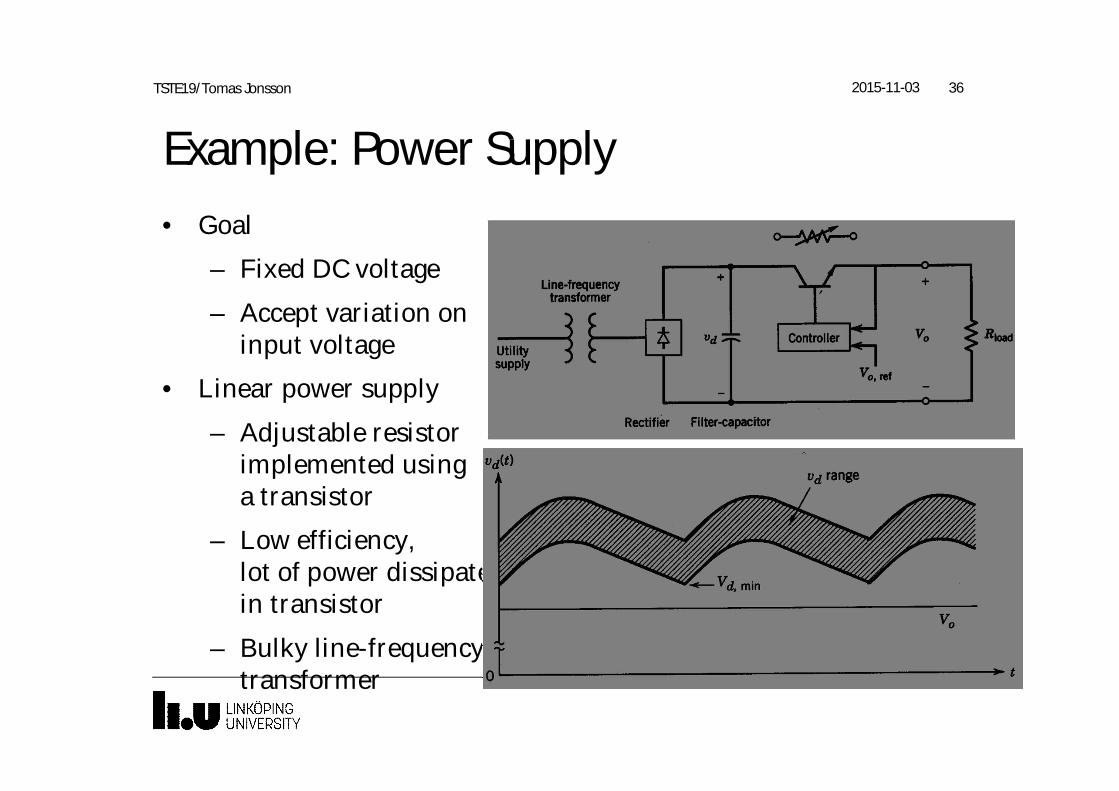
Example: Power Supply• Goal
– Fixed DC voltage
– Accept variation oninput voltage
• Linear power supply
– Adjustable resistorimplemented usinga transistor
– Low efficiency,lot of power dissipatedin transistor
– Bulky line-frequencytransformer
2015-11-03 36TSTE19/Tomas Jonsson
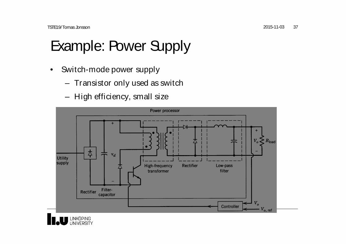
Example: Power Supply• Switch-mode power supply
– Transistor only used as switch
– High efficiency, small size
2015-11-03 37TSTE19/Tomas Jonsson
Goal of power conversion• Translate input voltage into expected waveform of output
voltage
• Dissipate little/no power
• Technology: semiconductors, inductors, capacitors, (resistors)
• Should not use semiconductors as resistances
2015-11-03 38TSTE19/Tomas Jonsson
Symbol definitions• uab, Uab Voltage. Uab is the voltage between points a and b.
• va Potential. The voltage to ground at point a.
• OBS, the course book uses american standard:v for voltages in general.
• ia, Ia Current in path (phase) a.
• pa, Pa Power. Active power
• Lower case symbols denotes instantaneous values
• Upper case symbols denotes average or RMS values
2015-11-03 39TSTE19/Tomas Jonsson
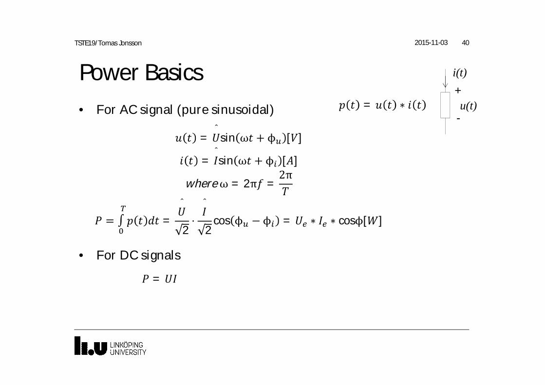
Power Basics• For AC signal (pure sinusoidal)
• For DC signals
2015-11-03 40TSTE19/Tomas Jonsson
= ∗
i(t)+
-u(t)
=
=ˆ
sin ω + ϕ [ ]
=ˆsin ω + ϕ [ ]
whereω = 2π =2π
= ∫ =
ˆ
2⋅
ˆ
2cos ϕ −ϕ = ∗ ∗ cosϕ[ ]
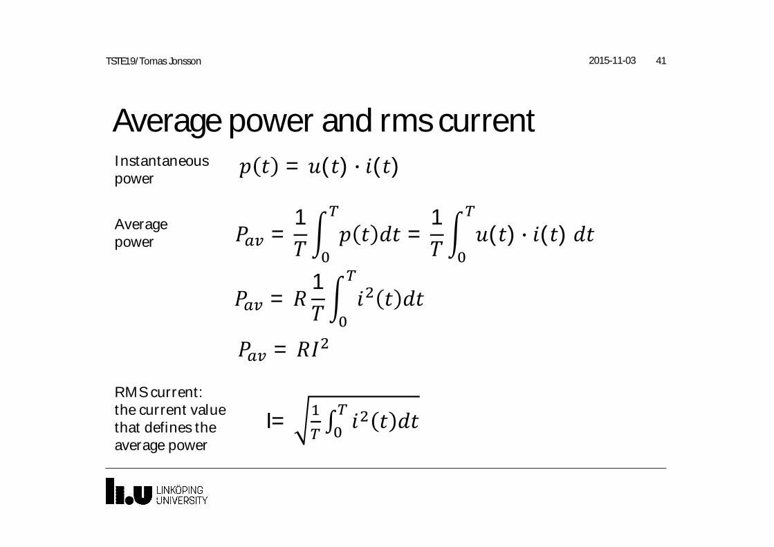
Average power and rms current
2015-11-03 41TSTE19/Tomas Jonsson
= ( ) ( )
=1
=1
( ) ( )
=1
=
I= ∫
Instantaneouspower
Averagepower
RMS current:the current valuethat defines theaverage power
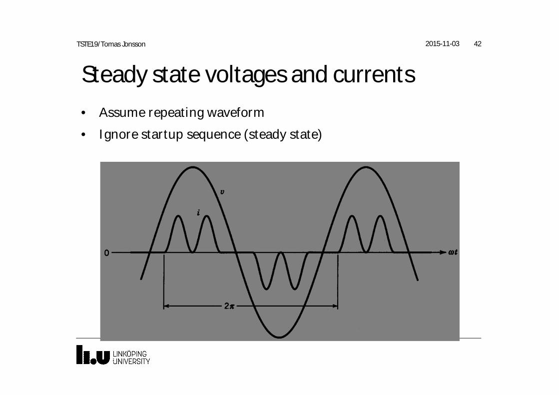
Steady state voltages and currents• Assume repeating waveform
• Ignore startup sequence (steady state)
2015-11-03 42TSTE19/Tomas Jonsson

Fourier analysis
2015-11-03 43TSTE19/Tomas Jonsson
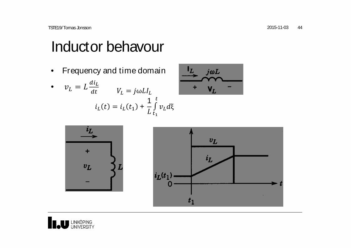
Inductor behavour• Frequency and time domain
• =
2015-11-03 44TSTE19/Tomas Jonsson
= ω
= +1∫ ξ
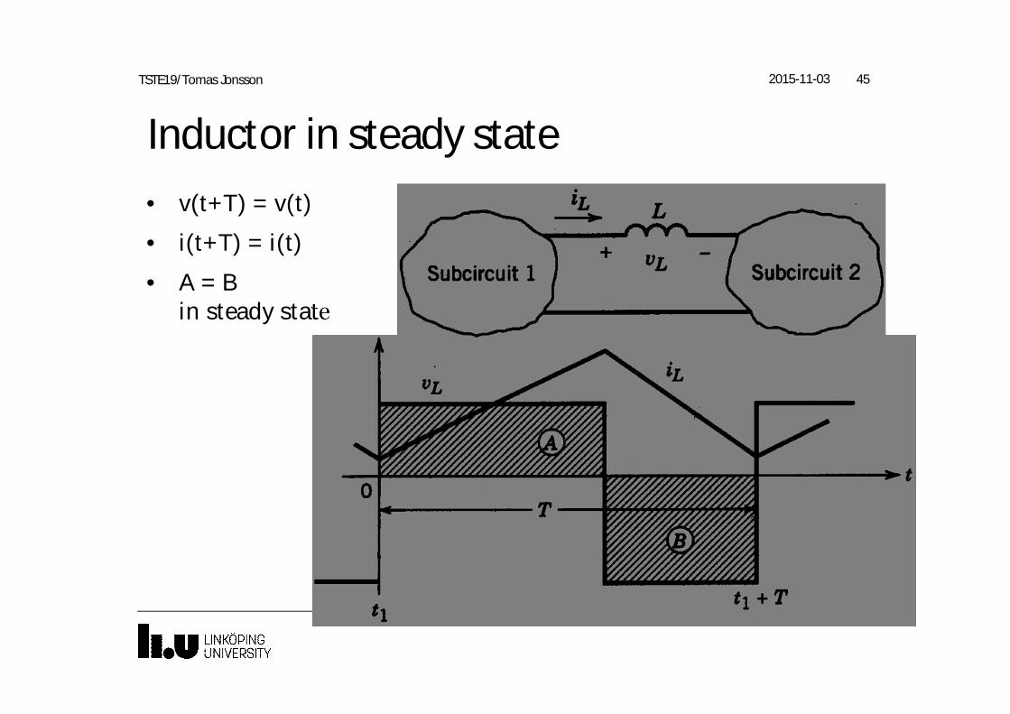
Inductor in steady state• v(t+T) = v(t)
• i(t+T) = i(t)
• A = Bin steady state
2015-11-03 45TSTE19/Tomas Jonsson
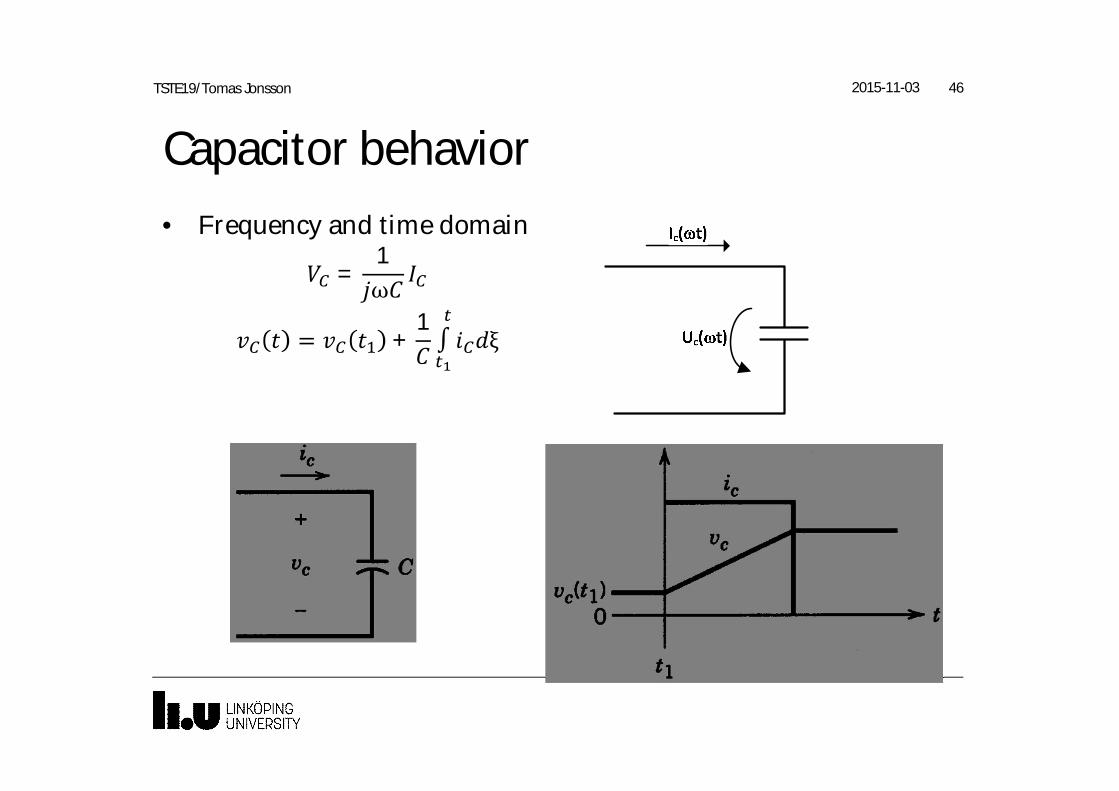
Capacitor behavior• Frequency and time domain
2015-11-03 46TSTE19/Tomas Jonsson
=1ω
= +1∫ ξ
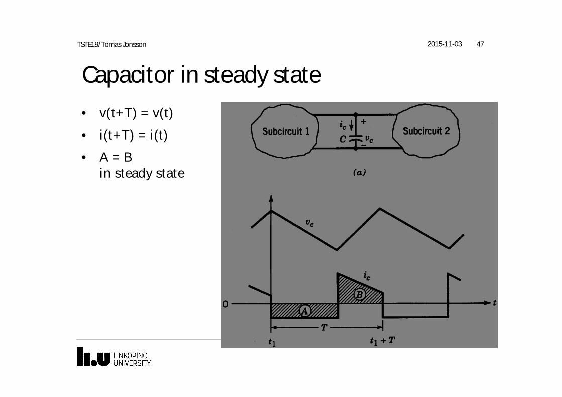
Capacitor in steady state• v(t+T) = v(t)
• i(t+T) = i(t)
• A = Bin steady state
2015-11-03 47TSTE19/Tomas Jonsson
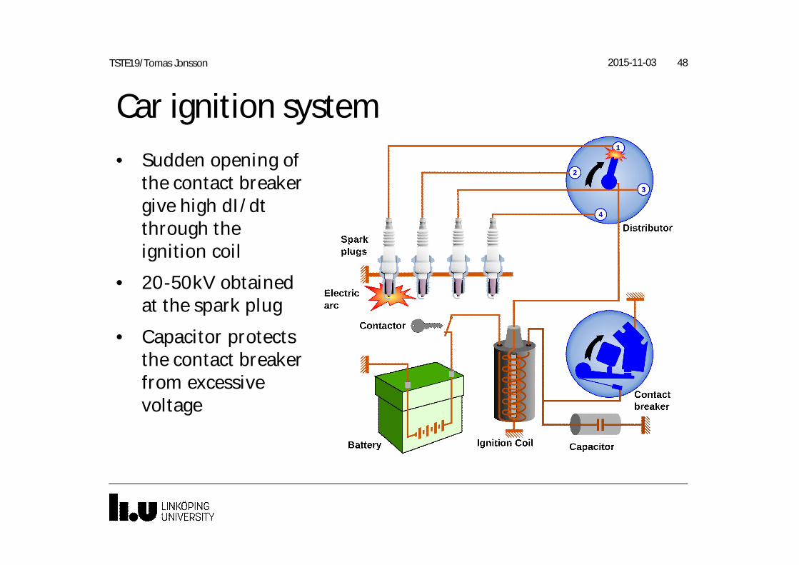
Car ignition system• Sudden opening of
the contact breakergive high dI/dtthrough theignition coil
• 20-50kV obtainedat the spark plug
• Capacitor protectsthe contact breakerfrom excessivevoltage
2015-11-03 48TSTE19/Tomas Jonsson
Exercises, lecture 11-1, 1-2, 1-3, 1-4, 1-53-3, 3-4, 3-5
2015-11-0349TSTE19/Tomas Jonsson
2015-11-03 50TSTE19/Tomas Jonsson
2015-11-03 51TSTE19/Tomas Jonsson
2015-11-03 52TSTE19/Tomas Jonsson
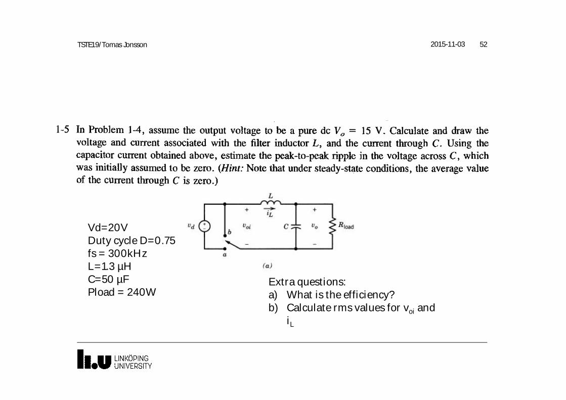
Vd=20VDuty cycle D=0.75fs = 300kHzL=1.3 µHC=50 µFPload = 240W
Extra questions:a) What is the efficiency?b) Calculate rms values for voi and
iL

2015-11-03 53TSTE19/Tomas Jonsson
Vd=20VDuty cycle D=0.75fs = 300kHzL=1.3 µHC=50 µFPload = 240W
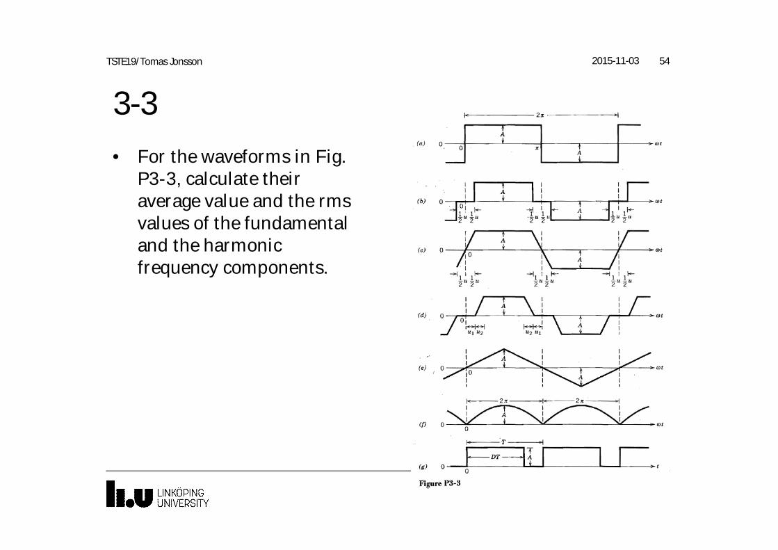
3-3• For the waveforms in Fig.
P3-3, calculate theiraverage value and the rmsvalues of the fundamentaland the harmonicfrequency components.
2015-11-03 54TSTE19/Tomas Jonsson
3-4In the waveforms of Fig. P3-3 of Problem 3-3, A = 10 and u = 20°(ul = U2 = u/2) , where applicable. Calculate their total rms valuesas follows:
a) By using the results of Problem 3-3 in Eq. 3-28.
b) By using the definition of the rms value as given in Eq. 3-5.
2015-11-03 55TSTE19/Tomas Jonsson
3-5Refer to Problem 3-4 and calculate the following:
a) For each of the waveforms a-e, calculate
i. the ratio of the fundamental frequency component to thetotal rms value
ii. the ratio of the distortion component to the total rmsvalue.
b) For the waveforms f and g, calculate the ratio of the averagevalue to the total rms value.
2015-11-03 56TSTE19/Tomas Jonsson