Embed Size (px)
Citation preview

Tsunami Inundation Scour of Roadways, Bridges and Foundations Observations and Technical Guidance from the Great Sumatra Andaman Tsunami
EERI / FEMA NEHRP 2006 Professional Fellowship Report

E E R I / F E M A N E H R P 2 0 0 6 P R O F E S S I O N A L F E L L O W S H I P R E P O R T
Tsunami Inundation Scour of Roadways, Bridges and Foundations Observations and Technical Guidance from the Great Sumatra Andaman Tsunami Mathew J. Francis, P.E. Principal Advisor: Harry Yeh Oregon State University About The Cover Upper photo: Sumatra tsunami hitting Koh Pu, Thailand, copyright Anders Grawin. Lower left photo: Sumatra tsunami overtopping waterfront roadway, Tap Lamu, Thailand, ref. Absorsuda Siripong, Chulalongkorn University. Lower right photo: Coastal roadway erosion from the Sumatra tsunami, Nicobar Islands, India, courtesy United Sikhs of Nicobar.
www.eeri.org
2006 EERI / FEMA NEHRP Professional Fellowship Report

FINAL DRAFT
ii EERI / FEMA NEHRP 2006 PROFESSIONAL FELLOWSHIP REPORT TSUNAMI SCOUR
TABLE OF CONTENTS
EXECUTIVE SUMMARY........................................................................................................ 1
1.0 INTRODUCTION AND OVERVIEW............................................................................ 2
2.0 SCOUR METHODS .................................................................................................... 2 2.1 Types of Scour ................................................................................................. 2 2.2 River Scour ...................................................................................................... 3 2.3 Tidal Scour ....................................................................................................... 5 2.4 Seafloor Scour ................................................................................................. 5 2.5 Tsunami Scour – FEMA Method...................................................................... 6 2.6 Enhanced Tsunami Scour – Yeh & Tonkin Method ......................................... 8 2.7 Liquefaction Considerations............................................................................. 9 2.8 Scour Method Comparison ............................................................................ 10 2.9 Integrated Scour Theory ................................................................................ 11 3.0 TSUNAMI SCOUR OBSERVATIONS ...................................................................... 11 3.1 Field Survey Observations............................................................................. 12 3.2 Photographic Literature Review..................................................................... 13 3.3 Scour Comparisons from Banda Aceh and Lhoknga, Sumatra, Indonesia........................................................................................................ 13
4.0 TSUNAMI SCOUR EVALUATION............................................................................ 16 4.1 Site Parameters ............................................................................................. 16 4.2 Tide Data Parameters .................................................................................... 16 4.3 Scour Calculations and Findings ................................................................... 16
5.0 CONCLUSIONS........................................................................................................ 18
REFERENCES .................................................................................................................... 21

FINAL DRAFT
iii EERI / FEMA NEHRP 2006 PROFESSIONAL FELLOWSHIP REPORT TSUNAMI SCOUR
FIGURES Figure 1. Study Area Figure 2. Hjulstrom’s diagram Figure 3. Pier scour depth vs. exposure duration in a sand-bed stream Figure 4. SRICOS scour data comparison, critical shear stress vs. soil particle size Figure 5. Estuary, after Neill 1973 Figure 6. Time lag of tidal scour: ratio of scour depth to maximum scour depth vs. time Figure 7. Equilibrium tidal scour depth vs. flow velocity Figure 8. Liquefaction caused by wave Figure 9. Particle lift and drag trajectory during one wave cycle Figure 10. Seaward impact loading induced by wave overtopping Figure 11. Tsunami velocity criteria vs. scour depth Figure 12. Measured scour depth and estimated Shields parameter for a cylinder initially at the shoreline
during long period wave modeling. Water depth=2.45m, offshore incident solitary-wave height H=33cm. H/h=0.09
Figure 13. Seafloor liquefaction mitigation concept Figure 14. Tsunami inundations in Thailand Figure 15. Seafloor boulder, sorted debris, and scoured sump, Thailand Figure 16. Inundation patterns at Banda Aceh and Lhoknga, Sumatra Figure 17. Ground shaking intensity map of Banda Aceh Figure 18. Map of liquefaction (blue) and ground fracture (red) in Banda Aceh Figure 19. Liquefaction sand boils from the great tsunami, northwest coast of Sumatra Figure 20. Scour depth vs. shoreline setback ratio Figure 21. Yeh and Tonkin method lamda vs. wave height to period ratios, 20 sites denoting hypothesized
liquefaction threshold of 0.5 TABLES Table 1. Relative Conceptual Comparison of Scour Hazards Table 2. Tsunami Design Criteria Table 3. Scour Comparison Criteria Table 4. Summary Comparison of Selected Scour Methods Table 5. Generalized Observed Tsunami Inundation Table 6. Summary of Transported Sediment and Debris APPENDICES A. Tsunami Scour Evaluation Site Photos B. Tsunami Scour Evaluation Data Tables B1-B3 C. Tide Gage Records D. General Tsunami Scour Photos

FINAL DRAFT
1 EERI / FEMA NEHRP 2006 PROFESSIONAL FELLOWSHIP REPORT TSUNAMI SCOUR
EXECUTIVE SUMMARY The December 26, 2004 great Andaman Sumatra tsunami wreaked havoc across the Indian Ocean, as beaches transformed to scenes of destruction and watery graves for more than 230,000 residents and tourists. The study and research of this multi-faceted hazard continues with renewed commitment and soberness. This Earthquake Engineering Research Institute (EERI) fellowship granted under the National Earthquake Hazard Reduction (NEHRP) by the Federal Emergency Management Agency (FEMA) investigates evidence of scour damage from the great tsunami, focusing upon site observations and their reflections upon current scour theory. Basic distinctions of criteria are presented between well established scour methods, such as river and tidal scour and two tsunami scour evaluation methods (Coastal Construction Manual by FEMA and Liquefaction Enhanced Scour by Yeh and Tonkin). Limitations of liquefaction evaluations for seismic, and seafloor wave liquefaction are also discussed. An evaluation of scour depth and runup inundation conditions is presented for 20 road and building sites selected from among thousands of photographs reviewed. Observed runup heights and scour depths at the selected sites were used with nearest available tide gage records to model drawdown conditions at the sites for estimating potential pore pressure conditions. The potential for liquefaction enhancement of tsunami scour is widely validated among the range of selected sites using the Yeh and Tonkin method. Results are presented in tables corresponding site photographs. Contradictions remain from the tsunami scour observations and analysis. Most notable is the rarity of scour depths greater than two meters among a broad range of flow depths and site conditions. A general trend of observed tsunami scour was at locations within the beachfront half of inundation distances, again regardless of flow depth. Correlation of scour severity by topography, vegetation and soil type (i.e., gradation and amount of fines) is also uncertain. Significant research needs remain in the evolving multidisciplinary field of tsunami engineering, such as advanced soil-fluid-structure interaction modeling to develop a unified tsunami scour theory that accounts for many uncertainties that squarely straddle the practices of tsunami hydrodynamics and geomechanics.

FINAL DRAFT
2 EERI / FEMA NEHRP 2006 PROFESSIONAL FELLOWSHIP REPORT TSUNAMI SCOUR
Figure 1. Study Area (GEBCO, 2005; Bathym, ETOPO-2).
1.0 INTRODUCTION AND OVERVIEW This report of research for the 2006 EERI / FEMA NEHRP 2006 Professional Fellowship focuses upon tsunami scour in response to the staggering human loss, suffering and damage caused by the Great Sumatra Andaman Tsunami and Earthquake of 26 December 2004. The broad reach of damaging event waves were observed and photographed widely, producing unprecedented data as a basis for research and technological develop for many years to come (ref EERI, 2006). Sparseness of previous research in tsunami scour contrasts with the vast damage, providing opportunity to compare current knowledge with field conditions. An observational approach will help provide an empirical frame of reference to aid future more theoretical studies. Reported findings are also intended to provide researchers and decision makers with information and technical guidance that can reduce future tsunami damage. Tsunamis are complex natural hazards involving multi-disciplinary processes. This tsunami scour study draws upon three broad arenas of ocean engineering, geotechnical engineering and applied hydraulics, with applications in geo-mechanics, poro-mechanics, hydro-dynamics and sedimentation. The core of the report is a progressive consideration of fundamental components of tsunami scour theory derived from related fields of applied scour theories. A broad range of field observations are discussed from sites in India, Nicobar, Thailand, Sumatra, and Somalia (Fig 1). Available runup data and tide gage data is presented with an evaluation of tsunami scour for observed runup and soil conditions at 20 sites among the broad reach of damage from the great tsunami. Interdisciplinary aspects are considered with scour conclusions and a summary of issues for further research to develop more reliable design procedures and codes. Perspective for an integrated scour theory is deduced from this review, for consideration by future studies and observations of tsunami scour. 2.0 SCOUR METHODS 2.1 Types of Scour Tsunami scour theory relies upon physical interactions between water, soil and structures, similar to other scour though, being long period waves (ref. Yeh, 1997), in a vastly different relation of time, space, and magnitude (Table 1). This phenomenon rapidly and efficiently transmits large amounts of seismic energy, ripping apart coastal zones of the earth and producing thorough destruction at runup heights of even less than 2m. In organizing observations of tsunami scour, one acknowledges many factors affecting actual runup conditions, energy distributions, and damage patterns. So while the role of scour in a tsunami event needs to be weighed and validated with other mechanisms of site damage, observed conditions and patterns of tsunami scour can be compared with existing scour theories to help provide perspective to the content and balance of tsunami damages as a whole. Thus this study seeks to examine positive scour evidence before exploring less certain conditions, such as why scour may not have occurred elsewhere and how

FINAL DRAFT
3 EERI / FEMA NEHRP 2006 PROFESSIONAL FELLOWSHIP REPORT TSUNAMI SCOUR
Table 1. Relative Conceptual Comparison of Scour Hazards, adapted from Yeh et al., 2003
Figure 2. Hjulstrom’s diagram (Pinet, 2003).
Scour Hazard Wave
Period Area of Stress Cycles
Event Duration (ΔT)
Fluid Pressure Change (ΔP)
Relative Porewater Gradient (ΔP/ΔT)
Possible Energy Intensity
River seasonal n/a seasonal variable Low Variable
Flood days n/a < 3 weeks <10m Medium Very high
Ocean Wave <1min small < 3 days <10m High High
Tsunami >10min large <3 hours <10m Extreme Extreme
Earthquake <1sec large <3 minutes porewater Very high Extreme
scour relates to overall tsunami damage. Since scour depth provides a reasonably uniform basis for determining potential damaging consequences, a review of various current scour depth methods provides for simplified comparisons with tsunami scour. Current scour depth methods include several older, now standard and widely used procedures developed for scours in riverbed and tidal environments, with some newer supplements to more specific soil or structure conditions, plus more specialized methodologies for offshore practices. A handful of these methods will be compared with two existing simplified methods of estimating tsunami scour depths, and then effects of tsunami induced soil liquefaction will be discussed based upon liquefaction studies from earthquake and ocean wave events. Sections 3 to 6 present gathered site data and results using existing tsunami scour depth methods to evaluate scour and evidence of liquefaction at a series of sites. 2.2 River Scour A widely use method to assess maximum river scour depth at bridges for comparison is Hydraulic Engineering Circular (HEC) 18 (ref FHWA 2001), developed for uniform unvegetated granular soils. It is a part of broader analysis methodology linking various HEC manuals and using simplified largely empirical quantitative methods, with screening by qualitative evaluations followed by advanced numerical modeling when warranted. HEC 18 distinguishes long term bed degradation, general contraction scour (higher velocity restricted flows) and local scour (vortices and flow accelerations around piers and abutments). The scour depth evaluation uses the principles of the well known Hjulstrom’s diagram (Figure 2) to identify primary scour factors of flow velocity for a given soil type, flow depth and duration of exposure (i.e., hours, years or decades). Secondary effects include pier or abutment geometries, flow incidence angles, bed geometries and fluid densities. Sediment erosion and transport criteria such as critical velocity are derived from the well known Einstein bed load function (ref USDA, 1950) and Shields parameter (ref Shields, 1936), relating fluid shear stresses and soil grain size, with long term clear water scour for subcritical flows (coarser soils and low bed slopes) and live bed scour for supercritical flows. Many equations and charts from regression studies have been developed using these velocity parameters with diffusion theory, for estimating scour depths under various site constraints. Procedures are related to simplified parameters assuming Darcy laminar flow and use the Froude number, relating velocity and water depth. Rules of thumb have evolved, such as relating maximum scour depth to pier width ratios for a given range of Froude numbers (Ref FHWA, 2001).

FINAL DRAFT
4 EERI / FEMA NEHRP 2006 PROFESSIONAL FELLOWSHIP REPORT TSUNAMI SCOUR
Figure 4. SRICOS scour data comparison, critical shear stress vs. soil particle size (TRB, 2003).
A comparison of degradation, contraction, pier and abutment scour depths under HEC 18 for bridge or road design requires evaluating overall site considerations for critical cases. Predicted scour depths for storm flow conditions is obtained by superposition of scour components, then compared with long term site geomorphic evaluations under a companion method HEC 20 (ref FHWA, 2001). Scour resistant foundation design and overtopping scour pressures are then determined using method HEC 23 (ref FHWA, 2001). The transient nature of scour and deposition is shown in Figure 3. Maximum clear water scour (no upstream bed material transport) is about 10% less than a corresponding maximum live bed scour (with upstream bed material transport) and 10% greater than live bed equilibrium scour depth (mean value among bed influx and deposition cycles as bottom shear stresses fluctuate below subcritical values). Dunes have been shown to increase equilibrium scour depth at piers by up to 30% (FHWA, 2001). However the overall effect of coastal dunes is beneficial from energy dissipation provided (FEMA, 2000). Scour evaluation methods for abutments are provided in HEC 18, similar to pier scour methods, using flume studies to identify equations describing behavior based upon ratio of abutment length to flow depth. Long abutments (L/y>25) use the HIRE equation and short abutments use the Froehlich equation (L/y<25), found to be conservative by recent National Bridge Scour Database study (ref. TRB 2006). Recent research assessed contraction scour effects at cohesive soil sites, resulting in the SRICOS (scour rate in cohesive soils) method (Figure 4) to supplement granular conditions of HEC 18 (ref. TRB 2003). The SRICOS method uses a laboratory Erosion Function Apparatus (EFA) to measure erosion rates of recovered cohesive soil samples as a means of predicting scour rates and depths at a site. The procedure uses familiar equations of hydraulic shear stress rates developed from the Moody Chart (ref. Moody, 1944), velocity flow conditions per HEC 18, and lab device corrections for pipe roughness and shape using the Reynolds number. The maximum scour depth is determined from an equation based upon the Reynolds number, reported to be equally valid for sands and clays. However, clay scour occurs at a slower rate, so the final step in the method is to plot maximum scour depth against the erosion rate measured in the lab, providing an estimate of varying scour depths for different duration events, i.e., storm duration or service life of a structure. The set of river scour evaluation methods and effects described thus far are strongly affected by site geometries and particle sizes of granular soils, studied during the much of the past century (ref. Shields, 1936; Einstein 1954; Einstein 1971; Yalin, 1972; and Chien, 1999, Shen, 1971, Ettema 2004,
Figure 3. Pier scour depth vs. exposure duration in a sand-bed stream (FHWA, 2001).

FINAL DRAFT
5 EERI / FEMA NEHRP 2006 PROFESSIONAL FELLOWSHIP REPORT TSUNAMI SCOUR
Figure 6. Time lag of tidal scour: ratio of scour depth to maximum scour depth vs. time (FHWA, 2004).
Figure 7. Equilibrium tidal scour depth vs. flow velocity (Hughes, 1999).
2006, and many others). Evaluation of scour in other environments such as tidal scour and tsunami scour, evolved largely based upon river scour research. 2.3 Tidal Scour Evaluation of scour within tidal environments is presented in HEC 25 (ref FHWA, 2004), as companion criteria to provide modified input velocities to the HEC 18 method (see HEC 18, chapter 9). The HEC 25 method provides for both unconstricted waterways (broad estuaries or bays) and constricted waterways (river inlets). Unconstricted waterways can be applied to HEC 18 using a modified flow velocity based upon the surface area of the tidal prism at mean tide elevation and the tidal range (difference between high and low tides). The design velocity is the calculated maximum tidal flow divided by the cross sectional area a mean tide. Constricted waterways evaluated in HEC 25 are similar to unconstricted river flow, with the addition of head loss components for a given inlet geometry within the tidal range (Figure 5). Both constricted and unconstricted tidal waterways will have generally lower velocities than for an unadjusted HEC 18 calculated river velocity, reflecting observations that tidal scour, on an equal time basis is less than river scour, and will take longer to develop maximum scour depth (Figure 6).
Using the calculated maximum mean tidal velocity, a simplified estimation of tidal equilibrium scour depth, alternative to HEC 18, was developed by the Corps of Engineers (CETN IV-18, 1999) for quartz sands, shown in Figure 7. Other sand types are believed to produce similar results, so long as they are neither nearly neutrally buoyant or extremely heavy. The figure demonstrates that coarse sand produces less scour at equilibrium than fine sands. Scour depth calculated with this method could include currents from storm events, so long as velocity is known. 2.4 Seafloor Scour The bedload function derived by Einstein during the 1950’s for linear horizontal river flow was adapted for wave motion, assuming relatively long wavelength and small amplitude, with a turbulent wave action boundary, producing fluctuating vertical and horizontal lift forces on very shallow seafloor sediments (ref. Chien 1999,Degroot et al 2006). The movement of these sediments is still described in a
Figure 5. Estuary, after Neill 1973 (FHWA, 2004).

FINAL DRAFT
6 EERI / FEMA NEHRP 2006 PROFESSIONAL FELLOWSHIP REPORT TSUNAMI SCOUR
Figure 8. Liquefaction caused by wave (DeGroot, ASCE 2006).
Figure 10. Seaward impact loading induced by wave overtopping (Fragakis, et al, MAST EU, 2001).
Figure 9. Particle lift and drag trajectory during one wave cycle (Chien and Wan, ASCE 1999, after Bagnold, RC).
basic two dimensional diffusion equation using mechanical terms relating to settling velocity based upon grain size, but in periodic motion with fluctuating lift forces and dispersive forces corresponding to the wave oscillation (Figure 8 and 9). However, back-calculation of sediment transport parameters for many observed seafloor deposits requires extremely large velocities, unrealistic from a hydraulics point of view, suggesting transport mechanisms involve more than velocity based suspension (ref. Shen/ Panicker). Possible added perspective requires considering seafloor deformation geomechanics. Traditional approaches to seafloor stability for structural engineering assumes loading of all seafloor deposits is undrained, while coarse armorstone and rubble fill is drained. More advanced modeling can account for pore gradient softening below the seafloor and deformation of the softened or liquefied soils (ref. Fragackis, MAST EU, 2001). Some of the dynamic effects remain very difficult to model, such as the seaward forces acting on the rear of a breakwater from an overtopping plume combined with loss of fluid support from entrapped air on the top and seaward face of the structure (Figure 10). Entrapped air within the sediment profile also increase its compressibility (ref . Sleath, 1984). Combining hydraulic, mechanical, and geo-mechanical aspects of macroscopic and microscopic sediment and foundation behavior in an ocean wave environment remains complex topic of research, strongly affecting scour behavior (Fredsoe, 2006). The reconciliation of seafloor deformation and sediment transport theories is an uncertain prospect. Perspective on this problem is available from observational scour studies of offshore structures (Whitehouse 1998, Sumer 2006) and seafloor liquefaction (Zen & Yamazaki, 1991). 2.5 Tsunami Scour – FEMA Method Evaluating tsunami scour remains in relatives infancy because the boundary conditions are so different from the other methods described. For example, the long period of tsunami waves results in nearly infinitely shallow liquefaction depths using seafloor methods. Tsunami scour also has a shorter duration of loading than river scour, and more broad undefined flow patterns. The presence of live bed behavior with maximum scour depth greater than end of event scour depth was observed during recent tsunami modeling

FINAL DRAFT
7 EERI / FEMA NEHRP 2006 PROFESSIONAL FELLOWSHIP REPORT TSUNAMI SCOUR
(ref. Yeh & Tonkin. 2004). Complex tsunami inundation flow patterns likely include both live bed and clear water conditions. Perhaps more clear water conditions are prevalent during runup of the first wave, transitioning to live bed conditions during drawdown and subsequent wave cycles. This complicates the effort to interpret field observations, since observed scour depths may not represent the maximum depth, or conditions producing observed levels of damage. Application of scour theory to tsunami conditions was first formalized for engineering purposes in Honolulu Building Code in 1980 by Dames and Moore and the US Army Corps of Engineers using a simplified procedure associated with design criteria for the FEMA Flood Insurance Rate Map (FIRM) program. It was based upon the many well documented local coastal areas with tsunami history. The exact basis of the simplified scour criteria remains uncertain (ref. Djou, 2006; Houston, 2006). The Honolulu method has been adopted in the current Coastal Construction Manual (ref. FEMA, 2000), as summarized in Table 2 below, providing perspective of tsunami scour in relation to the entire tsunami design criteria. FEMA inundation velocity criteria (Figure 11) strongly affects scour depth, using correlation of velocity to water depth, which is believed to be a conservative upper bound (ref. Yeh & Robertson, 2005). Other load components in the Table 2 FEMA criteria affect subsurface pressure gradients, which also affects scour, though this is not accounted for in the FEMA scour method. Rather, the FEMA method acknowledges experience and judgment required in combining design loads. Table 2. Tsunami Design Criteria (Hwang et. al., 2006; adapted from FEMA, 2000)
Standard Explanation (scour issues in bold) Scour Depth Fraction of water height (5-80%) by soil type (soft to stiff clay / loose to dense sand)
and proximity to shoreline.
Floodwater Velocity
Simple equations plotted as function of water height; Roughly equal to water height for non-breaking waves (ft-s units); 3-5 times greater for breaking (see Figure 11).
Flood Elevation Flood elevations on FIRM map, based upon tsunami runup modeling (100 and 500 yr).
Flow Conditions Assumes non-bore conditions except at historic bore sites.
Foundation Type Piles required within ~100 m of shoreline and any location where scour depth is greater than ~1 m. An alternative is to provide shore protection (bulkhead) on all sides with final elevations above flood level.
Tsunami Load Combinations: Analysis requires “conservative judgment of a qualified engineer with experience and background in hydrostatic and hydrodynamic loading.” Buoyant Force Based on submergence of structure and volume of water.
Impact Force Debris carried by flood waters. Assumes a force of a 1,000 lb object moving at the velocity of the water acting over one square foot. Nearby local conditions creating debris should be considered. Water height determines location of impact force.
Hydrostatic Force Imbalance of pressure due to different water levels on different sides of structure. Function of water height and velocity.
Drag Force Force from resistance to flow around an object. Function of velocity, water height, surface friction, and the structure geometry.
Surge Force Caused by leading edge of water hitting side of structure, dependent on water height.
Scour depth and inundation velocity from the simplified FEMA method were under re-examination at the time of the great tsunami (ref Yeh & Robertson, 2005), and continuing work in the area of runup velocity, soon to be published (Yeh, 2007). Discussion of the Yeh and Tonkin tsunami scour evaluation procedure which includes flow and soil characteristics more precisely than the FEMA method is described below.

FINAL DRAFT
8 EERI / FEMA NEHRP 2006 PROFESSIONAL FELLOWSHIP REPORT TSUNAMI SCOUR
Figure 11. Tsunami velocity criteria vs. scour depth (FEMA, 2000).
Figure 12. Measured scour depth and estimated Shields parameter for a cylinder initially at the shoreline during long period wave modeling. Water depth=2.45m, offshore incident solitary-wave height H=33cm. H/h=0.09 (Yeh et al, 2003).
2.6 Enhanced Tsunami Scour – Yeh & Tonkin Method As suggested by the FEMA method, inundation flow velocity profiles and water depth would logically affect tsunami scour as it does other forms of scour, though it is not easily measurable for a tsunami. Yeh, Tonkin, et. al. (2003) compared various hazards producing scour, the concept of Table 1, focusing upon relative pressure gradients from water head changes in wave basin laboratory experiments. This long period wave modeling supports analytical findings of a more nearly uniform tsunami runup velocity profile, compared to other wave flows, producing high shear gradients near the bedding interface. The effect of intense seabed shear was further analyzed from elevated pore pressures recorded within the bedding during wave cycles. The seafloor shear, in terms of the Shields parameter (Hoffmans & Verheij, 1997) and pore pressures measured during more laminar drawdown flow produced clearly observable reduced confinement and upward or lift gradients. The traditional view of velocity based shear stresses causing particle suspension was observed to be contradicted when the maximum scour depth developed at a time when velocity was measured to be zero during drawdown (Figure 12). The resulting observed effect of soil instability was evaluated by analyzing buoyant weight of the soil skeleton supported by measured pore pressure gradients using Terzaghi’s simplified one dimensional diffusion theory or pore pressure model given in Equation 1 (ref. Terzaghi, 1925). where p = pressure, t = time, z = depth, and cv = coefficient of consolidation, a now widely used term related to permeability, void ratio and compressibility for Darcy (laminar) flow. Tonkin et. al. (2003) developed a procedure for determining scour depth from analysis of the measured pore softening effect during drawdown as an uplift gradient. Decreasing effective stress in the soil was calculated with Terzaghi diffusion by linearly decreasing the surface pressure in the time domain over an infinite soil thickness. This allowed rearranging the Terzaghi equation in terms of scour depth, Equation 2, where ds = scour depth and γb = buoyant unit weight of soil, and ΛT , a new term which represents the pore pressure ratio between zero (no pore pressure) and one (pore pressure equals geostatic stress, and effective stress equals zero, which is considered to be “full liquefaction”) at the depth of scour. Equation 2 was further rearranged in terms of scour depth ds through integration of the fluid pressure gradient over time and the soil pore pressure gradient over depth, shown in Equation 3,
(1)
(2) Tonkin et al, 2003

FINAL DRAFT
9 EERI / FEMA NEHRP 2006 PROFESSIONAL FELLOWSHIP REPORT TSUNAMI SCOUR
(4) (Tonkin et al, 2003)
where i2erfc is the second integral of the complementary error function. A valid pore pressure softening effect upon the seabed was postulated, acknowledging more complicated conditions over the entire phases of inundation flow, such as turbulent dispersion (Fu et. al. 2005) and viscous coupling (ref Arduino, 2001). The term Lambda can further be described as a ratio of the portion of upward gradient relative to total pressure head, somewhat analogous to the pore pressure ratio U/σ in geotechnical liquefaction literature, (ref Seed and Idriss 1972). Liquefaction enhanced scour was observed to be significant when the Lamba term was greater than 0.5, below which, the traditional Shields parameter more adequately described shear conditions observed. Thus the scour equation was rearranged in terms of Lamda to conveniently estimate the degree of potential liquefaction enhancement of scour (Tonkin et al, 2003), shown in Equation 4, The concept of an intermediate threshold of transitional material behavior at an approximate stress reduction ratio of approximately 0.5 has been observed in other hydraulic studies (Lobkovksy, 2004). This observation is also consistent with current research interest to investigate, “partial-liquefaction” pore pressure softening, and strain compatibility among liquefiable and quasi-liquefiable deposits (ref. Idriss & Boulanger 2005, Bray 2006, Bartlett 2006, Stewart 2007). See liquefaction considerations below. 2.7 Liquefaction Considerations Traditional geotechnical evaluations of liquefaction do not normally consider flow direction or flow gradient within a liquefied condition, but rather define cyclic stress conditions and associated pore pressure ratios as an empirical measure of soil matrix suspension. However we can consider the soil particles, once in suspension, being subject to both tractive shear and lift, temporarily becoming part of the fluid regime, and upon redeposition still retaining for a period of time, a condition of elevated pore pressure. General descriptions of the effective stress condition and buoyant uplift forces posed a theoretical divide between using a fluids approach and a geotechnical approach for pore pressure analyses, dating back to Terzaghi and Fillunger (1925). The theoretical differences were never fully resolved among those two, but were rather carried on by their successors Biot and Heinrich (1950), and remain controversial today (deBeer 2003), with differences reflected both in nomenclature and one dimensional flow assumptions. A simplified compromise may be the common consideration of sand in suspension as a viscous fluid (ref Youd et al 2001), or to compare liquefaction potential by magnitude of energy (Green & Mitchell, 2004). However, in reality, tsunami conditions are greatly complicated by variable rapid inundation flow depth, velocity and duration inducing high pressure gradients within the subsurface, and localized soil and site reactions producing boiling in excess of the critical gradient (Terzaghi, 1936). Related conventional earthquake induced liquefaction considerations include drainage fractures affected by the loading rate (Booker & Seed), and air entrapment upon impact (Sleath, 2004). These variable vulnerabilities are locally resisted by variability in inertial resistance of structure loads (Rollins & Seed, 1987), and the increased damping afforded by shallow liquefied deposits that appear to limit depth of influence, as observed in seafloor and wave induced liquefaction studies (Sakai 1992, Zen & Yamazaki 1999/91, Whitehouse 2001, Sumer 2004, Jeng 2003, Kaa ANN 2005, Nataraja & Gill 1997, Fredsoe 2006, Finn 1983, Yamzaki & Ishihara). These studies suggest seafloor liquefaction is strongly dependent upon wave height and period, with the depth of liquefaction often roughly half the wave height, and that in general it requires shallow
(3) (Tonkin et al, 2003)

FINAL DRAFT
10 EERI / FEMA NEHRP 2006 PROFESSIONAL FELLOWSHIP REPORT TSUNAMI SCOUR
Figure 13. Seafloor liquefaction mitigation concept (ref PARI, 2004).
Table 3. Scour Comparison Criteria
water, very large waves and lower permeability sands, requiring innovative liquefaction mitigation, such as in Figure 13. 2.8 Scour Method Comparison A comparison of each of the scour methods discussed is presented as an evaluation of calculated scour depths using uniform simplified scour environment. Assumptions for the uniform condition being compared by different methods is provided in Tables 3 and 4. This simplified comparison illustrates that broad variability in scour behavior and need for a specific focused approach to evaluating tsunami scour. The method comparison for the assumed criteria illustrates how the scour depth is closely associated with flow velocity. The Yeh and Tonkin method with liquefaction consideration poses potential for more severe scour than is accounted for in traditional river and tidal scour methods. The FEMA method appears to overestimate scour depth, while marine scour assumptions appear inconsistent for long period applications. Figures 14 and 15 illustrate the severity of field conditions causing difficulty in identifying maximum tsunami scour conditions. Table 4. Summary Comparison of Selected Scour Methods
Scour Method Application Limitations and Assumptions Approximate Scour Depths
1. HEC 18 River, sand, local Steady flow ~6m
2. TRB 24-15 River, clay, contraction Ignore time rate ~4m
3. TRB 24-14 River, sand, contraction Include abutment ~5m
4. HEC 20 River, sand, degradation Geomorphic long term natural scour ~8m
5. HEC 25 Tidal, constricted ~10m
4. CETN IV-18 Tidal, constricted Estimated flow rate though tidal basin up to 20m
5. Whitehouse Marine, local Shields ratio, pile width D<3m up to 5m (~1.5D)
6. Zen & Yamazaki Marine, general Liquefaction depth from wave pressure <0.5m (for long period)
8. FEMA Tsunami, local <100m runup dist 0.3 – 5m
9. Yeh & Tonkin Tsunami, local cv=100-800cm2/s, period = 10-50sec < 3m
Flow orientation no skew
Flow depth type shallow (Hw<2B)
Flow type critical flow (Fr#>1)
Flow depth model variable (1-5m)
Velocity range model variable (V>Vcrit)
Bedding uniform sand 0.6mm dia
Bottom slope 3%
Bottom surface rippled
Debris no
Overtopping no

FINAL DRAFT
11 EERI / FEMA NEHRP 2006 PROFESSIONAL FELLOWSHIP REPORT TSUNAMI SCOUR
Figure 14. Tsunami inundations in Thailand (Siripong, 2004). 2.9 Integrated Scour Theory The Yeh and Tonkin approach provides an innovative approach to considering scour depth with an integrated scour theory incorporating classical fluid dynamics and soil dynamics in simplified terms of soil strength and porosity with fluid pressure gradients and load duration derived from tide gage records and estimates of soil type and gradation. These four primary components represent complex key factors affecting the global stress regime, such as local soil gradation, time rate loss of soil strength, flow velocity and depth, quasi-fluid and seepage boundaries, and very site specific resistance parameters to dynamic loads traditionally engineered in terms of time (load duration), space (location relative to source), and mass (shielding or funneling effects of site and structural features). A more fully integrated scour theory could be pursued by advanced analysis and modeling of poromechanics, such as discrete element modeling (DEM), which assesses fluid-soil interaction on the granular or microscopic level using very large computing algorithms. This higher order modeling method used regularly for assessing pressurized dry product conveyance for bulk material transport has also been used to directly model patterns of sediment motion in dams under earthquake loads (Itasca, 2006). The advantage of this approach is that it addresses soil and water diffusion interaction in most fundamental way, alleviating the need to try and reconcile Terzaghi’s diffusion equation to model soil stresses under pore water flow and Einstein’s fluid equations to model mechanical lift based upon grain diameter, and the myriad of subsequent approaches to account for seafloor drag, interaction, viscosity, and particle suspection effects under high shear gradients. This will require a substantial “next generation” effort. However, the necessary simplifications for a first order analysis such as Yeh and Tonkin do provide a useful basis for verifying feasibility of liquefaction enhanced tsunami scour. The primary objective of the method comparisons above and the site observations and evaluations discussed below is to validate this method as a feasibility tool and provide perspective for subsequent advanced studies.
3.0 TSUNAMI SCOUR OBSERVATIONS Observed scour conditions from the great Sumatra Anadaman tsunami vary widely in nature. In this section, firsthand observations from reconnaissance in India, Thailand and Andaman/Nicobar islands are reported. In addition, a broad review of photographic literature is presented, and the section then concludes with discussion of contrasting conditions observed as a case study of Banda Aceh, Sumatra.

FINAL DRAFT
12 EERI / FEMA NEHRP 2006 PROFESSIONAL FELLOWSHIP REPORT TSUNAMI SCOUR
Table 5. Generalized Observed Tsunami Inundation
Site observation of scour conditions from the great tsunami were obtained attendant with the rapid reconnaissance runup survey sponsored by EERI and others in early 2005 immediately after the event. Web based data and literature developed from the event is vast. A comprehensive summary of survey observations thus far is found in Earthquake Spectra special issue III, vol 22, published jointly by the United Nations (UNESCO) and EERI (EERI, 2006). As one of the many participants in this survey work, some direct observations by the author are included below, with a summarized scour observations identified by others, or extracted from broader resources of inundation and damage observations. 3.1 Field Survey Observations Reconnaissance survey of runup provided an opportunity to traverse a sampling of inundation sites across a broad geographic region, including India, Thailand, and Andaman/Nicobar. Observations from a subsequent site visit to Banda Aceh one year after the event is discussed later. Tsunami sediment deposits for the survey sites have been compiled and reported for a range of inundation conditions summarized in Table 5 (Peterson, et al 2006). Topography generally consisted of low (1-2m) fore-dunes, some areas of slightly raise profiles on higher more stabilized dunes, associated relatively flat beach plains. Vegetation adjoining beaches varied from mostly agricultural fields and coconut plantations, with some areas of more dense topical forests or shrubbery. Some general correlations between tsunami energy, maximum diameter of transported sediment 100m from the shoreline, and degree of damage to developments are provided in Table 6 (Peterson, 2006). Some areas of steep or rocky shorelines also produced damaging scour, though not as predominant as in the broad low lying inundation. Some washed boulders observed in Thailand originated from the nearshore seafloor (Figure 15). Other areas of most severe flow depths produced instances of similar, though larger relatively well sorted debris deposits in open areas. Possible mechanisms for transport of large particles include hydrodynamic shear and lift or suction based upon surface area, also possibly accounting for cleanly scoured sumps.
Figure 15. Seafloor boulder, sorted debris, and scoured sump, Thailand (middle photo, Jose Borrero).
Location India Andaman / Nicobar
Thailand Sumatra
Runup height 2-5m 3-15m 5-10m 5-20m
Overland flow depths
0.2 – 2m not available
2-5m 2-15m
Inundation distance
up to 800m
not available
up to 5,000m
up to 10,000m
Estimated Flow Depth
Maximum clast size
Potential Structural damage
<1m Sand Minor, Thatch/Mud dwelling2m Cobbles Unreinforced masonry
>2m Boulders Reinforced Concrete
Table 6. Summary of Transported Sediment and Debris

FINAL DRAFT
13 EERI / FEMA NEHRP 2006 PROFESSIONAL FELLOWSHIP REPORT TSUNAMI SCOUR
Other infrastructure scour damage observations include:
Overtopped roads and buildings were often washed clean with only a minor dust film residue, though debris was often trapped within drainage structures and topographic features near the roads.
Roadway damage was generally less severe than building damage. Compacted roadway embankments and berms performed generally well when overtopped. Locally severe scour was evident, apparently dependent upon degree of vegetative protection, coarseness of embankment materials and locally amplified wave energy or flow paths.
Scour damage was pronounced in areas of relief, such as slopes, drainage structures, and abutments.
Bridges crossing coastal waterways in our areas of survey were generally still functioning though many suffered severe scour, depending upon topographic barriers and diffusive features such as wider river channels, vegetation, berms or estuaries to disperse bore energy. Many bridges were observed still functional within survey areas of runup greater than 5m.
Several piers and jetties in near source Andaman and Nicobar Islands were completely destroyed with apparent intense combinations of ground shaking, scour, and subsidence. Locally severe scour of apparently well compacted roadways and even scour of natural weathered rock slopes were also observed in very high runup areas of Nicobar (see Appendix A).
Elevated structures on well reinforced concrete pilings generally fared better than shallow footings. Many lightly reinforced pilings and pedestal foundation were however severely damaged at runup heights as low as 2m. Foundation failures were generally accompanied by scour.
Additional comments on scour patterns are provided from photographs and a brief case study in Sumatra. 3.2 Photographic Literature Review The abundance of post-tsunami photographs following the Great Sumatra-Andaman event provided a basis to obtain initial perspective on the scour observations. Approximately 3,000 post-tsunami photographs were assembled during a literature review, from which approximately 300 scour related photos were extracted. Section 4 provides an analysis of 20 photographed sites including Yeh & Tonkin criteria, with data presented in Appendix A (photographs), B (data table) and C (tide gage data). In addition, 50 other selected scour photos are presented in Appendix D, providing examples of a range of geomorphic general scour conditions (such as aerial photos, coastline migrations, drawdown channels and tsunami deposits) and a range of infrastructure scour (buildings, bridges, roads, harbors and seawalls). 3.3 Scour Comparisons from Banda Aceh and Lhoknga, Sumatra, Indonesia A case comparison is provided for the cities of Banda Aceh, with a population of over one million and neighboring Lhoknga, Sumatra. These two adjacent coastal communities are located very near the tsunami source which bore the brunt of severe inundation flow greater than 10m deep and suffered large areas of complete destruction from the Great Tsunami. This locale resulted in approximately half of the total human losses from the entire event worldwide. The direction of inundation flows depicted in Figure 16 illustrates the tsunami attack covering several kilometers of densely populated areas. The case comparison will review the surface and shallow soil conditions, scour patterns, liquefaction, and infrastructure damages, revealing several contrasts and contradictions. Observations are drawn from published data shortly following the event and from the authors site visit to observe recovery conditions one year after the event, afforded by the fellowship. Several figures are provided for this discussion, with additional site photos in Appendix A, discussed in Section 4.

FINAL DRAFT
14 EERI / FEMA NEHRP 2006 PROFESSIONAL FELLOWSHIP REPORT TSUNAMI SCOUR
Figure 16. Inundation patterns at Banda Aceh and Lhoknga, Sumatra (Jose Borrero, Nature 2005).
Surface conditions: A distinct “brown zone” can be seen in Figure 16 near the coastal front of Banda Aceh where essentially all surface vegetation and structures were removed revealing the mixed silty alluvial soils and marine deposits associated with the large Krun Aceh river mouth, and natural protection from westerly ocean waves provided by the mountain peninsula protruding south of the city. The brown zone remained largely unchanged one year after the event. In contrast, The Lhoknga coast contains white coralline beaches which directly faced the westerly tsunami source and experience the highest runup elevations recorded in the event (>20m). The Lhoknga backlands consist of broad grassy plains with smaller streams and rivers, which though salt stained from initial inundation were largely renewed and lush one year after the event. The inundation flows between Lhoknga and Banda Aceh intersected in a small valley connecting the two communities. Tsunami Scour: From both the authors’ site visit and photographic reviews, all observed scour depths appear to be less than 3m, at both Banda Aceh and Lhokgna. The scour patterns were similar to those discussed earlier – in areas of relief, near structures, and with vast areas of eroded coastlines, though no correlation is apparent, either by soil type or runup height, both of which varied greatly. The same approximate scour depth threshold was evident in this study throughout the entire reach of the great tsunami. The cause for this is unknown, but may be related to sediment redeposition patterns. It appears to pose some contradictions to scour theory based upon flow depth, velocity and soil interface pore pressures. Liquefaction: Distinguishing between earthquake induced liquefaction and tsunami induced liquefaction in near source tsunami inundations such as herein, is uncertain at best. However, the observed earthquake damages beyond the inundation zone can provide an indicator of nearby levels of ground shaking,. The urban Banda Aceh region beyond the inundation limit shown in Figure 16 experienced significant shaking damage (Figure 17), though nothing remotely as severe as the tsunami inundation damage. Detailed ground motion studies of this locale have not been possible due to the absence of strong motion records (EERI, 2006). Interviews with eyewitnesses and observations of the shaking damage patterns, in particular the absence of widespread collapse of unreinforced masonry structures, suggest shaking levels less than 0.3g near the inundation limits, which is reasonably consistent with the intensity map in Figure 18. Some amplification inland along the Krun Aceh river, also indicated by the map is consistent with the likely deeper more soft soil profile along the riverbanks. The large depth of the M9.0 event provided some temperance to the ground motions (a small consolation against the tsunami damage). The shaking damages appear consistent with updated probabilistic hazard mapping by the Indonesian government (BRR, 2006) suggesting an assumed earthquake return period on the order of 500 to 1500 years (EERI, 2006). Evidence of liquefaction was abundant in northern Sumatra, for both silty and clean sand deposits, shown in Figures 18 and 19. The mapped liquefaction in Banda Aceh largely followed the Krun Aceh river. Liquefaction triggering can occur within a variety of sandy soils for the range of estimated ground motions, as well as the range of measured tsunami runup conditions using Yeh and Tonkin criteria. It is the authors’ opinion that both likely occurred, with the shaking liquefaction then obscured during runup, so that sand boil remnants following tsunami drawdown logically are assumed to be derived from tsunami energy. Absent from site observations was evidence of liquefaction damage at the Aceh Harbor port structures, another contradiction in this puzzling saga.

FINAL DRAFT
15 EERI / FEMA NEHRP 2006 PROFESSIONAL FELLOWSHIP REPORT TSUNAMI SCOUR
Infrastructure damages: Both Banda Aceh and Lhoknga experienced nearly complete destruction of home and commercial buildings within the tsunami inundation areas. In addition, the coastal front bridges were largely destroyed, leaving only remnant piers or bridge deck components. Three aspects of local infrastructure fared reasonably well, given the severity of runup elevations >10m. These include mosques, Aceh Harbor, and roadways in general. The surprising survival of the oceanfront mosques at both Banda Aceh and Lhoknga (Appendix A). These 3-4 story high open reinforced concrete frame structures with masonry infill walls experienced inundation to the roof or tower elevations and minimal debris impact damage while inundated by flows. Damaging foundation scour was also absent, while gravel fragments and sand remnants were found on the rooftop of the Lhokgna mosque. The Aceh Harbor inlet is visible in Figure 17. Aside from scour of the access road (Appendix A), the rip rap jetties, small gantry crane, and back harbor seawall all remained in place. Other roadways throughout the region, aside from a few portions within areas of complete beachfront erosion, though subject to local scour and erosion pockets, were largely intact or repairable for local emergency access. This is to suggest that asphalt underlain by compacted road base tends to be preserved fairly well during tsunami inundation. More generally, this can be restated to support the concept that tsunami scour remains largely isolated to features of relief or flow diversion around structures, and longshore depositional patterns on the shoreline.
Figure 17. Ground shaking intensity map of Banda Aceh (EERI, 2006).
Figure 18. Map of liquefaction (blue) and ground fracture (red) in Banda Aceh (EERI, 2006).
Figure 19. Liquefaction sand boils from the great tsunami, northwest coast of Sumatra (EERI, 2006, photo by W. Sengara).

FINAL DRAFT
16 EERI / FEMA NEHRP 2006 PROFESSIONAL FELLOWSHIP REPORT TSUNAMI SCOUR
4.0 TSUNAMI SCOUR EVALUATION Evidence of tsunami scour occurrence from the Great Tsunami provides perspective on site conditions contributing to scour. A detailed evaluation of this evidence validates potential liquefaction enhancement as set forth in the Yeh & Tonkin method for estimating scour depth. The scour evaluation was performed for 20 sites selected to represent a range of locations, inundation conditions and scour depth observed from the Great Tsunami. Sites were chosen where field survey runup data was available and scour depths were able to be clearly estimated from photographs. Available tide records were identified at seven locations associated with each site to estimate wave properties. The site location map and photographs with descriptions are provided in Appendix A and the results of the evaluation are summarized in Appendix B with associated tide gage records in Appendix C. The 20 scour sites are categorized as either infrastructure or buildings, organized in contrasting pairs, grouped by the associated tide gage location and presented in order of increasing distance to epicenter. The contrasting conditions evaluated in Appendix B include site parameters (Table 1), tide data parameters (Table 2) and scour calculations (Table 3). 4.1 Site Parameters The locations of site photographs in Appendix A were evaluated from aerial photography to verify topography, dimensions of runup watermarks, distance of structures to shoreline, planar coordinates and distance to the event epicenter (Appendix B, Table 1). Apparent runup elevations and inundation distances from aerial imagery were corroborated with field survey records. Other site features tabulated included soil conditions, surface vegetation or cover, scour feature description and observed scour depth. The distance to epicenter among the sites was classified as <500km, 500-1000km and >1000km, noting relative directivity to the tsunami source (unobstructed or shielded, and N-S or E-W). The selected site parameters provided a broad range of runup heights (up to 20 meters) and inundation distances (up to several kilometers) though scour features evaluated all were located within 200 meters of the shoreline except at the Lock Nga mosque in Sumatra which was approximately 600 meters from the shoreline. Soil conditions included various gradations of silty sands, sand and gravels typical of coastal environments. Curiously, all of the observed scour depths were 2 meters or less, except at a steep coastal road washed out in the near source region of Nicobar Islands, which was estimated at 4 meters. 4.2 Tide Data Parameters Tide data parameters were obtained for the scour analysis from a variety of available published records (NOAA, University of Hawaii Sea Level Center, National Aquatic Resources Agency of Sri Lanka, India Space Agency) and unpublished digital sources (Chulalongkorn University). The tide record locations ranged from 5 to 775 km from the scour sites, though the majority of sites were less than 260 km from the site, except for extreme near source sites in Sumatra and Nicobar Islands where tide gages were destroyed and in Somalia, the extreme far source site which was also very remote from the regional tide gage network (Appendix B, Table 2). While the tide gage locations are distant to the exact runup locations, in an offshore environment and mechanically shielded from the direct impact of the tsunami wave, recorded data therefore provides a conservative estimate of wave runup conditions at the scour sites. Key parameters used in the evaluation were the maximum change in pressure (wave height) for a minimum time (period). Recorded maximum wave heights ranged from 120-260 cm and minimum periods ranged from 5-50 minutes. 4.3 Scour Calculations and Findings Tsunami scour calculations were performed with the method proposed by Yeh & Tonkin, using tsunami wave heights and periods from tide gage data and soil parameters estimated from site data, including

FINAL DRAFT
17 EERI / FEMA NEHRP 2006 PROFESSIONAL FELLOWSHIP REPORT TSUNAMI SCOUR
buoyant unit weight and coefficient of consolidation derived in the Terzaghi diffusion equation. Undisturbed soil samples from the scour sites were not available, so buoyant unit weight was estimated to be 0.9 specific gravity. This provides a reasonable upper bound for the granular near surface coastal deposits, since lower unit weights would indicate greater scour potential. The coefficient of consolidation in granular soils is a difficult soil parameter to measure in the field or in the laboratory, containing relatively high variability, somewhat related to porosity. A practical range was estimated with an upper bound of cv=800 cm^2/sec and a lower bound of cv=100cm^2/sec based upon previous laboratory studies (Yeh et al, 2003). The upper bound reflects the observations that porous gravels were not observed at any of the scour sites. The selected range illustrates the general principle evident in the Yeh and Tonkin equation, that less porous soils in theory produce liquefaction at lower wave heights than more porous soils do. However, the threshold of cv=100cm^2/sec was selected, since lower values require increased inundation time required for saturation producing liquefaction and also begin to demonstrate cohesion with increasing percentages of fine grained materials (silt and clay) produces related negative pore pressure generation, which tends to offset positive pore pressure reduction of buoyant unit weight during inundation. Tsunami scour behavior of cohesive soils and complex competing behaviors between damping and softening are beyond the scope of this evaluation. Liquefaction potential of cohesive materials remains an active field of current research. Evaluating scour potential using reasonably conservative wave and soil unit weight parameters and a range of consolidation coefficients acknowledges variability inherent to site specific wave soil interactions while confirming feasibility of liquefaction enhanced scour in granular materials. Using the selected upper and lower bound parameters, known scour depths were checked against upper and lower boundaries in equation 3 and found to be satisfied at all sites, validating feasible liquefaction enhancement (Appendix B, Table 3). In addition, equations 3 and 4 were solved for the Λ term representing the pore pressure ratio as evidence of potential liquefaction enhancement at the depth observed Λ(ds) and a the theoretical limiting onset level of zero scour depth Λ(0). Given a hypothesized threshold of liquefaction enhanced scour where lamda terms exceed about 0.5, this criteria was satisfied for Λ(0) results at all sites at upper and lower boundary inputs, except the Kerala, India site (SS-7). The approximate 0.5 liquefaction threshold for calculated Λ(ds) values was satisfied at all sites except SS-7 again for lower bound values (Cv = 100 cm^2/s), but only marginally for about half of the sites at upper bound values (Cv=800 cm^2/s) suggesting that this upper bound is either overly conservative, or that the liquefaction enhancement diminished before the observed scour depth was attained. Other trends from the scour evaluation data and site parameter data were inspected and hypothesized:
The lambda term is defined in terms of the ratio of maximum wave height to wave period. Lamba terms greater than 0.5 require a wave height to period ratios of greater than 5cm/min, based upon the event dataset. Calculated lambda values greater than 1.0 most likely indicates a condition of suction or negative pressure, since a value of 1.0 indicates the maximum possible buoyant uplift forces creating zero effective stress in soil.
Correlations between scour depth, flow depth, inundation distance and distance to shoreline (i.e., a
setback ratio) and lambda term are weak and inconclusive, though average scour depths tend to diminish closer to maximum inundation distances (Figure 20). All of the scour sites were located at less than half the maximum inundation distance. It is disappointing that a stronger correlation between setback ratio and scour depth was not evident, since this is the one measurable site specific value that could calibrate the more general wave period from tide gage records.

FINAL DRAFT
18 EERI / FEMA NEHRP 2006 PROFESSIONAL FELLOWSHIP REPORT TSUNAMI SCOUR
Figure 20. Scour depth vs. shoreline setback ratio (scour distance to shore / inundation).
Figure 21. Yeh and Tonkin method lamda vs. wave height to period ratios, 20 sites denoting hypothesized liquefaction threshold of 0.5.
y = -0.1539Ln(x) + 1.221
0
0.5
1
1.5
2
2.5
3
3.5
4
4.5
0.00 0.20 0.40 0.60 0.80
Scou
r dep
th (m
)
0.0
0.2
0.4
0.6
0.8
1.0
1.2
1.4
1.6
1.8
0 10 20 30 40 50 60 70 80 90 100
ΔP/(ΔT)0.5 (cm/min)
Λ0
Cv=100 cm^2/sCv=800 cm^2/s
Correlation of tide gage data (maximum wave
height and period) to event distance is weak and inconclusive. Shielding effects from both the tsunami source and the instrument setup greatly affect tsunami records. One of the shortcomings in all of the above attempted correlations is the use of fewer general tide gage records and the absence of accurate site specific soil parameter, such that both parameters in comparison pairs are overly generalized. However, a final parametric correlation is described below which we believe is meaningful for describing a generalized relationship between wave height, period and liquefaction triggering potential for coarse and fine sandy sites.
Key factors affecting liquefaction potential described by the lamda term in the Yeh and Tonkin method are the duration of inundation (also inferred in the period), soil buoyant specific weight of saturated soil (γb), the soil gradation, porosity and compressibility (represented by Cv), and the ratio of wave height to period (ΔP/ΔT0.5). Since the most variable term is Cv, feasible maximum and minimum values of Cv were used to plot associated lambda terms against wave height to period ratio’s from tide gage data (Figure 21). The plot reveals clearly the behavior of the Cv term in developing lamda values near or above the hypothesized threshold of 0.5. Lower bound Cv values all produces a lamda term in excess of 0.5 except the Kerala, India site which had the greatest shielding from the event of all the tide gage records used. Upper bound Cv values all produced a lamda term less than 0.5, except for two of the seven tide gage records (Chennai and Tapanoi) which represented eight of the 20 sites, though they plot as just two coordinates on the graph. The dataset ranged from 1.2 to 2.6 meters in wave height and 5 to 50 minutes in period. Extrapolating beyond these boundaries to other wave heights may result in other wave period ratios. However, general geometric laws for wave dimensions would suggest that this can be used to produce a reasonable first approximation for sites where the wave height is known. 5.0 CONCLUSIONS The wide variety and complexity of tsunami conditions is evident by reviewing assumptions and limitations of existing scour methods for riverine, tidal and seafloor scour. Field reconnaissance, observations and photographic data from the Great Sumatra Andaman Tsunami indicate distinct scour
FINAL DRAFT
19 EERI / FEMA NEHRP 2006 PROFESSIONAL FELLOWSHIP REPORT TSUNAMI SCOUR
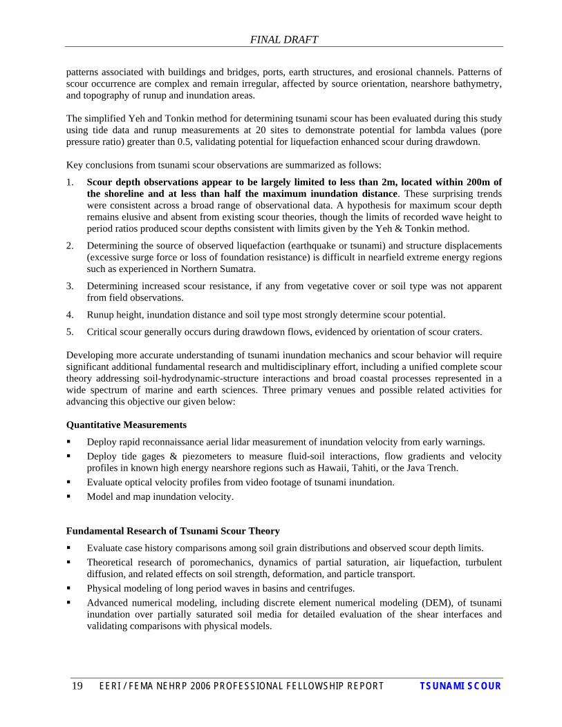
patterns associated with buildings and bridges, ports, earth structures, and erosional channels. Patterns of scour occurrence are complex and remain irregular, affected by source orientation, nearshore bathymetry, and topography of runup and inundation areas. The simplified Yeh and Tonkin method for determining tsunami scour has been evaluated during this study using tide data and runup measurements at 20 sites to demonstrate potential for lambda values (pore pressure ratio) greater than 0.5, validating potential for liquefaction enhanced scour during drawdown. Key conclusions from tsunami scour observations are summarized as follows:
1. Scour depth observations appear to be largely limited to less than 2m, located within 200m of the shoreline and at less than half the maximum inundation distance. These surprising trends were consistent across a broad range of observational data. A hypothesis for maximum scour depth remains elusive and absent from existing scour theories, though the limits of recorded wave height to period ratios produced scour depths consistent with limits given by the Yeh & Tonkin method.
2. Determining the source of observed liquefaction (earthquake or tsunami) and structure displacements (excessive surge force or loss of foundation resistance) is difficult in nearfield extreme energy regions such as experienced in Northern Sumatra.
3. Determining increased scour resistance, if any from vegetative cover or soil type was not apparent from field observations.
4. Runup height, inundation distance and soil type most strongly determine scour potential.
5. Critical scour generally occurs during drawdown flows, evidenced by orientation of scour craters. Developing more accurate understanding of tsunami inundation mechanics and scour behavior will require significant additional fundamental research and multidisciplinary effort, including a unified complete scour theory addressing soil-hydrodynamic-structure interactions and broad coastal processes represented in a wide spectrum of marine and earth sciences. Three primary venues and possible related activities for advancing this objective our given below: Quantitative Measurements
Deploy rapid reconnaissance aerial lidar measurement of inundation velocity from early warnings. Deploy tide gages & piezometers to measure fluid-soil interactions, flow gradients and velocity
profiles in known high energy nearshore regions such as Hawaii, Tahiti, or the Java Trench. Evaluate optical velocity profiles from video footage of tsunami inundation. Model and map inundation velocity.
Fundamental Research of Tsunami Scour Theory
Evaluate case history comparisons among soil grain distributions and observed scour depth limits. Theoretical research of poromechanics, dynamics of partial saturation, air liquefaction, turbulent
diffusion, and related effects on soil strength, deformation, and particle transport. Physical modeling of long period waves in basins and centrifuges. Advanced numerical modeling, including discrete element numerical modeling (DEM), of tsunami
inundation over partially saturated soil media for detailed evaluation of the shear interfaces and validating comparisons with physical models.

FINAL DRAFT
20 EERI / FEMA NEHRP 2006 PROFESSIONAL FELLOWSHIP REPORT TSUNAMI SCOUR
Continued Development of Engineering Procedures & Codes
Establish performance goals for tsunami resistance and a timetable for adoption into future versions of national codes and guidelines including ASCE 7, FEMA 455, the Coastal Construction Manual and national FIRM maps.
Adopt revised tsunami scour resistance provisions in the model Honolulu Bldg Code, and state standards adopted by Washington, Oregon and California.
Develop regional resilience for tsunami attacks, adopting the UNDP Hyogo Framework, IOC provisions, and model codes adopted by strongly affected countries such as Japan, India, Indonesia and Thailand.
The following appendices are attached and complete this report: Appendix A. Tsunami Scour Evaluation Site Photos Appendix B. Tsunami Scour Evaluation Data Tables B1-B3 Appendix C. Tide Gage Records Appendix D. General Tsunami Scour Photos

FINAL DRAFT
21 EERI / FEMA NEHRP 2006 PROFESSIONAL FELLOWSHIP REPORT TSUNAMI SCOUR
REFERENCES Government Manuals : Briaud, J.L., Chen, H.C., et al, 2003. Complex Pier Scour and Contraction Scour in Cohesive Soils, NCHRP 24-15, EFA-SRICOS Method, Transportation Research Board, National Research Council, Wash D.C. Richardson, E.V., and Davis, S.R., 2001. Evaluating Scour at Bridges, Hydraulic Engineering Circular No. 18 (HEC 18), 4th Edition, FHWA-NHI-01-001, National Highway Institute, Federal Highway Association, Wash D.C. Lagasse, P.F., Schall, J.D., Richardson, E.V., 2003. Stability at Bridge Structures, Hydraulic Engineering Circular No. 20 (HEC 20), 3rd Edition, FHWA NHI-001-02, National Highway Institute, Federal Highway Association, Wash D.C. Lagasse, P.F., Zevenbergen, L.W., Schall, J.D., Clopper, P.E., 2001. Bridge Scour and Stream Instability Countermeasures, Hydraulic Engineering Circular No. 23 (HEC 23), 2nd Edition, FHWA NHI-001-003, National Highway Institute, Federal Highway Association, Wash D.C. Wagner, C.R., Mueller, D.S., et. al., 2006. Scour at Contracted Bridges, NCHRP 24-14, Transportation Research Board, National Research Council, Wash D.C.. Zevenbergen, L.W., Lagasse, P.F, and Edge, B.L.,2004. Tidal Hydrology, Hydraulics, and Scour at Bridges, Hydraulic Engineering Circular No.25 (HEC 25), 1st Edition, FHWA-NHI-05-077, National Highway Institute, Federal Highway Association, Wash D.C. Hughes, S.E., 1999. Equilibrium Scour Depth at Tidal Inlets, Coastal Engineering Technical Note IV-18, US Army Corps of Engineers ERDC, Vicksburg, Miss. Hwang, D., Francis, M., Singh, J.P., Dirhamsyah, M., Sartohadi, J. Aziz, S. Willison, R. Choi, B.H., Stein, S., Borrero, J., Thio, H.K., Ratti, C. Bergado, D., 2006. Coastal Hazard Mitigation Guidebook for the Regions and Communities of the Province of Nanggroe Aceh Darussalam and the Islands of Nias, Province of North Sumatera, Executing Agency for the Rehabilitation and Reconstruction of NAD-Nias, Jakarta. PARI, 2004. Yeh, H., Robertson, I. and Preuss, J., 2005. Development of Design Guidelines for Structures that Serve as Vertical Evacuation Sites, Washington Division of Geology and Earth Resources, Open File Report 2005-4. Olympia, WA. Texts: Chien, N.,et al 1999. Mechanics of Sediment Transport, ASCE,VA. Einstein, H, et al, 1971. Sedimentation, Workshop Proceedings, Ed. Shen, UC Berkeley Conference. Einstein, H., 1950 USDA bed load function circular

FINAL DRAFT
22 EERI / FEMA NEHRP 2006 PROFESSIONAL FELLOWSHIP REPORT TSUNAMI SCOUR
Einsein, H., 1940 German sediment circular Li, Robert (Yue), 2006. Introduction to Bridge Scour, Michigan Bridge Conference, Mi. Sleath, J.F., 1984. Sea Bed Mechanics, J Wiley & Sons, New York. Whitehouse, R., 1998. Scour at Marine Structures, Thomas Telford, London. Yalin, M.S., 1972. Mechanics of Sediment Transport, Pergamon Press, Oxford. Pinet. P.R., 2003. Invitation to Oceanography, Jone & Bartlett, Mass.; Hjulstroms diagram adapted from Sunborg, A., The River Klavaren, Geografika Annaler 38 (1956): 125-316 Fragackis, 2001 Sleath, J.F.A.1984. Seabed Mechanics, Wiley and Sons Shen 1971 Papers: Arduino et al, 2001 Bartlett 2006 Booker and Seed Borerro, Liu, Fritz, et al (Spectra) 2006 Bray, 2006 Carrier and Yeh, 2003 DeBoer, 2003 DeGroot, ASCE 2006 Ettema, 2004, 2006 – Einstein reflections Finn, 1983 Fritz and Borrero (spectra) 2006 Fu et al, 2005 dispersion Fredsoe, 2006 Green and Mitchell, 2004 Gajo, 1995 Hoffmans & Verheij, 1997 Hwang, Francis, et al 2006 Idriss & Boulanger, 2004 Itasca, 2006 Jeng 2003 Kaa, 2005 ANN Lobkovsky, 2004 Moody, 1944 Nataraja & Gill, 1994 Peterson, et al 2006 Rollins and Seed, 1987 Sakai, 1992 wave liquef Seed & Idriss, 1972 Shields, 1936 Stewart 2007 Sumer and Fredsoe, 2006 Synokalis, Yeh, Lui, 2001 Terzaghi, 1925 diffusion Terzaghi 1936 boiling Tonkin and Yeh, 2003 Yeh and Tonkin 2004 Yeh (spectra), 2006

FINAL DRAFT
23 EERI / FEMA NEHRP 2006 PROFESSIONAL FELLOWSHIP REPORT TSUNAMI SCOUR
Yeh (2006) Maximum Fluid Forces in the Tsunami Runup Zone Journal of Waterway Port and Coastal Engineering, November/December, ASCE, Reston, VA. Yeh, Francis, et al (2006) Effects of the 2004 Great SumatraTsunami: Southeast Indian Coast, Journal of Waterway Port and Coastal Engineering, November/December, ASCE, Reston, VA. Yeh (JND 2007) Design Forces for Onshore Structures, Journal of Disaster Research, Vol. 2, No. 6. Yeh (1997) Youd et al, 2001 (ASCE/NCEER liq) Youd, Hansen & Bartlett, 2002 Zen & Yamazaki, 1991, 93 Stewart, J., 2007 EERI mtg Tide Data Sea Level Center, University of Hawaii Prof. Pramood, Chulalonkorn Univ. National Aquatic Resources Agency of Sri Lanka, India Space Agency NOAA Personal Communication Djou, S.K., Dames & Moore (ret)., 2006. Fritz, H, Ga Tech, 2006 Houston, J.L., Army COE Vicksburg, 2006. Mojfeld, H.A., PMEL, 2006. Siripong, A., Univ of Chulalongkorn, 2006

FINAL DRAFT
24 EERI / FEMA NEHRP 2006 PROFESSIONAL FELLOWSHIP REPORT TSUNAMI SCOUR
APPENDIX A TSUNAMI SCOUR EVALUATION SITE PHOTOS
Figure A-1, Tsunami scour sites and tide gage locations:
Road Scour (RS) 1-12 Structure Scour (SS) 1-8

APPENDIX A – SCOUR TABLE PHOTOS Draft
A-1 EERI / FEMA NEHRP 2006 PROFESSIONAL FELLOWSHIP REPORT TSUNAMI SCOUR
Photo No. RS-1 Ref: Aceh Harbor, Sumatra (M Francis) 12m runup Description: Waterfront peninsular road to Aceh Harbor with bay sound to the left and housing remnants in the foreground. Entire road was washed out. New fill visible in foreground. Photo taken Feb 2005. Fine dark brown natural silty sands.
Photo No. RS-1A Ref: Aceh Harbor, Sumatra, (M Francis) 12m runup Description: South shore of Krun Aceh River looking west toward direction of tsunami advance. River shore erosion visible with remnants of bridge piers in background. The entire reinforced concrete bridge was destroyed. Similar bridges further inland were overtopped but not destroyed.

APPENDIX A – SCOUR TABLE PHOTOS Draft
A-2 EERI / FEMA NEHRP 2006 PROFESSIONAL FELLOWSHIP REPORT TSUNAMI SCOUR
Photo No. RS-2 Ref: Gle Bruk, Sumatra (J Borrero, USC) 15m runup Description: Oceanfront river bridge with complete erosion of south abutment and riverbank. Med to coarse sand deposits.
Photo No. RS-3 Ref: Great Nicobar (JP Singh, United Sikhs) 11m runup Description: Oceanfront road with steep shoreline and strong longshore current erosion. Runup damaged trees in background. Large angular cobbles and boulders with silty compacted roadbed.

APPENDIX A – SCOUR TABLE PHOTOS Draft
A-3 EERI / FEMA NEHRP 2006 PROFESSIONAL FELLOWSHIP REPORT TSUNAMI SCOUR
Photo No. RS-4 Ref: Nazar, Pt. Blair, Andaman (GSI) 4m runup Description: Oceanfront road at east mouth of agricultural valley which was indundated. Seawall overtopped and damaged in area of localized energy concentration. Deposits of coarse gravel, cobbles and boulders.
Photo No. RS-5 Ref: Bang Thao, Phuket, Thailand (Siripong) 8m runup Description: Scour of asphalt pavement and vegetated dunes. Mixed coarse road debris and natural sands.

APPENDIX A – SCOUR TABLE PHOTOS Draft
A-4 EERI / FEMA NEHRP 2006 PROFESSIONAL FELLOWSHIP REPORT TSUNAMI SCOUR
Photo No. RS-6 Ref: Fisheries Pier, Phangaa, Thailand (Siripong) Runup NA
Description: Scour of beachfront pier migrated to asphalt approach, creating sinkhole. Reinforced concrete structure with clean uniform fine to medium sand.
Photo No. RS-6A Ref: Sarasin Bridge, Phangaa, Thailand (Panoramio.com) Runup NA Description: Bridge connecting Phuket Island to mainland Thailand. Bridge did not overtop, and no reported damage, though housing damage on shoreline was extensive.

APPENDIX A – SCOUR TABLE PHOTOS Draft
A-5 EERI / FEMA NEHRP 2006 PROFESSIONAL FELLOWSHIP REPORT TSUNAMI SCOUR
Photo No. RS-7 Ref: Hot spring village, Kuraburi, Phangaa, Thailand (Siripong) Runup NA Description: Scour pocket in asphalt road near beachfront. Utilities exposed. Mixed fine sands with coarse silty roadbed and asphalt rubble.
Photo No. RS-7A Ref: Kuraburi, Phangaa, Thailand (Siripong) Runup NA Description: Scour pockets in sandy open field on landside of shoreline road. Clean medium uniform sands.

APPENDIX A – SCOUR TABLE PHOTOS Draft
A-6 EERI / FEMA NEHRP 2006 PROFESSIONAL FELLOWSHIP REPORT TSUNAMI SCOUR
Photo No. RS-8 Ref: Prapas Beach, Laem Son Natl Park, Ranong, Thailand (Siripong) Runup NA
Description: Roadside scour and asphalt damage. Mixed sands, silty sand and debris.
Photo No. RS-9 Ref: Marina Beach, Chennai (Yeh) 5m runup Description: Broad beachfront runup overtopping promenade and roadway, undermining sidewalk. Medium to fine uniform sand with concrete rubble.

APPENDIX A – SCOUR TABLE PHOTOS Draft
A-7 EERI / FEMA NEHRP 2006 PROFESSIONAL FELLOWSHIP REPORT TSUNAMI SCOUR
Photo No. RS-9A Ref: Port of Chennai (Francis) 5m runup
Description: Inner harbor with tetrapod breakwater in background, overtopped by tsunami with no significant damage. Turning basin entrance caissons in foreground did experience 6-9 inches settlement and over 1ft outward rotation from drawdown.
Photo No. RS-10 Ref: Kottapatnam, Andrah Pradesh (Francis) 4m runup Description: Beachfront road berm in front of concrete homes on piers. Roadway overtopped and reduced energy of runup inundation at home. Silty clay berm experience limited erosion scour, and remained intact, forcing drawdown around the south end in background.

APPENDIX A – SCOUR TABLE PHOTOS Draft
A-8 EERI / FEMA NEHRP 2006 PROFESSIONAL FELLOWSHIP REPORT TSUNAMI SCOUR
Photo No. RS-11 Ref: Arugam Bay Bridge, Sri Lanka(T Springer and R Robertson, CH2M Hill) 5m runup
Description: 3m diameter 10m deep bridge caissons overtopped with 4.5m wave, experiencing 1m settlement and outward rotation during drawdown, damaging structural integrity and requiring extensive repairs.
Photo No. RS-12 Ref: Ambalangoda, Sri Lanka (Kyoto University) 5m runup Description: Beachfront roadway with adjacent railroad and vegetation serving as protective barriers. Clean uniform sand railroad ballast completely scoured.

APPENDIX A – SCOUR TABLE PHOTOS Draft
A-9 EERI / FEMA NEHRP 2006 PROFESSIONAL FELLOWSHIP REPORT TSUNAMI SCOUR
Photo No. SS-1 Ref: Lock Nga, Sumatra (Hwang) 20m runup Description: Large open mosque on grassy coastal plain experienced complete inundation and roof overtopping. Only minor shallow surface erosion. No significant structural damage. Natural gravel and sand residue found on rooftop.
Photo No. SS-1A Ref: Loch Nga, Sumatra, (Hwang) 20m runup Description: Aerial view of large mosque in Photo SS-1 which was entirely inundated. Grassy vegetation remained largely intact throughout the plain.

APPENDIX A – SCOUR TABLE PHOTOS Draft
A-10 EERI / FEMA NEHRP 2006 PROFESSIONAL FELLOWSHIP REPORT TSUNAMI SCOUR
Photo No. SS-2 Ref: Kamala Beach, Phuket, Thailand (Bergado) 6m runup Description: Beachfront villas on reinforced masonry shallow piers experience completed undermining scour, but generally rigid structure did not settle or rotate.
Photo No. SS-2A Ref: Bang Tao, Phuket, Thailand (Francis) 6m runup Description: Waterfront villa experienced inundation to rooftop level with complete scour damage to marina wall and backfill and undermining of pier footing. Silty sands exposed with drawdown debris.

APPENDIX A – SCOUR TABLE PHOTOS Draft
A-11 EERI / FEMA NEHRP 2006 PROFESSIONAL FELLOWSHIP REPORT TSUNAMI SCOUR
Photo No. SS-3 Ref: Khao Lak, Phangnaa Thailand (Bergado) 12m runup Description: Villa supported on open piers atop beachfront dune. Structure completely overtopped. Piers remained intact. Extensive scour along drawdown channel. Medium uniform sands with some drawdown debris.
Photo No. SS-3A Ref: Khao Lak, Phangaa, Thailand (Francis) 12m runup Description: Beachfront hotel inundated to third floor. Extensive scour along open beachfront. Compacted clayey fill and retaining wall scour limited to southwest corner. Otherwise remained intact with limited undermining of perimeter footings.

APPENDIX A – SCOUR TABLE PHOTOS Draft
A-12 EERI / FEMA NEHRP 2006 PROFESSIONAL FELLOWSHIP REPORT TSUNAMI SCOUR
Photo No. SS-4 Ref: Koh Khao Jomtien, Phangaa, Thailand (Francis) 10m runup Description: New beachfront two story pile supported hotel experience rooftop inundation and scour pockets under perimeter footings. Clean uniform medium sands.
Photo No. SS-4A Ref: Koh Khao Jomtien, Phangaa, Thailand (Francis) 10m runup Description: New beachfront villa completely destroyed. Reinforced concrete slabs undermined and footing piers exposed with scour of wastewater sumps and plumbing. This was a typical sight through this and other nearby resorts. Clean medium uniform sands.

APPENDIX A – SCOUR TABLE PHOTOS Draft
A-13 EERI / FEMA NEHRP 2006 PROFESSIONAL FELLOWSHIP REPORT TSUNAMI SCOUR
Photo No. SS-5 Ref: Kalapakkom, Tamil Nadu, India (Yeh) 5m runup Description: Schoolhouse located 125 m inland from shore in Kalapakkom. Scour patterns mainly along seaward corner of buildings. Medium uniform sands with debris. Drain line exposed.
Photo No. SS-6 Ref: Cuddalore, Tamil Nadu, India (Francis) 6m runup Description: Unreinforced masonry structure completely inundated and rooftop destroyed. Scour limited to northeast corner of building. Dense silty fine sands with surface debris.

APPENDIX A – SCOUR TABLE PHOTOS Draft
A-14 EERI / FEMA NEHRP 2006 PROFESSIONAL FELLOWSHIP REPORT TSUNAMI SCOUR
Photo No. SS-7 Ref: Alappad, Kerala, India (M Joseph, GSI) 3m runup Description: Inundation scour and drawdown forces caused seaward rotation and settlement of rigid beachront home on shallow slab foundation. Medium to coarse clean sands
Photo No. SS-7A Ref: Sri Lanka, (Lui et al, EERI) 3m runup
Description: Beachfront masonry structure remnant. Foundation scour of seaward corner and undermining collapsed grade beam in foreground. Clean to silty sand with debris.

APPENDIX A – SCOUR TABLE PHOTOS Draft
A-15 EERI / FEMA NEHRP 2006 PROFESSIONAL FELLOWSHIP REPORT TSUNAMI SCOUR
Photo No. SS-8 Ref: Xaafun, Somalia (Fritz) 5m runup Description: Beachfront masonry home with scour erosion of shallow footing. Structure rotated seaward and settled several inches, typical of damage in the area.
Photo No. SS-8A Ref: Xaafun, Somalia (Fritz) 5m runup
Description: View of tsunami inundated beachfront near damaged homes and aerial cargo ropeway remnants.

FINAL DRAFT
25 EERI / FEMA NEHRP 2006 PROFESSIONAL FELLOWSHIP REPORT TSUNAMI SCOUR
APPENDIX B TSUNAMI SCOUR EVALUATION DATA TABLE Table B-1 Selected site conditions for tsunami scour evaluation Case Number Region Survey
Location Latitude (N) Longitude (E) Runup Height (m)
Dist. to Shoreline D1
(m)
Scoured Soil Type
Surface Cover
Observed Scour Ds (m)
Scour Feature
Runup Data Source
RS-1 Banda Aceh, Sumatra Aceh Harbor 5.5619° 95.2895° 12 20 Medium silty
sandbeachfront peninsula 2.5 Road/bridge
washout M Francis
RS-2 Gle Bruk, Sumatra
Oceanfront bridge 5.1987° 95.283° 15 50 Coarse/med
beach sandbeachfront barrier spit 2.5 Abutment
washout J Borrero
RS-3 Nicobar Islands Great Nicobar 6.9° 93.9° 11 5 Silty gravel base & bldrs
jungle slope, rocky coast 4 Road scour JP Singh
RS-4 Pt Blair, Andaman Nazar 11.6571° 92.7543° 4 5 Med to fine
sand w/gvlbeachfront w/seawall 1 Seawall road
scourGeolSurvey of
India
RS-5 Bang Tao, Phuket Bang Tao 8.0094° 98.2928° 8 75 Med to Fine
Sand thin palm trees 2 Road scour A Siripong
RS-6 Phangaa Fisheries Pier,Bridge 8.308° 98.2708° na 75 Uniform Fine
to Med Sandbeachfront with spit 1.5 Abutment
sinkhole A Siripong
RS-7 Kuraburi, Phangaa
Hot Spring Village 9.3181° 98.3822° na 125 Med to Fine
Sand thin palm trees 1 Road scour D Bergado
RS-8 Laem Son Natl Park, Ranong Prapas Beach 9.3685° 98.3964° na 60 Fine sand agricultural
field w/ trees 1 Road boil A Siripong
RS-9 Chennai, India Marina Beach 13.0344° 80.2799° 5 100 Med to Fine Sand
very large beach 1 Road scour H Yeh
RS-10 Kottapatnam, India Palipan Beach 15.4359° 80.1772° 4 50 Med to Fine
Sandlarge beach / peanut fields 0.5 Road scour M Francis
RS-11 Ambalangoda Sri Lanka
Oceanfront Railway 6.2292° 80.0544° 5 30 Med to Fine
Sandbeach / adjacent road 1.5 Railway scour Kyoto Univ
RS-12 Arugam Bay, Sri Lanka
Oceanfront Bridge 6.8551° 81.8312° 7 180 Med Clean
Sandbeachfront river 2 Bridge scour Fritz,EERI
SS-1 Aceh Province, Indonesia
Lock Nga Mosque 5.4942° 95.2351° 20 640 Med Clean
Sand grassed plain 0.5 Flow thru structure D Hwang
SS-2 Phuket, Thailand Kamala home 7.955° 98.283° 6 30 Med to Fine Sand beachfront 2 Footing scour M Francis, A
Siripong
SS-3 Khao Lak, Thailand
Bang Niang hotel/villas 8.6658° 98.2436° 12 50 Med Clean
Sandbeachfront, dune/palms 2 Footing scour M Francis
SS-4 Koh Khao, Thailand Jomtien hotel 8.8748° 98.2681° 10 200 Fine clean
sandstripped beachfront 2 Footing &
utilities M Francis
SS-5 Tamil Nadu, India
Kalapakkom School 12.5063° 80.1615° 5 120 Med to Fine
Sandopen schoolyard 1.5 Footing scour H Yeh
SS-6 Tamil Nadu, India
Cuddalore Home 11.7461° 79.788° 6 60 Silty fine sand beachfront w/
palm trees 0.5 Footing scour H Yeh
SS-7 Kerala, India Allapad Home 9.5° 76.33° 3 60 Silty fine sand beachfront w/ palm trees 1 Footing scour GeolSurvey of
India
SS-8 Somalia Xaafuun Peninsula 10.422° 51.259° 5 150 Med to fine
clean sand arid beachfront 0.5 Footing scour H Fritz Table B-2 Tide Gage Conditions Applied to Selected Sites
Case Number Tide Gage Location Latitude Longitude Distance to
Site (km)Max Falling Tide ΔP(cm) ΔT (min)
RS-1 Sibolga 1.7406° 98.7736° 575 238 50RS-2 Sibolga 1.7406° 98.7736° 545 238 50RS-3 Chatam Island 11.6867° 92.72° 550 220 30RS-4 Chatam Island 11.6867° 92.72° 5 220 30RS-5 Tapanoi 7.801° 98.406° 25 215 5RS-6 Tapanoi 7.801° 98.406° 60 215 5RS-7 Kuraburi 9.2263° 98.3721° 10 180 30RS-8 Kuraburi 9.2263° 98.3721° 15 180 30RS-9 Chennai 13.1° 80.3° 7 260 10RS-10 Chennai 13.1° 80.3° 260 260 10RS-11 Colombo 6.9544° 79.8501° 80 220 20RS-12 Colombo 6.9544° 79.8501° 220 220 20SS-1 Sibolga 1.7406° 98.7736° 570** 238 50SS-2 Tapanoi 7.801° 98.406° 22 215 5SS-3 Tapanoi 7.801° 98.406° 95 215 5SS-4 Kuraburi 9.2263° 98.3721° 40 180 30SS-5 Chennai 13.1° 80.3° 65 260 10SS-6 Chennai 13.1° 80.3° 160 260 10SS-7 Kochi 9.96° 76.26° 50 120 30SS-8 Salalah 16.943° 54.002° 775 265 12

FINAL DRAFT
26 EERI / FEMA NEHRP 2006 PROFESSIONAL FELLOWSHIP REPORT TSUNAMI SCOUR
Table B-3 Tsunami Scour Evaluation Results for Selected Sites
Case Number Scoured Soil Type
Scour Feature
Observed Scour Ds (m)
Λ(0) @Cv = 100 cm2/s
Λ(0) @Cv = 800 cm2/s
Λ(ds)@Cv = 100 cm2/s
Λ(ds)@Cv = 800 cm2/s
RS-1Medium silty sand
Road/bridge washout 2.5 0.54 0.19 0.44 0.18
RS-2Coarse/med beach sand
Abutment washout 2.5 0.54 0.19 0.44 0.18
RS-3Silty gravel base & bldrs Road scour 4 0.65 0.23 0.43 0.20
RS-4Med to fine sand w/gvl
Seawall road scour 1 0.65 0.23 0.59 0.22
RS-5Med to Fine Sand Road scour 2 1.56 0.55 0.93 0.46
RS-6Uniform Fine to Med Sand
Abutment sinkhole 1.5 1.56 0.55 1.05 0.48
RS-7Med to Fine Sand Road scour 1 0.53 0.19 0.48 0.18
RS-8 Fine sand Road boil 1 0.53 0.19 0.48 0.18
RS-9Med to Fine Sand Road scour 1 1.33 0.47 1.11 0.44
RS-10Med to Fine Sand Road scour 0.5 1.33 0.47 1.22 0.46
RS-11Med to Fine Sand
Railway scour 1.5 0.80 0.28 0.66 0.26
RS-12Med Clean Sand Bridge scour 2 0.80 0.28 0.61 0.26
SS-1Med Clean Sand
Flow thru structure 0.5 0.54 0.19 0.52 0.19
SS-2Med to Fine Sand
Footing scour 2 1.56 0.55 0.93 0.46
SS-3Med Clean Sand
Footing scour 2 1.56 0.55 0.93 0.46
SS-4Fine clean sand
Footing & utilities 2 0.53 0.19 0.43 0.17
SS-5Med to Fine Sand
Footing scour 1.5 1.33 0.47 1.01 0.43
SS-6 Silty fine sandFooting scour 0.5 1.33 0.47 1.22 0.46
SS-7 Silty fine sandFooting scour 1 0.35 0.13 0.32 0.12
SS-8Med to fine clean sand
Footing scour 0.5 1.24 0.44 1.14 0.43

FINAL DRAFT
27 EERI / FEMA NEHRP 2006 PROFESSIONAL FELLOWSHIP REPORT TSUNAMI SCOUR
APPENDIX C TIDE GAGE RECORDS Sibolga, Indonesia Chatam Island, Andaman
Tapanoi, Thailand Kuraburi, Thailand
Chennai, India Kochi, India
Salalah, Oman
-2
-1.5
-1
-0.5
0
0.5
1
1.5
2
1 1441 2881 4321 5761 7201 86410
0.51
1.52
2.53
3.54
1 1441 2881 4321 5761 7201 8641

FINAL DRAFT
28 EERI / FEMA NEHRP 2006 PROFESSIONAL FELLOWSHIP REPORT TSUNAMI SCOUR

FINAL DRAFT
29 EERI / FEMA NEHRP 2006 PROFESSIONAL FELLOWSHIP REPORT TSUNAMI SCOUR
Tapanoi
-1.5
-1.0
-0.5
0.0
0.5
1.0
1.5
2.0
1 61 121 181 241 301
Time (min)
Leve
l (m
)
15
432
ΔP = 215 cmΔT =5 min
Kuraburi
0.0000.5001.0001.5002.0002.5003.0003.5004.000
0 0 0 0 0 0 0time (hrs)
tide
el (m
)
ΔP = 170 cmΔT =35 min

FINAL DRAFT
30 EERI / FEMA NEHRP 2006 PROFESSIONAL FELLOWSHIP REPORT TSUNAMI SCOUR

FINAL DRAFT
31 EERI / FEMA NEHRP 2006 PROFESSIONAL FELLOWSHIP REPORT TSUNAMI SCOUR

FINAL DRAFT
32 EERI / FEMA NEHRP 2006 PROFESSIONAL FELLOWSHIP REPORT TSUNAMI SCOUR
APPENDIX D GENERAL TSUNAMI SCOUR PHOTOS 50 selected scour photos are provided, classified by site conditions using the following notation: Geomorphic - General Scour A Aerial observation CM Coastline migration CS Channel scour TD Tsunami deposit Infrastructure - Local & General Scour SS Building structure scour BS Bridge scour RS Road scour HS Harbor scour WS Seawall scour

FINAL DRAFT
33 EERI / FEMA NEHRP 2006 PROFESSIONAL FELLOWSHIP REPORT TSUNAMI SCOUR

FINAL DRAFT
34 EERI / FEMA NEHRP 2006 PROFESSIONAL FELLOWSHIP REPORT TSUNAMI SCOUR