Embed Size (px)
Citation preview

INSTALLATION INSTRUCTIONS
TT-1364 7/12c
Original Issue Date: 5/04
Model: 4--40 kW Generator Sets Equipped with the ADC 2100 Controller
Market: Marine, Mobile, and Residential/Commercial
Subject: ADC 2100 Controller Replacement KitsGM34969, GM46826, and GM48301
Introduction
Use these instructions to replace, configure, and adjust
the controller on generator sets originally equipped with
the ADC 2100 controller. See Figure 1 for ADC 2100
Controller identification. Controller replacement,
configuration, and adjustment must be performed by an
authorized distributor/dealer or trained service
technician.
Check the controller settings before replacing the
controller. Incorrect controller settings can cause the
generator set to shut down or operate incorrectly.
Follow the instructions in this document to verify that the
controller settings are correct for the generator set and
optional accessories before removing the controller.
Always check for loose connections, faulty wiring, blown
fuses, a dead battery, or other simple problems before
replacing parts. Check the SCR module (GM28483)
connections, F1 fuse, and wiring before replacing the
controller. Refer to the generator set service manual for
troubleshooting and repair procedures.
Note: The installer must set up the replacement
controller after installation. Be sure to read and
follow the entire procedure to configure and
adjust the new controller.
See Figure 2 for ADC 2100 controller replacement kit
numbers.
Read the entire installation procedure before beginning
installation. Perform the steps in the order shown.
1
2
4
3
1. LED display
2. Select button (use for setup and adjustment only)3. Upanddownarrowbuttons (use for setupandadjustmentonly)
4. Generator set master switch
GM28707A-C
Figure 1 ADC 2100 Controller
Generator Set Model
Controller PartNumber
(for reference only) Kit Number
5/7.3ECD and 4/6EFCD
GM47982 GM4803110--15EGD, 9/11EFGD, and13--15EGZD
20EORZD/EORZDBspec numbersGM38880-SA1 andGM38880-SA2 (See “Allother models” below forother spec numbers)
GM42037 GM4682628/32EOZD and23/25/27/28EFOZDspec numbersGM55347-GA1 to -GA16(See “All other models”below for other specnumbers)
All other models GM28707 GM34969
Figure 2 ADC 2100 Replacement Kit Numbers

2 TT-1364 7/12
Safety Precautions
Observe the following safety precautionswhile installing
the kit.
Accidental starting.Can cause severe injury or death.
Disconnect the battery cables beforeworking on the generator set.
Remove the negative (--) lead firstwhen disconnecting the battery.Reconnect the negative (--) lead lastwhen reconnecting the battery.
WARNING
Disabling the generator set. Accidental starting can
cause severe injury or death. Before working on thegenerator set or connected equipment, disable the generatorset as follows: (1) Move thegenerator setmaster switch to theOFFposition. (2) Disconnect thepower to thebattery charger.(3) Remove the battery cables, negative (--) lead first.Reconnect the negative (--) lead last when reconnecting the
battery. Follow these precautions to prevent starting of thegenerator set by an automatic transfer switch, remotestart/stop switch, or engine start command from a remotecomputer.
Hazardous voltage.Can cause severe injury or death.
Operate the generator set only whenall guards and electrical enclosures
are in place.
Moving parts.
WARNING
Servicing thegenerator setwhen it is operating. Exposedmoving parts can cause severe injury or death. Keephands, feet, hair, clothing, and test leads away from the belts
and pulleys when the generator set is running. Replaceguards, screens, and covers before operating the generatorset.
Before Replacing the Controller
Read the information in this section before starting the
controller replacement procedure.
Controller Application Program
The controller’s application program version number is
shown on a label on the controller circuit board (under
the back cover). The program version number is also
displayed on the LED screen during the key sequence to
enter the configuration mode. (The controller must be
connected to the generator set.) Hold the Select button
and move the generator set master switch to the RUN
position. After about 5 seconds, the application
program version number will be displayed on the
controller display. For example, 01.18 will be displayed
for program version 1.18.
Notes:
� The ADC 2100 application program does not apply to
the APU, ADC-RES, DC-RET, ADC II, ADC IId, RDC,
DC, DC2, or RDC2 controllers.
� Use controller application code version 1.18 or later
on controllers that are not equipped with the P7
jumper. Do not load earlier code versions on
controllers that do not have the P7 jumper.
� ADC application program version 3.10 or later can be
used on all generator sets equipped with the
ADC 2100 controller. If you have a controller with an
earlier version of code, upgrading to version 3.10 or
higher is recommended.
� Use controller application code version 3.20 or later
for all generator models using remote digital gauge
GM50577 and gauge kit GM50822.
See Tech Tools for a summary of all code version
information/history. The most current code version, at
the time of this printing, is version 3.32. Upgrading to the
latest version is highly recommended.

TT-1364 7/12 3
Go to Tech Tools, Software, to find the latest software
information and obtain application program software.
Use the Program Loader Software and a personal
computer to update the controller’s application program
after controller installation, when necessary. Obtain the
latest version of the application program and the
Program Loader software through Tech Tools or contact
your generator set distributor. Refer to TT-1285,
Program Loader Instructions, for instructions to load the
application program onto the controller.
Continuous Power Mode Jumper P7 Eliminated
Controllers manufactured after 7/18/2005 (with serial
number 2051415 and later) no longer include the
continuous power mode jumper P7. See Figure 3.
These controllers use application program version
numbers 1.18 and above.
Note: Do not load ADC application program versions
numbered below 1.18 onto the upgraded (P7
jumper eliminated) ADC 2100.
See Service Bulletin SB-652 for more information about
the elimination of the continuous power mode jumper.
Note: See power down times in Figure 9.
1. P7 jumper, if equipped
2. J15 connector
3. J16 connector
4. P1 connection
1
tt1364
2
3
4
Figure 3 P7 Jumper Location, if equipped
(controller back cover removed)
Controller Replacement
1. Before replacing the controller, record the following
information about the generator set. This
information is required for configuration of the new
controller.
Model
Market
� Marine
� Standby (Residential/Comm)
� Mobile
Voltage, VAC
Frequency � 60 Hz � 50 Hz
Phases � 1 Ph � 3 Ph
Battery Voltage � 12 VDC � 24 VDC
Optional sender kitsinstalled
� None
� Oil pressure sender kitGM32112-KA1 or -KP1
� OP and WT sendersGM45891-KA1
� Oil pressure sender kitGM50552-KA1
Remote gaugesconnected
� None
� Remote Digital GaugeGM32337-KP1 or -KP2
� 3” Smartcraft gaugeGM46035-KP1
� 2” Smartcraft gaugeGM50822-KP1
Figure 4 Generator Set Information Required for
Controller Setup
2. Place the generator set master switch in the OFF
position.
3. Disconnect the power to the battery charger, if
equipped.
4. Disconnect the generator set engine starting
battery(ies), negative (--) lead first.
5. Open the junction box to gain access to the back of
the ADC 2100. Disconnect the controller at P1,
J15, and J16. See Figure 3.
6. Models ECD/EFCD, EGD/EFGD, and EGZD only:
Disconnect the CO sensor harness at the 4-pin
connector.
7. Remove four controller mounting screws and
remove the old controller.

4 TT-1364 7/12
8. Models ECD/EFCD, EGD/EFGD, and EGZD only:
a. Remove the CO sensor module assembly from
the old controller or obtain a new CO sensor
module assembly GM46362.
b. Mount the assembly onto the 4 mounting studs
on the back of the new controller GM47982.
9. Install the new controller and secure it with the
mounting screws.
10. Reconnect the P1, J15, and J16 connectors. On
models ECD/EFCD, EGD/EFGD, and EGZD,
connect the CO sensor harness to the 4-pin
connector. Close the junction box.
11. This step applies to models 10/13/15EG, 10/13/
15ERG, 15/30RES, and 15/30RYG only. For all
other models, proceed to step 12.
a. Check the generator set serial number and
refer to Figure 5. On these generator set
modelswith serial numbers before 2053692,
it is necessary to cut the gray/orange lead in the
wiring harness when an ADC 2100 controller
with application code version 1.18 or later is
installed.
Generator sets with higher serial numbers use
different wiring harnesses and do not require
this procedure. Proceed to step 12 for units
with serial numbers above 2053692.
b. Remove the cover on the ECM connector.
c. Locate pin #9. See the X mark in Figure 6.
d. Cut and remove a 1-in. section of the gray/
orange lead entering pin #9 in the wiring
harness at the ECM connector. This allows the
ADC 2100 (and not the ECM) to control the
starting circuit.
e. Replace the cover on the ECM connector.
Model Market Before Serial Number
10EG13EG15EG
Marine
2053692
10ERG13ERG15ERG
Commercial/Recreational
Mobile
15RES30RES15RYG30RYG
Residential/Commercial
Figure 5 Models Requiring Starting Circuit Procedure
(for application code version 1.18 or higher)
1
GM34393
1. Cut the gray/orange lead to pin 9 for
ADC version 1.18 or greater only.
VBAT
CAM --
18 ORANGE/BLUE 1616 BROWN/BLUE 1617 BROWN/GREEN 1630 LT BLUE/WHITE 1835 TAN/DK GREEN 1833 LT GRN 1838 DK BLUE 18
32 TAN 1831 YELLOW/GRAY 1839 PURPLE/YELLOW 1836 DK BLUE/YELLOW 18
19 BLACK 1620 BLACK 16
49 BLACK/LT GREEN 1850 LT GREEN/RED 18
21 PINK/TAN 1855 DK GREEN/ORANGE 184142
1314
11 PURPLE/WHITE 1812 WHITE PURPLE 18
22 RED/TAN 1623 RED/TAN 169 GRAY/ORANGE 188 WHITE/BLACK 187 TAN/BLACK 1810 WHITE/LT BLUE 1853 PURPLE/LT BLUE 1854 LT BLUE/DK BLUE 1824 PINK/WHITE 1825 TAN/ORANGE 1837 LT GREEN/BLACK 1856 YELLOW/LT GREEN 1826 LT BLUE/BLACK 1847 BLACK/WHITE 1829 PURPLE/DK BLUE 1840 TAN/BROWN 1848 YELLOW/DK BLUE 1834 GRAY/ DK BLUE 1815 WHITE/RED 1843 BLUE/PINK 1844 BLUE/WHITE 1851 DK GREEN 1852 ORANGE 1827 YELLOW 1828 YELLOW/BLK 1815
2 RED/WHITE 186
INJ +INJ 1INJ 2
AUX OUT 2AUX ANA PD1
MAPFPP
IATECTIVS
AUX ANA PU1
POWER GROUNDPOWER GROUND
ANA_RTN5 VOLT REF.
VSWEGO 1KNK +KNK --
CAM +
CRANK +CRANK --
VBAT
STARTER LOCKOUTFUEL LOCKOFF
FUEL PUMPRELAY CONTROL
TPS1TPS2
DBW +DBW --
OIL PRESSURETACHMIL
AUX ANA PD2AUX OUT 1
FUEL SELECTAUX ANA PU2GOV SELECT
GASEOUS TRIMCAN +CAN --
RS 232 TXRS 232 RX
COIL 1COIL 2
UNUSEDUNUSEDUNUSED
INJ7UNUSED
UNUSED
ECM (E--CONTROLS)
BATT (--)
BATT (+)
43
X
WIRE COLORS MAY BE DIFFERENT THAN SHOWN.
Figure 6 ECM Wiring for 10/13/15EG,
10/13/15ERG, 15/30RES, and 15/30RYG
Models, S/N before 2053692

TT-1364 7/12 5
12. Check that the generator set master switch is in the
OFF position.
13. Reconnect the generator set engine starting
battery, negative (--) lead last.
14. Reconnect power to the battery charger, if
equipped.
15. Check the controller application software version
number:
a. Hold the Select button and move the generator
set master switch to the RUN position. After
about 5 seconds, the application software
version number will be displayed on the
controller display.
b. Compare the software version number to Tech
Tools. Use Kohler’s Program Loader to load
the latest version of the application code onto
the controller. Go to Tech Tools, Software, or
refer to TT-1285 for instructions to obtain and
load the latest version of the controller
application code, if necessary.
16. Follow instructions in the Controller Configuration
Section to change the new controller’s
configuration settings to match the generator set
system voltage and frequency, unit configuration,
engine type, engine data input types, battery
voltage, and communications settings.
Note: Be sure to save the new settings
immediately as instructed before exiting the
configuration mode. The changes will be
lost if the controller times out before the
settings are saved.
17. Use a multimeter to check the output voltage and
frequency. Follow the instructions in the Voltage
and Speed Adjustment Section to adjust the output
voltage, speed, and stability settings on the ADC
controller. Save the settings immediately after
adjustment is complete.
Note: Models with mechanical governors do not
use the ADC controller’s engine speed
adjustment menus.

6 TT-1364 7/12
Controller Configuration
Replacement controllers are factory-set for the
8.5/12RES generator set. The installer must set the
replacement controller to the appropriate configuration
for the generator set model. See Figure 12 through
Figure 15 to determine the appropriate settings for your
generator set model. Settings are also summarized in
Appendix A.
After you have identified the appropriate settings for
your generator set, follow the instructions in Figure 16
through Figure 18 to change the controller settings.
Enter the configuration mode while the engine is not
running and then step through the parameters. Use the
up (∧) and down (∨) arrow buttons to select the
appropriate setting for each parameter.
Optional Sender Kits and Ed Setting
The installation of optional sender kits may require a
change to the Ed (engine data inputs) setting. See
Figure 7 for the Ed settings with optional sender kits.
“No Change” means the installation of the kit does not
require a change to the Ed setting.
Note: The Ec setting can affect the Ed setting. If you
change the Ec setting, check the Ed setting and
change it if necessary to match the value shown
in the tables for your unit.
Note: Installation of an optional electronic governor kit
with amagnetic pickup does not require a change
to the Ed setting.
Model Sender Kit Ed
5/7.3ECD
4/6EFCD
None 0
GM45891-KA1 * No Change
6EOD
4.5EFOD
None 1
GM32112-KA1 and -KP1 � 3
GM50552-KA1 * No Change
GM47164-KP1 � No Change
8--32EOZD
6.5--28EFOZD
None 1
GM32112-KA1 and -KP1 * 3
GM50552-KA1 � No Change
10/13/15EG
9/11EFG
13/15EGZ
None 1
GM35299-KA1 and -KP1 * 3
10/13/15EGD
9/11EFGD
13/15EGZD
None 3
10--20EORD/B
10--20EORZD/B
9--16.5EFORD/B
9--16.5EFORZD/B
GM46308-KP1 � No Change
* OP and WT sender kits
� Oil pressure sender kits
� Electronic governor kit
Note: For other models, refer to the parameter setting tables.
Figure 7 Ed Settings with Optional Sender Kits
Cn Communication Parameter
See Figure 8 and Figure 9 for communication
parameter settings. If your generator set is connected to
a remote digital gauge, refer to Figure 8, Figure 9, and
the instruction sheet provided with the gauge to
determine the communication parameter Cn setting.
Gauge Kit Gauge Description
CnSetting Description
None — Cn00 No CAN communication
GM32337-KP1 Remote Digital Gauge forMarine
Cn01 J1939 CAN communication
GM32337-KP2 � Remote Digital Gauge forMobile and Residential/Commercial
Cn01 J1939 CAN communication, continuous power to ADC*
Cn06 J1939 CAN communication, ADC power down after 1 hour for either:*a. Remote start/stop switchb. Automatic transfer switchc: Remote digital gauge GM32337-KP2 with remote start/stop switchand replacement harness
GM46035-KP1 Three-Inch Digital Gauge Cn02 Smartcraft� gauge for generator set #1 with ECM �
Cn03 Smartcraft� gauge for generator set #2 with ECM �
Cn04 Smartcraft� gauge for generator set #3 with ECM �
Cn05 Smartcraft� gauge for generator set #4 with ECM �
Cn07 Smartcraft� gauge for generator set #1 without ECM �
GM50822-KP1 Two-Inch Digital Gauge Cn08 Smartcraft� 2-inch gauge for generator set #1 with ECM �
Cn09 Smartcraft� 2-inch gauge for generator set #1 without ECM �
* For ADCs with removable power mode jumpers, refer to TT-1439 for power down information.� Smartcraft� settings for ADC code version 2.00 or higher only, for models 5/7.3ECD and 4/6EFCD.� Smartcraft� settings for ADC code version 2.20 or higher only.
� ADC code version 3.12 or higher is recommended with this gauge kit.
Figure 8 Communication Parameter Cn Settings (optional gauges are available on selected models only)

TT-1364 7/12 7
Power Modes
With the generator set master switch in the AUTO
position, there are three possible controller power
modes:
� 48-hour power down. If the communication
parameter setting is Cn00, Cn02, Cn03, Cn04, Cn05,
or Cn07, the controller will power down after 48 hours
of inactivity. If the generator set has been started, the
controller will power down 48 hours after the
generator set stops.
� Continuous power mode. If the ADC 2100
communications parameter is set to Cn01, the
controller will not power down. The controller remains
powered at all times to maintain CAN
communications and allow remote start commands
from the CAN gauge. A battery charger is
recommended to maintain the battery.
� 1-hour power down. Setting the communications
parameter to Cn06, Cn08, or Cn09 will cause the
ADC 2100 to power down after 1 hour of inactivity. In
this mode, a remote start/stop switch or the generator
set master switch must be used to activate the
controller after it has powered down. ADC 2100
application code version 1.21 or higher is required for
the 1-hour power down option.
Note: After controller power-down, a remote digital
gauge will not have power and therefore will
not be able to send a start signal to activate the
controller.
Note: Use of the 2-inch digital gauge allows wake-up
of the controller remotely.
Note: Figure 9 describes the power down time for
various CAN settings. This only applies when
the master switch is in the AUTO position.
CAN Setting Power Down Time Application Notes
Cn00 48 Hours No remote gauge used, remote start/stop via switch only
Cn01 * Never/None 3-inch J1939 gauge with no sleep mode
Cn02 � 48 Hours 3-inch Smartcraft� gauge with SECM engine (Ec04)
Cn03 � 48 Hours 3-inch Smartcraft� gauge with SECM engine (Ec04)
Cn04 � 48 Hours 3-inch Smartcraft� gauge with SECM engine (Ec04)
Cn05 � 48 Hours 3-inch Smartcraft� gauge with SECM engine (Ec04)
Cn06 * 1 Hour 3-inch J1939 gauge with one hour sleep mode
Cn07 � 48 Hours 3-inch Smartcraft� gauge with non-SECM engine (not Ec04)
Cn08 � 1 Hour � 2-inch Smartcraft� gauge with SECM engine (Ec04)
Cn09 � 1 Hour � 2-inch Smartcraft� gauge with non-SECM engine (not Ec04)
* For use with gauge GM30565 and gauge kit GM32337.� For use with gauge GM45905 and gauge kit GM46035.� For use with gauge GM50577 and gauge kit GM50822.
� Before version 3.20, the power down time is 48 hours.
Figure 9 Power Down Times for CAN settings

8 TT-1364 7/12
Uc Market Parameter
TheUc settings are listed in Figure 10 and also shown in
the parameter tables for each model.
Uc Setting Description
Uc00 Marine
Uc01 Standby (Residential/Commercial)
Uc02 Mobile
Figure 10 Uc Market Parameter
CO Parameter
The CO parameter does not appear for all models. N/A
(not applicable) is shown in the table if the CO setting
does not apply.
For some models, CO must be set to 0 (zero) or 1 as
shown in the tables. An incorrect setting may cause the
generator set to shut down on a fault and display the
fault code CO-3 or CO-6.
CA Parameter
The CA parameter appears in the advanced
configuration mode only when the engine configuration
is set to Ec02, Ec11, or Ec12 and the communication
parameter is set to Cn01. CA sets the CANbus address
for the controller as shown in Figure 11. The default
setting is CA00.
The CA parameter appears only in application code
versions 3.12 or higher.
CA Setting CANbus Address
CA00 * 0x00 *
CA01 � 0xEA �
* Default setting
� SAE J1939 compliant
Figure 11 CA CANbus Address Parameter
Configuration Mode Time Out
The controller will automatically exit the configuration
modewithout saving any changes after about 1minute if
no buttons are pressed. Start the configuration
procedure over again from the beginning if the controller
exits the configuration mode before the settings have
been saved.
Voltage and Speed Adjustment
After setting the system configuration, use a multimeter
to check the generator set output voltage and frequency.
Use the controller to adjust the output if the voltage and/
or frequency are not within the acceptable range for the
application.
The diagrams in Figure 19 and Figure 20 outline the
procedures for voltage and speed adjustments. The
generator set must be running during these
adjustments. Use a multimeter to measure the
generator set output voltage and frequency during
adjustments.
The engine speed (frequency) adjustment menus are
not accessible on models with mechanical governors.
Note: Save your settings after making adjustments. If
the settings are not saved, the system returns to
the previous settings after the generator set shuts
down.

TT-1364 7/12 9
Controller Parameter Settings, Marine Models
Marine GasolineModel
Freq.Hz Voltage, Phases
Volts,Hz Market
EngineType
DataInputs CO
BatteryVoltage
CANbusComm.
Uu* Uc Ec Ed� CO Bt Cn�
ECDEFCD
4EFCD 50
230 V, 1 Ph, 2 W 2
0 4 0 1 122, 3, 4, 5,or 8 �
115/230 V, 1 Ph, 3 W 6
115 V, 1 Ph, 2 W 5
5ECD 60
120/240 V, 1 Ph, 3 W 1
120 V, 1 Ph, 3 W 0
120 V, 1 Ph, 2 W 0
6EFCD 50
230 V, 1 Ph, 2 W 2
115/230 V, 1 Ph, 3 W 6
115 V, 1 Ph, 2 W 5
7.3ECD 60
120/240 V, 1 Ph, 3 W 1
120 V, 1 Ph, 3 W 0
120 V, 1 Ph, 2 W 0
EGEFG
9EFG 50 230 V, 1 Ph, 2 W 2
0 31 (std.) or3 (ops) �
0 12 0, 1, or 6 �
10EG 60120/240 V, 1 Ph, 3 W 1
120 V, 1 Ph, 2 W 0
11EFG 50 230 V, 1 Ph, 2 W 2
13EG 60 120/240 V, 1 Ph, 3 W 1
15EG 60 120/240 V, 1 Ph, 3 W 1
EGZ
13EGZ 60 120/240 V, 1 Ph, 3 W 1
0 101 (std.) or3 (ops) �
0 12
0, 1, or 6 �
15EGZ 60 120/240 V, 1 Ph, 3 W 10, 1, 6, 7,or 9 �
EGDEFGD
9EFGD 50 230 V, 1 Ph, 2 W 2
0 3 3 1 120, 1, 6, 7, or
9 �
10EGD 60120/240 V, 1 Ph, 3 W 1
120 V, 1 Ph, 2 W 0
11EFGD 50 230 V, 1 Ph, 2 W 2
13EGD 60 120/240 V, 1 Ph, 3 W 1
15EGD 60 120/240 V, 1 Ph, 3 W 1
EGZD13EGZD 60 120/240 V, 1 Ph, 3 W 1
0 10 3 1 1215EGZD 60 120/240 V, 1 Ph, 3 W 1
* Use voltage/frequency parameters Uu07--Uu23 only with ADC application program version 1.20 or higher.
� See Figure 7 for Ed settings with optional sender kits.
� See Figure 8 and Figure 9 for Cn settings with optional digital gauges (gauges are available on selected models only).
Note: Replacement controllers from Kohler Aftermarket Parts are shipped with factory settings for the 8.5/12RES.Note: Setting the Ec parameter automatically selects the Ed parameter for the standard data inputs for that engine.
If you change Ec, check the Ed setting.Note: 13/15EGZ models with PTO require application program version 1.21 or higher.Note: 10/13/15EGD and 13/15EGZD models with PTO require application version 3.00 or higher.
Figure 12 Controller Parameter Settings, Marine Gasoline Models

10 TT-1364 7/12
Marine Diesel Model
Freq.Hz Voltage, Phases
Volts,Hz Market
EngineType
DataInputs
BatteryVoltage
CANbusComm.
Uu* Uc Ec Ed� Bt Cn�
EODEFOD
4.5EFOD 50
230 V, 1 Ph, 2 W 2
0 1
1 (std.)or
3 (ops) �12
0, 1, 6, 7,or 9 �
115/230 V, 1 Ph, 3 W 6
240 V, 1 Ph, 2 W 13
6EOD 60
120/240 V, 1 Ph, 3 W 1
0 1120 V, 1 Ph, 3 W 0
120 V, 1 Ph, 2 W 0
EOZDEFOZD
6.5EFOZD 50
230 V, 1 Ph, 2 W 2
0 1
1 (std.)or
3 (ops) �12
0, 1, or 6 �115/230 V, 1 Ph, 3 W 6
240 V, 1 Ph, 2 W 13
7EFOZD 50
230 V, 1 Ph, 2 W 2
0 10, 1, 6, 7,or 9 �
115/230 V, 1 Ph, 3 W 6
240 V, 1 Ph, 2 W 13
8EOZD 60
120/240 V, 1 Ph, 3 W 1
0 1 0, 1, or 6 �120 V, 1 Ph, 3 W 0
120 V, 1 Ph, 2 W 0
8.5EFOZD(3 Ph)
50 230/400 V, 3 Ph, 4 W, Wye 3 0 2
1 (std.)or
3 (ops) �12 or 24
0, 1, 6, 7,or 9 �
9EFOZD(1 Ph)
50
230 V, 1 Ph, 2 W 2
0 2115/230 V, 1 Ph, 3 W 6
240 V, 1 Ph, 2 W 13
9EOZD 60
120/240 V, 1 Ph, 3 W 1
0 1
1 (std.)or
3 (ops) �12120 V, 1 Ph, 3 W 0
120 V, 1 Ph, 2 W 0
10EOZD(1 Ph)
60
120/240 V, 1 Ph, 3 W 1
0 2
1 (std.)or
3 (ops) �12 or 24
120 V, 1 Ph, 3 W 0
120 V, 1 Ph, 2 W 0
10EOZD(3 Ph)
60
120/240 V, 3 Ph, 4 W, Delta 10
0 2127/220 V, 3 Ph, 4 W, Wye 16
220/380 V, 3 Ph, 4 W, Wye 19
240/416 V, 3 Ph, 4 W, Wye 20
11EFOZD 50
230 V, 1 Ph, 2 W 2
0 2115/230 V, 1 Ph, 3 W 6
240 V, 1 Ph, 2 W 13
11.5EFOZD(3 Ph)
50
115/230 V, 1 Ph, 3 W 6
0 2
115/230 V, 3 Ph, 4 W, Delta 14
110/190 V, 3 Ph, 4 W, Wye 17
120/208 V, 3 Ph, 4 W, Wye 18
220/380 V, 3 Ph, 4 W, Wye 21
230/400 V, 3 Ph, 4 W, Wye 3
240/416 V, 3 Ph, 4 W, Wye 22
13EOZD 60 120/240 V, 1 Ph, 3 W 1 0 2
13EFOZD 50
230 V, 1 Ph, 2 W 2
0 2115/230 V, 1 Ph, 3 W 6
240 V, 1 Ph, 2 W 13
* Use voltage/frequency parameters Uu07--Uu23 only with ADC application program version 1.20 or higher.
� See Figure 7 for Ed settings with optional sender kits.
� See Figure 8 and Figure 9 for Cn settings with optional digital gauges (gauges are available on selected models only).
Note: Replacement controllers from Kohler Aftermarket Parts are shipped with factory settings for the 8.5/12RES.Note: Setting the Ec parameter automatically selects the Ed parameter for the standard data inputs for that engine.
If you change Ec, check the Ed setting.
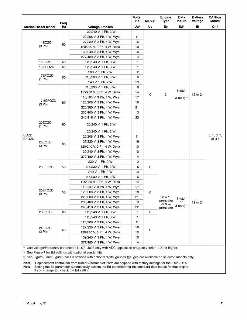
TT-1364 7/12 11
Marine Diesel Model
CANbusComm.
BatteryVoltage
DataInputs
EngineTypeMarket
Volts,Hz
Voltage, Phases
Freq.HzMarine Diesel Model Cn�BtEd�EcUcUu*Voltage, Phases
Freq.Hz
EOZDEFOZD
14EOZD(3 Ph)
60
120/240 V, 1 Ph, 3 W 1
0 2
1 (std.)or
3 (ops) �12 or 24
0, 1, 6, 7,or 9 �
120/208 V, 3 Ph, 4 W, Wye 11
127/220 V, 3 Ph, 4 W, Wye 16
120/240 V, 3 Ph, 4 W, Delta 10
139/240 V, 3 Ph, 4 W, Wye 10
277/480 V, 3 Ph, 4 W, Wye 4
15EOZD 60 120/240 V, 1 Ph, 3 W 1
15.5EOZD 60 120/240 V, 1 Ph, 3 W 1
17EFOZD(1 Ph)
50
230 V, 1 Ph, 2 W 2
115/230 V, 1 Ph, 3 W 6
240 V, 1 Ph, 2 W 13
17.5EFOZD(3 Ph)
50
115/230 V, 1 Ph, 3 W 6
115/230 V, 3 Ph, 4 W, Delta 14
110/190 V, 3 Ph, 4 W, Wye 17
120/208 V, 3 Ph, 4 W, Wye 18
220/380 V, 3 Ph, 4 W, Wye 21
230/400 V, 3 Ph, 4 W, Wye 3
240/416 V, 3 Ph, 4 W, Wye 22
20EOZD(1 Ph)
60 120/240 V, 1 Ph, 3 W 1
20EOZD(3 Ph)
60
120/240 V, 1 Ph, 3 W 1
120/208 V, 3 Ph, 4 W, Wye 11
127/220 V, 3 Ph, 4 W, Wye 16
120/240 V, 3 Ph, 4 W, Delta 10
139/240 V, 3 Ph, 4 W, Wye 10
277/480 V, 3 Ph, 4 W, Wye 4
20EFOZD 50
230 V, 1 Ph, 2 W 2
0
2 w.o.preheateror 9 w/
preheater
1 (std.)or
3 (ops) �12 or 24
115/230 V, 1 Ph, 3 W 6
240 V, 1 Ph, 2 W 13
20EFOZD(3 Ph)
50
115/230 V, 1 Ph, 3 W 6
0
115/230 V, 3 Ph, 4 W, Delta 14
110/190 V, 3 Ph, 4 W, Wye 17
120/208 V, 3 Ph, 4 W, Wye 18
220/380 V, 3 Ph, 4 W, Wye 21
230/400 V, 3 Ph, 4 W, Wye 3
240/416 V, 3 Ph, 4 W, Wye 22
23EOZD 60 120/240 V, 1 Ph, 3 W 1 0
24EOZD(3 Ph)
60
120/240 V, 1 Ph, 3 W 1
0
120/208 V, 3 Ph, 4 W, Wye 11
127/220 V, 3 Ph, 4 W, Wye 16
120/240 V, 3 Ph, 4 W, Delta 10
139/240 V, 3 Ph, 4 W, Wye 10
277/480 V, 3 Ph, 4 W, Wye 4
* Use voltage/frequency parameters Uu07--Uu23 only with ADC application program version 1.20 or higher.
� See Figure 7 for Ed settings with optional sender kits.
� See Figure 8 and Figure 9 for Cn settings with optional digital gauges (gauges are available on selected models only).
Note: Replacement controllers from Kohler Aftermarket Parts are shipped with factory settings for the 8.5/12RES.Note: Setting the Ec parameter automatically selects the Ed parameter for the standard data inputs for that engine.
If you change Ec, check the Ed setting.

12 TT-1364 7/12
Marine Diesel Model
CANbusComm.
BatteryVoltage
DataInputs
EngineTypeMarket
Volts,Hz
Voltage, Phases
Freq.HzMarine Diesel Model Cn�BtEd�EcUcUu*Voltage, Phases
Freq.Hz
EOZDEFOZD
23EFOZD(1 Ph)
50
230 V, 1 Ph, 2 W 2
0 71 (std.)or
3 (ops) �12 or 24
0, 1, 6, 7,or 9 �
115/230 V, 1 Ph, 3 W 6
240 V, 1 Ph, 2 W 13
23EFOZD(3 Ph)
50
115/230 V, 1 Ph, 3 W 6
115/230 V, 3 Ph, 4 W, Delta 14
110/190 V, 3 Ph, 4 W, Wye 17
120/208 V, 3 Ph, 4 W, Wye 18
220/380 V, 3 Ph, 4 W, Wye 21
230/400 V, 3 Ph, 4 W, Wye 3
240/416 V, 3 Ph, 4 W, Wye 22
25EFOZD(1 Ph)
50
230 V, 1 Ph, 2 W 2
115/230 V, 1 Ph, 3 W 6
240 V, 1 Ph, 2 W 13
25EFOZD(3 Ph)
50
115/230 V, 1 Ph, 3 W 6
115/230 V, 3 Ph, 4 W, Delta 14
110/190 V, 3 Ph, 4 W, Wye 17
120/208 V, 3 Ph, 4 W, Wye 18
220/380 V, 3 Ph, 4 W, Wye 21
230/400 V, 3 Ph, 4 W, Wye 3
240/416 V, 3 Ph, 4 W, Wye 22
27EFOZD(1 Ph)
50
230 V, 1 Ph, 2 W 2
115/230 V, 1 Ph, 3 W 6
240 V, 1 Ph, 2 W 13
27EFOZD(3 Ph)
50
115/230 V, 1 Ph, 3 W 6
115/230 V, 3 Ph, 4 W, Delta 14
110/190 V, 3 Ph, 4 W, Wye 17
120/208 V, 3 Ph, 4 W, Wye 18
220/380 V, 3 Ph, 4 W, Wye 21
230/400 V, 3 Ph, 4 W, Wye 3
240/416 V, 3 Ph, 4 W, Wye 22
28EFOZD(1 Ph)
50
230 V, 1 Ph, 2 W 2
115/230 V, 1 Ph, 3 W 6
240 V, 1 Ph, 2 W 13
28EFOZD(3 Ph)
50
115/230 V, 1 Ph, 3 W 6
115/230 V, 3 Ph, 4 W, Delta 14
110/190 V, 3 Ph, 4 W, Wye 17
120/208 V, 3 Ph, 4 W, Wye 18
220/380 V, 3 Ph, 4 W, Wye 21
230/400 V, 3 Ph, 4 W, Wye 3
240/416 V, 3 Ph, 4 W, Wye 22
* Use voltage/frequency parameters Uu07--Uu23 only with ADC application program version 1.20 or higher.
� See Figure 7 for Ed settings with optional sender kits.
� See Figure 8 and Figure 9 for Cn settings with optional digital gauges (gauges are available on selected models only).
Note: Replacement controllers from Kohler Aftermarket Parts are shipped with factory settings for the 8.5/12RES.Note: Setting the Ec parameter automatically selects the Ed parameter for the standard data inputs for that engine.
If you change Ec, check the Ed setting.

TT-1364 7/12 13
Marine Diesel Model
CANbusComm.
BatteryVoltage
DataInputs
EngineTypeMarket
Volts,Hz
Voltage, Phases
Freq.HzMarine Diesel Model Cn�BtEd�EcUcUu*Voltage, Phases
Freq.Hz
EOZDEFOZD
28EOZD(1 Ph)
60 120/240 V, 1 Ph, 3 W 1
0 71 (std.)or
3 (ops) �12 or 24
0, 1, 6, 7,or 9 �
28EOZD(3 Ph)
60
120/240 V, 1 Ph, 3 W 1
120/208 V, 3 Ph, 4 W, Wye 11
127/220 V, 3 Ph, 4 W, Wye 16
120/240 V, 3 Ph, 4 W, Delta 10
139/240 V, 3 Ph, 4 W, Wye 10
277/480 V, 3 Ph, 4 W, Wye 4
32EOZD(1 Ph)
60 120/240 V, 1 Ph, 3 W 1
32EOZD(3 Ph)
60
120/240 V, 1 Ph, 3 W 1
120/208 V, 3 Ph, 4 W, Wye 11
127/220 V, 3 Ph, 4 W, Wye 16
120/240 V, 3 Ph, 4 W, Delta 10
139/240 V, 3 Ph, 4 W, Wye 10
277/480 V, 3 Ph, 4 W, Wye 4
* Use voltage/frequency parameters Uu07--Uu23 only with ADC application program version 1.20 or higher.
� See Figure 7 for Ed settings with optional sender kits.
� See Figure 8 and Figure 9 for Cn settings with optional digital gauges (gauges are available on selected models only).
Note: Replacement controllers from Kohler Aftermarket Parts are shipped with factory settings for the 8.5/12RES.Note: Setting the Ec parameter automatically selects the Ed parameter for the standard data inputs for that engine.
If you change Ec, check the Ed setting.
Figure 13 Controller Parameter Settings, Marine Diesel Models

14 TT-1364 7/12
Controller Parameter Settings, Residential/Commercial Models
Residential/CommercialModel
Freq.Hz Voltage, Phases
Volts,Hz Market
EngineType
DataInputs CO
BatteryVoltage
CANbusComm.
Uu * Uc Ec Ed� CO Bt Cn�
8.5RES and12RES
60 120/240 V,1 Ph, 3W 1 1 0 5 N/A 12 0
50 115/230 V,1 Ph 6 1 0 5 N/A 12 0
15RES 60 120/240 V, 1 Ph, 3 W 1 1 3 1 N/A 12 0, 1, or 6 �
30RES 60 120/240 V, 1 Ph, 3 W 1 1 6 1 N/A 12 0, 1, or 6 �
15RESA 60 120/240 V, 1 Ph, 3 W 1 1 12 N/A N/A 12 0, 1, or 6 �
30RESA 60 120/240 V, 1 Ph, 3 W 1 1 11 N/A N/A 12 0, 1, or 6 �
15RYG 60
120/240 V, 1 Ph, 3 W 1
1 3 1 N/A 12 0, 1, or 6 �
120/208 V, Wye, 3 Ph, 4 W 11
127/220 V, Wye, 3 Ph, 4 W 16
120/240 V, Delta, 3 Ph, 4 W 10
139/240 V, Wye , 3 Ph, 4 W 10
277/480 V, Wye, 3 Ph, 4 W 4
30RYG
60
120/240 V, 1 Ph, 3 W 1
1 6 1 N/A 12 0, 1, or 6 �
120/208 V, Wye, 3 Ph, 4 W 11
127/220 V, Wye, 3 Ph, 4 W 16
120/240 V, Delta, 3 Ph, 4 W 10
277/480 V, Wye, 3 Ph, 4 W 4
139/240 V, Wye, 3 Ph, 4 W 10
50
110/220 V, 1 Ph, 3 W 7
1 6 1 N/A 12 0, 1, or 6 �
110/190 V, Wye, 3 Ph, 4 W 17
120/208 V, Wye, 3 Ph, 4 W 18
110/220 V, Delta, 3 Ph, 4 W 17
220/380 V, Wye, 3 Ph, 4 W 21
240/416 V, Wye, 3 Ph, 4W 22
115/200 V, Wye, 3 Ph, 4 W 23
230/400, Wye, 3 Ph, 4 W 3
15REYG 60
120/240 V, 1 Ph, 3 W 1
1 12 N/A N/A 12 0, 1, or 6 �
120/208 V, Wye, 3 Ph, 4 W 11
127/220 V, Wye, 3 Ph, 4 W 16
120/240 V, Delta, 3 Ph, 4 W 10
139/240 V, Wye , 3 Ph, 4 W 10
277/480 V, Wye, 3 Ph, 4 W 4
30REYG 60
120/240 V, 1 Ph, 3 W 1
1 11 N/A N/A 12 0, 1, or 6 �
120/208 V, Wye, 3 Ph, 4 W 11
127/220 V, Wye, 3 Ph, 4 W 16
120/240 V, Delta, 3 Ph, 4 W 10
277/480 V, Wye, 3 Ph, 4 W 4
139/240 V, Wye, 3 Ph, 4 W 10
* Use voltage/frequency parameters Uu07--Uu23 only with ADC application program version 1.20 or higher.
� See Figure 7 for Ed settings with optional sender kits.
� See Figure 8 and Figure 9 for Cn settings with optional digital gauges (gauges are available on selected models only).
Note: Replacement controllers from Kohler Aftermarket Parts are shipped with factory settings for the 8.5/12RES.
Note: Setting the Ec parameter automatically selects the appropriate Ed parameter for the standard data inputs for that engine.
If you change Ec, check the Ed setting.

TT-1364 7/12 15
Residential/CommercialModel
CANbusComm.
BatteryVoltageCO
DataInputs
EngineTypeMarket
Volts,Hz
Voltage, Phases
Freq.Hz
Residential/CommercialModel Cn�BtCOEd�EcUcUu *Voltage, Phases
Freq.Hz
30REYG 50
110/220 V, 1 Ph, 3 W 7
1 11 1 N/A 12 0, 1, or 6 �
110/190 V, Wye, 3 Ph, 4 W 17
120/208 V, Wye, 3 Ph, 4 W 18
110/220 V, Delta, 3 Ph, 4 W 17
220/380 V, Wye, 3 Ph, 4 W 21
240/416 V, Wye, 3 Ph, 4W 22
115/200 V, Wye, 3 Ph, 4 W 23
230/400, Wye, 3 Ph, 4 W 3
10REOD,10REOZD,15REOD,15REOZD,20REOD, and20REOZD
60
120/240 V, 1 Ph 1
1 21 (std.)or
3 (ops) �N/A 12 0, 1, or 6 �
120/208 V, 3 Ph 11
127/220 V, 3 Ph 16
120/240 V, 3 Ph 10
139/240 V, 3 Ph 10
220/380 V, 3 Ph 19
277/480 V, 3 Ph 4
50
110/220 V, 1 Ph 7
1 2
1 (std.)or
3 (ops) �N/A 12 0, 1, or 6 �
110/190 V, 3 Ph 17
110/220 V, 3 Ph 15
220/380 V, 3 Ph 21
230/400 V, 3 Ph 3
240/416 V, 3 Ph 22
* Use voltage/frequency parameters Uu07--Uu23 only with ADC application program version 1.20 or higher.
� See Figure 7 for Ed settings with optional sender kits.
� See Figure 8 and Figure 9 for Cn settings with optional digital gauges (gauges are available on selected models only).
Note: Replacement controllers from Kohler Aftermarket Parts are shipped with factory settings for the 8.5/12RES.
Note: Setting the Ec parameter automatically selects the appropriate Ed parameter for the standard data inputs for that engine.
If you change Ec, check the Ed setting.
Figure 14 Controller Parameter Settings, Residential/Commercial Models
16 TT-1364 7/12
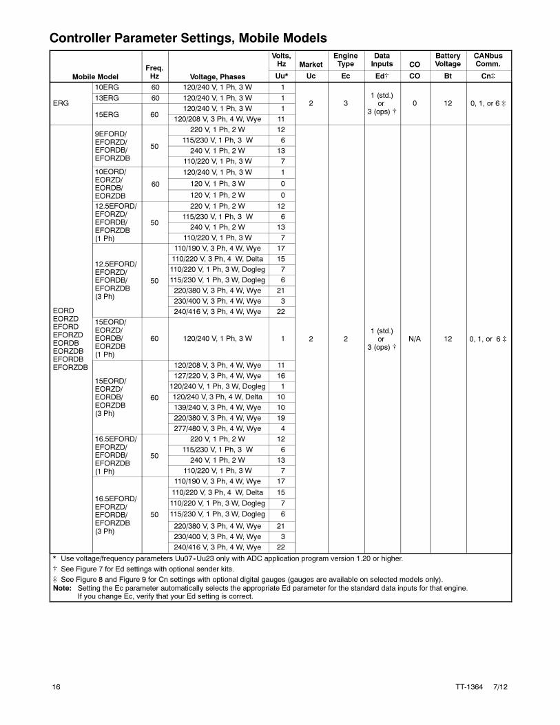
Controller Parameter Settings, Mobile Models
Mobile Model
Freq.Hz Voltage, Phases
Volts,Hz Market
EngineType
DataInputs CO
BatteryVoltage
CANbusComm.
Uu* Uc Ec Ed� CO Bt Cn�
ERG
10ERG 60 120/240 V, 1 Ph, 3 W 1
2 31 (std.)or
3 (ops) �0 12 0, 1, or 6 �
13ERG 60 120/240 V, 1 Ph, 3 W 1
15ERG 60120/240 V, 1 Ph, 3 W 1
120/208 V, 3 Ph, 4 W, Wye 11
EORDEORZDEFORDEFORZDEORDBEORZDBEFORDBEFORZDB
9EFORD/EFORZD/EFORDB/EFORZDB
50
220 V, 1 Ph, 2 W 12
2 21 (std.)or
3 (ops) �N/A 12 0, 1, or 6 �
115/230 V, 1 Ph, 3 W 6
240 V, 1 Ph, 2 W 13
110/220 V, 1 Ph, 3 W 7
10EORD/EORZD/EORDB/EORZDB
60
120/240 V, 1 Ph, 3 W 1
120 V, 1 Ph, 3 W 0
120 V, 1 Ph, 2 W 0
12.5EFORD/EFORZD/EFORDB/EFORZDB(1 Ph)
50
220 V, 1 Ph, 2 W 12
115/230 V, 1 Ph, 3 W 6
240 V, 1 Ph, 2 W 13
110/220 V, 1 Ph, 3 W 7
12.5EFORD/EFORZD/EFORDB/EFORZDB(3 Ph)
50
110/190 V, 3 Ph, 4 W, Wye 17
110/220 V, 3 Ph, 4 W, Delta 15
110/220 V, 1 Ph, 3 W, Dogleg 7
115/230 V, 1 Ph, 3 W, Dogleg 6
220/380 V, 3 Ph, 4 W, Wye 21
230/400 V, 3 Ph, 4 W, Wye 3
240/416 V, 3 Ph, 4 W, Wye 22
15EORD/EORZD/EORDB/EORZDB(1 Ph)
60 120/240 V, 1 Ph, 3 W 1
15EORD/EORZD/EORDB/EORZDB(3 Ph)
60
120/208 V, 3 Ph, 4 W, Wye 11
127/220 V, 3 Ph, 4 W, Wye 16
120/240 V, 1 Ph, 3 W, Dogleg 1
120/240 V, 3 Ph, 4 W, Delta 10
139/240 V, 3 Ph, 4 W, Wye 10
220/380 V, 3 Ph, 4 W, Wye 19
277/480 V, 3 Ph, 4 W, Wye 4
16.5EFORD/EFORZD/EFORDB/EFORZDB(1 Ph)
50
220 V, 1 Ph, 2 W 12
115/230 V, 1 Ph, 3 W 6
240 V, 1 Ph, 2 W 13
110/220 V, 1 Ph, 3 W 7
16.5EFORD/EFORZD/EFORDB/EFORZDB(3 Ph)
50
110/190 V, 3 Ph, 4 W, Wye 17
110/220 V, 3 Ph, 4 W, Delta 15
110/220 V, 1 Ph, 3 W, Dogleg 7
115/230 V, 1 Ph, 3 W, Dogleg 6
220/380 V, 3 Ph, 4 W, Wye 21
230/400 V, 3 Ph, 4 W, Wye 3
240/416 V, 3 Ph, 4 W, Wye 22
* Use voltage/frequency parameters Uu07--Uu23 only with ADC application program version 1.20 or higher.
� See Figure 7 for Ed settings with optional sender kits.
� See Figure 8 and Figure 9 for Cn settings with optional digital gauges (gauges are available on selected models only).Note: Setting the Ec parameter automatically selects the appropriate Ed parameter for the standard data inputs for that engine.
If you change Ec, verify that your Ed setting is correct.

TT-1364 7/12 17
Mobile Model
Freq.Hz Voltage, Phases
Volts,Hz Market
EngineType
DataInputs CO
BatteryVoltage
CANbusComm.
Uu* Uc Ec Ed� CO Bt Cn�
EORDEORZDEFORDEFORZDEORDBEORZDBEFORDBEFORZDB
20EORD/EORZD/EORDB/EORZDB(1 Ph)
60 120/240 V, 1 Ph, 3 W 1
2
2
1 (std.)or
3 (ops) �N/A 12 0, 1, or 6 �
20EORD/EORZD/EORDB/EORZDB(3 Ph)
60
120/208 V, 3 Ph, 4 W, Wye 11
2
127/220 V, 3 Ph, 4 W, Wye 16
120/240 V, 1 Ph, 3 W, Dogleg 1
120/240 V, 3 Ph, 4 W, Delta 10
139/240 V, 3 Ph, 4 W, Wye 10
220/380 V, 3 Ph, 4 W, Wye 19
277/480 V, 3 Ph, 4 W, Wye 4
20EORZD/EORZDBMarathonCoach
60 120/240 V, 1 Ph, 3W 1 2
25EFORZD/EFORZDB(1 Ph)
50
220 V, 1 Ph, 2 W 12
7
9 (std.)or
11 (ops)�
N/A 12 0, 1, or 6 �
115/230 V, 1 Ph, 3 W 6
240 V, 1 Ph, 2 W 13
110/220 V, 1 Ph, 3 W 7
25EFORZD/EFORZDB(3 Ph)
50
110/190 V, 3 Ph, 4 W, Wye 17
110/220 V, 3 Ph, 4 W, Delta 15
110/220 V, 1 Ph, 3 W, Dogleg 7
115/230 V, 1 Ph, 3 W, Dogleg 6
220/380 V, 3 Ph, 4 W, Wye 21
230/400 V, 3 Ph, 4 W, Wye 3
240/416 V, 3 Ph, 4 W, Wye 22
30EORZD/EORZDB(1 Ph)
60 120/240 V, 1 Ph, 3 W 1
730EORZD/EORZDB(3 Ph)
60
120/208 V, 3 Ph, 4 W, Wye 11
127/220 V, 3 Ph, 4 W, Wye 16
120/240 V, 1 Ph, 3 W, Dogleg 1
120/240 V, 3 Ph, 4 W, Delta 10
139/240 V, 3 Ph, 4 W, Wye 10
220/380 V, 3 Ph, 4 W, Wye 19
277/480 V, 3 Ph, 4 W, Wye 4
33EFORZD/EFORZDB(1 Ph)
50
220 V, 1 Ph, 2 W 12
7
115/230 V, 1 Ph, 3 W 6
240 V, 1 Ph, 2 W 13
110/220 V, 1 Ph, 3 W 7
33EFORZD/EFORZDB(3 Ph)
50
110/190 V, 3 Ph, 4 W, Wye 17
110/220 V, 3 Ph, 4 W, Delta 15
110/220 V, 1 Ph, 3 W, Dogleg 7
115/230 V, 1 Ph, 3 W, Dogleg 6
220/380 V, 3 Ph, 4 W, Wye 21
230/400 V, 3 Ph, 4 W, Wye 3
240/416 V, 3 Ph, 4 W, Wye 22
* Use voltage/frequency parameters Uu07--Uu23 only with ADC application program version 1.20 or higher.
� See Figure 7 for Ed settings with optional sender kits.
� See Figure 8 and Figure 9 for Cn settings with optional digital gauges (gauges are available on selected models only).Note: Setting the Ec parameter automatically selects the appropriate Ed parameter for the standard data inputs for that engine.
If you change Ec, verify that your Ed setting is correct.

18 TT-1364 7/12
Mobile Model
CANbusComm.
BatteryVoltageCO
DataInputs
EngineTypeMarket
Volts,Hz
Voltage, Phases
Freq.HzMobile Model Cn�BtCOEd�EcUcUu*Voltage, Phases
Freq.Hz
EORDEORZDEFORDEFORZDEORDBEORZDBEFORDBEFORZDB
40EORZD/EORZDB(1 Ph)
60 120/240 V, 1 Ph, 3 W 1
2 7
9 (std.)or
11 (ops)�
N/A 12 0, 1, or 6 �40EORZD/EORZDB(3 Ph)
60
120/208 V, 3 Ph, 4 W, Wye 11
127/220 V, 3 Ph, 4 W, Wye 16
120/240 V, 1 Ph, 3 W, Dogleg 1
120/240 V, 3 Ph, 4 W, Delta 10
139/240 V, 3 Ph, 4 W, Wye 10
220/380 V, 3 Ph, 4 W, Wye 19
277/480 V, 3 Ph, 4 W, Wye 4
* Use voltage/frequency parameters Uu07--Uu23 only with ADC application program version 1.20 or higher.
� See Figure 7 for Ed settings with optional sender kits.
� See Figure 8 and Figure 9 for Cn settings with optional digital gauges (gauges are available on selected models only).Note: Setting the Ec parameter automatically selects the appropriate Ed parameter for the standard data inputs for that engine.
If you change Ec, verify that your Ed setting is correct.
Figure 15 Controller Parameter Settings, Mobile Models

TT-1364 7/12 19
Controller Configuration Procedure (generator set not running)
UWait about 5 seconds until the display shows theprogram version number. (The number may bedifferent than the one shown here.)
Hold the Select button:
orTo set the voltage/frequency setting for 60 Hz or 50 Hzmodels. (See Figure 21.)
To step to the next parameter, unit configurationUc.
or To set the unit configuration setting, if necessary.
To step to the next parameter, engine type Ec.
To step to the next parameter, advanced configuration mode or save modeselection.
Move the generator set master switch to the RUNposition. (The generator set engine will not start.)
Display:
or To set the engine type, if necessary.
U u 0 x
U c 0 x
U u 0 x
1. 0 4
. x x
A d n c
Press:
Now release the Select button.
OR:
To enter advanced configuration mode.Go to Figure 17.
or To proceed to the save mode without entering theadvanced configuration mode. Go to Figure 18.
Now either save your settings or enter the Advanced Configuration Mode toset the engine data inputs, battery voltage, and communications.
Press:
S A V E
E d 0 x
E c 0 x
Note: Be sure to save your settings before exiting the configurationmode. The controller reverts
to the last saved settings when the master switch is moved to the OFF/RESET position.
Note: Shaded boxes show which number in the controller display changes when the up or down arrow
key is pressed. x denotes any number from 0 to 9.
Press the down arrow key and then the up arrowkey 3 times to enter the configuration mode.(This is the controller “password.”)
Figure 16 Configuration Mode (system voltage/frequency, unit configuration, and engine type parameters)

20 TT-1364 7/12
or To set the engine data input type.
To enter battery voltage selection mode.
or To toggle between 12 and 24 VDC.
To enter communications selection mode.
orTo set the communications parameter.
To enter SAVE mode. Go to Figure 18.
E d 0 x
Pressing the up arrow key at the Adnc display (See Figure 16) puts you intothe Advanced Configuration Mode.
Press:
B t 1 2
C n 0 x
S A V E
B t 2 4
12-volt models
24-volt models
Note: Be sure to save your settings before exiting the configurationmode. The controller reverts
to the last saved settings when the master switch is moved to the OFF/RESET position.
Note: Shaded boxes show which number in the controller display changes when the up or down arrow
key is pressed. x denotes any number from 0 to 9.
Note: Setting the Ec parameter automatically selects the appropriate Ed
parameter for the standard senders for that engine. See Figure 19.
Display:
Figure 17 Advanced Configuration Mode (engine data input types, battery voltage, and engine communications)
To save changes.
To discard changes without saving.
or
* x in the runtime hours display above denotes any number from 0 to 9.
S A V E
Y E S
Now move the master switch to OFF/RESET.
n o
There are 3 options when the display says SAVE:Press:
x x xx
or
To return to the first parameter to check or change settings beforesaving. See Figure 16.
U u 0 x
“Yes”or “no” flashes when the up or down arrow ispressed and then the controller exits the configurationmode. The display returns to the runtime hours.
Display:
Figure 18 Save Mode (after configuring generator set parameters)
TT-1364 7/12 21
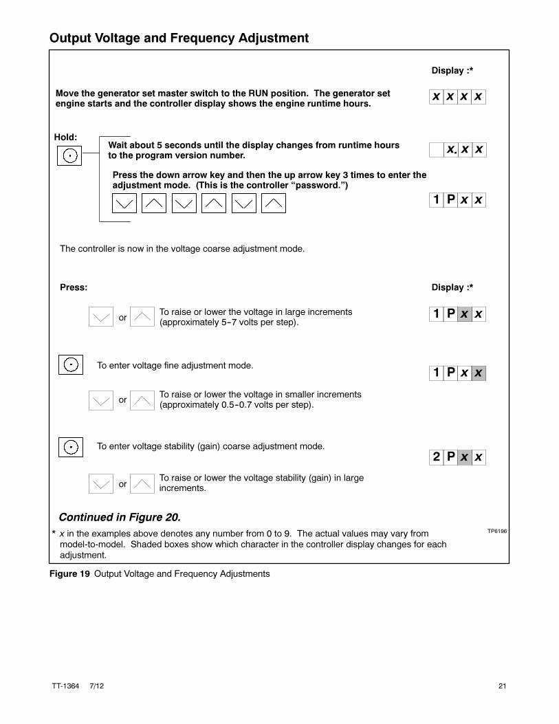
Output Voltage and Frequency Adjustment
TP6196
Move the generator set master switch to the RUN position. The generator setengine starts and the controller display shows the engine runtime hours.
Display :*
or
or
To raise or lower the voltage in large increments(approximately 5--7 volts per step).
To enter voltage fine adjustment mode.
To raise or lower the voltage in smaller increments(approximately 0.5--0.7 volts per step).
To enter voltage stability (gain) coarse adjustment mode.
To raise or lower the voltage stability (gain) in largeincrements.
or
Hold:Wait about 5 seconds until the display changes from runtime hoursto the program version number.
Press the down arrow key and then the up arrow key 3 times to enter theadjustment mode. (This is the controller “password.”)
x x
x x x x
1 P
1 P
2 P
* x in the examples above denotes any number from 0 to 9. The actual values may vary frommodel-to-model. Shaded boxes show which character in the controller display changes for eachadjustment.
x.
The controller is now in the voltage coarse adjustment mode.
Press:
1 P
Continued in Figure 20.
x x
x x
xx
x x
Display :*
Figure 19 Output Voltage and Frequency Adjustments

22 TT-1364 7/12
Display :*
or
To enter engine governor speed coarse adjustment mode.
To raise or lower the engine speed in large increments.
To enter engine governor stability (gain) coarse adjustment mode.
To raise or lower the engine governor stability (gain)in large increments.
To enter engine governor speed fine adjustment mode.
To raise or lower the engine speed in smallerincrements.
To enter engine governor stability (gain) fine adjustment mode.
To raise or lower the engine governor stability (gain)in smaller increments.
4 P
4 P
or
or
or
Continued from Figure 19:
Press:
5 P
5 P
Note: Be sure to save your settings before exiting the adjustmentmode. The controller reverts to the
last saved settings when the master switch is moved to the OFF/RESET position.
* Shaded boxes show which character in the controller display changes for each adjustment. x in theexamples above denotes any number from 0 to 9. The actual values may vary from model-to-model.
S A V ETo enter SAVE mode. Go to Figure 18.
x x
xx
x x
xx
or
To enter volts/Hz adjustment mode.
To raise or lower the volts/Hz: 00=low; 09= high
3 P 0 x
or
To enter voltage stability (gain) fine adjustment mode.
To raise or lower the voltage stability (gain) in smallerincrements.
2 P xx
Figure 20 Output Voltage and Frequency Adjustments, Continued
TT-1364 7/12 23
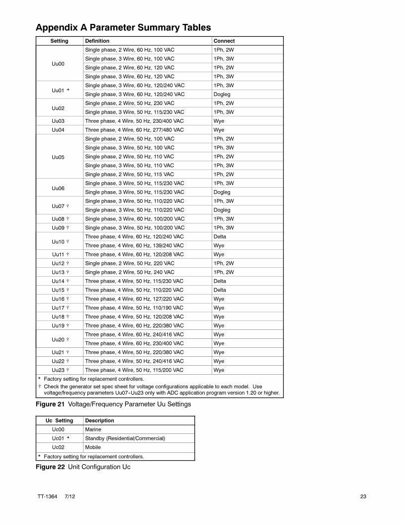
Appendix A Parameter Summary Tables
Setting Definition Connect
Uu00
Single phase, 2 Wire, 60 Hz, 100 VAC 1Ph, 2W
Single phase, 3 Wire, 60 Hz, 100 VAC 1Ph, 3W
Single phase, 2 Wire, 60 Hz, 120 VAC 1Ph, 2W
Single phase, 3 Wire, 60 Hz, 120 VAC 1Ph, 3W
Uu01 *Single phase, 3 Wire, 60 Hz, 120/240 VAC 1Ph, 3W
Single phase, 3 Wire, 60 Hz, 120/240 VAC Dogleg
Uu02Single phase, 2 Wire, 50 Hz, 230 VAC 1Ph, 2W
Single phase, 3 Wire, 50 Hz, 115/230 VAC 1Ph, 3W
Uu03 Three phase, 4 Wire, 50 Hz, 230/400 VAC Wye
Uu04 Three phase, 4 Wire, 60 Hz, 277/480 VAC Wye
Uu05
Single phase, 2 Wire, 50 Hz, 100 VAC 1Ph, 2W
Single phase, 3 Wire, 50 Hz, 100 VAC 1Ph, 3W
Single phase, 2 Wire, 50 Hz, 110 VAC 1Ph, 2W
Single phase, 3 Wire, 50 Hz, 110 VAC 1Ph, 3W
Single phase, 2 Wire, 50 Hz, 115 VAC 1Ph, 2W
Uu06Single phase, 3 Wire, 50 Hz, 115/230 VAC 1Ph, 3W
Single phase, 3 Wire, 50 Hz, 115/230 VAC Dogleg
Uu07 �Single phase, 3 Wire, 50 Hz, 110/220 VAC 1Ph, 3W
Single phase, 3 Wire, 50 Hz, 110/220 VAC Dogleg
Uu08 � Single phase, 3 Wire, 60 Hz, 100/200 VAC 1Ph, 3W
Uu09 � Single phase, 3 Wire, 50 Hz, 100/200 VAC 1Ph, 3W
Uu10 �Three phase, 4 Wire, 60 Hz, 120/240 VAC Delta
Three phase, 4 Wire, 60 Hz, 139/240 VAC Wye
Uu11 � Three phase, 4 Wire, 60 Hz, 120/208 VAC Wye
Uu12 � Single phase, 2 Wire, 50 Hz, 220 VAC 1Ph, 2W
Uu13 � Single phase, 2 Wire, 50 Hz, 240 VAC 1Ph, 2W
Uu14 � Three phase, 4 Wire, 50 Hz, 115/230 VAC Delta
Uu15 � Three phase, 4 Wire, 50 Hz, 110/220 VAC Delta
Uu16 � Three phase, 4 Wire, 60 Hz, 127/220 VAC Wye
Uu17 � Three phase, 4 Wire, 50 Hz, 110/190 VAC Wye
Uu18 � Three phase, 4 Wire, 50 Hz, 120/208 VAC Wye
Uu19 � Three phase, 4 Wire, 60 Hz, 220/380 VAC Wye
Uu20 �Three phase, 4 Wire, 60 Hz, 240/416 VAC Wye
Three phase, 4 Wire, 60 Hz, 230/400 VAC Wye
Uu21 � Three phase, 4 Wire, 50 Hz, 220/380 VAC Wye
Uu22 � Three phase, 4 Wire, 50 Hz, 240/416 VAC Wye
Uu23 � Three phase, 4 Wire, 50 Hz, 115/200 VAC Wye
* Factory setting for replacement controllers.
� Check the generator set spec sheet for voltage configurations applicable to each model. Usevoltage/frequency parameters Uu07--Uu23 only with ADC application program version 1.20 or higher.
Figure 21 Voltage/Frequency Parameter Uu Settings
Uc Setting Description
Uc00 Marine
Uc01 * Standby (Residential/Commercial)
Uc02 Mobile
* Factory setting for replacement controllers.
Figure 22 Unit Configuration Uc

24 TT-1364 7/12
Setting Generator Set Model Applications Engine
Ec00 * 8.5/12RES Kohler CH20, CH740
Ec01 4.5EFOD, 6EOD,6.5EFOZD, 8EOZD
Perkins 403C-07Yanmar 3TNE74
Ec02 7EFOZD, 9EOZD,8.5--17.5EFOZD, 10--20EOZD,9--16.5EFORD/EFORZD, 10--20EORD/EORZD,9--16.5EFORDB/EFORZDB, 10--20EORDB/EORZDB20EORZD/EORZDB Marathon Coach,10/15/20REOD/REOZD,20EFOZD (without preheat option), 23/24EOZD (without preheat option)
Yanmar 3TNV76, 82, 84, 88Yanmar 4TNV84, 88, 98
Ec03 9/11EFG, 10/13/15EG,9/11EFGD, 10/13/15EGD,10/13/15ERG,15RYG, 15RES,
GM 1.6L
Ec04 4/6EFCD, 5/7.3ECD Kawasaki FD501D
Ec05 Not assigned
Ec06 30RYG, 30RES GM 1.6L
Ec07 23--28EFOZD, 28--32EOZD,25--33EFORZD, 30--40EORZD,25--33EFORZDB, 30--40EORZDB
Yanmar 4TNV98
Ec08 12RESM1 Kohler CH20, CH740
Ec09 20EFOZD with preheat option, 23/24EOZD with preheat option Yanmar 4TNV84
Ec10 13/15EGZ, 13/15EGZD with PTO GM 1.6L
Ec11 30RESA, 30REYG GM 1.6L
Ec12 15RESA, 15REYG GM 1.6L
* Factory setting for replacement controllers.
Figure 23 Engine Configuration Parameter Ec
Model Sender Kit Ed
5/7.3ECD
4/6EFCD
None 0
GM45891-KA1 * No Change
6EOD
4.5EFOD
None 1
GM32112-KA1 and -KP1 � 3
GM50552-KA1 * No Change
GM47164-KP1 � No Change
8--32EOZD
6.5--28EFOZD
None 1
GM32112-KA1 and -KP1 * 3
GM50552-KA1 � No Change
10/13/15EG
9/11EFG
13/15EGZ
None 1
GM35299-KA1 and -KP1 * 3
10/13/15EGD
9/11EFGD
13/15EGZD
None 3
10--20EORD/B
10--20EORZD/B
9--16.5EFORD/B
9--16.5EFORZD/B
GM46308-KP1 � No Change
* OP and WT sender kits
� Oil pressure sender kits
� Electronic governor kit
Note: For other models, refer to the parameter setting tables.
Figure 24 Ed settings with Optional Sender Kits
Setting Description
Bt12 * Battery voltage 12 VDC
Bt24 Battery voltage 24 VDC
* Factory setting for replacement controllers.
Figure 25 Battery Voltage Parameter Bt

TT-1364 7/12 25
Cn Setting Description
Cn00 No CAN communication
Cn01 J1939 CAN communication, continuous power to ADC*
Cn02 Smartcraft� gauge for generator set #1 with ECM �
Cn03 Smartcraft� gauge for generator set #2 with ECM �
Cn04 Smartcraft� gauge for generator set #3 with ECM �
Cn05 Smartcraft� gauge for generator set #4 with ECM �
Cn06 J1939 CAN communication, ADC power down after 1 hour for either:*a. Remote start/stop switchb. Automatic transfer switchc: Remote digital gauge GM32337-KP2 with remote start/stop switch
and replacement harness
Cn07 Smartcraft� gauge for generator set #1 without ECM �
Cn08 Smartcraft� 2-inch gauge for generator set #1 with ECM �
Cn09 Smartcraft� 2-inch gauge for generator set #1 without ECM �
* For ADCs with removable power mode jumpers, refer to TT-1439 for power down information.� Smartcraft� settings for ADC code version 2.00 or higher only, for models 5/7.3ECD and 4/6EFCD� Smartcraft� settings for ADC code version 2.20 or higher only.
Figure 26 Communication Parameter Cn
Voltage, Phases
Freq.Hz
Volts,Hz Market
EngineType
DataInputs
BatteryVoltage
CANbusComm.
Uu Uc Ec Ed Bt Cn
120/240 V,1 Ph, 3W 60 1 1 (standby) 0 5 12 0
Figure 27 Factory Settings for Replacement Controllers (Configured for 8.5/12RES)
26 TT-1364 7/12
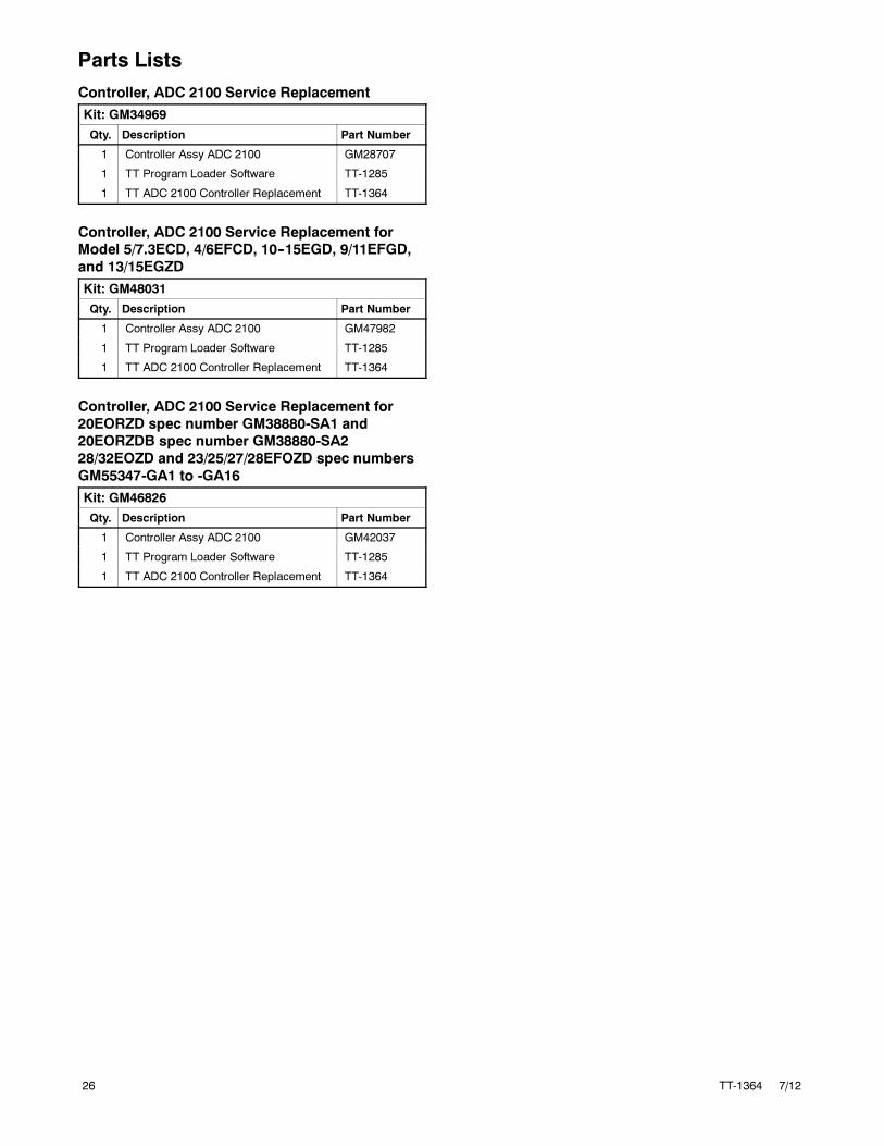
Parts Lists
Controller, ADC 2100 Service Replacement
Kit: GM34969
Qty. Description Part Number
1 Controller Assy ADC 2100 GM28707
1 TT Program Loader Software TT-1285
1 TT ADC 2100 Controller Replacement TT-1364
Controller, ADC 2100 Service Replacement for
Model 5/7.3ECD, 4/6EFCD, 10--15EGD, 9/11EFGD,
and 13/15EGZD
Kit: GM48031
Qty. Description Part Number
1 Controller Assy ADC 2100 GM47982
1 TT Program Loader Software TT-1285
1 TT ADC 2100 Controller Replacement TT-1364
Controller, ADC 2100 Service Replacement for
20EORZD spec number GM38880-SA1 and
20EORZDB spec number GM38880-SA2
28/32EOZD and 23/25/27/28EFOZD spec numbers
GM55347-GA1 to -GA16
Kit: GM46826
Qty. Description Part Number
1 Controller Assy ADC 2100 GM42037
1 TT Program Loader Software TT-1285
1 TT ADC 2100 Controller Replacement TT-1364

TT-1364 7/12 27
Notes

28 TT-1364 7/12
Notes