Embed Size (px)
Citation preview
National Aeronautics and Space Administration
www.nasa.gov 1
Turbine Seal Research at NASA GRC
Presented by
Margaret P. Proctor
NASA Glenn Research Center
Structures and Materials Division
Tribology and Mechanical Components Branch
Contributors:
Bruce M. Steinetz, Irebert R. Delgado, Robert C. Hendricks
NASA GRC
NASA Seals and Secondary Flows Workshop 2011
November 29, 2011
https://ntrs.nasa.gov/search.jsp?R=20150010376 2018-07-12T08:51:06+00:00Z

National Aeronautics and Space Administration
www.nasa.gov 2
Turbomachinery Seal Development Objectives
• Evaluate feasibility of advanced seal concepts and materials of meeting next generation engine speed and temperature requirements.
• Develop seal design and analysis methods.
• Provide a state-of-the-art turbomachinery seal test rig capable of testing seals under known and anticipated design conditions.
• Work with industry to assess and demonstrate performance of their seals prior to test in engine.
National Aeronautics and Space Administration
www.nasa.gov 3
Overall Goals for Turbomachinery Seals
• What do we want? – Long-Life, Low-Leakage, Low-cost Seals
– Experimentally validated design and analysis tools
• What do we hope to gain? Aeronautics
– 2% reduction in specific fuel consumption (SFC) and 0.5 % reduction in direct operating costs (DOC) for gas turbine engines.
Space
– Increased payload capability by reduced propellant and interpropellant flows for liquid propellant rocket engines for space applications.

National Aeronautics and Space Administration
www.nasa.gov 4
Key Accomplishments:
Turbomachinery Seals for Space
National Aeronautics and Space Administration
www.nasa.gov 5
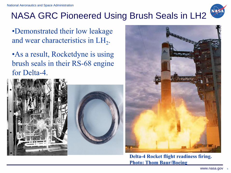
NASA GRC Pioneered Using Brush Seals in LH2
Delta-4 Rocket flight readiness firing.
Photo: Thom Baur/Boeing
•Demonstrated their low leakage
and wear characteristics in LH2.
•As a result, Rocketdyne is using
brush seals in their RS-68 engine
for Delta-4.
National Aeronautics and Space Administration
www.nasa.gov 6
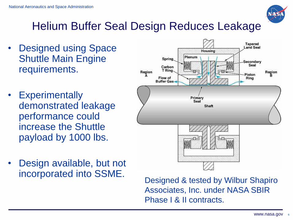
Helium Buffer Seal Design Reduces Leakage
• Designed using Space Shuttle Main Engine requirements.
• Experimentally demonstrated leakage performance could increase the Shuttle payload by 1000 lbs.
• Design available, but not incorporated into SSME.
Designed & tested by Wilbur Shapiro
Associates, Inc. under NASA SBIR
Phase I & II contracts.
National Aeronautics and Space Administration
www.nasa.gov 7
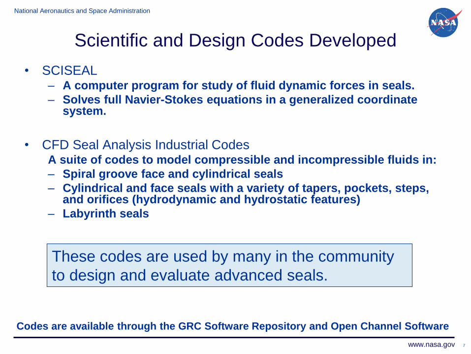
Scientific and Design Codes Developed
• SCISEAL – A computer program for study of fluid dynamic forces in seals.
– Solves full Navier-Stokes equations in a generalized coordinate system.
• CFD Seal Analysis Industrial Codes
A suite of codes to model compressible and incompressible fluids in:
– Spiral groove face and cylindrical seals
– Cylindrical and face seals with a variety of tapers, pockets, steps, and orifices (hydrodynamic and hydrostatic features)
– Labyrinth seals
These codes are used by many in the community
to design and evaluate advanced seals.
Codes are available through the GRC Software Repository and Open Channel Software
National Aeronautics and Space Administration
www.nasa.gov 8
Key Accomplishments:
Turbomachinery Seals for Aeronautics
National Aeronautics and Space Administration
www.nasa.gov 9
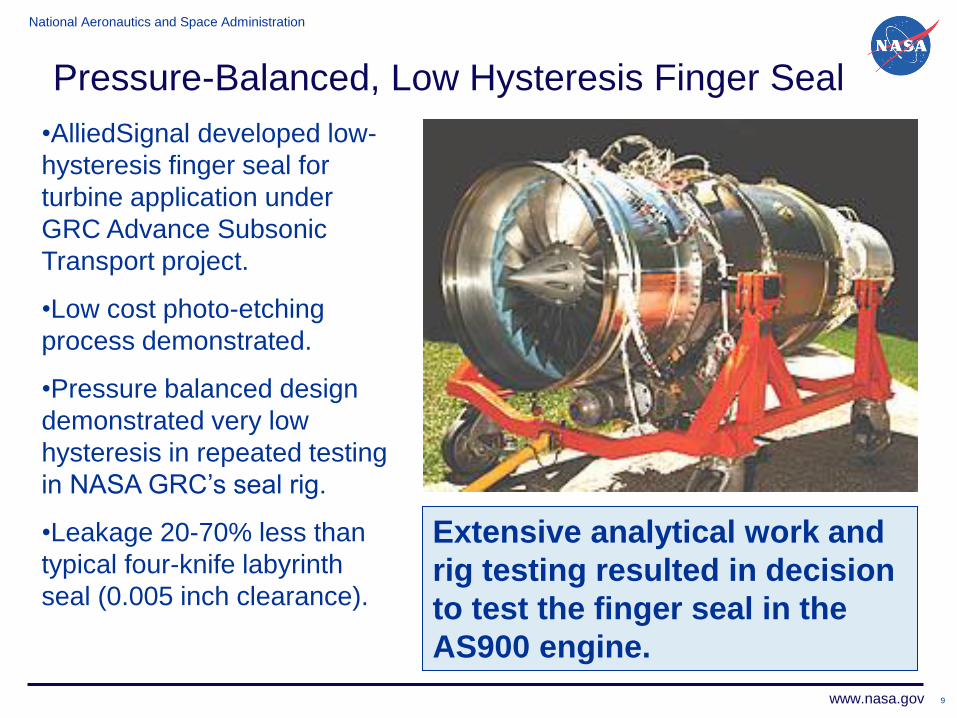
Pressure-Balanced, Low Hysteresis Finger Seal
Extensive analytical work and
rig testing resulted in decision
to test the finger seal in the
AS900 engine.
•AlliedSignal developed low-
hysteresis finger seal for
turbine application under
GRC Advance Subsonic
Transport project.
•Low cost photo-etching
process demonstrated.
•Pressure balanced design
demonstrated very low
hysteresis in repeated testing
in NASA GRC’s seal rig.
•Leakage 20-70% less than
typical four-knife labyrinth
seal (0.005 inch clearance).
National Aeronautics and Space Administration
www.nasa.gov 10
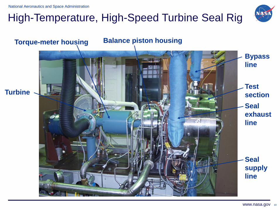
High-Temperature, High-Speed Turbine Seal Rig
Turbine
Torque-meter housing Balance piston housing
Bypass
line
Test
section
Seal
exhaust
line
Seal
supply
line
National Aeronautics and Space Administration
www.nasa.gov 11
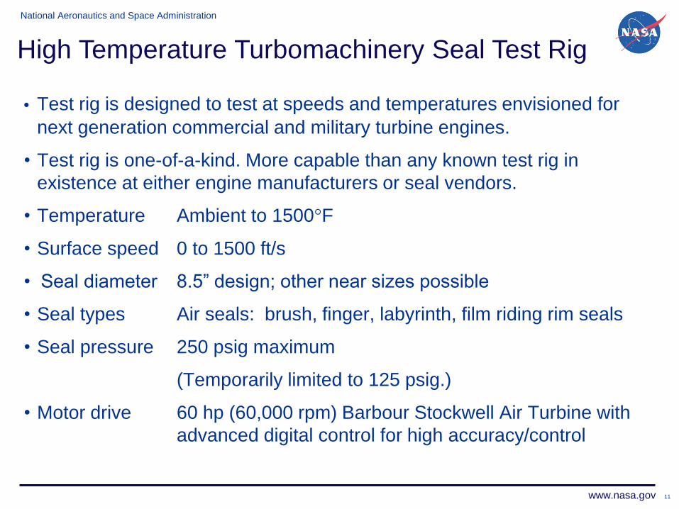
• Test rig is designed to test at speeds and temperatures envisioned for
next generation commercial and military turbine engines.
• Test rig is one-of-a-kind. More capable than any known test rig in
existence at either engine manufacturers or seal vendors.
• Temperature Ambient to 1500°F
• Surface speed 0 to 1500 ft/s
• Seal diameter 8.5” design; other near sizes possible
• Seal types Air seals: brush, finger, labyrinth, film riding rim seals
• Seal pressure 250 psig maximum
(Temporarily limited to 125 psig.)
• Motor drive 60 hp (60,000 rpm) Barbour Stockwell Air Turbine with
advanced digital control for high accuracy/control
High Temperature Turbomachinery Seal Test Rig
National Aeronautics and Space Administration
www.nasa.gov 12
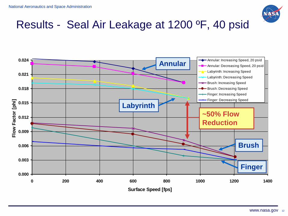
Results - Seal Air Leakage at 1200 ºF, 40 psid
Seal Leakage Comparison at 1200F
0.000
0.003
0.006
0.009
0.012
0.015
0.018
0.021
0.024
0 200 400 600 800 1000 1200 1400
Surface Speed [fps]
Flo
w F
acto
r [p
hi]
Annular: Increasing Speed, 20 psid
Annular: Decreasing Speed, 20 psid
Labyrinth: Increasing Speed
Labyrinth: Decreasing Speed
Brush: Increasing Speed
Brush: Decreasing Speed
Finger: Increasing Speed
Finger: Decreasing Speed
Annular
Labyrinth
Brush
Finger
~50% Flow
Reduction
National Aeronautics and Space Administration
www.nasa.gov 13
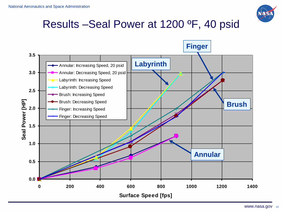
Corrected Seal Power Comparison at 1200F, 40 psid
0.0
0.5
1.0
1.5
2.0
2.5
3.0
3.5
0 200 400 600 800 1000 1200 1400
Surface Speed [fps]
Se
al
Po
we
r [H
P]
Annular: Increasing Speed, 20 psid
Annular: Decreasing Speed, 20 psid
Labyrinth: Increasing Speed
Labyrinth: Decreasing Speed
Brush: Increasing Speed
Brush: Decreasing Speed
Finger: Increasing Speed
Finger: Decreasing Speed
Results –Seal Power at 1200 ºF, 40 psid
Annular
Labyrinth
Finger
Brush
National Aeronautics and Space Administration
www.nasa.gov 14
Current Turbomachinery Seals Research
National Aeronautics and Space Administration
www.nasa.gov 15
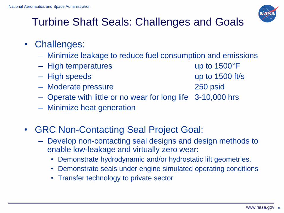
Turbine Shaft Seals: Challenges and Goals
• Challenges: – Minimize leakage to reduce fuel consumption and emissions
– High temperatures up to 1500°F
– High speeds up to 1500 ft/s
– Moderate pressure 250 psid
– Operate with little or no wear for long life 3-10,000 hrs
– Minimize heat generation
• GRC Non-Contacting Seal Project Goal: – Develop non-contacting seal designs and design methods to
enable low-leakage and virtually zero wear:
• Demonstrate hydrodynamic and/or hydrostatic lift geometries.
• Demonstrate seals under engine simulated operating conditions
• Transfer technology to private sector
National Aeronautics and Space Administration
www.nasa.gov 16
Low Leakage, Non-Contacting Brush/Finger
Turbine Seals
• Fundamental Aeronautics Subsonic Fixed Wing Task
• Key Handoffs targeted:
1. Low leakage, non-contacting finger or brush seal with
• Leakage half that of SOA labyrinth seals
• Durability 2x greater than contacting brush or finger seals at
subsonic engine conditions.
2. Experimentally validated design and analysis tools and
methodologies for low leakage non-contacting brush or finger
seals.
National Aeronautics and Space Administration
www.nasa.gov 17
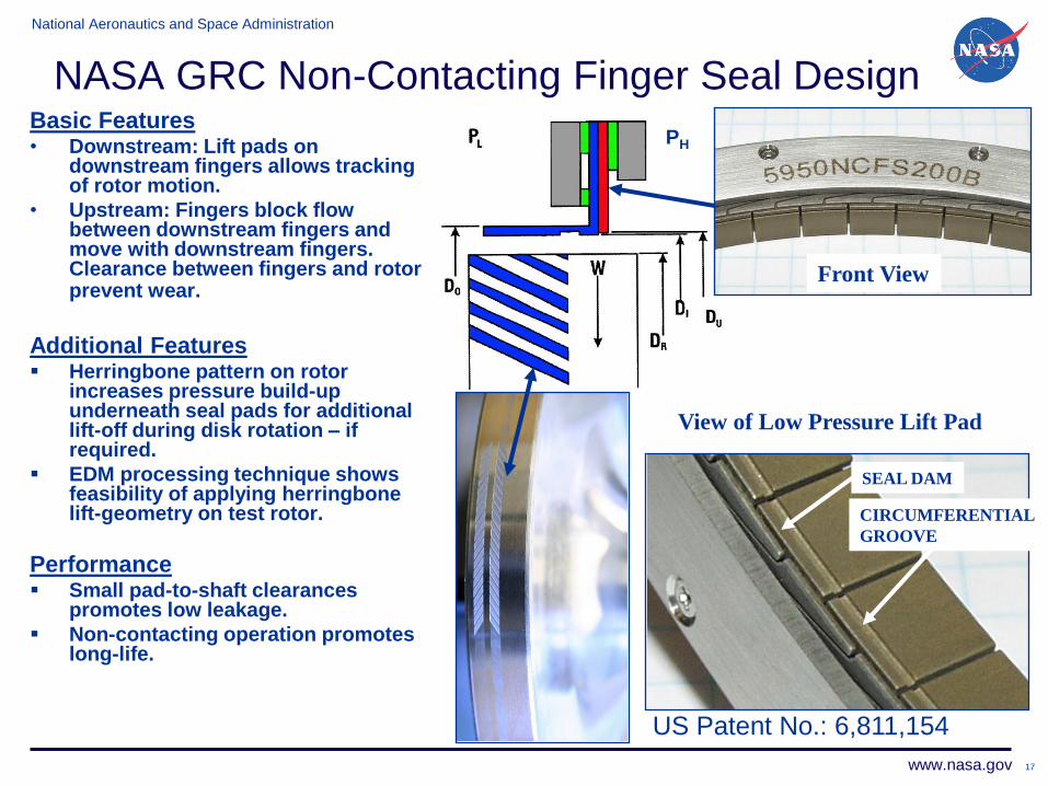
NASA GRC Non-Contacting Finger Seal Design Basic Features • Downstream: Lift pads on
downstream fingers allows tracking of rotor motion.
• Upstream: Fingers block flow between downstream fingers and move with downstream fingers. Clearance between fingers and rotor prevent wear.
Additional Features Herringbone pattern on rotor
increases pressure build-up underneath seal pads for additional lift-off during disk rotation – if required.
EDM processing technique shows feasibility of applying herringbone lift-geometry on test rotor.
Performance Small pad-to-shaft clearances
promotes low leakage.
Non-contacting operation promotes long-life.
SEAL DAM
View of Low Pressure Lift Pad
CIRCUMFERENTIAL
GROOVE
Front View
PH
US Patent No.: 6,811,154
National Aeronautics and Space Administration
www.nasa.gov
Pressure drop across seal, kPa
Flo
w f
ac
tor,
kg
-K1/2/M
pa-m
-s
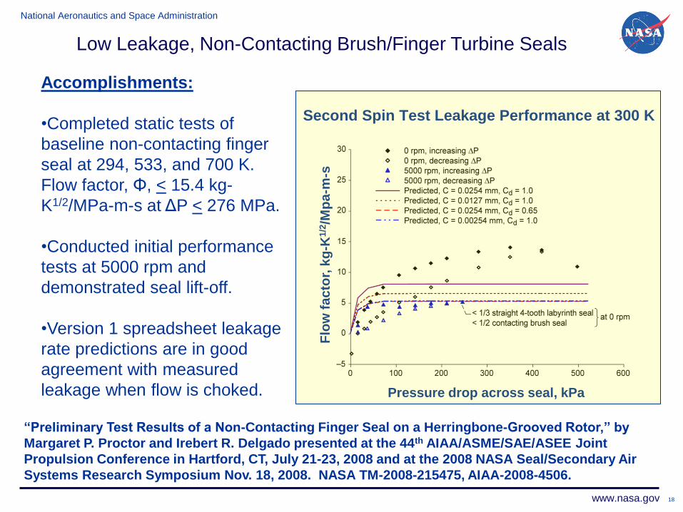
Second Spin Test Leakage Performance at 300 K
18
Accomplishments:
•Completed static tests of
baseline non-contacting finger
seal at 294, 533, and 700 K.
Flow factor, Φ, < 15.4 kg-
K1/2/MPa-m-s at ΔP < 276 MPa.
•Conducted initial performance
tests at 5000 rpm and
demonstrated seal lift-off.
•Version 1 spreadsheet leakage
rate predictions are in good
agreement with measured
leakage when flow is choked.
Low Leakage, Non-Contacting Brush/Finger Turbine Seals
“Preliminary Test Results of a Non-Contacting Finger Seal on a Herringbone-Grooved Rotor,” by
Margaret P. Proctor and Irebert R. Delgado presented at the 44th AIAA/ASME/SAE/ASEE Joint
Propulsion Conference in Hartford, CT, July 21-23, 2008 and at the 2008 NASA Seal/Secondary Air
Systems Research Symposium Nov. 18, 2008. NASA TM-2008-215475, AIAA-2008-4506.
National Aeronautics and Space Administration
www.nasa.gov
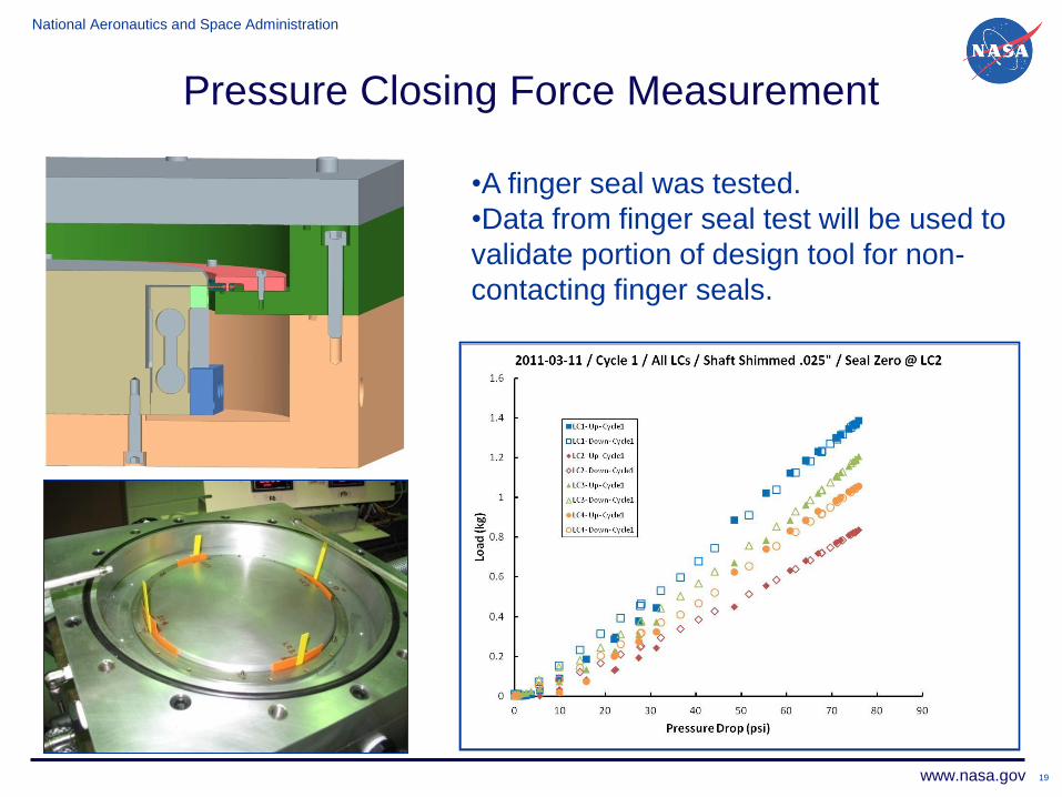
Pressure Closing Force Measurement
19
•A finger seal was tested.
•Data from finger seal test will be used to
validate portion of design tool for non-
contacting finger seals.
National Aeronautics and Space Administration
www.nasa.gov 20
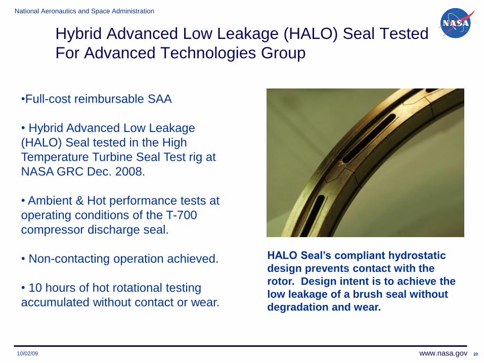
Hybrid Advanced Low Leakage (HALO) Seal Tested
For Advanced Technologies Group
20
•Full-cost reimbursable SAA
• Hybrid Advanced Low Leakage
(HALO) Seal tested in the High
Temperature Turbine Seal Test rig at
NASA GRC Dec. 2008.
• Ambient & Hot performance tests at
operating conditions of the T-700
compressor discharge seal.
• Non-contacting operation achieved.
• 10 hours of hot rotational testing
accumulated without contact or wear.
HALO Seal’s compliant hydrostatic
design prevents contact with the
rotor. Design intent is to achieve the
low leakage of a brush seal without
degradation and wear.
10/02/09
National Aeronautics and Space Administration
www.nasa.gov
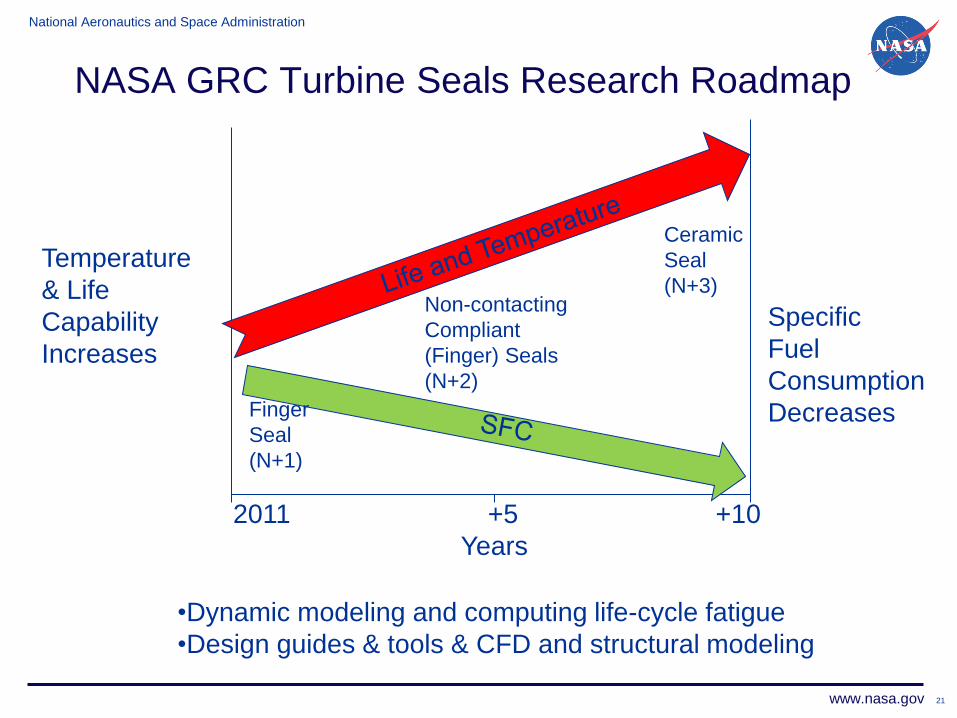
NASA GRC Turbine Seals Research Roadmap
21
2011 +5 +10
Years
Temperature
& Life
Capability
Increases
Specific
Fuel
Consumption
Decreases
Non-contacting
Compliant
(Finger) Seals
(N+2)
Ceramic
Seal
(N+3)
Finger
Seal
(N+1)
•Dynamic modeling and computing life-cycle fatigue
•Design guides & tools & CFD and structural modeling
National Aeronautics and Space Administration
www.nasa.gov
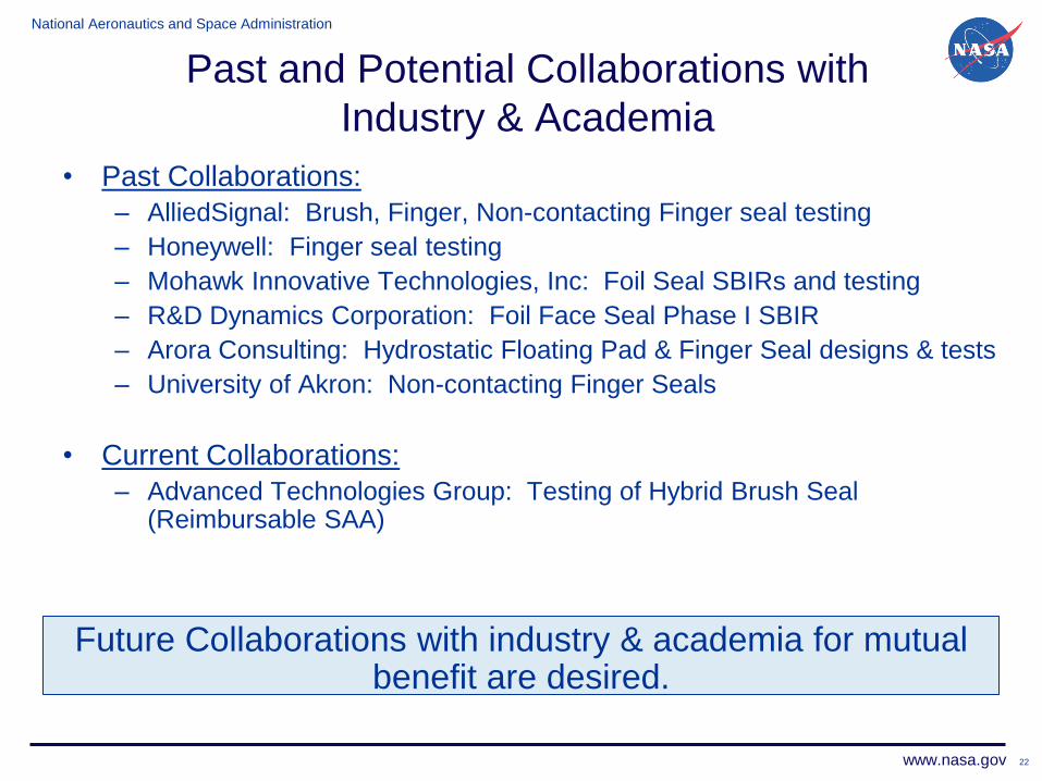
• Past Collaborations:
– AlliedSignal: Brush, Finger, Non-contacting Finger seal testing
– Honeywell: Finger seal testing
– Mohawk Innovative Technologies, Inc: Foil Seal SBIRs and testing
– R&D Dynamics Corporation: Foil Face Seal Phase I SBIR
– Arora Consulting: Hydrostatic Floating Pad & Finger Seal designs & tests
– University of Akron: Non-contacting Finger Seals
• Current Collaborations:
– Advanced Technologies Group: Testing of Hybrid Brush Seal (Reimbursable SAA)
Future Collaborations with industry & academia for mutual benefit are desired.
22
Past and Potential Collaborations with
Industry & Academia
National Aeronautics and Space Administration
www.nasa.gov 23
Summary
• Low-leakage, long-life turbomachinery seals are important to both Space and Aeronautics Missions.
• Increased payload capability
• Decreased specific fuel consumption and emissions
• Decreased direct operating costs
• NASA GRC has a history of significant accomplishments and collaboration with industry and academia in seals research.
• NASA’s unique, state-of-the-art High Temperature, High Speed Turbine Seal Test Facility is an asset to the U.S. Engine / Seal Community.
• Current focus is on developing experimentally validated compliant, non-contacting, high temperature seal designs, analysis, and design methodologies to enable commercialization.