Embed Size (px)
Citation preview
UCF EEL 4914: Senior Design I
Solar Powered Wi-Fi Hotspot
Department of Electrical Engineering and Computer Science
University of Central Florida
Instructor: Dr. Lei Wei
Group 7
Freddy Artigas Electrical Engineer [email protected]
Alan Birmaher Computer Engineer [email protected]
Kevin Diaz Electrical Engineer [email protected]
Aaron Dobo Electrical Engineer [email protected]
i
Table of Contents 1.0.0.0 Executive Summary 1
2.0.0.0 Project Description 2
2.1.0.0 Project Motivation 2
2.2.0.0 Marketing 3
Table 2.2: Marketing Matrix Table 4
2.3.0.0 Project Goal 4
2.4.0.0 Block Diagram 5
Figure 2.4: Block Diagram 5
3.0.0.0 Prologue 6
3.1.0.0 Solar Panels 6
3.2.0.0 Lighting 7
3.3.0.0 Wi-Fi Repeater 7
3.4.0.0 Battery 7
3.5.0.0 Inverter 7
3.6.0.0 Charging Station 7
3.7.0.0 Controller 8
3.8.0.0 Housing Apparatus 8
4.0.0.0 Research 9
4.1.0.0 Solar Panels 9
4.1.1.0 Photovoltaic System 9
4.1.1.1 The History of PV Systems 10
4.1.1.2 Efficiency of PV Systems 10
Table 4.1.1.2: Efficiency of Different PV Technology 11
4.1.1.3. Manufacturing 11
4.1.1.4 The Advantages of PV Systems 12
4.1.1.5 The Disadvantages of PV Systems 12
4.1.2.0 Solar Power System 13
4.1.2.1 Off-Grid (Stand-Alone) 13
4.1.2.2 Grid-Connected 13
Table 4.1.2.2: Comparison of Solar Photovoltaic Systems 14
4.1.3.0 Types of Photovoltaic Systems 14
4.1.3.1 The 12V Photovoltaic System 14
ii
4.1.3.2 The 24V Photovoltaic System 14
4.1.3.3 The 48V Photovoltaic system 14
4.1.4.0 Photovoltaic Cell Technology 15
4.1.4.1 Types of Solar Photovoltaic Cells 15
4.1.4.1a Monocrystalline Cells: 15
Figure 4.1.4.1a: Monocrystalline Solar Panel 16
4.1.4.1b Polycrystalline Cells: 16
Figure 4.1.4.1b: Polycrystalline Solar Panel 17
4.1.4.1c Photovoltaic Thin-Film Solar Panels: 17
Figure 4.1.4.1c: Thin-Film Solar Panel 18
4.1.4.1d Amorphous Silicon (A-Si) 18
Figure 4.1.4.1d: Amorphous Silicon Solar Panel 18
4.1.4.1e Cadmium Tellurium (CdTe) 18
Figure 4.1.4.1e: Cadmium Tellurium Solar Panel 18
4.1.4.1f Copper Indium Gallium Selenide (CIS, CIGS) 18
Figure 4.1.4.1f: Copper Indium Gallium Selenide Solar Panel 19
4.1.4.1g Monocrystalline Vs. Polycrystalline Vs. Thin-Film: 19
Table 4.1.4.1g: Monocrystalline Vs. Polycrystalline Vs. Thin Film 19
4.1.4.2 Solar Panel Selection 20
Table 4.1.4.2 Specification of Bendable Sunpower Solar Panel 20
Figure 4.1.4.2: Bendable Sunpower Solar Panel 21
4.1.4.3 Size of PV Systems 21
4.1.4.4 Panel Configuration 21
4.1.4.4a Configuration in Series 21
4.1.4.4b Configuration in Parallel 22
4.1.4.4c Combination in series and parallel 23
4.1.4.5 Environmental Impact of PV Systems 23
4.2.0.0 Lighting/Illumination 25
4.2.1.0 Different Sources of Illumination 25
4.2.1.0a Torches 25
Figure 4.2.1.0a: Torch 26
4.2.1.0b Incandescent Light Bulbs 26
Figure 4.2.1.0b: Incandescent Light Bulb 27
4.2.1.0c Fluorescent Light Bulbs 27
iii
Figure 4.2.1.0c: Fluorescent Light Bulb 28
4.2.1.0d Halogens 28
Figure 4.2.1.0d: Halogen 29
4.2.1.0e Neon 29
Figure 4.2.1.0e: Neon 29
4.2.1.0f LED 30
Figure 4.2.1.0f-1: LED 1 30
Figure 4.2.1.0f-2: LED 2 30
4.2.1.1 Comparing Light Bulb: Energy 30
Table 4.2.1.1 31
4.2.1.1a Torches 31
4.2.1.1b Incandescent Light Bulbs 31
4.2.1.1c Fluorescent Light Bulbs 31
4.2.1.1d Halogens 32
4.2.1.1e Neon 32
4.2.1.1f LED 32
4.2.1.2 Comparing Light Bulb: Visibility/Distance 32
Table 4.2.1.2: Visibility of Light Bulbs 33
4.2.1.2a Torches 33
4.2.1.2b Incandescent Light Bulbs 33
4.2.1.2c Fluorescent Light Bulbs 33
4.2.1.2d Halogens 33
4.2.1.2e Neon 33
4.2.1.2f LED 33
4.2.1.3 Comparing Light Bulb: Price 34
Table 4.2.1.3: Light Bulb Prices 34
4.2.1.3a Torches 34
4.2.1.3b Incandescent Light Bulbs 35
4.2.1.3c Fluorescent Light Bulbs 35
4.2.1.3d Halogens 35
4.2.1.3e Neon 35
4.2.1.3f LED 35
4.2.1.4 Comparing Light Bulb: Psychological 36
4.2.1.4a Torches 36
iv
4.2.1.4b Incandescent Light Bulbs 36
4.2.1.4c Fluorescent Light Bulbs 36
4.2.1.4d Halogens 37
4.2.1.4e Neon 37
4.2.1.4f LED 37
4.2.1.5 Comparing Light Bulb: Weight & Design 38
4.2.1.5a Torches 38
4.2.1.5b Incandescent Light Bulbs 38
4.2.1.5c Fluorescent Light Bulbs 38
4.2.1.5d Halogens 39
4.2.1.5e Neon 39
4.2.1.5f LED 39
4.2.2.0 Light Bulb Chosen 39
4.2.2.0a Fluorescent Light Bulbs 40
4.2.2.0b Halogens 40
4.2.2.0c LED 41
4.2.2.1 Why……...? 41
4.2.3.0 LEDs 42
Figure 4.2.3.0: LED Light Strip 42
4.2.3.1 LED: Prices 42
4.2.3.2 LED: Sizes/Flexibility 43
4.2.4.0 Implementation of LED in the Umbrella. 43
4.2.4.1 Implementation of LED: Canopy 44
4.2.4.1a Implementation of LED: Canopy Æ Foldable 44
4.2.4.1a Implementation of LED: Canopy Æ Non-Foldable 44
4.2.4.2 Implementation of LED: Ribs 45
4.2.4.2a Implementation of LED: Ribs Æ Foldable 45
4.2.4.2b Implementation of LED: Ribs Æ Non-Foldable 46
4.2.5.0 Other Possible Source of Illumination 46
4.3.0.0 Wi-Fi Amplifier 47
4.3.1.0 Device Connectivity 47
Figure 4.3.1.0: Worldwide Wi-Fi Hotspots [1] 47
4.3.2.0 Network Connectivity Options 47
4.3.2.1 The Requirements 48
v
4.3.2.2 Potential Solutions 49
4.3.3.0 Examination of Wi-Fi Repeater Options 50
4.3.3.1 Wi-Fi Repeater Options 50
4.3.3.2 Comparison 51
4.3.3.3 Conclusion 52
4.3.4.0 Examination of Cellular Hotspot Options 52
4.3.4.1 Cellular Hotspot Options 52
4.3.4.2 Comparison 52
Figure 4.3.4.2: Carrier 4G LTE Speed Comparison [22] 53
4.3.4.3 Conclusion 54
4.3.5.0 Examination of Satellite Hotspot Options 55
4.3.5.1 Satellite Hotspot Options 55
4.3.5.2 Comparison 55
Figure 4.3.5.2: Top 3 Satellite Internet Providers [23] 56
4.3.5.3 Conclusion 56
4.3.6.0 Examination of Solutions 57
4.3.6.1 Option A: Wi-Fi Range Extender 57
4.3.6.2 Option B: Cellular Hotspot 58
Figure 4.3.6.2: AT&T Data Coverage Map USA [8] 59
4.3.6.3 Option C: Satellite Hotspot 60
4.3.6.4 Conclusion 61
4.3.7.0 Device Selection, Installation & Configuration 63
4.3.7.1 Making the Selection 63
4.3.7.2 Potential Issues 63
4.3.7.3 Installation 63
4.3.7.4 Configuration 64
4.3.7.5 Extender Layout & Status Lights 68
4.4.0.0 Battery 70
4.4.1.0 Batteries for Solar Storage 70
4.4.2.0 How a Battery Works 70
Figure 4.4.2.0: The Basic Workings of a Battery 70
4.4.3.0 Different Batteries used for Solar Storage 72
4.4.3.1 Redox Flow Batteries 72
Figure 4.4.3.1: How the Flow battery works 72
vi
4.4.3.2 Lead-Acid Batteries 73
Figure 4.4.3.2: Cell of lead acid battery 74
4.4.3.3 Lithium-Ion Batteries 75
Figure 4.4.3.3: Lithium Ion Battery 75
4.4.4.0 Selecting the Ideal Battery 77
Table 4.4.4.0: Comparing Different Types of Batteries 78
4.4.5.0 Potential Problems with the Battery 78
Figure 4.4.5.0: Example of Faulty Samsung Battery [10] 79
4.4.6.0 Charging the Battery 80
4.5.0.0 Inverters 81
4.5.1.0 Why the Need of an Inverter? 81
4.5.2.0 Inverter Requirements 81
4.5.3.0 Inverter Chosen & Why? 82
4.5.4.0 Design/Specifications of Inverter 83
4.5.4.0a Design: Inverter A 83
Figure 4.5.4.0a: Inverter Design A 83
4.5.4.0b Design: Inverter B 84
Figure 4.5.4.0b: Inverter Design B 84
4.5.5.0 Implementation of Inverter on Umbrella 84
4.5.6.0 Other Possible Inverters 85
4.6.0.0 Charging Station 86
4.6.1.0 Electrical Outlets 86
Figure 4.6.1.0: Polarity Illustration of wall outlet 86
4.6.2.0 Universal Serial Bus 87
4.6.3.0 Picking a Receptacle 88
Table 4.6.3.0: Comparing Different Receptacle Options 88
4.7.0.0 Controllers 90
4.7.1.0 The PWM Controller & the MPPT Controller 90
4.7.1.1 The Pulse Width Modulation Controller 91
Figure 4.7.1.1: PWM Charger Controller 91
4.7.1.2 The Maximum Power Point Tracker Controller 92
Figure 4.7.1.2: MPPT Charger Controller 92
4.7.1.3 PMW Vs. MMPT 92
Table 4.7.1.3: PMW Vs. MPPT Controller 93
vii
5.0.0.0 Design Specification 94
5.1.0.0 Housing Apparatus 94
5.1.0.0a The Base 94
5.1.0.0b The Shaft 94
5.1.0.0b The Rib 95
5.1.0.0c The Canopy 95
5.1.1.0 Base Housing 95
5.1.1.1 Housing: Battery 95
5.1.1.2 Housing: Inverter 96
5.1.2.0 Shaft Housing 96
5.1.2.1 Housing: Charging Station 96
5.1.2.2 Housing: Wires 96
5.1.3.0 Rib Housing 96
5.1.3.1 Housing: LED Lights 96
5.1.4.0 Canopy Housing 97
5.1.4.1 Housing: Solar Panels 97
6.0.0.0 Design Constraints 98
6.1.0.0 Constraints: Solar Panels 98
6.2.0.0 Constraints: LED Lights 98
6.3.0.0 Constraints: Wi-Fi Amplifier 99
6.4.0.0 Constraints: Battery 99
6.5.0.0 Constraints: Inverter 99
6.6.0.0 Constraints: Charging Station 100
6.7.0.0 Constraints: Controller 100
6.8.0.0 Constraints: Housing Apparatus 100
7.0.0.0 Design Implementation 101
7.1.0.0 Implementation: Solar Panels 101
7.2.0.0 Implementation: LED Lights 101
7.3.0.0 Implementation: Wi-Fi Amplifier 102
7.4.0.0 Implementation: Battery 102
7.5.0.0 Implementation: Inverter 102
7.6.0.0 Implementation: Charging Station 103
7.7.0.0 Implementation: Controller 103
7.8.0.0 Implementation: Housing Apparatus 103
viii
8.0.0.0 Project Management 104
8.1.0.0 Management: Solar Panels 104
8.2.0.0 Management: LED Lights 104
8.3.0.0 Management: Wi-Fi Amplifier 104
8.4.0.0 Management: Battery 104
8.5.0.0 Management: Inverter 104
8.6.0.0 Management: Charging Station 104
8.7.0.0 Management: Controller 105
8.8.0.0 Management: Housing Apparatus 105
9.0.0.0 Potential Future 106
10.0.0.0 Epilogue 108
Appendix A 109
References 109
1
1.0.0.0 Executive Summary With the internet becoming one of human's basic needs in life it is no surprise that many different projects and ideas presented in this day in age do their best to find ways to make it more accessible or take advantage of it, like smart devices, and this project is no different than all the other projects that take advantage of the internet. What makes this project very different than all the others is that instead of using the internet this project will try to amplify the internet signals. This will be done by using an umbrella of sorts that will have a Wi-Fi amplifier embedded inside. Now, this Wi-Fi amplifier will need a power source in order for it to function hence the addition of a battery to the umbrella. The next important feature is to add a charging station of sorts in order to charge phones that are using the Wi-Fi capabilities. After, the umbrella having both a battery and Wi-Fi amplifier a problem appears in that eventually the battery will run out of power if it’s powering up the Wi-Fi amplifier and giving a potential charge to phones, tablets, or even laptops. That is where the solar panels got included in order to recharge the battery. For each of the many components there are hundreds to even thousands of options as to which one will be ideal so choosing one just one takes time and effort that is displayed throughout the various sections in this document. However, in order to keep this document as short as possible only a handful of devices will be looked at and compared and the best one that fits the criteria will be picked as the component that will be incorporated in the umbrella. After, finding the best components for the umbrella then comes the testing process. Either a theoretical testing or actual testing of the various components in order to make sure that everything picked works good together and to potentially start the building process of the umbrella. Lastly, what will a project be without giving potential future ideas and implementations? In this part, is where the various different components that were being compared to come into play by allowing Group 7 the ability to play around and create what they believe to be the optimal version of this umbrella?
2
2.0.0.0 Project Description Imagine being able to sit outside and enjoy the great gift Mother Nature has given the human race, which is ultimately getting destroyed by the same humans it was gifted to, and quite possibly the greatest advancement the human race has achieved since the discovery of fire, the internet. Combining two of the greatest things ever experienced, while using the given nature to power it all seems too good to be true, but is it? This project in simple words is a solar powered umbrella with Wi-Fi expanding capabilities while also having the ability to illuminate any given areas if needed. Meaning one can enjoy the great outdoors, while accessing the greatest part about being indoors. Thanks to the seemingly unlimited energy the sun provides, the umbrella and everything inside it will be completely self-sustaining, and provide as minimal an impact on planet earth as it possibly can. With the future seemingly moving away from harmful fossil fuels, and toward more environmentally friendly renewable resources, it is time to jump on the bandwagon as to not be left in its dust, or rather, smog cloud. Currently in 2017 no one truly knows where the current administration of the United States will go with future energy sources. It would make sense to evolve with the times and technology, and move into more renewable. However with the oil, and coal, and natural gas executives pulling the strings of government, it may be up to the American people to innovate opportunities to utilize the gifts provided on a daily basis, that are essentially going toward nothing of substance for the time being. 2.1.0.0 Project Motivation The reasoning behind this project came about when a particular game that swept the nation called Pokémon GO! was released on July 2016. Pokémon GO! game is a mobile exclusive game that required the use of either a mobile phone or tablet that is capable of using the built in features of GPS (Global Positioning System) and mobile data or Wi-Fi in order to play the game. A few weeks after the release of the game picked up momentum in the area of Memorial Mall at UCF (University of Central Florida) was filled with countless of people playing the game whether it was the weekend or late at night despite the next day being a work day for these people catching their favorite Pokémon’s was their top priority. However, there were two major problems that people experienced while playing the game one was how much mobile data the game consumed and the other was how fast the battery from their mobile phones was being drained. Hence, the idea of a device or apparatus that had the capability to amplify the Wi-Fi signal that was provided from the UCF building around Memorial Mall. This apparatus first came in the form of a lamppost that had the capability to amplify the Wi-Fi signal in the area by attaching a Wi-Fi amplifier to the lamppost. While the idea of providing an extra battery charge came much later in the project design because at the time of the game release people were using external battery packs to provide them with the necessary battery charge to play their game without the need to be next to a power outlet.
3
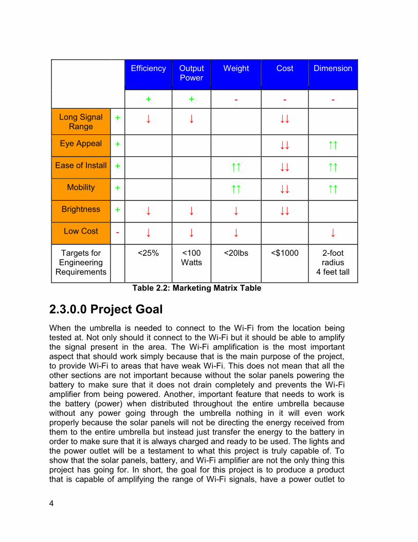
Nonetheless, the idea of charging a mobile device was later implemented because instead of the apparatus being attached onto a lamppost it would instead be integrated into a portable umbrella. Also, the inclusion of the charging feature would now allow the consumer to charge their device because this apparatus will no longer be stuck in a particular area but instead be allowed to move to other areas varying on the consumer's choice of location and whether or not there is a Wi-Fi source the umbrella would still let the consumer charge their mobile electronic devices as needed. Another source, of Wi-Fi is not just regular Wi-Fi but instead just either a phone or some other device that can turn the Wi-Fi amplifier into a mobile hotspot that uses mobile data. This will allow certain electronic appliances other than a phone have the ability to be used despite there being no Wi-Fi signal. Lastly, due to the umbrella being portable that meant that it will be used at any time of the day including the night or in low light areas. So the idea of the lamppost came back around in the form of including some lighting feature within the umbrella. 2.2.0.0 Marketing As presented in Section 2.1.0 the motivation was to allow people to use Wi-Fi outside buildings. This particular concept is still fairly new since over the last decade people have preferred in ‘perfecting’ the indoors instead of trying to better both the indoors and outdoors. However, Group 7’s goal is to try and better the two the same way that Pokémon GO!’s creator Niantic wanted when they created a game that required people to go outside, walk, and interact with other people in the real world instead of through a computer screen. However, this umbrella is not just to play Pokémon GO! Outside without consuming mobile data but instead can be used in many different places that do not have the strongest Wi-Fi signal in certain areas. In practice it must be understood that adding everything comes with a price. Whether they draw in and use more power, or make the product to large or heavy, or just drive up the price to where no one will buy it. The Engineering-Marketing Tradeoff Matrix in Table 2.2 pulls together what can be done in theory, and compares them to what can be done in practice. Below is the tradeoff matrix for the project.
● + = Positive Polarity (Increasing Requirement) ● - = Negative Polarity (Decreasing Requirement) ● ↑↑ = Strong Positive Correlation ● ↑ = Positive Correlation ● ↓↓ = Strong Negative Correlation ● ↓ = Negative Correlation ● Engineering Requirements ● Marketing Requirements
4
Efficiency Output Power
Weight Cost Dimension
+ + - - -
Long Signal Range
+ ↓ ↓ ↓↓
Eye Appeal + ↓↓ ↑↑
Ease of Install + ↑↑ ↓↓ ↑↑
Mobility + ↑↑ ↓↓ ↑↑
Brightness + ↓ ↓ ↓ ↓↓
Low Cost - ↓ ↓ ↓ ↓
Targets for Engineering
Requirements
<25% <100 Watts
<20lbs <$1000 2-foot radius
4 feet tall
Table 2.2: Marketing Matrix Table 2.3.0.0 Project Goal When the umbrella is needed to connect to the Wi-Fi from the location being tested at. Not only should it connect to the Wi-Fi but it should be able to amplify the signal present in the area. The Wi-Fi amplification is the most important aspect that should work simply because that is the main purpose of the project, to provide Wi-Fi to areas that have weak Wi-Fi. This does not mean that all the other sections are not important because without the solar panels powering the battery to make sure that it does not drain completely and prevents the Wi-Fi amplifier from being powered. Another, important feature that needs to work is the battery (power) when distributed throughout the entire umbrella because without any power going through the umbrella nothing in it will even work properly because the solar panels will not be directing the energy received from them to the entire umbrella but instead just transfer the energy to the battery in order to make sure that it is always charged and ready to be used. The lights and the power outlet will be a testament to what this project is truly capable of. To show that the solar panels, battery, and Wi-Fi amplifier are not the only thing this project has going for. In short, the goal for this project is to produce a product that is capable of amplifying the range of Wi-Fi signals, have a power outlet to
5
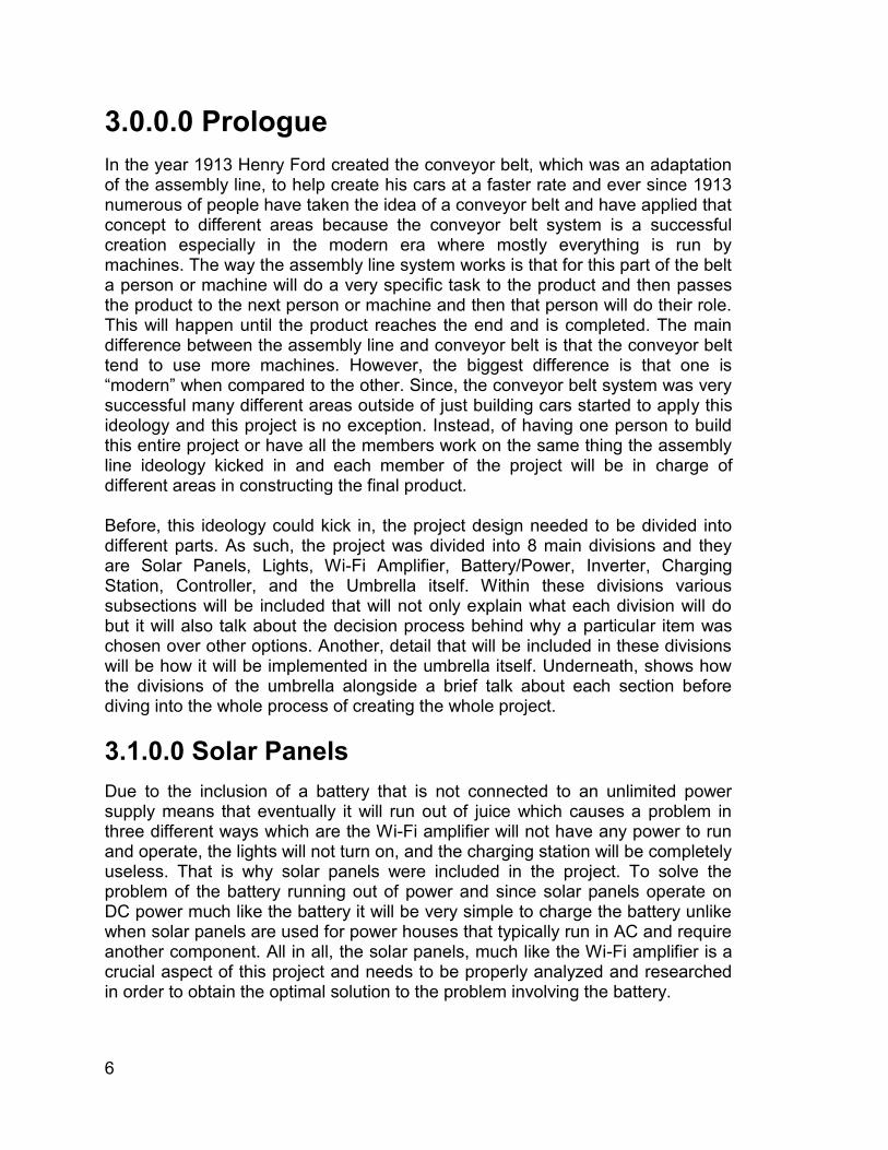
charge mobile devices such as phones and tablets, and provide some form of illumination in the instance the device is used either at non-lighted areas or low lighted areas. 2.4.0.0 Block Diagram
Figure 2.4: Block Diagram
As seen from the above block diagram in Figure 2.4, the solar panel will draw in the sunlight, and the power created will be used to charge the rechargeable battery backup. The battery backup will then be used to power each of the branched off components. The photovoltaic solar panel will come with a controller connected to the battery backup as to prevent from overcharging, and monitor the power generated and transported to the battery. In-between the battery and the charging station an inverter will be placed in order to convert the DC from the battery into the AC needed for the charging station. It is necessary to remember that getting all of the components to work in unison will be no easy task. The battery will only output so much power, and that power must be split between everything that needs it. This is a very simple yet effective way to ensure each member has a job assignment, and to give a general idea on the functionality of the project. The color codes refer to who will do which part. The solar panels will be Freddy Artigas, Wi-Fi amplifier will be Alan Birmaher, Kevin Diaz will do the Lights, and Aaron Dobo will be in charge of the backup, as well as the charging station.
6
3.0.0.0 Prologue In the year 1913 Henry Ford created the conveyor belt, which was an adaptation of the assembly line, to help create his cars at a faster rate and ever since 1913 numerous of people have taken the idea of a conveyor belt and have applied that concept to different areas because the conveyor belt system is a successful creation especially in the modern era where mostly everything is run by machines. The way the assembly line system works is that for this part of the belt a person or machine will do a very specific task to the product and then passes the product to the next person or machine and then that person will do their role. This will happen until the product reaches the end and is completed. The main difference between the assembly line and conveyor belt is that the conveyor belt tend to use more machines. However, the biggest difference is that one is “modern” when compared to the other. Since, the conveyor belt system was very successful many different areas outside of just building cars started to apply this ideology and this project is no exception. Instead, of having one person to build this entire project or have all the members work on the same thing the assembly line ideology kicked in and each member of the project will be in charge of different areas in constructing the final product. Before, this ideology could kick in, the project design needed to be divided into different parts. As such, the project was divided into 8 main divisions and they are Solar Panels, Lights, Wi-Fi Amplifier, Battery/Power, Inverter, Charging Station, Controller, and the Umbrella itself. Within these divisions various subsections will be included that will not only explain what each division will do but it will also talk about the decision process behind why a particular item was chosen over other options. Another, detail that will be included in these divisions will be how it will be implemented in the umbrella itself. Underneath, shows how the divisions of the umbrella alongside a brief talk about each section before diving into the whole process of creating the whole project. 3.1.0.0 Solar Panels Due to the inclusion of a battery that is not connected to an unlimited power supply means that eventually it will run out of juice which causes a problem in three different ways which are the Wi-Fi amplifier will not have any power to run and operate, the lights will not turn on, and the charging station will be completely useless. That is why solar panels were included in the project. To solve the problem of the battery running out of power and since solar panels operate on DC power much like the battery it will be very simple to charge the battery unlike when solar panels are used for power houses that typically run in AC and require another component. All in all, the solar panels, much like the Wi-Fi amplifier is a crucial aspect of this project and needs to be properly analyzed and researched in order to obtain the optimal solution to the problem involving the battery.
7
3.2.0.0 Lighting Right underneath the canopy of the umbrella will be a form of illumination because this umbrella will not always be used during the daytime or in places with enough illumination that allows the person to see the area around them. An ideal light source will be small, energy efficient, capable of fitting in any area of the umbrella, and have the ability to fold in the instance it is inserted in an area that requires the umbrella to be folded. As such, various different criteria must be met before a light source for this project is chosen with the most important feature being energy efficient due to this entire project being portable and not being connected to a potential unlimited power source. 3.3.0.0 Wi-Fi Repeater The Wi-Fi repeater creates a wireless network in the area of the device placement which solves the issues of “dead zones” that are often seen in outdoor areas where indoor wireless routers do not reach. This is a huge part of the functionality of the device and is one of its largest selling points. Many possible solutions for this were explored but ultimately a Wi-Fi repeater application seemed to be the most logical. 3.4.0.0 Battery The solar panels do not connect directly to the devices for power. The solar panels will have to be connected to a rechargeable battery backup which in turn powers any device within. The initial idea is to put a 12 volt battery that will have enough juice in it to last through the night and will not die out while in use. A great example would be the little solar lights some people place along their sidewalks, or in their gardens. It collects energy from the sun during the day, while lighting up the area all night long. It will be similar to that, but rather on a larger, more powerful scale. 3.5.0.0 Inverter Due to both the Wi-Fi amplifier and charging station being implemented to the umbrella and both the battery and solar panels working in DC while all electronic appliances work in AC an inverter needs to be incorporated in the umbrella in order for the electronic devices that are connected to the charging station to get some charge or to work properly. 3.6.0.0 Charging Station In the grand scheme of things, the devices we use every day is still relatively new. The batteries are not at their peak efficiency, or being used at their full
8
potential leading to premature dead batteries. In order to avoid this, an outlet with built in USB chargers will be placed to allow for device charging. 3.7.0.0 Controller Anytime a solar panel is part of a project a controller of sorts needs to be squeezed inside because without the solar panel will not operate properly. That is why an optimal controller needs to be picked that suits best this project. Similar to all the other various feature that are a part of this project the controller needs to be small, cost efficient, and functions to its fullest. The reason why the controller needs to always function to its fullest it's because it is a huge component regarding the solar panels and since the solar panels are what will keep this project ‘alive’ for various or long uses a proper controller needs to embedded. 3.8.0.0 Housing Apparatus The key is to get everything working together, and they will all need a house for them all to live and work with one another. The key is for the housing unit to be large enough to fit the necessary components, but not too large as to be impossible to move and work with. Because it will be home to many of the electronic parts, it must not be closed in, as to allow any heat generated may escape and not overheat any of the electronics.
9
4.0.0.0 Research In Chapter 3 a simple representation of each different division of the apparatus was described. However, Chapter 4 is going to elaborate on all of these sections accordingly. Showing various different components for each division, comparing them, and ultimately forming a formidable conclusion as to which part will suit the umbrella best. 4.1.0.0 Solar Panels 4.1.1.0 Photovoltaic System A photovoltaic system (PV), is a power system designed to supply usable solar power throughout of photovoltaics. Solar panels offer the ability to generate clean and accessible electricity. The solar systems are composed of photovoltaic cells, which are devices that directly convert solar energy into electricity without producing any contamination. Photovoltaic systems are installed in locations that already have electricity through the power grid, but want to reduce and eventually eliminate their electricity costs, and also the cheapest and most viable option in situations where the electricity grid is far away. Moreover, solar photovoltaic cells are semiconductor devices and the majority of today's largest producers are mainly made of crystalline silicon as a semiconductor material. Solar photovoltaic modules, which are a result of a combination of photovoltaic cells to increase their power, are highly reliable, durable and low noise devices to produce electricity. The sun is the only resource that is required for the operation of PV systems, and its energy is almost inexhaustible. The fuel for the photovoltaic cell is free. Photovoltaic systems produce no noise, there are no moving parts and they do not emit pollutants into the environment. Also, they have a lifetime of more than thirty years and is one of the most reliable semiconductor products. Most solar cells are produced from silicon, which is non‐ toxic and is found in abundance around the world. The PV systems come with different type of shapes and sizes. Choosing the right type requires specifications to provide a variety of applications, economics aspects, and electrical aspects based on the measurement of the PV. The systems range from small, rooftop-mounted or building-integrated systems with capacities from a few to several tens of kilowatts, to large utility scale power stations of hundreds of megawatts. Most PV systems are grid-connected, while off-grid or stand-alone systems only account for a small portion of the market. The decision of a larger solar panel versus a small solar panel depends on of the application given. Furthermore, to find the suitable solar panels depends on many factors and categories. There are many categories in the market today, but for this project, the two main
10
categories of solar systems that can be installed are The Off-Grid (Stand-Alone) Solar Power System, and The Grid-Connected Solar Power System. Each of these PV systems can provide a great benefit as well as their own advantage and disadvantage depending on the application utilized. 4.1.1.1 The History of PV Systems The term photovoltaic comes from the Greek Phos, that means "light" and voltaic that comes from Electricity, in honor of the Italian scientist Alessandro Volta. The term photovoltaic began to be used in England from the year 1849. The effect Photovoltaic was first recognized in 1839 by the French physicist Becquerel, but the first solar cell was not built until 1883. Its author was Charles Fritts, who covered a sample of semiconductor selenium with a gold leaf to form the joint. This primitive device had an efficiency of only 1%. Russel Ohl, patented the modern solar cell in 1946, although Sven Berglund had previously patented a method that tried to increase the capacity of photosensitive cells. The modern era of technology of solar power did not arrive until the year 1954 when the Bell laboratories accidentally discovered that the semiconductors of silicon doped with certain impurities, were very sensitive to the light. These advances contributed to the manufacture of the first commercial solar cell. The first spacecraft to use solar panels was the North American satellite Vanguard. It was a crucial development that stimulated research by some governments and that promoted the improvement of the solar panels. Furthermore, the first solar cell with an ethereal structure of gallium arsenide (GaAs) and highly efficient was developed in the extinguished USSR by Zhores Alferov. The first company to manufacture solar panels in industrial quantities, from GaAs, with an Air Mass Zero efficiency was the Applied Solar Energy Corporation (ASEC). Moreover, in an accidental manner, the dual cell was produced by ASEC in 1989. In addition, ASEC developed the first double-junction in The United States, with an efficiency of approximately 20%. These cells do not use the Germanium as the second cell but use a cell based on GaAs with different types of doping. 4.1.1.2 Efficiency of PV Systems The efficiency is the most common used parameter that compare the performance of one photovoltaic cell to another. Besides, efficiency is defined as the energy ratio of output from the solar cell to input energy from the sun. Also, the efficiency depends on the spectrum and intensity of the sunlight and the temperature of the photovoltaic cell. Therefore, the conditions under which efficiency is measured must be carefully controlled to compare the performance of one device to another device. Also, photovoltaic efficiency denotes to the portion of energy in the form of sunlight that can be converted via photovoltaics into electricity. Likewise, PV
11
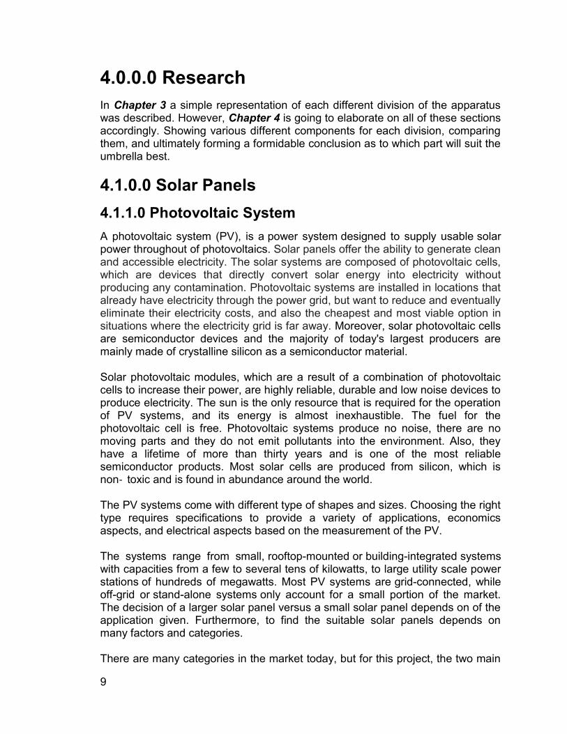
efficiency refers to how efficiently a photovoltaic cell or solar module produces electricity. Next, photovoltaic efficiency designates the conductivity of solar panels and the percentage of radiation energy converted in electrical energy. Moreover, the efficiency of the PV used in a photovoltaic system with latitude and climate, determines the annual energy output of the system. The conversion efficiency of PV cells is the solar energy shining on a PV device that is converted in usable electricity. In addition, this conversion efficiency fundamental goal of investigation is to helps make PV technologies competitive with conventional energy sources. Numerous issues affect a cell conversion efficiency value, including its, thermodynamic efficiency, conduction efficiency values, charge carrier separation efficiency and reflectance efficiency. Furthermore, these parameters sometimes are difficult to measure directly. Also, not all the sunlight that reaches a cell is converted into electricity. Many factors in solar cell design limits the ability to convert the sunlight it receives. Having these factors in mind is how higher efficiencies can be accomplished.
PV cells Efficiency in percentage GalnP/GaAs/GalnNAs cell 43%
Silicon Crystalline 22% Gallium Arsenide Crystalline
(GaAs) 21%
Silicon Thin-Film 9% Table 4.1.1.2: Efficiency of Different PV Technology
4.1.1.3. Manufacturing For its construction, a silicon rod without crystalline amorphous structure is obtained from the common sand. By an electronic process, which also eliminates the impurities, the amorphous silicon bar is transformed into a monocrystalline structure, which has characteristics of electrical insulation, being formed by a network of highly stable atomic bonds. Then, with the material totally absent from impurities, it is cut into wafers. Furthermore, the wafers are then photographed in cells with positive and negative polarities. The positive polarity is achieved by introducing holes, that is, impurities that are composed of atoms that in their layer that have only three electrons. On the other hand, in the negative zone a process similar to the positive zone is followed, but in this case the impurities that are injected are atoms that in their layer that have five electrons in the structure of glass, so it is said to have negative charge. Finally, the set of both materials positive and negative form a diode, the characteristic of the diode is letting the electric current pass in one direction, and although the diodes are used to rectify the electric current allowing light to enter the crystal structure, and the movement of electrons inside the
12
material, that is why this diode is called photoelectric cell. 4.1.1.4 The Advantages of PV Systems Photovoltaic solar energy is one of the most promising sources of energy and renewable energy in the world. Compared to non-renewable sources, the advantages are clear: it is not a contaminant and does not require a lot of maintenance. Does not generate waste. Does not require extensive installation to operate. No noise is totally silent. Does not consume fossil fuels. It is an inexhaustible source. Offers a high reliability and excellent operational availability. In short, photovoltaic energy is generated directly from the sun. Photovoltaic systems they do not have moving parts, therefore they do not require maintenance and their cells last decades. Resist extreme weather conditions: hail, wind, temperature, humidity. They have a long life (Solar panels last about 20 to 30 years). Can be installed in rural areas development of own technologies. Can be used in low-consumption places and in homes located in rural areas where the general power grid does not reach. There is no dependence on fuel producing countries. Power can be increased by incorporating new photovoltaic modules. 4.1.1.5 The Disadvantages of PV Systems This system of energy generation, it is not so much the origin of energy which is the Sun, which has reserves that exceed our needs, nor does the raw material from where the silicon is extracted, which consists of common sand very abundant in nature: it is treated of the technique of construction and manufacture of photovoltaic modules that is complex and expensive. Solar energy has intermittency issues, thus not shining at night but also during daytime there may be the cloudy or rainy weather. Furthermore, for a continuous supply of electric power, especially for on-grid connections, Photovoltaic panels require additional equipment (inverters) to convert (DC) direct electricity to (AC) alternating electricity in order to be used on the power network. But, also storage batteries; thus increasing the investment cost for PV panels considerably. It is an energy of difficult storage. It is not economically competitive with other current energies. Variable production according to the climatology of the place and time of the year. In the case of land-mounted PV panel installations, they require relatively large areas for deployment. The land space is committed for this purpose for a period of 12-15 years or longer. The PV panels are fragile and can be damaged relatively easily, they have no considerable maintenance or operating costs. In addition, insurance costs are of fundamental importance to safeguard a PV investment.
13
4.1.2.0 Solar Power System 4.1.2.1 Off-Grid (Stand-Alone) Solar photovoltaic honeycombs are used to convert solar energy into electricity, except that in this case all that generated energy is stored in a bank of batteries. Since the system does not require any connection to the utility line, the installation becomes more simply and it can be a proper choice for some eco-friendly applications which do not require any power supplied from local utility. Mostly, this system is preferred to be placed where the utility pole or grid cannot reach too. These types of systems are very common in rural areas or remote from cities, where the power grid does not reach. One of the main factors making the off-grid system preferable is the independent characteristic. Since the system is not installed on a certain fixed location, it can be mounted on any place for its functionality purpose. The system is completely independent and thanks to which you store the energy you can use it in the evenings and during the cloudy days. For example, power your entertainment center or a small shed that you have in the garden, light poles and more. Moreover, most of the time, rechargeable backup batteries are always viewed as a better solution for power storage system than any other system. Usually, the backup power batteries have a wide range of selections based on the demand of the loads and the budget for the system. 4.1.2.2 Grid-Connected They are interconnected to the electricity grid. In other words, all the energy generated by the solar panels is injected directly into the local grid and they operate in parallel with the grid. In most cases, for interconnected systems, you must make a contract with your local electricity company that verifies that your entire system complies with the regulations since the energy you generate sends it to the national grid and it is fundamental to guarantee its quality. Since the system is tied to the grid, it provides the dual solution to both problems in powers, power outage and extra power supplied. The extra power supplied from the solar panel can be directly transferred into the grid when the loads are over supplied, and with this solution, the potential damage to the device due to overpowering supplied can be reduced and no unused power will be wasted. Furthermore, for the power outage, the load demand will be supplied the power from the utility grid if the power from the solar panels are not generated enough for the application to operate. These systems are sometimes cheaper because you do not need a battery bank, which is sometimes the most expensive devices in the isolated system and those that require the most maintenance. The batteries are not needed because most of the power flow actions take place between the grid and the loads. The cost of
14
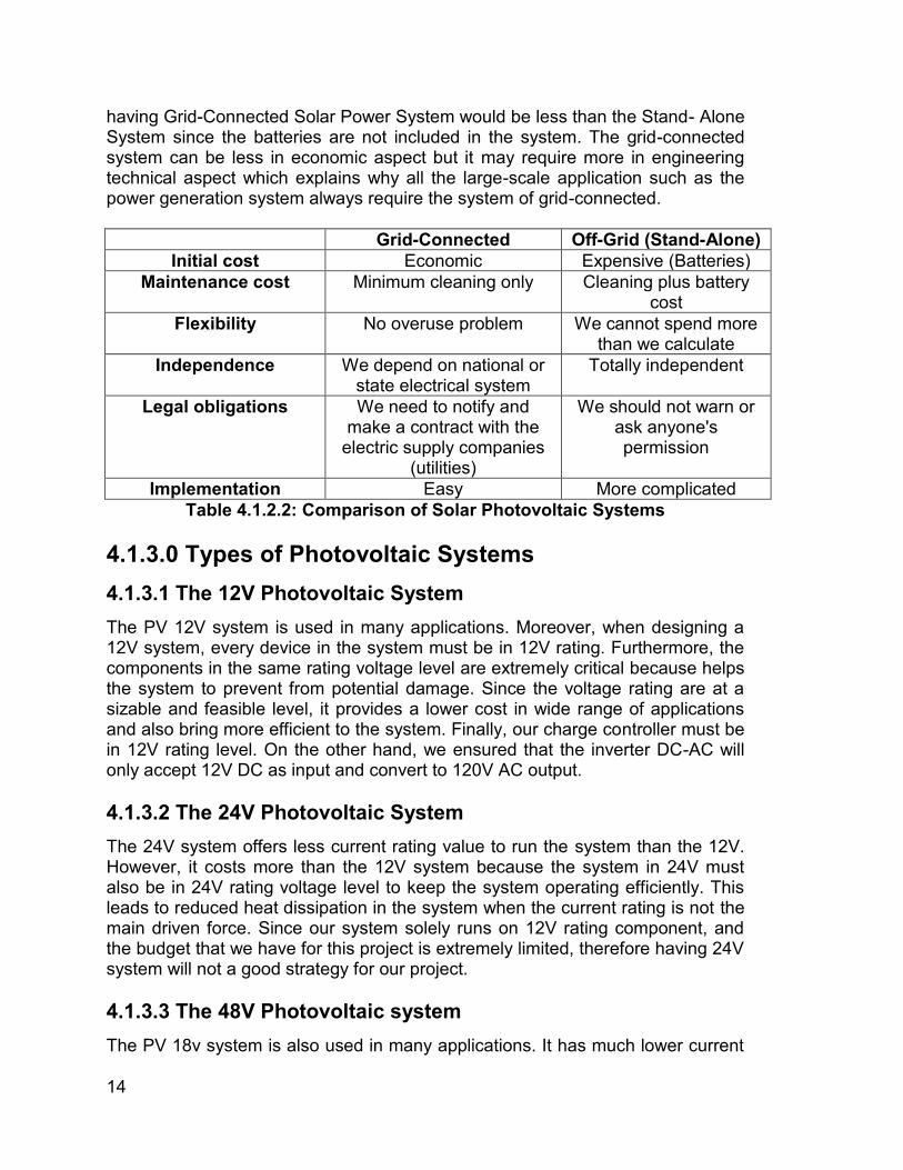
having Grid-Connected Solar Power System would be less than the Stand- Alone System since the batteries are not included in the system. The grid-connected system can be less in economic aspect but it may require more in engineering technical aspect which explains why all the large-scale application such as the power generation system always require the system of grid-connected.
Grid-Connected Off-Grid (Stand-Alone) Initial cost Economic Expensive (Batteries)
Maintenance cost Minimum cleaning only Cleaning plus battery cost
Flexibility No overuse problem We cannot spend more than we calculate
Independence We depend on national or state electrical system
Totally independent
Legal obligations We need to notify and make a contract with the
electric supply companies (utilities)
We should not warn or ask anyone's permission
Implementation Easy More complicated Table 4.1.2.2: Comparison of Solar Photovoltaic Systems
4.1.3.0 Types of Photovoltaic Systems 4.1.3.1 The 12V Photovoltaic System The PV 12V system is used in many applications. Moreover, when designing a 12V system, every device in the system must be in 12V rating. Furthermore, the components in the same rating voltage level are extremely critical because helps the system to prevent from potential damage. Since the voltage rating are at a sizable and feasible level, it provides a lower cost in wide range of applications and also bring more efficient to the system. Finally, our charge controller must be in 12V rating level. On the other hand, we ensured that the inverter DC-AC will only accept 12V DC as input and convert to 120V AC output. 4.1.3.2 The 24V Photovoltaic System The 24V system offers less current rating value to run the system than the 12V. However, it costs more than the 12V system because the system in 24V must also be in 24V rating voltage level to keep the system operating efficiently. This leads to reduced heat dissipation in the system when the current rating is not the main driven force. Since our system solely runs on 12V rating component, and the budget that we have for this project is extremely limited, therefore having 24V system will not a good strategy for our project. 4.1.3.3 The 48V Photovoltaic system The PV 18v system is also used in many applications. It has much lower current
15
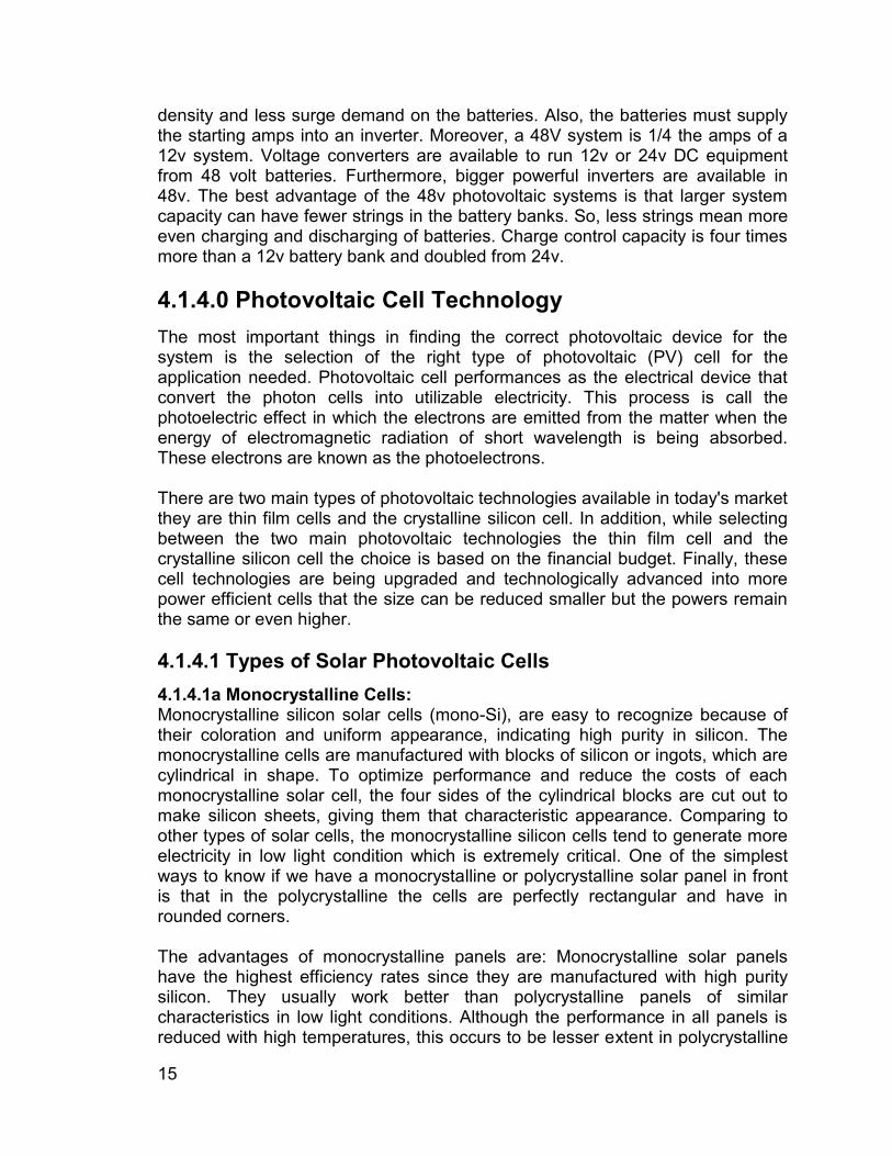
density and less surge demand on the batteries. Also, the batteries must supply the starting amps into an inverter. Moreover, a 48V system is 1/4 the amps of a 12v system. Voltage converters are available to run 12v or 24v DC equipment from 48 volt batteries. Furthermore, bigger powerful inverters are available in 48v. The best advantage of the 48v photovoltaic systems is that larger system capacity can have fewer strings in the battery banks. So, less strings mean more even charging and discharging of batteries. Charge control capacity is four times more than a 12v battery bank and doubled from 24v. 4.1.4.0 Photovoltaic Cell Technology The most important things in finding the correct photovoltaic device for the system is the selection of the right type of photovoltaic (PV) cell for the application needed. Photovoltaic cell performances as the electrical device that convert the photon cells into utilizable electricity. This process is call the photoelectric effect in which the electrons are emitted from the matter when the energy of electromagnetic radiation of short wavelength is being absorbed. These electrons are known as the photoelectrons. There are two main types of photovoltaic technologies available in today's market they are thin film cells and the crystalline silicon cell. In addition, while selecting between the two main photovoltaic technologies the thin film cell and the crystalline silicon cell the choice is based on the financial budget. Finally, these cell technologies are being upgraded and technologically advanced into more power efficient cells that the size can be reduced smaller but the powers remain the same or even higher. 4.1.4.1 Types of Solar Photovoltaic Cells 4.1.4.1a Monocrystalline Cells: Monocrystalline silicon solar cells (mono-Si), are easy to recognize because of their coloration and uniform appearance, indicating high purity in silicon. The monocrystalline cells are manufactured with blocks of silicon or ingots, which are cylindrical in shape. To optimize performance and reduce the costs of each monocrystalline solar cell, the four sides of the cylindrical blocks are cut out to make silicon sheets, giving them that characteristic appearance. Comparing to other types of solar cells, the monocrystalline silicon cells tend to generate more electricity in low light condition which is extremely critical. One of the simplest ways to know if we have a monocrystalline or polycrystalline solar panel in front is that in the polycrystalline the cells are perfectly rectangular and have in rounded corners. The advantages of monocrystalline panels are: Monocrystalline solar panels have the highest efficiency rates since they are manufactured with high purity silicon. They usually work better than polycrystalline panels of similar characteristics in low light conditions. Although the performance in all panels is reduced with high temperatures, this occurs to be lesser extent in polycrystalline
16
than in monocrystalline. The efficiency of these panels is above 14% and for some brands, it exceeds 20%. The life of the monocrystalline panels is longer. In fact, many manufacturers offer warranties of up to 25 years. The disadvantages of monocrystalline panels are: They're more expensive. By valuing the economic aspect, for domestic use, it is more advantageous to use polycrystalline or even thin-film panels. If you decide to put monocrystalline panels but you think they may be shaded at some point, it is best to use solar micro inverters instead of a chain or central inverters. Micro inverters ensure that the entire solar installation is not affected by only one affected panel. If the panel is partially covered by a shadow, dirt or snow, the entire circuit may be damaged. The Czochralski process is the one used for the manufacture of monocrystalline silicon. As a result, cylindrical blocks are obtained. Furthermore, four sides are cut out to make the silicon sheets, and a lot of silicon is wasted in the process.
Figure 4.1.4.1a: Monocrystalline Solar Panel
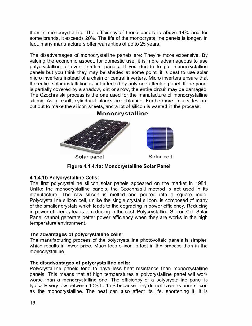
4.1.4.1b Polycrystalline Cells: The first polycrystalline silicon solar panels appeared on the market in 1981. Unlike the monocrystalline panels, the Czochralski method is not used in its manufacture. The raw silicon is melted and poured into a square mold. Polycrystalline silicon cell, unlike the single crystal silicon, is composed of many of the smaller crystals which leads to the degrading in power efficiency. Reducing in power efficiency leads to reducing in the cost. Polycrystalline Silicon Cell Solar Panel cannot generate better power efficiency when they are works in the high temperature environment. The advantages of polycrystalline cells: The manufacturing process of the polycrystalline photovoltaic panels is simpler, which results in lower price. Much less silicon is lost in the process than in the monocrystalline. The disadvantages of polycrystalline cells: Polycrystalline panels tend to have less heat resistance than monocrystalline panels. This means that at high temperatures a polycrystalline panel will work worse than a monocrystalline one. The efficiency of a polycrystalline panel is typically very low between 10% to 15% because they do not have as pure silicon as the monocrystalline. The heat can also affect its life, shortening it. It is
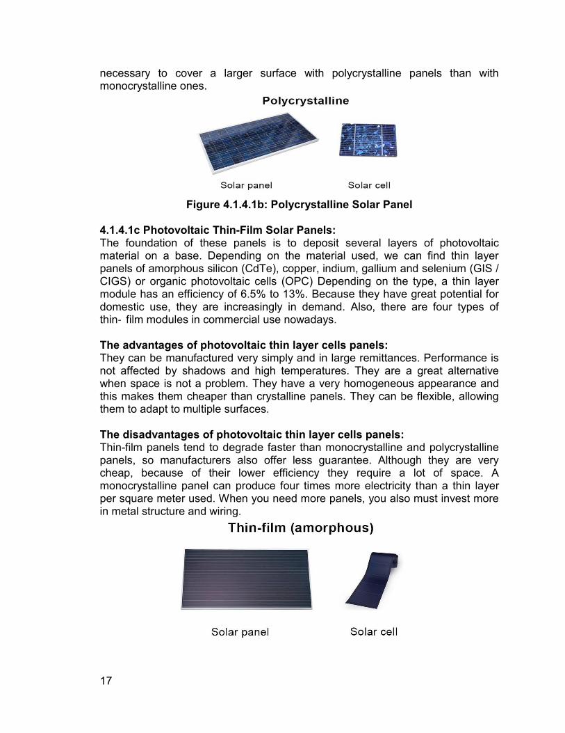
17
necessary to cover a larger surface with polycrystalline panels than with monocrystalline ones.
Figure 4.1.4.1b: Polycrystalline Solar Panel
4.1.4.1c Photovoltaic Thin-Film Solar Panels: The foundation of these panels is to deposit several layers of photovoltaic material on a base. Depending on the material used, we can find thin layer panels of amorphous silicon (CdTe), copper, indium, gallium and selenium (GIS / CIGS) or organic photovoltaic cells (OPC) Depending on the type, a thin layer module has an efficiency of 6.5% to 13%. Because they have great potential for domestic use, they are increasingly in demand. Also, there are four types of thin‐ film modules in commercial use nowadays. The advantages of photovoltaic thin layer cells panels: They can be manufactured very simply and in large remittances. Performance is not affected by shadows and high temperatures. They are a great alternative when space is not a problem. They have a very homogeneous appearance and this makes them cheaper than crystalline panels. They can be flexible, allowing them to adapt to multiple surfaces. The disadvantages of photovoltaic thin layer cells panels: Thin-film panels tend to degrade faster than monocrystalline and polycrystalline panels, so manufacturers also offer less guarantee. Although they are very cheap, because of their lower efficiency they require a lot of space. A monocrystalline panel can produce four times more electricity than a thin layer per square meter used. When you need more panels, you also must invest more in metal structure and wiring.
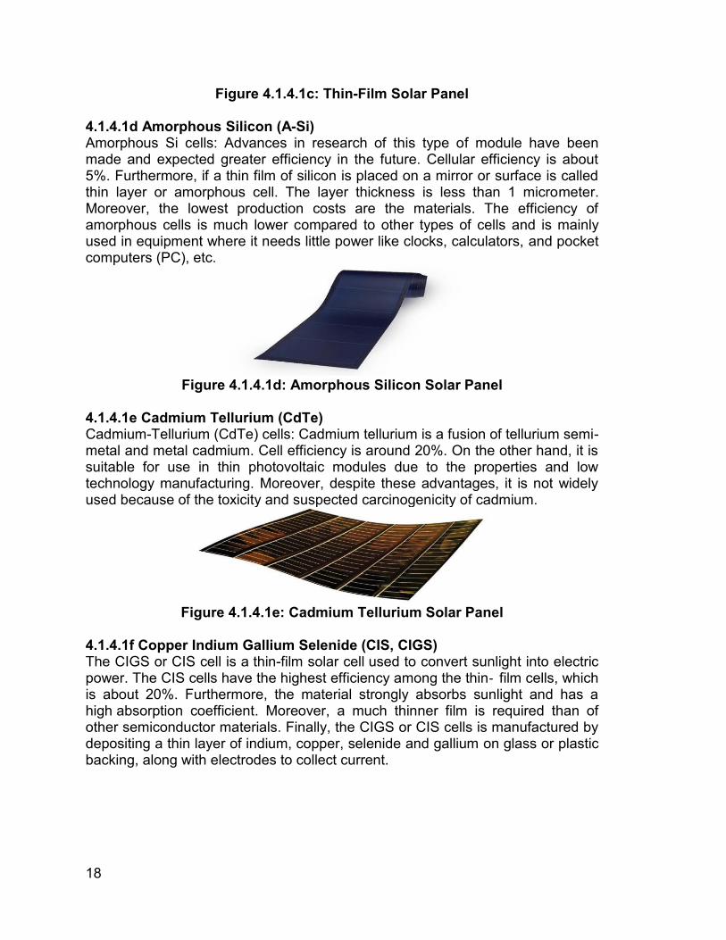
18
Figure 4.1.4.1c: Thin-Film Solar Panel 4.1.4.1d Amorphous Silicon (A-Si) Amorphous Si cells: Advances in research of this type of module have been made and expected greater efficiency in the future. Cellular efficiency is about 5%. Furthermore, if a thin film of silicon is placed on a mirror or surface is called thin layer or amorphous cell. The layer thickness is less than 1 micrometer. Moreover, the lowest production costs are the materials. The efficiency of amorphous cells is much lower compared to other types of cells and is mainly used in equipment where it needs little power like clocks, calculators, and pocket computers (PC), etc.
Figure 4.1.4.1d: Amorphous Silicon Solar Panel
4.1.4.1e Cadmium Tellurium (CdTe) Cadmium-Tellurium (CdTe) cells: Cadmium tellurium is a fusion of tellurium semi-metal and metal cadmium. Cell efficiency is around 20%. On the other hand, it is suitable for use in thin photovoltaic modules due to the properties and low technology manufacturing. Moreover, despite these advantages, it is not widely used because of the toxicity and suspected carcinogenicity of cadmium.
Figure 4.1.4.1e: Cadmium Tellurium Solar Panel
4.1.4.1f Copper Indium Gallium Selenide (CIS, CIGS) The CIGS or CIS cell is a thin-film solar cell used to convert sunlight into electric power. The CIS cells have the highest efficiency among the thin‐ film cells, which is about 20%. Furthermore, the material strongly absorbs sunlight and has a high absorption coefficient. Moreover, a much thinner film is required than of other semiconductor materials. Finally, the CIGS or CIS cells is manufactured by depositing a thin layer of indium, copper, selenide and gallium on glass or plastic backing, along with electrodes to collect current.
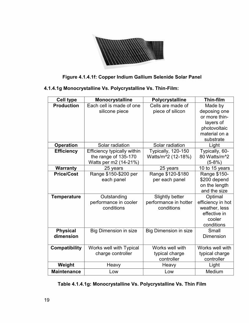
19
Figure 4.1.4.1f: Copper Indium Gallium Selenide Solar Panel
4.1.4.1g Monocrystalline Vs. Polycrystalline Vs. Thin-Film:
Cell type Monocrystalline Polycrystalline Thin-film Production Each cell is made of one
silicone piece Cells are made of
piece of silicon Made by
deposing one or more thin-
layers of photovoltaic material on a
substrate Operation Solar radiation Solar radiation Light Efficiency Efficiency typically within
the range of 135-170 Watts per m2 (14-21%)
Typically, 120-150 Watts/m^2 (12-18%)
Typically, 60-80 Watts/m^2
(5-8%) Warranty 25 years 25 years 10 to 15 years
Price/Cost Range $150-$200 per each panel
Range $120-$180 per each panel
Range $150-$200 depend on the length and the size
Temperature Outstanding performance in cooler
conditions
Slightly better performance in hotter
conditions
Optimal efficiency in hot weather, less effective in
cooler conditions
Physical dimension
Big Dimension in size Big Dimension in size Small Dimension
Compatibility Works well with Typical
charge controller Works well with typical charge
controller
Works well with typical charge
controller Weight Heavy Heavy Light
Maintenance Low Low Medium
Table 4.1.4.1g: Monocrystalline Vs. Polycrystalline Vs. Thin Film
20
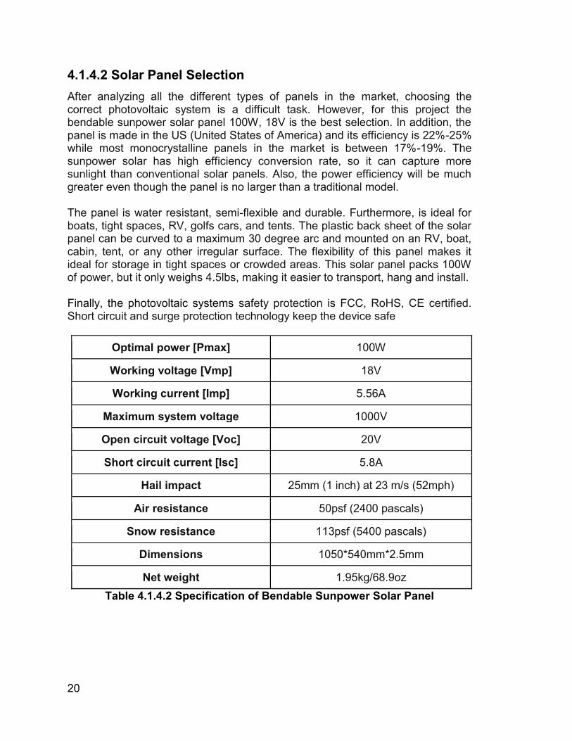
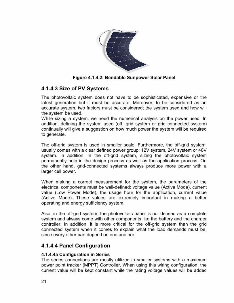
4.1.4.2 Solar Panel Selection After analyzing all the different types of panels in the market, choosing the correct photovoltaic system is a difficult task. However, for this project the bendable sunpower solar panel 100W, 18V is the best selection. In addition, the panel is made in the US (United States of America) and its efficiency is 22%-25% while most monocrystalline panels in the market is between 17%-19%. The sunpower solar has high efficiency conversion rate, so it can capture more sunlight than conventional solar panels. Also, the power efficiency will be much greater even though the panel is no larger than a traditional model. The panel is water resistant, semi-flexible and durable. Furthermore, is ideal for boats, tight spaces, RV, golfs cars, and tents. The plastic back sheet of the solar panel can be curved to a maximum 30 degree arc and mounted on an RV, boat, cabin, tent, or any other irregular surface. The flexibility of this panel makes it ideal for storage in tight spaces or crowded areas. This solar panel packs 100W of power, but it only weighs 4.5lbs, making it easier to transport, hang and install. Finally, the photovoltaic systems safety protection is FCC, RoHS, CE certified. Short circuit and surge protection technology keep the device safe
Optimal power [Pmax] 100W
Working voltage [Vmp] 18V
Working current [Imp] 5.56A
Maximum system voltage 1000V
Open circuit voltage [Voc] 20V
Short circuit current [Isc] 5.8A
Hail impact 25mm (1 inch) at 23 m/s (52mph)
Air resistance 50psf (2400 pascals)
Snow resistance 113psf (5400 pascals)
Dimensions 1050*540mm*2.5mm
Net weight 1.95kg/68.9oz Table 4.1.4.2 Specification of Bendable Sunpower Solar Panel
21
Figure 4.1.4.2: Bendable Sunpower Solar Panel
4.1.4.3 Size of PV Systems The photovoltaic system does not have to be sophisticated, expensive or the latest generation but it must be accurate. Moreover, to be considered as an accurate system, two factors must be considered; the system used and how will the system be used. While sizing a system, we need the numerical analysis on the power used. In addition, defining the system used (off- grid system or grid connected system) continually will give a suggestion on how much power the system will be required to generate. The off-grid system is used in smaller scale. Furthermore, the off-grid system, usually comes with a clear defined power group: 12V system, 24V system or 48V system. In addition, in the off-grid system, sizing the photovoltaic system permanently help in the design process as well as the application process. On the other hand, grid-connected systems always produce more power with a larger cell power. When making a correct measurement for the system, the parameters of the electrical components must be well-defined: voltage value (Active Mode), current value (Low Power Mode), the usage hour for the application, current value (Active Mode). These values are extremely important in making a better operating and energy sufficiency system. Also, in the off-grid system, the photovoltaic panel is not defined as a complete system and always come with other components like the battery and the charger controller. In addition, it is more critical for the off-grid system than the grid connected system when it comes to explain what the load demands must be, since every other part depend on one another. 4.1.4.4 Panel Configuration 4.1.4.4a Configuration in Series The series connections are mostly utilized in smaller systems with a maximum power point tracker (MPPT) Controller. When using this wiring configuration, the current value will be kept constant while the rating voltage values will be added
22
up. Connecting your panels in series will increase the voltage level and keep the same amperage. Furthermore, most of the diodes and transistors can be activated only by when the voltage reach to a certain level. The reason why series connections are utilized with maximum power point tracker controllers is that can accept a higher input voltage. Moreover, the benefits of using voltage as the input source for operating the system is that a certain level of voltage can be used the voltage regulators. The current input is constant and offers lower cost when it comes to choosing conducting wires. On the other hand, dissimilar the parallel configuration, the series configuration is more efficient when it comes to long distance wiring and helps to prevent the system power losses over long distance connection to the charge controller. Finally, the downside to series systems is shading problems, if one panel is shaded it will affect the whole string. This will not happen with the parallel connection, when panels are wired in series all in a sense depend on each other. 4.1.4.4b Configuration in Parallel The parallel configuration is the most common type of configuration. With this configuration, the system will remain the same rating voltage of each panel, and will increase in the rating current value. The parallel connections are mostly used in smaller systems, and with Pulse Width Modulation (PWM) Controllers, however they are exceptions. In today's market a panel with 12V is always cheaper than a panel with 12V and higher rating in current. On the other hand, connecting the panels in parallel will increase the amps and keep the same voltage, this is often used in 12V systems with multiple panels. However, the 12V panels in parallel allows charging capabilities of 12V. In addition, if we connect another identical panel, the system will end up having the rating voltage 12V and the rating current adding up by twice. The downside of parallel systems is that high amperage is laborious to travel long distances without using thick wires. Also, paralleling systems require extra equipment like branch connectors. Having the system in the parallel configuration, the current always will be the main force for the application. One of the main benefits of having the current to be the main controlling is that electrical applications are driven by current. In addition, we need variety of current input for different applications: the controller, the DC-AC converter and the lighting system. Therefore, there is DC-AC converting as one of our applications, having the current as the driven input can help to optimize the system for efficiency purpose. However, the applications require different input rating current. Some benefit of having the current to be the controlling variable would be safety. It is easier for protecting the system by keeping the current regulated than the voltage. Also, there are few disadvantages: having current too large will require larger and more expensive conducting wires, if the distance from the solar panel to the charge controller are too long, the voltage input have
23
high potential to be dropped and the variation between the input and the output can cause the system inefficient which we all want to prevent. 4.1.4.4c Combination in series and parallel This configuration offers better solution for a large scale application that utilize the most energy from solar panels. This configuration is the combination between the parallel and series configuration in which the voltage and the current rating value can be added up depending on the specification of the demands. Solar Panel Combination of series and parallel arrays are usually limited by one factor the charge controller. The charge controllers are designed to accept an amount of amperage and voltage. Moreover, to stay within the parameters of amperage and voltage, we have utilized a series parallel connection. On the other hand, for this connection, a string is created by two or more panels in series. Next, an equal string needs to be created in parallel. Furthermore, four panels in series needs to be parallel with another four panels in series or there will be some serious power loss. Having the system to be constructed in this configuration, the system will be more efficient in power, and more cost effective. However, to have this configuration setting up for the system, there requires at least four panels for the system. Finally, there is not a downside to series parallel connections and they are usually used when needed. 4.1.4.5 Environmental Impact of PV Systems The environmental impact associated with PV systems are the following, the toxic and harmful materials used in the production of PV cells, the energy required to produce the photovoltaic systems, and what happens to the PV systems at the end of their lifetime period. Also, some of the common harmful chemicals involved in crystalline photovoltaic manufacture are: Sulphur Hexafluoride used to clean the reactor used in silicon production and if the product escaped it would be a very powerful greenhouse gas. Also, it can react with silicon to create a variety of other compounds. The main component of photovoltaic cells is silicon. Silicon is not a harmful material, but parts of the manufacturing process involve toxic chemicals and they need to be carefully controlled and regulated to prevent environmental damage. Crystalline silicon is made via silane gas. Moreover, the production results in waste silicon tetrachloride which is toxic. Silane gas has the potential to cause harm, also lead, aluminum and silver in the electronics. The use of lead based solder would lead to pollution problems. With the exclusion of amorphous silicon, most commercially established photovoltaics technologies use toxic heavy metals. CIGS often uses a CdS buffer layer, and the semiconductor material of CdTe-technology itself contains the toxic cadmium (Cd).). Moreover, the paste used for screen printing front and back contacts contains traces of Pb and sometimes Cd as well.
24
Furthermore, making monocrystalline panels tends to result in a lot of waste, as they are made from slices of silicon ingots leaving offcuts. However, this waste can be used to make polycrystalline or multi-crystalline photovoltaic systems. In addition, the thin film silicon decreases the volume of the material by spraying a thin layer of silicon onto a surface, this has a potential impact and reduce waste. The recycling of photovoltaic equipment does need to be developed at the end of its life. The PV systems are being phased into waste electrical and electronic equipment. Finally, the manufacturer is responsible for the final disposal recycling.
25
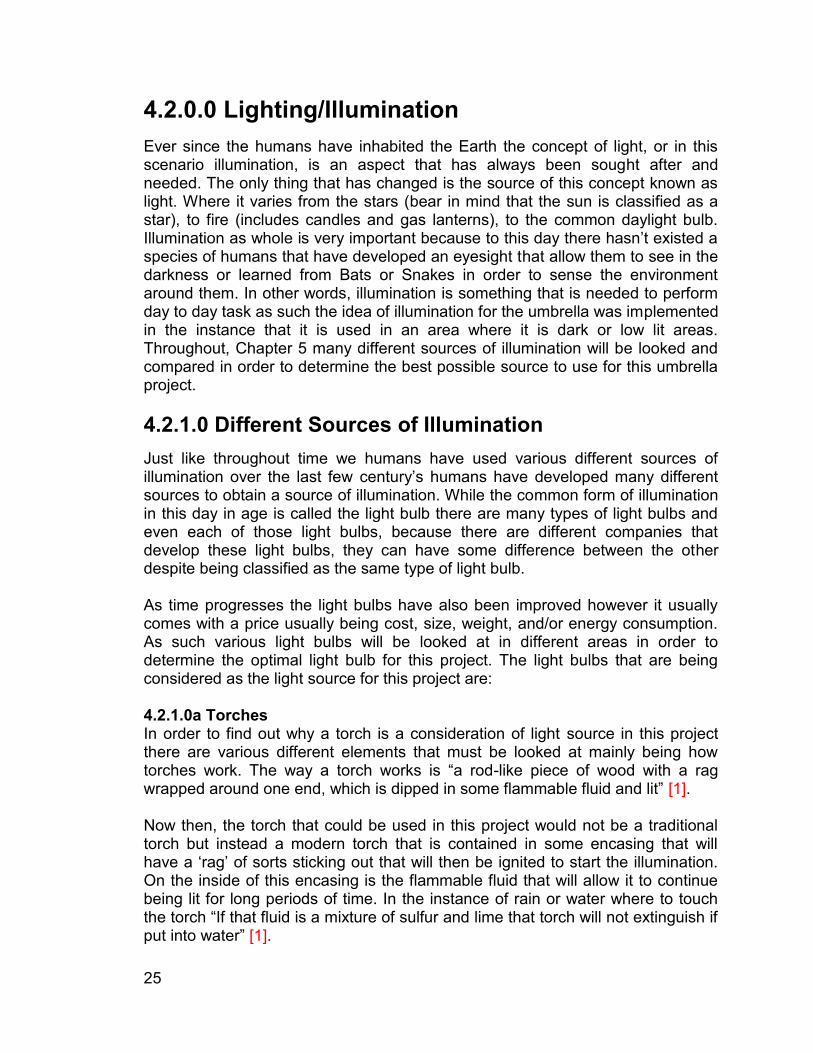
4.2.0.0 Lighting/Illumination Ever since the humans have inhabited the Earth the concept of light, or in this scenario illumination, is an aspect that has always been sought after and needed. The only thing that has changed is the source of this concept known as light. Where it varies from the stars (bear in mind that the sun is classified as a star), to fire (includes candles and gas lanterns), to the common daylight bulb. Illumination as whole is very important because to this day there hasn’t existed a species of humans that have developed an eyesight that allow them to see in the darkness or learned from Bats or Snakes in order to sense the environment around them. In other words, illumination is something that is needed to perform day to day task as such the idea of illumination for the umbrella was implemented in the instance that it is used in an area where it is dark or low lit areas. Throughout, Chapter 5 many different sources of illumination will be looked and compared in order to determine the best possible source to use for this umbrella project. 4.2.1.0 Different Sources of Illumination Just like throughout time we humans have used various different sources of illumination over the last few century’s humans have developed many different sources to obtain a source of illumination. While the common form of illumination in this day in age is called the light bulb there are many types of light bulbs and even each of those light bulbs, because there are different companies that develop these light bulbs, they can have some difference between the other despite being classified as the same type of light bulb. As time progresses the light bulbs have also been improved however it usually comes with a price usually being cost, size, weight, and/or energy consumption. As such various light bulbs will be looked at in different areas in order to determine the optimal light bulb for this project. The light bulbs that are being considered as the light source for this project are: 4.2.1.0a Torches In order to find out why a torch is a consideration of light source in this project there are various different elements that must be looked at mainly being how torches work. The way a torch works is “a rod-like piece of wood with a rag wrapped around one end, which is dipped in some flammable fluid and lit” [1]. Now then, the torch that could be used in this project would not be a traditional torch but instead a modern torch that is contained in some encasing that will have a ‘rag’ of sorts sticking out that will then be ignited to start the illumination. On the inside of this encasing is the flammable fluid that will allow it to continue being lit for long periods of time. In the instance of rain or water where to touch the torch “If that fluid is a mixture of sulfur and lime that torch will not extinguish if put into water” [1].
26
Figure 4.2.1.0a: Torch
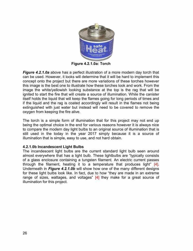
Figure 4.2.1.0a above has a perfect illustration of a more modern day torch that can be used. However, it looks will determine that it will be hard to implement this concept onto the project but there are more variations of these torches however this image is the best one to illustrate how these torches look and work. From the image the white/yellowish looking substance at the top is the rag that will be ignited to start the fire that will create a source of illumination. While the canister itself holds the liquid that will keep the flames going for long periods of times and if the liquid and the rag is coated accordingly will result in the flames not being extinguished with just water but instead will need to be covered to remove the oxygen from keeping the fire alive. The torch is a simple form of illumination that for this project may not end up being the optimal choice in the end for various reasons however it is always nice to compare the modern day light bulbs to an original source of illumination that is still used in the today in the year 2017 simply because it is a source of illumination that is simple, easy to use, and not hard obtain. 4.2.1.0b Incandescent Light Bulbs The incandescent light bulbs are the current standard light bulb seen around almost everywhere that has a light bulb. These lightbulbs are “typically consists of a glass enclosure containing a tungsten filament. An electric current passes through the filament, heating it to a temperature that produces light” [4]. Underneath in Figure 4.2.1.0b will show how one of the many different designs for these light bulbs look like. In fact, due to how “they are made in an extreme range of sizes, wattages, and voltages” [4] they make for a great source of illumination for this project.
27
Figure 4.2.1.0b: Incandescent Light Bulb
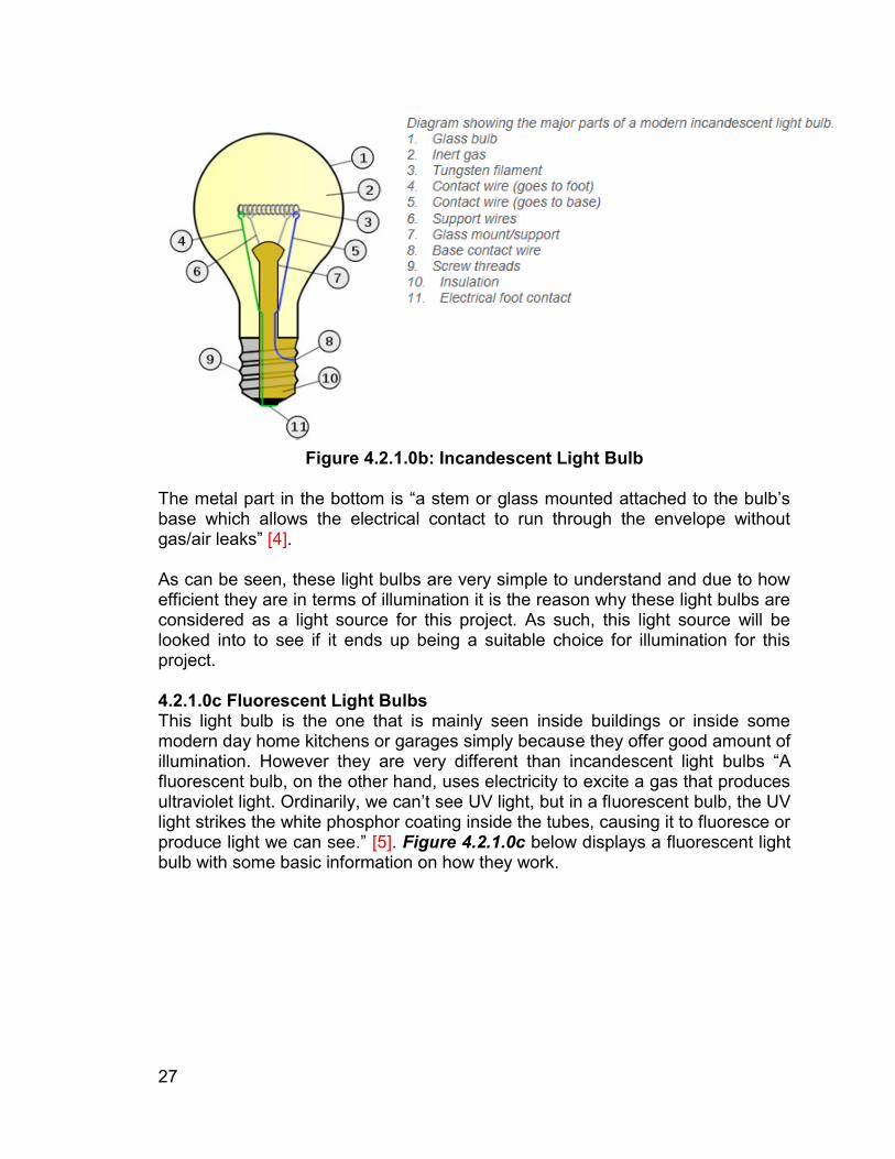
The metal part in the bottom is “a stem or glass mounted attached to the bulb’s base which allows the electrical contact to run through the envelope without gas/air leaks” [4]. As can be seen, these light bulbs are very simple to understand and due to how efficient they are in terms of illumination it is the reason why these light bulbs are considered as a light source for this project. As such, this light source will be looked into to see if it ends up being a suitable choice for illumination for this project. 4.2.1.0c Fluorescent Light Bulbs This light bulb is the one that is mainly seen inside buildings or inside some modern day home kitchens or garages simply because they offer good amount of illumination. However they are very different than incandescent light bulbs “A fluorescent bulb, on the other hand, uses electricity to excite a gas that produces ultraviolet light. Ordinarily, we can’t see UV light, but in a fluorescent bulb, the UV light strikes the white phosphor coating inside the tubes, causing it to fluoresce or produce light we can see.” [5]. Figure 4.2.1.0c below displays a fluorescent light bulb with some basic information on how they work.
28
Figure 4.2.1.0c: Fluorescent Light Bulb
Fluorescent light bulbs work by when electricity runs through the pins it starts to ignite the electrodes, which are very similar to the filament for incandescent light bulbs. These electrodes then ‘excites the electrons from both the argon gas and metal inside creating a sort of illumination what is encased in some form of tubing that allows the user to use as illumination.
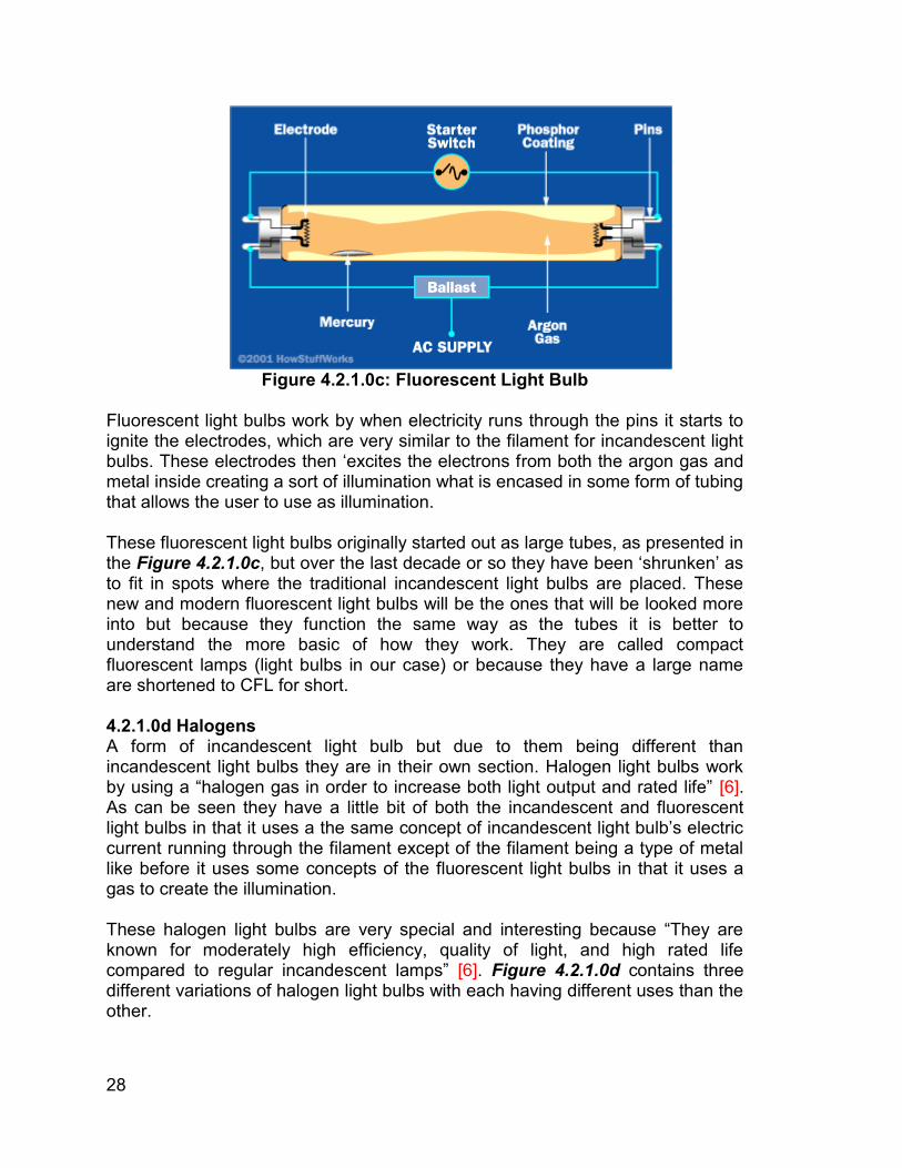
These fluorescent light bulbs originally started out as large tubes, as presented in the Figure 4.2.1.0c, but over the last decade or so they have been ‘shrunken’ as to fit in spots where the traditional incandescent light bulbs are placed. These new and modern fluorescent light bulbs will be the ones that will be looked more into but because they function the same way as the tubes it is better to understand the more basic of how they work. They are called compact fluorescent lamps (light bulbs in our case) or because they have a large name are shortened to CFL for short. 4.2.1.0d Halogens A form of incandescent light bulb but due to them being different than incandescent light bulbs they are in their own section. Halogen light bulbs work by using a “halogen gas in order to increase both light output and rated life” [6]. As can be seen they have a little bit of both the incandescent and fluorescent light bulbs in that it uses a the same concept of incandescent light bulb’s electric current running through the filament except of the filament being a type of metal like before it uses some concepts of the fluorescent light bulbs in that it uses a gas to create the illumination. These halogen light bulbs are very special and interesting because “They are known for moderately high efficiency, quality of light, and high rated life compared to regular incandescent lamps” [6]. Figure 4.2.1.0d contains three different variations of halogen light bulbs with each having different uses than the other.
29
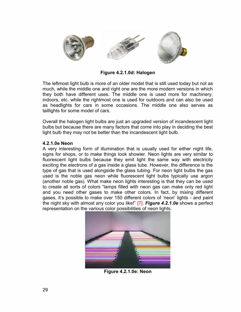
Figure 4.2.1.0d: Halogen
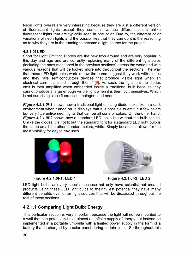
The leftmost light bulb is more of an older model that is still used today but not as much, while the middle one and right one are the more modern versions in which they both have different uses. The middle one is used more for machinery, indoors, etc. while the rightmost one is used for outdoors and can also be used as headlights for cars in some occasions. The middle one also serves as taillights for some model of cars. Overall the halogen light bulbs are just an upgraded version of incandescent light bulbs but because there are many factors that come into play in deciding the best light bulb they may not be better than the incandescent light bulb. 4.2.1.0e Neon A very interesting form of illumination that is usually used for either night life, signs for shops, or to make things look showier. Neon lights are very similar to fluorescent light bulbs because they emit light the same way with electricity exciting the electrons of a gas inside a glass tube. However, the difference is the type of gas that is used alongside the glass tubing. For neon light bulbs the gas used is the noble gas neon while fluorescent light bulbs typically use argon (another noble gas). What make neon lights interesting is that they can be used to create all sorts of colors “lamps filled with neon gas can make only red light and you need other gases to make other colors. In fact, by mixing different gases, it’s possible to make over 150 different colors of ‘neon’ lights - and paint the night sky with almost any color you like!” [7]. Figure 4.2.1.0e shows a perfect representation on the various color possibilities of neon lights.
Figure 4.2.1.0e: Neon
30
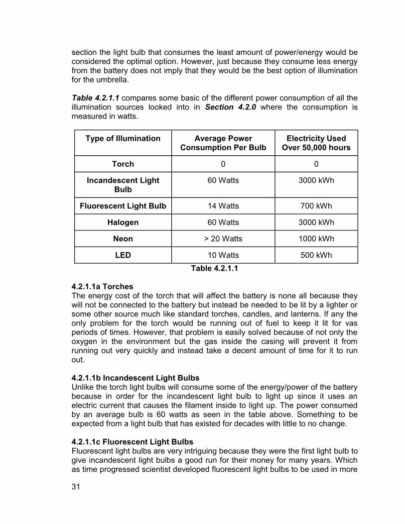
Neon lights overall are very interesting because they are just a different version of fluorescent lights except they come in various different colors unlike fluorescent lights that are typically seen in one color. Due to, the different color variations of neon lights and the possibilities that they can do it is the reasoning as to why they are in the running to become a light source for the project. 4.2.1.0f LED Short for Light Emitting Diodes are the new toys around and are very popular in this day and age and are currently replacing many of the different light bulbs (including the ones mentioned in the previous sections) across the world and with various reasons that will be looked more into throughout the sections. The way that these LED light bulbs work is how the name suggest they work with diodes and they “are semiconductors devices that produce visible light when an electrical current passed through them.” [9]. As such, the light that the diodes emit is then amplified when embedded inside a traditional bulb because they cannot produce a large enough visible light when it is them by themselves. Which is not surprising since fluorescent, halogen, and neon Figure 4.2.1.0f-1 shows how a traditional light emitting diode looks like in a dark environment when turned on. It displays that it is possible to emit in a few colors but very little unlike neon lights that can be all sorts of colors. On the other hand, Figure 4.2.1.0f-2 shows how a standard LED looks like without the bulb casing. Unlike the diodes it is not lit but the standard light for a standard LED light bulb is the same as all the other standard colors, white. Simply because it allows for the most visibility for day to day uses.
Figure 4.2.1.0f-1: LED 1 Figure 4.2.1.0f-2: LED 2
LED light bulbs are very special because not only have scientist not created products using these LED light bulbs to their fullest potential they have many different benefits over other light sources that will be discussed throughout the rest of these sections. 4.2.1.1 Comparing Light Bulb: Energy This particular section is very important because the light will not be mounted to a wall that can potentially have almost an infinite supply of energy but instead be implemented in a portable umbrella with a limited power supply in the form of a battery that is charged by a solar panel during certain times. So throughout this
31
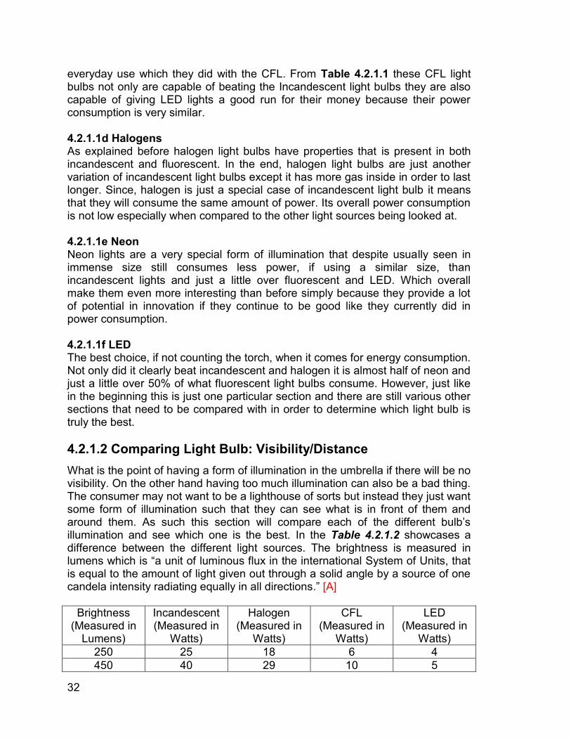
section the light bulb that consumes the least amount of power/energy would be considered the optimal option. However, just because they consume less energy from the battery does not imply that they would be the best option of illumination for the umbrella. Table 4.2.1.1 compares some basic of the different power consumption of all the illumination sources looked into in Section 4.2.0 where the consumption is measured in watts.
Type of Illumination Average Power Consumption Per Bulb
Electricity Used Over 50,000 hours
Torch 0 0
Incandescent Light Bulb
60 Watts 3000 kWh
Fluorescent Light Bulb 14 Watts 700 kWh
Halogen 60 Watts 3000 kWh
Neon > 20 Watts 1000 kWh
LED 10 Watts 500 kWh Table 4.2.1.1
4.2.1.1a Torches The energy cost of the torch that will affect the battery is none all because they will not be connected to the battery but instead be needed to be lit by a lighter or some other source much like standard torches, candles, and lanterns. If any the only problem for the torch would be running out of fuel to keep it lit for vas periods of times. However, that problem is easily solved because of not only the oxygen in the environment but the gas inside the casing will prevent it from running out very quickly and instead take a decent amount of time for it to run out. 4.2.1.1b Incandescent Light Bulbs Unlike the torch light bulbs will consume some of the energy/power of the battery because in order for the incandescent light bulb to light up since it uses an electric current that causes the filament inside to light up. The power consumed by an average bulb is 60 watts as seen in the table above. Something to be expected from a light bulb that has existed for decades with little to no change. 4.2.1.1c Fluorescent Light Bulbs Fluorescent light bulbs are very intriguing because they were the first light bulb to give incandescent light bulbs a good run for their money for many years. Which as time progressed scientist developed fluorescent light bulbs to be used in more
32
everyday use which they did with the CFL. From Table 4.2.1.1 these CFL light bulbs not only are capable of beating the Incandescent light bulbs they are also capable of giving LED lights a good run for their money because their power consumption is very similar. 4.2.1.1d Halogens As explained before halogen light bulbs have properties that is present in both incandescent and fluorescent. In the end, halogen light bulbs are just another variation of incandescent light bulbs except it has more gas inside in order to last longer. Since, halogen is just a special case of incandescent light bulb it means that they will consume the same amount of power. Its overall power consumption is not low especially when compared to the other light sources being looked at. 4.2.1.1e Neon Neon lights are a very special form of illumination that despite usually seen in immense size still consumes less power, if using a similar size, than incandescent lights and just a little over fluorescent and LED. Which overall make them even more interesting than before simply because they provide a lot of potential in innovation if they continue to be good like they currently did in power consumption. 4.2.1.1f LED The best choice, if not counting the torch, when it comes for energy consumption. Not only did it clearly beat incandescent and halogen it is almost half of neon and just a little over 50% of what fluorescent light bulbs consume. However, just like in the beginning this is just one particular section and there are still various other sections that need to be compared with in order to determine which light bulb is truly the best. 4.2.1.2 Comparing Light Bulb: Visibility/Distance What is the point of having a form of illumination in the umbrella if there will be no visibility. On the other hand having too much illumination can also be a bad thing. The consumer may not want to be a lighthouse of sorts but instead they just want some form of illumination such that they can see what is in front of them and around them. As such this section will compare each of the different bulb’s illumination and see which one is the best. In the Table 4.2.1.2 showcases a difference between the different light sources. The brightness is measured in lumens which is “a unit of luminous flux in the international System of Units, that is equal to the amount of light given out through a solid angle by a source of one candela intensity radiating equally in all directions.” [A]
Brightness (Measured in
Lumens)
Incandescent (Measured in
Watts)
Halogen (Measured in
Watts)
CFL (Measured in
Watts)
LED (Measured in
Watts) 250 25 18 6 4 450 40 29 10 5

33
800 60 43 13 10 1100 75 53 18 15 1600 100 72 23 20
Table 4.2.1.2: Visibility of Light Bulbs 4.2.1.2a Torches Due to torches being similar to a candle this aspect of it can also be applied “Considering the absolute threshold, the brightness of a candle flame, and the way a glowing object dimes according to the square of the distance away from it, visions scientists conclude that one could make out the faint glimmer of a candle up to 30 miles away” [8]. In the end, yes torches are decent light source but will not allow a decent lighting to the area that the umbrella is going to be used in. 4.2.1.2b Incandescent Light Bulbs As can be seen in the table above the illumination for Incandescent light bulbs is decent the problem with them is that they require a lot more power in order to produce the same illumination compared to all the other light sources looked at. 4.2.1.2c Fluorescent Light Bulbs From Table 4.2.1.2 CFLs were the second best in terms of illumination vs. power consumption. This is very good for CFL because overall they are a really good light bulb. It also shows how much of an improvement CFLs are compared to Incandescent light bulbs. 4.2.1.2d Halogens The illumination for Halogens is still a lot better than Incandescent light bulbs however they fall short compared to CFLs and LEDs. They are still an overall good source of illumination when using the umbrella for basic tasks but when trying to use it in places that require more illumination it may cause some problems due to its power consumption compared to the other light sources. 4.2.1.2e Neon Neon as explained are just a combination of both Fluorescent and Halogen light bulbs. As such their illumination is very similar. The reason as to why they were not expanded upon like the other light sources is because they are more of a situational source of illumination unlike the others that could be used no matter what the situation. 4.2.1.2f LED When looking at Table 4.2.1.2 the best light source is LEDs which is correct because not only are they capable of emitting 1600 lumens with 20W they are able to produce 800 lumens with just 10W which is the standard level of illumination for day to day uses. In other words, varying what this umbrella will be doing either a 10W, 15W, or 20W is more than enough however for this project a 4W or 5W is also good amount due to the purpose of this project is to just show that the lights work and they can be seen.
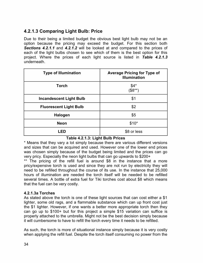
34
4.2.1.3 Comparing Light Bulb: Price Due to their being a limited budget the obvious best light bulb may not be an option because the pricing may exceed the budget. For this section both Sections 4.2.1.1 and 4.2.1.2 will be looked at and compared to the prices of each of the light bulbs chosen to see which of them is the best option for this project. Where the prices of each light source is listed in Table 4.2.1.3 underneath.
Type of Illumination Average Pricing for Type of Illumination
Torch $4* ($8**)
Incandescent Light Bulb $1
Fluorescent Light Bulb $2
Halogen $5
Neon $10*
LED $8 or less Table 4.2.1.3: Light Bulb Prices
* Means that they vary a lot simply because there are various different versions and sizes that can be acquired and used. However one of the lower end prices was chosen simply because of the budget being limited and the prices can go very pricy. Especially the neon light bulbs that can go upwards to $200+ ** The pricing of the refill fuel is around $8 in the instance that a more pricy/expensive torch is used and since they are not run by electricity they will need to be refilled throughout the course of its use. In the instance that 25,000 hours of illumination are needed the torch itself will be needed to be refilled several times. A bottle of extra fuel for Tiki torches cost about $8 which means that the fuel can be very costly. 4.2.1.3a Torches As stated above the torch is one of these light sources that can cost either a $1 lighter, some old rags, and a flammable substance which can up front cost just the $1 lighter. However, if one wants a better more appropriate torch then they can go up to $100+ but for this project a simple $15 variation can suffice is properly attached to the umbrella. Might not be the best decision simply because it will cumbersome to have to refill the torch every time it needs to be refilled. As such, the torch is more of situational instance simply because it is very costly when applying the refill fuel. Despite the torch itself consuming no power from the
35
battery in this particular area it is very costly to the project because not only will the torch need to be designed in a specific way to fit the umbrella it is going to have to do so while providing a decent source of illumination. 4.2.1.3b Incandescent Light Bulbs The largest advantage that Incandescent light bulbs have over all the others is that they are very cheap. This cost usually being $1 for just one bulb which is very cheap when compared to others such as LEDs which cost $8. The only problem is that because of how incandescent light bulbs work they require to be replaced more often than LEDs, CFLs, and even Halogen. As to the frequency of which these light bulbs need to be swapped varies not only by the brand but the type of light bulb. So yes incandescent light bulbs only cost $1 but in the long run may require to be changed more often than all the other light sources which will make the final cost be higher in a few years. 4.2.1.3c Fluorescent Light Bulbs Very good source of illumination as seen in the previous sections and this section is no exception. With an amazing average cost of $2 (just a $1 more than the cheapest light bulb, incandescent) and all the other amazing features that were discussed in the previous sections. Overall not only is the price for this light source very good they are also capable of being one of the best. 4.2.1.3d Halogens Halogens are 2.5x the price of Fluorescent lights and produce less illumination than both Fluorescent and LED for the same power as displayed in Table 4.2.1.2. Overall, Halogens have not been doing much to be impressive as the choice but they are still a decent source of illumination compared to many of the other options. 4.2.1.3e Neon Throughout all of these comparisons they have been at a more awkward position than Halogens but have been looked at not because they are the best but because there is a niche use for these type of lights. As explained at first these lights are more for a ‘party’ environment unlike all the others and it is because of this reason that they are being considered. 4.2.1.3f LED When LEDs first came out they were not even considered because of how expensive it was to create them since they are semiconductor devices. Another reason as to why LEDs were very expensive many years ago is because their wasn’t an effective way to make them smaller but as the years went by not only was the technology available to create the semiconductor devices that operate them, diodes, become easier to create in abundance the pricing of the diodes themselves decreased which allowed companies to potentially consider of using more diodes in their products which then later led them to create LED lights. At first, LED lights use to cost above $40 for just one bulb but now a day they can
36
be bought for about $8 as shown in the table above and as time progresses and technology gets much better the there is a high chance that the prices for LED lights will go down unlike the other light sources whose prices will likely stay around the same due to them reaching their peak unlike LED who can only get better as each day passes. 4.2.1.4 Comparing Light Bulb: Psychological It has been scientifically proven that different colors and shading affect how people react and do their day to day things. As such, light bulbs are also a part of this psychological affect. Not only does lighting affect a person psychologically but it also can determine the type of mood, improve the area by giving it that fancy vibe, or even allow the people to do their task at a different rate and it is for these reasons why a psychological aspect is being looked at. To show that for day to day uses one may be better than other but in different scenarios another one might be better. 4.2.1.4a Torches The torch, lantern, and candles have several benefits that the other light sources do not have in terms of psychological affect to people. The reason for this is because how in recent times ‘low light’ environments are viewed as calm, fancy, and in some instances professional. Something to note about the torch which can also be applied to the lanterns and candles is that “Torch was used as a symbol of hope, life (and, if turned upside down, of death and mourning), and enlightenment.” [1]. 4.2.1.4b Incandescent Light Bulbs These light sources are the very basic light source and as such are typically more associated with elderly people since they are the ones that have had more experience with these light sources unlike the youth now a day that are used to the modern light sources. This not mean that incandescent lights are bad or just associated with the elderly. It just means that in the year 2017 these types of lights not only are becoming an endangered species they typically require additional equipment to be utilized to their fullest unlike the other light sources. Another, problem as discussed in earlier sections is that they require more power and tend to be replaced more so in the end using incandescent lights as a source for a psychological impact to a person may not be the best option. 4.2.1.4c Fluorescent Light Bulbs Fluorescent lights are an interesting source of illumination because they are capable of doing various aspects. Since, they are the ones that came after incandescent light bulbs they have allowed for much improvements to do various tasks. The biggest one being that because they don’t require much power and they do not need to be changed as often as incandescent these two features allow fluorescent to be very good source of psychological impact. In other words,
37
not only would it make your mind calmer because the buyer saved some money it allows for more advantages that incandescent light bulbs were not able to do before. A large advantage that Fluorescent lights have is that the glass casing can be swapped for a colored case instead of just a glass case in order to create a different color of light which again creates yet another psychological effect to the people that see the colors. 4.2.1.4d Halogens Halogens extend more of what incandescent light bulbs do except they are a tad more costly and are effected by the same issues. Except the one that requires to be swapped a tad more often than incandescent. One advantage that Halogens have is that they are able to follow in the steps of fluorescent lighting and the material inside that creates the illumination can be swapped for another and instead of creating a basic white color they can produce another color that can later be amplified by changing the bulb/casing. 4.2.1.4e Neon As stated in Section 4.2.1.0 Neon lights tend to give a different feeling/vibe than the other lights because they are associated with night life or a party lifestyle. As such, they tend to make people feel more excited than normal or give a club or party a different type of environment simply because of the light source that is illumination the area. 4.2.1.4f LED LEDs are very similar to Fluorescent lights in that the encasing can be swapped for another color to produce various colors of LEDs. An advantage that LEDs have is that they already produce red, green, and blue colors naturally. However they are hard to obtain normally. Red and green colors are more natural while blue requires more work. A huge advantage that this feature has over the light sources is that they do not require a special casing to produce a colored light but instead require a special casing to produce the white light. So in the psychological aspect that is a plus. A huge advantage that LEDs have is that they can come in all sorts of colors which allow for various types of psychological aspects. However, for this project even though psychological aspects is something good to see in the end the standard white variation or even green is the best options due to them being either the standard or a color that provides good visibility to the users unlike various others colors. (Yellow is included in the white since there are times when there is no difference between the two unless it is a more intense yellow variation.)
38
4.2.1.5 Comparing Light Bulb: Weight & Design Due to the light bulb being integrated with the canopy of the umbrella in some way shape or form the weight of the light source cannot weigh to much while having the ability to bend or at least shape itself around the outer layer of the canopy or if another light source other than a light bulb is chosen then a factor of flexibility without causing any complications when being folded must be either implemented and considered. 4.2.1.5a Torches Much like all the other sections regarding the torch they vary depending on the version chosen. For this one a tiki torch cannot be chosen because then the pole will have to become the shaft for the umbrella, the fire at the top will not give that much illumination to the people underneath the umbrella, and the overall construction will have to be very delicate as to not cause any problems with all the other elements that incorporate this umbrella apparatus. However there are some smaller versions of tiki torches that can be used as a source with the only problem is that they will either be embedded In the shaft (which will also be a tad more problematic like the tiki but ) or have some small torches hanging from the ribs of the umbrella. In any case things can and will most likely get ugly when implementing this source of illumination because torches tend to be produced by flames that if various different scenarios are not accounted for can ignite not just the flammable substance of the torch but the entire umbrella. So for now torches are an overall interesting idea to be implemented to the umbrella they in the end are not a good source of illumination for the umbrella due to the many risks and complications associated with them. 4.2.1.5b Incandescent Light Bulbs Much like the torch these incandescent light bulbs have not gotten much love and this section is no exception. Due to the lights being implemented to the umbrella instead of just hanging down the light source needs to be flexible and have the functionality to be implemented in any are of the umbrella and not just the shaft/pole. This is where things get a tad complicated because instead of looking at the light bulbs shown in the figures in Section 4.2.1.0 they will have to be light strips. This is where complications happen with incandescent lights in that they are not best when it comes to light strips due to how large the light strips tend to be when compared to the others. Another, problem with these light strips is that the illumination from them is very little and even though this project just needs a little source of illumination having a decent source of illumination is optimal and as such an incandescent light strip will not be picked to be the source of illumination for this umbrella. 4.2.1.5c Fluorescent Light Bulbs The typical light source used inside buildings is Fluorescent light bulbs and the reason for that is because they tend to be large when being used in strips which is very good especially when all the other aspects of fluorescent lighting are considered. However, much like everything else there is a catch and for
39
Fluorescent lighting the catch is the size and weight. Yes they are convenient in that they already come in a light strip but the problem is that they are not flexible and if something were to happen to the glass not only is the light bulb useless the gas inside it can be released which if inhaled can cause problems to the human body. As such fluorescent light bulbs are not the best option due to how delicate they can be when being implemented to the umbrella. 4.2.1.5d Halogens Halogen lights are very similar to incandescent light bulbs and as such there are various problems associated with them despite their light strip being better than fluorescent lights they are still delicate when being folded and used. However, the biggest problem with them is that the illumination that they produce is not large enough for the power they will be consuming. 4.2.1.5e Neon Neon lights are very interesting because they come in arguably the best form of light strip when compared to the other light sources. The problem with Neon light strips is not the size, weight, or implementation but instead the cost, power, and usability. The cost for these Neon light strips is a tad more expensive than all the others especially if a good one is chosen. Another, thing is the overall power being consumed by these light strips is higher than all the others light sources and due to the project having a limited power supply this functionality can cause problems in draining the battery/power which is something that should not be done since the charging station should get more dedicated power than the source of illumination. 4.2.1.5f LED Last but certainly not least, is LEDs. Throughout the comparison portion LEDs have shown to be an excellent source of illumination and this area is no exception. LEDs have all the benefits that all the other lights sources had such as low power consumption, flexible light strips, emit a decent amount of illumination, and a low price. As per size and weight for this light strip it will be discussed in more depth in later sections in more details. 4.2.2.0 Light Bulb Chosen Now that various different light sources have been looked at and expanded upon in various areas only three different ones are really the best possible choice because of their energy efficiency and cost overall. These three sources where CFL, Halogen, and LED with the reasons as to why being the entire Section 4.2.1 above. However because not all three can be put in the project only one will be able to become the light source of the umbrella. As such underneath is a brief explanation as to why and why not this light source can be a possible addition to the umbrella.
40
4.2.2.0a Fluorescent Light Bulbs Positive things about the CFL is that they “Can last eight-to-10 time longer than incandescent bulbs. Can use 75 percent less energy than incandescent light bulbs.” [10]. This is the simple reason as to why the incandescent light bulb is not being considered. Simply because these three sources are able to not just last longer but in the end will cost less and the consumer will have to worry less about going around switching the light sources. Another good thing about them is that “Available in different sizes and shapes to fit almost any fixture” [10]. Overall that is perfect simply because this light source will not be connected to a traditional light socket but instead to either the actual power structure or even the charging station. One bad thing about them that can be overlooked in certain instances is that “Some operate off of a delayed start and can take up to three minutes to reach full light output” [10]. Again, not a bad thing but for some people it can be annoying having to wait about three minutes for the full light output to be achieved. To continue, with negative things about CFLs is that “CFLs were the first viable alternative to standard incandescent lamps, but many buyers continue to complain about warm up time, light quality and dimmability. Believing that LEDs can do more, and that fewer choices can benefit consumers best, GE (General Electric) will exit the CFL market in North America in 2017” [10]. From that statement it clearly shows that the general public is not the happiest regarding the CFL. But when compared to Incandescent light bulbs they are still the better option and is the reason why CFL are being considered to be one of the choices for this umbrella. Even if it is 2017 and GE wants to exit the CFL market in North America. 4.2.2.0b Halogens These type of light bulbs are very special because unlike the Fluorescent and LED light bulbs Halogen light bulbs are more for places to “Display lighting where users want to spotlight merchandise or outdoor applications where bright light is needed; office lamps.” [10]. This is one of the reasons as to why Halogen light bulbs are being considered as one of sources of illumination for the umbrella. They are great for displaying things in the outside which this umbrella will mainly be at. A good thing about this over the CFLs is that they do not have a slow start in lighting up but instead just start at the a specific level. However, the best thing about them is that they are “Fully dimmable” & “Produces a bright, crisp light” [10]. So in the instance where the light is not needed to be very bright it can be reduced to a more appropriate level as to not bother people.
41
Not everything can be peaches and creams and this is no exception. Halogen light bulbs have their own issues such as “Many are 10-20 percent more energy efficient than incandescent bulbs” [10]. The 10-20 percent energy efficient may sound nice but when you compare them to the CFLs and LEDs it is actually very little energy savings which is something that this project does not need since the battery has a limited power output power and will be dependent on the solar panels for the power recharge which will take some time. In other words, by adding a light source that does not save power may not be the best option in the end. 4.2.2.0c LED The biggest reason why LED is one of the best contender in being the source of illumination for this umbrella “Virtually all indoor, outdoor, and roadway applications where incandescent was traditionally found, especially where lights are left on for extended periods and changing bulbs is not easily done. Also fitting in linear applications, such as under cabinet lighting, where the light sources with thin profiles are needed.” [10]. The reason for this is because they “can use up to 75% less energy than incandescent” [10] which is very good overall since saving energy is very good in this project 4.2.2.1 Why……...? In case it hasn’t been made obvious the decision chosen as the source of illumination was LED. Which explains why the last few paragraphs may have been a tad biased towards LED but in the end they are the best for the price especially for people on a limited budget. Yes CFLs was another great option that could have been used instead of LEDs but in order to keep this project professional and attempt a more future proof approach the LED is the better option. Not only do Group 7 think that this is the better option but “LEDs have come to prominence in the market, and the potential for more is at hand. While CFL and halogen lamps won’t disappear overnight, more customers are choosing LED, and not just for energy and maintenance savings. Smart LED lamps and fixtures are enabling intelligent environments all over the world.” [10]. In other words, not only do LED provide an amazing source of standard illumination for everyday things LEDs are starting to be implemented in all sorts of different electronic appliances which until another product takes its place LEDs will be here for a very long time taking incandescent light bulbs position as the main source of illumination. Not only are LEDs capable of doing everything that has already been mentioned but they are also capable/do:
“Instant Start..Cooler to the touch...Small LED chips allow for more compact, design-forward fixtures, as well as the illumination in tight areas….Most emit light in a specific direction, versus in all directions, but Current’s traditionally shaped LED bulbs are omnidirectional (designed to emit light all around, like a standard incandescent light bulb.” [10]
These features are what have allowed LEDs to become the leading source of illumination in the last decade or so.
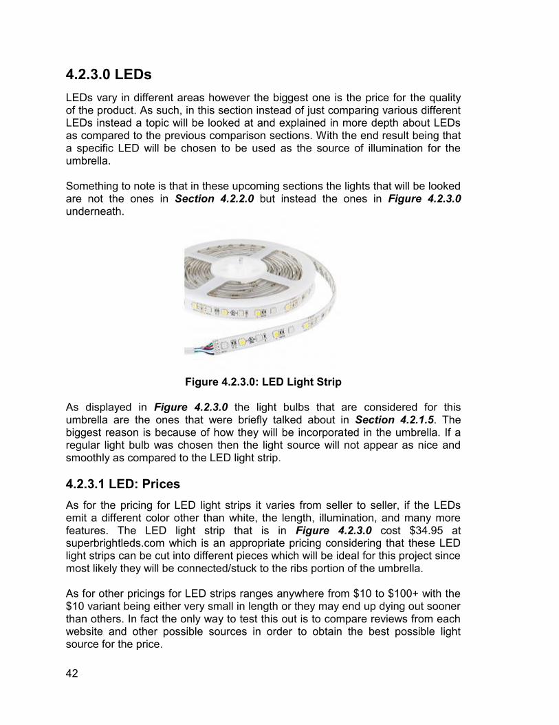
42
4.2.3.0 LEDs LEDs vary in different areas however the biggest one is the price for the quality of the product. As such, in this section instead of just comparing various different LEDs instead a topic will be looked at and explained in more depth about LEDs as compared to the previous comparison sections. With the end result being that a specific LED will be chosen to be used as the source of illumination for the umbrella. Something to note is that in these upcoming sections the lights that will be looked are not the ones in Section 4.2.2.0 but instead the ones in Figure 4.2.3.0 underneath.
Figure 4.2.3.0: LED Light Strip
As displayed in Figure 4.2.3.0 the light bulbs that are considered for this umbrella are the ones that were briefly talked about in Section 4.2.1.5. The biggest reason is because of how they will be incorporated in the umbrella. If a regular light bulb was chosen then the light source will not appear as nice and smoothly as compared to the LED light strip. 4.2.3.1 LED: Prices As for the pricing for LED light strips it varies from seller to seller, if the LEDs emit a different color other than white, the length, illumination, and many more features. The LED light strip that is in Figure 4.2.3.0 cost $34.95 at superbrightleds.com which is an appropriate pricing considering that these LED light strips can be cut into different pieces which will be ideal for this project since most likely they will be connected/stuck to the ribs portion of the umbrella. As for other pricings for LED strips ranges anywhere from $10 to $100+ with the $10 variant being either very small in length or they may end up dying out sooner than others. In fact the only way to test this out is to compare reviews from each website and other possible sources in order to obtain the best possible light source for the price.
43
4.2.3.2 LED: Sizes/Flexibility The LED light strip is the perfect design for the umbrella because it has various areas in which they can be inserted. As explained in the previous section the place in which these LED light strips will be placed in is the ribs however they can be placed in various different areas such as the canopy or even the shaft. However the ribs will be a more ideal place due to the possibility of the umbrella being able to fold and be more portable. Another interesting thing about LEDs is that they also come in the Holiday light decorative variation. The reasoning behind this option is because they can be used and wrapped around the ribs instead of ‘glued’ onto the ribs or canopy portion of the umbrella. This option could be a tad annoying having to deal with all the cables that accompany these Holiday lights with the problem being since the lights are on the cable these cables cannot just be removed or hidden for no apparent reason. A large impact as to the overall design and size of the LED light strip varies a lot by the design of the umbrella itself and the reasoning behind this is because if a traditional umbrella is chosen then there will be more limitations that will be imposed onto the umbrella as to a design that uses less conventional specifications. Such as, making the umbrella be made from harder aluminum or steel. However, a large issue occurs in that the price of the umbrella and the overall pricing of the project will increase a lot because steel and good/hard aluminum is not cheap. Another, problem is that the overall construction of the umbrella would be much harder because instead of just using a regular beach umbrella as the design the umbrella would have to be constructed. It may sound all bad but on the plus side the integration of the LED light strips will be much easier. The way these light strips will be implemented will be discussed in Section 4.2.4.0 and in a more detailed version will be discussed later. 4.2.4.0 Implementation of LED in the Umbrella. In this section only a brief explanation on how the LED lights will be implemented onto the umbrella. However, Section 7.2.0.0 will be going in further details as to how the LED lights will actually be implemented in the umbrella. Instead this section will deal more with a theoretical and which area will be a more ideal location to integrate the lights. There are two ways in which the LED lights will be implemented onto the umbrella. One being the outer layer of the canopy and the other being in the ribs portion. Both have their advantages and disadvantages. These advantages and disadvantages will be discussed in Section 4.2.4.1 and 4.2.4.2 below. In these two sections the scenario in which the umbrella is foldable and not foldable are going too looked into in order to have a better understanding on different possible scenarios.
44
4.2.4.1 Implementation of LED: Canopy When the original vision of implementing lights onto the umbrella apparatus it was intentioned for them to be embedded onto canopy instead of the ribs. As such, there are various different reasons, ideas, and many other things as to why this was the original option. The biggest one being more visibility overall. If the lights were embedded inside with the ribs the amount of visibility would be limited and would not be seen that much by the outside which if this project were to be used in a more social environment like how it was intended to be then having lights only illuminate a given area may not be the best thing in the world. The only way to compensate for the lights to be in the ribs is to have the umbrella size be decently large in order for the lights to be seen by more people. On another note, having the lights on the canopy allows it to look different than other similar projects. Not only would the integration be a tad more annoying for various reason with the main one being money. Since the canopy of an umbrella is fairly large it will require a lengthy LED light strip. As for the cost it may not be such of a problem since LED light strips are not expensive. The only problem there is that if any errors occur during the actual integration or during some other portion of the overall construction of the project. Not only would various actions need to be taken in order to fix this error but there may be chance that putting the light strips back or another set will be a tad more problematic. This is not saying that the ribs will be any better in handling this problem but the canopy will be a little bit more sensitive to solving this problem as compared to the ribs. 4.2.4.1a Implementation of LED: Canopy Æ Foldable To start if the umbrella ends up being foldable there would be many complications when trying to integrate the light strips onto the umbrella for many reasons. The biggest one being delicacy. If the umbrella is not treated delicate in both the demo presentation and the handling in day to day situations the light strips may either fall or get damaged in some way which prevents or limits the source of illumination. Another, and arguably the biggest is dealing with the cables that will connect to the power source. Having any electrical wires hanging around can and is a liability to anyone which means that the wires will not to be handles with in some way in order to prevent them from being exposed while, during the construction phase, allow the lights to be implemented and connected properly with as little wires shown as possible. Overall, implementing the LED light strips onto a foldable umbrella would cause various problems that would only be present and exposed when the construction of the umbrella commences. 4.2.4.1a Implementation of LED: Canopy Æ Non-Foldable In the non-foldable variation the concept of implementing the light strips in would be the best for the simple reason that the integrity of the umbrella would be much more durable as compared to if the umbrella was actually foldable. What this
45
means is that the light strips on umbrella would not have the problem of potential breaking or some other complication that can occur. Another, good thing if the umbrella is not foldable and the lights were implemented on the canopy is that the wires can be hidden in some fashion by implementing some sort of extra cover between the original canopy of the umbrella and a new sheet cover of sorts. Another way is instead of having the umbrella be made of traditional materials the umbrella could very well be made from harder materials such as steel, harder plastic, aluminum, etc. which if any of these materials were to be used in the umbrella it will allow for the wires to be completely hidden because this ‘new sheet’ that would have been added would in turn be an original piece of the umbrella’s overall design. 4.2.4.2 Implementation of LED: Ribs As stated on Section 4.2.4.1 the original idea was to add the lights onto the canopy portion of the umbrella but as time progressed and more research was done on the different variations of lights a conclusion was made that adding them to the ribs portion of the umbrella may not be the worst thing in the world. Especially if a larger size umbrella is being used. Primarily a beach umbrella because they tend to have large ribs that allow the LED light strips previously discussed to be implemented with little to no problems since these ribs. Not only would these LED light strips fit perfectly onto the ribs they would allow for better illumination inside the radius of the umbrella with the only problem is that they would not grant as much illumination to the outside since the light would be downward facing unlike when embedded onto the canopy who would be facing in various directions. However, facing in all directions is a tad problematic because the purpose of the lights is to allow people to see the area/radius in which the umbrella covers since most likely people will be underneath the umbrella while using it. 4.2.4.2a Implementation of LED: Ribs Æ Foldable Another, important decision making regarding as to whether or not the ribs or canopy is better is that if the umbrella ends up being foldable or not. Such as if the umbrella is foldable having the LED lights in the canopy it may cause some problems when folding it because the canopy itself needs to be folded by half for each division most of the times which means that the LED light strips would always be bended when being carried around. Another, problem is that when carrying a beach umbrella sometimes the person carrying is not so careful when dealing with it which means that there are times in which the outside of the umbrella would be hitting something either the ground, if the person is not careful, or another object of sorts. On another note, if the lights were embedded inside the umbrella in the ribs portion they will be a part of the ribs and because the LED light strips are somewhat thin they will be able to fit in the gap between the umbrella’s ribs and shaft. So if someone is carrying the umbrella around the chances of having the LED lights getting ruined or damage is significantly decreased. Another, important aspect of having the LED lights inside in the ribs is in the instance it starts raining. Since, this is an umbrella it means that it will
46
protect the users who are inside of it and everything within the radius of the umbrella including the LED lights that are inside the radius and part of the ribs. 4.2.4.2b Implementation of LED: Ribs Æ Non-Foldable In Section 4.2.4.2a the concept was that the umbrella was foldable while in this section the purpose is if the umbrella is non-foldable. Unlike, the previous section in the instance in which the umbrella is not foldable having them in the canopy may be the best idea because instead of the umbrella being carried around everywhere it will most likely be in one location. However, there are some advantages if the lights are implemented onto the ribs instead and they are that the lights can be a little bigger and brighter since weight should not be as big of an issue because the overall structure of the umbrella is much more durable. But in the instance that the umbrella is not foldable the best idea is to have lights in both the ribs and the canopy simply because it will allow for best illumination and since the umbrella will not be moved around everywhere the structure will be much stronger allowing for more larger solar panels being integrated within the umbrella apparatus. In other words, the power of the umbrella would not be as big of an issue when adding more LED lights which have already been shown to not drain/consume that much power. 4.2.5.0 Other Possible Source of Illumination Just because a specific light bulb was chosen for this project does not mean that it will be the best fit for every single situations. There are some instances in which another light bulb or even form of illumination is superior to the one that was chosen. Prime example, being in an Asian community they may opt out for a small version of their paper lanterns to hang from the umbrella or even those square lanterns with a candle in them that instead of hanging from umbrella could sit in a platform in the inside of the umbrella.
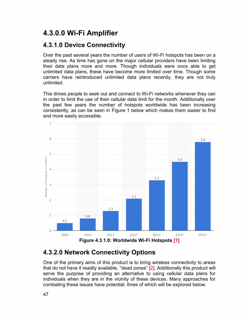
47
4.3.0.0 Wi-Fi Amplifier 4.3.1.0 Device Connectivity Over the past several years the number of users of Wi-Fi hotspots has been on a steady rise. As time has gone on the major cellular providers have been limiting their data plans more and more. Though individuals were once able to get unlimited data plans, these have become more limited over time. Though some carriers have reintroduced unlimited data plans recently, they are not truly unlimited. This drives people to seek out and connect to Wi-Fi networks whenever they can in order to limit the use of their cellular data limit for the month. Additionally over the past few years the number of hotspots worldwide has been increasing consistently, as can be seen in Figure 1 below which makes them easier to find and more easily accessible.
Figure 4.3.1.0: Worldwide Wi-Fi Hotspots [1]
4.3.2.0 Network Connectivity Options One of the primary aims of this product is to bring wireless connectivity to areas that do not have it readily available, “dead zones” [2]. Additionally this product will serve the purpose of providing an alternative to using cellular data plans for individuals when they are in the vicinity of these devices. Many approaches for combating these issues have potential, three of which will be explored below.
48
The sections below will explain the reasoning as to why various areas are to be examined in accordance with choosing the best option. Additionally each area discussed will describe the desired results within their respective areas of comparison. 4.3.2.1 The Requirements The first and quite obvious area of comparison is the connection speed. In an internet connectivity device such as this one the highest speeds are desirable. Any time data has to be received and rebroadcast there is always some “speed loss’ that occurs, but if we start off with a solid and fast connection, that loss of speed will feel less significant to users as their connection will still be fast enough. In essence, a slowed down fast connection, will always feel faster than a slowed down slow connection. If the device is too slow, users will likely move on without actually getting any use out of the product, which would render it pointless. As a result, though there is not a specific numerical value that is being required for speed, the solution selected should be fast. The next area of importance and concern is reliability. That being said this is an area that is difficult to compare effectively seeing as all three options being explored do depend on other devices and circumstances to function as they are intended. As a result this section will address the reliability of these devices under normal and functional conditions. An additional aspect of reliability is to what extent those devices which these potential solutions depend on for connection limit their usability, so that will be explored as well. In a device that is to be completely solar powered energy efficiency is very important. Not only will this portion of the product be powered by the solar energy but also the lights, controllers and the power outlets. As a result efficiency needs to be high and consumption low. Though this may not be an exact comparison, on a general note some forms of wireless communication will use more power than others and that is what will be considered in this section, lowest power consumption. Network security is a factor which can be a cause for concern for many when connecting to data networks. Unsecured networks may allow for hackers to access data from the devices that the users are connecting with, this is unacceptable. Again, an unsecured connection may lead potential users not to use the service provided, again rendering it a waste. As a result, the ability to secure the connection should be a key feature for the option selected.
49
The intention with this device is that it can be taken and set up in a location with limited or no connection, or just to alleviate the strain on personal cell phone data plans. These devices then may be taken and deployed in different location and the setup associated with deploying in a new location is something that could put off a user. This section will explore how easily a device can be deployed and left to do what it is supposed to do and how easy the associated setup is. This is a valuable metric that will aid in the matter at hand. Another important metric that should be considered is cost. These devices are all obviously going to have associated costs for the devices themselves. In addition, some of these devices will also incur a fee for use of service. These costs must be weighed as although a device may be cheaper, if there is a service charge on a repetitive basis they can quickly add up to large numbers which would make the solution less than economical. Lastly, another area that must be considered is the network traffic supporting abilities of these devices and associated connection. These devices will likely draw a large audience and many people will try to connect since they will bring internet connectivity to areas that otherwise would not have it, or at least not as quickly. As a result the solution should be capable of supporting at least a fairly large amount of devices or have a good way of handling multiple connections. 4.3.2.2 Potential Solutions An issue of this nature can be combatted in a variety of ways. The first of these would be to implement a Wi-Fi range extender. These devices are actually quite straightforward in how they work. Within the repeater there are two wireless routers or one working as two. One router will connect to an existing wireless network while the other will transmit the boosted signal. As a result the limitation with a system like this one are that it has to be deployed within range of the existing network. This would make the solution very dependent on existing circumstance and would limit the use of the device to areas with an existing wireless network. That being said, if used and positioned correctly can then be used in order to allow for signal to reach areas past the repeater that would otherwise not have a network available [5]. From this point forward the Wi-Fi repeater solution will be referred to as option A. An alternative option would be to create a hotspot connected to a cellular network. Cellular hotspots have been gaining popularity over the past few years throughout the world. These devices work similarly to a wireless router at home, but they connect to a cellular network rather than directly to a traditional phone line. As a result these devices are more independent than other choices. In addition, due to the nature of their cellular connection these can bring Wi-Fi to
50
more rural areas where local wireless networks do not exist. A potential problem here is the fact that the usability would still be limited to areas where cell phone signal was available. Additionally, signal may be poor “inside a building or in rural locations” causing possible trouble or lack of dependability [3]. From this point forward the cellular hotspot option will be referred to as option B. Lastly, the creation of a satellite based wireless hotspot is a possibility as well. This approach would provide an even greater degree of freedom as the devices could be implemented almost anywhere in the world as long as there is a clear line of sight to the sky in order to maintain connection with the satellite. Also worth noting is that, “in rare instances, extreme weather may affect your signal.” [4] Like option B, this could be used to bring connections to more rural areas where they do not currently exist. From this point forward the satellite hotspot option will be referred to as option C. Each possible solution has many choices for what device to use to implement it. As a result each solution will be analyzed and the top choices for that area will be examined and the best option chosen. These options will then be compared and finally a solution and the device to implement that solution will be chosen accordingly. 4.3.3.0 Examination of Wi-Fi Repeater Options Choosing a Wi-Fi repeater is a task that is to be tackled by referencing 3 lists found online from reputable reviewers of the best range extenders on the market. After examining these 3 lists and choosing the strongest contenders from each the choices will be compared and considerations made. 4.3.3.1 Wi-Fi Repeater Options The initial list examined from tomsguide.com stated that the Netgear Nighthawk Wi-Fi Range Extender AC1900 Desktop WiFi Range Extender (EX7000-100NAS) (router A) was the number one choice [12]. Lifewire regarded the Netgear AC1200 Desktop WiFi Range Extender (EX6200) (router B) as the top choice [13]. The third list examined from Toprateten.com also regarded route A as the ultimate choice and as a result only those two routers will be compared [14]. When choosing a repeater, many considerations were taken into account, in order to select the optimal repeater for the application at hand. Obviously many offerings exist but judging off of the reviews read and the reputations of the websites where this information was gathered, it is believed that these 2 choices are some of the best options on the market at the present time.
51
4.3.3.2 Comparison Many considerations need to be made in order to compare the potential options. One consideration when choosing the repeater for this application is single vs dual band. In essence, the difference here is that while a single band repeater uses one router to both receive and transmit signal, a dual band repeater has 2 routers, one of which is used to receive and the other to broadcast the signal. A single band repeater then is clearly the less efficient option which will result in a lower speed since signal has to be received and then rebroadcast from the same router. This can result in a 50% speed decrease as compared to what can be expected from a dual band repeater that can receive and broadcast simultaneously. Both of the router choices have the advantage of being dual band configured, which is the optimal choice. As a result, there is no obvious winner here. Processor speed also plays a large role in the throughput of Wi-Fi repeaters. The faster the processor the less speed loss we can expect. As a result it would be optimal to choose a repeater with a multi core processor that would not bottleneck the throughput. Router A has a Dual core 1GHz processor in order to optimize Wi-Fi performance but Router B also has an 800GHz dual core processor. As a result, again there is no large advantage in this comparison but router A does take it by a small margin. Dual core processors are very helpful here because they will allow for data to be processed simultaneously in order to be more efficient and minimize speed loss. Another aspect to consider is a dual radio configuration also help to limit the speed loss that may occur. This antenna configuration allows for the device to speak to the main router on lower channels, and then rebroadcast on higher channels. Having one radio receiver and another broadcast allows for boosted signal to utilize a different Wi-Fi channel, which will greatly increase performance compared to that of a single radio application. Again here we see similar dual radio configurations from both possible options and again as a result there isn’t a real standout here. Due to the limitations of the overall product that is being produced size of the wireless repeater does need to be seriously considered. That being said both of the devices in question are basically the same size, in each dimension differing by a maximum of 0.12 inches. As a result, this result is not helpful in choosing the best options for this application. When considering the purchase of anything cost is an important consideration, this is no exception. This must be examined in order to find a cost effective option that accomplishes the required task within the given requirements. Both repeater options are within about $15 of each other so as a result there isn't a
52
massive difference but it is worth noting that router B comes in at a cost of $86.42 while router A comes in at a higher $99.00. Lastly and possibly most importantly, range must be considered. The aim of this product is above all else, to extend the range of a wireless network. In most cases, this means that extending the range of the network would be most effective with the largest possible signal range. As a result the aim here is to find a product with a larger reach of its repeated signal as well as a larger reach to the network being repeated so that it can be placed further away. According to PCmag.com router A maintained a higher average throughput and was significantly faster at varied distances and from both the 5GHz and the 2.4 GHz bands than router B as well as anything else that it was stacked up against [15]. 4.3.3.3 Conclusion Though these two routers ultimately are extremely similar, It seems then that making the best choice comes down to whether the additional range is worth the extra money. Due to not only the added range but also higher throughput speeds, this does make sense for this application. As a result the choice that will be used here is router A, the Netgear Nighthawk AC1900 Desktop WiFi Range Extender (EX7000-100NAS). 4.3.4.0 Examination of Cellular Hotspot Options Choosing a cellular hotspot device is a task that is to be tackled by choosing the top three cellular hotspots as per thewirecutter.com [16] and cnet.com [17], two reputable online review sites for technology products. After determining these three options they will be compared and considerations made. 4.3.4.1 Cellular Hotspot Options The lists of top cellular hotspots on the market that were examined were compiled of a few devices. The top ranking device on both lists is the Jetpack 4G LTE Mobile Hotspot AC791L. The other two devices were both runners up in the two lists examined. These devices are the AT&T Unite Pro and the Novatel Wireless MiFi Liberate. These are all solid products, here their merits will be further explored. In order to compare these products they will be compared in many areas in order to seek out the superior choice for this application. 4.3.4.2 Comparison To begin, as these are mobile hotspot devices they are all fairly small. For our solution the size will not matter much because these are all small enough that they should fit in any enclosure that we create for this. For comparison sake, the Jetpack and the Unite have almost identical dimensions [18][19] while the
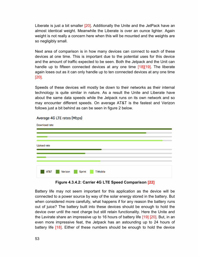
53
Liberate is just a bit smaller [20]. Additionally the Unite and the JetPack have an almost identical weight. Meanwhile the Liberate is over an ounce lighter. Again weight is not really a concern here when this will be mounted and the weights are so negligibly small. Next area of comparison is in how many devices can connect to each of these devices at one time. This is important due to the potential uses for this device and the amount of traffic expected to be seen. Both the Jetpack and the Unit can handle up to fifteen connected devices at any one time [18][19]. The liberate again loses out as it can only handle up to ten connected devices at any one time [20]. Speeds of these devices will mostly be down to their networks as their internal technology is quite similar in nature. As a result the Unite and Liberate have about the same data speeds while the Jetpack runs on its own network and so may encounter different speeds. On average AT&T is the fastest and Verizon follows just a bit behind as can be seen in figure 2 below.
Figure 4.3.4.2: Carrier 4G LTE Speed Comparison [22]
Battery life may not seem important for this application as the device will be connected to a power source by way of the solar energy stored in the battery. But when considered more carefully, what happens if for any reason the battery runs out of juice? The battery built into these devices should be enough to hold the device over until the next charge but still retain functionality. Here the Unite and the Levirate share an impressive up to 16 hours of battery life [19] [20]. But, in an even more impressive feat, the Jetpack has an astounding up to 24 hours of battery life [18]. Either of these numbers should be enough to hold the device
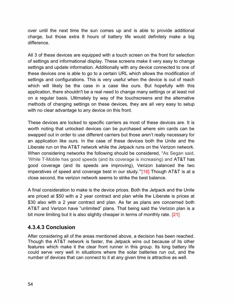
54
over until the next time the sun comes up and is able to provide additional charge, but those extra 8 hours of battery life would definitely make a big difference. All 3 of these devices are equipped with a touch screen on the front for selection of settings and informational display. These screens make it very easy to change settings and update information. Additionally with any device connected to one of these devices one is able to go to a certain URL which allows the modification of settings and configurations. This is very useful when the device is out of reach which will likely be the case in a case like ours. But hopefully with this application, there shouldn't be a real need to change many settings or at least not on a regular basis. Ultimately by way of the touchscreens and the alternative methods of changing settings on these devices, they are all very easy to setup with no clear advantage to any device on this front. These devices are locked to specific carriers as most of these devices are. It is worth noting that unlocked devices can be purchased where sim cards can be swapped out in order to use different carriers but those aren’t really necessary for an application like ours. In the case of these devices both the Unite and the Liberate run on the AT&T network while the Jetpack runs on the Verizon network. When considering networks the following should be considered, “As Segan said, ‘While T-Mobile has good speeds (and its coverage is increasing) and AT&T has good coverage (and its speeds are improving), Verizon balanced the two imperatives of speed and coverage best in our study.’”[16] Though AT&T is at a close second, the verizon network seems to strike the best balance. A final consideration to make is the device prices. Both the Jetpack and the Unite are priced at $50 with a 2 year contract and plan while the Liberate is prices at $30 also with a 2 year contract and plan. As far as plans are concerned both AT&T and Verizon have “unlimited” plans. That being said the Verizon plan is a bit more limiting but it is also slightly cheaper in terms of monthly rate. [21] 4.3.4.3 Conclusion After considering all of the areas mentioned above, a decision has been reached. Though the AT&T network is faster, the Jetpack wins out because of its other features which make it the clear front runner in this group. Its long battery life could serve very well in situations where the solar batteries run out, and the number of devices that can connect to it at any given time is attractive as well.
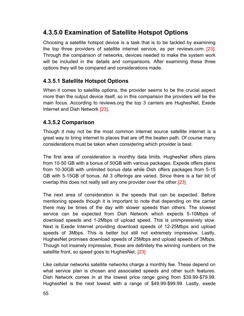
55
4.3.5.0 Examination of Satellite Hotspot Options Choosing a satellite hotspot device is a task that is to be tackled by examining the top three providers of satellite internet service, as per reviews.com [23]. Through the comparison of networks, devices needed to make the system work will be included in the details and comparisons. After examining these three options they will be compared and considerations made. 4.3.5.1 Satellite Hotspot Options
When it comes to satellite options, the provider seems to be the crucial aspect more than the output device itself, so in this comparison the providers will be the main focus. According to reviews.org the top 3 carriers are HughesNet, Exede Internet and Dish Network [23]. 4.3.5.2 Comparison Though it may not be the most common internet source satellite internet is a great way to bring internet to places that are off the beaten path. Of course many considerations must be taken when considering which provider is best. The first area of consideration is monthly data limits. HughesNet offers plans from 10-50 GB with a bonus of 50GB with various packages. Expede offers plans from 10-30GB with unlimited bonus data while Dish offers packages from 5-15 GB with 5-15GB of bonus. All 3 offerings are varied. Since there is a fair bit of overlap this does not really sell any one provider over the other.[23] The next area of consideration is the speeds that can be expected. Before mentioning speeds though it is important to note that depending on the carrier there may be times of the day with slower speeds than others. The slowest service can be expected from Dish Network which expects 5-10Mbps of download speeds and 1-2Mbps of upload speed. This is unimpressively slow. Next is Exede Internet providing download speeds of 12-25Mbps and upload speeds of 3Mbps. This is better but still not extremely impressive. Lastly, HughesNet promises download speeds of 25Mbps and upload speeds of 3Mbps. Though not insanely impressive, those are definitely the winning numbers on the satellite front, so speed goes to HughesNet. [23] Like cellular networks satellite networks charge a monthly fee. These depend on what service plan is chosen and associated speeds and other such features. Dish Network comes in at the lowest price range going from $39.99-$79.99. HughesNet is the next lowest with a range of $49.99-$99.99. Lastly, exede
56
comes in with a range of $49.9-$149.99. Exede’s range is largest because they offer a broader range of services at an optional upcharge. [23] Additional to the service cost, these companies also rent you equipment that is required for the use of their services such as modems. Without these devices there would be no way to access your internet connection. These prices are usually fairly low but they are a monthly fee added to your bill. Exede and Dish Network both charge $9.99 per month for the equipment fee. HughesNet on the other hand charges $14.00 per month. Though not a massive difference that could add up rather quickly. [23]
Figure 4.3.5.2: Top 3 Satellite Internet Providers [23]
4.3.5.3 Conclusion This comparison was the closest of the three choices needing to be made. Each of these companies has their own pros and cons. That being said the most compelling of the three was decidedly HughesNet. First off their threshold for data at the highest level was the only one that seemed like enough for the need that excited in this product. The max download and upload speeds sold it well as well as they were higher than other alternatives. Even though the equipment fee was higher than the competition for the performance from HughesNet from Exede the final due amount would have been higher anyways, so this was the best bang for buck for the desired services and results.
57
4.3.6.0 Examination of Solutions These three options are all plausible and realistic solutions to the issue at hand. Below these three will be examined in further detail in order to determine which solution will be implemented in this device. Note that these assessment will be based on the device chosen above for each of the solutions discussed. 4.3.6.1 Option A: Wi-Fi Range Extender When implementing a Wi-Fi Range Extender, the connection speed is very much dependent on the network which the device will be repeating as well as the distance from the router which is giving off the network signal. That being said, wireless repeaters have become quite advanced and many have safeguards in place to overcome some common issues with common causes of speed loss from the past. For example, dual radios, dual bands, faster processors [5]. These are all examples of advancements that have come about in the past few years which help the speed of these devices. As time goes on wired connections are getting faster so in theory over time this type of connection should continue to speed up with the networks that it emulates. With an application that relies as heavily on another Wi-Fi network to operate as option A, reliability is very much dependent on that connection. As reliable as the repeater is, if the host network goes down or is obstructed the network goes down. That being said, the configuration of our device means that once deployed it will not be moving, so if a network exists and reaches the location where the device will be placed, it is unlikely that the connection will be lost. As a result, the connection should be for the most part reliable, again with the small stipulation that if the host network goes down for any reason the repeated connection goes down as well. The solar panel that will power this project will only be able to bring in so much energy and the battery where the energy it stored is only so large. Though daytime use may not be a huge concern, but use when there is no sunlight feeding the battery must also be considered. As a result lower power consumption would be ideal. Since these devices have no physical moving parts they are quite efficient and do not use much power. According to energyusecalculator.com a typical router uses between 2 and 20 watts per day on average, and a device like this one falls on the upper end of that scale [9]. When extending an existing wireless network the ideal situation would result in the same security of the existing wireless network to be transferred to the new network. There are two potential security approaches here. First, if the host network is a transitional home type network then the repeated network security will be configurable on the device and can be setup with various password protection options or can be left without a password regardless of the way the host is setup. The other option is in the case of an institution where there is an
58
authentication process and certificate associated like a University of Workplace network. In these cases the network itself won’t have any password associated but to do anything on the network you'll have to authenticate just like you would on the original network. In terms of security of connection this would provide as safe a connection as that on a traditional Wi-Fi network. As a result this seems like an ideal security situation. Most wireless networking devices will save their prior configuration in case they are turned off or lose power and the next time they are turned on they will just default back to their prior configuration. The repeater is no exception. This is clearly ideal because when we move a device around the same area to deploy elsewhere, if it is already configured for that local network there is minimal work to do other than physically moving the device. All that would need to be done is turn the device on and that's it. Regarding initial setup, it's as easy as signing into the repeater with a secure username and password and configuring for the desired settings. Cost considerations for a Wi-Fi repeater are fairly reasonable. The price of the hardware itself can range anywhere from around $50 to around $150. Devices come in all shapes, colors, sizes and configuration. Luckily the hardware price is all you technically have to pay for an application like this as the individual who pays for the internet bill will already be paying that bill no matter if the repeater is being used or not. As a result, this is a very cost effective solution. Most wireless routers can handle around 250 devices at any one time. That being said one router is only rated for certain levels of bandwidth. Every device that is connected to that network will split that connection further and further and slow down the overall speed of each connected device. Hence, a wireless repeater is able to handle a slightly smaller number of devices at any given time so this slowdown should be less severe. This device is definitely able to support a higher load than that of option B but should be similar to that of option C. 4.3.6.2 Option B: Cellular Hotspot Cellular data speeds have been on the constant rise over the past couple of years. At this point it is possible to find Wi-Fi speed cellular connections with the right hardware and network to match. For the purpose of cellular hotspots speeds should mirror what can be seen on mobile phones on the same cellular networks with similar hardware. As time goes on and cellular network speeds increase, unfortunately option B’s speeds would not adapt with the changes. Unfortunately this is because in most cases in order to take advantage of new technologies and speeds, new hardware is required which would be an additional charge and more so additional labor and installation every few years [6]. All that said, cellular data speeds are pretty high though usually lower than those of Wi-Fi connections so this is a viable speed option.
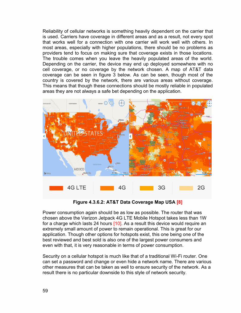
59
Reliability of cellular networks is something heavily dependent on the carrier that is used. Carriers have coverage in different areas and as a result, not every spot that works well for a connection with one carrier will work well with others. In most areas, especially with higher populations, there should be no problems as providers tend to focus on making sure that coverage exists in those locations. The trouble comes when you leave the heavily populated areas of the world. Depending on the carrier, the device may end up deployed somewhere with no cell coverage, or no coverage by the network chosen. A map of AT&T data coverage can be seen in figure 3 below. As can be seen, though most of the country is covered by the network, there are various areas without coverage. This means that though these connections should be mostly reliable in populated areas they are not always a safe bet depending on the application.
Figure 4.3.6.2: AT&T Data Coverage Map USA [8]
Power consumption again should be as low as possible. The router that was chosen above the Verizon Jetpack 4G LTE Mobile Hotspot takes less than 1W for a charge which lasts 24 hours [10]. As a result this device would require an extremely small amount of power to remain operational. This is great for our application. Though other options for hotspots exist, this one being one of the best reviewed and best sold is also one of the largest power consumers and even with that, it is very reasonable in terms of power consumption. Security on a cellular hotspot is much like that of a traditional Wi-Fi router. One can set a password and change or even hide a network name. There are various other measures that can be taken as well to ensure security of the network. As a result there is no particular downside to this style of network security.
60
Ease of access for the cellular hotspot is one of its great aspects. Since this network always connects to the same cellular network there is no need to configure when relocating. All that needs to be done is the device needs to be turned on and that's it. Once the connection is made it should be useable instantly. Regarding configuration of device settings, this device has a screen and controls right on the device and that is where configurations are made. Cellular network hotspots usually have a device charge associated with the device which is usually a small fee. In the case of the device that is being examined as a choice here the price was $49 with a 2 year contract. This price isn't really too bad but with this sort of device we do have to consider the monthly service fee. A plan comparable to what would be expected to be used would cost just under $100 per month [10]. This would very quickly add up to an unsupportable level. Lastly, with regards to network traffic support, here and LTE network is considered=as it will be most competitive with a Wi-Fi connection. At busy events such as football games or music festivals where a large amount of people are all attempting to connect to the same network users may find it hard to connect. If the device is able to connect to the antenna it may still have a very low speed connection because so many devices are connected to the network resulting in those connected devices needing to share the abilities of that data source, its bandwidth. Other than those limitations, the device being considered can support up to 15 devices at any one time [10]. This is a pretty low number but should be enough for this application. 4.3.6.3 Option C: Satellite Hotspot Satellite hotspots remain significantly less tested than the other two options, at least in the size and configuration that would make sense for this application. There are many reasons for this which will be discussed below but regarding speeds, they tend to be a bit higher than cellular hotspots but lower than those of Wi-Fi. On average, speeds around 15 Mbps can be expected according to reviews.org [7]. This makes it the faster of the two more independent options, so depending on the application, this could be a great option based on speed. Similarly to reliability of cellular hotspots, option C depends heavily on being able to connect clearly and correctly with the satellites. Depending on the provider dependability will vary but the biggest hurdle for reliability here would be that “you must have an unobstructed southward view of the sky” [7]. Unfortunately, this is not always possible especially with a mobile device that can be placed in various locations. Though one can try and always place it where there is a clear line of sight, it is not a guaranteed availability. As a result, this may not be the best option for this application. Unfortunately power consumption is not one of the strong points of the satellite hotspot option. According to offgridsurvival.com while a satellite model is turned
61
on it will continue to draw 20-30 watts of power which is higher than would be ideal, especially because the idea with a solution like this one is to leave it on round the clock once it is deployed [11]. This is definitely a large potential drawback to keep in mind. Security for a satellite hotspot network is again very similar to a traditional home network type setup. Once the data is received it is distributed by a fairly normal Wi-Fi router so it can be configured as such and any normal security options and configurations would be available. This again makes it as safe as any other network and the more securely it is configured the safer it will be. Like the other two options, this device will remember how it was set up last time it was powered on so there is no need to reconfigure every time the device is moved unless a problem is encountered. With regard to the device setup, it is treated like that of any other standard route. Network name and visibility can be changed as well as passwords and other settings. The HughesNet service that is being considered the winning choice of the option C section has a monthly service fee but also has a device fee of around $15 per month. The service fee is then an additional $49 to $99 depending on small variations in the options [7]. This would again quickly add up like option B. As a result this isn't an ideal situation. As stated prior the device associated with this solution is essentially just a normal router. This means that like option A it can handle a high number of devices, somewhere in the neighborhood of 250. That being said the more devices that connect the slower the connection gets for everyone connected. So as much as you can load this network up with users it would not be advisable to connect a huge amount of devices to the network. 4.3.6.4 Conclusion In the arena of speed, these options all yield pretty solid results for their respective technologies. That being said there is definite tradeoffs seen between features, cost, etc. for higher speeds. In terms of outright speeds though option A is the clear winner. Not that the other two aren't very respectable options, but they are just not the hands down fastest. Reliability is an area where all three options face some obstacles. Though some could be seen as more independent than others, none is perfectly reliable. That being said, this one really depends on the application of the device. If the device is to be used somewhere that Wi-Fi connections are available to connect to, then option A wins out. If there is an area that does not have an existing network and is not obstructed by trees or buildings then option C would win out. But in the case where there is no network and there is a bit more distortion by surroundings, option B would be optimal.
62
Power consumption with an implementation that is solar energy based is extremely important, as stated prior. Option B clearly is the winner of this segment as it uses a miniscule amount of power compared to option C and some amount less than option B. That being said option B would also be an appropriate choice for this. Security across all three solutions has the potential to be as secure as should be needed. The common stipulation is that the network is set up securely with a strong password and even being set up to be hidden so that random individuals cannot find it. A security advantage exists for option A in the case of expanding an existing network with an internal net type situation because users would still have access to that internal net even when logged in from the repeater. Since this is not a particularly important functionality unless that is the application to be used the three options rank similarly in this category and there is no clear victor. With regard to ease of deployment all three options are pretty easy. Options A and C are the most complicated for initial configuration because they require connecting to the device and then going to a certain configuration web address where these changes can be made. That being said once that is done they are very easy to set and forget. That said, option B is the easiest because to change configurations you can just work directly on the screen of the device. But it is also worth noting that this means that to change configurations, the device will physically need to be removed. On the other hand the other two options allow changes to configuration to be made from a computer connected to the network which makes much more sense. Cost wise options B and C are problematic in the long run due to their repetitive monthly fee. Even though the initial costs for the hardware are lower, this is quickly nullified by the expensive monthly plans. Option A on the other hand takes the monthly fee out of the equation due to the fact that with or without this service that internet will still be paid for, so this does not really change anything. Otherwise no usage fee is associated and as a result this is the winning choice for cost. How many users a device can handle is very important for an application like this one because obviously being a public network it needs to be able to handle heavy traffic. Option B is not a great option because of this reason. Being limited to 15 devices means that many will likely be left without a connection. Options A and C both act basically as normal routers so they can handle many devices but again that does not mean that they should have so many devices connecting to them as each one takes more and more bandwidth causing a massive slowdown of service. As a result options A and C win out.
63
4.3.7.0 Device Selection, Installation & Configuration 4.3.7.1 Making the Selection After considering all of the above information all three options have their definite advantages and disadvantages but the breakdown is as follows. In third place would be the option B, the cellular hotspot. This is due to the limited number of users and high monthly cost for the most part. The runner up is then option C, satellite hotspot. Though speeds were promising and the user numbers were favorable the high monthly cost and power consumption. This makes option A, Wi-Fi repeater the top choice for this application. Though it is not a perfect solution it is the best solution that could be found. Because we have selected solution A the device to be implemented is the Netgear Nighthawk Wi-Fi Range Extender AC1900 Desktop Wi-Fi Range Extender (EX7000-100NAS). Additionally the decision has been made that the main aim for this device will be to implement it on campuses or other locations where a common wireless network is present throughout the area across multiple Wi-Fi routers. This will allow for the positioning of the device at a variety of locations to fill gaps in the network. This will not only be a huge help for the students but also for the professors and other staff of these universities. 4.3.7.2 Potential Issues Unfortunately, as with any solution there are some potential problems that would render this solution less useful than would be idea. One such issue is that a wireless device would only connect to a Wi-Fi repeater after it has lost connection from the original source of Wi-Fi. This might cause low signal at the edges of the original network before disconnecting and then connecting to the repeater instead. Though this should not be a huge deal it may cause some discomfort to the users in various cases and momentary downtime and interruption in service. Another concerns is the speed loss that will inevitably occur. This is something that will always occur with a repeater as the system must receive the signal and then broadcast it back out, which does not happen instantly. That being said the repeater chosen above was chosen because it is one that should minimally limit the speed of the rebroadcast connection and as a result provide the fastest connection possible for such a configuration. 4.3.7.3 Installation Installation and setup of a device is rather simple. In our case our system would be deployed in various locations such as campus or something along those lines where the same network is used all around the area, we should be able to configure the system once and deploy it anywhere on the edges of range. The network configuration will then be set up by logging in to the repeater, signing in
64
with a secure login and password and then configuring it for the network that we want to extend the range of. 4.3.7.4 Configuration The initial configuration is to be done one time when first setting up the repeater. The device must be connected to an AC outlet and then powered on. Once the device boots up which should only take a moment the individual configuring the system should use an internet connected device such as a laptop, cellphone, tablet, etc. Using this device the configurator should search for a network called “NETGEAR_EXT” and connect to it when found. Once connected a webpage will automatically be pulled up with a button reading “New Extender Setup” this is to be clicked. Next account creation information will come up. This is to be filled in with an email, password and security questions which will be used later for any configuration of the range extender. As a result an email and password should be used that would be accessible to anyone needing to alter the settings for the extender. Once the account is successfully created a question will come up regarding how the user would like to use the extender. The options are “WIFI RANGE EXTENDER” and “ACCESS POINT”. The first mode is used in order to boost the range of an existing Wi-Fi network. The latter option can be used when physically connected to a wired router and then broadcasting a signal. This basically works in accordance with a wired router to create a wireless connection. In This case the user should select the “WIFI RANGE EXTENDER” option. Next the user will be able to select which wireless networks should be extended with the device. This can be with up to 2 networks, one 2.4 GHz Wi-Fi network and the other a 5GHz Wi-Fi network. The page lists them in respective lists, one can be selected by each. Once done, “NEXT” button should be clicked. The user will then be prompted to enter a password for both of the selected networks individually. The 2.4GHz network will come up first and after entering the password the “NEXT” button should be pressed. Next the 5GHz network will come up and after the password is entered the “NEXT” button should be pressed. Finally, the network names and security settings for the extended Wi-Fi networks are then to be chosen. The 2.4GHz network and the 5GHz network are listed on the same page. The names for both networks should then be entered. These are the names of the networks that will be seen by the devices trying to connect to them. In the case of a campus connection extension, the name of the campus network should be used in order to extend said network. The security settings should also be set underneath the name fields. These should again be consistent with those settings if we are extending an existing network, and the setting “Same as existing network password” should be chosen. Then “NEXT” is selected.
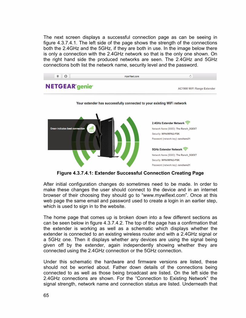
65
The next screen displays a successful connection page as can be seeing in figure 4.3.7.4.1. The left side of the page shows the strength of the connections both the 2.4GHz and the 5GHz, if they are both in use. In the image below there is only a connection with the 2.4GHz network so that is the only one shown. On the right hand side the produced networks are seen. The 2.4GHz and 5GHz connections both list the network name, security level and the password.
Figure 4.3.7.4.1: Extender Successful Connection Creating Page
After initial configuration changes do sometimes need to be made. In order to make these changes the user should connect to the device and in an internet browser of their choosing they should go to “www.mywifiext.com”. Once at this web page the same email and password used to create a login in an earlier step, which is used to sign in to the website. The home page that comes up is broken down into a few different sections as can be seen below in figure 4.3.7.4.2. The top of the page has a confirmation that the extender is working as well as a schematic which displays whether the extender is connected to an existing wireless router and with a 2.4GHz signal or a 5GHz one. Then it displays whether any devices are using the signal being given off by the extender, again independently showing whether they are connected using the 2.4GHz connection or the 5GHz connection. Under this schematic the hardware and firmware versions are listed, these should not be worried about. Father down details of the connections being connected to as well as those being broadcast are listed. On the left side the 2.4GHz connections are shown. For the “Connection to Existing Network” the signal strength, network name and connection status are listed. Underneath that
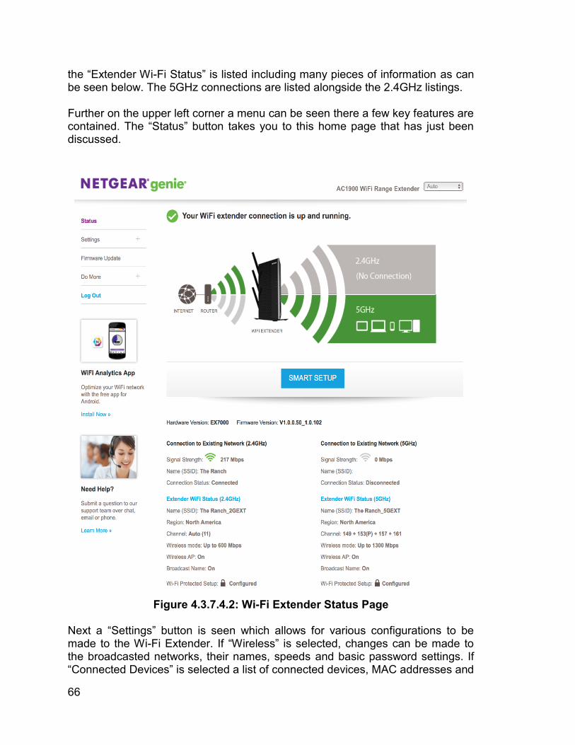
66
the “Extender Wi-Fi Status” is listed including many pieces of information as can be seen below. The 5GHz connections are listed alongside the 2.4GHz listings. Further on the upper left corner a menu can be seen there a few key features are contained. The “Status” button takes you to this home page that has just been discussed.
Figure 4.3.7.4.2: Wi-Fi Extender Status Page
Next a “Settings” button is seen which allows for various configurations to be made to the Wi-Fi Extender. If “Wireless” is selected, changes can be made to the broadcasted networks, their names, speeds and basic password settings. If “Connected Devices” is selected a list of connected devices, MAC addresses and
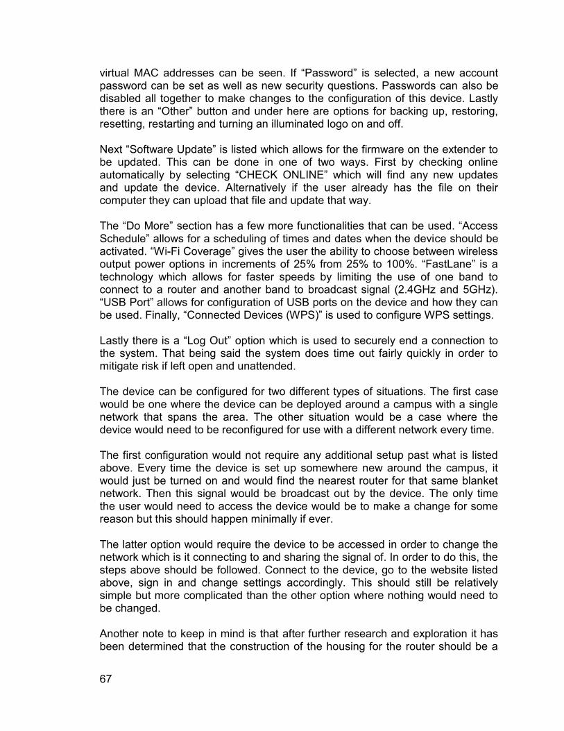
67
virtual MAC addresses can be seen. If “Password” is selected, a new account password can be set as well as new security questions. Passwords can also be disabled all together to make changes to the configuration of this device. Lastly there is an “Other” button and under here are options for backing up, restoring, resetting, restarting and turning an illuminated logo on and off. Next “Software Update” is listed which allows for the firmware on the extender to be updated. This can be done in one of two ways. First by checking online automatically by selecting “CHECK ONLINE” which will find any new updates and update the device. Alternatively if the user already has the file on their computer they can upload that file and update that way. The “Do More” section has a few more functionalities that can be used. “Access Schedule” allows for a scheduling of times and dates when the device should be activated. “Wi-Fi Coverage” gives the user the ability to choose between wireless output power options in increments of 25% from 25% to 100%. “FastLane” is a technology which allows for faster speeds by limiting the use of one band to connect to a router and another band to broadcast signal (2.4GHz and 5GHz). “USB Port” allows for configuration of USB ports on the device and how they can be used. Finally, “Connected Devices (WPS)” is used to configure WPS settings. Lastly there is a “Log Out” option which is used to securely end a connection to the system. That being said the system does time out fairly quickly in order to mitigate risk if left open and unattended. The device can be configured for two different types of situations. The first case would be one where the device can be deployed around a campus with a single network that spans the area. The other situation would be a case where the device would need to be reconfigured for use with a different network every time. The first configuration would not require any additional setup past what is listed above. Every time the device is set up somewhere new around the campus, it would just be turned on and would find the nearest router for that same blanket network. Then this signal would be broadcast out by the device. The only time the user would need to access the device would be to make a change for some reason but this should happen minimally if ever. The latter option would require the device to be accessed in order to change the network which is it connecting to and sharing the signal of. In order to do this, the steps above should be followed. Connect to the device, go to the website listed above, sign in and change settings accordingly. This should still be relatively simple but more complicated than the other option where nothing would need to be changed. Another note to keep in mind is that after further research and exploration it has been determined that the construction of the housing for the router should be a
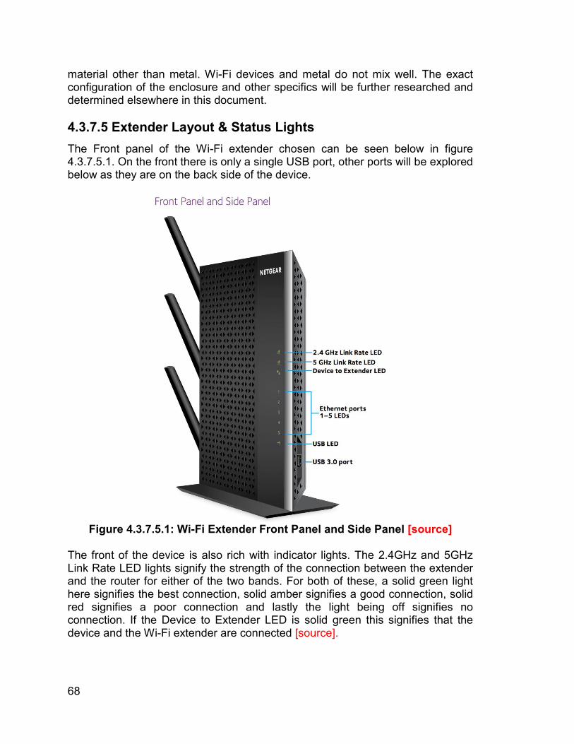
68
material other than metal. Wi-Fi devices and metal do not mix well. The exact configuration of the enclosure and other specifics will be further researched and determined elsewhere in this document. 4.3.7.5 Extender Layout & Status Lights The Front panel of the Wi-Fi extender chosen can be seen below in figure 4.3.7.5.1. On the front there is only a single USB port, other ports will be explored below as they are on the back side of the device.
Figure 4.3.7.5.1: Wi-Fi Extender Front Panel and Side Panel [source]
The front of the device is also rich with indicator lights. The 2.4GHz and 5GHz Link Rate LED lights signify the strength of the connection between the extender and the router for either of the two bands. For both of these, a solid green light here signifies the best connection, solid amber signifies a good connection, solid red signifies a poor connection and lastly the light being off signifies no connection. If the Device to Extender LED is solid green this signifies that the device and the Wi-Fi extender are connected [source].
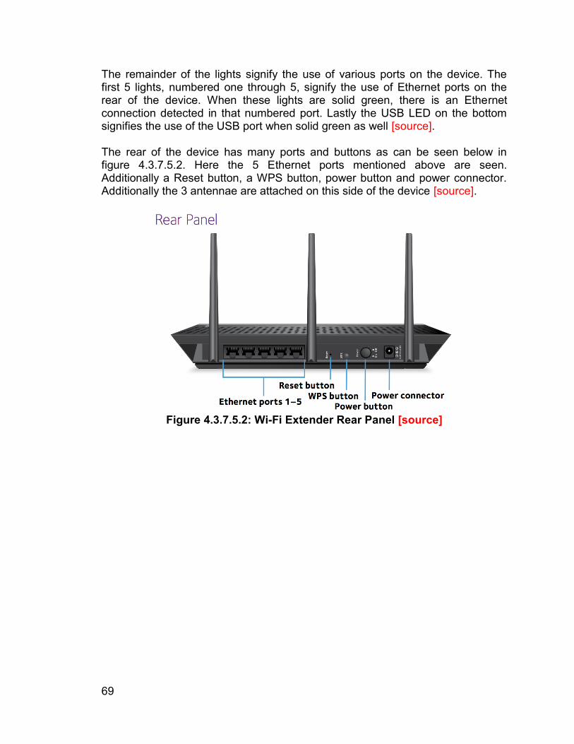
69
The remainder of the lights signify the use of various ports on the device. The first 5 lights, numbered one through 5, signify the use of Ethernet ports on the rear of the device. When these lights are solid green, there is an Ethernet connection detected in that numbered port. Lastly the USB LED on the bottom signifies the use of the USB port when solid green as well [source]. The rear of the device has many ports and buttons as can be seen below in figure 4.3.7.5.2. Here the 5 Ethernet ports mentioned above are seen. Additionally a Reset button, a WPS button, power button and power connector. Additionally the 3 antennae are attached on this side of the device [source].
Figure 4.3.7.5.2: Wi-Fi Extender Rear Panel [source]
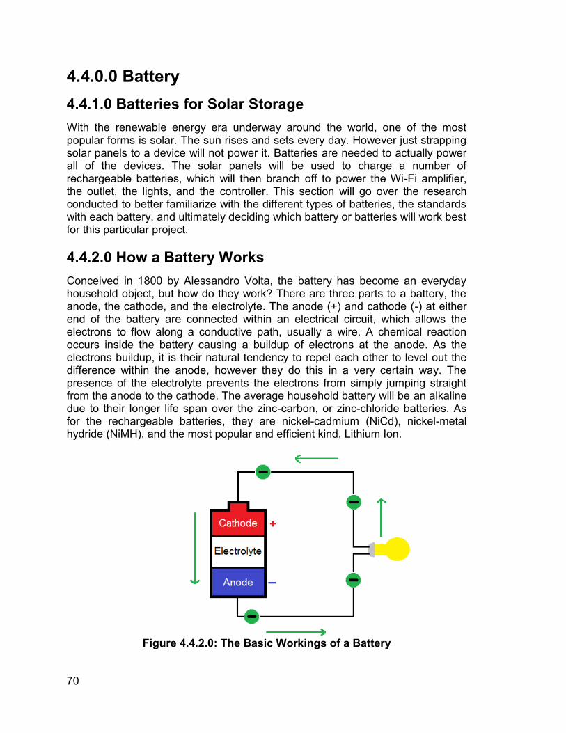
70
4.4.0.0 Battery 4.4.1.0 Batteries for Solar Storage With the renewable energy era underway around the world, one of the most popular forms is solar. The sun rises and sets every day. However just strapping solar panels to a device will not power it. Batteries are needed to actually power all of the devices. The solar panels will be used to charge a number of rechargeable batteries, which will then branch off to power the Wi-Fi amplifier, the outlet, the lights, and the controller. This section will go over the research conducted to better familiarize with the different types of batteries, the standards with each battery, and ultimately deciding which battery or batteries will work best for this particular project. 4.4.2.0 How a Battery Works Conceived in 1800 by Alessandro Volta, the battery has become an everyday household object, but how do they work? There are three parts to a battery, the anode, the cathode, and the electrolyte. The anode (+) and cathode (-) at either end of the battery are connected within an electrical circuit, which allows the electrons to flow along a conductive path, usually a wire. A chemical reaction occurs inside the battery causing a buildup of electrons at the anode. As the electrons buildup, it is their natural tendency to repel each other to level out the difference within the anode, however they do this in a very certain way. The presence of the electrolyte prevents the electrons from simply jumping straight from the anode to the cathode. The average household battery will be an alkaline due to their longer life span over the zinc-carbon, or zinc-chloride batteries. As for the rechargeable batteries, they are nickel-cadmium (NiCd), nickel-metal hydride (NiMH), and the most popular and efficient kind, Lithium Ion.
Figure 4.4.2.0: The Basic Workings of a Battery
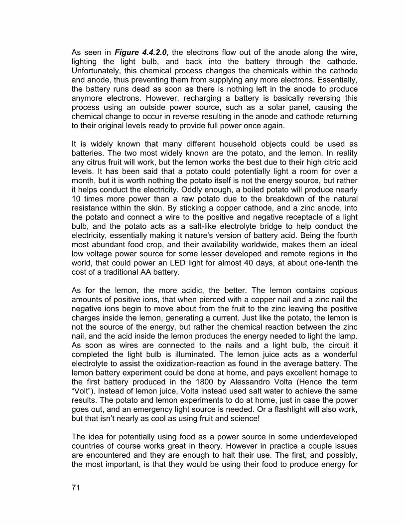
71
As seen in Figure 4.4.2.0, the electrons flow out of the anode along the wire, lighting the light bulb, and back into the battery through the cathode. Unfortunately, this chemical process changes the chemicals within the cathode and anode, thus preventing them from supplying any more electrons. Essentially, the battery runs dead as soon as there is nothing left in the anode to produce anymore electrons. However, recharging a battery is basically reversing this process using an outside power source, such as a solar panel, causing the chemical change to occur in reverse resulting in the anode and cathode returning to their original levels ready to provide full power once again. It is widely known that many different household objects could be used as batteries. The two most widely known are the potato, and the lemon. In reality any citrus fruit will work, but the lemon works the best due to their high citric acid levels. It has been said that a potato could potentially light a room for over a month, but it is worth nothing the potato itself is not the energy source, but rather it helps conduct the electricity. Oddly enough, a boiled potato will produce nearly 10 times more power than a raw potato due to the breakdown of the natural resistance within the skin. By sticking a copper cathode, and a zinc anode, into the potato and connect a wire to the positive and negative receptacle of a light bulb, and the potato acts as a salt-like electrolyte bridge to help conduct the electricity, essentially making it nature's version of battery acid. Being the fourth most abundant food crop, and their availability worldwide, makes them an ideal low voltage power source for some lesser developed and remote regions in the world, that could power an LED light for almost 40 days, at about one-tenth the cost of a traditional AA battery. As for the lemon, the more acidic, the better. The lemon contains copious amounts of positive ions, that when pierced with a copper nail and a zinc nail the negative ions begin to move about from the fruit to the zinc leaving the positive charges inside the lemon, generating a current. Just like the potato, the lemon is not the source of the energy, but rather the chemical reaction between the zinc nail, and the acid inside the lemon produces the energy needed to light the lamp. As soon as wires are connected to the nails and a light bulb, the circuit it completed the light bulb is illuminated. The lemon juice acts as a wonderful electrolyte to assist the oxidization-reaction as found in the average battery. The lemon battery experiment could be done at home, and pays excellent homage to the first battery produced in the 1800 by Alessandro Volta (Hence the term “Volt”). Instead of lemon juice, Volta instead used salt water to achieve the same results. The potato and lemon experiments to do at home, just in case the power goes out, and an emergency light source is needed. Or a flashlight will also work, but that isn’t nearly as cool as using fruit and science! The idea for potentially using food as a power source in some underdeveloped countries of course works great in theory. However in practice a couple issues are encountered and they are enough to halt their use. The first, and possibly, the most important, is that they would be using their food to produce energy for
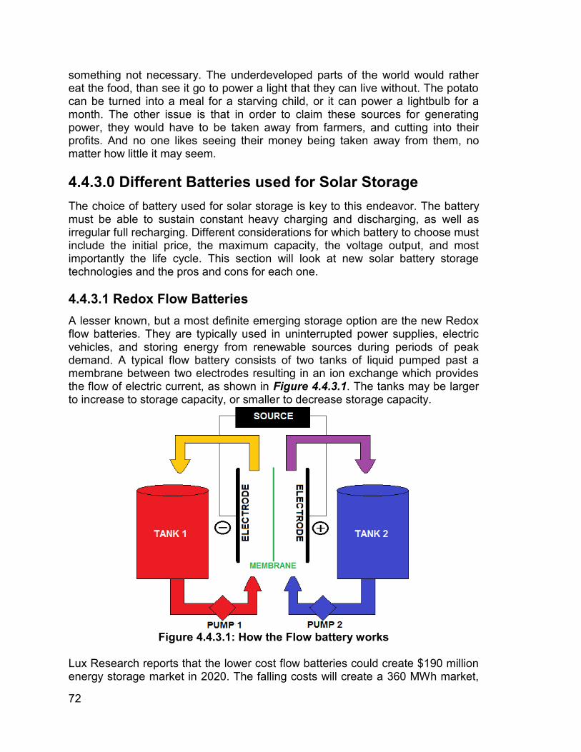
72
something not necessary. The underdeveloped parts of the world would rather eat the food, than see it go to power a light that they can live without. The potato can be turned into a meal for a starving child, or it can power a lightbulb for a month. The other issue is that in order to claim these sources for generating power, they would have to be taken away from farmers, and cutting into their profits. And no one likes seeing their money being taken away from them, no matter how little it may seem. 4.4.3.0 Different Batteries used for Solar Storage The choice of battery used for solar storage is key to this endeavor. The battery must be able to sustain constant heavy charging and discharging, as well as irregular full recharging. Different considerations for which battery to choose must include the initial price, the maximum capacity, the voltage output, and most importantly the life cycle. This section will look at new solar battery storage technologies and the pros and cons for each one. 4.4.3.1 Redox Flow Batteries A lesser known, but a most definite emerging storage option are the new Redox flow batteries. They are typically used in uninterrupted power supplies, electric vehicles, and storing energy from renewable sources during periods of peak demand. A typical flow battery consists of two tanks of liquid pumped past a membrane between two electrodes resulting in an ion exchange which provides the flow of electric current, as shown in Figure 4.4.3.1. The tanks may be larger to increase to storage capacity, or smaller to decrease storage capacity.
Figure 4.4.3.1: How the Flow battery works
Lux Research reports that the lower cost flow batteries could create $190 million energy storage market in 2020. The falling costs will create a 360 MWh market,
73
led by vanadium-based systems with the vanadium redox flow battery (VRFB) [1]. Due to its still relatively new life, and rather complicated chemistry, the cost for the VRFB is still on the higher side. According to its developers, sourcing vanadium from fly ash (a byproduct of coal-fired electric generating plants) could reduce the costs from over $500/kWh to $300/kWh potentially by 2024 [1]. The great thing about this, is how plentiful, and cheap coal is in today’s economy. If a harmful byproduct of burning coal can be turned into something useful everyone wins. The developers are working on a way to increase the power density, which in turn drives down the cost. One of the biggest benefactors for the flow batteries, is that they will not deteriorate over time, making them last much longer than the direct competition of Lithium ions. Also, with many other batteries, adding more is the only way to get more power output, but with the flow batteries, simply adding more electrolytes will give more power. Meaning only one has to be bought, installed, and it can be set to the user preference. One of the truly amazing things about the flow batteries is that the repeated charging and discharging has no impact on the life cycle. Meaning it can be used as often, and as long as needed without any kind of penalty. Flow batteries are made more for the large scale power storage, such as a solar farm or plant. The large size and storage capacity of the tanks make this method ideal for powering large projects or grids. Due to its still relatively new life, the flow battery still must become smaller to become more practical for everyday use. 4.4.3.2 Lead-Acid Batteries The lead-acid battery has been used in renewable energy, and in off-grid applications for decades (think a car, golf cart, or a home security battery backup). The lead-acid batteries do not produce a voltage on their own, but rather they only store the charge from another source, in this case the source would be the solar panel. They are constructed of multiple cells, each producing roughly 2.1 volts, connected within series. The twelve volt battery consists of 6 single cells, in total producing an output voltage of 12.6 volts [2]. Each cell consists of a negative and positive lead plate separated by an insulator, and it is all surrounded by an electrolyte, which is typically a mixture of sulfuric acid, and water seen below in Figure 4.4.3.2. Due to their multiple cell construction, and the liquid filling inside, the lead-acid batteries tend to be on the heavier side than the average battery. So heavy in fact that they often come with a handle to aid in lifting and carrying. Depending on the number of cells, and the desired storage capacity, the higher capacity, the heavier the battery. They could range anywhere from 20 pounds to even 75 pounds. Anything heavier would be used more for industrial large storage purposes.
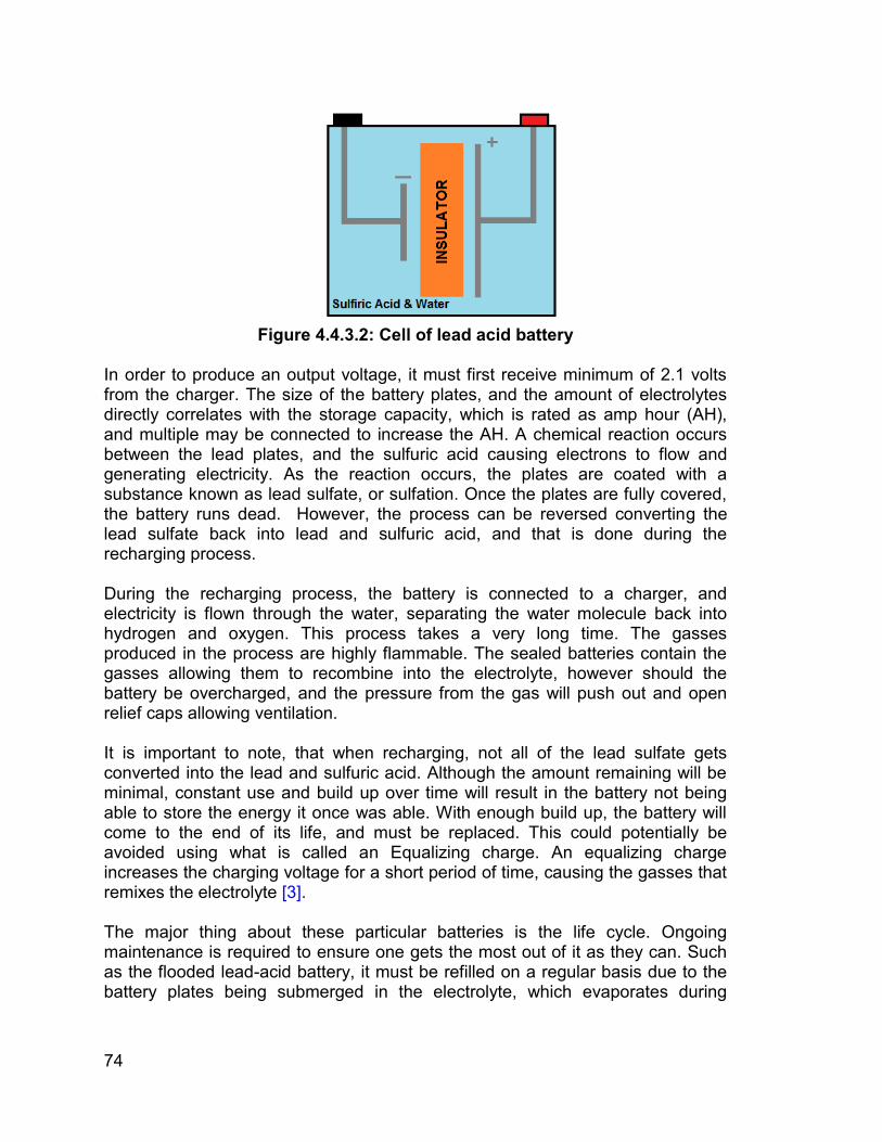
74
Figure 4.4.3.2: Cell of lead acid battery
In order to produce an output voltage, it must first receive minimum of 2.1 volts from the charger. The size of the battery plates, and the amount of electrolytes directly correlates with the storage capacity, which is rated as amp hour (AH), and multiple may be connected to increase the AH. A chemical reaction occurs between the lead plates, and the sulfuric acid causing electrons to flow and generating electricity. As the reaction occurs, the plates are coated with a substance known as lead sulfate, or sulfation. Once the plates are fully covered, the battery runs dead. However, the process can be reversed converting the lead sulfate back into lead and sulfuric acid, and that is done during the recharging process. During the recharging process, the battery is connected to a charger, and electricity is flown through the water, separating the water molecule back into hydrogen and oxygen. This process takes a very long time. The gasses produced in the process are highly flammable. The sealed batteries contain the gasses allowing them to recombine into the electrolyte, however should the battery be overcharged, and the pressure from the gas will push out and open relief caps allowing ventilation. It is important to note, that when recharging, not all of the lead sulfate gets converted into the lead and sulfuric acid. Although the amount remaining will be minimal, constant use and build up over time will result in the battery not being able to store the energy it once was able. With enough build up, the battery will come to the end of its life, and must be replaced. This could potentially be avoided using what is called an Equalizing charge. An equalizing charge increases the charging voltage for a short period of time, causing the gasses that remixes the electrolyte [3]. The major thing about these particular batteries is the life cycle. Ongoing maintenance is required to ensure one gets the most out of it as they can. Such as the flooded lead-acid battery, it must be refilled on a regular basis due to the battery plates being submerged in the electrolyte, which evaporates during
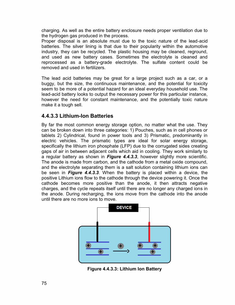
75
charging. As well as the entire battery enclosure needs proper ventilation due to the hydrogen gas produced in the process. Proper disposal is an absolute must due to the toxic nature of the lead-acid batteries. The silver lining is that due to their popularity within the automotive industry, they can be recycled. The plastic housing may be cleaned, reground, and used as new battery cases. Sometimes the electrolyte is cleaned and reprocessed as a battery-grade electrolyte. The sulfate content could be removed and used in fertilizers. The lead acid batteries may be great for a large project such as a car, or a buggy, but the size, the continuous maintenance, and the potential for toxicity seem to be more of a potential hazard for an ideal everyday household use. The lead-acid battery looks to output the necessary power for this particular instance, however the need for constant maintenance, and the potentially toxic nature make it a tough sell. 4.4.3.3 Lithium-Ion Batteries By far the most common energy storage option, no matter what the use. They can be broken down into three categories: 1) Pouches, such as in cell phones or tablets 2) Cylindrical, found in power tools and 3) Prismatic, predominantly in electric vehicles. The prismatic types are ideal for solar energy storage, specifically the lithium iron phosphate (LFP) due to the corrugated sides creating gaps of air in between adjacent cells which aid in cooling. They work similarly to a regular battery as shown in Figure 4.4.3.3, however slightly more scientific. The anode is made from carbon, and the cathode from a metal oxide compound, and the electrolyte separating them is a salt solution containing lithium ions can be seen in Figure 4.4.3.3. When the battery is placed within a device, the positive Lithium ions flow to the cathode through the device powering it. Once the cathode becomes more positive than the anode, it then attracts negative charges, and the cycle repeats itself until there are no longer any charged ions in the anode. During recharging, the ions move from the cathode into the anode until there are no more ions to move.
Figure 4.4.3.3: Lithium Ion Battery
76
According to the U.S. Solar Energy Monitor 70% of the energy storage technology is lithium ion, however the vanadium flow batteries are beginning to make a name for themselves. G.N. Lewis started his work with the lithium battery way back in 1912, but it was not until the 1970s that the first non-rechargeable battery became available. Compared to the nickel-cadmium predecessor, the lithium-ion typically has twice the energy density, and has a higher output voltage [4]. Because lithium is the lightest of all the metals, it has the largest electrochemical potential, and also provides the largest energy density for its weight. Most of today’s cellular devices run on a single celled lithium outputting roughly 3.6 volts, whereas the nickel-based battery pack would need three of the 1.2 volt cells, just to match the output of a single cell lithium [3]. The low maintenance battery with no memory, and no scheduled cycling necessary for maintaining the life cycle. The largest benefit of lithium-ion seems to be the high charge and discharge efficiencies, which will help it harvest more energy, particularly from solar panels. Not to mention, how efficient they are while idle. The durability of lithium-ion proves to be large boost. They are lightweight therefore easy to install and replace if needed, they could be wall mounted and installed both indoors and outdoors, and they are solid, as to not require any kind of refilling or extra maintenance. However, one downside is the time for recharge. The lithium ions tend to take longer to charge than many others. The positive is the amount of research that has gone into them to reduce the time, and increase their efficiency. They do also come at a price, the price tag that is. Depending on who you read up on, the cost could potentially range from $500/kWh to $950/kWh. The majority reasoning for the large price range is the need for a battery management system. The management system would monitor the voltage, and temperature of each cell in order to prevent excessive charging and discharging. Most recently many customers of the Samsung Galaxy Note 7 reported the phone catching fire and exploding. This was due to a small sizing error causing the batteries to overheat. The management system would prevent the overheating and thus eliminating the scare of potential explosions (Discussed in Section 4.4.5.0) The newest product on the market comes from the Electric juggernaut in Tesla. In April of 2016 Elon Musk presented the world with the new Tesla Powerwall battery which takes in and stores energy from solar panels. The idea is to connect the entire house to this 10kWh lithium-ion battery as to disconnect the home from the power grid, and become self-sustaining. Partnering with Solarcity, the solar installation company, Tesla foresees a future of renewable energy, and self-sustaining cars and homes. The one drawback, is the storage capacity, and efficiency. In 2013, the average annual electricity consumption for a U.S. household was nearly 11,000 kWh. That is an average of 909 kWh per month. Meaning even the average consumer uses 30 kWh of electricity a day. Thus needing 3 of the Powerwall batteries to power the home just for a single day [5].
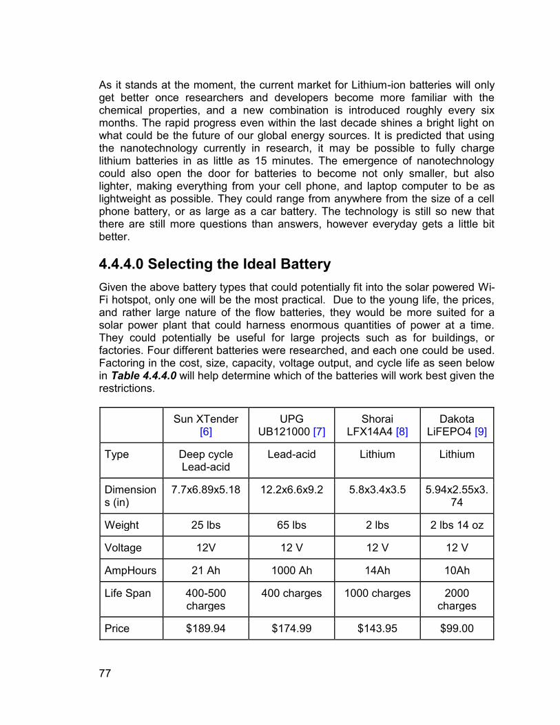
77
As it stands at the moment, the current market for Lithium-ion batteries will only get better once researchers and developers become more familiar with the chemical properties, and a new combination is introduced roughly every six months. The rapid progress even within the last decade shines a bright light on what could be the future of our global energy sources. It is predicted that using the nanotechnology currently in research, it may be possible to fully charge lithium batteries in as little as 15 minutes. The emergence of nanotechnology could also open the door for batteries to become not only smaller, but also lighter, making everything from your cell phone, and laptop computer to be as lightweight as possible. They could range from anywhere from the size of a cell phone battery, or as large as a car battery. The technology is still so new that there are still more questions than answers, however everyday gets a little bit better. 4.4.4.0 Selecting the Ideal Battery
Given the above battery types that could potentially fit into the solar powered Wi-Fi hotspot, only one will be the most practical. Due to the young life, the prices, and rather large nature of the flow batteries, they would be more suited for a solar power plant that could harness enormous quantities of power at a time. They could potentially be useful for large projects such as for buildings, or factories. Four different batteries were researched, and each one could be used. Factoring in the cost, size, capacity, voltage output, and cycle life as seen below in Table 4.4.4.0 will help determine which of the batteries will work best given the restrictions. Sun XTender
[6] UPG
UB121000 [7] Shorai
LFX14A4 [8] Dakota
LiFEPO4 [9]
Type Deep cycle Lead-acid
Lead-acid Lithium Lithium
Dimensions (in)
7.7x6.89x5.18 12.2x6.6x9.2 5.8x3.4x3.5 5.94x2.55x3.74
Weight 25 lbs 65 lbs 2 lbs 2 lbs 14 oz
Voltage 12V 12 V 12 V 12 V
AmpHours 21 Ah 1000 Ah 14Ah 10Ah
Life Span 400-500 charges
400 charges 1000 charges 2000 charges
Price $189.94 $174.99 $143.95 $99.00
78
Table 4.4.4.0: Comparing Different Types of Batteries The chosen battery must provide enough power to run the amplifier, the controller, the inverter, the lights, as well as any devices plugged into the charging station. Ideally the battery would last overnight without charging any devices. Depending on the power demand from the charging station, that will determine how long the battery will last on each charge. According to initial estimates, a 12 volt battery with 6-8 Ampere Hour output should be more than enough to sustain power, however in case it is not, multiple batteries must be connected to increase the total capacity. A general rule of thumb would be to always have more power than necessary, but due to the tight budgetary restraints, minimizing the unnecessary spending will be a large boost. 4.4.5.0 Potential Problems with the Battery
Due to the potentially harmful chemicals found in every kind of battery, the risk of injury is far too great to ignore. It is the responsibility of the designer to ensure there is no risk of using any of the equipment. Of all the equipment built into the Solar Powered Wi-Fi Amplifier, the most dangerous is by far the batteries. Anything from overheating, to overcharging, or incorrect setup could prove to be disastrous. Most recently, and possibly the most well-known, are the reports of the batteries inside the Samsung Galaxy Note 7 catching fire, and some even exploding harming numerous of its users, and example is shown in Figure 4.4.5.0. The issues could be pinpointed to the irregularly sized batteries which caused overheating. The improper sizing lead to a massive recall costing Samsung over $5 billion. The fear of spontaneous combustion spread throughout the public leading to the phones being banned from flights, and set the standard in what could go wrong if not designed correctly. A massive recall was rushed to replace every faulty battery, however the problems did not stop there. The second round of batteries also proved to be faulty. The rushed recall did not solve the problem. The pins inside the oversized batteries were being bent out of shape, causing a short, which lead to the overheating, which ultimately lead to the cancellation of the Note 7. Although Samsung reports that 96% of the faulty phones have been returned, there are still thousands potential weapons out there today. Rumor has it that Apple has also reported the same issue, however the incidents are scattered enough that it does not seem to be a problem with the internal battery, but rather users using faulty third party chargers.
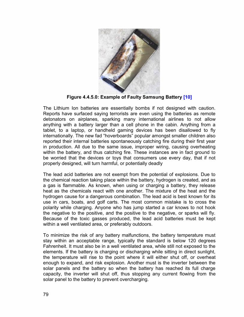
79
Figure 4.4.5.0: Example of Faulty Samsung Battery [10]
The Lithium Ion batteries are essentially bombs if not designed with caution. Reports have surfaced saying terrorists are even using the batteries as remote detonators on airplanes, sparking many international airlines to not allow anything with a battery larger than a cell phone in the cabin. Anything from a tablet, to a laptop, or handheld gaming devices has been disallowed to fly internationally. The new fad “hoverboards” popular amongst smaller children also reported their internal batteries spontaneously catching fire during their first year in production. All due to the same issue, improper wiring, causing overheating within the battery, and thus catching fire. These instances are in fact ground to be worried that the devices or toys that consumers use every day, that if not properly designed, will turn harmful, or potentially deadly The lead acid batteries are not exempt from the potential of explosions. Due to the chemical reaction taking place within the battery, hydrogen is created, and as a gas is flammable. As known, when using or charging a battery, they release heat as the chemicals react with one another. The mixture of the heat and the hydrogen cause for a dangerous combination. The lead acid is best known for its use in cars, boats, and golf carts. The most common mistake is to cross the polarity while charging. Anyone who has jump started a car knows to not hook the negative to the positive, and the positive to the negative, or sparks will fly. Because of the toxic gasses produced, the lead acid batteries must be kept within a well ventilated area, or preferably outdoors. To minimize the risk of any battery malfunctions, the battery temperature must stay within an acceptable range, typically the standard is below 120 degrees Fahrenheit. It must also be in a well ventilated area, while still not exposed to the elements. If the battery is charging or discharging while sitting in direct sunlight, the temperature will rise to the point where it will either shut off, or overheat enough to expand, and risk explosion. Another must is the inverter between the solar panels and the battery so when the battery has reached its full charge capacity, the inverter will shut off, thus stopping any current flowing from the solar panel to the battery to prevent overcharging.
80
4.4.6.0 Charging the Battery With the solar panels working at an efficiency of only 10-20% and outputting DC voltage. On the sunniest of days, the sun can generate roughly 1 kilowatt of power per square meter, which is then transformed to roughly 130 watts per square meter. The 12 volt panel could potentially increase to 40 volts on a perfectly sunny day, and connecting that voltage directly to a device would fry it. The controller will monitor the total voltage from the solar panels going into the battery to ensure the battery will not overcharge, increasing the charge quality, and prevent unwanted discharge from the battery during low, or no light conditions, such as during a storm, or night time.
81
4.5.0.0 Inverters The electronic world is currently dominated by a concept known as alternating currents or how they are commonly known as AC. The way these currents work is that instead of them being constant like their counterpart, known as direct current or DC for short, is that they operate on a time base system by, how the name suggest, alternate varying by time. They typically resemble a sinusoidal waveform and tend to keep that waveform until the current is cut off. The reason why these alternating currents are very dominant is because they run using a three phase system that either diminish the loss of power or prevents the loss in power when transmitting the power from the generating power plant or substations to the outlet at your house or wherever the electrical appliance will be connected. However, not all power sources are derived in AC but instead in DC. As such, there needs to be apparatus of sorts that is capable of converting between the AC and DC and vice versa. This particular apparatus is called the inverter. The inverter in simple terms takes either DC or AC and converts it to the other. However, not everything is as simple as that nor is it a straight DC to AC or AC to DC because there are various different forms of DC and AC. Though DC doesn’t really have many different forms unlike AC who has various different forms with outside of the sinusoid form AC has a current called a square wave. As the name suggest the waveform of this ‘square wave’ is a square that repeats just like a sinusoidal. In fact, square waves and most of the other types of AC waveforms are just a different version of a sinusoidal wave that was modified or the correct term modulated to acquire a different shape compared to the original sine waveform. 4.5.1.0 Why the Need of an Inverter? Despite the project using a battery supply as its main power source the battery is a DC power supply and not an AC power source. Another power generator is the solar panels with the PV controller which so happens to also generate DC power. Now, why can’t everything operate in DC power? And the reason is because of the Wi-Fi amplifier and the Charging Station embedded in the umbrella operate in AC. As such power from the battery and the solar panels will need to be converted to into AC in order for them to be properly used with no problems in the distribution of power throughout the umbrella. 4.5.2.0 Inverter Requirements Rarely is there something that is just one or two versions at most and the inverter is no different. As such, there are numerous inverters ranging from either brand or functionality. Based on Chapter 7 the DC battery that is going to be used is a 12 volt battery which means that the inverters that will be looked at will be 12V inverters or else some complications will happen in either the inverter not working
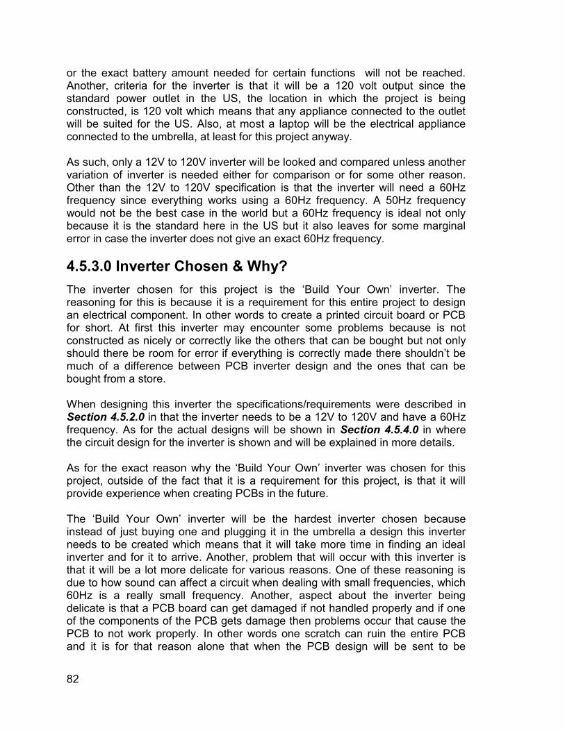
82
or the exact battery amount needed for certain functions will not be reached. Another, criteria for the inverter is that it will be a 120 volt output since the standard power outlet in the US, the location in which the project is being constructed, is 120 volt which means that any appliance connected to the outlet will be suited for the US. Also, at most a laptop will be the electrical appliance connected to the umbrella, at least for this project anyway. As such, only a 12V to 120V inverter will be looked and compared unless another variation of inverter is needed either for comparison or for some other reason. Other than the 12V to 120V specification is that the inverter will need a 60Hz frequency since everything works using a 60Hz frequency. A 50Hz frequency would not be the best case in the world but a 60Hz frequency is ideal not only because it is the standard here in the US but it also leaves for some marginal error in case the inverter does not give an exact 60Hz frequency. 4.5.3.0 Inverter Chosen & Why? The inverter chosen for this project is the ‘Build Your Own’ inverter. The reasoning for this is because it is a requirement for this entire project to design an electrical component. In other words to create a printed circuit board or PCB for short. At first this inverter may encounter some problems because is not constructed as nicely or correctly like the others that can be bought but not only should there be room for error if everything is correctly made there shouldn’t be much of a difference between PCB inverter design and the ones that can be bought from a store. When designing this inverter the specifications/requirements were described in Section 4.5.2.0 in that the inverter needs to be a 12V to 120V and have a 60Hz frequency. As for the actual designs will be shown in Section 4.5.4.0 in where the circuit design for the inverter is shown and will be explained in more details. As for the exact reason why the ‘Build Your Own’ inverter was chosen for this project, outside of the fact that it is a requirement for this project, is that it will provide experience when creating PCBs in the future. The ‘Build Your Own’ inverter will be the hardest inverter chosen because instead of just buying one and plugging it in the umbrella a design this inverter needs to be created which means that it will take more time in finding an ideal inverter and for it to arrive. Another, problem that will occur with this inverter is that it will be a lot more delicate for various reasons. One of these reasoning is due to how sound can affect a circuit when dealing with small frequencies, which 60Hz is a really small frequency. Another, aspect about the inverter being delicate is that a PCB board can get damaged if not handled properly and if one of the components of the PCB gets damage then problems occur that cause the PCB to not work properly. In other words one scratch can ruin the entire PCB and it is for that reason alone that when the PCB design will be sent to be
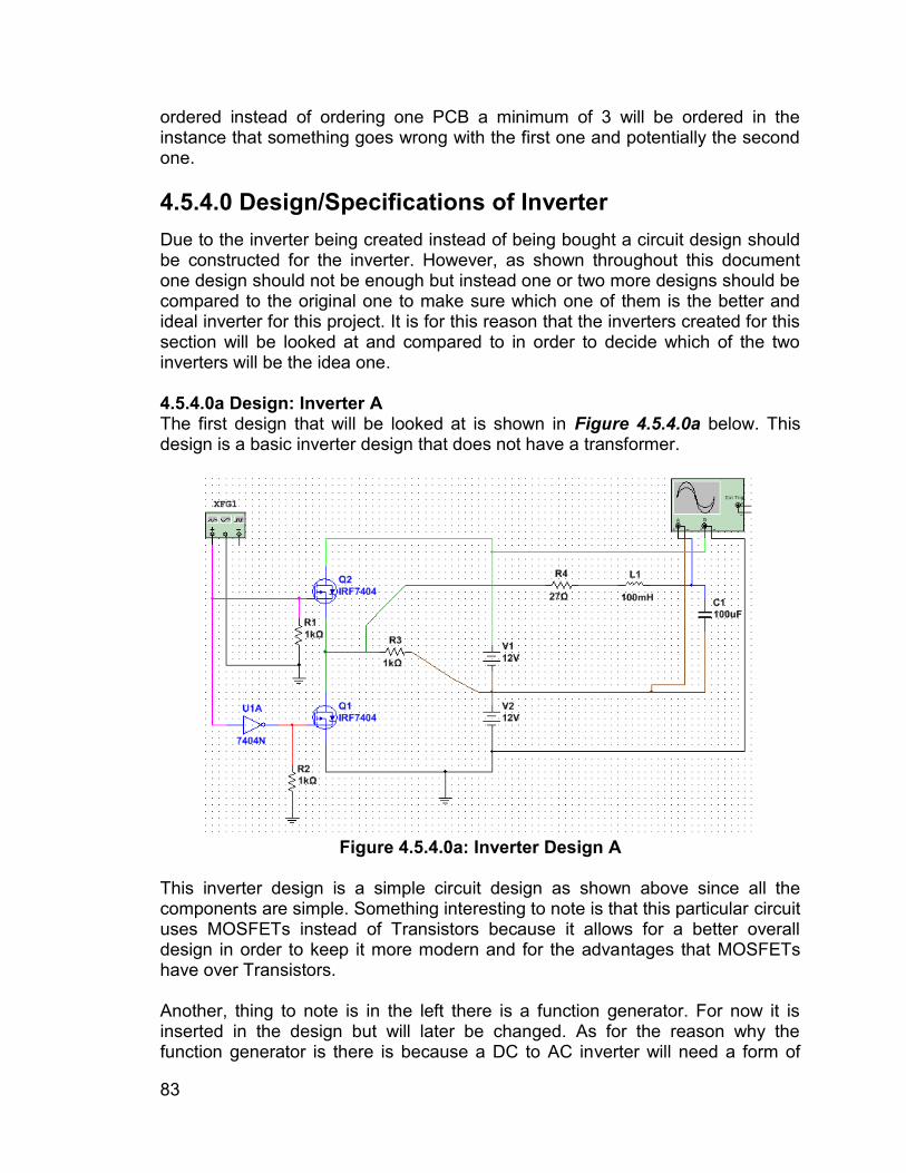
83
ordered instead of ordering one PCB a minimum of 3 will be ordered in the instance that something goes wrong with the first one and potentially the second one. 4.5.4.0 Design/Specifications of Inverter Due to the inverter being created instead of being bought a circuit design should be constructed for the inverter. However, as shown throughout this document one design should not be enough but instead one or two more designs should be compared to the original one to make sure which one of them is the better and ideal inverter for this project. It is for this reason that the inverters created for this section will be looked at and compared to in order to decide which of the two inverters will be the idea one. 4.5.4.0a Design: Inverter A The first design that will be looked at is shown in Figure 4.5.4.0a below. This design is a basic inverter design that does not have a transformer.
Figure 4.5.4.0a: Inverter Design A
This inverter design is a simple circuit design as shown above since all the components are simple. Something interesting to note is that this particular circuit uses MOSFETs instead of Transistors because it allows for a better overall design in order to keep it more modern and for the advantages that MOSFETs have over Transistors. Another, thing to note is in the left there is a function generator. For now it is inserted in the design but will later be changed. As for the reason why the function generator is there is because a DC to AC inverter will need a form of
84
oscillation to give it the sine wave form. What will replace this function generator is an oscillator and what other components will need in order to achieve the same functions that the function generator offer. However, it will not be so simple to implement this transition between the function generator and what other components are needed. 4.5.4.0b Design: Inverter B Unlike the circuit shown in Figure 4.5.4.0a the inverter design in Figure 4.5.4.0b does have a transformer of sorts.
Figure 4.5.4.0b: Inverter Design B
* Disclaimer: the UC3842 is not the actual component that will be used. For now that was the unit that was picked because the actual component that was needed could not be found. However, it can be found or constructed in some other fashion. Unlike the inverter in Figure 4.5.4.0a this inverter is much more complicated due to the inclusion of a transformer and an actual oscillator. The transformer may cause some complications when being implemented in the PCB design. The oscillator may also give some other problems when designing it in the PCB but as stated in the disclaimer an oscillator circuit can be constructed and then implemented in the actual PCB design that will replace the location of the UC3842. 4.5.5.0 Implementation of Inverter on Umbrella The purpose of this particular section is just a brief explanation as to how this inverter will be implemented in the umbrella. As such Section 7.5.0.0 will explain
85
in more details as to how this PCB inverter will be integrated into the umbrella apparatus. The inverter needs to be placed in a safe location that will not receive any harm and can potentially destroy/harm the inverter. For this reason the inverter will be placed in the base of the umbrella structure. The reason for this is because the base of the umbrella will have some sort of protective incasing that will not only protect the inverter but also various other components that will be inside it. 4.5.6.0 Other Possible Inverters As discussed in Section 4.5.2.0 there are various different types of inverters out there and not just the ones that were looked. Another, option is to instead of creating an inverter an inverter can be bought. Yes the learning process would not be ideal but by doing this the margin for error in the project will be minimal (at least for this particular area).
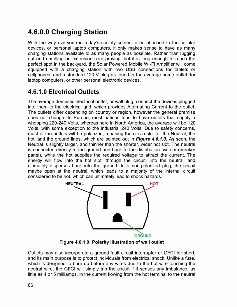
86
4.6.0.0 Charging Station With the way everyone in today’s society seems to be attached to the cellular devices, or personal laptop computers, it only makes sense to have as many charging stations available to as many people as possible. Rather than lugging out and unrolling an extension cord praying that it is long enough to reach the perfect spot in the backyard, the Solar Powered Mobile Wi-Fi Amplifier will come equipped with a charging station with two USB connections for tablets or cellphones, and a standard 120 V plug as found in the average home outlet, for laptop computers, or other personal electronic devices. 4.6.1.0 Electrical Outlets The average domestic electrical outlet, or wall plug, connect the devices plugged into them to the electrical grid, which provides Alternating Current to the outlet. The outlets differ depending on country or region, however the general premise does not change. In Europe, most nations tend to have outlets that supply a whopping 220-240 Volts, whereas here in North America, the average will be 120 Volts, with some exception to the industrial 240 Volts. Due to safety concerns, most of the outlets will be polarized, meaning there is a slot for the Neutral, the hot, and the ground lines, which are pointed out in Figure 4.6.1.0. As seen, the Neutral is slightly larger, and thinner than the shorter, wider hot slot. The neutral is connected directly to the ground and back to the distribution system (breaker panel), while the hot supplies the required voltage to attract the current. The energy will flow into the hot slot, through the circuit, into the neutral, and ultimately disperses back into the ground. In a non-polarized plug, the circuit maybe open at the neutral, which leads to a majority of the internal circuit considered to be hot, which can ultimately lead to shock hazards.
Figure 4.6.1.0: Polarity Illustration of wall outlet
Outlets may also incorporate a ground-fault circuit interrupter or GFCI for short, and its main purpose is to protect individuals from electrical shock. Unlike a fuse, which is designed to burn up before any wires due to the hot wire touching the neutral wire, the GFCI will simply trip the circuit if it senses any imbalance, as little as 4 or 5 milliamps, in the current flowing from the hot terminal to the neutral
87
terminal, and is able to trip in as little as one-thirteenth of a second. For example, picture an individual operating a power tool, and it begins to rain, getting the tool wet. The rain acts as an unintended path for the current to flow through, whether it be the tool, or the operator. Due to the hazardous potential near water, the GFCI receptacle are popular in bathrooms, kitchens, or outdoor areas. The GFCI appears to be identical to a standard outlet, other than two rectangular buttons, one red, and one black, which appear in the middle between the two plugs. The red button is the reset button, which will need to be pressed if the GFCI was tripped, and the problem was fixed. If the problem persists, the outlet will not work until the issue is fixed. The black lower button is the test button, which simply tests if the outlet is working the way it should. It is recommended the GFCIs to be tested at least once a month. A new feature with many receptacles are the new tamper proof outlets. This prevents many small children from sticking unwanted objects into a hot outlet. Inserting any kind of conductive material, such as a paper clip, a fork, knife, or screwdriver will prove to be disastrous. Best case scenario, the outlet melts, and is no longer any use, however worst case scenario could be electric shock, which has been proven to stop the heart, or causing serious burns. The best way to avoid any kind of potential danger is to work with the outlet while the power is turned off, meaning no current is flowing. If no current is flowing, it cannot cause electrocution. Ensuring the correct wires are connected to the correct points on the receptacle is also key. If there is any kind of doubt, there are ground testers available at any hardware store, which will light up and tell just what miswiring is present. The tester would be a cheaper option than a new house after the old one gets burned down due to user error. 4.6.2.0 Universal Serial Bus
Developed in the mid-1990s, the USB is now an industry standard that defines cables for the connection, communication, and power supply between personal devices, and power sources. Every laptop computer, desktop computer, are equipped with multiple USB ports which are used to connect devices such as a keyboard, a mouse, or external storage devices. The industry is so standard at this point, that when purchasing a new electronic device, the only thing that come with it to charge the said device, is the cord. One end is specific to the device itself, but the most popular is the micro USB, which is nearly universal. The other end, or the end that plugs into the computer is equipped with four different pins. Looking at the plug from left to right the furthest on the left is the Ground, the next one is the Data +, followed by the Data -, and finally the +5V Bus. Since it’s unveiling in 1996, the USB has been evolving parallel with the partnered technology. Starting with a maximum transfer rate of 1.5 Mbit/sec, to the latest release in 2013 with a transfer rate of up to 10 Gbit/sec, and the newly designed cables are meant for charging devices. The latest version of power
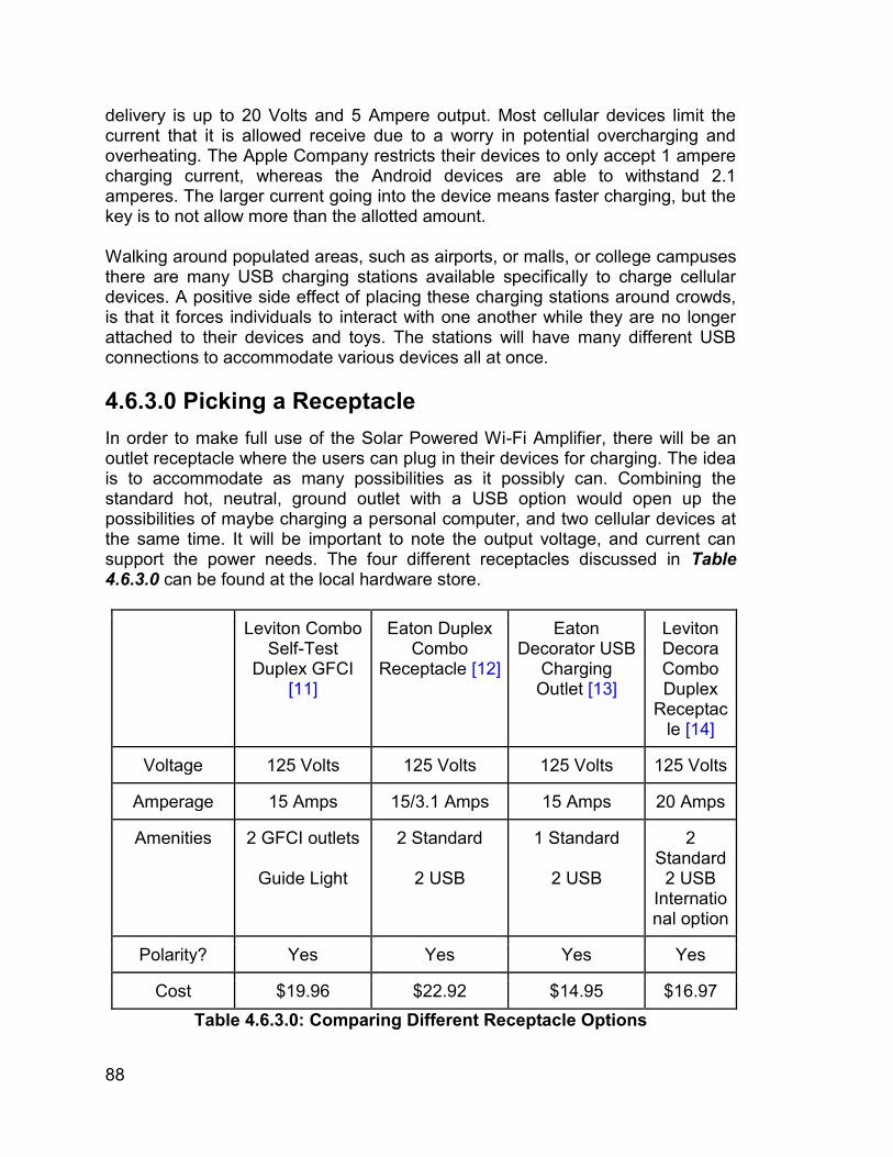
88
delivery is up to 20 Volts and 5 Ampere output. Most cellular devices limit the current that it is allowed receive due to a worry in potential overcharging and overheating. The Apple Company restricts their devices to only accept 1 ampere charging current, whereas the Android devices are able to withstand 2.1 amperes. The larger current going into the device means faster charging, but the key is to not allow more than the allotted amount. Walking around populated areas, such as airports, or malls, or college campuses there are many USB charging stations available specifically to charge cellular devices. A positive side effect of placing these charging stations around crowds, is that it forces individuals to interact with one another while they are no longer attached to their devices and toys. The stations will have many different USB connections to accommodate various devices all at once. 4.6.3.0 Picking a Receptacle
In order to make full use of the Solar Powered Wi-Fi Amplifier, there will be an outlet receptacle where the users can plug in their devices for charging. The idea is to accommodate as many possibilities as it possibly can. Combining the standard hot, neutral, ground outlet with a USB option would open up the possibilities of maybe charging a personal computer, and two cellular devices at the same time. It will be important to note the output voltage, and current can support the power needs. The four different receptacles discussed in Table 4.6.3.0 can be found at the local hardware store.
Leviton Combo Self-Test
Duplex GFCI [11]
Eaton Duplex Combo
Receptacle [12]
Eaton Decorator USB
Charging Outlet [13]
Leviton Decora Combo Duplex
Receptacle [14]
Voltage 125 Volts 125 Volts 125 Volts 125 Volts
Amperage 15 Amps 15/3.1 Amps 15 Amps 20 Amps
Amenities 2 GFCI outlets
Guide Light
2 Standard
2 USB
1 Standard
2 USB
2 Standard
2 USB International option
Polarity? Yes Yes Yes Yes
Cost $19.96 $22.92 $14.95 $16.97 Table 4.6.3.0: Comparing Different Receptacle Options
89
With the high demand of the USB charging options, selecting a receptacle with a USB charging slot is an absolute must. The USB should be a priority over the power outlet due to the popularity of cellphones, and the lower power demand for their charging. If the power distribution demand is less from the charging station, the lights, and the amplifier will be able to operate for a longer time. For simplicity and demonstration sake, the Eaton Decorator USB Charging Outlet will be selected. It allows the flexibility to charge a laptop personal computer, or two separate mobile devices. The amount of power drained from charging must not take away from any of the necessary components. Therefore the charging station will not be a high priority, rather, it will be a just in case option for those who need it. The charging will not be particularly strong, but it should get the job done.
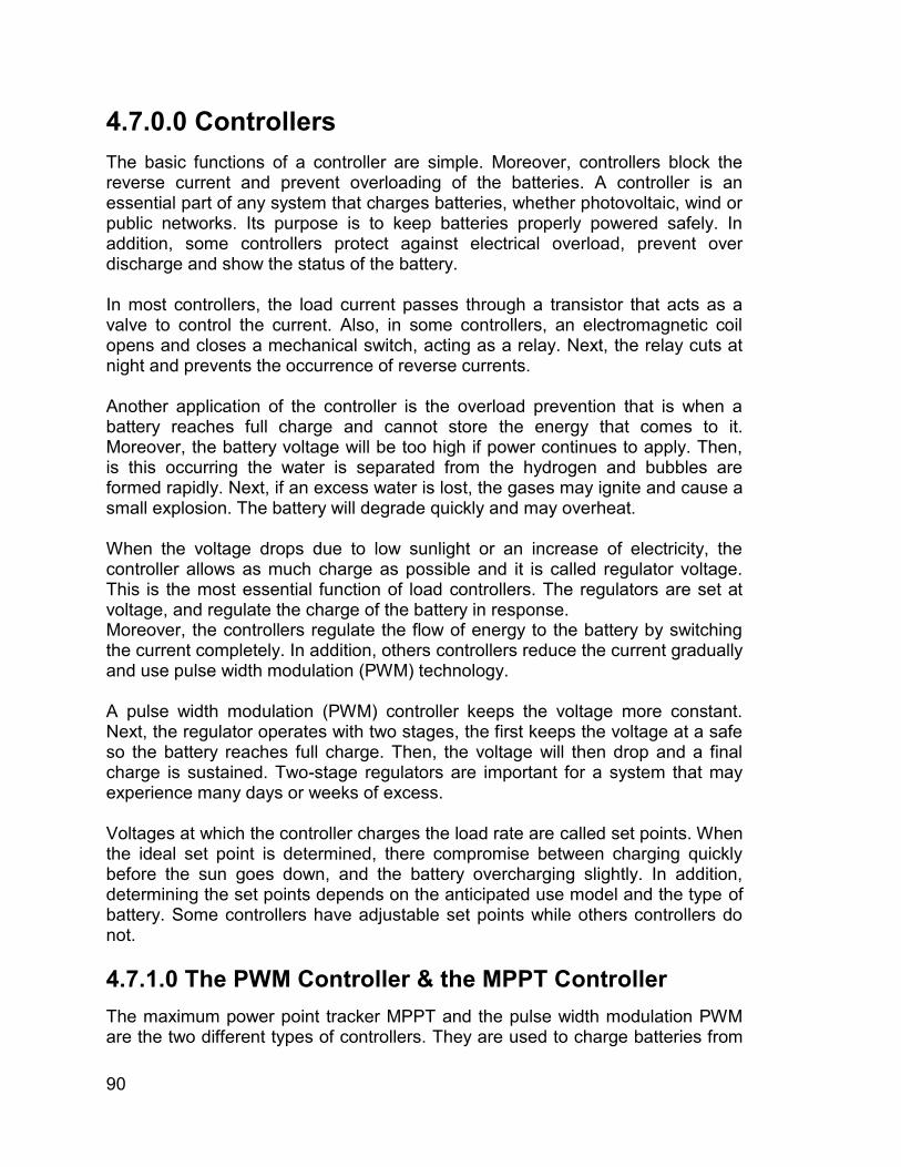
90
4.7.0.0 Controllers The basic functions of a controller are simple. Moreover, controllers block the reverse current and prevent overloading of the batteries. A controller is an essential part of any system that charges batteries, whether photovoltaic, wind or public networks. Its purpose is to keep batteries properly powered safely. In addition, some controllers protect against electrical overload, prevent over discharge and show the status of the battery. In most controllers, the load current passes through a transistor that acts as a valve to control the current. Also, in some controllers, an electromagnetic coil opens and closes a mechanical switch, acting as a relay. Next, the relay cuts at night and prevents the occurrence of reverse currents. Another application of the controller is the overload prevention that is when a battery reaches full charge and cannot store the energy that comes to it. Moreover, the battery voltage will be too high if power continues to apply. Then, is this occurring the water is separated from the hydrogen and bubbles are formed rapidly. Next, if an excess water is lost, the gases may ignite and cause a small explosion. The battery will degrade quickly and may overheat. When the voltage drops due to low sunlight or an increase of electricity, the controller allows as much charge as possible and it is called regulator voltage. This is the most essential function of load controllers. The regulators are set at voltage, and regulate the charge of the battery in response. Moreover, the controllers regulate the flow of energy to the battery by switching the current completely. In addition, others controllers reduce the current gradually and use pulse width modulation (PWM) technology. A pulse width modulation (PWM) controller keeps the voltage more constant. Next, the regulator operates with two stages, the first keeps the voltage at a safe so the battery reaches full charge. Then, the voltage will then drop and a final charge is sustained. Two-stage regulators are important for a system that may experience many days or weeks of excess. Voltages at which the controller charges the load rate are called set points. When the ideal set point is determined, there compromise between charging quickly before the sun goes down, and the battery overcharging slightly. In addition, determining the set points depends on the anticipated use model and the type of battery. Some controllers have adjustable set points while others controllers do not. 4.7.1.0 The PWM Controller & the MPPT Controller The maximum power point tracker MPPT and the pulse width modulation PWM are the two different types of controllers. They are used to charge batteries from
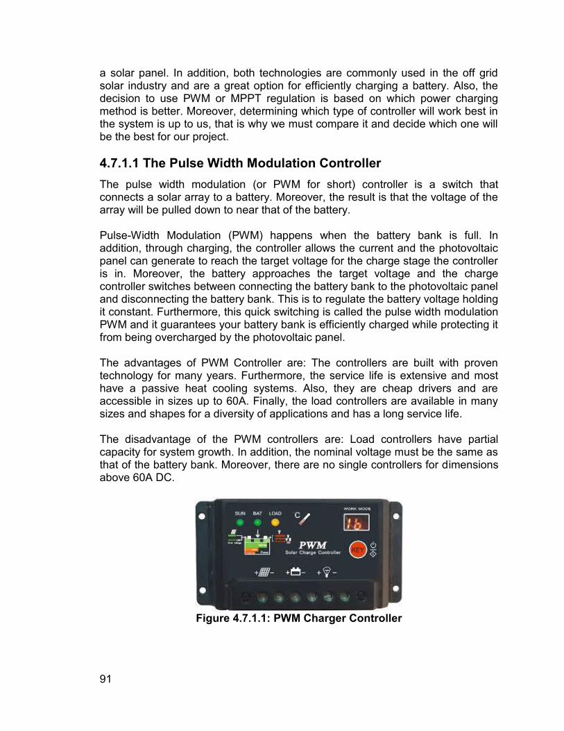
91
a solar panel. In addition, both technologies are commonly used in the off grid solar industry and are a great option for efficiently charging a battery. Also, the decision to use PWM or MPPT regulation is based on which power charging method is better. Moreover, determining which type of controller will work best in the system is up to us, that is why we must compare it and decide which one will be the best for our project. 4.7.1.1 The Pulse Width Modulation Controller The pulse width modulation (or PWM for short) controller is a switch that connects a solar array to a battery. Moreover, the result is that the voltage of the array will be pulled down to near that of the battery. Pulse-Width Modulation (PWM) happens when the battery bank is full. In addition, through charging, the controller allows the current and the photovoltaic panel can generate to reach the target voltage for the charge stage the controller is in. Moreover, the battery approaches the target voltage and the charge controller switches between connecting the battery bank to the photovoltaic panel and disconnecting the battery bank. This is to regulate the battery voltage holding it constant. Furthermore, this quick switching is called the pulse width modulation PWM and it guarantees your battery bank is efficiently charged while protecting it from being overcharged by the photovoltaic panel. The advantages of PWM Controller are: The controllers are built with proven technology for many years. Furthermore, the service life is extensive and most have a passive heat cooling systems. Also, they are cheap drivers and are accessible in sizes up to 60A. Finally, the load controllers are available in many sizes and shapes for a diversity of applications and has a long service life. The disadvantage of the PWM controllers are: Load controllers have partial capacity for system growth. In addition, the nominal voltage must be the same as that of the battery bank. Moreover, there are no single controllers for dimensions above 60A DC.
Figure 4.7.1.1: PWM Charger Controller
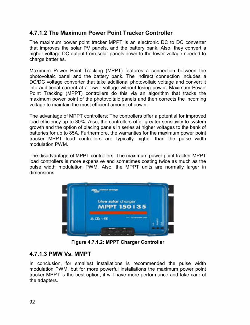
92
4.7.1.2 The Maximum Power Point Tracker Controller The maximum power point tracker MPPT is an electronic DC to DC converter that improves the solar PV panels, and the battery bank. Also, they convert a higher voltage DC output from solar panels down to the lower voltage needed to charge batteries. Maximum Power Point Tracking (MPPT) features a connection between the photovoltaic panel and the battery bank. The indirect connection includes a DC/DC voltage converter that take additional photovoltaic voltage and convert it into additional current at a lower voltage without losing power. Maximum Power Point Tracking (MPPT) controllers do this via an algorithm that tracks the maximum power point of the photovoltaic panels and then corrects the incoming voltage to maintain the most efficient amount of power. The advantage of MPPT controllers: The controllers offer a potential for improved load efficiency up to 30%. Also, the controllers offer greater sensitivity to system growth and the option of placing panels in series at higher voltages to the bank of batteries for up to 85A. Furthermore, the warranties for the maximum power point tracker MPPT load controllers are typically higher than the pulse width modulation PWM. The disadvantage of MPPT controllers: The maximum power point tracker MPPT load controllers is more expensive and sometimes costing twice as much as the pulse width modulation PWM. Also, the MPPT units are normally larger in dimensions.
Figure 4.7.1.2: MPPT Charger Controller
4.7.1.3 PMW Vs. MMPT In conclusion, for smallest installations is recommended the pulse width modulation PWM, but for more powerful installations the maximum power point tracker MPPT is the best option, it will have more performance and take care of the adapters.
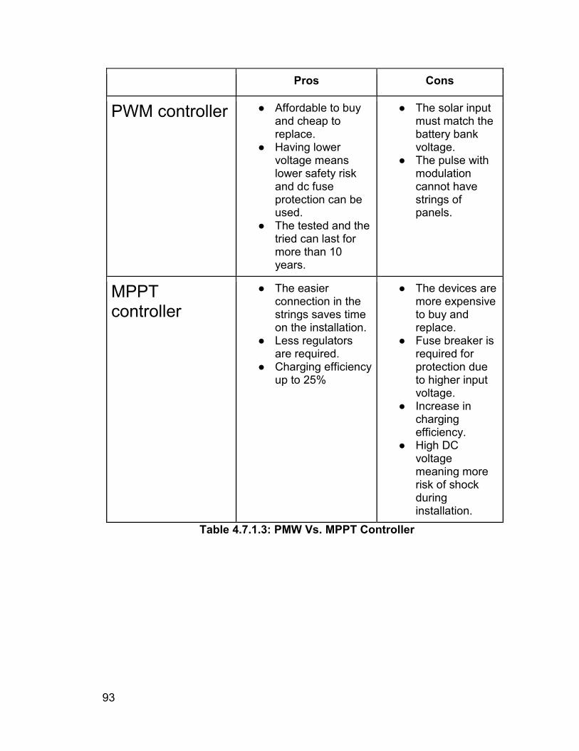
93
Pros Cons
PWM controller ● Affordable to buy and cheap to replace.
● Having lower voltage means lower safety risk and dc fuse protection can be used.
● The tested and the tried can last for more than 10 years.
● The solar input must match the battery bank voltage.
● The pulse with modulation cannot have strings of panels.
MPPT controller
● The easier connection in the strings saves time on the installation.
● Less regulators are required.
● Charging efficiency up to 25%
● The devices are more expensive to buy and replace.
● Fuse breaker is required for protection due to higher input voltage.
● Increase in charging efficiency.
● High DC voltage meaning more risk of shock during installation.
Table 4.7.1.3: PMW Vs. MPPT Controller
94
5.0.0.0 Design Specification In this section we will write about the selections we made in Chapter 4 and how they will be implemented on the umbrella. It will be a small talk in each section. In here would be a great time to post a picture. 5.1.0.0 Housing Apparatus In order to piece everything together, there needs to be something to hold it all together. Any engineer will tell you that when building anything, the most important start is a strong base. Without an able base, anything built up from that would not be able to stand. This is where the real creativity comes in, as our group is full of computer nerds and not real handy with proper tools, or constructing anything outside of a computer. 5.1.0.0a The Base This is the key to ensuring that everything stands the way it is planned. The base must be big enough to hold the batteries, controller, inverter, and stabilizing the stand, but it must not be too large to be cumbersome. It has to be light enough to be mobile, but heavy enough as to prevent the umbrella from being top heavy and toppling over. And due to the multiple electric devices being used, the base must also be well ventilated to allow the heat that will be created to escape and not cause overheating. The first estimates call for a twelve inch by 24 inch base layout, and it might be put together with a few cut to precision 2x4 pieces of wood as the walls, and a sheet of plywood as the flooring. Due to presentation sake, the top will remain open as to show the layout of components and the devices chosen to operate each specific function. Again, this is just the first estimate, and the true dimensions will not be decided until everything is put together and the optimal layout is decided. Every device will be safely mounted to the floor to prevent unwanted movement, and possible damage. 5.1.0.0b The Shaft Sticking up from the base will be the shaft, which will provide the proper height needed for the maximum exposure of the solar panels to the sun. The higher the better, however for show purposes the height will not be too tall as to ease the transportation, and construction on site. The initial plan for the shaft is a PVC piping mainly used for plumbing, but in this case it might do the trick. It should be hard enough to support the top, and thick enough to mount any of the devices chosen inside of it. There is a famous saying
95
that goes “It's not the size that matters, its how you use it” and optimizing the space will show the true genius within this project. 5.1.0.0b The Rib The ribs in an umbrella is the parts that help keep the canopy, sheet/cloth on top that makes it an umbrella and not another stick, which means that the overall integrity of these ribs must be durable because it will have to uphold the weight of the solar panels that will be inserted on top in the canopy section. That is why these particular ribs need to be stronger than your average umbrella and a tad wider than normal because not only will they need to uphold the weight that the canopy and solar panels will give they will also need to hold the lights in place to ensure maximum shining brightness and distances. With the selection of the LED lights, there will not be too much work necessary to ensure optimization. The lights should be bright enough to illuminate the surrounding area with no problems whatsoever. 5.1.0.0c The Canopy A canopy is the sheet or cloth like structure that sits on top of an umbrella. The canopy sometimes can be another material such as metal, aluminum, plastic, and other types of strong materials that usually prevent water from peering in. As for the material in which the canopy will be made for this project varies greatly on the decision to make this umbrella foldable or non-foldable because a foldable umbrella requires a material that is capable of folding without any complications while a non-foldable umbrella requires a more durable material in order to stand more erect without it being destroyed over time and exposure to various outside elements. What will comprise on top of the canopy is the solar panels that will sit upon this canopy, so the canopy must support their weight, as well as allow for perfect solar exposure, while provide appropriate shade coverage to shelter anyone from the harsh rays of the sun. It will be a semi-dome like structure so it can be exposed to the sunlight no matter the suns position in the sky. 5.1.1.0 Base Housing In order to store all of the components together, they will be secured onto a plywood like floor. The components will be left open for display, and demonstration purposes, however in a more practical situation, they would need to be place inside a weather proof casing, while allowing for proper cooling conditions as to not cause overheating. 5.1.1.1 Housing: Battery The battery will be secured down inside the base and positioned as to provide the optimum location to connect each component as necessary. It must be strategically placed as to not cause overheating, or to be overheated due to the nearby components.
96
5.1.1.2 Housing: Inverter The inverter will need to be connected between the battery and the charging station to transform the DC into the usable AC for charging. It will also be inside the base housing, and also strategically located as to not cause overheating, or to be overheated due to nearby components. 5.1.2.0 Shaft Housing Directly in the center of the base, the shaft will need to sit. To ensure the shaft remains upright, the shaft will sit inside a makeshift room using wood as its walls. The walls will prevent the shaft from tipping over as it will fit snuggly without allowing any leeway for shifting. 5.1.2.1 Housing: Charging Station Due to the outdoors narrative, having a hot power outlet exposed to the elements is not ideal. The outlet will have to be placed inside a water proof case and will then be mounted onto the shaft for optimal height to be used by the user. 5.1.2.2 Housing: Wires The ugliest thing that can happen is wires being around especially in the year 2017 that everything is moving more towards a wire-free or wireless environment. As such this project will continue with this trend of being wire-free by finding ways to ‘hide’ the wires in some way. The way they will be hidden is by using the shaft. As stated previously the idea of a PVC pipe is being considered to be a part of the shaft. Not only will the PVC pipe house the charging station it will allow the wires to be hidden from plain site. As to how exactly all of this will be handles will be explained in more details in Chapter 7.0. 5.1.3.0 Rib Housing The ribs as explained previously will most likely be larger/bigger than normal umbrellas. One could say that the ribs will be more related to the ones that a beach umbrella have in order to incorporate the LED lights. 5.1.3.1 Housing: LED Lights As stated previously the LED lights will be implemented in the ribs portion of the umbrella. As to how they will actually be implemented will be explained in more details in Section 7.2 later on. For this section instead of writing how the LED lights will be implemented this section will talk more about the LED lights themselves. Such as the exact LED lights that are being considered to be integrated unlike the entire Section 4.2 in the research portion of the document.
97
5.1.4.0 Canopy Housing Unlike all the other parts of the umbrella that will actually house a portion of the project the canopy will not be housing anything but instead will hold the solar panels in order to get as much sunlight as possible which will not be possible if they are inside the canopy’s shade. 5.1.4.1 Housing: Solar Panels As stated above the solar panels are being placed in the top portion of the canopy in order to receive as much sunlight as possible. As for the way they will be integrated in the canopy varies greatly on whether or not the umbrella is foldable or not because if the umbrella is foldable having a large solar panel will cause various complications when being embedded within the canopy while if the umbrella is non-foldable then having a large solar panel will not cause any issues as long as the solar panel is not a very large size.
98
6.0.0.0 Design Constraints No project has never had any constraints or limitations and this project is not different. In fact this project has the potential of having more limitations than the average project for the simple reasons that this project will not be connected to an ‘unlimited’ power supply but instead rely on solar panels and a battery to provide power. Another, huge limitation about this project is the decision to use Wi-Fi instead of the easier and simpler version the Bluetooth. Not only would this project have limitations as whole each different section/division has their limitations. These limitations for both the divisions and the project as whole is what comprises Chapter 6 and will be discussed, inspected, and a solution will be given to the various potential problems that will occur. 6.1.0.0 Constraints: Solar Panels Arguably, the biggest constraint about the solar panels is how the solar panels will actually be implemented. If the umbrella is foldable the solar panels will need to have accommodate this specification because having large solar panels will result in the umbrella unable to fold or cause the solar panels to not be in the upper portion of the umbrella. As such, this will be a consideration that must be thought out because not just the solar panels rely on the foldable aspect but other components of this project rely on whether or not the umbrella is foldable. If the umbrella is not foldable then all that matter is the size of the umbrella. If the size of the umbrella is small that what would be the point in having a large solar panel. On the other hand having a small solar panel while the umbrella is large would be somewhat of a waste. As such, the design specifications of the umbrella will determine the size of the solar panels that will be integrated in the umbrella. 6.2.0.0 Constraints: LED Lights The biggest constraints that the lights will have is implementing them properly and trying to hide all the wires properly before reaching the shaft where all the wires will be hidden. As such, various different measures need to be taken in order to avoid this mess of wire. The best possible option is to pick an LED light strip(s) that have as little wires as possible while providing a decent illumination to the users. Other than those two constraints that need to be solved when assembling the entire project is to make sure that not only the LED lights stay on in the designated location but they provide enough illumination to the designated areas. The reason for this is because if illumination is limited or very little then the entire
99
portion of the lights is a failure which can result in a grade reduction for the entire project which is something that none of the members in Group 7 want. As such, various precautions will be taken to avoid not only the little illumination issue but also the other two issues mentioned at first. 6.3.0.0 Constraints: Wi-Fi Amplifier The biggest reason for this project was always the Wi-Fi amplifier and it is for this reason that the Wi-Fi amplifier needs to properly perform when being tested and during the presentation to the judges. As for the type of constraints that the Wi-Fi amplifier will encounter is either design problems, wrong coding, or some other issue. The way in which they will be solved is making sure everything is proper before the date in which the project needs to be submitted. Another, thing to note about the Wi-Fi amplifier is that the constraints and errors that may occur are just some of the more basic ones. As time progresses and more is learned about the Wi-Fi amplifier be it from testing or some other changes to the design more constraints and complications will occur and as these complications occur a solution must be made to correct them and make sure everything goes as plan. 6.4.0.0 Constraints: Battery The battery must be powerful enough to send appropriate power to each part, as well as it cannot be too large as to immobilize the entire apparatus. The largest issue could possibly be the amount of time the battery takes to discharge. If the battery runs out of juice, everything else will be unusable. So the battery is a rather important component. 6.5.0.0 Constraints: Inverter Of all the pieces in this project the inverter will be the most sensitive to both complications and constraints for the simple reason that this inverter will be constructed by one of the members of Group 7 instead of the piece being bought. The biggest constraint that the inverter will possess is that it works and does whatever it was design to do. Regarding specific constraints for the inverter is hard to say because not only can the design be changed in Senior Design 2 but various other complications can occur that are only present when the inverter was already ordered and begins actual testing of the piece in either breadboard testing or when connecting other pieces of the project together. If any constraint actually exist is to make sure that everything the inverted was intended to use works properly
100
6.6.0.0 Constraints: Charging Station Due to the large power consumption from the other devices, the charging station will be under a very low restriction on power output. The devices plugged into the station will not charge like they would plugged into an in home outlet. 6.7.0.0 Constraints: Controller Due to the umbrella having a solar panel a controller is needed in order to not just prevent he battery from overcharging but to properly transfer the power obtained from the solar panels into the battery. As such, this controller is very important and needs to be the as best as possible because if something were to go wrong with it the battery of the umbrella could get ruined or worse other components such as the solar panel can get ruined which is bad because these components are some of the more expensive components of the project. 6.8.0.0 Constraints: Housing Apparatus What is a project without a house? And this project is no different. If the housing apparatus is not properly implemented and created many complications will occur and it is for this reason that the housing apparatus will need to be constructed as best as possible in order to design the best possible experiment. As for any specific constraint for the housing apparatus is a hard answer to say simply because there are various constraints and complications that can occur with the construction. All that matters is that the housing apparatus works as it was intended to when the actual construction begins and the various presentations that will occur for this project.
101
7.0.0.0 Design Implementation Chapter 7.0 is comprised of how this entire project will be implemented together. Whether it is just assembling certain pieces together to form a bigger part of the project or assembling the entire thing together to form the umbrella apparatus. What this means is just like any Ikea furniture some assembly is required. The only problem with this project is that unlike the Ikea furniture this project does not come with an instructions manuals which translates to errors will occur while assembling the project. But that is what this chapter is all about. Yes perfection is not possible and constructing this entire project in one go will be damn near impossible but Group 7 are realistic people and understand that errors occur when constructing a project and will take various measures to make sure that as little errors occur while the umbrella apparatus is constructed in order to have the project ready when the demo presentation is needed. Be it for the judges, Dr. Lei Wei, or our very own peers. This entire project has been a divide and conquer and the assembly for this project is no different. As such, each division will make a comeback and in some details will be explained as to how each division will be implemented be it just together or to the housing apparatus of sorts. 7.1.0.0 Implementation: Solar Panels The way in which the solar panels will be implemented onto the umbrella is quite simple. There are two main options for this implementation and they are to either integrate them into the canopy of the umbrella in the instance that the umbrella is foldable and in the instance the umbrella is not foldable the solar panels can be placed on top of the canopy in some form of casing to protect them from various things while also doing the best in hiding the wires in both instances. 7.2.0.0 Implementation: LED Lights As explained in various section throughout this document the LED lights will be implemented in the ribs portion of the umbrella. What makes this particular section different than all the others is that in this section a more in depth explanation of how the LED lights will be implemented onto the ribs will be given. The actual process as to how they will be integrated onto the ribs of the umbrella relies heavily in that the ribs will be much thicker than the standard umbrella otherwise it will not be possible to properly integrate the LED light strip onto the ribs. Assuming the ribs of the umbrella are much thicker than your average umbrella the way the LED lights will be integrated onto them is either because the LED light strip came with a special glue or material that allows them to be ‘glued’ together to the ribs or another substance will be used in order to put the ribs and
102
lights together. As to what these substances could be will also vary on the material in which the ribs are made of. Example, if the ribs are made out of sort of metal a simple glue could not stick the light strip with the metal but instead another gluing substance needs to be used like a special putty, a weld of sorts, or an epoxy that is design for gluing metal together with plastic. The reason why plastic and metal will be glued together is because the LED lights shown in Figure 4.2.3.0 are encased in some sort of plastic substance. However, if the material in which the ribs are made out of is not metal but instead wood then a completely different type of glue will be needed. The glue that will be used for a situation like this is called goop. This glue is one of the best gluing substance if the ribs were made out of wood or wood-like substance. Now, if the ribs of the umbrella were made from some other substance then the glue needed will vary greatly on the substance. One may think that a regular glue or super glue will be enough but as presented throughout this paragraph in order to have the best possible blend a special gluing substance needs to be considered. Other than the special glue needed the actual process to fuse the lights and the material in which the ribs are made out together is not complicated so long as the person doing so uses a good plastic layer to prevent the glue-like substance to touching something other than the ribs and glove just in case some of the glue-like substance touches the person’s hand. The reason for the glove is not because some of these chemicals are toxic or harmful but more so that some of these glues can last a long time before they can be properly removed. 7.3.0.0 Implementation: Wi-Fi Amplifier As explained in Chapter 5 the Wi-Fi amplifier will be inserted inside the base of the umbrella within its own compartment. Other than that there is nothing special about the Wi-Fi amplifier other than the base needs to be properly constructed in order to make sure that all the other components fit properly inside. The biggest issue that would have occurred would have been the wires but due to the amplifier being in the base the answer to that issue is in the base itself. 7.4.0.0 Implementation: Battery The battery will be charged from the solar panels, and then the power will be sent to the charging station, the controller, and the inverter. In order to ensure the power will flow through the circuit, everything must be connected in parallel to avoid any unwanted open circuits. Therefore, if for whatever reason one component fails, it will not stop the others from working. 7.5.0.0 Implementation: Inverter As stated in Section 5.1.1.0 the inverter will be inside the base of the umbrella. As to how it will be implemented inside the base is quite simple. The inverter will be inside a compartment within the base that is connected to the various different
103
components that use the inverter. The components that will require the use of the inverter are Charging Station, Battery, and the Controller (which applies to the solar panels). Other than the special compartment within the base the inverter does not have much problems with implementation. All that matter about the how the inverter gets implemented is that when connected to the devices the inverter works properly. What this means is that when the inverter is in the compartment and connected to the proper devices it functions how the inverter is meant to be used. 7.6.0.0 Implementation: Charging Station The charging station will be connected to the invertor allowing for the correct AC current to be provided. If possible, the amount of output power from the outlet may have to be limited in order to save enough for everything else. 7.7.0.0 Implementation: Controller The controller of the solar panels can be located in one of two places. Either the base or somewhere in the canopy. However, having the controller in the canopy will cause various issues with the main one being space and weight and it is for that reason that the controller will be located in the base alongside various other components. The reason for this is because it allows for better protection from various hazards and will allow for a better control if for some reason it is needed. 7.8.0.0 Implementation: Housing Apparatus Implementing the housing apparatus would be much more complicated than the various other components of this project for the simple reason that if the entirety of the housing apparatus is constructed from scratch there will be many issues and design implementation that will need to be applied while if the umbrella portion of the housing apparatus is already constructed then it will be much easier to properly build the entire project because all that will be needed is to modify the sections that will be used from the already constructed umbrella. However, just because a pre-built umbrella is chosen does not mean that everything will go as smoothly because there are some modifications that will be made that will be very hard to do because none of the members are Mechanical engineers which means that several complications will occur despite the umbrella being pre-built.
104
8.0.0.0 Project Management In College one of the biggest things that get student into problems is time management. They want to enjoy the College life and party while also being good students by getting good grades. There are times in which a particular individual is able to make it work on pure luck, they have an easy major, they are smart enough to retain the information learned in class which allows them to do better in exams, or how the 90+% of the students they try their hardest to manage every aspect of their lives. This includes and is not limited to time, money, jobs, assignments, exams, social life, and extracurricular activities. As such, each division of this project needs to be managed in some way shape or form and that is what Chapter 8.0 is all about. Since, there are many different aspects to this project much like everything else in this document this section will also be divided into each different division that makes up this umbrella apparatus. However there are some basic information that must be said before the start of each division and that is in terms of money management the total budget is less than $1000. For now the division of those $1000 is not evenly spread out simply because there are some areas that are cheaper than others or they can be constructed by all or one of the members of Group 7. 8.1.0.0 Management: Solar Panels A 8.2.0.0 Management: LED Lights A 8.3.0.0 Management: Wi-Fi Amplifier A 8.4.0.0 Management: Battery A 8.5.0.0 Management: Inverter A 8.6.0.0 Management: Charging Station A
105
8.7.0.0 Management: Controller A 8.8.0.0 Management: Housing Apparatus A
106
9.0.0.0 Potential Future This umbrella project has a potential future in a world where everything needs to run on either on Wi-Fi or mobile data. However, this particular umbrella may not be the one that sees use simply because this umbrella is not optimal either because of limited resources and/or money. In fact there are many areas in which this project can be improved on since throughout this project various different parts for one of the concepts was looked at. In other words, this umbrella can be equipped with many different components to be completely optimal. Example, being the Solar Panels in how there are many different types of solar panels some being amazing and would be much better overall when implemented in the project but because of their cost it will be to costly for Group 7 to even implement it to the project but instead can just talk and compare these types of solar panels to the one that was chosen to be embedded in the umbrella. Another, aspect that can be completely modified is the entire base, or how it is referred in the project, housing apparatus of the umbrella. For now the possible design involves a PVC pipe where the cables of the PV controller from the Solar Panel, Wi-Fi Amplifier, the Charging Station, and any other necessary cables can run. The reasoning behind a PVC pipe being used is because they will be great for what they will be used for which is just for some testing here and there and a few demo presentations. However, if this product where to go to the public market it will not garner any attention because of the PVC pipe and not being the most aesthetically pleasing umbrella but if more money where to go into it instead of using a PVC pipe is the shaft of the umbrella another type of pipe could be used in order to make it look more professional and appealing to a consumer's eyes. A monumental difference from this project and future potential ideas/projects based in this is the battery. For right now the battery being used is just enough to do some basic things like charge a phone and a laptop if needed. This may sound good and ok but the problem is the battery being used is not what is called the optimal battery in the sense that it is actually large. Nowadays, batteries for electronics is not just some car battery like substance but instead a lithium-ion battery that is small and thin. If this other type of battery is used the entire housing apparatus of the umbrella including the shaft can be potentially change completely because instead of having to carry around a decent size battery in the housing apparatus a smaller size battery is applied. Which if mounted in properly can be either mounted in either the base, shaft, or upper portion of the umbrella. As can be seen this project has many different possibilities that as of right now cannot be achieved because of the reasons of money or limited resources

107
available however this project has lots of potential for future uses especially if someone or a company that has money and resources.
108
10.0.0.0 Epilogue As seen throughout this document there are many steps and comparisons that need to be accounted for before the construction of any project and this umbrella project is no exception. Especially a project that has to deal with various different areas embedded inside an apparatus in order to not let wires and other electrical components show and make it look unprofessional. As such, the project was divided into different portions and split between the members of Group 7 to research, compare, and construct instead of having each member doing the same thing and potentially not reach the fullest potential. In Chapter 3 the project was broken down into 8 portions which are Solar Panels, Lighting/Illumination, Wi-Fi Amplifier, Battery, Inverter, Charging Station, Controller, and Housing Apparatus. In the beginning of the idea process only three of the eight sections (Solar Panels, Wi-Fi Amplifier, Battery) were being included in the final project but as time progressed and more research was put into the project a conclusion was made that these three section could not only garner enough attention from potential buyers but also support the project alone. As such each of the different section of this umbrella are crucial for a successful execution (including the lights). Even if one particular area may not seem that important in the end each component that is a part of this project has a purpose of sorts that will be displayed in the final construct of this umbrella. On another note, the current status of the project has yet found each ideal finalized component that will be a part of it which means that everything so far is just a comparison of various aspects that can potentially go inside this project. However, as time progresses and more research and time is put into this project a proper conclusion will be reached in not just the parts that will be used but also results and analysis that must happen before the possibility of creating this umbrella apparatus.
109
Appendix A References **Leaving until the end to ensure smooth transitions and continuity 5.0
1. http://www.historyoflighting.net/lighting-history/history-of-torches/ 2. http://www.historyoflighting.net/lighting-history/history-of-candles/ 3. http://zenstoves.net/Sterno.htm 4. http://www.bulbs.com/learning/incandescent.aspx 5. http://www.childcarequarterly.com/pdf/fall11_lighting.pdf 6. http://www.bulbs.com/learning/halogen.aspx 7. http://www.explainthatstuff.com/howneonlampswork.html 8. http://www.livescience.com/33895-human-eye.html 9. https://www.energystar.gov/products/lighting_fans/light_bulbs/learn_about_led_b
ulbs 10. http://hub.currentbyge.com/current-articles/cfl-vs-halogen-vs-led
6.0
1. https://www.statista.com/statistics/218596/global-number-of-public-hotspots-since-2009/
2. http://www.pcmag.com/article2/0,2817,2427010,00.asp 3. http://www.pcmag.com/encyclopedia/term/57165/cellular-vs-wi-fi 4. http://www.toptenreviews.com/services/articles/satellite-internet-101-how-does-it-
work/ 5. https://www.repeaterstore.com/pages/wifi-booster-repeater-extender-differences 6. http://www.digitaltrends.com/mobile/4g-vs-lte/2/ 7. http://www.reviews.org/internet-service/best-satellite-internet-providers/ 8. http://www.androidcentral.com/what-are-coverage-maps-us-carriers 9. http://energyusecalculator.com/electricity_wifirouter.htm 10. https://www.verizonwireless.com/internet-devices/verizon-jetpack-4g-lte-mobile-
hotspot-ac791l/ 11. http://offgridsurvival.com/offgridinternet/ 12. http://www.tomsguide.com/us/best-wifi-extenders,review-2225.html 13. https://www.lifewire.com/best-wifi-extenders-4043312 14. http://www.toprateten.com/best-wifi-extender/ 15. http://www.pcmag.com/article2/0,2817,2478817,00.asp 16. http://thewirecutter.com/reviews/best-mobile-wi-fi-hotspot/ 17. https://www.cnet.com/topics/networking/best-networking-devices/hot-spot/ 18. https://www.verizonwireless.com/internet-devices/verizon-jetpack-4g-lte-mobile-
hotspot-ac791l/ 19. https://www.att.com/devices/netgear/unite-pro-refurb.html#sku=undefined 20. https://www.wired.com/2014/05/mifi-liberate/
110
21. https://9to5mac.com/2017/02/19/the-new-wave-of-unlimited-data-plans-how-verizon-sprint-t-mobile-and-att-compare/
22. https://www.cnet.com/news/4g-lte-showdown-how-fast-is-your-carrier/ 23. http://www.reviews.org/internet-service/best-satellite-internet-providers/ 24. Labeled as [source]
http://www.downloads.netgear.com/files/GDC/EX7000/EX7000_QSG_EN.pdf
25. 7.0 [1] “What is the best type of battery for solar storage?” http://www.solarpowerworldonline.com/2015/08/what-is-the-best-type-of-battery-for-solar-storage/ [2] “Lower-cost Flow Batteries to create $190 Million Energy Storage Market in 2020” http://www.luxresearchinc.com/news-and-events/press-releases/read/lower-cost-flow-batteries-create-190-million-energy-storage [3] “How lead acid batteries work” http://www.progressivedyn.com/battery_basics.html [4] “Is Lithium-ion the ideal battery?” http://batteryuniversity.com/learn/archive/is_lithium_ion_the_ideal_battery [5] “Tesla’s new $3,500 10 kWh Powerwall home battery lets you ditch the grid http://inhabitat.com/teslas-powerwall-battery-is-a-stylish-but-expensive-way-to-ditch-the-grid/ [6] Sun x tender http://www.sunxtender.com/solarbattery.php?id=1 [7] UPG UB121000 http://www.atbatt.com/upg-ub121000-12v-100ah-sealed-lead-acid-battery.asp?gclid=Cj0KEQjwk-jGBRCbxoPLld_bp-IBEiQAgJaftaI4gXf5GN4CKqWbUoORRyuf8sQ_RfMTvVXgzrvKYxAaAtf38P8HAQ [8] Shorai LFX14A4 https://www.amazon.com/Shorai-423806-LFX14A4-BS12-Lithium-Battery/dp/B007GR5DC0 [9] Dakota LiFEPO4 http://www.electric-bike-kit.com/12v-lithium-lifepo4-replacement.aspx?gclid=Cj0KEQjwk-jGBRCbxoPLld_bp-IBEiQAgJaftb9FGvqiKrA9YlKx8OWbCs4Yiva3gIz6kQ6BHNtvpiEaApes8P8HAQ
111
[10] “Here’s why the Samsung Galaxy Note 7 batteries caught fire and exploded” http://www.techradar.com/news/samsung-galaxy-note-7-battery-fires-heres-why-they-exploded 8.0 [11] Leviton Combo Self-Test Duplex GFCI http://www.homedepot.com/p/Leviton-15-Amp-125-Volt-Combo-Self-Test-Duplex-Guide-Light-and-Tamper-Resistant-GFCI-Outlet-White-R92-GFNL1-00W/206000175 [12] Eaton Duplex Combo Receptacle http://www.homedepot.com/p/Eaton-15-Amp-125-Volt-Combination-Outlet-and-2-USB-3-1-Amp-Charger-with-Duplex-Receptacle-White-TR7755W-BOX/206436676 [13] Eaton Decorator USB Charging Outlet http://www.homedepot.com/p/Eaton-15-Amp-Decorator-USB-Charging-Electrical-Outlet-White-TR7740W-K/203492681 [14] Leviton Decora Combo Duplex Receptacle http://www.homedepot.com/p/Leviton-Decora-20-Amp-125-Volt-Combination-Duplex-Receptacle-and-USB-Charger-White-R02-T5832-0BW/205554681