Embed Size (px)
Citation preview

UltraGRIND CONTROL PANELSINSTALLATION & OPERATION MANUAL
Form No. 099813-Rev. D
IMPORTANT: Read all instructions in this manual before operating. As a result of Crane Pumps & Systems Inc.constant product improvement program, product changes may occur. As such Crane Pumps & Systems, Inc., reserves the right to change product without prior written notification.
Series: 100 - SimplexUGP, UGP-P, UCP & UCP-P
Series: 200 - DuplexUGP & UCP
420 Third Street/P.O. Box 603 83 West Drive, BramptonPiqua, Ohio 45356-0603 Ontario, Canada L6T 2J6Phone: (937) 778-8947 Phone: (905) 457-6223Fax: (937) 773-7157 Fax: (905) 457-2650www.cranepumps.com
PUMPS & SYSTEMS
A Crane Co. Company

TABLE OF CONTENTS
USERS GUIDE .....................................................................................................................3
WARNINGS AND SAFETY PRECAUTIONS........................................................................4
SPECIFICATIONS ................................................................................................................5 - 6
A. GENERAL INFORMATIONReceiving, Storage, Service Centers, Location.....................................................................7
B. PRODUCT REVIEWGeneral Component Description)..........................................................................................7 - 8Principles of Operation - Simplex..........................................................................................8Principles of Operation - Duplex ...........................................................................................8
C. INSTALLATION OF WALL MOUNT PANELS.......................................................................11INSTALLATION OF PANELS IN BASIN COVER .................................................................11 - 12
D. REPLACEMENT PARTS ......................................................................................................12
TYPICAL UGP SIMPLEX WALL MOUNT SCHEMATIC ......................................................13TYPICAL UGP-P SIMPLEX COVER MOUNT SCHEMATIC ...............................................14TYPICAL UGP DUPLEX WALL MOUNT SCHEMATIC ........................................................15TYPICAL UGP COMPONENT DRAWING /PARTS LIST .....................................................16
TYPICAL UCP SIMPLEX WALL MOUNT SCHEMATIC ......................................................17TYPICAL UCP-P SIMPLEX COVER MOUNT SCHEMATIC ...............................................18TYPICAL UCP COMPONENT DRAWING /PARTS LIST .....................................................19
ELECTRICAL DATA .............................................................................................................20
RETURNED GOODS POLICY..............................................................................................21WARRANTYREGISTRATION
Other brand and product names are trademarks or registered trademarks of their respective holders.UltraGRIND is a trademark of Barnes Pumps, Inc.® Barnes is a registered trademark of Barnes Pumps, Inc.© Barnes Pumps, Inc. 1997, 2000, 2003 Alteration Rights Reserved. Printed in U.S.A.
2
USER GUIDECongratulations onyour purchase of aBarnes UltraGRIND grinder pump system.With proper care and by following a fewsimple guidelines your grinder pump will giveyou many years of dependable service.
Use and CareThe UltraGRIND grinder pump station isdesigned to handle routine, domesticsewage. Solid waste materials should bethrown in the trash. While your station iscapable of accepting and pumping a widerange of materials, regulatory agenciesadvise that the following items should not beintroduced into any sewer either directly orthrough a kitchen waste disposal:
• Glass• Metal• Diapers• Socks, rags or cloth• Plastic objects (e.g., toys, utensils, etc.)• Sanitary napkins or tampons
In addition you must NEVER introduce intoany sewer:
• Explosives• Flammable Material• Lubricating Oil and/or Grease• Strong Chemicals• Gasoline
General InformationYour home wastewater disposal service ispart of a low pressure sewer system. The keyelement in this system is the BarnesUltraGRIND grinder pump station. The basincollects all wastewater from the house. Thesolids in the sewage are then ground to asmall size suitable for pumping in the slurry.
The grinder pump generates sufficient pressure to pump this slurry from your home to the wastewaterplant.
Power FailureYour grinder pump cannot dispose ofwastewater or provide an alarm signal withoutelectrical power. If electrical power service isinterrupted, keep water usage to a minimum.
WarrantyYour grinder pump is furnished with awarranty against defects in material orworkmanship. A properly completed StartUp/Warranty Registration form must be on fileat the Barnes factory in order to activate yourwarranty. In addition your pump must beinstalled in accordance with the installationinstructions.If you have a claim under the provisions of thewarranty, contact your local Barnes Pumps,Inc. Distributor.When contacting your representative forservice, please include your station serialnumber, pump model number, and pumpserial number.
For future reference, record the followinginformation:Station Serial No:
Pump Model No:
Pump Serial No:
Local Distributor:
Distributor Telephone:
3

SAFETY FIRST!PLEASE READ THIS BEFORE INSTALLING
OR OPERATING PUMP.GENERAL
1. Most accidents can be avoided by using COMMON SENSE.2. Read this operation and maintenance instruction manual.3. Do not wear loose clothing that may become entangled in the impeller or other moving parts.4. Always wear appropriate safety gear, such as safety glasses, when working on the pump or piping.5. Bronze/brass and bronze/brass fitted pumps may contain lead levels higher than considered safe for potable water systems.
Various government agencies have determined that leaded copper alloys should not be used in potable water applications. For non-leaded copper alloy materials of construction, please contact factory.
6. Minimize the amount of cooking grease entering the system.7. Do Not leave pump cover off the basin, except while servicing, to prevent entrance of foreign materials such as rocks, metal,
soil, animals or humans.8. Prevent large articles of clothing, large amounts of chemicals, other materials or substances such as are uncommon in
domestic sewage from entering the system.9. During power black-outs, discontinue water consumption at the home(s) to prevent sewage from backing up into the house.10. Prevent infiltration or direct flow of rain or run-off water into the pump basin to minimize pump cycling. This will prevent
overloading the treatment facility, and will facilitate swift transportation of sewage.11. Always keep the shut-off valve completely open when system is in operation (unless advised otherwise by the proper authorities).12. Keep the control panel locked or confined to prevent unauthorized access to it.13. If the pump is idle for long periods of time, it is advisable to start the pump occasionally by adding water to the basin.14. Before removing the pump from the basin, be sure to close the shut-off valve. (This prevents backflow from the pressure sewer.)15. Make sure level controls are provided at time of installation.
PUMPS16. Recommended no more than 10 starts per hour.17. Pumps build up heat and pressure during operation-allow time for pumps to cool before handling or servicing.18. Only qualified personnel should install, operate and repair pump.19. Keep clear of suction and discharge openings. DO NOT insert fingers in pump with power connected.20. Do not pump hazardous materials (flammable, caustic, etc.) unless the pump is specifically designed and designated to handle
them.21. Do not block or restrict discharge hose, as discharge hose may whip under pressure.22. Make sure lifting handles are securely fastened each time before lifting.23. Do not lift pump by the power cord.24. Do not exceed manufacturers recommendation for maximum performance, as this could cause the motor to overheat.25. Secure the pump in its operating position so it can not tip over, fall or slide.26. Keep hands and feet away from impeller when power is connected.27. Submersible Pumps are not approved for use in swimming pools, recreational water installations, decorative fountains or any
installation where human contact with the pumped fluid is common.28. Do not operate pump without safety devices in place.29. Always replace safety devices that have been removed during service or repair.
ELECTRICAL30. To reduce risk of electrical shock, pump must be properly grounded in accordance with the National Electric Code (NEC) and all
applicable state and local codes and ordinances.31. To reduce risk of electrical shock, always disconnect the pump from the power source before handling or servicing. Lock out
power and tag.32. Any wiring of pumps should be performed by a qualified electrician.33. Never operate a pump with a power cord that has frayed or brittle insulation.34. Cable should be protected at all times to avoid punctures, cut, bruises and abrasions - inspect frequently.35. Never handle connected power cords with wet hands.36. Do not remove cord and strain relief. Do not connect conduit to pump.37. To reduce risk of electrical shock, all wiring and junction connections should be made per the NEC and applicable state
and local codes. Requirements may vary depending on usage and location. See wiring diagrams in manual.38. Do Not operate the pump in the "HAND" control position and leave the pump unattended.
IMPORTANT! BARNES® PUMPS, INC. IS NOT RESPONSIBLE FOR LOSSES, INJURY, OR DEATH RESULTING FROM AFAILURE TO OBSERVE THESE SAFETY PRECAUTIONS, MISUSE OR ABUSE OF PUMPS OR EQUIPMENT.
4

Standard Features:• NEMA 4X Fiberglass enclosure.• Pump circuit breaker.• UGP - IEC rated motor star ter with ambient
compensated overload relay. UCP - Pumps havemotor overload intragal in pump motor windings.
• Motor Start pushbutton.• Separate circuit fuses for Control and Alarm circuits.• 25 watt high level alarm light.• UGP - Pre-installed start capacitor kit.
UCP - SGPC pumps have capacitor internal to pump.• Terminal strip and ground lug for all incoming
connections.
Optional Features:• 90 db alarm horn with 10 amp Silence control relay
and NEMA 4X Silence pushbutton.• 7 digit elapsed time meter with meter running indicator.• 30 amp Automatic Transfer Switch with easy access
30 amp reverse pin portable generator receptacle andweatherproof cover.
• Seal Leak Indication with 120 volt indicator lamp andterminals for 2 leak probe wires (UGP Only).
UGP Panels used with SGV Grinder Pumps.UCP Panels used with SGPC Grinder Pumps.
UGPSIMPLEX
UGPDUPLEX
UCPSIMPLEX
UCPDUPLEX
DESCRIPTION
UGP-101 UGP-201 UCP-101 UCP-201 NEMA 4X Fiberglass Enclosure, Operating Controls, Alarm Light.
UGP-102 UGP-202 UCP-102 UCP-202 NEMA 4X Fiberglass Enclosure, Operating Controls, Audio Alarmw/Push Button Silence & Alarm Light.
UGP-103 UGP-203 N/A N/A NEMA 4X Fiberglass Enclosure, Operating Controls, Seal LeakDetection, & Alarm Light.
UGP-104 UGP-204 N/A N/A NEMA 4X Fiberglass Enclosure, Operating Controls, Seal LeakDetection, Audio Alarm w/Push Button Silence & Alarm Light.
UGP-105 UGP-205 UCP-105 UCP-205 NEMA 4X Fiberglass Enclosure, Operating Controls, GeneratorReceptacle & Alarm Light.
UGP-106 UGP-206 UCP-106 UCP-206 NEMA 4X Fiberglass Enclosure, Operating Controls, GeneratorReceptacle, Audio Alarm w/Push Button Silence & Alarm Light.
UGP-107 UGP-207 N/A N/A NEMA 4X Fiberglass Enclosure, Operating Controls, Seal LeakDetection, Generator Receptacle & Alarm Light.
UGP-108 UGP-208 N/A N/A NEMA 4X Fiberglass Enclosure, Operating Controls, Seal LeakDetection, Generator Receptacle, Audio Alarm w/Push Button Silence& Alarm Light.
UGP-109 UGP-209 UCP-109 UCP-209 NEMA 4X Fiberglass Enclosure, Operating Controls, Alarm Light &Elapsed Time Meter.
UGP-110 UGP-210 UCP-110 UCP-210 NEMA 4X Fiberglass Enclosure, Operating Controls, Audio Alarmw/Push Button Silence, Alarm Light & Elapsed Time Meter.
UGP-111 UGP-211 N/A N/A NEMA 4X Fiberglass Enclosure, Operating Controls, Seal LeakDetection, Alarm Light & Elapsed Time Meter.
UGP-112 UGP-212 N/A N/A NEMA 4X Fiberglass Enclosure, Operating Controls, Seal LeakDetection, Audio Alarm w/Push Button Silence, Alarm Light & ElapsedTime Meter.
UGP-113 UGP-213 UCP-113 UCP-213 NEMA 4X Fiberglass Enclosure, Operating Controls, GeneratorReceptacle, Alarm Light & Elapsed Time Meter.
UGP-114 UGP-214 UCP-114 UCP-214 NEMA 4X Fiberglass Enclosure, Operating Controls, GeneratorReceptacle, Audio Alarm w/Push Button Silence, Alarm Light, &Elapsed Time Meter.
UGP-115 UGP-215 N/A N/A NEMA 4X Fiberglass Enclosure, Operating Controls, Seal LeakDetection, Generator Receptacle, Alarm Light & Elapsed Time Meter.
UGP-116 UGP-216 N/A N/A NEMA 4X Fiberglass Enclosure, Operating Controls, Seal LeakDetection, Generator Receptacle, Audio Alarm w/Push Button Silence,Alarm Light & Elapsed Time Meter.
IMPORTANT: Control panel sizes and options will vary depending on contract specifications.
Standard UGP & UCP UltraGRIND Control Panels
5

Standard Features:• NEMA 4X Fiberglass enclosure.• Pump circuit breaker.• UGP - IEC rated motor s tarter with ambient
compensated overload relay. UCP - Pumps havemotor overload intragal in pump motor windings.
• Motor Start pushbutton.• Separate circuit fuses for Control and Alarm circuits.• 25 watt high level alarm light.• UGP - Pre-installed start capacitor kit.
UCP - SGPC pumps have capacitor internal to pump.• Terminal strip and ground lug for
all incoming connections.
Optional Features:• 90 db alarm horn with 10 amp Silence control relay
and NEMA 4X Silence pushbutton.• 7 digit elapsed time meter with meter running indicator.• 30 amp Automatic Transfer Switch with easy access
30 amp reverse pin portable generator receptacle andweatherproof cover.
• Seal Leak Indication with 120 volt indicator lamp andterminals for 2 leak probe wires.
UGP Panels used with SGV Grinder Pumps.UCP Panels used with SGPC Grinder Pumps.-P panels used with CONVERTIBLE Cover.
UGP-PSIMPLEX
UCP-PSIMPLEX
DESCRIPTION
UGP-101/2-P UCP-101/2-P NEMA 4X Fiberglass Enclosure, Operating Controls & Remote Alarm Light.
UGP-101/2-P UCP-101/2-P NEMA 4X Fiberglass Enclosure, Operating Controls, with Remote Audio Alarmw/Push Button Silence & Alarm Light.
UGP-103/4-P N/A NEMA 4X Fiberglass Enclosure, Operating Controls, Seal Leak Detection, & AlarmLight.
UGP-103/4-P N/A NEMA 4X Fiberglass Enclosure, Operating Controls, Seal Leak Detection, RemoteAudio Alarm w/Push Button Silence & Alarm Light.
UGP-109/10-P UCP-109/10-P NEMA 4X Fiberglass Enclosure, Operating Controls, Elapsed Time Meter, RemoteAlarm Light.
UGP-109/10-P UCP-109/10-P NEMA 4X Fiberglass Enclosure, Operating Controls, Elapsed Time Meter, RemoteAudio Alarm w/Push Button Silence & Alarm Light.
UGP-111/12-P N/A NEMA 4X Fiberglass Enclosure, Operating Controls, Seal Leak Detection, ElapsedTime Meter, Remote Alarm Light.
UGP-111/12-P N/A NEMA 4X Fiberglass Enclosure, Operating Controls, Seal Leak Detection, ElapsedTime Meter, Remote Audio Alarm w/Push Button Silence & Alarm Light.
IMPORTANT: Control panel sizes and options will vary depending on contract specifications.
Standard UGP-P & UCP-P UltraGRIND Control Panels
MOUNTING:
* = WALL MOUNT (STD).P = POLY INSERT MOUNT
* Left Blank
VOLTAGE:0 = 200 VOLT, 1 PHASE, 60HZ1 = 115 VOLT, 1 PHASE, 60HZ2 = 230 VOLT, 1 PHASE, 60HZ3 = 230 VOLT, 3 PHASE, 60HZ4 = 460 VOLT, 3 PHASE, 60HZ5 = 575 VOLT, 3 PHASE, 60HZ6 = 200 VOLT, 3 PHASE, 60HZ
UCP -101 -2 1 -P
PUMP SERIES:UGP =UltraGRIND
UCP =UltraCAV
HORSEPOWER:1 = 1HP2 = 2HP3 = 3HP5 = 5HP
7.5 = 7.5HP
PANEL MODEL:101 thru 116, Simplex201 thru 216, Duplex
6

SECTION A: GENERAL INFORMATION
A-1) RECEIVING:Upon receiving the Control Panel, it should be inspected fordamage or shortages. If damage has occurred, file a claimimmediately with the company that delivered the basinpackage.
A-2) STORAGE:For best results, control panels should be stored in atemperature controlled area that provides protection from theelements and humidity.
A-3) SERVICE CENTERS:For the location of the nearest Barnes® Pumps Service Center,check your catalog, your Barnes Pumps, Inc. representative orBarnes Pumps, Inc. Service Department in Piqua, Ohio,telephone (937) 778-8947.
A-4) LOCATION:Any alterations from the standard must be in accordance withlocal codes. These control panels are not to be installed inlocations that would be classified as a HAZARDOUS locationin accordance with NEC ANSI/NFPA 70.
SECTION B - PRODUCT OVERVIEW
The UGP & UCP Series Panels were developed to support theBarnes UltraGRIND low pressure sewer grinder packages.The electrical hardware has been designed to function with theBarnes SGV & SGPC Series Grinder Pumps. A detailed wiringdiagram is enclosed in each control panel, and should bereferred to during installation and package start-up.
B-1) GENERAL COMPONENTS DESCRIPTION:The control panel is the brain of the pressure sewer basinpackage. It receives water level or pump temperature signalsthrough the wiring from the basin package system. The panelwill turn the pump "ON" or "OFF" depending on the signalsreceived. A typical control wiring diagram can be seen onpages 13, 14, 15 & 18, 19 20. The following are descriptionsof each component and their operation.
Circuit Breaker (CB) - The circuit breaker serves twopurposes. First it is a main disconnect for the simplex UGP andUCP panels and pump power disconnect for duplex panels.When servicing the pump or control panel, this circuit breakershould be turned off and fuses pulled (duplex only). For stationswith panels mounted in the cover, this DOES NOT disconnectthe incoming power passing through the alarm box. Thesecond function of the circuit breaker is protection against shortcircuit conditions. The circuit breaker will open or break a powercircuit under a catastrophic failure such as a motor winding orcable short. The purpose of this action is to prevent fire andwire damage.
Motor Start Contactor (MS) - The motor starter is a devicemade up of two main components; the motor contacts andelectromagnetic coil. When the coil is energized by a 120 voltcontrol voltage, the armature closes the "double break" startercontacts applying 115 or 230 volt power to the motor dependingon pump voltage. Terminal "T1" & "T2" are the pumpconnection points for the SGPC pumps.
Control Circuit Fuses (FU1, FU2) - These fuses offeroverload protection to the control and alarm circuits. They aredown stream of the breaker (simplex). These fuses are sizedto protect the control circuit from a short and connected directlyto incoming power on duplex.
Overload (OL) (UGP Panels Only) - The overload relay isinstalled attached to the motor starter. The purpose of theoverload relay is to protect the motor and turn it off when anoverload condition is sensed. The overload relay has three"heaters" inside along with control contacts for use in thecontrol. When the operating current of the motor exceeds thecurrent set on the overload relay, the normally closed contactin the control circuit will open and stop the motor. The overloadrelay will need to be manually reset if it has been tripped dueto an overload situation.
Start & Run Capacitor (SC, RC) (UGP Panels Only) - Onsingle phase pumps, a capacitor is placed in series with thestart windings and in series with the run windings. These arecommonly referred to as the start and run capacitors. The startcapacitor improves the starting torque of the pump. The runcapacitor is designed to improve the motor efficiency duringoperation.
Start Relay (SR) (UGP Panels Only)- The start relay isinstalled in conjunction with the start and run capacitors on asingle phase motor. This device allows the motor to start andaccelerate up to speed under a load. When the motor contactoris initially closed, the start capacitor boosts voltage to themotor. The start relay monitors this voltage and disconnectsthe start capacitor when the voltage reaches the designedvalue, corresponding to a desired motor speed. The runcapacitor remains attached to the start winding at all times.
Alarm Light - A red indicator light located on the top of wallmounted panels, or on the alarm box for panels located in thecover. It is designed to be turned on when the fluid level in thebasin is above the normal pump "ON" point. When the AlarmLight is lit, it either indicates a severe inflow of fluid, or a failureof the pump to turn on. Service of the basin in a timely mannerwill generally be required.
Audible Alarm Horn - An option on the UGP and UCP seriespanels is to have an Audible Alarm Horn sound when the AlarmLight is activated. The audible alarm can then be manuallysilenced by pressing the silence button on the wall mountedpanels which de-energizes the alarm horn relay, or by turningthe manual On/Off switch located on the alarm box, to "Off" forpanels mounted in the cover. Remember to reset the AlarmHorn once the problem has been corrected for units with themanual switch.
7
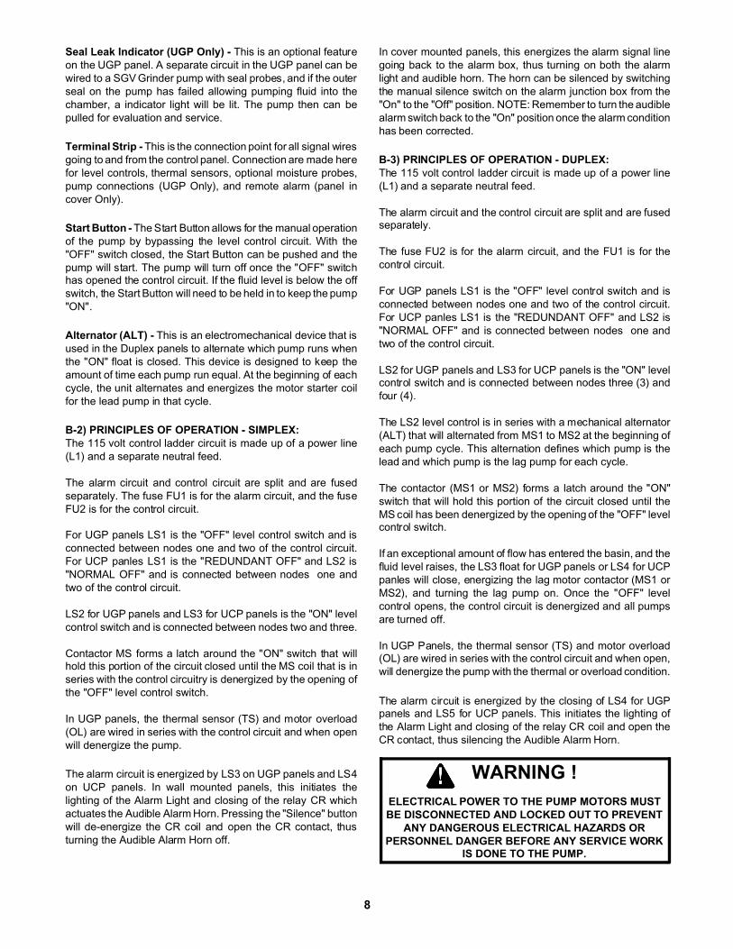
Seal Leak Indicator (UGP Only) - This is an optional featureon the UGP panel. A separate circuit in the UGP panel can bewired to a SGV Grinder pump with seal probes, and if the outerseal on the pump has failed allowing pumping fluid into thechamber, a indicator light will be lit. The pump then can bepulled for evaluation and service.
Terminal Strip - This is the connection point for all signal wiresgoing to and from the control panel. Connection are made herefor level controls, thermal sensors, optional moisture probes,pump connections (UGP Only), and remote alarm (panel incover Only).
Start Button - The Start Button allows for the manual operationof the pump by bypassing the level control circuit. With the"OFF" switch closed, the Start Button can be pushed and thepump will start. The pump will turn off once the "OFF" switchhas opened the control circuit. If the fluid level is below the offswitch, the Start Button will need to be held in to keep the pump"ON".
Alternator (ALT) - This is an electromechanical device that isused in the Duplex panels to alternate which pump runs whenthe "ON" float is closed. This device is designed to keep theamount of time each pump run equal. At the beginning of eachcycle, the unit alternates and energizes the motor starter coilfor the lead pump in that cycle.
B-2) PRINCIPLES OF OPERATION - SIMPLEX:The 115 volt control ladder circuit is made up of a power line(L1) and a separate neutral feed.
The alarm circuit and control circuit are split and are fusedseparately. The fuse FU1 is for the alarm circuit, and the fuseFU2 is for the control circuit.
For UGP panels LS1 is the "OFF" level control switch and isconnected between nodes one and two of the control circuit.For UCP panles LS1 is the "REDUNDANT OFF" and LS2 is"NORMAL OFF" and is connected between nodes one andtwo of the control circuit.
LS2 for UGP panels and LS3 for UCP panels is the "ON" levelcontrol switch and is connected between nodes two and three.
Contactor MS forms a latch around the "ON" switch that willhold this portion of the circuit closed until the MS coil that is inseries with the control circuitry is denergized by the opening ofthe "OFF" level control switch.
In UGP panels, the thermal sensor (TS) and motor overload(OL) are wired in series with the control circuit and when openwill denergize the pump.
The alarm circuit is energized by LS3 on UGP panels and LS4on UCP panels. In wall mounted panels, this initiates thelighting of the Alarm Light and closing of the relay CR whichactuates the Audible Alarm Horn. Pressing the "Silence" buttonwill de-energize the CR coil and open the CR contact, thusturning the Audible Alarm Horn off.
In cover mounted panels, this energizes the alarm signal linegoing back to the alarm box, thus turning on both the alarmlight and audible horn. The horn can be silenced by switchingthe manual silence switch on the alarm junction box from the"On" to the "Off" position. NOTE: Remember to turn the audiblealarm switch back to the "On" position once the alarm conditionhas been corrected.
B-3) PRINCIPLES OF OPERATION - DUPLEX:The 115 volt control ladder circuit is made up of a power line(L1) and a separate neutral feed.
The alarm circuit and the control circuit are split and are fusedseparately.
The fuse FU2 is for the alarm circuit, and the FU1 is for thecontrol circuit.
For UGP panels LS1 is the "OFF" level control switch and isconnected between nodes one and two of the control circuit.For UCP panles LS1 is the "REDUNDANT OFF" and LS2 is"NORMAL OFF" and is connected between nodes one andtwo of the control circuit.
LS2 for UGP panels and LS3 for UCP panels is the "ON" levelcontrol switch and is connected between nodes three (3) andfour (4).
The LS2 level control is in series with a mechanical alternator(ALT) that will alternated from MS1 to MS2 at the beginning ofeach pump cycle. This alternation defines which pump is thelead and which pump is the lag pump for each cycle.
The contactor (MS1 or MS2) forms a latch around the "ON"switch that will hold this portion of the circuit closed until theMS coil has been denergized by the opening of the "OFF" levelcontrol switch.
If an exceptional amount of flow has entered the basin, and thefluid level raises, the LS3 float for UGP panels or LS4 for UCPpanles will close, energizing the lag motor contactor (MS1 orMS2), and turning the lag pump on. Once the "OFF" levelcontrol opens, the control circuit is denergized and all pumpsare turned off.
In UGP Panels, the thermal sensor (TS) and motor overload(OL) are wired in series with the control circuit and when open,will denergize the pump with the thermal or overload condition.
The alarm circuit is energized by the closing of LS4 for UGPpanels and LS5 for UCP panels. This initiates the lighting ofthe Alarm Light and closing of the relay CR coil and open theCR contact, thus silencing the Audible Alarm Horn.
WARNING !ELECTRICAL POWER TO THE PUMP MOTORS MUSTBE DISCONNECTED AND LOCKED OUT TO PREVENT
ANY DANGEROUS ELECTRICAL HAZARDS ORPERSONNEL DANGER BEFORE ANY SERVICE WORK
IS DONE TO THE PUMP.
8

Figure 1
Figure 2
9

Figure 3
10

SECTION: C - INSTALLATION
CAUTION !ALL MODEL PUMPS AND CONTROL PANELS MUST
BE PROPERLY CONNECTED AND PROPERLYGROUNDED PER THE NATIONAL ELECTRICAL CODE,STATE, AND LOCAL CODES. IMPROPER GROUNDING
VOIDS WARRANTY.
IMPORTANTCHECK TO BE CERTAIN THAT ALL POWER IS OFF
C-1 INSTALLATION OF WALL MOUNT PANELS:1. Verify that the proper panel has been selected.
Make sure that the panel will support the Grinder HPand Voltage required, as well as have the desiredfeatures.
2. Select the desired mounting location. The UGP & UCPpanel can be mounted on the side of a building, or on a post located near the basin (see Figure 1). The panelshould be located so that easy access can be made forservicing. NOTE: The enclosure needs to be mountedon a flat surface to avoid damage due to stress. All panel alarm indicator lights and horns should bevisible/audible from the chosen location.
3. The electrical enclosure will come with either a flangeon the exterior or a set of mounting holes found underthe front cover. The proper size fasteners should beused to mount the panel. Care should be taken to insure that the panel is mounted flat. A back plate maybe required.
4. The panels use a NEMA 4X enclosure. Approvedelectrical conduit should be used to connect the wiringfrom the service panel in the home or separate electricalfeed to the panel. Conduit should also be used to connectthe panel to the basin. When using direct burial cable, theconduit should be run to 18" below grade then only cableneed be run to the basin. The basin installation manualshould be consulted to determine the number and size ofdirect burial wires required.
5. The terminal connection points are noted on theelectrical wiring diagram that is enclosed in each panel.Care should be taken to insure that all wires areconnected to the proper terminals. Note that each panel requires a separate neutral wire for the 115 voltcontrol circuitry. Be sure that a separate neutral wire ispulled from the power source to the panel. Each terminal should be torqued to the value noted in theelectrical wiring diagram.
6. The wires entering through the conduit into the panelmust be sealed to prevent condensation from buildingin the enclosure. A sprayable urethane foam should be used as a backing material in each conduit.A sealing caulk should be placed in front of the foamfor a final sealing (see Figure 2).
7. The Start-Up manual should be consulted for propertest and operations procedures of the control panel.
C-2 INSTALLATION OF PANELS IN BASIN COVER:1. Verify that the proper panel has been selected.
Make sure that the panel will support the Grinder HPand Voltage required, as well as have the desiredfeatures.
2. Select the desired mounting location for the Alarm Box.The box can be mounted on the side of a building or on apost located near the basin (See Fig. 1).The alarm box should be located so that easy accesscan be made for servicing. The location should also insure that all alarm lights and horns can be recognizedin event a problem should arise. The control panel isalready mounted in its proper orientation in the UltraCAP insert.
3. The alarm box has four tabs with mounting holes.Care should be taken to insure that the box is mounted flat using appropriate hardware. A back plate may berequired.
4. The panel and alarm box use a NEMA 4X enclosure.Approved electrical conduit should be used to connectthe wiring from the service panel in the home or separate electrical feed to the Alarm box. Conduit should also be used to connect the alarm boxto the basin. When using direct burial cable, the conduitshould be run 18" below grade or per NEC and local codes. Then only cable needs to be run to the basin. TheBasin Installation Manual should be consulted to determine the number, size and type of direct burial cable required.
Figure 4
Control PanelCord Grips
Cord Grips
11

5. The direct burial, pump, and level control wires should berun through the appropriate cord grips in the bottom of theinsert and then through the appropriate cord grips in thepanel making sure that each cord grip is tightened securely (see Fig. 4).
The connection points are noted on the electrical wiringdiagram in each panel and alarm box. Care should betaken to insure that all wires are connected in accordancewith the diagram. Note that each system requires a separate neutral wire for the 115 volt circuitry. Be sure thata separate neutral wire is pulled from the power source tothe system. Each terminal and connection should betorqued to the value noted in the electrical wiring diagram.
6. The wires entering through the conduit into the alarm boxmust be sealed to prevent condensation from buildingin the enclosure. A sprayable urethane foam should be used as a backing material in each conduit.A sealing caulk should be placed in front of the foamfor a final sealing (see Figure 2).
7. The Start-Up manual should be consulted for propertest and operations procedures of the control panel.
SECTION: D REPLACEMENT PARTS
D-1 ORDERING REPLACEMENT PARTS:When ordering replacement parts, ALWAYS furnish thefollowing information:
1. Model number or Project. (D-3)2. Part number.(D-2)3. Part description.4. Item part number.5. Quantity required.6. Shipping instructions.7. Billing Instructions.
D-2 PART NUMBER:The part number consists of a six (6) digit number, whichappears in the catalog. A one or two letter suffix may follow thisnumber to designate the design configuration. This number isused for ordering and obtaining information.
D-3 MODEL NUMBER:This designation consists of numbers and letters whichrepresent the features supplied on the panel. The Project namemay also be used here. This number is used for ordering andobtaining information.
Reference the Part number and Project or Model Numberwhen referring to the product.
2
1
12
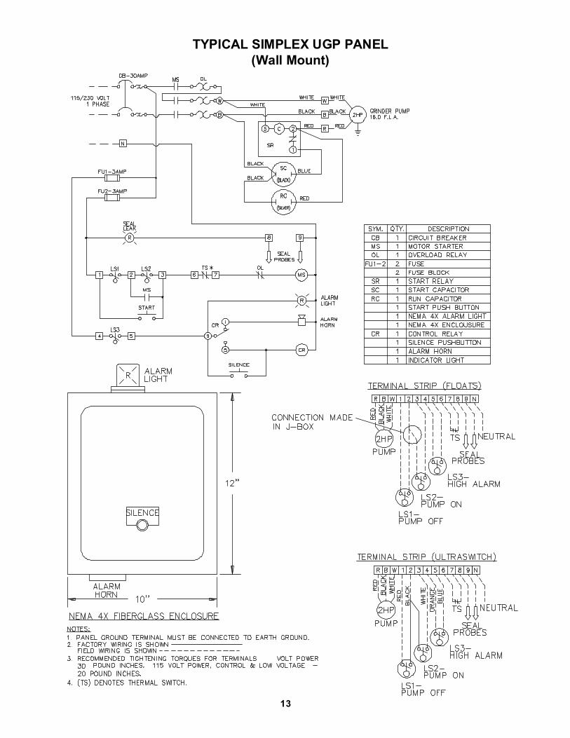
TYPICAL SIMPLEX UGP PANEL(Wall Mount)
13

TYPICAL SIMPLEX UGP-P PANEL(Cover Mounted)
14
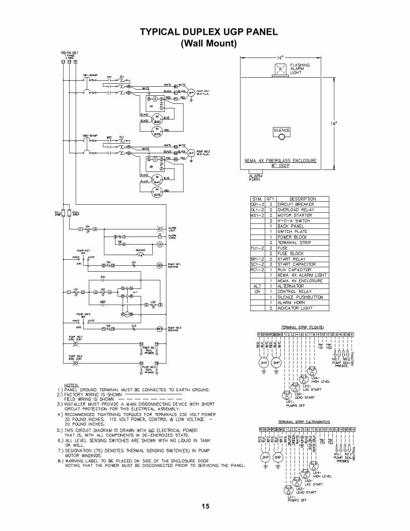
TYPICAL DUPLEX UGP PANEL(Wall Mount)
15

REPLACEMENT PARTS - 2HP
PART No. DESCRIPTION099198 Start Capacitor - Single Phase (SC)099199 Run Capacitor - Single Phase (RC)099200 Start Relay - Single Phase (START)099201 Control Fuse (FU1 & FU2)099202 Overload Relay (OL)099203 Motor Starter (MS)100195 Control Relay (CR)100199 Circuit Breaker (CB)100190 Alarm Light Lens096698 Alarm Horn Assy.100184 Alarm Light Gasket100201 Alarm Bulb
NOTE: Panels designed for a special project may have different components. Consult replacement parts list in project documentations.
TYPICAL SIMPLEX UGP PANEL(Wall Mount)
16

TYPICAL DUPLEX UGP PANEL(Wall Mount)
REPLACEMENT PARTS - 2HP
PART No. DESCRIPTION099198 Start Capacitor - Single Phase (SC)099199 Run Capacitor - Single Phase (RC)099200 Start Relay - Single Phase (START)099201 Control Fuse (FU1 & FU2)099202 Overload Relay (OL)099203 Motor Starter (MS)100195 Control Relay (CR)Contact Factory Circuit Breaker (CB)100190 Alarm Light Lens096698 Alarm Horn Assy.100184 Alarm Light Gasket100201 Alarm Bulb104408 Alternator
NOTE: Panels designed for a special project may have different components. Consult replacement parts list in project documentations.
17

TYPICAL SIMPLEX UCP PANEL(Wall Mounted)
18

TYPICAL DUPLEX UCP PANEL(Wall Mounted)
19

TYPICAL SIMPLEX UCP-P PANEL(Cover Mounted)
20

TYPICAL SIMPLEX UCP PANEL(Wall Mount)
REPLACEMENT PARTS - 1HP
PART No. DESCRIPTION099200 Start Relay - Single Phase (START)099201 Control Fuse (FU1 & FU2)099203 Motor Starter (MS)100195 Control Relay (CR)100199 Circuit Breaker (CB)100190 Alarm Light Lens096698 Alarm Horn Assy.100184 Alarm Light Gasket100201 Alarm Bulb
NOTE: Panels designed for a special project may have different components. Consult replacement parts list in project documentations.
21

TYPICAL DUPLEX UCP PANEL(Wall Mount)
REPLACEMENT PARTS - 1HP
PART No. DESCRIPTION099200 Start Relay - Single Phase (START)099201 Control Fuse (FU1 & FU2)099203 Motor Starter (MS)100195 Control Relay (CR)100199 Circuit Breaker (CB)100190 Alarm Light Lens096698 Alarm Horn Assy.100184 Alarm Light Gasket100201 Alarm Bulb104408 Alternator
NOTE: Panels designed for a special project may have different components. Consult replacement parts list in project documentations.
22

RECOMMENDED BREAKER & HEATER SIZES:
Pump Model HP Phase Volts Breaker Size Voltage Relay Start Capacitor Run Capacitor
SGV2002L 2 1 200 30 AMP *MARS 68 143mfd - 220v 20mfd - 370v
SGV2022L 2 1 230 30 AMP *MARS 68 143mfd - 220v 20mfd - 370v
SGV2062L 2 3 200 20 AMP N/R N/R N/R
SGV2032L 2 3 230 20 AMP N/R N/R N/R
SGV2042L 2 3 460 15 AMP N/R N/R N/R
SGV2052L 2 3 575 15 AMP N/R N/R N/R
SGPC1024L 1 1 230 20 AMP N/R N/R N/R
SGPC1014L 1 1 115 30 AMP N/R N/R N/R
N/R = Not Required.* MARS68 or MARS16104 or GE3ARR3J3G3 part numbers can be used.
MODELNO.
HP VOLTS PH RPM(Nom)
NEMASTARTCODE
FULLLOADAMPS
LOCKEDROTORAMPS
CORDSIZE
CORDTYPE
CORDO.D.
EMERSONWINDING
RESISTANCEMAIN--START
GEWINDING
RESISTANCEMAIN--START
SGV2002L 2.0 200 1 3450 F 17.0 53.0 10/4 SO 0.745 0.98 -- 7.29 ---------
SGV2022L 2.0 230 1 3450 F 16.0 46.0 10/4 SO 0.745 1.44 -- 6.87 1.50 -- 7.60
SGV2062L 2.0 200 3 3450 J 11.0 42.0 10/4 SO 0.745 2.57 2.40
SGV2032L 2.0 230 3 3450 H 9.0 36.0 10/4 SO 0.745 3.09 3.13
SGV2042L 2.0 460 3 3450 H 4.0 18.0 10/4 SO 0.745 12.36 12.49
SGV2052L 2.0 575 3 3450 H 3.2 14.4 10/4 SO 0.745 16.10 ----------
SGPC1014L 1.0 115 1 1750 D 18.4 38.0 10/3 SOW 0.690 0.69 -- 6.22 ----------
SGPC1024L 1.0 230 1 1750 D 9.2 17.5 10/3 SOW 0.690 2.29 -- 10.16 2.36 -- 9.33
Winding Resistance ± 5%Pump Rated For Operation at ± 10% Voltage at Motor.
23

NOTES:
24

IMPORTANT !WARRANTY REGISTRATION
Your product is covered by the enclosed Warranty. This warranty isONLY effective provided the warranty registration is completed andreturned to the Barnes Pumps, Inc. Service Department. See"Start-up/Trouble Shooting" Manual For Start-up/Warranty RegistrationForm.
IMPORTANT! If you have a claim under the provision of the warranty,contact your local Barnes Pumps, Inc. Distributor.
RETURNED GOODSRETURN OF MERCHANDISE REQUIRES A "RETURNED GOODS AUTHORIZATION".
CONTACT YOUR LOCAL CRANE PUMPS & SYSTEMS, INC. DISTRIBUTOR.
Products Returned Must Be Cleaned, Sanitized, Or Decontaminated As Necessary Prior To Shipment, To Insure That Employees Will Not Be Exposed To Health Hazards In Handling Said Material. All Applicable Laws And Regulations Shall Apply.
25

Limited 1 Year WarrantyWe warrant that products of our manufacture will be free of defects in material and workmanship under normal use andservice for twelve (12) months after notice of owner’s acceptance, but no greater than twenty-four (24) months after receiptof shipment, when installed and maintained in accordance with our instructions.This warranty gives you specific legal rights, and there may also be other rights which vary from state to state. In the eventthe product is covered by the Federal Consumer Product Warranties Law (1) the duration of any implied warrantiesassociated with the product by virtue of said law is limited to the same duration as stated herein, (2) this warranty is aLIMITED WARRANTY, and (3) no claims of any nature whatsoever shall be made against us, until the ultimate consumer,his successor, or assigns, notifies us in writing of the defect, and delivers the product and/or defective part(s) freightprepaid to our factory or nearest authorized service station. Some states do not allow limitations on how long an impliedwarranty lasts, so the above limitation may not apply. THE SOLE AND EXCLUSIVE REMEDY FOR BREACH OF ANYAND ALL WARRANTIES WITH RESPECT TO ANY PRODUCT SHALL BE TO REPLACE OR REPAIR AT OURELECTION, F.O.B. POINT OF MANUFACTURE OR AUTHORIZED REPAIR STATION, SUCH PRODUCTS AND/ORPARTS AS PROVEN DEFECTIVE. THERE SHALL BE NO FURTHER LIABILITY, WHETHER BASED ONWARRANTY, NEGLIGENCE OR OTHERWISE. Unless expressly stated otherwise, guarantees in the nature ofperformance specifications furnished in addition to the foregoing material and workmanship warranties on a productmanufactured by us, if any, are subject to laboratory tests corrected for field performance. Any additional guarantees, inthe nature of performance specifications must be in writing and such writing must be signed by our authorizedrepresentative. Due to inaccuracies in field testing if a conflict arises between the results of field testing conducted by orfor user, and laboratory tests corrected for field performance, the latter shall control. RECOMMENDATIONS FORSPECIAL APPLICATIONS OR THOSE RESULTING FROM SYSTEMS ANALYSES AND EVALUATIONS WECONDUCT WILL BE BASED ON OUR BEST AVAILABLE EXPERIENCE AND PUBLISHED INDUSTRYINFORMATION. SUCH RECOMMENDATIONS DO NOT CONSTITUTE A WARRANTY OF SATISFACTORYPERFORMANCE AND NO SUCH WARRANTY IS GIVEN.This warranty shall not apply when damage is caused by (a) improper installation, (b) improper voltage (c) lightning (d)excessive sand or other abrasive material (e) scale or corrosion build-up due to excessive chemical content. Anymodification of the original equipment will also void the warranty. We will not be responsible for loss, damage or laborcost due to interruption of service caused by defective parts. Neither will we accept charges incurred by others withoutour prior written approval.This warranty is void if our inspection reveals the product was used in a manner inconsistent with normal industry practiceand\or our specific recommendations. The purchaser is responsible for communication of all necessary informationregarding the application and use of the product. UNDER NO CIRCUMSTANCES WILL WE BE RESPONSIBLE FORANY OTHER DIRECT OR CONSEQUENTIAL DAMAGES, INCLUDING BUT NOT LIMITED TO LOST PROFITS, LOSTINCOME, LABOR CHARGES, DELAYS IN PRODUCTION, IDLE PRODUCTION, WHICH DAMAGES ARE CAUSEDBY ANY DEFECTS IN MATERIAL AND\OR WORKMANSHIP AND\OR DAMAGE OR DELAYS IN SHIPMENT. THISWARRANTY IS EXPRESSLY IN LIEU OF ANY OTHER EXPRESS OR IMPLIED WARRANTY, INCLUDING ANYWARRANTY OF MERCHANTABILITY OR FITNESS FOR A PARTICULAR PURPOSE.No rights extended under this warranty shall be assigned to any other person, whether by operation of law or otherwise,without our prior written approval.
420 Third Street/P.O. Box 603 83 West Drive, BramptonPiqua, Ohio 45356-0603 Ontario, Canada L6T 2J6Phone: (937) 778-8947 Phone: (905) 457-6223Fax: (937) 773-7157 Fax: (905) 457-2650www.cranepumps.com
PUMPS & SYSTEMS
A Crane Co. Company

** IMPORTANT ! **
WARRANTY REGISTRATION
CUSTOMER’S NAME DATE INSTALLED
ADDRESS
CITY STATE ZIP
PHONE # FAX #
DEALER’S NAME
CITY STATE ZIP
MODEL NO. SERIAL NO.
PART NO. BRAND:
FOLD HERE
IMPORTANT !WARRANTY REGISTRATION
Your product is covered by the enclosed Warranty. This warranty isONLY effective provided the warranty registration is completed andreturned to the Barnes Pumps, Inc. Service Department. See"Start-up/Trouble Shooting" Manual For Start-up/Warranty RegistrationForm.
IMPORTANT! If you have a claim under the provision of the warranty,contact your local Barnes Pumps, Inc. Distributor.
CRANE PUMPS & SYSTEMS, INC.WARRANTY SERVICE GROUP
420 THIRD STREETP.O. BOX 603
PIQUA, OHIO 45356-0603 - U.S.A.
PLACE
STAMP
HERE
FOLD HERE AND TAPE, DO NOT STAPLE
Barnes Pressure Sewer SystemsPiqua, Ohio