Embed Size (px)
Citation preview
Do not delete this graphic elements in here:
All Rights Reserved © Alcatel-Lucent @@YEAR
UMTSRNP (Radio Network Planning) Fundamentals UMTS UA07
STUDENT GUIDE
TMO54067 Issue 1
Do not delete this graphic elements in here:
All Rights Reserved © Alcatel-Lucent @@YEAR
Course objectives
Switch to notes view!
Do not delete this graphic elements in here:
All Rights Reserved © Alcatel-Lucent @@YEAR
Course objectives [cont.]
Switch to notes view!
Do not delete this graphic elements in here:
All Rights Reserved © Alcatel-Lucent @@YEAR
Self-assessment of objectives
At the end of each section you will be asked to fill this questionnaire
Please, return this sheet to the trainer at the end of the training
Switch to notes view!
Do not delete this graphic elements in here:
All Rights Reserved © Alcatel-Lucent @@YEAR
Self-assessment of objectives [cont.]
Switch to notes view!
Do not delete this graphic elements in here:
All Rights Reserved © Alcatel-Lucent @@YEAR
TMO54067 Edition 01
RNP (Radio Network Planning) Fundamentals UTRAN UA7
All Rights Reserved © Alcatel-Lucent 2009
· FundamentalsPart 1 · RNP UA7
1 · 1 · 15
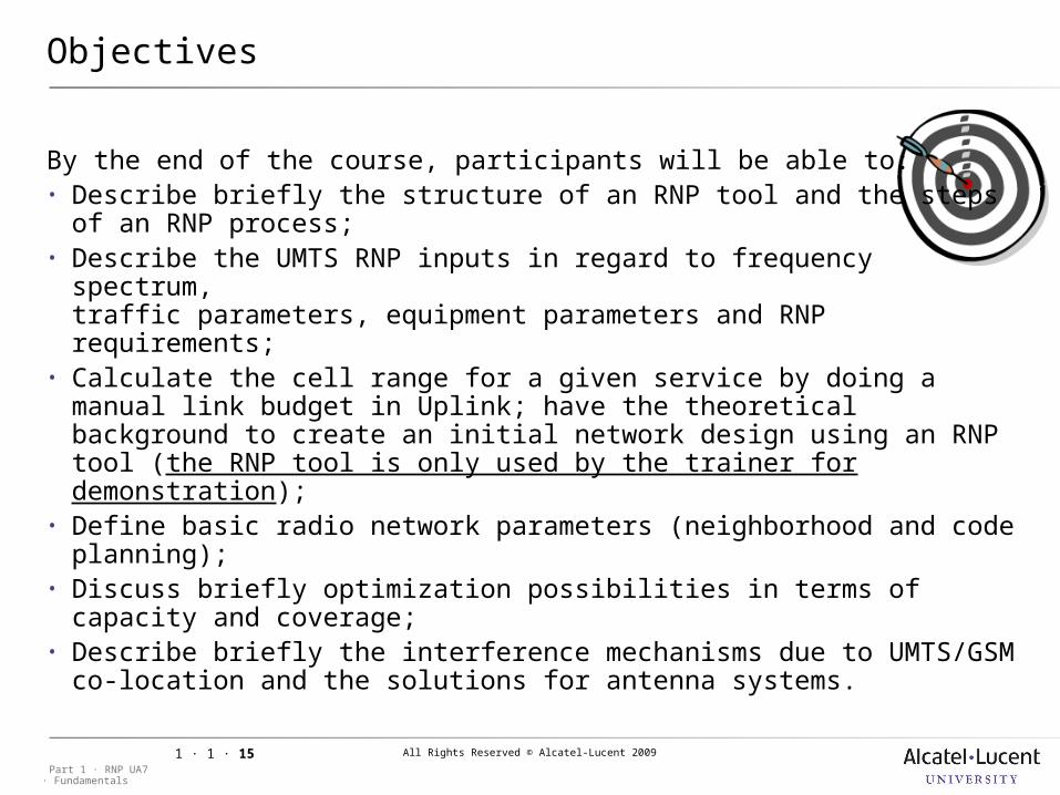
Objectives
By the end of the course, participants will be able to:• Describe briefly the structure of an RNP tool and the steps
of an RNP process;• Describe the UMTS RNP inputs in regard to frequency spectrum,
traffic parameters, equipment parameters and RNP requirements;• Calculate the cell range for a given service by doing a manual link
budget in Uplink; have the theoretical background to create an initial network design using an RNP tool (the RNP tool is only used by the trainer for demonstration);
• Define basic radio network parameters (neighborhood and code planning);
• Discuss briefly optimization possibilities in terms of capacity and coverage;
• Describe briefly the interference mechanisms due to UMTS/GSM co-location and the solutions for antenna systems.

All Rights Reserved © Alcatel-Lucent 2009
· FundamentalsPart 1 · RNP UA7
1 · 1 · 16
Objectives [cont.]
All Rights Reserved © Alcatel-Lucent 2009
· FundamentalsPart 1 · RNP UA7
1 · 1 · 19
1 UMTS Introduction
All Rights Reserved © Alcatel-Lucent 2009
· FundamentalsPart 1 · RNP UA7
1 · 1 · 20
1 UMTS Introduction
1.1 Session presentation
Objective: to get the necessary background information in regards
of UMTS basics and RNP principles for a good start in UMTS Radio Network Planning.
Prerequisites: GSM Radio Network Engineering Fundamentals Introduction to UMTS
All Rights Reserved © Alcatel-Lucent 2009
· FundamentalsPart 1 · RNP UA7
1 · 1 · 21
1.1 Session presentation
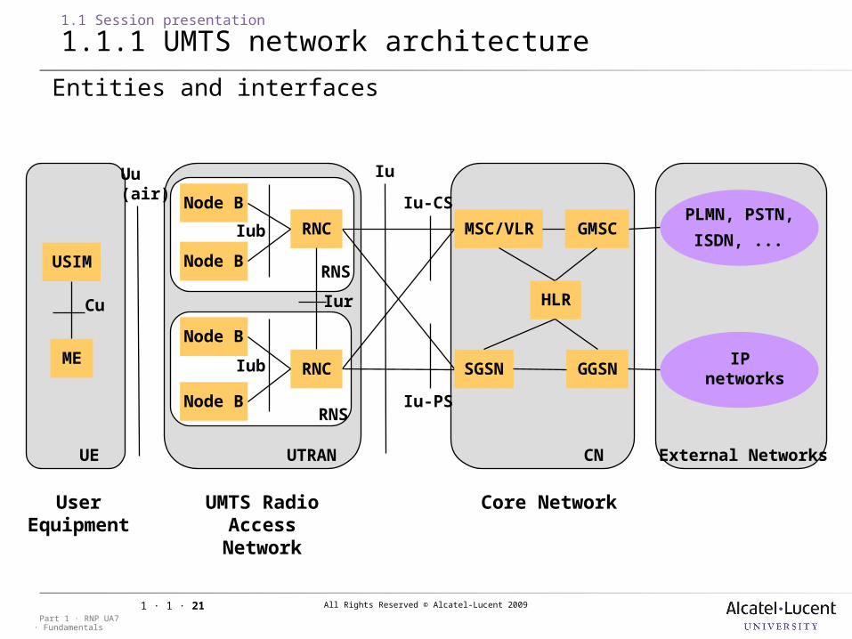
1.1.1 UMTS network architecture
Iu
PLMN, PSTN,
ISDN, ...
IP networks
External Networks
USIM
ME
Cu
UE
Uu(air)
User Equipme
nt
Node B
Node B
Iur
UTRAN
RNC
RNC
Node B
Node B
Iub
RNS
RNS
UMTS Radio Access
Network
MSC/VLR
CN
GMSC
GGSN
HLR
SGSN
Iu-CS
Iu-PS
Core Network
Entities and interfaces
Iub
All Rights Reserved © Alcatel-Lucent 2009
· FundamentalsPart 1 · RNP UA7
1 · 1 · 22
1.1 Session presentation
1.1.1 UMTS network architecture [cont.]
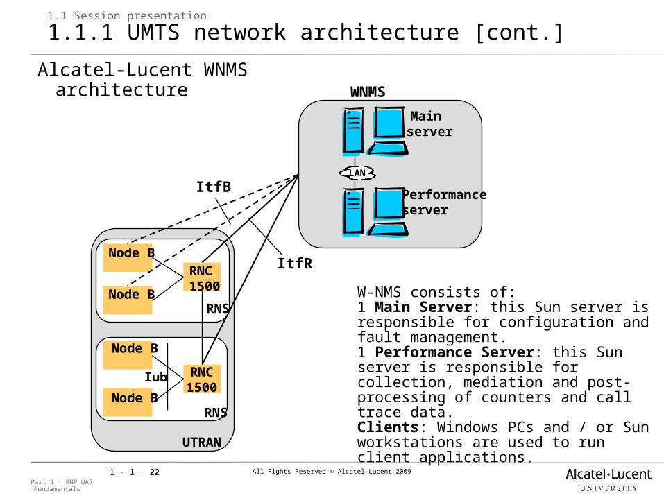
Alcatel-Lucent WNMS architecture
LAN
WNMS
Main server
Performanceserver
Node B
UTRAN
RNC 1500
Iub
RNS
RNS
ItfB
ItfR
RNC1500
Node B
Node B
Node B
W-NMS consists of:1 Main Server: this Sun server is responsible for configuration and fault management.1 Performance Server: this Sun server is responsible for collection, mediation and post-processing of counters and call trace data.Clients: Windows PCs and / or Sun workstations are used to run client applications.
All Rights Reserved © Alcatel-Lucent 2009
· FundamentalsPart 1 · RNP UA7
1 · 1 · 23
1.1 Session presentation
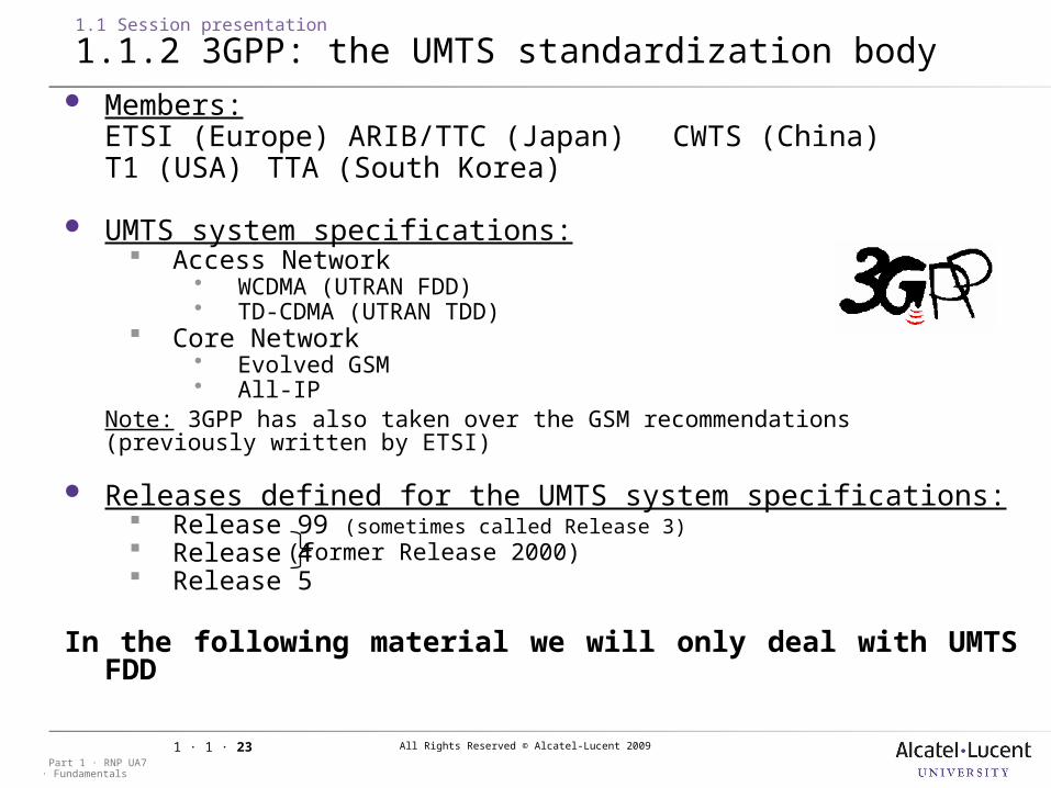
1.1.2 3GPP: the UMTS standardization body Members:
ETSI (Europe) ARIB/TTC (Japan) CWTS (China)T1 (USA) TTA (South Korea)
UMTS system specifications: Access Network
WCDMA (UTRAN FDD) TD-CDMA (UTRAN TDD)
Core Network Evolved GSM All-IP
Note: 3GPP has also taken over the GSM recommendations (previously written by ETSI)
Releases defined for the UMTS system specifications: Release 99 (sometimes called Release 3) Release 4 Release 5
In the following material we will only deal with UMTS FDD
(former Release 2000)

All Rights Reserved © Alcatel-Lucent 2009
· FundamentalsPart 1 · RNP UA7
1 · 1 · 24
1.1 Session presentation
1.1.3 3GPP UMTS specifications
3GPP UMTS specifications are classified in 15 series (numbered from 21 to 37), e.g. the serie 25 deals with UTRAN aspects.
Note: See 3GPP 21.101 for more details about the numbering scheme and an overview about all UMTS series and specifications.
Interesting specifications for UMTS Radio Network Planning:3GPP TS 25.101: "UE Radio transmission and Reception (FDD)"
3GPP TS 25.104: "UTRA (BS) FDD; Radio transmission and Reception“
3GPP TS 25.133: "Requirements for support of radio resource management (FDD)"
3GPP TS 25.141: "Base Station (BS) conformance testing (FDD)
3GPP TS 25.214: "Physical layer procedures (FDD)".
3GPP TS 25.215: "Physical layer - Measurements (FDD)”
3GPP TS 25.942: "RF system scenarios".3GPP specifications can be found under
3GPP specifications can be found under
www.3gpp.org
www.3gpp.org
All Rights Reserved © Alcatel-Lucent 2009
· FundamentalsPart 1 · RNP UA7
1 · 1 · 25
1.1 Session presentation
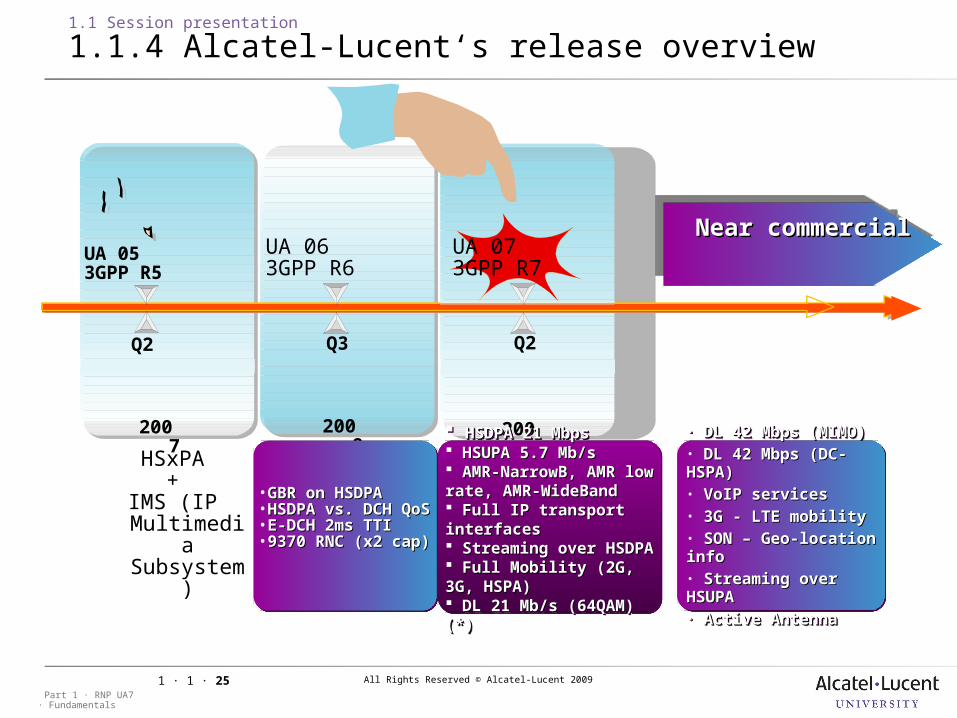
1.1.4 Alcatel-Lucent‘s release overview
March
Release 63GPP R6
March
Release 63GPP R6
Q2
2007
2008
Q3
2009
Q2
UA 053GPP R5
HSxPA+
IMS (IP Multimedia Subsystem
)
UA 063GPP R6
UA 073GPP R7
HSDPA 21 MbpsHSDPA 21 Mbps HSUPA 5.7 Mb/sHSUPA 5.7 Mb/s AMR-NarrowB, AMR AMR-NarrowB, AMR low rate, AMR-low rate, AMR-WideBandWideBand Full IP transport Full IP transport interfacesinterfaces Streaming over Streaming over HSDPAHSDPA Full Mobility (2G, 3G, Full Mobility (2G, 3G, HSPA)HSPA) DL 21 Mb/s (64QAM) DL 21 Mb/s (64QAM) (*)(*)
HSDPA 21 MbpsHSDPA 21 Mbps HSUPA 5.7 Mb/sHSUPA 5.7 Mb/s AMR-NarrowB, AMR AMR-NarrowB, AMR low rate, AMR-low rate, AMR-WideBandWideBand Full IP transport Full IP transport interfacesinterfaces Streaming over Streaming over HSDPAHSDPA Full Mobility (2G, 3G, Full Mobility (2G, 3G, HSPA)HSPA) DL 21 Mb/s (64QAM) DL 21 Mb/s (64QAM) (*)(*)
Near commercialNear commercialNear commercialNear commercial
• DL 42 Mbps (MIMO)DL 42 Mbps (MIMO)• DL 42 Mbps (DC-DL 42 Mbps (DC-HSPA)HSPA)• VoIP servicesVoIP services• 3G - LTE mobility 3G - LTE mobility • SON – Geo-location SON – Geo-location infoinfo• Streaming over Streaming over HSUPAHSUPA• Active AntennaActive Antenna
• DL 42 Mbps (MIMO)DL 42 Mbps (MIMO)• DL 42 Mbps (DC-DL 42 Mbps (DC-HSPA)HSPA)• VoIP servicesVoIP services• 3G - LTE mobility 3G - LTE mobility • SON – Geo-location SON – Geo-location infoinfo• Streaming over Streaming over HSUPAHSUPA• Active AntennaActive Antenna
•GBR on HSDPAGBR on HSDPA•HSDPA vs. DCH HSDPA vs. DCH QoSQoS•E-DCH 2ms TTIE-DCH 2ms TTI•9370 RNC (x2 9370 RNC (x2 cap)cap)
•GBR on HSDPAGBR on HSDPA•HSDPA vs. DCH HSDPA vs. DCH QoSQoS•E-DCH 2ms TTIE-DCH 2ms TTI•9370 RNC (x2 9370 RNC (x2 cap)cap)
All Rights Reserved © Alcatel-Lucent 2009
· FundamentalsPart 1 · RNP UA7
1 · 1 · 26
1.1 Session presentation
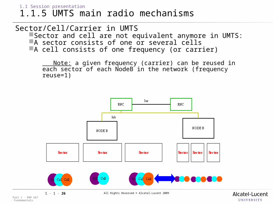
1.1.5 UMTS main radio mechanisms
Sector/Cell/Carrier in UMTSSector and cell are not equivalent anymore in UMTS:A sector consists of one or several cellsA cell consists of one frequency (or carrier)
Note: a given frequency (carrier) can be reused in each sector of each NodeB in the network (frequency reuse=1)
All Rights Reserved © Alcatel-Lucent 2009
· FundamentalsPart 1 · RNP UA7
1 · 1 · 27
1.1 Session presentation
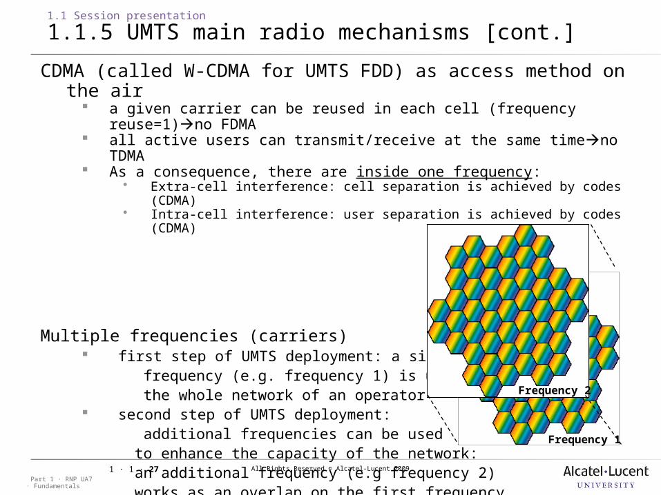
1.1.5 UMTS main radio mechanisms [cont.]
CDMA (called W-CDMA for UMTS FDD) as access method on the air a given carrier can be reused in each cell (frequency reuse=1)no FDMA all active users can transmit/receive at the same timeno TDMA As a consequence, there are inside one frequency:
Extra-cell interference: cell separation is achieved by codes (CDMA) Intra-cell interference: user separation is achieved by codes (CDMA)
Multiple frequencies (carriers) first step of UMTS deployment: a single frequency (e.g. frequency 1) is used for the whole network of an operator second step of UMTS deployment: additional frequencies can be used to enhance the capacity of the network: an additional frequency (e.g frequency 2) works as an overlap on the first frequency. Frequency 1
Frequency 2

All Rights Reserved © Alcatel-Lucent 2009
· FundamentalsPart 1 · RNP UA7
1 · 1 · 28
1.1 Session presentation
1.1.5 UMTS main radio mechanisms [cont.]
Channelization and scrambling codes (UL side)
2chc
1chc
scramblingcair
interfaceModulator
3chc
UE
Ph
ysic
al ch
an
nels
Channelization codes (spreading codes)short codes (limited number, but they can be reused with another scrambling code)code length chosen according to the bit rate of the physical channel (spreading factor)assigned by the RNC at connection setup
Scrambling codeslong codes (more than 1 million available)fixed length (no spreading)1 unique code per UE assigned by the RNC at connection setup
Bit rateA
Bit rateB
Bit rateC
3.84 Mchips/s
3.84 Mchips/s
3.84 Mchips/s 3.84 Mchips/s
.
.
.
All Rights Reserved © Alcatel-Lucent 2009
· FundamentalsPart 1 · RNP UA7
1 · 1 · 29
1.1 Session presentation
1.1.5 UMTS main radio mechanisms [cont.]
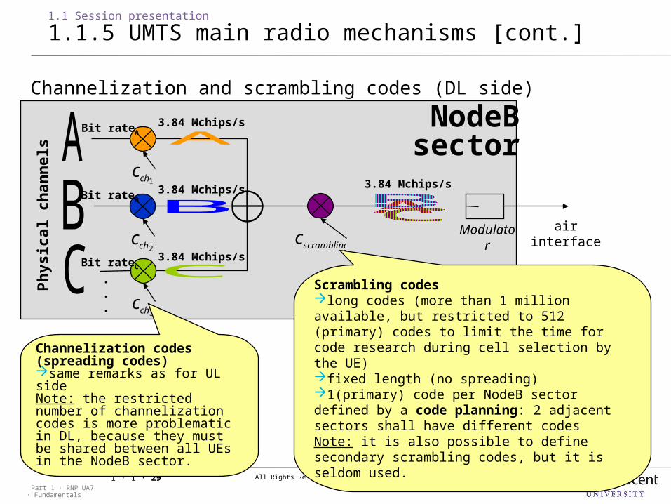
Channelization and scrambling codes (DL side)
2chc
1chc
scramblingcair interfaceModulat
or
3chc
NodeBsector
Ph
ysic
al ch
an
nels
Channelization codes (spreading codes)same remarks as for UL sideNote: the restricted number of channelization codes is more problematic in DL, because they must be shared between all UEs in the NodeB sector.
Scrambling codeslong codes (more than 1 million available, but restricted to 512 (primary) codes to limit the time for code research during cell selection by the UE)fixed length (no spreading)1(primary) code per NodeB sector defined by a code planning: 2 adjacent sectors shall have different codesNote: it is also possible to define secondary scrambling codes, but it is seldom used.
Bit rateA
Bit rateB
Bit rateC
3.84 Mchips/s
3.84 Mchips/s
3.84 Mchips/s 3.84 Mchips/s
.
.
.
All Rights Reserved © Alcatel-Lucent 2009
· FundamentalsPart 1 · RNP UA7
1 · 1 · 30
1.1 Session presentation
1.1.5 UMTS main radio mechanisms [cont.]
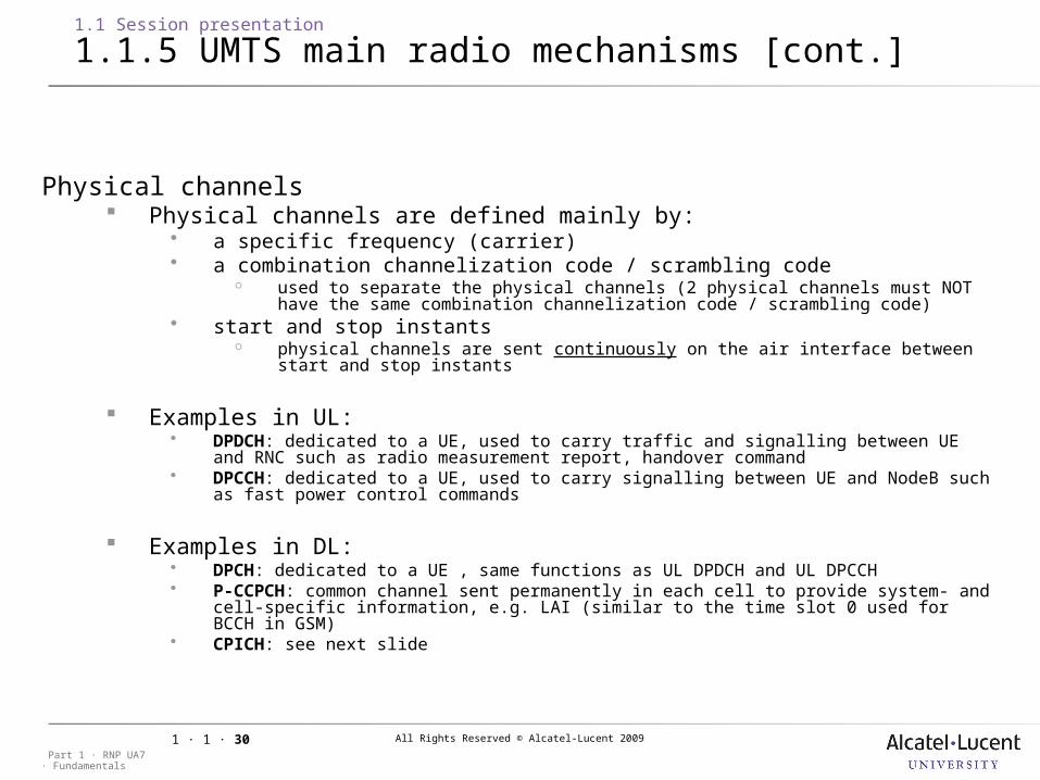
Physical channels Physical channels are defined mainly by:
a specific frequency (carrier) a combination channelization code / scrambling code
used to separate the physical channels (2 physical channels must NOT have the same combination channelization code / scrambling code)
start and stop instants physical channels are sent continuously on the air interface between start and
stop instants
Examples in UL: DPDCH: dedicated to a UE, used to carry traffic and signalling between UE and RNC such
as radio measurement report, handover command DPCCH: dedicated to a UE, used to carry signalling between UE and NodeB such as fast
power control commands
Examples in DL: DPCH: dedicated to a UE , same functions as UL DPDCH and UL DPCCH P-CCPCH: common channel sent permanently in each cell to provide system- and cell-
specific information, e.g. LAI (similar to the time slot 0 used for BCCH in GSM) CPICH: see next slide
All Rights Reserved © Alcatel-Lucent 2009
· FundamentalsPart 1 · RNP UA7
1 · 1 · 31
1.1 Session presentation
1.1.5 UMTS main radio mechanisms [cont.]
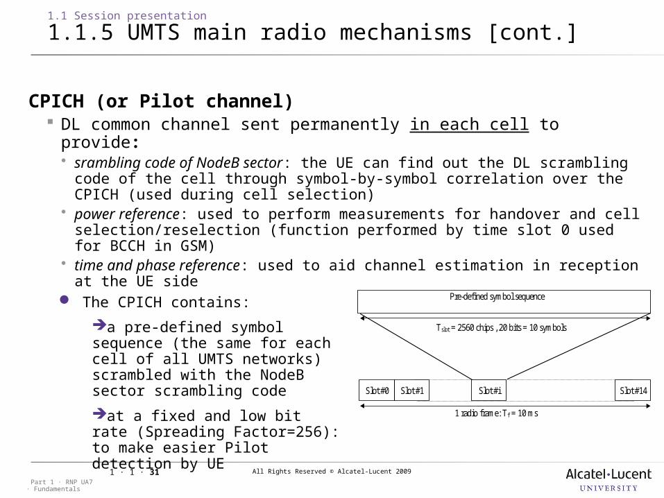
CPICH (or Pilot channel) DL common channel sent permanently in each cell to provide: srambling code of NodeB sector: the UE can find out the DL scrambling code
of the cell through symbol-by-symbol correlation over the CPICH (used during cell selection)
power reference: used to perform measurements for handover and cell selection/reselection (function performed by time slot 0 used for BCCH in GSM)
time and phase reference: used to aid channel estimation in reception at the UE side
Pre-defined symbol sequence
Slot #0 Slot #1 Slot #i Slot #14
Tslot = 2560 chips , 20 bits = 10 symbols
1 radio frame: Tf = 10 ms
The CPICH contains:
a pre-defined symbol sequence (the same for each cell of all UMTS networks) scrambled with the NodeB sector scrambling code
at a fixed and low bit rate (Spreading Factor=256): to make easier Pilot detection by UE
All Rights Reserved © Alcatel-Lucent 2009
· FundamentalsPart 1 · RNP UA7
1 · 1 · 32
1.1 Session presentation
1.1.5 UMTS main radio mechanisms [cont.]
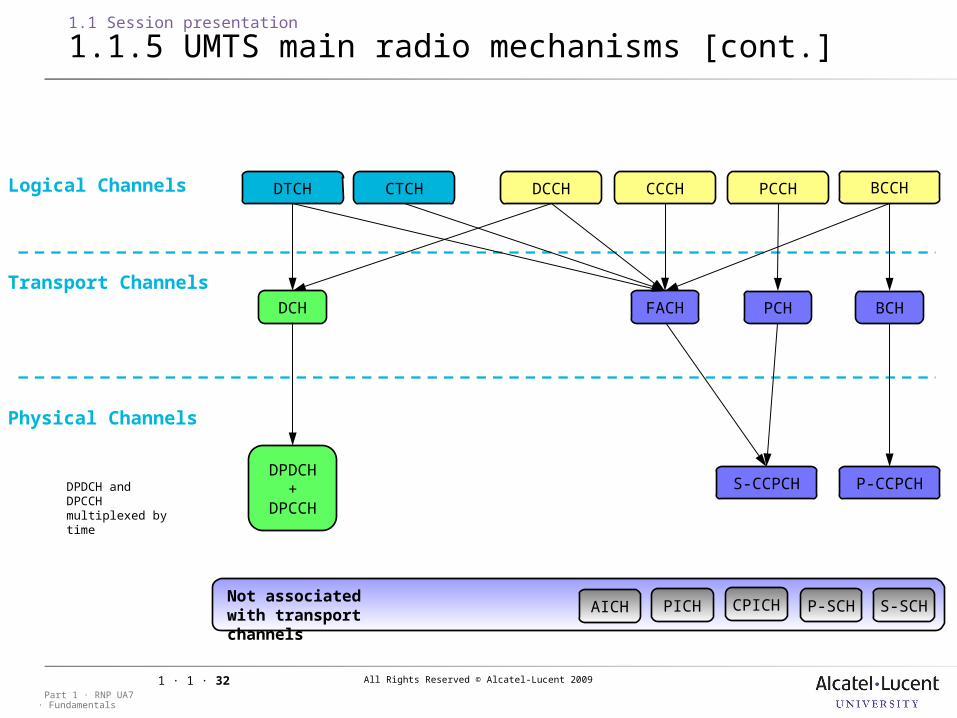
Logical Channels
AICHNot associatedwith transport channels
PICH CPICH P-SCH S-SCH
S-CCPCH P-CCPCHDPDCH
+ DPCCH
DCH BCHPCHFACH
PCCH BCCH
DPDCH and DPCCH multiplexed by time
Transport Channels
Physical Channels
DCCH CCCHCTCHDTCH
3GPP Channel mapping in HSDPA (Downlink)
All Rights Reserved © Alcatel-Lucent 2009
· FundamentalsPart 1 · RNP UA7
1 · 1 · 33
1.1 Session presentation
1.1.5 UMTS main radio mechanisms [cont.]
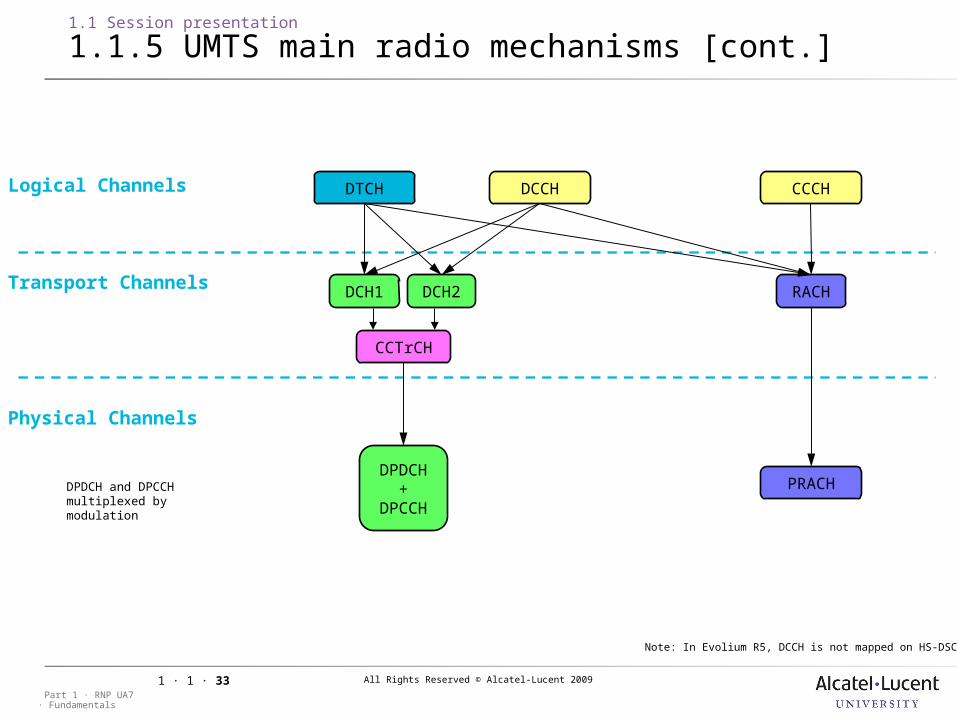
Logical Channels
PRACHDPDCH
+ DPCCH
DCH1 RACH
DPDCH and DPCCH multiplexed by modulation
CCTrCH
Transport Channels
Physical Channels
DCCH CCCHDTCH
DCH2
Note: In Evolium R5, DCCH is not mapped on HS-DSCH
3GPP Channel mapping in HSDPA (Uplink)
All Rights Reserved © Alcatel-Lucent 2009
· FundamentalsPart 1 · RNP UA7
1 · 1 · 34
1.1 Session presentation
1.1.5 UMTS main radio mechanisms [cont.]
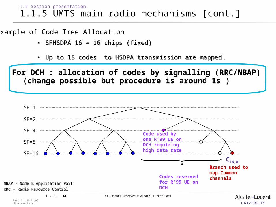
For DCH : allocation of codes by signalling (RRC/NBAP)(change possible but procedure is around 1s )
SF=8
SF=16
SF=4
SF=2
SF=1
C16,0
Branch used to map Common channels
Code used by one R’99 UE on DCH requiring high data rate
Codes reserved for R’99 UE on DCH
Example of Code Tree Allocation
NBAP - Node B Application Part
RRC - Radio Resource Control NBAP - Node B Application Part
RRC - Radio Resource Control
• SFHSDPA 16 = 16 chips (fixed)
• Up to 15 codes to HSDPA transmission are mapped.
• SFHSDPA 16 = 16 chips (fixed)
• Up to 15 codes to HSDPA transmission are mapped.
All Rights Reserved © Alcatel-Lucent 2009
· FundamentalsPart 1 · RNP UA7
1 · 1 · 35
1.1 Session presentation
1.1.5 UMTS main radio mechanisms [cont.]
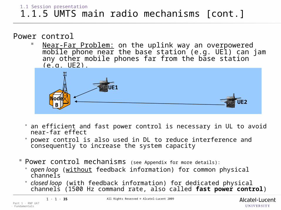
Power control Near-Far Problem: on the uplink way an overpowered mobile
phone near the base station (e.g. UE1) can jam any other mobile phones far from the base station (e.g. UE2).
NodeB
UE1
UE2
an efficient and fast power control is necessary in UL to avoid near-far effect
power control is also used in DL to reduce interference and consequently to increase the system capacity
Power control mechanisms (see Appendix for more details): open loop (without feedback information) for common physical channels closed loop (with feedback information) for dedicated physical channels
(1500 Hz command rate, also called fast power control)
All Rights Reserved © Alcatel-Lucent 2009
· FundamentalsPart 1 · RNP UA7
1 · 1 · 36
1.1 Session presentation
1.1.5 UMTS main radio mechanisms [cont.]
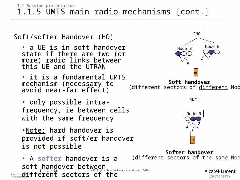
Soft/softer Handover (HO)
• a UE is in soft handover state if there are two (or more) radio links between this UE and the UTRAN
• it is a fundamental UMTS mechanism (necessary to avoid near-far effect)
• only possible intra-frequency, ie between cells with the same frequency
•Note: hard handover is provided if soft/er handover is not possible
• A softer handover is a soft handover between different sectors of the same Node B
Soft handover (different sectors of different NodeBs)
Softer handover (different sectors of the same NodeB)
RNC
Node B Node B
UE
RNC
Node B
UE
All Rights Reserved © Alcatel-Lucent 2009
· FundamentalsPart 1 · RNP UA7
1 · 1 · 37
1.1 Session presentation
1.1.5 UMTS main radio mechanisms [cont.]
Active Set (AS) and Macro Diversity Gain All cells, which are involved in soft/softer handover for a given UE
belong to the UE Active Set (AS): usual situation: about 30% of UE with at least 2 cells in their AS. up to 4(+2) cells in AS for a given UE
The different propagation paths in DL and UL lead to a diversity gain, called ‘Macro Diversity’ gain: UL
one physical signal sent by one UE and received by two different cells soft handover: selection on frame basis (each 10ms) in RNC softer handover: Maximum Ratio Combining(MRC) in NodeB
DL two physical signals (with the same content) sent by two different cells and received
by one UE soft/softer handover: MRC in UE
All Rights Reserved © Alcatel-Lucent 2009
· FundamentalsPart 1 · RNP UA7
1 · 1 · 38
1 UMTS Introduction
1.2 HSXPA overview
This section will take a look at the main concepts of HSDPA and HSUPA.
All Rights Reserved © Alcatel-Lucent 2009
· FundamentalsPart 1 · RNP UA7
1 · 1 · 39
1.2 HSXPA overview
1.2.1 HSDPA
HSDPA: High Speed Downlink Packet Access
Part of 3GPP Release 5 (R5) and later releases
Purpose: Enhance 3G Mobile systems by offering higher data rates in the Downlink Direction
Direct evolution of 3GPP R’99 networks (UMTS)
To further extend your UMTS network performances
All Rights Reserved © Alcatel-Lucent 2009
· FundamentalsPart 1 · RNP UA7
1 · 1 · 40
1.2 HSXPA overview
1.2.2 New physical channels
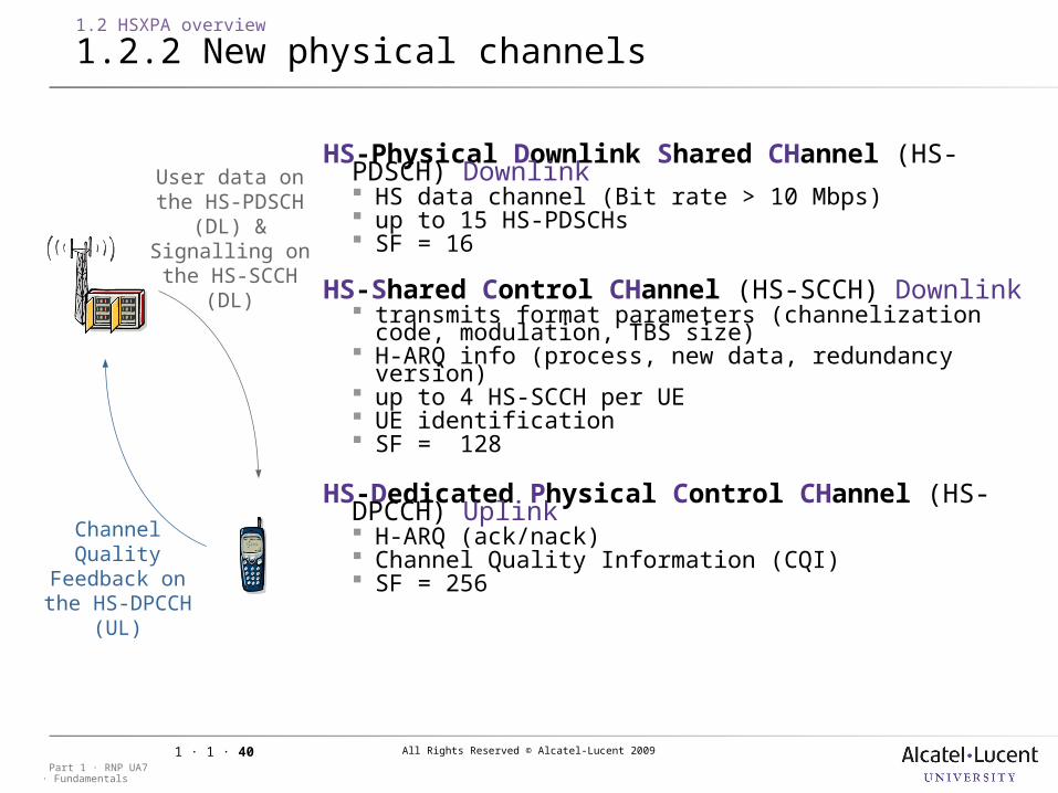
HS-Physical Downlink Shared CHannel (HS-PDSCH) Downlink HS data channel (Bit rate > 10 Mbps) up to 15 HS-PDSCHs SF = 16
HS-Shared Control CHannel (HS-SCCH) Downlink transmits format parameters (channelization code,
modulation, TBS size) H-ARQ info (process, new data, redundancy version) up to 4 HS-SCCH per UE UE identification SF = 128
HS-Dedicated Physical Control CHannel (HS-DPCCH) Uplink H-ARQ (ack/nack) Channel Quality Information (CQI) SF = 256Channel Quality
Feedback on the HS-DPCCH (UL)
User data on the HS-PDSCH (DL)
&Signalling on the
HS-SCCH (DL)
All Rights Reserved © Alcatel-Lucent 2009
· FundamentalsPart 1 · RNP UA7
1 · 1 · 41
1.2 HSXPA overview
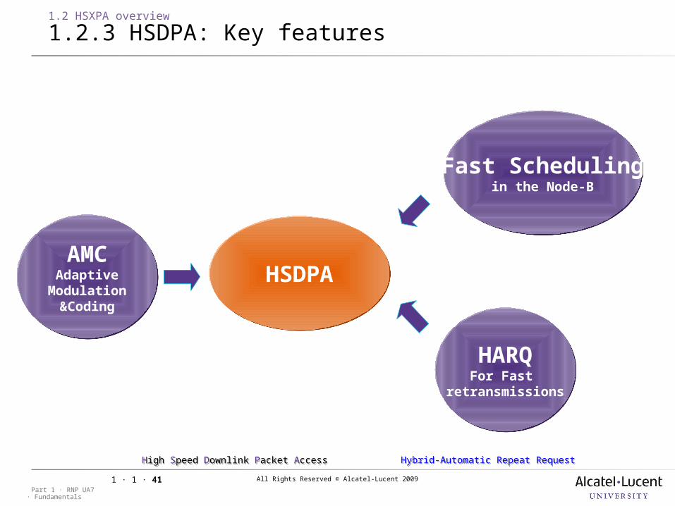
1.2.3 HSDPA: Key features
HSDPAHSDPAAMC
AdaptiveModulation
&Coding
AMCAdaptive
Modulation&Coding
HARQFor Fast
retransmissions
HARQFor Fast
retransmissions
Fast Schedulingin the Node-B
Fast Schedulingin the Node-B
Hybrid-Automatic Repeat RequestHybrid-Automatic Repeat RequestHigh Speed Downlink Packet AccessHigh Speed Downlink Packet Access
All Rights Reserved © Alcatel-Lucent 2009
· FundamentalsPart 1 · RNP UA7
1 · 1 · 42
1.2 HSXPA overview
1.2.3 HSDPA: Key features [cont.]
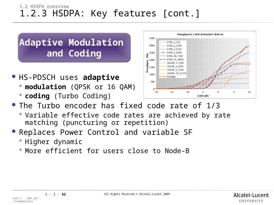
HS-PDSCH uses adaptive modulation (QPSK or 16 QAM) coding (Turbo Coding)
The Turbo encoder has fixed code rate of 1/3 Variable effective code rates are achieved by rate matching
(puncturing or repetition) Replaces Power Control and variable SF Higher dynamic More efficient for users close to Node-B
Adaptive Modulation and Coding
Adaptive Modulation and Coding
Throughput vs. C/(I+N) [Vehicular A 30 km/h]
0
500
1000
1500
2000
2500
3000
3500
-20 -15 -10 -5 0 5 10
C/(I+N) [dB]
Th
rou
gh
pu
t [K
bp
s]
QPSK_1_724
QPSK_2_1430
QPSK_3_2159
QPSK_5_3630
QPSK_10_7168
QPSK_15_10821
16QAM_1_1430
16QAM_2_2876
16QAM_5_7168
16QAM_15_21754
Envelope
All Rights Reserved © Alcatel-Lucent 2009
· FundamentalsPart 1 · RNP UA7
1 · 1 · 43
1.2 HSXPA overview
1.2.3 HSDPA: Key features [cont.]
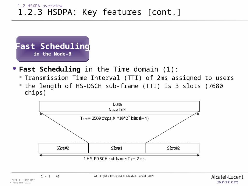
Fast Scheduling in the Time domain (1): Transmission Time Interval (TTI) of 2ms assigned to users the length of HS-DSCH sub-frame (TTI) is 3 slots (7680 chips)
Slot #0 Slot#1 Slot #2
Tslot = 2560 chips, M*10*2 k bits (k=4)
DataNdata1 bits
1 HS-PDSCH subframe: T f = 2 ms
Fast Schedulingin the Node-B
Fast Schedulingin the Node-B
All Rights Reserved © Alcatel-Lucent 2009
· FundamentalsPart 1 · RNP UA7
1 · 1 · 44
1.2 HSXPA overview
1.2.3 HSDPA: Key features [cont.]
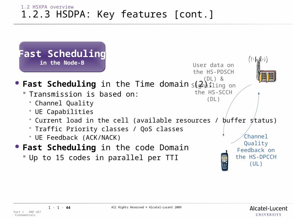
Fast Scheduling in the Time domain (2): Transmission is based on: Channel Quality UE Capabilities Current load in the cell (available resources / buffer status) Traffic Priority classes / QoS classes UE Feedback (ACK/NACK)
Fast Scheduling in the code Domain Up to 15 codes in parallel per TTI
Fast Schedulingin the Node-B
Fast Schedulingin the Node-B
Channel Quality Feedback on the HS-DPCCH (UL)
User data on the HS-PDSCH (DL)
&Signalling on the
HS-SCCH (DL)
All Rights Reserved © Alcatel-Lucent 2009
· FundamentalsPart 1 · RNP UA7
1 · 1 · 45
1.2 HSXPA overview
1.2.3 HSDPA: Key features [cont.]
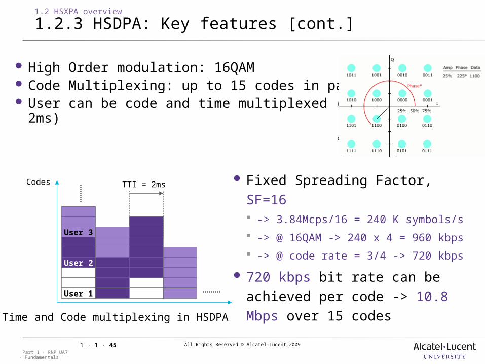
High Order modulation: 16QAM Code Multiplexing: up to 15 codes in parallel User can be code and time multiplexed (TTI= 2ms)
1011 1001 0001 0011
1010 1000 0000 0010
1110 1100 0100 0110
1111 1101 0101 0111
i2 i2
i1
q1
q2
q2
0.4472 1.34160.4472
1.3416
Codes TTI = 2ms
User 1
User 2
User 3
Time and Code multiplexing in HSDPA
Fixed Spreading Factor, SF=16 -> 3.84Mcps/16 = 240 K symbols/s
-> @ 16QAM -> 240 x 4 = 960 kbps
-> @ code rate = 3/4 -> 720 kbps
720 kbps bit rate can be achieved per code -> 10.8 Mbps over 15 codes
All Rights Reserved © Alcatel-Lucent 2009
· FundamentalsPart 1 · RNP UA7
1 · 1 · 46
1.2 HSXPA overview
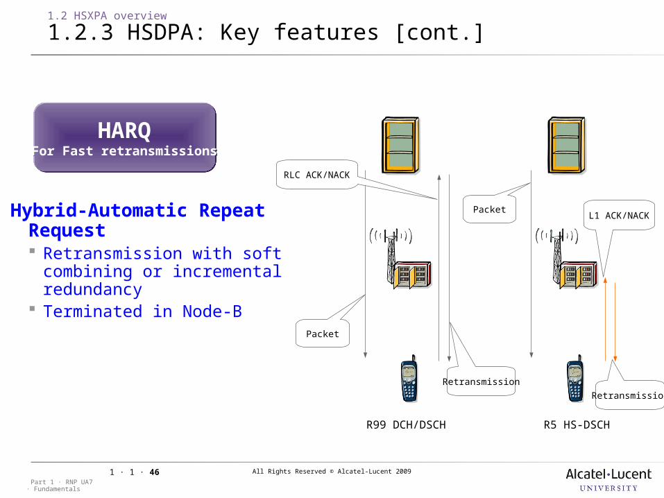
1.2.3 HSDPA: Key features [cont.]
Hybrid-Automatic Repeat Request Retransmission with soft combining
or incremental redundancy Terminated in Node-B
HARQFor Fast retransmissions
HARQFor Fast retransmissions
R5 HS-DSCHR99 DCH/DSCH
Packet
RLC ACK/NACK
Retransmission
PacketL1 ACK/NACK
Retransmission
All Rights Reserved © Alcatel-Lucent 2009
· FundamentalsPart 1 · RNP UA7
1 · 1 · 47
1.2 HSXPA overview
1.2.3 HSDPA: Key features [cont.]
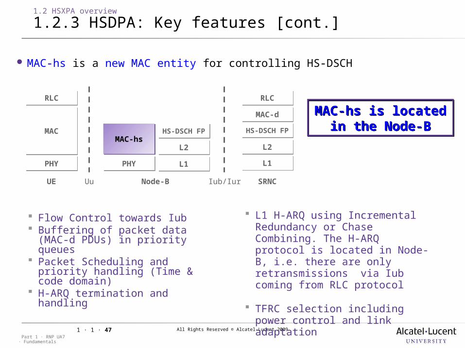
MAC-hs is a new MAC entity for controlling HS-DSCH
PHYPHY PHYPHY L1L1 L1L1
L2L2 L2L2
HS-DSCH FPHS-DSCH FP HS-DSCH FPHS-DSCH FPHS-DSCH FPHS-DSCH FP
MAC-dMAC-d
RLCRLCRLCRLC
MACMAC HS-DSCH FPHS-DSCH FPMAC-hsMAC-hs
Uu Iub/Iur SRNCNode-BUE
Flow Control towards Iub Buffering of packet data (MAC-d
PDUs) in priority queues Packet Scheduling and priority
handling (Time & code domain) H-ARQ termination and handling
L1 H-ARQ using Incremental Redundancy or Chase Combining. The H-ARQ protocol is located in Node-B, i.e. there are only retransmissions via Iub coming from RLC protocol
TFRC selection including power control and link adaptation
MAC-hs is located in the Node-B
MAC-hs is located in the Node-B
All Rights Reserved © Alcatel-Lucent 2009
· FundamentalsPart 1 · RNP UA7
1 · 1 · 48
1.2 HSXPA overview
1.2.4 Terminal categories
HS-DSCH category
Maximum number of HS-DSCH codes
received
Modulation supported (QPSK and/or 16-QAM)
Maximum bit rate
(in Mbps)
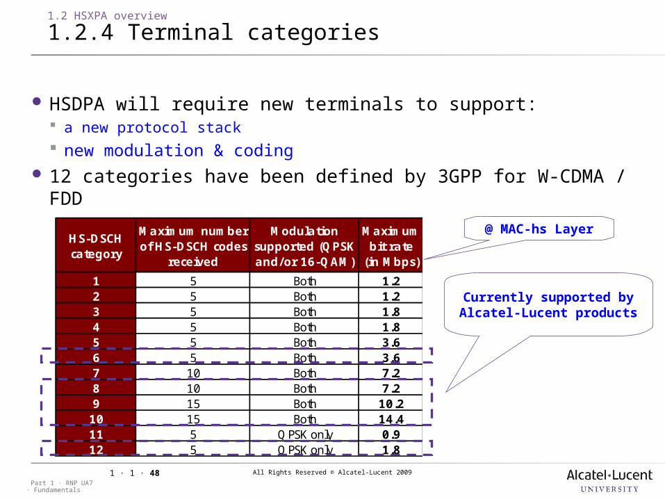
1 5 Both 1.22 5 Both 1.23 5 Both 1.84 5 Both 1.85 5 Both 3.66 5 Both 3.67 10 Both 7.28 10 Both 7.29 15 Both 10.210 15 Both 14.411 5 QPSK only 0.912 5 QPSK only 1.8
HSDPA will require new terminals to support: a new protocol stack new modulation & coding
12 categories have been defined by 3GPP for W-CDMA / FDD
Currently supported by Alcatel-Lucent products
@ MAC-hs Layer
All Rights Reserved © Alcatel-Lucent 2009
· FundamentalsPart 1 · RNP UA7
1 · 1 · 49
FDD HS-DSCH physical layer categories – Rel 8
HS-DSCH category
Maximum nb of HS-DSCH
codes received
Nb of HS-DSCH
transport block per TTI
Maximum nb of bits of an HS-DSCH transport block received within
a TTI
Supported modulations
without MIMO operation
Supported modulations simultaneous
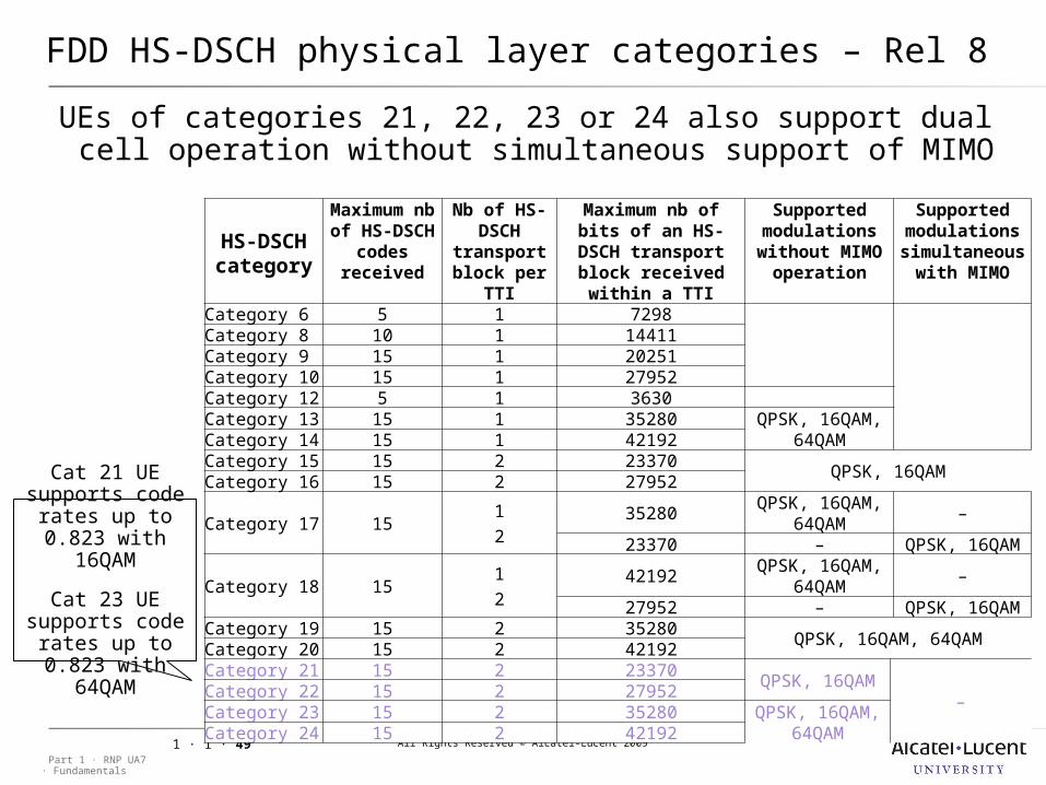
with MIMOCategory 6 5 1 7298Category 8 10 1 14411Category 9 15 1 20251Category 10 15 1 27952Category 12 5 1 3630Category 13 15 1 35280 QPSK, 16QAM,
64QAMCategory 14 15 1 42192Category 15 15 2 23370
QPSK, 16QAMCategory 16 15 2 27952
Category 17 151
235280
QPSK, 16QAM, 64QAM
–
23370 – QPSK, 16QAM
Category 18 151
242192
QPSK, 16QAM, 64QAM
–
27952 – QPSK, 16QAMCategory 19 15 2 35280
QPSK, 16QAM, 64QAMCategory 20 15 2 42192Category 21 15 2 23370
QPSK, 16QAM–
Category 22 15 2 27952Category 23 15 2 35280 QPSK, 16QAM,
64QAMCategory 24 15 2 42192
UEs of categories 21, 22, 23 or 24 also support dual cell operation without simultaneous support of MIMO
Cat 21 UE supports code
rates up to 0.823 with 16QAM
Cat 23 UE supports code
rates up to 0.823 with 64QAM
All Rights Reserved © Alcatel-Lucent 2009
· FundamentalsPart 1 · RNP UA7
1 · 1 · 50
1.2 HSXPA overview
1.2.5 CQI table
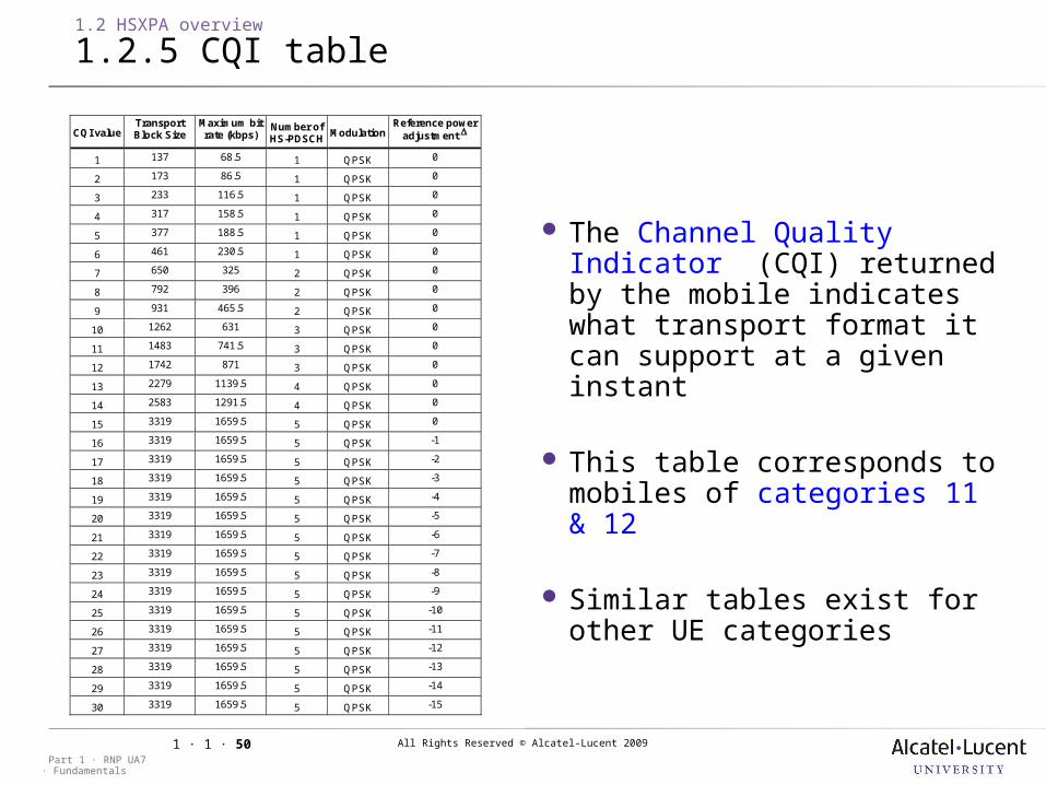
The Channel Quality Indicator (CQI) returned by the mobile indicates what transport format it can support at a given instant
This table corresponds to mobiles of categories 11 & 12
Similar tables exist for other UE categories
CQI valueTransportBlock Size
Maximum bitrate (kbps)
Number ofHS-PDSCH
ModulationReference power
adjustment
1 137 68.5 1 QPSK 0
2 173 86.5 1 QPSK 0
3 233 116.5 1 QPSK 0
4 317 158.5 1 QPSK 0
5 377 188.5 1 QPSK 0
6 461 230.5 1 QPSK 0
7 650 325 2 QPSK 0
8 792 396 2 QPSK 0
9 931 465.5 2 QPSK 0
10 1262 631 3 QPSK 0
11 1483 741.5 3 QPSK 0
12 1742 871 3 QPSK 0
13 2279 1139.5 4 QPSK 0
14 2583 1291.5 4 QPSK 0
15 3319 1659.5 5 QPSK 0
16 3319 1659.5 5 QPSK -1
17 3319 1659.5 5 QPSK -2
18 3319 1659.5 5 QPSK -3
19 3319 1659.5 5 QPSK -4
20 3319 1659.5 5 QPSK -5
21 3319 1659.5 5 QPSK -6
22 3319 1659.5 5 QPSK -7
23 3319 1659.5 5 QPSK -8
24 3319 1659.5 5 QPSK -9
25 3319 1659.5 5 QPSK -10
26 3319 1659.5 5 QPSK -11
27 3319 1659.5 5 QPSK -12
28 3319 1659.5 5 QPSK -13
29 3319 1659.5 5 QPSK -14
30 3319 1659.5 5 QPSK -15
All Rights Reserved © Alcatel-Lucent 2009
· FundamentalsPart 1 · RNP UA7
1 · 1 · 51
1.2 HSXPA overview
1.2.6 Summary of HSDPA key benefits
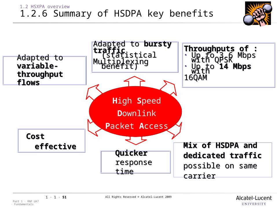
Throughputs of :• Up to 3.6 Mbps with
QPSK• Up to 14 Mbps with 16QAM
Throughputs of :• Up to 3.6 Mbps with
QPSK• Up to 14 Mbps with 16QAM
Adapted to variable-throughput flows
Adapted to variable-throughput flows
Quicker response timeQuicker response time
Mix of HSDPA and dedicated traffic possible on same carrier
Mix of HSDPA and dedicated traffic possible on same carrier
Cost effectiveCost effective
High Speed
Downlink
Packet Access
Adapted to burstytraffic (statisticalMultiplexing benefit)
Adapted to burstytraffic (statisticalMultiplexing benefit)
All Rights Reserved © Alcatel-Lucent 2009
· FundamentalsPart 1 · RNP UA7
1 · 1 · 52
1 UMTS Introduction
1.3 HSUPA basics
HSUPA: High Speed Uplink Packet Access
3GPP release 6 feature Also called Enhanced DCH or Enhanced Uplink
Purposes: Boost uplink data performances in terms of higher
throughput, reduced delay and higher capacity Balance uplink traffic performance with downlink HSDPA Mandatory step for VoIP
All Rights Reserved © Alcatel-Lucent 2009
· FundamentalsPart 1 · RNP UA7
1 · 1 · 53
1.3 HSUPA basics
1.3.1 New Physical Channels
HSUPAUE
128)
256)
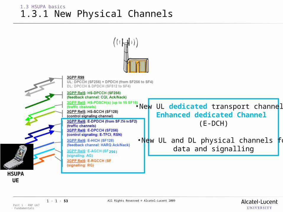
•New UL dedicated transport channel: Enhanced dedicated Channel
(E-DCH)
•New UL and DL physical channels fordata and signalling
All Rights Reserved © Alcatel-Lucent 2009
· FundamentalsPart 1 · RNP UA7
1 · 1 · 54
1.3 HSUPA basics
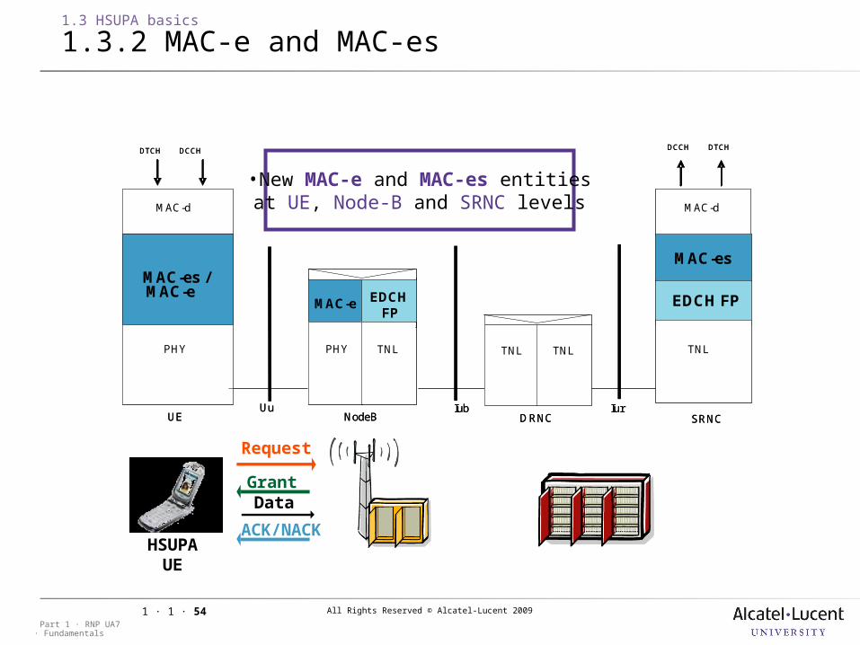
1.3.2 MAC-e and MAC-es
•New MAC-e and MAC-es entities at UE, Node-B and SRNC levels
Request
GrantData
ACK/NACKHSUP
AUE
PHY PHY
EDCHFP
EDCH FP
IubUE NodeB
Uu
DCCH DTCH
TNL TNL
DTCH DCCH
MAC
SRNC
MAC-d
MAC-e
MAC-d
MAC-es /MAC-e
MAC-es
Iur
TNL TNL
DRNC
PHY PHY
EDCHFP
EDCH FP
IubUE NodeB
Uu
DCCH DTCH
TNL TNL
DTCH DCCH
MAC
SRNC
MAC-d
MAC-e
MAC-d
MAC-es /MAC-e
MAC-es
Iur
TNL TNL
DRNC
All Rights Reserved © Alcatel-Lucent 2009
· FundamentalsPart 1 · RNP UA7
1 · 1 · 55
1.3 HSUPA basics
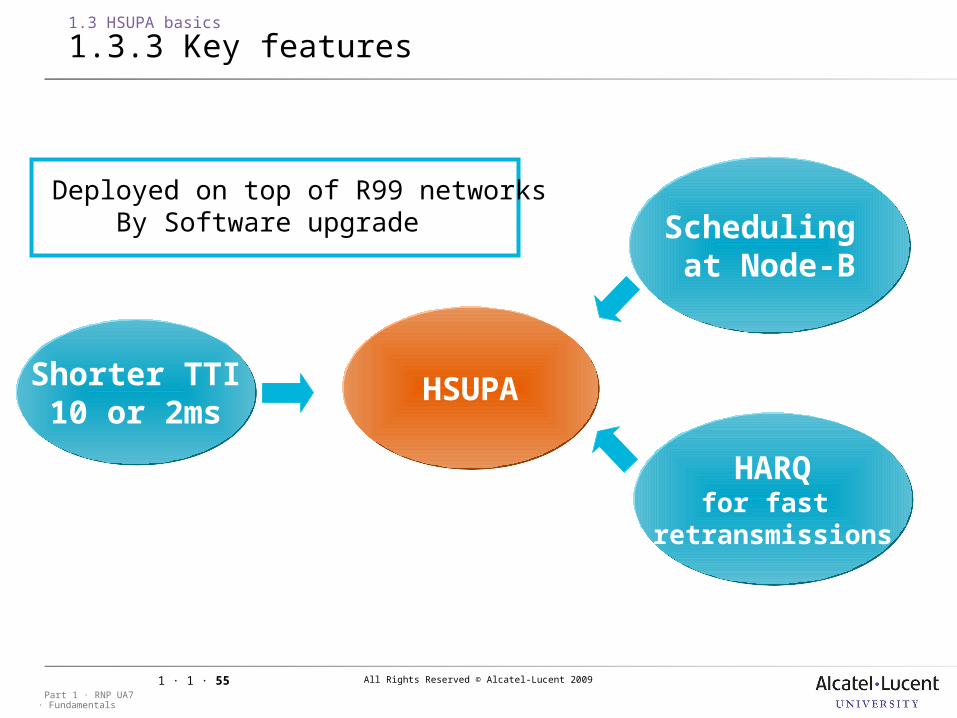
1.3.3 Key features
HSUPAHSUPAShorter TTI10 or 2ms
Shorter TTI10 or 2ms
HARQfor fast
retransmissions
HARQfor fast
retransmissions
Scheduling at Node-B
Scheduling at Node-B
NB: No adaptive modulation in HSUPA (BPSK as in DCH – QPSK is used when SF<4)
Deployed on top of R99 networksBy Software upgrade
All Rights Reserved © Alcatel-Lucent 2009
· FundamentalsPart 1 · RNP UA7
1 · 1 · 56
1.3 HSUPA basics
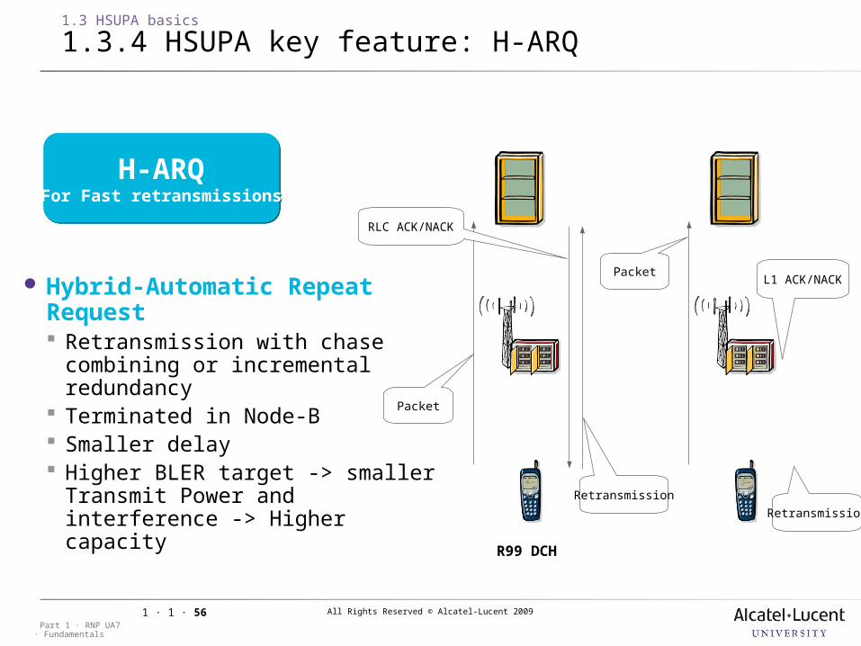
1.3.4 HSUPA key feature: H-ARQ
Hybrid-Automatic Repeat Request Retransmission with chase
combining or incremental redundancy
Terminated in Node-B Smaller delay Higher BLER target -> smaller
Transmit Power and interference -> Higher capacity
H-ARQFor Fast retransmissions
H-ARQFor Fast retransmissions
R6 E-DCHR99 DCH
Packet
RLC ACK/NACK
Retransmission
PacketL1 ACK/NACK
Retransmission
All Rights Reserved © Alcatel-Lucent 2009
· FundamentalsPart 1 · RNP UA7
1 · 1 · 57
1.3 HSUPA basics
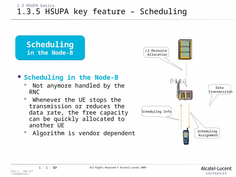
1.3.5 HSUPA key feature – Scheduling
Schedulingin the Node-BSchedulingin the Node-B
R6 E-DCH
Data transmission
L3 Resource Allocation
Scheduling Info
Scheduling Assignment
Scheduling in the Node-B Not anymore handled by the RNC Whenever the UE stops the
transmission or reduces the data rate, the free capacity can be quickly allocated to another UE
Algorithm is vendor dependent

All Rights Reserved © Alcatel-Lucent 2009
· FundamentalsPart 1 · RNP UA7
1 · 1 · 58
1.3 HSUPA basics
1.3.5 HSUPA key feature – Scheduling [cont.]
Schedulingin the Node-BSchedulingin the Node-B
DCH services (eg voice and visio)
UE 2
UE 1
UE 1
UE 2
UE 3
UE 1
UE 2
UE 3UE 1
TTI 0 TTI 1 TTI 2 TTI 3
RoT
Time
Maximum allowable noise rise
Shared resource is the total Uplink interference eg Rise over Thermal Noise, RoT or interference margin
The Node B controls the allocation of this margin Selects the best Transport Format
Combination (TFC) for a given UE according to the available interference margin (left over R’99) and schedules the UE
All Rights Reserved © Alcatel-Lucent 2009
· FundamentalsPart 1 · RNP UA7
1 · 1 · 59
1.3 HSUPA basics
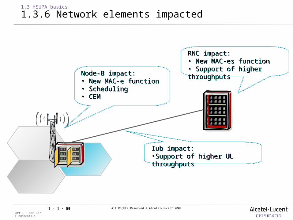
1.3.6 Network elements impacted
Iub impact:•Support of higher UL throughputs
Iub impact:•Support of higher UL throughputs
RNC impact:• New MAC-es function• Support of higher throughputs
RNC impact:• New MAC-es function• Support of higher throughputsNode-B impact:
• New MAC-e function• Scheduling• CEM
Node-B impact:• New MAC-e function• Scheduling• CEM
All Rights Reserved © Alcatel-Lucent 2009
· FundamentalsPart 1 · RNP UA7
1 · 1 · 60
1.3 HSUPA basics
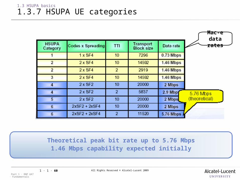
1.3.7 HSUPA UE categories
Theoretical peak bit rate up to 5.76 Mbps1.46 Mbps capability expected initially
Theoretical peak bit rate up to 5.76 Mbps1.46 Mbps capability expected initially
Mac-e data rates
All Rights Reserved © Alcatel-Lucent 2009
· FundamentalsPart 1 · RNP UA7
1 · 1 · 61
1.3 HSUPA basics
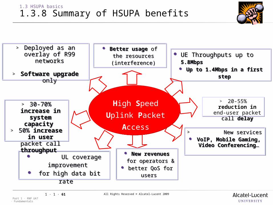
1.3.8 Summary of HSUPA benefits
UE Throughputs up to 5.8Mbps
Up to 1.4Mbps in a first step
UE Throughputs up to 5.8Mbps
Up to 1.4Mbps in a first step
> New services VoIP, Mobile Gaming,
Video Conferencing…
> New services VoIP, Mobile Gaming,
Video Conferencing…
UL coverage improvement
for high data bit rate
UL coverage improvement
for high data bit rate
High Speed
Uplink Packet
Access
> Deployed as an overlay of R99 networks
> Software upgrade only
> Deployed as an overlay of R99 networks
> Software upgrade only
Better usage of the resources
(interference)
Better usage of the resources
(interference)
New revenues for operators &
better QoS for users
New revenues for operators &
better QoS for users
> 30-70% increase in
system capacity
> 50% increase in user packet
call throughput
> 30-70% increase in
system capacity
> 50% increase in user packet
call throughput
> 20-55% reduction in
end-user packet call delay
> 20-55% reduction in
end-user packet call delay
All Rights Reserved © Alcatel-Lucent 2009
· FundamentalsPart 1 · RNP UA7
1 · 1 · 62
1 UMTS Introduction
1.4 UMTS RNP notations and principles
Objective: to be able to understand the vocabulary and notations* used in
this course in regards of UMTS planning
* unfortunately, UMTS RNP notations are not clearly standardized, so that the meaning of a notation can be quite different from one reference to another one.
All Rights Reserved © Alcatel-Lucent 2009
· FundamentalsPart 1 · RNP UA7
1 · 1 · 63
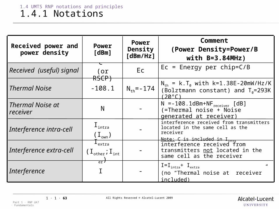
I=Iintra+ Iextra
(no “Thermal noise at receiver” included)
I Interference
interference received from transmitters not located in the same cell as the receiver
Iextra
(Iother;Iinter)Interference extra-cell
interference received from transmitters located in the same cell as the receiverNote: C is included in Iintra
Iintra
(Iown)Interference intra-cell
N =-108.1dBm+NFreceiver [dB] (=Thermal noise + Noise generated at receiver)
NThermal Noise at receiver
Nth = k.T0 with k=1.38E-20mW/Hz/K (Bolztmann constant) and T0=293K (20°C)
-108.1Thermal Noise
Ec = Energy per chip=C/BC (or RSCP)
Received (useful) signal
Comment (Power Density=Power/B
with B=3.84MHz)
Power [dBm]
Received power and power density
-
-
-
-
Nth=-174
Ec
Power Density [dBm/Hz
]
1.4 UMTS RNP notations and principles
1.4.1 Notations
All Rights Reserved © Alcatel-Lucent 2009
· FundamentalsPart 1 · RNP UA7
1 · 1 · 64
Received power and power
density
Power [dBm]
Power Density [dBm/Hz
]
Comment Power Density=Power/B
with B=3.84MHz
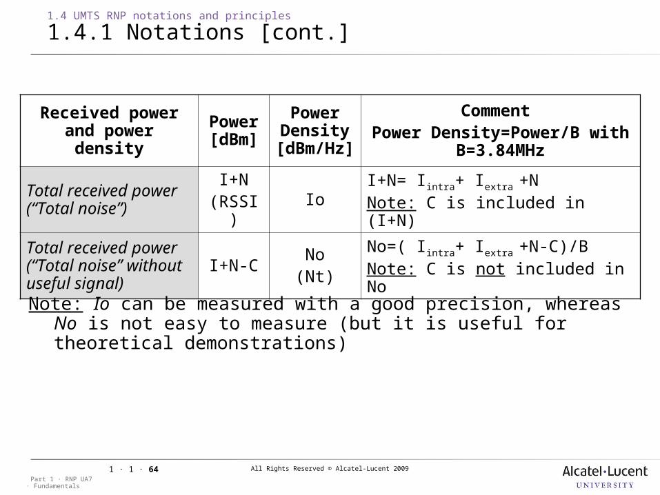
Total received power (“Total noise”)
I+N(RSSI)
IoI+N= Iintra+ Iextra +NNote: C is included in (I+N)
Total received power (“Total noise” without useful signal)
I+N-CNo(Nt)
No=( Iintra+ Iextra +N-C)/BNote: C is not included in No
1.4 UMTS RNP notations and principles
1.4.1 Notations [cont.]
Note: Io can be measured with a good precision, whereas No is not easy to measure (but it is useful for theoretical demonstrations)
All Rights Reserved © Alcatel-Lucent 2009
· FundamentalsPart 1 · RNP UA7
1 · 1 · 65
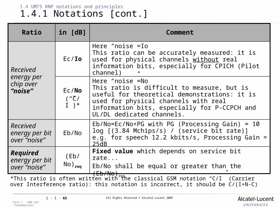
Here “noise”=IoThis ratio can be accurately measured: it is used for physical channels without real information bits, especially for CPICH (Pilot channel)
Ec/Io
Received energy per chip over “noise”
Eb/No=Ec/No+PG with PG (Processing Gain) = 10 log [(3.84 Mchips/s) / (service bit rate)]e.g. for speech 12.2 kbits/s, Processing Gain = 25dB
Eb/No
Received energy per bit over “noise”
Here “noise”=NoThis ratio is difficult to measure, but is useful for theoretical demonstrations: it is used for physical channels with real information bits, especially for P-CCPCH and UL/DL dedicated channels.
Ec/No(“C/I”)*
Fixed value which depends on service bit rate...Eb/No shall be equal or greater than the (Eb/No)req
(Eb/No)req
Required energy per bit over “noise”
Commentin [dB]Ratio
1.4 UMTS RNP notations and principles
1.4.1 Notations [cont.]
*This ratio is often written with the classical GSM notation “C/I” (Carrier over Interference ratio): this notation is incorrect, it should be C/(I+N-C)
All Rights Reserved © Alcatel-Lucent 2009
· FundamentalsPart 1 · RNP UA7
1 · 1 · 66
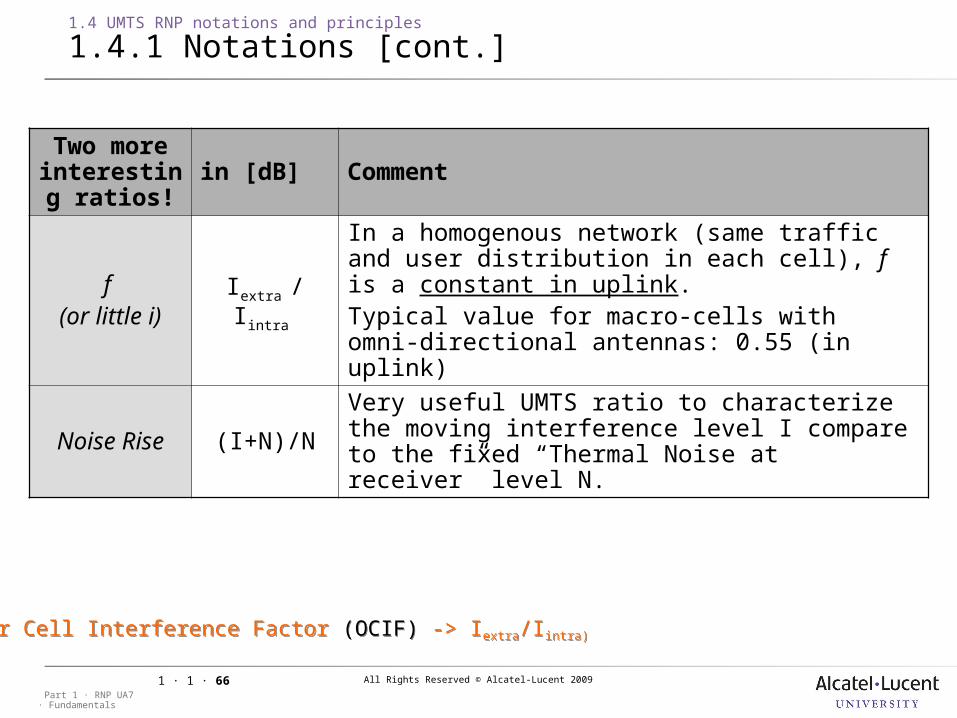
Two more interesting ratios!
in [dB] Comment
f (or little i)
Iextra / Iintra
In a homogenous network (same traffic and user distribution in each cell), f is a constant in uplink. Typical value for macro-cells with omni-directional antennas: 0.55 (in uplink)
Noise Rise (I+N)/NVery useful UMTS ratio to characterize the moving interference level I compare to the fixed “Thermal Noise at receiver” level N.
1.4 UMTS RNP notations and principles
1.4.1 Notations [cont.]
(Other Cell Interference Factor (OCIF) -> Iextra/Iintra)(Other Cell Interference Factor (OCIF) -> Iextra/Iintra)
All Rights Reserved © Alcatel-Lucent 2009
· FundamentalsPart 1 · RNP UA7
1 · 1 · 67
1.4 UMTS RNP notations and principles
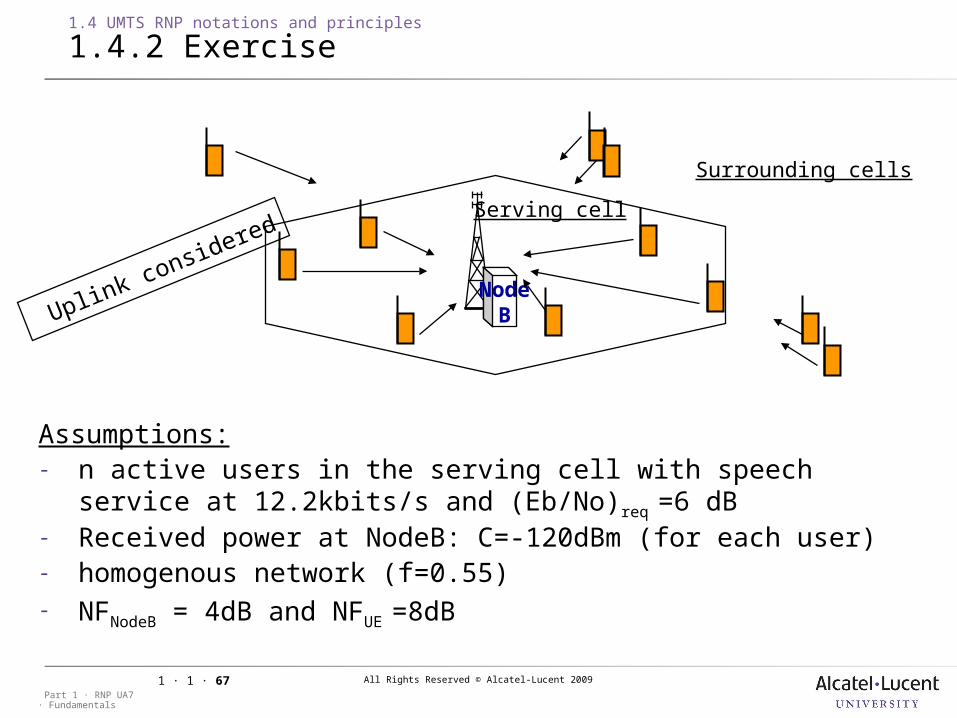
1.4.2 Exercise
Assumptions:- n active users in the serving cell with speech service at
12.2kbits/s and (Eb/No)req =6 dB- Received power at NodeB: C=-120dBm (for each user)- homogenous network (f=0.55)- NFNodeB = 4dB and NFUE =8dB
NodeB
Serving cell
Surrounding cells
Uplink considered
All Rights Reserved © Alcatel-Lucent 2009
· FundamentalsPart 1 · RNP UA7
1 · 1 · 68
1.4 UMTS RNP notations and principles
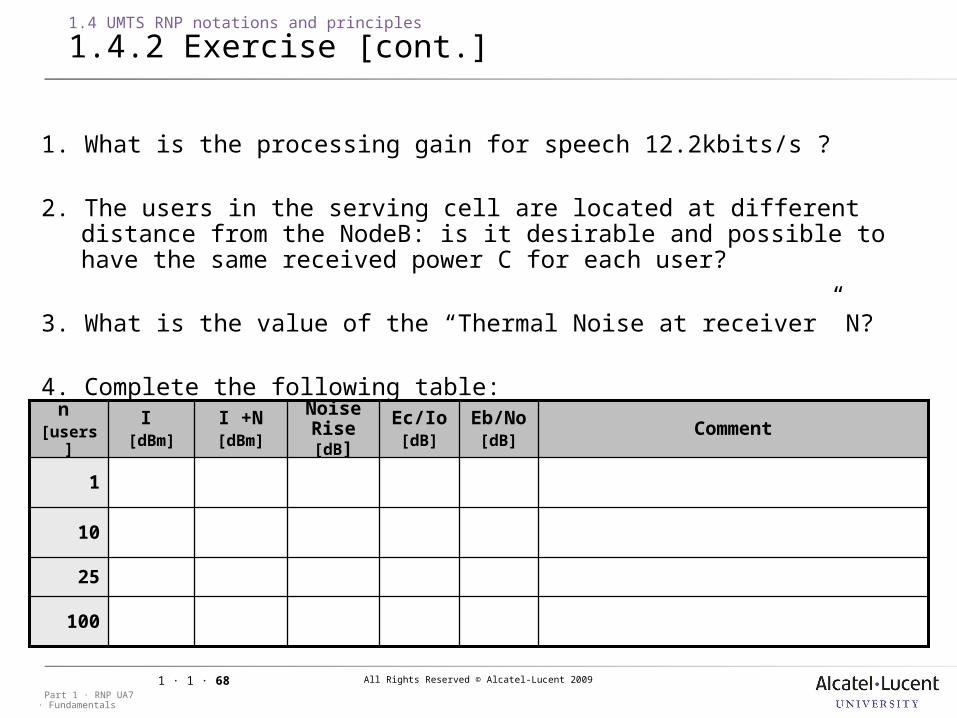
1.4.2 Exercise [cont.]
1. What is the processing gain for speech 12.2kbits/s ?
2. The users in the serving cell are located at different distance from the NodeB: is it desirable and possible to have the same received power C for each user?
3. What is the value of the “Thermal Noise at receiver” N?
4. Complete the following table:
100
I +N[dBm]
25
10
1
CommentEb/No [dB]
Ec/Io [dB]
Noise Rise [dB]
I [dBm]
n [users
]
All Rights Reserved © Alcatel-Lucent 2009
· FundamentalsPart 1 · RNP UA7
1 · 1 · 69
1 UMTS Introduction
1.5 UMTS RNP tool overview
Objective: to be able to describe briefly the structure of a RNP tool
All Rights Reserved © Alcatel-Lucent 2009
· FundamentalsPart 1 · RNP UA7
1 · 1 · 70
1.5 UMTS RNP tool overview
1.5.1 RNP tool requirements
Digital maps topographic data (terrain height)
Resolution: typically 20m for city areas and 50 m for rural areas possibly building and road databases for more accuracy
Coordinates system important for interfacing with measurement tools e.g. UTM based on WGS-84 ellipsoid
morphographic data (clutter type) Resolution: same as topographic data
Propagation model dialog e.g. setting Cost-Hata propagation model parameters
Site/sector/cell/antenna dialog importing sites (e.g GSM sites) setting site/sector/cell/antenna parameters (“Network design
parameters”)Note: in UMTS, sector and cell are not equivalent

All Rights Reserved © Alcatel-Lucent 2009
· FundamentalsPart 1 · RNP UA7
1 · 1 · 71
1.5 UMTS RNP tool overview
1.5.1 RNP tool requirements [cont.]
Link loss calculation Traffic simulation Setting traffic parameters Traffic map generation Resolution: same as topographic data
UE list generation (a snapshot of the UMTS network) Coverage predictions displaying the results on the map showing the results as numerical tables
Automatic neighborhood planning Automatic scrambling code planning Interworking with other tools (dimensioning tools, OMC-UR,
measurements tools, transmission planning tool...)
All Rights Reserved © Alcatel-Lucent 2009
· FundamentalsPart 1 · RNP UA7
1 · 1 · 72
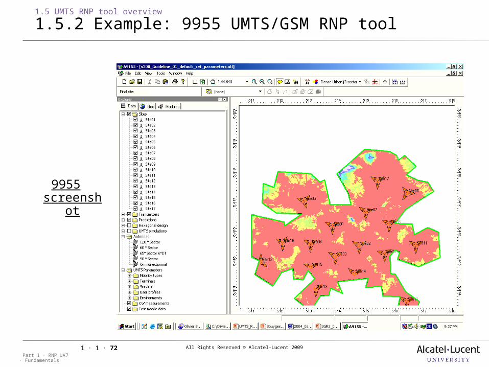
1.5 UMTS RNP tool overview
1.5.2 Example: 9955 UMTS/GSM RNP tool
9955 screensh
ot

All Rights Reserved © Alcatel-Lucent 2009
· FundamentalsPart 1 · RNP UA7
1 · 1 · 73
1.5 UMTS RNP tool overview
1.5.3 High-level ACCO overview
Fully integrated with 9955 Performs the tasks that are tedious & time
consuming to perform Site selection Site placement Antenna tilt & azimuth optimisation Radio feature selection
Allows a large RNP to be performed in substantially less time with greater consistency and repeatability
Broken into two modules: ACCO Greenfield Primarily for site placement but also for site selection, tilt azimuth
optimisation and radio features selection Doesn’t consider interference
ACCO Optimisation Does everything except new site placement
Selected as the official ACP tool for
Alcatel-Lucent
All Rights Reserved © Alcatel-Lucent 2009
· FundamentalsPart 1 · RNP UA7
1 · 1 · 74
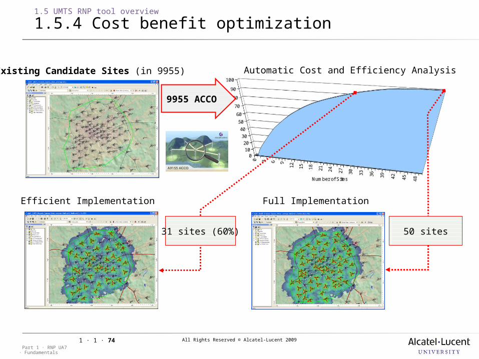
1.5 UMTS RNP tool overview
1.5.4 Cost benefit optimization
9955 ACCO
Automatic Cost and Efficiency Analysis
Efficient Implementation
31 sites (60%) 50 sites
Existing Candidate Sites (in 9955)
Full Implementation
All Rights Reserved © Alcatel-Lucent 2009
· FundamentalsPart 1 · RNP UA7
1 · 1 · 75
Case 1
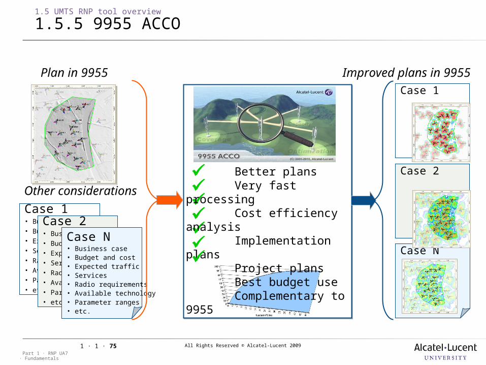
1.5 UMTS RNP tool overview
1.5.5 9955 ACCO
Plan in 9955 Improved plans in 9955
Better plansVery fast
processingCost efficiency
analysisImplementation
plansProject plansBest budget useComplementary to
9955
Other considerations
Case 1• Business case• Budget and cost• Expected traffic• Services • Radio requirements• Available technology• Parameter ranges• etc.
Case 2• Business case• Budget and cost• Expected traffic• Services • Radio requirements• Available technology• Parameter ranges• etc.
Case N• Business case• Budget and cost• Expected traffic• Services • Radio requirements• Available technology• Parameter ranges• etc.
Case N
Case 2
All Rights Reserved © Alcatel-Lucent 2009
· FundamentalsPart 1 · RNP UA7
1 · 1 · 76
1 UMTS Introduction
1.6 RNP process overview
Objective: to be able to briefly describe the RNP Process.
All Rights Reserved © Alcatel-Lucent 2009
· FundamentalsPart 1 · RNP UA7
1 · 1 · 77
1.6 RNP process overview
1.6.1 WCDMA RNP process
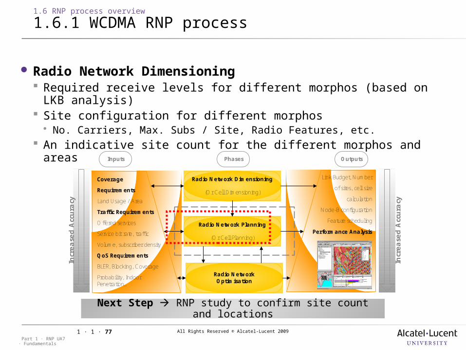
Radio Network Dimensioning Required receive levels for different morphos (based on LKB analysis) Site configuration for different morphos No. Carriers, Max. Subs / Site, Radio Features, etc.
An indicative site count for the different morphos and areas
Next Step RNP study to confirm site count and locations
Radio NetworkOptimisation
Radio Network Planning
(Or Cell Planning)
Radio Network Dimensioning
(Or Cell Dimensioning)
PhasesInputs Outputs
Coverage
Requirements
Land Usage / Area
Traffic Requirements
Offered services
Service bit rate, traffic
Volume, subscriber density
QoS Requirements
BLER, Blocking, Coverage
Probability, Indoor Penetration…
Link Budget, Number
of sites, cell size
calculation
Node-B configuration
Feature scheduling
Performance Analysis
Incr
ease
d A
ccura
cy
Incr
ease
d A
ccura
cy
All Rights Reserved © Alcatel-Lucent 2009
· FundamentalsPart 1 · RNP UA7
1 · 1 · 78
1.6 RNP process overview
1.6.2 Overview
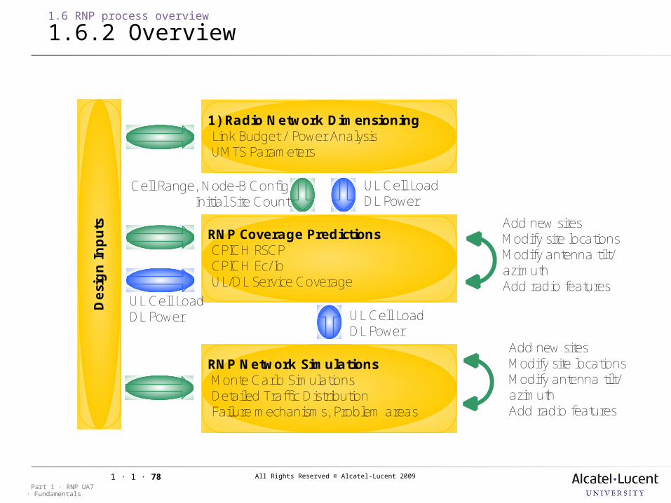
1) Radio Network Dimensioning Link Budget / Power Analysis UMTS Parameters
RNP Coverage Predictions CPICH RSCP CPICH Ec/Io UL/DL Service Coverage
RNP Network Simulations Monte Carlo Simulations Detailed Traffic Distribution Failure mechanisms, Problem areas
Desi
gn Inputs Add new sites
Modify site locationsModify antenna tilt/azimuthAdd radio features
Add new sitesModify site locationsModify antenna tilt/azimuthAdd radio features
UL Cell LoadDL Power
UL Cell LoadDL Power
Cell Range, Node-B ConfigInitial Site Count
UL Cell LoadDL Power
All Rights Reserved © Alcatel-Lucent 2009
· FundamentalsPart 1 · RNP UA7
1 · 1 · 79
1.6 RNP process overview
1.6.3 Inputs required
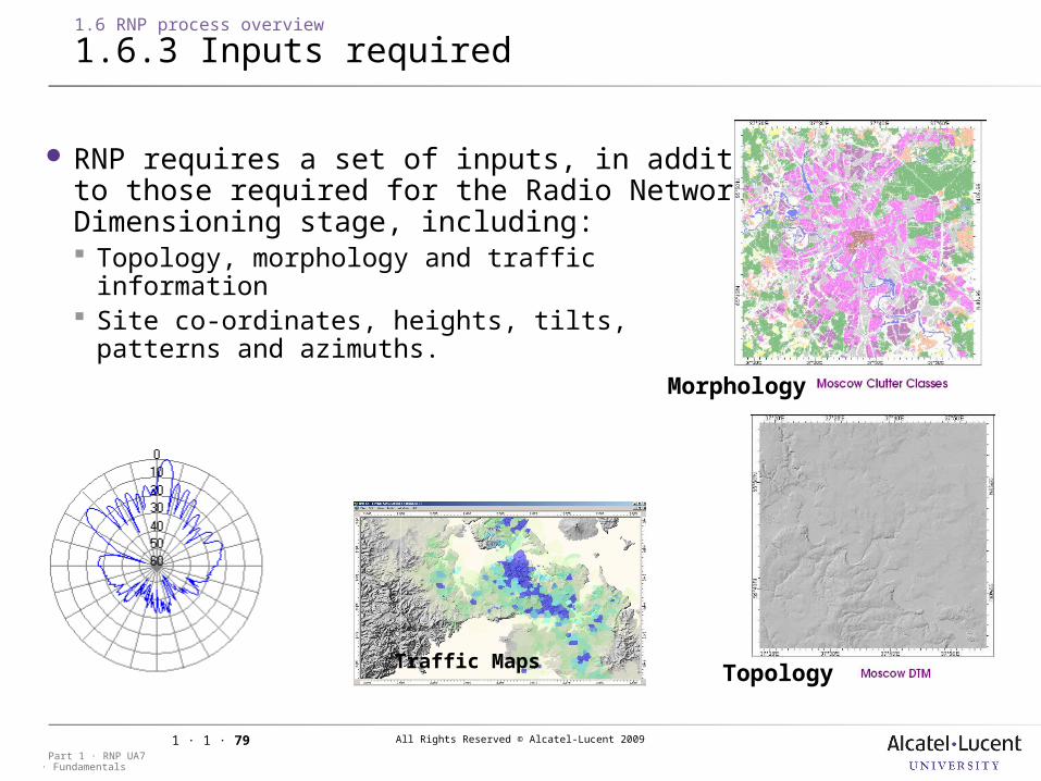
RNP requires a set of inputs, in additionto those required for the Radio NetworkDimensioning stage, including: Topology, morphology and traffic
information Site co-ordinates, heights, tilts,
patterns and azimuths.
Traffic Maps
•Morphology
•Topology
All Rights Reserved © Alcatel-Lucent 2009
· FundamentalsPart 1 · RNP UA7
1 · 1 · 80
1.6 RNP process overview
1.6.4 RNP coverage predictions
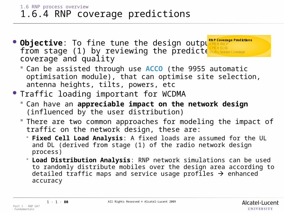
Objective: To fine tune the design outputsfrom stage (1) by reviewing the predictedcoverage and quality Can be assisted through use ACCO (the 9955 automatic optimisation
module), that can optimise site selection, antenna heights, tilts, powers, etc
Traffic loading important for WCDMA Can have an appreciable impact on the network design
(influenced by the user distribution) There are two common approaches for modeling the impact of traffic
on the network design, these are: Fixed Cell Load Analysis: A fixed loads are assumed for the UL and DL
(derived from stage (1) of the radio network design process) Load Distribution Analysis: RNP network simulations can be used to
randomly distribute mobiles over the design area according to detailed traffic maps and service usage profiles enhanced accuracy
RNP Coverage Predictions CPICH RSCP CPICH Ec/Io UL/DL Service Coverage
All Rights Reserved © Alcatel-Lucent 2009
· FundamentalsPart 1 · RNP UA7
1 · 1 · 81
1.6 RNP process overview
1.6.4 RNP coverage predictions [cont.]
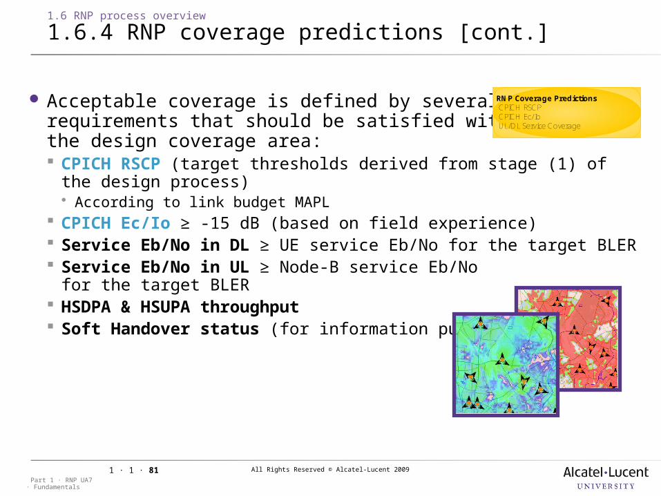
Acceptable coverage is defined by severalrequirements that should be satisfied withinthe design coverage area: CPICH RSCP (target thresholds derived from stage (1) of the design
process) According to link budget MAPL
CPICH Ec/Io ≥ -15 dB (based on field experience) Service Eb/No in DL ≥ UE service Eb/No for the target BLER Service Eb/No in UL ≥ Node-B service Eb/No
for the target BLER HSDPA & HSUPA throughput Soft Handover status (for information purposes)
RNP Coverage Predictions CPICH RSCP CPICH Ec/Io UL/DL Service Coverage
All Rights Reserved © Alcatel-Lucent 2009
· FundamentalsPart 1 · RNP UA7
1 · 1 · 82
1.6 RNP process overview
1.6.5 RNP network simulations
Objective: To account for: The dynamic nature of the interactions between
users (through iterative power control simulations) and the typically non-uniform distribution of the traffic between
sites (defined by the traffic map) Uniform loading assumptions implicit with simple predictions studies
Two common types of RNP network simulation studies that are performed: Load Distribution Simulation Studies – for estimating the UL and
DL loading on a per cell basis (to facilitate enhanced predictions studies)
Detailed Simulation Studies – to assess the network performance in a more rigorous manner in terms of call failures, hotspot analysis, radio feature evolution, rollout analysis
RNP Network Simulations Monte Carlo Simulations Detailed Traffic Distribution Failure mechanisms, Problem areas
All Rights Reserved © Alcatel-Lucent 2009
· FundamentalsPart 1 · RNP UA7
1 · 1 · 83
1.6 RNP process overview
1.6.6 Key ND RNP steps
Typical requirements as part of an RNP study include the following types of studies: Pilot RSCP coverage predictions (always)
Pilot Ec/Io quality predictions (almost always)
Effective Service Area predictions (sometimes)
HSDPA predictions (increasingly common)
HSUPA predictions (imminent requirement)
Simulations (rarely required)
All Rights Reserved © Alcatel-Lucent 2009
· FundamentalsPart 1 · RNP UA7
1 · 1 · 84
2 Inputs for Radio Network Planning
All Rights Reserved © Alcatel-Lucent 2009
· FundamentalsPart 1 · RNP UA7
1 · 1 · 85
2 Inputs for Radio Network Planning
2.1 Session presentation
Objective to be able to describe the UMTS RNP inputs with regard
to frequency spectrum, traffic parameters, equipment parameters and radio network requirements.

All Rights Reserved © Alcatel-Lucent 2009
· FundamentalsPart 1 · RNP UA7
1 · 1 · 86
2.1 Session presentation
2.1.1 UMTS FDD frequency spectrum
Objective:
to be able to describe the UMTS FDD frequency parameters defined by the 3GPP
All Rights Reserved © Alcatel-Lucent 2009
· FundamentalsPart 1 · RNP UA7
1 · 1 · 87
2.1.1 UMTS FDD frequency spectrum
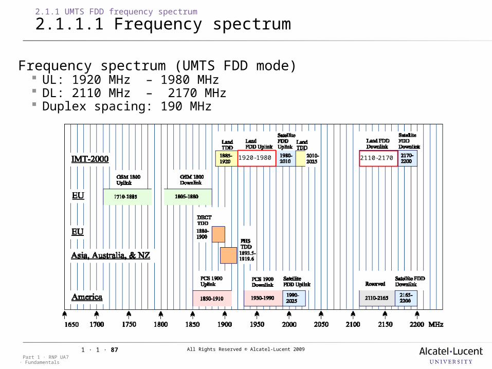
2.1.1.1 Frequency spectrum
1920-1980 2110-2170
Frequency spectrum (UMTS FDD mode) UL: 1920 MHz – 1980 MHz DL: 2110 MHz – 2170 MHz Duplex spacing: 190 MHz
All Rights Reserved © Alcatel-Lucent 2009
· FundamentalsPart 1 · RNP UA7
1 · 1 · 88
2.1.1 UMTS FDD frequency spectrum
2.1.1.2 Carrier spacing
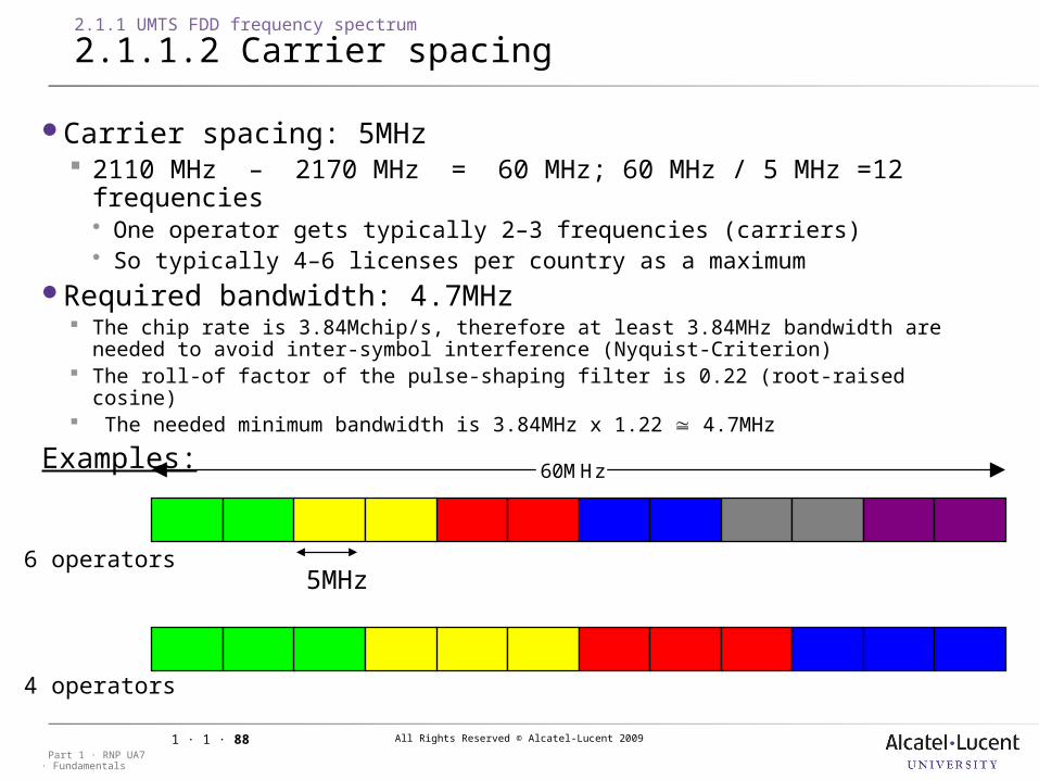
Carrier spacing: 5MHz 2110 MHz – 2170 MHz = 60 MHz; 60 MHz / 5 MHz =12 frequencies One operator gets typically 2–3 frequencies (carriers) So typically 4–6 licenses per country as a maximum
Required bandwidth: 4.7MHz The chip rate is 3.84Mchip/s, therefore at least 3.84MHz bandwidth are needed to avoid
inter-symbol interference (Nyquist-Criterion) The roll-of factor of the pulse-shaping filter is 0.22 (root-raised cosine) The needed minimum bandwidth is 3.84MHz x 1.22 4.7MHz
Examples:
60MHz
5MHz6 operators
4 operators
All Rights Reserved © Alcatel-Lucent 2009
· FundamentalsPart 1 · RNP UA7
1 · 1 · 89
2.1.1 UMTS FDD frequency spectrum
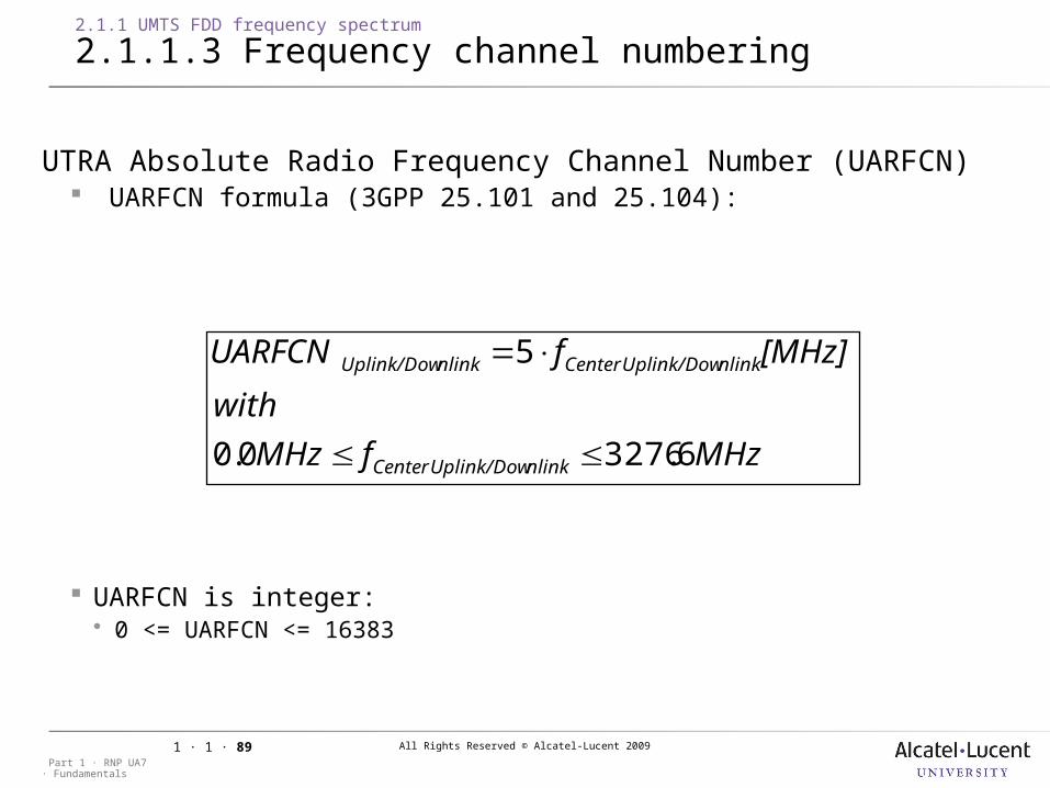
2.1.1.3 Frequency channel numbering
UTRA Absolute Radio Frequency Channel Number (UARFCN) UARFCN formula (3GPP 25.101 and 25.104):
MHz.fMHz
with
[MHz]fUARFCN
nlinkUplink/DowCenter
nlinkUplink/DowCenternlinkUplink/Dow
632760.0
5
UARFCN is integer: 0 <= UARFCN <= 16383
All Rights Reserved © Alcatel-Lucent 2009
· FundamentalsPart 1 · RNP UA7
1 · 1 · 90
2.1.1 UMTS FDD frequency spectrum
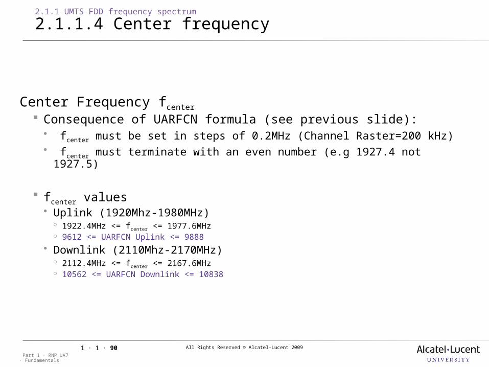
2.1.1.4 Center frequency
Center Frequency fcenter
Consequence of UARFCN formula (see previous slide): fcenter must be set in steps of 0.2MHz (Channel Raster=200 kHz) fcenter must terminate with an even number (e.g 1927.4 not 1927.5)
fcenter values Uplink (1920Mhz-1980MHz)
1922.4MHz <= fcenter <= 1977.6MHz 9612 <= UARFCN Uplink <= 9888
Downlink (2110Mhz-2170MHz) 2112.4MHz <= fcenter <= 2167.6MHz 10562 <= UARFCN Downlink <= 10838
All Rights Reserved © Alcatel-Lucent 2009
· FundamentalsPart 1 · RNP UA7
1 · 1 · 91
2.1.1 UMTS FDD frequency spectrum
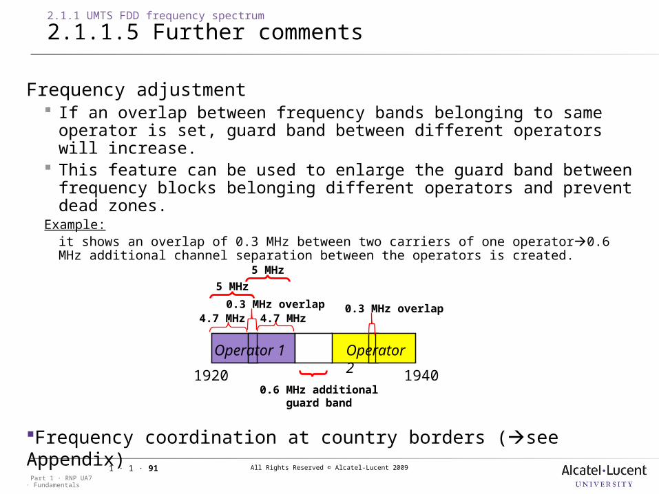
2.1.1.5 Further comments
Frequency adjustment If an overlap between frequency bands belonging to same operator
is set, guard band between different operators will increase. This feature can be used to enlarge the guard band between
frequency blocks belonging different operators and prevent dead zones.
Example:it shows an overlap of 0.3 MHz between two carriers of one operator0.6 MHz additional channel separation between the operators is created.
0.6 MHz additionalguard band
5 MHz
5 MHz
4.7 MHz 4.7 MHz0.3 MHz overlap
1920 1940
Operator 1 Operator 2
Frequency coordination at country borders (see Appendix)
0.3 MHz overlap
All Rights Reserved © Alcatel-Lucent 2009
· FundamentalsPart 1 · RNP UA7
1 · 1 · 92
2.1 Session presentation
2.1.2 UMTS traffic parameters (UMTS traffic map)
Objective: to be able to describe the method to create a traffic map
All Rights Reserved © Alcatel-Lucent 2009
· FundamentalsPart 1 · RNP UA7
1 · 1 · 93
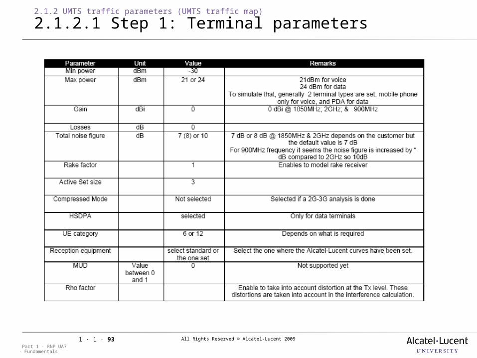
2.1.2 UMTS traffic parameters (UMTS traffic map)
2.1.2.1 Step 1: Terminal parameters
All Rights Reserved © Alcatel-Lucent 2009
· FundamentalsPart 1 · RNP UA7
1 · 1 · 94
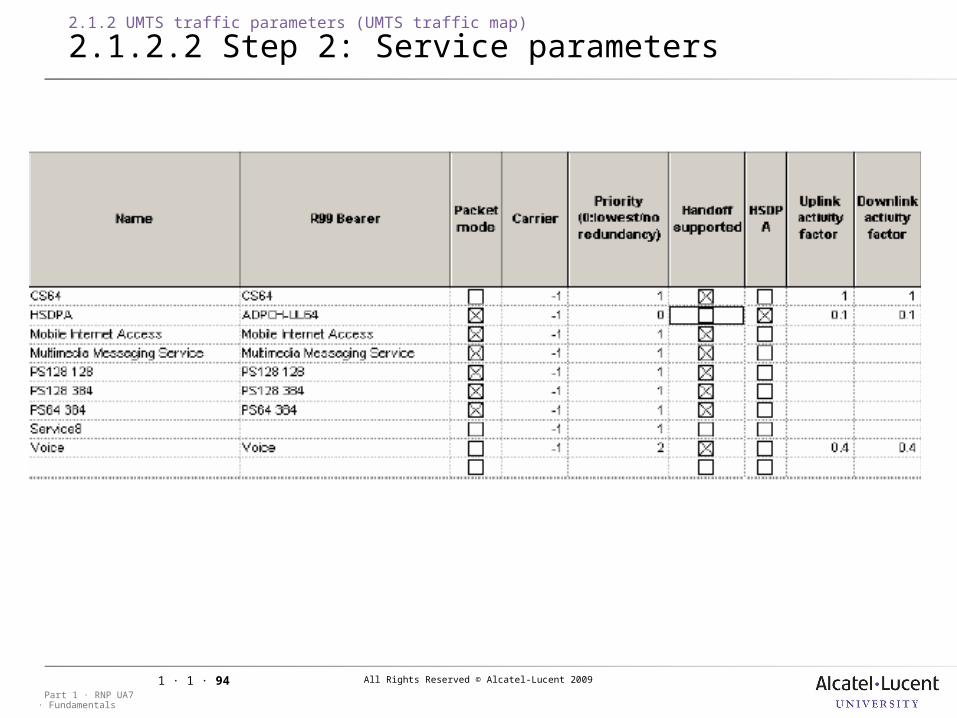
2.1.2 UMTS traffic parameters (UMTS traffic map)
2.1.2.2 Step 2: Service parameters
All Rights Reserved © Alcatel-Lucent 2009
· FundamentalsPart 1 · RNP UA7
1 · 1 · 95
2.1.2 UMTS traffic parameters (UMTS traffic map)
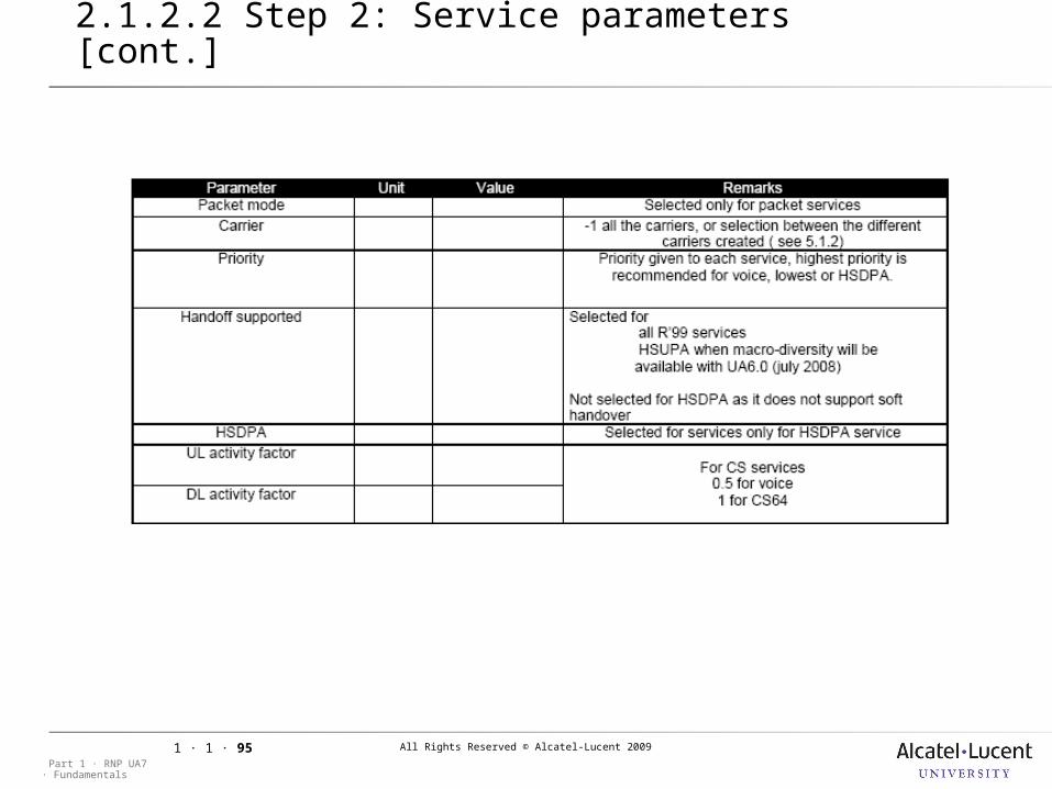
2.1.2.2 Step 2: Service parameters [cont.]
All Rights Reserved © Alcatel-Lucent 2009
· FundamentalsPart 1 · RNP UA7
1 · 1 · 96
2.1.2 UMTS traffic parameters (UMTS traffic map)
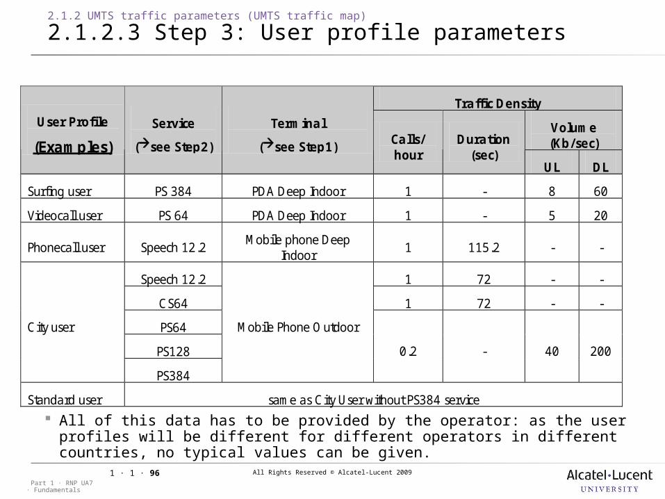
2.1.2.3 Step 3: User profile parameters
Traffic Density
Volume (Kb/sec)
User Profile
(Examples)
Service
(see Step2)
Terminal
(see Step1) Calls/ hour
Duration (sec)
UL DL
Surfing user PS 384 PDA Deep Indoor 1 - 8 60
Videocall user PS 64 PDA Deep Indoor 1 - 5 20
Phonecall user Speech 12.2 Mobile phone Deep
Indoor 1 115.2 - -
Speech 12.2 1 72 - -
CS64 1 72 - -
PS64
PS128
City user
PS384
Mobile Phone Outdoor
0.2 - 40 200
Standard user same as City User without PS384 service
All of this data has to be provided by the operator: as the user profiles will be different for different operators in different countries, no typical values can be given.
All Rights Reserved © Alcatel-Lucent 2009
· FundamentalsPart 1 · RNP UA7
1 · 1 · 97
2.1.2 UMTS traffic parameters (UMTS traffic map)
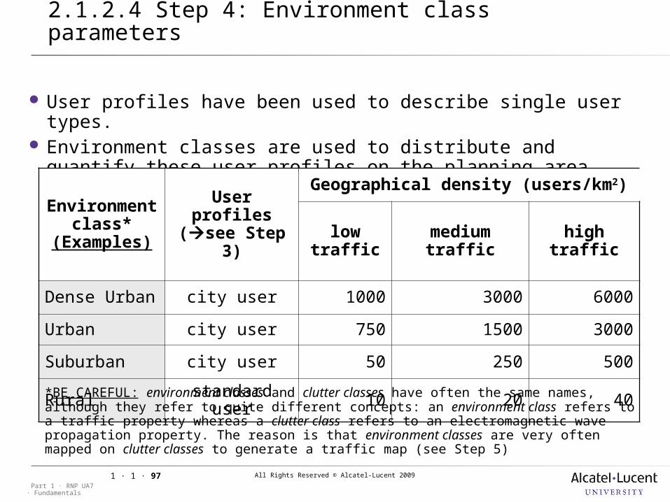
2.1.2.4 Step 4: Environment class parameters
User profiles have been used to describe single user types. Environment classes are used to distribute and quantify these
user profiles on the planning area.
Environment class*
(Examples)
User profiles (see Step
3)
Geographical density (users/km2)
low traffic
medium traffic
high traffic
Dense Urban city user 1000 3000 6000
Urban city user 750 1500 3000
Suburban city user 50 250 500
Rural standard user 10 20 40
*BE CAREFUL: environment classes and clutter classes have often the same names, although they refer to quite different concepts: an environment class refers to a traffic property whereas a clutter class refers to an electromagnetic wave propagation property. The reason is that environment classes are very often mapped on clutter classes to generate a traffic map (see Step 5)
All Rights Reserved © Alcatel-Lucent 2009
· FundamentalsPart 1 · RNP UA7
1 · 1 · 98
2.1.2 UMTS traffic parameters (UMTS traffic map)
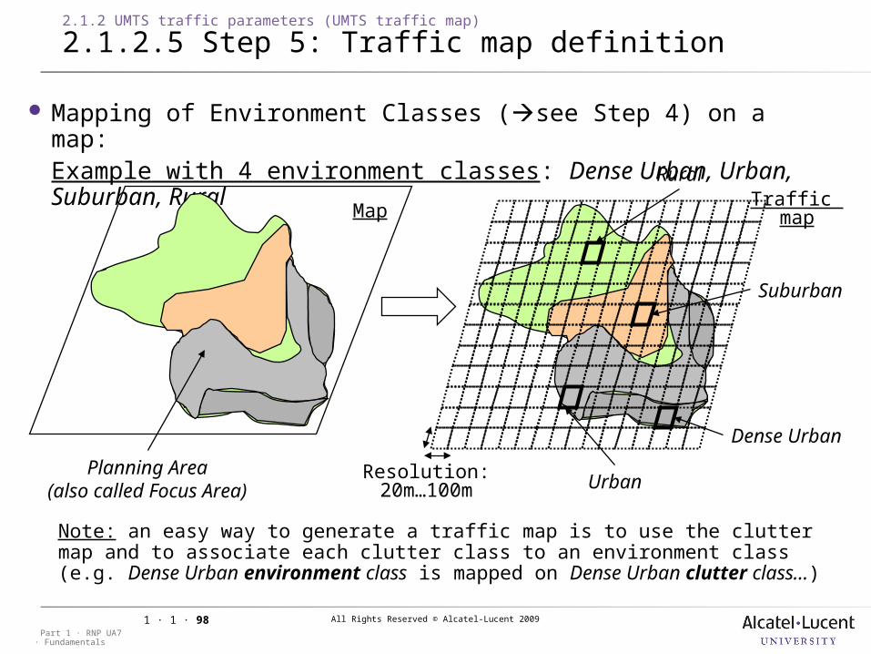
2.1.2.5 Step 5: Traffic map definition
Mapping of Environment Classes (see Step 4) on a map: Example with 4 environment classes: Dense Urban, Urban, Suburban, Rural
Dense Urban
Urban
Rural
Suburban
Resolution:20m…100m
Planning Area(also called Focus
Area)
MapTraffic map
Note: an easy way to generate a traffic map is to use the clutter map and to associate each clutter class to an environment class (e.g. Dense Urban environment class is mapped on Dense Urban clutter class…)
All Rights Reserved © Alcatel-Lucent 2009
· FundamentalsPart 1 · RNP UA7
1 · 1 · 99
2.1 Session presentation
2.1.3 UMTS terminal, NodeB and antenna overview
Objective: to be able to describe briefly the main characteristics of the UMTS
radio equipment (UE, NodeB and antenna)
All Rights Reserved © Alcatel-Lucent 2009
· FundamentalsPart 1 · RNP UA7
1 · 1 · 100
2.1.3 UMTS terminal, NodeB and antenna overview
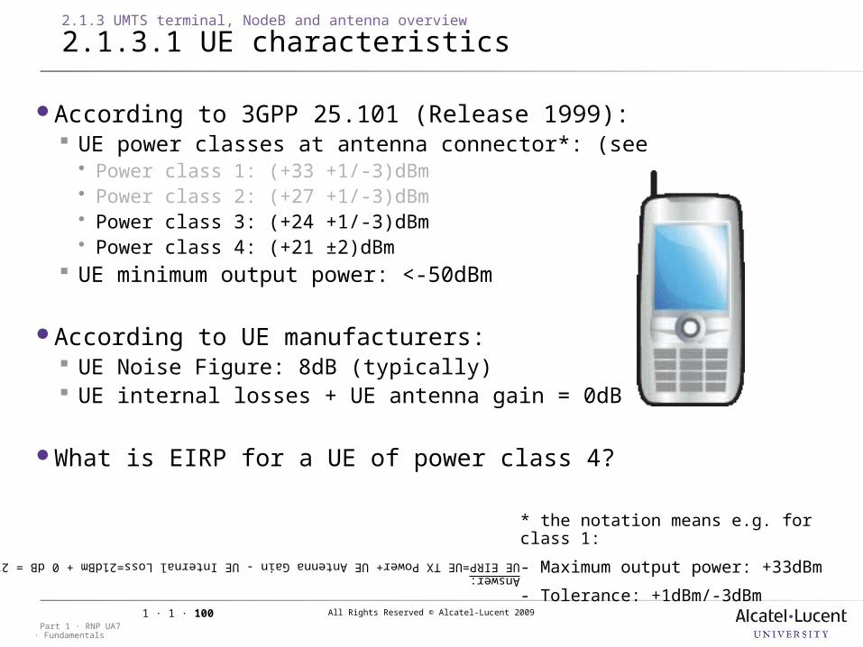
2.1.3.1 UE characteristics
According to 3GPP 25.101 (Release 1999): UE power classes at antenna connector*: (see Power class 1: (+33 +1/-3)dBm Power class 2: (+27 +1/-3)dBm Power class 3: (+24 +1/-3)dBm Power class 4: (+21 ±2)dBm
UE minimum output power: <-50dBm
According to UE manufacturers: UE Noise Figure: 8dB (typically) UE internal losses + UE antenna gain = 0dB
What is EIRP for a UE of power class 4?
* the notation means e.g. for class 1:
- Maximum output power: +33dBm
- Tolerance: +1dBm/-3dBm
Answer: UE EIRP=UE TX Power+ UE Antenna Gain - UE Internal Loss=21dBm + 0 dB = 21 dBm
All Rights Reserved © Alcatel-Lucent 2009
· FundamentalsPart 1 · RNP UA7
1 · 1 · 101
2.1.3 UMTS terminal, NodeB and antenna overview
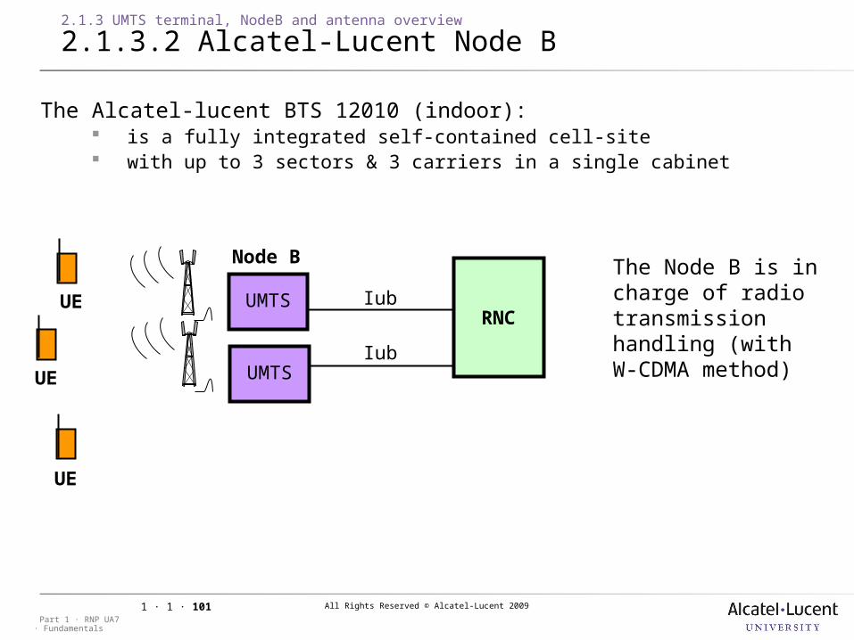
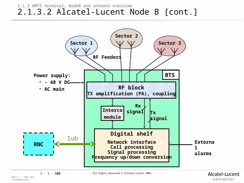
2.1.3.2 Alcatel-Lucent Node B
The Alcatel-lucent BTS 12010 (indoor): is a fully integrated self-contained cell-site with up to 3 sectors & 3 carriers in a single cabinet
Iub
Node B
RNC
UE
UE
UE UMTS
Iub
The Node B is in charge of radio transmission handling (with W-CDMA method)UMTS
All Rights Reserved © Alcatel-Lucent 2009
· FundamentalsPart 1 · RNP UA7
1 · 1 · 102
2.1.3 UMTS terminal, NodeB and antenna overview
2.1.3.2 Alcatel-Lucent Node B [cont.]
Sector 2
RF blockTX amplification (PA), coupling
Sector 1 Sector 3
Digital shelf
Network interfaceCall processing
Signal processingFrequency up/down conversion
RNC
Interco
moduleTx signal
Rx signal
IubExternal alarms
RF Feeders
BTSPower supply:• - 48 V DC• AC main
All Rights Reserved © Alcatel-Lucent 2009
· FundamentalsPart 1 · RNP UA7
1 · 1 · 103
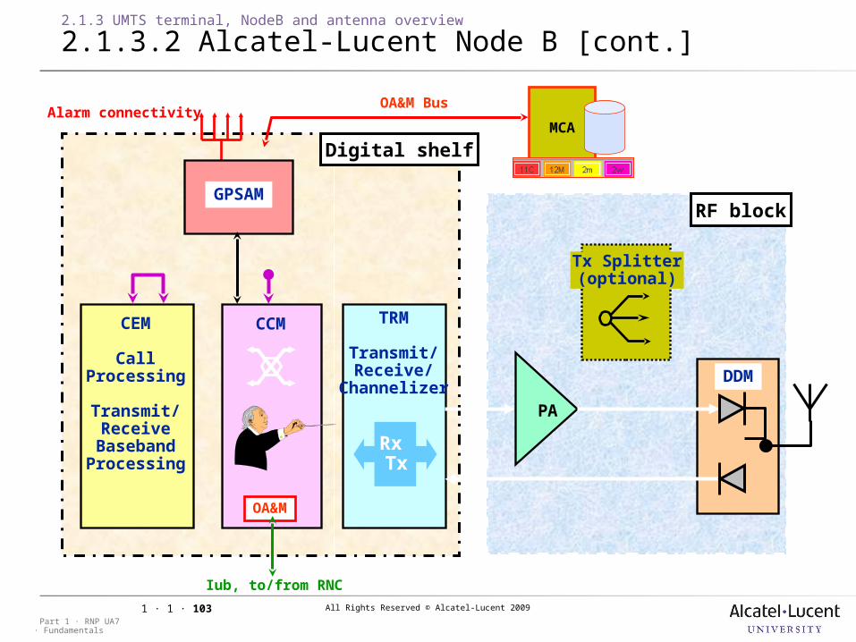
Digital shelf
CCMCCM
Alarm connectivity
CEM
CallProcessing
Transmit/Receive
BasebandProcessing
TRM
Transmit/Receive/
Channelizer
Rx Tx
GPSAM
OA&M
CCM
RF block
Tx Splitter(optional)
DDM
MCA
PA
Iub, to/from RNC
OA&M Bus
2.1.3 UMTS terminal, NodeB and antenna overview
2.1.3.2 Alcatel-Lucent Node B [cont.]
All Rights Reserved © Alcatel-Lucent 2009
· FundamentalsPart 1 · RNP UA7
1 · 1 · 104
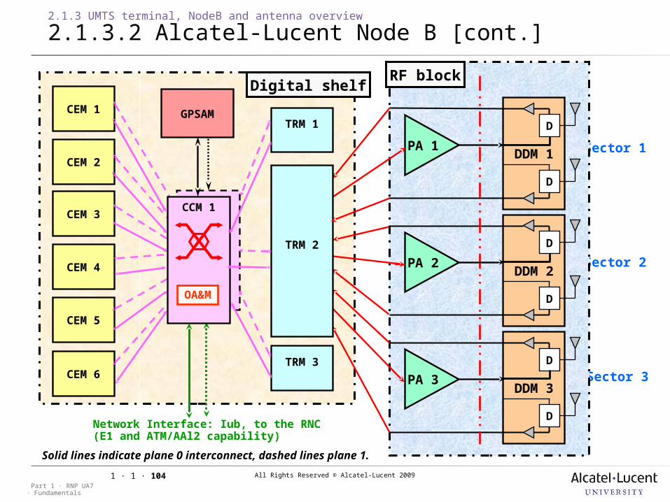
2.1.3 UMTS terminal, NodeB and antenna overview
2.1.3.2 Alcatel-Lucent Node B [cont.]
MCPA
MCPA
MCPA Sector 1
Sector 2
Sector 3
CEM 3
CEM 2
CEM 1 GPSAM
Digital shelf
Network Interface: Iub, to the RNC(E1 and ATM/AAl2 capability)
Solid lines indicate plane 0 interconnect, dashed lines plane 1.
TRM 1
DDM 1
D
D
PA 1
DDM 2
D
D
DDM 3
D
D
PA 2
PA 3
CEM 4
TRM 2
TRM 3
RF block
CEM 5
CEM 6
CCM 1
OA&M
All Rights Reserved © Alcatel-Lucent 2009
· FundamentalsPart 1 · RNP UA7
1 · 1 · 105
2.1.3 UMTS terminal, NodeB and antenna overview
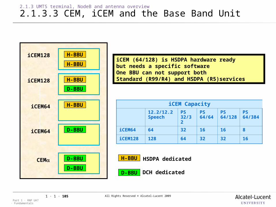
2.1.3.3 CEM, iCEM and the Base Band Unit
iCEM128 H-BBU
H-BBU
H-BBU
D-BBU
H-BBU
D-BBU
D-BBU
D-BBU
iCEM128
iCEM64
iCEM64
CEM
iCEM (64/128) is HSDPA hardware readybut needs a specific softwareOne BBU can not support both Standard (R99/R4) and HSDPA (R5)services
iCEM Capacity
12.2/12.2Speech
PS32/32
PS64/64
PS64/128
PS64/384
iCEM64 64 32 16 16 8
iCEM128 128 64 32 32 16
H-BBU
D-BBU
HSDPA dedicated
DCH dedicated
All Rights Reserved © Alcatel-Lucent 2009
· FundamentalsPart 1 · RNP UA7
1 · 1 · 106
2.1.3 UMTS terminal, NodeB and antenna overview
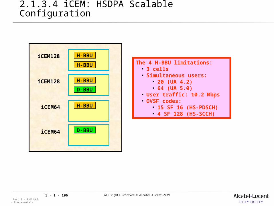
2.1.3.4 iCEM: HSDPA Scalable Configuration
iCEM128 H-BBU
H-BBU
H-BBU
D-BBU
H-BBU
D-BBU
iCEM128
iCEM64
iCEM64
The 4 H-BBU limitations:• 3 cells• Simultaneous users:
• 20 (UA 4.2)• 64 (UA 5.0)
• User traffic: 10.2 Mbps • OVSF codes:
• 15 SF 16 (HS-PDSCH)• 4 SF 128 (HS-SCCH)
All Rights Reserved © Alcatel-Lucent 2009
· FundamentalsPart 1 · RNP UA7
1 · 1 · 107
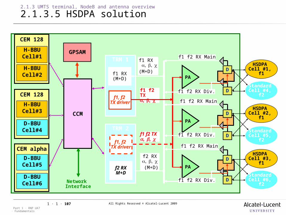
2.1.3 UMTS terminal, NodeB and antenna overview
2.1.3.5 HSDPA solution
f1 f2 TX
f1 f2 TX
f1 RX (M+D)
CEM 128
CEM alpha
Network Interface
CCM
GPSAM
CEM 128
f2 RX (M+D)
D
D
D
D
TRM 1
PA
PA
PA
D
D
f1 f2 RX Main
f1 f2 RX Div.
f1 f2 RX Main
f1 f2 RX Div.
f1 f2 RX Main
f1 f2 RX Div.
f1 RX(M+D)
f1, f2 TX driver
TRM 2
f2 RX(M+D)
f1, f2 TX driver
H-BBUCell#3
D-BBUCell#4
H-BBUCell#1
H-BBUCell#2
D-BBUCell#5
D-BBUCell#6
HSDPA Cell #1,
f1
HSDPA Cell #2,
f1
HSDPA Cell #3,
f1
Standard Cell #4,
f2
Standard Cell #5,
f2
Standard Cell #6,
f2
All Rights Reserved © Alcatel-Lucent 2009
· FundamentalsPart 1 · RNP UA7
1 · 1 · 108
2.1.3 UMTS terminal, NodeB and antenna overview
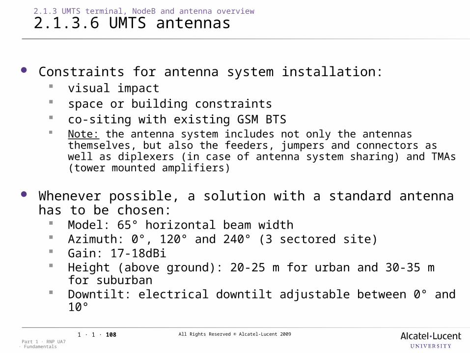
2.1.3.6 UMTS antennas
Constraints for antenna system installation: visual impact space or building constraints co-siting with existing GSM BTS Note: the antenna system includes not only the antennas themselves, but
also the feeders, jumpers and connectors as well as diplexers (in case of antenna system sharing) and TMAs (tower mounted amplifiers)
Whenever possible, a solution with a standard antenna has to be chosen: Model: 65° horizontal beam width Azimuth: 0°, 120° and 240° (3 sectored site) Gain: 17-18dBi Height (above ground): 20-25 m for urban and 30-35 m for
suburban Downtilt: electrical downtilt adjustable between 0° and 10°
All Rights Reserved © Alcatel-Lucent 2009
· FundamentalsPart 1 · RNP UA7
1 · 1 · 109
2.1.3 UMTS terminal, NodeB and antenna overview
2.1.3.6 UMTS antennas [cont.]
Antenna parameters are key parameters which can be tuned to decrease interference in critical zones, especially: Antenna downtilt
increasing the antenna downtilt of an interfering cell can optimize the RF conditions
downtilt changes with a difference less than 2° compared to the previous value do not make sense, since the modification effort (requiring on-site tuning) does not stand in relation to the effect.
rule of thumb: the downtilt in UMTS should be at least 1°-2° higher than the value a planner would choose for GSM
Antenna azimuth by re-directing the beam direction of the interfering cell azimuth modifications of 10°-20° compared to the previous value
do not make sense
Note: Azimuth/downtilt modifications can be restricted or even forbidden due to antenna system installation constraints (especially the constraints for UMTS/GSM co-location)
All Rights Reserved © Alcatel-Lucent 2009
· FundamentalsPart 1 · RNP UA7
1 · 1 · 110
2.1 Session presentation
2.1.4 Radio network requirements
Objective: to be able to understand the parameters, which define the UMTS
radio network requirements in terms of coverage, traffic and quality of service
All Rights Reserved © Alcatel-Lucent 2009
· FundamentalsPart 1 · RNP UA7
1 · 1 · 111
2.1.4 Radio network requirements
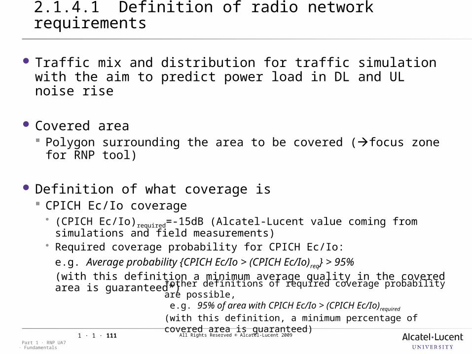
2.1.4.1 Definition of radio network requirements
Traffic mix and distribution for traffic simulation with the aim to predict power load in DL and UL noise rise
Covered area Polygon surrounding the area to be covered (focus zone for RNP
tool)
Definition of what coverage is CPICH Ec/Io coverage (CPICH Ec/Io)required=-15dB (Alcatel-Lucent value coming from simulations
and field measurements) Required coverage probability for CPICH Ec/Io:
e.g. Average probability {CPICH Ec/Io > (CPICH Ec/Io)req} > 95%(with this definition a minimum average quality in the covered area is guaranteed*)
*other definitions of required coverage probability are possible, e.g. 95% of area with CPICH Ec/Io > (CPICH Ec/Io)required
(with this definition, a minimum percentage of covered area is guaranteed)
All Rights Reserved © Alcatel-Lucent 2009
· FundamentalsPart 1 · RNP UA7
1 · 1 · 112
2.1.4 Radio network requirements
2.1.4.1 Definition of radio network requirements [cont.]
UL and DL service coverage (Eb/No)reqspecific value for each service and for each direction (UL/DL), Required coverage probability for DL and UL services:
e.g. Average probability {Eb/No > (Eb/No)req} > 95% (for each direction UL/DL and for each service)Note: It is possible to define different required coverage probabilities for different services.
Eb/No values can not easily be measured, but nevertheless service coverage predictions are a good source of information to improve the radio network design (to find the limiting resources).

All Rights Reserved © Alcatel-Lucent 2009
· FundamentalsPart 1 · RNP UA7
1 · 1 · 113
2.1.4 Radio network requirements
2.1.4.1 Definition of radio network requirements [cont.]
CPICH RSCP coverage (optional) (CPICH RSCP)required: it can be defined, if the maximum allowed path loss is
determined by calculating a link budget and taking into account the CPICH output power (if no traffic mix is available, the link budget would base on the limiting service)
Required coverage probability for CPICH RSCPe.g. Average probability {CPICH RSCP > (CPICH RSCP)req}>95%(To guarantee an average reliability, that the minimum level is fulfilled in the covered area)
CPICH RSCP prediction is not mandatory, but: it can be a help to guarantee a certain level of indoor coverage from outdoor cells,
taking into account different indoor losses for different areas. CPICH RSCP can easily be measured using a 3G scanner.
All Rights Reserved © Alcatel-Lucent 2009
· FundamentalsPart 1 · RNP UA7
1 · 1 · 114
3 WCDMA RNP Predictions
All Rights Reserved © Alcatel-Lucent 2009
· FundamentalsPart 1 · RNP UA7
1 · 1 · 115
3 WCDMA RNP Predictions
3.1 CPICH RSCP predictions
Objective: Validate analytical LKB results by RNPSteps: 1) Determine CPICH RSCP
Thresholds UL harmonised link budget
2) Set Cell Parameters 3) Create Prediction Set Prediction Conditions Set RSCP thresholds
All Rights Reserved © Alcatel-Lucent 2009
· FundamentalsPart 1 · RNP UA7
1 · 1 · 116
3.1 CPICH RSCP predictions
3.1.1 Determine CPICH RSCP thresholds
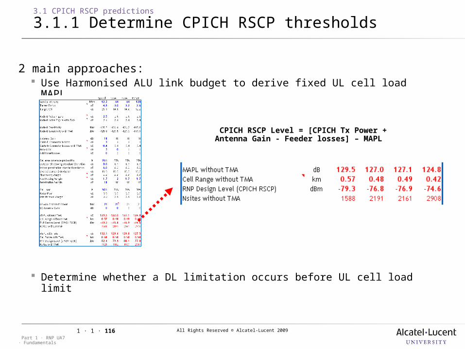
2 main approaches: Use Harmonised ALU link budget to derive fixed UL cell load MAPL
Determine whether a DL limitation occurs before UL cell load limit
•CPICH RSCP Level = [CPICH Tx Power + Antenna Gain - Feeder losses] – MAPL
All Rights Reserved © Alcatel-Lucent 2009
· FundamentalsPart 1 · RNP UA7
1 · 1 · 117
3.1 CPICH RSCP predictions
3.1.2 Set cell parameters
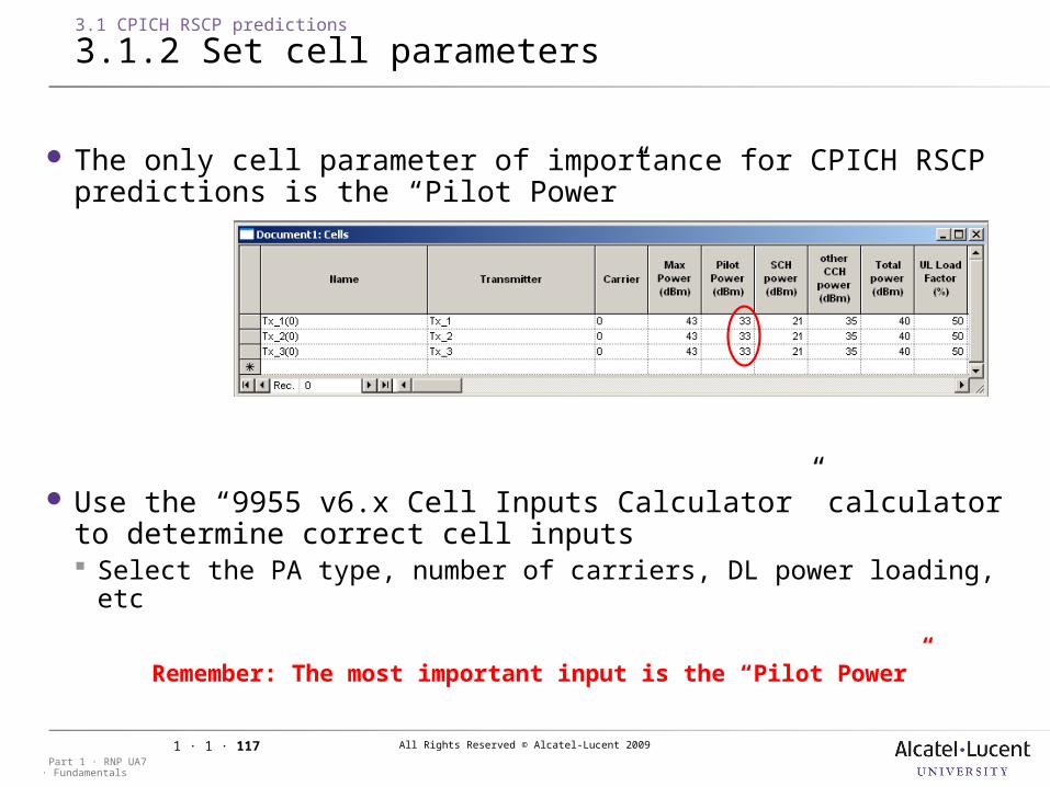
The only cell parameter of importance for CPICH RSCP predictions is the “Pilot Power”
Use the “9955 v6.x Cell Inputs Calculator” calculator to determine correct cell inputs Select the PA type, number of carriers, DL power loading, etc
•Remember: The most important input is the “Pilot Power”
All Rights Reserved © Alcatel-Lucent 2009
· FundamentalsPart 1 · RNP UA7
1 · 1 · 118
3.1 CPICH RSCP predictions
3.1.3 Create prediction
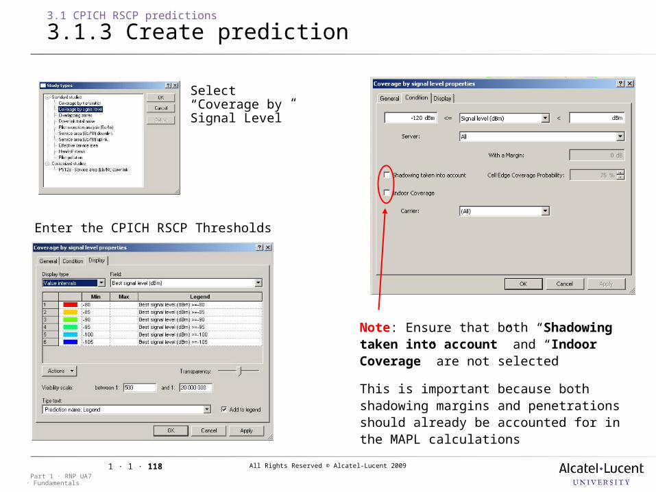
Note: Ensure that both “Shadowing taken into account” and “Indoor Coverage” are not selected
This is important because both shadowing margins and penetrations should already be accounted for in the MAPL calculations
Select “Coverage by Signal Level”
Enter the CPICH RSCP Thresholds
All Rights Reserved © Alcatel-Lucent 2009
· FundamentalsPart 1 · RNP UA7
1 · 1 · 119
3 WCDMA RNP Predictions
3.2 Pilot Ec/Io predictions
Objective: Check the quality of the network by RNPSteps: 1) Set Cell Parameters 2) Define Penetration Margins (optional) 3) Set Terminal Parameters 4) Create Prediction Set Prediction Conditions Set RSCP thresholds
All Rights Reserved © Alcatel-Lucent 2009
· FundamentalsPart 1 · RNP UA7
1 · 1 · 120
3.2 Pilot Ec/Io predictions
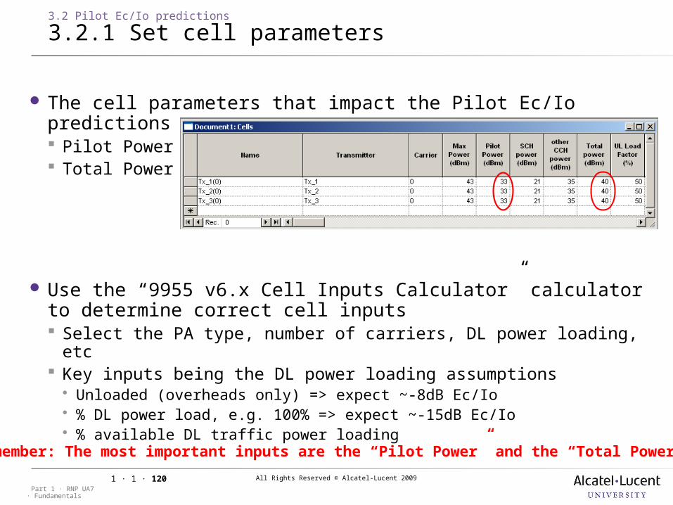
3.2.1 Set cell parameters
The cell parameters that impact the Pilot Ec/Io predictions are: Pilot Power Total Power
Use the “9955 v6.x Cell Inputs Calculator” calculator to determine correct cell inputs Select the PA type, number of carriers, DL power loading, etc Key inputs being the DL power loading assumptions Unloaded (overheads only) => expect ~-8dB Ec/Io % DL power load, e.g. 100% => expect ~-15dB Ec/Io % available DL traffic power loading
•Remember: The most important inputs are the “Pilot Power” and the “Total Power”
All Rights Reserved © Alcatel-Lucent 2009
· FundamentalsPart 1 · RNP UA7
1 · 1 · 121
3.2 Pilot Ec/Io predictions
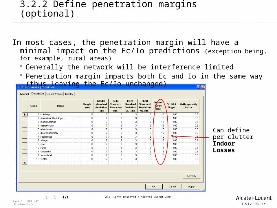
3.2.2 Define penetration margins (optional)
In most cases, the penetration margin will have a minimal impact on the Ec/Io predictions (exception being, for example, rural areas) Generally the network will be interference limited Penetration margin impacts both Ec and Io in the same way (thus
leaving the Ec/Io unchanged)
Can define per clutter Indoor Losses
All Rights Reserved © Alcatel-Lucent 2009
· FundamentalsPart 1 · RNP UA7
1 · 1 · 122
3.2 Pilot Ec/Io predictions
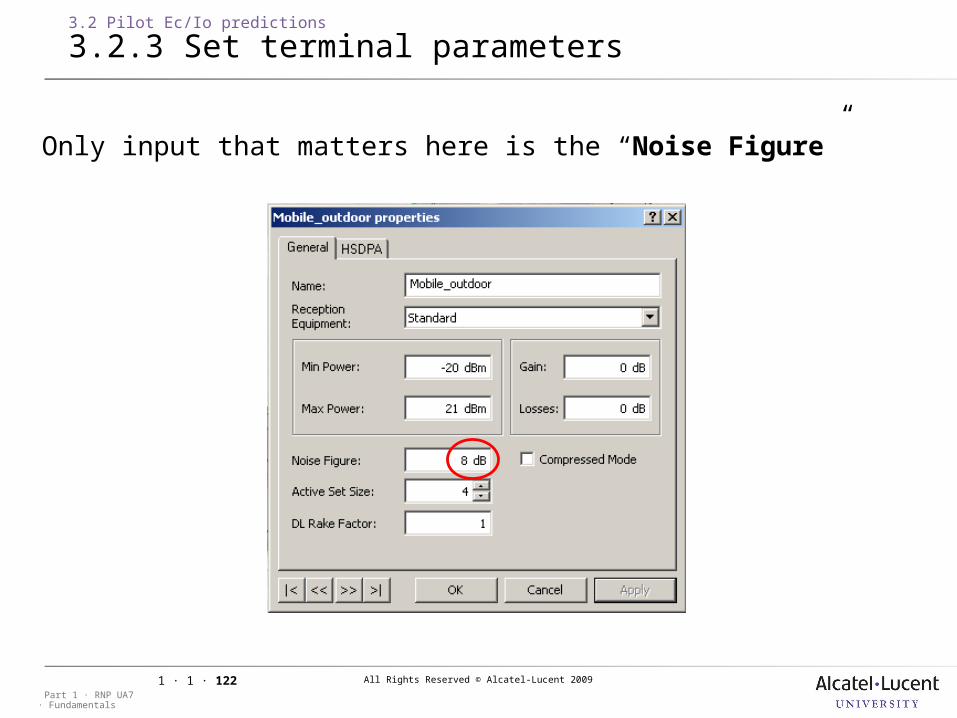
3.2.3 Set terminal parameters
Only input that matters here is the “Noise Figure”
All Rights Reserved © Alcatel-Lucent 2009
· FundamentalsPart 1 · RNP UA7
1 · 1 · 123
3.2 Pilot Ec/Io predictions
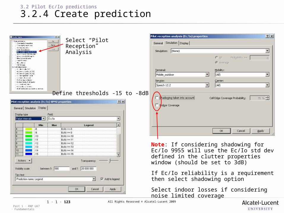
3.2.4 Create prediction
Note: If considering shadowing for Ec/Io 9955 will use the Ec/Io std dev defined in the clutter properties window (should be set to 3dB)
If Ec/Io reliability is a requirement then select shadowing option
Select indoor losses if considering noise limited coverage
Define thresholds -15 to -8dB
Select “Pilot Reception Analysis”
All Rights Reserved © Alcatel-Lucent 2009
· FundamentalsPart 1 · RNP UA7
1 · 1 · 124
3 WCDMA RNP Predictions
3.3 Effective service area predictions
Objective: Identify coverage areas for each serviceSteps: 1) Set Transmitter Properties 2) Set Cell Parameters 3) Define Penetration Margins, Orthogonality & Shadowing 4) Set Terminal Characteristics 5) Define Service Parameters 6) Create Prediction
All Rights Reserved © Alcatel-Lucent 2009
· FundamentalsPart 1 · RNP UA7
1 · 1 · 125
3.3 Effective service area predictions
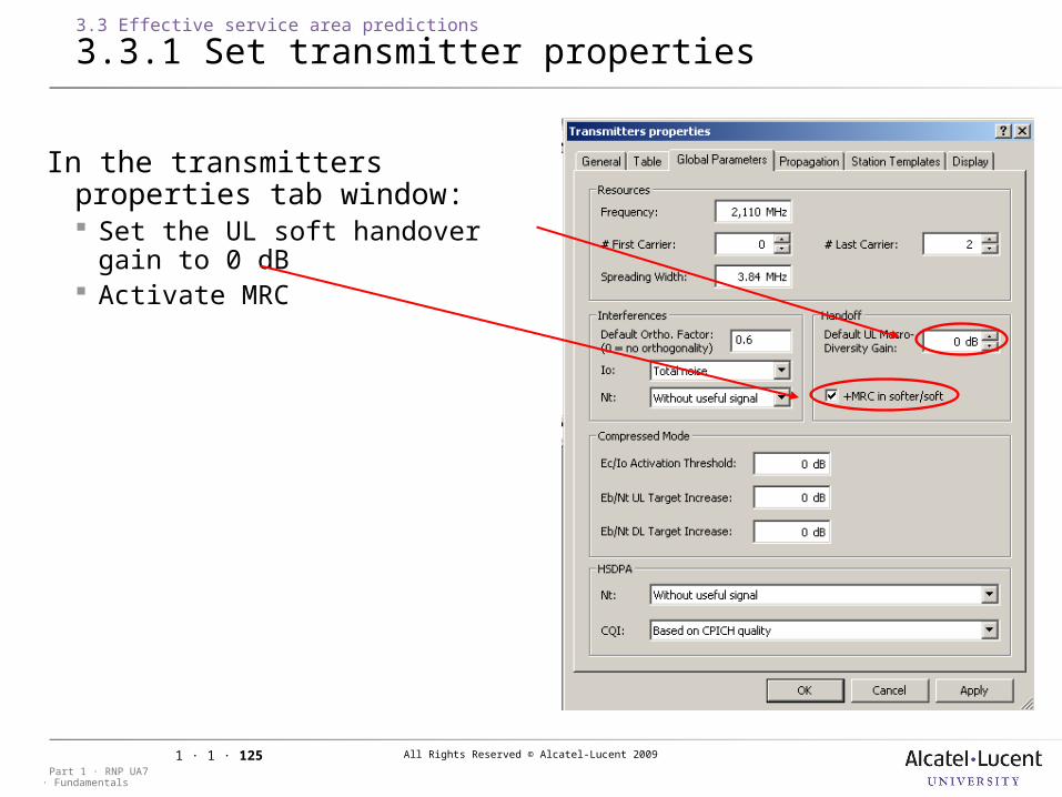
3.3.1 Set transmitter properties
In the transmitters properties tab window: Set the UL soft handover gain to 0
dB Activate MRC
All Rights Reserved © Alcatel-Lucent 2009
· FundamentalsPart 1 · RNP UA7
1 · 1 · 126
3.3 Effective service area predictions
3.3.2 Set cell parameters
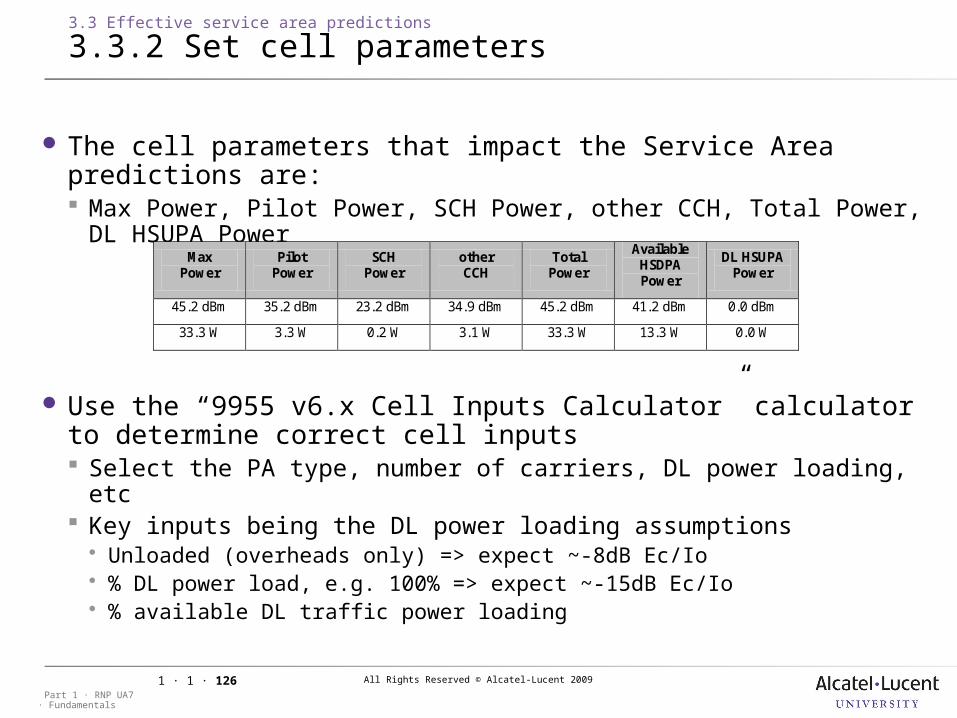
The cell parameters that impact the Service Area predictions are: Max Power, Pilot Power, SCH Power, other CCH, Total Power, DL
HSUPA Power
Use the “9955 v6.x Cell Inputs Calculator” calculator to determine correct cell inputs Select the PA type, number of carriers, DL power loading, etc Key inputs being the DL power loading assumptions Unloaded (overheads only) => expect ~-8dB Ec/Io % DL power load, e.g. 100% => expect ~-15dB Ec/Io % available DL traffic power loading
Max Power
Pilot Power
SCH Power
other CCH
Total Power
Available HSDPA Power
DL HSUPA Power
45.2 dBm 35.2 dBm 23.2 dBm 34.9 dBm 45.2 dBm 41.2 dBm 0.0 dBm
33.3 W 3.3 W 0.2 W 3.1 W 33.3 W 13.3 W 0.0 W
All Rights Reserved © Alcatel-Lucent 2009
· FundamentalsPart 1 · RNP UA7
1 · 1 · 127
3.3 Effective service area predictions
3.3.3 Define pen. margins, orthog. & shad.
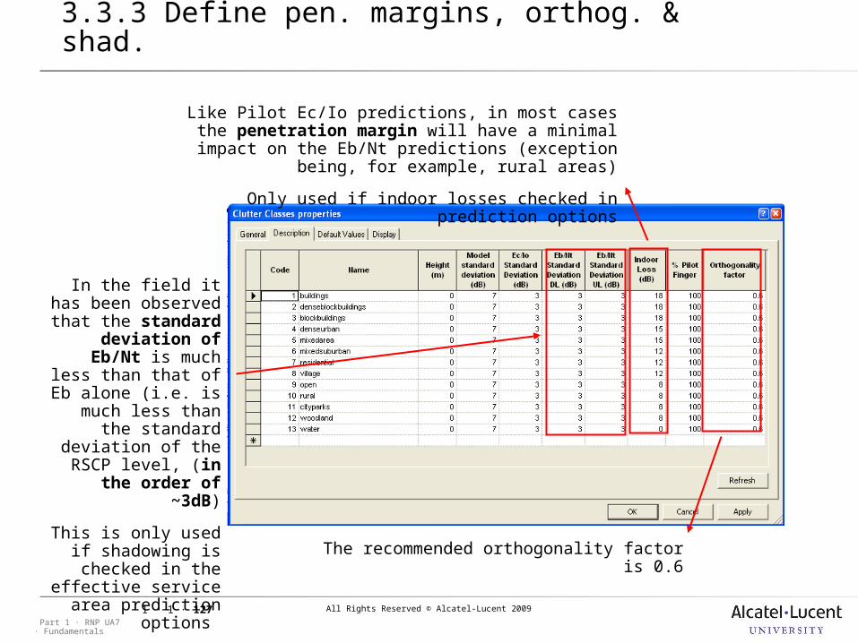
Like Pilot Ec/Io predictions, in most cases the penetration margin will have a minimal impact on the Eb/Nt predictions (exception being, for example,
rural areas)
Only used if indoor losses checked in prediction options
In the field it has been observed that
the standard deviation of Eb/Nt
is much less than that of Eb alone (i.e.
is much less than the standard
deviation of the RSCP level, (in the
order of ~3dB)
This is only used if shadowing is
checked in the effective service area prediction
options
The recommended orthogonality factor is 0.6
All Rights Reserved © Alcatel-Lucent 2009
· FundamentalsPart 1 · RNP UA7
1 · 1 · 128
3.3 Effective service area predictions
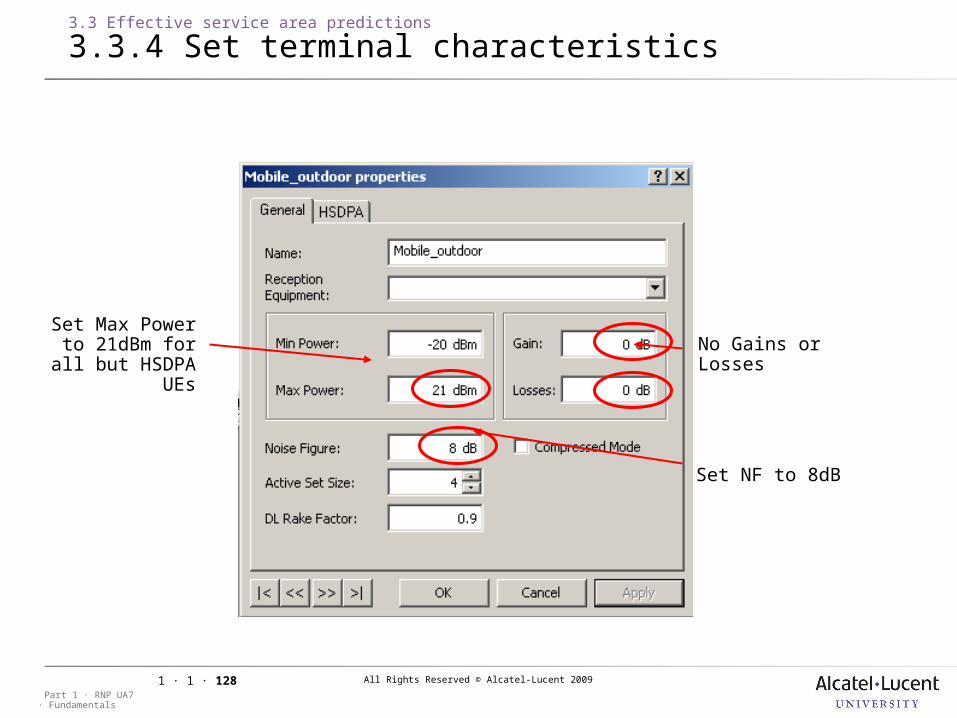
3.3.4 Set terminal characteristics
Set Max Power to 21dBm for all but HSDPA UEs
No Gains or Losses
Set NF to 8dB
All Rights Reserved © Alcatel-Lucent 2009
· FundamentalsPart 1 · RNP UA7
1 · 1 · 129
3.3 Effective service area predictions
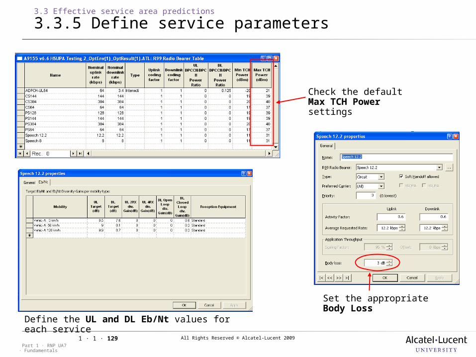
3.3.5 Define service parameters
Define the UL and DL Eb/Nt values for each service
Check the default Max TCH Power settings
Set the appropriate Body Loss
All Rights Reserved © Alcatel-Lucent 2009
· FundamentalsPart 1 · RNP UA7
1 · 1 · 130
3.3 Effective service area predictions
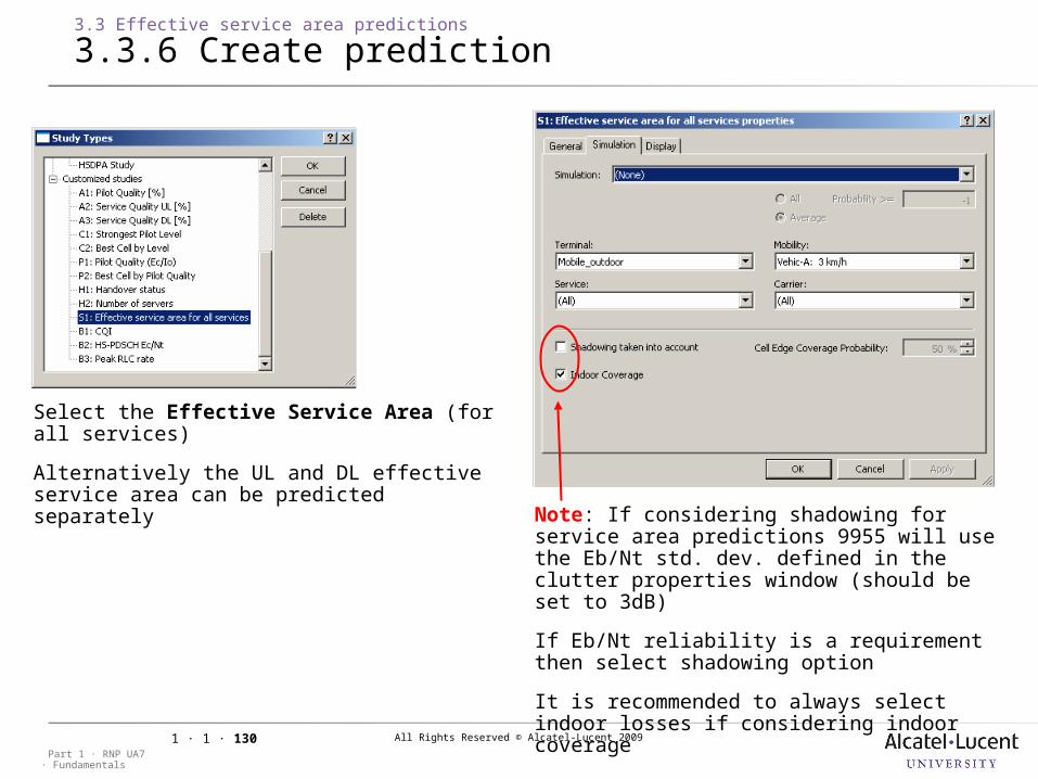
3.3.6 Create prediction
Note: If considering shadowing for service area predictions 9955 will use the Eb/Nt std. dev. defined in the clutter properties window (should be set to 3dB)
If Eb/Nt reliability is a requirement then select shadowing option
It is recommended to always select indoor losses if considering indoor coverage
Select the Effective Service Area (for all services)
Alternatively the UL and DL effective service area can be predicted separately

All Rights Reserved © Alcatel-Lucent 2009
· FundamentalsPart 1 · RNP UA7
1 · 1 · 131
3 WCDMA RNP Predictions
3.4 HSDPA & HSUPA predictions
Objective: Demonstrate the HSPA throughputs over the areaSteps: 1) Set Transmitter Properties 2) Set Cell Parameters 3) Set Reception Equipment Parameters 4) Set Terminal Characteristics 5) Define Mobility Parameters 6) Define Service Parameters 7) Define HSPA Radio Bearers 8) Create Prediction
All Rights Reserved © Alcatel-Lucent 2009
· FundamentalsPart 1 · RNP UA7
1 · 1 · 132
3.4 HSDPA & HSUPA predictions
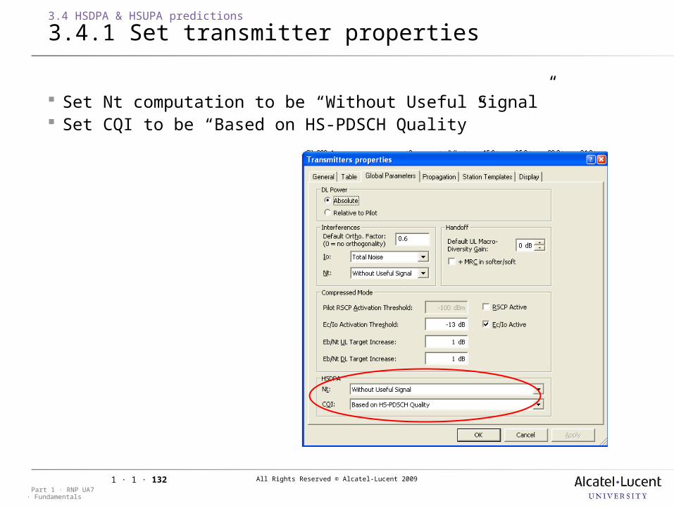
3.4.1 Set transmitter properties
Set Nt computation to be “Without Useful Signal” Set CQI to be “Based on HS-PDSCH Quality”
All Rights Reserved © Alcatel-Lucent 2009
· FundamentalsPart 1 · RNP UA7
1 · 1 · 133
3.4 HSDPA & HSUPA predictions
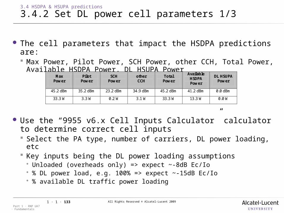
3.4.2 Set DL power cell parameters 1/3
The cell parameters that impact the HSDPA predictions are: Max Power, Pilot Power, SCH Power, other CCH, Total Power,
Available HSDPA Power, DL HSUPA Power
Use the “9955 v6.x Cell Inputs Calculator” calculator to determine correct cell inputs Select the PA type, number of carriers, DL power loading, etc Key inputs being the DL power loading assumptions Unloaded (overheads only) => expect ~-8dB Ec/Io % DL power load, e.g. 100% => expect ~-15dB Ec/Io % available DL traffic power loading
Max Power
Pilot Power
SCH Power
other CCH
Total Power
Available HSDPA Power
DL HSUPA Power
45.2 dBm 35.2 dBm 23.2 dBm 34.9 dBm 45.2 dBm 41.2 dBm 0.0 dBm
33.3 W 3.3 W 0.2 W 3.1 W 33.3 W 13.3 W 0.0 W
All Rights Reserved © Alcatel-Lucent 2009
· FundamentalsPart 1 · RNP UA7
1 · 1 · 134
Input Assumptions
PA Type MCPA 45W - 2100
Number of Carriers 1
Max PA Power 33.4 W
HSDPA Yes
HSUPA Yes
DCH Power Loading 22%
HSDPA Power Loading 22%
Adjacent DCH Power Loading 100%
Adjacent HSDPA Power Loading 50%
DCH UL Cell Load 25%
HSUPA UL Cell Load 25%
Pilot % 10%
HSUPA CCH Overhead 5%
Total Overheads 20%
P-SCH Pilot Delta -5.0 dB
P-SCH % Transmission Time 10%
S-CCH Pilot Delta -5.0 dB
S-CCH % Transmission Time 10%
Total CCH 6.7 W
P-SCH 1.1 W
S-CCH 1.1 W
UL Reuse Factor 1.8
3.4 HSDPA & HSUPA predictions
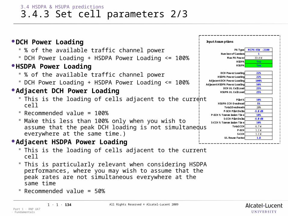
3.4.3 Set cell parameters 2/3
DCH Power Loading % of the available traffic channel power DCH Power Loading + HSDPA Power Loading <= 100%
HSDPA Power Loading % of the available traffic channel power DCH Power Loading + HSDPA Power Loading <= 100%
Adjacent DCH Power Loading This is the loading of cells adjacent to the current cell Recommended value = 100% Make this less than 100% only when you wish to assume
that the peak DCH loading is not simultaneous everywhere at the same time.)
Adjacent HSDPA Power Loading This is the loading of cells adjacent to the current cell This is particularly relevant when considering HSDPA
performances, where you may wish to assume that the peak rates are not simultaneous everywhere at the same time
Recommended value = 50%

All Rights Reserved © Alcatel-Lucent 2009
· FundamentalsPart 1 · RNP UA7
1 · 1 · 135
3.4 HSDPA & HSUPA predictions
3.4.4 Set UL cell parameters 3/3
The cell parameters that impact the HSUPA predictions are: Max UL Load Factor, UL Load Factor, UL Load Factor Due to
HSUPA, UL Reuse Factor
Use the “9955 v6.x Cell Inputs Calculator” calculator to determine correct cell inputs: Define UL Cell Load due to DCH traffic “UL Cell Load” Enter the “UL Cell Load due to HSUPA traffic” Define the “Max UL Cell Load” >= DCH + HSUPA
The recommended UL Reuse Factor is 1.8
Max UL Load Factor
UL Load Factor
UL Load Factor Due to HSUPA
UL Reuse Factor
50% 50% 0% 1.8
• Total UL Cell Load •50%•HSUPA UL Cell Load Fraction •25%
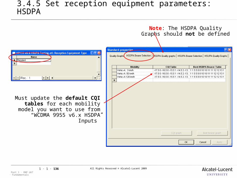
All Rights Reserved © Alcatel-Lucent 2009
· FundamentalsPart 1 · RNP UA7
1 · 1 · 136
3.4 HSDPA & HSUPA predictions
3.4.5 Set reception equipment parameters: HSDPA
Must update the default CQI tables for each mobility model you want to use from “WCDMA
9955 v6.x HSDPA Inputs”
Note: The HSDPA Quality Graphs should not be defined
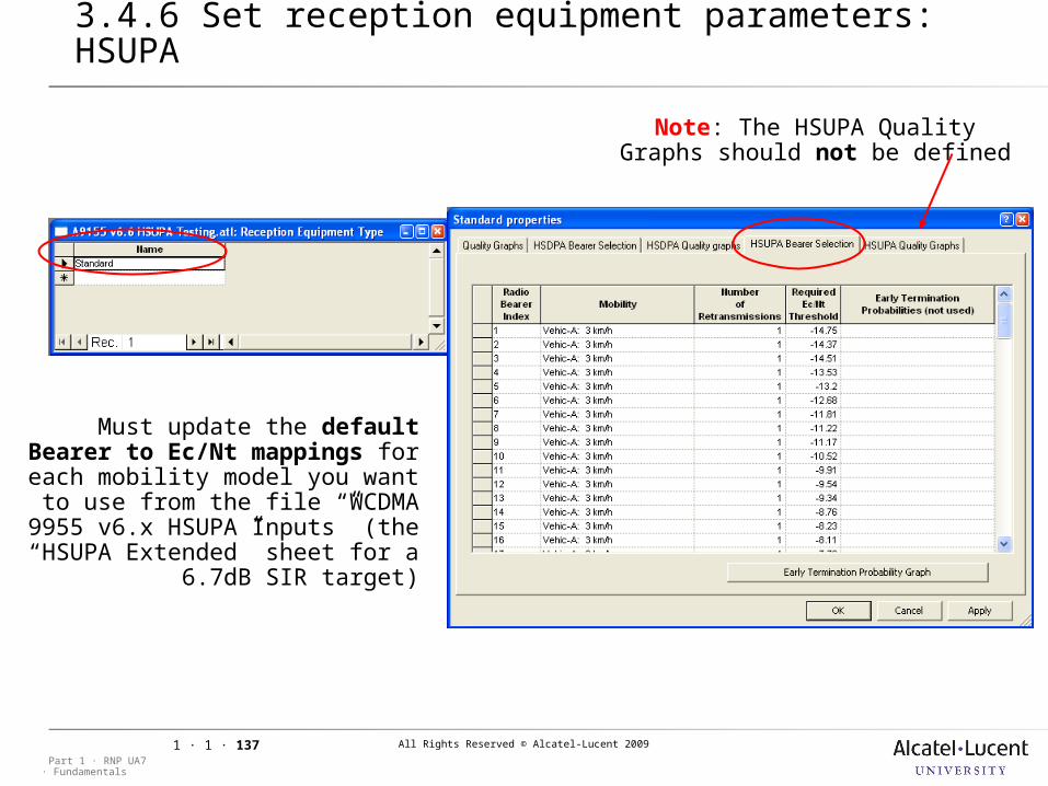
All Rights Reserved © Alcatel-Lucent 2009
· FundamentalsPart 1 · RNP UA7
1 · 1 · 137
3.4 HSDPA & HSUPA predictions
3.4.6 Set reception equipment parameters: HSUPA
Must update the default Bearer to Ec/Nt mappings for each
mobility model you want to use from the file “WCDMA 9955 v6.x
HSUPA Inputs” (the “HSUPA Extended” sheet for a 6.7dB SIR
target)
Note: The HSUPA Quality Graphs should not be defined
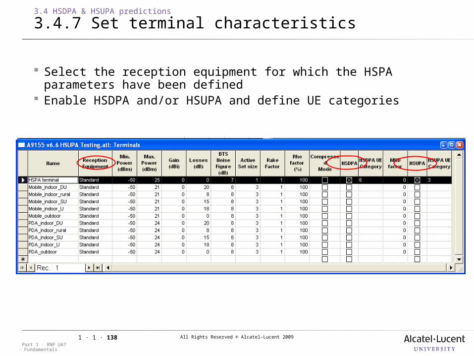
All Rights Reserved © Alcatel-Lucent 2009
· FundamentalsPart 1 · RNP UA7
1 · 1 · 138
3.4 HSDPA & HSUPA predictions
3.4.7 Set terminal characteristics
Select the reception equipment for which the HSPA parameters have been defined
Enable HSDPA and/or HSUPA and define UE categories
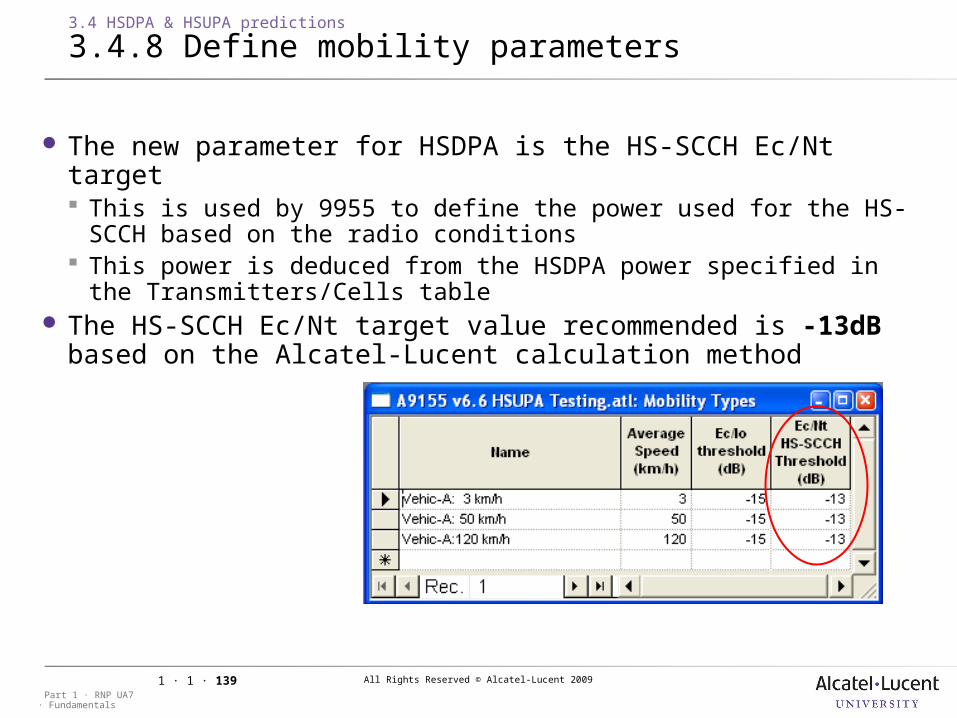
All Rights Reserved © Alcatel-Lucent 2009
· FundamentalsPart 1 · RNP UA7
1 · 1 · 139
3.4 HSDPA & HSUPA predictions
3.4.8 Define mobility parameters
The new parameter for HSDPA is the HS-SCCH Ec/Nt target This is used by 9955 to define the power used for the HS-SCCH based
on the radio conditions This power is deduced from the HSDPA power specified in the
Transmitters/Cells table The HS-SCCH Ec/Nt target value recommended is -13dB based
on the Alcatel-Lucent calculation method
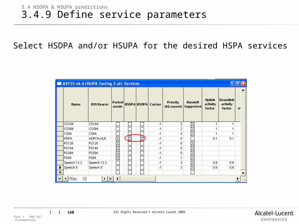
All Rights Reserved © Alcatel-Lucent 2009
· FundamentalsPart 1 · RNP UA7
1 · 1 · 140
3.4 HSDPA & HSUPA predictions
3.4.9 Define service parameters
Select HSDPA and/or HSUPA for the desired HSPA services
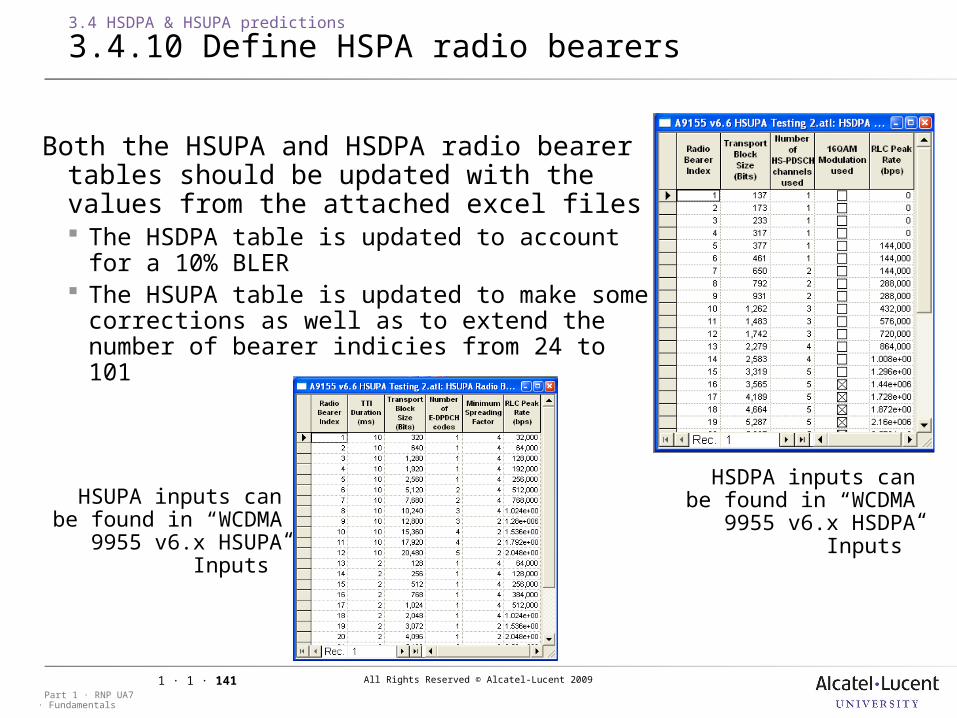
All Rights Reserved © Alcatel-Lucent 2009
· FundamentalsPart 1 · RNP UA7
1 · 1 · 141
3.4 HSDPA & HSUPA predictions
3.4.10 Define HSPA radio bearers
Both the HSUPA and HSDPA radio bearer tables should be updated with the values from the attached excel files The HSDPA table is updated to account for a
10% BLER The HSUPA table is updated to make some
corrections as well as to extend the number of bearer indicies from 24 to 101
HSUPA inputs can be found in “WCDMA 9955 v6.x HSUPA
Inputs”
HSDPA inputs can be found in “WCDMA 9955 v6.x HSDPA
Inputs”
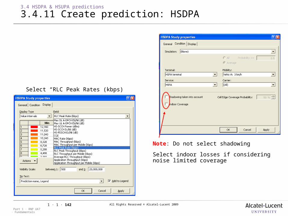
All Rights Reserved © Alcatel-Lucent 2009
· FundamentalsPart 1 · RNP UA7
1 · 1 · 142
3.4 HSDPA & HSUPA predictions
3.4.11 Create prediction: HSDPA
Select “RLC Peak Rates (kbps)
Note: Do not select shadowing
Select indoor losses if considering noise limited coverage

All Rights Reserved © Alcatel-Lucent 2009
· FundamentalsPart 1 · RNP UA7
1 · 1 · 143
3.4 HSDPA & HSUPA predictions
3.4.12 Create prediction: HSUPA
Select “RLC Peak Rates (kbps)
Note: Do not select shadowing
Select indoor losses if considering noise limited coverage
Selecting “Single User” assumes that a single user takes the entire UL HSUPA cell load limit
Selecting “Shared” means that the HSUPA cell load limit is shared amongst the number of
user defined for HSUPA in the cell properties sheet “Number of HSUPA Users”
All Rights Reserved © Alcatel-Lucent 2009
· FundamentalsPart 1 · RNP UA7
1 · 1 · 144
4 WCDMA Traffic Simulations
All Rights Reserved © Alcatel-Lucent 2009
· FundamentalsPart 1 · RNP UA7
1 · 1 · 145
4 WCDMA Traffic Simulations
4.1 UMTS traffic simulations
Objective: to be able to check that the network capacity is in line with the
traffic demand by performing traffic simulations with a RNP tool
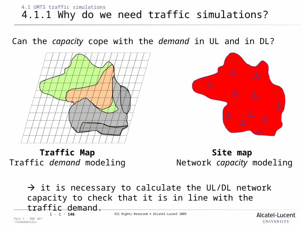
All Rights Reserved © Alcatel-Lucent 2009
· FundamentalsPart 1 · RNP UA7
1 · 1 · 146
4.1 UMTS traffic simulations
4.1.1 Why do we need traffic simulations?
Traffic MapTraffic demand modeling
Can the capacity cope with the demand in UL and in DL?
Site map Network capacity modeling
it is necessary to calculate the UL/DL network capacity to check that it is in line with the traffic demand.
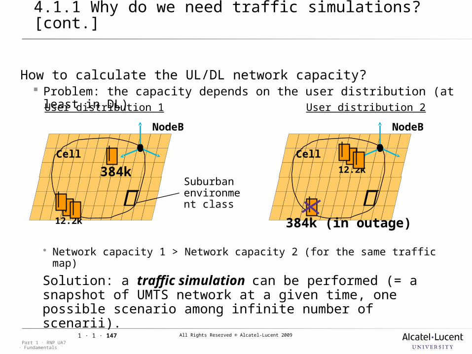
All Rights Reserved © Alcatel-Lucent 2009
· FundamentalsPart 1 · RNP UA7
1 · 1 · 147
4.1 UMTS traffic simulations
4.1.1 Why do we need traffic simulations? [cont.]
How to calculate the UL/DL network capacity? Problem: the capacity depends on the user distribution (at least in
DL)
Solution: a traffic simulation can be performed (= a snapshot of UMTS network at a given time, one possible scenario among infinite number of scenarii).
User distribution 1 User distribution 2
384k
12.2k
Cell
NodeB
12.2k
384k (in outage)
Cell
NodeB
Suburban environment class
Network capacity 1 > Network capacity 2 (for the same traffic map)
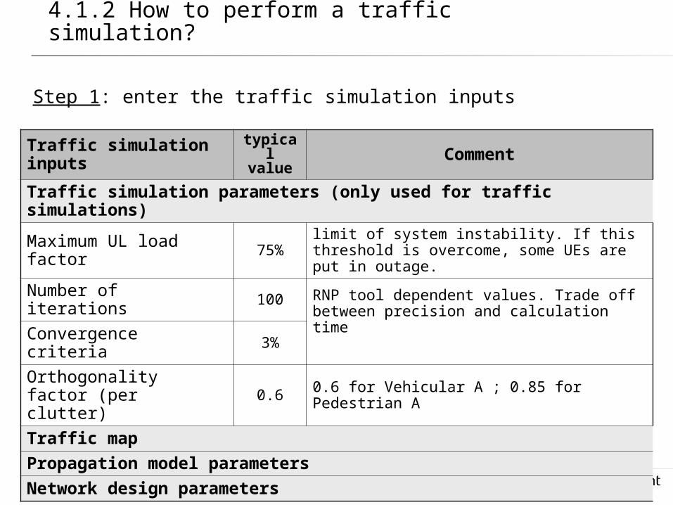
All Rights Reserved © Alcatel-Lucent 2009
· FundamentalsPart 1 · RNP UA7
1 · 1 · 148
4.1 UMTS traffic simulations
4.1.2 How to perform a traffic simulation?
Traffic simulation inputs
typicalvalue Comment
Traffic simulation parameters (only used for traffic simulations)
Maximum UL load factor 75% limit of system instability. If this threshold is
overcome, some UEs are put in outage.
Number of iterations 100 RNP tool dependent values. Trade off between precision and calculation time
Convergence criteria 3%
Orthogonality factor (per clutter) 0.6 0.6 for Vehicular A ; 0.85 for Pedestrian A
Traffic map
Propagation model parameters
Network design parameters
Step 1: enter the traffic simulation inputs
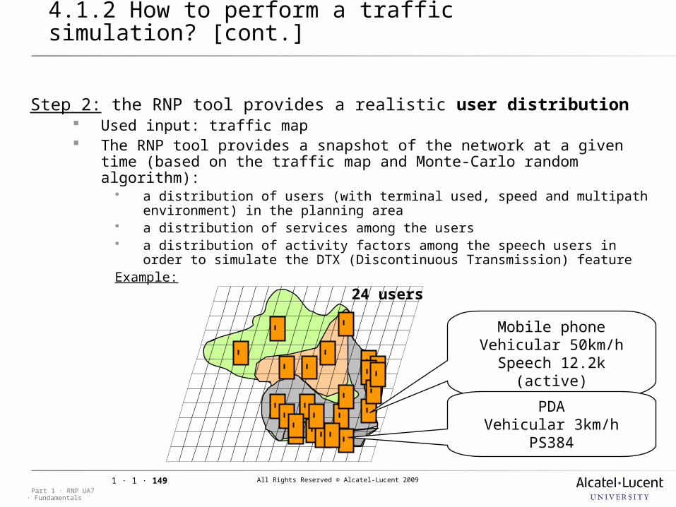
All Rights Reserved © Alcatel-Lucent 2009
· FundamentalsPart 1 · RNP UA7
1 · 1 · 149
4.1 UMTS traffic simulations
4.1.2 How to perform a traffic simulation? [cont.]
Step 2: the RNP tool provides a realistic user distribution Used input: traffic map The RNP tool provides a snapshot of the network at a given time (based
on the traffic map and Monte-Carlo random algorithm): a distribution of users (with terminal used, speed and multipath
environment) in the planning area a distribution of services among the users a distribution of activity factors among the speech users in order to simulate
the DTX (Discontinuous Transmission) featureExample:
Mobile phoneVehicular 50km/h
Speech 12.2k (active)
PDAVehicular 3km/h
PS384
24 users

All Rights Reserved © Alcatel-Lucent 2009
· FundamentalsPart 1 · RNP UA7
1 · 1 · 150
4.1 UMTS traffic simulations
4.1.2 How to perform a traffic simulation? [cont.]
Step 3: the RNP tool checks the UL/DL service availability for each user Used inputs: user distribution (see Step1) +Propagation model
parameters+Network design parameters+ traffic simulations parameters
UL/DL link loss calculations are performed iteratively due to (fast) power control mechanisms in order to get: needed UE TX power for each UE needed NodeB TX power for each cell
Each of the following conditions is checked: if one of them is not fulfilled, the concerned user will be ejected (service blocked):
Conditions in UL:1) needed UE TX power < Maximum UE TX power2) UL load factor < Maximum UL load factor (typical value: 75%)3) enough UL NodeB processing capacity
Conditions in DL:1) CPICH Ec/Io > ( CPICH Ec/Io)required
2) needed NodeB TX power < Maximum NodeB TX power (ie DL Power load<100%)
3) (for each traffic channel) needed TX power < Max TX power per channel
4) enough DL NodeB processing capacity 5) needed number of codes < max
number of codes
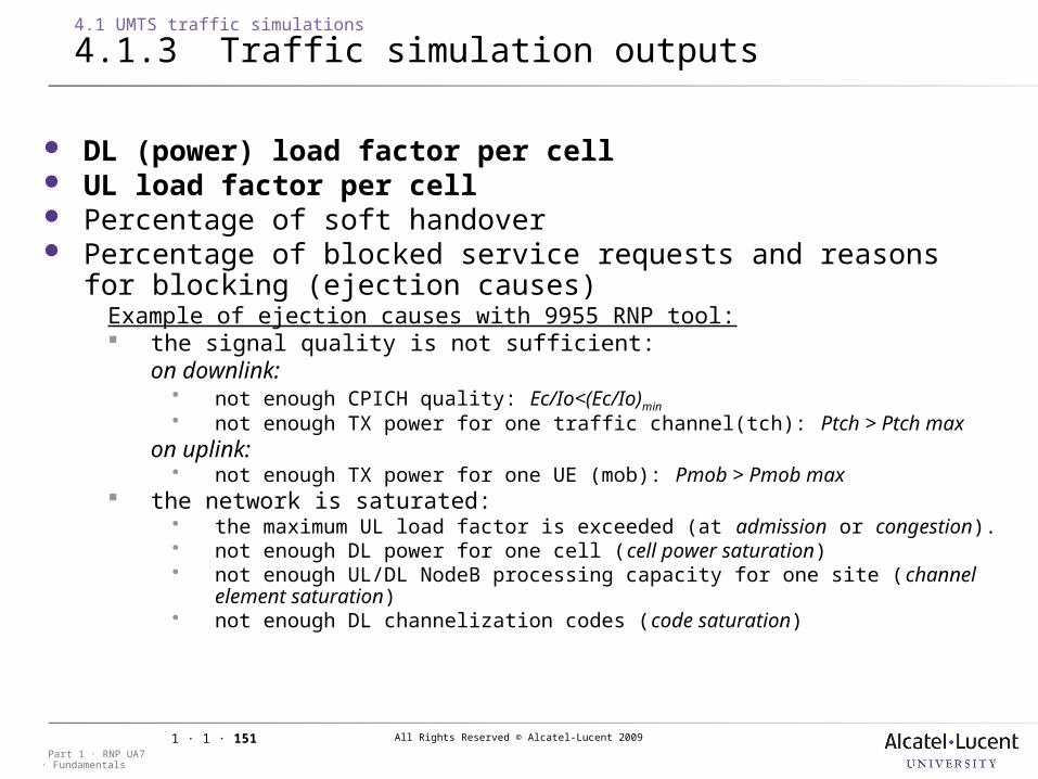
All Rights Reserved © Alcatel-Lucent 2009
· FundamentalsPart 1 · RNP UA7
1 · 1 · 151
4.1 UMTS traffic simulations
4.1.3 Traffic simulation outputs
DL (power) load factor per cell UL load factor per cell Percentage of soft handover Percentage of blocked service requests and reasons for
blocking (ejection causes)Example of ejection causes with 9955 RNP tool: the signal quality is not sufficient:
on downlink: not enough CPICH quality: Ec/Io<(Ec/Io)min
not enough TX power for one traffic channel(tch): Ptch > Ptch maxon uplink: not enough TX power for one UE (mob): Pmob > Pmob max
the network is saturated: the maximum UL load factor is exceeded (at admission or congestion). not enough DL power for one cell (cell power saturation) not enough UL/DL NodeB processing capacity for one site (channel element
saturation) not enough DL channelization codes (code saturation)
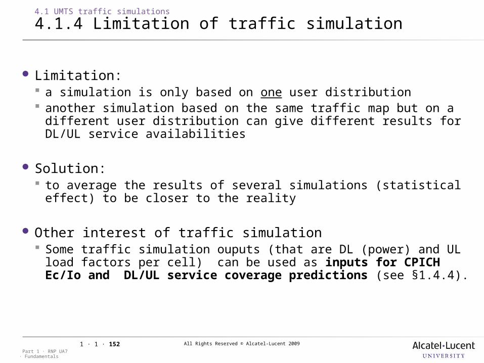
All Rights Reserved © Alcatel-Lucent 2009
· FundamentalsPart 1 · RNP UA7
1 · 1 · 152
4.1 UMTS traffic simulations
4.1.4 Limitation of traffic simulation
Limitation: a simulation is only based on one user distribution another simulation based on the same traffic map but on a different
user distribution can give different results for DL/UL service availabilities
Solution: to average the results of several simulations (statistical effect) to be
closer to the reality
Other interest of traffic simulation Some traffic simulation ouputs (that are DL (power) and UL load
factors per cell) can be used as inputs for CPICH Ec/Io and DL/UL service coverage predictions (see §1.4.4).
All Rights Reserved © Alcatel-Lucent 2009
· FundamentalsPart 1 · RNP UA7
1 · 1 · 153
4.1.4 Limitation of traffic simulation
All Rights Reserved © Alcatel-Lucent 2009
· FundamentalsPart 1 · RNP UA7
1 · 1 · 154
5 Link Budget (in Uplink)
All Rights Reserved © Alcatel-Lucent 2009
· FundamentalsPart 1 · RNP UA7
1 · 1 · 155
5 Link Budget (in Uplink)
5.1 Session presentation
Objective: to be able to calculate the cell range for a given service by
doing a link budget in UL.
to be able to describe the typical UMTS radio effects in UL.
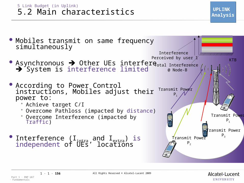
All Rights Reserved © Alcatel-Lucent 2009
· FundamentalsPart 1 · RNP UA7
1 · 1 · 156
5 Link Budget (in Uplink)
5.2 Main characteristics
KTB
Transmit PowerP1
Transmit PowerP2
Transmit PowerP3
Transmit PowerPi
Total Interference @ Node-B
Interference Perceived by user 1
Mobiles transmit on same frequency simultaneously
Asynchronous Other UEs interfere System is interference limited
According to Power Control instructions, Mobiles adjust their power to: Achieve target C/I Overcome Pathloss (impacted by distance) Overcome Interference (impacted by Traffic)
Interference (Iintra and Iextra) is independent of UEs’ locations
UPLINK AnalysisUPLINK Analysis
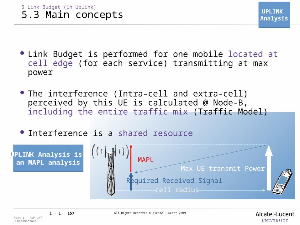
All Rights Reserved © Alcatel-Lucent 2009
· FundamentalsPart 1 · RNP UA7
1 · 1 · 157
Link Budget is performed for one mobile located at cell edge (for each service) transmitting at max power
The interference (Intra-cell and extra-cell) perceived by this UE is calculated @ Node-B, including the entire traffic mix (Traffic Model)
Interference is a shared resource
5 Link Budget (in Uplink)
5.3 Main concepts
cell radius
MAPL
Required Received Signal
Max UE transmit Power
UPLINK Analysis is an MAPL analysis
UPLINK Analysis is an MAPL analysis
UPLINK AnalysisUPLINK Analysis
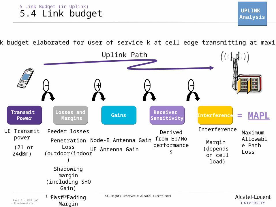
All Rights Reserved © Alcatel-Lucent 2009
· FundamentalsPart 1 · RNP UA7
1 · 1 · 158
5 Link Budget (in Uplink)
5.4 Link budget
Receiver SensitivityReceiver
SensitivityTransmit
PowerTransmit
PowerLosses and Margins
Losses and Margins GainsGains InterferenceInterference
Feeder losses
Penetration Loss (outdoor/indoor)
Shadowing margin (including
SHO Gain)
Fast Fading Margin
Body Loss
Node-B Antenna Gain
UE Antenna Gain
Derived from Eb/No
performances
Interference Margin
(depends on cell load)
= MAPL
UE Transmitpower
(21 or 24dBm)
Uplink Path
Maximum Allowable Path Loss
UL link budget elaborated for user of service k at cell edge transmitting at maximum power
UPLINK AnalysisUPLINK Analysis
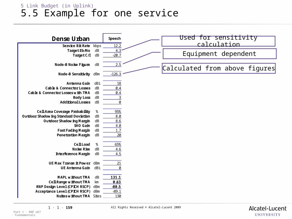
All Rights Reserved © Alcatel-Lucent 2009
· FundamentalsPart 1 · RNP UA7
1 · 1 · 159
5 Link Budget (in Uplink)
5.5 Example for one service
Used for sensitivity calculation
Equipment dependent
Calculated from above figures
Dense Urban Speech
Service Bit Rate kbps 12.2Target Eb/No dB 4.3
Target C/I dB -20.7
Node-B Noise Figure dB 2.5
Node-B Sensitivity dBm -126.3
Antenna Gain dBi 18Cable & Connector Losses dB 0.4
Cable & Connector Losses with TMA dB 0.4Body Loss dB 3
Additional Losses dB 0
Cell Area Coverage Probability % 95%Outdoor Shadowing Standard Deviation dB 8.0
Outdoor Shadowing Margin dB 8.6SHO Gain dB 4.0
Fast Fading Margin dB 1.7Penetration Margin dB 20
Cell Load % 65%Noise Rise dB 4.6
Interference Margin dB 4.5
UE Max Transmit Power dBm 21UE Antenna Gain dBi 0
MAPL without TMA dB 131.1Cell Range without TMA km 0.63
RNP Design Level (CPICH RSCP) dBm -80.5Acceptance Level (CPICH RSCP) dBm -89.1
Nsites without TMA Sites 130
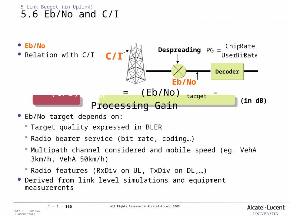
All Rights Reserved © Alcatel-Lucent 2009
· FundamentalsPart 1 · RNP UA7
1 · 1 · 160
Eb/No Relation with C/I
Eb/No target depends on: Target quality expressed in BLER
Radio bearer service (bit rate, coding…)
Multipath channel considered and mobile speed (eg. VehA 3km/h, VehA 50km/h)
Radio features (RxDiv on UL, TxDiv on DL,…) Derived from link level simulations and equipment measurements
5 Link Budget (in Uplink)
5.6 Eb/No and C/I
Eb/No(C/I) target = (Eb/No) target - Processing
Gain(in dB)
C/I
DecoderDecoder
DespreadingRateBitUser
RateChipPG
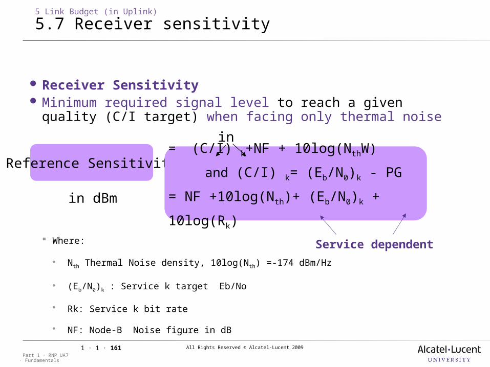
All Rights Reserved © Alcatel-Lucent 2009
· FundamentalsPart 1 · RNP UA7
1 · 1 · 161
Receiver Sensitivity Minimum required signal level to reach a given quality (C/I
target) when facing only thermal noise
Where:
Nth Thermal Noise density, 10log(Nth) =-174 dBm/Hz
(Eb/N0)k : Service k target Eb/No
Rk: Service k bit rate
NF: Node-B Noise figure in dB
5 Link Budget (in Uplink)
5.7 Receiver sensitivity
in dB
Reference Sensitivity = (C/I) k+NF + 10log(NthW)
and (C/I) k= (Eb/N0)k - PG
= NF +10log(Nth)+ (Eb/N0)k + 10log(Rk)
Service dependent
in dBm
All Rights Reserved © Alcatel-Lucent 2009
· FundamentalsPart 1 · RNP UA7
1 · 1 · 162
5 Link Budget (in Uplink)
5.8 Exercise
Compute Node-B sensitivity in Veh A 3km/h for speech 12.2kbps @ 1% BLER For CS64 @ 0.5% BLER
All Rights Reserved © Alcatel-Lucent 2009
· FundamentalsPart 1 · RNP UA7
1 · 1 · 163
5 Link Budget (in Uplink)
5.9 Exercise
Compute Node-B sensitivity in Veh A 3km/h for speech 12.2kbps @ 1% BLER For CS64 @ 0.5% BLER
Example of equipment parameter values: Typical Node-B Noise Figure: 2.5dB @ 2GHz Eb/No figures: 4.9 dB for speech, 3.0dB for CS64

All Rights Reserved © Alcatel-Lucent 2009
· FundamentalsPart 1 · RNP UA7
1 · 1 · 164
5 Link Budget (in Uplink)
5.10 Example for one service
3dB body loss when speech usage (UE near head), 0dB boldy loss when data
usage
Typical gain of Tri-sectored antenna, depends on frequency
band
Depends on feeder type and length an frequency band
For any additional losses that could be introduced (eg diplexer)
Dense Urban Speech
Service Bit Rate kbps 12.2Target Eb/No dB 4.3
Target C/I dB -20.7
Node-B Noise Figure dB 2.5
Node-B Sensitivity dBm -126.3
Antenna Gain dBi 18Cable & Connector Losses dB 0.4
Cable & Connector Losses with TMA dB 0.4Body Loss dB 3
Additional Losses dB 0
Cell Area Coverage Probability % 95%Outdoor Shadowing Standard Deviation dB 8.0
Outdoor Shadowing Margin dB 8.6SHO Gain dB 4.0
Fast Fading Margin dB 1.7Penetration Margin dB 20
Cell Load % 65%Noise Rise dB 4.6
Interference Margin dB 4.5
UE Max Transmit Power dBm 21UE Antenna Gain dBi 0
MAPL without TMA dB 131.1Cell Range without TMA km 0.63
RNP Design Level (CPICH RSCP) dBm -80.5Acceptance Level (CPICH RSCP) dBm -89.1
Nsites without TMA Sites 130
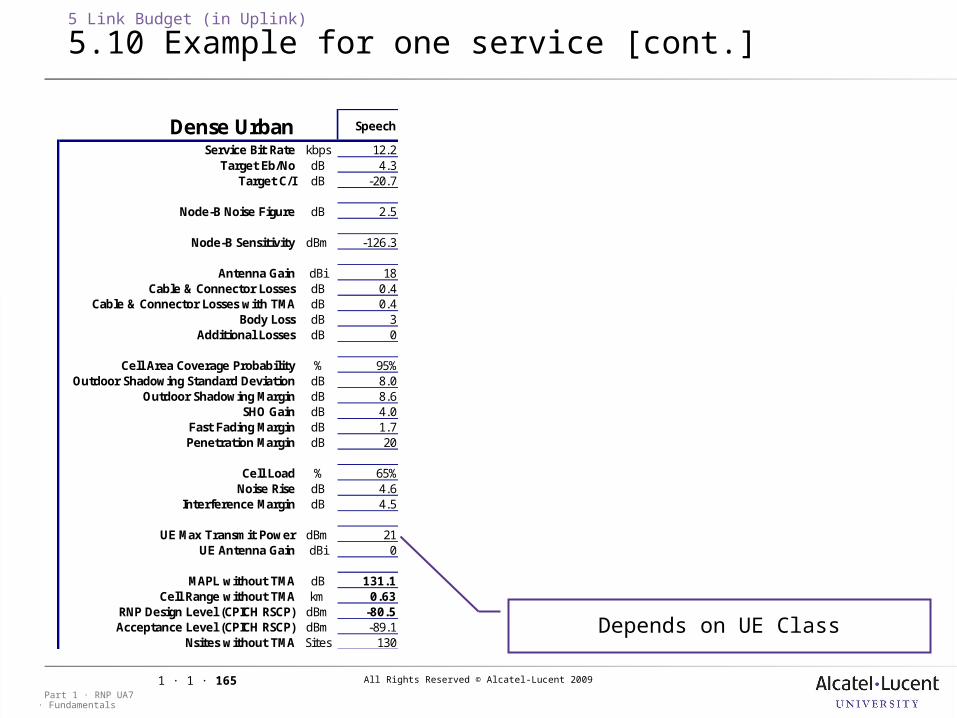
All Rights Reserved © Alcatel-Lucent 2009
· FundamentalsPart 1 · RNP UA7
1 · 1 · 165
5 Link Budget (in Uplink)
5.10 Example for one service [cont.]
Depends on UE Class
Dense Urban Speech
Service Bit Rate kbps 12.2Target Eb/No dB 4.3
Target C/I dB -20.7
Node-B Noise Figure dB 2.5
Node-B Sensitivity dBm -126.3
Antenna Gain dBi 18Cable & Connector Losses dB 0.4
Cable & Connector Losses with TMA dB 0.4Body Loss dB 3
Additional Losses dB 0
Cell Area Coverage Probability % 95%Outdoor Shadowing Standard Deviation dB 8.0
Outdoor Shadowing Margin dB 8.6SHO Gain dB 4.0
Fast Fading Margin dB 1.7Penetration Margin dB 20
Cell Load % 65%Noise Rise dB 4.6
Interference Margin dB 4.5
UE Max Transmit Power dBm 21UE Antenna Gain dBi 0
MAPL without TMA dB 131.1Cell Range without TMA km 0.63
RNP Design Level (CPICH RSCP) dBm -80.5Acceptance Level (CPICH RSCP) dBm -89.1
Nsites without TMA Sites 130
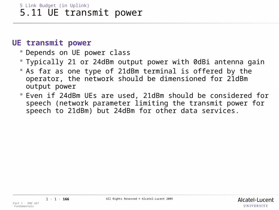
All Rights Reserved © Alcatel-Lucent 2009
· FundamentalsPart 1 · RNP UA7
1 · 1 · 166
5 Link Budget (in Uplink)
5.11 UE transmit power
UE transmit power Depends on UE power class Typically 21 or 24dBm output power with 0dBi antenna gain As far as one type of 21dBm terminal is offered by the operator, the
network should be dimensioned for 21dBm output power Even if 24dBm UEs are used, 21dBm should be considered for speech
(network parameter limiting the transmit power for speech to 21dBm) but 24dBm for other data services.
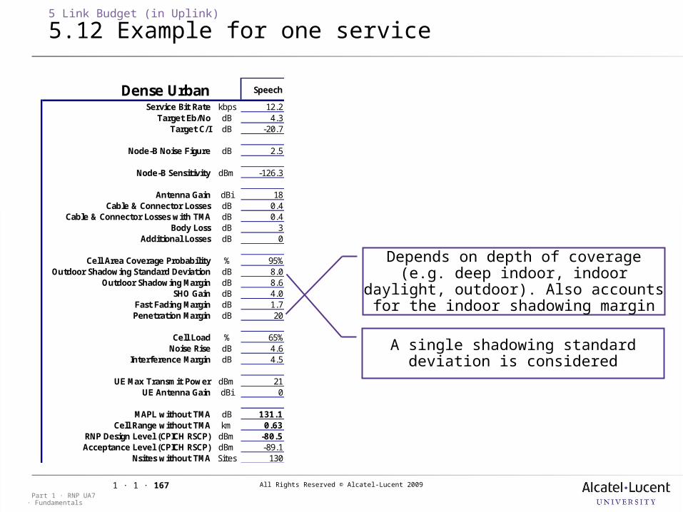
All Rights Reserved © Alcatel-Lucent 2009
· FundamentalsPart 1 · RNP UA7
1 · 1 · 167
5 Link Budget (in Uplink)
5.12 Example for one service
Depends on depth of coverage (e.g. deep indoor, indoor daylight, outdoor). Also accounts for the indoor shadowing
margin
A single shadowing standard deviation is considered
Dense Urban Speech
Service Bit Rate kbps 12.2Target Eb/No dB 4.3
Target C/I dB -20.7
Node-B Noise Figure dB 2.5
Node-B Sensitivity dBm -126.3
Antenna Gain dBi 18Cable & Connector Losses dB 0.4
Cable & Connector Losses with TMA dB 0.4Body Loss dB 3
Additional Losses dB 0
Cell Area Coverage Probability % 95%Outdoor Shadowing Standard Deviation dB 8.0
Outdoor Shadowing Margin dB 8.6SHO Gain dB 4.0
Fast Fading Margin dB 1.7Penetration Margin dB 20
Cell Load % 65%Noise Rise dB 4.6
Interference Margin dB 4.5
UE Max Transmit Power dBm 21UE Antenna Gain dBi 0
MAPL without TMA dB 131.1Cell Range without TMA km 0.63
RNP Design Level (CPICH RSCP) dBm -80.5Acceptance Level (CPICH RSCP) dBm -89.1
Nsites without TMA Sites 130
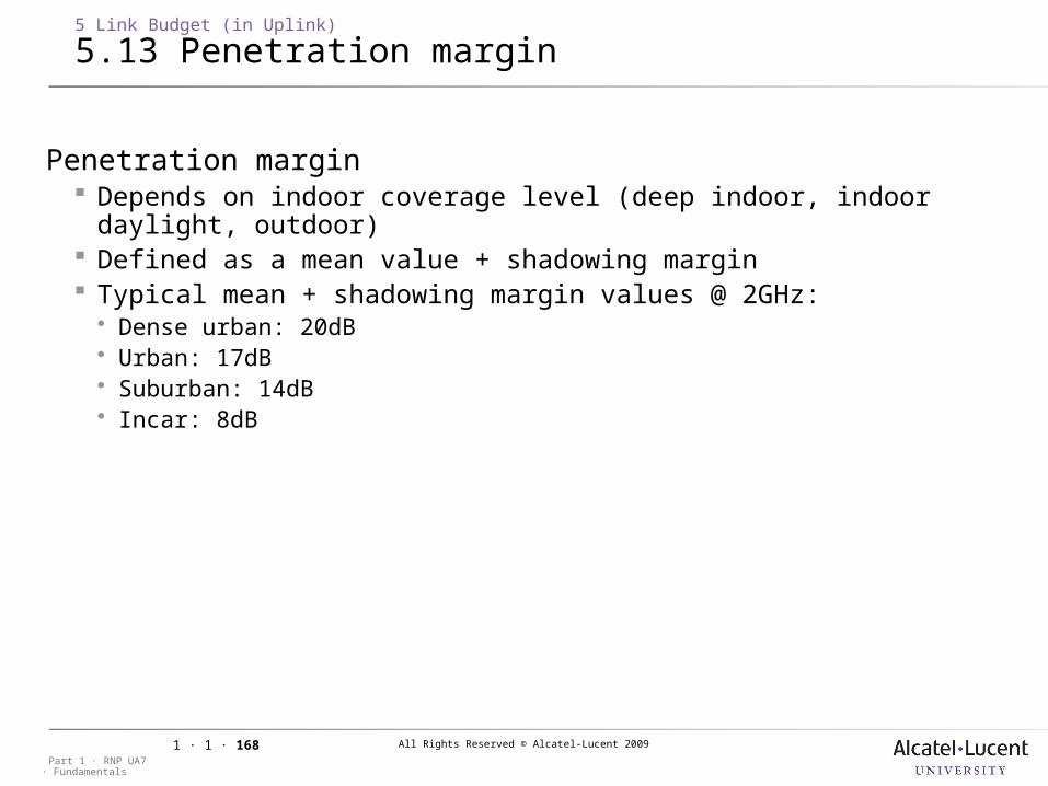
All Rights Reserved © Alcatel-Lucent 2009
· FundamentalsPart 1 · RNP UA7
1 · 1 · 168
5 Link Budget (in Uplink)
5.13 Penetration margin
Penetration margin Depends on indoor coverage level (deep indoor, indoor daylight,
outdoor) Defined as a mean value + shadowing margin Typical mean + shadowing margin values @ 2GHz: Dense urban: 20dB Urban: 17dB Suburban: 14dB Incar: 8dB
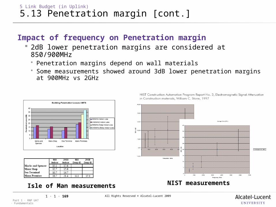
All Rights Reserved © Alcatel-Lucent 2009
· FundamentalsPart 1 · RNP UA7
1 · 1 · 169
5 Link Budget (in Uplink)
5.13 Penetration margin [cont.]
Impact of frequency on Penetration margin 2dB lower penetration margins are considered at 850/900MHz Penetration margins depend on wall materials Some measurements showed around 3dB lower penetration margins at
900MHz vs 2GHz
Isle of Man measurements
NIST measurements
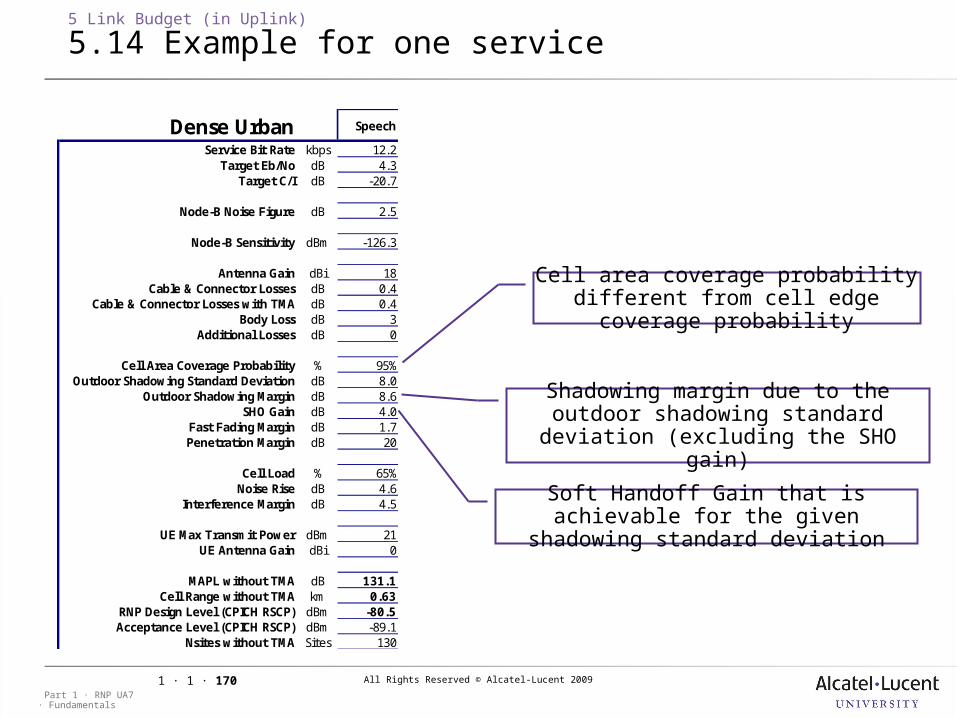
All Rights Reserved © Alcatel-Lucent 2009
· FundamentalsPart 1 · RNP UA7
1 · 1 · 170
5 Link Budget (in Uplink)
5.14 Example for one service
Cell area coverage probability different from cell edge coverage
probability
Shadowing margin due to the outdoor shadowing standard deviation
(excluding the SHO gain)
Soft Handoff Gain that is achievable for the given shadowing standard
deviation
Dense Urban Speech
Service Bit Rate kbps 12.2Target Eb/No dB 4.3
Target C/I dB -20.7
Node-B Noise Figure dB 2.5
Node-B Sensitivity dBm -126.3
Antenna Gain dBi 18Cable & Connector Losses dB 0.4
Cable & Connector Losses with TMA dB 0.4Body Loss dB 3
Additional Losses dB 0
Cell Area Coverage Probability % 95%Outdoor Shadowing Standard Deviation dB 8.0
Outdoor Shadowing Margin dB 8.6SHO Gain dB 4.0
Fast Fading Margin dB 1.7Penetration Margin dB 20
Cell Load % 65%Noise Rise dB 4.6
Interference Margin dB 4.5
UE Max Transmit Power dBm 21UE Antenna Gain dBi 0
MAPL without TMA dB 131.1Cell Range without TMA km 0.63
RNP Design Level (CPICH RSCP) dBm -80.5Acceptance Level (CPICH RSCP) dBm -89.1
Nsites without TMA Sites 130

All Rights Reserved © Alcatel-Lucent 2009
· FundamentalsPart 1 · RNP UA7
1 · 1 · 171
5 Link Budget (in Uplink)
5.15 Shadowing margin
Shadowing margin Shadowing: Slow fading signal level variations due to obstacles Modelled (in dB) as a Gaussian variable with zero-mean and
standard deviation depending on the environment Impact on link budget : Take a margin to ensure the received signal is well received
(above required sensitivity) with a given probability (e.g. in 95% of the cell)
Computation as in GSM. However, in UMTS, a mobile at cell edge is likely to be in soft-handover (SHO). In that case, the best-received signal will be considered.
So there is a SHO gain: it is more unlikely to have a large attenuation for all links at the same time than for only one link.
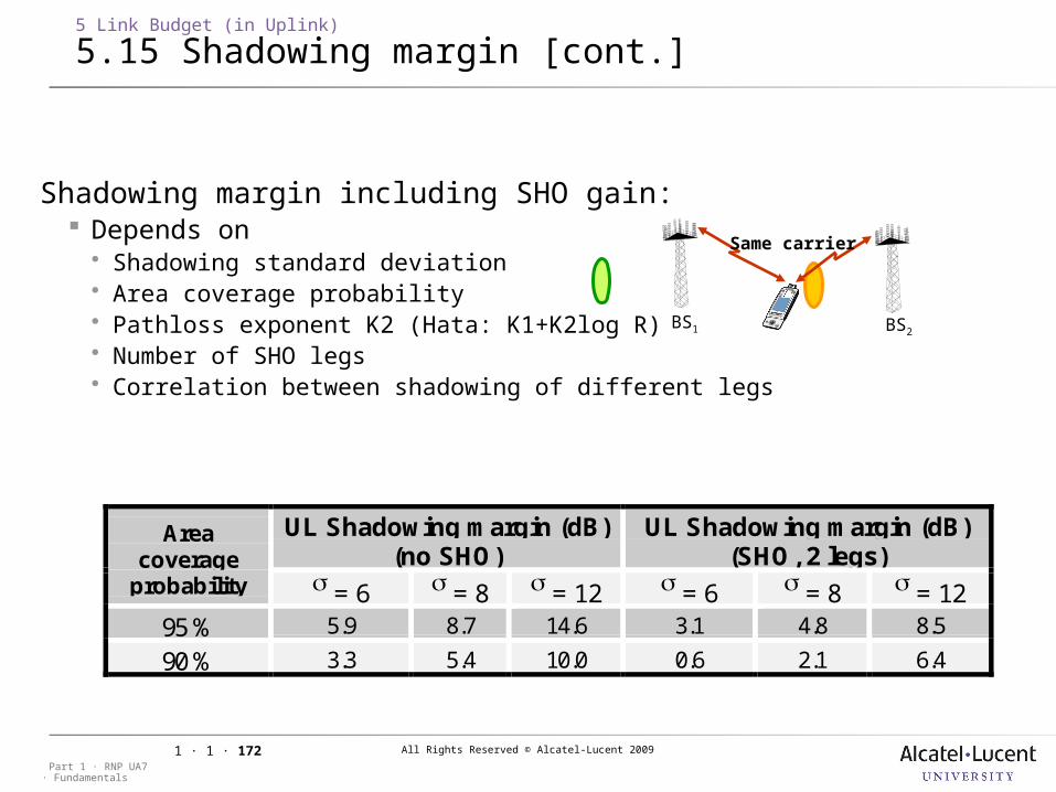
All Rights Reserved © Alcatel-Lucent 2009
· FundamentalsPart 1 · RNP UA7
1 · 1 · 172
Shadowing margin including SHO gain: Depends on Shadowing standard deviation Area coverage probability Pathloss exponent K2 (Hata: K1+K2log R) Number of SHO legs Correlation between shadowing of different legs
UL Shadowing margin (dB)(no SHO)
UL Shadowing margin (dB)(SHO, 2 legs)
Areacoverage
probability = 6 = 8 = 12 = 6 = 8 = 1295 % 5.9 8.7 14.6 3.1 4.8 8.5
90 % 3.3 5.4 10.0 0.6 2.1 6.4
5 Link Budget (in Uplink)
5.15 Shadowing margin [cont.]
BS1 BS2
Same carrier
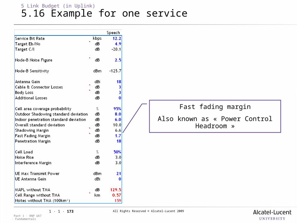
All Rights Reserved © Alcatel-Lucent 2009
· FundamentalsPart 1 · RNP UA7
1 · 1 · 173
5 Link Budget (in Uplink)
5.16 Example for one service
Fast fading margin
Also known as « Power Control Headroom »
All Rights Reserved © Alcatel-Lucent 2009
· FundamentalsPart 1 · RNP UA7
1 · 1 · 174
5 Link Budget (in Uplink)
5.17 Fast fading margin
Fast Fading (Rayleigh) margin Fast fading: Fast fading signal level variations due to multi-paths (with
different delays and amplitudes) Modelled by superposition of mutiple paths with Rayleigh
distribution UMTS Fast Power control: The UMTS system tries to fight against fast fading with fast power
control (every 0.666ms) When the mobile transmits at its maximum power, it will not be
able to compensate for fast fading due to this power limitation Power control is not anymore efficient at cell edge: the
performance at cell edge becomes close to the one without power control
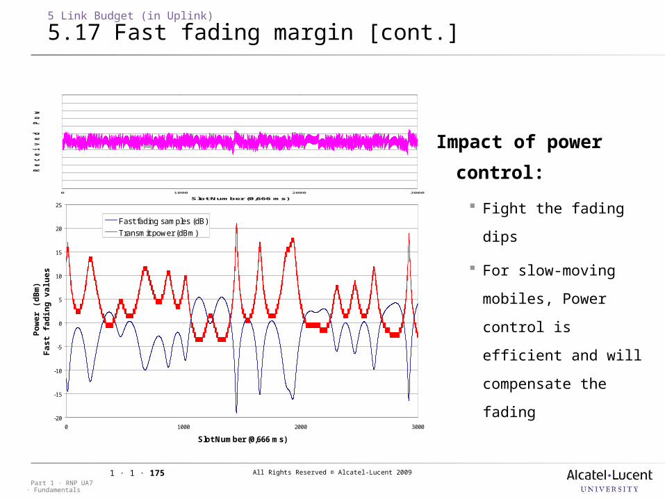
All Rights Reserved © Alcatel-Lucent 2009
· FundamentalsPart 1 · RNP UA7
1 · 1 · 175
Impact of power
control:
Fight the fading dips
For slow-moving
mobiles, Power control
is efficient and will
compensate the fading
-20
-15
-10
-5
0
5
10
15
20
25
0 1000 2000 3000
Slot Number (0,666 ms)
Po
wer
(d
Bm
)F
ast
fad
ing
val
ues
(d
B)
Fast fading samples (dB)
Transmit power (dBm)
0 1000 2000 3000
Slot Number (0,666 ms)
Received
P
ow
er at N
od
e-B
(d
Bm
)
5 Link Budget (in Uplink)
5.17 Fast fading margin [cont.]
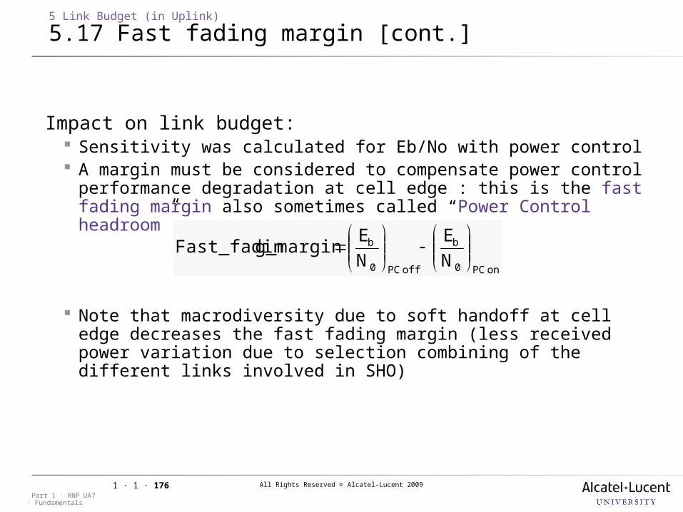
All Rights Reserved © Alcatel-Lucent 2009
· FundamentalsPart 1 · RNP UA7
1 · 1 · 176
5 Link Budget (in Uplink)
5.17 Fast fading margin [cont.]
Impact on link budget: Sensitivity was calculated for Eb/No with power control A margin must be considered to compensate power control
performance degradation at cell edge : this is the fast fading margin also sometimes called “Power Control headroom”
Note that macrodiversity due to soft handoff at cell edge decreases the fast fading margin (less received power variation due to selection combining of the different links involved in SHO)
on PC0
b
off PC0
b
NE
NE
g_marginFast_fadin
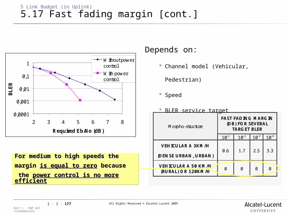
All Rights Reserved © Alcatel-Lucent 2009
· FundamentalsPart 1 · RNP UA7
1 · 1 · 177
For medium to high speeds the For medium to high speeds the
margin margin is equal to zerois equal to zero because because
the the power control is no more power control is no more efficientefficient
For medium to high speeds the For medium to high speeds the
margin margin is equal to zerois equal to zero because because
the the power control is no more power control is no more efficientefficient
FAST FADING MARGIN (DB) FOR SEVERAL
TARGET BLER Morpho-structure
10-1 10-2 10-3 10-4
VEHICULAR A 3KM/H
(DENSE URBAN, URBAN) 0.6 1.7 2.5 3.3
VEHICULAR A 50 KM/H (RURAL) OR 120KM/H
0 0 0 0
Depends on:
Channel model (Vehicular, Pedestrian)
Speed
BLER service target
0,0001
0,001
0,01
0,1
1
2 3 4 5 6 7 8
Required Eb/No (dB)
BL
ER
Without powercontrol
With powercontrol
5 Link Budget (in Uplink)
5.17 Fast fading margin [cont.]
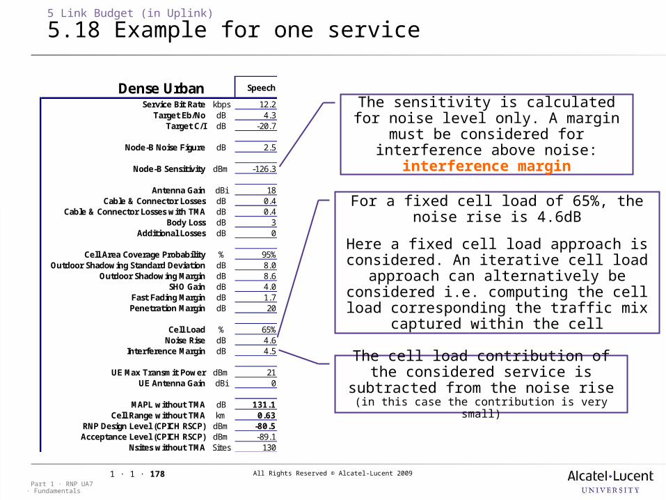
All Rights Reserved © Alcatel-Lucent 2009
· FundamentalsPart 1 · RNP UA7
1 · 1 · 178
5 Link Budget (in Uplink)
5.18 Example for one service
The sensitivity is calculated for noise level only. A margin must be
considered for interference above noise: interference margin
For a fixed cell load of 65%, the noise rise is 4.6dB
Here a fixed cell load approach is considered. An iterative cell load approach
can alternatively be considered i.e. computing the cell load corresponding the
traffic mix captured within the cell
The cell load contribution of the considered service is subtracted from the noise rise (in this case the contribution is
very small)
Dense Urban Speech
Service Bit Rate kbps 12.2Target Eb/No dB 4.3
Target C/I dB -20.7
Node-B Noise Figure dB 2.5
Node-B Sensitivity dBm -126.3
Antenna Gain dBi 18Cable & Connector Losses dB 0.4
Cable & Connector Losses with TMA dB 0.4Body Loss dB 3
Additional Losses dB 0
Cell Area Coverage Probability % 95%Outdoor Shadowing Standard Deviation dB 8.0
Outdoor Shadowing Margin dB 8.6SHO Gain dB 4.0
Fast Fading Margin dB 1.7Penetration Margin dB 20
Cell Load % 65%Noise Rise dB 4.6
Interference Margin dB 4.5
UE Max Transmit Power dBm 21UE Antenna Gain dBi 0
MAPL without TMA dB 131.1Cell Range without TMA km 0.63
RNP Design Level (CPICH RSCP) dBm -80.5Acceptance Level (CPICH RSCP) dBm -89.1
Nsites without TMA Sites 130
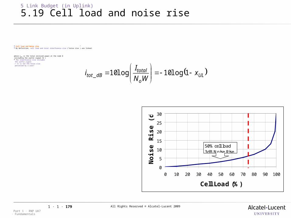
All Rights Reserved © Alcatel-Lucent 2009
· FundamentalsPart 1 · RNP UA7
1 · 1 · 179
Cell load and Noise rise By definition, cell load and total interference rise (“noise rise”) are linked:
where Itotal is the total received power at the node B (including the useful signal Ck ) The interference rise includes the useful signal-> it is not the noise rise perceived by a user!
ULo
totaldBtot x
WNI
i
11010 log log_
5 Link Budget (in Uplink)
5.19 Cell load and noise rise
0
5
10
15
20
25
30
0 10 20 30 40 50 60 70 80 90 100
Cell Load (%)
Nois
e R
ise
(dB
)50% cell load3dB Noise Rise
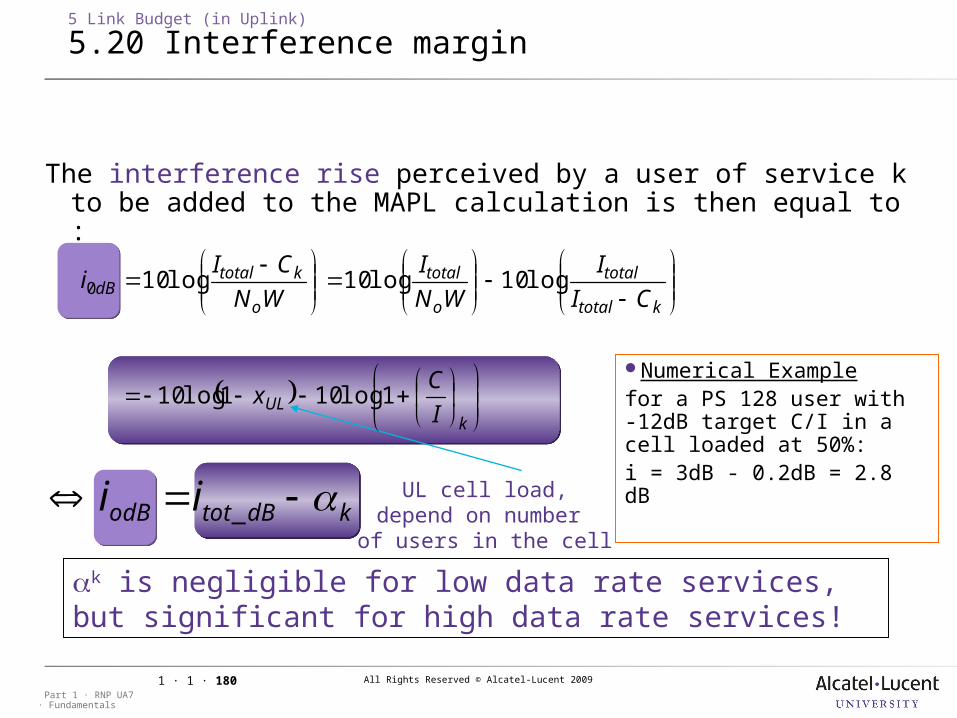
All Rights Reserved © Alcatel-Lucent 2009
· FundamentalsPart 1 · RNP UA7
1 · 1 · 180
The interference rise perceived by a user of service k to be added to the MAPL calculation is then equal to :
kdBtotodB ii _
k is negligible for low data rate services, but significant for high data rate services!
UL cell load,depend on number of users in the cell
5 Link Budget (in Uplink)
5.20 Interference margin
Numerical Examplefor a PS 128 user with -12dB target C/I in a cell loaded at 50%:i = 3dB - 0.2dB = 2.8 dB
kUL
ktotal
total
o
total
o
ktotaldB
IC
x
CII
WNI
WNCI
i
110110
1010100
loglog
logloglog
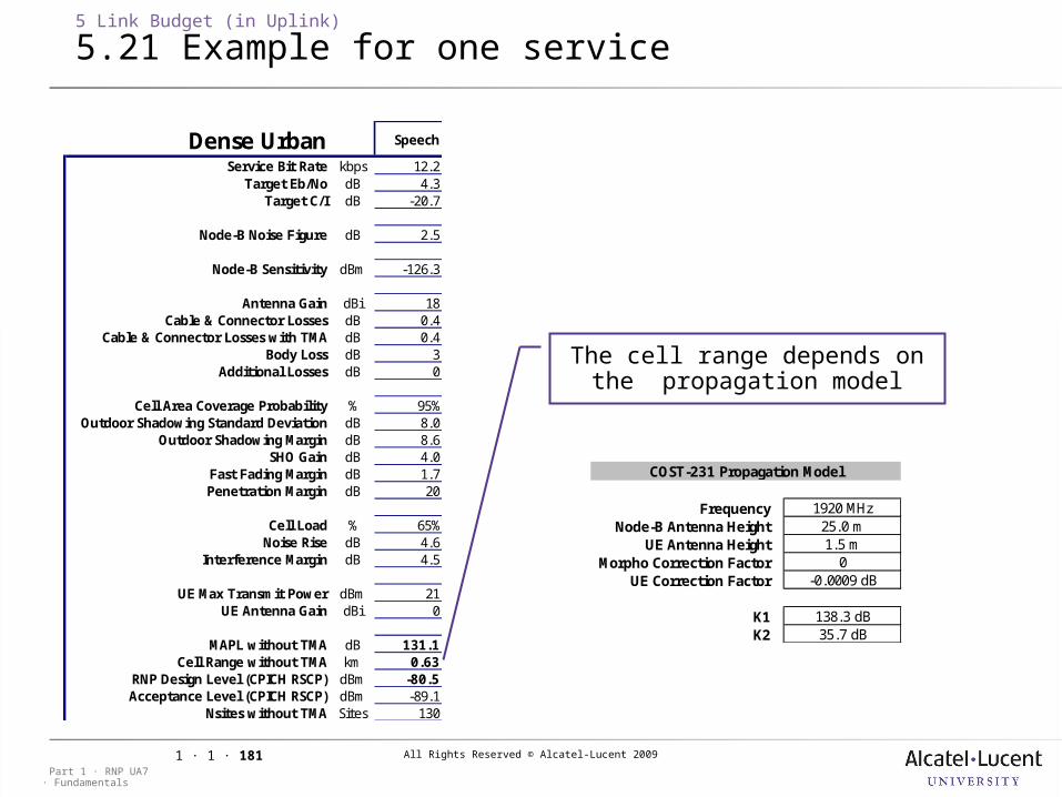
All Rights Reserved © Alcatel-Lucent 2009
· FundamentalsPart 1 · RNP UA7
1 · 1 · 181
5 Link Budget (in Uplink)
5.21 Example for one service
The cell range depends on the propagation model
Dense Urban Speech
Service Bit Rate kbps 12.2Target Eb/No dB 4.3
Target C/I dB -20.7
Node-B Noise Figure dB 2.5
Node-B Sensitivity dBm -126.3
Antenna Gain dBi 18Cable & Connector Losses dB 0.4
Cable & Connector Losses with TMA dB 0.4Body Loss dB 3
Additional Losses dB 0
Cell Area Coverage Probability % 95%Outdoor Shadowing Standard Deviation dB 8.0
Outdoor Shadowing Margin dB 8.6SHO Gain dB 4.0
Fast Fading Margin dB 1.7Penetration Margin dB 20
Cell Load % 65%Noise Rise dB 4.6
Interference Margin dB 4.5
UE Max Transmit Power dBm 21UE Antenna Gain dBi 0
MAPL without TMA dB 131.1Cell Range without TMA km 0.63
RNP Design Level (CPICH RSCP) dBm -80.5Acceptance Level (CPICH RSCP) dBm -89.1
Nsites without TMA Sites 130
FrequencyNode-B Antenna Height
UE Antenna HeightMorpho Correction Factor
UE Correction Factor
K1K2
138.3 dB35.7 dB
COST-231 Propagation Model
1920 MHz25.0 m1.5 m
0-0.0009 dB
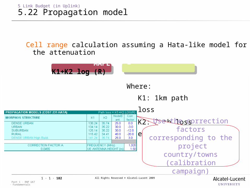
All Rights Reserved © Alcatel-Lucent 2009
· FundamentalsPart 1 · RNP UA7
1 · 1 · 182
5 Link Budget (in Uplink)
5.22 Propagation model
Cell range calculation assuming a Hata-like model for the attenuation
MAPL = K1+K2 log (R)
Where:
K1: 1km path loss
K2: Path loss
exponentUse the correction
factors corresponding to the project country/towns
(calibration campaign)
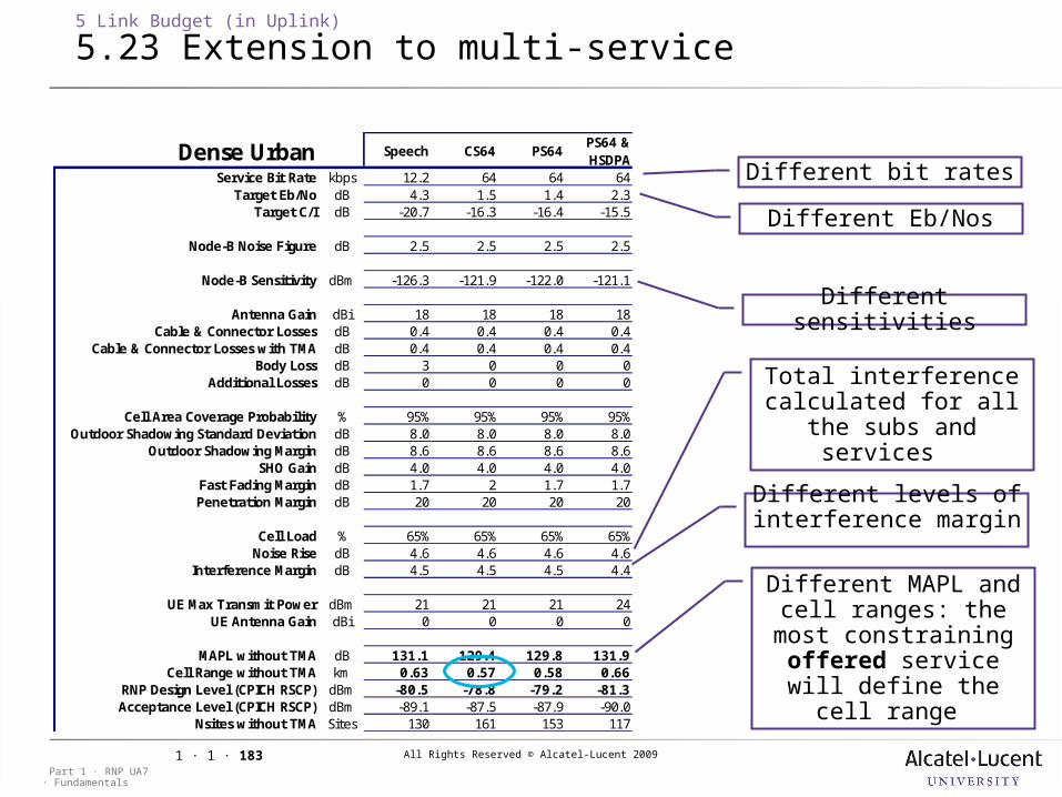
All Rights Reserved © Alcatel-Lucent 2009
· FundamentalsPart 1 · RNP UA7
1 · 1 · 183
5 Link Budget (in Uplink)
5.23 Extension to multi-service
Dense Urban Speech CS64 PS64PS64 & HSDPA
Service Bit Rate kbps 12.2 64 64 64Target Eb/No dB 4.3 1.5 1.4 2.3
Target C/I dB -20.7 -16.3 -16.4 -15.5
Node-B Noise Figure dB 2.5 2.5 2.5 2.5
Node-B Sensitivity dBm -126.3 -121.9 -122.0 -121.1
Antenna Gain dBi 18 18 18 18Cable & Connector Losses dB 0.4 0.4 0.4 0.4
Cable & Connector Losses with TMA dB 0.4 0.4 0.4 0.4Body Loss dB 3 0 0 0
Additional Losses dB 0 0 0 0
Cell Area Coverage Probability % 95% 95% 95% 95%Outdoor Shadowing Standard Deviation dB 8.0 8.0 8.0 8.0
Outdoor Shadowing Margin dB 8.6 8.6 8.6 8.6SHO Gain dB 4.0 4.0 4.0 4.0
Fast Fading Margin dB 1.7 2 1.7 1.7Penetration Margin dB 20 20 20 20
Cell Load % 65% 65% 65% 65%Noise Rise dB 4.6 4.6 4.6 4.6
Interference Margin dB 4.5 4.5 4.5 4.4
UE Max Transmit Power dBm 21 21 21 24UE Antenna Gain dBi 0 0 0 0
MAPL without TMA dB 131.1 129.4 129.8 131.9Cell Range without TMA km 0.63 0.57 0.58 0.66
RNP Design Level (CPICH RSCP) dBm -80.5 -78.8 -79.2 -81.3Acceptance Level (CPICH RSCP) dBm -89.1 -87.5 -87.9 -90.0
Nsites without TMA Sites 130 161 153 117
Different bit rates
Different Eb/Nos
Different sensitivities
Total interference calculated for all the subs and services
Different levels of interference margin
Different MAPL and cell ranges: the most
constraining offered service will define the
cell range
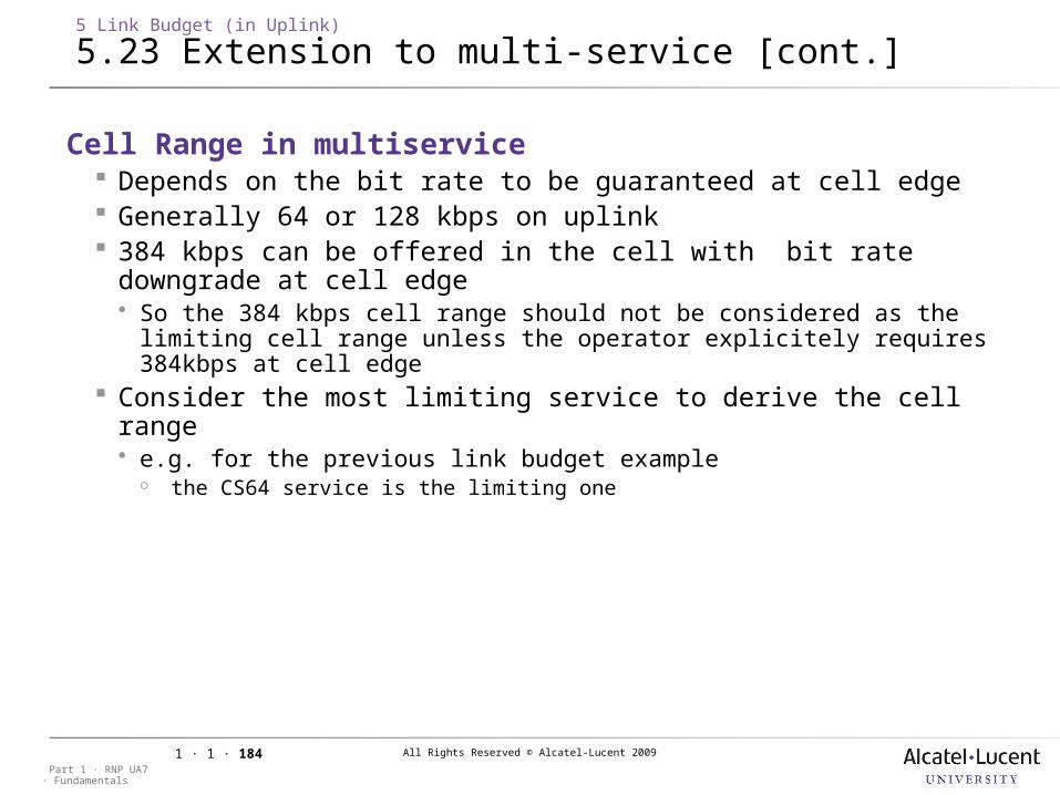
All Rights Reserved © Alcatel-Lucent 2009
· FundamentalsPart 1 · RNP UA7
1 · 1 · 184
5 Link Budget (in Uplink)
5.23 Extension to multi-service [cont.]
Cell Range in multiservice Depends on the bit rate to be guaranteed at cell edge Generally 64 or 128 kbps on uplink 384 kbps can be offered in the cell with bit rate downgrade at cell
edge So the 384 kbps cell range should not be considered as the limiting cell
range unless the operator explicitely requires 384kbps at cell edge Consider the most limiting service to derive the cell range e.g. for the previous link budget example
the CS64 service is the limiting one
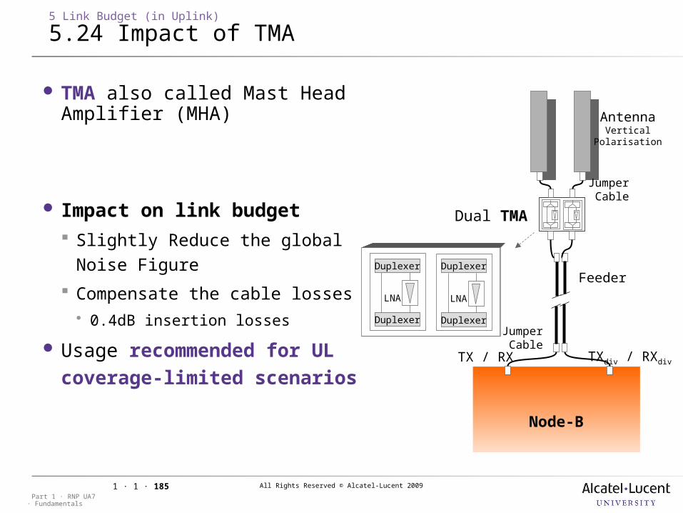
All Rights Reserved © Alcatel-Lucent 2009
· FundamentalsPart 1 · RNP UA7
1 · 1 · 185
5 Link Budget (in Uplink)
5.24 Impact of TMA
TMA also called Mast Head Amplifier (MHA)
Impact on link budget Slightly Reduce the global Noise
Figure
Compensate the cable losses 0.4dB insertion losses
Usage recommended for UL coverage-limited scenarios
Node-B
Dual TMA
Jumper Cable
Jumper Cable
TX / RX TXdiv / RXdiv
Duplexer
Duplexer Duplexer
Duplexer
LNALNA
Feeder
AntennaVertical
Polarisation
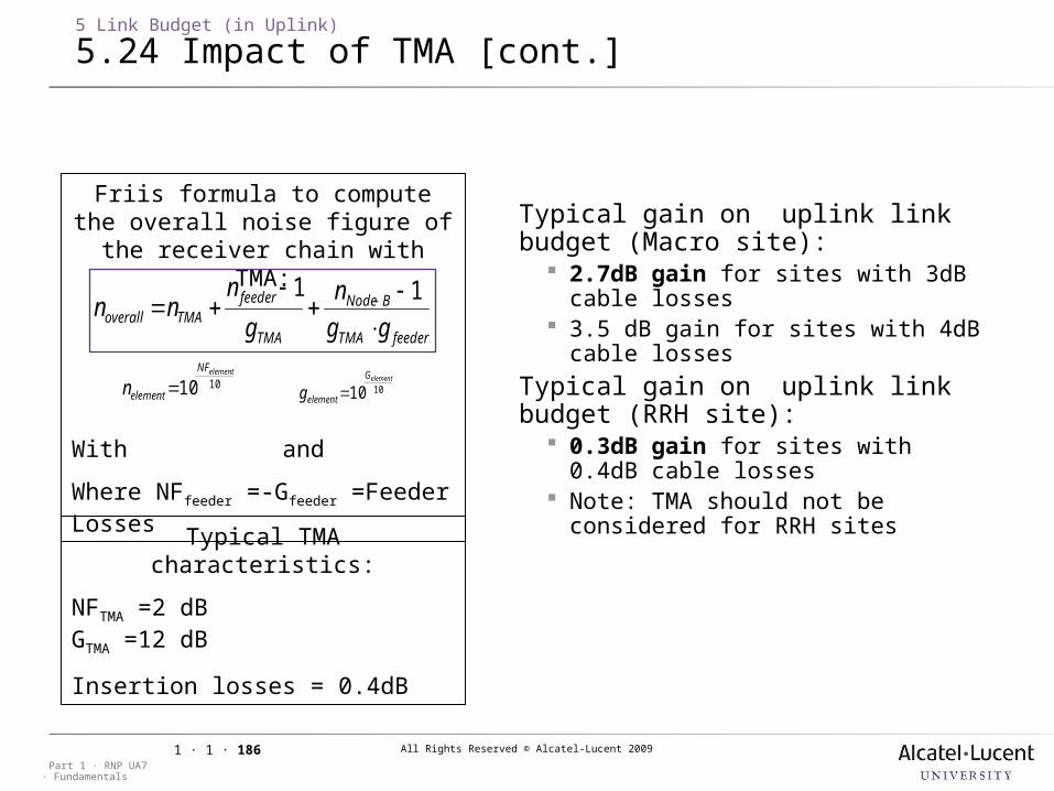
All Rights Reserved © Alcatel-Lucent 2009
· FundamentalsPart 1 · RNP UA7
1 · 1 · 186
5 Link Budget (in Uplink)
5.24 Impact of TMA [cont.]
Friis formula to compute the overall noise figure of the receiver chain with TMA:
With and
Where NFfeeder =-Gfeeder =Feeder Losses
1010elementNF
elementn 1010elementG
elementg
feederTMA
BNode
TMA
feederTMAoverall gg
n
g
nnn
11
Typical TMA characteristics:
NFTMA =2 dB GTMA =12 dB
Insertion losses = 0.4dB
Typical gain on uplink link budget (Macro site): 2.7dB gain for sites with 3dB
cable losses 3.5 dB gain for sites with 4dB
cable losses
Typical gain on uplink link budget (RRH site): 0.3dB gain for sites with 0.4dB
cable losses Note: TMA should not be
considered for RRH sites
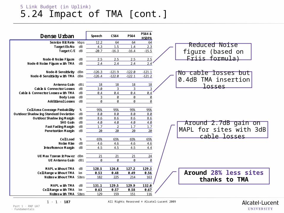
All Rights Reserved © Alcatel-Lucent 2009
· FundamentalsPart 1 · RNP UA7
1 · 1 · 187
5 Link Budget (in Uplink)
5.24 Impact of TMA [cont.]
No cable losses but 0.4dB TMA insertion
losses
Reduced Noise figure (based on Friis formula)
Around 2.7dB gain on MAPL for sites with 3dB cable
losses
Around 28% less sites thanks to TMA
Dense Urban Speech CS64 PS64PS64 & HSDPA
Service Bit Rate kbps 12.2 64 64 64Target Eb/No dB 4.3 1.5 1.4 2.3
Target C/I dB -20.7 -16.3 -16.4 -15.5
Node-B Noise Figure dB 2.5 2.5 2.5 2.5Node-B Noise Figure with TMA dB 2.4 2.4 2.4 2.4
Node-B Sensitivity dBm -126.3 -121.9 -122.0 -121.1Node-B Sensitivity with TMA dBm -126.4 -122.0 -122.1 -121.2
Antenna Gain dBi 18 18 18 18Cable & Connector Losses dB 3.0 3 3 3
Cable & Connector Losses with TMA dB 0.4 0.4 0.4 0.4Body Loss dB 3 0 0 0
Additional Losses dB 0 0 0 0
Cell Area Coverage Probability % 95% 95% 95% 95%Outdoor Shadowing Standard Deviation dB 8.0 8.0 8.0 8.0
Outdoor Shadowing Margin dB 8.6 8.6 8.6 8.6SHO Gain dB 4.0 4.0 4.0 4.0
Fast Fading Margin dB 1.7 2 1.7 1.7Penetration Margin dB 20 20 20 20
Cell Load % 65% 65% 65% 65%Noise Rise dB 4.6 4.6 4.6 4.6
Interference Margin dB 4.5 4.5 4.5 4.4
UE Max Transmit Power dBm 21 21 21 24UE Antenna Gain dBi 0 0 0 0
MAPL without TMA dB 128.5 126.8 127.2 129.3Cell Range without TMA km 0.53 0.48 0.49 0.56
Nsites without TMA Sites 182 225 214 163
MAPL with TMA dB 131.1 129.5 129.9 132.0Cell Range with TMA km 0.63 0.57 0.58 0.67
Nsites with TMA Sites 129 159 151 116
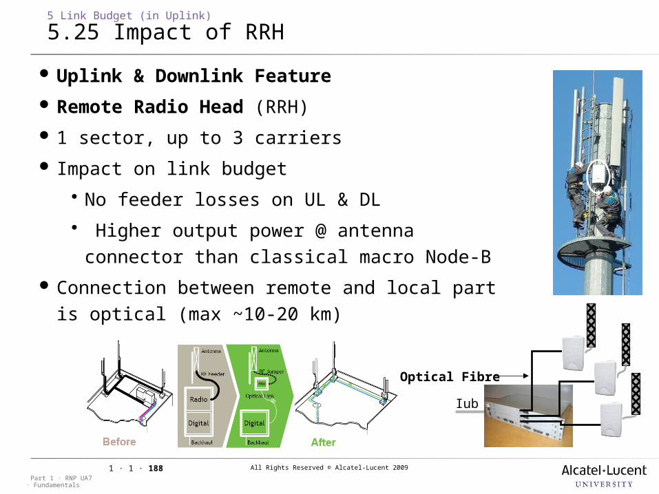
All Rights Reserved © Alcatel-Lucent 2009
· FundamentalsPart 1 · RNP UA7
1 · 1 · 188
Optical Fibre
5 Link Budget (in Uplink)
5.25 Impact of RRH
Iub
Uplink & Downlink Feature
Remote Radio Head (RRH)
1 sector, up to 3 carriers
Impact on link budget
No feeder losses on UL & DL
Higher output power @ antenna connector than classical macro Node-B
Connection between remote and local part is optical (max ~10-20 km)
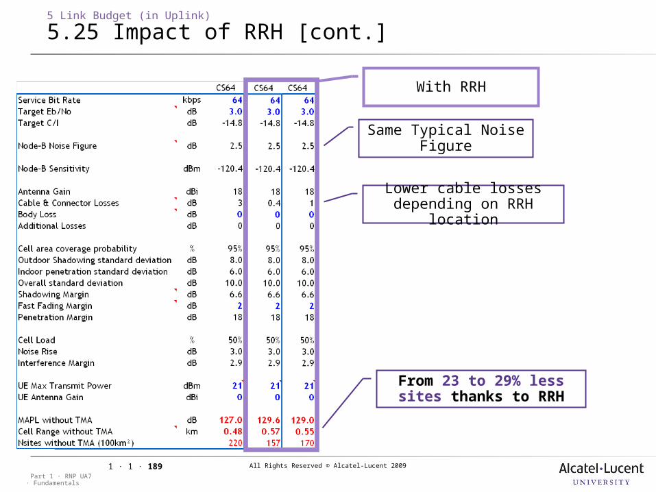
All Rights Reserved © Alcatel-Lucent 2009
· FundamentalsPart 1 · RNP UA7
1 · 1 · 189
5 Link Budget (in Uplink)
5.25 Impact of RRH [cont.]
Same Typical Noise Figure
With RRH
Lower cable losses depending on RRH location
From 23 to 29% less sites thanks to RRH
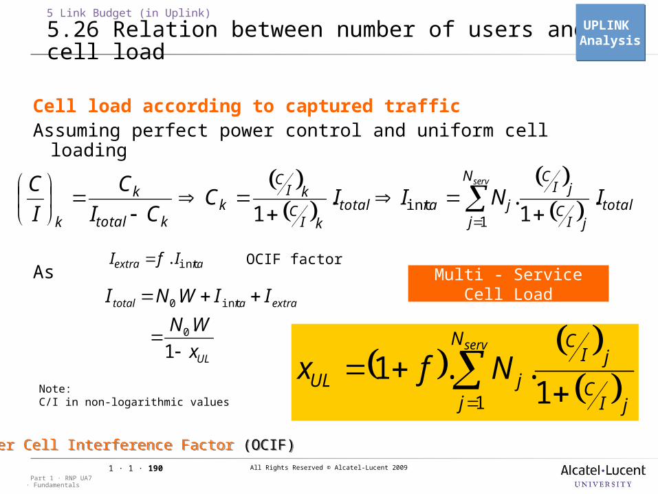
All Rights Reserved © Alcatel-Lucent 2009
· FundamentalsPart 1 · RNP UA7
1 · 1 · 190
Cell load according to captured trafficAssuming perfect power control and uniform cell loading
As
5 Link Budget (in Uplink)
5.26 Relation between number of users and cell load
servN
jtotal
jIC
jIC
jratotalkI
CkI
C
kktotal
k
k
INIICCI
CIC
1 11... int
raextra IfI int.
UL
extraratotal
x
WN
IIWNI
1
.
.
0
int0
servN
j jIC
jIC
jUL Nfx1 1
..1
OCIF factor
Note: C/I in non-logarithmic values
Multi - Service Cell Load
UPLINK AnalysisUPLINK Analysis
Other Cell Interference Factor (OCIF)Other Cell Interference Factor (OCIF)
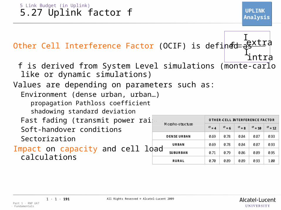
All Rights Reserved © Alcatel-Lucent 2009
· FundamentalsPart 1 · RNP UA7
1 · 1 · 191
Other Cell Interference Factor (OCIF) is defined as
f is derived from System Level simulations (monte-carlo like or dynamic simulations)
Values are depending on parameters such as:Environment (dense urban, urban…)
propagation Pathloss coefficient shadowing standard deviation
Fast fading (transmit power raise)Soft-handover conditionsSectorization
Impact on capacity and cell load calculations
intra
Iextra
I f
5 Link Budget (in Uplink)
5.27 Uplink factor f
OTHER-CELL INTERFERENCE FACTORMorpho-structure
= 4 = 6 = 8 = 10 = 12
DENSE URBAN 0.69 0.78 0.84 0.87 0.93
URBAN 0.69 0.78 0.84 0.87 0.93
SUBURBAN 0.71 0.79 0.86 0.89 0.95
RURAL 0.70 0.89 0.89 0.93 1.00
UPLINK AnalysisUPLINK Analysis
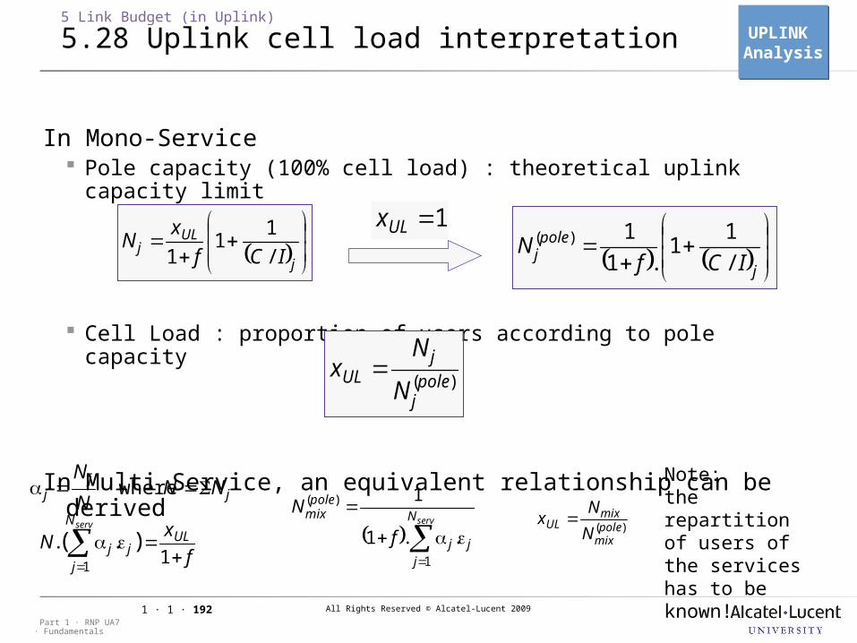
All Rights Reserved © Alcatel-Lucent 2009
· FundamentalsPart 1 · RNP UA7
1 · 1 · 192
In Mono-Service Pole capacity (100% cell load) : theoretical uplink capacity limit
Cell Load : proportion of users according to pole capacity
In Multi Service, an equivalent relationship can be derived
5 Link Budget (in Uplink)
5.28 Uplink cell load interpretation
)(polej
jUL
N
Nx
jj
j NNN
N where
fx
N ULN
jjj
serv
11
)( ..
servN
jjj
polemix
f
N
1
1
1
..
)(
Note:the repartition of users of the services has to be known!
j
ULj ICf
xN
/1
11
j
polej ICf
N/.
)( 11
1
11ULx
)(polemix
mixUL
N
Nx
UPLINK AnalysisUPLINK Analysis
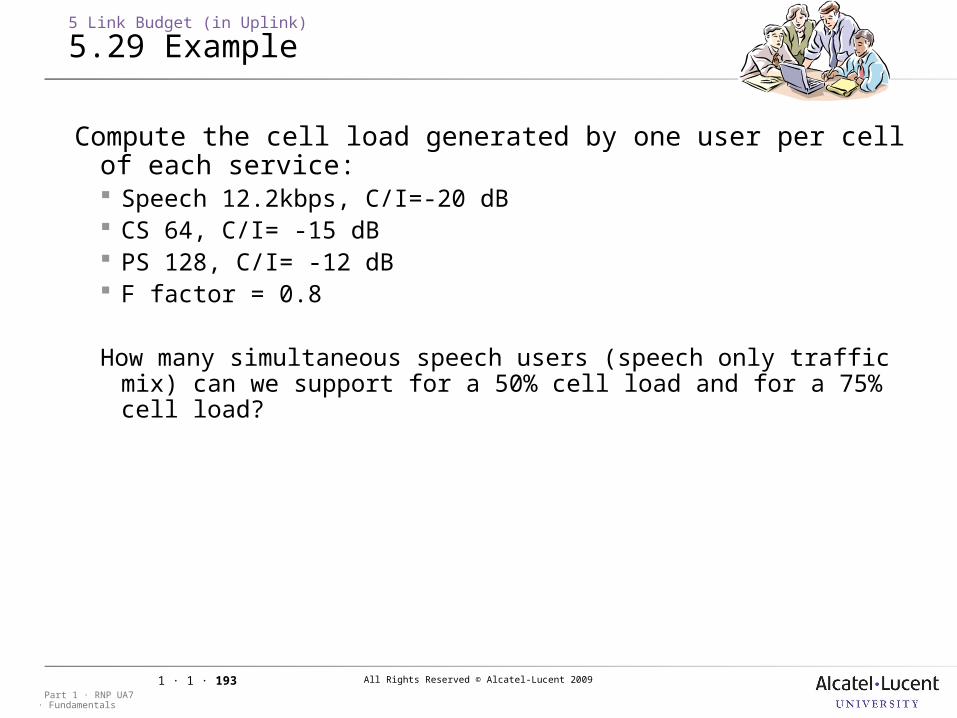
All Rights Reserved © Alcatel-Lucent 2009
· FundamentalsPart 1 · RNP UA7
1 · 1 · 193
5 Link Budget (in Uplink)
5.29 Example
Compute the cell load generated by one user per cell of each service: Speech 12.2kbps, C/I=-20 dB CS 64, C/I= -15 dB PS 128, C/I= -12 dB F factor = 0.8
How many simultaneous speech users (speech only traffic mix) can we support for a 50% cell load and for a 75% cell load?
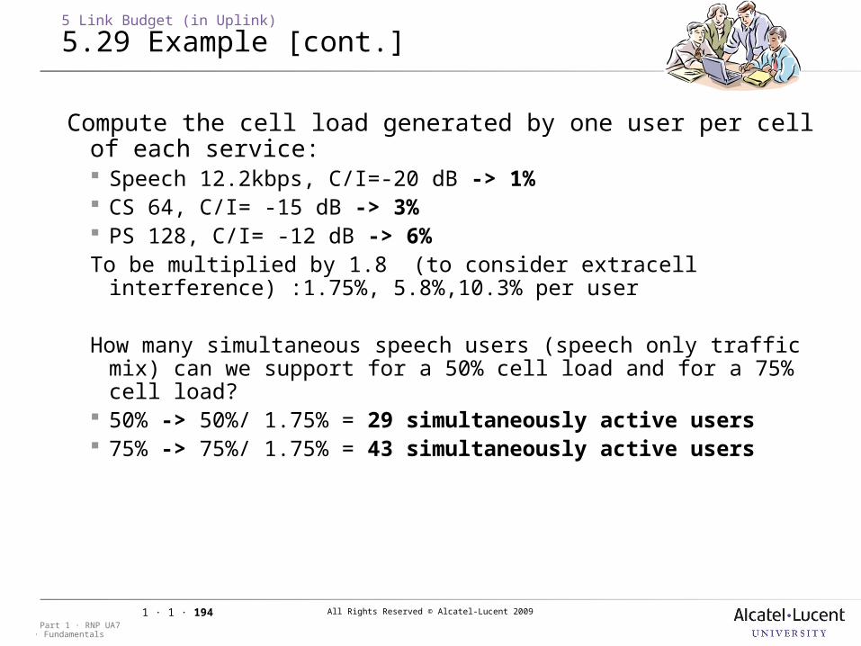
All Rights Reserved © Alcatel-Lucent 2009
· FundamentalsPart 1 · RNP UA7
1 · 1 · 194
5 Link Budget (in Uplink)
5.29 Example [cont.]
Compute the cell load generated by one user per cell of each service: Speech 12.2kbps, C/I=-20 dB -> 1% CS 64, C/I= -15 dB -> 3% PS 128, C/I= -12 dB -> 6%To be multiplied by 1.8 (to consider extracell interference) :1.75%,
5.8%,10.3% per user
How many simultaneous speech users (speech only traffic mix) can we support for a 50% cell load and for a 75% cell load?
50% -> 50%/ 1.75% = 29 simultaneously active users 75% -> 75%/ 1.75% = 43 simultaneously active users
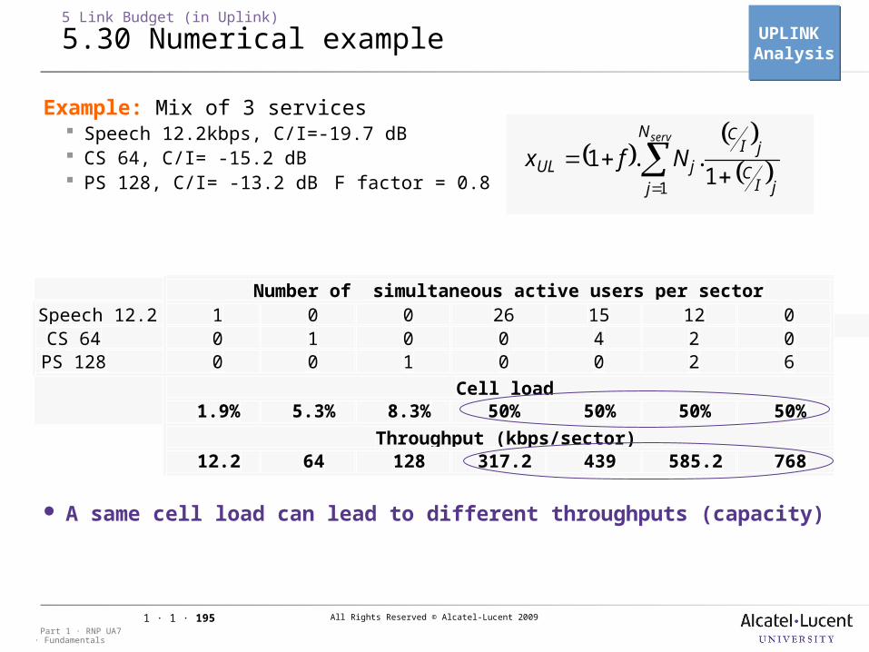
All Rights Reserved © Alcatel-Lucent 2009
· FundamentalsPart 1 · RNP UA7
1 · 1 · 195
Example: Mix of 3 services Speech 12.2kbps, C/I=-19.7 dB CS 64, C/I= -15.2 dB PS 128, C/I= -13.2 dB F factor = 0.8
Different combinations of users lead to the same cell load A same cell load can lead to different throughputs (capacity)
5 Link Budget (in Uplink)
5.30 Numerical example
servN
j jIC
jIC
jUL Nfx1
11 ..
Speech 12.2 1 0 0 26 15 12 0CS 64 0 1 0 0 4 2 0PS 128 0 0 1 0 0 2 6
1.9% 5.3% 8.3% 50% 50% 50% 50%
12.2 64 128 317.2 439 585.2 768
Number of simultaneous active users per sector
Cell load
Throughput (kbps/sector)
UPLINK AnalysisUPLINK Analysis
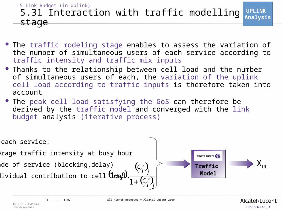
All Rights Reserved © Alcatel-Lucent 2009
· FundamentalsPart 1 · RNP UA7
1 · 1 · 196
5 Link Budget (in Uplink)
5.31 Interaction with traffic modelling stage
The traffic modeling stage enables to assess the variation of the number of simultaneous users of each service according to traffic intensity and traffic mix inputs
Thanks to the relationship between cell load and the number of simultaneous users of each, the variation of the uplink cell load according to traffic inputs is therefore taken into account
The peak cell load satisfying the GoS can therefore be derived by the traffic model and converged with the link budget analysis (iterative process)
XUL
jIC
jIC
f
1
1 .
For each service:
•Average traffic intensity at busy hour
•Grade of service (blocking,delay)
•Individual contribution to cell load
UPLINK AnalysisUPLINK Analysis
Traffic ModelTraffic Model
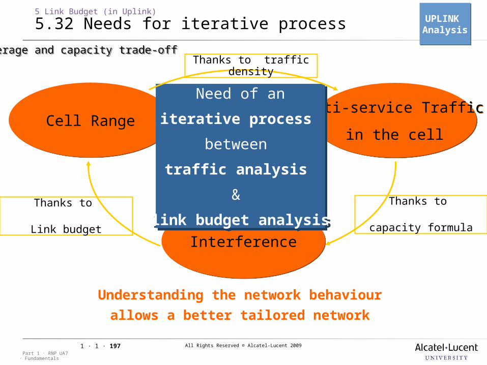
All Rights Reserved © Alcatel-Lucent 2009
· FundamentalsPart 1 · RNP UA7
1 · 1 · 197
5 Link Budget (in Uplink)
5.32 Needs for iterative process
Multi-service Traffic
in the cell
Multi-service Traffic
in the cellCell RangeCell Range
InterferenceInterference
Need of an
iterative process
between
traffic analysis
&
link budget analysis
Need of an
iterative process
between
traffic analysis
&
link budget analysis
Understanding the network behaviour
allows a better tailored network
Thanks to traffic density
Thanks to
capacity formula
Thanks to
Link budget
UPLINK AnalysisUPLINK Analysis
Coverage and capacity trade-offCoverage and capacity trade-off
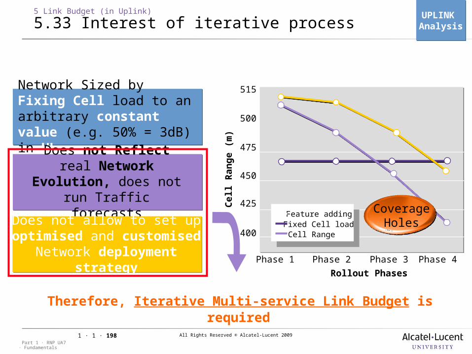
All Rights Reserved © Alcatel-Lucent 2009
· FundamentalsPart 1 · RNP UA7
1 · 1 · 198
5 Link Budget (in Uplink)
5.33 Interest of iterative process
Rollout Phases
Phase 1 Phase 2 Phase 3 Phase 4
515
500
475
450
425
400
Feature addingFixed Cell loadCell Range
Cell R
an
ge (
m)
Network Sized by Fixing Cell load to an arbitrary constant value (e.g. 50% = 3dB) in UL
Does not Reflect real Network Evolution, does not run Traffic
forecastsDoes not allow to set up
optimised and customised Network deployment
strategy
Coverage Holes
Therefore, Iterative Multi-service Link Budget is required
UPLINK AnalysisUPLINK Analysis
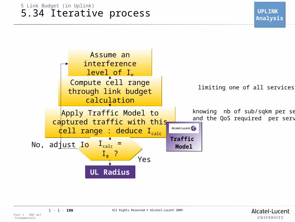
All Rights Reserved © Alcatel-Lucent 2009
· FundamentalsPart 1 · RNP UA7
1 · 1 · 199
5 Link Budget (in Uplink)
5.34 Iterative process
Assume an interference level of
I0
Assume an interference level of
I0Compute cell range through link budget
calculation
Compute cell range through link budget
calculation
Apply Traffic Model to captured traffic with this cell range :
deduce Icalc
Apply Traffic Model to captured traffic with this cell range :
deduce Icalc
Icalc = I0 ?
Icalc = I0 ?
UL RadiusUL Radius
Yes
No, adjust Io
limiting one of all services radii
knowing nb of sub/sqkm per serviceand the QoS required per service
UPLINK AnalysisUPLINK Analysis
Traffic ModelTraffic Model
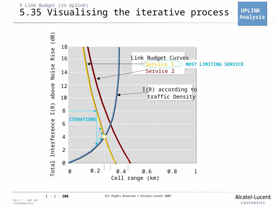
All Rights Reserved © Alcatel-Lucent 2009
· FundamentalsPart 1 · RNP UA7
1 · 1 · 200
0.2 0.60
10
8
6
4
2
0
Tot
al I
nter
fere
nce
I(R
) a
bove
Noi
se R
ise
(d
B)
0.4 0.8 1
12
14
16
18
Link Budget CurvesService 1Service 2
I(R) according to traffic Density
Cell range (km)
5 Link Budget (in Uplink)
5.35 Visualising the iterative process
MOST LIMITING SERVICE
ITERATIONS
UPLINK AnalysisUPLINK Analysis
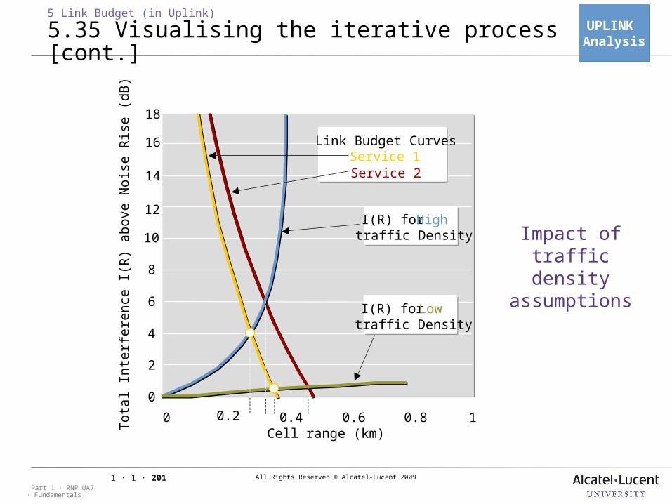
All Rights Reserved © Alcatel-Lucent 2009
· FundamentalsPart 1 · RNP UA7
1 · 1 · 201
5 Link Budget (in Uplink)
5.35 Visualising the iterative process [cont.]
0.2 0.60
10
8
6
4
2
0
Tot
al I
nter
fere
nce
I(R
) a
bove
Noi
se R
ise
(d
B)
0.4 0.8 1
12
14
16
18
Link Budget CurvesService 1Service 2
I(R) for High traffic Density
I(R) for Low traffic Density
Cell range (km)
Impact of traffic density
assumptions
UPLINK AnalysisUPLINK Analysis
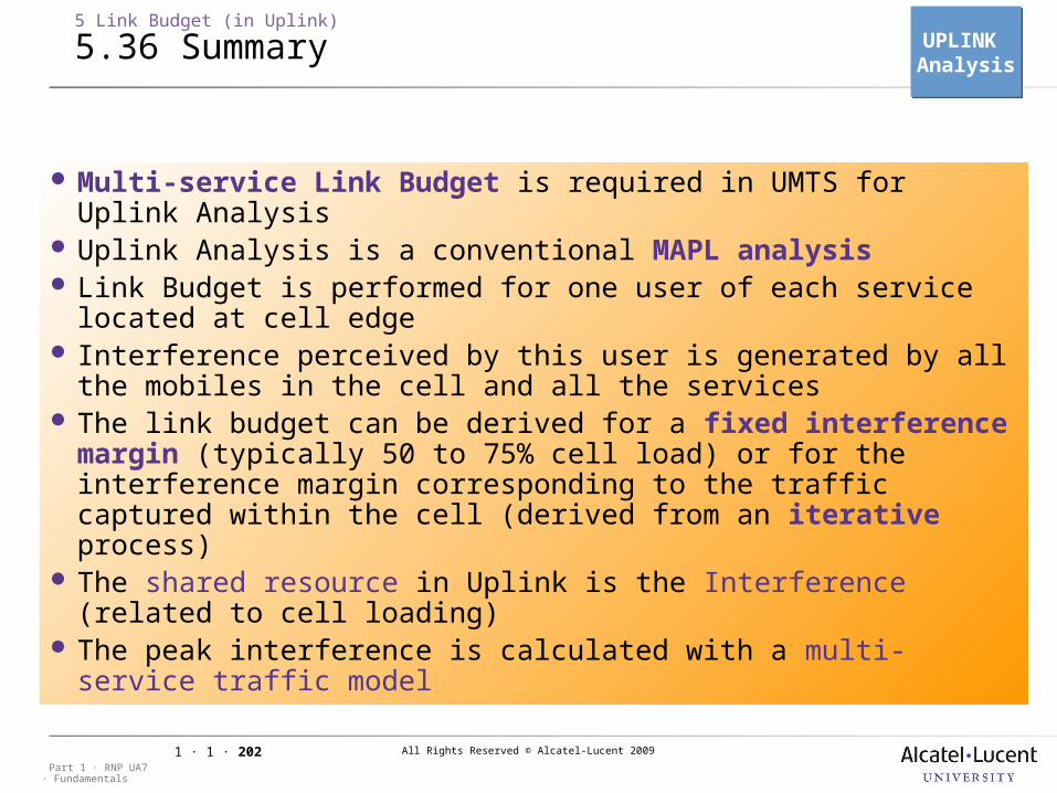
All Rights Reserved © Alcatel-Lucent 2009
· FundamentalsPart 1 · RNP UA7
1 · 1 · 202
Multi-service Link Budget is required in UMTS for Uplink Analysis
Uplink Analysis is a conventional MAPL analysis Link Budget is performed for one user of each service located
at cell edge Interference perceived by this user is generated by all the
mobiles in the cell and all the services The link budget can be derived for a fixed interference
margin (typically 50 to 75% cell load) or for the interference margin corresponding to the traffic captured within the cell (derived from an iterative process)
The shared resource in Uplink is the Interference (related to cell loading)
The peak interference is calculated with a multi-service traffic model
5 Link Budget (in Uplink)
5.36 Summary UPLINK AnalysisUPLINK Analysis
All Rights Reserved © Alcatel-Lucent 2009
· FundamentalsPart 1 · RNP UA7
1 · 1 · 203

All Rights Reserved © Alcatel-Lucent 2009
· FundamentalsPart 1 · RNP UA7
1 · 1 · 204
6 Basic Radio Network Parameter Definition
All Rights Reserved © Alcatel-Lucent 2009
· FundamentalsPart 1 · RNP UA7
1 · 1 · 205
6 Basic Radio Network Parameter Definition
6.1 Session presentation
Objective: to be able to define the basic radio network parameters
(neighborhood planning and code planning parameters)
All Rights Reserved © Alcatel-Lucent 2009
· FundamentalsPart 1 · RNP UA7
1 · 1 · 206
6.1 Session presentation
6.1.1 Neighborhood planning
Objective: to be able to describe the criteria and methods used to perform
neighborhood planning.
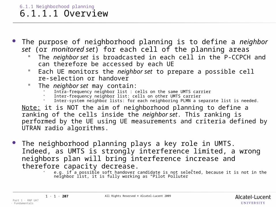
All Rights Reserved © Alcatel-Lucent 2009
· FundamentalsPart 1 · RNP UA7
1 · 1 · 207
6.1.1 Neighborhood planning
6.1.1.1 Overview
The purpose of neighborhood planning is to define a neighbor set (or monitored set) for each cell of the planning areas The neighbor set is broadcasted in each cell in the P-CCPCH and
can therefore be accessed by each UE Each UE monitors the neighbor set to prepare a possible cell re-
selection or handover The neighbor set may contain:
Intra-frequency neighbor list : cells on the same UMTS carrier Inter-frequency neighbor list: cells on other UMTS carrier Inter-system neighbor lists: for each neighboring PLMN a separate list is needed.
Note: it is NOT the aim of neighborhood planning to define a ranking of the cells inside the neighbor set. This ranking is performed by the UE using UE measurements and criteria defined by UTRAN radio algorithms.
The neighborhood planning plays a key role in UMTS. Indeed, as UMTS is strongly interference limited, a wrong neighbors plan will bring interference increase and therefore capacity decrease.
e.g. if a possible soft handover candidate is not selected, because it is not in the neighbor list, it is fully working as “Pilot Polluter”
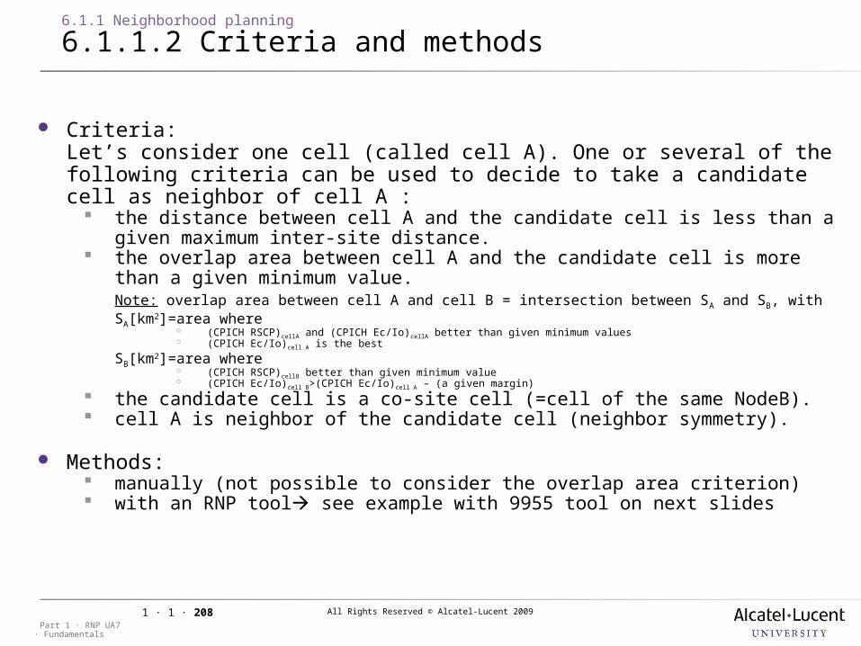
All Rights Reserved © Alcatel-Lucent 2009
· FundamentalsPart 1 · RNP UA7
1 · 1 · 208
6.1.1 Neighborhood planning
6.1.1.2 Criteria and methods
Criteria:Let’s consider one cell (called cell A). One or several of the following criteria can be used to decide to take a candidate cell as neighbor of cell A : the distance between cell A and the candidate cell is less than a
given maximum inter-site distance. the overlap area between cell A and the candidate cell is more
than a given minimum value. Note: overlap area between cell A and cell B = intersection between SA and SB, withSA[km2]=area where
(CPICH RSCP)cellA and (CPICH Ec/Io)cellA better than given minimum values (CPICH Ec/Io)cell A is the best
SB[km2]=area where (CPICH RSCP)cellB better than given minimum value (CPICH Ec/Io)cell B>(CPICH Ec/Io)cell A – (a given margin)
the candidate cell is a co-site cell (=cell of the same NodeB). cell A is neighbor of the candidate cell (neighbor symmetry).
Methods: manually (not possible to consider the overlap area criterion) with an RNP tool see example with 9955 tool on next slides
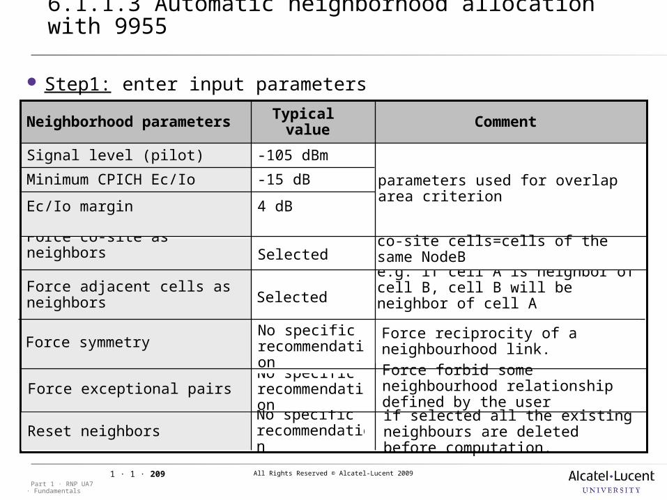
All Rights Reserved © Alcatel-Lucent 2009
· FundamentalsPart 1 · RNP UA7
1 · 1 · 209
No specific recommendation
No specific recommendation
No specific recommendation
6.1.1 Neighborhood planning
6.1.1.3 Automatic neighborhood allocation with 9955
Force symmetry
e.g. if cell A is neighbor of cell B, cell B will be neighbor of cell ASelected
Force adjacent cells as neighbors
co-site cells=cells of the same NodeBSelected
Force co-site as neighbors
parameters used for overlap area criterion
4 dBEc/Io margin
-15 dBMinimum CPICH Ec/Io
-105 dBmSignal level (pilot)
CommentTypical value
Neighborhood parameters
Step1: enter input parameters
Force exceptional pairs
Force reciprocity of a neighbourhood link.Force forbid some neighbourhood relationship defined by the user
Reset neighborsif selected all the existing neighbours are deleted before computation.
All Rights Reserved © Alcatel-Lucent 2009
· FundamentalsPart 1 · RNP UA7
1 · 1 · 210
6.1.1 Neighborhood planning
6.1.1.3 Automatic neighborhood allocation with 9955 [cont.]
Step2: for each cell, 9955 RNP tool calculates the neighbor list as follows if “Force co-site cells as neighbors=Yes”, co-sites cells are taken first
in the neighbor list. cells which fulfill the following criteria are taken in the neighbor list: the maximum inter-site distance criterion the overlap area criterionNote: if the maximum number of neighbors in the list is exceeded, only the
cells with the largest overlap area are kept. if “Force neighbor symmetry”=Yes, cells with a neighbor symmetry
are taken in the neighbor list, under the condition that the maximum number of neighbors has not already been exceeded.
All Rights Reserved © Alcatel-Lucent 2009
· FundamentalsPart 1 · RNP UA7
1 · 1 · 211
6.1 Session presentation
6.1.2 Scrambling code planning
Objective: to be able to describe the criteria and the methods used to
perform the scrambling code planning
All Rights Reserved © Alcatel-Lucent 2009
· FundamentalsPart 1 · RNP UA7
1 · 1 · 212
Scrambling code planning in UMTS FDD is similar to frequency planning in GSM. However it is not such a key performance factor:
it concerns only DL scrambling code (channelization codes and UL scrambling codes are automatically assigned by the RNC)
In contrast to frequency planning, it is not crucial which scrambling codes are allocated to neighbors as long as they are not the same code.
6.1.2 Scrambling code planning
6.1.2.1 Overview
All Rights Reserved © Alcatel-Lucent 2009
· FundamentalsPart 1 · RNP UA7
1 · 1 · 213
DL scrambling codes: used to separate cells restricted to 512 (primary) scrambling codes (easy planning)
Criteria: the reuse distance between two cells using the same scrambling
code inside one frequency shall be higher than 4 x inter-site distance
(preferable) the same scrambling code should not be used in two cells of the same sector
Methods manually with a RNP tool (see see example with 9955 tool on next slide)
6.1.2 Scrambling code planning
6.1.2.2 DL scrambling code planning
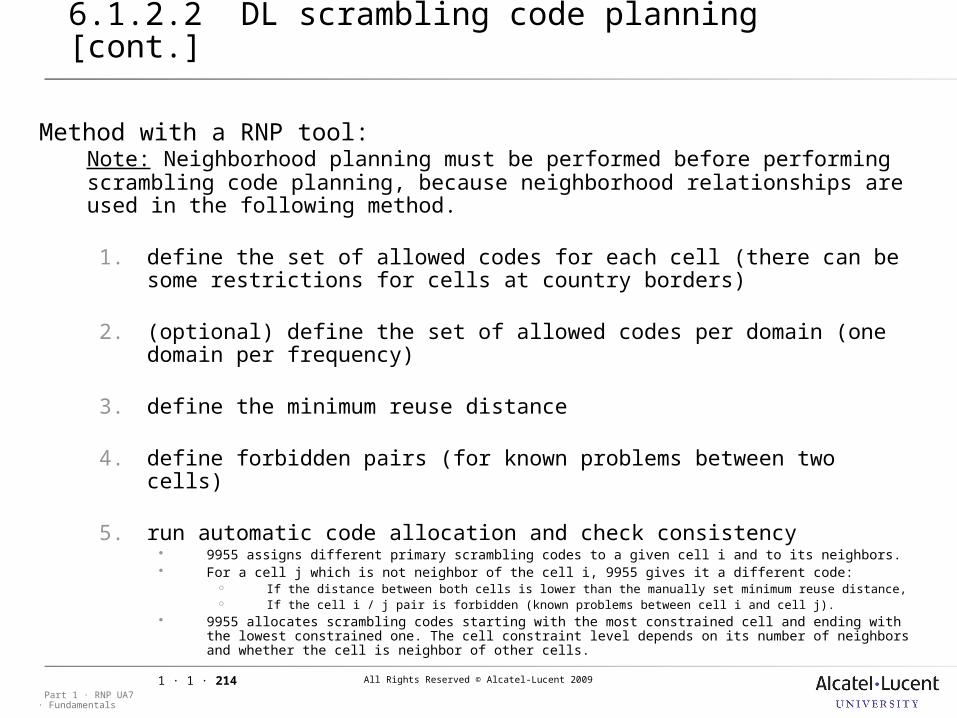
All Rights Reserved © Alcatel-Lucent 2009
· FundamentalsPart 1 · RNP UA7
1 · 1 · 214
Method with a RNP tool:Note: Neighborhood planning must be performed before performing scrambling code planning, because neighborhood relationships are used in the following method.
1. define the set of allowed codes for each cell (there can be some restrictions for cells at country borders)
2. (optional) define the set of allowed codes per domain (one domain per frequency)
3. define the minimum reuse distance
4. define forbidden pairs (for known problems between two cells)
5. run automatic code allocation and check consistency 9955 assigns different primary scrambling codes to a given cell i and to its neighbors. For a cell j which is not neighbor of the cell i, 9955 gives it a different code:
If the distance between both cells is lower than the manually set minimum reuse distance, If the cell i / j pair is forbidden (known problems between cell i and cell j).
9955 allocates scrambling codes starting with the most constrained cell and ending with the lowest constrained one. The cell constraint level depends on its number of neighbors and whether the cell is neighbor of other cells.
6.1.2 Scrambling code planning
6.1.2.2 DL scrambling code planning [cont.]
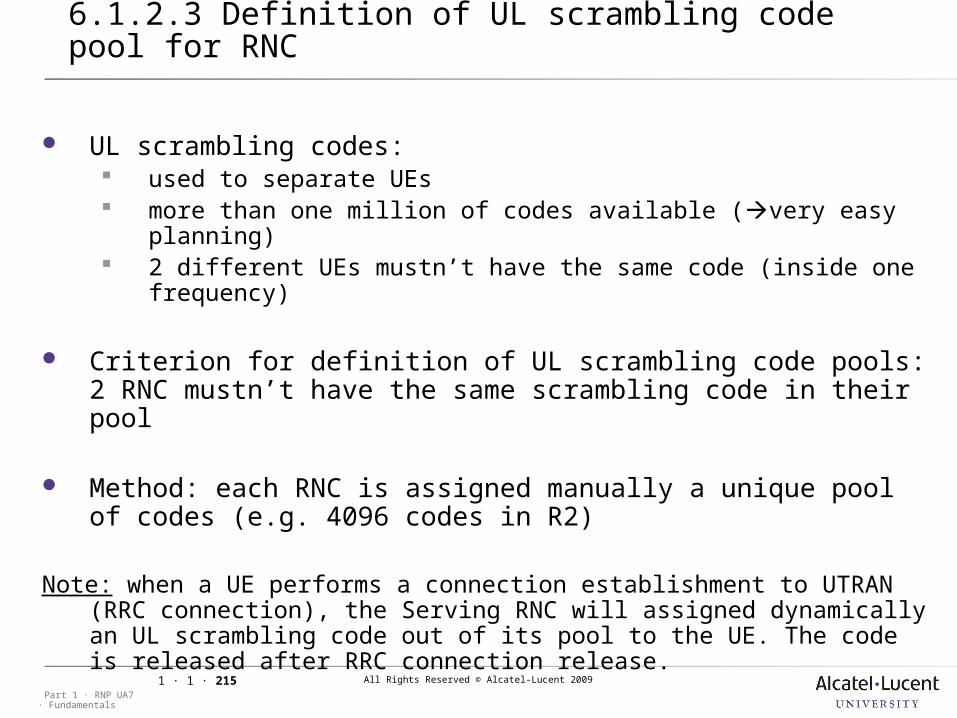
All Rights Reserved © Alcatel-Lucent 2009
· FundamentalsPart 1 · RNP UA7
1 · 1 · 215
6.1.2 Scrambling code planning
6.1.2.3 Definition of UL scrambling code pool for RNC
UL scrambling codes: used to separate UEs more than one million of codes available (very easy planning) 2 different UEs mustn’t have the same code (inside one
frequency)
Criterion for definition of UL scrambling code pools: 2 RNC mustn’t have the same scrambling code in their pool
Method: each RNC is assigned manually a unique pool of codes (e.g. 4096 codes in R2)
Note: when a UE performs a connection establishment to UTRAN (RRC connection), the Serving RNC will assigned dynamically an UL scrambling code out of its pool to the UE. The code is released after RRC connection release.
All Rights Reserved © Alcatel-Lucent 2009
· FundamentalsPart 1 · RNP UA7
1 · 1 · 216
7 Deltas and Modifications
All Rights Reserved © Alcatel-Lucent 2009
· FundamentalsPart 1 · RNP UA7
1 · 1 · 217
7 Deltas and Modifications
7.1 Session presentation
Objective: to be able to distinguish between planning
parameters of different software releases.
All Rights Reserved © Alcatel-Lucent 2009
· FundamentalsPart 1 · RNP UA7
1 · 1 · 218
7.1 Session presentation
7.1.1 Delta UA5.x – UA6 - UA7
Objective: Differences between software releases UA5.x, UA6 and
UA7
All Rights Reserved © Alcatel-Lucent 2009
· FundamentalsPart 1 · RNP UA7
1 · 1 · 219
7.1.1 Delta UA5.x – UA6 - UA7
7.1.1.1 mac-d PDU size management
In UA5.1, the flag to restrict primary cell to 336 bits was was MaxCellRadius
(isHsdpaCellHighPerformance in UA6.0).
Basically, in UA5.1, the mac-d PDU size does not change during the call whatever the configuration of the primary cell. The difference between UA5.1 and UA6.0 is the possibility to reconfigure the mac-d PDU size during the call. This reconfiguration is allowed in UA6.0 if the flag isHighPerformancePduSizeReconfAllowed is set to True.
All Rights Reserved © Alcatel-Lucent 2009
· FundamentalsPart 1 · RNP UA7
1 · 1 · 220
7.1.1 Delta UA5.x – UA6 - UA7
7.1.1.2 CQI adjustement according to Bler
In UA5.0, the purpose of the feature “HSDPA performance enhancements –Configurable CQI adjustment according to BLER target algorithm” is to put the parameters of this algorithm at the OMC-B so that the operator can tune its BLER target.
In UA6.0, the algorithm of CQI adlustement according to Bler is further enhanced by supporting multiple BLER targets (configurable via OMC-B) and auto selection of one of these targets depending upon the average CQI and the UE speed.
All Rights Reserved © Alcatel-Lucent 2009
· FundamentalsPart 1 · RNP UA7
1 · 1 · 221
7.1.1 Delta UA5.x – UA6 - UA7
7.1.1.3 HSDPA OCNS
HSDPA OCNS PRINCIPLE OCNS for HSDPA (HSDPA-OCNS) simulates virtual HSDPA users on the air interface. The main purpose of HSDPA-OCNS is to create load in the HSDPA scheduler that will assign resources for virtual (OCNS) users, and therefore will need to schedule these virtual users together with the real users. Namely load on both HSDPA scheduler and air interface transmit power can be generated by HSDPA- OCNS. This HSDPA-OCNS functionality would be of use in lab testing for measurements and optimization when testing the HSDPA scheduler with real users, particularly when there are limited HSDPA test terminals.
An HSDPA-OCNS setup can be requested by an operator from an user interface in OMC-R WIPS in a similar way as in R99 OCNS. The request is passed to RNC, which then replay it to Node B and the scheduler will finally assign resources for the virtual users in HSPDA-OCNS.
OCNS Orthogonal Code Noise SimulatorOCNS Orthogonal Code Noise Simulator
All Rights Reserved © Alcatel-Lucent 2009
· FundamentalsPart 1 · RNP UA7
1 · 1 · 222
7.1.1 Delta UA5.x – UA6 - UA7
7.1.1.4 ActivityFactorCch
In UA5.0, ActivityFactorCch is hard coded to 66%.
In UA6.0, ActivityFactorCch is defined by the parameter activityFactorCcch.
All Rights Reserved © Alcatel-Lucent 2009
· FundamentalsPart 1 · RNP UA7
1 · 1 · 223
7.1.1 Delta UA5.x – UA6 - UA7
7.1.1.5 Management of UL power profile for HSDPA calls
In UA5.1, the management of UL power profile (lower bound for UL SIR Target) for HSDPA calls was handled by UA5.1.2 “High quality UL R99 RAB for High HSDPA DL data rate” feature.
In UA6, the management of UL power profile (initial value, lower bound and upper bound for UL SIR Target) for HSDPA calls is handled by “Management of UL power profiles depending on whether HSDPA is mapped on the DL” sub-feature of UA6 34246 “Power Control Enhancements” feature. “Management of UL power profiles…” sub-feature of UA6 includes all the functionalities of UA5.1 regarding the upper bound for UL SIR Target, and introduces the same concept for the initial value and the lower bound
All Rights Reserved © Alcatel-Lucent 2009
· FundamentalsPart 1 · RNP UA7
1 · 1 · 224
7.1.1 Delta UA5.x – UA6 - UA7
7.1.1.6 M-BBU Support
In UA6.0, up to 4 M-BBU per xCEM board are possible. An xCEM supports only M-BBU type starting with this release (UA6.0).
Previous UA5.1 configurations based on D/H/E-BBUs are no more supported for the xCEM in UA6.0.
For details in UA5.1 configuration and capacity figures, please see the appropriate version of this document (UA5.1 version).
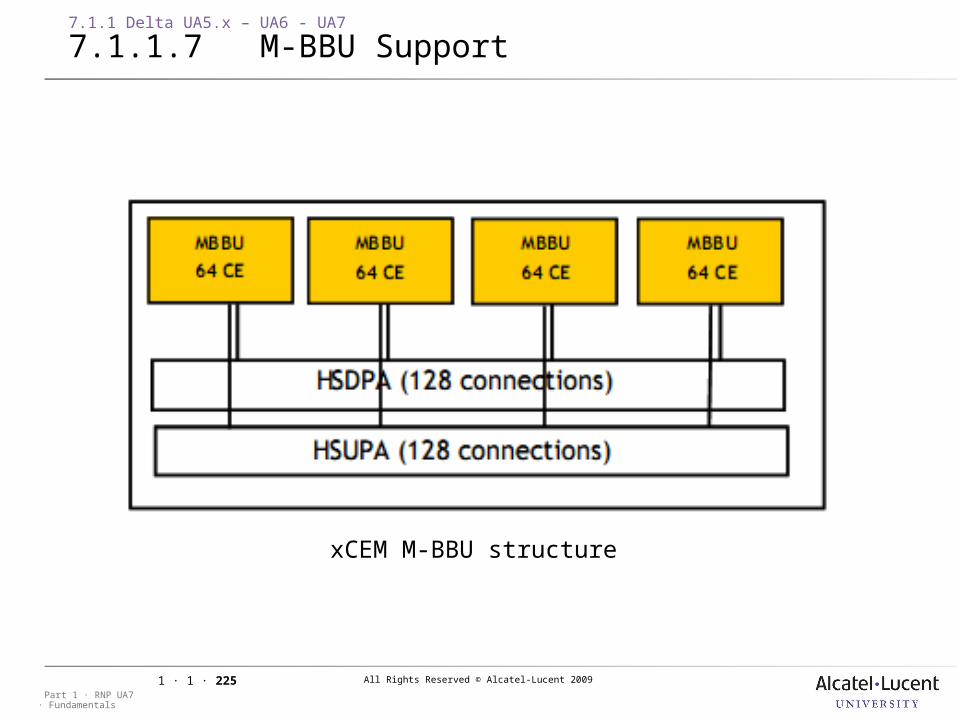
All Rights Reserved © Alcatel-Lucent 2009
· FundamentalsPart 1 · RNP UA7
1 · 1 · 225
7.1.1 Delta UA5.x – UA6 - UA7
7.1.1.7 M-BBU Support
xCEM M-BBU structure
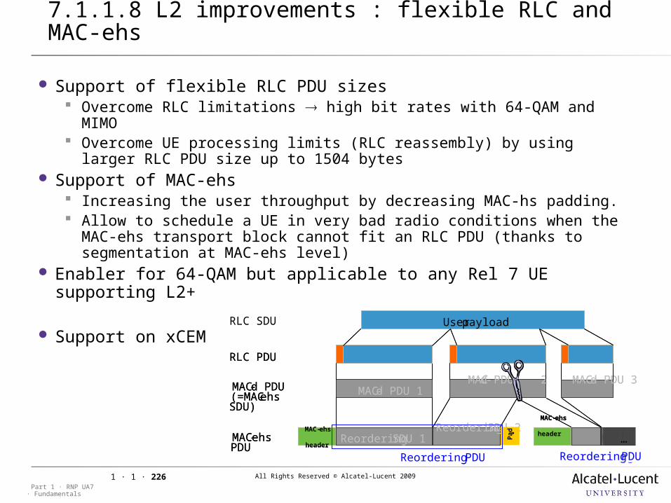
All Rights Reserved © Alcatel-Lucent 2009
· FundamentalsPart 1 · RNP UA7
1 · 1 · 226
7.1.1 Delta UA5.x – UA6 - UA7
7.1.1.8 L2 improvements : flexible RLC and MAC-ehs
Support of flexible RLC PDU sizes Overcome RLC limitations high bit rates with 64-QAM and MIMO Overcome UE processing limits (RLC reassembly) by using larger RLC
PDU size up to 1504 bytes Support of MAC-ehs
Increasing the user throughput by decreasing MAC-hs padding. Allow to schedule a UE in very bad radio conditions when the MAC-ehs
transport block cannot fit an RLC PDU (thanks to segmentation at MAC-ehs level)
Enabler for 64-QAM but applicable to any Rel 7 UE supporting L2+
Support on xCEMUser payloadRLC SDU
RLC PDU
MAC-d PDU (=MAC-ehsSDU)
MAC-d PDU 1MAC-d PDU 2 MAC-d PDU 3
MAC-ehsPDU
MAC-ehs
headerReorderingSDU 1
ReorderingSDU 2
Pad .
MAC-ehs
headerUser payloadRLC SDU
RLC PDU
MAC-d PDU (=MAC-ehsSDU)
MAC-d PDU 1MAC-d PDU 2 MAC-d PDU 3
MAC-ehsPDU
MAC-ehs
headerReordering SDU 1
Reordering SDU 2
Pad.
MAC-ehs
header …
Reordering PDU Reordering PDU
User payloadRLC SDU
RLC PDU
MAC-d PDU (=MAC-ehsSDU)
MAC-d PDU 1MAC-d PDU 2 MAC-d PDU 3
MAC-ehsPDU
MAC-ehs
headerReordering SDU 1
Reordering SDU 2
Pad.
MAC-ehs
header …
Reordering PDU Reordering PDU…
ReorderingPDU ReorderingPDU
User payloadRLC SDU
RLC PDU
MAC-d PDU (=MAC-ehsSDU)
MAC-d PDU 1MAC-d PDU 2 MAC-d PDU 3
MAC-ehsPDU
MAC-ehs
headerReorderingSDU 1
ReorderingSDU 2
Pad .
MAC-ehs
headerUser payloadRLC SDU
RLC PDU
MAC-d PDU (=MAC-ehsSDU)
MAC-d PDU 1MAC-d PDU 2 MAC-d PDU 3
MAC-ehsPDU
MAC-ehs
headerReordering SDU 1
Reordering SDU 2
Pad.
MAC-ehs
header …
Reordering PDU Reordering PDU
User payloadRLC SDU
RLC PDU
MAC-d PDU (=MAC-ehsSDU)
MAC-d PDU 1MAC-d PDU 2 MAC-d PDU 3
MAC-ehsPDU
MAC-ehs
headerReordering SDU 1
Reordering SDU 2
Pad.
MAC-ehs
header …
Reordering PDU Reordering PDU…
Reordering PDU Reordering PDU
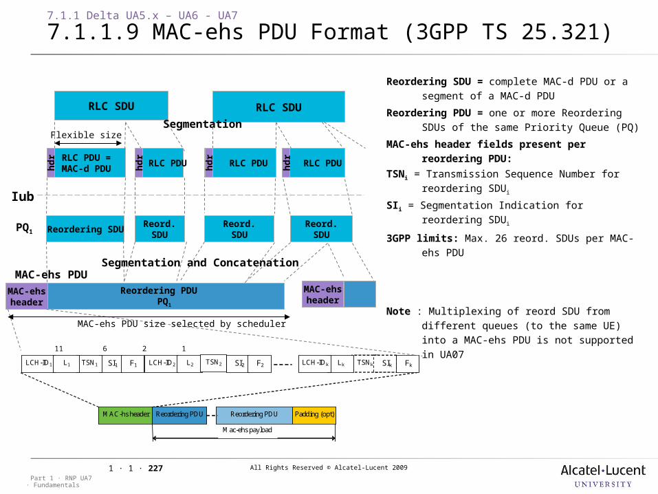
All Rights Reserved © Alcatel-Lucent 2009
· FundamentalsPart 1 · RNP UA7
1 · 1 · 227
7.1.1 Delta UA5.x – UA6 - UA7
7.1.1.9 MAC-ehs PDU Format (3GPP TS 25.321)
RLC SDU
Reordering PDU PQ1
MAC-ehsheader
RLC PDU =MAC-d PDU
RLC SDU
SI1 LCH-ID1
TSN1 L1
MAC-hs header Reordering PDU Padding (opt) Reordering PDU
Mac-ehs payload
TSNk Lk LCH-IDk
SIk F1 Fk SI2 LCH-ID2
L2 F2 TSN2
Reordering SDU = complete MAC-d PDU or a segment of a MAC-d PDU
Reordering PDU = one or more Reordering SDUs of the same Priority Queue (PQ)
MAC-ehs header fields present per reordering PDU:
TSNi = Transmission Sequence Number for reordering SDUi
SIi = Segmentation Indication for reordering SDUi
3GPP limits: Max. 26 reord. SDUs per MAC-ehs PDU
Note : Multiplexing of reord SDU from different queues (to the same UE) into a MAC-ehs PDU is not supported in UA07
Reordering SDUReord.SDU
Reord.SDU
Iub
PQ1
hd
r
RLC PDU RLC PDU RLC PDU
Flexible size
Reord.SDU
MAC-ehs PDU
hd
r
hd
r
hd
r
Segmentation
Segmentation and Concatenation
#bits: 4 11 6 2 1
MAC-ehs PDU size selected by scheduler
MAC-ehsheader
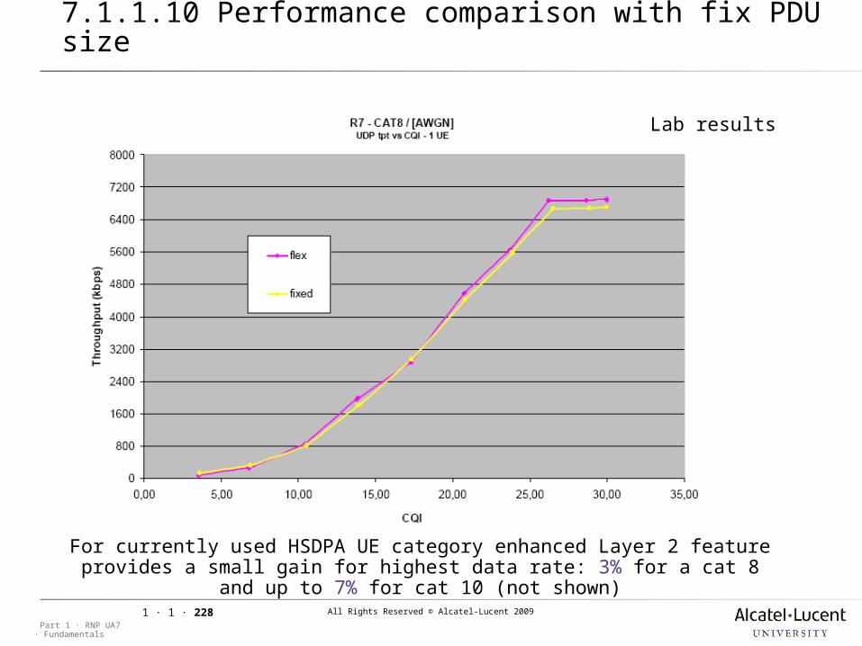
All Rights Reserved © Alcatel-Lucent 2009
· FundamentalsPart 1 · RNP UA7
1 · 1 · 228
7.1.1 Delta UA5.x – UA6 - UA7
7.1.1.10 Performance comparison with fix PDU size
For currently used HSDPA UE category enhanced Layer 2 feature provides a small gain for highest data rate: 3% for a cat 8 and up to 7% for cat 10
(not shown)
Lab results
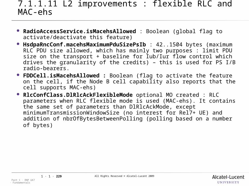
All Rights Reserved © Alcatel-Lucent 2009
· FundamentalsPart 1 · RNP UA7
1 · 1 · 229
7.1.1 Delta UA5.x – UA6 - UA7
7.1.1.11 L2 improvements : flexible RLC and MAC-ehs
RadioAccessService.isMacehsAllowed : Boolean (global flag to activate/deactivate this feature)
HsdpaRncConf.macehsMaximumPduSizePsIb : 42..1504 bytes (maximum RLC PDU size allowed, which has mainly two purposes : limit PDU size on the transport + baseline for Iub/Iur flow control which drives the granularity of the credits) – this is used for PS I/B radio-bearers.
FDDCell.isMacehsAllowed : Boolean (flag to activate the feature on the cell, if the Node B cell capability also reports that the cell supports MAC-ehs)
RlcConfClass.DlRlcAckFlexibleMode optional MO created : RLC parameters when RLC flexible mode is used (MAC-ehs). It contains the same set of parameters than DlRlcAckMode, except minimumTransmissionWindowSize (no interest for Rel7+ UE) and addition of nbrOfBytesBetweenPolling (polling based on a number of bytes)
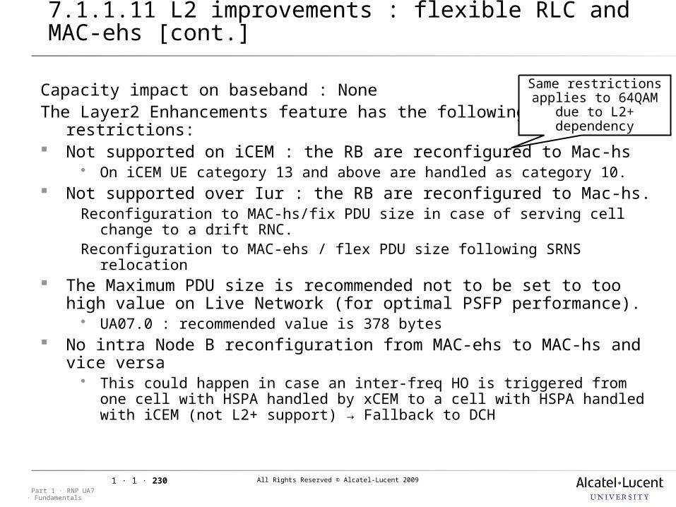
All Rights Reserved © Alcatel-Lucent 2009
· FundamentalsPart 1 · RNP UA7
1 · 1 · 230
7.1.1 Delta UA5.x – UA6 - UA7
7.1.1.11 L2 improvements : flexible RLC and MAC-ehs [cont.]
Capacity impact on baseband : NoneThe Layer2 Enhancements feature has the following restrictions: Not supported on iCEM : the RB are reconfigured to Mac-hs
On iCEM UE category 13 and above are handled as category 10. Not supported over Iur : the RB are reconfigured to Mac-hs.
Reconfiguration to MAC-hs/fix PDU size in case of serving cell change to a drift RNC.
Reconfiguration to MAC-ehs / flex PDU size following SRNS relocation The Maximum PDU size is recommended not to be set to too high
value on Live Network (for optimal PSFP performance). UA07.0 : recommended value is 378 bytes
No intra Node B reconfiguration from MAC-ehs to MAC-hs and vice versa This could happen in case an inter-freq HO is triggered from one cell with
HSPA handled by xCEM to a cell with HSPA handled with iCEM (not L2+ support) → Fallback to DCH
Same restrictions applies to 64QAM due to L2+ dependency
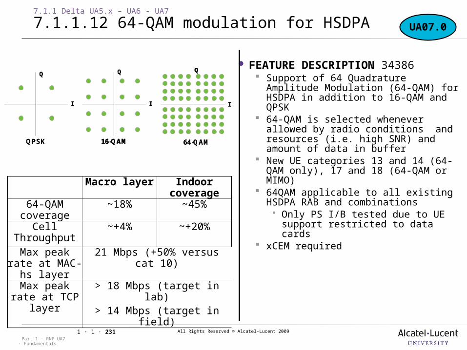
All Rights Reserved © Alcatel-Lucent 2009
· FundamentalsPart 1 · RNP UA7
1 · 1 · 231
FEATURE DESCRIPTION 34386 Support of 64 Quadrature Amplitude
Modulation (64-QAM) for HSDPA in addition to 16-QAM and QPSK
64-QAM is selected whenever allowed by radio conditions and resources (i.e. high SNR) and amount of data in buffer
New UE categories 13 and 14 (64-QAM only), 17 and 18 (64-QAM or MIMO)
64QAM applicable to all existing HSDPA RAB and combinations Only PS I/B tested due to UE
support restricted to data cards xCEM required
16-QAM
I I
Q
64-QAMQPSK
I
Q Q
16-QAM
I
16-QAM
I I
Q
I
Q
64-QAMQPSK
I
Q Q
UA07.0
Macro layer Indoor coverage
64-QAM coverage
~18% ~45%
Cell Throughput
~+4% ~+20%
Max peak rate at MAC-hs
layer
21 Mbps (+50% versus cat 10)
Max peak rate at TCP layer
> 18 Mbps (target in lab)> 14 Mbps (target in field)
7.1.1 Delta UA5.x – UA6 - UA7
7.1.1.12 64-QAM modulation for HSDPA
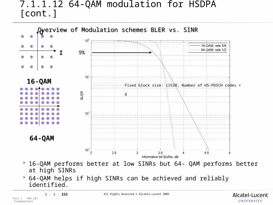
All Rights Reserved © Alcatel-Lucent 2009
· FundamentalsPart 1 · RNP UA7
1 · 1 · 232
I
Q
Fixed block size: 11520, Number of HS-PDSCH codes = 8
16-QAM performs better at low SINRs but 64- QAM performs better at high SINRs
64-QAM helps if high SINRs can be achieved and reliably identified.
•9%
16-QAM
64-QAM
Overview of Modulation schemes BLER vs. SINROverview of Modulation schemes BLER vs. SINR
7.1.1 Delta UA5.x – UA6 - UA7
7.1.1.12 64-QAM modulation for HSDPA [cont.]
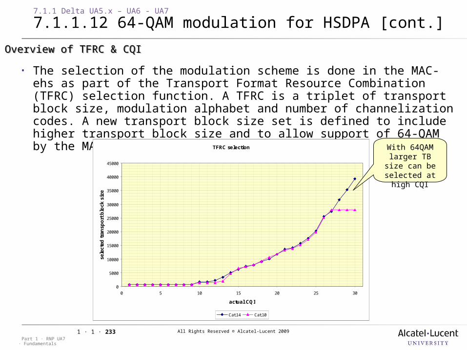
All Rights Reserved © Alcatel-Lucent 2009
· FundamentalsPart 1 · RNP UA7
1 · 1 · 233
7.1.1 Delta UA5.x – UA6 - UA7
7.1.1.12 64-QAM modulation for HSDPA [cont.]
• The selection of the modulation scheme is done in the MAC-ehs as part of the Transport Format Resource Combination (TFRC) selection function. A TFRC is a triplet of transport block size, modulation alphabet and number of channelization codes. A new transport block size set is defined to include higher transport block size and to allow support of 64-QAM by the MAC layer.
TFRC selection
0
5000
10000
15000
20000
25000
30000
35000
40000
45000
0 5 10 15 20 25 30
actual CQI
sele
cted
tra
nsp
ort
blo
ck s
ize
Cat.14 Cat.10
With 64QAM larger TB size
can be selected at high CQI
Overview of TFRC & CQI Overview of TFRC & CQI
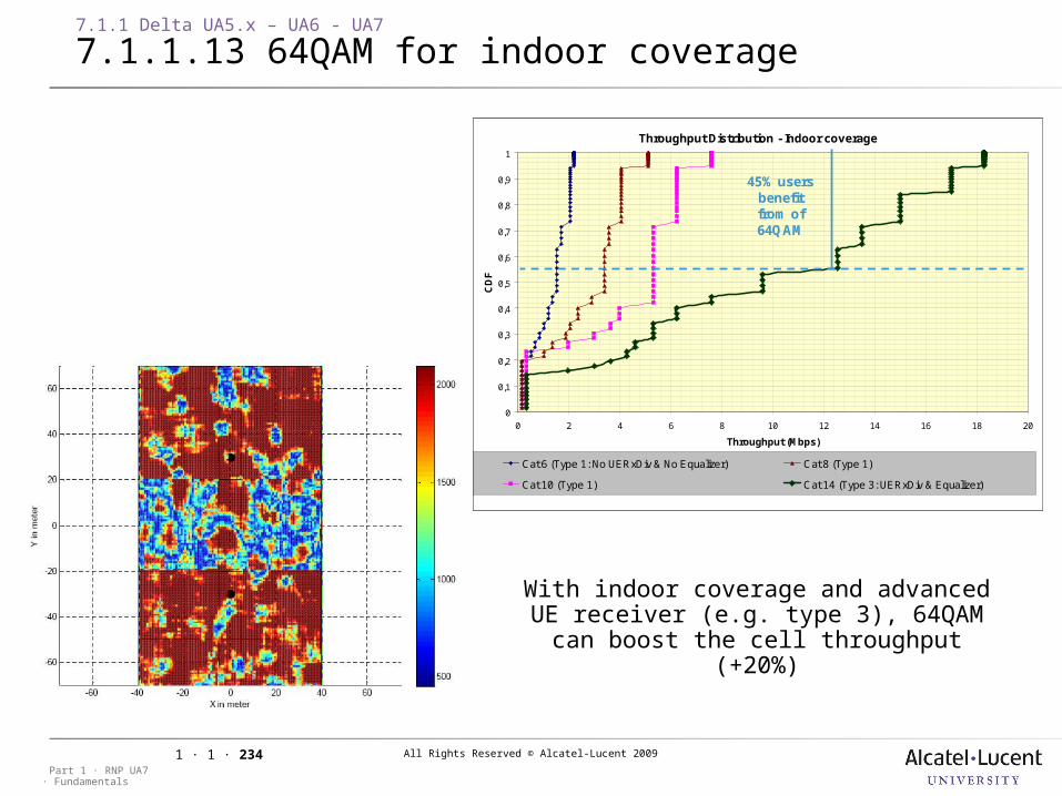
All Rights Reserved © Alcatel-Lucent 2009
· FundamentalsPart 1 · RNP UA7
1 · 1 · 234
7.1.1 Delta UA5.x – UA6 - UA7
7.1.1.13 64QAM for indoor coverage
Throughput Distribution - Indoor coverage
0
0,1
0,2
0,3
0,4
0,5
0,6
0,7
0,8
0,9
1
0 2 4 6 8 10 12 14 16 18 20
Throughput (Mbps)
CD
F
Cat 6 (Type 1: No UERxDiv & No Equalizer) Cat 8 (Type 1)
Cat 10 (Type 1) Cat 14 (Type 3: UERxDiv & Equalizer)
45% users benefit from of 64QAM
Throughput Distribution - Indoor coverage
0
0,1
0,2
0,3
0,4
0,5
0,6
0,7
0,8
0,9
1
0 2 4 6 8 10 12 14 16 18 20
Throughput (Mbps)
CD
F
Cat 6 (Type 1: No UERxDiv & No Equalizer) Cat 8 (Type 1)
Cat 10 (Type 1) Cat 14 (Type 3: UERxDiv & Equalizer)
45% users benefit from of 64QAM
With indoor coverage and advanced UE receiver (e.g. type 3), 64QAM can boost the cell throughput (+20%)
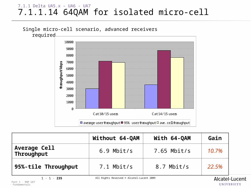
All Rights Reserved © Alcatel-Lucent 2009
· FundamentalsPart 1 · RNP UA7
1 · 1 · 235
7.1.1 Delta UA5.x – UA6 - UA7
7.1.1.14 64QAM for isolated micro-cell
Single micro-cell scenario, advanced receivers required
Without 64-QAM With 64-QAM Gain
Average Cell Throughput 6.9 Mbit/s 7.65 Mbit/s 10.7%
95%-tile Throughput 7.1 Mbit/s 8.7 Mbit/s 22.5%
0
1000
2000
3000
4000
5000
6000
7000
8000
9000
10000
Cat 10/ 15 users Cat 14/ 15 users
thro
ug
hp
ut/
kb
ps
average user throughput 95% user throughput ave. cell throughput
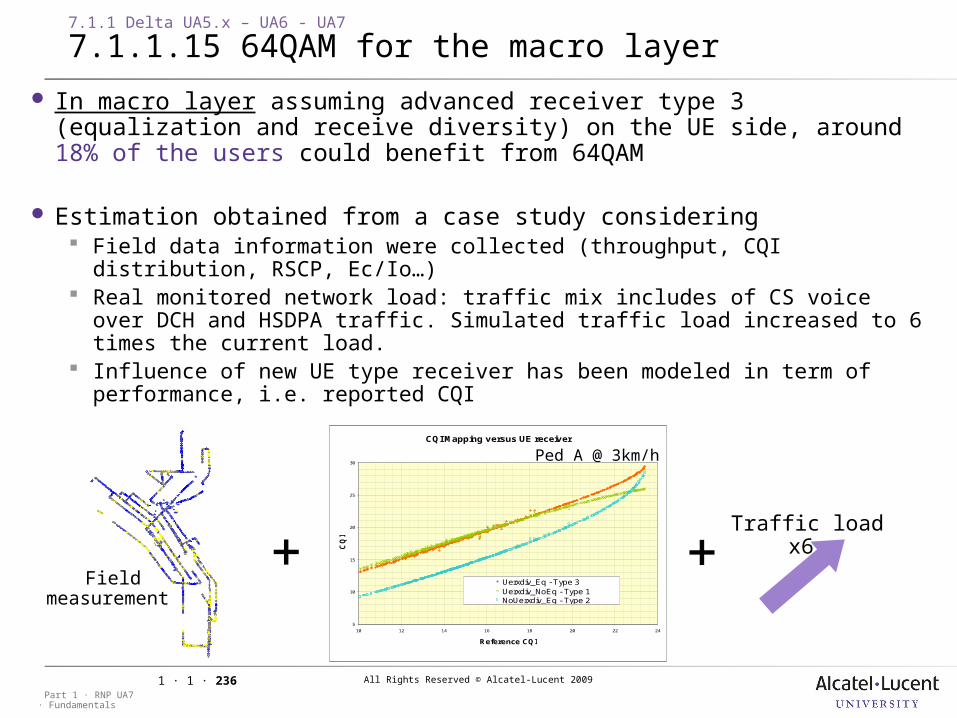
All Rights Reserved © Alcatel-Lucent 2009
· FundamentalsPart 1 · RNP UA7
1 · 1 · 236
7.1.1 Delta UA5.x – UA6 - UA7
7.1.1.15 64QAM for the macro layer
In macro layer assuming advanced receiver type 3 (equalization and receive diversity) on the UE side, around 18% of the users could benefit from 64QAM
Estimation obtained from a case study considering Field data information were collected (throughput, CQI distribution, RSCP,
Ec/Io…) Real monitored network load: traffic mix includes of CS voice over DCH and
HSDPA traffic. Simulated traffic load increased to 6 times the current load. Influence of new UE type receiver has been modeled in term of performance,
i.e. reported CQI
•Field measuremen
t
CQI Mapping versus UE receiver
5
10
15
20
25
30
10 12 14 16 18 20 22 24
Reference CQI
CQ
I
Uerxdiv_Eq - Type 3Uerxdiv_NoEq - Type 1NoUerxdiv_Eq - Type 2
•Ped A @ 3km/h
•Traffic load x6
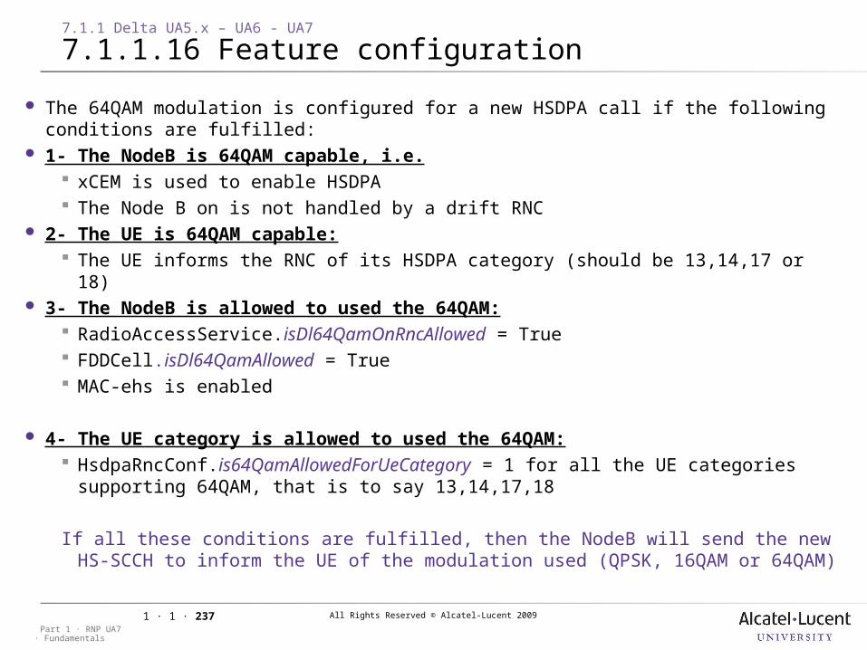
All Rights Reserved © Alcatel-Lucent 2009
· FundamentalsPart 1 · RNP UA7
1 · 1 · 237
The 64QAM modulation is configured for a new HSDPA call if the following conditions are fulfilled:
1- The NodeB is 64QAM capable, i.e. xCEM is used to enable HSDPA The Node B on is not handled by a drift RNC
2- The UE is 64QAM capable: The UE informs the RNC of its HSDPA category (should be 13,14,17 or 18)
3- The NodeB is allowed to used the 64QAM: RadioAccessService.isDl64QamOnRncAllowed = True FDDCell.isDl64QamAllowed = True MAC-ehs is enabled
4- The UE category is allowed to used the 64QAM: HsdpaRncConf.is64QamAllowedForUeCategory = 1 for all the UE categories
supporting 64QAM, that is to say 13,14,17,18
If all these conditions are fulfilled, then the NodeB will send the new HS-SCCH to inform the UE of the modulation used (QPSK, 16QAM or 64QAM)
7.1.1 Delta UA5.x – UA6 - UA7
7.1.1.16 Feature configuration
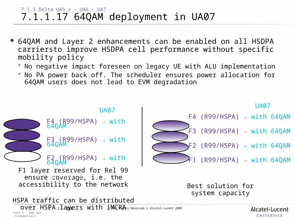
All Rights Reserved © Alcatel-Lucent 2009
· FundamentalsPart 1 · RNP UA7
1 · 1 · 238
64QAM and Layer 2 enhancements can be enabled on all HSDPA carriersto improve HSDPA cell performance without specific mobility policy No negative impact foreseen on legacy UE with ALU implementation No PA power back off. The scheduler ensures power allocation for 64QAM
users does not lead to EVM degradation
F1 layer reserved for Rel 99 ensure coverage, i.e. the accessibility to the
network
HSPA traffic can be distributed over HSPA layers with iMCRA
Best solution for system capacity
F4 (R99/HSPA) → with 64QAM
F3 (R99/HSPA) → with 64QAM
F2 (R99/HSPA) → with 64QAM
F1 (Rel 99)
F4 (R99/HSPA) → with 64QAM
F3 (R99/HSPA) → with 64QAM
F2 (R99/HSPA) → with 64QAM
F1 (R99/HSPA) → with 64QAM
UA07UA07
7.1.1 Delta UA5.x – UA6 - UA7
7.1.1.17 64QAM deployment in UA07
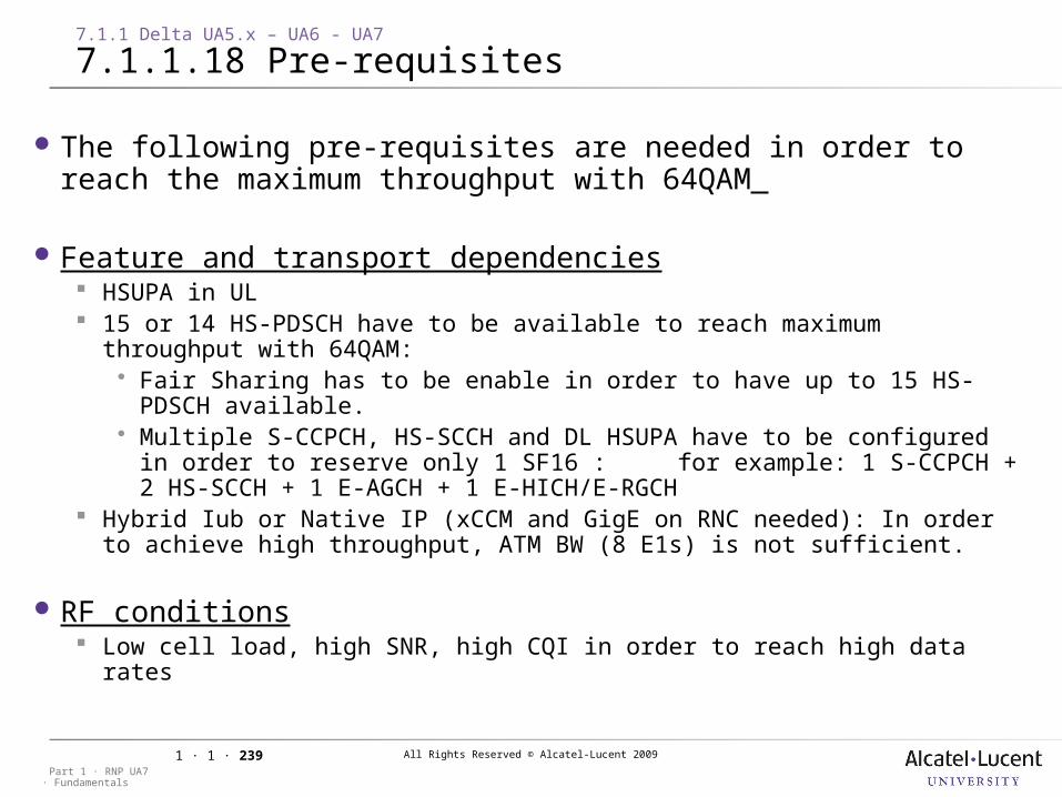
All Rights Reserved © Alcatel-Lucent 2009
· FundamentalsPart 1 · RNP UA7
1 · 1 · 239
The following pre-requisites are needed in order to reach the maximum throughput with 64QAM
Feature and transport dependencies HSUPA in UL 15 or 14 HS-PDSCH have to be available to reach maximum throughput with
64QAM: Fair Sharing has to be enable in order to have up to 15 HS-PDSCH
available. Multiple S-CCPCH, HS-SCCH and DL HSUPA have to be configured in order
to reserve only 1 SF16 : for example: 1 S-CCPCH + 2 HS-SCCH + 1 E-AGCH + 1 E-HICH/E-RGCH
Hybrid Iub or Native IP (xCCM and GigE on RNC needed): In order to achieve high throughput, ATM BW (8 E1s) is not sufficient.
RF conditions Low cell load, high SNR, high CQI in order to reach high data rates
7.1.1 Delta UA5.x – UA6 - UA7
7.1.1.18 Pre-requisites
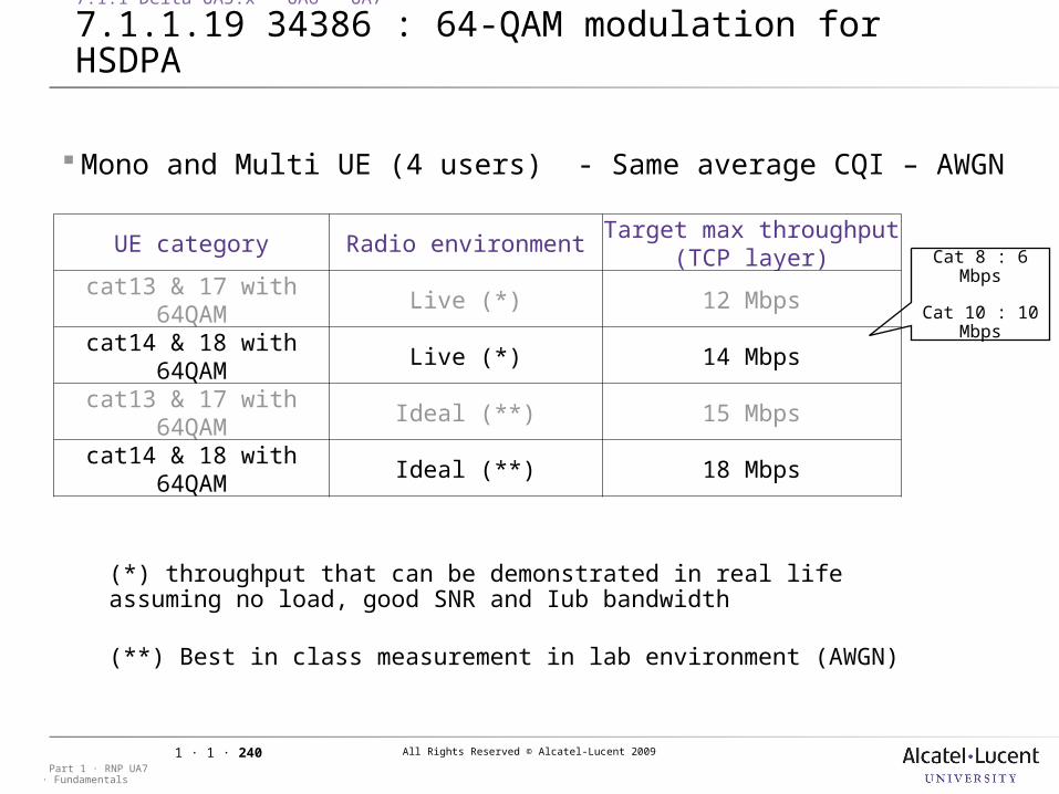
All Rights Reserved © Alcatel-Lucent 2009
· FundamentalsPart 1 · RNP UA7
1 · 1 · 240
Mono and Multi UE (4 users) - Same average CQI – AWGN
UE category Radio environmentTarget max throughput
(TCP layer)cat13 & 17 with
64QAMLive (*) 12 Mbps
cat14 & 18 with 64QAM
Live (*) 14 Mbps
cat13 & 17 with 64QAM
Ideal (**) 15 Mbps
cat14 & 18 with 64QAM
Ideal (**) 18 Mbps
(*) throughput that can be demonstrated in real life assuming no load, good SNR and Iub bandwidth
(**) Best in class measurement in lab environment (AWGN)
Cat 8 : 6 Mbps
Cat 10 : 10 Mbps
7.1.1 Delta UA5.x – UA6 - UA7
7.1.1.19 34386 : 64-QAM modulation for HSDPA
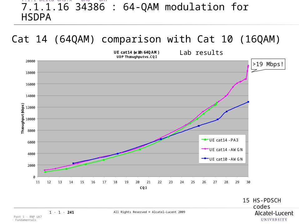
All Rights Reserved © Alcatel-Lucent 2009
· FundamentalsPart 1 · RNP UA7
1 · 1 · 241
Cat 14 (64QAM) comparison with Cat 10 (16QAM)UE cat 14 (with 64QAM)
UDP Throughput vs. CQI
0
2000
4000
6000
8000
10000
12000
14000
16000
18000
20000
11 12 13 14 15 16 17 18 19 20 21 22 23 24 25 26 27 28 29 30
CQI
Th
rou
gh
pu
t (k
bp
s)
UE cat 14 - PA3
UE cat 14 - AWGN
UE cat 10 - AWGN
Lab results
>19 Mbps!
15 HS-PDSCH codes
7.1.1 Delta UA5.x – UA6 - UA7
7.1.1.16 34386 : 64-QAM modulation for HSDPA
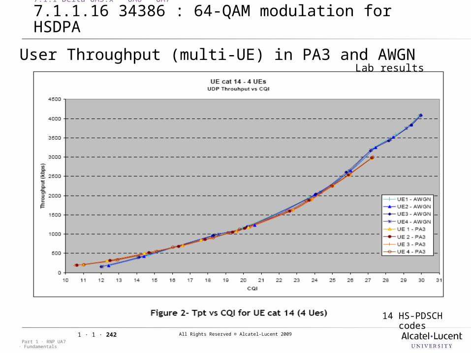
All Rights Reserved © Alcatel-Lucent 2009
· FundamentalsPart 1 · RNP UA7
1 · 1 · 242
User Throughput (multi-UE) in PA3 and AWGNLab results
14 HS-PDSCH codes
7.1.1 Delta UA5.x – UA6 - UA7
7.1.1.16 34386 : 64-QAM modulation for HSDPA
All Rights Reserved © Alcatel-Lucent 2009
· FundamentalsPart 1 · RNP UA7
1 · 1 · 243
64QAM can provide significant user throughput boost for pico/micro and indoor coverage
It is expected that 64QAM could be used around 18% of the cell area in the macro layer delivering a small cell throughput gain Especially if weighted with UE support availability
64QAM requires enhanced UE receiver which largely benefits to user and cell throughput even beyond 64QAM coverage area
It is expected that 64QAM activation on HSDPA capable cells has no negative impact on legacy UE, system performance and cell capacity
7.1.1 Delta UA5.x – UA6 - UA7
7.1.1.16 34386 : 64-QAM modulation for HSDPA

All Rights Reserved © Alcatel-Lucent 2009
· FundamentalsPart 1 · RNP UA7
1 · 1 · 244
7 Deltas and Modifications
All Rights Reserved © Alcatel-Lucent 2009
· FundamentalsPart 1 · RNP UA7
1 · 1 · 245
End of ModuleEnd of Course