Embed Size (px)
Citation preview
UN CONTROVENTO SPECIALE AD INSTABILITÀ IMPEDITA PER IL MIGLIORAMENTO SISMICO DI EDIFICI IN C.A.:
PROGETTO E SPERIMENTAZIONE
A SPECIAL TYPE OF BUCKLING-RESTRAINED BRACE FOR SEISMIC RETROFITTING OF RC BUILDINGS:
DESIGN AND TESTING
Mario D’Aniello, Gaetano Della Corte, Federico M. Mazzolani University of Naples “Federico II”, Department of Structural Engineering Naples, Italy
[email protected]; [email protected]; [email protected]
ABSTRACT Full-scale cyclic inelastic tests on a real RC building strengthened by means of a special type of Buckling-Restrained Brace (BRB) are presented and discussed. The tested BRB is a special detachable “only-steel” device, consisting of a rectangular steel plate encased in a bolted re-straining steel sleeve. The main advantage of the system consists in the possibility to hide it within the space between the facing and the backing of common masonry infill walls. The pa-per describes failure modes and inelastic response of the bracing system.
SOMMARIO In questa memoria viene presentata e discussa una prova sperimentale condotta su un edificio reale, in c.a., rinforzato con un tipo speciale di controvento ad instabilità impedita (BRB) e sottoposto a forze orizzontali di piano, cicliche, in campo inelastico. Il BRB provato è un di-spositivo smontabile, interamente di acciaio, giacché costituito da un piatto rettangolare inse-rito all’interno di un manicotto di acciaio bullonato. Il principale vantaggio del sistema consi-ste nella possibilità di essere mascherato agevolmente nella camera d’aria tra le due fodere delle usuali tamponature in laterizio. Il lavoro descrive le modalità di collasso e la risposta i-nelastica del sistema di controvento.
1 INTRODUCTION Buckling Restrained Braces (BRBs) can be considered as one of the most efficient structural system for resisting lateral forces due to earthquakes, because they provide complete truss ac-tion with the same response both in tension and compression, characterized by compact and round hysteresis loops [1, 2]. The concept of BRBs is simple: a slender core plate transmits axial forces, and a restraining sleeve prevents buckling of the core plate. This arrangement lets the brace to exhibit the same behavior both in tension and compression. A number of approaches have been suggested,
178 M. D’Aniello, G. Della Corte, F.M. Mazzolani
such as enclosing a ductile steel core (rectangular or cruciform plates, circular rods, etc.) ei-ther in a continuous concrete filled tube or within a continuous steel tube. In the first case, the brace is called “unbonded” BRB, because the surface of the core is treated with unbonding materials to allow the relative displacement with the sleeve to be developed. In the second case, the steel core is separated by the sleeve with a small gap and it is usually called “only-steel” BRB. In both cases, the assembly is detailed so that the yielding core can deform longi-tudinally independent from the mechanism that restrains lateral and local buckling. “Only-steel” BRBs have some advantages over “unbonded” braces. In fact, this type of BRBs can be designed to be detachable. Hence, they could be inspected after each seismic event and, if necessary, the yielded steel core could be replaced by a new one. Moreover, a detach-able BRB allows maintenance during the life-time. To do this, the restraining tubes are con-nected by bolted steel connections [3,4]. Moreover, an “only-steel” BRB is lighter than an ‘unbonded’ one; this implies a technical and economical advantage during the assembling. These considerations led to study a special “only-steel” detachable BRB, to be used for im-proving the seismic response of existing buildings. To reach this objective full-scale tests on real RC structures equipped with BRBs have been carried out. This paper shows the results of the last test, concerning a new typology of “only-steel” BRB.
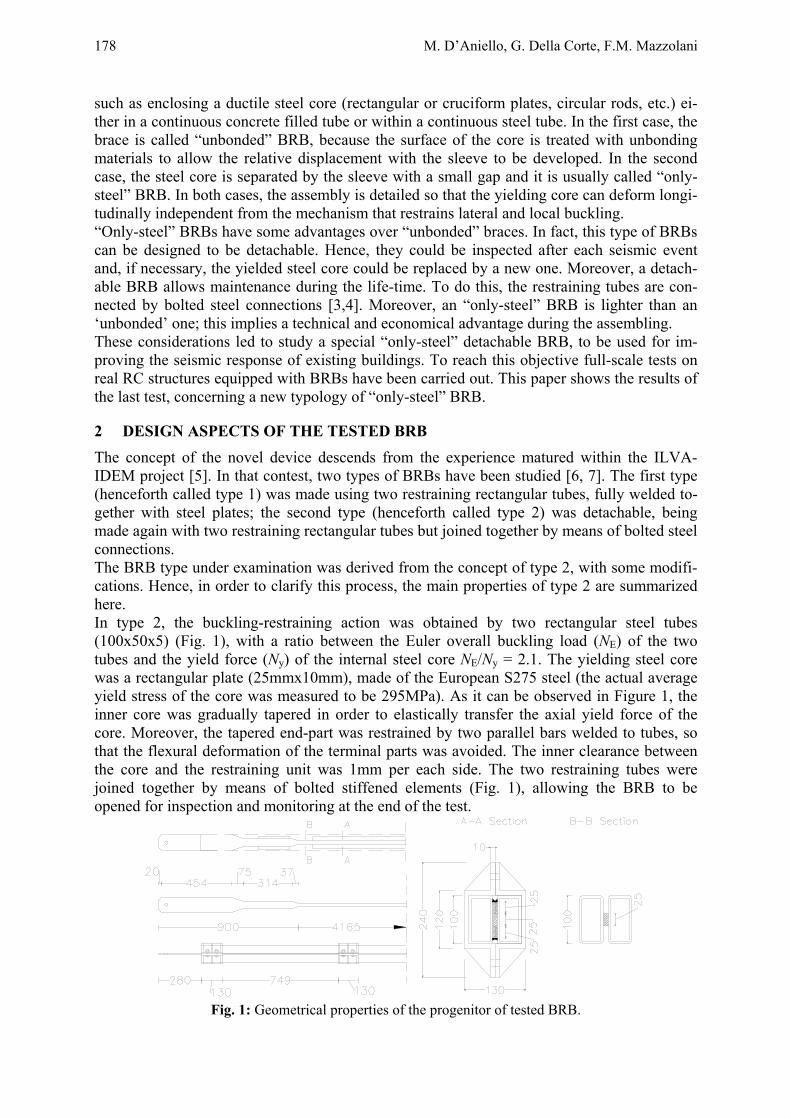
2 DESIGN ASPECTS OF THE TESTED BRB The concept of the novel device descends from the experience matured within the ILVA-IDEM project [5]. In that contest, two types of BRBs have been studied [6, 7]. The first type (henceforth called type 1) was made using two restraining rectangular tubes, fully welded to-gether with steel plates; the second type (henceforth called type 2) was detachable, being made again with two restraining rectangular tubes but joined together by means of bolted steel connections. The BRB type under examination was derived from the concept of type 2, with some modifi-cations. Hence, in order to clarify this process, the main properties of type 2 are summarized here. In type 2, the buckling-restraining action was obtained by two rectangular steel tubes (100x50x5) (Fig. 1), with a ratio between the Euler overall buckling load (NE) of the two tubes and the yield force (Ny) of the internal steel core NE/Ny = 2.1. The yielding steel core was a rectangular plate (25mmx10mm), made of the European S275 steel (the actual average yield stress of the core was measured to be 295MPa). As it can be observed in Figure 1, the inner core was gradually tapered in order to elastically transfer the axial yield force of the core. Moreover, the tapered end-part was restrained by two parallel bars welded to tubes, so that the flexural deformation of the terminal parts was avoided. The inner clearance between the core and the restraining unit was 1mm per each side. The two restraining tubes were joined together by means of bolted stiffened elements (Fig. 1), allowing the BRB to be opened for inspection and monitoring at the end of the test.
Fig. 1: Geometrical properties of the progenitor of tested BRB.
Un controvento speciale ad instabilità impedita per il miglioramento sismico di edifici in c.a. 179
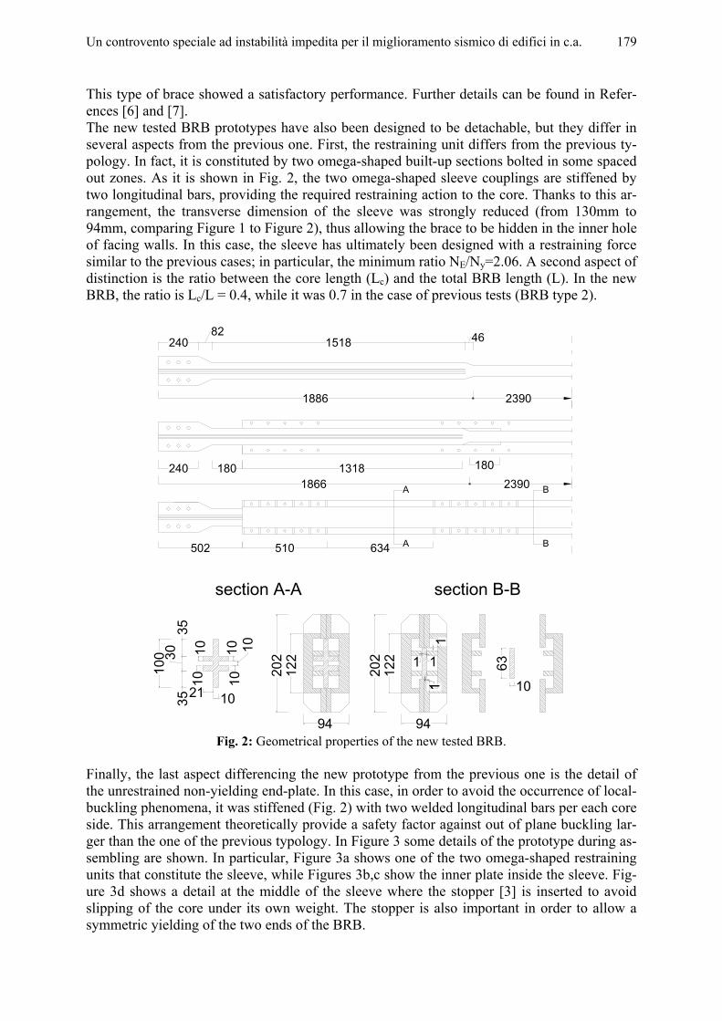
This type of brace showed a satisfactory performance. Further details can be found in Refer-ences [6] and [7]. The new tested BRB prototypes have also been designed to be detachable, but they differ in several aspects from the previous one. First, the restraining unit differs from the previous ty-pology. In fact, it is constituted by two omega-shaped built-up sections bolted in some spaced out zones. As it is shown in Fig. 2, the two omega-shaped sleeve couplings are stiffened by two longitudinal bars, providing the required restraining action to the core. Thanks to this ar-rangement, the transverse dimension of the sleeve was strongly reduced (from 130mm to 94mm, comparing Figure 1 to Figure 2), thus allowing the brace to be hidden in the inner hole of facing walls. In this case, the sleeve has ultimately been designed with a restraining force similar to the previous cases; in particular, the minimum ratio NE/Ny=2.06. A second aspect of distinction is the ratio between the core length (Lc) and the total BRB length (L). In the new BRB, the ratio is Lc/L = 0.4, while it was 0.7 in the case of previous tests (BRB type 2).
180 180
510 634502
240 13181866 2390
1886 2390
46240 151882
A
A
B
B
122
94
202
section A-A section B-B
63
10
100
3530
35
21
1010
10
101010
122
94
202
11
11
1
Fig. 2: Geometrical properties of the new tested BRB.
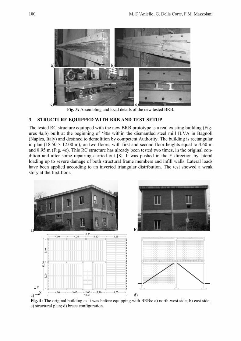
Finally, the last aspect differencing the new prototype from the previous one is the detail of the unrestrained non-yielding end-plate. In this case, in order to avoid the occurrence of local-buckling phenomena, it was stiffened (Fig. 2) with two welded longitudinal bars per each core side. This arrangement theoretically provide a safety factor against out of plane buckling lar-ger than the one of the previous typology. In Figure 3 some details of the prototype during as-sembling are shown. In particular, Figure 3a shows one of the two omega-shaped restraining units that constitute the sleeve, while Figures 3b,c show the inner plate inside the sleeve. Fig-ure 3d shows a detail at the middle of the sleeve where the stopper [3] is inserted to avoid slipping of the core under its own weight. The stopper is also important in order to allow a symmetric yielding of the two ends of the BRB.
180 M. D’Aniello, G. Della Corte, F.M. Mazzolani
a) b)
c) d) Fig. 3: Assembling and local details of the new tested BRB.
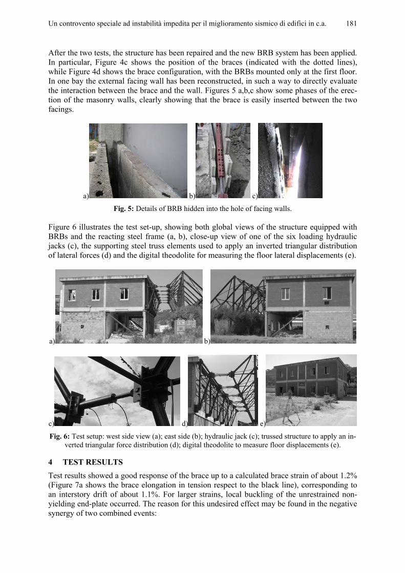
3 STRUCTURE EQUIPPED WITH BRB AND TEST SETUP The tested RC structure equipped with the new BRB prototype is a real existing building (Fig-ures 4a,b) built at the beginning of ‘80s within the dismantled steel mill ILVA in Bagnoli (Naples, Italy) and destined to demolition by competent Authority. The building is rectangular in plan (18.50 × 12.00 m), on two floors, with first and second floor heights equal to 4.60 m and 8.95 m (Fig. 4c). This RC structure has already been tested two times, in the original con-dition and after some repairing carried out [8]. It was pushed in the Y-direction by lateral loading up to severe damage of both structural frame members and infill walls. Lateral loads have been applied according to an inverted triangular distribution. The test showed a weak story at the first floor.
a)
b)
c)
Y X
18,504,00 4,25 4,20 4,55
18,504,00 3,45 2,00 2,70 4,55
12,0
05,
106,
00
d) Fig. 4: The original building as it was before equipping with BRBs: a) north-west side; b) east side; c) structural plan; d) brace configuration.
Un controvento speciale ad instabilità impedita per il miglioramento sismico di edifici in c.a. 181
After the two tests, the structure has been repaired and the new BRB system has been applied. In particular, Figure 4c shows the position of the braces (indicated with the dotted lines), while Figure 4d shows the brace configuration, with the BRBs mounted only at the first floor. In one bay the external facing wall has been reconstructed, in such a way to directly evaluate the interaction between the brace and the wall. Figures 5 a,b,c show some phases of the erec-tion of the masonry walls, clearly showing that the brace is easily inserted between the two facings.
a) b) c)
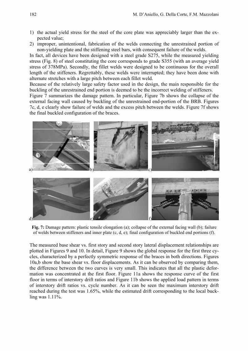
Fig. 5: Details of BRB hidden into the hole of facing walls. Figure 6 illustrates the test set-up, showing both global views of the structure equipped with BRBs and the reacting steel frame (a, b), close-up view of one of the six loading hydraulic jacks (c), the supporting steel truss elements used to apply an inverted triangular distribution of lateral forces (d) and the digital theodolite for measuring the floor lateral displacements (e).
a) b)
c) d) e)
Fig. 6: Test setup: west side view (a); east side (b); hydraulic jack (c); trussed structure to apply an in-verted triangular force distribution (d); digital theodolite to measure floor displacements (e).
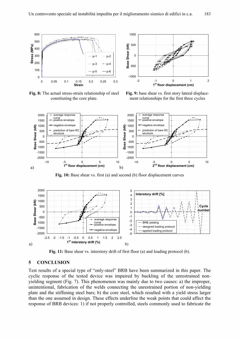
4 TEST RESULTS Test results showed a good response of the brace up to a calculated brace strain of about 1.2% (Figure 7a shows the brace elongation in tension respect to the black line), corresponding to an interstory drift of about 1.1%. For larger strains, local buckling of the unrestrained non-yielding end-plate occurred. The reason for this undesired effect may be found in the negative synergy of two combined events:
182 M. D’Aniello, G. Della Corte, F.M. Mazzolani
1) the actual yield stress for the steel of the core plate was appreciably larger than the ex-pected value;
2) improper, unintentional, fabrication of the welds connecting the unrestrained portion of non-yielding plate and the stiffening steel bars, with consequent failure of the welds.
In fact, all devices have been designed with a steel grade S275, while the measured yielding stress (Fig. 8) of steel constituting the core corresponds to grade S355 (with an average yield stress of 378MPa). Secondly, the fillet welds were designed to be continuous for the overall length of the stiffeners. Regrettably, these welds were interrupted; they have been done with alternate stretches with a large pitch between each fillet weld. Because of the relatively large safety factor used in the design, the main responsible for the buckling of the unrestrained end portion is deemed to be the incorrect welding of stiffeners. Figure 7 summarizes the damage pattern. In particular, Figure 7b shows the collapse of the external facing wall caused by buckling of the unrestrained end-portion of the BRB. Figures 7c, d, e clearly show failure of welds and the excess pitch between the welds. Figure 7f shows the final buckled configuration of the braces.
a) b) c)
d) e) f)
Fig. 7: Damage pattern: plastic tensile elongation (a); collapse of the external facing wall (b); failure of welds between stiffeners and inner plate (c, d, e); final configuration of buckled end portions (f).
The measured base shear vs. first story and second story lateral displacement relationships are plotted in Figures 9 and 10. In detail, Figure 9 shows the global response for the first three cy-cles, characterized by a perfectly symmetric response of the braces in both directions. Figures 10a,b show the base shear vs. floor displacements. As it can be observed by comparing them, the difference between the two curves is very small. This indicates that all the plastic defor-mation was concentrated at the first floor. Figure 11a shows the response curve of the first floor in terms of interstory drift ratios and Figure 11b shows the applied load pattern in terms of interstory drift ratios vs. cycle number. As it can be seen the maximum interstory drift reached during the test was 1.65%, while the estimated drift corresponding to the local buck-ling was 1.11%.
Un controvento speciale ad instabilità impedita per il miglioramento sismico di edifici in c.a. 183
0
100
200
300
400
500
600
0 0.05 0.1 0.15 0.2 0.25 0.3Strain
Stre
ss (M
Pa)
p-1 p-2
p-3 p-4
p-5 p-6
-1000
-500
0
500
1000
-2 -1 0 1 21st floor displacement (cm)
Bas
e Sh
ear (
kN)
Fig. 8: The actual stress-strain relationship of steel
constituting the core plate. Fig. 9: base shear vs. first story lateral displace-
ment relationships for the first three cycles
a)
-2000
-1500
-1000
-500
0
500
1000
1500
2000
-10 -5 0 5 101st floor displacement (cm)
Bas
e Sh
ear (
kN)
average responsecurvepositive envelope
negative envelope
prediction of bare RCstructureSerie8
b)
-2000
-1500
-1000
-500
0
500
1000
1500
2000
-10 -5 0 5 102nd floor displacement (cm)
Bas
e Sh
ear (
kN)
average responsecurvepositive envelope
negative envelope
prediction of bare RCstructureSerie8
Fig. 10: Base shear vs. first (a) and second (b) floor displacement curves
a)
-2000
-1500
-1000
-500
0
500
1000
1500
2000
-2.5 -2 -1.5 -1 -0.5 0 0.5 1 1.5 2 2.51st interstory drift (%)
Bas
e Sh
ear (
kN)
average responsecurvepositive envelope
negative envelope
b)
-5-4-3-2-1012345
Interstory drift [%]
Cycle number
BRB yieldingdesigned loading protocolapplied loading protocol
Fig. 11: Base shear vs. interstory drift of first floor (a) and loading protocol (b).
5 CONCLUSION Test results of a special type of “only-steel” BRB have been summarized in this paper. The cyclic response of the tested device was impaired by buckling of the unrestrained non-yielding segment (Fig. 7). This phenomenon was mainly due to two causes: a) the improper, unintentional, fabrication of the welds connecting the unrestrained portion of non-yielding plate and the stiffening steel bars; b) the core steel, which resulted with a yield stress larger than the one assumed in design. These effects underline the weak points that could affect the response of BRB devices: 1) if not properly controlled, steels commonly used to fabricate the
184 M. D’Aniello, G. Della Corte, F.M. Mazzolani
restrained yielding segment may have a wide range of yield strength; 2) the difficulty to pro-vide a reliable quality control in the manufacturing process, that is characterized by erection tolerances generally lower than those of conventional braced frames, combined with more complex local details.
ACKNOWLEDGMENT The following subjects are gratefully acknowledged for having provided the financial support: 1. the RELUIS Project– Task 5 “Development of innovative approaches to design steel
and composite steel-concrete structures” 2. PRIN 2005-2007 project “Advanced steel braces with decoupled design parameters”.
The financial support is gratefully acknowledged. 3. PROHITEC project (Earthquake Protection of Historical Buildings by Reversible
Mixed Technologies.
REFERENCES [1] Wada A., Nakashima M. From infancy to maturity of buckling restrained braces re-
search. Proceedings of the 13th World Conference on Earthquake Engineering, Vancou-ver (Canada) 2004.
[2] Black C., Makris N., Aiken I. Component testing, stability analysis and characterization of buckling restrained braces. PEER Report 2002/08, Pacific Earthquake Engineering Research Center, University of California at Berkeley, 2002.
[3] Tsai, K.C., Lai, J.W., Hwang, Y.C., Lin, S.L. & Weng, Y.T. Research and application of double-core buckling restrained braces in Taiwan. Proceedings of the 13th World Conference on Earthquake Engineering, Vancouver (Canada) 2004a.
[4] Tsai, K.C., Weng, Y.T., Lin, S.L. & Goel, S. Pseudo-dynamic test of a full-scale CFT/BRB frame: Part1-Performance Based Design. Proceedings of the 13th World Con-ference on Earthquake Engineering, Vancouver (Canada) 2004b.
[5] Mazzolani, F.M. (Co-ord. and Ed.). “Seismic upgrading of RC buildings by advanced techniques. The ILVA-IDEM research project”. POLIMETRICA Publisher, 2006.
[6] Della Corte G., D’Aniello M., Mazzolani F.M. “Seismic Upgradi ng of RC buildings using Buckling Restrained Braces: full-scale experimental tests”. Proceedings of the XX C.T.A. Conference–First int. Workshop on Advances in Steel Constructions, Ischia (It-aly), 26-28 September, 2005.
[7] D’Aniello, M., Della Corte, G. & Mazzolani, F.M. Seismic Upgrading of RC Buildings by Steel Eccentric Braces: Experimental Results vs Numerical Modeling. Proceedings of the STESSA Conference, Yokohama (Japan) 14-17 August, 2006.
[8] Della Corte G., Mazzolani F.M. Full-scale lateral-loading tests of a real masonry-infilled RC building. Proceedings of the Second fib Congress, Naples (Italy) 5-8 June 2006.
KEYWORDS Buckling-Restrained Brace; seismic upgrading; full-scale test; buckling; cyclic response.