Embed Size (px)
Citation preview
Universal Integration of the Internet of Things through an IPv6-
based Service Oriented Architecture enabling heterogeneous components interoperability
Grant agreement for: Collaborative project Grant agreement no.: 288445 Start date of project: October 1st, 2011 (36 months duration)
Deliverable D6.6 Multi-Systems Integration for Smart Building Environment Report
Contract Due Date 31/05/2014
Submission Date 26/05/2014
Version 1.0
Responsible Partner University for Applied Sciences Western Switzerland (HES-SO)
Author List Alex C. Olivieri, François Morard, Gianluca Rizzo, Yann Bocchi.
Dissemination level CO
Keywords Internet of Things, IPv6
Project Coordinator: Mandat International (MI) Sébastien Ziegler [email protected]
IoT6 D6.6 Multi-System Integration for Smart Building Environment Report
2
Table of Contents
1 Introduction ............................................................................................................... 4
1.1 Overview of IoT6 European Project ........................................................................... 4
1.2 Overview of Work Package 6 (WP6) ........................................................................... 4
1.3 Overview of the Deliverable ....................................................................................... 5
2 Problem and Requirements Analysis .......................................................................... 6
2.1 Problem Description ................................................................................................... 6
2.2 Requirements Analysis ............................................................................................... 6
2.2.1 Primary Use Cases ................................................................................................ 7
2.2.2 Glossary ................................................................................................................ 7
2.2.3 Scenarios .............................................................................................................. 8
2.2.4 Domain Model .................................................................................................... 10
3 Technologies used for the Project ............................................................................. 11
3.1 Distributed Middleware ........................................................................................... 11
3.1.1 Publish/Subscribe ............................................................................................... 11
3.1.1.1 Orion Context Broker .................................................................................... 12
3.2 IoT6 Ecosystem ......................................................................................................... 13
3.2.1 IoT6 Stack ........................................................................................................... 13
3.2.2 IoTSyS ................................................................................................................. 13
3.2.3 Universal Device Gateway (UDG) ....................................................................... 14
3.3 Smart Building Applications ..................................................................................... 14
3.3.1 Microsoft Kinect for Windows ............................................................................ 15
3.3.2 Philips Hue (Personal Wireless Lighting) ............................................................ 15
3.3.3 XBee Temperature and Brightness Sensor ......................................................... 15
3.3.4 Android App........................................................................................................ 15
3.3.5 Google Glass ....................................................................................................... 15
3.3.6 Google SpreadSheet ........................................................................................... 16
4 Problem Analysis ..................................................................................................... 16
4.1 Structure Dimension................................................................................................. 16
4.2 Interactions Dimension ............................................................................................ 18
4.2.1 Interactions Definition ........................................................................................ 18
4.2.1.1 Entity – ConnectionManager ....................................................................... 19
4.2.1.2 Entity – MessageManager ............................................................................ 19
4.2.1.3 MessageManager – Translator ..................................................................... 20
4.3 Behavior Dimension ................................................................................................. 20
4.3.1 ConnectionManager ........................................................................................... 20
4.3.2 MessageManager ............................................................................................... 21
4.3.3 Translator ............................................................................................................ 21
4.3.4 Full Business Logic .............................................................................................. 21
5 Design ...................................................................................................................... 22
5.1 Orion Context Broker & Logical Architecture ........................................................... 22
5.1.1 Introduction to the Orion Context Broker .......................................................... 22
5.1.2 FI-WARE NGSI Specification ................................................................................ 22
5.1.2.1 FI-WARE NGSI-9 ............................................................................................ 23
5.1.2.2 FI-WARE NGSI-10 .......................................................................................... 23
5.1.3 Data Format ........................................................................................................ 24
IoT6 D6.6 Multi-System Integration for Smart Building Environment Report
3
5.1.4 Logical Architecture including the Orion Context Broker ................................... 24
5.1.5 Consequences brought by the Orion Context Broker ........................................ 25
5.2 Design of Entities ...................................................................................................... 26
5.3 Design of ConnectionManager ................................................................................. 27
5.4 Design of MessageManager ..................................................................................... 27
5.5 Design of Translator .................................................................................................. 27
5.6 Message .................................................................................................................... 28
5.7 Data .......................................................................................................................... 28
6 Scenario ................................................................................................................... 30
6.1 Scenario Description ................................................................................................ 30
6.1.1 Regular Mode Situation Management ............................................................... 31
6.1.2 Switch to Comfort Mode .................................................................................... 32
6.1.3 Comfort Mode Room Management ................................................................... 33
6.1.4 Switch to Regular Mode ..................................................................................... 33
6.1.5 Query Information through Android App ........................................................... 34
7 Implementation & Deployment Details .................................................................... 35
7.1 Components’ Classification ...................................................................................... 35
7.1.1 Publisher Entities ................................................................................................ 35
7.1.2 Query Entities ..................................................................................................... 35
7.1.3 Subscriber Entities .............................................................................................. 35
7.2 Components’ Implementation ................................................................................. 36
7.2.1 Publisher Entities ................................................................................................ 36
7.2.1.1 XBee Brightness Sensor ................................................................................ 37
7.2.1.2 Google Glass ................................................................................................. 38
7.2.1.3 Microsoft Kinect for Windows ...................................................................... 38
7.2.2 Query Entities & Android App ............................................................................ 39
7.2.3 Subscriber Entities .............................................................................................. 40
Web Client Phase .......................................................................................................... 40
Web Service Phase ....................................................................................................... 41
7.2.3.1 IoTSyS ........................................................................................................... 42
7.2.3.2 Google Spreadsheet ..................................................................................... 42
7.2.3.3 UDG .............................................................................................................. 43
7.2.3.4 Philips Lighting (HUE) ................................................................................... 43
8 Conclusion and Outlook ........................................................................................... 45
9 References ............................................................................................................... 46
10 List of Figures ........................................................................................................... 47
11 List of Tables ............................................................................................................ 47
IoT6 D6.6 Multi-System Integration for Smart Building Environment Report
4
1 Introduction
This section recalls the goals of Work Package 6 “Mobile network, STIS & business processes interactions” in the European project IoT61, focusing on Task T6.5 “Enabling multi-systems integration for smart building environment”. It also outlines the work that has been done according to the Description of Work which is the subject of this deliverable.
1.1 Overview of IoT6 European Project
IoT6 is a three-year FP7 European research project on the future Internet of Things IoT). It aims at exploiting the potential of IPv6 and related standards (6LoWPAN, COAP, etc.) to overcome current shortcomings and fragmentation of the IoT. Its main challenges and objectives are to research, design and develop a highly scalable IPv6-based Service-Oriented Architecture to achieve interoperability, mobility, cloud computing integration and intelligence distribution among heterogeneous smart things components, applications and services. The potential of the proposed architecture is researched by exploring innovative forms of interactions such as:
Information and intelligence distribution.
Multi-protocol interoperability with, and among, heterogeneous devices.
Device mobility and mobile phone networks integration, to provide ubiquitous access
and seamless communication.
Cloud computing integration with Software as a Service (SaaS).
IPv6 - Smart Things Information Services (STIS) innovative interactions.
The main outcomes of IoT6 are recommendations on how IPv6 features can be exploited for the Internet of Things and an open and well-defined IPv6-based Service Oriented Architecture enabling interoperability, mobility, cloud computing and intelligence distribution among heterogeneous smart things components, applications and services, including management tools for business processes.
1.2 Overview of Work Package 6 (WP6)
WP6 addresses challenges related to the integration of the IoT6 ecosystem with mainstream business applications and to the Service Oriented Architecture of IoT6. It takes into account recent developments, such as OASIS standardizations and cloud computing. It will make sure that the IoT6 architecture is able to serve - and bring added value to - existing building applications. WP6 is composed of five tasks that address the following areas:
a) To integrate and explore the potential interaction with business process applications
using its cloud computing platform of Software as a Service (SaaS) to interconnect our
IPv6-based architecture with virtual applications, such as management tools for
maintenance processes;
1 http://www.iot6.eu/

IoT6 D6.6 Multi-System Integration for Smart Building Environment Report
5
b) To explore the integration of our architecture into mobile networks, and exploring
solutions such as IP Multimedia Subsystem (IMS);
c) To research the interaction and integration of IPv6 with STIS environment. A particular
focus will be given to the potential interaction and/or integration of STIS and IPv6
addresses;
d) To research and explore the integration in IoT6 architecture of existing building
automation sub-systems and applications.
1.3 Overview of the Deliverable
This deliverable expounds the work done in Task T6.5, named: “Enabling multi-systems integration for smart building environment.”
This Task researches and explores the integration of the IoT6 architecture with existing building automation sub-systems and applications, such as 3-D visualization tools, lighting control systems, security monitoring tools, access control tools. This Task addresses current modeling and meta-communication standards related to this domain. The outcome will be the designing and proposing of an integration model which will be demonstrated by at least two sub-system and application integrations according to the IoT6 architecture.
While the work to accomplish this task was being performed, different issues were faced that led to the following challenges:
a) To understand which was the right integration model that could fit well with the goals of
the Task;
b) To discover how the business sub-system components could be integrated with the IoT6
architecture;
c) To identify the business sub-system components, that could be used to provide a better
impact for the IoT6 project towards the real world;
d) To engineer a design and implementation to test the activities that the Task was defined
for;
e) To plan an interesting real case scenario in order to test and validate the system, as an
outcome of Task T6.5.
This deliverable is organized as follows: Section 2 studies the problems that Task T6.5 aims to solve and analyses the requirements envisaged; Section 3 introduces the technologies applied to demonstrate the solution that the resulting system will use; Section 4 analyses in detail the problems identified based on the requirements’ analysis and shows the artifacts that describe what the components present in the system, namely their behaviors and interactions, abstracted from the technologies selected; Section 5 designs the system starting with the artifacts previously identified, and shows how the system architecture is adapted according to the technologies selected; Section 6 proposes a scenario for a smart hospital room management that will be the starting point for the deployment of the system; Section 7 explains the implementation details of the system and explains how to deploy entities to reach the integration required.
Section 8 summarizes the work performed and provides conclusions to show that the requirements have been satisfied and proposes some outlooks about the applicability of the implemented system.
IoT6 D6.6 Multi-System Integration for Smart Building Environment Report
6
Throughout the deliverable, software engineering methodologies are used to create all artifacts needed to accomplish the work.
2 Problem and Requirements Analysis
In this section, we detail the problem that Task T6.5 addresses, then the Requirements Analysis of the problem is performed and finally, all artifacts necessary to fully meet the requirements envisaged are provided.
The target of this section is to provide the foundation that will allow the designers and implementers to create the system required.
2.1 Problem Description
The main goal is to integrate the IoT6 ecosystem with existing building technologies, both systems (such as building automation systems) and applications/tools. The spectrum of those building technologies is too vast to interconnect with the IoT6 ecosystem through an IoT6 dedicated interface. Building technologies have their own interfaces and the adaptation would be too costly in terms of effort. Therefore, we use a software communication middleware that allows the interactions between the entities, whether they are IoT6 entities or building technologies entities, by providing some interfaces that could be easily adapted to all cases.
Task T6.5 does not define any specific scenario to test the resulting solution; it only sets the constraint of using two sub-systems and applications to ensure that such integration between IoT6 ecosystem and the building technologies domain can be demonstrated, as specified in the Description of Work.
2.2 Requirements Analysis
In this subsection, the focus is on the Requirements Analysis, in order to determine accurately all functional requirements that the partners had in mind when they wrote the Description of Work. The purpose is to produce all artifacts necessary to meet the partners’ requirements in order to have a full view of the system needed to be created.
IoT6 D6.6 Multi-System Integration for Smart Building Environment Report
7
2.2.1 Primary Use Cases
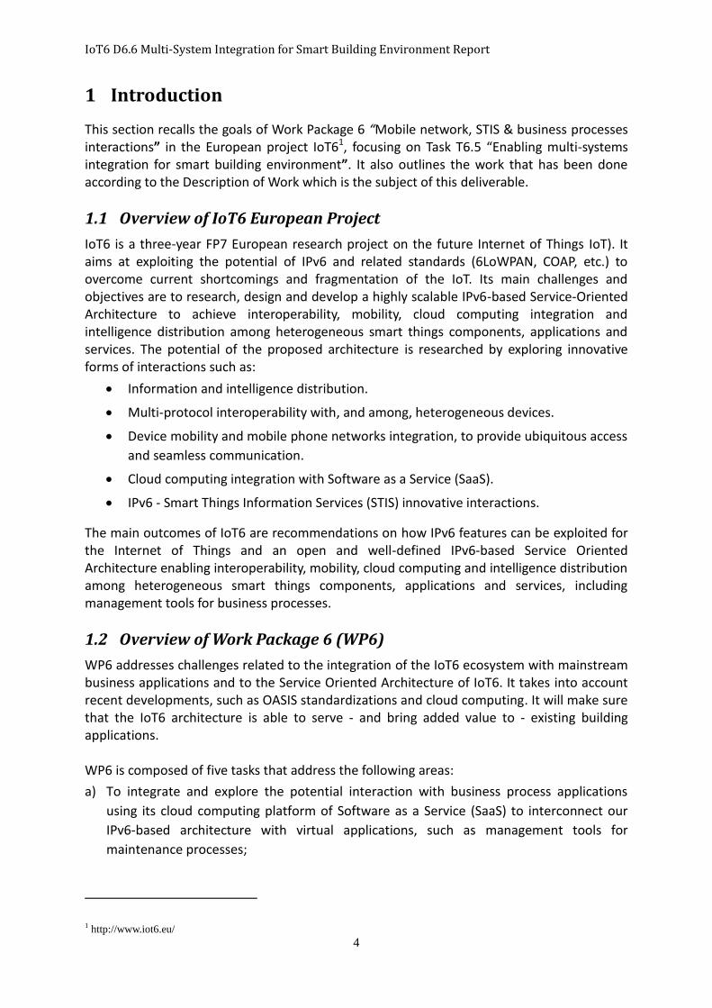
Figure 1: Primary Use Cases
Figure 1 illustrates the primary Use Cases envisaged by studying the problem description. The problem to solve is how to integrate two different worlds (IoT6 and Building Applications) in a common environment. To integrate means that all the participating entities should be able to communicate between one another and that every entity should understand the information sent between them.
2.2.2 Glossary
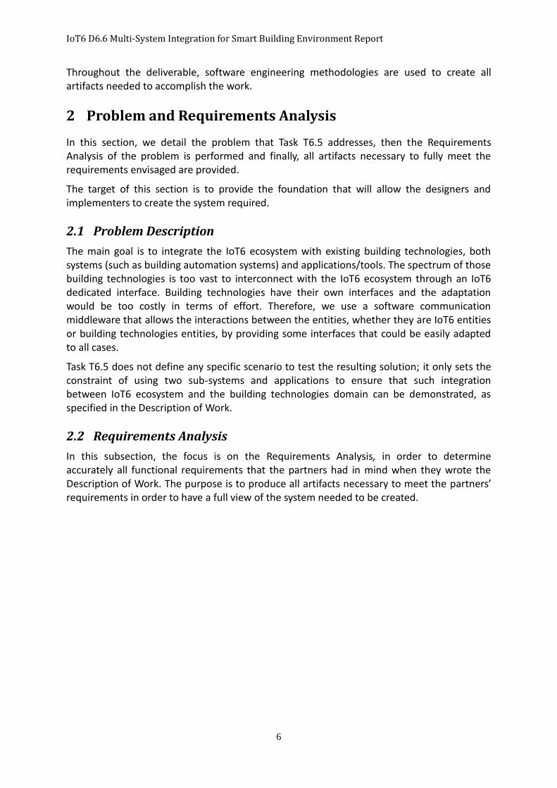
By using the problem description and the primary Use Cases, a glossary has been written, in which the most significant terms used are listed.
Term Meaning IoT6 Entity An entity belonging to the IoT6 ecosystem. Entity An entity, either software or hardware. Message The information that can be sent from an entity sender to an entity
receiver, in order to perform some tasks; It can be an IoT6 message or a building message.
MessageManager A component that manages the messages forwarding. Data The real content of the message. Translator A component that translate the messages from proprietary format (e.g.
IoT6 format or building applications formats) in an interpretable format. Connection The action of connecting two entities (or IoT6 or Building) in order to
allow them to communicate exchanging data. ConnectionManager A component that creates the connections among Entities. Middleware The communication media that is used to exchange data.
Table 1: Glossary
IoT6 D6.6 Multi-System Integration for Smart Building Environment Report
8
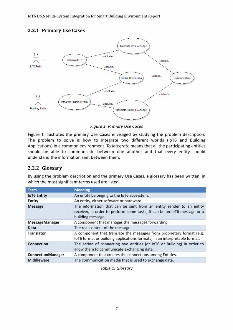
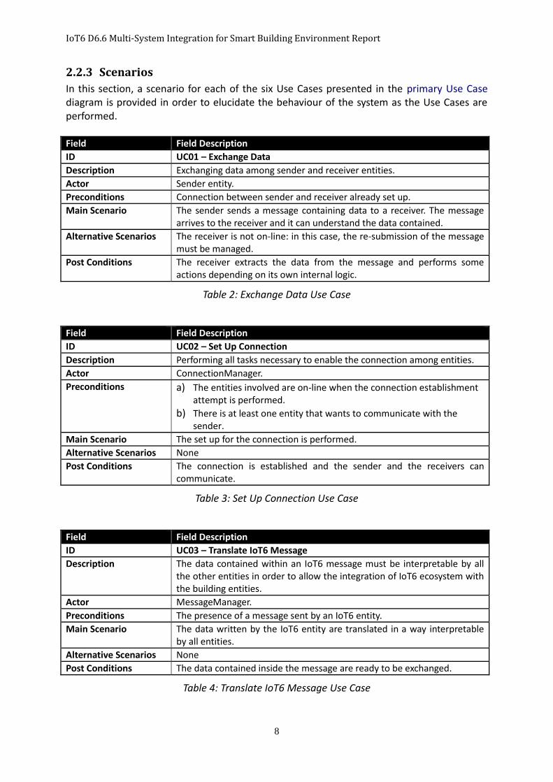
2.2.3 Scenarios
In this section, a scenario for each of the six Use Cases presented in the primary Use Case diagram is provided in order to elucidate the behaviour of the system as the Use Cases are performed. Field Field Description ID UC01 – Exchange Data Description Exchanging data among sender and receiver entities. Actor Sender entity. Preconditions Connection between sender and receiver already set up. Main Scenario The sender sends a message containing data to a receiver. The message
arrives to the receiver and it can understand the data contained. Alternative Scenarios The receiver is not on-line: in this case, the re-submission of the message
must be managed. Post Conditions The receiver extracts the data from the message and performs some
actions depending on its own internal logic.
Table 2: Exchange Data Use Case
Field Field Description ID UC02 – Set Up Connection Description Performing all tasks necessary to enable the connection among entities. Actor ConnectionManager. Preconditions a) The entities involved are on-line when the connection establishment
attempt is performed. b) There is at least one entity that wants to communicate with the
sender. Main Scenario The set up for the connection is performed. Alternative Scenarios None Post Conditions The connection is established and the sender and the receivers can
communicate.
Table 3: Set Up Connection Use Case
Field Field Description ID UC03 – Translate IoT6 Message Description The data contained within an IoT6 message must be interpretable by all
the other entities in order to allow the integration of IoT6 ecosystem with the building entities.
Actor MessageManager. Preconditions The presence of a message sent by an IoT6 entity. Main Scenario The data written by the IoT6 entity are translated in a way interpretable
by all entities. Alternative Scenarios None Post Conditions The data contained inside the message are ready to be exchanged.
Table 4: Translate IoT6 Message Use Case
IoT6 D6.6 Multi-System Integration for Smart Building Environment Report
9
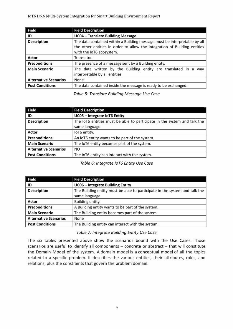
Field Field Description ID UC04 – Translate Building Message Description The data contained within a Building message must be interpretable by all
the other entities in order to allow the integration of Building entities with the IoT6 ecosystem.
Actor Translator. Preconditions The presence of a message sent by a Building entity. Main Scenario The data written by the Building entity are translated in a way
interpretable by all entities. Alternative Scenarios None Post Conditions The data contained inside the message is ready to be exchanged.
Table 5: Translate Building Message Use Case
Field Field Description ID UC05 – Integrate IoT6 Entity Description The IoT6 entities must be able to participate in the system and talk the
same language. Actor IoT6 entity. Preconditions An IoT6 entity wants to be part of the system. Main Scenario The IoT6 entity becomes part of the system. Alternative Scenarios NO Post Conditions The IoT6 entity can interact with the system.
Table 6: Integrate IoT6 Entity Use Case
Field Field Description ID UC06 – Integrate Building Entity Description The Building entity must be able to participate in the system and talk the
same language. Actor Building entity. Preconditions A Building entity wants to be part of the system. Main Scenario The Building entity becomes part of the system. Alternative Scenarios None Post Conditions The Building entity can interact with the system.
Table 7: Integrate Building Entity Use Case
The six tables presented above show the scenarios bound with the Use Cases. Those scenarios are useful to identify all components – concrete or abstract – that will constitute the Domain Model of the system. A domain model is a conceptual model of all the topics related to a specific problem. It describes the various entities, their attributes, roles, and relations, plus the constraints that govern the problem domain.
IoT6 D6.6 Multi-System Integration for Smart Building Environment Report
10
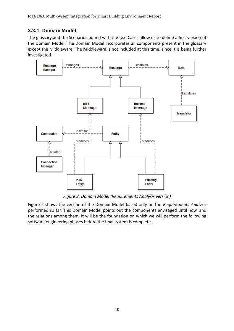
2.2.4 Domain Model
The glossary and the Scenarios bound with the Use Cases allow us to define a first version of the Domain Model. The Domain Model incorporates all components present in the glossary except the Middleware. The Middleware is not included at this time, since it is being further investigated.
Figure 2: Domain Model (Requirements Analysis version)
Figure 2 shows the version of the Domain Model based only on the Requirements Analysis performed so far. This Domain Model points out the components envisaged until now, and the relations among them. It will be the foundation on which we will perform the following software engineering phases before the final system is complete.
IoT6 D6.6 Multi-System Integration for Smart Building Environment Report
11
3 Technologies used for the Project
3.1 Distributed Middleware
Distributed communication paradigms [1] focus on freeing the components from system communication problems (abstracting the common problems). Over the years, various paradigms have been proposed and implemented; these paradigms follow either one-to-one or one-to-many (group) communication patterns, and each one provides different levels of abstraction and various features. Over time, various distributed paradigms were defined; Message Passing, Remote Procedure Calls, Notifications, Shared Spaces, Message Queuing and Publish/Subscribe are the most well-known. Such paradigms, given their different approaches, were adopted for different Use Cases, depending upon the services that were requested. The most interesting current feature for the new architectures, with respect to the communication domain, is the decoupling of the participating entities. Indeed, the entities’ presence, their locations and their active participation to the scenario can vary over time. The rate of decoupling that can be assigned to each paradigm depends on the time, space and synchronism decoupling they can provide. In the last years, the Publish/Subscribe paradigm emerged to be the best choice for systems that comprehend huge numbers of dynamic components that want to communicate and interact, due to its three dimensional (type, space and synchronism) decoupling. After a careful analysis, the Publish/Subscribe paradigm was agreed and decided upon as the software middleware solution for our system.
3.1.1 Publish/Subscribe
The Publish/Subscribe (P/S) paradigm [2] claims to provide the interactions schema that fits properly for large scale settings where strong loose decoupling is required, by providing entities that can abstract the participants from communication issues. This paradigm provides two main entities: Publisher – to provide data and Subscribers – to consume data. Each participant can play either the role of a publisher or the role of a subscriber, or both, depending on whether they want to provide or to consume data. The Publish/Subscribe pattern model provides three different kinds of decoupling:
Space Decoupling: The interacting components do not need to know the spatial position
of the entities they will interact with;
Time Decoupling: The interacting components do not need to be actively participating in
the interaction at the same time (i.e., if the Subscriber entities are off-line when some
interesting data is provided, they will receive it anyway when they are on-line again);
Synchronization Decoupling: Publishers are not kept waiting while they are producing
events and subscribers can be asynchronously notified of the occurrence of an event
while they are performing some concurrent activities.
Before the exchange of information starts, some tasks must be performed in the architecture in order to couple sources and destinations of data: the Publisher entities must notify the information they want to make available; the Subscribers must request the information they want to consume; the architecture must associate requests to notifications based on the events or the event patterns on which the requesters are interested. Various implementations of this paradigm handle the coupling tasks in different ways, but the two widely used coupling schematics are the so called Topic-Based and Context-Based.
In the Topic-Based schematic, the published events are categorized in topics using some

IoT6 D6.6 Multi-System Integration for Smart Building Environment Report
12
keywords. By doing so, some groups can arise, and the subscribers can unsubscribe themselves using the related keywords in order to subscribe to the interested topic. Afterwards, when an event is published on a topic, that event will be broadcasted to all subscribers.
Instead, in the Context-Based schematic, the events must possess some information related to their real content. The information specified by the publishers may be either internal attributes of the data the events are carrying, or may be some meta-data associated with the events. The subscribers show their interest in the events by using a subscription language and by specifying some filters in order to specify the data they are interested in. Subscription algorithms perform the association between the information connected to the events and the filters specified, allowing the dispatching of data from the sources to the consumers.
3.1.1.1 Orion Context Broker
Once the adequate paradigm for the middleware needed in our system was decided, the requirement of investigating the middleware solution had been accomplished. Afterwards, we started to look how to implement it, in order to re-use existing software and to focus on other functional requirements expressed in Task T6.5.
An interesting solution created within the FI-WARE 2 European project was discovered. This solution is well aligned with our ecosystem with respect to the technologies used. The goal of the FI-PPP FI-WARE project is to advance the global competitiveness of the EU economy by introducing an innovative infrastructure for cost-effective creation and delivery of services, providing high QoS and security guarantees. FI-WARE is designed to meet the demands of key market stakeholders across many different sectors, e.g., healthcare, telecommunications, and environmental services. This infrastructure is based on Generic Enablers (GEs), which provide utilities that implement some common capabilities and which can be re-used in other projects, singly or combined among them.
The Publish/Subscribe solution implemented for the FI-WARE project, called Orion Context Broker3 , uses the REST architecture and RESTful web services to provide functionalities and JSON as the format to exchange information, exactly as is done in the IoT6 ecosystem stack.
Since the idea behind the FI-WARE project is to provide software modules that accomplish some frequent tasks, by providing an abstraction layer that eases the fulfilment of the work, we decided to use it inside our solution.
The Orion Context Broker is an implementation of the Publish/Subscribe Context Broker GE that provides the NGSI94 and NGSI105 interfaces. Using these interfaces, clients can fulfil several operations:
Register context producer applications, e.g. a temperature sensor within a room;
Update context information, e.g. send updates of temperature;
Be notified when changes about context information take place (e.g. the temperature has changed) or with a given frequency (e.g. get the temperature each minute);
2 www.fi-ware.org 3 http://catalogue.fi-ware.org/enablers/publishsubscribe-context-broker-orion-context-broker 4 http://forge.fi-ware.org/plugins/mediawiki/wiki/fiware/index.php/FI-WARE_NGSI-9_Open_RESTful_API_Specification 5 http://forge.fi-ware.org/plugins/mediawiki/wiki/fiware/index.php/FI-WARE_NGSI-10_Open_RESTful_API_Specification
IoT6 D6.6 Multi-System Integration for Smart Building Environment Report
13
Query context information - The Orion Context Broker stores context information updated from applications, so queries are resolved based on that context information.
3.2 IoT6 Ecosystem
The IoT6 Ecosystem represents the set of all components created and deployed within the IoT6 project. To interconnect these components under a common communication environment, the partners of the IoT6 project have been designing a common interface. This interface, named IoT6 stack, defines the standards to which all entities that want to exchange information inside the IoT6 ecosystem must comply.
3.2.1 IoT6 Stack
The IoT6 stack aims to provide a common communication interface amongst all technologies present in the Internet of Things environment. The core elements of the IoT6 stack are: IPv6 as Internet Protocol, Web services based on CoAP 6 as a service layer, the OASIS Open Building Information Exchange standard (oBIX) [3] as object model and JSON7 as message encoding.
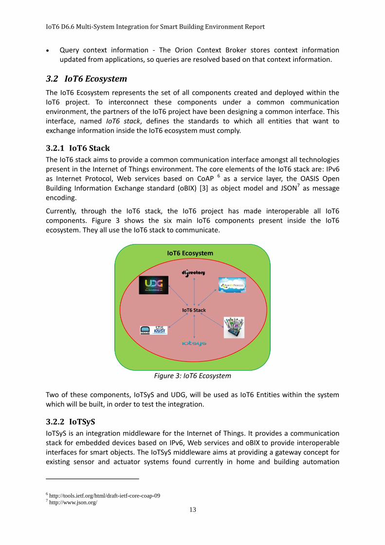
Currently, through the IoT6 stack, the IoT6 project has made interoperable all IoT6 components. Figure 3 shows the six main IoT6 components present inside the IoT6 ecosystem. They all use the IoT6 stack to communicate.
Figure 3: IoT6 Ecosystem
Two of these components, IoTSyS and UDG, will be used as IoT6 Entities within the system which will be built, in order to test the integration.
3.2.2 IoTSyS
IoTSyS is an integration middleware for the Internet of Things. It provides a communication stack for embedded devices based on IPv6, Web services and oBIX to provide interoperable interfaces for smart objects. The IoTSyS middleware aims at providing a gateway concept for existing sensor and actuator systems found currently in home and building automation
6 http://tools.ietf.org/html/draft-ietf-core-coap-09 7 http://www.json.org/
IoT6 D6.6 Multi-System Integration for Smart Building Environment Report
14
systems. The gateway provides interfaces according to the IoT6 stack for several existing state-of-the art technologies, which are non-IPv6 based. It has a common interface to provide direct browser-based interaction with these devices, allowing them to be integrated with control and monitoring systems, Cloud-based software-as-a-service, and global discovery services and to be interfaced through mobile computing.
Multiple HTTP and CoAP handlers are offered and bound to virtual and physical network interfaces. An HTTP and a CoAP handler can be used to offer a centralized interface conforming to the traditional oBIX approach to interact with devices. In case of HTTP, this is fully compliant to the oBIX standard, at the same time per-device interfaces can be offered with HTTP and CoAP. The HTTP interfaces remain oBIX compliant and the CoAP interfaces are compliant to the CoRE standards.
The message encoding and decoding are accomplished transparently between the HTTP and CoAP handlers and the oBIX server. As encoding XML, JSON, EXI or oBIX binary encoding can be used to encode the transferred oBIX objects.
3.2.3 Universal Device Gateway (UDG)
Universal Device Gateway (UDG) is an IPv6-compliant multi-protocol control and monitoring system developed in a previous project and adapted to the IoT6 project requirements. It can be used as a gateway enabling the management of the exchanging of information among heterogeneous systems and components, including Building Automation Systems using different communication protocols. UDG is composed of two parts: the first part is a middleware that manages the sending of actions and the receiving of events from the devices; the second part is a Control and Monitoring System that manages the scenarios’ business logic defined by users. It provides HTTP and CoAP web services for incoming communication.
3.3 Smart Building Applications
The main task to accomplish in Task T6.5 is to integrate Building Entities with the IoT6 ecosystem. Since the software middleware solution has now been decided, we must now choose some interesting Building Entities which we want to interconnect to the IoT6 ecosystem.
“Building automation is the goal that a Building Management System or a (more recent terminology) Building Automation System (BAS) attempts to achieve. Both are examples of a distributed control system - the computer networking of electronic devices designed to monitor and control the mechanical, security, fire and flood safety, lighting (especially emergency lighting), HVAC and humidity control and ventilation systems in a building.”8
Beginning with this definition of what is a Building Application, technologies correlating with both the physical and application world were chosen. The list of chosen technologies depends on an awareness of the mainstream technologies currently in wide use in the building domain, or which of these technologies can produce the most significant impact.
For the physical world, Microsoft Kinect9 as a movement captor and Philips Hue10 as a lights
8 http://www.kmccontrols.com/products/Understanding_Building_Automation_and_Control_Systems.aspx 9 http://en.wikipedia.org/wiki/Kinect 10 http://meethue.com/
IoT6 D6.6 Multi-System Integration for Smart Building Environment Report
15
actuator and the XBee brightness sensor11 to catch the brightness changes in a room were chosen. For the application world, our choices fell on: the Google Spreadsheet12, which shares interesting information in an easy way; mobile applications, specifically the Android environment, since now almost everyone has a mobile phone and, moreover, connecting mobiles through our IoT6 ecosystem could be a fascinating feature and Google Glass13, to explore how we can command and visualize the information needed using this interesting emerging technology.
3.3.1 Microsoft Kinect for Windows
Kinect is a line of motion-sensing input devices created by Microsoft for Xbox and Xbox360. Based around a webcam-style add-on peripheral, it enables users to control and interact with their console/computer without the need for a game controller, through a natural user interface using gestures and spoken commands.
3.3.2 Philips Hue (Personal Wireless Lighting)
Philips Hue is a technology of fully customizable, managed light bulbs, offering a choice of 16 million colors by combining three LEDs — one green, one red, and one blue - inside each bulb. These light bulbs are being marketed as energy-efficient alternatives to regular light bulbs, with brightness equivalent to a traditional 50W bulb with a maximum power draw of just 8.5W.
3.3.3 XBee Temperature and Brightness Sensor
XBee Sensors are compact, battery powered environmental sensors for ZigBee networks. They provide real-time temperature and light information for a variety of applications including building automation and security, energy management, food management, freight and vehicle monitoring, and many more.
3.3.4 Android App
An Android app is a software application running on the Android platform. The Android platform is built for mobile devices, while a typical Android app is designed for a Smartphone or a tablet PC running on the Android OS.
Android apps are written in the Java programming language and use Java core libraries. They are first compiled to Dalvik executables to run on the Dalvik virtual machine, which is a virtual machine specifically designed for mobile devices, then installed on devices to be used.
3.3.5 Google Glass
Google Glass is a wearable computer with an optical head-mounted display (OHMD). It was developed by Google with the mission of producing a mass-market ubiquitous computer. Google Glass displays information in a Smartphone-like hands-free format. Wearers communicate with the Internet via natural language voice commands.
11 http://www.digi.com/products/wireless-modems-peripherals/wireless-range-extenders-peripherals/xbee-sensors 12 https://en.wikipedia.org/wiki/Google_docs 13 http://en.wikipedia.org/wiki/Google_Glass

IoT6 D6.6 Multi-System Integration for Smart Building Environment Report
16
3.3.6 Google SpreadSheet
Google Docs is a free, web-based office suite offered by Google within its Google Drive service. It allows users to create and edit documents online while collaborating with other users live. Google Docs serves as a collaborative tool for editing documents in real time. Documents can be shared, opened, and edited by multiple users simultaneously. Google Docs is one of many cloud computing document-sharing services. We use the Google Spreadsheet utility of Google Docs.
4 Problem Analysis
In this section, the problems envisaged in Section 2.1 are analyzed. This section describes the scenarios and the Domain Model of the entities and the interactions between them. The aim of this section is to define a Logical Architecture, based on the Domain Model, of the system that needs to be modelled. This Logical Architecture will consider all components that come into play in the system, such as the behavior expected by each component, the union of all the components together, their interactions and it will describe its full structure, without considering any specific technology and without letting our decisions be influenced by the chosen Building Application.
We will analyze the problem in three dimensions: the Structure dimension that describes how the components of the system are organized, the Interactions dimension that describes the fundamental communication between components, and the Behavior dimension that describes how each component behaves.
4.1 Structure Dimension
The Requirements Analysis highlighted the following main Use Cases needed to accomplish the integration of IoT6 ecosystem and Building Applications under a common communication middleware:
UC01 - Exchange Data
UC02 - Set Up Connection
UC03 - Translate IoT6 Message
UC04 - Translate Building Message
UC05 – Integrate IoT6 Entity
UC06 – Integrate Building Entity
Following the approach proposed by Jacobson [4] , the components included in the Domain Model were divided into three groups that represent different vertical dimensions, labeled: Entity, Boundary and Control. Entity: Contains the concrete components which will be used by other components and is considered as the central point of the project that explains why we have to build a system. The following list itemizes the components belonging to the Entity group:
Message
o IoT Message

IoT6 D6.6 Multi-System Integration for Smart Building Environment Report
17
o Building Message
Data
Connection
Boundary: Contains the components that encapsulate the interfaces of the system towards the external world. The following list itemizes the components belonging to the Boundary group:
Entity
o IoT Entity
o Building Entity
Control: This is the principal group, and contains the components that mediate between the Boundary and Entity in order to perform the business logic of our system. The following list itemizes the components belonging to the Control group:
ConnectionManager
Translator
MessageManager
The next task is to connect the components in the Domain Model with the Use Cases, creating a high level view of the Logical Architecture that displays the structural aspects of the system and points out the dependencies between and among components and Use Cases.
Figure 4: Logical Architecture (High Level View)
Figure 4 shows how the components are correlated with Use Cases (black arrows) and the dependencies between components (red arrows) that have been envisaged so far.
IoT6 D6.6 Multi-System Integration for Smart Building Environment Report
18
In the next subsections, all the correlations and dependencies are analyzed in detail.
4.2 Interactions Dimension
The red arrows in Figure 4 highlight the dependencies that are envisaged among the components present in our architecture. Now, we must understand which of these are relevant, in order to identify the most appropriate interaction modalities to be applied to those dependencies. The following list itemizes the meaningful dependencies needed to accomplish the building logic of the system:
Entity – ConnectionManager
Entity – MessageManager
MessageManager – Translator
Some dependencies have been taken out of the list since they are not meaningful within the context of the business logic model. Once the relevant dependencies have been identified, the nature of the system must now be decided. This implies determining whether the system should be either a full local one, or have some distributed components, or be fully distributed. The environment in which the system will be applied leans towards a distributed direction based on the requirements’ definition since it is composed of distributed heterogeneous entities that want to use a middleware in order to exchange information. The solution chosen was one in which a central system will simulate a fully distributed environment providing a set of interfaces that will be replicated on all nodes that represent external entities. Those interfaces will allow the entities to be part of the system and communicate among them seamlessly.
4.2.1 Interactions Definition
Besides the nature of the system and its dependencies, the communications mode which will be used to model the interactions must now be chosen. All interactions will be defined by identifying which ones are the Producer and the Consumer and what kind of communication mode will be used. The interfaces will be considered in addition, and not as components, highlighting how they interact between them. Prior to making any decision about the communication mode, the main forms of communications are listed below. The most appropriate form will be chosen in order to model our interactions.
Event: Information sent by a sender in an asynchronous way. The sender does not know
the receiver and it does not know its behavior after the receipt of the information.
Signal: Information sent by a sender in an asynchronous way to more receivers. The
sender can know or not know the receivers, but it expects that at least one receiver will
receive the information.
Dispatch: Information sent by a sender in an asynchronous way to a specific receiver.
The sender does not expect any answers, but it expects that the receiver receives the
information and elaborates on it as intended.
IoT6 D6.6 Multi-System Integration for Smart Building Environment Report
19
Invitation: Information sent by a sender to more receivers. The sender expects that at
least one receiver will receive the information and the receiver will send back an
acknowledgment.
Request: Information sent by a sender to a specific receiver. The sender expects that the
receiver receives the information, elaborates on it as intended and sends a pertinent
response back.
4.2.1.1 Entity – ConnectionManager
An Entity depends on a ConnectionManager in order to be connected to the system and to exchange information with other entities. Therefore, this interaction starts from the Entity and goes towards the ConnectionManager. This leads to the following Producer – Consumer decision:
Producer: Entity
Consumer: ConnectionManager
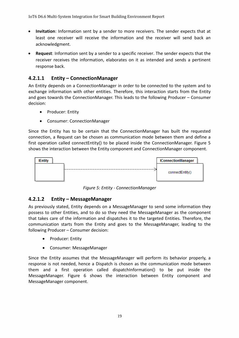
Since the Entity has to be certain that the ConnectionManager has built the requested connection, a Request can be chosen as communication mode between them and define a first operation called connectEntity() to be placed inside the ConnectionManager. Figure 5 shows the interaction between the Entity component and ConnectionManager component.
Figure 5: Entity - ConnectionManager
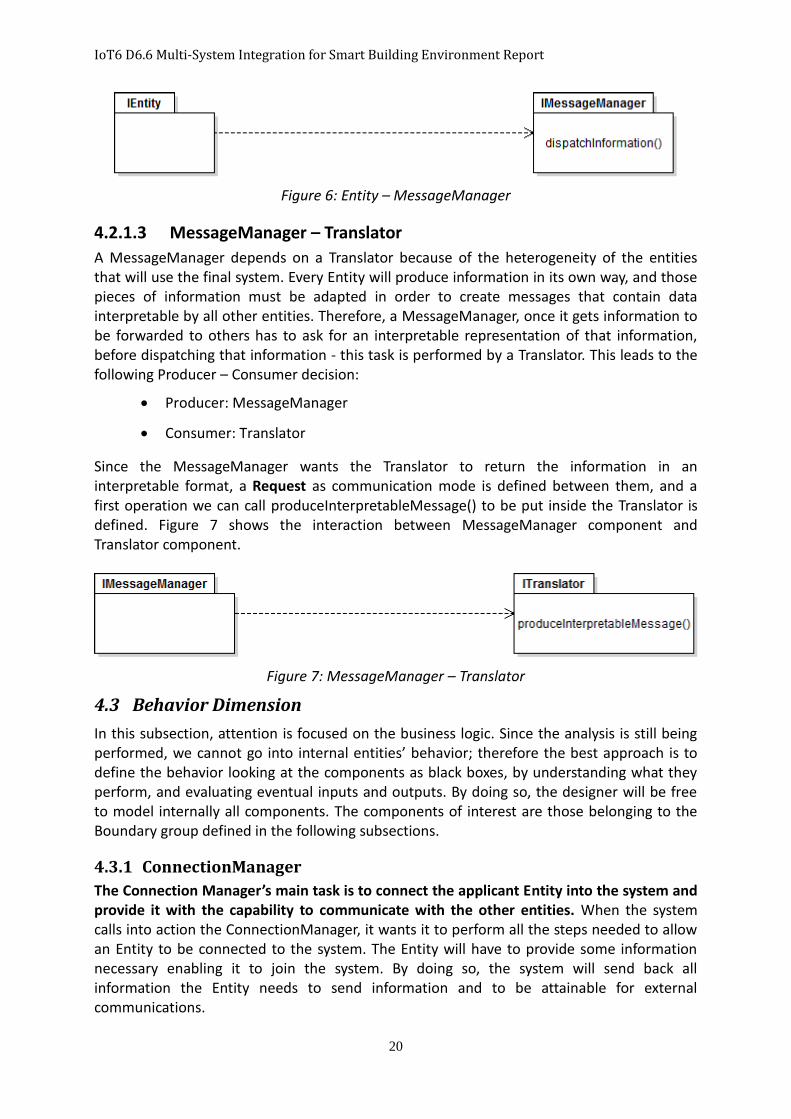
4.2.1.2 Entity – MessageManager
As previously stated, Entity depends on a MessageManager to send some information they possess to other Entities, and to do so they need the MessageManager as the component that takes care of the information and dispatches it to the targeted Entities. Therefore, the communication starts from the Entity and goes to the MessageManager, leading to the following Producer – Consumer decision:
Producer: Entity
Consumer: MessageManager
Since the Entity assumes that the MessageManager will perform its behavior properly, a response is not needed, hence a Dispatch is chosen as the communication mode between them and a first operation called dispatchInformation() to be put inside the MessageManager. Figure 6 shows the interaction between Entity component and MessageManager component.
IoT6 D6.6 Multi-System Integration for Smart Building Environment Report
20
Figure 6: Entity – MessageManager
4.2.1.3 MessageManager – Translator
A MessageManager depends on a Translator because of the heterogeneity of the entities that will use the final system. Every Entity will produce information in its own way, and those pieces of information must be adapted in order to create messages that contain data interpretable by all other entities. Therefore, a MessageManager, once it gets information to be forwarded to others has to ask for an interpretable representation of that information, before dispatching that information - this task is performed by a Translator. This leads to the following Producer – Consumer decision:
Producer: MessageManager
Consumer: Translator
Since the MessageManager wants the Translator to return the information in an interpretable format, a Request as communication mode is defined between them, and a first operation we can call produceInterpretableMessage() to be put inside the Translator is defined. Figure 7 shows the interaction between MessageManager component and Translator component.
Figure 7: MessageManager – Translator
4.3 Behavior Dimension
In this subsection, attention is focused on the business logic. Since the analysis is still being performed, we cannot go into internal entities’ behavior; therefore the best approach is to define the behavior looking at the components as black boxes, by understanding what they perform, and evaluating eventual inputs and outputs. By doing so, the designer will be free to model internally all components. The components of interest are those belonging to the Boundary group defined in the following subsections.
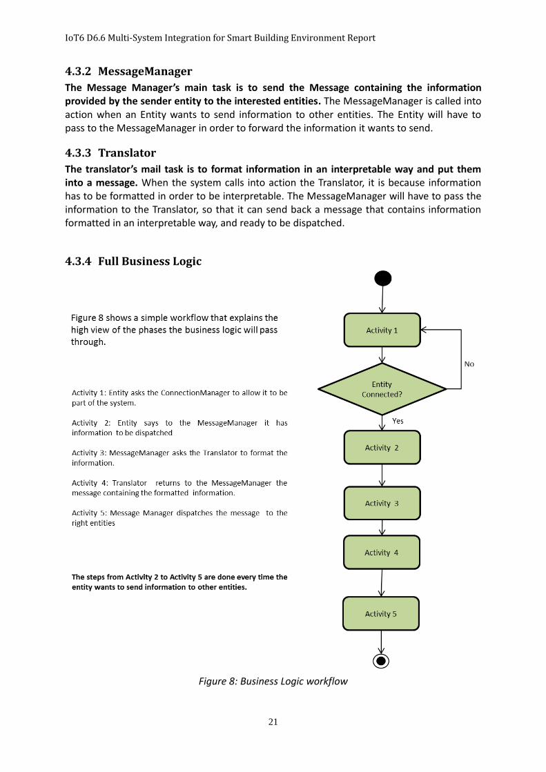
4.3.1 ConnectionManager
The Connection Manager’s main task is to connect the applicant Entity into the system and provide it with the capability to communicate with the other entities. When the system calls into action the ConnectionManager, it wants it to perform all the steps needed to allow an Entity to be connected to the system. The Entity will have to provide some information necessary enabling it to join the system. By doing so, the system will send back all information the Entity needs to send information and to be attainable for external communications.
IoT6 D6.6 Multi-System Integration for Smart Building Environment Report
21
4.3.2 MessageManager
The Message Manager’s main task is to send the Message containing the information provided by the sender entity to the interested entities. The MessageManager is called into action when an Entity wants to send information to other entities. The Entity will have to pass to the MessageManager in order to forward the information it wants to send.
4.3.3 Translator
The translator’s mail task is to format information in an interpretable way and put them into a message. When the system calls into action the Translator, it is because information has to be formatted in order to be interpretable. The MessageManager will have to pass the information to the Translator, so that it can send back a message that contains information formatted in an interpretable way, and ready to be dispatched.
4.3.4 Full Business Logic
Figure 8: Business Logic workflow

IoT6 D6.6 Multi-System Integration for Smart Building Environment Report
22
5 Design
In this section, the Logical Architecture is refined in order to define the set of functional system parts (functions, classes, objects, and components) and the set of relationships between those parts. In the design phase, the specific technologies to be used are identified.
5.1 Orion Context Broker & Logical Architecture
The system which is being developed was conceived to be built around a software middleware solution that allows the exchange of information between heterogeneous entities scattered in a distributed environment. We chose the Orion Context Broker to accomplish this purpose. Orion Context Broker is a middleware solution that implements the Publish/Subscribe paradigm. It possesses all features imposed by the Publish/Subscribe specification, and some additional ones which will not be considered. In the next subsections, we will detail how the Orion Context Broker is composed and explain the features which will be used.
5.1.1 Introduction to the Orion Context Broker
The Orion Context Broker enables publisher entities (Context information Producers) to publish context information, so that it becomes available to other entities (called Context information Consumers) interested in it. Applications can play the role of Context Producers, Context Consumers, or both.
The Orion Context Broker supports two ways of communications: Push and Pull. Push communication means that a Context Producer can continuously push the context information into the Orion Context Broker. Pull communication means that the Orion Context Broker on its side can request the context information to Context Producers if they provide the ability to be queried (in this case Context Producers act as Context Providers). In a similar way, Context Consumers can pull the context information from the Context Broker (on-request mode), or the Context Broker can push the information to Contest Consumers interested in it (subscription mode).
The Orion Context Broker achieves the full decoupling demanded by the Publish/Subscribe paradigm. As a consequence, it is an excellent bridge enabling external applications to manage events related to the Internet of the Things (IoT) in a simple way. It achieves this by hiding the complexity of gathering measures from IoT resources (sensors) that might be distributed or involving access through multiple low-level communication protocols. 14
5.1.2 FI-WARE NGSI Specification
Most of the FI-WARE Generic Enablers’ (GEs') API operations regarding Events/Context retrieval and notification are inspired by the OMA (Open Mobile Alliance) NGSI Context Management specifications [5].
Furthermore the FI-WARE team has identified potential updates to the standard to guarantee its correct exploitation in this context, to solve some ambiguities and to extend its capabilities according to the FI-WARE vision. FI-WARE NGSI specifications differ from the OMA NGSI specifications mainly in the binding, as far as OMA does not have any binding by
14 http://forge.fi-ware.org/plugins/mediawiki/wiki/fiware/index.php/FIWARE.OpenSpecification.Data.PubSub
IoT6 D6.6 Multi-System Integration for Smart Building Environment Report
23
definition. Moreover FI-WARE NGSI improves some of the OMA NGSI aspects. Therefore, the FI-WARE NGSI is essentially the technological binding for the OMA specifications, with very few omissions and differences from it.
5.1.2.1 FI-WARE NGSI-915
The FI-WARE version of the OMA NGSI-9 interface is a RESTful API via HTTP. Its purpose is to exchange information about the availability of context information. The three main operations to exchange information types are:
1. One-time queries, for discovering hosts (agents) where certain context information is available;
2. Subscriptions for context availability information updates (and the corresponding notifications);
3. Recordings of context information, i.e. announcements about the availability of certain context information (invoked by context providers).
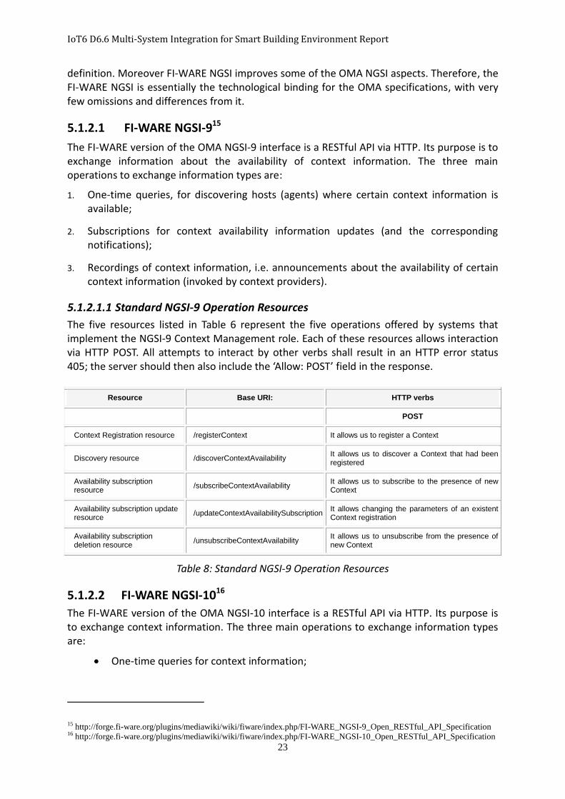
5.1.2.1.1 Standard NGSI-9 Operation Resources
The five resources listed in Table 6 represent the five operations offered by systems that implement the NGSI-9 Context Management role. Each of these resources allows interaction via HTTP POST. All attempts to interact by other verbs shall result in an HTTP error status 405; the server should then also include the ‘Allow: POST’ field in the response.
Resource Base URI: HTTP verbs
POST
Context Registration resource /registerContext It allows us to register a Context
Discovery resource /discoverContextAvailability It allows us to discover a Context that had been registered
Availability subscription resource
/subscribeContextAvailability It allows us to subscribe to the presence of new Context
Availability subscription update resource
/updateContextAvailabilitySubscription It allows changing the parameters of an existent Context registration
Availability subscription deletion resource
/unsubscribeContextAvailability It allows us to unsubscribe from the presence of new Context
Table 8: Standard NGSI-9 Operation Resources
5.1.2.2 FI-WARE NGSI-1016
The FI-WARE version of the OMA NGSI-10 interface is a RESTful API via HTTP. Its purpose is to exchange context information. The three main operations to exchange information types are:
One-time queries for context information;
15 http://forge.fi-ware.org/plugins/mediawiki/wiki/fiware/index.php/FI-WARE_NGSI-9_Open_RESTful_API_Specification 16 http://forge.fi-ware.org/plugins/mediawiki/wiki/fiware/index.php/FI-WARE_NGSI-10_Open_RESTful_API_Specification

IoT6 D6.6 Multi-System Integration for Smart Building Environment Report
24
Subscriptions for context information updates (and the corresponding
notifications);
Unsolicited updates (invoked by context providers).
5.1.2.2.1 Standard NGSI-10 Operation Resources
The five resources listed in Table 7 represent the five operations offered by systems that implement the NGSI-10 Context Management role. Each of these resources allows interaction via HTTP POST. All attempts to interact by other verbs shall result in an HTTP error status 405; the server should then also include the ‘Allow: POST’ field in the response.
Resource Base URI: HTTP verbs
POST
Context query resource /queryContext It allows us to ask Context information stored.
Subscribe context resource /subscribeContext It allows subscribing to Context information when something happens.
Update context subscription resource
/updateContextSubscription It allows changing the parameters of an existent subscription.
Unsubscribe context resource
/unsubscribeContext It allows unsubscribing to Context information we were subscribed to.
Update context resource /updateContext It allows to create (using APPEND as type action) or to update (using UPDATE as type action) an entity.
Table 9: Standard NGSI-10 Operation Resources
There are also Convenience Operation Resources defined by NGSI-9 and NGSI-10 specifications, but they will not be used in the system. Of the set of Standard Operation Resources provided by NGSI-9 and NGSI-10, those operations, showed in Table 10 in bold will be used since they are interesting for our system.
5.1.3 Data Format
The Orion Context Broker gives users two possibilities namely, XML and JSON to format the data they want to exchange, as they prefer. For our system, JSON will be used because it is also part of the IoT6 stack defined for the IoT6 ecosystem, with the advantage of simplifying the integration.
5.1.4 Logical Architecture including the Orion Context Broker
Figure 9 shows how the Orion Context Broker was integrated within the Logical Architecture previously defined, pointing out the changes regarding the dependences it brought. The Orion Context Broker manages the dispatching of information published from Publishers to Subscribers interested in that information. Since this information dispatching involves two use cases (Exchange Data (UC01) and Set-Up Connection (UC02)), we modeled the integration of the Orion Context Broker defining the dependencies between it and the MessageManager, the ConnectionManager and the Connection.

IoT6 D6.6 Multi-System Integration for Smart Building Environment Report
25
Figure 9: Logical Architecture including Orion Broker
5.1.5 Consequences brought by the Orion Context Broker
The introduction of the Orion Context Broker within the Logical Architecture brings some constraints, related to the technologies to be used, that limit the modeling freedom about interactions and architecture details. The Orion Context Broker is the software middleware used in this system to dispatch the information among the Entities, as presented in the previous subsection “FI-WARE NGSI Specification”. In our system, only a subset belonging to the NSGI-10 specification will be used. The operations used are shown in bold in the subsection “Standard NGSI-10 Operation Resources”: updateContext, queryContext, subscribeContext and unsubscribeContext. The Orion Context Broker is based on RESTful web services, so the first constraint is the forcing of the Entities to communicate with it through RESTful APIs. As a consequence, we must provide the Entities with web interfaces that use HTTP methods in order to communicate with it. A second constraint is the data format exchanged among the web interfaces and the Orion Context Broker. The Orion Context Broker allows two data formats: XML and JSON, and JSON will be used to maximize the compatibility of the Orion Context Broker with the IoT6 stack. For the Publisher Entities the constraints have been taken into account, but the other constraint concerning the Subscribers Entities still has to be implemented. The Orion Context Broker manages the dispatching of information to the Subscriber Entities through the HTTP POST method. This feature constrains the Subscriber Entities of being equipped with a web service interface in order to receive the information that the Orion Context Broker will dispatch to them. The constraints aforementioned will produce some effects in the design of the components defined in the Problem Analysis section.

IoT6 D6.6 Multi-System Integration for Smart Building Environment Report
26
5.2 Design of Entities
The Problem Analysis section demonstrated that the Entities, both for the IoT6 ecosystem and Building have characteristics in common, and can be designed under the same criteria. We will now clarify how they are involved in the three dimensions defined previously:
1. Structure: Entities play a role in interfacing the system with the external world. The external world refers to the real technologies used in this project;
2. Interaction: Entities interact directly with two components of the system – the ConnectionManager through a Request interaction and the MessageManager through a Dispatch interaction;
3. Behavior: The behavior of the Entities changes depending on whether they act as a Publisher or a Subscriber. In the case, an Entity acts as a Publisher, it will act as a Web Client that will communicate with the Orion Context Broker. However, if an Entity acts as a Subscriber, it will act both as a Web Client of the Orion Context Broker and as a Web Service that waits for incoming communications from the Orion Context Broker. Although the Publish/Subscribe paradigm contemplates only Publisher and Subscribe Entities, the Orion Context Broker provides the capability of requiring context information without being subscribed to them, but simply asking for them. Therefore, it was decided to model a Query Entity that will take care of this case.
Led by the aforementioned clarifications, we decided to model the Entity (IoT6 and Building) following the same logic. Figure 10 shows how the Entity problem was modeled using an Abstract class, followed by the three concrete classes that extend below the Abstract class i.e. Publisher, Subscriber and Query Entities. The action of performing the connection to the System is common to all Entities, and this is the reason why it will be performed by the Abstract class.
Figure 10: Model of Boundary Package

IoT6 D6.6 Multi-System Integration for Smart Building Environment Report
27
5.3 Design of ConnectionManager
In the Problem Analysis section, the ConnectionManager was identified as the component that allows the Entities to make the connection with the Orion Context Broker. In order for a connection to be established for both the Publisher Subscriber and Query Entities, a Web Resource is needed that allows the Entities to join the Orion Context Broker. Since the communication between the Entities and the ConnectionManager is defined as a Request interaction, when an Entity contacts the ConnectionManager, it will respond with a WebResource necessary to join the Orion Context Broker.
5.4 Design of MessageManager
In the Problem Analysis section, the MessageManager is defined as the component that should manage the creation of interpretable messages to be exchanged between the Entities and to dispatch those messages from Publishers to Subscribers. The integration of the Orion Context Broker brings a modification to this procedure, whereby the dispatching is not direct, but it is managed by the Orion Context Broker. Therefore, the MessageManager provides a publish interface that allows the entities to insert information in the Orion Context Broker. In regards to the creation of interpretable messages, nothing has changed. The MessageManager provides the interfaces needed by the Entities they have some well-formatted information ready to be sent. The Orion Context Broker requires a payload as argument of the HTTP POST method. These payloads can be seen as information that Entities send to the middleware. The payload required by HTTP POST methods will create some consequences when the Data component is modeled.
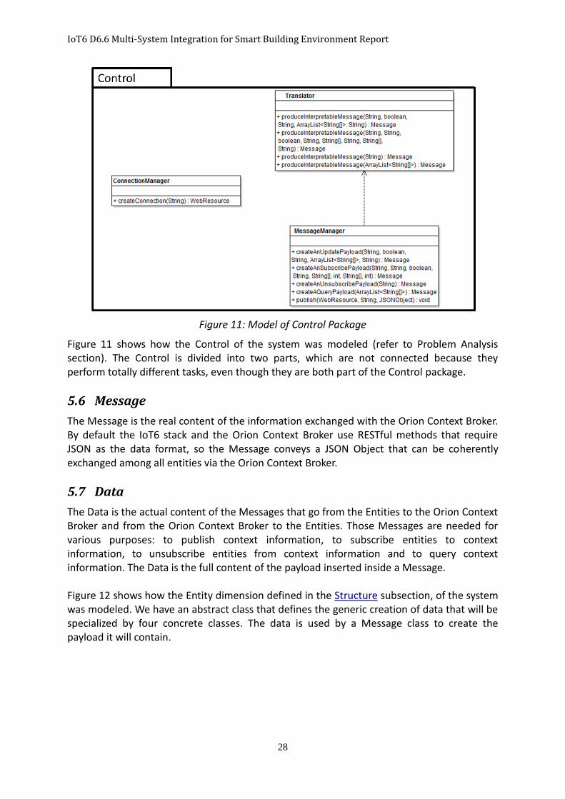
5.5 Design of Translator
In the Problem Analysis section, the Translator is defined as the component that should perform the creation of interpretable messages. It provides interfaces to allow the MessageManager to request the creation of messages containing a JSON Object as Data. This is requested in order to be compatible with the Orion Context Broker and the IoT6 stack, and to allow the interpretation of the messages everywhere within the system.
IoT6 D6.6 Multi-System Integration for Smart Building Environment Report
28
Figure 11: Model of Control Package
Figure 11 shows how the Control of the system was modeled (refer to Problem Analysis section). The Control is divided into two parts, which are not connected because they perform totally different tasks, even though they are both part of the Control package.
5.6 Message
The Message is the real content of the information exchanged with the Orion Context Broker. By default the IoT6 stack and the Orion Context Broker use RESTful methods that require JSON as the data format, so the Message conveys a JSON Object that can be coherently exchanged among all entities via the Orion Context Broker.
5.7 Data
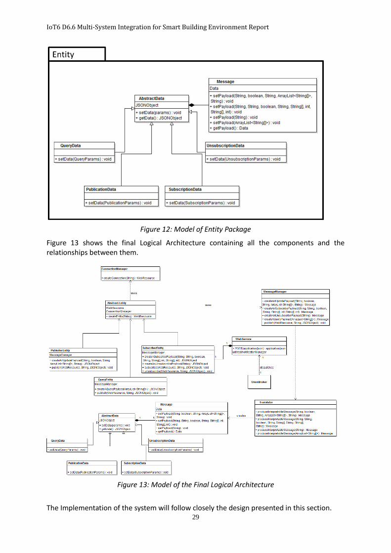
The Data is the actual content of the Messages that go from the Entities to the Orion Context Broker and from the Orion Context Broker to the Entities. Those Messages are needed for various purposes: to publish context information, to subscribe entities to context information, to unsubscribe entities from context information and to query context information. The Data is the full content of the payload inserted inside a Message. Figure 12 shows how the Entity dimension defined in the Structure subsection, of the system was modeled. We have an abstract class that defines the generic creation of data that will be specialized by four concrete classes. The data is used by a Message class to create the payload it will contain.
IoT6 D6.6 Multi-System Integration for Smart Building Environment Report
29
Figure 12: Model of Entity Package
Figure 13 shows the final Logical Architecture containing all the components and the relationships between them.
Figure 13: Model of the Final Logical Architecture
The Implementation of the system will follow closely the design presented in this section.
IoT6 D6.6 Multi-System Integration for Smart Building Environment Report
30
6 Scenario
This section introduces the scenario used to test the developed system. The scenario proposes a demonstration in a smart building environment, as required in the Description of Work. This scenario will use all components (IoT6 and Building) listed in the section Technologies used for the Project, in order to check the integration of Building Technologies with the IoT6 ecosystem. The scenario will demonstrate how our system can improve the comfort and the energy consumption of a hospital room that houses a patient.
6.1 Scenario Description
The scenario describes the management of the lighting in a hospital room that houses a patient who cannot use his or her arms. Two different scenarios are considered: regular mode situation and comfort mode situation. The regular mode is seen as the situation in which the management of the room lighting depends on the outside light conditions during the day. Depending on the perception of those conditions, the building system logic will perform the tasks explained in subsection 6.1.1. The comfort mode is seen as the situation where the management of the room lighting depends on the body movements of the patient during the evening. Depending on the perception of those movements, the building logic of the system will perform the tasks explained in subsection 6.1.3. During the regular mode situation, IoTSyS receives brightness information, which is used to decide to switch on or off the lights in the room, or put the shutters up or down. Meanwhile, Google Spreadsheet receives the same brightness information and will store the data for further research. Philips Lighting will start to manage the lights depending on the patient’s movements, which the UDG will monitor. The LED turned on by IoTSyS will let the nurse’s station know that the room is now in comfort mode, and, as a consequence, a nurse will enter the room and will take the Google Glass from the patient who is unable to use his/her arms. Now, all depends on Kinect which will provide the movements’ data that will trigger the Philips Lighting and the UDG’s behavior. In the case of an emergency, the UDG will launch an alarm for the hospital staff. Furthermore, an Android App allows the relatives of the patient to check if the room is in comfort mode or not, because when the room is in comfort mode phone calls are forbidden. The following subsections show the sequence diagram which describes in detail the scenario, and explains what happens in each state. Depending on the situation selected by the patient, the components will decide how to behave, as explained in the sequence diagram.
IoT6 D6.6 Multi-System Integration for Smart Building Environment Report
31
6.1.1 Regular Mode Situation Management
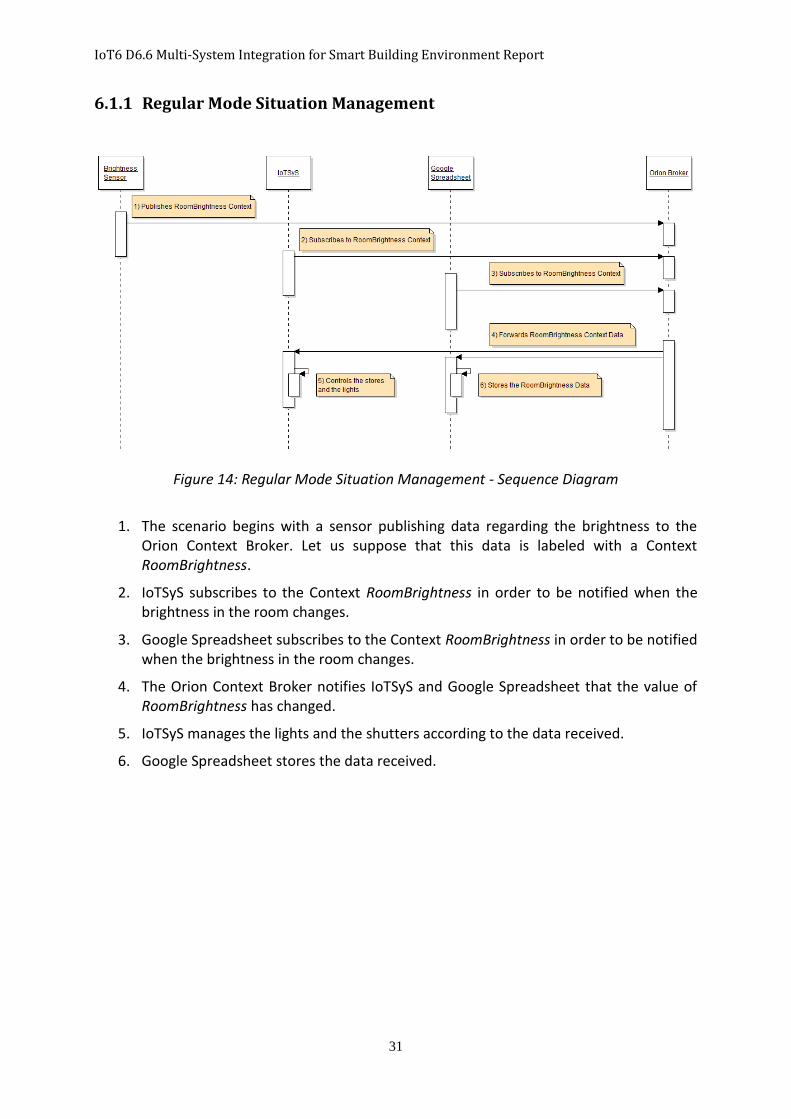
Figure 14: Regular Mode Situation Management - Sequence Diagram
1. The scenario begins with a sensor publishing data regarding the brightness to the
Orion Context Broker. Let us suppose that this data is labeled with a Context RoomBrightness.
2. IoTSyS subscribes to the Context RoomBrightness in order to be notified when the brightness in the room changes.
3. Google Spreadsheet subscribes to the Context RoomBrightness in order to be notified when the brightness in the room changes.
4. The Orion Context Broker notifies IoTSyS and Google Spreadsheet that the value of RoomBrightness has changed.
5. IoTSyS manages the lights and the shutters according to the data received.
6. Google Spreadsheet stores the data received.
IoT6 D6.6 Multi-System Integration for Smart Building Environment Report
32
6.1.2 Switch to Comfort Mode
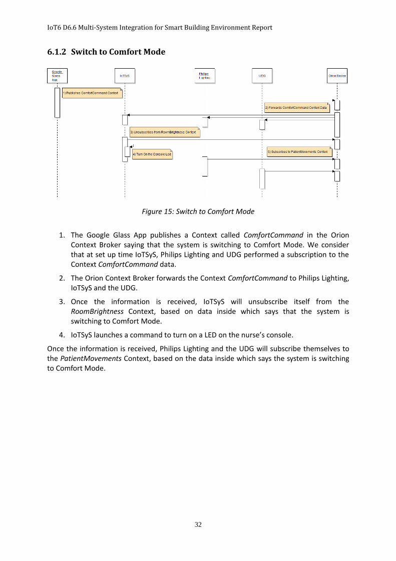
Figure 15: Switch to Comfort Mode
1. The Google Glass App publishes a Context called ComfortCommand in the Orion
Context Broker saying that the system is switching to Comfort Mode. We consider that at set up time IoTSyS, Philips Lighting and UDG performed a subscription to the Context ComfortCommand data.
2. The Orion Context Broker forwards the Context ComfortCommand to Philips Lighting, IoTSyS and the UDG.
3. Once the information is received, IoTSyS will unsubscribe itself from the RoomBrightness Context, based on data inside which says that the system is switching to Comfort Mode.
4. IoTSyS launches a command to turn on a LED on the nurse’s console.
Once the information is received, Philips Lighting and the UDG will subscribe themselves to the PatientMovements Context, based on the data inside which says the system is switching to Comfort Mode.
IoT6 D6.6 Multi-System Integration for Smart Building Environment Report
33
6.1.3 Comfort Mode Room Management
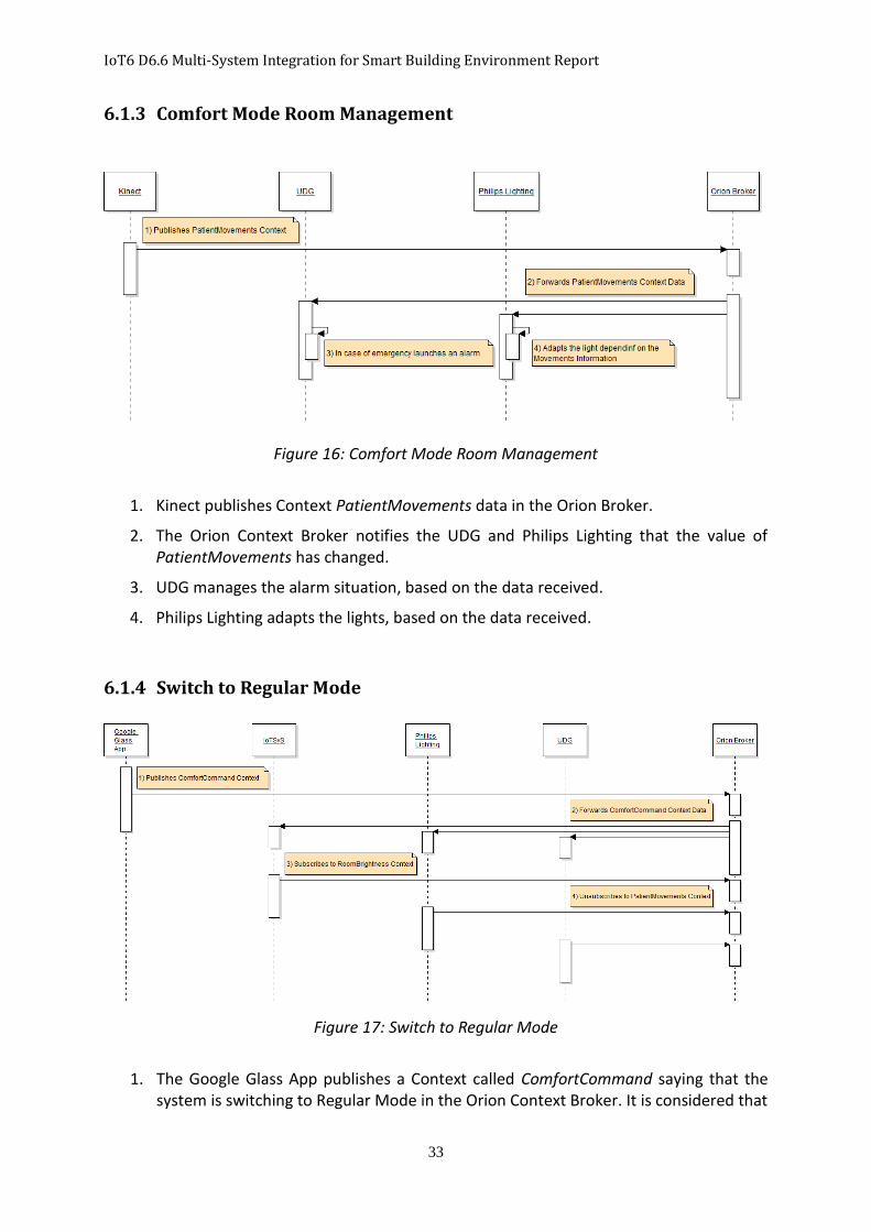
Figure 16: Comfort Mode Room Management
1. Kinect publishes Context PatientMovements data in the Orion Broker.
2. The Orion Context Broker notifies the UDG and Philips Lighting that the value of PatientMovements has changed.
3. UDG manages the alarm situation, based on the data received.
4. Philips Lighting adapts the lights, based on the data received.
6.1.4 Switch to Regular Mode
Figure 17: Switch to Regular Mode
1. The Google Glass App publishes a Context called ComfortCommand saying that the
system is switching to Regular Mode in the Orion Context Broker. It is considered that
IoT6 D6.6 Multi-System Integration for Smart Building Environment Report
34
at set up time IoTSyS, Philips Lighting and the UDG performed a subscription to the Context ComfortCommand data.
2. The Orion Context Broker forwards the Context ComfortCommand to Philips Lighting, IoTSyS and the UDG.
3. Once the information is received, IoTSyS will subscribe itself to the RoomBrightness Context, based on the data inside saying that the system is switching to Regular Mode.
4. Once the information is received, Philips Lighting and the UDG will unsubscribe themselves from the PatientMovements Context.
6.1.5 Query Information through Android App
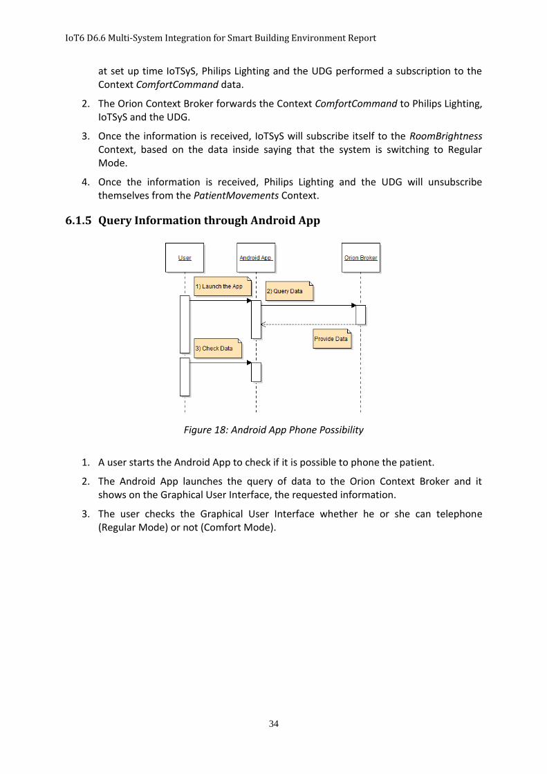
Figure 18: Android App Phone Possibility
1. A user starts the Android App to check if it is possible to phone the patient.
2. The Android App launches the query of data to the Orion Context Broker and it shows on the Graphical User Interface, the requested information.
3. The user checks the Graphical User Interface whether he or she can telephone (Regular Mode) or not (Comfort Mode).
IoT6 D6.6 Multi-System Integration for Smart Building Environment Report
35
7 Implementation & Deployment Details
This section details the implementation of the full system. The implementation is based on the above scenario and what each component will perform in our system. The decisions which each component will perform, together with the Entity Design, classify each component as a Publisher, Subscriber or Query Entity. Publisher and Query Entities works only as a Web Client of the system while a Subscriber Entity works as a Web Client to join the system and as a Web Service to receive subscription notifications.
The following technologies are used throughout the implementation: Java17 as the programming language, JSON as the data format and REST as the software architectural style for the web service.
7.1 Components’ Classification
This subsection shows the classification of the components. The components are classified as Publisher Entities or as Query Entities or as Subscriber Entities, according to their interaction within the system with the Orion Context Broker.
7.1.1 Publisher Entities
The components listed below will act only as a Web Client to interact with the Orion Context Broker, in order to be connected within the system and publish information about it.
XBee Brightness Sensor
Google Glass App
Microsoft Kinect
7.1.2 Query Entities
The component listed below will act only as a Web Client to interact with the Orion Context Broker, in order to be connected within the system and query context information about it.
Android App
7.1.3 Subscriber Entities
The components listed below will act as a Web Client to interact with the Orion Context Broker, in order to be connected within the system and publish information about it; moreover, they will act also as Web Service, to receive the notifications resulting from changes in information they are interested in.
IoTSyS
Google Spreadsheet
Philips Lighting
UDG
17 http://docs.oracle.com/javase/tutorial/
IoT6 D6.6 Multi-System Integration for Smart Building Environment Report
36
7.2 Components’ Implementation
The concrete implementation depends on what actions the components want to perform on the Orion Context Broker, and what they want to do with the information they obtain from it. This section shows how every component becomes an Entity, allowing it to be interfaced with the system in order to exchange information through the Orion Context Broker. The section illustrates also the data each component receives, and what they will perform later on in their own system (without going into their internal details). In order to establish a connection, all Entities will use a URL, which is the URL where the FI-LAB instance of the Orion Context Broker is deployed.
7.2.1 Publisher Entities
All components that intend to act as Publisher Entities have to perform the following two tasks: a) To create a Publisher Entity that will allow it to work as Web Client:
PublisherEntity publisherEntity = new PublisherEntity();
b) To connect itself to the Orion Context Broker, creating a WebResource as reference for
that connection:
WebResource webResource = publisherEntity.connectEntity(url);
In order to publish the information into the Orion Context Broker, the following three tasks must be performed:
a) To create the information they want to publish (each component will create its own
information):
PublicationData publishData = new PublicationData();
publishData.setElement("Hospital", "PatientRoom01");
publishData.setAttribute("ComfortCommand", "Comfort Set Up", "true");
publishData.setAction("APPEND");
b) To create the JSON object given the information just created:
JSONObject contextPayload = publishData.getData(); The JSON object will have the following representation:

IoT6 D6.6 Multi-System Integration for Smart Building Environment Report
37
When that JSON object is created, it means that we want to publish information about a context type Hospital with an id PatientRoom01, and the attribute the information is conveying has a name ComfortCommand, a value true and its type is Comfort Set Up.
c) To publish that information – its JSON representation – to the Orion Context Broker using
the WebResource:
publisherEntity.publish(webResource, "updateContext", contextPayload);
updateContext : means that we want to perform an NSGI10/updateContext Fi-Ware operation
7.2.1.1 XBee Brightness Sensor
The Publisher Entity that manages the brightness sensor captures the data sent by the sensor, and publishes it into the Orion Context Broker. The JSON format of that information is as follows:
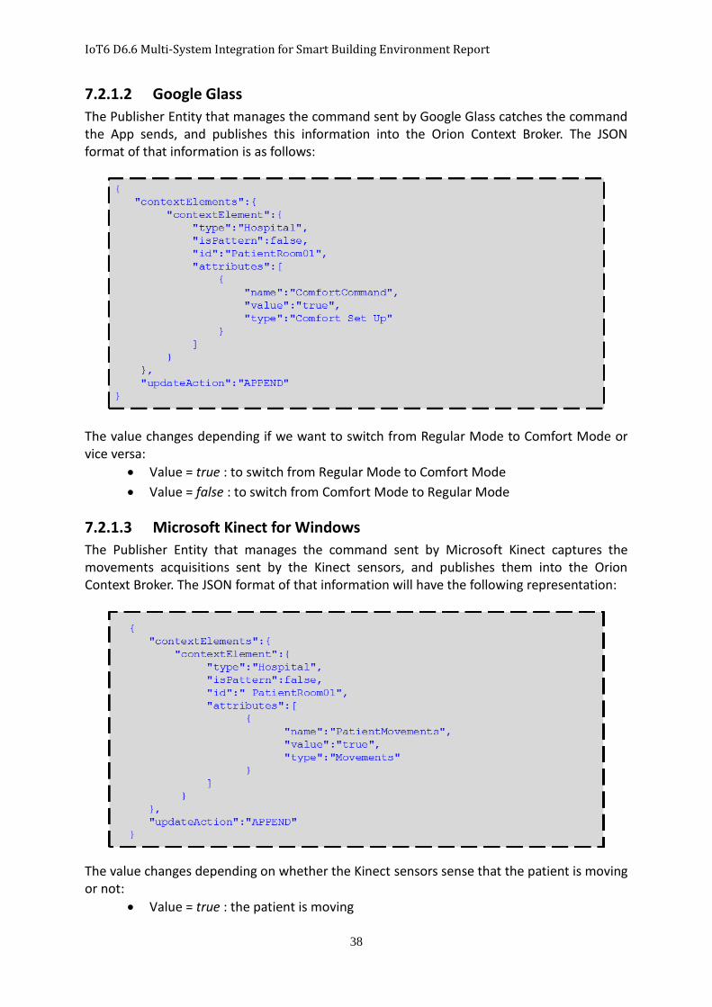
IoT6 D6.6 Multi-System Integration for Smart Building Environment Report
38
7.2.1.2 Google Glass
The Publisher Entity that manages the command sent by Google Glass catches the command the App sends, and publishes this information into the Orion Context Broker. The JSON format of that information is as follows:
The value changes depending if we want to switch from Regular Mode to Comfort Mode or vice versa:
Value = true : to switch from Regular Mode to Comfort Mode
Value = false : to switch from Comfort Mode to Regular Mode
7.2.1.3 Microsoft Kinect for Windows
The Publisher Entity that manages the command sent by Microsoft Kinect captures the movements acquisitions sent by the Kinect sensors, and publishes them into the Orion Context Broker. The JSON format of that information will have the following representation:
The value changes depending on whether the Kinect sensors sense that the patient is moving or not:
Value = true : the patient is moving
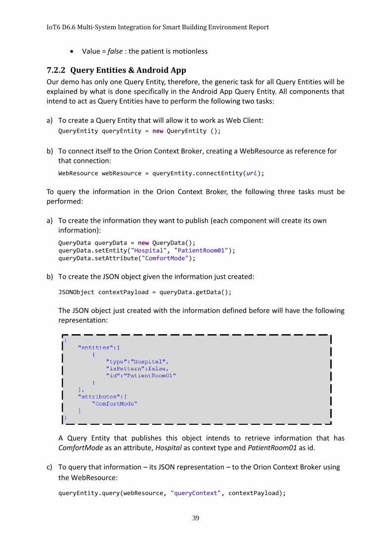
IoT6 D6.6 Multi-System Integration for Smart Building Environment Report
39
Value = false : the patient is motionless
7.2.2 Query Entities & Android App
Our demo has only one Query Entity, therefore, the generic task for all Query Entities will be explained by what is done specifically in the Android App Query Entity. All components that intend to act as Query Entities have to perform the following two tasks: a) To create a Query Entity that will allow it to work as Web Client:
QueryEntity queryEntity = new QueryEntity ();
b) To connect itself to the Orion Context Broker, creating a WebResource as reference for that connection:
WebResource webResource = queryEntity.connectEntity(url); To query the information in the Orion Context Broker, the following three tasks must be performed: a) To create the information they want to publish (each component will create its own
information):
QueryData queryData = new QueryData(); queryData.setEntity("Hospital", "PatientRoom01"); queryData.setAttribute("ComfortMode");
b) To create the JSON object given the information just created:
JSONObject contextPayload = queryData.getData();
The JSON object just created with the information defined before will have the following representation:
A Query Entity that publishes this object intends to retrieve information that has ComfortMode as an attribute, Hospital as context type and PatientRoom01 as id.
c) To query that information – its JSON representation – to the Orion Context Broker using
the WebResource:
queryEntity.query(webResource, "queryContext", contextPayload);

IoT6 D6.6 Multi-System Integration for Smart Building Environment Report
40
queryContext: means that we want to perform an NSGI10/queryContext FI-WARE operation.
7.2.3 Subscriber Entities
All components that intent to act as Subscriber Entities have to pass through two different
phases:
Web Client phase: To become a member of the system and to express its desire to
receive notifications on the Web Service that it has to implement.
Web Service phase: To create a RESTful web service that manages the notifications
and make the data carried inside the information available for the component.
Web Client Phase
All components that want to become Subscriber Entities have to perform the following two tasks:
a) To create a Subscriber Entity that will allow it to work as the Web Client:
SubscriberEntity subscriberEntity = new SubscriberEntity();
b) To connect itself to the Orion Context Broker, creating a WebResource as reference for
that connection:
WebResource webResource = subscriberEntity.connectEntity(url); In order to subscribe to information into the Orion Context Broker, the following three tasks have to be performed: a) To create the information they need in order to do the subscription (each component
will create its own information):
SubscriptionData subscribeData = new SubscriptionData ()
subscribeData.setAttribute("ComfortCommand");
subscribeData.setEntity("Hospital", "PatientRoom01");
subscribeData.setDuration(1);
subscribeData.setReference(yourWebServiceURL);
subscribeData.setNotifyCondition("ONCHANGE", "ComfortCommand");
To subscribe to the information, a Subscriber Entity has to specify the url where the Web Service that will manage the notifications is deployed. This is specified in the variable yourWebServiceURL.
b) To create the JSON object given the information just created:
JSONObject contextPayload = publishData.getData();
The JSON object will have the following representation:

IoT6 D6.6 Multi-System Integration for Smart Building Environment Report
41
A Subscriber Entity that publishes this object intends to retrieve information that has Hospital as the context type, PatientRoom01 as id, and ComfortCommand as condition for the notifications. The Web Service will be listening at the reference URL and it will receive notification when the value of the attribute changes – type is ONCHANGE (if the changes do not occur within 5 second intervals after the previous change - throttling is PT5S). The subscription will last one month – duration is P1M.
c) To subscribe to that information – its JSON representation – to the Orion Context Broker
using the WebResource:
subscriberEntity.subscribe(webResource, "subscribeContext", contextPayload);
subscribeContext: means that we want to perform an NSGI10/subscribeContext FI-WARE operation.
Web Service Phase
A Web Service skeleton that a user can use as the starting point for its own web services has been created. This skeleton provides the REST methods with the right Headers for the communication with the Orion Context Broker, abstracting the users from the issues they could encounter.
The skeleton is made in a way that a user can use his or her own code in this project. The user needs to just, replace the red part of the URL below with his or her Servlet18 URL.
http://ec2-54-247-170-110.eu-west-1.compute.amazonaws.com/rest/notificationManager/
The access point of the code should be in the web path highlighted in blue. In case, the user has already his or her own web service and wants to add another web resource, the user can
18 http://en.wikipedia.org/wiki/Java_Servlet
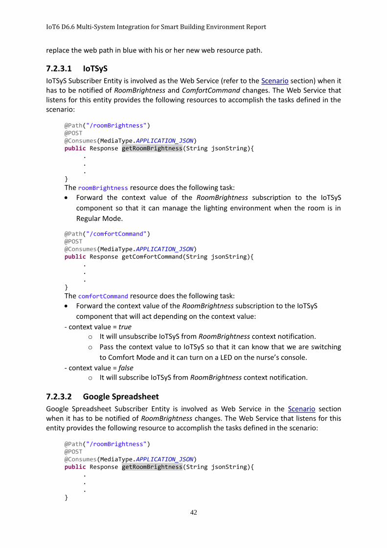
IoT6 D6.6 Multi-System Integration for Smart Building Environment Report
42
replace the web path in blue with his or her new web resource path.
7.2.3.1 IoTSyS
IoTSyS Subscriber Entity is involved as the Web Service (refer to the Scenario section) when it has to be notified of RoomBrightness and ComfortCommand changes. The Web Service that listens for this entity provides the following resources to accomplish the tasks defined in the scenario:
@Path("/roomBrightness")
@POST @Consumes(MediaType.APPLICATION_JSON) public Response getRoomBrightness(String jsonString){ .
. .
}
The roomBrightness resource does the following task:
Forward the context value of the RoomBrightness subscription to the IoTSyS
component so that it can manage the lighting environment when the room is in
Regular Mode.
@Path("/comfortCommand") @POST @Consumes(MediaType.APPLICATION_JSON) public Response getComfortCommand(String jsonString){
.
. .
}
The comfortCommand resource does the following task:
Forward the context value of the RoomBrightness subscription to the IoTSyS
component that will act depending on the context value:
- context value = true o It will unsubscribe IoTSyS from RoomBrightness context notification.
o Pass the context value to IoTSyS so that it can know that we are switching
to Comfort Mode and it can turn on a LED on the nurse’s console.
- context value = false o It will subscribe IoTSyS from RoomBrightness context notification.
7.2.3.2 Google Spreadsheet
Google Spreadsheet Subscriber Entity is involved as Web Service in the Scenario section when it has to be notified of RoomBrightness changes. The Web Service that listens for this entity provides the following resource to accomplish the tasks defined in the scenario:
@Path("/roomBrightness")
@POST @Consumes(MediaType.APPLICATION_JSON) public Response getRoomBrightness(String jsonString){ .
. .
}
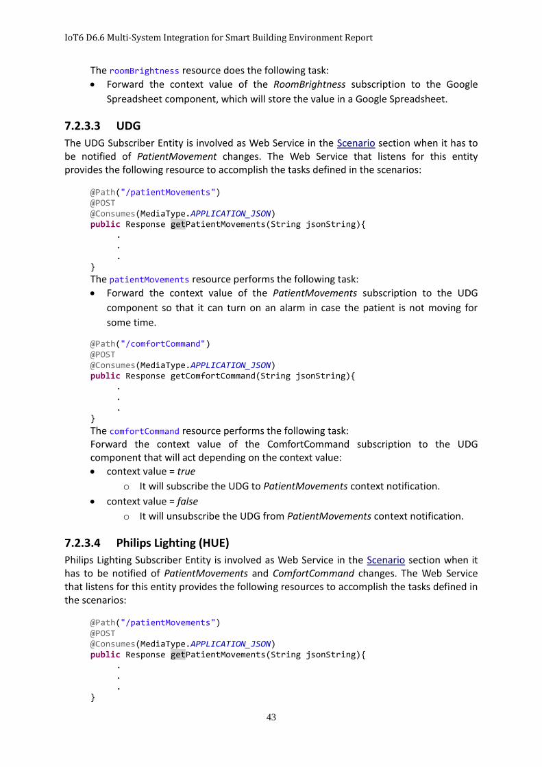
IoT6 D6.6 Multi-System Integration for Smart Building Environment Report
43
The roomBrightness resource does the following task:
Forward the context value of the RoomBrightness subscription to the Google
Spreadsheet component, which will store the value in a Google Spreadsheet.
7.2.3.3 UDG
The UDG Subscriber Entity is involved as Web Service in the Scenario section when it has to be notified of PatientMovement changes. The Web Service that listens for this entity provides the following resource to accomplish the tasks defined in the scenarios:
@Path("/patientMovements")
@POST @Consumes(MediaType.APPLICATION_JSON) public Response getPatientMovements(String jsonString){ .
. .
}
The patientMovements resource performs the following task:
Forward the context value of the PatientMovements subscription to the UDG
component so that it can turn on an alarm in case the patient is not moving for
some time.
@Path("/comfortCommand") @POST @Consumes(MediaType.APPLICATION_JSON) public Response getComfortCommand(String jsonString){
.
. .
}
The comfortCommand resource performs the following task: Forward the context value of the ComfortCommand subscription to the UDG component that will act depending on the context value:
context value = true
o It will subscribe the UDG to PatientMovements context notification.
context value = false
o It will unsubscribe the UDG from PatientMovements context notification.
7.2.3.4 Philips Lighting (HUE)
Philips Lighting Subscriber Entity is involved as Web Service in the Scenario section when it has to be notified of PatientMovements and ComfortCommand changes. The Web Service that listens for this entity provides the following resources to accomplish the tasks defined in the scenarios:
@Path("/patientMovements")
@POST @Consumes(MediaType.APPLICATION_JSON) public Response getPatientMovements(String jsonString){ .
. .
}
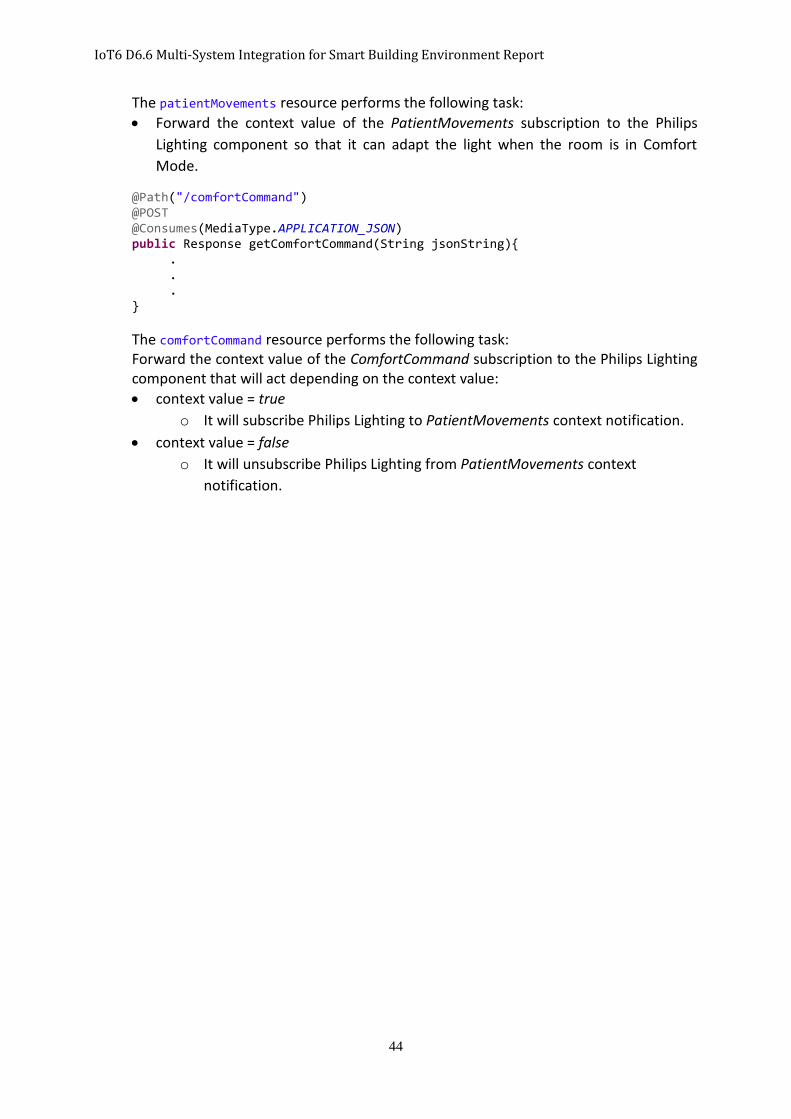
IoT6 D6.6 Multi-System Integration for Smart Building Environment Report
44
The patientMovements resource performs the following task:
Forward the context value of the PatientMovements subscription to the Philips
Lighting component so that it can adapt the light when the room is in Comfort
Mode.
@Path("/comfortCommand") @POST @Consumes(MediaType.APPLICATION_JSON) public Response getComfortCommand(String jsonString){
.
. .
}
The comfortCommand resource performs the following task: Forward the context value of the ComfortCommand subscription to the Philips Lighting component that will act depending on the context value:
context value = true
o It will subscribe Philips Lighting to PatientMovements context notification.
context value = false
o It will unsubscribe Philips Lighting from PatientMovements context
notification.
IoT6 D6.6 Multi-System Integration for Smart Building Environment Report
45
8 Conclusion and Outlook
This deliverable documents the work of the IoT6 ecosystem integration with smart building systems, performed in the context of WP6 “Mobile network, STIS & business processes interactions”, and according to the Task T6.5 “Enabling multi-systems integration for smart building environment”. We created an implementation of the Publish/Subscribe paradigm, named Orion Context Broker which was chosen as the integration model for our system. This integration model facilitates the set-up of communications by connecting components in an N-N way, and considers only the information they are interested in, rather than setting-up all connections in a 1-1 way. In this way, the integration model does not have to consider the components involved.
This deliverable describes the software engineering phases which created the interfaces that allow all components employed to use that integration model, and how those interfaces are connected to the Orion Context Broker.
Moreover, this deliverable documents a scenario used to test the integration required in Task T6.5. The tests performed on the system based on the scenario, demonstrated that the integration was fully successful, and that this system can be an excellent contribution to the Internet of Things integration domain.
This system will simplify the connection of the components that will take part in the demonstration phase based on Task T7.3 “Demonstrating new business processes combining the various IoT6 components”.

IoT6 D6.6 Multi-System Integration for Smart Building Environment Report
46
9 References
[1] “Communication Paradigms for Distributed Network Systems,” in Distributed Network Systems, vol. 15, Springer US, 2005, pp. 33-64.
[2] P. T. a. F. P. A. a. G. R. a. K. A.-M. Eugster, “The many faces of publish/subscribe.,” ACM Comput. Surv., vol. 35, no. 2, pp. 114 -- 131, June 2003.
[3] “oBIX Version 1.1 Working Draft 06,” 08 06 2010. [Online]. Available: https://www.oasis-open.org/committees/download.php/38212/oBIX-1-1-spec-wd06.pdf.
[4] I. Jacobson, M. Christerson, P. Jonsson and G. G. Overgaard, Object-Oriented Software Engineering: A Use-Case Driven Approach, The Association for Computing Machinery, 1992.
[5] O. M. A. Ltd, “http://technical.openmobilealliance.org/,” 29 May 2012. [Online]. Available: http://technical.openmobilealliance.org/Technical/release_program/docs/NGSI/V1_0-20120529-A/OMA-TS-NGSI_Context_Management-V1_0-20120529-A.pdf.

IoT6 D6.6 Multi-System Integration for Smart Building Environment Report
47
10 List of Figures
Figure 1: Primary Use Cases .................................................................................................................... 7
Figure 2: Domain Model (Requirements’ Analysis version) .................................................................. 10
Figure 3: IoT6 Ecosystem ....................................................................................................................... 13
Figure 4: Logical Architecture (High Level View) ................................................................................... 17
Figure 5: Entity - ConnectionManager .................................................................................................. 19
Figure 6: Entity – MessageManager ...................................................................................................... 20
Figure 7: MessageManager – Translator ............................................................................................... 20
Figure 8: Building Logic workflow.......................................................................................................... 21
Figure 9: Logical Architecture including Orion Broker .......................................................................... 25
Figure 10: Model of Boundary Package ................................................................................................ 26
Figure 11: Model of Control Package .................................................................................................... 28
Figure 12: Model of Entity Package ....................................................................................................... 29
Figure 13: Model of the Final Logical Architecture ............................................................................... 29
Figure 14: Regular Mode Situation Management - Sequence Diagram ................................................ 31
Figure 15: Switch to Comfort Mode ...................................................................................................... 32
Figure 16: Comfort Mode Room Management ..................................................................................... 33
Figure 17: Switch to Regular Mode ....................................................................................................... 33
Figure 18: Android App Phone Possibility ............................................................................................. 34
11 List of Tables
Table 1: Glossary ..................................................................................................................................... 7
Table 2: Exchange Data Use Case ............................................................................................................ 8
Table 3: Set Up Connection Use Case...................................................................................................... 8
Table 4: Translate IoT6 Message Use Case ............................................................................................. 8
Table 5: Translate Building Message Use Case ....................................................................................... 9
Table 6: Integrate IoT6 Entity Use Case .................................................................................................. 9
Table 7: Integrate Building Entity Use Case ............................................................................................ 9
Table 9: Standard NGSI-9 Operation Resources .................................................................................... 23
Table 10: Standard NGSI-10 Operation Resources ................................................................................ 24