Embed Size (px)
Citation preview


UNIVERSITY OF HONG KONGLIBRARY
Hong Kong Collection
CODE OF PRACTICE
ON WIND EFFECTS
HONG KONG-1983
BUILDING DEVELOPMENT DEPARTMENT
HONG KONG
PRINTED AND PUBLISHED BY THE GOVERNMENT PRINTER, HONG KONG
FOREWORD
This Code of Practice on Wind Effects prepared under the direction of the Working Party on the Review of theBuilding (Construction) Regulations, revises and supersedes the 1976 edition.
An important change in this edition from the 1976 edition is the adoption of gust velocity as the basis for designand the re-assessment of the probable wind speeds on a statistical basis in accordance with records from the HongKong Royal Observatory.
This edition treats wind loading in more detail and takes account of the local variation in the ground surface in asimilar manner to that used in BS CP 3: Chapter V: Part 2: 1972.
This edition also uses wind data that has become available since 1976 and it is intended that when further databecomes available the code will be reviewed and updated.
A draft of the code was circulated for general comment to selected practising engineers and GovernmentDepartments. All comments and views expressed have been taken into consideration in the preparation of thecode now published.

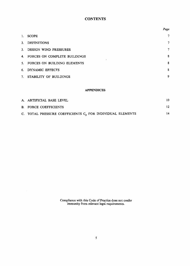
CONTENTS
Page
1. SCOPE 7
2. DEFINITIONS 7
3. DESIGN WIND PRESSURES 7
4. FORCES ON COMPLETE BUILDINGS 8
5. FORCES ON BUILDING ELEMENTS 8
6. DYNAMIC EFFECTS 8
7. STABILITY OF BUILDINGS 9
APPENDICES
A. ARTIFICIAL BASE LEVEL 10
B. FORCE COEFFICIENTS 12
C. TOTAL PRESSURE COEFFICIENTS Cp FOR INDIVIDUAL ELEMENTS 14
Compliance with this Code of Practice does not conferimmunity from relevant legal requirements.

1. SCOPE
1.1 This Code of Practice gives general methods for calculating the wind loads to be used in the structural designof buildings or parts of buildings. The Code does not apply to buildings of an unusual shape or buildingssituated at locations where the local topography significantly affects the wind conditions. Experimental windtunnel data with reference to local conditions, where available, may be used in place of the coefficients givenin this Code.
1.2 The design wind pressures given in this Code have been determined from the peak gust velocities having amean return period of 50 years and are the normal wind loads on completed buildings. Design wind pressureson buildings where a longer period of exposure to the wind is required or buildings where greater than normalsafety is required shall be determined from peak gust velocities having a mean return period greater than 50years.
2. DEFINITIONS
For the purposes of this Code, the following definitions apply:
"Breadth" means the horizontal dimension normal to the direction of the wind."Depth" means the horizontal dimension parallel to the direction of the wind."Frontal projected area" means the area of the shadow projection on a plane normal to the direction of the wind."Height of building" means the height of the building above the site-ground level in the immediate vicinity of the
building.
3. DESIGN WIND PRESSURES
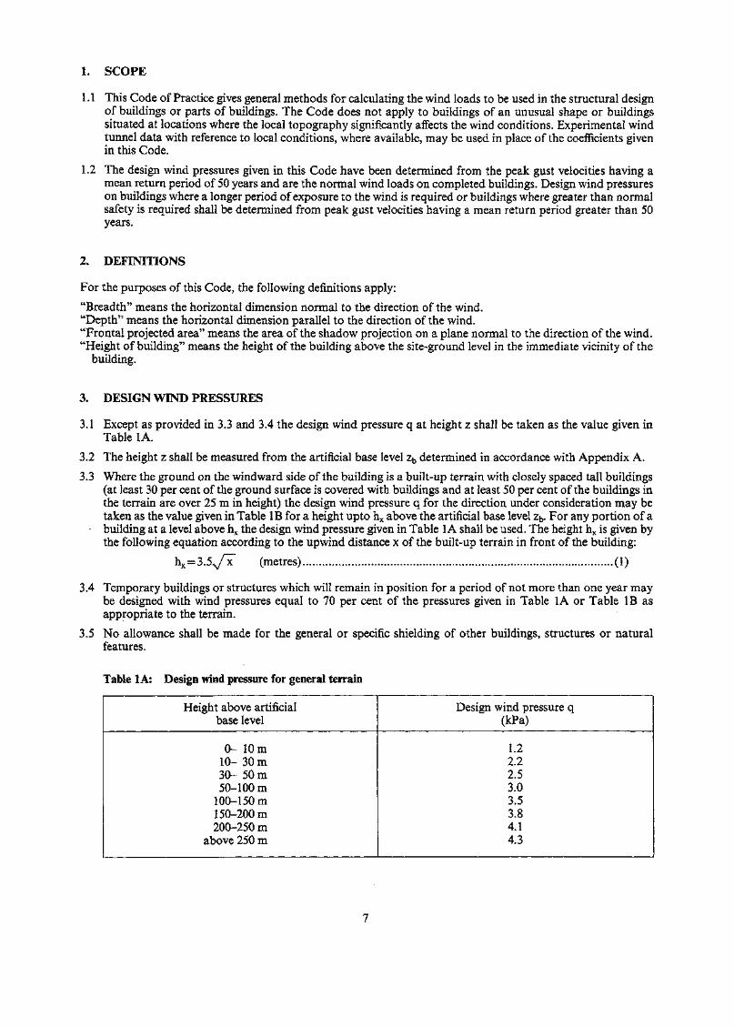
3.1 Except as provided in 3.3 and 3.4 the design wind pressure q at height z shall be taken as the value given inTable 1A.
3.2 The height z shall be measured from the artificial base level zb determined in accordance with Appendix A.
3.3 Where the ground on the windward side of the building is a built-up terrain with closely spaced tall buildings(at least 30 per cent of the ground surface is covered with buildings and at least 50 per cent of the buildings inthe terrain are over 25 m in height) the design wind pressure q for the direction under consideration may betaken as the value given in Table IB for a height upto hx above the artificial base level zb. For any portion of abuilding at a level above hx the design wind pressure given in Table 1A shall be used. The height hx is given bythe following equation according to the upwind distance x of the built-up terrain in front of the building:
hx = 3.5.v/x (metres) (1)
3.4 Temporary buildings or structures which will remain in position for a period of not more than one year maybe designed with wind pressures equal to 70 per cent of the pressures given in Table 1A or Table IB asappropriate to the terrain.
3.5 No allowance shall be made for the general or specific shielding of other buildings, structures or naturalfeatures.
Table 1 A: Design wind pressure for general terrain
Height above artificialbase level
0- 10m10- 30m30- 50 m50-100 m
100-1 50m1 50-200 m200-250 m
above 250m
Design wind pressure q(kPa)
1.22.22.53.03.53.84.143
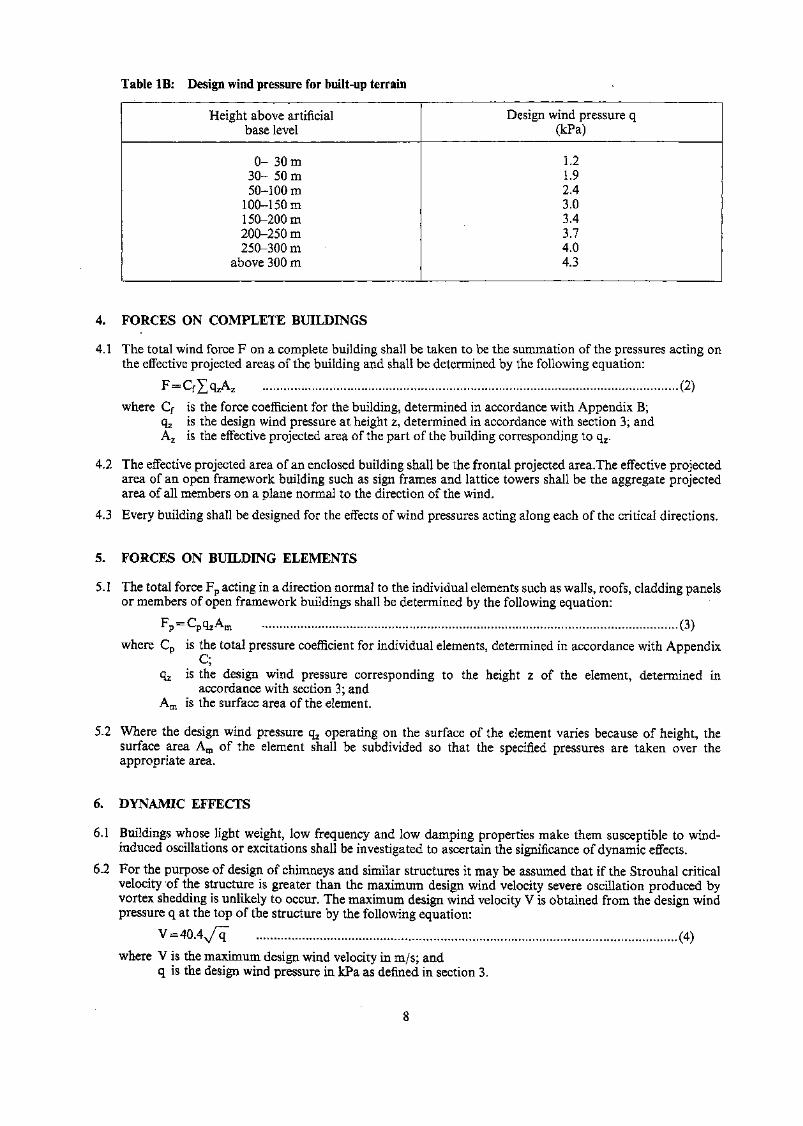
Table IB: Design wind pressure for built-up terrain
Height above artificialbase level
0- 30m30- 50 m50-1 00m
100-1 50m1 50-200 m200-250 m250-300 m
above 300 m
Design wind pressure q(kPa)
1.21.92.43.03.43.74.04.3
4. FORCES ON COMPLETE BUILDINGS
4.1 The total wind force F on a complete building shall be taken to be the summation of the pressures acting onthe effective projected areas of the building and shall be determined by the following equation:
(2)
where Cf is the force coefficient for the building, determined in accordance with Appendix B;qz is the design wind pressure at height z, determined in accordance with section 3; andAz is the effective projected area of the part of the building corresponding to qz.
4.2 The effective projected area of an enclosed building shall be the frontal projected area.The effective projectedarea of an open framework building such as sign frames and lattice towers shall be the aggregate projectedarea of all members on a plane normal to the direction of the wind.
4.3 Every building shall be designed for the effects of wind pressures acting along each of the critical directions.
5. FORCES ON BUILDING ELEMENTS
5.1 The total force Fp acting in a direction normal to the individual elements such as walls, roofs, cladding panelsor members of open framework buildings shall be determined by the following equation:
Fp = CpqzAm (3)
where Cp is the total pressure coefficient for individual elements, determined in accordance with AppendixQ
qz is the design wind pressure corresponding to the height z of the element, determined inaccordance with section 3; and
Am is the surface area of the element.
5.2 Where the design wind pressure qz operating on the surface of the element varies because of height, thesurface area Am of the element shall be subdivided so that the specified pressures are taken over theappropriate area.
6. DYNAMIC EFFECTS
6.1 Buildings whose light weight, low frequency and low damping properties make them susceptible to wind-induced oscillations or excitations shall be investigated to ascertain the significance of dynamic effects.
6.2 For the purpose of design of chimneys and similar structures it may be assumed that if the Strouhal criticalvelocity of the structure is greater than the maximum design wind velocity severe oscillation produced byvortex shedding is unlikely to occur. The maximum design wind velocity V is obtained from the design windpressure q at the top of the structure by the following equation:
V=40A
where V is the maximum design wind velocity in m/s; andq is the design wind pressure in kPa as defined in section 3.

7. STABILITY OF BUILDINGS
The stability of the building or part of a building shall be investigated and the resistance to sliding, uplift andoverturning shall be not less than 1.5 times the maximum sliding force, uplift force and over-turning moment dueto the design wind load.
APPENDIX A: ARTIFICIAL BASE LEVEL
Al. In the case where within an upwind distance of 400 m in front of the building the variation of ground level isnot more than 3 m in any 10 m horizontal distance, and in the case where the wind stream is downhilltowards the building, the artificial base level zb shall be taken as the average ground level adjacent to thewindward face of the building.
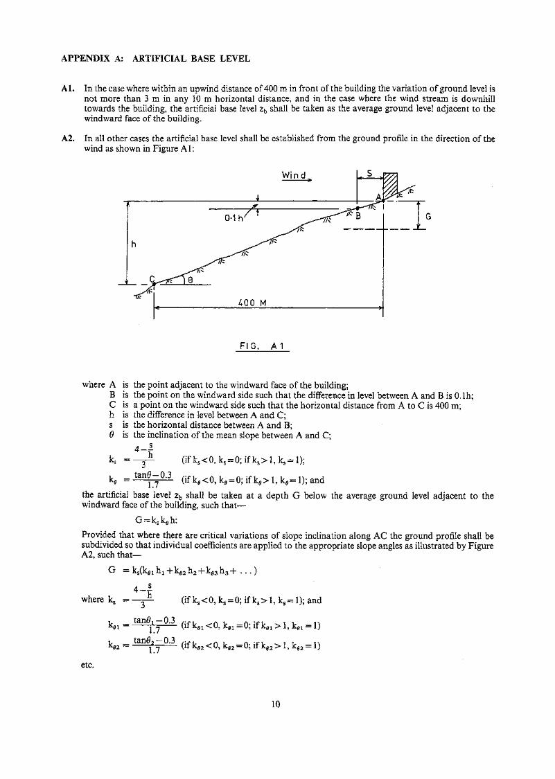
A2. In all other cases the artificial base level shall be established from the ground profile in the direction of thewind as shown in Figure Al:
Wind
FIG. A 1
where A is the point adjacent to the windward face of the building;B is the point on the windward side such that the difference in level between A and B is O.lh;C is a point on the windward side such that the horizontal distance from A to C is 400 m;h is the difference in level between A and C;s is the horizontal distance between A and B;9 is the inclination of the mean slope between A and C;
(ifk s<0,k s = 0 ; i fk s >l ,k s =l) ;
k = tang-- 0.3
the artificial base level zb shall be taken at a. depth G below the average ground level adjacent to thewindward face of the building, such that —
Provided that where there are critical variations of slope inclination along AC the ground profile shall besubdivided so that individual coefficients are applied to the appropriate slope angles as illustrated by FigureA2, such that —
G =
.4-4where ks = (if ks<0, ks = 0; if ks> I, ks= 1); and
v —K.02 — tart0,-0.3 ,..f-f^ ( ifk f l 2<0,kM = 0; i fk,3>l,kM = l)
etc.
10
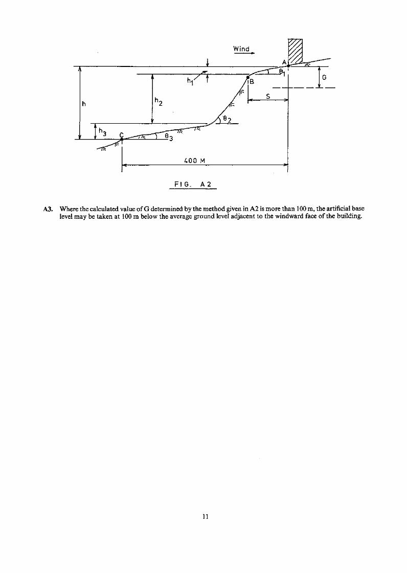
FIG. A 2
A3. Where the calculated value of G determined by the method given in A2 is more than 100 m, the artificial baselevel may be taken at 100 m below the average ground level adjacent to the windward face of the building.
11
APPENDIX B: COEFFICIENTS
Bl. Enclosed buildingsB1.1 The force coefficient Cf for an enclosed building shall be—
(a) the product of the height aspect factor Ch and the shape factor Cs given in Table B1 and Table B2respectively; or
(b) the appropriate value specified in BS CP3: Chapter V: Part 2.
B1.2 The force coefficient shall be applied to the building as a whole:Provided that in the case of a building with isolated blocks projecting above a general roof levelindividual force coefficients corresponding to the height and shape of each block shall be applied.
Bl .3 If the frontal projected area of that part of the building for which Cf operates is greater than 500 m2
the force coefficient determined by B 1.1 may be multiplied by a reduction factor RA given in Table B3.
B2. Open framework buildingsB2.1 The force coefficient Cf for an open framework building shall be—
(a) the value given in Table B4; or(b) appropriate value specified in BS CP3: Chapter V: Part 2
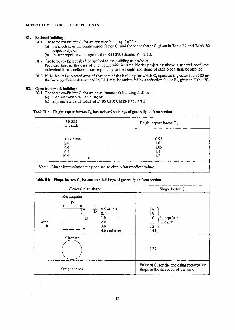
Table Bl: Height aspect factors Ch for enclosed buildings of generally uniform section
HeightBreadth
1.0 or less2.04.06.0
10.0
Height aspect factor Ch
0.951.01.051.11.2
Note: Linear interpolation may be used to obtain intermediate values.
Table B2: Shape factors Cs for enclosed buildings of generally uniform section
General plan shape
Rectangular
DB /\ /- i-=r- = 0.5 or lessU 0.7
B 1-0wind 2.0— » 3.0
4.0 and over
Circular
OOther shapes
Shape factor Cs
0.8 ~]0.91.0 [interpolate1.1 [ linearly1.31.45 J
0.75
Value of Cs for the enclosing rectangularshape in the direction of the wind.
12
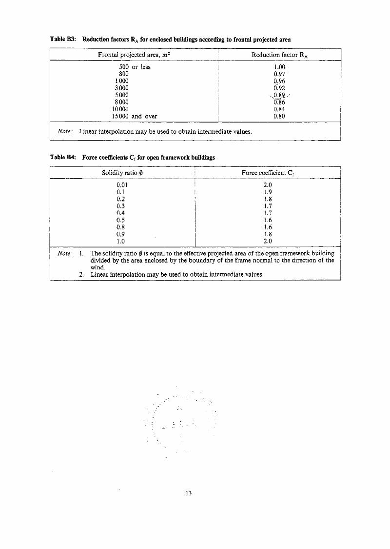
Table B3: Reduction factors RA for enclosed buildings according to frontal projected area
Frontal projected area, m2 Reduction factor RA
500 or less LOO800 0.97
1 000 0.963000 0.9250008000
1000015000 and over
xO.sa >6.860.840.80
Note: Linear interpolation may be used to obtain intermediate values.
Table B4: Force coefficients Cf for open framework buildings
Solidity ratio 0 Force coefficient Cf
0.010.1
2.01.9
0.2 ! 1.80.3 | 1.70.40.50.80.91.0
1.71.61.61.82.0
Note: I . The solidity ratio 0 is equal to the effective projected area of the open framework buildingdivided by the area enclosed by the boundary of the frame normal to the direction of thewind.
2. Linear interpolation may be used to obtain intermediate values.
13
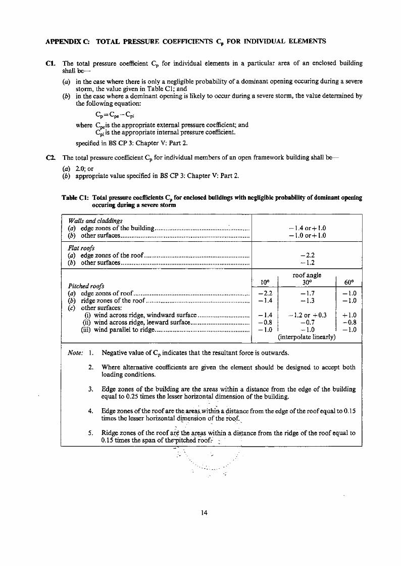
APPENDIX C: TOTAL PRESSURE COEFFICIENTS Cp FOR INDIVIDUAL ELEMENTS
Cl. The total pressure coefficient Cp for individual elements in a particular area of an enclosed buildingshall be—
(a) in the case where there is only a negligible probability of a dominant opening occuring during a severestorm, the value given in Table Cl; and
(b) in the case where a dominant opening is likely to occur during a severe storm, the value determined bythe following equation:
L<p = Cpe L/pj
where Cpeis the appropriate external pressure coefficient; andCpi is the appropriate internal pressure coefficient.
specified in BS CP 3: Chapter V: Part 2.
C2. The total pressure coefficient Cp for individual members of an open framework building shall be—
(a) 2.0; or(b) appropriate value specified in BS CP 3: Chapter V: Part 2.
Table Cl: Total pressure coefficients Cp for enclosed buildings with negligible probability of dominant openingoccuring during a severe storm
Walls and claddings(a) edge zones of the building.(b) other surfaces
-1.4or+1.0-1.0 or +1.0
Flat roofs(a) edge zones of the roof.(b) other surfaces
-2.2—. \ 2
Pitched roofs(a) edge zones of roof(b) ridge zones of the roof(c) other surfaces:
(i) wind across ridge, windward surface.(ii) wind across ridge, leeward surface
(iii) wind parallel to ridge
10°
-2.2-1.4
-1.4-0.8-1.0
roof angle30°
-1.7-1.3
-1.2 or +0.3-0.7-1.0
(interpolate linearly)
60°
-1.0-1.0
+ 1.0-0.8-1.0
Note: 1. Negative value of Cp indicates that the resultant force is outwards.
2. Where alternative coefficients are given the element should be designed to accept bothloading conditions.
3. Edge zones of the building are the areas within a distance from the edge of the buildingequal to 0.25 times the lesser horizontal dimension of the building.
4. Edge zones of the roof are the areas within a distance from the edge of the roof equal to 0.15times the lesser horizontal dimension of the roof.
5. Ridge zones of the roof are the areas within a distance from the ridge of the roof equal to0.15 times the span of thepitched roofr
14

F13fit22017
HKP 352-12 H7 Bl
[HKP] 352.92 H7 B1
MBflbEEDl?
HKP 352.12 H7 Bl
i u ^ 13flt22DI H K . B u i l d i n g Development
Dept.
Date Due 1386220
NOT F03