Embed Size (px)
Citation preview
UNIVERSITY OF HONG KONGLIBRARY
Hong Kong CollectionGift from
H,K. Information Services Dept.
CODE OF PRACTICE
FOR THE
DESIGN CONSTRUCTION AND MAINTENANCE OF
OIL AND PETROLEUM FEEDSTOCK
INSTALLATIONS
BUILDING (OIL STORAGE INSTALLATIONS)
REGULATIONS
BUILDING DEVELOPMENT DEPARTMENT
HONGKONG
_JrJ^i£L*J?.£
PRINTED AND PUBLISHED BY THE GOVERNMENT PRINTER, HONG KONG
CONTENTS
SECTION A GENERAL
A.I SCOPE
A.2 DEFINITIONS AND CHARACTERISTICSA.2.1 DefinitionsA.3 HAZARDS
SECTION B DESIGN AND CONSTRUCTION
B.I SCOPEB.2 SITE INVESTIGATIONB.2.1 GeneralB.2.2 Type and Extent of Soil ExplorationB.2.3 Information and Soil Properties requiredB.3 FOUNDATIONSB.3.1 GeneralB.3.2 Compacted Granular FoundationsB.3.3 Concrete Ring Wall FoundationsB.3.4 Concrete Raft FoundationsB.3.5 Piled FoundationsB.3.6 Vibro-Compacted FoundationsB.3.7 SettlementB.4 BUNDED AREASB.4.1 GeneralB.4.2 Volume enclosed by Bund WallsB.4.3 Bund Wall ConstructionB.4.3.1 Earth or Rock Bunds ConstructionB.4.3.2 Gravity WallsB.4.3.3 Reinforced Concrete, Prestressed Concrete and Reinforced Masonry WallsB.4.4 Bund Floor ConstructionB.4.4.1 GeneralB.4.4.2 MaterialsB.4.4.3 Permeability of Bund Floor ConstructionB.4.4.4 Testing the Permeability of the Bund Floor ConstructionB.5 TANK DESIGNB.5.1 GeneralB.5.2 Wind LoadingB.5.3 Tank Bearing PadsB.5.4 Corrosion ProtectionB.6 DRAINAGEB.6.1 GeneralB.6.2 Drainage of Bunded AreasB.6.3 Tank Roof DrainageB.6.4 Valves and PenstocksB.6.5 Interceptors and SeparatorsB.6.6 Unbunded AreasB.6.6.2 Pipelines
Page1
1
1
1
7
99
101010101111111111111112121212131313151516161616161616161818181818

Page
SECTION C ASSOCIATED EQUIPMENT 19
C.I FENCING 19C.2 TANK FITTINGS AND CONNECTIONS 19
C.3 VALVES 19
C.4 VENTING REQUIREMENTS 19C,5 ELECTRICAL 19
SECTION D OPERATION AND MAINTENANCE 22
D.I OPERATION 22D.2 MAINTENANCE OF TANKS 23
APPENDIX 1 LABORATORY TESTING FOR THE PERMEABILITY OF BUND FLOORCONSTRUCTION 25
General 25
Method of Testing 25
The Test Specimen 25
APPENDIX 2 IN SITU TESTING FOR THE PERMEABILITY OF BUND FLOORCONSTRUCTION 26
General 26
Piezometer Testing 26
The Tube Test 26Field Trials 27
Any reference in this Code of Practice to a publication shall be construed as follows:—
a. in clauses where no date is included in the reference, the reference is to the edition thereof current at 31October 1981 together with any amendments, supplements or addenda thereto published at that date;
b. in any case where a date is included in the reference, the reference is to the edition of that date, together withany amendments, supplements and addenda thereto published at 31 October 1981; and
c. any reference to any publication is a reference to so much only thereof as is relevant in the context in whichsuch publication is quoted.
British Standards
B.S. 799 Oil Burning EquipmentB.S. 1377 Methods of Testing Soils for Civil Engineering purposesB.S. 2594 Horizontal Mild Steel Welded Storage TanksB.S. 2654 Vertical Steel Welded Storage Tanks with Butt-Welded Shells for the Petroleum Industry
British Standard Codes of Practice
B.S. 5628 Code of practice for the structural use of masonryC.P. 115 The structural use of prestressed concrete in buildingsC.P. 116 The structural use of precast concreteB.S. 5930 Site investigationsB.S. 6031 EarthworksC.P. 2004 FoundationsB.S. 5337 The structural use of concrete for retaining aqueous liquids
Other Codes of Practice (Currently under review)
C.E.C.P. 2 Earth retaining structures
Reference is also made in this Code of Practice to the following Codes, Standards and Publications:—
I.P. Standard for Petroleum and its ProductsI.P. Electrical Safety CodeI.P. Marketing Safety CodeInternational Oil Tanker and Terminal Safety Guide(Published by the Institute of Petroleum, London)European Model Code of Safe Practice in the Storage and Handling of Petroleum Products (Part II)A.P.L Standard 650: 3rd Edition: Welded Steel Tanks for Oil Storage(Published by the American Petroleum Institute)"Report of the Geological Survey on Hong Kong"(by P. M. Allen and E. A. Stephens)(Published by the Crown Lands and Survey Office, Hong Kong)Dangerous Goods Ordinance: Chapter 295 and Subsidiary Legislation(Published by the Government Printer, Hong Kong)
Notes:
The recommendations in this Hong Kong Code of Practice take account of local conditions. An oilspill itiHong Kong could be exceptionally damaging because of the territory's intensive use of its coastal land andrestricted waters.This Code of Practice represents a standard of good practice and therefore takes the form ofrecommendations. Compliance with it does not confer immunity from relevant legal requirements.Dangerous Goods licences granted pursuant to the provisions of Dangerous Goods Ordinance, Chapter 295are subject to licensing conditions imposed by the Director of Fire Services from time to time.

CODE OF PRACTICE FOR THEDESIGN, CONSTRUCTION AND MAINTENANCE OF OIL AND
PETROLEUM FEEDSTOCK INSTALLATIONS INHONG KONG
SECTION A GENERAL
A.I SCOPE
This Code of Practice deals with the design, construction and maintenance of oil and petroleumfeedstock installations in Hong Kong. For the purposes of this Code of Practice oil storageinstallations are storage tanks in bunded areas with associated structures as defined in theBuilding (Oil Storage Installations) Regulations, a group of tanks for licensing control purposescomprising those above ground within a required bunded areas, or series of such areas withshared facilities operated as one installation.
A. 1.1 The design and supervision of the building works related to installations covered by this Code ofPractice must be carried out under the direction of a Registered Structural Engineer and whererequired, all plans in respect thereof must be submitted to the Building Authority by anAuthorized Person. The operation and maintenance of such installations should be placed underthe charge of a competent person.
A. 1.2 The primary objective of the recommendations in this Code is to reduce the risks ofenvironmental pollution associated with the storage of oil and petroleum products to acceptablelevels. Reducing fire and explosion hazards will continue to be the responsibility of the Directorof Fire Services under the Dangerous Goods Ordinance, although some degree of overlap withthis Code of Practice is inevitable.
A.2 DEFINITIONS AND CHARACTERISTICS
A.2.1 Definitions
A.2.1.1 This Code of Practice covers storage facilities for petroleum products in liquid or solid state.Such petroleum products may consist of crude petroleum (petroleum feedstock) or semi-refinedor wholly refined petroleum.
A.2.1.2 It is customary to divide petroleum products into three classes, according to the flash points, andfor the purposes of this Code of Practice the Category 5 classification in the H.K. DangerousGoods (General) Regulations Part VI is used as follows:—
Class 1 products have a flash point below 23 °C.
Class 2 products have a flash point between 23°C. and 66°C.
Class 3 products have a flash point above 66°C.
Any product which is artificially heated above its flash point for storage or handling should betreated as though its is Class 1,
A.2.1.3 All petroleum products must be regarded as combustible to a greater or lesser degree. Flash pointmay be taken as a rough index (but without a precise mathematical relationship) to ignitability.
A.2.1.4 The colour of liquid petroleum may vary from colourless through the range of yellow and brownto black.
A.2.1.5 The specific gravity of liquid petroleum varies from about 0.6 for the products of lowest-boilingpoint to just over 1.0 for the heaviest liquid products.
A.2.1.6 The odour of petroleum products varies over a wide range. The lowest-boiling products, whenhighly refined, may have a sweet, ethereal type of odour, or no odour whereas at the other end ofthe scale crude oils can have a pungent smell which often betrays the presence of stronglyodorous sulphur components such as mercaptans.
A.3 HAZARDS
A.3.1 The storage of petroleum products presents several hazards to the environment. The mostobvious of these are explosion, fire and gross spillage which may give rise to loss of life or thedestruction of property and damage to the environment in general. However, also of importanceare the less obvious hazards, such as inhalation of petroleum vapour and the tainting of foodcontaminated by it.
A.3.2 The flammable and potentially explosive nature of petroleum products are the primary hazardand it follows that precautions against explosion and outbreak and spread of fire are of theutmost importance.
A.3.3 Gross spillage of petroleum products, especially the black oils, is similarly a very seriousenvironmental hazard and clearly every precaution must be taken to prevent the accidentalrupture of a storage tank becoming a major disaster by failure to retain the spilt product withinthe confines of the storage installation.
A.3.4 The more volatile petroleum products give off a vapour which may be slightly anaesthetic andmay also cause suffocation if present in a quantity sufficient to displace oxygen in air. Somearomatic hydrocarbon compounds which are mainly produced in petrochemical processes, butwhich may also be present in conventional petroleum fractions as components of the mixtures,are severely toxic. Care must be taken to avoid inhalation of such vapours; in particular benzeneand to a lesser degree to toluene.
SECTION B DESIGN AND CONSTRUCTION
B.I SCOPE
This Section of the Code of Practice deals with the design and construction of bulk storageinstallations for oil and petroleum feedstock in Hong Kong. All aspects of design andconstruction are considered in the light of conditions obtaining in Hong Kong and reference ismade to those aspects of maintenance and operation which are relevant to the protection of theenvironment from the effect of oil spillage and the containment of major tank failures.
B.1.2 Layout
B.I.2.1 The planning of an installation is covered in detail in I.P.M.S. Code Section 3.2 which should beconsulted for further information.
B.1,2.2 Tank spacing and safety distances are governed primarily by requirements of fire prevention andfire fighting. The degree of risk is related to tank size and the flash point of the stored product,and there may be circumstances requiring particular treatment. The layout should meet therequirements of the Director of Fire Services.
B.1.2.3 The recommended safety distances are set out in I.P.M.S. Code, Section 3.2.3. It should be notedthat where tanks have been built at the smaller distances required for Class 2 or Class 3 petroleumstorage they may not subsequently be licensed for Class 1 use.
B.I.2.4 Safety distances from any outside location should be assured by a security fence or wall builtwithin the lot.
B.1.2.5 Fire walls to divide large bunded areas into conveniently sized groups of tanks, or to provideprotection for fire-fighters, may be required in accordance with I.P.M.S. Code, Section 3.2.4.
B.1.3 Fire fighting
The provision of the fire fighting installation should be in accordance with the requirements ofthe Director of Fire Services. The details of the equipment are outside the scope of this Code ofPractice.
B.2 SITE INVESTIGATION
B.2.1 General
B.2.1.1 When a new storage complex is planned, it is necessary to undertake a complete site investigationof the proposed location in order to assess its suitability for the installation envisaged.
B.2.1.2 The following information should be obtained in the course of the site investigation:—
(a) The general topography of the site as it affects the degree of environmental hazard, shouldthere be a fire or gross spillage of a stored product at the proposed installation.
(b) The location of buried services, such as electric power and telephone cables, water and gasmains and sewers.
(c) The general geology of the area with particular reference to the main geological formationsunderlying the site and the possibility of subsidence from mineral extractions or othercauses.
(W) The previous history and use of the site with particular reference to cut and fill operationsand land reclamation procedures where applicable.
(e) Any special features such as the propensity for flooding or the seasonal swelling or shrinkageof the soil.
(/) The availability and quality of local constructional materials with special reference toimported fill.
(g) Ground water levels and variations, whether seasonal or tidal; underground streams andstorm discharge routes should be investigated and evaluated as a preliminary to the designof cut-off drainage, foundations and earthworks.
(h) Detailed records of soil and rock strata and ground water conditions within the zonesaffected by the foundation bearing pressures and constructional operations, or of any deeperstrata affecting the site in any way.
(z) Results of laboratory tests on soil and rock samples appropriate to the particular foundationdesign or construction to be adopted.
(/) Results of chemical analyses on the soil and ground water to determine the possibledeleterious effects on foundation structures.
B.2.1.3 A more detailed list of other information required in connection with general engineering designand construction is given in the British Standard Code of Practice for Site Investigations (B.S.5930 Appendix A) and site investigations should generally be carried out in accordance with thisdocument.
B.2.1.4 A majority of the information in items (a) to (g) above can be obtained from a generalreconnaissance of the site and from the study of'The Report on the Geological Survey of HongKong" and the associated geological maps and other published records. A visual inspection ofthe site and surrounding areas may give valuable information in respect of possible flooding, landslips, rock falls, etc. An examination of existing buildings on or near the site may yield usefulinformation relating to the extent and rate of settlement likely to be experienced.
B.2.1.5 When the proposed construction is to be sited on reclaimed land, it is necessary to establish, as faras possible, the details of the fill material and of the specification followed in the filling process.Particular attention should be paid to the extent of any dredging carried out and to the gradingand compaction of the fill.
B.2.2 Type and Extent of Soil Exploration
B.2.2.1 The type of soil exploration should be such as to provide the necessary information on, andsamples from, all strata likely to be affected by the foundation loads. Where large tanks areproposed, the loads are likely to be more significant than those generated by the associatedretaining walls, bund walls, pipe tracks, pumping installations, etc., but the magnitude anddirection of all proposed foundation loads should be considered in arriving at a suitablespecification for site exploration.
B.2.2.2 In addition to deep boreholes, it is advantageous to excavate an appropriate number of trial pits,thus providing greater evidence of the nature and density of any fill and also contributing to theknowledge of likely excavation problems during construction.
B.2.2.3 The depth of boreholes should be carefully related to the proposed foundation type and, whenboring, care should be taken that large boulders are not mistaken for bedrock, especially in areaswhere bores are being made into deeply weathered rock.
B.2.2.4 Laboratory tests should be made in accordance with B.S. 1377.
B.2.3 Information and Soil Properties Required
B.2.3.1 During the course of the soil investigation, disturbed and, if possible, undisturbed samplesshould be recovered from the various strata encountered. There should be a sufficient number ofsamples to provide reliable design data on the classification, specific gravity, natural moisturecontent, in situ bulk density, consolidation or compressibility characteristics, permeability andstrength parameters of the material in each stratum present in the zone which will be affected bythe proposed foundation loading.
B.2.3.2 For granular materials or soft rock, the standard penetration test, as outlined in B.S. 1377—Test18, will give useful information on the state of packing (relative density) and the allowable bearingcapacity. Platebearing tests (B.S. 5930, Section 5) will also provide information on the allowablebearing capacity and likely settlement of a foundation built on soft rock or a granular soil.

B.3 FOUNDATIONS
B.3.1 General
B.3.LI The choice of foundation type for tanks and associated structures will depend in part upon thesoil conditions, but other facts, such as ground water level, possible flooding of the site, variouslevel restrictions, likely settlement and the availability of construction materials, may influencethe final selection of foundation type. The final choice of foundation will be left to the designer.
B.3.1.2 Foundation design should be carried out in conformity with the appropriate provisions of theBuilding (Construction) Regulations, generally in accordance with C.P. 2004 and referenceshould be made to the particular recommendations for tank foundations given in Appendix A toB.S. 2654 and Appendix B to A.P.I. Standard 650.
B.3.1.3 The top surface shape or profile of the foundation is termed:
(a) Cone Up where the tank bottom centre is higher than the periphery.
(b) Cone Down where the tank bottom slopes to a central drainage sump.
B. 3.2 Compete ted Granular Foundations
If a tank foundation pad of compacted granular material is proposed, of the types shown in B.S.2654 Appendix A Fig. 44 or A.P.L Standard 650 Appendix B Fig. B-2, the construction shouldbe modified in accordance with the following principles.
B.3.2.1 On filled ground or coastal reclamations the information obtained in accordance with B.2 shouldbe extensive and detailed to provide adequate data for the settlement calculations described inB.3.7.
B.3.2.2 Compaction of the selected filling material for the foundation should be carried out in layersunder close supervision in order to minimize settlement within the foundation thickness. Themethod of compaction should be in accordance with B.S. 6031 (Section 2, Clause 9).
B.3.2.3 Where the bottom profile of the tank is designed cone-down particular care should be taken toensure that expected settlements do not cause excessive stress in the bottom plate. If differentialsettlements may be predicted, the foundation pad and tank base should be constructed cone-upto allow for movements under load which will result in the required cone-down profile. Thebottom plate levels should be checked against the predictions after completion of the water test.The limits imposed by internal columns supporting the tank roof should also be considered.
B.3.2.4 The whole surface of the foundation pad should be covered with a flexible waterproof layer toweather-proof the exposed portion, to provide a barrier to oil-spill within the bunded area, andto protect the tank bottom. A suitable layer is 50 mm of bitumen-sand mixture to B.S. 2654A.3.3/A.3.4. No perforations or penetrations should be made through the layer. Rigid surfacingmaterial such as plaster or concrete will crack with foundation movements and is notrecommended.
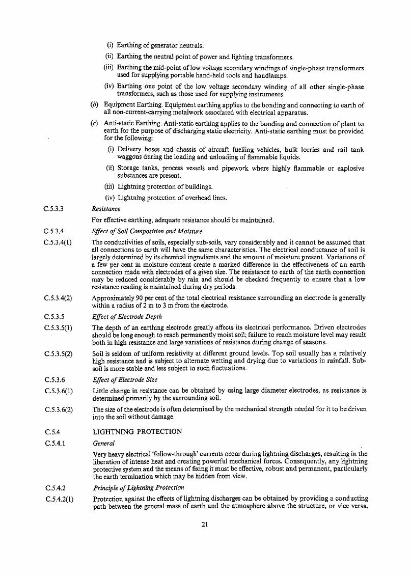
B.3.2.5 The exposed edge of the foundation pad should be sloped away from the tank with a fall of notless than 1 in 6 across a strip not less than 500 mm wide, and then sloped down to the bund floorat 1 in 1.5. After the water test, the pad top surface should be trimmed to provide a space belowthe bottom plate edge for the perimeter seal: refer to diagram B.5.4.4.
B.3.2.6 An alternative means of providing a continuous level support for the tank edge, with a firmlocation of the peripheral seal incorporating assured water-shedding, is a reinforced concretekerb ring built in the top layers of the pad. Construction should be in accordance with theBuilding (Construction) Regulations. Refer to diagram B.5.4.4.
B.3.3 Concrete Ring Wall Foundations
B.3.3.1 Concrete ring wall foundations are particularly suited to natural ground conditions where it isnecessary to distribute the loads deriving from the tank shell. In addition to adequatelydistributing the vertical loading, the ring wall should be designed to carry the horizontal forcesproduced by. the contained material under the surges during tank filling. In general the provisionsof Appendix B to A.P.I Standard 650 will apply, but structural design of the reinforced concretesection should comply with the provisions of the Building (Construction) Regulations. Attentionis drawn to the particular problem of temperature movement and shrinkage within the ring walland, irrespective of the reinforcement required to resist the load system, sufficient horizontal steelshould be provided in the faces of the wall to distribute the shrinkage cracking. Vertical bars orlinks should be provided at suitable centres in accordance with the provisions of the Building(Construction) Regulations.
10
B.3.3.2 The ring wall should not have any perforations or penetrations.
B.3.3.3 If the ring wall is expected to settle under working load and is surrounded by concrete pavingwithin a bunded area, a suitable flexible sealed joint should be provided at paving level.
B.3.3.4 Ring walls may conveniently be used on top of raft foundations (B.3.4.) or pile caps (B.3.5.).They may serve to lift the tank to a higher elevation where this is operationally desirable, and alsoto anchor tall tanks against overturning by wind and to resist uplift due to high internal pressure.
B.3.4 Concrete Raft Foundations
B.3.4.1 Concrete raft foundations may be considered where the tank structure is sited on ground capableof considerable settlement under load. Where large differential settlement is possible, for examplein areas of reclamation, the design of the raft should be based upon an assessment of thedisposition and distribution of loads and contact pressures. Tilting of the raft under load and itseffect on the tank structure carried should also be considered.
B.3.5 Piled Foundations
B.3.5.1 Where piled foundations are considered, the design and construction should comply with theappropriate provisions of the Building (Construction) Regulations and be in accordance withSection 7 of C.P. 2004. The effect of negative skin friction due to settlement of fill materialthrough which the piles pass should be considered. Also, the possible effects of the group actionof the piles should be taken into account.
B.3,6 Vibro-Compacted Foundations
B.3.6.1 Vibrp-compaction may be an economical alternative to piling or other methods of improving thebearing capacity of granular soils or sites. The depth to which compaction can be achieved islimited by consideration of withdrawal of the vibrating unit. The zone of influence of the vibratordepends on its energy output and the soil structure, and may be of the order of 900 mm to 1 200mm from the vibrating source.
B.3.6.2 Vibro-replacement is the process whereby a vibrator is used to mix coarse granular material intoa soft silt or clay or weak compressible fill material, thus forming columns or piles of compactedgranular material within the soft ground. It should be remembered that these granular columnsmay well act in a similar manner to piles and that it may be necessary to treat the tank foundationas a piled design and not as a flexible foundation on compacted ground.
B.3.7 Settlement
B.3.7.1 Probable settlements should be calculated from the soil properties derived from the siteinvestigation, and from the calculation load system applied by the foundation and fill material.The effect of the expected settlement on the tank structure and on connecting pipework should beevaluated and provision made in the detail design for this settlement. Particular care should betaken when calculation indicates a differential settlement between the tank foundation and thefoundations of connecting structures, such as pipe tracks, etc. Where the foundations of ta,nkssettle under load, this settlement may affect the foundations of adjoining structures and buildingsand due assessment should be made of this possibility; in addition, the spread of load from tankfoundations should be considered in relation to adjoining tanks and buildings, both existing andplanned. Consideration of this aspect of foundation design may influence the spacing of tanksand the layout of storage areas and may override the minimum spacing criteria recommended inthe LP.'s Marketing Safety Code.
B.4 BUNDED AREAS
B.4.1 General
B.4.1.1 Tanks containing oil or petroleum products which are liquid or solid at ambient temperaturesand atmospheric pressure should be within a bunded area constructed to contain the maximumspillage from the largest tank. Products which do not pose a risk of environmental pollution, andare not classified as Cat 5 D.G. within the meaning of the D.G. (Classification) Regs. Cap. 295,may be excluded from this requirement
B.4.2 Volume Enclosed by Bund Walls
B.4.2.1 For Class 1 products, the containment volume of the bunded area should be not less than 105%of the maximum operating capacity of the largest tank, excluding the displacement of all othertanks and foundations. The bunded area should be self-contained with no weirs or overflows toother areas, but it may contain tanks storing Class 2 and Class 3 products.
11
B.4.2.2 For Class 2 and Class 3 products, the containment volume of the bunded area should be not lessthan 100% of the maximum operating capacity of the largest tank, excluding the displacement ofall other tanks and foundations. The volume of any other bunded area may be taken into accountif connected by relief spillways or weirs which are adequate to carry the overflow resulting fromthe largest tank releasing 100% of its contents in 15 minutes.
B.4.3 Bund Wall Construction
For the purpose of calculating the strength and stability of embankments or walls, the density ofpetroleum oil should be taken as equal to that of water.
B.4.3.1 Earth or Rock Bund Construction
B.4.3,1(1) Where it is proposed to use excavated material or natural rock material to form a bund, theprofile should conform with the provisions of B.S. 6031.
B.4.3.1(2) Compaction of the material should be carried out with appropriate plant in layers generally inaccordance with B.S. 6031. The material should be selected, graded and placed to provide anembankment impermeable to petroleum products unless an impermeable surfacing is to beapplied.
6.4,3.1(3) On completion, the inner sloping face of the bund should be protected from erosion by concreteblinding, precast slabbing or some other suitable material. If the embankment construction itselfis not impermeable, this facing should be capable of resisting penetration by oil at the full designhead. The top surface and outer face may be covered with any erosion-resistant material such aschunam plaster, or grass may be grown and maintained.
B.4.3.1(4) An acceptable facing for bund embankments is reinforced sand/cement render which shouldbe:—
(a) A mixture of 4 parts sand to 1 part cement with minimum water for workability, the sandbeing the type normally used in reinforced concrete construction;
(6) Not less than 50 mm thick
(c) Reinforced with light wire mesh
(d) Laid in panels with sealed movement joints at suitable intervals; horizontal joints will notnormally be required.
The inclusion of a waterproofing admixture is recommended good practice.
B.4.3.1(5) Good quality well-maintained chunam plaster is acceptable for slope protection above maximumoil-spill level.
B.4.3.2 Gravity Walls
B.4.3.2(l) Gravity bund walls can be constructed either in mass concrete or masonry and should bedesigned to give a factor of safety against sliding of not less than 1.5 and a factor of safety againstover-turning of not less than 2.0 under the full head of retained oil. Due note should be taken, inthe detail design, of the behaviour of concrete and masonry over the range of temperature to beexperienced and suitable expansion/contraction joints included. All such joints should beconstructed so as to prevent the passage of oil.
B.4.3.2(2) If masonry walls are used, and where the masonry is capable of absorbing oil and becomingsaturated, the wall should be rendered impermeable. A dense sand/cement oil resisting render isone suitable material.
B.4.3.3 Reinforced Concrete. Prestressed Concrete and Reinforced Masonry Walls
B.4.3.3(1) Reinforced concrete bund walls should be designed in accordance with the relevant sections ofC.E.C.P. 2 and the Building (Construction) Regulations which apply to retaining walls andreinforced concrete structures respectively.
B.4.3.3(2) Prestressed concrete bund walls should be designed in accordance with the relevant sections ofC.E.C.P. 2 and CP 115 which apply to retaining walls and prestressed concrete structuresrespectively.
B.4.3.3(3) Reinforced masonry bund walls should be designed in accordance with the relevant section ofC.E.C.P. 2 and BS 5628. Where the masonry used is capable of absorbing oil and becomingsaturated, a dense sand/cement render, which is resistant to oil, should be applied.
B.4.3.3(4) Where precast concrete elements are used, the provisions of CP 116 should be followed inaddition to any relevant section of C.E.C.P. 2.
12
8.4,3.3(5) All joints within a bund wall are a potential source of weakness and should be located andformed to take into account prevailing soil conditions, thermal and shrinkage movements.
8.4.3.3(6) All wall and base joints should be provided with a water seal and properly bonded atintersections.
8.4.3.3(7) Special care should be taken to obtain thorough compaction and to avoid segregation of theconcrete along the joint plane and around the joint.
8.4.3.3(8) Any laitence formed on the surface of a joint should be removed by a fresh water spray andbrushing to expose the coarse aggregate before further concreting commences.
8.4.3.3(9) An expansion joint should occur within a bund wall at intervals not exceeding 30 m.
8.4.3.3(10) Wall fixings or fasteners shall not be allowed to penetrate a water seal.
8.4.3.3(11) Jointing materials should be provided in accordance with Appendix D of B.S. 5337.
8.4.4 Bund Floor Construction
B.4.4.1 General
The floor construction of a bunded area should be capable of preventing oil penetration into theground below the bund floor under the design head of oil. Particular attention should be given tothe specification for the floor construction when the bund is sited on reclaimed land andcontamination of the reclamation material would lead to the escape of oil into the sea or adjacentwater courses.
8.4.4.2 Materials
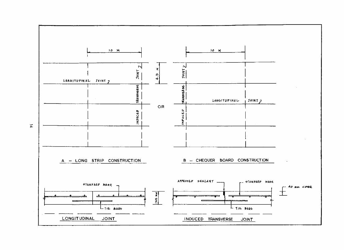
8.4.4.2(1) Concrete floor construction laid on solid ground should be a thickness of not less than 125 mmreinforced and constructed in accordance with B.S. 5337; the reinforcement should be:—
Min. 0.2% high tensile steel in each direction, or
Min. 0.25% mild steel in each direction, or
Square mesh not less than A 252 to B.S. 4483
Concrete cover should be not less than 40 mm.
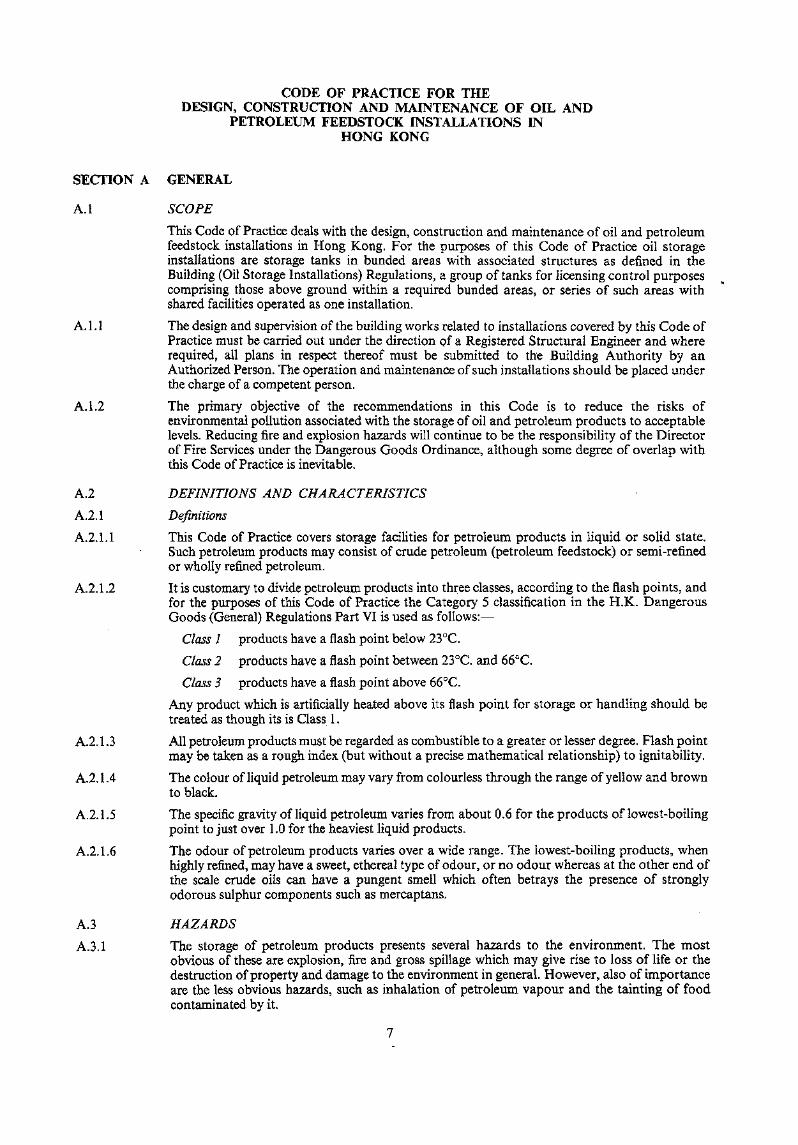
B.4.4.2(2) Joint spacing and curing methods should be such as to ensure that drying shrinkage is controlledand that cracking does not occur over the area of the pour.
8.4.4.2(3) Joints between bays should be sealed to prevent penetration of oil and rainwater. Jointingmaterials should be in accordance with B.S. 5337 Appendix D. Bitumen should not be used as asealant in Class 1 bunds and if used elsewhere should be renewed when it has cracked throughembrittlement: annual repair may be necessary. Other joint-sealing materials should be resistantto the oil products and to the deteriorating effect of strong sunlight.
8.4.4.2(4) Membranes of polythene, neoprene or other sheet materials may be considered necessary incertain locations to satisfy the requirement to contain oil spillage. In such circumstances, it isessential that a blanket of suitable material be provided to protect the membrane fromdeterioration as a result of exposure to ultra-violet light and accidental physical damage.Membranes laid in sheet form should be joined sheet to sheet in a manner which renders themeffectively continuous and impermeable. Such membranes should not be relied upon wheredifferential settlement in tank foundations may cause them to rupture.
8.4.4.2(5) Asphaltic and bituminous specifications may be considered for bund floor construction, butshould be prepared with the solvent effects of the stored oil products in mind and should also takeinto account the possible deterioration under conditions of exposure to strong sunlight. Surfacelayers of reflective material should be considered.
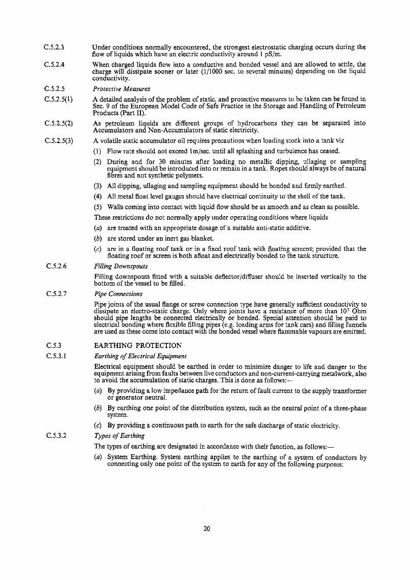
8.4.4.2(6) Local material, such as compacted layers of weathered granite and chunam plaster, may beappropriate for bund floor construction, but should be suitably tested against the design oil headwhere they are relied upon to prevent the permeation of oil into the ground below. Wherenaturally occurring or quarried rock material is used in the consolidated layer to form the bundfloor, grading of the material selected is vital. Ideally, the material should be widely graded withan excess of fines so that when laid and compacted it forms a dense layer in which the voids havebeen filled with fine material, and plant for compaction should be selected with this in mind.Compaction should be carried out in accordance with the provisions of B.S. 6031 and the surfacerolled to a smooth hard finish to the required drainage falls. The finished construction thicknessshould not be less than 300 mm but the factors discussed in B.4.4.3 should be considered inarriving at a suitable figure.
13
M M
AU
V-:r
fi
I<r
5.OR
cj
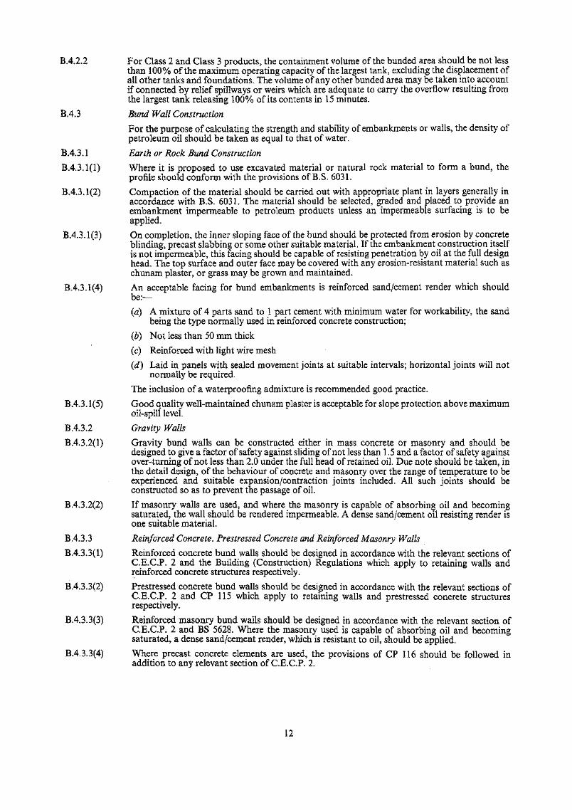
A - LONG STRIP CONSTRUCTION B - CHEQUER BOARD CONSTRUCTION
£'
LONGITUDINAL JOINT NDUCED TRANSVERSE JOINT

8.4.4.2(7) If there is a likelihood of the finished surface of a bund floor deteriorating with time or sufferingdamage due to climate conditions, then it is desirable that the surface be protected by a layer ofstronger material such as chunam plaster or cement stabilized soil. Any such layer should beregarded as a protective coating only, making no contribution to the bund floor impermeability,in view of its liability to severe cracking and disintegration, the reinforced render in B.4.3.1(4) isnot suitable as a floor surface.
8.4.4.2(8) Where the substratum immediately beneath the proposed bund floor construction has large openvoids, the use of compacted crushed rock, even if it complies with the recommendations of8.4.4.3 below is not appropriate because fines may be washed out of the floor layer to formswallow holes. The use of well-compacted fill as a base for a concrete bund floor is, however,permissible.
B.4.4.3 Permeability of Bund Floor Construction
B.4.4.3(l) Where bund floors are constructed with an impermeable membrane, it is necessary that themembrane be effectively continuous under the tanks and effectively joined to the wallconstruction. In the case of installations where the tanks are seated on a foundation covered by abitumen/sand blanket (see B.S. 2654, Fig. 44), the membrane incorporated in the floorconstruction of the bunded area should be effectively joined to the bitumen/sand blanket at theperimeter of the tank foundation.
8.4.4.3(2) Where compacted granular or rock materials are used for bund floor construction, the degree ofpenetration of this material by escaping oil is a function of the head of oil, the time over which thefloor construction is exposed to that head of oil, the viscosity of the oil, and the permeabilitycharacteristics of the material. Thus, if an oil spill occurs in this type of bunded area, it isnecessary to pump out the free oil from the bund into alternative tanks or containers as soon aspossible, and the bund floor construction should be such as to allow a period of 48 hours for thispurpose.
8.4.4.3(3) It is therefore recommended that in 48 hours the oil should not be able to penetrate more than50% of the thickness of the floor construction.
B.4.4.3(4) Permeability tests should be carried out at the time of design on samples of the specifiedconstruction to ensure that this requirement can be met. After an oil spill any area of bund floorsaturated with oil should be excavated to the depth of saturation and the contaminated materialremoved. New material should be rolled in to reconstitute the floor construction.
B.4.4.4 Testing the Permeability of the Bund Floor Construction
B.4.4.4(l) If any material of known impermeability is used, then further permeability testing will beunnecessary.
6.4.4.4(2) The specified material for compacted fill bund floors should be tested for compliance with thepermeability requirements of Section B.4.4.3 of this Code of Practice. Where the construction ofthe bund floor is subject to competent and continuous supervision, it may only be necessary totest the proposed specification in the laboratory. If, however, there is a lack of suitable sitesupervision or it is thought that the material on which a bunded area is to be constructed will besufficiently impermeable without further treatment, it will be necessary to perform field tests toprove the relative impermeability of this bund floor. This can be done either by in situpermeability testing, by laboratory testing of samples taken from the bund floor, or by a full scalefield trial in which the bunded area is flooded and the rate of leakage is measured. If in situpermeability tests or laboratory tests on selected samples are to be performed, then expert adviceshould be sought and it should be remembered that isolated samples are not likely to berepresentative.
8.4.4.4(3) Sufficient tests should, therefore, be performed to ensure that a statistically significant result isobtained.
8.4.4.4(4) Field trials may well be prohibitively expensive or else impracticable for some other reasons.However, if performed, they will give a reliable indication of the retaining capacity of the bundfloor concerned.
8.4.4.4(5) Suitable laboratory tests are described in Appendix I to this Code of Practice and in situpermeability tests are outlined in Appendix II. Expert advice should be sought before embarkingupon either a laboratory or in situ permeability testing programme.
15
B.5 TANK DESIGN
B.5.1 General
B.5.1.1 The design, fabrication, site erection and testing of above-ground vertical steel welded storagetanks should comply with B.S. 2654 or A.P.L Standard 650 as appropriate. For above-groundhorizontal steel storage tanks, the provisions of B.S. 2594 and the Appendix to B.S. 799 Part 5should apply.
B.5.1.2 Reinforced concrete elements associated with the steel tank construction should be designed inaccordance with the Building (Construction) Regulations.
B.S. 1.3 Concrete tanks should be constructed in accordance with B.S. 5337 "The structural use ofconcrete for retaining aqueous liquids".
B.5.2 Wind Loading
For stability and detail calculations for above-ground storage tanks, the wind loading to beconsidered should be that given in the Code of Practice on Wind Effects referred to in theBuilding (Construction) Regulations, appropriate to the height, diameter and shape of the tanks.
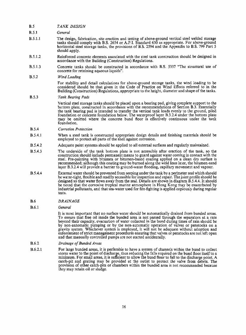
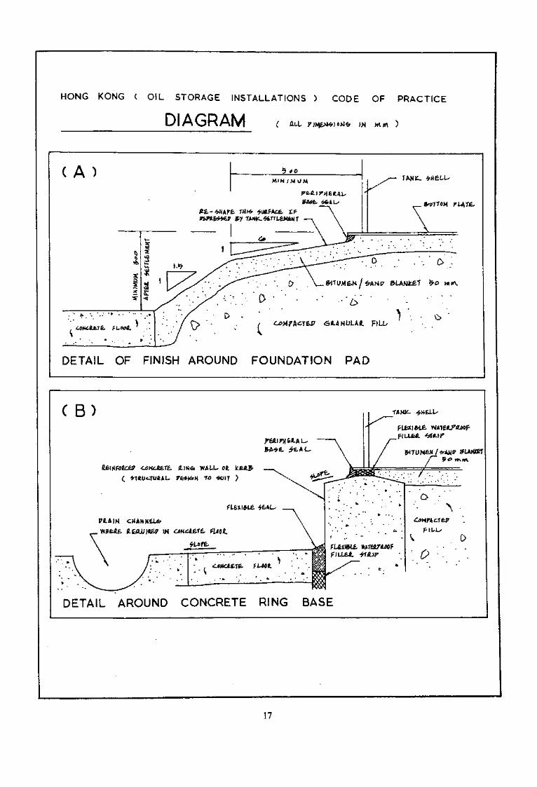
B.5.3 Tank Bearing Pads
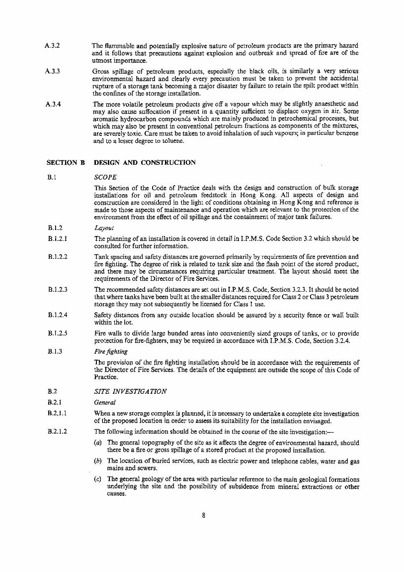
Vertical steel storage tanks should be placed upon a bearing pad, giving complete support to thebottom plate, constructed in accordance with the recommendations of Section B.3. Essentiallythe tank bearing pad is intended to transfer the vertical tank loads evenly to the ground, piledfoundation or concrete foundation below. The waterproof layer B.3.2.4 under the bottom platemay be omitted where the concrete bund floor is effectively continuous under the tankfoundation.
B.5.4 Corrosion Protection
B.5.4.1 When a steel tank is constructed appropriate design details and finishing materials should beemployed to protect all parts of the shell against corrosion.
B.5.4.2 Adequate paint systems should be applied to all external surfaces and regularly maintained.
B.5.4.3 The underside of the tank bottom plate is not accessible after erection of the tank, so theconstruction should include permanent means to guard against water coming in contact with thesteel. Pre-painting with bitumen or bitumen-based coating applied on a clean dry surface isrecommended; although this coating may be burned along the weld lines later, the bitumen-sandlayer B.3.2.4 will provide a barrier to ground-water flooding, capillary movement and vapour.
B.5.4.4 External water should be prevented from seeping under the tank by a perimeter seal which shouldbe water-tight, flexible and readily accessible for inspection and repair. The joint profile should bedesigned so that water flows away from the seal. Details are shown in diagram B.5.4.4. It shouldbe noted that the corrosive tropical marine atmosphere in Hong Kong may be exacerbated byindustrial pollutants, and that sea-water used for fire-fighting is applied copiously during regulartests.
B.6 DRAINAGE
B.6.1 General
It is most important that no surface water should be automatically drained from bunded areas.To ensure that free oil inside the bunded area is not passed through the separators at a ratebeyond their capacity, evacuation of water collected in the bund during times of rain should beby non-automatic pumping or by the non-automatic operation of valves or penstocks on agravity system. Whichever system is employed, it will not be adequate without adoption andenforcement of strict management procedures ensuring that valves or penstocks are not left openand that manually controlled pumps are not started accidentally.
B.6.2 Drainage of Bunded Areas
B.6.2.1 For large bunded areas, it is perferable to have a system of channels within the bund to collectstorm water to the point of discharge, thus reducing the falls required on the bund floor itself to aminimum. For small areas, it is sufficient to allow the bund floor to fall to the discharge point. Acatch-pit and grating may be provided at the outlet to protect the valve from debris. Theprovision of other catch-pits or chambers within the bunded area is not recommended becausethey may retain oil or sludge.
16
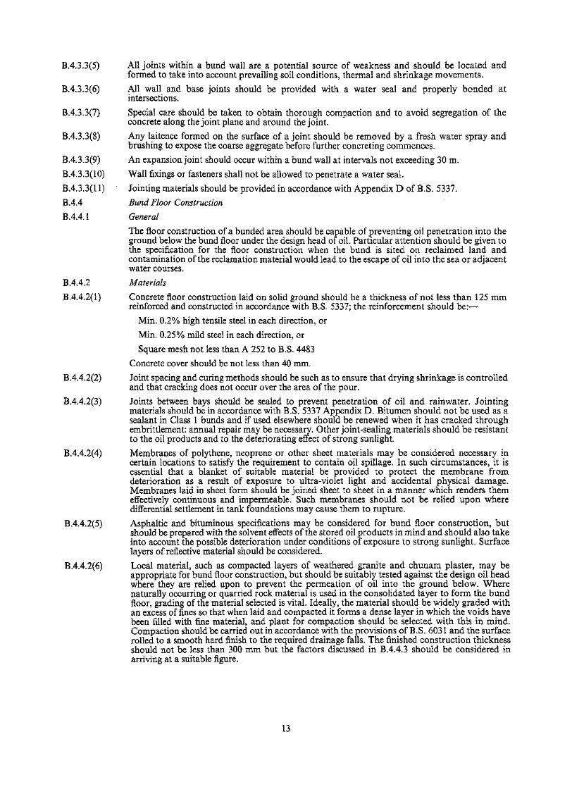
HONG KONG ( OIL STORAGE INSTALLATIONS ) CODE OF PRACTICE
All )N
( A )
DETAIL OF FINISH AROUND FOUNDATION PAD
C B)
\ •
• o
DETAIL AROUND CONCRETE RING BASE
17
B.6.2.2 The extraction of water from the bunded area should be:—
(a) By a non-automatic pumped system. That is to say that the pumps should not switch onautomatically but should be activated manually as a normal maintenance procedurefollowing rain.
OR
(b) By a gravity system controlled by manually operated valves or penstocks. Such valves andpenstocks may be motorized but should require manual activation as a normal maintenanceprocedure following rain.
OR
(c) By other methods governed by maintenance procedures and which fulfil the recommenda-tions contained in this Code of Practice.
B.6.2.3 All storm water removed from bunded areas should pass through purpose designed separators orinterceptors having a separating capacity to satisfy the maximum rate of flow possible throughthe draw-off system.
B.6.2.4 A valve or penstock should be fitted between the outlet weir of the separators and the dischargepoint into the sewerage system or outfall.
B.6.3 Tank Roof Drainage
Primary and emergency drainage should be provided for "floating roof" tanks generally inaccordance with the provisions of B.S. 2654. However, the number and size of primary drainsand the number and size of the outlets should be determined to suit the maximum rainfallintensity predicted for a "ten years storm" in Hong Kong. Account should be taken of anylimitations of head over the outlets arising from the structural design of the roof. The designshould also be compatible with the operation of fixed water installations, for fire protection,where they exists.
B.6.4 Valves and Penstocks
B.6,4.1 Valves and penstocks controlling the evacuation of storm water from bunded areas should belocated on the outside of the bund and discharge into an open pit or channel so that the flow isclearly visible. All valves and penstocks should have a direct spindle operation and shouldincorporate an indicating device (for example, a "rising spindle" or an indicating headstock)which clearly shows when the valve or penstock is in a fully closed position.
B.6.4.2 The valve or penstock at the separator outlet should also clearly indicate its closed position by adirect device. The location of the valve should envisage the need for operation if the separator isfilled to the brim during an oilspill emergency.
B.6.5 Interceptors and Separators
B.6.5.1 Separators provided in accordance with B.6.2.3 should be designed in general accordance withthe A.P.I, or LP. recommendations. To provide ready access for cleaning and easy inspection, thechambers are best left open, with a guardrail or wall around the perimeter. Where the top ispartially covered, sufficient unobstructed openings should be incorporated to give a clear view ofthe inlet flow, a portion of each chamber, and the outlet flow.
B.6.5.2 Separators should be located outside the bunded area; more than one unit may be provided forlarge installations. All water from within the bunded area should pass through the separator. Abypass should not be provided in any circumstances.
B.6.5.3 Each separator should be provided with a means of removing the floating oil.
B.6.6 Unbunded Areas
B.6.6.1 In high risk unbunded areas, such as loading bays, where small operational spills are probable,surface water drains should be provided with an interceptor or separator before discharging intothe public storm water sewerage system, natural water course or the sea.
B.6.6.2 Pipelines outside bunded areas should where practicable be grouped, and it is good practice tolocate them over a paved strip with kerb walls to retain any oil spillage,
18
SECTION C ASSOCIATED EQUIPMENT
C.I FENCING
For reasons of security and safety the area of the storage installation, including tanks, pumpingequipment and loading and unloading facilities should be enclosed by a secure fence whichshould be at least 1.8 m high constructed within the lot. For safety reasons, the fence should haveat least two means of exit, separated by at least 5 m, to provide escape routes in case ofemergency. Gates should be capable of opening outwards in an emergency and should not beself-locking.
C.2 TANK FITTINGS AND CONNECTIONS
C.2.1 Pipes, valves and pipe fittings should be fabricated to the requirement of the appropriate BritishStandard or A.P.I. Standard and should have an adequate safety factor for service conditions.Pipe-lines should preferably be of all-welded construction. They should be installed inaccordance with sound engineering principles and practice, with the necessary provision madefor thermal expansion or contraction.
C.2.2 Pipelines connected to major tank units should be provided with sufficient flexibility to allow forany expected settlement. Flanges should be of adequate strength for the pressure requirements ofthe line at the maximum temperatures likely to be experienced in service. Mating flanges shouldbe of similar form and materials. Isolating flanges, blanks or spades used to segregate sections ofa pipe-line system should be of adequate strength and embody a means of indicating clearly theirlocation and setting.
C.3 VALVES
C.3.1 Valves used should preferably give full bore opening and be constructed in materials resistant tocorrosion or abrasion from the product they control. They should be designed with a suitablefactor of safety relative to the pressures and stresses likely to be met in service. Glands should bedesigned to permit repacking without removing the valve from service.
C.3.2 The bodies of terminal valves on jetties and in installations should be of steel constructionthroughout. Where valves are not of the rising spindle type, they should embody a clearindication of valve position. In cases where the products handled may solidify in low temperatureweather conditions (e.g. heavy fuel oil), the valves should be capable of being heated by steam orother safe means.
C.4 VENTING REQUIREMENTS
Venting requirements vary according to the vapour pressure of the product stored. For fixed rooftanks vents should be fitted in compliance with B.S. 2654, Section 6.6. The same British Standardalso specifies venting requirements for floating roof tanks in Section 7.9.
C.5. ELECTRICAL
C.5.1 GENERAL
C.5.1.1 Petroleum is a high risk product because of its flammable characteristics in as much as it isvolatile and readily forms vapours that mix with air. It is most important therefore to take allprecautions to avoid the risk of creating any source of ignition when the condition of a hazardousatmosphere prevails in the ullage space of a tank.
C.5.1.2 All electrical equipment should be in accordance with the I.P. Electrical Safety Code.
C.5.2 STATIC ELECTRICITY
C.5.2.1 Electrostatic generation in petroleum liquids is caused by:—
(1) the fast passage of liquid through pipes or filters, the presence of impurities such as waterdroplets, rust particles and other trace compounds increasing static generation.
(2) settling of water droplets or solid particles separating out in a tank containing a petroleumliquid.
(3) the bubbling of gas or air through a petroleum liquid.
C.5.2.2 The degree of charge is essentially determined by the flow rate in pipelines and productconductivity.
19
C.5.2.3 Under conditions normally encountered, the strongest electrostatic charging occurs during theflow of liquids which have an electric conductivity around 1 pS/m.
C.5.2.4 When charged liquids flow into a conductive and bonded vessel and are allowed to settle, thecharge will dissipate sooner or later (1/1000 sec. to several minutes) depending on the liquidconductivity.
C.5.2.5 Protective Measures
C.5.2.5(l) A detailed analysis of the problem of static, and protective measures to be taken can be found inSec. 9 of the European Model Code of Safe Practice in the Storage and Handling of PetroleumProducts (Part II).
C.5.2.5(2) As petroleum liquids are different groups of hydrocarbons they can be separated intoAccumulators and Non-Accumulators of static electricity.
C.5.2.5(3) A volatile static accumulator oil requires precautions when loading stock into a tank viz
(1) Flow rate should not exceed Im/sec. until all splashing and turbulence has ceased.
(2) During and for 30 minutes after loading no metallic dipping, ullaging or samplingequipment should be introduced into or remain in a tank. Ropes should always be of naturalfibres and not synthetic polymers.
(3) All dipping, ullaging and sampling equipment should be bonded and firmly earthed.
(4) All metal float level gauges should have electrical continuity to the shell of the tank.
(5) Walls coming into contact with liquid flow should be as smooth and as clean as possible.
These restrictions do not normally apply under operating conditions where liquids
(a) are treated with an appropriate dosage of a suitable anti-static additive.
(b) are stored under an inert gas blanket.
(c) are in a floating roof tank or in a fixed roof tank with floating screens; provided that thefloating roof or screen is both afloat and electrically bonded to the tank structure.
C.5.2.6 Filling Downspouts
Filling downspouts fitted with a suitable deflector/diffuser should be inserted vertically to thebottom of the vessel to be filled.
C.5.2.7 Pipe Connections
Pipe joints of the usual flange or screw connection type have generally sufficient conductivity todissipate an electro-static charge. Only where joints have a resistance of more than 107 Ohmshould pipe lengths be connected electrically or bonded. Special attention should be paid toelectrical bonding where flexible filling pipes (e.g. loading arms for tank cars) and filling funnelsare used as these come into contact with the bonded vessel where flammable vapours are emitted.
C.5.3 EARTHING PROTECTIONC.5.3.1 Earthing of Electrical Equipment
Electrical equipment should be earthed in order to minimize danger to life and danger to theequipment arising from faults between live conductors and non-current-carrying rnetalwork, alsoto avoid the accumulation of static charges. This is done as follows:—
(a) By providing a low impedance path for the return of fault current to the supply transformeror generator neutral.
(b) By earthing one point of the distribution system, such as the neutral point of a three-phasesystem.
(c) By providing a continuous path to earth for the safe discharge of static electricity.C.5.3.2 Types of Earthing
The types of earthing are designated in accordance with their function, as follows:—
(a) System Earthing. System earthing applies to the earthing of a system of conductors byconnecting only one point of the system to earth for any of the following purposes:
20
(i) Earthing of generator neutrals.
(ii) Earthing the neutral point of power and lighting transformers.
(iii) Earthing the mid-point of low voltage secondary windings of single-phase transformersused for supplying portable hand-held tools and handlamps.
(iv) Earthing one point of the low voltage secondary winding of all other single-phasetransformers, such as those used for supplying instruments.
(b) Equipment Earthing. Equipment earthing applies to the bonding and connecting to earth ofall non-current-carrying metalwork associated with electrical apparatus.
(c) Anti-static Earthing, Anti-static earthing applies to the bonding and connection of plant toearth for the purpose of discharging static electricity. Anti-static earthing must be providedfor the following:
(i) Delivery hoses and chassis of aircraft fuelling vehicles, bulk lorries and rail tankwaggons during the loading and unloading of flammable liquids.
(ii) Storage tanks, process vessels and pipework where highly flammable or explosivesubstances are present.
(iii) Lightning protection of buildings,
(iv) Lightning protection of overhead lines.
C.5.3.3 Resistance
For effective earthing, adequate resistance should be maintained.
C.5.3.4 Effect of Soil Composition and Moisture
C.5.3.4(1) The conductivities of soils, especially sub-soils, vary considerably and it cannot be assumed thatall connections to earth will have the same characteristics. The electrical conductance of soil islargely determined by its chemical ingredients and the amount of moisture present. Variations ofa few per cent in moisture content create a marked difference in the effectiveness of an earthconnection made with electrodes of a given size. The resistance to earth of the earth connectionmay be reduced considerably by rain and should be checked frequently to ensure that a lowresistance reading is maintained during dry periods.
C.5.3.4(2) Approximately 90 per cent of the total electrical resistance surrounding an electrode is generallywithin a radius of 2 m to 3 m from the electrode.
C.5.3.5 Effect of Electrode Depth
C.5.3.5(l) The depth of an earthing electrode greatly affects its electrical performance. Driven electrodesshould be long enough to reach permanently moist soil; failure to reach moisture level may resultboth in high resistance and large variations of resistance during change of seasons.
C.5.3.5(2) Soil is seldom of uniform resistivity at different ground levels. Top soil usually has a relativelyhigh resistance and is subject to alternate wetting and drying due to variations in rainfall. Sub-soil is more stable and less subject to such fluctuations.
C.5.3.6 Effect of Electrode Size
C.5.3.6(l) Little change in resistance can be obtained by using large diameter electrodes, as resistance isdetermined primarily by the surrounding soil.
C.5.3.6(2) The size of the electrode is often determined by the mechanical strength needed for it to be driveninto the soil without damage.
C.5.4 LIGHTNING PROTECTION
C.5.4.1 General
Very heavy electrical 'follow-through' currents occur during lightning discharges, resulting in theliberation of intense heat and creating powerful mechanical forces. Consequently, any lightningprotective system and the means of fixing it must be effective, robust and permanent, particularlythe earth termination which may be hidden from view.
C.5.4.2 Principle of Lightning Protection
C.5.4.2(l) Protection against the effects of lightning discharges can be obtained by providing a conductingpath between the general mass of earth and the atmosphere above the structure, or vice versa,
21
so that discharges can pass without producing dangerous potential differences in, on, or near thestructure.
C.5.4.2(2) A structure may be built wholly or partly of conducting material, which can form its ownlightning protection system; otherwise protection should be provided accordingly. The extent ofsuch provision depends upon the zone of protection desired, the prevalence of lightning in thelocality and the nature and importance of the building.
C.5.4.3 Down-conductors
C.5.4.3(l) If the height of the air termination gives a sufficient zone of protection, structures with base areasof up to 93 m2 may be equipped with one down-conductor.
C.5.4.3(2) It is recommended that a least one additional down-conductor should be installed for every 280m2 of base area in excess of 93 m2 or at least one down-conductor per 30 m of perimeter,whichever is the smaller. Down-conductors should be spaced evenly around the outside walls ofthe structure.
C.5.4.3(3) Down-conductors should follow the most direct path between the air and the earth termination.There should be no up-turn in any down-conductor and bend radii should be as great as possible.
C.5.4.4 Conductor Joints
C.5.4.4(1) The lightning protection system should have as few joints as possible. Where joints are necessary,they should be mechanically and electrically sound.
C.5.4,4(2) Joints for copper strip should be tinned, soldered and double riveted or welded. Clamped orbolted joints should only be used on test points or on joints to existing material, but joints for rodmay be of the clamped or screwed type.
C.5.4.5 Testing Points
C.5.4.5(1) Each down-conductor should be provided with a conveniently located testing point protectedfrom unauthorized interference.
05.4.5(2) No connection, other than direct to an earth electrode, should be made below a testing point.
SECTION D OPERATION AND MAINTENANCE
D.I OPERATION
D. 1.1 The Building Authority must be satisfied that the operating instructions for each installation aresatisfactory before granting a licence. For the purposes of this Code the instructions need coveronly those procedures which are pertinent to avoidance of environmental pollution.
D.I.2 Operating instructions should be as simple and specific as practicable. Where various tasks arecarried out at increasing levels of responsibility, the division of work should be reflected in theinstruction for each grade of personnel, so that every essential operation is provided for. Ageneral statement of aims and objectives may be desirable for staff understanding, but should notbe used as a substitute for adequate description of each task a person is expected to perform.
D. 1.3 Personnel should be trained for the tasks assigned to them and be given an understanding of thereasons behind various procedures. It is desirable that they also understand related operationseven though they are not responsible for them, as such understanding reduces the risk of accidentthrough ignorance or negligence.
D.1.4 For licensing purposes the operation instructions are written in English, but it is essential thatthey be also written in Chinese., and explained to the workmen by a member of the licensedoperator's staff who himself knows the procedures and is proficient in English and Chinese.
D.I.5 Instructions should cover the following items; description of the actual procedure will dependupon the particular physical characteristics and management control of each installations.
D.L5.1 Handle bulk petroleum in accordance with I.P.M.S. Code Section 3.4.1.
D.I.5.2 Operate the bunded areas drainage valves to ensure that:—
(a) Stormwater is never allowed to accumulate to a depth which reaches the steel tank bases;
(b) the valves are always kept closed except when actually discharging water under supervisionand a prominent notice displayed to this effect, and
22
(c) they are checked and closed at the end of each day, and
(d) they are closed whenever a tank within the bund is receiving stock.
D. 1.5.3 Observe the oil interceptor (separator) during operation to check that the outflow is free of oil; ifthe discharge is polluted close all inlets and the outlet valve, then clean out the floating oil beforereopening the valve.
D.I.5.4 Skim out the oil separators whenever there is an excessive accumulation of oil on the watersurface.
D.I .5.5 Dispose of the recovered oil in a manner which does not cause pollution.
D.I.5.6 Clean out the separated sludge regularly and remove to a controlled tip or other approveddisposal facility. A record should be kept of cleaning dates.
D.I.5.7 Inspect oil separators water level regularly; to ensure that oil cannot pass directly to the outlet.
D.I.5.8 During each regular check, close the separator outlet valve to confirm that it operates easily andshuts tight. This valve may be left open except during an oilspill emergency.
D.I.5.9 Pumps and hose connection points should be located within an area constructed with a concretefloor and perimeter kerbs, with drainage through a sump to separate any oil spillage. The outletvalve to this sump should be kept closed whenever the apparatus is in use. Spilt oil should becleaned up immediately.
D.I.6 Emergency plans for fire or spillage should be kept up to date, and practice drills should be heldregularly. They should include an instruction to inform all relevant Government Departmentsimmediately by telephone in the case of any such emergency.
D.2 MAINTENANCE OF TANKS
D.2.1 Steel tanks should be regularly inspected to disclose any signs of corrosion or movement which, ifleft uncorrected, may lead to eventual structural failure.
D.2.2 An Annual External Inspection should be made as required by the Regulations. During thisexternal inspection the following matters should be considered:
D.2.2.1 External Coating. Where a paint system is used, this breaks down as it ages. Minor spot rustingcan appear very disfiguring but may be tolerated until large areas fail, at which stage completerepainting should be recommended: it may be practicable to postpone 100% repaint by touching-up limited areas but this will depend on the individual case. Other forms of repair such aslaminating resin are equally acceptable.
D.2.2.2 Bottom Joint. The lower 300 mm strip of the tank shell, the welded joint, and the edge of thebottom plate are vulnerable and may be treated separately with a more highly protective coatingor repainted more frequently. The steel should not be covered with a thick layer of any materialwhich may hide corrosion below it: where a thick covering exists it should be removed at selectedpoints and the condition of the steel examined, and if water has penetrated and caused rusting thecovering may need to be completely discarded.
D.2.2.3 Peripheral Base Seal. The flexible seal which prevents water penetrating the interface of tankbottom and foundation pad must be kept fully effective. Even small cracks will allow the passageof sufficient water to sustain corrosion leading to bottom plate failure. Defective seals should becut out and replaced, not merely surface-coated. During this work the opportunity should betaken to examine any exposed base-plate surfaces normally hidden.
D.2.2.4 Perimeter of Bottom Plate. This may be tilted upward due to settlement in the tank foundationpad. If a gap has formed under the edge it should be cleaned out, rust inhibiting paint brushed .orsprayed in, and the gap filled with sand/bitumen mix carefully rammed in, leaving a recess toaccept the flexible seal.
D.2.2.5 Insulation. An external layer of insulation and its sheathing will conceal any corrosion on thesteel underneath. Where such corrosion is suspected, sufficient insulation should be lifted to allowadequate inspection. All joints and perforations in the sheathing should be checked and maderainproof because water inhibits the effectiveness of the insulation. Where the design has proveddeficient, modifications may be required.
D.2.2.6 Earthing Connections should be inspected and any damage or corrosion should be repaired.
D.2.3 Tank Foundations including Concrete Ring Walls should also be noted during the annualinspection, and any signs of settlement or signs of distress investigated and corrected.
23

D.2.3.1 Settlement Records should be checked and where there are indications of significant developmentof differential settlements this should be stated in the inspection certificate, with recommenda-tions for additional monitoring as appropriate. Large tanks on soft ground or reclamations maybe expected to show continuing settlement during the first few years of their use.
D.2.3.2 Foundation Pads may be distorted by settlement, and where the surface does not shed rainwaterrapidly it should be stripped, the pad profile re-shaped, and resurfaced. At this stage it may beadvantageous to give the top surface a substantial cross-fall and form a step at the tank-base edgeto facilitate the insertion of a flexible seal.
D.2.3.3 Pad Surfacing deteriorates in time to the state where it no longer functions as an imperviousmembrane; its replacement by a new surface to B.3.2 specification may be necessary. Where arigid surface of cement plaster or concrete has been used and is in sound condition the joints orcracks may require re-sealing, but if it is extensively broken a more satisfactory repair would becomplete replacement by a new flexible surfacing.
D.2.4 General and Internal Inspections should be carried out within specified maximum time intervals orwhenever there is reason to suspect that a tank has developed serious deterioration which cannotbe detected by external inspection alone. Corrosion of the underside of the bottom plate shouldbe assumed where its outer edge is severely corroded and the flexible seal defective, or whererecent work on the joint has covered a previous long-standing defect, as noted in D.2.2.2.
D.2.4.1 Ultrasonic Measurement of Plate Thickness may be carried out by machines which measure theresidual amount of sound metal, using a probe placed against one cleaned surface. Howeveraccurate the individual readings, each indicates the thickness only at one point and widely-spacedreadings may entirely miss small localized corrosion spots. Ultrasonic readings should not beused as the sole evidence of plate soundness.
D.2.4.2 Bottom Plates may be inspected after the tank has been cleaned and gas freed. The top surface isusually rough from corrosion, and may be undulating due to localized limited settlement in thebase pad having allowed the plate to sag and stretch: when the tank is emptied, some areasrebound upwards forming springy domes.
D.2.4.3 For adequate visual examination, good lighting is essential and flameproof floodlighting shouldbe used in preference to torches. In certain conditions it is possible to see discolourations on thetank floor which may indicate thin spots or pin-hole perforations: these may be quickly tested byhammer-blows, and if they do not fail may be subjected to ultrasonic measurement.
D.2.4.4 Selection of spots for hammering should be made by the certifying engineer or under his directsupervision. For ultrasonic readings, he should personally select not less than 20% of thepositions and give clear instructions for the remainder, and he should also observe a sufficientnumber of the readings to satisfy himself that the operation is properly carried out. Particularattention should be given to positions alongside lap welds.
D.2.4.5 Small pieces of the plate may be cut out for inspection and replaced by new patches welded inplace.
D.2.5 Repairs to Tanks should be carried out by skilled workmen under proper supervision and besubject to the same quality control as that required for new tanks construction.
D.2.5.1 A Water Test should be imposed after completion of the repairs, by filling the tank to itsmaximum capacity and checking the water level for 48 hours. If there is any drop in level thecause should be investigated and corrected, and the tank re-tested. After the satisfactorycompletion of a test the tank may be returned to service.
24

APPENDIX 1
LABORATORY TESTING FOR THEPERMEABILITY OF BUND FLOOR CONSTRUCTION
I. I General
1.1.1 This Appendix gives a brief outline of the more important points to be considered whenlaboratory permeability tests are performed. It is not intended that the following sections shouldbe used as a complete specification for laboratory permeability testing and it is recommendedthat when testing a proposed bund floor design or specification, expert advice should be sought.
1.1.2 Laboratory testing should be carried out by a suitably qualified technician who is fullyconversant with laboratory procedures for the measurement of permeability. Likewise, anEngineer qualified in the field of soil mechanics and foundation engineering, should supervise thesampling and laboratory testing and should advise on the interpretation of the results.
1.2 Method of Testing
1.2.1 The constant head permeability test should be performed on samples of the actual materialproposed for the bund floor construction in a standard permeameter or other suitableinstrument.
1.2.2 If the proposed construction material is of variable quality, it may be necessary to test a sufficientnumber of samples to ensure that a statistically reliable set of results is obtained. Samples testedshould comply with the recommendations of Section 1.3 of this Appendix.
1.2.3 The constant head permeability test should be performed with a petroleum derivative (asappropriate to the class of product to be stored) at heads up to and including the maximum bunddepth, on a sample of the material proposed for the bund floor construction. This sample shouldbe saturated, under a back pressure, with the proposed permeant. It is recommended that at leastfour different heads be applied to each test sample.
(Note: It is necessary to employ a petroleum derivative as the permeant, and not water, since insome soils a layer of the water permeating is absorbed around individual particles andthis will influence the measured value of the coefficient of water permeability. It isdifficult to relate this value to the coefficient of permeability for the flow of ahydrocarbon fuel, which is not absorbed by the soil in this manner.)
1.3 The Test Specimen
1.3.1 The sample material to be permeability tested in the laboratory must be representative of thatproposed for the bund floor construction.
1.3.2 The sample material, prior to saturation with the appropriate petroleum product to be stored,should have a similar moisture content to the minimum which it is expected will exist during theworking life of the bund floor. The sample should be compacted by a dynamic method (e.g. handrammed) and tested at several different porosities so that its permeability at the porosity which itis expected will be achieved on site can be interpolated from the results. To do this, it will benecessary to plot the measured values against:
(l-n)2
where n is the porosity in decimal form.
1.3.3 The size of the samples to be tested will depend on the maximum particle size of the proposedconstruction material. It may be necessary to construct a special permeameter or hydraulicoedometer to accommodate the specified material. The test specimen should have a diameter atleast three times that of the largest particle size, and,in any event, the sample diameter should notbe less than 100 mm. The sample length should be a minimum of 200 mm or four times thediameter of the largest particle within the test specimen.
25
APPENDIX 2
IN SITU TESTING FOR THEPERMEABILITY OF BUND FLOOR CONSTRUCTION
2.1 General
2.1.1 This Appendix gives a brief outline of the in situ tests available for the measurement ofpermeability in the field. It is not intended to form a specification for such tests, and it isrecommended for all but the simplest field trials of a bunded area that expert advice be soughtand a competent soil mechanics technician be employed to perform the tests.
2.1.2 It must be remembered that although the most suitable permeant for use in the field is water, thevalues of permeability obtained by its use may well be misleading. This is because in some soils alayer of water is absorbed around individual particles and this does not flow with the permeatingwater. Consequently, relatively low values may be measured, and it is difficult to relate these tothe values for the flow of a petroleum derivative which does not affect the soil in this manner.
2.1.3 It should also be noted that in general the field methods of measurement of the coefficient ofpermeability have been devised for use below the level of the ground water table or else insaturated soil. This may not always be the case and due allowance should be made in the testprocedures adopted. It is considered that if in unsaturated soils a series of in situ permeabilitytests is performed at the same location these will tend to provide a saturated zone around the testpoint and consequently the test results so obtained will steadily approach the value which wouldbe obtained under ideal saturated conditions.
2.2 Piezometer Testing
2.2.1 This test involves the insertion of a porous piezometer tip into the soil to be tested and themeasurement of the rate of flow of water into (outflow test) or out of (inflow test) the groundunder an applied excess or reduced head of water as is appropriate. The test should be supervisedand interpreted by an expert.
2.2.2 It is important to note that if the bund floor material is of a variable nature, then it will benecessary to perform a considerable number of tests over the whole bunded area in order toobtain reliable results. This is especially important where a bund floor of finite constructiondepth is tested and it is necessary to employ a piezometer of sufficiently small dimensions toeliminate the influence of the nearby soil boundaries. Clearly, in this case, the piezometer test willonly influence an area of the bund floor of small radius compared with the depth of construction.
2.2.3 When performing outflow piezometer tests, it is important to eliminate the possibility ofhydraulic fracture in the soil under test and the false values of the measured permeability whichwill result. This will be achieved by careful control of the applied excess head which should bekept below the critical values given in the technical literature.*
2.3 The Tube Test
2.3.1 This is a simple test to perform in which a tube is driven into the ground, leaving a portion aboveground level which is filled with water. The rate at which water infiltrates into the ground ismeasured, and this is used to determine the coefficient of permeability. This method gives anaverage value of the soil inside and outside the tube. In order to determine the permeability of thesoil surrounding the tube, and eliminate any influence which the disturbed soil inside the tubemay have, it is necessary to remove the soil inside the tube (by means of an auger). The testprocedure and the results obtained should be supervised and interpreted by an expert, and itshould be remembered that the basic theories** for this test assume that it is performed below thewater table.
2.3.2 Other useful methods of in situ measurement are given by Lamb and Whitman (1969)***.
* BJERRUM et al (1972)"Hydraulic fracturing in field permeability testing" Geotechnique 22, No. 2, 319-332
** PREVERT and KJRKHAM (1948)"A field method for measuring the permeability of soil below the water table"Proceedings of the Highway Research Board 28:433^42
*** LAMB and WHITMAN (1969)Soil Mechanics—Wiley, New York
26
2.4 Field Trials
2.4.1 This term is intended to cover the full scale testing of a bunded area by flooding and measurementof the rate of leakage.
2.4.2 Flooding of the bunded area after the storage tanks have been constructed is not recommendedbecause damage to their foundations and baseplates may result, and the use of sea water mayinduce corrosion. Flotation of tanks and pipelines must also be prevented.
27
[HKP] 690.535 H7
/'UK.**690.535 1321387
Hong Kong. Building DevelopmentDepartment.
Date Due 1321387
u \