Embed Size (px)
Citation preview

UNIVERSITY OF NAIROBI
FACULTY OF ENGINEERING
DEPARTMENT OF ELECTRICAL AND INFORMATION
ENGINEERING
TRAFFIC ENGINEERING WITH MULTI-PROTOCOL LABEL SWITCHING
TECHNOLOGY
PROJECT INDEX: PRJ 073
BY
WANJALA ELVIS
F17/1778/2006
SUPERVISORS: DR.CYRUS WEKESA
EXAMINER: DR MANG’OLI
PROJECT REPORT SUBMITTED IN PARTIAL FULFILMENT OF THE REQUIREMENT
FOR THE AWARD OF THE DEGREE
OF
BACHELOR OF SCIENCE IN ELECTRICAL AND ELECTRONIC ENGINEERING OF THE
UNIVERSITY OF NAIROBI 2011
Submitted on: 18th May, 2011

ii
DEDICATION
To my family for the support and love they have given me. Also, I’ll not forget my close friends.
Thank you.

iii
ACKNOWLEDGEMENTS
I would like to thank my supervisors DR WEKESA and Engineer DAVID ADHIAMBO for their
technical support during the project implementation, my classmate Clive, and finally proof
reader Collins.

iv
DECLARATION AND CERTIFICATION ND CERTI
This BSc. work is my original work and has not been presented for a degree award in this or any
other university.
………………………………………..
WANJALA ELVIS
F17/1778/2006
This report has been submitted to the Department of Electrical and Information Engineering,
University of Nairobi with my approval as supervisor:
………………………………
Dr. Cyrus Wekesa
Date: 18th
May 2011

v
TABLE OF CONTENTS
DEDICATION .............................................................................................................................. ii
ACKNOWLEDGEMENTS ........................................................................................................ iii
DECLARATION AND CERTIFICATION .............................................................................. iv
TABLE OF CONTENTS ............................................................................................................. v
LIST OF FIGURES .................................................................................................................... vii
LIST OF ABBREVIATIONS ................................................................................................... viii
ABSTRACT .................................................................................................................................. ix
CHAPTER 1: INTRODUCTION ................................................................................................ 1
1.1 Background ........................................................................................................................ 1
1.2 Problem Statement............................................................................................................. 2
1.3 Objectives of Project .......................................................................................................... 2
CHAPTER 2: NETWORKING PROTOCOLS – OSI MODEL.............................................. 3
2.1 Introduction ............................................................................................................................. 3
2.2 The OSI Model ........................................................................................................................ 3
2.2.1 Physical Layer ................................................................................................................ 4
2.2.2 Data Link Layer .............................................................................................................. 4
2.2.3 Network Layer ................................................................................................................ 4
2.2.4 Transport Layer .............................................................................................................. 5
2.2.5 Session Layer .................................................................................................................. 5
2.2.6 Presentation Layer .......................................................................................................... 5
2.2.7 Application Layer ........................................................................................................... 5
CHAPTER 3 .................................................................................................................................. 6
UNDERLYING LAYER 1 ........................................................................................................... 6
AND LAYER 2 TECHNOLOGIES ............................................................................................ 6
3.1 Introduction ........................................................................................................................ 6
3.2 Ethernet ................................................................................................................................... 6
3.3 Frame Relay ............................................................................................................................ 9
3.4 Asynchronous Transfer Mode (ATM) ................................................................................ 10
CHAPTER 4: INTERNET PROTOCOL (IP) ......................................................................... 11
4.1 Introduction ........................................................................................................................... 11
4.2 IP Version 4 ........................................................................................................................... 11
4.3 IP Version 6 for Next Generation ........................................................................................ 12
CHAPTER 5: MULTIPROTOCOL LABEL SWITCHING (MPLS) ................................... 14
5.1 Introduction ........................................................................................................................... 14
5.2 MPLS ..................................................................................................................................... 14
5.3 MPLS Creates a Unified All- protocol Infrastructure ...................................................... 15
5.4 MPLS Creates a Better IP/ATM Integration ..................................................................... 16

vi
5.5 Optimum Traffic Flow ......................................................................................................... 16
5.6 Traffic Engineering ............................................................................................................... 16
5.7 MPLS Terminologies ............................................................................................................ 17
5.8 Label Distribution ................................................................................................................. 24
5.9 Label Distribution Protocol (LDP) ...................................................................................... 24
5.10 Label Distribution Approaches ......................................................................................... 25
5.11 The MPLS Fundamentals of Forwarding......................................................................... 27
CHAPTER 6: TRAFFIC ENGINEERING WITH MPLS (MPLS TE) ................................ 28
6.1 Introduction ........................................................................................................................... 28
6.2 Traffic Engineering with MPLS (MPLS TE) ..................................................................... 28
6.3 Traffic Engineering Mechanisms of Operation ................................................................. 31
6.3.1 Path Calculation (PCALC) ........................................................................................... 32
6.3.2 RSVP with TE Extensions (RSVP-TE) Signalling Process ......................................... 33
6.4 Traffic Engineering Information Distribution ................................................................... 36
6.4.1 OSPF Extensions for TE ......................................................................................... 36
6.5 TE Attributes of the Link ..................................................................................................... 37
6.6 Attributes of the MPLS TE Tunnels ................................................................................... 38
6.7 Calculation of the TE Tunnel Path...................................................................................... 38
6.7.1 Path Set up Option ........................................................................................................ 39
6.7.2 Setup and Holding Priority ........................................................................................... 39
6.7.3 Re-optimization ............................................................................................................ 39
6.8.................................................................................................................................................. 40
Forwarding Traffic onto MPLS TE Tunnels ........................................................................... 40
CHAPTER 7: CONCLUSIONS AND RECOMMENDATION ............................................. 41
7.1 Conclusions ............................................................................................................................ 41
7.2 Recommendations ................................................................................................................. 41
REFERENCES ............................................................................................................................ 43

vii
LIST OF FIGURES
FIGURE 2-1 : ISO OSI MODEL ......................................................................................................... 4
FIGURE 3-1: ETHERNET LAYERS ...................................................................................................... 6
FIGURE 3-2: THE ETHERNET FRAME ................................................................................................ 7
FIGURE 3-3: THE ATM CELL ......................................................................................................... 10
FIGURE 4-1: IP DATAGRAM ........................................................................................................... 11
FIGURE 4-2: IP VERSION 4 CLASSES ............................................................................................... 12
FIGURE 5-1: OSI/MPLS LAYER COMPARISON ............................................................................... 15
FIGURE 5-2: THE MPLS HEADER .................................................................................................. 18
FIGURE 5-3: MPLS LABEL STACK ................................................................................................. 19
FIGURE 5-4: LSRS AND LSPS IN A TYPICAL MPLS NETWORK [5] ................................................. 20
FIGURE 5-5: MPLS BASIC OPERATION [5] ..................................................................................... 22
FIGURE 5-6: LABEL IMPOSITION, SWAPPING, AND DEPOSITION ..................................................... 23
FIGURE 5-7: LABEL DISTRIBUTION IN AN MPLS NETWORK [5] ..................................................... 26
FIGURE 6-1: TRAFFIC ENGINEERING IN A SAMPLE NETWORK ........................................................ 29
FIGURE 6-2: TRAFFIC ENGINEERING USING LAYER 2 (L2) ON LAYER 3 (L3) ................................. 29
FIGURE 6-3: TRAFFIC ENGINEERING WITH ATM SWITCHING......................................................... 30
FIGURE 6-4: TRAFFIC ENGINEERING WITH IP ................................................................................. 31
FIGURE 6-5: RSVP TE OPERATION [5] .......................................................................................... 35

viii
LIST OF ABBREVIATIONS
ATM Asynchronous Transfer Mode
BGP Border Gateway Protocol
CoS Class of Service
CSMA/CD Carrier Sense Multiple Access with Carrier Detection
FEC Forwarding Equivalence Class
IETF Internet Engineering Task Force
IGP Interior Gateway Protocol
IP Internet Protocol
IS-IS Intermediate System to Intermediate System
LAN Local Area Network
LDP Label Distribution Protocol
LSP Label Switching Path
LSR Label Switching Router
MAC Media Access Control
MPLS Multiprotocol Label Switching
MPLS DiffServ TE Differential Services aware MPLS TE
MPLS_TE Traffic Engineering with Multiprotocol Label Switching
OSI Open System Interconnection
OSPF Open Shortest Path First
PVC Permanent Virtual Circuit
QoS Quality of Service
RFC Requests for Comments
RSVP Resource Reservation Protocol
SONET Synchronous Optical Network
SPF Shortest Path First
TE Traffic Engineering
WAN Wide Area Network

ix
ABSTRACT
Traffic Engineering is a wide field in the networking world. This report presents some of the
methodologies used to achieve traffic engineering. They include layer 2 technologies like ATM
and frame relay and layer 3 IP based on the OSI reference model.
The advantages and limitations of ATM, Frame Relay and IP are separately looked at with
respect to their traffic engineering capabilities. The MPLS technology is introduced at its
fundamental level and later developed in details to MPLS TE. Various protocols together with
their extensions are analysed into details. These extensions are used to achieve traffic
engineering. They include RSVP TE extensions, IS-IS extensions, and OSPF extensions.
Several data carriers in Kenya deploy MPLS TE on their networks, such as Safaricom and Kenya
Data Networks (KDN). This is because MPLS offers quality services at a cheaper cost.
Therefore, MPLS TE is a technology that keeps at par with the set standards in the Internet
world.

1
CHAPTER 1: INTRODUCTION
1.1 Background
Due to increasing demand for an improved access to information, people, irrespective of their
social status are compelled to be relevant with the trends. However, what motivate them is not
technology at its simplicity but its benefits and how it can improve their standards of living.
Internet is becoming a household commodity in our society. Cell phones are being improved to
make internet more accessible. In addition, cell phones are being converted to automated teller
machines as a value add.
Service convergence as a technology leap driven by consumer demand has also put pressure on
the existing service providers’ in-terms of how best to deliver the services. IP TVs, online
gaming, real time applications and voice (through the quad play or triple play) demand a high
bandwidth but a cheaper price.
With such an increase in broadband connectivity, reducing the cost of transporting bits while
guaranteeing better quality of service is the biggest challenge to service providers. This is due to
bandwidth competition which often leads to congestion and thus lowering the QoS offered to the
network customers.
Once completed, the project will:
Show the benefits of using MPLS _TE for efficient resource utilization
Provide knowledge for those who want to further in traffic engineering
Advise on the advantages of MPLS TE in the industry over the pure native IP with regards to
efficient resource utilization
The main challenge to the project is due to differences in configuration between the vendors
narrowing the universality of the findings and conclusions. Simulation using a general software
thus became a challenge too. Due to time and scope, MPLS TE coverage has only been limited
to application towards bandwidth utilization as opposed to protection, load balancing, rerouting
etc.

2
1.2 Problem Statement
The need for maintaining quality of service with the increasing network users has been a
challenge to network engineers and designers. Congestion due to overflow of traffic and due to
link and node failures presents a case for traffic engineering. Management of network resources
is also of great need. This ensures that the service providers incur less cost to provide required
services to their consumers.
ATM, Frame Relay and IP are overwhelmed by congestion especially for large networks and this
has led to lots of packet drops. MPLS TE has emerged to be a powerful tool to achieve traffic
engineering objectives. This project seeks to validate the application of MPLS _TE with regards
to efficient resource utilization in a network.
1.3 Objectives of Project
It’s therefore important to make sure customers that are guaranteed reliable, efficient services.
Traffic Engineering is one of the methods that ensure efficient allocation of resources. Priority is
given to very important traffic such as voice and video.
This project therefore seeks to:
Study and understand MPLS technology
Study and understand the deployment of MPLS for Traffic Engineering in relations to
resource utilization
Demonstrate, using simulation or otherwise, the operation of MPLS TE using a case study.

3
CHAPTER 2: NETWORKING PROTOCOLS – OSI MODEL
2.1 Introduction
Traffic Engineering with Multiprotocol Label Switching (MPLS TE) is an upcoming technology
that is finding its way in the networking world. Before MPLS TE is looked at in details, Traffic
Engineering should be defined. Traffic Engineering is defined precisely as manipulating a
network to keep at par with the traffic. Thus Traffic Engineering involves the following:
The ability to control the flow of traffic in a given network
Optimization of the available resources in a network
Movement of traffic from a more congested path to a less congested path
Ensuring efficient use of the available resources.
From the given definition of Traffic Engineering, traffic engineering ensures reliability,
efficiency, quality of service, which are the ideals required for the satisfaction of users of a given
network [1]. Before dealing with MPLS, the International Standards of Organization (ISO)
Open Systems Interconnection (OSI) model should be looked at first.
2.2 The OSI Model
An open system is a set of agreed upon rules called protocols that enables two systems that are
different to communicate irrespective of their underlying architecture. Thus OSI model shows
how to facilitate communication between varied systems without having to change the
underlying hardware and software of those systems.
The OSI model consists of seven layers that are separated but related .This layered framework is
used for the design of network systems and allows communication between all types of computer
systems. Each of the seven layers defines a portion of the process of transferring information
across a given network. The OSI model is shown in figure 2.1.

4
The seven OSI layers have the following functions:
2.2.1 Physical Layer
Carries out the transmission of bits,1’s and 0’s, over a transmission medium
Provides mechanical and electrical specifications
2.2.2 Data Link Layer
Organizes bits into frames
Provides hop to hop delivery
2.2.3 Network Layer
Moves packets from source to destination
Provides internet
7 Application
6 Presentation
4 Transport
3 Network
5 Session
1 Physical
2 Data Link
Figure 2-1 : ISO OSI Model

5
2.2.4 Transport Layer
Provide process to process message delivery with reliability
Does error recovery
2.2.5 Session Layer
Establishes, manages, and terminates sessions
2.2.6 Presentation Layer
Deals with translation, encryption, and compression of data
2.2.7 Application Layer
Allows access to network resources

6
CHAPTER 3
UNDERLYING LAYER 1
AND LAYER 2 TECHNOLOGIES
3.1 Introduction
Taking a look at some of the protocols applied at the Physical Layer and Data Link Layer, the
following are considered:
Ethernet
Frame Relay
Asynchronous Transfer Mode (ATM)
3.2 Ethernet
Ethernet is one of the frame based underlying computer networking technologies widely used for
local area networks. Ethernet gives some wiring and signalling standards for layer 1 of the OSI
model. The data link layer it consists of Media Access Control (MAC) responsible for the
operation of the Carrier Sense Multiple Access with Collision Detection (CSMA/CD) and the
logical link control (LLC) as shown in figure 3.1
Data Link Layer
Logical Link Control
(LLC)
Media Access Control
(MAC)
Physical
Layer
Figure 3-1: Ethernet Layers

7
Ethernet has been evolving since its inception. There is:
Traditional Ethernet
Fast Ethernet
Gigabit Ethernet
3.2.1 Traditional Ethernet
This protocol was designed in 1973 by Xerox with a data rate of 10Mbps together with a bus
topology. The access method for traditional Ethernet is CSMA/CD. In bus topology used, the
channel is shared between stations and only a single station a time can use the channel. It also
means that all stations receive a frame sent by a station.
To make sure that two stations are not using the same station at a time CSMA/CD is used and
has the following principles:
Multiple access to the medium without preference to any station
Every station ready to send a frame must listen first if there’s any data in the medium
before it sends the frame.
If the medium is found idle by two stations, then both start sending, a collision occurs.
All stations sense a collision. Thus each of them sends a jam signal to destroy the data on
the line. After each station waits for a different random amount of time it tries sending
again.
CSMA/CD is carried out in MAC sub layer of the data link as shown in figure 3.1.
Ethernet frame is as shown in figure 3.2.
Figure 3-2: The Ethernet Frame
Pre-ample SFD Destination Source Length Data and Cyclic
Address Address PDU Padding Redundancy
Check

8
3.2.1.1 Pre-ample
It is used to synchronize the input timing of the receiving system.
3.2.1.2 Start Frame Delimiter (SFD)
It signals the beginning of the frame.
3.2.1.3 Destination Address
This address contains the physical address of the next station.
3.2.1.4 Source Address
This address contains the physical address of the previous station.
3.2.1.5 Length
This defines the length of the data field that follows or the upper layer protocol that uses the
Internet services.
3.2.1.6 Data
Carries data that is encapsulated from the upper layer protocols
3.2.1.7 Cyclic Redundancy Check (CRC)
Contains the error detection information
3.2.2 Fast Ethernet
This has a data rate of 100Mbps.it has the same principles as traditional Ethernet in the MAC
sub-layer of CSMA/CD.
3.2.3 Gigabit Ethernet
It has a data rate of 1Gbps.To achieve the given data rate, CSMA/CD is either dropped or kept.
When CSMA/CD is left the minimum length of the field is increased to achieve 1Gbps data rate.
Otherwise, the station is connected by two separate hubs to the central hub thus accomplishing
full-duplex Ethernet with no collision and no CSMA/CD.
Capabilities of Ethernet are as follows:

9
Gigabit Ethernet achieves full duplex Ethernet without collision
It is simple since it consists of a Coax cable and adapters.
Relatively cheap to implement
The coaxial used is immune to external noise since it is shielded
Limitations:
Ethernet is unreliable since there is no acknowledgement of receipt of frames.
Difficult to troubleshoot
In case of a fault the whole network fails
In relation to traffic engineering more traffic in the network leads to delay[2]
Security not guaranteed
3.3 Frame Relay
Frame relay is a switched Wide Area Network that interconnects Local Area Networks
(LANs) or mainframe computers. It is a connection oriented network with no error control
and no flow control thus it ensures delivery of packets in order, that is, in case all are
delivered. Frame relay uses a virtual circuit and virtual circuit identifiers. Frame relay only
has physical layer and data link layer. The frames in frame relay are of variable length
Advantage
Reliable since it is connection oriented.
Disadvantages
Creation of virtual circuits is tedious for a large network since each router sends
traffic directly to another router at the edge through the formed virtual circuit
For any to any connection between sites full mesh is required and this is cumbersome
and also expensive.
Security is not guaranteed.
10
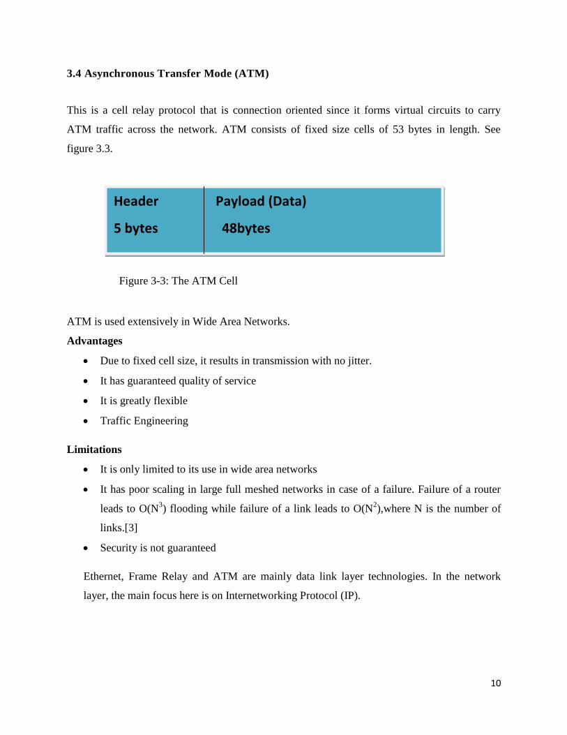
3.4 Asynchronous Transfer Mode (ATM)
This is a cell relay protocol that is connection oriented since it forms virtual circuits to carry
ATM traffic across the network. ATM consists of fixed size cells of 53 bytes in length. See
figure 3.3.
ATM is used extensively in Wide Area Networks.
Advantages
Due to fixed cell size, it results in transmission with no jitter.
It has guaranteed quality of service
It is greatly flexible
Traffic Engineering
Limitations
It is only limited to its use in wide area networks
It has poor scaling in large full meshed networks in case of a failure. Failure of a router
leads to O(N3) flooding while failure of a link leads to O(N
2),where N is the number of
links.[3]
Security is not guaranteed
Ethernet, Frame Relay and ATM are mainly data link layer technologies. In the network
layer, the main focus here is on Internetworking Protocol (IP).
Header Payload (Data)
5 bytes 48bytes
Figure 3-3: The ATM Cell

11
CHAPTER 4: INTERNET PROTOCOL (IP)
4.1 Introduction
IP is a technology that does packet delivery from host to host. IP is a connectionless thus
unreliable datagram protocol. It is known as a best- effort data transfer service because IP
does not provide for error checks. IP does not guarantee transmission of the datagram to the
destination.
The data units in the IP layer are called datagrams. The datagrams constitute a header and a
data segment of variable length. The maximum length of a datagram is 65,535 of which the
header has a maximum of 60 bytes. See figure 4.1. [2]
4.2 IP Version 4
Currently, most networks are using version 4. The Internet address in version 4 is 32 bits in
length. The address space is divided into different classes. There are 5 classes:
Class A
Class B
Class C
Class D
Class E
The address space is 232
.
These classes are illustrated in figure 4.2.
Header Data
Figure 4-1: IP Datagram

12
8 bits 8 bits 8 bits 8 bits
Class A
Class B
Class C
Class D
Class E
Figure 4-2: IP version 4 Classes
The network address is used identify the organization to the rest of the internet while the host
address identifies the individual host.
The classful addressing has many challenges. There is wastage of resources in class A and B.
Limited resources in class C. This led to the development of classless addressing.
4.3 IP Version 6 for Next Generation
In view of the growing and evolving data communication and fast growing internet, IP version 4
has been found to have some deficiencies that include:
Address depletion which may not be permanently solved by subnetting, classless
addressing, or network address translation.
For real-time audio and video transmission, IP version 4 does not provide the required
minimum delay strategies and resource reservation.
IP version 4 does not provide encryption and authentication of data for given
applications.
Thus IP version 6 will eventually replace IP version 4. IP version 6 uses 128 bits as opposed to
the 32 bits of IP version 4. Thus gives guarantee that there cannot be depletion of addresses for
internet users.
Network ID Host ID
Network ID Host ID
Network ID Host ID
Multicast Address
Reserved

13
IP version 5 was not implemented due to extensive changes in the OSI layers and also the
expense that was to be incurred [4].
Generally, IP has the following advantage and limitation:
Advantage
Many technologies can be transported over it.
Disadvantages
It is unreliable since it does not guarantee packet delivery.
Traffic sent over IP follows the primary link which may lead to congestion.
Thus there is an inefficient use resource.
The limitations in IP, ATM, Frame Relay and Ethernet led to the invention of Multi-protocol
Label Switching (MPLS) that aims at reducing limitations of layer 2 and 3 technologies and to
reinforce their capabilities but not to wipe them away. [1]

14
CHAPTER 5: MULTIPROTOCOL LABEL SWITCHING (MPLS)
5.1 Introduction
MPLS is a networking technology that attaches labels to frames and/or packets to forward them
through the network. It is called multiprotocol because it is applied not on one protocol only but
more various protocols. Examples are IPv4,IPv6,IPX,AppleTalk,Any Transport over MPLS
which encompasses any layer 2 protocol such as ATM, Frame Relay, Point-to-point
Protocol(PPP), Fibre Distributed Data Interface (FDDI) .
5.2 MPLS
MPLS is sometimes called layer 2.5 technology as shown in figure 5.1 [1]. MPLS uses label to
label mapping between routers. In layer 3 the labels are attached to IP packets thus the routers
are enabled to forward traffic while looking at the label as opposed to IP forwarding which at
each hop has to look at the destination IP address. Consequently, MPLS utilizes label switching
as opposed to IP routing.
This label switching technique was at first used in Frame Relay that uses frames and ATM that
uses frames called cells to traverse a network. The ATM cell and Frame relay header refer to the
virtual circuit that the given cell or frame, respectively, lies on. In both ATM and Frame Relay
the label value in their header is changed at each hop in the network. This is opposed to IP which
does not change the destination address of datagram. The label switching technique has enabled
MPLS to be one of the most preferred technologies in the networking world.
MPLS has the following capabilities:
It combines the traffic engineering capabilities of ATM with the flexibility of class of
service (CoS) differentiation of IP. Thus a better IP over ATM integration
Ensures that the traffic flow is optimum
Traffic Engineering
MPLS is a standards based technology
MPLS keeps up with growth in the technological world
Increases scalability

15
IP Layer 3 Layer 3
MPLS Layer 2.5
Ethernet, Frame Relay,
Layer 2
ATM, PPP, etc
Physical Layer
From figure 5.1 it is seen that MPLS provides a very useful link between the connection-oriented
switching in layer 2 and totally connectionless routing in layer 3.A more striking example is
ATM and IP.
On that note, the essence of MPLS technology with reference to its benefits is looked at. The
main reason why MPLS was invented was not to increase packet transfer across the network.
5.3 MPLS Creates a Unified All- protocol Infrastructure
After MPLS has labelled an incoming packet as per its destination address, it switches the traffic
over a common infrastructure. IP is known as an all technology network in that apart from
forwarding data it also transports voice and video. That is why IP has gained prominence in the
networking world. The same is to MPLS that gave it the name “Multi-Protocol” meaning it can
transport a labelled packet on any protocol both in layer 2 and layer 3.
Figure 5-1: OSI/MPLS Layer Comparison

16
5.4 MPLS Creates a Better IP/ATM Integration
Due to the outstanding prominence of IP over other layer 3 technologies like IPX, AppleTalk,
DECnet it became a preferred technology in internetworking. This is because of, as stated earlier,
its simplicity and flexibility.
ATM, on the other side, is a well known connection-oriented technology but limited to its being
used as a WAN protocol in layer 2 .Thus arose the need for IP over ATM. Many solutions were
put in place to achieve this. These include:
Multiprotocol Encapsulation over ATM adaptation layer 5 in which ATM circuits are
manually set up and all mappings between IP next hops and ATM endpoints are manually
configured on every ATM-attached router in the network.
LAN Emulation (LANE) –Due to failure of Ethernet to achieve scalability and reliability
as expected LANE was invented as an emulator of an Ethernet network such that various
Ethernet segments were bridged together as if the ATM wide area network in the middle
were an Ethernet switch.
Multiprotocol over ATM (MPOA) which is a complex way of integrating IP over ATM
The three given methods became tedious in implementation and also during troubleshooting.
This led to the invention of MPLS which enables the ATM switches to intelligently run an IP
protocol and implement a label distribution protocol.
5.5 Optimum Traffic Flow
As stated earlier, in ATM and Frame Relay switching there has to be a direct connection through
a virtual circuit between two routers for traffic to be sent across that network. Thus in case of any
to any connection it is tedious to achieve optimum traffic flow due to the full complex mesh of
manually created virtual circuits between two connected sites. Using MPLS VPN, the traffic
flows optimally without full mesh interconnection of virtual circuits.
5.6 Traffic Engineering
Traffic engineering is generally trying to identify the resources available in a given network and
then utilizing them to a maximum in adherence to set standards. In IP routing, the Interior

17
Gateway Protocol (IGP) seeks for a shorter and cheaper route leaving the other routes unused
hence underutilization of resources. Thus traffic engineering is not fully achieved.
A MPLS implemented network, the traffic flow does not necessarily follow the least cost link but
ensures uniform and optimal utilization of resources in a network. This will be discussed in detail
in the following chapters.
5.7 MPLS Terminologies
Multiprotocol Label Switching term can be divided into two parts:
Multiprotocol meaning MPLS works on various protocols as mentioned before.
Label Switching that involves putting labels on information units, packets, whereby these
labelled packets are switched across the network.[3]
5.6.1 MPLS Header
An MPLS header is very important in MPLS implementation. Figure 5.2 shows the constitution
of an MPLS header.

18
5.7.1.1 Label
This constitutes the value of the MPLS label which ranges from 0-1,048,575 with the first 16
values reserved for special purpose.
5.7.1.2 Experimental bits
Used for quality of service thus it affects queuing of packets and discard of algorithms applied
to the packets as they traverse the network.
5.7.1.3 Bottom of Stack
A stack is a collection of labels located on a packet. The bottom of the stack reads 1 if the label is
the bottom one as shown in figure 4.3.This enables it to support hierarchical label stacking.
In MPLS based services, the stacks are given various names depending on where they are
applied. In MPLS VPN label stack, the second label identifies the VPN. In MPLS TE, the top
label shows the ending point of the traffic engineering tunnel while the second label shows the
destination. In Any Transport over MPLS (AToM) and Virtual Private LAN Service (VPLS), the
top label shows the endpoint or tunnel header and the second label shows the Virtual circuit
(VC).
5.7.1.4 Time to Live (TTL)
This is used to prevent a packet from getting stuck in a routing loop. TTL value is decreased by
one as the packet moves from hop to hop. It is also used for path tracing.
Label (20 bits) EXP (3 bits) Stack (1 bit) TTL (8bits)
Figure 5-2: The MPLS Header

19
5.7.2 Label Binding
This is an association of an FEC prefix to a given label so that the receiver knows which label
goes to which packet.
5.7.3 Labelled Packet
This is a packet encoded with a label. A packet with more than one label is called a label stack.
The individual labels on the stack are implemented using Last in-First out (LIFO).
Label Exp. 0 TTL
Label Exp. 0 TTL
Label Exp. 0 TTL
...................................... ............... ................ ..................
………………………... ………… ………..... …………...
…………..................... ………… ………….. ..................
Label Exp. 1 TTL
5.7.4 Label Switch Router (LSR)
This is an MPLS node that receives and transmits labelled packets. It has the capability of
understanding the information on the MPLS label. There are three categories of label switch
routers:
Figure 5-3: MPLS Label Stack

20
Ingress LSR
This type of node receives non-MPLS labelled packets and labels them as they enter the
MPLS network.
Intermediate LSR
This node receives MPLS-labelled packets and switches them within the MPLS network.
Egress LSR
This node receives the MPLS labelled packets, removes the labels then forwards them to
the data link.
The egress LSR and the ingress LSR are referred to as Label Edge Routers (LERs) as shown in
figure 5.4.
Figure 5-4: LSRs and LSPs in a Typical MPLS Network [5]
LSR Operation
An LSR performs three main processes:
Push
21
This is the process of adding labels onto an already created label stack. This type of
router is called an imposing router
Swap
This is the process by which the top label of a received labelled packet is swapped with a
new label then switched to the next LSR.
Pop
This is where one or more labels are removed from the top of the label stack. This type of
router is called a disposing router.
This process is demonstrated in figures 5.5 and 5.6.
5.7.5 Next Hop Label Forwarding Entry (NHLFE)
NHLFE is used by the LSR to forward packets. NHLFE information base at every LSR may
contain all or some of the following:
The address of the next hop
Push, swap and pop operations
The label stack used to switch the data
The data link encapsulation used in packet transfer
Other information required for packet processing
5.7.6 Label Switched Path (LSP)
A series of label switch routers for packet switching in an MPLS network forms a label switched
path. The LSP begins at the ingress LSR through the intermediate LSRs if any then finally to
Egress router as shown in figure 5.4. This is the path which the packets belonging to a given
forward equivalence class follow. An LSP is ordered and unidirectional. [4]

22
5.7.7 Forwarding Equivalence Class (FEC)
An FEC is a group of network layer packets that are forwarded in a similar way. All packets in
this FEC group follow the same path in the network and have equal priority. Some of the criteria
used in classifying FEC classes by the ingress router are as follows:
Packets with the same particular route in the IP routing table
Packets that belong to the same group are multicast
Packets forwarded the same way according to IP differential service code or precedence
Data Link frames in an MPLS network entering the ingress label switch router on one
virtual circuit and on the egress label switch router on one virtual circuit.
Packets with same border gateway protocol prefix and same destination in their IP
addresses.[3]
Figure 5-5: MPLS Basic Operation [5]

23
Figure 5-6: Label Imposition, Swapping, and Deposition
5.7.8 Incoming Label Map (ILM)
ILM information enables a given LSR to choose a set of NHLFEs containing the information for
switching packets. [4]
5.7.9 FEC to NHLFE Map (FTN)
FTN allows LSR to process an incoming unlabeled packet before it is forwarded. FTN also maps
a label to a set of NHLFEs in order to balance the load of packets over multiple paths with equal
costs. [4]
Figures 5.5 and 5.6 show a simple summary of MPLS operation in an IP network with some
terminologies used.
5.7.10 Control Plane
This where routing information and label information are exchanged.

24
5.7.11 Data Plane
This is also called the forwarding plane. After the establishment of the control plane, the data
plane is used to perform the actual forwarding of packets [1].
5.8 Label Distribution
Label Distribution is the process of LSP set up. It involves the insertion of mappings in the
forwarding tables at each LSR. The mapping is from {Incoming interface, Label Value} to
{Outgoing Interface, Label Value}. The first label of a given LSP is imposed on the ingress LSR.
One or more labels can be imposed on the incoming packet. As the packet traverses the MPLS
network the intermediate LSRs only swap the top label, that is, the incoming label on a labelled
packet with another label, the outgoing label. Then the packet is moved to the outgoing link.
Finally, the egress LSR disposes the labels as the packet exits the MPLS network.
5.9 Label Distribution Protocol (LDP)
For label distribution to occur effectively there needs to be coordination between adjacent LSRs.
Since LSRs are not globally known within a network there is need for label distribution protocol.
Label distribution protocol is a set of rules and procedures that enables one LSR to communicate
with its neighbouring peers. This specification is used by an LSR to inform next LSR of an
assigned label and its associated meaning. This exchange of information establishes a mutual
agreement between the LSR pair.
Since MPLS architecture does not have a specific required LDP to be used there are two
categories of LDPs, namely:
Extensions to existing protocols
Developing new protocols

25
5.9.1 Extensions to Existing Protocol
This involves the addition of label distribution information within the existing data flows in the
existing protocols.
Examples are:
Border Gateway Protocol (BGP) extensions: In this case Forward Class Equivalences
(FECs) are used to identify the prefixes distributed by the BGP LSR peers. The use of
same devices has the following advantages:
It eliminates the need for another protocol running on the LSR
Since BGP route reflectors are used in distribution of labels, scalability is enhanced
significantly.
The routing and label distribution are ever in synchrony because the label and the
prefix must coexist.
However, it is not easy to extend the prefixes on the routing protocol to carry the labels.
Resource Reservation Protocol (RSVP) extensions: Here, RSVP standards are enhanced
to include the support for establishing and distributing information for a given LSP. Thus
resources will be allocated along the end to end path. [4].
5.9.2 Developing New Protocols
New protocols for distributing labels are being developed. These protocols are independent of
the existing routing protocols at each hop along the label switched path. This method’s
advantage is that it allows an LSP to traverse LSRs that do not support one of the extended
routing protocols to include label distribution information. Thus the routing protocol distributes
prefixes while the new protocol distributes labels. The main disadvantage is that a new protocol
is required on the LSRs which is an extra task and cost. [4]
5.10 Label Distribution Approaches
There are two categories of the methods used to effect communication between LSRs in an
MPLS Network. These are:
Downstream on Demand

26
This is where the ingress LSR requests for a label binding for a particular FEC from the
next LSR for that given FEC.
Downstream Unsolicited
This is where the egress LSR together with intermediate LSRs distributes label bindings
to LSRs that have not requested for the information.
In both the two approaches, the labels are allocated opposite to the direction of data flow, that is,
from downstream. This is shown in figure 5.7.
Figure 5-7: Label Distribution in an MPLS Network [5]

27
5.11 The MPLS Fundamentals of Forwarding
5.11.1 Frame Mode
Frame mode is used when a packet is forwarded with a label inserted in front of a layer 3 header,
say, IP header.
5.11.2 Cell Mode
Cell mode is used in an ATM LSR network that uses MPLS to exchange Virtual Path Identifier
(VPI) or Virtual Circuit Identifier (VCI) information. For ATM, the label is said to be encoded in
a cell’s VPI/VCI fields. In the control plane the label is exchanged after which in the forwarding
plane the packet is segmented into ATM cells by the ingress Label Edge Router (LER).After this
segmentation the ingress LER forwards the cells. As opposed to the edge ATM, LSRs the
intermediate ATM LSRs act normally as ATM switches. The egress ATM LSR reconstitutes the
cells into a packet.

28
CHAPTER 6: TRAFFIC ENGINEERING WITH MPLS (MPLS TE)
6.1 Introduction
Traffic Engineering is the ability to steer traffic in a network. It is the ability to ascertain the
available resources in a network and being able to utilize them maximally. Since Traffic
Engineering involves moving traffic from end to end in a network, it was only implemented in
ATM and Frame Relay because of their circuit-oriented operation. Due to the prominence of IP’s
flexibility, Frame Relay and ATM were used to steer traffic in IP network. But due to many
networks relying on pure IP network it led to the necessity of introducing MPLS onto the IP
network. Pure IP network does not support Traffic Engineering but IP/MPLS network makes
Traffic Engineering possible due to incorporation of Traffic Engineering with MPLS (MPLS-
TE).
6.2 Traffic Engineering with MPLS (MPLS TE)
IP routing is based only on Interior Gateway Protocol (IGP) metric. This implies that IP routing
will only steer traffic in least cost path. This gives rise to congestion in some paths while others
are underutilized. The congestion leads to dropping of the excess packets due to exhaustion of
bandwidth. But this dropping of packets does not stop the IP routers from forwarding packets in
the congested link.
Due to the changing traffic patterns, addition of bandwidth does not solve the problem. At the
same time it is time consuming to add bandwidth. Thus the only available way to solve this
limitation is by use of MPLS-TE.
MPLS-TE achieves the following objectives:
To ensure efficient spread of traffic within the network thus avoiding overuse of some
links in the network at the expense of other links
To consider the available bandwidth within the network
To acknowledge link attributes such as jitter and delay.
To keep in tune with the changing bandwidth and link attributes
To use explicit routing as opposed to IP’s destination based routing.
The given objectives ensure lower overall cost of operation as well as efficient use of bandwidth
resources [3], [8].
Using a sample simple network, a traffic example can be illustrated as shown in figure 6.1.

29
Figure 6-1: Traffic Engineering in a Sample Network
With reference to figure 6.1, consider traffic engineering with layer 2 ATM or Frame Relay. This
network is also called overlay network as shown in figures 6.2 and 6.3.
Figure 6-2: Traffic Engineering Using Layer 2 (L2) on Layer 3 (L3)

30
Figure 6-3: Traffic Engineering with ATM Switching
As seen earlier, ATM and Frame Relay are used in traffic Engineering as shown in figures 6.2
and 6.3. Permanent Virtual Circuits (PVCs) are formed between switches to steer traffic as in
figure 6.3. But this has the following limitations:
It requires extra devices in the network hence more cost
It increases network complexity hence difficult to manage
For large networks, the full mesh circuits lead to scalability problems
Additional bandwidth required
Traffic engineering with layer is shown in figure 6.4. One path is overused more than the other.
As seen earlier the traffic engineering in an IP network is not fully achievable especially for large
networks and varying traffic. This is because IP uses IGP metric only. On the other hand, it does
not have explicit routing.

31
Figure 6-4: Traffic Engineering with IP
6.3 Traffic Engineering Mechanisms of Operation
The main aim of MPLS TE is to achieve explicit routing, a technique not efficiently achieved by
the most preferred flexible IP. To achieve explicit routing, the following mechanisms are taken
into consideration:
The link constraints which determine how much traffic can be steered on a link and
which traffic tunnel to be used on the link.
Traffic Engineering information distribution. This is achieved by link-state routing
protocols that are MPLS TE enabled ,that is, Open Shortest Path First (OSPF) and
Intermediate-System to Intermediate-System (IS-IS) .When one of the protocols is used
it ensures that the network topology and the available resources are known to the LSRs.

32
A path calculation algorithm used to calculate the best path to be followed from the
ingress LSR to Egress LSR.
Modified Resource Reservation Protocol (RSVP) used as a signal protocol to signal the
traffic engineering tunnel across the network thus setting up the LSPs. Constraint based
by use of Label Distribution Protocol (CR-LDP) is also used to set up the LSPs.
Traffic forwarding method onto the traffic engineering tunnel
The term traffic engineering tunnel refers to data flows between a given specific source and
destination that have attributes associated with them. These attributes include bandwidth
requirements and class of service for the data to be forwarded through the tunnel.
The following is the procedure of setting up the LSP path for MPLS TE:
1. The network operator configures an MPLS TE path on the ingress LSR.
2. The ingress router computes hop to hop route across the MPLS network. Link state
routing protocols OSPF or IS-IS with extensions for TE are used to advertise the
availability of resources on the routers in the network. This facilitates the route
computation.
3. The ingress LSR requests for establishment of LSP using either RSVP or CR-LDP as the
dedicated signalling protocol.
4. The intermediate LSRs along the MPLS TE LSP to be established may either reject or
accept the path request. On acceptance, the internal MPLS switching infrastructure is set
up.
5. The MPLS TE LSP is only operational if and only if all the intermediate LSRs along the
path accept LSP path signalling request.
6. The ingress router can now use the established LSP to handle special data in case of static
routing or seamlessly integrate this new path into the link state routing protocol.
6.3.1 Path Calculation (PCALC)
OSPF or IS-IS are extended to include the information about the link attributes that will be used
for TE. This information when sent by the link state protocol is used to build the TE database.
The MPLS database built is used by path calculation (PCALC) or constrained shortest path first
33
(CSPF) to calculate the shortest path that considers all the network constraints from the ingress
LSR to the egress LSR. The path calculation takes place on the ingress router.
6.3.2 RSVP with TE Extensions (RSVP-TE) Signalling Process
The intermediate LSRs use RSVP-TE as a signalling protocol to know to which LSP the
incoming and outgoing labels belong in a given traffic engineering (TE) tunnel. RSVP operates
in downstream on demand label advertisement mode.
RSVP-TE consists of four extensions as follows:
RSVP Path Message
This is the message sent by the ingress LSR to the egress LSR used to request a label
mapping to the LSP or the TE tunnel
RSVP Reservation Message
This is the message sent from the egress LSR used to allocate labels mapping to the LSP
or TE tunnel and is propagated upstream.
RSVP Error Message
In case the requested resources are not available, the LSR requested will respond by
generating RSVP error messages and sends them upstream to LSR which sent the
request.
RSVP Tear Messages
Two types of tear messages are created by RSVP, that is, PATH tear message and
RESERVATION tear message. The tear messages instantaneously clear the
PATH/RESERVATION states on the router. This enables the reuse of the available
resources on the router through other requests.
RSVP TE operation is shown in figure 6.5.
6.3.2.1 RSVP Objects in the Path Message
SESSION
It defines the source and the destination of the LSP tunnel and is normally identified by IP
addresses of corresponding loopback interfaces on ingress and egress routers.
34
SESSION_ATTRIBUTE
It is used to define the characteristics of the specific LSP tunnel such as the bandwidth
requirements and resources that would need to be allocated to the tunnel.
EXPLICIT_ROUTE OBJECT (ERO)
Populated by the list of next hops that are either manually specified or calculated using
constraint-based shortest path first (CSPF). The previous hop (PHOP) is set to the router's
outgoing interface address. ERO provides the specific path information for the RSVP Path
message to follow.
RECORD_ROUTE OBJECT (RRO)
This is populated with the local router's outgoing interface address in the path of the LSP tunnel.
Thus RRO records the actual route a packet traversed.
SENDER_TEMPLATE
In addition to the previously mentioned attributes, the sender template object in the path message
depicts the interface address that will be used as the LSP-ID for the tunnel. This value is defined
by the ingress router.

35
Figure 6-5: RSVP TE Operation [5]
6.3.2.2 Shared Explicit Style RSVP
This is in TE to ensure that make-before-break is issued. This means that a new TE LSP is built
before the tearing of the old LSP for a given tunnel. The traffic is then set on the new LSP thus
avoiding or reducing traffic loss.

36
6.4 Traffic Engineering Information Distribution
A link state routing protocol is of great importance when it comes to implementing MPLS TE.
The protocol is used to flood the constraints on the network links to all routers running traffic
engineering. Distance routing protocol cannot perform MPLS TE since it only forwards data to
the best route while the consideration for alternate paths is lost. Thus interior gateway protocol
(IGP) is required to be able to flood the state of all links on a router to all the other routers in a
given area so that there can be alternate paths to the destination thus achieving TE.
Apart from the head end router knowing information about all alternate possible paths to the
destination, it needs also to consider the network constraint information. Constraint information
is the collection of all information about resources on links that is necessary to achieve TE. Thus
the need of the link state routing protocol to have extensions that will carry this extra
information. The TE link resources include:
TE metric
Used to construct the TE topology distinct from the IP topology in that it is different
from OSPF cost or IS-IS metric of the link.
Maximum bandwidth
This is the total bandwidth on the link
Maximum reservable bandwidth
This is the available bandwidth that can be used for TE on the link
Unreserved bandwidth
This is the remainder of the bandwidth that is available for TE. It is the difference
between the maximum reservable bandwidth and the bandwidth in use by the TE
tunnels.
6.4.1 OSPF Extensions for TE
OSPF protocol is extended by three opaque link-state advertisements (LSAs) that are used for
addition of MPLS TE information. This enables OSPF to flood information in the whole
network. The three types of LSAs are:
Opaque LSA type 9- This floods information not beyond a local link
Opaque LSA type 10- This floods information area wide

37
Opaque LSA type 11- This floods information autonomous system (AS) wide thus
covering the OSPF domain
MPLS TE uses type 10 LSA for intra-area MPLS-TE.
6.4.2 IS-IS TE Extensions
IS-IS is extended two new type length values (TLVs) that are used to carry the MPLS TE
information.
Extended IS Reachability TLV or Type 22- This describes IS-IS neighbours, the cost to
them and other descriptions.
Extended IP reachability TLV or Type 135- It succeeded the IP reachability TLV type
128 and TLV type 130.
6.4.3 IGP Flooding
The following cases make IGP to flood TE information:
Change in link status
Change in configuration
Periodic flooding
Changes in the reserved bandwidth
In case of tunnel set up failure
6.5 TE Attributes of the Link
These are the characteristics of every MPLS TE enabled link that the ingress router uses to
determine which link a TE tunnel can follow. These include:
Maximum reservable bandwidth
This is the maximum bandwidth reservable which forms a pool that all regular TE tunnels
use.
Attribute flags
These flags show the resources of the link, the capabilities of the link or administrative
policies.

38
TE metric
This is the IGP cost of the link. During the calculation of the path in the network, a tunnel
takes into account the IGP cost of the links.
Shared risk link groups (SRLGs)
This indicates the links that share a common fibre or conduit. In case of the fibre failure,
a group of links are affected hence they share a common risk.
Maximum reservable sub-pool bandwidth
The sub-pool bandwidth is a fraction of the global-pool bandwidth that is used by
DiffServ-aware TE tunnels to obtain their bandwidth
6.6 Attributes of the MPLS TE Tunnels
Tunnel destination
This is the MPLS TE router ID of the egress router that the tunnel LSP should be routed
to.
Desired bandwidth
This is the bandwidth required by the TE tunnel.
Affinity
The affinity bits are used to control whether the tunnel is allowed to cross a certain link
with given attribute flags.
Setup and holding priorities
Re-optimization
Path options
Setup and holding priorities, re-optimization and path options are used in TE tunnel path
calculation.
6.7 Calculation of the TE Tunnel Path
The calculation of a TE tunnel path is dependent on the following factors:
Setup and holding priorities
Re-optimization
Path options

39
Affinity bits and attribute flags
6.7.1 Path Set up Option
The configuration of the path option on the ingress LSR is done in two ways:
Explicitly. This is where every router up to the egress LSR on which the tunnel is routed
is specified. The TE router ID or the link IP address of the intermediate routers is
specified.
Dynamically. This is where the ingress LSR is left to decide which best route the tunnel
should take towards the destination. Thus only the egress ID is configured on the egress
router.
6.7.2 Setup and Holding Priority
In order that more important tunnels are prioritized over the less important ones, setup and
holding priority are used. The setup priority shows how important the tunnel is to pre-empt other
tunnels. The holding priority shows how much the weight of that tunnel is to hold on to
reservations on the links. Thus in case a tunnel has a lower setup priority over a second one, it
can pre-empt that of the second one. This implies that the lower the setup priority and the lower
the holding priority the more important the tunnel.
6.7.3 Re-optimization
A tunnel can be set up on a path that is no longer its optimal path. This occurs when a previously
down link becomes available again or when a link that did not have enough unreserved
bandwidth at the time of tunnel set up but now has enough unreserved bandwidth for the TE
tunnel to be routed across that link.
Re-optimization enables a tunnel to be re-routed in the MPLS TE network onto a more optimal
path. This is accomplished in three ways:
Periodic Re-optimization which occurs at a default frequency of one hour
Event-driven Re-optimization which occurs when a link becomes operational for MPLS
TE but there is no re-optimization.
Manual Re-optimization forces re-optimization for all TE tunnels on ingress router [3].

40
6.8 Forwarding Traffic onto MPLS TE Tunnels
There are six ways to enable the TE tunnel to forward traffic. These are:
Static routing
A static route is configured on the ingress router. The TE tunnel is configured as the
outgoing interface in the static route.
Policy based routing
This is a configured policy that is used on the incoming interface to steer traffic to a
particular next hop
Auto route announce
This is a command configured on the ingress LSR to insert IP destinations into the
routing table with the TE tunnel as the next hop
Forwarding adjacency
Through forwarding adjacency feature, the IGP sees the TE LSP as a link. Any router in
the area running shortest path first (SPF) includes this link.
Direct mapping of AToM traffic onto TE tunnels
Class based tunnel selection

41
CHAPTER 7: CONCLUSIONS AND RECOMMENDATION
7.1 Conclusions
ATM and frame relay are used in networking to achieve traffic engineering. It was realized that
as the network becomes large, ATM and frame relay connections form a complicated full mesh
of virtual circuits that are difficult to troubleshoot in case of link and node failure. This also leads
to poor scalability.
IP is flexible but it has limited traffic engineering capabilities. IP /ATM integration for traffic
engineering becomes complex as the network increases in size. Also, running pure IP is of great
essence in networking.
From the project analysis, it was found that MPLS brings layer 2 switching to layer 3. It also
incorporates connection oriented properties to the connectionless IP.
It was also seen that MPLS TE can be used to build label switched paths with guaranteed
bandwidth. MPLS TE avoids path computation along certain links which have limited
bandwidth. This avoids congestion in those links.
Thus MPLS traffic engineered paths ensure efficient bandwidth utilization. Resource allocation
is also assured in case of resource shortage. MPLS TE also takes control of the path taken by the
traffic in the network.
This reduces the need for extra resources hence lessening the cost of providing service to
consumers.
In Kenya, key entities like Safaricom, Kenya Data Networks are deploying MPLS which has
proved to increase their quality of service provision to their customers at a cheaper cost than
when they were using pure IP.
7.2 Recommendations
The Electrical and Information Engineering department should buy up to date simulation
software like Optimized Network Engineering Tool (OPNET) to aid in simulating sample
MPLS TE networks.
The studied MPLS TE has the following drawbacks:
1. It cannot give bandwidth guarantee on per differential services class basis.

42
2. It is limited to a single autonomous system and interior gateway protocol area.
3. No guarantees are provided for the traffic during failures.
To deal with the given limitations, the developed extensions of MPLS TE should be studied.
These are:
1. Extensions that make MPLS TE aware of Differential services
2. Inter-domain traffic engineering
3. Protection and restoration mechanisms in case of network failure.

43
REFERENCES
1. Eric Osborne, Ajay Simha, Traffic Engineering with MPLS: Design, configure,
and manage MPLS TE to optimise network performance, ©2003 Cisco Systems,
Inc., Printed in the United States of America.
2. Behrouz A. Forouzan, TCP/IP Protocol Suite, Third Edition , ©2006, 2003, 2000
The Mcgraw-Hill Companies, Inc., Printed at Gopaljee Enterprises, Delhi 110
053.
3. Luc De Ghein, MPLS Fundamentals: A Comprehensive Introduction to MPLS
Theory and Practice, ©2007 Cisco Systems Inc., Printed in the United States of
Africa
4. Lydia P., David T B., Chuck D., Jason F., Wei L., Carolyn M., Nicolas R.,TCP/IP
Tutorial and Technical Overview, Eighth Edition, © IBM Corp. 1989-2006,
Printed in the U.S.A.
5. 7750 Service Router, Alcatel-Lucent Service Implementation Course, © Alcatel-
lucent 2007.
6. http://searchtelecom.techtarget.com/tip/MPLS-traffic-engineering-essentials
7. http://www.cisco.com/en/US/dxs/ios/mpls/configuration/guid/mp_link_node_prot
.html
8. Ina Imei, Julian Lucek, MPLS-Enabled Applications: Emerging Developments
and New Technologies , ©2005 John Wiley & Sons Ltd, Printed and bound in
Great Britain by Antony Rowe Ltd, Chippenham, Wiltshire.