Embed Size (px)
Citation preview

UNIVERSITY OF NAIROBI
DEPARTMENT OF ENVIRONMENTAL AND BIOSYSTEMS ENGINEERING
2ND YEAR ELECTRICAL CIRCUIT THEORY LAB MANUAL
Title: NETWORK THEOREMS
Object: To verify some of the network theorems.
Introduction:
Statements of the Theorems to be verified
a) Thevenin’s Theorem
The current in any branch of a network is the same as if the branch was connected to a
generator of e.m.f. Eg and internal impedance Z, where Eg is the potential difference
appearing across the branch when open-circuited and Z is the output impedance of the
network between the branch terminals, all sources of e.m.f. in the network being
replaced by their internal impedances.
b) Delta-Star Transformation
Fig.1: Delta-Star Transformation.
The two networks given in Fig.1 will be identical with respect to terminals L, m and n if
the following equations are satisfied:
Z1 …………… (1)
Z2 …………… (2)
Z3 …………… (3)

c) Reciprocity Theorem
If an e.m.f. Ep in circuit P produces a current IQ in circuit Q, the same e.m.f. Ep in
circuit Q produces the same current IQ in circuit P.
d) Compensation Theorem
For a given set of circuit conditions, any impedance Z in a network carrying a current
I can be replaced in the network by a generator of zero internal impedance and e.m.f.
E - I.Z.
e) Parallel Generator Theorem
The common terminal V of a number generators connected in parallel to a load RL is:
V sc. …………… (4)
Where Isc. Is the sum of the short-circuit currents of the individual generator branches
and Z is the effective parallel impedance of all branches, including the load.
Fig. 2: Circuit of the Parallel Generator Theorem.
f) Norton’s Theorem
If an impedance Z is added to a branch of a network, the resulting branch current I is
given by:
I
Where I, is the branch current before insertion of the added impedance and Zo is the
impedance looking into network from the branch, before insertion of Z

Homework
1. Consider the following circuit:
By using the Thovenin Theorem convert the circuit to the following:
Find VL VNL and Zo as functions of V, R1,R2,R3,R4 and RL then insert the values.
2. When Za = 470Ω, Zb = 330Ω and Zc = 560Ω find from equations 1,2 and 3 the values
for Z1,Z2 and Z3 in the Delta-star transformation.
3. Prove the resiprocity theorem on the circuit shown below:
Find the current I1, interchange the battery and ammeter and find, by calculation, the
new current, I2, through the ammeter. First find the currents, I1, and I2, as functions of
V, R1, R2, R3, R4 and RL, then insert the values for the resistors. Make use of the
results from question 1.

4. In the circuit in question 1 find the battery voltage that will compensate the voltage
drop across RL according to the compensation theorem.
5. From the circuit below find the common terminal voltage V as given in equation. 4, the
parallel generator theorem.
6. Consider the following circuit:
Find the output impedance Zo between A and B. If an ammeter is connected between A and
B find the current Io.
If an ammeter and an impedance Z is connected between A and B find the new current I.
Find the currents and functions of V, RL, R2, R3, R4, and then insert their values.
Check the result with the formula:
I

LAB WORK:
Whenever you change resistance scales on the AVO meter, remember to “zero” the meter
readings.
1. Thevenin’s Theorem.
Connect up the following circuit:
Links between 8 and 9, and 5 and 6.
a) Measure the no load voltage, VNL, between 3 and 6.
b) Connect 2 to 3 and measure VL1.
c) Disconnect RL and the battery V. Measure the output impedance, Zo, when I and 4 are
connected together.
d) Connect up the Thevenin equivalent below:
Set the variable resistor to Zo and measure VL2.
e) How do the values (Zo VL1 and VL2) compare, theoretically and practically?

2. Delta-star transformation
a) Connect up the following circuit:
Links between 8 and 9, 5 and 6 and 2 and 3. Measure the voltages Vln and Vnm.
b) Remove links 8-9, 5-6, 2-3. Connect the star transformation as shown below (values of
Z1, Z2 and Z3 as found in homework):
Measure the voltages Vlm and Vnm. How much do they differ from those found in 2 (a)?

3. Reciprocity Theorm.
a) Connect up the following circuit:
Links between 8 and 9, and 5 and 6. Measure the I1.
b) Interchange the battery and mA meter (battery between 3 and 2, mA meter between 1
and 4) and measure the new current I1 through the mA meter. How much do I1 and I2
differ and why?
4. Compensation Theorem.
a) Connect up the circuit as in 3(a). Measure the current through RL.
b) Remove the mA meter and insert between 3 and 6 (no connection between 2 and 3) a
dc voltage source (E = -II – RL) in series with the mA meter. Be careful with the sign
of E: Measure the new current I2 through the m Ammeter. How much do I1 and I2
differ and why?
5. Parallel Generator Theorem.
a) Connect up the following circuit:
Point 4, 8 and 9 connect with links. Measure the voltage V.
b) Find the short circuit current IscI, of branch 1 (V1 in series with R1), and the short
circuit current, Isc2, of branch 2 (V2 in series with R2).

Disconnect the batteries; connect R1, R2 and RL in parallel and measure the resultant
parallel impedance Z.
Check with the parallel generator formula:
V = (Isc1 1 Isc2).Z
How much do the results from 5a) and b) differ, compare with the homework.
8. Norton’s Theorem.
Connect up the circuit from 3a).
a) Measure the current, II, through the mA meter.
b) Connect a 100Ω resistor in series with the mA meter and measure the new current L.
c) Disconnect the battery, mA meter and 100Ω resistor. Connect the input terminals (1
and 4) together and measure the impedance between 3 and 2, Zo.
d) Check the result with the formula.
I = I1____ and the homework. How do they agree?
1 + Z/ Zo
Apparatus:
1 Power supply.
1 Accumulator, 2V
1 Voltmeter, dc
3 Decade resistor boxes.
1 mA meter, dc.
1 Veroboard “Network Theorems” and box.

UNIVERSITY OF NAIROBI
DEPARTMENT OF ENVIRONMENTAL AND BIOSYSTEMS ENGINEERING
SECOND YEARS: WORKSHOP TECHNOLOGY
DAY 1
Introduction to instruments, identification and inventory
These include,
Ammeters Various transformers
Voltmeters resistance boxes
C.RO’s Capacitance boxes
Power supplies Inductances
Signal generators
The exercise will include how to read the Instruments – ranges, accuracy etc.
DAY 2
Verification for circuit laws, ohms law, kirchoffs law.
Objective:
- To establish the consistence of ohms current, voltage law.
- To establish consistence of Kirchhoff’s node-currents and loop-voltages laws.
- To understand and correct use of ammeters and voltmeters in circuit networks.
RESEARCH (HOME WORK)
NB: It is important you research and finish your homework before coming to do the
experiments in the laboratory.
Assign theoretical but typical values of ammeter internal resistance (RG) and
voltmeter resistance (Rv) using circuits below, investigate to find out which set-up is
more accurate, Explain why.
Now substitute R1, with a very high resistance, say 9000Ω which network is more
accurate. Explain why.
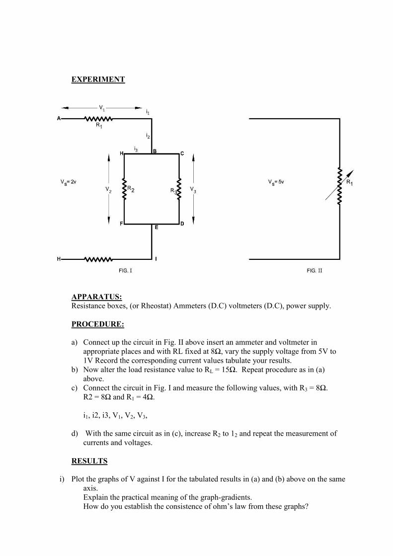
EXPERIMENT
APPARATUS:
Resistance boxes, (or Rheostat) Ammeters (D.C) voltmeters (D.C), power supply.
PROCEDURE:
a) Connect up the circuit in Fig. II above insert an ammeter and voltmeter in
appropriate places and with RL fixed at 8Ω, vary the supply voltage from 5V to
1V Record the corresponding current values tabulate your results.
b) Now alter the load resistance value to RL = 15Ω. Repeat procedure as in (a)
above.
c) Connect the circuit in Fig. I and measure the following values, with R3 = 8Ω.
R2 = 8Ω and R1 = 4Ω.
i1, i2, i3, V1, V2, V3,
d) With the same circuit as in (c), increase R2 to 12 and repeat the measurement of
currents and voltages.
RESULTS
i) Plot the graphs of V against I for the tabulated results in (a) and (b) above on the same
axis.
Explain the practical meaning of the graph-gradients.
How do you establish the consistence of ohm’s law from these graphs?

ii) Find the algebraic sum of currents at nodes B and E in fig. I for both procedures (c)
and (b). Also find the algebraic sum of voltages in the following loops.
ABGFEHA, ABCDEHA and BCDEFGB (Fig. I)
CONCLUSION
Suggest possible causes of error in the circuit measurements in figs. I and II.
Given resistance values as in procedure a, b, c, d and the supply voltages values,
calculate the theoretical values of currents i1, i2, i3 and voltages V1, V2, V3, for fig. I.
Calculate V and I values for fig. II. Compare these values with the practical values
obtained to justify the causes of error suggested above.
DAY 3
CRO 1
Objectives:-
1. To understand the operating of a CRO.
2. To identify all the terminals and controls of the CRO.
3. To investigate the functions of the controls.
4. To derive a systematic “SETTING UP PROCEDURE” to test the functioning of the
instrument.
Research
Explain the primary use of the CRO.
Draw a functional diagram of a basic CRO and indicate the positions of important controls
associated with the instrument function. Give a brief description of the different functional
units associated with the CRO, and the role of the controls of each unit.
Experiment
Identify the CALIBRATION voltage source on the instrument. It is normally specified as:
1.0 volts peak to peak or
0.5 volts peat to peak
the period of the waveform is 20 millisecs. Using this voltage as the INPUT to the Y axis
deflection and by suitable setting of the TIMEBASE and TRIGGERING controls obtain a
suitable display on the screen to give a stationery display of three cycles of the waveform.
Moving each control one at a time investigate carefully the effect of the control on the screen
trace and thus identify controls associate with:
Beam production,
Deflection in the Y axis,
Deflection in the X axis,
Timebase controls
Triggering
Investigate the effects of all the controls in a systematic manner under the groupings,
remembering to return the screen to the original condition each time.

Results:
Indicate a logical “SETTING UP PROCEDURE” to test the servisibility of the CRO
indicating the settings of the controls in the following groups:-
1. Beam location.
2. Fine adjustments of the beam.
3. Location of y-axis 3(a) Scale setting
4. Location of x-axis 4(a) Scale setting
5. Time-base setting.
6. Triggering to the calibration voltage on the input.
Conclusion
Comment on the advantages and disadvantages of the instrument.