Embed Size (px)
Citation preview
AOA9359DETERMINING FIN AZIMUTH WITH A GYROTNEOOOLITE(U) ARMY /ENGINEER TOPOGRAPHIC LAOS FORT BELVOIR VA - K P LOGAN
OCT 86 ETL-9440UNLSIFIlhhhhh0/5 hl

1.0 kW EM W
a.0
11.25 Els4 .6
MIGROC' Pv RtSMtUTIoN TEST GNARl
* DIA hJU 8JkA& AURU;S
S V 5 ' .5 5 5* -
.'' w' :r
ifcEILE Cue~00,. ETL-C0440
'idW-t
00
Determining an azimuth: with a gyrotheodolite
DTICELLECTEI!I
Kevin P Logan S AUG 06 1870
October 1986
APPROVED FOR PUBLIC RELEASE; DISTRIBUTION IS UNLIMITED
Prepared for
U.S. ARMY CORPFOF ENGINEERSENGINEER TOPOGRAPHIC LABORATORIESFORT BELVOIR, VIRGINIA 22060-5546
/: : -e: ; e : : : .. ....... ... .. . .,..,.,..,..............-.... -... -... '-- ,. ...... .,

Destroy this report when no longer needed.Do not return it to the originator.
The findings in this report are not to be construed as an officialDepartment of the Army position unless so designated by otherauthorized documents.
The citation in this report of trade names of commiercially availableproducts does not constitute official endorsement or approval of the
use of such products.
%%
#-
% %
5* ** / 9 ~ -- -~ . - . * -. -. 5- -*-
UNCLASSIFIEDSECURITY CLASSIFICATION OF THIS PAGE (W?,n Date Fntered)
REPORT DOCUMENTATION PAGE READ INSTRUCTIONSi. REPORT NUMBER 2. GOVT ACCESSION NO. RECIPIENT'S CATALOG NUMBER
ETL-0440 B" O"E COMPLETING FORM
4. TITLE (ad Subtiltej 5 TYPE OF REPORT & PERIOD COVERED
DETERMINING AN AZIMUTH WITH A GYROTHEODOLITE Technical Report6 PERFORMING ORG. REPORT NUMBER
7. AUTHOR(*) S. CONTRACT OR GRANT NUMBER,.,,
Kevin P. Logan
9. PERFORMING ORGANIZATION NAME AND ADDRESS 10. PROGRAM ELEMENT. PROJECT, TASKAREA A WORK UNIT NUMBERS
U.S. Army Engineer Topographic Laboratories Surveying and MappingFort Belvoir, Virginia 22060-5546 Work Unit 361-31748
11. CONTROLLING OFFICE NAME AND ADDRESS 12. REPORT DATE
October 1986U.S. Army Engineer Topographic Laboratories 13. NUMBER OF PAGES
Fort Belvoir, Virginia 22060-5546 1814. MONITORING AGENCY NAME & ADDRESS(If different from Controlllng Office) 15. SECURITY CLASS. (of this report)
Unclassified
IS&. DECLASSIFICATION DOWNGRADINGSCHEDULE
16. DISTRIBUTION STATEMENT (of this Report)
Approved for public release; distribution is unlimited.
17. DISTRIBUTION STATEMENT (of the ebetract entered in Block 20, If different fro Report)
18. SUPPLEMENTARY NOTES
%L19. KEY WORDS (Continue on reveree side If necessay atd identify by block number)
CYROTHEODOLITEWILD GAKI
AZIMUTH DETERMINATION
SURVEY PROCEDURES
20. ABSTRACT rco lmuf e re, ree les, si nci't e c" 7 nod Identlfy by block -umbeO
This report is intended as a practical guide to survevors for makingmeasurements to determine an azimuth using a gv rot heodol ite. This report o.ivesa bried description of how the gyro works, improved ohserving, procedures for "its use, and the results of field oh.ervat ions. Accurjwices of + 5 arc secondscan he obtained. .. r
DO I FJOAM 1473 EDITION OF I NOV S15 OBSOLETE CIssi V It'll
SECURITY CLASSIFIC ATION OF THIS PA .F PWlen Pet E'ntFrr,)
, ., [ _' ,','' , .,_.'..•.,, ,'...,..... .... ,........... ... -..-.
SECURITY CLASSIICATION OF THIS PAG9(WhQ i Dlts Eigitm
%.P pp
.P a
-
N
-'4' *d.,.* , %.
-." .'."S
;%P'% %,
SECURITY CLASSIFIC ATI )N 11 ~ A fI4'.' flora f
%%
%,%" %. * I
,del= . . . 4.% . . % . , 4 . , . % ,,.'.., .. ,-..., ..-.:.., .', .... .. -...... .. ...- -. ...- '.. -... .. -.: ': ,'. :-'-, ,.-',-,'-,-,: -'-.,",'- .'', ,- -=,':'%'

PREFACE
The effort covered by this report was conducted under the Civil WorksSurveying and Mapping R&D Program, Work Unit 361-317L48, "Use of ModernTechnology for Survey."
This work was performed under the supervision of Mr. Peter J. CervarichII, Chief, Precise Survey Branch; Mr. John G. Armiistead, Chief, SurveyingDivision; and Mr. Eugene P. Griffin, Director, Topographic DevelopmentsLaboratory.
The author also would like to acknowledge initial efforts by Mr. KennethD). Robertson who started this project and worked on it until his retirement.his input and guidance were deeply appreciated and will be missed on futureprojects.
The author would also like to acknowledge the effcrts of Mr. Jimmy Beeves,Chief, Survey Branch, Mobile District, Corps of Engineers, and his personnelfor their cooperation in using the gyro in their normal field activities andfor supplying data for evaluation. A
Colonel Alan L. Laubscher, CE, was Commander and Director, and Mr. WalterL. Boge was Technical Director of the Engineer Topographic Laboratories duringthe report preparation.
% .
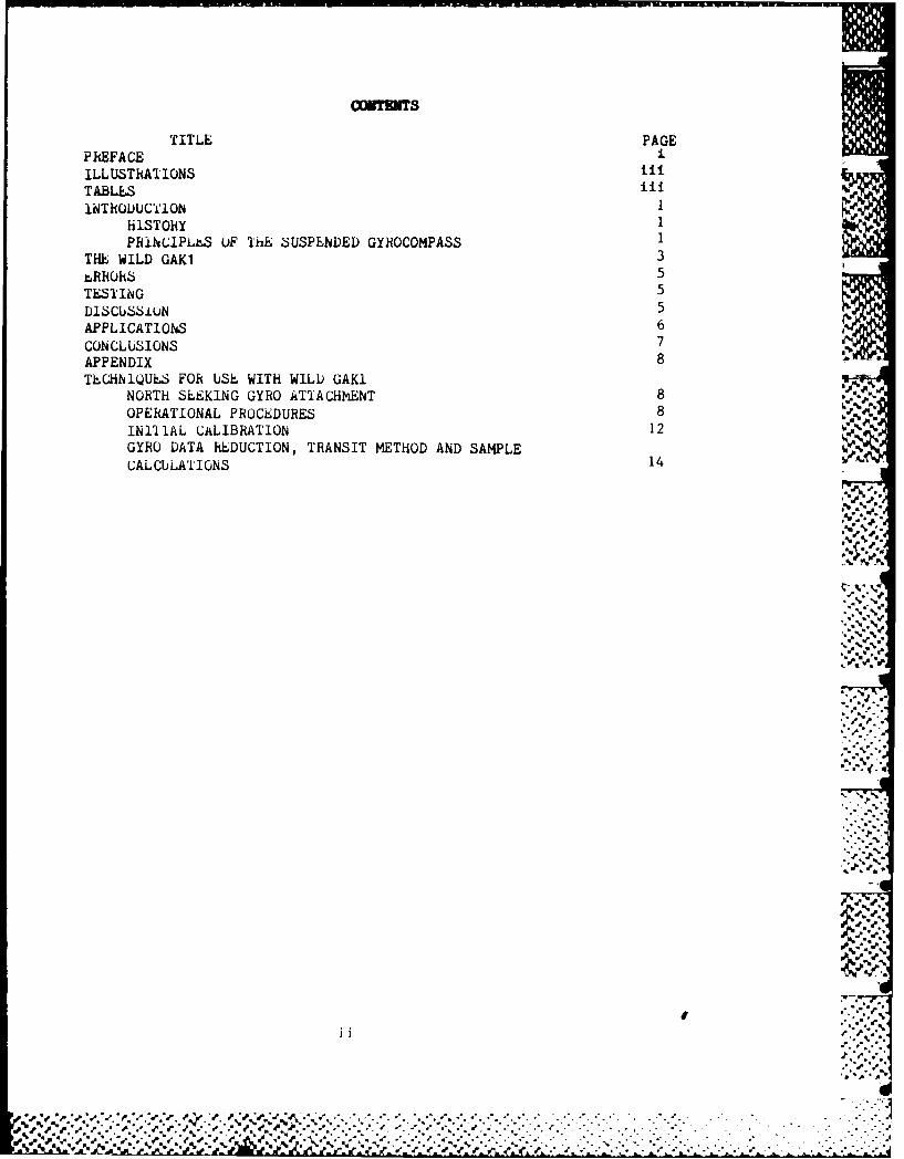
CONTENTS
TITLE PAGEP REFA CE -ILLUSTRATIONS liiTABLES ili iINThODUCTI1ON I "
HiSTORY 1PRINCIPLL.S UF ThE ,SUSPENDED GYROCOMPASS 1
THE WILD GAKI 3
rRRORS 5
TESTING 5
D1SCUSSiUN 5APPLICATIONS 6
CONCLUSIONS 7APPENDIX 8
TLCHNIQUES FOR USE WITH WILD GAKINORTH SEEKING GYRO ATTACHMENT 8OPERATIONAL PROCEDURES 8INITIAL CALIBRATION 12GYRO DATA REDUCTION, TRANSIT METHOD AND SAMPLECALCULATIONS 14
• , .*-
p, e
.- %
'%' '_%
1%..",0
' ,::; .-:]
*.,. *.'. .- ' 0,
",', ~~~~00 ","'"," . ." ,,." -:. . . -. . -. . .'.. . . -. . ... -. . -[i.7

=LLUSTRATIOS
FIGURE TITLE PAGE
I Suspended Uyro 2
2 GAKi Suspended Gyro 4
TABLES
NUMBER TITLE PAGE%. .1 ,-'
1 Azimuth Comparisons 6
2 Observation Field Notes,West Set of Observations 12
3 Observation Field Notes, 13East Set of Observations
4 Observation Field Notes 15
Accesion For -
NTIS CR &IDTIC TAB [1Unainotwnind ,Ju st~fcatio,''"'
e... ... ... .. ..... . . .{ ,i
Oit ,c 1;"
-. #
T
iii ..-,. ,
%.. /*
--%;'-
" ' . " -. ,, '_,'. ," ," .." .' -.,,- . .. . ./ . . .- .., . ."- " " -' - . . ,- ' - ., .. " , .- .- .- -, e • • .' .'%%
DETEIWIN lG AN AZIMUTH WITH A GYROTHEODOLITE
INTRODUCTION
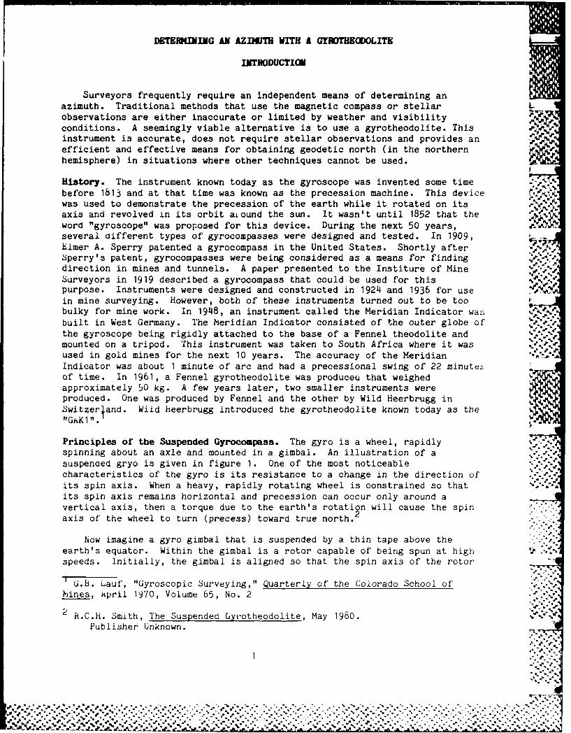
Surveyors frequently require an independent means of determining anazimuth. Traditional methods that use the magnetic compass or stellar Lobservations are either inaccurate or limited by weather and visibility ,R .conditions. A seemingly viable alternative is to use a gyrotheodolite. This P. ,instrument is accurate, does not require stellar observations and provides an
41,- 0
efficient and effective means for obtaining geodetic north (in the northernhemisphere) in situations where other techniques cannot be used.
History. The instrument known today as the gyroscope was invented some timebefore 1813 and at that time was known as the precession machine. This devicewas used to demonstrate the precession of the earth while it rotated on itsaxis and revolved in its orbit ai ound the sun. It wasn't until 1852 that theword "gyroscope" was proposed for this device. During the next 50 years,several different types of gyrocompasses were designed and tested. In 1909, U..
Elmer A. Sperry patented a gyrocompass in the United States. Shortly after . . -Sperry's patent, gyrocompasses were being considered as a means for findingdirection in mines and tunnels. A paper presented to the Institure of Mine .Surveyors in 1919 described a gyrocompass that could be used for thispurpose. Instruments were designed and constructed in 1924 and 1936 for usein mine surveying. However, both of these instruments turned out to be toobulky for mine work. In 1948, an instrument called the Meridian Indicator was .. -
built in West Germany. The Meridian Indicator consisted of the outer globe ofthe gyroscope being rigidly attached to the base of a Fennel theodolite andmounted on a tripod. This instrument was taken to South Africa where it wasused in gold mines for the next 10 years. The accuracy of the Meridian -.- '
Indicator was about 1 minute of arc and had a precessional swing of 22 minute-of time. In 1961, a Fennel gyrotheodolite was produce6 that weighedapproximately 50 kg. A few years later, two smaller instruments wereproduced. One was produced by Fennel and the other by Wild Heerbrugg inSwitzerjand. Wild heerbrugg introduced the gyrotheodolite known today as the
Principles of the Suspended Gyrocompass. The gyro is a wheel, rapidly . -spinning about an axle and mounted in a gimbal. An illustration of a -. .suspenoed gryo is given in figure 1. One of the most noticeablecharacteristics of the gyro is its resistance to a change in the direction of'its spin axis. When a heavy, rapidly rotating wheel is constrained so thatits spin axis remains horizontal and precession can occur only around avertical axis, then a torque due to the earth's rotation will cause the spinaxis of the wheel to turn (precess) toward true north.2
Now imagine a gyro gimbal that is suspended by a thin tape above theearth's equator. Within the gimbal is a rotor capable of being spun at highspeeds. Initially, the gimbal is aligned so that the spin axis of the rotor
G.b. Lauf, "Gyroscopic Surveying," Quarterly of the Colorado School of'hines, April 1970, Volume 65, No. 2
2 R.C.H. Smith, The Suspended Gyiotheodolite, May 1980. "Publisher Unknown.
%.
,# .= •- .,, • J'.-.. -. . . .,-..... . . . -. .. ....... -. . .... *.%... .. .. ..
i , ,-.% %., " ,% % 1',,_.-,. ._• . ...... ...'__ ._..,,, %•,,,.'-,. . . ,,-. *,-•"-. - .- "% ",, . 5 ,
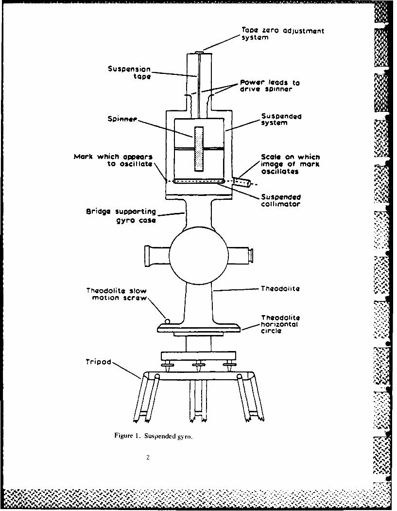
Tape zero adjustmentsystem
S us pensioanop aPower leads to
drive spinner
Suspended
Mark which appears Scale on whichto oscillate image of mark
oscillates
Suspendedcollimator
Bridge supporting___,r,.gyro case
' -. 4.
Theodolite slow Theodolit-motion screw
T heodolitehorizontal
Tripod
Figure 1. Suspended gyro.
2

is pointing in an east-west direction. Now, the rotor is spun so that thesystem becomes a gyroscope. Then, as the earth rotates, the rotor axis will,in effect, be tilted downward with respect to outer space. The gyroscopereacts to the motion by rotating (precessing) about the axis of the suspendingtape.
The rest position for this configuration occurs when the gyroscope isaligned with its axis of spin in a meridian plane. In this orientation thegyro will be translated by the earth's rotation but will not experience anangular change i.e., the spin axis will not be tilted by the earth'srotation. If the gyro is suspended above one of the earth's poles, the spinaxis will always be aligned with one of the meridians, and no tilt of the spinaxis can occur. Consequently, the gyro is at a rest position. At a pointbetween the pole and equator, the gyro will seek to point north, with theprecessing force a function of the latitude.
If the gyro is pointed in a nearly north direction, it will swing(precess) towards north. As it passes north, the force will changedirection. However, by this time rotational inertia about the suspension tapeaxis will force the gyro to swing past the rest point. Thus, the gyro willswing back and forth in simple harmonic motion with both the torsion in thesuspension tape and the precession force causing the swings. At a point nearthe center of the motion lies true north. Using an optical lever techniquesimilar to that of an old fashioned galvanometer, measurements are made of theamplitude of swings on either side of the zero mark of the reticle scale, andthe time is noted when the gyro mark (crosshair) swings
past the zero mark. A ,
brief set of calculations will yield a correction to the theodolite platereading to obtain the direction of true north.
The WILD GAKI. The WILD GAKI gyro attachment is a small gyro that may befitted to a T2 or T16 theodolite to locate the direction of true (astronomic)north or south when the equipment is used in the respective hemispheres (Seefig. 2). Although this attachment has been available for over 10 years, ithas found limited use, possibly because of the high price and an accuracy thathas been limited to about 30 arc seconds. The price of the instrument is stillhigh, but the addition of a vernier modification developed by the UnitedKingdom Royal School of Mines has increased the accuracy to approximately + 5arc seconds. The usefulness of the instrument at that level of accuracy makesit worth the price.
* ..- ."
3
- 9v..;
%.~.- ** % . OP. . / .
% %.V -
0 %L

I Suspension Tape
oJI Gyro
V , .......
Clamping Knob
Figure 2. Cross-section of CAK1 gyro.
- P*~.% %
71JEWROM M N mwbn MEW V~m Pon W1JrJPWP41
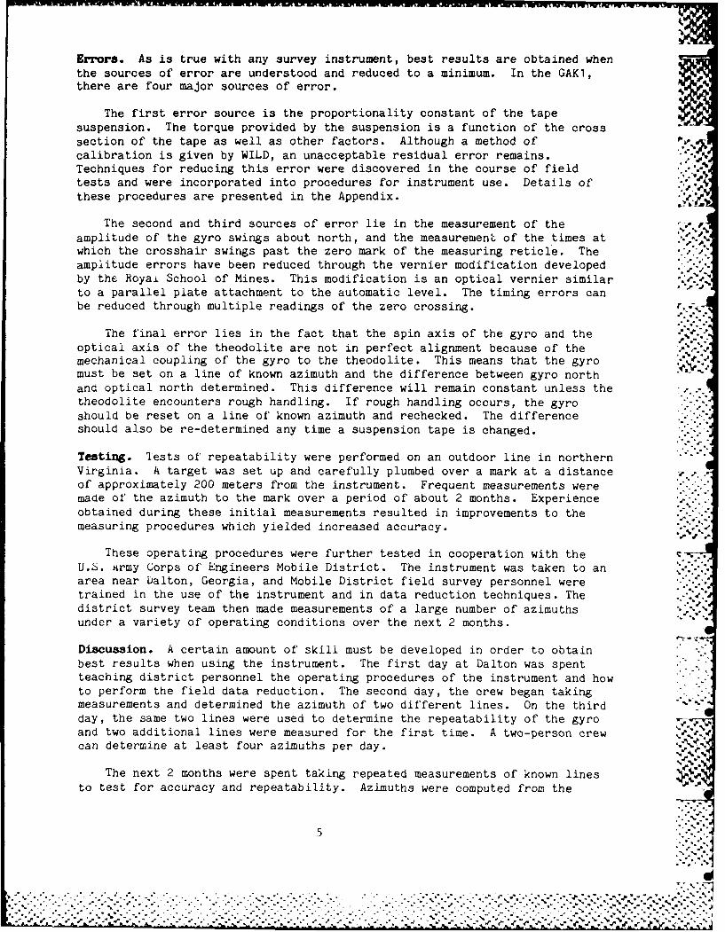
Errors. As is true with any survey instrument, best results are obtained whenthe sources of error are understood and reduced to a minimum. In the GAK1,there are four major sources of error.
The first error source is the proportionality constant of the tapesuspension. The torque provided by the suspension is a function of the crosssection of the tape as well as other factors. Although a method of '.
calibration is given by WILD, an unacceptable residual error remains.Techniques for reducing this error were discovered in the course of fieldtests and were incorporated into procedures for instrument use. Details ofthese procedures are presented in the Appendix.
The second and third sources of error lie in the measurement of the .. ,.
amplitude of the gyro swings about north, and the measurement of the times atwhich the crosshair swings past the zero mark of the measuring reticle. Theamplitude errors have been reduced through the vernier modification developedby the Royai School of Mines. This modification is an optical vernier similar .,
to a parallel plate attachment to the automatic level. The timing errors canbe reduced through multiple readings of the zero crossing.
The final error lies in the fact that the spin axis of the gyro and theoptical axis of the theodolite are not in perfect alignment because of themechanical coupling of the gyro to the theodolite. This means that the gyromust be set on a line of known azimuth and the difference between gyro northand optical north determined. This difference will remain constant unless thetheodolite encounters rough handling. If rough handling occurs, the gyroshould be reset on a line of known azimuth and rechecked. The differenceshould also be re-determined any time a suspension tape is changed.
Testing. Tests of' repeatability were performed on an outdoor line in northernVirginia. A target was set up and carefully plumbed over a mark at a distanceof approximately 200 meters from the instrument. Frequent measurements weremade of' the azimuth to the mark over a period of about 2 months. Experienceobtained during these initial measurements resulted in improvements to themeasuring procedures which yielded increased accuracy. .-
These operating procedures were further tested in cooperation with theU.6. Army Corps of Engineers Mobile District. The instrument was taken to anarea near Dalton, Georgia, and Mobile District field survey personnel weretrained in the use of the instrument and in data reduction techniques. Thedistrict survey team then made measurements of a large number of azimuthsunder a variety of operating conditions over the next 2 months.
Discussion. A certain amount of skill must be developed in order to obtainbest results when using the instrument. The first day at Dalton was spentteaching district personnel the operating procedures of the instrument and howto perform the field data reduction. The second day, the crew began takingmeasurements and determined the azimuth of two different lines. On the thirdday, the same two lines were used to determine the repeatability of the gyro .
and two additional lines were measured for the first time. A two-person crewcan determine at least four azimuths per day.
The next 2 months were spent taking repeated measurements of known linesto test for accuracy and repeatability. Azimuths were computed from the
% .
5
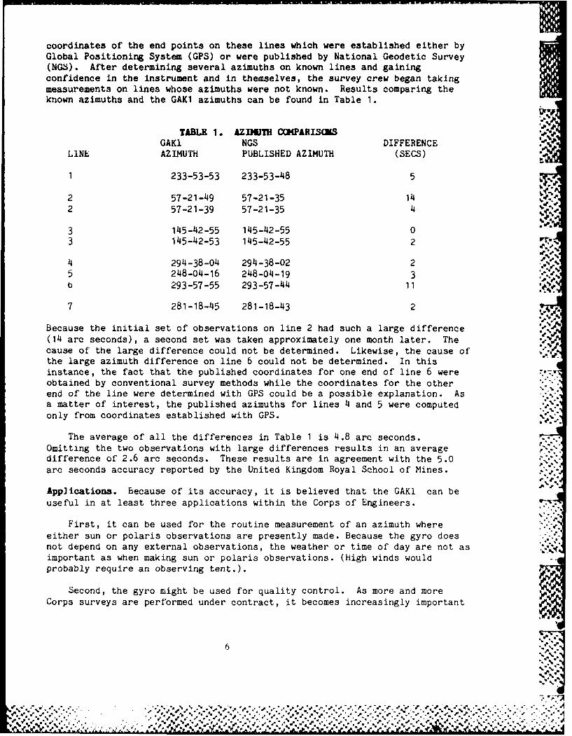
coordinates of' the end points on these lines which were established either byGlobal Positioning System (GPS) or were published by National Geodetic Survey(NGS). After determining several azimuths on known lines and gainingconfidence in the instrument and in themselves, the survey crew began takingmeasurements on lines whose azimuths were not known. Results comparing theknown azimuths and the GAK1 azimuths can be found in Table 1.
TABLE 1.* AZINM COMPARISONSGAKi NGS DIFFERENCE
LINE AZIMUTH PUBLISHED AZIMUTH (SECS)
1 233-53-53 233-53-48 5
2 57-1-49 57-2135 1
2 57-21-39 57-21-35 14
2 15-2-9 15-2-5 0
3 145-42-55 145-42-55 0 T
4 294-38-04 294-38-02 2%5 248-04-16 248-04-19 3b 293-57 -55 293-57-44 11
7 281-18-45 281-18-43 2
Because the initial set of observations on line 2 had such a large difference(14 arc seconds), a second set was taken approximately one month later. Thecause of the large difference could not be determined. Likewise, the cause ofthe large azimuth difference on line 6 could not be determined. In thisinstance, the fact that the published coordinates for one end of line 6 wereobtained by conventional survey methods while the coordinates for the other *
end of the line were determined with GPS could be a possible explanation. Asa matter of interest, the published azimuths for lines 4 and 5 were computedonly from coordinates established with GPS. .
The average of all the differences in Table 1 is 4.8 arc seconds.Omitting the two observations with large differences results in an averagedifference of 2.6 arc seconds. These results are in agreement with the 5.0arc seconds accuracy reported by the United Kingdom Royal School of Mines.
Applications. because of its accuracy, it is believed that the GAKi can beuseful in at least three applications within the Corps of Engineers.
First, it can be used for the routine measurement of an azimuth whereeither sun or polaris observations are presently made. Because the gyro doesnot depend on any external observations, the weather or time of day are not asimportant as when making sun or polaris observations. (high winds wouldprobably require an observing tent.).
Second, the gyro might be used for quality control. As more and moreCorps surveys are performed under contract, it becomes increasingly important
6
-% ,* *.1Z
to develop techniques for checking the contractor's work. The GAKI may beused anywhere in a traverse to determine an azimuth, which can then becompared with results supplied by a contractor.
Third, use of the Global Positioning System (GPS) is increasing because of
its high accuracy and general usefulness. A single measurement with GPSproduces first-order or second-order coordinates for a selected point relativeto a known station, but does not produce an azimuth unless a third,intervisible, point is also measured. The gyro may be used to establish an
azimuth while the GPS measurement of coordinates is being made. This might bedone by setting up on the azimuth mark and measuring the azimuth back to theGPS antenna.
I % -
Many experimental observations have been made with the WILD GAKI to
determine operating procedures that would give the best answers possible. "'.DuringE the course of these tests, techniques were refined to produce the ,
highest accuracy commensurate with practical field usage. These experiments . .
have been confirmed by a survey party from the Mobile District along with
actual field measurements made by ETL personnel. From the results of these -
experiments and field tests, it is believed that by carefully following the :
procedures provided in this report, the GAKI is capable of accuracies on the ".
order of +5 arc seconds•..'.-.
-:.,.% ..
This accuracy, plus the autonomous operating capability of the GAKI, make ...
it a usefui tool for many survey applications such as:
• . * F
Mn heplacing sun or star observations, especially in conditions of poorto .. :
visibility. ..
2. Providing quality control of survey networks. d o t
3. Providing azimuths for surveys established with the Giobal Positioning
System (G) .m empr ltth
100- 1%'.
e i ai %. tproedre pioa s
, . . .. . . . . o . , o o"
". " . ° -" " -° °This.- -acurcy°pu te°utn mu operating- capability". ". of the-. GA1 make- •° --

APPENDIX
TECHNIQUES FOR USE WITH THE WILD GAIKI"NORTH-SEEKING GYRO ATTACHENT
A set of observations with the GAKi may be made in about 1 hour and, whentaken with care, is capable of providing results with an accuracy of +5seconds of arc. For a good instrument operator with theodolite experience,one or two day's training and a week's practice will be sufficient to producea good gyro operator, as the same skills and care apply to the operation ofeither instrument.
0* CAUTION *
The gyro must be in the clamped (caged) position except when finalreadings are being taken. The operator should read these instructions and theWILD operating manual before attempting to use the gyro.
0*0 CAUTION 0#0
OPERATING PROCEDURES
The following operating procedures are simple extensions of the techniquesdescribed in the WILD operating manual for the GAKi gyro. It is assumed thatthe reader is familiar with start up and basic operation of the instrument.
Set Up: With the aid of a compass or some other means, place the tripodover the mark so that one leg is pointing in the direction of north. Thiswill later permit small adjustments of leveling in the east-west direction.Make certain that the tripod is firmly set in the ground. All precautionsshould be taken to insure absolute stability of the tripod during theapproximately 1 hour duration of the measurements. The use of an umbrella isadvised, even on hazy days.
Place the theodolite in the tripod, plumb, and adjust for a coarselevel. Now mount the gyro to the bridge of the theodolite.
*"CAUTION go
DO NOI OVER TIGHTEN THE ALUMINUM MOUNTING RING, AS IT MAY DISTORT AND CHANGEThE CALlbRATION CONSTANT OF THE INSTRUMENT.
0*~ CAUTION 000
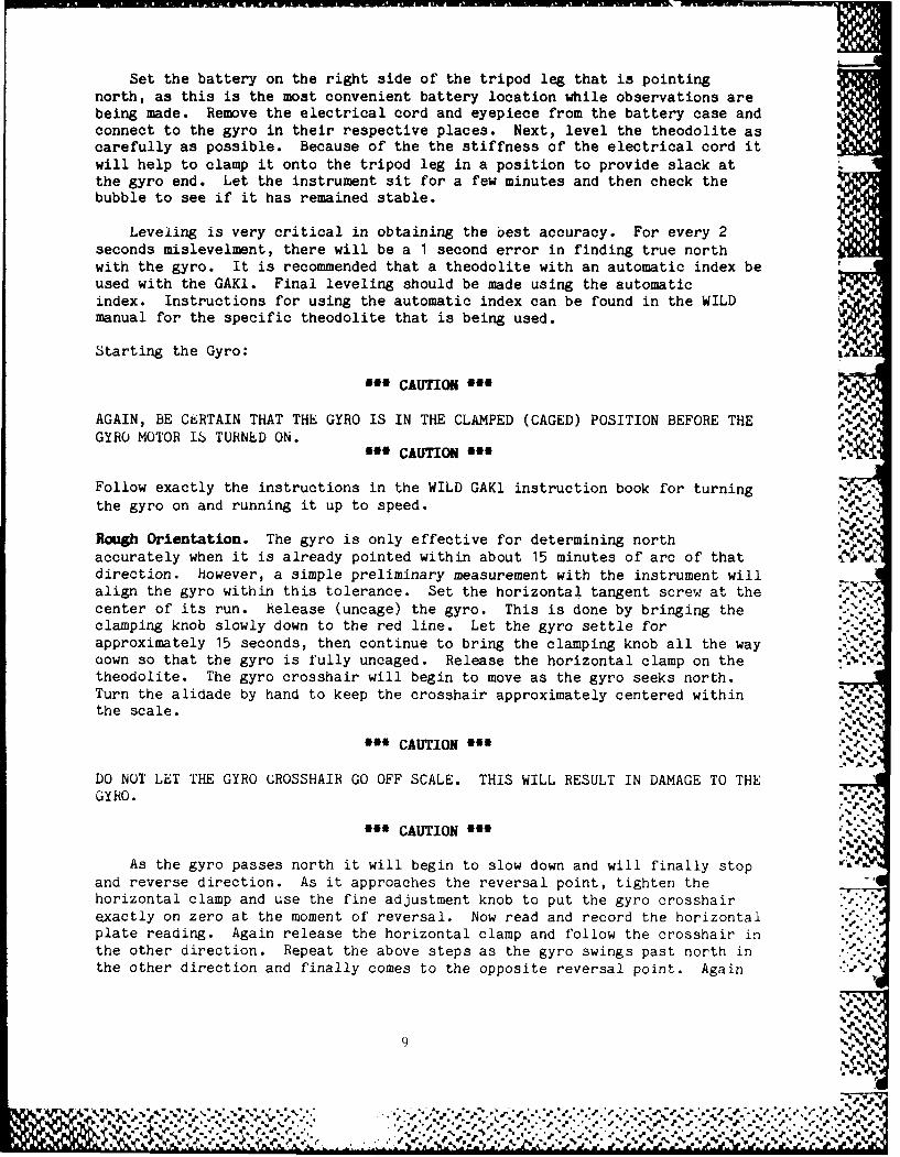
Set the battery on the right side of the tripod leg that is pointingnorth, as this is the most convenient battery location while observations arebeing made. Remove the electrical cord and eyepiece from the battery case andconnect to the gyro in their respective places. Next, level the theodolite ascarefully as possible. Because of the the stiffness of the electrical cord itwill help to clamp it onto the tripod leg in a position to provide slack atthe gyro end. Let the instrument sit for a few minutes and then check thebubble to see if it has remained stable.
Leveling is very critical in obtaining the oest accuracy. For every 2seconds mislevelment, there will be a 1 second error in finding true northwith the gyro. It is recommended that a theodolite with an automatic index beused with the GAKI. Final leveling should be made using the automaticindex. Instructions for using the automatic index can be found in the WILDmanual for the specific theodolite that is being used.
Starting the Gyro: '
900 CAUTION Off
AGAIN, BE C6RTAIN THAT THE GYRO IS IN THE CLAMPED (CAGED) POSITION BEFORE THE 91GYRO MOTOR I6 TURNED ON. l
*** CAUTION *00
Follow exactly the instructions in the WILD GAKI instruction book for turningthe gyro on and running it up to speed.
Rough Orientation. The gyro is only effective for determining northaccurately when it is already pointed within about 15 minutes of arc of thatdirection. however, a simple preliminary measurement with the instrument willalign the gyro within this tolerance. Set the horizontal tangent screw at the .\.center of its run. helease (uncage) the gyro. This is done by bringing theclamping knob slowly down to the red line. Let the gyro settle for .. .-approximately 15 seconds, then continue to bring the clamping knob all the wayaown so that the gyro is fully uncaged. Release the horizontal clamp on thetheodolite. The gyro crosshair will begin to move as the gyro seeks north.Turn the alidade by hand to keep the crosshair approximately centered within .the scale.
*" CAUTION '
DO NOT LET THE GYRO CROSSHAIR GO OFF SCALE. THIS WILL RESULT IN DAMAGE TO THEGYRO.
£a CAUTION
As the gyro passes north it will begin to slow down and will finally stopand reverse direction. As it approaches the reversal point, tighten thehorizontal clamp and use the fine adjustment knob to put the gyro crosshairexactly on zero at the moment of reversal. Now read and record the horizontalplate reading. Again release the horizontal clamp and follow the crosshair inthe other direction. Repeat the above steps as the gyro swings past north inthe other direction and finally comes to the opposite reversal point. Again " I
9 %

read and record the horizontal plate reading. CLAMP (CAGE) THE GYRO byturning the clamping knob gently back up to the red line, letting the gyrosettle for approximately 15 seconds and then gently finish turning up theclamping knob until the gyro is fully caged. Determine the mean of the twohorizontal plate readings. This value is the approximate direction of north.
Example:
Horizontal Plate Reading #1= 18-01-41Horizontal Plate Reading #2= 46-15-25
Mean Plate Reading = 32-08-33
Reset the horizontal plate angle to the mean angle that was obtained fromperforming the rough orientation. This is the angle that the first correctionwill either be added to or subtracted from to get true north.
Final Readings. There are two methods of making the final readings todetermine true north. One is the reversal method and the other, the transit 7method. The transit method will be used in these procedures. Theseprocedures will also be used in making some initial calibrations.WO
Before beginning the final measurements, check the leveling of thetheodolite and make any needed adjustments. Once measurements have begun, thealidade will be clamped in position and cannot be moved.
If the gyro has been modified with an optical vernier (added above thetelescope) set the vernier zero to the mark on the gyro. The vernier issimilar to the parallel plate attachment on a level and permits reading theamplitude of' the gyro swings to 0.01 scale divisions. Estimate the amplitudesif the gyro does not have a vernier.
Again, bring the clamping knob slowly down to the red line and let itsettle for 15 seconds. After it has settled, finish bringing the knob downuntil the gyro is fully uncaged. Bring the knob down slowly so it doesn'tinduce any extra torque into the swing. This will help in keeping the swingon scale. The gyro will start to move to one side. It should start slowly.If it doesn't, use the gyro knob to dampen the oscillation to keep the swingcn scale. Try to get the amplitudes to fall between 10 and 14l scaledivisions. This will give adequate swing times. Watch the swings to bothsides to make sure they stay on scale and reach amplitudes of 10 to 14 scaledivisions. If they don't, cage the gyro and try again. When the amplitudesare satisfactory, start recording swing times.
The main objective in getting good swing times is to be consistent withstopping the stopwatch as the gyro crosshair passes the zero mark on thescale. This comes with practice. The swing time is the time it takes for thegyro to swing from the zero mark on the scale out to its maximum amplitude(reversal point) and back to zero. A stopwatch is required that will permitlap times to be measured. Start the stopwatch. As the crosshair crosses zeroon the scale, press the lap time plunger on the watch and record the time tothe nearest 0.1 second, and the direction of the swing as the crosshair passeszero. The direction of the swing determines whether the correction will beadded to or subtracted from the horizontal plate reading. Don't
10
XAh&aa

forget to press the watch plunger again to allow the stopwatch to continuecounting the accumulated time. Continue this process until seven zerocrossing times have been recorded.
At least two good amplitude readings are needed for calculations. Theseare taken during swing time measurements. The amplitudes are read andrecorded when the gyro reaches its maximum swing or reversal point and startsback in the opposite direction. The first amplitude reading on each side
should be estimated. This will help in making the final two amplitude %readings, using the vernier modification. If the gyro doesn't have thevernier modification, four estimated amplitudes should be taken and thestatistical mean used for the calculations. The vernier is adjusted to keepthe crosshair on one of the whole division marks at the time the swing reachesits reversal point. The vernier reading is then added to or subtracted from '
the value of the whole division mark, depending on which side of the scaleit's on. ..
A
Example. Suppose the estimate of amplitude was 11.3 divisions on the rightside of the scale. After the crosshair has crossed the zero mark and isswinging to the right side of the scale, the vernier is set on 70. The reasonfor this is that the vernier reading is subtracted on the right side of thescale from the whole division mark that the crosshair stops and reversesdirection on. The crosshair should come to a complete stop fairly close tothe 12 division mark. The vernier will have to be adjusted at this time tokeep the crosshair exactly on the 12 at the time it reverses direction. Thevernier then might read 66 divisions. The total amplitude on the right sidewould then be 12.00 - 0.66 =11.34 divisions. The total range of the vernieris only slightly more than one of the scale divisions seen in the gyrotelescope. This is the reason for estimating the first amplitude reading oneach side. Unfortunately, readings of the vernier are subtracted on the rightside, as shown above, and added on the left side. For example, in the caseabove the vernier should be used to hold the crosshair on 11 on the left sideand the vernier reading would then be added. Experiment with the vernier whenthe gyro is caged to see the effect of vernier movement.
*~ CAUTION £.
REMEM bER TO SET THE VERNIER BACK TO ZERO AFTER AN AMPLITUDE READING. THEVEhNitR MUST BE AT ZEhO WHEN THE lIME OF ZERO CROSSING IS READ WITH THESTOPWATCH.
O CAUTION m0m
When seven zero crossing times and two good amplitudes have been read, thefirst series of measurements is complete. Reduce the data as shown in theData Reduction section and calculate the correction to the theodolite platereading. If this correction is greater than 30 seconds of arc (the usualcase), a second series of measurements is required. The second set ofreadings is taken with the same procedure as the first, except that theinitial horizontal plate reading should be corrected to read the valuecaiculated from the first set of readings. The final correction should beless than 30 seconds of arc. If the final correction should be greater than30 arc seconds, repeat this sequence until it is less than 30 arc seconds.
: . -. '--
A ( --... '

INITIAL CALIBRATION
There are three requirements that need to he attended to hefore the
instrument may be used in the field. One of these is an adiustment, And theother two are calibrations.
The first requirement is to adjust the tape zero. Tf the vvro is not
spinning, the position of the crosshalr shouild lie at the zero mar on the
scale. With the gyro mo.nted to the theodolite, connect the hatterv and levelthe instrument. Tuirn the battery starter switch to RIPI for itust a second andthen hack to OFF. Unclamp (uncage) the Pvro and, if necessary, use the clampto dampen the gyro oscillations so that the crosnhair remains on scale. Thegyro should oscillate with a half swing of ahout 3n seconds. Recr,. "eamplitude of the oscillations on hoth sides of the mark. The mean of the two %
values is the rest position of the crosshair. This value should lie within
one scale division of zero. If it does not, follow the directions foradjustment of the tape in the WILD manuAl
The second requirement is to determine the gvro vproportionalitv factor..When making a measurement, if the Instrument is not pointing directly north,
the restoring force of the spInning gyro and the roratie of the tape will worktogether for one part of the pyro swin , and against each other for anotherpart of the gyro swing. This will result in a vrearer swinp amplitude on oneside of the zero scale mark than on the other. To determine the relativemagnitude of the forces exerted by the vro and the tape, a determination musthe made of the proportionality constant "c" for each CAKI. This constant is elldetermined by making two sets of reasurements of north usine the proceduresstated below. One north poIntinv Is made approxi-atelv 19 inuites to one sideof north and the second pointing approximately 15 minutes to the other side ofnorth. The results of oth measiirerents will he uti lizd to calculate the
proportionality constant "c".
Example. The first pointing for detrming the proportionality constant was to %the west side of north (table 2). The second pointinf, was exactly 1 mintt-eseast of the first (table 3). Five transit times and four amnlttides were
taken at each setting. The following are the actual numrhers obtained durini, %these rea-linrs.
()ri cinal Plate Readinp il = NI ' = II-Y-?0
TABLE 2. OBSERVATION FIELD NOTES,
WFST SET OF OBSERVATIONS
Transit Tine Transit Tite swfng Time At
(-r,.sss) (sr .,,) (,,n. .,r ( sec )"
-3. Il 7 ,€¢
1.+321 -3.05358 21. 3of
71 44 +7.'17 11 +21.2:q-
+1. 1 P 14
Ili.154 -10l.25h7 Q2 ?'
12 .. o
1.%477 +I 3 74 V, ."%*At l = +? • .* ".
12-
.F~~ -,r -e'
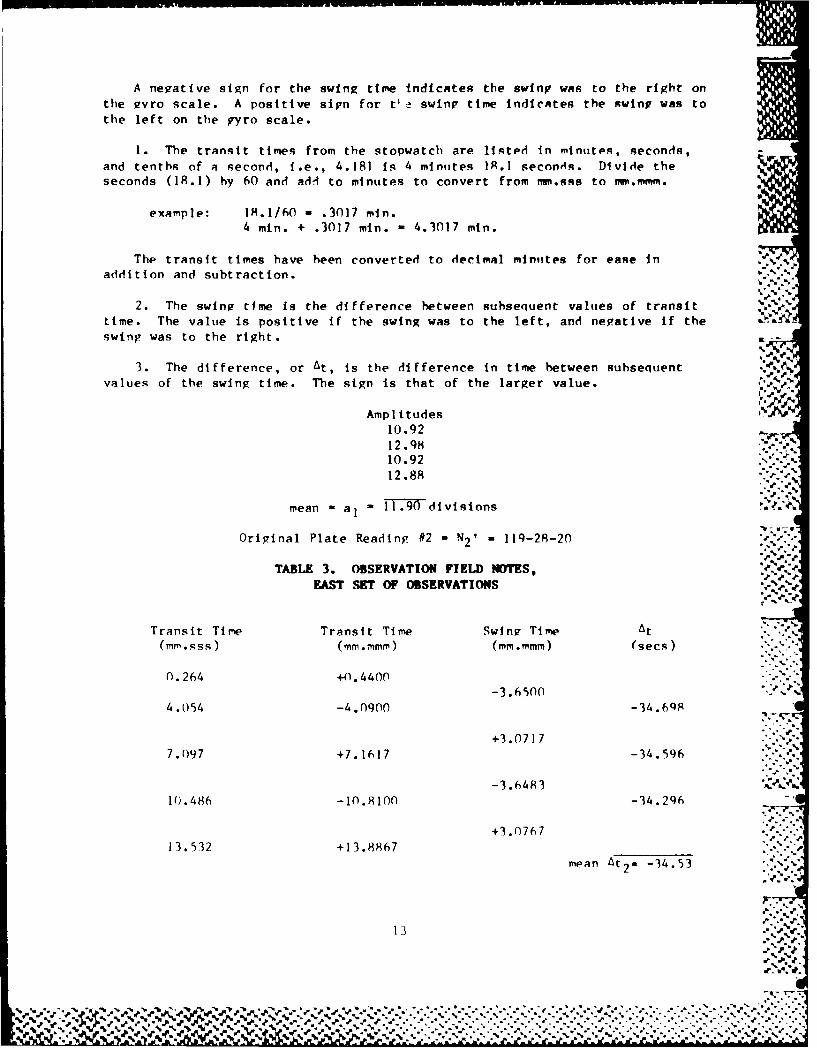
A negative sign for the swing time Indicates the swing was to the right onthe gvro scale. A positive sign for tl e swing time indicates the swing was tothe left on the gyro scale.
1. The transit times from the stopwatch are listed in minutes, seconds,and tenths of a second, i.e., 4.181 is 4 minutes 1.1 seconeIs. Divide theseconds (18.1) by 60 and ad-9 to minutes to convert from mm.sss to mm.mMm.
example: 18.1/60 - .3017 min.4 min. + .3017 min. - 4.3017 min.
The transit times have been converted to decimal minutes for ease inaddition and subtraction. , %'% % '.
2. The swing time is the difference between subsequent values of transittime. The value is positive if the swing was to the left, and negative if theswing was to the right. .
3. The difference, or At, is the difference in time between subsequentvalues of the swing time. The sign is that of the larger value.
Amplitudes
10.9212.9H10.9212.88
mean a1 11.90 divisions ,
Original Plate Reading #2 - N2 ' = 119-28-20
TABLE 3. OBSERVATION FIELD NOTES,•e
EAST SET OF OBSERVATIONS
Transit Time Transit Time Swing Time At(mm.ss) (mM .mmf') (MM.mm) (secs)
0.264 +n.4400
-3.65o ", J.4.054 -4.0900 -34 .69F
+3.0717 -
7.097 +7.1617 -34.596
-3.6483 .~
10.486 -10.8100 -34.296
+ . 76713.532 +13.8867 "',"""
mean At2 = -34.53 V
13
. + €.-.. , •...................- . . .....................-....-... .. ...... .. ...%,-... --
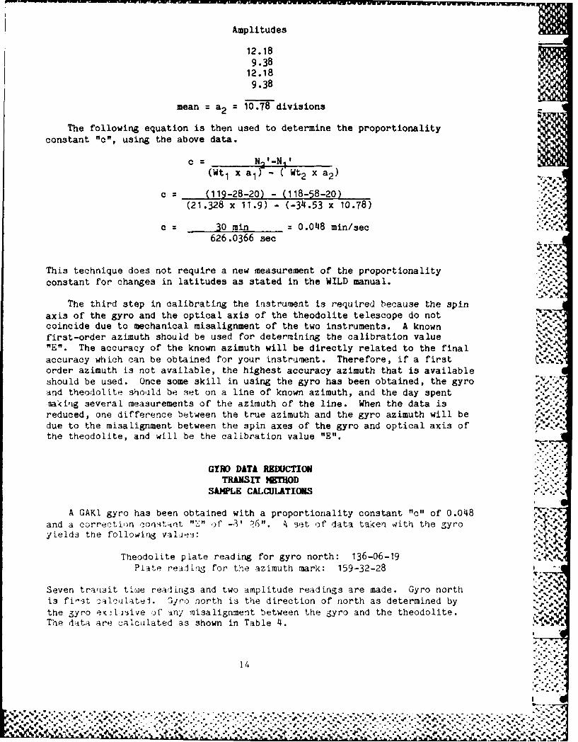
Amplitudes
12.189.3812.189.38
mean a2 = 10.78 divisions
The following equation is then used to determine the proportionalityconstant "c", using the above data.
c = N ' -Nx(Wt I x a)- ( Wt2 x a2 )
c = (119-28-20) - (118-58-20)(21.328 x 11.9) - (-34.53 x 10.78)
C 30 min 0.048 min/sec626.0366 see .
This technique does not require a new measurement of the proportionalityconstant for changes in latitudes as stated in the WILD manual. ',.'.
The third step in calibrating the instrument is required because the spinaxis of the gyro and the optical axis of the theodolite telescope do notcoincide due to mechanical misalignment of the two instruments. A knownfirst-order azimuth should be used for determining the calibration value \
"V". The accuracy of the known azimuth will be directly related to the finalaccuracy which can be obtained for your instrument. Therefore, if a firstorder azimuth is not available, the highest accuracy azimuth that is availableshould be used. Once some skill in using the gyro has been obtained, the gyroand theodolite shoild be set on a line of known azimuth, and the day spenta<irg several measurements of the azimuth of the line. When the data isreduced, one difference between the true azimuth and the gyro azimuth will bedue to the misalignment between the spin axes of the gyro and optical axis of '.' '
the theodolite, and will be the calibration value "E".
GYRO DATA REDUCTIONTRANSIT HUOD
S&LE CALCULATIONS
A GAKI gyro has been obtained with a proportionality constant "c" of 0.048and a correction constant "E" ,f -3' 26". 4 set of data taken with the gyroyields the following values:
Theodolite plate reading for gyro north: 136-06-19Plate realirng for the azimuth mark: 159-32-28
Seven transit titae readings and two amplitude readings are made. Gyro northis first calcilate-l. Gyro north is the direction of north as determined by
the gyro eK lsive Jf any Misalignment between the gyro and the theodolite.The data are calculated as shown in Table 4.
14 . '
% . .. .. *.. -..-%. .,
, -- - ' ."" ' - " , - ,

TABLE ii. OBSERVATION FIELD NOTES
TRANSIT TIME TRANSIT TIME SWING TIME DIFFERENCE(MM.S S) (MM.MM ) (MM. M ) (S.MMM ) ..
(i) (2) (3) (4)0.570 0.9500 -3.3517 .. ,
4.181 4.3017 +0.0166
+3-36837.402 7.6700 +0.0150
-3.353311.014 11.0233 +0.0167
+3.370014.236 14.3933 +0.0168
-3.353217.4479 17.7465 +0.0158
+3-3690 .
21.0693 21.1155MEAN +0.0162 TI
AMPLITUDES ,.
10.58
10.63
MEAN = 10.61
The correction to the theodolite plate reading to determine gyro north is .- ".•
Corr. (sec.) c x mean difference x mean amplitude x 3600
Corr. 0.048 x (+0.0162) x 10.61 x 3600 = +29.7 arc seconds.
Gyro North is 136-06-19.0
(+) Corr. 29.7
136-06-48.7
True North is 136-06-48.7
(-) 'E' 08-26.0___ ___ ___ __ % , .'
135-58-22.7k- .1
Finally, the azimuth of the mark is: .. "- Pp...
159-32-28.0(-) 135-58-22.7
23-34-05.3
15
. 1P J'-

w~ ~~~ %w www -~ w w w .