Embed Size (px)
Citation preview
Edgeb
anders
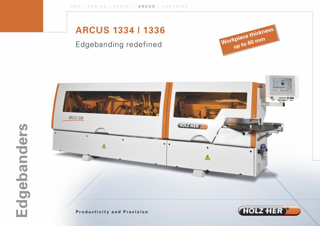
ARCUS 1334 | 1336Edgebanding redefined
U N O | A U R I G A | S P R I N T | A R C U S | C O N T R I G A
Workpiece th
ickness
up to 60 m
m
P r o d u c t i v i t y a n d P r e c i s i o n

Higher performance, greater stability, reduced space requirements as well as a machine design to set ac-cents – the ARCUS from HOLZ-HER redefines middle class edgebanding machines. ARCUS edgebandersprocess panels with thicknesses up to 60 mm and edging up to a maximum thickness of 15 mm (dependingon type). ARCUS edgebanders are available in two lengths – ARCUS 1334 and ARCUS 1336 – and with alarge number of accessory combinations. This ensures that the right machine is available for every application.The pressure bridge with rollers is a standard feature. As an option, it can be equipped with belt upper tensionfor particularly smooth transport of the work.
� Exceptional stability – welded base frame design.� Space-saving – large guard hoods lined with acoustic insulation.� Heavy-duty guidance – stable pressure bridge with two rows of pressure
rollers, high quality round bar guide.� For large panels – work support can be pulled out to 690 mm with three support feet.� Economical – locking roller for minimum work interval, work detected by light barrier.� Ergonomic – motor-driven height adjustment for pressure bridge.� Practical – two central evacuation connections� The ARCUS series is equipped with a corner copying unit as a standard feature
and a jointing cutter unit is available as an option.
Perfect attachment of various edging materials.
A R C U S 1 3 3 4 | 1 3 3 6
The New Middle Class with Top Performance
Illustrations may contain optional features.
Perfect b
onding a
nd final
processi
ng
of aluminium
edging w
ith HOLZ
-HER
aluminium
package
(option
al)

Easy handling
� Locking roller for minimumwork interval [Fig. 1].
� Simple access to pneumatic island [Fig. 2].
� Integrated chip catch bin[Fig. 3]
� Stabile run-in stop onhardened linear guides. [Fig 4]. Also with motor-driven adjustment (optional).
1
2
3
4

C O N T R O L
High standards guarantee your investment for the future
Monitor
� VGA colour monitor (PPC 221) or 15"-Touchscreen
(PPC 231) (optional feature).� Graphic user interface, all information displayed in
plaintext and/or graphic form.� Simple operation – rotating and swivelling control
panel at eye height [Fig. 1].� Dust-proof foil keypad – protects PC
for long service life.� LED display for equipment selection.
Programme List
� Programmes are simple to call with programme
names and numbers.� Large programme memory for all desired applications.� Individual selection of units with the functions
as basic setting possibilities for nominal values,
path points and tool corrections.� Set-up processes for units and their axis settings
carried out centrally and clearly by fine adjustment
to 1/100 mm (depending on equipment). 1
The HOLZ-HER PPC 221 and PPC 231 controls provide extremely high performance making them a paragonfor simple operation. A high-end industrial PC is used. Set-up and conversion of the machine has never been so rational.
PPC 231 Control with
(optional) 15" touchscreen.
Electronica
lly
controlled
set-up with
accuracy o
f 1/100 mm

Productivity through Digital Workflow
HOLZ-HER products are unbeatable when combined. The digital workflow between
the saws, edgebanders and CNC machining centres allows efficient production.
Flexible »manufacturing cells« and »lean manufacturing« are future-proof methods.
In conjunction with the HHPDE (HOLZ-HER process data acquisition) software,
time-based and computer monitoring and reporting of machine data within the
network are also possible.
Integrated Path Control
� Interval display for shortest workpiece distance.� Path points are controlled generally or in a program-specific manner.� Clear and complete acquisition of all operating data: Total running meters,
total number or parts, total number of hours, as well as running meters,
quantity and time per programme with reset function.� Service reports in plaintext.� Integrated synchronous bus system for high accuracy in
controlling the units.� Individual management for up to ten users with password
protection and individual authorization.
Equipment /Service
� USB port on board.� Keyboard port on board.� Optional network connection.� Online maintenance (optional), rapid exchange of data
with HOLZ-HER service department.� Barcode interface (optional).� Connection to HOLZ-HER process data acquisition (HHPDE)
system for direct read-out of operating data.
15" touchscreen (optional).
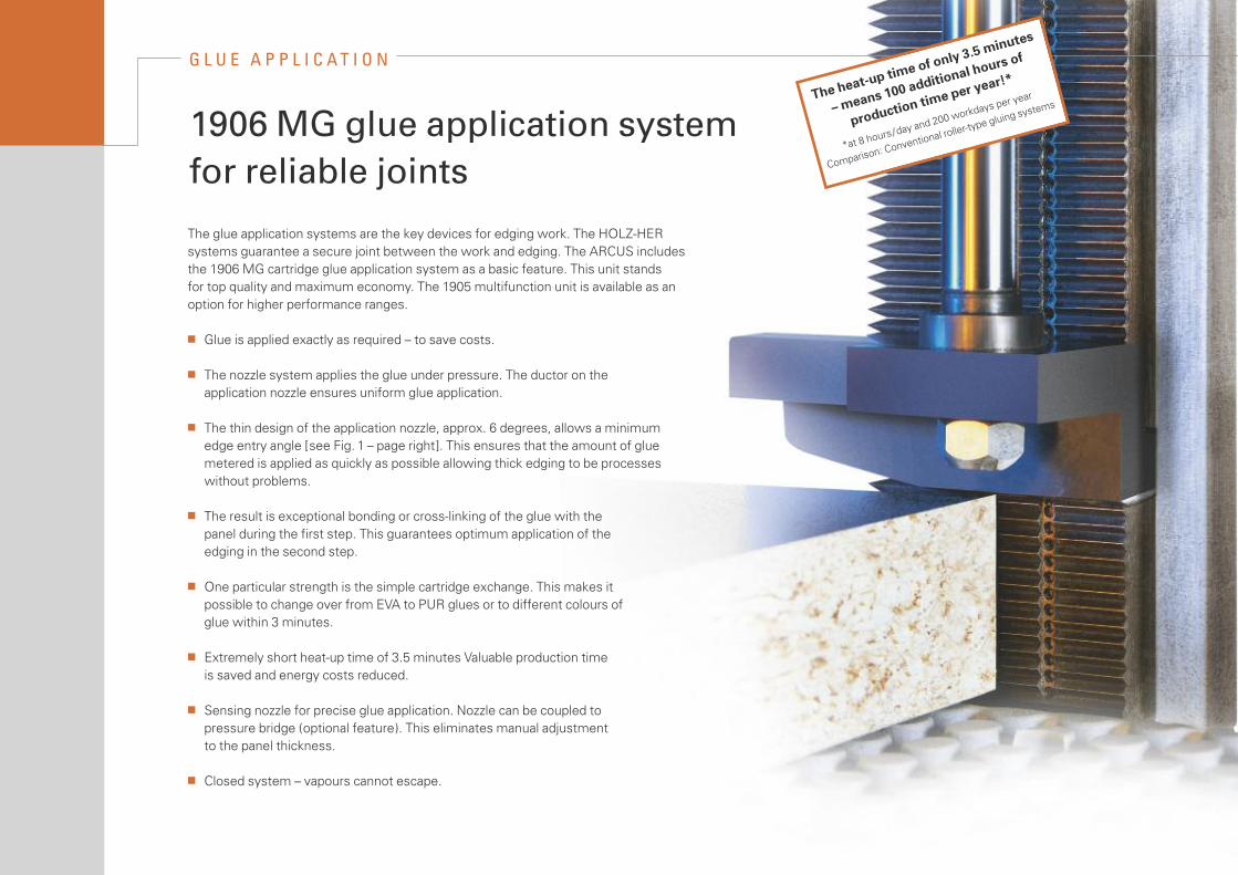
The glue application systems are the key devices for edging work. The HOLZ-HERsystems guarantee a secure joint between the work and edging. The ARCUS includesthe 1906 MG cartridge glue application system as a basic feature. This unit standsfor top quality and maximum economy. The 1905 multifunction unit is available as anoption for higher performance ranges.
� Glue is applied exactly as required – to save costs.
� The nozzle system applies the glue under pressure. The ductor on the application nozzle ensures uniform glue application.
� The thin design of the application nozzle, approx. 6 degrees, allows a minimumedge entry angle [see Fig. 1 – page right]. This ensures that the amount of glue metered is applied as quickly as possible allowing thick edging to be processes without problems.
� The result is exceptional bonding or cross-linking of the glue with the panel during the first step. This guarantees optimum application of the edging in the second step.
� One particular strength is the simple cartridge exchange. This makes it possible to change over from EVA to PUR glues or to different colours of glue within 3 minutes.
� Extremely short heat-up time of 3.5 minutes Valuable production time is saved and energy costs reduced.
� Sensing nozzle for precise glue application. Nozzle can be coupled to pressure bridge (optional feature). This eliminates manual adjustment to the panel thickness.
� Closed system – vapours cannot escape.
G L U E A P P L I C AT I O N
1906 MG glue application system for reliable joints
The heat-u
p time of o
nly 3.5 minute
s
– means 100 a
dditional ho
urs of
production
time per year!
*
*at 8 hours
/day and 20
0 workdays
per year
Comparison: Co
nventional
roller-type g
luing syste
ms

Unique and Unbeatable – The 1905 Multigluing System
� Extremely thin glue application with slotted nozzle.� For glues in cartridge or granule form.� Can hold up to four cartridges [Fig. 1] or up to 1.5 kg of granules [Fig. 3] (Optional: 5-kg shaft) [Fig. 2]� Highly flexible in daily use, time-saving and power-saving.� Easy change of shaft – just fill with new glue and continue working.� Flushing hole for automatic cleaning system – e.g. rinsing out PUR glues.� Glue does not burn – can be processed completely.
2
31
ca. 6°
More Homogeneity – Our Slotted Nozzle
� Sensor for compensation of panel
thickness tolerances.

Over 30 high performance units are availableto adapt the ARCUS series exactly to yourwork profile. Every one of these units is laid outfor high continuous stress. Pneumatic andmotor-controlled versions are available for a series of units. The stable transport chainruns on precision guides transporting the workpieces through the machine securelyand accurately with gentle surface pads.
U N I T S
High-tech for perfect edges
� Jointing cutter unit 1802
Cut edges often have smalltears in the top layer. The jointing cutter unit (optional) ensuresthat the edges to be glued areperfectly flat and prepares thepanels for edging. Low noiseZ2 jointing cutter with chip optimisation.
� Edging feed system 1903
Fully automatic, easy-to-operatefeed from rolls or as strip goods;conversion without tools.Powerful cutter for cutting offedging from rolls – maximumcross-section 135 mm2.
� Glue application system1906 MG
The patented HOLZ-HER cartridge system – nozzle technology (optional) ensuressecure retention and cleanjoints. (Nozzle design) for processing EVA and PUR adhesives; 1905 multi-systemfor glues in cartridge or granuleform [photo] (optional).

� Pressure unit 1913
High contact pressure for clean edgeadhesion. Optional with pneumaticcontrol for first roller; two subsequentpressure rollers.
Second option: All pressure rollerswith pneumatic retraction control andmotor-driven adjustment for edgethickness [Fig. shows 1913 MOT.]
� End trimming unit 1918
Tear-free trimming even athigh processing rates, can beswivelled for chamfer-typeend trimming. Two-motor endtrimmer 1918 with surface-hardened linear guides – yourguarantee for continuous cutting precision.
� Cutter unit 1828
High performance cutter unit forcoiled and cut-length edging1828 attachment for flush cutting (depending on machinemodel).
� Cutter unit 1826
1826 attachment for flush, radius andchamfer-type cutting including perma-nently installed diamond tools withchip-optimised CM technology (Leuco)[photo shows 1826 MOT 4].

� Copy cutter unit 1832
Corner copying unit for processingvertical front and rear edges withone cutting motor. Maximum feedrate 10 m/min. Maximum workthickness 45 mm.
� Grooving unit 1841
For cutting longitudinal surfaceor end grooves on edges of work;or swivelling surface/end groovingunit [photo shows 1841-3].
� Shaping cutter unit 1983
Shaping cutter unit for completepostforming profiling of verticaledges – feed rate 12 m/min.Maximum work thickness 45 mm.
� Shaping cutter unit 1833
Shaping cutter for processinglongitudinal edges, on frontrear and ends Machining withtwo cutter motors for all typesof postforming profiles [photoshow 1833 MOT 4 unit].Maximum work thickness60 mm.

� Scraper unit 1929
For perfect smoothing of radiiand chamfers on plastic edgingsOptional: with pneumatic retraction/extension or withmotor-driven fine adjustment.
� Flat scraper 1964
Clean finishing of surface – application controlled withtwo HW reversible blades – eliminates manual finishing (optional).
� Buffer unit 1940
For completely finishing edgingand surfaces for an absolutelyclean finish (optional).
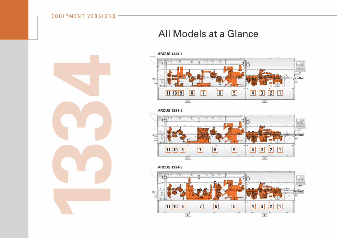
E Q U I P M E N T V E R S I O N S
All Models at a Glance
ARCUS 1334-1
ARCUS 1334-2
ARCUS 1334-3
1234567891011
123456781011
1234567810111334
1
2 3
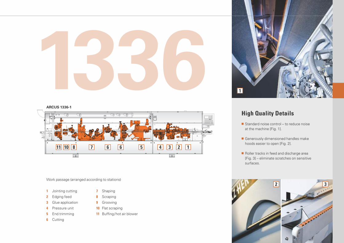
High Quality Details
� Standard noise control – to reduce noise at the machine [Fig. 1].
� Generously dimensioned handles make hoods easier to open [Fig. 2].
� Roller tracks in feed and discharge area [Fig. 3] – eliminate scratches on sensitive surfaces.
ARCUS 1336-1
1234566781011
Work passage (arranged according to stations)
1 Jointing cutting
2 Edging feed
3 Glue application
4 Pressure unit
5 End trimming
6 Cutting
7 Shaping
8 Scraping
9 Grooving
10 Flat scraping
11 Buffing/hot air blower
1336

Unit equipment
1334-1 1334-2 1334-3 1336-1
PPC 221 Control (VGA colour monitor) � � � �
PPC 231 Control (15" Touchscreen) O O O O
Roller driven pressure bridge � � � �
Belt driven pressure bridge – – O O
Jointing cutter unit 1802 O O O O
Two plunge-controlled cutting units in forward and backward direction, 2 x 2.0 kW; Diamond tools
Edging feed system 1903 � � � �
Support plate dia. 820 mm, max. loading capacity 40 mm
Glue application system 1906 MG � � � �
Nozzle application system for EVA and PUR glues in cartridge or granule form; 1.9 kW, manual replenishment; magazine capacity: one cartridge (approx. 330 g) or 1.4 kg of granule material
Glue application system 1905 O O O O
Multisystem for EVA and PUR glue in cartridge or granule form; Cartridge shaft with four cartridges (approx. 1.4 kg), Granule shaft for approx, 1.5 kg
Pressure unit 1913 � � – –
Three rollers, one roller motor-driven
Pneumatic pressure unit 1913 O O – –
With individual pneumatic control
Motor-driven pressure unit 1913 O O � �
With pneumatic control and complete motor-driven adjustment
End trimming unit 1918 � � � �
2 x 0,35 kW, 300 Hz, 9,000 rpm, swivels from 0 to 10 degrees
Pneumatic end trimming unit 1918 O O O O
Swivels pneumatically from 0 to 10 degrees
Cutter unit 1828 – – O O
Flush cutting unit, 2 x 0.6 kW, 300 Hz, 18,000 rpm
pneumatic/motor-driven multifunction unit 1826 � � O O
with pneumat./motor-driven or motor-driven adjustments;2 x 0.65 kW, 200 Hz, 12,000 rpmSwivel range 0 to 15 degrees
� = Standard | O = Optional | – = Not available

1334-1 1334-2 1334-3 1336-1
Grooving unit 1841 O – – –
1 x 3.8 kW, 200 Hz, 12,000 rpmSaw blade dia.160 mm,Cut width 4 – 9 mm
Copy cutter unit 1832 � – – –
1 x 0.22 kW, 300 Hz, 12,000 rpm, including cutter
Shaping cutter unit 1833 MOT 2 – – � �
2 x 0.65 kW, 200 Hz, 12,000 rpm, for processing longitudinal and end edges
Copy cutter unit 1983 – � – –
1 x 0.6 kW, 300 Hz, 18,000 rpm, copy cutting on end edges up to max. R = 5 mm
Scraper unit 1929 � � � �
Two scraper carriers, up to max. R = 3 mm
Pneumatic scraper unit 1929 O O O O
with pneumatic adjustments
motor-driven scraper unit 1929 O O O O
with motor-driven adjustment
Flat scraper 1964 O O O O
Insert-controlled at top and bottom
Buffer unit 1940 O O O O
2 x 0.12 kW, two textile wheels dia. 150 mm, swivels 0 to 5 degrees
Buffer unit 1944 K – – – O
with pneumatic plunge control
Buffer unit 1951 K – – – O
with oscillating buffer
Hot air blower 1995 O O O O
for heating plastic edges, eliminates white breakage
Spraying device 1856 O O O O
For application of anti-adhesion and cleaning agents A special cleaner dissolves any glue residues or contamination on edges/panels, optimising the finish.

The technical data specified is intended for reference only.HOLZ-HER woodworking machines are subject to constant development and are therefore subject to modificationwithout prior notice. The illustrations are therefore not binding. The machines illustrated may contain special features not included as standard features. Please askyour HOLZ-HER dealer for details on the features included.We reserve all rights to change design and features without prior notification.
Printed: 15th March 2010First edition: 17th April 2009
Your authorised HOLZ-HER Dealer
A
B
C
D
D
F
E
RSM 2961/1 0310 20 – UK –Printed in Germany/Imprimé en Allemagne
Working dimensions (in mm)
1334-1 1334-2 1334-3 1336-1
A 6–60* 6–60*
B 0.4– 8* 0,4–15*
C 65 max. 65 max.
D 2.5 per side 2.5 per side
E 60 min. 60 min.
F 180 180
*Depending on unit
Technical data1334-1 1334-2 1334-3 1336-1
Machine dimensions
Overall length (mm | inch) 5195 | 204.53 5195 | 204.53 5195 | 204.53 5795 | 228.15
Weight (kg) 2160 | 2160 2160 | 2160 2160 | 2160 2290 | 2290
Feed rate
Feed rate (m/min | ft /min) 10* | 32.81* 12.5 | 41.01 10–18 | 32.8–59.1 10–18 | 32.8–59.1
Dust extraction
Jointing cutter unit (m3/h | ft3/h) 360 | 12 716
Central connection (m3/h | ft3/h) 1900 | 67114
Static vacuum
Jointing cutter unit (Pa) 2100 | 2100
Central connection (Pa) 1490 | 1490
Min air velocity (m/sec | ft /m) 20 | 65.62
Jointing cutter unit connection dia. (mm| inch) 80 | 3.15
Central connection for utter unit and 180 | 7.09Scraper connection dia. (mm | inch)
Compressed air
Compressed air connection (bars) 6 | 6
*) Optional: 10–18 | 32.8–59.1
All product
brochures
can be download
ed from
www.holzher.de
1081
2791085 1027
12062233
2119
881
1609
206139
1079 337
Working dimensions
HOLZ-HER GmbHD-72608 Nürtingen
Tel.: +49 (0) 70 22 702-0Fax: +49 (0) 70 22 702-101www.holzher.de