Embed Size (px)
Citation preview
UNVENTED (VENT-FREE)NATURAL GAS LOG HEATER
VARIABLE MANUALLY-CONTROLLED MODELS ALSO DESIGN-CERTIFIED ASVENTED DECORATIVE APPLIANCES
OWNER’S OPERATION AND INSTALLATION MANUAL
Save this manual for future reference
VFN18RVFN24RVFN30R
18", 24", and 30"Remote-Ready
EMBER MASTER™
PILOT
OFF
ON
LO
REMOTE
OFF
ON
HI
WARNING: If the information in thismanual is not followed exactly, a fire orexplosion may result causing propertydamage, personal injury, or loss of life.— Do not store or use gasoline or other
flammable vapors and liquids in thevicinity of this or any other appliance.
— WHAT TO DO IF YOU SMELL GAS• Do not try to light any appliance.• Do not touch any electrical switch; do
not use any phone in your building.• Immediately call your gas supplier
from a neighbor’s phone. Follow thegas supplier’s instructions.
• If you cannot reach your gas sup-plier, call the fire department.
— Installation and service must be per-formed by a qualified installer, serviceagency, or the gas supplier.
WARNING: Improper installation, adjust-ment, alteration, service, or maintenancecan cause injury or property damage.Refer to this manual for correct installa-tion and operational procedures. For as-sistance or additional information con-sult a qualified installer, service agency,or the gas supplier.
WARNING: This is an unvented gas-fired heater. It uses air (oxygen) from the room inwhich it is installed. Provisions for adequate combustion and ventilation air must beprovided. Refer to Air for Combustion and Ventilation section on page 4 of this manual.
WARNING: This appliance is for installa-tion only in a solid-fuel burning masonryor UL127 factory-built fireplace, or in anapproved ventless firebox. It is design-certified for these installations in accor-dance with ANS Z21.11.2. Exceptions: Donot install this appliance in a factory-builtfireplace that includes instructions stat-ing it has not been tested or should not beused with unvented gas logs.
* Aftermarket: Completion of sale, not for purpose of resale, from the manufacturer
This appliance may be installed in an aftermarket*, permanently located, manufac-tured (mobile) home, where not prohibited by local codes.This appliance is only for use with the type of gas indicated on the rating plate. Thisappliance is not convertible for use with other gases.
2 105072
UNVENTED NATURAL GAS LOG HEATER
FIREPLACE MANUFACTURERS INC.
1. This appliance is only for use with thetype of gas indicated on the rating plate.This appliance is not convertible for usewith other gases.
2. If you smell gas• shut off gas supply• do not try to light any appliance• do not touch any electrical switch; do
not use any phone in your building• immediately call your gas supplier
from a neighbor’s phone. Follow thegas supplier’s instructions
• if you cannot reach your gas supplier,call the fire department
3. This heater shall not be installed in abedroom or bathroom unless installedas a vented appliance (see InstallingDamper Clamp Accessory for VentedOperation, page 10).
SAFETYINFORMATION
DANGER: Carbon monoxidepoisoning may lead to death!
Carbon Monoxide Poisoning: Early signsof carbon monoxide poisoning resemble theflu, with headaches, dizziness, or nausea. Ifyou have these signs, the heater may not beworking properly. Get fresh air at once!Have heater serviced. Some people are moreaffected by carbon monoxide than others.These include pregnant women, people withheart or lung disease or anemia, those underthe influence of alcohol, and those at highaltitudes.
Natural Gas: Natural gas is odorless. Anodor-making agent is added to the gas. Theodor helps you detect a gas leak. However,the odor added to the gas can fade. Gas maybe present even though no odor exists.
Make certain you read and understand allwarnings. Keep this manual for reference. Itis your guide to safe and proper operation ofthis heater.
WARNINGS
IMPORTANT: Read this owner’smanual carefully and completelybefore trying to assemble, oper-ate, or service this heater. Im-proper use of this heater can causeserious injury or death from burns,fire, explosion, electrical shock,and carbon monoxide poisoning.
4. Before installing in a solid fuel burn-ing fireplace, the chimney flue and fire-box must be cleaned of soot, creosote,ashes, and loose paint by a qualifiedchimney cleaner. Creosote will igniteif highly heated. Inspect chimney fluefor damage. If damaged, operate heaterwith flue damper closed.
5. If fireplace has glass doors, never op-erate this heater with glass doors closed.If you operate heater with doors closed,heat buildup inside fireplace will causeglass to burst. Also if fireplace open-ing has vents at the bottom, you mustopen the vents before operating heater.
6. This log heater is designed to besmokeless. If logs ever appear tosmoke, turn off heater and call a quali-fied service person. Note: During ini-tial operation, slight smoking mayoccur due to log curing and heaterburning manufacturing residues.
7. To prevent the creation of soot, followthe instructions in Cleaning and Main-tenance, page 17.
8. Before using furniture polish, wax, car-pet cleaner, or similar products, turnheater off. If heated, the vapors fromthese products may create a white pow-der residue within burner box or onadjacent walls or furniture.
9. This heater needs fresh, outside air ven-tilation to run properly. This heater hasan Oxygen Depletion Sensing (ODS)safety shutoff system. The ODS shutsdown the heater if not enough fresh airis available. See Air for Combustionand Ventilation, pages 4 through 6. Ifheater keeps shutting off, see Trouble-shooting, pages 18 through 20.
10. Do not run heater• where flammable liquids or vapors
are used or stored• under dusty conditions
11. Do not use this heater to cook food orburn paper or other objects.
12. Do not use heater if any part has beenexposed to or under water. Immediatelycall a qualified service technician to in-spect the room heater and to replace anypart of the control system and any gascontrol which has been under water.
13. Do not operate heater if any log is bro-ken. Do not operate heater if a log ischipped (dime-sized or larger).
WARNING: Any change tothis heater or its controls can bedangerous.
WARNING: Do not allow fansto blow directly into the fireplace.Avoid any drafts that alter burnerflame patterns. Ceiling fans cancreate drafts that alter burnerflame patterns. Altered burnerpatterns can cause sooting.
WARNING: Do not use ablower insert, heat exchangerinsert, or other accessory not ap-proved for use with this heater.
Due to high temperatures, theappliance should be located outof traffic and away from furnitureand draperies.
Do not place clothing or otherflammable material on or nearthe appliance. Never place anyobjects on the heater.
Heater base assembly becomesvery hot when running heater. Keepchildren and adults away from hotsurface to avoid burns or clothingignition. Heater will remain hot fora time after shutdown. Allow sur-face to cool before touching.
Carefully supervise young chil-dren when they are in the roomwith heater. When using the hand-held remote accessory, keep se-lector switch in the OFF positionto prevent children from turningon burners with remote.
You must operate this heater witha fireplace screen in place. Makesure fireplace screen is closedbefore running heater.
Keep the appliance area clear andfree from combustible materials,gasoline, and other flammablevapors and liquids.
3105072
OWNER’S MANUAL
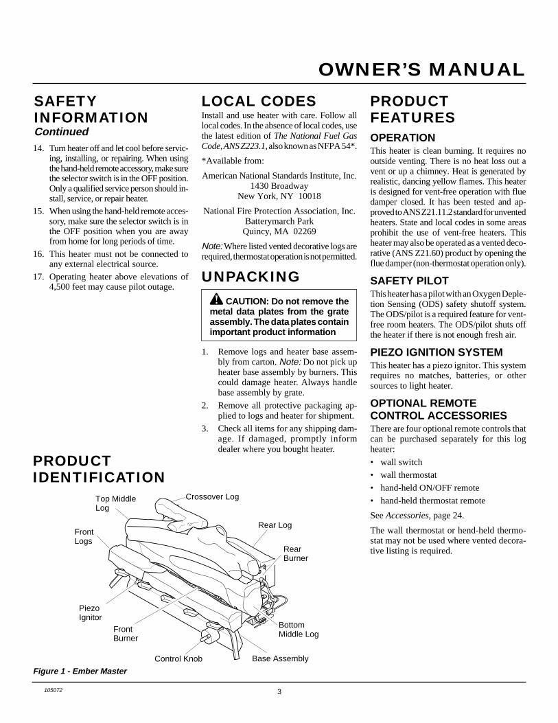
PRODUCTIDENTIFICATION
Figure 1 - Ember Master
Install and use heater with care. Follow alllocal codes. In the absence of local codes, usethe latest edition of The National Fuel GasCode, ANS Z223.1, also known as NFPA 54*.
*Available from:
American National Standards Institute, Inc.1430 Broadway
New York, NY 10018
National Fire Protection Association, Inc.Batterymarch Park
Quincy, MA 02269
Note: Where listed vented decorative logs arerequired, thermostat operation is not permitted.
CAUTION: Do not remove themetal data plates from the grateassembly. The data plates containimportant product information
1. Remove logs and heater base assem-bly from carton. Note: Do not pick upheater base assembly by burners. Thiscould damage heater. Always handlebase assembly by grate.
2. Remove all protective packaging ap-plied to logs and heater for shipment.
3. Check all items for any shipping dam-age. If damaged, promptly informdealer where you bought heater.
PRODUCTFEATURESOPERATIONThis heater is clean burning. It requires nooutside venting. There is no heat loss out avent or up a chimney. Heat is generated byrealistic, dancing yellow flames. This heateris designed for vent-free operation with fluedamper closed. It has been tested and ap-proved to ANS Z21.11.2 standard for unventedheaters. State and local codes in some areasprohibit the use of vent-free heaters. Thisheater may also be operated as a vented deco-rative (ANS Z21.60) product by opening theflue damper (non-thermostat operation only).
SAFETY PILOTThis heater has a pilot with an Oxygen Deple-tion Sensing (ODS) safety shutoff system.The ODS/pilot is a required feature for vent-free room heaters. The ODS/pilot shuts offthe heater if there is not enough fresh air.
PIEZO IGNITION SYSTEMThis heater has a piezo ignitor. This systemrequires no matches, batteries, or othersources to light heater.
OPTIONAL REMOTECONTROL ACCESSORIESThere are four optional remote controls thatcan be purchased separately for this logheater:
• wall switch
• wall thermostat
• hand-held ON/OFF remote
• hand-held thermostat remote
See Accessories, page 24.
The wall thermostat or hend-held thermo-stat may not be used where vented decora-tive listing is required.
14. Turn heater off and let cool before servic-ing, installing, or repairing. When usingthe hand-held remote accessory, make surethe selector switch is in the OFF position.Only a qualified service person should in-stall, service, or repair heater.
15. When using the hand-held remote acces-sory, make sure the selector switch is inthe OFF position when you are awayfrom home for long periods of time.
16. This heater must not be connected toany external electrical source.
17. Operating heater above elevations of4,500 feet may cause pilot outage.
LOCAL CODESSAFETYINFORMATIONContinued
FrontLogs
Crossover Log
Rear Log
RearBurner
BottomMiddle Log
Base AssemblyControl Knob
FrontBurner
PiezoIgnitor
Top MiddleLog
UNPACKING
4 105072
UNVENTED NATURAL GAS LOG HEATER
FIREPLACE MANUFACTURERS INC.
Today’s homes are built more energy effi-cient than ever. New materials, increasedinsulation, and new construction methodshelp reduce heat loss in homes. Home ownersweather strip and caulk around windows anddoors to keep the cold air out and the warm airin. During heating months, home ownerswant their homes as airtight as possible.
While it is good to make your home energyefficient, your home needs to breathe. Freshair must enter your home. All fuel-burningappliances need fresh air for proper com-bustion and ventilation.
Exhaust fans, fireplaces, clothes dryers, andfuel burning appliances draw air from thehouse to operate. You must provide ad-equate fresh air for these appliances. Thiswill insure proper venting of vented fuel-burning appliances.
AIR FORCOMBUSTION ANDVENTILATION
WARNING: This heater shallnot be installed in a confined spaceor unusually tight constructionunless provisions are providedfor adequate combustion and ven-tilation air. Read the following in-structions to insure proper freshair for this and other fuel-burningappliances in your home.
PROVIDING ADEQUATEVENTILATIONThe following are excerpts from NationalFuel Gas Code, NFPA 54/ANS Z223.1, Sec-tion 5.3, Air for Combustion and Ventilation.
All spaces in homes fall into one of the threefollowing ventilation classifications:
1. Unusually Tight Construction
2. Unconfined Space
3. Confined Space
The information on pages 4 through 6 willhelp you classify your space and provideadequate ventilation.
Unusually Tight Construction
The air that leaks around doors and win-dows may provide enough fresh air forcombustion and ventilation. However, inbuildings of unusually tight construction,you must provide additional fresh air.
Unusually tight construction is de-fined as construction where:a. walls and ceilings exposed to the
outside atmosphere have a con-tinuous water vapor retarder witha rating of one perm (6x10-11 kgper pa-sec-m2) or less with open-ings gasketed or sealed and
b. weather stripping has beenadded on openable windows anddoors and
c. caulking or sealants are appliedto areas such as joints aroundwindow and door frames, be-tween sole plates and floors, be-tween wall-ceiling joints, be-tween wall panels, at penetra-tions for plumbing, electrical, andgas lines, and at other openings.
If your home meets all of the threecriteria above, you must provide ad-ditional fresh air. See Ventilation AirFrom Outdoors, page 6.
If your home does not meet all of thethree criteria above, proceed to De-termining Fresh-Air Flow for HeaterLocation, page 5.
Confined and Unconfined Space
The National Fuel Gas Code, ANS Z223.1defines a confined space as a space whosevolume is less than 50 cubic feet per 1,000Btu per hour (4.8 m3 per kw) of the aggre-gate input rating of all appliances installedin that space and an unconfined space as aspace whose volume is not less than 50cubic feet per 1,000 Btu per hour (4.8 m3 perkw) of the aggregate input rating of allappliances installed in that space. Roomscommunicating directly with the space inwhich the appliances are installed*, throughopenings not furnished with doors, are con-sidered a part of the unconfined space.
This heater shall not be installed in a con-fined space or unusually tight constructionunless provisions are provided for adequatecombustion and ventilation air.
* Adjoining rooms are communicating onlyif there are doorless passageways or ventila-tion grills between them.
5105072
OWNER’S MANUAL
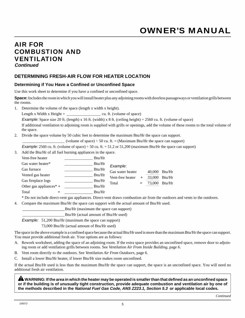
DETERMINING FRESH-AIR FLOW FOR HEATER LOCATION
Determining if You Have a Confined or Unconfined Space
Use this work sheet to determine if you have a confined or unconfined space.
Space: Includes the room in which you will install heater plus any adjoining rooms with doorless passageways or ventilation grills betweenthe rooms.
1. Determine the volume of the space (length x width x height).
Length x Width x Height = _________________ cu. ft. (volume of space)
Example: Space size 20 ft. (length) x 16 ft. (width) x 8 ft. (ceiling height) = 2560 cu. ft. (volume of space)
If additional ventilation to adjoining room is supplied with grills or openings, add the volume of these rooms to the total volume ofthe space.
2. Divide the space volume by 50 cubic feet to determine the maximum Btu/Hr the space can support.
_____________________ (volume of space) ÷ 50 cu. ft. = (Maximum Btu/Hr the space can support)
Example: 2560 cu. ft. (volume of space) ÷ 50 cu. ft. = 51.2 or 51,200 (maximum Btu/Hr the space can support)
3. Add the Btu/Hr of all fuel burning appliances in the space.
Vent-free heater ______________ Btu/Hr
Gas water heater* ______________ Btu/Hr
Gas furnace ______________ Btu/Hr
Vented gas heater ______________ Btu/Hr
Gas fireplace logs ______________ Btu/Hr
Other gas appliances* + ______________ Btu/Hr
Total = ______________ Btu/Hr
* Do not include direct-vent gas appliances. Direct-vent draws combustion air from the outdoors and vents to the outdoors.
4. Compare the maximum Btu/Hr the space can support with the actual amount of Btu/Hr used.
_____________________Btu/Hr (maximum the space can support)
_____________________Btu/Hr (actual amount of Btu/Hr used)
Example: 51,200 Btu/Hr (maximum the space can support)
73,000 Btu/Hr (actual amount of Btu/Hr used)
The space in the above example is a confined space because the actual Btu/Hr used is more than the maximum Btu/Hr the space can support.You must provide additional fresh air. Your options are as follows:
A. Rework worksheet, adding the space of an adjoining room. If the extra space provides an unconfined space, remove door to adjoin-ing room or add ventilation grills between rooms. See Ventilation Air From Inside Building, page 6.
B. Vent room directly to the outdoors. See Ventilation Air From Outdoors, page 6.
C. Install a lower Btu/Hr heater, if lower Btu/Hr size makes room unconfined.
If the actual Btu/Hr used is less than the maximum Btu/Hr the space can support, the space is an unconfined space. You will need noadditional fresh air ventilation.
Example:Gas water heater 40,000 Btu/Hr
Vent-free heater + 33,000 Btu/Hr
Total = 73,000 Btu/Hr
AIR FORCOMBUSTION ANDVENTILATIONContinued
WARNING: If the area in which the heater may be operated is smaller than that defined as an unconfined spaceor if the building is of unusually tight construction, provide adequate combustion and ventilation air by one ofthe methods described in the National Fuel Gas Code, ANS Z223.1, Section 5.3 or applicable local codes.
Continued
6 105072
UNVENTED NATURAL GAS LOG HEATER
FIREPLACE MANUFACTURERS INC.
AIR FORCOMBUSTION ANDVENTILATIONContinued
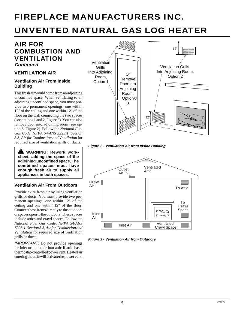
VENTILATION AIR
Ventilation Air From InsideBuilding
This fresh air would come from an adjoiningunconfined space. When ventilating to anadjoining unconfined space, you must pro-vide two permanent openings: one within12" of the ceiling and one within 12" of thefloor on the wall connecting the two spaces(see options 1 and 2, Figure 2). You can alsoremove door into adjoining room (see op-tion 3, Figure 2). Follow the National FuelGas Code, NFPA 54/ANS Z223.1, Section5.3, Air for Combustion and Ventilation forrequired size of ventilation grills or ducts.
OutletAir
VentilatedAttic
OutletAir
InletAir
Inlet Air Ventilated Crawl Space
To CrawlSpace
To Attic
OrRemoveDoor intoAdjoining
Room,Option
3
Ventilation Grills Into Adjoining Room,
Option 2
VentilationGrills
Into Adjoining Room,
Option 1
12"
12"
Figure 2 - Ventilation Air from Inside Building
Ventilation Air From Outdoors
Provide extra fresh air by using ventilationgrills or ducts. You must provide two per-manent openings: one within 12" of theceiling and one within 12" of the floor.Connect these items directly to the outdoorsor spaces open to the outdoors. These spacesinclude attics and crawl spaces. Follow theNational Fuel Gas Code, NFPA 54/ANSZ223.1, Section 5.3, Air for Combustion andVentilation for required size of ventilationgrills or ducts.
IMPORTANT: Do not provide openingsfor inlet or outlet air into attic if attic has athermostat-controlled power vent. Heated airentering the attic will activate the power vent.
Figure 3 - Ventilation Air from Outdoors
WARNING: Rework work-sheet, adding the space of theadjoining unconfined space. Thecombined spaces must haveenough fresh air to supply allappliances in both spaces.
7105072
OWNER’S MANUAL
LOG SIZING REQUIREMENTS
Minimum Firebox SizeLog Front Rear*Size Height Depth Width Width
18" 17" 14" 20" 14"24" 17" 14" 26" 18"30" 17" 14" 32" 22"
MINIMUM FIREPLACE CLEARANCETO COMBUSTIBLE MATERIALS
Log Size Side Wall Ceiling Floor*
18", 24", 30" 16" 42" 5"
*See Floor Clearances, page 9.
WARNING: A qualified ser-vice person must install heater.Follow all local codes.
WARNING: Before installingin a solid fuel burning fireplace,the chimney flue and firebox mustbe cleaned of soot, creosote,ashes and loose paint by a quali-fied chimney cleaner. Creosotewill ignite if highly heated. A dirtychimney flue may create and dis-tribute soot within the house. In-spect chimney flue for damage. Ifdamaged, operate heater with fluedamper closed.
WARNING: Seal any fresh airvents or ash clean-out doors lo-cated on floor or wall of fireplace.If not, drafting may cause pilotoutage or sooting. Use a heat-resistant sealant. Do not sealchimney flue damper.
WARNING: Never install theheater• in a bedroom or bathroom un-
less installed as a vented ap-pliance, see page 10
• in a recreational vehicle• where curtains, furniture,
clothing, or other flammableobjects are less than 42 inchesfrom the front, top, or sides ofthe heater
• in high traffic areas• in windy or drafty areas
CAUTION: This heater createswarm air currents. These currentsmove heat to wall surfaces next toheater. Installing heater next tovinyl or cloth wall coverings oroperating heater where impurities(such as tobacco smoke, aromaticcandles, cleaning fluids, oil orkerosene lamps, etc.) in the airexist, may discolor walls.
IMPORTANT: Vent-free heaters add mois-ture to the air. Although this is beneficial,installing heater in rooms without enoughventilation air may cause mildew to formfrom too much moisture. See Air for Com-bustion and Ventilation, pages 4 through 6.
CHECK GAS TYPEUse only natural gas. If your gas supply is notnatural gas, do not install heater. Call dealerwhere you bought heater for proper type heater.
INSTALLATION
WARNING: Make sure theselector switch is in the OFF po-sition before installing heater.
INSTALLATION ANDCLEARANCES(Vent-Free Operation Only)
WARNING: Maintain the mini-mum clearances. If you can, pro-vide greater clearances fromfloor, ceiling, and adjoining wall.
NOTICE: State or local codes mayonly allow operation of this appli-ance in a vented configuration.Check your state or local codes.
*Measured at 14" depth
NOTICE: This heater is intendedfor use as supplemental heat. Usethis heater along with your pri-mary heating system. Do not in-stall this heater as your primaryheat source. If you have a centralheating system, you may runsystem’s circulating blower whileusing heater. This will help circu-late the heat throughout thehouse. In the event of a poweroutage, you can use this heateras your primary heat source.
Continued
Carefully follow the instructions below. Thiswill ensure safe installation into a masonry,UL127-listed manufactured fireplace, orlisted vent-free firebox.
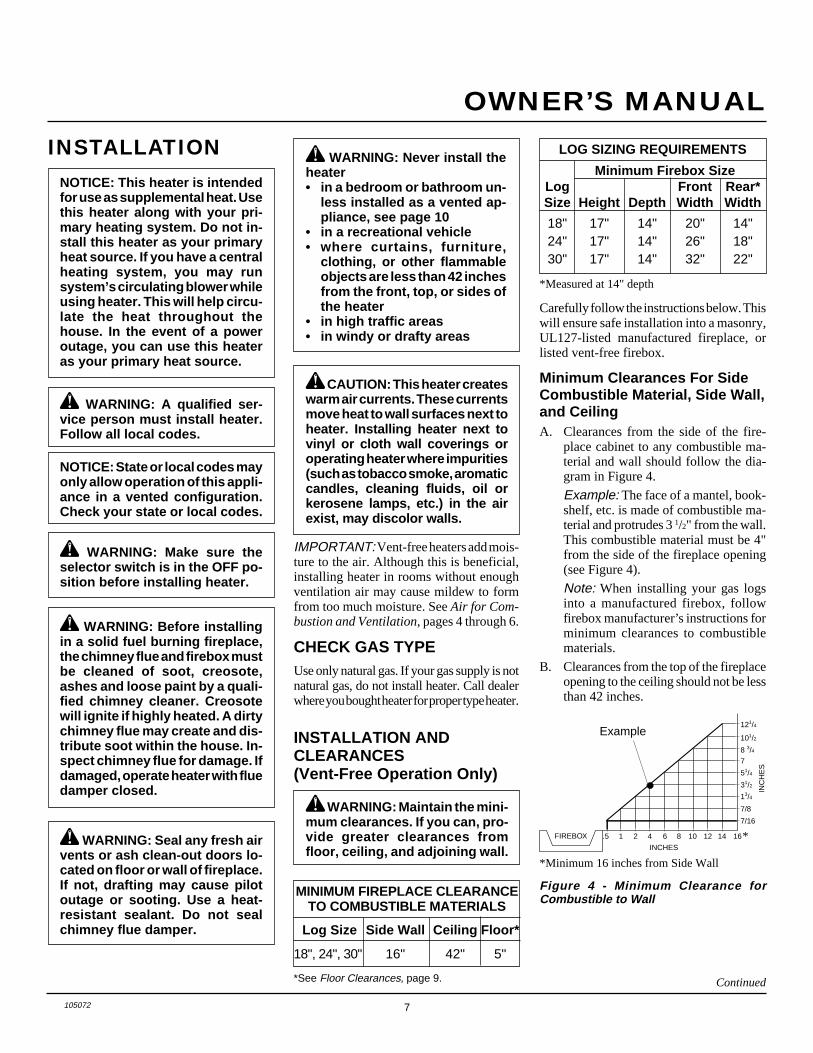
Minimum Clearances For SideCombustible Material, Side Wall,and CeilingA. Clearances from the side of the fire-
place cabinet to any combustible ma-terial and wall should follow the dia-gram in Figure 4.
Example: The face of a mantel, book-shelf, etc. is made of combustible ma-terial and protrudes 3 1/2" from the wall.This combustible material must be 4"from the side of the fireplace opening(see Figure 4).
Note: When installing your gas logsinto a manufactured firebox, followfirebox manufacturer’s instructions forminimum clearances to combustiblematerials.
B. Clearances from the top of the fireplaceopening to the ceiling should not be lessthan 42 inches.
Figure 4 - Minimum Clearance forCombustible to Wall
.5 2
7/16
7/8
13/4
31/2
51/4
7
8 3/4
101/2
121/4
1 4 6 8 10 12 14 16FIREBOX
INCHES
INC
HE
S
*Minimum 16 inches from Side Wall
*
Example
8 105072
UNVENTED NATURAL GAS LOG HEATER
FIREPLACE MANUFACTURERS INC.
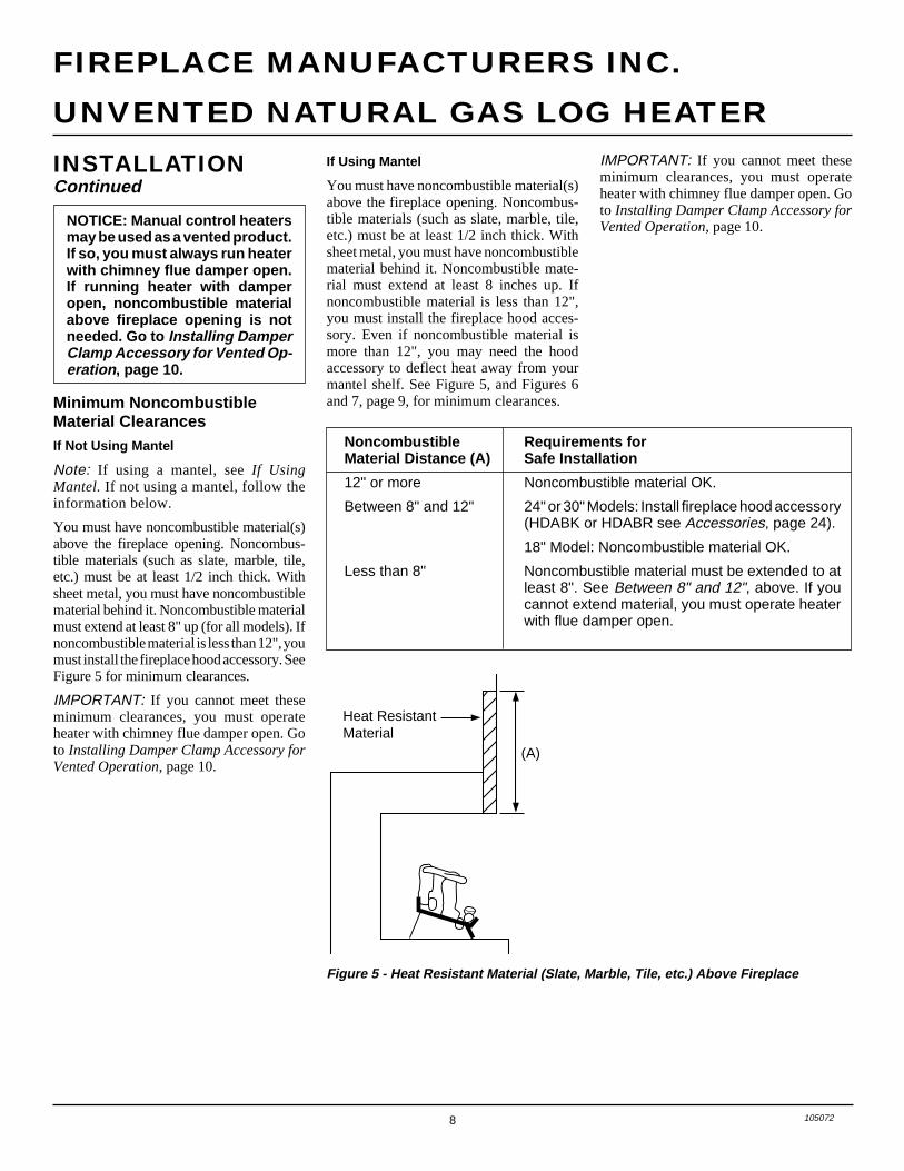
Heat ResistantMaterial
(A)
Figure 5 - Heat Resistant Material (Slate, Marble, Tile, etc.) Above Fireplace
INSTALLATIONContinued
If Using Mantel
You must have noncombustible material(s)above the fireplace opening. Noncombus-tible materials (such as slate, marble, tile,etc.) must be at least 1/2 inch thick. Withsheet metal, you must have noncombustiblematerial behind it. Noncombustible mate-rial must extend at least 8 inches up. Ifnoncombustible material is less than 12",you must install the fireplace hood acces-sory. Even if noncombustible material ismore than 12", you may need the hoodaccessory to deflect heat away from yourmantel shelf. See Figure 5, and Figures 6and 7, page 9, for minimum clearances.Minimum Noncombustible
Material ClearancesIf Not Using Mantel
Note: If using a mantel, see If UsingMantel. If not using a mantel, follow theinformation below.
You must have noncombustible material(s)above the fireplace opening. Noncombus-tible materials (such as slate, marble, tile,etc.) must be at least 1/2 inch thick. Withsheet metal, you must have noncombustiblematerial behind it. Noncombustible materialmust extend at least 8" up (for all models). Ifnoncombustible material is less than 12", youmust install the fireplace hood accessory. SeeFigure 5 for minimum clearances.
IMPORTANT: If you cannot meet theseminimum clearances, you must operateheater with chimney flue damper open. Goto Installing Damper Clamp Accessory forVented Operation, page 10.
IMPORTANT: If you cannot meet theseminimum clearances, you must operateheater with chimney flue damper open. Goto Installing Damper Clamp Accessory forVented Operation, page 10.NOTICE: Manual control heaters
may be used as a vented product.If so, you must always run heaterwith chimney flue damper open.If running heater with damperopen, noncombustible materialabove fireplace opening is notneeded. Go to Installing DamperClamp Accessory for Vented Op-eration, page 10.
Noncombustible Requirements forMaterial Distance (A) Safe Installation
12" or more Noncombustible material OK.
Between 8" and 12" 24" or 30" Models: Install fireplace hood accessory(HDABK or HDABR see Accessories, page 24).
18" Model: Noncombustible material OK.
Less than 8" Noncombustible material must be extended to atleast 8". See Between 8" and 12", above. If youcannot extend material, you must operate heaterwith flue damper open.
9105072
OWNER’S MANUAL
Minimum Non-Combustible Material
Minimum Non-Combustible Material Height
Distances to Underside ofMantel
Top of FireplaceOpening
Underside ofMantel Shelf
12"
8"
(A)
18"
14"
20"
17"
22"
19"
24"
20"
All minimum distances arein inches
Log Set24"/30" Models
18" Model
2 1/2"
6"
8"
10"Mantel Shelf
Minimum Non-Combustible Material 8"
Min.12" 15" 18"
All minimum distances arein inches
Log Sets
18" & 24" Models20"
2 1/2"
6"
8"
10"
12"
Distances to Underside ofMantel
Hood(HDABK,HDABR)
Top of FireplaceOpening
Underside ofMantel Shelf
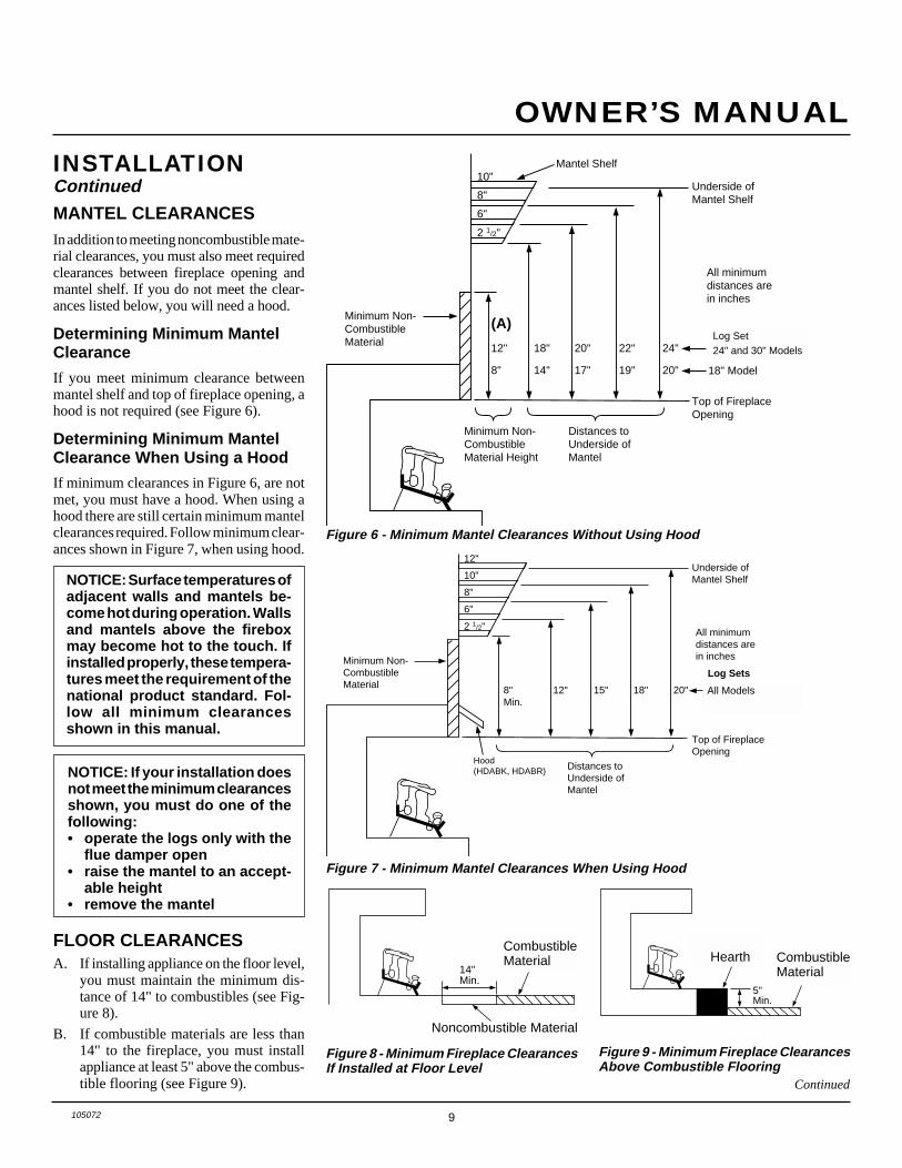
MANTEL CLEARANCESIn addition to meeting noncombustible mate-rial clearances, you must also meet requiredclearances between fireplace opening andmantel shelf. If you do not meet the clear-ances listed below, you will need a hood.
Determining Minimum MantelClearance
If you meet minimum clearance betweenmantel shelf and top of fireplace opening, ahood is not required (see Figure 6).
Determining Minimum MantelClearance When Using a Hood
If minimum clearances in Figure 6, are notmet, you must have a hood. When using ahood there are still certain minimum mantelclearances required. Follow minimum clear-ances shown in Figure 7, when using hood.
Figure 6 - Minimum Mantel Clearances Without Using Hood
Figure 7 - Minimum Mantel Clearances When Using Hood
Continued
INSTALLATIONContinued
14"Min.
Combustible Material
Non-Combustible Material
Hearth
5"Min.
Combustible Material
FLOOR CLEARANCESA. If installing appliance on the floor level,
you must maintain the minimum dis-tance of 14" to combustibles (see Fig-ure 8).
B. If combustible materials are less than14" to the fireplace, you must installappliance at least 5" above the combus-tible flooring (see Figure 9).
Figure 8 - Minimum Fireplace ClearancesIf Installed at Floor Level
Figure 9 - Minimum Fireplace ClearancesAbove Combustible Flooring
NOTICE: If your installation doesnot meet the minimum clearancesshown, you must do one of thefollowing:• operate the logs only with the
flue damper open• raise the mantel to an accept-
able height• remove the mantel
24" Models
Hood(HDABK, HDABR)
Noncombustible Material
CombustibleMaterial Combustible
MaterialHearth
Log Set24" and 30" Models
All Models
NOTICE: Surface temperatures ofadjacent walls and mantels be-come hot during operation. Wallsand mantels above the fireboxmay become hot to the touch. Ifinstalled properly, these tempera-tures meet the requirement of thenational product standard. Fol-low all minimum clearancesshown in this manual.
10 105072
UNVENTED NATURAL GAS LOG HEATER
FIREPLACE MANUFACTURERS INC.
INSTALLATIONContinued
INSTALLING HEATER BASEASSEMBLY
WARNING: You must securethis heater to fireplace floor. Ifnot, heater will move when youadjust controls. Moving heatermay cause a gas leak.
WARNING: If installing in asunken fireplace, special care isneeded. You must raise thefireplace floor to allow access toheater control panel. This willinsure adequate air flow andguard against sooting. Raisefireplace floor with non-combustible material. Make surematerial is secure.
CAUTION: Do not pick upheater base assembly by burn-ers. This could damage heater.Only handle base assembly bygrates.
IMPORTANT: Make sure the heater burn-ers are level. If heater is not level, heater willnot work properly.
CAUTION: Do not removethe metal data plates attached tothe heater base assembly. Thedata plates contain importantwarranty information.
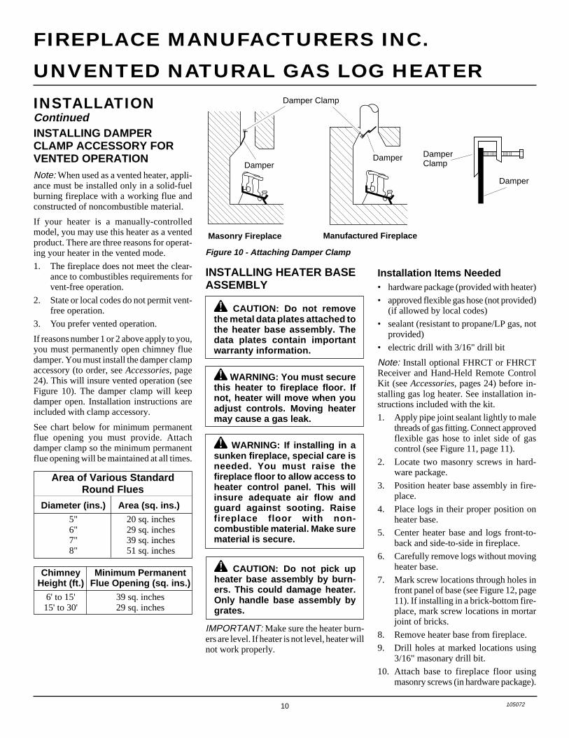
INSTALLING DAMPERCLAMP ACCESSORY FORVENTED OPERATIONNote: When used as a vented heater, appli-ance must be installed only in a solid-fuelburning fireplace with a working flue andconstructed of noncombustible material.
If your heater is a manually-controlledmodel, you may use this heater as a ventedproduct. There are three reasons for operat-ing your heater in the vented mode.
1. The fireplace does not meet the clear-ance to combustibles requirements forvent-free operation.
2. State or local codes do not permit vent-free operation.
3. You prefer vented operation.
If reasons number 1 or 2 above apply to you,you must permanently open chimney fluedamper. You must install the damper clampaccessory (to order, see Accessories, page24). This will insure vented operation (seeFigure 10). The damper clamp will keepdamper open. Installation instructions areincluded with clamp accessory.
See chart below for minimum permanentflue opening you must provide. Attachdamper clamp so the minimum permanentflue opening will be maintained at all times.
Chimney Minimum PermanentHeight (ft.) Flue Opening (sq. ins.)
6' to 15' 39 sq. inches15' to 30' 29 sq. inches
Area of Various StandardRound Flues
Diameter (ins.) Area (sq. ins.)5" 20 sq. inches6" 29 sq. inches7" 39 sq. inches8" 51 sq. inches
Figure 10 - Attaching Damper Clamp
Damper
Damper Clamp
DamperClamp
Damper
Damper
Manufactured FireplaceMasonry Fireplace
Installation Items Needed• hardware package (provided with heater)
• approved flexible gas hose (not provided)(if allowed by local codes)
• sealant (resistant to propane/LP gas, notprovided)
• electric drill with 3/16" drill bit
Note: Install optional FHRCT or FHRCTReceiver and Hand-Held Remote ControlKit (see Accessories, pages 24) before in-stalling gas log heater. See installation in-structions included with the kit.
1. Apply pipe joint sealant lightly to malethreads of gas fitting. Connect approvedflexible gas hose to inlet side of gascontrol (see Figure 11, page 11).
2. Locate two masonry screws in hard-ware package.
3. Position heater base assembly in fire-place.
4. Place logs in their proper position onheater base.
5. Center heater base and logs front-to-back and side-to-side in fireplace.
6. Carefully remove logs without movingheater base.
7. Mark screw locations through holes infront panel of base (see Figure 12, page11). If installing in a brick-bottom fire-place, mark screw locations in mortarjoint of bricks.
8. Remove heater base from fireplace.
9. Drill holes at marked locations using3/16" masonary drill bit.
10. Attach base to fireplace floor usingmasonry screws (in hardware package).
11105072
OWNER’S MANUALInstallation Items Needed
Before installing heater, make sure you havethe items listed below.
• piping (check local codes)
• sealant (resistant to propane/LP gas)
• equipment shutoff valve *
• test gauge connection *
• sediment trap
• tee joint
• pipe wrench
* An CSA design-certified equipment shutoffvalve with 1/8" NPT tap is an acceptablealternative to test gauge connection.
CONNECTING TO GASSUPPLY
WARNING A qualified serviceperson must connect heater togas supply. Follow all local codes.
INSTALLATIONContinued
WARNING: Never connectheater to private (non-utility) gaswells. This gas is commonlyknown as well-head gas.
CAUTION: Use only new,black iron or steel pipe. Inter-nally-tinned copper tubing maybe used in certain areas. Checkyour local codes. Use pipe of 1/2"diameter or greater to allowproper gas volume to heater. Ifpipe is too small, undue loss ofpressure will occur.
Continued
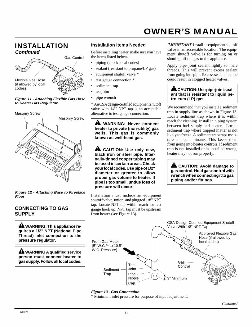
Installation must include an equipmentshutoff valve, union, and plugged 1/8" NPTtap. Locate NPT tap within reach for testgauge hook up. NPT tap must be upstreamfrom heater (see Figure 13).
CAUTION: Avoid damage togas control. Hold gas control withwrench when connecting it to gaspiping and/or fittings.
* Minimum inlet pressure for purpose of input adjustment.Figure 13 - Gas Connection
Figure 11 - Attaching Flexible Gas Hoseto Heater Gas Regulator
Figure 12 - Attaching Base to FireplaceFloor
Gas Control
Flexible Gas Hose(if allowed by localcodes)
Masonry ScrewMasonry Screw
TeeJointPipeNippleCap
3" Minimum
SedimentTrap
GasControl
CSA Design-Certified Equipment ShutoffValve With 1/8" NPT Tap
Approved Flexible GasHose (if allowed bylocal codes)
CAUTION: Use pipe joint seal-ant that is resistant to liquid pe-troleum (LP) gas.
IMPORTANT: Install an equipment shutoffvalve in an accessible location. The equip-ment shutoff valve is for turning on orshutting off the gas to the appliance.
Apply pipe joint sealant lightly to malethreads. This will prevent excess sealantfrom going into pipe. Excess sealant in pipecould result in clogged heater valves.
From Gas Meter(5" W.C.** to 10.5"W.C. Pressure)
WARNING: This appliance re-quires a 1/2" NPT (National PipeThread) inlet connection to thepressure regulator.
We recommend that you install a sedimenttrap in supply line as shown in Figure 13.Locate sediment trap where it is withinreach for cleaning. Install in piping systembetween fuel supply and heater. Locatesediment trap where trapped matter is notlikely to freeze. A sediment trap traps mois-ture and contaminants. This keeps themfrom going into heater controls. If sedimenttrap is not installed or is installed wrong,heater may not run properly.
12 105072
UNVENTED NATURAL GAS LOG HEATER
FIREPLACE MANUFACTURERS INC.
ONPOSITION
OFFPOSITION
Open
ClosedEquipmentShutoffValve
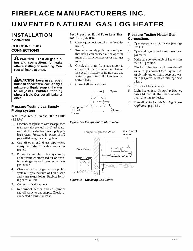
Figure 15 - Checking Gas Joints
Gas Meter
Equipment Shutoff Valve Gas ControlLocation
Test Pressures Equal To or Less Than1/2 PSIG (3.5 kPa)
1. Close equipment shutoff valve (see Fig-ure 14).
2. Pressurize supply piping system by ei-ther using compressed air or openingmain gas valve located on or near gasmeter.
3. Check all joints from gas meter toequipment shutoff valve (see Figure15). Apply mixture of liquid soap andwater to gas joints. Bubbles formingshow a leak.
4. Correct all leaks at once.
Figure 14 - Equipment Shutoff Valve
INSTALLATIONContinued
CHECKING GASCONNECTIONS
WARNING: Test all gas pip-ing and connections for leaksafter installing or servicing. Cor-rect all leaks at once.
WARNING: Never use an openflame to check for a leak. Apply amixture of liquid soap and waterto all joints. Bubbles formingshow a leak. Correct all leaks atonce.
Pressure Testing gas SupplyPiping system
Test Pressures In Excess Of 1/2 PSIG(3.5 kPa)
1. Disconnect appliance with its appliancemain gas valve (control valve) and equip-ment shutoff valve from gas supply pip-ing system. Pressures in excess of 1/2psig will damage heater regulator.
2. Cap off open end of gas pipe whereequipment shutoff valve was con-nected.
3. Pressurize supply piping system byeither using compressed air or open-ing main gas valve located on or neargas meter.
4. Check all joints of gas supply pipingsystem. Apply mixture of liquid soapand water to gas joints. Bubbles form-ing show a leak.
5. Correct all leaks at once.
6. Reconnect heater and equipmentshutoff valve to gas supply. Check re-connected fittings for leaks.
Pressure Testing Heater GasConnections1. Open equipment shutoff valve (see Fig-
ure 14).
2. Open main gas valve located on or neargas meter.
3. Make sure control knob of heater is inthe OFF position.
4. Check all joints from equipment shutoffvalve to gas control (see Figure 15).Apply mixture of liquid soap and wa-ter to gas joints. Bubbles forming showa leak.
5. Correct all leaks at once.
6. Light heater (see Operating Heater,pages 14 through 16). Check all otherinternal joints for leaks.
7. Turn off heater (see To Turn Off Gas toAppliance, page 15).
13105072
OWNER’S MANUAL
Rear Log (#3)Peg
GrateProng
Grate Prong
Groove inBack of LogGroove in
Back of Log
Top MiddleLog (#4)
Hole
Peg
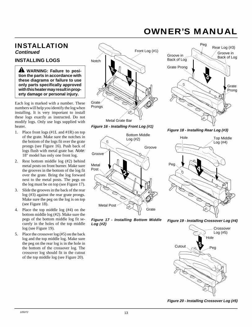
Figure 19 - Installing Crossover Log (#4)
Figure 18 - Installing Rear Log (#3)
CrossoverLog (#5)
Hole
PegCutout
Figure 20 - Installing Crossover Log (#5)
Bottom MiddleLog (#2)
Metal Post
MetalPost
Groove
Groove
Grate
Figure 17 - Installing Bottom MiddleLog (#2)
Figure 16 - Installing Front Log (#1)
GrateProngs
Metal Grate Bar
Front Log (#1)
Notch
WARNING: Failure to posi-tion the parts in accordance withthese diagrams or failure to useonly parts specifically approvedwith this heater may result in prop-erty damage or personal injury.
INSTALLING LOGS
INSTALLATIONContinued
Each log is marked with a number. Thesenumbers will help you identify the log wheninstalling. It is very important to installthese logs exactly as instructed. Do notmodify logs. Only use logs supplied withheater.
1. Place front logs (#1L and #1R) on topof the grate. Make sure the notches inthe bottom of the logs fit over the grateprongs (see Figure 16). Push back oflogs flush with metal grate bar. Note:18" model has only one front log.
2. Rest bottom middle log (#2) behindmetal posts on front burner. Make surethe grooves in the bottom of the log fitover the grate. Bring the log forwardnext to the metal posts. The pegs onthe log must be on top (see Figure 17).
3. Slide the grooves in the back of the rearlog (#3) against the rear grate prongs.Make sure the peg on the log is on top(see Figure 18).
4. Place the top middle log (#4) on thebottom middle log (#2). Make sure thepegs of the bottom middle log fit se-curely in the holes of the top middlelog (see Figure 19).
5. Place the crossover log (#5) on the backlog and the top middle log. Make surethe peg on the rear log is in the hole inthe bottom of the crossover log. Thecrossover log should fit in the cutoutof the top middle log (see Figure 20).
14 105072
UNVENTED NATURAL GAS LOG HEATER
FIREPLACE MANUFACTURERS INC.
OFF
PILOT ON
LO
IH AUTOOFFON
OPERATINGHEATER
FOR YOUR SAFETYREAD BEFORE
LIGHTING
WARNING: If you do not fol-low these instructions exactly, afire or explosion may result caus-ing property damage, personalinjury or loss of life.
A. This appliance has a pilot which mustbe lighted by hand. When lighting thepilot, follow these instructions exactly.
B. BEFORE LIGHTING smell allaround the appliance area for gas. Besure to smell next to the floor becausesome gas is heavier than air and willsettle on the floor.WHAT TO DO IF YOU SMELLGAS• Do not try to light any appliance.• Do not touch any electric switch; do
not use any phone in your building.• Immediately call your gas supplier
from a neighbor’s phone. Followthe gas supplier’s instructions.
• If you cannot reach your gas sup-plier, call the fire department.
C. Use only your hand to push in or turnthe gas control knob. Never use tools.If the knob will not push in or turnby hand, don’t try to repair it, call aqualified service technician or gassupplier. Force or attempted repairmay result in a fire or explosion.
D. Do not use this appliance if any parthas been under water. Immediatelycall a qualified service technician toinspect the appliance and to replaceany part of the control system andany gas control which has been un-der water.
LIGHTINGINSTRUCTIONS
WARNING• If fireplace has glass doors,
never operate this heater withglass doors closed. If you oper-ate heater with doors closed,heat buildup inside fireplace willcause glass to burst. Also iffireplace opening has vents atthe bottom, you must open thevents before operating heater.
• You must operate this heaterwith a fireplace screen in place.Make sure fireplace screen isclosed before running heater.
NOTICE: During initial operationof new heater, burning logs willgive off a paper-burning smell.Orange flame will also bepresent. Open damper or win-dow to vent smell. This will onlylast a few hours.
Note: Home owners generally prefer tooperate their heater with the chimneydamper closed. This will put all the heatinto the room. However, there may betimes you will desire the full flames of theHi heat setting but will find the heatoutput excessive. You can open the chim-ney damper (if you have one) fully orpartially to release some of the heat.
WARNING: Damper handle willbe hot if heater has been running.
WARNING: Burners will comeon automatically within oneminute when the selector switchis in the ON position after thepilot is lit.
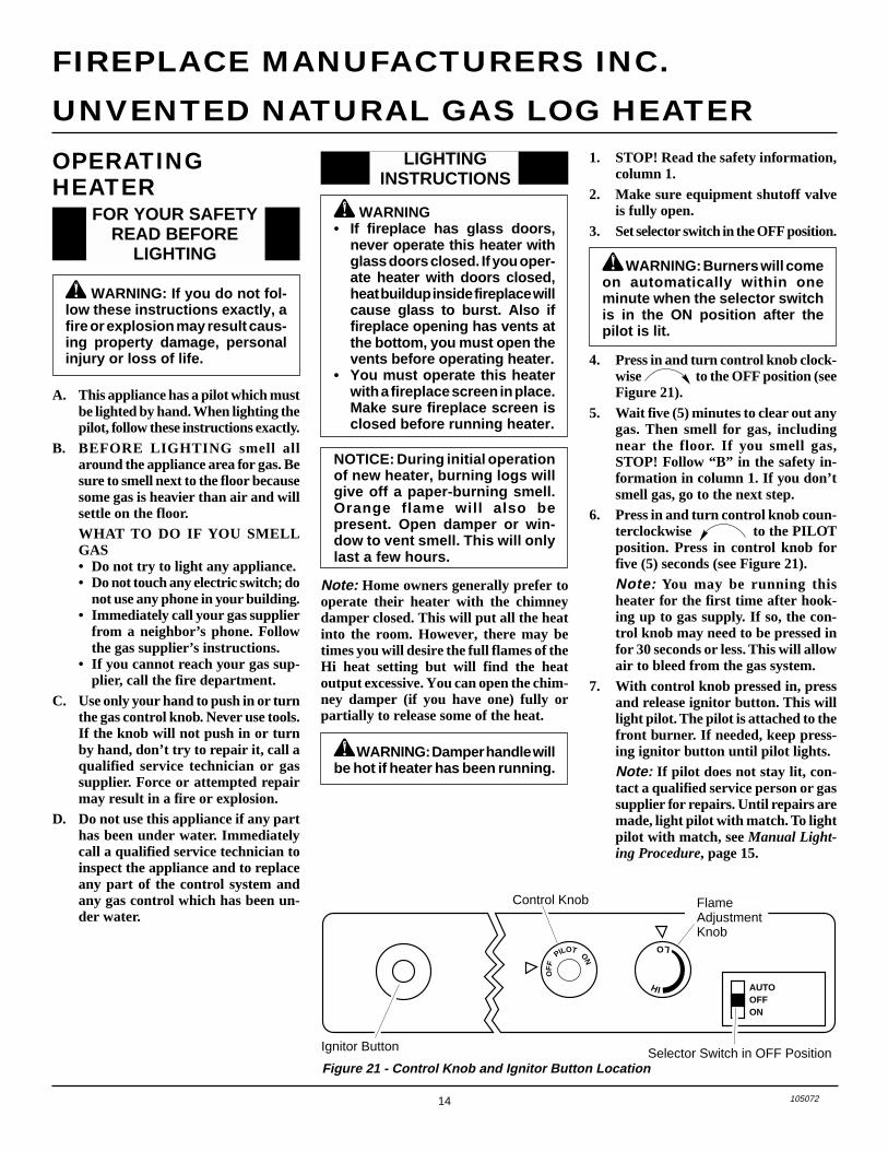
Figure 21 - Control Knob and Ignitor Button Location
Control Knob
4. Press in and turn control knob clock-wise to the OFF position (seeFigure 21).
5. Wait five (5) minutes to clear out anygas. Then smell for gas, includingnear the floor. If you smell gas,STOP! Follow “B” in the safety in-formation in column 1. If you don’tsmell gas, go to the next step.
6. Press in and turn control knob coun-terclockwise to the PILOTposition. Press in control knob forfive (5) seconds (see Figure 21).Note: You may be running thisheater for the first time after hook-ing up to gas supply. If so, the con-trol knob may need to be pressed infor 30 seconds or less. This will allowair to bleed from the gas system.
7. With control knob pressed in, pressand release ignitor button. This willlight pilot. The pilot is attached to thefront burner. If needed, keep press-ing ignitor button until pilot lights.Note: If pilot does not stay lit, con-tact a qualified service person or gassupplier for repairs. Until repairs aremade, light pilot with match. To lightpilot with match, see Manual Light-ing Procedure, page 15.
Selector Switch in OFF Position
FlameAdjustmentKnob
Ignitor Button
1. STOP! Read the safety information,column 1.
2. Make sure equipment shutoff valveis fully open.
3. Set selector switch in the OFF position.
15105072
OWNER’S MANUAL
OPERATINGHEATERContinued
TO TURN OFF GAS TOAPPLIANCE
1. Follow steps 1 through 6 under Light-ing Instructions, page 14.
2. Depress control knob and light pilotwith match.
3. Keep control knob pressed in for 30seconds after lighting pilot. After 30seconds, release control knob. Nowfollow steps 9 through 11, LightingInstructions, column 1.
Shutting Off Heater1. Turn control knob clockwise
to the OFF position.2a. Set selector switch in the OFF position.2b. If Using Optional Hand-Held Re-
mote: Set selector switch in the OFFposition to keep from draining battery.
Shutting Off Burners Only (pilotstays lit)
You may shut off the burners and keepthe pilot lit by doing one of the following:1. Turn control knob clockwise
to the PILOT position.2. Use remote control manual OFF
button.3. Set selector switch in the OFF position.
Continued
MANUAL LIGHTINGPROCEDURE
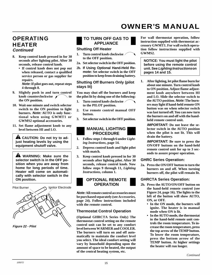
Ignitor ElectrodePilot Burner
Figure 22 - Pilot
9. Slightly push in and turn controlknob counterclockwise tothe ON position.
10. Wait one minute and switch selectorswitch to the ON position to lightburners. Note: AUTO is only func-tional when using GWMT1 orGWMS2 optional accessories.
11. Set flame adjustment knob to anylevel between HI and LO.
CAUTION: Do not try to ad-just heating levels by using theequipment shutoff valve.
8. Keep control knob pressed in for 30seconds after lighting pilot. After 30seconds, release control knob.• If control knob does not pop out
when released, contact a qualifiedservice person or gas supplier forrepairs.Note: If pilot goes out, repeat steps4 through 8.
WARNING: Make sure theselector switch is in the OFF po-sition when you are away fromhome for long periods of time.Heater will come on automati-cally with selector switch in theON position.
Note: All remote control accessories mustbe purchased separately (see Accessories,page 24). Follow instructions includedwith the remote control.
Thermostat Control Operation
(Optional GHRCTA Series Only) Thethermostat control setting on the remotecontrol unit can be set to any comfortlevel between WARMER and COOLER.The burners will turn on and off auto-matically to maintain the comfort levelyou select. The ideal comfort setting willvary by household depending upon theamount of space to be heated, the outputof the central heating system, etc.
OPTIONAL REMOTEOPERATION
NOTICE: You must light the pilotbefore using the remote controlunit. See Lighting Instructions onpages 14 and 15.
For wall thermostat operation, followinstruction supplied with thermostat ac-cessory GWMT1. For wall switch opera-tion follow instructions supplied withGWMS2.
1. After lighting, let pilot flame burn forabout one minute. Turn control knobto ON position. Adjust flame adjust-ment knob anywhere between HIand LO. Slide the selector switch tothe AUTO position. Note: The burn-ers may light if hand-held remote ONbutton was on when selector switchwas last turned off. You can now turnthe burners on and off with the hand-held remote control unit.IMPORTANT: Do not leave the se-lector switch in the AUTO positionwhen the pilot is not lit. This willdrain the battery.IMPORTANT: Be sure to press theON/OFF buttons on the hand-heldremote control unit for up to 3 sec-onds to assure proper operation.
GHRC Series Operation:2a. Press the ON/OFF button to turn the
burners on and off. When turningburners off, the pilot will remain lit.
GHRCTA Series Operation:2b. Press the AUTO/ON/OFF button on
the hand-held remote control (seeFigure 24, page 16). The lights to theleft of the button will show AUTO,ON, or OFF.• In the ON mode, the burners will
ignite. The heater is in manualmode when ON is lit.
• In the AUTO mode, the thermostatin the hand-held remote unit con-trols the room temperature. To in-crease the room temperature, pressthe top arrow of the TEMP button.To lower the room temperature,press the bottom arrow of theTEMP button. At higher settingsthe heater will run longer.
16 105072
UNVENTED NATURAL GAS LOG HEATER
FIREPLACE MANUFACTURERS INC.
ThermocouplePilot Burner
Figure 25 - Correct Pilot Flame Pattern
Figure 26 - Incorrect Pilot Flame Pattern
INSPECTINGBURNERSCheck pilot flame pattern and burner flamepatterns often.
PILOT FLAME PATTERNFigure 25 shows a correct pilot flame pat-tern. Figure 26 shows an incorrect pilotflame pattern. The incorrect pilot flame isnot touching the thermocouple. This willcause the thermocouple to cool. When thethermocouple cools, the heater will shutdown.
If pilot flame pattern is incorrect, as shownin Figure 26
• turn heater off (see To Turn Off Gas toAppliance, page 15)
• see Troubleshooting, pages 18 through 20
ThermocouplePilot Burner
OPERATINGHEATERContinued
Figure 23 - Setting the Remote Selector Switch, Control Knob, and Flame AdjustmentKnob for Remote Operation
OFF
PILOT
ON
LO
IH ONOFFREMOTE
Selector Switch inRemote Position
Control Knob inOn Position Flame Adjustment Knob
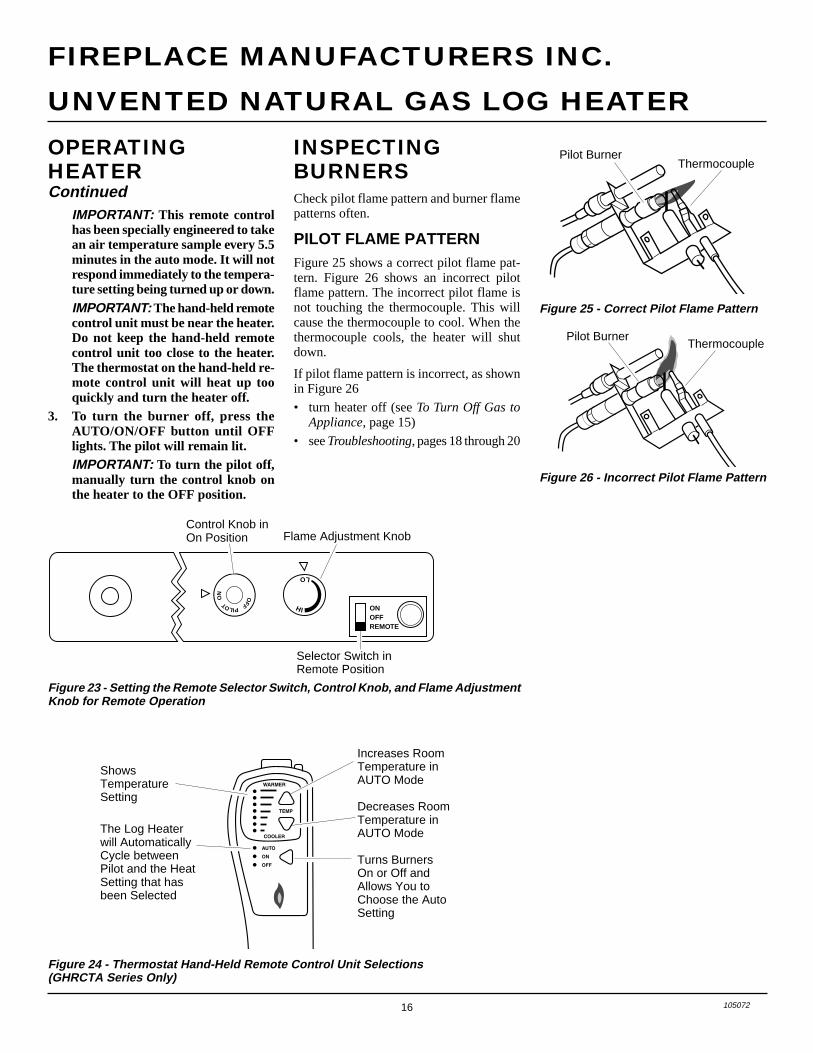
Figure 24 - Thermostat Hand-Held Remote Control Unit Selections(GHRCTA Series Only)
Increases RoomTemperature inAUTO Mode
Decreases RoomTemperature inAUTO Mode
Turns BurnersOn or Off andAllows You toChoose the AutoSetting
ShowsTemperatureSetting
The Log Heaterwill AutomaticallyCycle betweenPilot and the HeatSetting that hasbeen Selected
IMPORTANT: This remote controlhas been specially engineered to takean air temperature sample every 5.5minutes in the auto mode. It will notrespond immediately to the tempera-ture setting being turned up or down.IMPORTANT: The hand-held remotecontrol unit must be near the heater.Do not keep the hand-held remotecontrol unit too close to the heater.The thermostat on the hand-held re-mote control unit will heat up tooquickly and turn the heater off.
3. To turn the burner off, press theAUTO/ON/OFF button until OFFlights. The pilot will remain lit.IMPORTANT: To turn the pilot off,manually turn the control knob onthe heater to the OFF position.
17105072
OWNER’S MANUAL
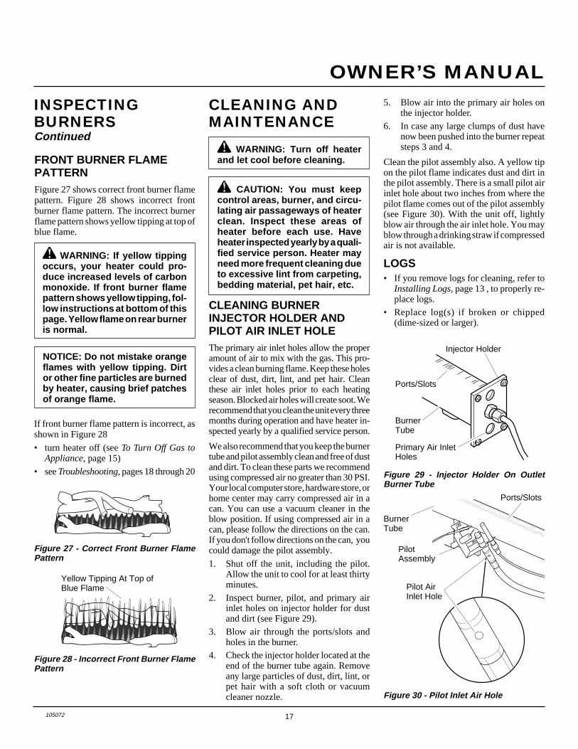
WARNING: If yellow tippingoccurs, your heater could pro-duce increased levels of carbonmonoxide. If front burner flamepattern shows yellow tipping, fol-low instructions at bottom of thispage. Yellow flame on rear burneris normal.
Figure 28 - Incorrect Front Burner FlamePattern
Figure 27 - Correct Front Burner FlamePattern
Yellow Tipping At Top ofBlue Flame
FRONT BURNER FLAMEPATTERNFigure 27 shows correct front burner flamepattern. Figure 28 shows incorrect frontburner flame pattern. The incorrect burnerflame pattern shows yellow tipping at top ofblue flame.
NOTICE: Do not mistake orangeflames with yellow tipping. Dirtor other fine particles are burnedby heater, causing brief patchesof orange flame.
If front burner flame pattern is incorrect, asshown in Figure 28
• turn heater off (see To Turn Off Gas toAppliance, page 15)
• see Troubleshooting, pages 18 through 20
CLEANING ANDMAINTENANCE
WARNING: Turn off heaterand let cool before cleaning.
CAUTION: You must keepcontrol areas, burner, and circu-lating air passageways of heaterclean. Inspect these areas ofheater before each use. Haveheater inspected yearly by a quali-fied service person. Heater mayneed more frequent cleaning dueto excessive lint from carpeting,bedding material, pet hair, etc.
CLEANING BURNERINJECTOR HOLDER ANDPILOT AIR INLET HOLEThe primary air inlet holes allow the properamount of air to mix with the gas. This pro-vides a clean burning flame. Keep these holesclear of dust, dirt, lint, and pet hair. Cleanthese air inlet holes prior to each heatingseason. Blocked air holes will create soot. Werecommend that you clean the unit every threemonths during operation and have heater in-spected yearly by a qualified service person.
We also recommend that you keep the burnertube and pilot assembly clean and free of dustand dirt. To clean these parts we recommendusing compressed air no greater than 30 PSI.Your local computer store, hardware store, orhome center may carry compressed air in acan. You can use a vacuum cleaner in theblow position. If using compressed air in acan, please follow the directions on the can.If you don't follow directions on the can, youcould damage the pilot assembly.
1. Shut off the unit, including the pilot.Allow the unit to cool for at least thirtyminutes.
2. Inspect burner, pilot, and primary airinlet holes on injector holder for dustand dirt (see Figure 29).
3. Blow air through the ports/slots andholes in the burner.
4. Check the injector holder located at theend of the burner tube again. Removeany large particles of dust, dirt, lint, orpet hair with a soft cloth or vacuumcleaner nozzle.
5. Blow air into the primary air holes onthe injector holder.
6. In case any large clumps of dust havenow been pushed into the burner repeatsteps 3 and 4.
Clean the pilot assembly also. A yellow tipon the pilot flame indicates dust and dirt inthe pilot assembly. There is a small pilot airinlet hole about two inches from where thepilot flame comes out of the pilot assembly(see Figure 30). With the unit off, lightlyblow air through the air inlet hole. You mayblow through a drinking straw if compressedair is not available.
Figure 29 - Injector Holder On OutletBurner Tube
BurnerTube
PilotAssembly
Pilot AirInlet Hole
Ports/Slots
Figure 30 - Pilot Inlet Air Hole
LOGS• If you remove logs for cleaning, refer to
Installing Logs, page 13 , to properly re-place logs.
• Replace log(s) if broken or chipped(dime-sized or larger).
INSPECTINGBURNERSContinued
BurnerTube
Injector Holder
Primary Air InletHoles
Ports/Slots
18 105072
UNVENTED NATURAL GAS LOG HEATER
FIREPLACE MANUFACTURERS INC.
WARNING: Turn off and un-plug heater and let cool beforeservicing. Only a qualified ser-vice person should service andrepair heater.
CAUTION: Never use a wire,needle, or similar object to cleanODS/pilot. This can damage ODS/pilot unit.
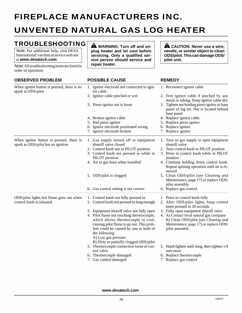
POSSIBLE CAUSE
1. Ignitor electrode not connected to igni-tor cable
2. Ignitor cable pinched or wet
3. Piezo ignitor nut is loose
4. Broken ignitor cable5. Bad piezo ignitor6. Ignitor electrode positioned wrong7. Ignitor electrode broken
1. Gas supply turned off or equipmentshutoff valve closed
2. Control knob not in PILOT position3. Control knob not pressed in while in
PILOT position4. Air in gas lines when installed
5. ODS/pilot is clogged
6. Gas control setting is not correct
1. Control knob not fully pressed in2. Control knob not pressed in long enough
3. Equipment shutoff valve not fully open4. Pilot flame not touching thermocouple,
which allows thermocouple to cool,causing pilot flame to go out. This prob-lem could be caused by one or both ofthe following:A) Low gas pressureB) Dirty or partially clogged ODS/pilot
5. Thermocouple connection loose at con-trol valve
6. Thermocouple damaged7. Gas control damaged
OBSERVED PROBLEM
When ignitor button is pressed, there is nospark at ODS/pilot
When ignitor button is pressed, there isspark at ODS/pilot but no ignition
ODS/pilot lights but flame goes out whencontrol knob is released
TROUBLESHOOTING
REMEDY
1. Reconnect ignitor cable
2. Free ignitor cable if pinched by anymetal or tubing. Keep ignitor cable dry
3. Tighten nut holding piezo ignitor to basepanel of log set. Nut is located behindbase panel
4. Replace ignitor cable5. Replace piezo ignitor6. Replace ignitor7. Replace ignitor
1. Turn on gas supply or open equipmentshutoff valve
2. Turn control knob to PILOT position3. Press in control knob while in PILOT
position4. Continue holding down control knob.
Repeat igniting operation until air is re-moved
5. Clean ODS/pilot (see Cleaning andMaintenance, page 17) or replace ODS/pilot assembly
6. Replace gas control
1. Press in control knob fully2. After ODS/pilot lights, keep control
knob pressed in 30 seconds3. Fully open equipment shutoff valve4. A) Contact local natural gas company
B) Clean ODS/pilot (see Cleaning andMaintenance, page 17) or replace ODS/pilot assembly
5. Hand tighten until snug, then tighten 1/4turn more
6. Replace thermocouple7. Replace gas control
Note: For additional help, visit DESAInternational’s technical service web siteat www.desatech.com.
Note: All troubleshooting items are listed inorder of operation.
www.desatech.com
19105072
OWNER’S MANUAL
TROUBLESHOOTINGContinued
Continued
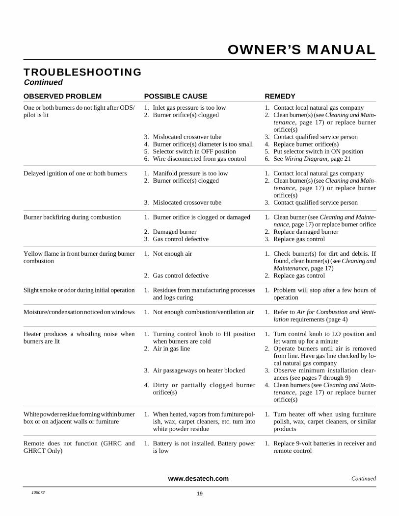
REMEDY
1. Contact local natural gas company2. Clean burner(s) (see Cleaning and Main-
tenance, page 17) or replace burnerorifice(s)
3. Contact qualified service person4. Replace burner orifice(s)5. Put selector switch in ON position6. See Wiring Diagram, page 21
1. Contact local natural gas company2. Clean burner(s) (see Cleaning and Main-
tenance, page 17) or replace burnerorifice(s)
3. Contact qualified service person
1. Clean burner (see Cleaning and Mainte-nance, page 17) or replace burner orifice
2. Replace damaged burner3. Replace gas control
1. Check burner(s) for dirt and debris. Iffound, clean burner(s) (see Cleaning andMaintenance, page 17)
2. Replace gas control
1. Problem will stop after a few hours ofoperation
1. Refer to Air for Combustion and Venti-lation requirements (page 4)
1. Turn control knob to LO position andlet warm up for a minute
2. Operate burners until air is removedfrom line. Have gas line checked by lo-cal natural gas company
3. Observe minimum installation clear-ances (see pages 7 through 9)
4. Clean burners (see Cleaning and Main-tenance, page 17) or replace burnerorifice(s)
1. Turn heater off when using furniturepolish, wax, carpet cleaners, or similarproducts
1. Replace 9-volt batteries in receiver andremote control
OBSERVED PROBLEM
One or both burners do not light after ODS/pilot is lit
Delayed ignition of one or both burners
Burner backfiring during combustion
Yellow flame in front burner during burnercombustion
Slight smoke or odor during initial operation
Moisture/condensation noticed on windows
Heater produces a whistling noise whenburners are lit
White powder residue forming within burnerbox or on adjacent walls or furniture
Remote does not function (GHRC andGHRCT Only)
POSSIBLE CAUSE
1. Inlet gas pressure is too low2. Burner orifice(s) clogged
3. Mislocated crossover tube4. Burner orifice(s) diameter is too small5. Selector switch in OFF position6. Wire disconnected from gas control
1. Manifold pressure is too low2. Burner orifice(s) clogged
3. Mislocated crossover tube
1. Burner orifice is clogged or damaged
2. Damaged burner3. Gas control defective
1. Not enough air
2. Gas control defective
1. Residues from manufacturing processesand logs curing
1. Not enough combustion/ventilation air
1. Turning control knob to HI positionwhen burners are cold
2. Air in gas line
3. Air passageways on heater blocked
4. Dirty or partially clogged burnerorifice(s)
1. When heated, vapors from furniture pol-ish, wax, carpet cleaners, etc. turn intowhite powder residue
1. Battery is not installed. Battery poweris low
www.desatech.com

20 105072
UNVENTED NATURAL GAS LOG HEATER
FIREPLACE MANUFACTURERS INC.
REMEDY
1. This is common with most heaters. Ifnoise is excessive, contact qualified ser-vice person
1. Open window to ventilate room. Stop us-ing odor causing products while heateris running
2. Refill supply tank3. Locate and correct all leaks (see Check-
ing Gas Connections, page 12)
1. Open window and/or door for ventilation2. Contact local natural gas company3. Clean ODS/pilot (see Cleaning and
Maintenance, page 17)
1. Locate and correct all leaks (see Check-ing Gas Connections, page 12)
2. Replace gas control
1. Take apart gas tubing and remove for-eign matter
2. Locate and correct all leaks (see Check-ing Gas Connections, page 12)
1. Move hand-held remote control unit far-ther away from the heater
WARNING: If you smell gas• Shut off gas supply.• Do not try to light any appliance.• Do not touch any electrical switch; do not use any phone in your
building.• Immediately call your gas supplier from a neighbor’s phone. Follow the
gas supplier’s instructions.• If you cannot reach your gas supplier, call the fire department.
POSSIBLE CAUSE
1. Metal expanding while heating or con-tracting while cooling
1. Heater burning vapors from paint, hairspray, glues, cleaners, chemicals, newcarpet, etc. (See IMPORTANT state-ment above)
2. Low fuel supply3. Gas leak. See Warning statement
above
1. Not enough fresh air is available2. Low line pressure3. ODS/pilot is partially clogged
1. Gas leak. See Warning statementabove
2. Gas control defective
1. Foreign matter between control valveand burner
2. Gas leak. See Warning statementabove
1. Hand-held remote control unit needs tobe moved away from heater
OBSERVED PROBLEM
Heater produces a clicking/ticking noisejust after burners are lit or shut off
Heater produces unwanted odors
Heater shuts off in use (ODS operates)
Gas odor even when control knob is in OFFposition
Gas odor during combustion
Log set cycles to pilot, but room tempera-ture drops to a lower than ideal level beforelog set comes back on (GHRCT Only)
TROUBLESHOOTINGContinued
IMPORTANT: Operating heater where impurities in air exist may create odors. Cleaningsupplies, paint, paint remover, cigarette smoke, cements and glues, new carpet or textiles,etc., create fumes. These fumes may mix with combustion air and create odors. These odorswill disappear over time.
www.desatech.com
21105072
OWNER’S MANUAL
REPLACEMENTPARTSNote: Use only original replacement parts.This will protect your warranty coverage forparts replaced under warranty.
PARTS UNDER WARRANTYContact authorized dealers of this product.If they can’t supply original replacementpart(s), call Fireplace ManufacturersIncorporated's Technical Service Depart-ment at 1-888-427-8322.
When calling Fireplace Manufacturers Inc.,have ready
• your name and address
• model and serial numbers of your heater
• how heater was malfunctioning
• type of gas used (propane/LP or natural gas)
• purchase date
Usually, we will ask you to return the defec-tive part to the factory.
PARTS NOT UNDERWARRANTYContact authorized dealers of this product.If they can’t supply original replacementpart(s), call Fireplace ManufacturersIncorporated's Parts Department at 1-800-888-2050 for referral information.
When calling Fireplace Manufacturers Inc.,have ready
• model number of your heater
• the replacement part number
TECHNICALSERVICEYou may have further questions about in-stallation, operation, or troubleshooting. Ifso, contact Fireplace ManufacturersIncorporated's Technical Service Depart-ment at 1-888-427-8322.
You can also visit DESA International’stechnical services web site atwww.desatech.com.
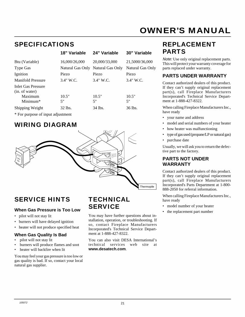
SPECIFICATIONS18" Variable 24" Variable 30" Variable
Btu (Variable) 16,000/26,000 20,000/33,000 21,5000/36,000
Type Gas Natural Gas Only Natural Gas Only Natural Gas Only
Ignition Piezo Piezo Piezo
Manifold Pressure 3.4" W.C. 3.4" W.C. 3.4" W.C.
Inlet Gas Pressure(in. of water)
Maximum 10.5" 10.5" 10.5"Minimum* 5" 5" 5"
Shipping Weight 32 lbs. 34 lbs. 36 lbs.
* For purpose of input adjustment
WIRING DIAGRAM
SERVICE HINTSWhen Gas Pressure is Too Low• pilot will not stay lit
• burners will have delayed ignition
• heater will not produce specified heat
When Gas Quality Is Bad• pilot will not stay lit• burners will produce flames and soot• heater will backfire when lit
You may feel your gas pressure is too low orgas quality is bad. If so, contact your localnatural gas supplier.
AUTOOFFON
Thermopile
22 105072
UNVENTED NATURAL GAS LOG HEATER
FIREPLACE MANUFACTURERS INC.
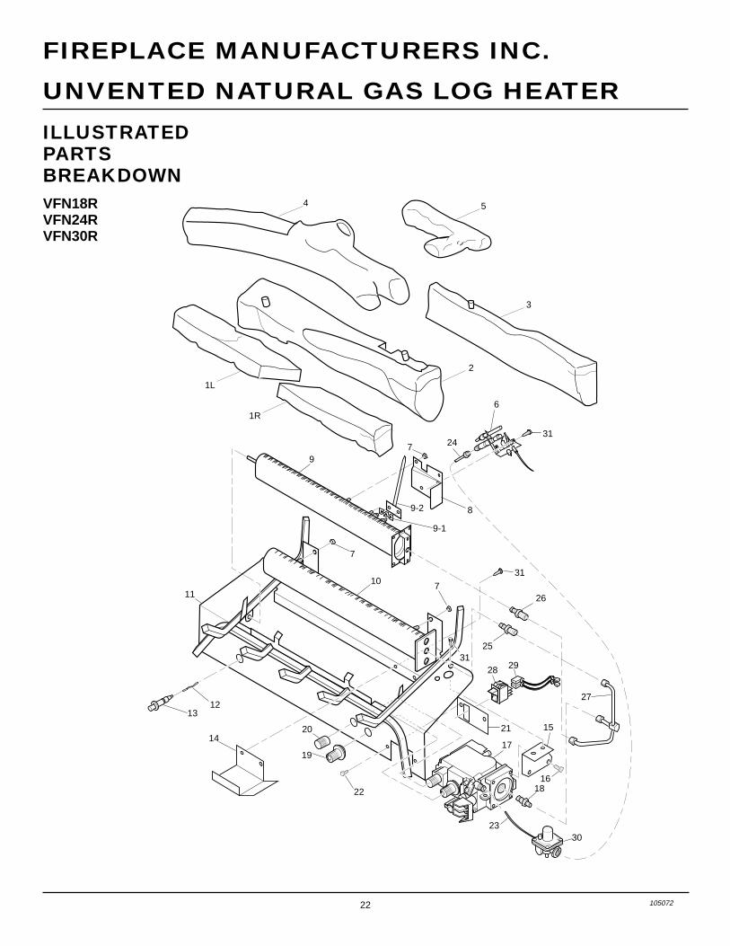
ILLUSTRATEDPARTSBREAKDOWNVFN18RVFN24RVFN30R
7
8
9
10
7
711
12
22
13
25
26
31
31
15
18
30
20 21
28 29
16
23
19
14
27
17
9-1
9-2
31
6
24
2
1R
1L
3
54
23105072
OWNER’S MANUAL
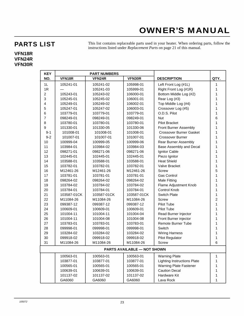
PARTS LISTVFN18RVFN24RVFN30R
This list contains replaceable parts used in your heater. When ordering parts, follow theinstructions listed under Replacement Parts on page 21 of this manual.
KEY PART NUMBERSNO. VFN18R VFN24R VFN30R DESCRIPTION QTY.
1L 105241-01 105241-02 105998-01 Left Front Log (#1L) 11R — 105241-03 105999-01 Right Front Log (#1R) 12 105243-01 105243-02 106000-01 Bottom Middle Log (#2) 13 105245-01 105245-02 106001-01 Rear Log (#3) 14 105249-01 105249-02 106002-01 Top Middle Log (#4) 15 105247-01 105247-02 106003-01 Crossover Log (#5) 16 103779-01 103779-01 103779-01 O.D.S. Pilot 17 098249-01 098249-01 098249-01 Nut 68 103780-01 103780-01 103780-01 Pilot Bracket 19 101330-01 101330-05 101330-06 Front Burner Assembly 1 9-1 101008-01 101008-01 101008-01 Crossover Burner Gasket 1 9-2 101007-01 101007-01 101007-01 Crossover Burner 110 100999-04 100999-05 100999-06 Rear Burner Assembly 111 103984-01 103984-02 103984-03 Base Assembly and Decal 112 098271-01 098271-06 098271-06 Ignitor Cable 113 102445-01 102445-01 102445-01 Piezo Ignitor 114 103588-01 103588-01 103588-01 Heat Shield 115 103782-01 103782-01 103782-01 Valve Bracket 116 M12461-26 M12461-26 M12461-26 Screw 517 103781-01 103781-01 103781-01 Gas Control 118 098264-02 098264-02 098264-02 Male Fitting 119 103784-02 103784-02 103784-02 Flame Adjustment Knob 120 103784-01 103784-01 103784-01 Control Knob 121 103587-01CK 103587-01CK 103587-01CK Switch Plate 122 M11084-26 M11084-26 M11084-26 Screw 223 099387-12 099387-12 099387-12 Pilot Tube 124 100609-01 100609-01 100609-01 Pilot Tube 125 101004-11 101004-11 101004-04 Read Burner Injector 126 101004-11 101004-08 101004-08 Front Burner injector 127 103783-01 103783-01 103783-01 Remote Burner Tube 128 099998-01 099998-01 099998-01 Switch 129 103284-02 103284-02 103284-02 Wiring Harness 130 099918-02 099918-02 099918-02 Pilot Regulator 131 M11084-26 M11084-26 M11084-26 Screw 6
PARTS AVAILABLE — NOT SHOWN
100563-01 100563-01 100563-01 Warning Plate 1103877-01 103877-01 103877-01 Lighting Instructions Plate 1100565-01 100565-01 100565-01 Warning Plate Fastener 1100639-01 100639-01 100639-01 Caution Decal 1101137-02 101137-02 101137-02 Hardware Kit 1GA6060 GA6060 GA6060 Lava Rock 1
24 105072
UNVENTED NATURAL GAS LOG HEATER
FIREPLACE MANUFACTURERS INC.
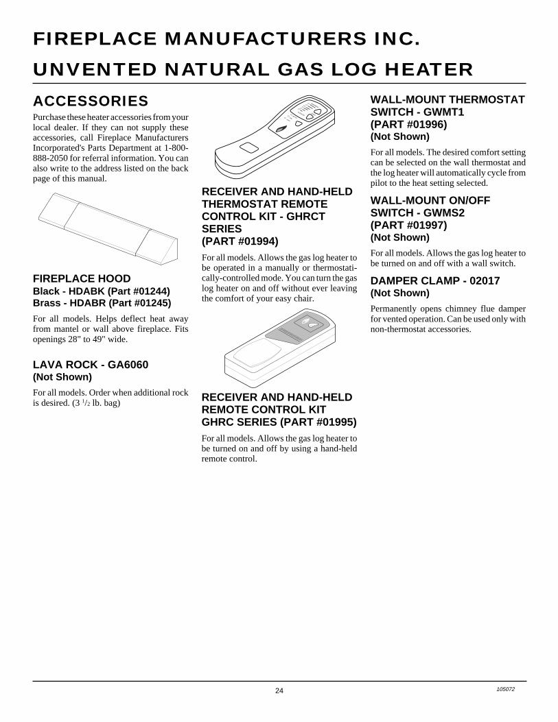
Purchase these heater accessories from yourlocal dealer. If they can not supply theseaccessories, call Fireplace ManufacturersIncorporated's Parts Department at 1-800-888-2050 for referral information. You canalso write to the address listed on the backpage of this manual.
FIREPLACE HOODBlack - HDABK (Part #01244)Brass - HDABR (Part #01245)
For all models. Helps deflect heat awayfrom mantel or wall above fireplace. Fitsopenings 28" to 49" wide.
LAVA ROCK - GA6060(Not Shown)
For all models. Order when additional rockis desired. (3 1/2 lb. bag)
ACCESSORIESAUTOON
OFF
COOLER
WARMER
TEMP
RECEIVER AND HAND-HELDTHERMOSTAT REMOTECONTROL KIT - GHRCTSERIES(PART #01994)For all models. Allows the gas log heater tobe operated in a manually or thermostati-cally-controlled mode. You can turn the gaslog heater on and off without ever leavingthe comfort of your easy chair.
RECEIVER AND HAND-HELDREMOTE CONTROL KITGHRC SERIES (PART #01995)For all models. Allows the gas log heater tobe turned on and off by using a hand-heldremote control.
WALL-MOUNT THERMOSTATSWITCH - GWMT1(PART #01996)(Not Shown)
For all models. The desired comfort settingcan be selected on the wall thermostat andthe log heater will automatically cycle frompilot to the heat setting selected.
WALL-MOUNT ON/OFFSWITCH - GWMS2(PART #01997)(Not Shown)
For all models. Allows the gas log heater tobe turned on and off with a wall switch.
DAMPER CLAMP - 02017(Not Shown)
Permanently opens chimney flue damperfor vented operation. Can be used only withnon-thermostat accessories.
25105072
OWNER’S MANUAL
NOTES_______________________________________________________________________________________________
_______________________________________________________________________________________________
_______________________________________________________________________________________________
_______________________________________________________________________________________________
_______________________________________________________________________________________________
_______________________________________________________________________________________________
_______________________________________________________________________________________________
_______________________________________________________________________________________________
_______________________________________________________________________________________________
_______________________________________________________________________________________________
_______________________________________________________________________________________________
_______________________________________________________________________________________________
_______________________________________________________________________________________________
_______________________________________________________________________________________________
_______________________________________________________________________________________________
_______________________________________________________________________________________________
_______________________________________________________________________________________________
_______________________________________________________________________________________________
_______________________________________________________________________________________________
_______________________________________________________________________________________________
_______________________________________________________________________________________________
_______________________________________________________________________________________________
_______________________________________________________________________________________________
_______________________________________________________________________________________________
_______________________________________________________________________________________________
_______________________________________________________________________________________________
_______________________________________________________________________________________________
_______________________________________________________________________________________________
_______________________________________________________________________________________________
_______________________________________________________________________________________________
_______________________________________________________________________________________________
_______________________________________________________________________________________________
_______________________________________________________________________________________________
_______________________________________________________________________________________________
LIMITED WARRANTYVENT-FREE NATURAL GAS LOG HEATERS
DESA International warrants this product to be free from defects in materials and components for one (1) year from the date of firstpurchase, provided that the product has been properly installed, operated and maintained in accordance with all applicable instructions.There is no warranty on the batteries. To make a claim under this warranty the Bill of Sale or cancelled check must be presented.
This warranty is extended only to the original retail purchaser. This warranty covers the cost of part(s) required to restore this heaterto proper operating condition and an allowance for labor when provided by a DESA International Authorized Service Center. Warrantypart(s) MUST be obtained through authorized dealers of this product and/or DESA International who will provide original factoryreplacement parts. Failure to use original factory replacement parts voids this warranty. The heater MUST be installed by a qualifiedinstaller in accordance with all local codes and instructions furnished with the unit.
This warranty does not apply to parts that are not in original condition because of normal wear and tear, or parts that fail or becomedamaged as a result of misuse, accidents, lack of proper maintenance or defects caused by improper installation. Travel, diagnostic cost,labor, transportation and any and all such other costs related to repairing a defective heater will be the responsibility of the owner.
TO THE FULL EXTENT ALLOWED BY THE LAW OF THE JURISDICTION THAT GOVERNS THE SALE OF THE PRODUCT;THIS EXPRESS WARRANTY EXCLUDES ANY AND ALL OTHER EXPRESSED WARRANTIES AND LIMITS THE DURA-TION OF ANY AND ALL IMPLIED WARRANTIES, INCLUDING WARRANTIES OF MERCHANTABILITY AND FITNESSFOR A PARTICULAR PURPOSE TO ONE (1) YEAR ON ALL COMPONENTS FROM THE DATE OF FIRST PURCHASE; ANDDESA INTERNATIONAL'S LIABILITY IS HEREBY LIMITED TO THE PURCHASE PRICE OF THE PRODUCT AND DESAINTERNATIONAL SHALL NOT BE LIABLE FOR ANY OTHER DAMAGES WHATSOEVER INCLUDING INDIRECT,INCIDENTAL OR CONSEQUENTIAL DAMAGES.
Some states do not allow a limitation on how long an implied warranty lasts or an exclusion or limitation of incidental or consequentialdamages, so the above limitation on implied warranties, or exclusion or limitation on damages may not apply to you.
This warranty gives you specific legal rights, and you may also have other rights that vary from state to state.
For information about this warranty write:
KEEP THIS WARRANTY
WARRANTY INFORMATION
Model
Serial No.
Date Purchased
Always specify model and serial numbers when communicating with the factory.
We reserve the right to amend these specifications at any time without notice. The only warranty applicable is our standard writtenwarranty. We make no other warranty, expressed or implied.
105072-01Rev. F11/01NOT A UPC
105072 01
2701 Industrial DriveP.O. Box 90004Bowling Green, KY 42102-9004
www.desatech.com
INTERNATIONAL