Embed Size (px)
Citation preview
Nov. 4 , 1924. 1,514,136 7 J. H. WIGGINS
OIL STORAGE TANK
Filed May 19, 71922 4 Sheets-Sheet 1
I N VENTOR‘
John \AL/QQ

T Nov. 4 , 1924.. J. H. WIGGINS
OIL STORAGE TANK
Filed May 19 , 1922
1,514,116 ‘
4 Sheets-Sheet 2
Nuv. 4 , 1924. 1,514,116 J. H. WIGGINS
OIL STORAGE _ TANK
Filed May 19, 1.9?2 4 Sheets-Sheet 5
" 0 0
dohn f7 Mag/27s r/? g 2 BY ‘4/:
? TTORNEYS
1,514,116 , 1924. Nov. 4 J. H. WIGGINS
OIL STORAGE TANK
Filed May 19, 1922 4 Sheets-Sheet 4
& [NVLTNTOR duh/1 f1 Mag/n5

10
15
20
25
30
45
50
Patented Nov, 4, 1924.
s'rATEs
i,514,ne rarsur orri'cs;
JOHN H. ‘WIGGI'NS, OF BARTLESVILLE, OKLAHOMA.
OIL-STORAGE TANK.
Application ?led May 19, 1922. gel-m1 N0. 562,19‘?°
To all whom it‘ may concern: Be it known that 1, Joan H. Wrccms, a
citizen of the United States, residing at Bartlesville, Oklahoma, have invented _a certain new and useful Improvement in Oil Storage Tanks, of which the following is a full, clear, and exact description, such as will enable others skilled in the art to which it appertains to make and use the same. This invention relates to oil storage tanks
of the type in which the top or deck of the tank is not connected to the side wall of the tank, but normally ?oats upon and is sup ported by the oil in the tank. One object of my present invention is to
provide an- oil storage tank, of the general type referred to having a cylindrical side wall that is effectively braced against wind pressure and maintained in circular shape by tension members that extend trans versely of the tank above the upper edge ofsame. Another object is to provide an oil stor
age tank of the general type referred to which is ‘of such construction that its full. capacity can be utilized at all times. Another object is to provide a novel
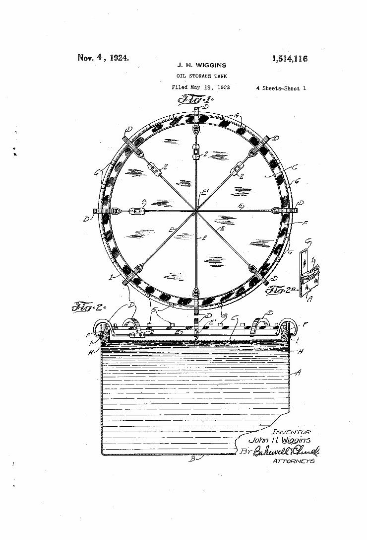
closure for the annular Space between the periphery of the ?oating deck and the side wall of the tank, that is ?re-proof, prac tically air-tight and of such construction that it provides for variations in the rela tive position of the deck and side wall caused by expansion and contraction of the metal from which said elements are formed. Other objects and desirable features of my invention will be hereinafter pointed out. Figure 1 of the drawings is a top plan
view of an oil storage tank constructed in accordance with my invention. Figure 2 is a vertical transverse sectional
view‘ of the tank shown in Figure 1. , Figure 2a is a detail perspective view,_ il
lustrating one of the upwardly-projecting guides at the upper edge of the side wall of, the tank ‘that co-operate with the shoe.
Figure 3 is a top plan view, partly broken away, illustrating another form of my in vention. ' p ' _
Figure 4 is a vertical transverse sectional view of the tank shown in Figure 3.
Figures 4a and 4:“ are detail- sectional I views of the tankshown in Figure 4.
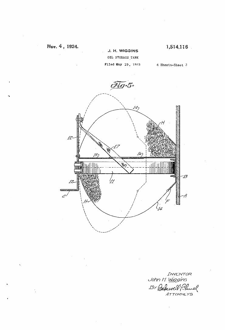
55 Figure 5 is an enlarged detail view in‘ ver-'
tical transverse section, illustrating the
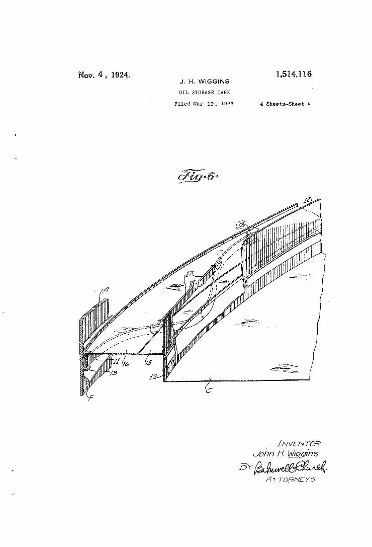
means that I prefer to use for closing the annular space between the periphery of the deck and the side wall of the tank; and Figure 6 is an enlarged perspective view,
illustrating one of the leaf springs that is 60 used to support the shoe and hold it pressed ' against the side wall of the tank. Referring to Figures 1 and 2 of the draw
ings which illustrate one form of my in vention, A designates a cylindrical, vertical~ ly-disposed vshell that forms the side wall of an oil storage tank, B designates the bottom of said tank and C designates the top or deck of the tank which normally ?oats upon and is supported by the oil in the tank. In order to brace the side wall A against wind pressure and maintain said side wall in circular shape, I have equipped the tank with a number of ‘devices D con nected to the upper edge of the side wall and joined together by tension rods E that extend transversely across the tank, the de
65
70
75
vices D being preferably connected to a _ horizontally-disposed ?ange formed by an angle 1 that extends around the upper edge of the side wall A, and said devices D be ing arranged in pairs disposed diametrical ly opposite each other, and each pair of devices being connected together by one of the tension rods E. If desired, the ten sion rods E can be provided with turn buckles or other suitable devices 2 for in creasing or decreasing the length of said rods, so as to vary,the length of same, and a center ring E’ can be provided through which the tension rods pass and from which said tension rods project radially. The rods E maintain the side wall A of the tank in a truly circular shape, and they effective ly brace the side wall against wind pressure by reason of the fact that said rods and the devices D with which they co-operate are combined with the side wall vA of the tank in such a way that said side wallpis di vided. into a number of relatively small arches.‘ Means is provided for closing the annular space between the periphery of the .deck C and the side wall of the tank, and while the particular construction-of said means is immaterial, so far as the'bracingi of the side wall is. concerned, said‘ means usually , comprise a I substantially-wring shaped shoe F arranged in slidinglengag'e-? ' ment? withthe'inner face o'fithe side-wallv ’ ' A, and" supported by the deck such-a
80
85
90
as
100
105' ;
no

10V
16
20
25
30
85
40
60
Q 1,514,116
way that it will rise and fall with said deck 'as the level of the oil in the tank varies. In order that the full capacity of the tank vmay be used at all times means is provided for enabling the shoe F to move upwardly above the top edge of said side wall when the tank is full or substantially so with out interfering with the tension members that extend transversely across the tank. In the form of my invention illustrated in Figures ,1 and 2, this is accomplished by using devices D of substantially C-shape in general form and providing the side wall A with vertically-disposed guides G that project upwardly above the top edge of said side wall, and thus act as guides against which the shoe F bears when the tank A is substantially full, or, in other words, when the oil in the tank is at such a level that the shoe F extends above the upper edge of the side wall A. The guides G are arranged in spaced relation around the upper edge of the side wall A, and the C-shaped devices D to which the ten sion rods E- are connected are so propor tioned that they will not interfere with the vertical movement of the shoe F or with the other elements of the means that is used to close the annular space between the periphery of the deck C and the side wall of the tank. .
‘ In Figures 3 and 4 of the drawings I have illustrated an oil storage tank in which the side wall A is braced against wind pres sure and maintained in circular shape'by tension members which may either consist of long rods that extend transversely of the tank, or short, radially-disposed ten tion rods E2 connected at their outer ends to vertically-disposed projections 3 on the side wall A and connected at their inner ends to a collar 4 at the upper end of a vertically-disposed mast- or upright 5 that projects upwardly from the bottom of the tank at the center of the tank, said tension rods being preferably provided with turn buckles 2 or other suitable adjusting de vices. 4 forms the subject-matter of my divisional application for patent Serial No. 693,397, ?led February 16, 1924, and is provided with a ?oating deck C’ of rigid construc tion that is composed of horizontally-dis posed sheet metal plates connected together and braced by radially-disposed members 6, preferably I-beams, or other com mercially rolled ?anged members that are securely riveted to said plates. -Means is preferably provided for sustaining the deck C’ of the tank when said deck is not supported by the oilgin the tank, and while said means can be constructed_ in various ways, I prefer to equip the tank with hanger rods 7 arranged at the side wall of the tank and at the center of the
The tank shown in Figures 3 anti
tank and constructed in such a way that they can be detachably connected to the deck C’ and to the mast 5 and the projec tions 3 at the upper edge of the side wall A. For example, the hanger rods 7 ad jacent the side wall of the tank can be connected at theirv upper ends to U-bolts or other suitable devices 8 on the projec tions 3 at the upper edge of the side wall, as illustrated in Figure 4“, and said hang- er rods can be detachably connected at their lower ends to U-bolts or other suit able devices 9 arranged'adjacent the pe riphery of the deck C’. The hanger rods 7 at the center of the tank can be detach ably connected at their upper ends to the collar 4 on the mast 5 and detachably con nected at their lower ends to devices‘ on a center piece 10 on the deck G’ up through which the mast 5 projects. Turn buckles or other suitable devices 73 can be pro vided for varying the length of the hanger rods 7. When the tank is empty the deck C’ can be sustained in a horizontal posi tion parallel to the bottom of the tank by means of the hanger rods 7, and when it is desired to ?oat the deck on the oil in the tank, the deck can be disconnected from said hanger rods. I The means previously referred to that is
used for closing the annular space between the periphery of the deck and the side wall of the tank is preferably constructed in the manner illustrated in Figures 5 and 6. It comprises a substantially ring-shaped shoe F, previously referred to, composed of a number of segmental sections having their ends overlapped, a number of bowed leaf springs 11 connected to and projecting out wa-rdly from a vertically-disposed, annular ?ange 12 at the periphery of the deck and having their end portions slidingly mounted in horizontally-disposed, channel-shaped guides or bearings 13 on the sections of the shoe, F, a mass of asbestos or other suitable ?re-proof material H of a sponge-like na ture interposed between the shoe F and the upright ?ange 12 at the periphery of the deck, a ?exible ‘?re-proof housing for the asbestos H formed preferably from pieces 'of wire screening 14 or 'the like secured to the shoe F and to the ?ange 12 on the deck, as shown in Figure 5, and a means for pre venting air and vapors from circulating, through said asbestos, such, for example, as co-operating, horizontally-disposed plates on said shoe F and ?ange 12 arranged in over lapping relation and so constructed that they will slide upon each other, and thus provide for variations in the relative posi tion of the shoe and the deck. Preferably, the deck of the tank is provided with a hori zontally-disposed plate or annular member 15 that projects outwardly from the upright ?ange at .the periphery of the deck and the
70
75
80
85
90
100
105
110
115
120
125
15
20
25
30
35
40
50
60
65
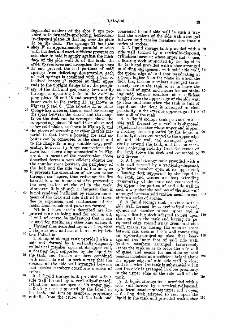
3,5111%,1 {16
se ‘ ental sections of the shoe F are pro vi ed with inwardly-projecting, horizontal ly-disposed lates16 that lap over the late 15 on the eck. The rings 11 hol -_the shoe F in approximatesliy parallel relation with the deck and exert sui?cient pressure on said shoe to hold it snugly a ainst the inner face of the side wall A o the tank In order to reinforce and strengthen the springs 11 and . revent the end portions of sald springs rom de?ectin downwardly, each of said springs is com ined with a pair of inclined braces 17 secured at their upper ends to the upright ?ange 12 at the periph cry of the deck and projecting downwardly through co-operating holes in the overlap» ping plates 15 and 16 and secured at their lower ends to the spring 11, as shown in Figures 5 and 6. The asbestos H or other sponge-like material that is used for closing the space between the shoe F and the ?ange 12 on the deck can be arranged above the co-operating plates 15 and 16 or above and below said plates, as shown in Figure 5, and the pieces of screening or other ?exible ma terial 14 that form a housing for said as bestos can be connected to the shoe F and to the ?ange 12 in any suitable way, pref erably, however, by hlnge connections that have been shown diagrammatically in Fig ure 5. A means of the construction above‘ described forms a very e?cient- closure for the annular space between the periphery of the deck and the side wall of the tank, as it prevents the circulation of air and vapor through said space, thus reducing the ?re hazard to a minimum and also preventing the evaporation of the oil in the tank. Moreover, it is of such a character that it is not rendered ine?icient by relative move ment of the deck and side wall of the tank, due to expansion and contraction of the metal from which said parts are formed. While I have herein described my im
proved tank as being used for storing oil, it will, of course, be understood that it can be used for storing any other kind of liquid. Having thus described my invention, what
I claim as new and desire to secure by Let ters Patent is:
1. A liquid storage tank provided with a side wall formed by a vertically-disposed, cylindrical member open at its upper end, a ?oating deck supported by the liquid in the tank, and tension members combined with said side wall in such a way that the sections of the side wall arranged between said tension members constitute a series of arches. '
2. A liquid storage tank provided with av side wall formed by a vertically-disposed, cylindrical member open at its upper end, a ?oating deck supported b the liquid in the tank, and tension mem ers projecting radially from the center of the tank and
a
connected to said side wall in such a way that the sections of the sidewall arranged between said tension members constitute a series of arches. '
3. A. liquid storage tank provided with a side well formed by a vertically-disposed, cylindrical memberwhose upper end is open, a ?oating deck supported ‘by the liquid in thetank and provided with a shoe arranged in sliding engagement with said side wall, the upper edge of said shoe terminating at a point higher than the plane in which the deck lies, tension members arranged trans versely across the tank so as to brace the side wall of same, and means for maintain~ ing said tension members at a suflicient height above the upper edge of the side wall to clear said shoe when the tank is full of liquid and the deck is arranged in close proximity to the extreme upper edge of the side wall of the tank. '
4. A liquid storage tank provided with a side wall formed by a vertically-disposed, cylindrical member whose upper end is open, a ?oating deck supported by the liquid in the tank, devices connected to the upper edge of said side Wall and arranged symmet rically around the tank, and tension mem bers projecting radially from the center of the tank above the deck and connected to said devices.
5. A liquid storage tank provided with a side wall formed by a vertically-disposed, cylindrical member open at its upper end, a ?oating deck supported by the liquid in the tank, and tension members extending transversely of the tank and connected to the upper edge portion of said side wall in ‘such a way that the sections of the side wall arranged between said tension members con stitute a series of arches.
6. A liquid storage tank provided with a side wall formed by a vertically-disposed, cylindrical member whose upper end is open, a ?oating deck adapted to rest upon the liquid in the tank and having its pe ripheral edge spaced awa from said side wall, means for closing the annular space between said deck and side wall comprising an upwardly~projecting shoe that bears against the inner face of said side wall, tension members arranged transversely across the tank so as to brace the side wall of same, and means for maintaining said tension members at a suiiicient height above the upper edge of said side wall to clear said shoe when the tank is substantially full and the deck is arran ed in close proximity to the upper edge 0' the side wall of the tank.
7. A liquid storage tank provided with a side "well formed by a vertically-disposed, cylindrical member whose upper end is open, a ?oatingdeck adapted to rest u on the liquid in the tank and provided wit a shoe
70
75
8.0
85
90
100
105
110'
115
120
125
130

10
20
25
30
35
40
‘so
' said shoe bears when the liqui
arranged in sliding enga ement with said side wall, and means projecting above the upper edge of said side wall a ainst wh1ch
in the tank is at such a level that the shoe projects above the upper edge of said side wall.
8. A liquid storage‘ tank provided with a side wall formed by a vertically-disposed, cylindrical member whose upper end is open, a ?oating deck adapted to rest upon the liquid in the vtank and having its peripheral edge spaced away from said side wall, means for closing the annular space between said deck and side wall comprising a shoe that bears against the inner face of said side wall, and upwardly-projecting guides at the upper edge of said side wall against which said shoe bears when the tank is full or sub stantially full of liquid. .
9. A liquid storage tank provided with a side wall formed by a vertically-disposed, cylindrical member whose upper end is open, a ?oating deck adapted to rest upon the liquid in the tank and provided with a shoe arranged in sliding engagement with .the inner face of said side wall, guides for said shoe that project upwardly above the top edge of said side wall, tension members ar ranged above the deck for bracing the tank against wind pressure and maintaining it in a truly circular shape, and devices on the upper edge portion of said side wall con nected to said tension members and con structed so as to not interfere with the up ward movement of said shoe when it is in engagement with said guides.
10. A liquid storage tank provided with a cylindrical side wall, a ?oating deck adapt- ‘ed to rest upon the liquid in the tank, a. closure for the space between said deck'and side wall comprising a shoe that slides upon said side wall, guides for said shoe that project upwardl above the top edge of the tank, substantia ly C-shaped devices con nected to the upper edge of said side wall and projecting inwardly from same, and tension members projecting radially from thecenter of the tank and connected to said C-shaped devices.
11. A liquid 'storage tank, comprising a side wall, a ?oating deck normally resting upon the liquid‘in the tank and having its
> peripheral edge spaced away from said side wall, a mass of sponge-like material ar ranged in the space between said deck and side wall, and means for preventing air or gases from circulating through said ma terial.
12. A liquid storage tank, comprising a side wall, a ?oating deck normally resting upon the liquid in the tank and having its peripheral edge spaced away from said side wall, a closure for the space between said deck and side wall‘ comprising a shoe ar ranged in sliding engagement-with said side
1,614,116
wall, and a mass of ?re-proof material of a sponge-like nature arran ed between said shoe and the periphery o the deck. ‘
13. A liquid storagetank, comprising a side wall, a‘ ?oating deck normally resting upon the liquid in the tank and having its peripheral edge spaced away from said side wall, a shoe‘ carried by said deck and ar ranged in sliding engagement with said side wall, a mass of asbestos or the like inter posed between said deck and shoe, means for preventing air or gases from circulat ing through said asbestos, and a-s?exible housing that pncases said asbestos.
14. A liquid storage tank, comprising a side wall formed by a vertically-disposed, cylindrical member whose upper end is open, a ?oating deck normally resting upon the liquid in the tank, a shoe surrounding said ‘ deck and arranged in sliding engagement with said side wall, and springs at the pe riphery of said deck that carry said shoe and hold it pressed against said side wall.
15. A liquid storage tank, comprising a side wall formed by) a-vertically-disposed, cylindrical member whose upper end is open,
70
75
so
85
90
a ?oating deck normally resting upon the . liquid in the tank, a shoe surrounding said deck and arranged in sliding engagement with said side wall, springs at the periphery of said deck that carry said shoe and hold
95
it pressed against said side wall, and means ' combined with said springs for maintaining said shoe in substantially parallel relation ship with said deck. . -
16. A liquid storage tank, comprising a side wall, a ?oating deck that normally rests upon the liquid in the tank, horizontally disposed leat' springs projecting outwardly from the peripheral edge of said deck, and a shoe surrounding said deck and combined with said springs in such a manner that said springs exert pressure on said shoe in a direction tending to hold it in engagement with said side wall.
17. A liquid. storage tank, comprising a side wall, a ?oating deck normally resting uponthe liquid in the tank, bowed leaf springs projecting outwardly from the pe riphery of the deck and connected inter mediate their ends to the deck, a shoe sur rounding said deck and arranged in slid ing engagement with the side wall, and guides on the inner side of said shoe in which the end portions of said springs are slidingly mounted.
18. A liquid storage tank, comprising a side wall, a ?oating deck normally resting upon the liquid in'the tank and provided at its peripheral edge with an upwardly projecting ?ange, a shoe surrounding said deck and arranged in sliding engagement with said side wall, bowed leaf springs con nected to the ?ange on the deck and to said shoe for pressing said shoe against said side
100
105
110
115
120
125
130

1,514,116
wall, and braces connected to said ?ange and to said springs for preventing the end portions of said springs from de?ecting downwardly.
19. A liquid storage tank, comprising a side wall, a ?oating deck normally resting
' upon the liquid in the tank and provided at
10
15
20
25
its periphery! with an upwardly-projecting ?ange, a shoe surrounding said ?ange and arranged in sliding engagement with said side wall, bowed leaf springs projecting out wardly from said ?ange that sustain said shoe and hold it pressed against said side wall, and means for closing the space be tween said shoe and ?ange.
20. A liquid storage tanlr, comprising a side wall, a ?oating deck normally resting upon the liquid in the tank and provided at its periphery with an upwardly-project ing ?ange, a shoe surrounding said ?ange and arranged in sliding engagement with said side wall, bowed leaf springs project; ing outwardly from said ?ange that sus tain said shoe and hold it pressed against said side wall, a mass of ?re~proof material
~ of a sponge-like nature arranged between
30
encases said material, and means for pre venting air or gases from circulating through said material.
21. A liquid storage tank, comprising a side wall, a ?oating deck normally resting upon the liquid in the tank and provided‘ at its periphery with an upwardly-proj ecting
35 ?ange, a shoe surrounding said ?ange and ar
5
ranged in sliding engagement with said side wall, bowed leaf springs projecting out wardly from said ?ange that sustain said shoe and hold it pressed against said side wall, and co-operating plates on said shoe and ?ange arranged in overlapping relation for preventing air or gases from circulating through said sponge-like material.
22. A liquid storage tank, comprising a side Wall, a ?oating deck normally resting upon the liquid in the tank and provided at its periphery with an upwardly—projecting ?ange,‘ bowed leaf springs connected inter mediate their ends to said ?ange and pro jecting outwardly therefrom, a shoe ar ranged in sliding engagement with said side wall and connected to said springs, horizon tally-disposed, overlapping plates on said shoe and ?ange arranged in sliding engage ment with each other, a mass of ?re-proof material of a sponge-like nature arranged in the space between said shoe and ?ange, a ?exible metallic housing that encases said sponge-like material, and means for pre venting the end portions of said springs from sagging or de?ecting downwardly. '
' said ?ange and shoe, a ?exible housing that ‘ 23. A llquid storage tank provided with a cylindrical side wall, substantially‘ C .shaped devices connected to the upper edge of said side wall in such a manner that the intermediate portions of same are spaced above the top edge of said side wall, and transversely-disposed tension members con— nected to said C-shaped devices. 7
JOHN H. WIGGINS.
40
45
50
55
60