Embed Size (px)
DESCRIPTION
Paten
Citation preview
US 20100150808A1
(12) Patent Application Publication (10) Pub. No.: US 2010/0150808 A1 (19) United States
Bhusarapu et al. (43) Pub. Date: Jun. 17, 2010
(54) PROCESSES FOR PRODUCING SILICON Related US. Application Data TETRAFLUORIDE FROM . . . .
FLUOROSILICATES IN A FLUIDIZED BED (60) Prov1s1onal applicatlon No. 61/138,158, ?led on Dec. REACTOR 17, 2008, provisional apphcation No. 61/138,160,
?led on Dec. 17, 2008.
(75) Inventors: Satish Bhusarapu, Houston, TX Publication Classi?cation (US); Puneet Gupta, Houston, TX (51) Int CL (Us) C01B 33/08 (2006.01)
(52) US. Cl. ...................................................... .. 423/341 Correspondence Address: Richard A. Schuth (MEMC) (57) ABSTRACT
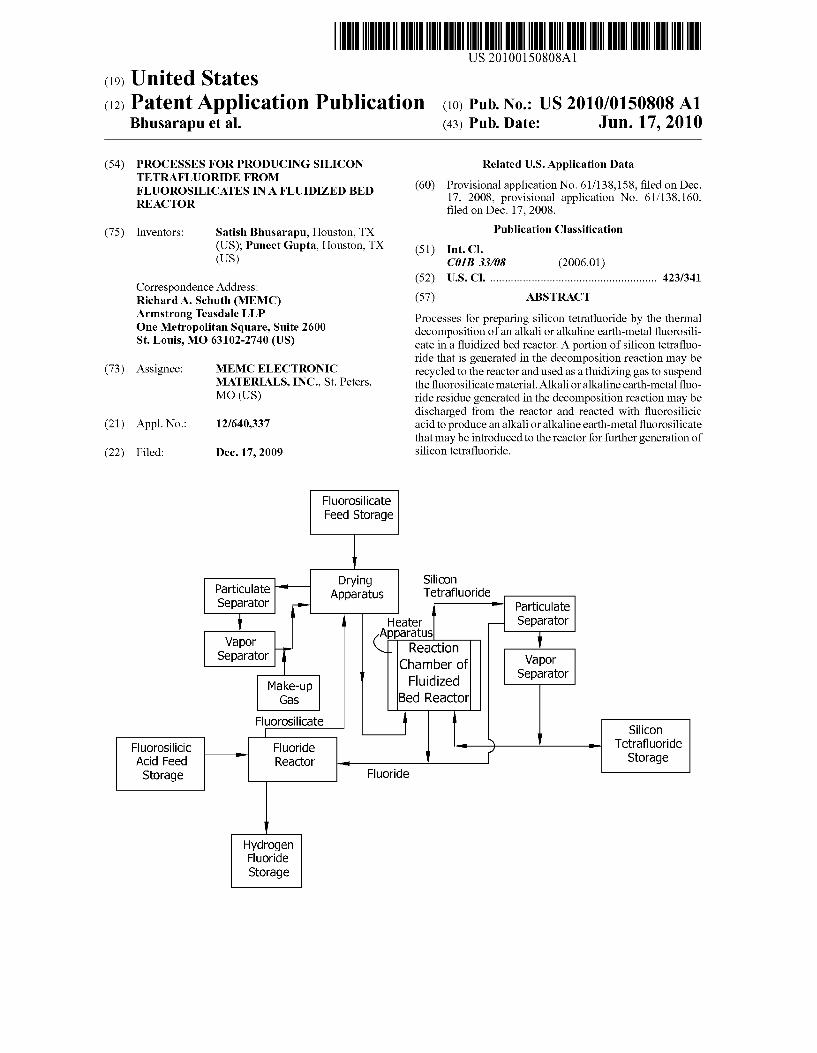
Armstrong Teasdale LLP _ Processes for preparing silicon tetra?uoride by the thermal one M‘ftmpohtan square’ sulte 2600 decomposition of an alkali or alkaline earth-metal ?uorosili st‘ LOUIS’ MO 63102'2740 (Us) cate in a ?uidized bed reactor. A portion of silicon tetra?uo
_ ride that is generated in the decomposition reaction may be (73) Assignee? MEMC ELECTRONIC recycled to the reactor and used as a ?uidiZing gas to suspend
MATERIALS, INC” Si- Peters: the ?uorosilicate material. Alkali or alkaline earth-metal ?uo MO (Us) ride residue generated in the decomposition reaction may be
discharged from the reactor and reacted With ?uorosilicic (21) Appl. No.: 12/640,337 acid to produce an alkali or alkaline earth-metal ?uorosilicate
that may be introduced to the reactor for further generation of (22) Filed; Dec, 17, 2009 silicon tetra?uoride.
Fluorosilicate Feed Storage
l . Drying Silicon
Partlculate ‘ Apparatus Tetrafluoride Separator ( '* Particulate
i ll AHeatetr Separator ppara us
sggggtor Q- Reaction i Chamber of Vapor
l Fluidized Separator Make-up Gas Bed Reactor
Fluorosilicate l i . . |— ‘ Slllcon
Fluorosilicic _ Fluoride 4 f ‘ Tetra?uor'de Acid Feed '' Reactor 4 i Storage
Storage Fluoride
l Hydrogen Fluoride Storage
Patent Application Publication Jun. 17, 2010 Sheet 1 0f 3 US 2010/0150808 A1
FIG. 1
18 V
V
V

US 2010/0150808 A1
PROCESSES FOR PRODUCING SILICON TETRAFLUORIDE FROM
FLUOROSILICATES IN A FLUIDIZED BED REACTOR
CROSS-REFERENCE TO RELATED APPLICATIONS
[0001] This application claims the bene?t of US. Provi sional Application No. 61/138,158, ?led Dec. 17, 2008 and US. Provisional Application No. 61/138,160, ?led Dec. 17, 2008, each of Which is incorporated herein by reference in its entirety.
BACKGROUND
[0002] The ?eld of the invention relates generally to prepa ration of silicon tetra?uoride and, more particularly, to the thermal decomposition of an alkali or alkaline earth-metal ?uorosilicate to silicon tetra?uoride and an alkali or alkaline earth-metal ?uoride in a ?uidized bed reactor. [0003] Silicon tetra?uoride is a versatile gas that may be used as a precursor in the production of silane. Silane is a valuable feedstock for production of polycrystalline silicon Which is used to produce semiconductors and solar cells. Silicon tetra?uoride may also be used for, for example, ion implantation, plasma deposition of ?uorinated silica and as a metal silicide etch. [0004] Silicon tetra?uoride has conventionally been pre pared by thermally decomposing an alkali or alkaline earth metal ?uorosilicate such as, for example, sodium ?uorosili cate. Fluorosilicates may be prepared by reacting ?uorosilicic acid With an alkali or alkaline earth-metal hydroxide, carbon ate or salt (e. g., NaCl). Fluorosilicic acid may be prepared as a by-product in the manufacture of phosphate fertilizers or by the reaction of sulfuric acid With barium hexa?uorosilicate, apatite or ?uorspar. [0005] One of the conventional methods to prepare silicon tetra?uoride gas involves the thermal decomposition of ?uo rosilicates by heating the ?uorosilicate in a kiln to produce silicon tetra?uoride gas and an alkali or alkaline earth-metal ?uoride as described in US. Pat. No. 5,242,670. Such pro cesses typically provide poor heat transfer to the ?uorosili cate material resulting in excessive energy use and often require the addition of silicon dioxide or aluminum trioxide to prevent the ?uoride residue from agglomerating into a solid block of residue as described in JP 10-231114. The use of silicon or aluminum oxides renders the residue commercially un?t for recycle because the residue becomes a mixture of unreacted silicon oxide or aluminum oxide and the ?uoride salt. The impurities in the residue mixture cause much loWer yields of recycled products. Accordingly, such residue mix tures are typically disposed of by land?ll application rather than by recycle. A need exists for processes and systems for producing silicon tetra?uoride from ?uorosilicates that e?i ciently transfer heat to the ?uorosilicate material and that produce by-products that may suitably be recycled.
SUMMARY
[0006] One aspect of the present invention is directed to a process for preparing silicon tetra?uoride by the thermal decomposition of an alkali or alkaline earth-metal ?uorosili cate in a ?uidiZed bed reactor. The ?uidiZed bed reactor includes a reaction chamber. Fluorosilicate and a ?uid media are introduced into the reaction chamber. The ?uorosilicate is
Jun. 17, 2010
suspended Within the ?uid media in the reaction chamber. The temperature of at least a portion of the reaction chamber is maintained above about 4000 C. to thermally decompose at least a portion or all of the ?uorosilicate and produce silicon tetra?uoride. The silicon tetra?uoride is then discharged from the reaction chamber. [0007] Another aspect of the present invention is directed to a process for preparing silicon tetra?uoride by the thermal decomposition of an alkali or alkaline earth-metal ?uorosili cate in a reaction chamber. Fluorosilicate is introduced into the reaction chamber and the temperature of at least a portion or all of the reaction chamber is maintained above about 4000 C. to thermally decompose a portion or all of the ?uorosilicate and produce silicon tetra?uoride. Silicon tetra?uoride is dis charged from the reaction chamber and a portion of the dis charged silicon tetra?uoride is introduced into the reaction chamber. [0008] Various re?nements exist of the features noted in relation to the above-mentioned aspects of the present inven tion. Further features may also be incorporated in the above mentioned aspects of the present invention as Well. These re?nements and additional features may exist individually or in any combination. For instance, various features discussed beloW in relation to any of the illustrated embodiments of the present invention may be incorporated into any of the above described aspects of the present invention, alone or in any combination.
BRIEF DESCRIPTION OF THE DRAWINGS
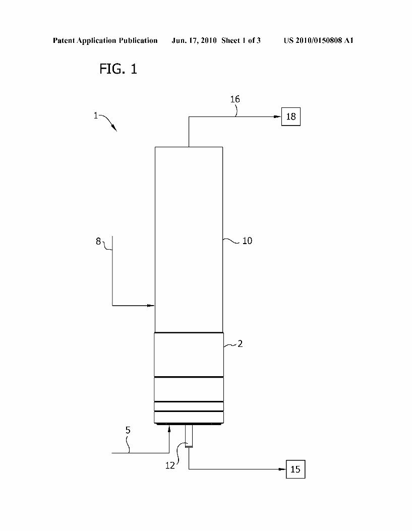
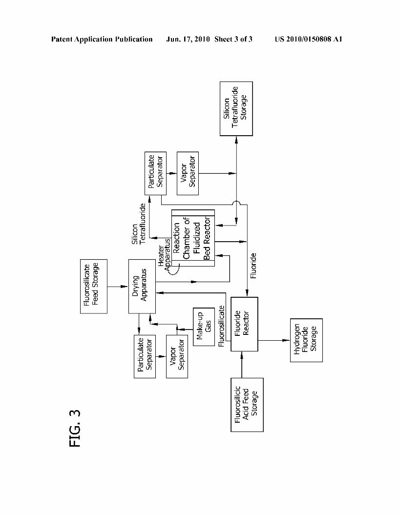
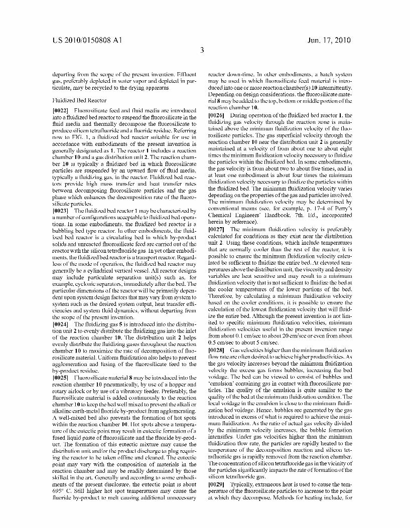
[0009] FIG. 1 is schematic of a ?uidiZed bed reactor includ ing the ?oWs entering and exiting the reactor; [0010] FIG. 2 is a ?oW diagram of a system for producing silicon tetra?uoride by the thermal decomposition of an alkali or alkaline earth-metal ?uorosilicate according to a ?rst embodiment of the present invention; and [0011] FIG. 3 is a ?oW diagram of a system for producing silicon tetra?uoride by the thermal decomposition of an alkali or alkaline earth-metal ?uorosilicate according to a second embodiment of the present invention.
DETAILED DESCRIPTION
[0012] Provisions of the present invention include pro cesses for preparing silicon tetra?uoride by the thermal decomposition of an alkali or alkaline earth-metal ?uorosili cate in a ?uidiZed bed reactor. A portion of silicon tetra?uo ride that is generated in the decomposition reaction may be recycled to the reactor and used to suspend the ?uorosilicate material. Alkali or alkaline earth-metal ?uoride residue gen erated in the decomposition reaction may be discharged from the reactor and reacted With ?uorosilicic acid to produce an alkali or alkaline earth-metal ?uorosilicate that may be intro duced to the reactor for further generation of silicon tetra?uo ride. [0013] Alkali and alkaline earth-metal ?uorosilicates ther mally decompose to produce silicon tetra?uoride and an alkali or alkaline earth-metal ?uoride as folloWs,
Wherein M is an alkali or alkaline earth-metal and x is 2 When M is an alkali and x is 1 When M is an alkaline earth-metal. Embodiments of processes of the present invention include introducing an alkali and/or alkaline earth-metal ?uorosili cate (often referred to herein as “?uorosilicate”) and ?uid media into the reaction chamber of a ?uidiZed bed reactor.
US 2010/0150808 A1
The ?uorosilicate becomes suspended Within the ?uid media in the reaction chamber. The temperature of at least a portion of the reaction chamber is maintained above the temperature at Which the ?uorosilicate decomposes, typically above a temperature of about 4000 C., to thermally decompose the ?uorosilicate and produce silicon tetra?uoride gas and alkali and/or alkaline earth-metal ?uoride. Silicon tetra?uoride is discharged from the reaction chamber and may be subjected to further processing steps including, for example, recycling of silicon tetra?uoride by introducing a portion or all of the discharged alkali and/or alkaline earth-metal ?uoride to the reaction chamber. The recycled silicon tetra?uoride acts as the ?uid media in Which the ?uorosilicate is suspended. Other processing steps may be performed in accordance With embodiments of the present invention, including, for example, drying of the ?uorosilicate feed and the removal of particulate and/or Water vapor from the silicon tetra?uoride decomposition product.
Fluorosilicate Feed
[0014] Preferably the ?uorosilicate feed is an alkali or alka line earth-metal ?uorosilicate. Suitable alkali or alkaline earth-metal ?uorosilicates include, for example, lithium ?uo rosilicate, sodium ?uorosilicate, potassium ?uorosilicate, magnesium ?uorosilicate, barium ?uorosilicate, calcium ?uorosilicate and mixtures thereof. In vieW of the Wide avail ability of sodium feedstocks such as caustic soda and potash that may be economically reacted With ?uorosilicic acid, a by-product produced in the manufacture of phosphate fertil iZers, to produce sodium ?uorosilicate, sodium ?uorosilicate is an especially preferred feedstock. [0015] The ?uorosilicate feedstock may contain any amount of impurities in accordance With embodiments of the present invention as the impurities typically stay in the solid phase and do not enter the product gas. In some embodiments, the ?uorosilicate feedstock includes less than about 2% impu rities by Weight on a dry basis, i.e., contains less than about 2% by Weight compounds other than alkali or alkaline earth metal ?uorosilicates and moisture; hoWever, ?uorosilicates containing any amount of impurities may be used Without departing from the scope of the present invention. In another embodiment, the ?uorosilicate feedstock includes less than about 1% impurities by Weight on a dry basis. If desired, the amount of impurities in ?uorosilicates may be removed by, for example, contacting the ?uorosilicate material With an absorbent that selectively absorbs the impurities. [0016] In some embodiments, the average nominal diam eter of the ?uorosilicate particles is less than about 500 um and, in other embodiments, from about 25 um to about 500 um and even from about 80 um to about 250 um. Commer cially sold ?uorosilicate typically contains ?uorosilicate par ticles in these particle siZe ranges and particle siZe reduction is not typically required. HoWever, if feedstocks With larger particle siZes are used, the particle siZe of the ?uorosilicate may be reduced by conventional methods such as, for example, by grinding or milling the ?uorosilicate. [0017] Fluorosilicate solids fed to the ?uidiZed bed reactor may contain less than about 3% by Weight moisture, less than about 2% by Weight moisture, less than about 1% by Weight moisture and even less than about 0.1% by Weight moisture. While ?uorosilicates containing higher moisture concentra tions may be used Without departing from the scope of the present invention, ?uorosilicates that contain higher amounts of moisture may agglomerate into clumps that are di?icult to
Jun. 17, 2010
heat and decompose and that are di?icult to suspend in the reactor. Silicon tetra?uoride product may further react With the moisture to produce undesirable hydrogen ?uoride and ?uorodisiloxanes Which can cause enhanced corrosion of the reaction chamber (Which may be made of, for example, heat resistant austenitic stainless steel). [0018] According to some embodiments of the present invention, moisture may be removed from the ?uorosilicate feed by introducing the ?uorosilicate material into a drying apparatus prior to introduction into the ?uidiZed bed reactor. The drying apparatus may be an indirect dryer such as, for example, a rotary dryer or a drum dryer or may be a direct dryer such as, for example, a ?uidiZed bed dryer, a belt dryer or a vacuum dryer. The drying apparatus and the ?uidiZed bed reactor may be combined into one unit (i.e., drying and ther mal decomposition occur in the same volume of the device); hoWever, it is preferred that any drying of ?uorosilicate mate rial occur before introduction of the ?uorosilicate material into the ?uidiZed bed reactor to improve process selectivity toWard silicon tetra?uoride and to reduce the amount of by products in the silicon tetra?uoride product gas. [0019] It should be noted that in embodiments Wherein the drying apparatus and the ?uidiZed bed reactor are combined into one unit (i.e., drying and thermal decomposition occur in the same volume of the device), the temperature and/ or ambi ent gases may be varied throughout the unit such that the temperature and/ or ambient gas in one or more regions of the apparatus favor drying the ?uorosilicate; Whereas, the tem perature and/or ambient gases in other region(s) favor the decomposition of the ?uorosilicate. If such multi-region designs are commercially impractical, the temperature and/ or ambient gas in the ?uidiZed bed reactor may be sWitched to a batch mode in Which ?uorosilicate feed is dried in a ?rst step at different temperature and ambient gas conditions.
[0020] Preferably, an ambient comprising an inert gas is circulated through the drying apparatus to remove evaporated Water vapor and help drive removal of moisture from the ?uorosilicate feedstock. Suitable inert gases include, for example, nitrogen, helium and argon. In some embodiments, an ambient comprising air depleted in moisture is circulated through the drying apparatus. Water vapor may be removed from air by, for example, utiliZing a chiller apparatus. The ambient and Water vapor may be driven or pulled though the drying apparatus by a recirculation fan or bloWer. Preferably, Water vapor and the ambient (collectively “ef?uent gas”) discharged from the drying apparatus are introduced into a particulate separator for removing particulates, namely ?uo rosilicate dust, entrained in the e?luent gas. Suitable particu late separators include, for example, bag ?lters, cyclonic separators and liquid scrubbers. Fluorosilicate dust may be recycled back to the drying apparatus or, more preferably, to the ?uidiZed bed reactor.
[0021] The e?luent gas may be introduced into a vapor separator, such as, for example, a mist eliminator or a liquid scrubber, to remove Water vapor. One example of a liquid scrubber is a venturi scrubber in Which Water vapor is atom iZed. In some embodiments, the particulate separator and the vapor separator are one unit (i.e., particulate and Water vapor are removed from the e?luent gas in the apparatus). In some embodiments, Water vapor in the e?luent gas is ?rst atomiZed to produce Water particles that impact the particulate. The particulate-incorporating Water particles may be removed in a cyclonic separator. The particulate and Water vapor may be removed from the ef?uent gas in any sequence Without
US 2010/0150808 A1
departing from the scope of the present invention. Ef?uent gas, preferably depleted in Water vapor and depleted in par ticulate, may be recycled to the drying apparatus.
Fluidized Bed Reactor
[0022] Fluorosilicate feed and ?uid media are introduced into a ?uidized bed reactor to suspend the ?uorosilicate in the ?uid media and thermally decompose the ?uorosilicate to produce silicon tetra?uoride and a ?uoride residue. Referring noW to FIG. 1, a ?uidized bed reactor suitable for use in accordance With embodiments of the present invention is generally designated as 1. The reactor 1 includes a reaction chamber 10 and a gas distribution unit 2. The reaction cham ber 10 is typically a ?uidized bed in Which ?uorosilicate particles are suspended by an upWard ?oW of ?uid media, typically a ?uidizing gas, in the reactor. Fluidized bed reac tors provide high mass transfer and heat transfer rates betWeen decomposing ?uorosilicate particles and the gas phase Which enhances the decomposition rate of the ?uoro silicate particles. [0023] The ?uidized bed reactor 1 may be characterized by a number of con?gurations acceptable to ?uidized bed opera tions. In some embodiments, the ?uidized bed reactor is a bubbling bed type reactor. In other embodiments, the ?uid ized bed reactor is a circulating bed in Which by-product solids and unreacted ?uorosilicate feed are carried out of the reactor With the silicon tetra?uoride gas. In yet other embodi ments, the ?uidized bed reactor is a transport reactor. Regard less of the mode of operation, the ?uidized bed reactor may generally be a cylindrical vertical vessel. All reactor designs may include particulate separation unit(s) such as, for example, cyclonic separators, immediately after the bed. The particular dimensions of the reactor Will be primarily depen dent upon system design factors that may vary from system to system such as the desired system output, heat transfer e?i ciencies and system ?uid dynamics, Without departing from the scope of the present invention. [0024] The ?uidizing gas 5 is introduced into the distribu tion unit 2 to evenly distribute the ?uidizing gas into the inlet of the reaction chamber 10. The distribution unit 2 helps evenly distribute the ?uidizing gases throughout the reaction chamber 10 to maximize the rate of decomposition of ?uo rosilicate material. Uniform ?uidization also helps to prevent agglomeration and fusing of the ?uorosilicate feed to the by-product residue. [0025] Fluorosilicate material 8 may be introduced into the reaction chamber 10 pneumatically, by use of a hopper and rotary airlock or by use of a vibratory feeder. Preferably, the ?uorosilicate material is added continuously to the reaction chamber 10 to keep the bed Well mixed to prevent the alkali or alkaline earth-metal ?uoride by-product from agglomerating. A Well-mixed bed also prevents the formation of hot spots Within the reaction chamber 10. Hot spots above a tempera ture of the eutectic point may result in eutectic formation of a fused liquid paste of ?uorosilicate and the ?uoride by-prod uct. The formation of this eutectic mixture may cause the distribution unit and/ or the product discharge to plug requir ing the reactor to be taken o?line and cleaned. The eutectic point may vary With the composition of materials in the reaction chamber and may be readily determined by those skilled in the art. Generally and according to some embodi ments of the present disclosure, the eutectic point is about 695° C. Still higher hot spot temperatures may cause the ?uoride by-product to melt causing additional unnecessary
Jun. 17, 2010
reactor doWn-time. In other embodiments, a batch system may be used in Which ?uorosilicate feed material is intro duced into one or more reaction chamber(s) 10 intermittently. Depending on design considerations, the ?uorosilicate mate rial 8 may be added to the top, bottom or middle portion of the reaction chamber 10.
[0026] During operation of the ?uidized bed reactor 1, the ?uidizing gas velocity through the reaction zone is main tained above the minimum ?uidization velocity of the ?uo rosilicate particles. The gas super?cial velocity through the reaction chamber 10 near the distribution unit 2 is generally maintained at a velocity of from about one to about eight times the minimum ?uidization velocity necessary to ?uidize the particles Within the ?uidized bed. In some embodiments, the gas velocity is from about tWo to about ?ve times, and in at least one embodiment is about four times the minimum ?uidization velocity necessary to ?uidize the particles Within the ?uidized bed. The minimum ?uidization velocity varies depending on the properties of the gas and particles involved. The minimum ?uidization velocity may be determined by conventional means (see, for example, p. 17-4 of Perry’s Chemical Engineers’ Handbook, 7th. Ed., incorporated herein by reference). [0027] The minimum ?uidization velocity is preferably calculated for conditions as they exist near the distribution unit 2. Using these conditions, Which include temperatures that are normally cooler than the rest of the reactor, it is possible to ensure the minimum ?uidization velocity calcu lated be suf?cient to ?uidize the entire bed. At elevated tem peratures above the distribution unit, the viscosity and density variables are heat sensitive and may result in a minimum ?uidization velocity that is not su?icient to ?uidize the bed at the cooler temperatures of the loWer portions of the bed. Therefore, by calculating a minimum ?uidization velocity based on the cooler conditions, it is possible to ensure the calculation of the loWest ?uidization velocity that Will ?uid ize the entire bed. Although the present invention is not lim ited to speci?c minimum ?uidization velocities, minimum ?uidization velocities useful in the present invention range from about 0.1 cm/ sec to about 20 cm/ sec or even from about 0.5 cm/sec to about 5 cm/sec.
[0028] Gas velocities higher than the minimum ?uidization ?oW rate are often desired to achieve higher productivities. As the gas velocity increases beyond the minimum ?uidization velocity the excess gas forms bubbles, increasing the bed voidage. The bed can be vieWed to consist of bubbles and ‘emulsion’ containing gas in contact With ?uorosilicate par ticles. The quality of the emulsion is quite similar to the quality of the bed at the minimum ?uidization condition. The local voidage in the emulsion is close to the minimum ?uidi zation bed voidage. Hence, bubbles are generated by the gas introduced in excess of What is required to achieve the mini mum ?uidization. As the ratio of actual gas velocity divided by the minimum velocity increases, the bubble formation intensi?es. Under gas velocities higher than the minimum ?uidization ?oW rate, the particles are rapidly heated to the temperature of the decomposition reaction and silicon tet ra?uoride gas is rapidly removed from the reaction chamber. The concentration of silicon tetra?uoride gas in the vicinity of the particles signi?cantly impacts the rate of formation of the silicon tetra?uoride gas.
[0029] Typically, extraneous heat is used to cause the tem perature of the ?uorosilicate particles to increase to the point at Which they decompose. Methods for heating include, for
US 2010/0150808 A1
example, capacitive heating, induction coils (RF) and electri cal resistance elements. In some embodiments, the ?uidiZing gas is heated prior to introduction into the reaction chamber 10. Upon introduction into the reaction chamber 10, the ?u idiZing gas transfers heat to the particles causing them to thermally decompose. In some embodiments, both extrane ous addition of heat and pre-heating of the ?uidiZing gas are employed. [0030] The temperature in the reaction chamber 10 is pref erably maintained above the temperature at Which the ?uo rosilicate material decomposes to produce silicon tetra?uo ride and an alkali or alkaline earth-metal ?uoride. The temperature of the reaction chamber 10 may be maintained above about 400° C., typically from about 400° C. to about 800° C., from about 400° C. to about 750° C. and even from about 500° C. to about 695° C. Preferably, the temperature in the reaction chamber 10 is maintained beloW the temperature at Which the ?uoro silicate and ?uoride residue form a eutectic mixture (often about 695° C.) and beloW the melting tempera ture of the alkali or alkaline earth-metal ?uoride. [0031] Because the decomposition reaction is a reversible reaction and the degree of thermal decomposition is depen dent, in part, upon the pressure in the reactor, the pressure (absolute) in the reactor (as measured above the reactor at the point at Which exhaust gas 1 6 exits the reaction chamber) may preferably be maintained beloW about 1 bar. In another embodiment, the pressure is maintained from about 0.001 bar to about 1 bar. In other embodiments, the pressure is main tained from about 0.001 bar to about 0.9 bar, from about 0.001 bar to about 0.5 bar, from about 0.001 bar to about 0.1 bar or even from about 0.001 bar to about 0.01 bar. [0032] The alkali or alkaline earth-metal ?uorosilicate material decomposes to produce silicon tetra?uoride gas and alkali or alkaline earth-metal ?uoride residue. The residue is typically a poWder and may be WithdraWn from the reaction chamber through a gravity drop (not shoWn) at the base of the reaction chamber, through a by-product WithdraWal tube 12 and to ?uoride residue storage 15. In another embodiment, the residue exits the reaction chamber 10 With the silicon tetra?uoride exhaust gas 16 and is separated from the gas by a particulate separator such as, for example, a cyclonic sepa rator. Preferably the residue is removed continuously from the reaction chamber 10; hoWever, the residue may be removed intermittently (i.e., by batch-Wise methods) Without departing from the scope of the present invention. Preferably, the average period of time betWeen introduction of a ?uoro silicate particle into the reaction chamber 10 and discharge of the corresponding ?uoride residue produced as a by-product of the thermal decomposition of the ?uorosilicate particle is from about 5 minutes to about 50 minutes or from about 10 minutes to about 30 minutes. [0033] It should be noted that any reactor capable of carry ing out the above described processes may be used Without departing from the scope of the present invention. Such reac tors are generally described as ?uidiZed bed reactors. Further more, the process of the present invention may carry out the reaction in a single ?uidiZed bed reactor or may incorporate one or more ?uidiZed bed reactors con?gured in series and/or in parallel.
Exhaust Gas Treatment
[0034] The ?uidiZing gas and the silicon tetra?uoride gas produced as a decomposition product (collectively “exhaust gas”) 16 exit the reactor chamber 10 and may be introduced
Jun. 17, 2010
into further processing units 18. The exhaust gas may be driven or pulled though the ?uidiZed bed reactor by a recir culation fan or bloWer. The exhaust gas may be introduced into a particulate separator for removing alkali or alkaline earth-metal ?uoride or ?uorosilicate dust entrained in the exhaust gas. Suitable particulate separators include, for example, ceramic and metallic dust ?lters and cyclonic sepa rators. Fluoride removed from the exhaust gas may be dis posed of or recycled as described more fully beloW. In some embodiments, particulate removed from the exhaust gas is recycled back to the ?uidiZed bed reactor 1. [0035] Exhaust gas may be introduced into a vapor separa tor, such as, for example, a condenser trap that cools the exhaust gas and condenses and removes any Water vapor and any hydrogen ?uoride present in the gas. The particulate and Water vapor may be removed in any sequence Without depart ing from the scope of the present invention. Exhaust gas, preferably depleted in Water vapor and depleted in particu late, may be WithdraWn from the system as a product gas. The product gas may be stored as a solid at liquid nitrogen tem peratures or as a pressuriZed gas. A portion of the exhaust gas may be recycled to the ?uidiZed bed reactor as the ?uidiZing gas. [0036] Preferably the ?uidiZing gas used in the ?uidiZed bed reactor is a portion of the silicon tetra?uoride gas dis charged from the reactor. HoWever, other ?uidiZing gases may be used such as inert gases including, for example, nitrogen, helium and argon, Without departing from the scope of the present invention. If a ?uidiZing gas other than silicon tetra?uoride is used in the reaction chamber, silicon tetra?uo ride in the exhaust gas is preferably separated from the ?uid iZing gas for product recovery. Separation techniques include, for example, adsorption, membrane separation and distilla tion.
Alkali and Alkaline Earth-Metal Fluoride Treatment
[0037] The alkali or alkaline earth-metal ?uoride residue WithdraWn from the reactor may be collected as a product or, more preferably, further processed and recycled to the reac tion chamber 10. The ?uoride residue may be reacted With ?uorosilicic acid to produce an alkali or alkaline earth-metal ?uorosilicate as folloWs,
Wherein M is an alkali or alkaline earth-metal and x is 2 When M is an alkali and x is 1 When M is an alkaline earth-metal. Alkali or alkaline earth-metal ?uoride may be added directly to liquid ?uorosilicic acid to produce a supernatant liquid containing hydrogen ?uoride and unreacted alkali or alkaline earth-metal ?uoride and ?uorosilicic acid and precipitated ?uorosilicate. The precipitated ?uorosilicate may be sepa rated from the supernatant liquid and introduced into the reaction chamber 10 of the ?uidiZed bed reactor 1. Preferably the ?uorosilicate is puri?ed and dried prior to introduction into the ?uidiZed bed reactor 1. The ?uorosilicate material may be introduced into the drying apparatus used to dry ?uorosilicate feed material as shoWn in FIG. 3. The hydrogen ?uoride supernatant may be puri?ed and collected as a prod uct or utiliZed to produce additional silicon tetra?uoride. The hydrogen ?uoride may be reacted With silicon oxide to pro duce additional silicon tetra?uoride as folloWs,
System for Preparing Silicon Tetra?uoride [0038] The processes of the present invention may be car ried out in a system for producing silicon tetra?uoride such

US 2010/0150808 A1
as, for example, the system shown in FIG. 2 or the system shown in FIG. 3. The system includes alkali or alkaline earth metal feed storage (“?uorosilicate feed storage”). The ?uo rosilicate feed is conveyed by a conveying apparatus to a drying apparatus for removing moisture from the ?uorosili cate feed. An e?luent gas from the drying apparatus contain ing Water vapor removed from the ?uorosilicate feed is intro duced to an e?luent gas treatment system that includes a particulate separator and a vapor separator. The particulate separator separates ?uorosilicate dust from an e?luent gas recirculated throughout the drying apparatus. A vapor sepa rator removes Water vapor generated in the drying apparatus. The particulate and Water vapor may be removed from the e?luent gas in any sequence Without departing from the scope of the present invention. A make-up gas comprising an inert gas such as, for example, nitrogen, helium and argon, or optionally moisture-depleted air may be fed to the ef?uent gas treatment system. A conveying apparatus conveys ?uorosili cate feed from the drying apparatus to a ?uidized bed reactor that includes a reaction chamber for thermal decomposition of ?uorosilicate into silicon tetra?uoride gas and an alkali or alkaline earth-metal ?uoride. The system includes a heater apparatus in thermal communication With the reaction cham ber.
[0039] The exhaust gas produced in the ?uidized bed reac tor is introduced into an exhaust gas treatment system that includes a particulate separator in ?uid communication With the ?uidiZed bed reactor for removing alkali or alkaline earth metal ?uoride and/or ?uorosilicate dust from the gases dis charged from the ?uidiZed bed reactor. The exhaust gas treat ment system may also include a vapor separator for condensing and removing Water vapor from the gases dis charged from the ?uidiZed bed reactor. The particulate and Water vapor may be removed from the ef?uent gas in any sequence Without departing from the scope of the present invention. The system may include a silicon tetra?uoride product storage system. A conveying apparatus transfers a portion of the silicon tetra?uoride gas discharged from the ?uidiZed bed reactor back to the ?uidiZed bed reactor as a ?uidiZing gas. [0040] The system may include a ?uoride treatment system comprising a ?uoride reactor. A conveying apparatus conveys alkali or alkaline earth-metal ?uoride discharged from the particulate separator (or alternatively or in addition dis charged from the ?uidiZed bed reactor) to the ?uoride reactor. Fluorosilicic acid is reacted With an alkali or alkaline earth metal ?uoride in the ?uoride reactor to produce alkali or alkaline earth-metal ?uorosilicate. Fluorosilicate material discharged from the ?uoride reactor may be conveyed by a conveying apparatus to the ?uidiZed bed reactor. The ?uoro silicate material may be puri?ed (not shoWn) and/ or dried in a drying apparatus as shoWn in FIG. 2 prior to introduction into the ?uidiZed bed reactor. The drying apparatus may be the same drying apparatus used to dry ?uorosilicate feed material as shoWn in FIG. 3.
[0041] Suitable conveying apparatus are conventional and Well knoWn in the art. Suitable conveying apparatus for the transfer of gases include, for example, a recirculation fan or bloWer and suitable conveying apparatus for transfer of solids include, for example, drag, screW, belt and pneumatic con veyors. [0042] Preferably, all equipment utiliZed in the system for producing silicon tetra?uoride is resistant to corrosion in an environment that includes exposure to acidic compounds and,
Jun. 17, 2010
more particularly, exposure to ?uorine-containing com pounds including, for example, silicon tetra?uoride, alkali or alkaline earth-metal ?uoride, silicon tetra?uoride and hydro gen ?uoride. Suitable materials of construction are conven tional and Well-knoWn in the ?eld of the invention and include, for example, austenitic stainless steel, MONEL alloys, INCONEL alloys, HASTELLOY alloys and nickel. [0043] When introducing elements of the present invention or the preferred embodiments(s) thereof, the articles “a”, “an”, “the” and “said” are intended to mean that there are one or more of the elements. The terms “comprising”, “includ ing” and “having” are intended to be inclusive and mean that there may be additional elements other than the listed ele ments.
[0044] As various changes could be made in the above apparatus and methods Without departing from the scope of the invention, it is intended that all matter contained in the above description and shoWn in the accompanying ?gures shall be interpreted as illustrative and not in a limiting sense.
What is claimed is: 1. A process for preparing silicon tetra?uoride by the ther
mal decomposition of an alkali or alkaline earth-metal ?uo rosilicate in a ?uidiZed bed reactor, the ?uidiZed bed reactor comprising a reaction chamber, the process comprising:
introducing ?uorosilicate and a ?uid media into the reac tion chamber;
suspending the ?uorosilicate Within the ?uid media in the reaction chamber;
maintaining the temperature of the reaction chamber above about 400° C. to thermally decompose the ?uorosilicate and produce silicon tetra?uoride; and
discharging silicon tetra?uoride from the reaction cham her.
2. A process as set forth in claim 1 Wherein the ?uid media comprises silicon tetra?uoride gas.
3. A process as set forth in claim 1 Wherein a portion of the discharged silicon tetra?uoride is introduced into the reaction chamber to suspend ?uorosilicate in the reaction chamber.
4. A process as set forth in claim 1 Wherein the ?uorosili cate decomposes to produce an alkali or alkaline earth-metal ?uoride.
5. A process as set forth in claim 4 Wherein the reaction chamber is maintained beloW the melting temperature of the alkali or alkaline earth-metal ?uoride.
6. A process as set forth in claim 4 Wherein the reaction chamber is maintained beloW a temperature at Which the alkali or alkaline earth-metal ?uoride and the ?uorosilicate form a eutectic mixture.
7. A process as set forth in claim 1 Wherein the ?uorosili cate is selected from the group consisting of lithium ?uoro silicate, sodium ?uorosilicate, potassium ?uorosilicate, mag nesium ?uorosilicate, barium ?uorosilicate, calcium ?uorosilicate and mixtures thereof.
8. A process as set forth in claim 1 Wherein the ?uorosili cate is sodium ?uorosilicate.
9. A process as set forth in claim 1 Wherein the reaction chamber is maintained at a temperature from about 400° C. to about 800° C.
10. A process as set forth in claim 1 Wherein the reaction chamber is maintained at a temperature from about 400° C. to about 750° C.
11. A process as set forth in claim 1 Wherein the reaction chamber is maintained at a temperature from about 500° C. to about 695° C.
US 2010/0150808 A1
12. A process as set forth in claim 1 wherein the reaction chamber comprises a sidewall and Wherein the temperature of the reaction chamber is maintained from about 400° C. to about 800° C. by applying heat to the reaction chamber side Wall.
13. A process as set forth in claim 12 Wherein heat is applied to the sideWall by a resistance heater.
14. A process as set forth in claim 12 Wherein the heat is applied to the sideWall by contacting the sideWall With a combusted gas.
15. A process as set forth in claim 12 Wherein the heat is applied to the sideWall by inductively heating the sideWall With an induction coil.
16. A process as set forth in claim 1 Wherein the tempera ture of the reaction chamber is maintained from about 400° C. to about 800° C. by heating a portion of the discharged silicon tetra?uoride and introducing the heated silicon tetra?uoride to the reaction chamber.
17. A process as set forth in claim 1 Wherein the reaction chamber comprises a sideWall and Wherein the temperature of the reaction chamber is maintained from about 400° C. to about 800° C. by (l) applying heat to the reaction chamber sideWall and (2) heating a portion of the discharged silicon tetra?uoride and introducing the heated silicon tetra?uoride to the reaction chamber.
18. A process as set forth in claim 1 Wherein the ?uorosili cate is a poWder comprising poWder particles.
19. A process as set forth in claim 18 Wherein the particles have an average nominal diameter of from about 25 pm to about 500 um.
20. A process as set forth in claim 18 Wherein the ?uoro silicate poWder particles decompose to produce silicon tet ra?uoride gas and a solid residue of alkali or alkaline earth metal ?uoride.
21. A process as set forth in claim 20 Wherein the ?uoride residue is discharged from the reaction chamber.
22. A process as set forth in claim 21 Wherein the average period of time betWeen introduction of a ?uorosilicate poW der particle into the reaction chamber and discharge of the corresponding ?uoride residue is from about 5 minutes to about 50 minutes.
23. A process as set forth in claim 21 Wherein the average period of time betWeen introduction of a ?uorosilicate poW der particle into the reaction chamber and discharge of the corresponding ?uoride residue is from about 10 minutes to about 30 minutes.
24. A process as set forth in claim 20 Wherein the ?uoride residue is discharged from the reaction chamber With the silicon tetra?uoride discharged from the reaction chamber and Wherein the ?uoride residue is separated from the dis charged silicon tetra?uoride in a particulate separator.
25. A process as set forth in claim 1 Wherein the reaction chamber is maintained at an absolute pressure of less than about 1 bar.
26. A process as set forth in claim 1 Wherein the reaction chamber is maintained at an absolute pressure of from about 0.001 bar to about 1 bar.
27. A process as set forth in claim 1 Wherein the reaction chamber is maintained at an absolute pressure of from about 0.001 bar to about 0.1 bar.
28. A process as set forth in claim 1 Wherein the reaction chamber is maintained at an absolute pressure of from about 0.001 bar to about 0.01 bar.
Jun. 17, 2010
29. A process as set forth in claim 1 Wherein the ?uorosili cate is dried prior to introduction into the reaction chamber.
30. A process as set forth in claim 1 Wherein the ?uorosili cate decomposes to produce a solid residue of an alkali or alkaline earth-metal ?uoride and Wherein the process further comprises:
discharging ?uoride residue from the reaction chamber; reacting the ?uoride residue With ?uorosilicic acid to pro
duce an alkali or alkaline earth-metal ?uorosilicate; and introducing the alkali or alkaline earth-metal ?uorosilicate
into the reaction chamber. 31. A process for preparing silicon tetra?uoride by the
thermal decomposition of an alkali or alkaline earth-metal ?uorosilicate in a reaction chamber, the process comprising:
introducing ?uorosilicate into the reaction chamber; maintaining the temperature of the reaction chamber above
about 400° C. to thermally decompose the ?uorosilicate and produce silicon tetra?uoride;
discharging silicon tetra?uoride from the reaction cham ber; and
introducing a portion of the discharged silicon tetra?uoride into the reaction chamber.
32. A process as set forth in claim 31 Wherein the dis charged silicon tetra?uoride is introduced into the reaction chamber as a ?uidiZing gas to suspend ?uorosilicate in the reaction chamber.
33. A process as set forth in claim 31 Wherein the ?uoro silicate decomposes to produce an alkali or alkaline earth metal ?uoride.
34. A process as set forth in claim 33 Wherein the reaction chamber is maintained beloW the melting temperature of the alkali or alkaline earth-metal ?uoride.
35. A process as set forth in claim 33 Wherein the reaction chamber is maintained beloW a temperature at Which the alkali or alkaline earth-metal ?uoride and ?uorosilicate form a eutectic mixture.
36. A process as set forth in claim 31 Wherein the ?uoro silicate is selected from the group consisting of lithium ?uo rosilicate, sodium ?uorosilicate, potassium ?uorosilicate, magnesium ?uorosilicate, barium ?uorosilicate, calcium ?uorosilicate and mixtures thereof.
37. A process as set forth in claim 31 Wherein the ?uoro silicate is sodium ?uorosilicate.
38. A process as set forth in claim 31 Wherein the reaction chamber is maintained at a temperature from about 400° C. to about 800° C.
39. A process as set forth in claim 31 Wherein the reaction chamber is maintained at a temperature from about 400° C. to about 750° C.
40. A process as set forth in claim 31 Wherein the reaction chamber is maintained at a temperature from about 500° C. to about 695° C.
41. A process as set forth in claim 31 Wherein the reaction chamber comprises a sideWall and Wherein the temperature of the reaction chamber is maintained from about 400° C. to about 800° C. by applying heat to the reaction chamber side Wall.
42. A process as set forth in claim 41 Wherein heat is applied to the sideWall by a resistance heater.
43. A process as set forth in claim 41 Wherein the heat is applied to the sideWall by contacting the sideWall With a combusted gas.
US 2010/0150808 A1
44. A process as set forth in claim 41 wherein the heat is applied to the sidewall by inductively heating the sideWall With an induction coil.
45. A process as set forth in claim 31 Wherein the tempera ture of the reaction chamber is maintained from about 4000 C. to about 8000 C. by heating a portion of the discharged silicon tetra?uoride and introducing the heated silicon tetra?uoride to the reaction chamber.
46. A process as set forth in claim 31 Wherein the reaction chamber comprises a sideWall and Wherein the temperature of the reaction chamber is maintained from about 4000 C. to about 8000 C. by (l) applying heat to the reaction chamber sideWall and (2) heating a portion of the discharged silicon tetra?uoride and introducing the heated silicon tetra?uoride to the reaction chamber.
47. A process as set forth in claim 31 Wherein the ?uoro silicate is a poWder comprising poWder particles.
48. A process as set forth in claim 47 Wherein the particles have an average nominal diameter of from about 25 pm to about 500 um.
49. A process as set forth in claim 47 Wherein the ?uoro silicate poWder particles decompose to produce silicon tet ra?uoride gas and a solid residue of alkali or alkaline earth metal ?uoride.
50. A process as set forth in claim 49 Wherein the ?uoride residue is discharged from the reaction chamber.
51. A process as set forth in claim 50 Wherein the average period of time betWeen introduction of a ?uorosilicate poW der particle into the reaction chamber and discharge of the corresponding ?uoride residue is from about 5 minutes to about 50 minutes.
52. A process as set forth in claim 50 Wherein the average period of time betWeen introduction of a ?uorosilicate poW
Jun. 17, 2010
der particle into the reaction chamber and discharge of the corresponding ?uoride residue is from about 10 minutes to about 30 minutes.
53. A process as set forth in claim 49 Wherein the ?uoride residue is discharged from the reaction chamber With the silicon tetra?uoride discharged from the reaction chamber and Wherein the ?uoride residue is separated from the silicon tetra?uoride in a particulate separator.
54. A process as set forth in claim 31 Wherein the reaction chamber is maintained at an absolute pressure of less than about 1 bar.
55. A process as set forth in claim 31 Wherein the reaction chamber is maintained at an absolute pressure of from about 0.001 bar to about 1 bar.
56. A process as set forth in claim 31 Wherein the reaction chamber is maintained at an absolute pressure of from about 0.001 bar to about 0.1 bar.
57. A process as set forth in claim 31 Wherein the reaction chamber is maintained at an absolute pressure of from about 0.001 bar to about 0.01 bar.
58. A process as set forth in claim 31 Wherein the ?uoro silicate is dried prior to introduction into the reaction cham ber.
59. A process as set forth in claim 31 Wherein the ?uoro silicate decomposes to produce a solid residue of an alkali or alkaline earth-metal ?uoride and Wherein the process further comprises:
discharging ?uoride residue from the reaction chamber; reacting the ?uoride residue With ?uorosilicic acid to pro
duce an alkali or alkaline earth-metal ?uorosilicate; and introducing the alkali or alkaline earth-metal ?uorosilicate
to the reaction chamber.
* * * * *