Embed Size (px)
DESCRIPTION
patent
Citation preview
United States Patent [19] Nishida et al.
[54] METHOD OF SEPARATING CARBON MONOXIDE AND CARBON MONOXIDE ADSORBENT USED IN THIS METHOD
[75] Inventors: Taisuke Nishida, Tokyo; Kazuo Tajima, Hiratsuka; Yo Osada; Osamu Shigyo, both of Yokohama; Hiroaki Taniguchi, Kuki, all of Japan
Nippon Kokan Kabushiki Kaisha, Tokyo, Japan
[21] Appl. No.: 948,394 [22] Filed: Dec. 31, 1986
[73] Assignee:
Related U.S. Application Data
[63] Continuation of Ser. No. 751,038, Jul. 1, 1985, aban doned.
[30] Foreign Application Priority Data Jul. 4, 1984 [JP] Japan 59-138771 Jul. 4, 1984 [JP] Japan 59-138772 Apr. 8, 1985 [JP] Japan . . . . . . . . . .. 60-72696
Apr. 8, 1985 [JP] Japan ................................ .. 60-72697
[51] Int. Cl.‘ ............................................ .. B01D 53/04 [52] U.S. Cl. ................................ .. 55/68; 55/75 [58] Field of Search ........................... .. 55/68, 75, 389;
423/246, 247, 415 A; 502/75, 77-79, 406, 407
[56] References Cited U.S. PATENT DOCUMENTS
3,013,982 12/1961 Breck et a1. .................... .. 502/75 X 3,185,540 5/1965 Breck et a1. .. 423/247 3,331,190 7/1967 Glew et a1. 55/75 X 3,407,039 10/1968 Bryant ............................ .. 502/78 X
4,743,276 May 10, 1988
[11] Patent Number:
[45] Date of Patent:
3,476,508 11/1969 Kearby et al. ................ .. 423/247 X 3,497,462 2/1970 Kruerke . . . . . . . . . . . . . . . . . . .. 502/75
3,755,540 8/1973 Rasback 502/75 X 3,789,106 l/l974 Hay ............. .. 55/68 X 4,019,879 4/1977 Rabo et al. ..... .. 55/68
4,019,880 4/1977 Rabo et a1. 4,180,693 12/1979 Marcilly .......... ..
4,297,328 10/1981 Ritscher et a1. .. 4,358,297 1l/1982 Eberly, Jr. . . . . . . . . . . . . .. 55/75 X
4,470,829 9/ 1984 Hirai et a1. . . . . . . . . . . . . .. 55/68
4,539,020 9/1985 Sakuraya et a1. ................. .. 55/68 X
FOREIGN PATENT DOCUMENTS
18700 11/ 1980 European Pat. Off. ...... .. 423/415 A 1512263 12/ 1967 France . 2335258 7/ 1977 France .
7255 l/1982 Japan ............................ .. 423/415 A
58-156517 9/1983 Japan . 59-22625 2/1984 Japan . 59-26121 2/1984 Japan . 662460 12/ 1951 United Kingdom .............. .. 423/247
Primary Examiner-Robert Spitzer Attorney, Agent, or Firm—Frishauf, Holtz, Goodman & Woodward
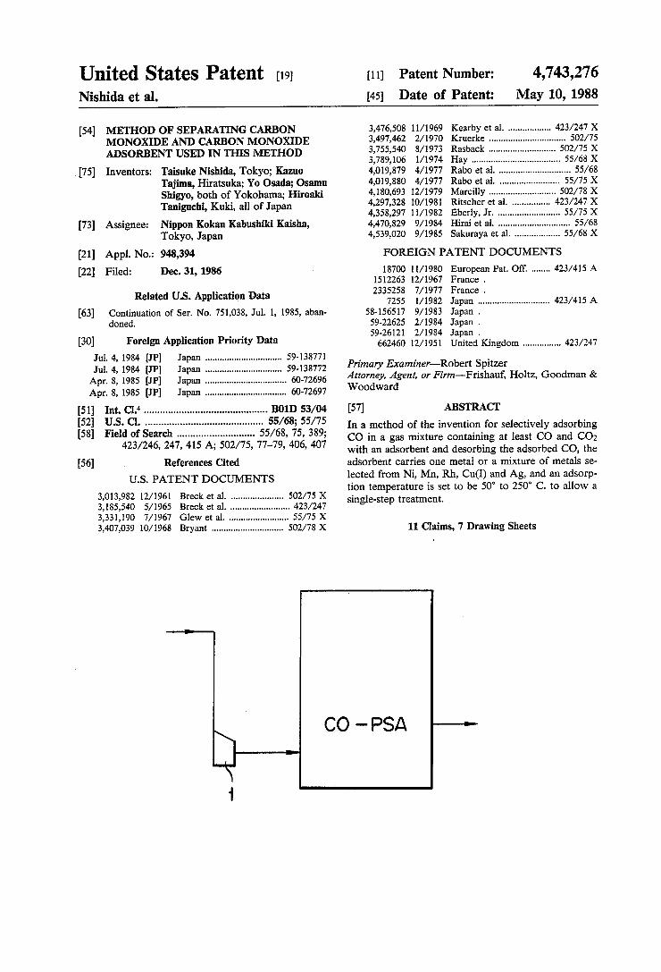
[57] ABSTRACT In a method of the invention for selectively adsorbing CO in a gas mixture containing at least CO and CO2 with an adsorbent and desorbing the adsorbed CO, the adsorbent carries one metal or a mixture of metals se lected from Ni, Mn, Rh, Cu(I) and Ag, and an adsorp tion temperature is set to be 50° to 250° C. to allow a single-step treatment.
11 Claims, 7 Drawing Sheets
CO - PSA

US. Patent May 10,1988 Sheet 1 of 7 4,743,276
TEMPERATURE (°C )
F|G.2
1OO - ADSORPTION AMOUNT (NmQ/g)
TEMPERATURE (°C)


Sheet 3 0f 7 4,743,276 US. Patent May 10, 1988
140 °C °C ----- no
CO
3 29252828 moo “ 8
123456789101ii2i3i415 00 TIME (MIN)
90°C ---—4o°c
2 3 4 5 s 7 s 9 1o TIME(M|N)
3 29255028 N8 . o0


US. Patent
GAS TEMPERATURE
AFTER COMPRESSION (°C) CO ADSORPTION AMOUNT (mil/g) IOO
May 10, 1988 Sheet 5 0f 7
F I G. 9
50- b
0/ 40 °/ '
0/ 30- '
20-/o - 10$ '
OO 25 5O 75 ION-EXCHANGE RATE (°/<>)
F I G. I0 500
SUPPLY GAS TEMPERATUREI 50 °C
_ PRESSURE I AMBIENT PRESSURE
All I I | I l l | l I
O O I 2 3 4 5 6 7 8
PRESSURE (Kg /cm~2 G)
4,743,276

US. Patent May 10, 1988 Sheet 6 of 7 4,743,276
0’
O
'U’
I
I
U’
612345678910 ADSORPTION PRESSURE (Kg/Cm G)
r
1 O
_ _ _ _ _ .
O O O O O O 7 6 5 4 w 2 .1
Ill G.
E
1 2 3 4 5 e 7 8 9 1o ABSORPTION PRESSURE (Kg/cmze) O
m w w w m
@L ZQEQKPZMUZOU 00
i

US. Patent May 10,1988 Sheet 7 of7 4,743,276
F I G. B
Z
23 EHZO€5 ' vH2O —@ CO-PSA —
.15
?wa FIG. i6
SURGE MASS TANK FLOWMETER

4,743,276 1
METHOD OF SEPARATING CARBON MONOXIDE AND CARBON MONOXIDE ADSORBENT USED IN THIS METHOD
This application is a continuation, of application Ser. No. 751,038, ?led July 1, 1985, now abandoned.
BACKGROUND OF THE INVENTION
1. Field of the Invention The present invention relates to a method of selec
tively adsorbing CO in a gas mixture containing at least CO and CO; with an adsorbent and separating the ad sorbed CO.
2. Description of the Prior Art The gas mixture as mentioned above includes natural
gases, modi?ed gases such as naphtha, gasi?ed gases of coal, coke or heavy oil, gases byproduced in iron and steel works, especially shaft furnace gas and converter gas, and gases byproduced at oil re?neries or petro chemical plants. As a method for separating, concentrating or remov
ing CO from such a gas mixture and for manufacturing an industrially usable gas, the pressure swing adsorption method (to be referred to as the PSA method hereinaf ter) using a solid adsorbent is known. In the PSA method, after an adsorbing component is adsorbed in an adsorbent under a pressure of normally 1 to 5 kg/cmz?, the adsorbed component is desorbed from the adsorbent at a reduced pressure of 20 to 100 Torr. A gas booster is arranged at a location upstream from the location for performing this process.
Currently used adsorbents generally have a larger affinity for CO2 than for CO and require some pretreat ment in order to separate CO from a gas mixture con taining CO2. For example, in the technique disclosed in Japanese Patent Disclosure No. 59-22625, the PSA method consists of two steps of a pretreatment for re moving water and CO2 and a PSA step for adsorbing CO. In a technique disclosed in Japanese Patent Disclo sure No. 59-26121 for separating CO from a converter gas, mordenite is used as an adsorbent and the PSA method also consists of a PSA step of adsorbing /separating CO2 and a PSA step of adsorbing/separat ing CO. However, such a two-step method requires a bulky
apparatus and complex procedures. The use of activated carbon, silica gel, activated alu
mina or zeolite as an adsorbent is being studied. For example, Japanese Patent Disclosure No. 58-156517 discloses a solid adsorbent consisting of halogenated Cu(I) and activated carbon as a CO adsorbent. How ever, no report is available which discloses that this solid adsorbent exhibits a stable, acceptable perfor mance over a long period of time. US. Pat. No. 4,019,879 discloses an adsorbent consisting of a zeolite having a silica to alumina ratio as high as 20 to 200 and carrying Cu(I) thereon. However, in a zeolite having such a high silica to alumina ratio, the number of ion exchangeable cations is generally considered to de crease. This means that the CO adsorption capacity per unit weight of the adsorbent is decreased.
SUMMARY OF THE INVENTION
It is a ?rst object of the present invention to provide a method of adsorbing CO in a gas mixture containing CO2 and CO using an adsorbent and thereafter separat
15
20
35
45
55
60
65
2 ing the adsorbed CO by single-step adsorption/ separa tion.
It is a second object of the present invention to pro vide a method of recovering highly pure CO with a high recovery rate.
It is a third object of the present invention to provide a method of providing an adsorbent having a carrier suitable for achieving the ?rst and second objects.
It is a fourth object of the present invention to pro vide a method of boosting an adsorption temperature to a predetermined temperature ef?ciently and economi cally when CO in a gas mixture is adsorbed by an adsor bent.
In order to achieve the ?rst object of the present invention according to the present invention, an adsor bent carries one metal or a mixture of metals selected from Ni, Mn, Rh, Cu(I) and Ag, and the adsorption temperature for adsorbing CO in the gas mixture is set to be 50° to 250° C. With this method, the CO adsorp tion amount is larger than the CO2 adsorption amount, and with a single-step PSA treatment, CO can be ad sorbed and separated.
In order to achieve the second object of the present invention, the adsorption temperature for adsorbing CO is set to fall within a range of 150° to 250° C. With this method, the ratio of CO adsorption amount to adsorp tion amounts of other components (i.e., CO/COZ, CO/N2) is improved, so that highly pure CO can be recovered with a high recovery rate.
In order to achieve the third object of the present invention, an adsorbent consists of a zeolite carrier hav ing a silica/alumina ratio of 10 or less and an effective pore diameter of 0.38 nm (3.8 A) or more capable of adsorbing CO, and one metal or a mixture of metals selected from Ni, Mn, Rh, Cu(I) and Ag. The adsorbent has a high CO/Nz adsorption ratio (vCO/vN2) and has an excellent adsorption performance.
In order to achieve the fourth object of the present invention, the gas mixture is adiabatically compressed at a pressure of 0.5 kg/cm2.G to 7 kg/cm2.G to increase the gas mixture temperature so as to set the gas mixture at an adsorption temperature. With this method, the gas mixture can be efficiently and economically heated without requiring a heater or the like.
BRIEF DESCRIPTION OF THE DRAWINGS
FIG. 1 is a graph showing the CO and CO2 adsorp tion amounts as a function of adsorbent temperature when a Cu(I)-Y adsorbent is used; FIG. 2 is a graph showing the CO and CO2 adsorp
tion amounts as a function of adsorbent temperature when an NaY adsorbent is used; FIG. 3 is a graph showing the C0, C02, and N2
adsorption amounts as a function of adsorbent tempera ture when an AgY adsorbent is used; FIG. 4 is a graph showing the CO, CO; and N2 ad
sorption amounts as a function of adsorbent tempera ture when an Ag mordenite adsorbent is used; FIG. 5 is a graph showing breakthrough curves of
CO and CO2 in a Cu(I)-Y adsorption tower; FIG. 6 is a graph showing purge curves of CO and
CO2 in a Cu(I)-Y adsorption tower; FIG. 7 is a graph showing the C0, C02 and N2 ad
sorption amounts as a function of adsorbent tempera ture when a Cu(I)-Y adsorbent is used; FIG. 8 is a graph showing the CO purity of recov
ered gas as a function of CO recovery rate using adsor bent temperature as a parameter;
4,743,276 3
FIG. 9 is a graph showing the CO adsorption amount as a function of ion-exchange rate of zeolite; FIG. 10 is a graph showing the gas temperature after
boosting as a function of gas temperature when a gas is adiabatically compressed; FIG. 11 is a graph showing the CO and N2 adsorption
equilibrium amounts of an adsorbent as a function of adsorption pressure; FIG. 12 is a graph showing the recovered CO con
centration as a function of adsorption pressure; FIGS. 13 and 14 are diagrams showing different ap
paratuses for practising the method according to the present invention; FIG. 15 is a diagram showing a testing apparatus for
testing the relationship between the pressure and gas temperature when a gas is adiabatically compressed; and FIG. 16 is a diagram showing a testing apparatus for
- testing dynamic adsorption characteristics of an adsor bent.
DETAILED DESCRIPTION OF THE PREFERRED EMBODIMENTS
The present inventors studied on a method of separat ing, concentrating and eliminating CO from a gas mix ture containing CO2 by a single-step. As a result of such studies, the present inventors found that when an adsor bent having a metal or a mixture of metals selected from Ni, Mn, Rh, Cu(I) and Ag is carried on a carrier, al though the CO2 adsorption amount is several times that of the CO adsorption amount at ambient temperature, the adsorption equilibrium amounts of CO and C0; are reversed when the adsorption temperature is increased. More speci?cally, the rate of decrease in the adsorption equilibrium amount of CO securely ?xed to an adsor bent as a function of temperature increase is very small. However, in contrast to this, the rate of decrease for CO2 is large.
This ?nding is surprising from the general theory according to which a CO adsorption amount is de creased at high temperatures and CO adsorption/sepa ration is therefore preferably to be performed at ambi ent temperature.
This mechanism will be described in more detail. FIG. 1 is a graph showing the CO and CO2 adsorption amounts when Cu(I)-Y is used as an adsorbent. The graph reveals that as the temperature is increased, the CO2 adsorption amount is abruptly decreased while the CO adsorption amount is only slightly decreased. When the adsorption temperature reaches about 50° C., the CO and CO2 adsorption amounts become substantially equal to each other. When the adsorption temperature reaches 100° C., the CO2 adsorption amount is de creased to about i the CO adsorption amount. At 150° C., the CO2 adsorption amount is nearly zero. There fore, when this adsorbent is used, when a gas mixture containing at least CO, CO; and/ or N2 is treated by the PSA method at an operation temperature of 50° C. or higher, CO can be separated, concentrated and re moved by a single step. However, when the adsorption temperature is in
creased above 250° C., the following problems are en countered:
(l) The CO adsorption amount is also decreased, and the amount of adsorbent required per unit amount of gas to be treated is increased.
(2) Energy required for heating the adsorption tower and/or gas to be treated is increased.
10
25
35
40
45
55
60
65
4 (3) The material for an electromagnetic valve or the
like of a PSA apparatus is expensive in view of required heat resistance and the like.
(4) Subreactions such as Hg-CO and HZO-CO occur. For such reasons, the adsorption temperature must not exceed 250° C. For the reasons described above, according to the
present invention, the temperature range for performing CO adsorption is set to be 50° to 250° C. In this case, if the purity and recovery rate of recovered C0 are not particularly at issue, the adsorption temperature can fall within the range of 50° to 150° C. However, in order to recover highly pure CO at a high recovery rate, the adsorption temperature range is preferably set to be 150° to 250° C. Within the temperature range prescribed above, the
CO and CO2 adsorption equilibrium characteristics are as follows. As compared to the case wherein the adsorp tion temperature falls outside this range, the CO adsorp tion equilibrium amount decreases although only slightly. This means an increase in the amount of adsor bent required for treating a unit amount of gas and is not a desirable condition. 7
However, the CO2 and N2 adsorption equilibrium amounts are quite difficult to decrease abruptly as com pared to the CO adsorption equilibrium amount. For this reason, the CO/COZ adsorption ratio and the CO/Nz adsorption ratio can be set to be very large and the selective CO adsorption performance of an adsor bent can be increased considerably.
In addition, since the method of the present invention is performed at a high temperature, when an impurity gas between adsorbent particles in recovered CO gas or an impurity gas which is co-adsorbed is purged, the purge step can be performed within a short period of time and with a high ef?ciency. When the recovered CO is vacuum-exhausted and desorbed, the process can be performed within a short period of time. As a carrier for an adsorbent to be used in a CO
adsorption method according to the present invention, a zeolite having a silica/alumina ratio of 19 or less and effective pore diameter of 0.38 nm (3.8 A) capable of adsorbing CO is preferably used. Examples of a zeolite carrier may include Y-type zeolite (Na2O.Al2O34. 8SiO2, 8.91120), A-type zeolite (Na2O.Al2O3.2SiO2.4.5 H2O), mordenite (Na2O.Al2O.Al2O3.9-10SiO2.6HgO), X-type zeolite (Na2O.Al2O3.2.5SiO2.6H2O), L-type clinoptilolite, Q-type clinoptilolite, erionite, faujasite, ZK-4, ZSM-2, ZSM-3, ZSM-4 and ZSM-lO. A zeolite carrier can be a natural or synthetic zeolite. An adsorbent using such a zeolite carrier has a high
CO/Nz adsorption ratio (VCO/VNZ). For example, NiY, MnY and RhY have high CO/Nz adsorption ratios (vCO/vNg) of about 2.5 or more, and Cu(I)-Y, AgY and AgX have extremely high CO/Nz adsorption ratios of about 6 or more. The reason for this is surmised to be as follows. When a selected carrier contains Ni, Mn or Rh, the carried cations cause a change in pore diameter of the zeolite to allow easier adsorption of CO than N2. Cu(I) and Ag cations which are transition element cop per group elements and have a valency of l have a good affinity for CO. A synergetic effect of these two effects is also plausible. An adsorbent using a metal having a strong reducing
property, e.g., AgY, is suitable for use in separating CO from a gas mixture which does not contain hydrogen, according to experiments conducted by the present inventors. Among the zeolites enumerated above, AgY

4,743,276 5
(75% ion-exchanged) was used to perform 6 adsorp tion/ desorption cycles of a standard gas having a com position (74% CO, 9% CO2,3% Hz and the balance of N2) substantially the same as that of a converter gas. The amount of CO adsorbed by this adsorbent at 20° C. and the ambient pressure was decreased from 52.3 ml/ g of the ?rst cycle to 41.7 ml/g, i.e., by 20%. This is attributed to the fact that silver ions are reduced to metal silver by hydrogen although at ambient tempera ture. The metal carrying method need not be the ion-ex
change method but can be the impregnation method. According to an impregnation method, a zeolite is im mersed in a solution of a predetermined metal salt under agitation, and the solution is evaporated to provide a solid material. (Takaho Shirazaki & Naoyuki Todo, ed., “Shokubai Chosei (Catalyst Adjustment)”, Kodansha Scienti?c, pp. 330 to 337, 1974) When an adsorbent of the present invention is pre
pared by reducing a Cu(II) zeolite into a Cu(I) zeolite, H2, CO, NH3, or CH4 gas can be used as a reducing gas at predetermined temperature and pressure. In order to carry l-valency copper on Na zeolite, Cu(I) is dissolved in liquid ammonia and ion-exchange is performed. According to the present invention, in order to
achieve a present adsorption temperature of 50° to 250° C., the gas mixture is adiabatically compressed by a gas booster within a pressure range of 0.5 to 7 kg/cm2.G to obtain a good effect.
In a conventional PSA treatment atambient tempera ture, the boosting or compression degree is set indepen dently of an adsorption temperature, and heat corre sponding to the temperature increase by adiabatic com pression is exhausted outside the reaction system. In contrast to this, according to the present invention, the boosting degree is set in relation to an adsorption treat ment temperature of a gas mixture with an adsorbent, and the resultant temperature increase upon boosting is utilized.
This method will be described with reference to a case wherein a converter gas of an iron and steel work is a gas mixture to be treated. A converter gas generally has the following composi
tion:
CO 60-80% CO2 10-20% H; 0.5-2%
N2 5-20% Water 40-80” C. saturation amount
When the supply gas temperature is assumed to be 50° C., the converter gas temperature is increased by a booster, as shown in FIG. 10. As shown in FIG. 7, the CO adsorption amount by
the adsorbent only slightly decreases with an increase in temperature. In contrast to this, the CO2 adsorption amount abruptly decreases, thus increasing the CO/ CO2 ratio. When only this factor is considered, the separation performance of CO and CO2 is increased with an increase in temperature. However, when the temperature is increased, the CO adsorption amount itself is decreased, resulting in a bulky adsorption tower. Moreover, excessive heating is not desirable when con sidered from the viewpoint of the apparatus since the material of an electromagnetic valve or the like is ex
10
30
35
50
55
65
6 pensive and sub~reactions of HZ-CO and HzO-CO are caused. When the pressure is considered, as shown in FIG.
11, as the pressure is increased, the CO adsorption equi librium amount is increased. However, with an increase in pressure, the N2 adsorption equilibrium amount is also increased. This means that the adsorption tower is rendered compact if the pressure is increased. The CO and N2 adsorption equilibrium amounts were calcu lated. In this calculation, a gas mixture of CO/N2=l is introduced into an adsorption tower. After an adsorp tion equilibrium is established, CO is desorbed and the desorbed CO concentration at each adsorption pressure is plotted. The obtained results are shown in FIG. 12. The graph of FIG. 12 reveals that the CO concentration decreases with an increase in pressure.
In practice, however, the CO partial pressure is much larger than that of the N2 partial pressure in the gas mixture. For this reason, the CO purity is assumed to be much better than that shown in FIG. 12. In addition, since a purge step is normally performed, a desired purity increase can be achieved. However, if the pres sure is increased too much, the purge gas amount for improving the gas purity is increased, and the CO re covery rate is decreased.
In consideration of the analysis results of temperature and pressure in relation to the adsorption characteristics and heat loss in an actual apparatus, the compression pressure in the present invention is 0.5 to 7 kg/cm2.G and preferably 0.5 to 5 kg/cm2.G. According to the method of the present invention,
even if the supply gas contains a saturation amount of water at the selected adsorption temperature, the water content will not condense since the gas is heated by a booster. Therefore, if an adsorbent not subject to an in?uence of water content is used, a PSA treatment of CO can be performed by a simple process using only a gas booster 1 as shown in FIG. 13. In this case, the pressure of the booster can be ?xed at a predetermined value within the prescribed range, or the adsorption temperature can be kept constant. However, if an adsorbent is of a type easily suscepti
ble to an influence of water content, as shown in FIG. 14, a heat exchanger 2 and a cooling unit 3 can be in cluded after a booster 1. In this case, the saturation water content at ambient temperature is cooled by the heat exchanger 2 under pressure to provide an ex tremely good desorption effect, and the power required to drive the cooling unit 3 is reduced to a minimum. Assume a case wherein the supply gas is supplied in
the amount (rate) of l kg/Hr, water in an amount to saturate at 50° C. is added to provide a humid gas, and the gas is boosted to a pressure of 3 kg/cm2.G. When the material exchanges in the flow shown in FIG. 14 are calculated, the results as shown in Table 1 below are obtained. It can be seen from these results that the water removal effect obtainable with a heat exchanger is sub stantial.
TABLE 1 Measuring point a b c d e
Gas pressure 0 3 3 3 3 kg/cm2 - G Gas temperature “C. 50 270 40 10 196 Dry base gas amount 1 1 1 1 l kg/I-Ir Gas water content 0.083 0.083 0.011 0.002 0.002 kg/Hr Condensed water — —— 0.072 0.009 —

4,743,276 7
TABLE l-continued Measuring point a b c d e
amount kg/Hr Total dehydration 86.6 97.7 rate %
In this manner, according to the method of setting the high-temperature PSA treatment adsorption tempera ture by setting and/or controlling the pressure of a booster, only a booster is basically required. Thus, a cooling unit and/or a water-cooled cooler normally used in a conventional PSA process performed at ambi ent pressure is not required, resulting in a very simple and economical process. The present invention will now be described by way
of its Examples.
EXAMPLE 1
C0, C02 and N2 Adsorption Characteristics of Cu(I)-Y Adsorbent of Present Invention and NaY Adsorbent of Comparative Example as a Function of Temperature
A 0.5N solution of CuCl; was prepared. Ten grams of NaY zeolite and 50 ml of the 0.5N solution were charged into a 100 ml round ?ask. After mounting a condenser on the round ?ask, heat re?uxing was per formed at 100° C. by a mantle heater for 2 hours. After the ?ask was left to stand, the supernatant was recov ered by decantation. Another 50 ml of the 0.5N solution were added and similar re?uxing was performed. The re?uxing was performed a total of three times. The zeolite was washed well with pure water, dried at 110° C., pulverized, and baked in an electric furnace at 450° C. for 2 hours to prepare an adsorbent. The recovered supernatant and the ?ltrate were mixed and the mixture was subjected to ?ame analysis to determine the amount of released Na and the ion-exchange rate. The obtained Cu(II)-Y zeolite was reduced in a hydrogen atmosphere at 180° C. for 30 minutes to provide Cu(I)-Y. Two grams of the adsorbent prepared in this manner
were charged into a 20 ml sample bottle which was set on a constant-pressure type adsorption amount measur ing apparatus. Dehydration was performed by heating at 150° C. in a vacuum of 10-3 mmHg for 1 hour. The sample bottle was set in a thermostat and was left
to stand for 20 to 30 minutes. While the bottle was kept at the measuring temperature, He gas (purity of 99.9% up) was fed in order to measure the adsorption amount up to a saturation adsorption amount and to determine the dead volume. The measuring temperature was se quentially increased within a range of about 0° to about 150° C. after measuring the saturation adsorption amount at each set temperature. After the measurement, desorption by heating at 150° C. at a pressure of 10*3 mmHg was performed and the adsorbent was left to naturally cool. The adsorption amount was measured using the measurement gas and following the same pro-' cedures as described above. After completing measure ments at all gas temperatures, the adsorption amount was measured. The CO and CO2 saturation adsorption amounts per unit weight of the adsorbent were deter mined in accordance with the obtained measurement. FIG. 1 shows the obtained results. It can be seen from
FIG. 1 that the adsorption equilibrium amounts of CO2 and C0 are reversed at 50° C.
Based on these results, when a gas mixture containing at least CO, CO; and/or N2 is treated at 50° to 150° C. by the PSA method and using this adsorbent, separa
l0
15
20
25
30
35
45
50
55
65
8 tion, concentration and removal of CO can be per formed by a single-step method. As a Comparative Example, NaY which was not
subjected to ion-exchange with a metal was used as an adsorbent, and the saturation adsorption amounts was determined in accordance with the same method as described above. The obtained results are shown in FIG. 2. In this case, the CO2 and CO adsorption equilib rium amounts were not reversed. This means that the reversal of the adsorption amounts as shown in FIG. 1 is a phenomenon occurring uniquely in an adsorbent in which a speci?c transition element is carried on a zeo lite.
EXAMPLE 2
C0, C02 and N2 Adsorption Characteristics of AgY Adsorbent as a Function of Temperature
Ag was carried on NaY using an AgNO3 solution following the same procedures as in Example 1. The obtained ion-exchange rate was 74.9%. The saturation adsorption amounts of the resultant AgY adsorbent were determined by the same measuring method as in Example 1. The obtained results are shown in FIG. 3. The saturation adsorption amounts change in a substan tially similar manner to those of Cu(I)Y in FIG. 1.
EXAMPLE 3
C0, C02 and N2 Adsorption Characterisitcs of Ag Mordenite Absorbent as a Function of Temperature
The saturation adsorption amount of an Ag morden ite adsorbent (100% ion-exchange rate) obtained by carrying Ag on Na mordenite in a similar manner to that in Example 1 was determined by the same measur ing method as that in Example 1. The obtained results are shown in FIG. 4. Although the decrease rate of the CO2 adsorption amount is small, at 100° C., the CO2 adsorption amount is about g the CO adsorption amount.
EXAMPLE 4
Separation of CO by Single-Step Treatment 160 g of 2 mmqbXZ mm Cu(II)-Y obtained by adding
20% of a pelletizer and pelletizing were packed at a packing density of 0.45 in a pyrex glass tube having a diameter (inner diameter) of 30 mm and a length of 500 mm to provide an adsorption tower. An adsorption test was performed using this adsorption tower. A gas mix ture treated was a standard gas consisting of 73.9% of CO, 9.0% of CO2, 3.0% of H2 and the balance of N2 assuming an off-gas of an iron and steel work.
In order to reduce the Cu(lI)-Y, pure CO gas was ?lled in the tower and heated at 250° C. for 1 hour. The adsorbent color changed from dark blue to white. After reducing, the C0 was sufficiently desorbed and purged at 200° C. amd 10-3 mmHg for 1 hour while He was introduced and the reaction system was kept at 200° C. In order to continuously measure CO and CO2 concen trations, two non-scattering infrared ray analysis appa ratuses were mounted at the outlet port of the adsorp tion tower. The gas mixture was passed through the adsorption tower at a rate of 2 Nl/min and the CO and CO2 concentrations at the outlet port were measured. The breakthrough curves when the CO/COz adsorp tion was performed at 110° C. and 140° C. are shown in FIG. 5. At either temperature, CO2 caused a break through faster than CO indicating that the adsorbent

4,743,276 9
has a higher CO adsorption capacity than a C02 adsorp tion capacity. It was also revealed that the break through time is shortened at higher temperatures. In this manner, it was con?rmed that CO can be separated from a gas mixture containing C0, C02, H2 and N; by a single step.
EXAMPLE 5
Purge Characteristics of CO2 After the above-mentioned gas mixture caused a
breakthrough at 40° C. and 90° C. using the adsorbent and the apparatus used in Example 4, the pure CO gas was passed through the tower at a rate of 2 Nl/min to purge the tower interior and the CO and CO2 concen trations at the tower outlet port were measured. The obtained results are shown in FIG. 6. At temperatures of 50° C. or lower (40° C. for the dotted curve) which is the reversal temperature of the CO and CO2 satura‘ tion adsorption amounts, it takes 6 minutes to purge CO2. However, at temperatures higher than this rever sal temperature (90" C. for the solid curve), purging takes only 2 minutes. It can be seen from this observa tion that purging can be performed within a shorter period of time at higher temperatures.
EXAMPLE 6
CO, CO; and N2 Adsorption Characteristics of the Adsorbent at 50° C. to 250° C.
5
15
20
25
A 0.5N solution of CuClg was prepared. Ten grams of 30 NaY zeolite and 50 ml of the 0.5N CuClz solution were charged in a 100 ml round ?ask. After a condenser was mounted on the round ?ask, heat refluxing was per formed at 100° C. for 2 hours. After the solution was left to stand, the supernatant was recovered by decantation. After adding another 50 ml of the 0.5N CuClg solution, re?uxing was performed in a similar manner. The re ?uxing was performed a total of three times. The zeolite was washed well with pure water, dried at 110° C., pulverized and baked in an electric furnace at 450° C. to provide an adsorbent. The recovered supernatant and the ?ltrate were mixed and the mixture was subjected to ?ame analysis to determine the amount of released Na and the ion-exchange rate. The ion-exchange rate was determined to be 83.5%. The obtained Cu(II)-Y zeolite was reduced in a CO atmosphere at 300° C. for 60 min utes to provide Cu(I)-Y. Two grams of the adsorbent prepared in this manner
were charged into a 20 ml sample bottle which was set in a constant-pressure type adsorption amount measur ing apparatus. Dehydration was performed at 300° C. in a vacuum of 10'-3 mmHg for 2 hours. The sample bottle was placed in a silicone oil tank
and was left to stand for 20 to 30 minutes. While the bottle was kept at the measuring temperature, He gas (purity: 99.9% up) was fed. The adsorption amount was measured until it reached the saturation adsorption amount to determine the dead volume. The measuring temperature was sequentially increased within a range of about 0° to 300° C. after measuring the saturation adsorption amount at each set temperature. After mea surement, heating/desorption was performed at 300° C. and 10-3 mmHg for 1 hour. After the adsorbent was left to naturally cool, the adsorption amount was measured using the measuring gas following the same procedures as described above. After measuring the C0, C02 and N2 adsorption amounts, the sample was measured. The CO and CO2 adsorption equilibrium amounts per unit
35
45
50
55
60
65
10 weight of the adsorbent were determined using this value. FIG. 7 shows the obtained results. The CO and CO2
adsorption equilibrium amounts are reversed at a tem perature of about 50° C. as in the case of Example 1. However, within a temperature range of 50° to 150° C., the ratio CO/COz of the CO adsorption equilibrium amount to the CO2 adsorption equilibrium amount is 1.02 to 5.8. However, within a temperature range of 150° and 250° C., the ratio CO/CO2 exceeds 5.8 and becomes 17.1. It can be seen that in such a temperature range the CO selective adsorption capacity of the adsor bent is improved considerably.
EXAMPLE 7
CO purity and Recovery Rate of CO gas at Adsorption Temperature of 165° C.il0° C.
The relationship between the CO purity and the re covery rate of the recovery gas as a function of adsorp tion temperature was examined using a PSA tester hav ing 4 SUS 304 adsorption towers having a diameter of 2 inches and a length of 800 mm. Each tower had a man tle heater with a temperature controller, so that the tower temperature could be kept at the present temper ature il0° C.
860 g of l/l6 inch pellets (containing 20% of a pellet izer) of Cu(II)-Y zeolite prepared following the same procedures as in Example 6 were ?lled in each tower, and heating at 300° C. in a vacuum of 50 Torr was performed for about 5 hours. After pure CO gas was ?lled at a rate of about 1 Nl/min for about 2 hours, the Cu(II)-Y reduced into Cu(I)-Y. The four-tower PSA apparatus was of a type capable
of a cycle of adsorption step, purge step, desorption step and compression step as a method of recovering the adsorbed material.
Separation and purge of a gas mixture assuming a converter gas having the following composition was performed using the above apparatus.
Gas Composition
CO 74.5% co; 14.0% Hz 1.0% N2 10.5%
The setting conditions were: l65°il0° C. for the ad sorption temperature, 1 kg/cm2.G for the adsorption pressure, and 50 Torr for the desorption pressure. The relationship between the CO purity and the CO recov ery rate of the recovered gas was determined by chang ing the ratio of the purge gas supply to the desorbed gas amount and the supply gas supply amount while keep ing the gas ?ow rate within each tower constant.
Illustrating an example of the obtained results, when the supply gas was supplied at a rate of 0.76 Nl/ min and the ratio of the purge amount to the desorbed amount was 0.73, the CO recovery rate was 73% and the recov ered gas had a composition of:
CO 96.2% CO; 3.0% N2 0.7% H2 0. 1%

4,743,276 11
The dotted curve in FIG. 8 shows the relationship be tween the CO purity and the CO recovery rate.
EXAMPLE 8
CO purity and Recovery Rate at Adsorption Temperature of 210°il0° C.
The relationship between the CO purity and the CO recovery rate of the CO gas was examined following the same procedures and using the same apparatus as in Example 7 except that the adsorption temperature was set at 2l0°-_l-10° C. To illustrate an example, when the supply gas was
supplied at a rate of 0.70 Nl/min and the ratio of the purge amount to the desorbed amount was 0.74, the CO recovery rate was 72% and the recovered gas had a composition of:
CO 98.5% CO; 1.0% N2 0.4% H), 0.1%
The solid curve in FIG. 8 shows the relationship be tween the CO purity and the recovery rate.
It can be seen from the above results that when the adsorption temperature is increased above that in Ex ample 6, the CO purity for the same CO recovery rate is improved. If the CO recovery rate is decreased to about 50%, a CO purity of 99% or more is obtained.
EXAMPLE 9
CO Purity and Recovery Rate of Recovered Gas at Absorption Temperature of 135°: 10° C.
The relationship between the CO purity and recov ery rate was determined following the same procedures and using the same apparatus as in Example 7 except that the adsorption temperature was set at 135° :1: 10° C. To illustrate an example, when the supply gas was
supplied at a rate of 0.72 Nl/min and the ratio of the purge amount to the desorbed amount was 0.73, the CO recovery rate was 72% and the recovered gas had a composition of:
CO 93.1% CO2 5.2% N1 1.4% Hz 0.3%
The alternate long and short dashed curve in FIG. 8 shows the relationship between the CO purity and the recovery rate.
It can be seen from these results that when the ad sorption temperature falls below 150° C., the CO purity is decreased to 95% or less for a recovery rate of about 70%. In order to hold a CO purity of about 98%, the recovery rate must be decreased to about 30%.
EXAMPLE 10
Gas Adsorption Characteristics of Adsorbent of Present Invention and Adsorbent of Comparative
Example The Y-type zeolite (Na2O2O3.4.8SiO2.8.9H2O) was
ion-exchanged by the following 9 types of metals to prepare 9 adsorbents. Thus, 0.5N solutions of FeCl;, Ni(NO3)2, MI1C12, Co(NO3)2, CdClz, Rh(NO3)2, RuCl3, CuCl2, and AgNO3 were prepared. Ten grams of the
12 zeolite and 50 ml of each 0.5N solution were charged in each 100 ml round ?ask. After a condenser was mounted on the round ?ask, heat re?uxing at 100° C. was performed for 2 hours using a mantle heater. After the solution was left to stand, the supernatant was re covered by decantation. After adding another 50 ml of each 0.5N solution to the corresponding ?ask, re?uxing
1 was performed in a similar manner. The re?uxing was
20
25
30
45
50
60
65
performed a total of three times. The zeolite from each ?ask was washed with pure water, dried at 110° C., pulverized, and baked in an electric furnace at 450° C. for 2 hours to prepare an adsorbent. Each recovered supernatant and the corresponding ?ltrate were mixed and the mixture was subjected to ?ame analysis to de termine the amount of Na released and the ion-ex change rate of each zeolite. The Cu(II)-Y zeolite was reduced in a hydrogen atmosphere at 180° C. for 30 minutes to prepare Cu(I)-Y. The measured ion-ex change rates are shown in Table 2 below.
After the adsorbents prepared in this manner were completely dehydrated at 150° C. and 10-3 mmHg for 1 hour, the N2, C0, CO2, 02 and H2 adsorption amounts were measured at 20° C. at ambient pressure. In each adsorbent, the ion-exchange rate and the gas adsorption amount held a substantially linear relationship as can be seen from the case of AgY shown in FIG. 9. Therefore, all gas adsorption amounts are calculated to be those at an ion-exchange rate of 50%. The Y-type zeolites having Ni, Mn, Rh, Cu(I) and Ag
thereon shown in Table 2 have higher CO and N2 ad sorption amounts as compared to those of NaY not carrying a transition metal in Table 3 and those carrying other metals in Table 4.
TABLE 2 Metal Gas adsorption amount Ion ex
ion-exchanged N ml/g change Y-type zeolite N2 CO CD2 02 H2 vCO/vNz rate %
NiY 5.6 16.9 111.4 2.2 0.3 3.02 51.2 MnY 4.9 12.4 112.1 3.3 0.3 2.53 41.9 RhY 3.3 12.5 82.3 2.1 23.1 3.79 59.2
Cu(II)Y 5.1 11.5 91.6 2.5 1.2 2.25 82.7 Cu(I)Y 5.0 33.1 96.4 3.3 1.8 6.62 82.7 AgY 6.1 37.7 112.0 3.2 9.5 6.18 74.9
TABLE 3 Gas adsorption amount
N ml/g Y-Type zeolite N2 C0 CO2 02 Hz vCO/vNz
NaY 5.8 14.2 117.0 2.9 0.9 2.45
TABLE 4 Metal Gas adsorption amount lon ex
ion-exchanged N ml/g change zeolite N2 CO CO2 02 H2 vCO/vNz rate %
FeY 3.9 8.2 82.7 1.1 O 2.10 42.0 CoY 5.1 11.8 99.8 2.6 0.3 2.31 49.9 CdY 5.8 12.9 101.7 ' 3.5 0.6 2.19 39.2 RuY 3.3 7.2 71.6 2.0 4.8 2.18 71.0
EXAMPLE 11
Gas Adsorption Characteristics of Adsorbent of Present Invention and Adsorbent of Comparative
Example The adsorption amounts for the three adsorbents
prepared by silver ion ion-exchange of the rolloing

4,743,276 13
three zeolites were measured. The ion-exchange and measure'ment of the adsorption amounts were per formed following the same procedures as in Example 10.
A-type zeolite: Mordenite: X-type zeolite:
10 The zeolites carrying Ag in Table 5 have higher CO
and N2 absorption amounts than the zeolites not carry ing any transition metal in Table 6.
TABLE 5 Metal Gas adsorption amount
ion-exchanged N ml/g vCO/ zeolite N2 C0 CO2 01 H2 vNg
AgA _7.1 34.1 75.6 4.3 7.6 4.80 AgX 4.9 45.4 103.8 3.3 9.7 9.27
Ag mordenite 17.7 41.4 63.0 6.8 7.9 2.34
15 Ion ex
change rate %
36.8 39.8 100.0
TABLE 6 Gas adsorption amount N ml/ g
N; C0 C02 Oz H2 12.5 31.5 93.3 6.7 7.2 6.1 16.6 lll.3 5.9 2.4 5.8 14.2 117.0 2.9 0.9
2.52 2.72 1.76
Zeolite
4A(NaA) 13X(NaX)
Na mordenite
30
EXAMPLE l2
Con?rmation of Temperature Increase by Compression Pressure and temperature after compression by a
diaphragm compressor 11 were measured by a tester shown in FIG. 15. The sample gas was air, and gas temperature before compression was the ambient tem perature (about 25° C.). The compressor 11 had a maxi mum flow rate of 25 Nl/min and a maximum boosting pressure of 12 kg/cmZG, and pressure after boosting was adjusted by means of a needle valve 13. Piping connected to the outlet port of the compressor and a surge tank 12 were mounted with heat-insulators, and as stable temperature obtained with a thermometer T2 was obtained as a measurement. The obtained results are 45 shown below. The calculated value at each pressure is also shown. The actual apparatus was small and heat loss was large. When the actual measurements are com pared with the calculated values obtained assuming zero heat loss, although the actual measurements have small temperature increase rates, they do exhibit tem perature increase with an increase in pressure.
35
50
TABLE 7 Test Pressure Temperature Temperature Calculated 55 No. kg/cm2 - G 1 “c. 2 °c. value “c.
l 1 23 68 88 2 2 25 102 135 3 3 23 121 167 4 5 24 153 223 5 7 24 173 265 60 6 9 25 195 303
EXAMPLE 13 65
Dynamic Adsorption Characteristics of Adsorbent Since the temperature increase by compression was
con?rmed in Example 12, the dynamic adsorption char
14 acteristics at the temperature corresponding to each pressure in FIG. 10 were measured. Assuming a converter gas, the supply gas supplied
had the following composition as a standard gas and was supplied from a supply source 21 (about 80 kg/cmZG).
co 73.7% N; 14.24% Hz 3.03% C02 9.03%
In a tester shown in FIG. 16, in order to keep the pressure in the surge tank 23 at 3 kg/cm2.G with a closed valve 27, the standard gas was evacuated by a pressure control valve 22 and supplied into an adsorp tion tower having an inner diameter of 20 mm and a height of 1,000 mm through a mass flowmeter 25. The gas flow rate supplied to the mass flowmeter was set at 1.5 Nl/min by a needle valve 31 mounted at the outlet port of the adsorption tower. The adsorbent used car ried zeolite Cu(I) having a silica/alumina ratio of 10 or less. When the CO concentration at the outlet port of the adsorption tower measured by a CO meter 32 reached the original concentration, the valves 26 and 31 were closed and the valve 27 was opened. The adsorbed gas was desorbed by a vacuum pump 28 at about 30 Torr, and the composition of the recovered gas was analysed by gas chromatography.
In Examples, it was demonstrated that even if heat insulators were used, heat loss was considerable. For this reason, the temperature of the tower interior was kept by an external heater at about 200° C. which corre sponds to a pressure of 3 kg/cm2.G. As a result, the recovered gas had the following com
position:
co 90.6% N; 6.0% Hz 0.1% CO2 3.3%
It can be seen from these results that CO separation can be performed with a single-step treatment by the method of the present invention. In practice, since a purge step is performed, a CO purity of about 99% can be obtained. What is claimed is: 1. A method of recovering carbon monoxide in a gas
mixture containing at least carbon monoxide and carbon dioxide, comprising:
selectively adsorbing carbon monoxide in the gas mixture on a Cu(I) adsorbent supported on a zeolite carrier selected from the group consisting of Y type zeolite and mordenite-type zeolite and having a silica/alumina ratio of not more than 10, an effec tive pore diameter of not less than 0.38 nm (3.8A) and capable of adsorbing carbon monoxide, the adsorption temperature being 80° C. to 250° C.;
separating the adsorbed carbon monoxide; and recovering the separated carbon monoxide. 2. The method of claim 1, wherein the adsorption
temperature is from 80° C. to 150° C. 3. The method of claim 1, wherein the adsorption
temperature is from 150° C. to 250° C. 4. The method of claim 3, wherein the zeolite carrier
is a Y-type zeolite.

4,743,276 15
5. The method of claim 4, wherein the gas mixture
contains at least 60% of carbon monoxide.
6. The method of claim 1, wherein the zeolite carrier
is a Y-type zeolite.
7. The method of claim 1, wherein the gas mixture
contains at least 20% of carbon monoxide.
8. The method of claim 1, wherein the gas mixture is
converter gas.
15
25
35
45
55
60
65
16 9. The method of claim 1, wherein the gas mixture
contains at least 60% of carbon monoxide. 10. The method of claim 1 wherein the zeolite carrier
is a mordenite-type zeolite. 11. The method of claim 1, wherein the gas mixture is
adiabatically compressed at a pressure of 0.5 kg/cm2.G to 7 kg/cm2.G by a compressor to boost a gas tempera ture to the adsorption temperature of 80° C. to 250° C., and carbon monoxide in the gas mixture is adsorbed with the adsorbent and removed.
# it * * *