Embed Size (px)
Citation preview
CECW-EP
Engineer Manual
1110-2-3006
Department of the ArmyU.S. Army Corps of Engineers
Washington, DC 20314-1000
EM 1110-2-3006
30 June 1994
Engineering and Design
HYDROELECTRIC POWER PLANTS ELECTRICAL DESIGN
Distribution Restriction StatementApproved for public release; distribution is
unlimited.

EM 1110-2-300630 June 1994
US Army Corpsof Engineers
ENGINEERING AND DESIGN
Hydroelectric Power PlantsElectrical Design
ENGINEER MANUAL
DEPARTMENT OF THE ARMY EM 1110-2-3006U.S. Army Corps of Engineers
CECW-EP Washington, DC 20314-1000
ManualNo. 1110-2-3006 30 June 1994
Engineering and DesignHYDROELECTRIC POWER PLANTS
ELECTRICAL DESIGN
1. Purpose. This manual provides guidance and assistance to design engineers in the development ofelectrical designs for new hydroelectric power plants.
2. Applicability. This manual is applicable to all civil works activities having responsibilities for thedesign of hydroelectric power plants.
FOR THE COMMANDER:
WILLIAM D. BROWNColonel, Corps of EngineersChief of Staff
DEPARTMENT OF THE ARMY EM 1110-2-3006U.S. Army Corps of Engineers
CECW-EP Washington, DC 20314-1000
ManualNo. 1110-2-3006 30 June 1994
Engineering and DesignHYDROELECTRIC POWER PLANTS
ELECTRICAL DESIGN
Table of Contents
Subject Paragraph Page Subject Paragraph Page
Chapter 1IntroductionPurpose . . . . . . . . . . . . . . . . . . . . . 1-1 1-1Applicability . . . . . . . . . . . . . . . . . . 1-2 1-1References . . . . . . . . . . . . . . . . . . . 1-3 1-1Scope. . . . . . . . . . . . . . . . . . . . . . . 1-4 1-1Codes. . . . . . . . . . . . . . . . . . . . . . . 1-5 1-1Criteria . . . . . . . . . . . . . . . . . . . . . . 1-6 1-1Hydroelectric Design Center. . . . . . . 1-7 1-2
Chapter 2Basic Switching ProvisionsOne-Line Diagrams. . . . . . . . . . . . . 2-1 2-1Plant Scope. . . . . . . . . . . . . . . . . . . 2-2 2-1Unit Switching Arrangements. . . . . . 2-3 2-2Substation Arrangements. . . . . . . . . 2-4 2-3Fault Current Calculations. . . . . . . . . 2-5 2-3
Chapter 3GeneratorsGeneral. . . . . . . . . . . . . . . . . . . . . . 3-1 3-1Electrical Characteristics. . . . . . . . . . 3-2 3-1Generator Neutral Grounding. . . . . . 3-3 3-6Generator Surge Protection. . . . . . . . 3-4 3-8Mechanical Characteristics. . . . . . . . 3-5 3-8Excitation Systems. . . . . . . . . . . . . . 3-6 3-10Generator Stator . . . . . . . . . . . . . . . 3-7 3-14Rotor and Shaft. . . . . . . . . . . . . . . . 3-8 3-15Brakes and Jacks. . . . . . . . . . . . . . . 3-9 3-15Bearings . . . . . . . . . . . . . . . . . . . . . 3-10 3-15Temperature Devices. . . . . . . . . . . . 3-11 3-16Final Acceptance Tests. . . . . . . . . . . 3-12 3-17Fire Suppression Systems. . . . . . . . . 3-13 3-18
Chapter 4Power TransformersGeneral. . . . . . . . . . . . . . . . . . . . . . 4-1 4-1
Rating . . . . . . . . . . . . . . . . . . . . . . . . 4-2 4-1Cooling . . . . . . . . . . . . . . . . . . . . . . . 4-3 4-1Electrical Characteristics. . . . . . . . . . . . 4-4 4-2Terminals . . . . . . . . . . . . . . . . . . . . . . 4-5 4-3Accessories. . . . . . . . . . . . . . . . . . . . . 4-6 4-4Oil Containment Systems. . . . . . . . . . . 4-7 4-5Fire Suppression Systems. . . . . . . . . . . 4-8 4-5
Chapter 5High Voltage SystemDefinition . . . . . . . . . . . . . . . . . . . . . . 5-1 5-1Switchyard . . . . . . . . . . . . . . . . . . . . . 5-2 5-1Switching Scheme. . . . . . . . . . . . . . . . 5-3 5-1Bus Structures. . . . . . . . . . . . . . . . . . . 5-4 5-3Switchyard Materials. . . . . . . . . . . . . . 5-5 5-3Transformer Leads. . . . . . . . . . . . . . . . 5-6 5-4Powerhouse - Switchyard Power
Control and Signal Leads. . . . . . . . . . 5-7 5-4Circuit Breakers. . . . . . . . . . . . . . . . . . 5-8 5-5Disconnect Switches. . . . . . . . . . . . . . . 5-9 5-6Surge Arresters. . . . . . . . . . . . . . . . . . 5-10 5-6
Chapter 6Generator-Voltage SystemGeneral. . . . . . . . . . . . . . . . . . . . . . . . 6-1 6-1Generator Leads. . . . . . . . . . . . . . . . . 6-2 6-1Neutral Grounding Equipment. . . . . . . . 6-3 6-2Instrument Transformers. . . . . . . . . . . . 6-4 6-2Single Unit and Small
Power Plant Considerations. . . . . . . . . 6-5 6-3Excitation System Power
Potential Transformer. . . . . . . . . . . . . 6-6 6-3Circuit Breakers. . . . . . . . . . . . . . . . . . 6-7 6-3
Chapter 7Station Service SystemPower Supply . . . . . . . . . . . . . . . . . . . 7-1 7-1
i
EM 1110-2-300630 Jun 1994
Subject Paragraph Page Subject Paragraph Page
Relays . . . . . . . . . . . . . . . . . . . . . . 7-2 7-3Control and Metering Equipment. . . . 7-3 7-3Load/Distribution Centers. . . . . . . . . 7-4 7-3Estimated Station Service Load. . . . . 7-5 7-3
Chapter 8Control SystemGeneral. . . . . . . . . . . . . . . . . . . . . . 8-1 8-1Control Equipment. . . . . . . . . . . . . . 8-2 8-1Turbine Governor . . . . . . . . . . . . . . 8-3 8-2Large Power Plant Control. . . . . . . . 8-4 8-2Small Power Plant Control. . . . . . . . 8-5 8-4Protective Relays. . . . . . . . . . . . . . . 8-6 8-4Automatic Generation Control. . . . . . 8-7 8-6
Chapter 9Annunciation SystemGeneral. . . . . . . . . . . . . . . . . . . . . . 9-1 9-1Audio and Visual Signals. . . . . . . . . 9-2 9-1Annunciator . . . . . . . . . . . . . . . . . . 9-3 9-1Sequential Events Recorder. . . . . . . . 9-4 9-2Trouble Annunciator Points. . . . . . . . 9-5 9-2
Chapter 10Communication SystemGeneral. . . . . . . . . . . . . . . . . . . . . . 10-1 10-1Voice Communication System. . . . . . 10-2 10-1Dedicated Communications System . . 10-3 10-1Communication System Selection . . . 10-4 10-4
Chapter 11Direct-Current SystemGeneral. . . . . . . . . . . . . . . . . . . . . . 11-1 11-1Batteries . . . . . . . . . . . . . . . . . . . . . 11-2 11-1Battery-Charging Equipment. . . . . . . 11-3 11-2Inverter Sets . . . . . . . . . . . . . . . . . . 11-4 11-2Battery Switchboard. . . . . . . . . . . . . 11-5 11-2
Chapter 12Lighting and Receptacle SystemsDesign . . . . . . . . . . . . . . . . . . . . . . 12-1 12-1Illumination Requirements. . . . . . . . 12-2 12-1Efficiency . . . . . . . . . . . . . . . . . . . . 12-3 12-2Conductor Types and Sizes. . . . . . . . 12-4 12-2Emergency Light Control. . . . . . . . . 12-5 12-2Control Room Lighting. . . . . . . . . . . 12-6 12-3Hazardous Area Lighting. . . . . . . . . 12-7 12-3Receptacles. . . . . . . . . . . . . . . . . . . 12-8 12-3
Chapter 13Grounding SystemsGeneral. . . . . . . . . . . . . . . . . . . . . 13-1 13-1Safety Hazards . . . . . . . . . . . . . . . 13-2 13-1Field Exploration. . . . . . . . . . . . . . 13-3 13-1Ground Mats. . . . . . . . . . . . . . . . . 13-4 13-1Powerhouse Grounding. . . . . . . . . . 13-5 13-2Switchyard Grounding. . . . . . . . . . 13-6 13-3Grounding Devices . . . . . . . . . . . . 13-7 13-3
Chapter 14Conduit and Tray SystemsGeneral. . . . . . . . . . . . . . . . . . . . . 14-1 14-1Conduit . . . . . . . . . . . . . . . . . . . . 14-2 14-1Cable Trays . . . . . . . . . . . . . . . . . 14-3 14-2
Chapter 15Wire and CableGeneral. . . . . . . . . . . . . . . . . . . . . 15-1 15-1Cable Size . . . . . . . . . . . . . . . . . . 15-2 15-1Cable System Classification. . . . . . 15-3 15-1Conduit and Cable Schedules. . . . . 15-4 15-2
Chapter 16Procedure for Powerhouse DesignDesign Initiation . . . . . . . . . . . . . . 16-1 16-1Design Process. . . . . . . . . . . . . . . 16-2 16-1
Chapter 17General Design MemorandumRequirements . . . . . . . . . . . . . . . . 17-1 17-1
Chapter 18Feature Design Memorandums and DrawingsDesign MemorandumTopics and Coverage. . . . . . . . . . . 18-1 18-1
Feature Design Memorandums. . . . 18-2 18-1Engineering Documentation. . . . . . 18-3 18-1Design Drawings. . . . . . . . . . . . . . 18-4 18-1
Chapter 19Construction Specifications and DrawingsSpecifications . . . . . . . . . . . . . . . . 19-1 19-1Construction Drawings. . . . . . . . . . 19-2 19-1
Chapter 20Analysis of DesignPermanent Record. . . . . . . . . . . . . 20-1 20-1
ii

EM 1110-2-300630 Jun 1994
Subject Paragraph Page
Up-To-Date Values . . . . . . . . . . . . . 20-2 20-1Expansion. . . . . . . . . . . . . . . . . . . . 20-3 20-1
Appendix AReferences . . . . . . . . . . . . . . . . . . A-1
Appendix BPower Transformer Studies
and Calculations . . . . . . . . . . . . B-1
iii
EM 1110-2-300630 Jun 94
Chapter 1Introduction
1-1. Purpose
This manual provides guidance and assistance to designengineers in the development of electrical designs for newhydroelectric power plants. The manual should be usedwhen preparing electrical designs for hydroelectric powerplants for civil works facilities built, owned, or operatedby the Corps of Engineers. Treatment of electrical sys-tems for pumped storage plants is not covered in themanual, although much of the information is applicable topumped storage plant systems and subsystems.
1-2. Applicability
This manual is applicable to all civil works activities hav-ing responsibilities for the design of hydroelectric powerplants.
1-3. References
Required and related publications are listed inAppendix A.
1-4. Scope
a. Generator rating. The manual presents good engi-neering practice in designing electrical systems for hydro-electric power plants employing generating units of up toapproximately 300MW in rating.
b. Plant features. The manual deals with the electri-cal features of hydroelectric power plants, and covers thegenerating equipment, station service, various switchyardand transmission line arrangements, details of lighting,communication and control, and protective devices forplant equipment and related auxiliaries. Generators andpower transformers are treated under their respectiveheadings, but other equipment, materials, and devices arediscussed under the distinct functional systems in whichthey are used.
c. Specification preparation. Information is presentedto facilitate the preparation of specifications for majoritems of equipment using pertinent approved guide speci-fications, and specifications for suggested plant designfeatures which take into consideration the numerous ancil-lary and control details that are required to carry out theintended plant function. Where alternate designs offunctional systems are discussed, a preferred design is
indicated to secure a degree of uniformity in plants ofsimilar size and character. These preferred designs shouldbe followed unless unusual conditions make them unsuit-able or unreasonably expensive.
1-5. Codes
Portions of the codes, standards, or requirements pub-lished by the associations or agencies listed below areapplicable to the work. A complete listing of codes,standards, and guides is contained in Appendix A,“References.”
Institute of Electrical and Electronics Engineers(IEEE)
American National Standards Institute (ANSI)
Electric Power Research Institute (EPRI)
Illuminating Engineering Society (IES)
National Electrical Manufacturers Association(NEMA)
National Fire Protection Association (NFPA)
Underwriters Laboratory (UL)
1-6. Criteria
a. Preferred methods. The design methods, assump-tions, electrical characteristics criteria, details, and otherprovisions covered in this manual should be followedwherever practicable. The manual was prepared for useby engineers with basic knowledge of the profession, andjudgment and discretion should be used in applying thematerial contained herein. In cases where preferred alter-natives are not identified, designers should follow recom-mendations contained in the reference materials listed inthe Bibliography that apply to the work to be performed.
b. Deviations from preferred methods. Departuresfrom these guides may be necessary in some cases inorder to meet special requirements or conditions of thework under consideration. When alternate methods, pro-cedures, and types of equipment are investigated, finalselection should not be made solely on first cost, butshould be based on obtaining overall economy andsecurity by giving appropriate weight to reliability ofservice, ease (cost) of maintenance, and ability to restoreservice within a short time in event of damage orabnormal circumstances. Whether architect-engineers or
1-1
EM 1110-2-300630 Jun 94
Hydroelectric Design Center personnel design the powerplant, the criteria and instructions set out in Appendix Aof Guide Specification CE-4000 should be followed.
1-7. Hydroelectric Design Center (HDC)
The engineering of hydroelectric projects is a highly spe-cialized field, particularly the engineering design andengineering support of operational activities. In order toassist field operating activities (FOA), the Corps ofEngineers has established the Hydroelectric Design Center(HDC) as the center of expertise in the Corps of Engi-neers for this work. The FOA will retain completeresponsibility and authority for the work, including fund-ing, inspection, testing, contract management, andadministration. The HDC will perform the followingengineering and design services:
a. Provide the technical portions of reconnaissancereports and other pre-authorization studies for inclusion bythe requesting FOA in the overall report.
b. Provide the architectural, structural, electrical, andmechanical design for the powerhouse including switch-yards, related facilities, and all hydraulic transient studies.
c. Prepare preliminary design reports and the featuredesign memorandums for hydroelectric power plants forthe requesting FOA.
d. Prepare plans and specifications for supply andconstruction contracts and supplemental major equipmenttesting contracts.
e. Provide technical review of shop drawings.
f. Provide technical assistance to the ContractingOfficer’s representative at model and field tests. TheHDC will analyze results and make recommendations.
g. Assist in preparation of Operation and Mainte-nance Manuals.
h. Provide necessary engineering and computer-aideddrafting (CAD) work to incorporate “as-built” changesinto the electronically readable “record” drawing files, andassure complete coordination for such changes.
i. Participate in review of plans and specificationsfor non-Federal development at Corps of Engineers pro-jects in accordance with ER 1110-2-103.
1-2

EM 1110-2-300630 Jun 94
Chapter 2Basic Switching Provisions
2-1. One-Line Diagrams
a. General. The development of a plant electricalone-line diagram should be one of the first tasks in thepreliminary design of the plant. In evaluating a plant forgood electrical system design, it is easy to discuss systemdesign in terms of the plant’s one-line electrical diagram.The relationship between generators, transformers, trans-mission lines, and sources of station service power areestablished, along with the electrical location of the asso-ciated power circuit breakers and their control and protec-tion functions. The development of the plant one-linediagram and the switching arrangement required to imple-ment the one-line may help determine the rating of gener-ators and consequently the rating of the turbines and thesize of the powerhouse. In developing plant one-linediagram alternatives, use should be made of IEEE C37.2to aid those reviewing the alternatives.
b. Evaluation factors. Some factors to consider inevaluating one-line diagrams and switching arrangementsinclude whether the plant will be manned or unmanned,equipment reliability, whether the plant will be used in a“peaking” versus a base load mode of operation, the needto maintain a minimum flow past the plant, or whetherthere is a restriction on the rate of change of flow past theplant. The base load mode implies a limited number ofunit start-stop operations, and fewer breaker operationsthan would be required for peaking operation. Unmannedoperation indicates a need for reliable protection andcontrol, and simplicity of operation. If there are severeflow restrictions, coupled with a need for continuousreliable power output, it may be necessary to consider the“unit” arrangement scheme because it provides the mini-mum loss of generation during first contingencydisturbances.
c. Design characteristics. In general, a good plantelectrical one-line should be developed with the goal ofachieving the following plant characteristics:
(1) Safety and reliability.
(2) Simplicity of operation.
(3) Good technical performance.
(4) Readily maintainable (e.g., critical componentscan be removed from service without shutting down thebalance of plant).
(5) Flexibility to deal with contingencies.
(6) Ability to accommodate system changes.
2-2. Plant Scope
a. Extent of project. When considering switchingschemes, there are two basic power plant developmentscopes. Either the project scope will include a transmis-sion-voltage switchyard associated with the plant or, elec-trically, the project scope ends at the line terminals of thehigh-voltage disconnect switch isolating the plant from thetransmission line. Frequently, the Corps of Engineersproject scope limit is the latter situation with the intercon-necting switchyard designed, constructed, and operated bythe Federal Power Marketing Agency (PMA), wieldingthe power or by the public utility purchasing the powerthrough the PMA.
b. Medium-voltage equipment. Whether or not thescope includes a switchyard, the one-line developmentwill involve the switching arrangement of the units, thenumber of units on the generator step-up (GSU) trans-former bank, and the arrangement of power equipmentfrom the generator to the low voltage terminals of theGSU transformer. This equipment is medium-voltage(0.6 kv-15 kV) electrical equipment. This chapterdescribes selection of appropriate switching schemes,including development of equipment ratings, economicfactors, and operational considerations. Chapter 6, “Gen-erator Voltage System,” describes equipment types andapplication considerations in selecting the medium-voltageequipment used in these systems. Switching schemes forgenerating units and transformers may be of either theindoor or outdoor type, or a combination of both.
c. High-voltage equipment.When development doesinclude a switchyard or substation, the same considera-tions apply in developing the generator voltage switchingschemes described in paragraph 2-2b. Combined develop-ment does provide the opportunity to apply cost and tech-nical trade-offs between the medium-voltage systems ofthe power plant and the high-voltage systems of theswitchyard. Chapter 5, “High-Voltage System,” describesswitchyard arrangements, equipment and application con-siderations in developing the switchyard portion of the
2-1
EM 1110-2-300630 Jun 94
one-line diagram. Switchyards are predominately outdoorinstallations although in special cases (e.g., anunderground power plant) high-voltage SF6 insulatedequipment systems may find use.
2-3. Unit Switching Arrangements
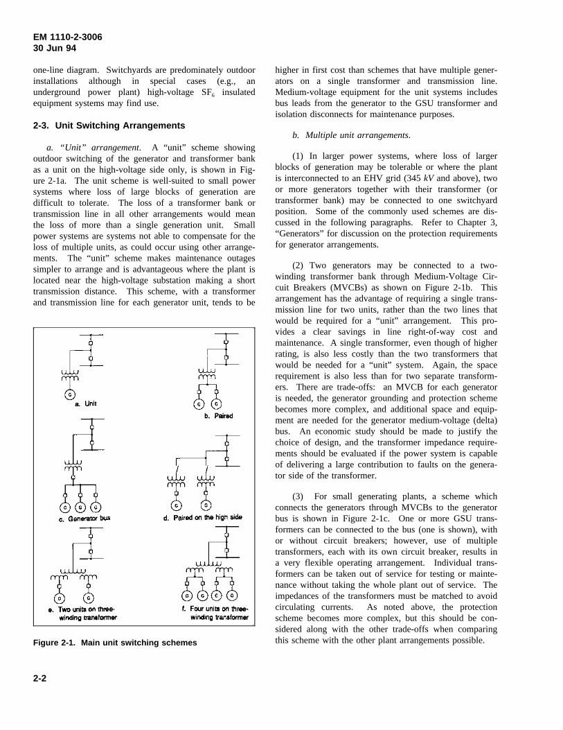
a. “Unit” arrangement. A “unit” scheme showingoutdoor switching of the generator and transformer bankas a unit on the high-voltage side only, is shown in Fig-ure 2-1a. The unit scheme is well-suited to small powersystems where loss of large blocks of generation aredifficult to tolerate. The loss of a transformer bank ortransmission line in all other arrangements would meanthe loss of more than a single generation unit. Smallpower systems are systems not able to compensate for theloss of multiple units, as could occur using other arrange-ments. The “unit” scheme makes maintenance outagessimpler to arrange and is advantageous where the plant islocated near the high-voltage substation making a shorttransmission distance. This scheme, with a transformerand transmission line for each generator unit, tends to be
Figure 2-1. Main unit switching schemes
higher in first cost than schemes that have multiple gener-ators on a single transformer and transmission line.Medium-voltage equipment for the unit systems includesbus leads from the generator to the GSU transformer andisolation disconnects for maintenance purposes.
b. Multiple unit arrangements.
(1) In larger power systems, where loss of largerblocks of generation may be tolerable or where the plantis interconnected to an EHV grid (345kV and above), twoor more generators together with their transformer (ortransformer bank) may be connected to one switchyardposition. Some of the commonly used schemes are dis-cussed in the following paragraphs. Refer to Chapter 3,“Generators” for discussion on the protection requirementsfor generator arrangements.
(2) Two generators may be connected to a two-winding transformer bank through Medium-Voltage Cir-cuit Breakers (MVCBs) as shown on Figure 2-1b. Thisarrangement has the advantage of requiring a single trans-mission line for two units, rather than the two lines thatwould be required for a “unit” arrangement. This pro-vides a clear savings in line right-of-way cost andmaintenance. A single transformer, even though of higherrating, is also less costly than the two transformers thatwould be needed for a “unit” system. Again, the spacerequirement is also less than for two separate transform-ers. There are trade-offs: an MVCB for each generatoris needed, the generator grounding and protection schemebecomes more complex, and additional space and equip-ment are needed for the generator medium-voltage (delta)bus. An economic study should be made to justify thechoice of design, and the transformer impedance require-ments should be evaluated if the power system is capableof delivering a large contribution to faults on the genera-tor side of the transformer.
(3) For small generating plants, a scheme whichconnects the generators through MVCBs to the generatorbus is shown in Figure 2-1c. One or more GSU trans-formers can be connected to the bus (one is shown), withor without circuit breakers; however, use of multipletransformers, each with its own circuit breaker, results ina very flexible operating arrangement. Individual trans-formers can be taken out of service for testing or mainte-nance without taking the whole plant out of service. Theimpedances of the transformers must be matched to avoidcirculating currents. As noted above, the protectionscheme becomes more complex, but this should be con-sidered along with the other trade-offs when comparingthis scheme with the other plant arrangements possible.
2-2
EM 1110-2-300630 Jun 94
(4) Two or more generators can be connected toindividual transformer banks through generator MVCBswith the transformers bused through disconnect switcheson the high-voltage side as shown in Figure 2-1d. Thisarrangement has some of the advantages of the “unit”system shown in Figure 2-1a, and discussed above, alongwith the advantage of fewer transmission lines, whichresults in less right-of-way needs. There is some loss ofoperational flexibility, since transmission line servicerequires taking all of the units out of service, and a linefault will result in sudden loss of a rather large block ofpower. Again, needs of the bulk power distribution sys-tem and the economics of the arrangement must beconsidered.
(5) Two or more generators may be connected to athree-winding transformer bank as shown in Figure 2-1eand f. The generators would be connected to the twolow-voltage windings through generator MVCBs. Thisarrangement allows specification of a low value of“through” impedance thus increasing the stability limits ofthe system and allowing the specification of a high valueof impedance between the two low-voltage GSU trans-former windings. This reduces the interrupting capacityrequirements of the generator breakers. This scheme isparticularly advisable when the plant is connected to abulk power distribution system capable of delivering highfault currents. Again, transformer or line faults will resultin the potential loss to the bulk power distribution systemof a relatively large block of generation. Transformermaintenance or testing needs will require loss of the gen-erating capacity of all four units for the duration of thetest or maintenance outage. This scheme finds applicationwhere plants are interconnected directly to an EHV grid.
2-4. Substation Arrangements
a. General. High-voltage substation arrangementsand application considerations are described in Chapter 5,“High-Voltage System.” High-voltage systems includethose systems rated 69kV and above. The plant switch-ing arrangement should be coordinated with the switch-yard arrangement to ensure that the resulting integrationachieves the design goals outlined in paragraph 2-1c in acost-effective manner.
b. Substation switching. Some plants may be electri-cally located in the power system so their transmissionline-voltage buses become a connecting link for two ormore lines in the power system network. This can requirean appreciable amount of high-voltage switching equip-ment. The desirability of switching small units at genera-tor voltage should nevertheless be investigated in such
cases. Chapters 5, “High-Voltage System” and 6,“Generator-Voltage System,” discuss switching and busarrangements in more detail.
2-5. Fault Current Calculations
a. General. Fault current calculations, using themethod of symmetrical components, should be preparedfor each one-line scheme evaluated to determine requiredtransformer impedances, generator and station switchgearbreaker interrupting ratings, and ratings of disconnectswitches and switchyard components. Conventional meth-ods of making the necessary fault current calculations andof determining the required ratings for equipment arediscussed in IEEE 242 and 399. A number of softwareprograms are commercially available for performing thesestudies on a personal computer. Two of these programsare: ETAP, from Operation Technology, Inc., 17870 Sky-park Circle, Suite 102, Irvine, CA 92714; and DAPPERand A-FAULT, from SKM Systems Analysis, Inc.,225 S Sepulveda Blvd, Suite 350, Manhattan Beach,CA 90266.
b. Criteria. The following criteria should be fol-lowed in determining values of system short-circuitcapacity, power transformer impedances, and generatorreactances to be used in the fault current calculations.
(1) System short-circuit capacity. This is theestimated maximum ultimate symmetricalkVA short-circuit capacity available at the high-voltage terminals ofthe GSU transformer connected to the generator underconsideration, or external to the generator under consider-ation if no step-up transformer is used. It includes theshort-circuit capacity available from all other generators inthe power plant in addition to the short-circuit capacity ofthe high-voltage transmission system. System short-circuit capacity is usually readily available from systemplanners of the utility or the PMA to which the plant willbe connected.
(2) Calculating system short-circuit capacity. Thetransmission system short-circuit capacity can also becalculated with reasonable accuracy when sufficient infor-mation regarding the planned ultimate transmission systemis available, including the total generating capacity con-nected to the system and the impedances of the varioustransmission lines that provide a path from the energysources to the plant.
(3) Estimating power system fault contribution.When adequate information regarding the transmissionsystem is unavailable, estimating methods must be used.
2-3
EM 1110-2-300630 Jun 94
In all cases, the system short-circuit capacity for use inthe fault current calculations should be estimated on aconservative basis, i.e., the estimate should be largeenough to allow for at least a 50-percent margin of errorin the system contribution. This should provide a factorof safety, and also allow for addition of transmission linesand generation capacity not presently planned or contem-plated by system engineers and planners. Only in excep-tional cases, such as small-capacity generating plants withonly one or two connecting transmission lines, should theestimated ultimate system short-circuitry capacity be lessthan 1,000MVA.
(4) Power transformer impedances.
(a) Actual test values of power transformerimpedances should be used in the fault calculations, ifthey are available. If test values are not available, designvalues of impedance, adjusted for maximum IEEE stan-dard minus tolerance (7.5 percent for two-winding trans-formers, and 10 percent for three-winding transformersand auto-transformers) should be used. Nominal designimpedance values are contained in Table 4-1 of Chap-ter 4, “Power Transformers.” For example, if the imped-ance of a two-winding transformer is specified to be8.0 percent, subject to IEEE tolerances, the transformerwill be designed for 8.0 percent impedance. However,the test impedance may be as low as 8.0 percent less a7.5-percent tolerance, or 7.4 percent, and this lower valueshould be used in the calculations, since the lower valueof impedance gives greater fault current.
(b) If the impedance of the above example trans-former is specified to be not more than 8.0 percent, thetransformer will be designed for 7.44 percent impedance,
so that the upper impedance value could be 7.998 percent,and the lower impedance value (due to the design toler-ance) could be as low as 6.88 percent, which is 7.44 per-cent less the 7.5 percent tolerance, which should be usedin the calculations because the lower value gives a higherfault current. Using the lower impedance value is a moreconservative method of estimating the fault current,because it anticipates a “worst case” condition. Imped-ances for three-winding transformers and auto-transform-ers should also be adjusted for standard tolerance inaccordance with the above criteria. The adjusted imped-ance should then be converted to an equivalent impedancefor use in the sequence networks in the fault current cal-culations. Methods of calculating the equivalent imped-ances and developing equivalent circuits are described inIEEE 242.
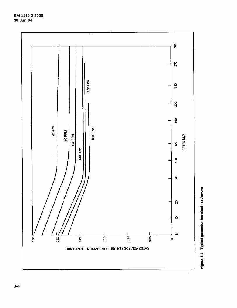
(5) Generator reactances. Actual test values ofgenerator reactances should also be used in the calcula-tions if they are available. If test values are not available,calculated values of reactances, obtained from the genera-tor manufacturer and adjusted to the appropriate MVAbase, should be used. Rated-voltage (saturated) values ofthe direct-axis transient reactance (X’d), the direct-axissubtransient reactance (X"d), and the negative-sequencereactance (X2), and the zero-sequence reactance (Xo), arethe four generator reactances required for use in the faultcurrent calculations. If data are not available, Figure 3-2in Chapter 3, “Generators,” provides typical values ofrated-voltage direct-axis subtransient reactance for water-wheel generators based on machine size and speed.Design reactance values are interrelated with other speci-fied machine values (e.g., short-circuit ratio, efficiency) sorevised data should be incorporated into fault computa-tions once a machine has been selected.
2-4
EM 1110-2-300630 Jun 94
Chapter 3Generators
3-1. General
a. Design constraints. Almost all of the hydraulic-turbine-driven generators used in Corps’ powerhouses willbe synchronous alternating-current machines, which pro-duce electrical energy by the transformation of hydraulicenergy. The electrical and mechanical design of eachgenerator must conform to the electrical requirements ofthe power distribution system to which it will be con-nected, and also to the hydraulic requirements of itsspecific plant. General Corps of Engineers waterwheelgenerator design practice is covered by the Guide Specifi-cation CW-16210.
b. Design characteristics. Since waterwheel genera-tors are custom designed to match the hydraulic turbineprime mover, many of the generator characteristics (e.g.,short-circuit ratio, reactances) can be varied over a fairlywide range, depending on design limitations, to suit spe-cific plant requirements and power distribution systemstability needs. Deviations from the nominal generatordesign parameters can have a significant effect on cost, soa careful evaluation of special features should be madeand only used in the design if their need justifies theincreased cost.
3-2. Electrical Characteristics
a. Capacity and power factor. Generator capacity iscommonly expressed in kilovolt-amperes (kVA), at a given(“rated”) power factor. The power factor the generatorwill be designed for is determined from a consideration ofthe electrical requirements of the power distribution sys-tem it will be connected to. These requirements include aconsideration of the anticipated load, the electrical loca-tion of the plant relative to the power system load centers,and the transmission lines, substations, and distributionfacilities involved. (See paragraph 3-2f).
b. Generator power output rating. The kilowattrating of the generator should be compatible with thehorsepower rating of the turbine. The most commonturbine types are Francis, fixed blade propeller, andadjustable blade propeller (Kaplan). See detailed discus-sion on turbine types and their selection and application inEM 1110-2-4205. Each turbine type has different operat-ing characteristics and imposes a different set of generatordesign criteria to correctly match the generator to theturbine. For any turbine type, however, the generator
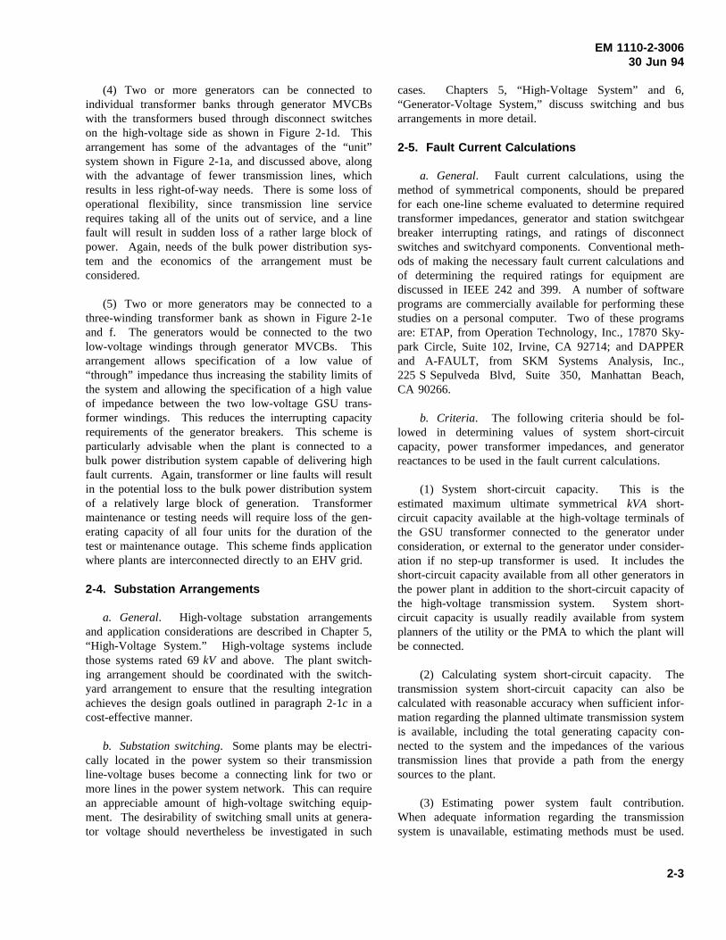
should have sufficient continuous capacity to handle themaximum horsepower available from the turbine at100-percent gate without the generator exceeding its ratednameplate temperature rise. In determining generatorcapacity, any possible future changes to the project, suchas raising the forebay level and increasing turbine outputcapability, should be considered. Figure 3-1 shows atypical capability curve for a hydroelectric generator.
Figure 3-1. Typical hydro-generator capability curve
c. Generator voltage. The voltage of large, slow-speed generators should be as high as the economy ofmachine design and the availability of switching equip-ment permits. Generators with voltage ratings in excessof 16.5 kV have been furnished, but except in specialcases, manufacturing practices generally dictate an uppervoltage limit of 13.8kV for machines up through250 MVA rating. Based on required generator reactances,size, andWk2, a lower generator voltage, such as 6.9kV,may be necessary or prove to be more economical thanhigher voltages. If the generators are to serve an estab-lished distribution system at generator voltage, then thesystem voltage will influence the selection of generatorvoltage, and may dictate the selection and arrangement ofgenerator leads also. Generators of less than 5,000kVAshould preferably be designed for 480 V, 2,400 V, or4,160 V, depending on the facilities connecting the gener-ator to its load.
3-1
EM 1110-2-300630 Jun 94
d. Insulation.
(1) The generator stator winding is normally suppliedwith either Class B or Class F insulation materials, withthe insulation system meeting the temperature limits andparameters of ANSI C50.12 (e.g., 75 °C rise above a40 °C ambient). The choice of insulation system typesdepends on machine size, how the machine will beoperated, and desired winding life. Modern hydro unitsare subjected to a wide variety of operating conditions butspecifications should be prepared with the intent ofachieving a winding life expectancy of 35 or more yearsunder anticipated operating conditions.
(2) The choice between Class B or Class F insulationsystems for the stator winding will depend on theexpected use of the generator. If it will be operated con-tinuously at or near rated load, or has a high probabilityof operating overloaded for longer than 2 hr at a time,then the Class F insulation system should be specified.For generators that can be expected to be operated belowrated load most of the time, and at or near full load foronly limited periods, a Class B insulation system wouldbe satisfactory. An insulation system using a polyesterresin as a binder should be considered a Class B system,since the softening temperature of polyester resin is closeto the Class F temperature limit.
(3) Stator winding insulation systems consist of agroundwall insulation, usually mica, with a suitable insu-lation binder, generally a thermosetting epoxy or polyestermaterial. These thermosetting systems achieve dielectricstrengths equivalent to that of older thermoplastic insula-tion systems with less thickness than the older systems,allowing the use of additional copper in a given statorslot, achieving better heat transfer, and permitting cooleroperation. Thermosetting insulation systems toleratehigher continuous operating temperatures than older sys-tems with less mechanical deterioration.
(4) Polyester resin has a lower softening temperature(known as the glass transition temperature, Tg) than themore commonly available epoxy insulation system, but ithas the advantage of being slightly more flexible than theepoxy system. This slight flexibility is an advantagewhen installing multi-turn coils in stator slots in smalldiameter generators. The plane of the coil side coincideswith the plane of the slot once the coil is installed. Dur-ing installation, however, the coil side approaches the slotat a slight angle so that the coil must be slightly distortedto make the side enter the slot. Polyester is less likely tofracture than epoxy when distorted during installation.Polyester has no advantage over epoxy if the stator
winding is of the Roebel bar type. Epoxy is usuallypreferred because of its higher Tg, and the polyester insu-lation system may not be available in the future.
(5) Thermosetting insulation system materials arehard and do not readily conform to the stator slot surface,so special techniques and careful installation proceduresmust be used in applying these materials. Corps guidespecification CW-16210 provides guidance on types ofwinding and coil fabrication techniques, and installation,acceptance, and maintenance procedures to be used toensure long, trouble-free winding life.
e. Short-circuit ratio.
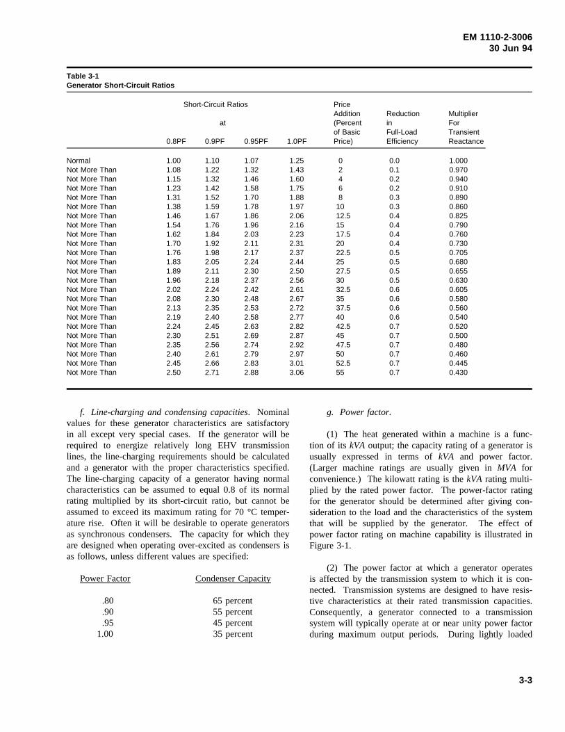
(1) The short-circuit ratio of a generator is the ratioof the field current required to produce rated open circuitvoltage, to the field current required to produce ratedstator current when the generator output terminals areshort-circuited. The short-circuit ratio is also the recipro-cal of the per unit value of the saturated synchronousreactance. The short-circuit ratio of a generator is a mea-sure of the transient stability of the unit, with higher ratiosproviding greater stability. Table 3-1 lists nominal short-circuit ratios for generators. Short-circuit ratios higherthan nominal values can be obtained without muchincrease in machine size, but large values of short-circuitratio must be obtained by trade-offs in other parameters ofgenerator performance. Increasing the short-circuit ratioabove nominal values increases the generator cost anddecreases the efficiency and the transient reactance.Included in Table 3-1 are expected price additions to thegenerator basic cost and reductions in efficiency andtransient reactance when higher than nominal short-circuitratio values are required.
(2) In general, the requirement for other than nomi-nal short-circuit ratios can be determined only from astability study of the system on which the generator is tooperate. If the stability study shows that generators at theelectrical location of the plant in the power system arelikely to experience instability problems during systemdisturbances, then higher short-circuit ratio values may bedetermined from the model studies and specified. If thepower plant design is completed and the generators pur-chased prior to a determination of the exterior systemconnections and their characteristics, i.e., before the con-necting transmission lines are designed or built, this willpreclude making a system study to accurately determinethe short-circuit ratio required. Where it is not feasible todetermine the short-circuit ratio and there are no factorsindicating that higher than nominal values are needed,then nominal short-circuit ratios should be specified.
3-2
EM 1110-2-300630 Jun 94
Table 3-1Generator Short-Circuit Ratios
Short-Circuit Ratios PriceAddition Reduction Multiplier
at (Percent in Forof Basic Full-Load Transient
0.8PF 0.9PF 0.95PF 1.0PF Price) Efficiency Reactance
Normal 1.00 1.10 1.07 1.25 0 0.0 1.000Not More Than 1.08 1.22 1.32 1.43 2 0.1 0.970Not More Than 1.15 1.32 1.46 1.60 4 0.2 0.940Not More Than 1.23 1.42 1.58 1.75 6 0.2 0.910Not More Than 1.31 1.52 1.70 1.88 8 0.3 0.890Not More Than 1.38 1.59 1.78 1.97 10 0.3 0.860Not More Than 1.46 1.67 1.86 2.06 12.5 0.4 0.825Not More Than 1.54 1.76 1.96 2.16 15 0.4 0.790Not More Than 1.62 1.84 2.03 2.23 17.5 0.4 0.760Not More Than 1.70 1.92 2.11 2.31 20 0.4 0.730Not More Than 1.76 1.98 2.17 2.37 22.5 0.5 0.705Not More Than 1.83 2.05 2.24 2.44 25 0.5 0.680Not More Than 1.89 2.11 2.30 2.50 27.5 0.5 0.655Not More Than 1.96 2.18 2.37 2.56 30 0.5 0.630Not More Than 2.02 2.24 2.42 2.61 32.5 0.6 0.605Not More Than 2.08 2.30 2.48 2.67 35 0.6 0.580Not More Than 2.13 2.35 2.53 2.72 37.5 0.6 0.560Not More Than 2.19 2.40 2.58 2.77 40 0.6 0.540Not More Than 2.24 2.45 2.63 2.82 42.5 0.7 0.520Not More Than 2.30 2.51 2.69 2.87 45 0.7 0.500Not More Than 2.35 2.56 2.74 2.92 47.5 0.7 0.480Not More Than 2.40 2.61 2.79 2.97 50 0.7 0.460Not More Than 2.45 2.66 2.83 3.01 52.5 0.7 0.445Not More Than 2.50 2.71 2.88 3.06 55 0.7 0.430
f. Line-charging and condensing capacities. Nominalvalues for these generator characteristics are satisfactoryin all except very special cases. If the generator will berequired to energize relatively long EHV transmissionlines, the line-charging requirements should be calculatedand a generator with the proper characteristics specified.The line-charging capacity of a generator having normalcharacteristics can be assumed to equal 0.8 of its normalrating multiplied by its short-circuit ratio, but cannot beassumed to exceed its maximum rating for 70 °C temper-ature rise. Often it will be desirable to operate generatorsas synchronous condensers. The capacity for which theyare designed when operating over-excited as condensers isas follows, unless different values are specified:
Power Factor Condenser Capacity
.80 65 percent
.90 55 percent
.95 45 percent1.00 35 percent
g. Power factor.
(1) The heat generated within a machine is a func-tion of its kVA output; the capacity rating of a generator isusually expressed in terms ofkVA and power factor.(Larger machine ratings are usually given inMVA forconvenience.) The kilowatt rating is thekVA rating multi-plied by the rated power factor. The power-factor ratingfor the generator should be determined after giving con-sideration to the load and the characteristics of the systemthat will be supplied by the generator. The effect ofpower factor rating on machine capability is illustrated inFigure 3-1.
(2) The power factor at which a generator operatesis affected by the transmission system to which it is con-nected. Transmission systems are designed to have resis-tive characteristics at their rated transmission capacities.Consequently, a generator connected to a transmissionsystem will typically operate at or near unity power factorduring maximum output periods. During lightly loaded
3-3
EM 1110-2-300630 Jun 94
3-4
EM 1110-2-300630 Jun 94
conditions, however, the generator may be required toassist in transmission line voltage regulation. A generatoroperating on an HV transmission system with relativelyshort transmission distances will typically be required tosupply reactive power (i.e., operate with a lagging powerfactor in an overexcited condition), due to the inductivecharacteristic of the unloaded transmission line. A gener-ator operated on a long, uncompensated EHV transmissionline will typically be required to absorb reactive power(i.e., operate with a leading power factor in an under-excited condition), due to the capacitive characteristic ofthe unloaded transmission line. In the latter case, thegenerator field current requirements are substantiallybelow rated field currents, thus reducing the generatorfield strength. With reduced field strength, the generatoroperates closer to its stability limit (see Figure 3-1), mak-ing it more susceptible to loss of synchronism or poleslipping in the event of a system disturbance.
(3) It is highly desirable that the generator bedesigned for the power factor at which it will operate inorder to improve system stability. In general, unlessstudies indicate otherwise, the power factor selectedshould be 0.95 for medium and large generators unlessthey will be at the end of a long transmission line, inwhich case a value approaching unity may be desirable.
h. Reactances.
(1) The eight different reactances of a salient-polegenerator are of interest in machine design, machine test-ing, and in system stability and system stability modelstudies. A full discussion of these reactances is beyondthe scope of this chapter, but can be found in electricalengineering texts (Dawes 1947; Fitzgerald and Kingsley1961; Puchstein, Lloyd, and Conrad 1954), and systemstability texts and standards (IEEE 399).
(2) Both rated voltage values of transient andsubtransient reactances are used in computations for deter-mining momentary rating and the interrupting ratings ofcircuit breakers. A low net through reactance of thegenerator and step-up transformer combined is desirablefor system stability. Where nominal generator and trans-former design reactances do not meet system needs, theincrease in cost of reducing either or both the generatorand transformer reactances and the selection of specialgenerator reactance should be a subject for economicstudy. Such a study must include a consideration ofspace and equipment handling requirements, since areduction in reactance may be accomplished by anincrease in generator height or diameter, or both.
(3) Typical values of transient reactances for largewater wheel generators indicated by Figure 3-2 are inaccordance with industry standard practice. Guaranteedvalues of transient reactances will be approximately10 percent higher.
(4) Average values of standard reactance will proba-bly be sufficiently close to actual values to determine therating of high-voltage circuit breakers, and should be usedin preliminary calculations for other equipment. As soonas design calculations for the specific machine are avail-able, the design values should be used in rechecking thecomputations for other items of plant equipment.
i. Amortisseur windings.
(1) Amortisseur windings (also referred to as damperwindings in IEEE 399; Dawes 1947; Fitzgerald and King-sley 1961; and Puchstein, Lloyd, and Conrad 1954) areessentially a short-circuited grid of copper conductors inthe face of each of the salient poles on a waterwheelgenerator. Two types of amortisseur windings may bespecified. In one, the pole face windings are not inter-connected with each other, except through contact withthe rotor metal. In the second, the pole face windings areintentionally connected at the top and bottom to the adja-cent damper windings.
(2) The amortisseur winding is of major importanceto the stable operation of the generator. While the gener-ator is operating in exact synchronism with the powersystem, rotating field and rotor speed exactly matched,there is no current in the damper winding and it essen-tially has no effect on the generator operation. If there isa small disturbance in the power system, and thefrequency tends to change slightly, the rotor speed and therotating field speed will be slightly different. The rotormass is perturbed when synchronizing power tends to pullthe rotor back into synchronism with the system. Thatperturbation tends to cause the rotor-shaft-turbine runnermass to oscillate about its average position as a torsionalpendulum. The result is relatively large pulsations in theenergy component of the generator current. In worst case,the oscillations can build instead of diminishing, resultingin the generator pulling out of step with possible conse-quential damage.
(3) At the onset of the oscillations, however, theamortisseur winding begins to have its effect. As therotating field moves in relation to the rotor, current isinduced in the amortisseur windings. Induction motor
3-5
EM 1110-2-300630 Jun 94
action results, and the rotor is pulled back toward syn-chronism by the amortisseur winding action.
(4) The amortisseur (damper) winding is of impor-tance in all power systems, but even more important tosystems that tend toward instability, i.e., systems withlarge loads distant from generation resources, and largeintertie loads.
(5) In all cases, connected amortisseur windings arerecommended. If the windings are not interconnected, thecurrent path between adjacent windings is through thefield pole and the rotor rim. This tends to be a highimpedance path, and reduces the effectiveness of thewinding, as well as resulting in heating in the currentpath. Lack of interconnection leads to uneven heating ofthe damper windings, their deterioration, and ultimatelydamage to the damper bars.
(6) The amortisseur winding also indirectly aids inreducing generator voltage swings under some fault condi-tions. It does this by contributing to the reduction of theratio of the quadrature reactance and the direct axis reac-tance, Xq"/Xd". This ratio can be as great as 2.5 for asalient pole generator with no amortisseur winding, andcan be as low as 1.1 if the salient pole generator has afully interconnected winding.
j. Efficiencies. The value of efficiency to be used inpreparing the generator specification should be as high ascan be economically justified and consistent with a valuemanufacturers will guarantee in their bids. Speed andpower factor ratings of a generator affect the efficiencyslightly, but the selection of these characteristics is gov-erned by other considerations. For a generator of anygiven speed and power factor rating, design efficienciesare reduced by the following:
(1) Higher Short-Circuit Ratio (see paragraph 3-2e).
(2) HigherWk2 (see paragraph 3-5b).
(3) Above-Normal Thrust.
Calculated efficiencies should be obtained from the sup-plier as soon as design data for the generators are avail-able. These design efficiencies should be used until testvalues are obtained.
3-3. Generator Neutral Grounding
a. General. The main reasons for grounding the neu-trals of synchronous generators are to limit overvoltages
on the generators and connected equipment under phase-to-ground fault conditions, and to permit the applicationof suitable ground fault relaying. Suitable neutral ground-ing equipment should be provided for each generator inhydroelectric power plants. The generator neutrals shouldbe provided with current-limiting devices in the neutralcircuits to limit the winding fault currents and resultingmechanical stresses in the generators in accordance withIEEE C62.92.2 requirements. Also, generator circuitbreakers are designed for use on high impedancegrounded systems, where the phase-to-ground short-circuitcurrent will not exceed 50A. High impedance groundingwith distribution transformers and secondary resistors isthe method of choice for waterwheel generators.
b. Choice of grounding method. The choice ofgenerator neutral grounding type for each installation, andthe selection of the most suitable type and rating of neu-tral grounding equipment, should be made after prepara-tion of fault current calculations and consideration of thefollowing factors:
(1) Limitation of winding fault current and resultingmechanical stresses in the generator.
(2) Limitation of transient overvoltages due toswitching operations and arcing grounds.
(3) Limitation of dynamic overvoltages to ground onthe unfaulted phases.
(4) Generator surge protection (see paragraph 3-4).
(5) Generator ground fault relaying (see para-graph 8-6b(3)).
(6) Limitation of damage at the fault.
(7) Neutral switchgear requirements.
(8) Cost of neutral grounding equipment.
c. Solid neutral grounding. Solid neutral groundingis the simplest grounding method, since transientovervoltages and overvoltages to ground on the unfaultedphases during phase-to-ground faults are held to a mini-mum. Solid neutral grounding does produce maximumground fault current and possible damage at the fault.Solid neutral grounding is not recommended.
d. Reactor neutral grounding. Reactor neutralgrounding has certain desirable characteristics similar tothose of solid neutral grounding. It is a preferred method
3-6
EM 1110-2-300630 Jun 94
of grounding in cases where a neutral current-limitingdevice is required to meet ANSI/IEEE short-circuitrequirements and where the ratio of the zero sequencereactance to the positive sequence subtransient reactanceat the fault does not exceed 6.0. Reactor neutral ground-ing limits transient overvoltages and overvoltages toground on the unfaulted phases to safe values where theabove reactance ratio does not exceed approximately 6.0.However, in most hydro applications, this reactance ratioapproaches or exceeds 6.0, and since the high impedancedistribution transformer-secondary resistor system is moreeconomical, reactor neutral grounding does not find wide-spread use in hydro applications.
e. Resistor neutral grounding. Resistor neutralgrounding can be considered in cases where solid neutralgrounding or reactor neutral grounding would not besatisfactory; where several generators are paralleled on acommon bus, especially in the case of generators of smallor medium kVA rating; and where there are no exposedoverhead feeders supplied at generator voltage. The resis-tor is usually rated to limit the generator neutral currentduring a phase-to-ground fault to a value between 100 and150 percent of the generator full-load current. Possibledamage at the fault is thus materially reduced, yet suffi-cient ground fault current is available to permit the appli-cation of satisfactory and selective ground fault relaying.The technique does produce high voltage to ground,exposing insulation systems of equipment connected tothe generator to the possibility of insulation failure.
f. Distribution transformer-secondary resistor neutralgrounding.
(1) This is the preferred method of generator neutralgrounding and is, in effect, high-resistance neutral ground-ing. This is the method used in most North Americanhydro installations because the cost of grounding devicesand neutral switchgear for other grounding methods isexcessive due to the large values of ground fault current.It is also applicable to generators connected directly todelta-connected windings of step-up power transformers,especially where there are no overhead feeders supplied atgenerator voltage. The characteristics of this method ofgrounding, with respect to transient overvoltages toground on the unfaulted phases and the requirement forthe use of ungrounded-neutral rated surge arresters forgenerator surge protection, are similar to those of resistorneutral grounding.
(2) With this method of grounding, the generatorneutral current, during a phase-to-ground fault, is limitedto a very low value, usually between 5A and 15A, by the
use of a relatively low-ohm resistor shunted across thesecondary of a conventional step-down transformer whoseprimary is connected in the generator neutral circuit. Thepossible damage at the fault is therefore least of any ofthe various grounding methods. However, the type ofgenerator ground fault relaying which can be applied hascertain disadvantages when compared to the relayingwhich can be used with other grounding methods. Due torelatively low relay sensitivity, a considerable portion ofthe generator windings near the neutral ends cannot beprotected against ground faults, the relaying is not selec-tive, and the relay sensitivity for ground faults external tothe generator varies greatly with the fault resistance andthe resistance of the return circuit for ground fault current.The kVA rating of the grounding transformer should bebased on the capacitive current which would flow duringa phase-to-ground fault with the generator neutralungrounded.
(3) Due to the relative infrequence and short dura-tion of ground faults, a rating of 25 to 100kVA is usuallyadequate for the transformer. The voltage rating of thetransformer high-voltage winding should be equal to ratedgenerator voltage, and the transformer low-voltage wind-ing should be rated 240 V. The rating of the secondaryresistor is based on making the resistorkW loss at leastequal to the capacitive faultkVA.
g. Generator neutral equipment.
(1) An automatic air circuit breaker should be pro-vided in the neutral circuit of each generator whose neu-tral is solidly grounded, reactor grounded, or resistorgrounded. The circuit breaker should be a metal-clad,drawout type, either 1-pole or 3-pole, with a voltage rat-ing at least equal to rated generator voltage, and withadequate ampere interrupting capacity, at rated voltage,for the maximum momentary neutral current during asingle phase-to-ground fault. For generator neutral ser-vice, the circuit breakers may be applied for interruptingduties up to 115 percent of their nameplate interruptingratings. When 3-pole breakers are used, all poles shouldbe paralleled on both line and load sides of the breaker.
(2) A single-pole air-break disconnect should beprovided in each generator neutral circuit using distribu-tion transformer-secondary resistor type grounding. Thedisconnect should have a voltage rating equal to ratedgenerator voltage, and should have the minimum availablemomentary and continuous current ratings. Thedisconnect, distribution transformer, and secondary resis-tor should be installed together in a suitable metal enclo-sure. The distribution transformer should be of the dry
3-7
EM 1110-2-300630 Jun 94
type, and its specifications should require a type of insula-tion that does not require a heater to keep moisture out ofthe transformer.
3-4. Generator Surge Protection
a. Surge protection equipment. Since hydroelectricgenerators are air-cooled and physically large, it is neitherpractical nor economical to insulate them for as highimpulse withstand level as oil-insulated apparatus of thesame voltage class. Because of this and the relative costof procuring and replacing (or repairing) the stator wind-ing, suitable surge protection equipment should be pro-vided for each generator. The equipment consists ofspecial surge arresters for protection against transientovervoltage and lightning surges, and special capacitorsfor limiting the rate of rise of surge voltages in additionto limiting their magnitude.
b. Insulation impulse level. The impulse level of thestator winding insulation of new generators isapproximately equal to the crest value of the factory low-frequency withstand test voltage, or about 40.5kV for13.8-kV generators. The impulse breakdown voltages forsurge arresters for 13.8-kV generator protection areapproximately 35kV for 12-kV grounded-neutral ratedarresters, and approximately 44kV for 15 kV ungrounded-neutral rated arresters. Grounded-neutral rated surgearresters therefore provide better protection to generatorsthan ungrounded-neutral rated arresters.
c. Grounded-neutral rated arresters. To correctlyapply grounded-neutral rated arresters without an unac-ceptable risk of arrester failure, the power-frequencyvoltage applied across the arrester under normal or faultconditions must not exceed the arrester voltage rating.This requirement is usually met if the ratio of zerosequence reactance to positive sequence subtransient reac-tance at the fault, for a single phase-to-ground fault, doesnot exceed approximately 6.0. Since distribution trans-former-secondary resistor grounding does not meet thisrequirement, only ungrounded-neutral rated surge arrestersshould be applied for generator surge protection.
d. Arrester arrangement. In most cases, one surgearrester and one 0.25-microfarad surge capacitor are con-nected in parallel between each phase and ground. Incertain cases, however, such as the condition where thegenerators supply distribution feeders on overhead lines atgenerator voltage, or where two or more generators willbe operated in parallel with only one of the generator
neutrals grounded, two of the above capacitors per phaseshould be provided. A separate set of surge protectionequipment should be provided for each generator. Theequipment should be installed in metal enclosures locatedas close to the generator terminals as possible.
3-5. Mechanical Characteristics
The section of Guide Specification CW-16120 coveringmechanical characteristics of the generator provides forthe inclusion of pertinent data on the turbine. Since gen-erator manufacturers cannot prepare a complete proposalwithout turbine characteristics, the generator specificationis not advertised until data from the turbine contract areavailable.
a. Speeds.
(1) Hydraulic requirements fix the speed of the unitwithin rather narrow limits. In some speed ranges, how-ever, there may be more than one synchronous speedsuitable for the turbine, but not for the generator becauseof design limitations.
(2) Generators below 360r/min and 50,000kVA andsmaller are nominally designed for 100 percent overspeed.Generators above 360r/min and smaller than 50,000kVAare generally designed for 80 percent overspeed. Genera-tors larger than 50,000kVA, regardless of speed, aredesigned for 85 percent overspeed. Because of the highoverspeed of adjustable blade (Kaplan) turbines, in somecases more than 300 percent of normal, it may be imprac-ticable to design and build a generator to nominal designlimitations. Where overspeeds above nominal values areindicated by the turbine manufacturer, a careful evaluationof the operating conditions should be made. Also, thedesigner should be aware that turbine and generator over-speed requirements are related to the hydraulic character-istics of the unit water inlet structures. Hydraulictransients that might result from load rejections or suddenload changes need to be considered.
(3) Generators for projects with Kaplan turbineshave been designed for runaway speeds of 87-1/2 percentof the theoretical maximum turbine speed. In accordancewith requirements of Guide Specification CW-16120, thestresses during design runaway speeds should not exceedtwo-thirds of the yield point. However, where the designoverspeed is less than the theoretical maximum runawayspeed, calculated stresses for the theoretical maximumspeed should be less than the yield points of the materials.
3-8
EM 1110-2-300630 Jun 94
b. Flywheel effect.
(1) The flywheel effect (Wk²) of a machine isexpressed as the weight of the rotating parts multiplied bythe square of the radius of gyration. TheWk² of thegenerator can be increased by adding weight in the rim ofthe rotor or by increasing the rotor diameter. Increasingthe Wk² increases the generator cost, size, and weight, andlowers the efficiency. The need for above-normalWk²should be analyzed from two standpoints, the effect onpower system stability, and the effect on speed regulationof the unit.
(2) Electrical system stability considerations may inspecial cases require a highWk² for speed regulation. AsWk² is only one of several adjustable factors affectingsystem stability, all factors in the system design should beconsidered in arriving at the minimum overall cost. Suffi-cient Wk² must be provided to prevent hunting and affordstability in operation under sudden load changes. Theindex of the relative stability of generators used in electri-cal system calculations is the inertia constant,H, which isexpressed in terms of stored energy perkVA of capacity.It is computed as:
H = kW s = 0.231 (Wk²) (r/min)² x 10-6
kVA kVA
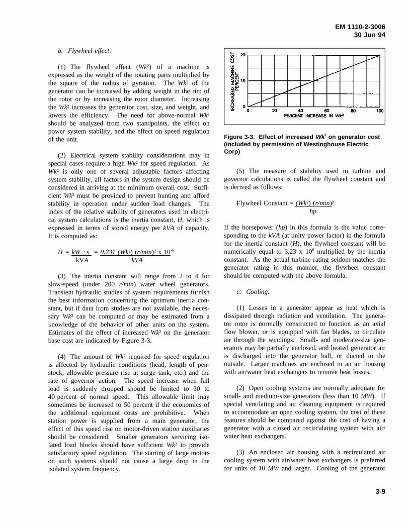
(3) The inertia constant will range from 2 to 4 forslow-speed (under 200r/min) water wheel generators.Transient hydraulic studies of system requirements furnishthe best information concerning the optimum inertia con-stant, but if data from studies are not available, the neces-sary Wk² can be computed or may be estimated from aknowledge of the behavior of other units on the system.Estimates of the effect of increasedWk² on the generatorbase cost are indicated by Figure 3-3.
(4) The amount ofWk² required for speed regulationis affected by hydraulic conditions (head, length of pen-stock, allowable pressure rise at surge tank, etc.) and therate of governor action. The speed increase when fullload is suddenly dropped should be limited to 30 to40 percent of normal speed. This allowable limit maysometimes be increased to 50 percent if the economics ofthe additional equipment costs are prohibitive. Whenstation power is supplied from a main generator, theeffect of this speed rise on motor-driven station auxiliariesshould be considered. Smaller generators servicing iso-lated load blocks should have sufficientWk² to providesatisfactory speed regulation. The starting of large motorson such systems should not cause a large drop in theisolated system frequency.
Figure 3-3. Effect of increased Wk2 on generator cost(included by permission of Westinghouse ElectricCorp)
(5) The measure of stability used in turbine andgovernor calculations is called the flywheel constant andis derived as follows:
Flywheel Constant =(Wk²) (r/min)²hp
If the horsepower (hp) in this formula is the value corre-sponding to thekVA (at unity power factor) in the formulafor the inertia constant (H), the flywheel constant will benumerically equal to 3.23 x 10⁶ multiplied by the inertiaconstant. As the actual turbine rating seldom matches thegenerator rating in this manner, the flywheel constantshould be computed with the above formula.
c. Cooling.
(1) Losses in a generator appear as heat which isdissipated through radiation and ventilation. The genera-tor rotor is normally constructed to function as an axialflow blower, or is equipped with fan blades, to circulateair through the windings. Small- and moderate-size gen-erators may be partially enclosed, and heated generator airis discharged into the generator hall, or ducted to theoutside. Larger machines are enclosed in an air housingwith air/water heat exchangers to remove heat losses.
(2) Open cooling systems are normally adequate forsmall- and medium-size generators (less than 10MW). Ifspecial ventilating and air cleaning equipment is requiredto accommodate an open cooling system, the cost of thesefeatures should be compared against the cost of having agenerator with a closed air recirculating system with air/water heat exchangers.
(3) An enclosed air housing with a recirculated aircooling system with air/water heat exchangers is preferredfor units of 10MW and larger. Cooling of the generator
3-9
EM 1110-2-300630 Jun 94
can be more easily controlled with such a system, and thestator windings and ventilating slots in the core keptcleaner, reducing the rate of deterioration of the statorwinding insulation system. The closed system also per-mits the addition of automatic fire protection systems,attenuates generator noise, and reduces heat gains thatmust be accommodated by the powerhouse HVACsystem.
(4) Water-cooled heat exchangers used in a recircu-lated air cooling system consist of groups of thin-walledfinned tubes with appropriate water boxes, valves, andheaders. Standard air coolers are designed for 50-pound-per-square-inch (psi) working pressure, but can be sup-plied for 100-psi working pressure for a slightly higherprice. The 100-psi rated coolers should be used wherethe hydraulic head of the cooling water source is greaterthan 100 ft. For best service, tube sheets of 90/10 Cu/Nishould be used for air and bearing lube oil coolers. Theturbine spiral case is normally used as the cooling watersource for projects with heads of up to 250 ft. Whereproject head exceeds approximately 250 ft, pumped sys-tems using a tailwater source are preferred.
(5) The design pressure for the stator heat exchangersshould be based on pump shut-off head if a pumpedsource of cooling water is used. Design pressure forspiral case cooling water sources should be based onmaximum project pool level, plus a surge allowance.Heat exchanger hydrostatic tests should be performed atpressures of 150 percent of rated pressure. Design cool-ing water temperature should be the maximum tempera-ture of the cooling water source, plus a contingencyallowance.
(6) The water supply line to the air coolers should beseparate from the water line to the thrust-bearing cooler.It may prove desirable to modulate the water flow to theair coolers to control the generator temperature, or to shutit off entirely when the unit is being stopped. It is desir-able to keep a full flow of water through the thrust bear-ing oil cooler whenever the unit is turning. Each coolingwater supply line should be equipped with a flow indica-tor. The flow indicator should be equipped with an alarmcontact for low flow.
(7) Each air cooler should be equipped with watershut-off valves so a cooler can be cut out if in trouble, orbe serviced while the generator is operating. Coolersshould be designed with as great a number of heatexchanger tubes in the air flow passage as practical inorder to reduce water usage. Adequate floor drains insidethe air housing should be provided to remove any water
that may condense on or leak from the coolers. The unitdrain header should empty into the tailwater if plant con-ditions permit, but the drain should not be terminatedwhere it will be subject to negative pressures from thedraft tube, since this will impose negative pressures onthe heat exchangers.
(8) Heated air from the generator enclosure shouldnot be used for plant space heating because of the possi-bility of exposure of plant personnel to ozone, and thepossibility of CO2 being discharged into the plant. Waterfrom the coolers may be used as a heat source in a heatpump type of heating system, but if water flow modula-tion is used, there may not be enough heat available dur-ing periods of light loading, or when the plant is shutdown.
d. Weights and dimensions.
(1) Estimating weights and dimensions of the gener-ators should be obtained from generator manufacturers forplant design purposes. These figures should be recheckedafter bid data are available on the particular generatorselected. The contemplated speed,Wk², short-circuit ratio,reactance, and over-speed are the usual factors that havethe greatest effect on weight variation. Where a highvalue Wk² is required, a machine of the next larger framesize with consequent increase in diameter may berequired.
(2) Dimensions of the rotor and the method ofassembling the rotor and the shaft in the generator havean important bearing on crane clearances. The numberand location of air coolers and the shape of the air hous-ing on a generator with the closed type of cooling systemshould be studied for their effect on the dimensions of thegenerator room. Generator and turbine access should beconsidered, as well as the possible need for suppressingnoise radiated into the powerhouse.
3-6. Excitation Systems
a. General. Current practice in the design of Corpsof Engineers power plants is to use solid state bus-fedexcitation systems for the generator exciter and voltageregulator function. Solid state excitation systems cur-rently available from reputable manufacturers exhibitreliability comparable to, and in some cases better than,older mechanical systems. Excitation system specifica-tions should be carefully prepared, with attention torequirements of the power system to which the generatorwill be connected.
3-10
EM 1110-2-300630 Jun 94
b. Large generators.
(1) The stability of a large turbine-generator set whileconnected to its power system is critically important.However, the designer must also consider the unit’s char-acteristics when operating alone, or in an isolated “island”much smaller than the normal power system.
(2) One example of a unit operating alone is a mainunit serving as the station service source in a plant thatbecomes separated from its power distribution system.The unit will have to accept motor starting loads, andother station service demands such as gate and valveoperation, while maintaining a safe and stable outputvoltage and frequency. All this will be accomplishedwhile operating at a fraction of its rated output.
(3) When operating in an “island,” the unit may berequired to operate in parallel with other units while run-ning at speed-no-load in order to provide enough capacityto pick up blocks of load without tripping off line. In thiscase, stable operation without the stabilizing effect of avery large system is critically important to restoring ser-vice, and putting the system back together.
c. Small units. For small units producing energy fora very large system, stability is not so critical since sys-tem voltage support will be beyond the small unit’s capa-bility. Nonetheless, for its own safe operation, goodvoltage control is important. An extremely high responsesystem is not necessary, but the system should respondrapidly enough to prevent dangerous voltage excursions.
d. Excitation system characteristics.
(1) In general, there are two types of static excitationsystems: one using a full-inverting power bridge, and theother using a semi-inverting power bridge. The full-inverting system uses six (or more) silicon controlledrectifiers (SCRs) in the power bridge so the generatorfield voltage can be forced both positive and negative.The semi-inverting system allows the generator fieldvoltage to be forced positive, and reduced to zero.
(2) The full-inverting bridge allows boost and buckoperation much like that available in older systems, butwith the potential for a faster response. Faster responsemeans less phase shift in the control action, and thereduction of phase shift permits control action to increasethe stability of voltage regulation (see alsoparagraph 3-6g(6)).
(3) Dips in output voltage can be reduced, and volt-age recovery speed improved, with the field forcing func-tion. Increasing the field voltage helps greatly inovercoming the lag caused by the inductance of the gener-ator field, and increases the speed of response of genera-tor output voltage to control action. However, the exciterceiling voltage (maximum forcing voltage available) tothe generator field must be limited to a value that will notdamage field insulation. The manufacturer will determinethe exciter ceiling voltage based on the nominal responsespecified.
(4) The semi-inverting system also provides for fastresponse, but without the capability to force the fieldvoltage negative with respect to its normal polarity. Thisslows the generator output voltage response capability.One or more diodes provide a path for decaying fieldcurrent when the AC contactor is opened.
(5) Power system requirements and machine voltageperformance during unit load rejections should be consid-ered in evaluating the use of a semi-inverting system. Ifstability requirements can be met and adequate voltageperformance maintained during unit load rejections, theneither a semi-inverting or a full-inverting system isacceptable. If either criterion appears compromised, afull-inverting system is recommended.
(6) If the particular generator (or plant) in questionhas sufficient capacity to affect the control area to whichit is connected, a full-inverting voltage regulating systemwould be justified if the control area has a high ratio ofenergy import (or export) to load, and is marginally stableor experiences tie line separations. A full-inverting sys-tem can force voltage down if an export tie line is lost,and can force generator voltage down if the machine issuddenly tripped off line while carrying a substantial load.Both cases will reduce voltage stresses on the generator;the first example will assist in maintaining systemstability, the second will help protect the generator wind-ing from dangerous overvoltages.
e. Excitation system arrangement.
(1) In general, bus-fed solid state excitation systemsare made up of three elements: the power potential trans-former (PPT), the power bridge (or rectifier), and thecontrol section (voltage regulator function).
(2) Location of the PPT will depend on the supplysource chosen. If power to the PPT is supplied from the
3-11
EM 1110-2-300630 Jun 94
generator leads, the bus arrangement will be affected, andthat must be considered in the initial design and layout ofthe powerhouse. If the PPT is fed from the generatordelta bus, its location must be selected so that it will bereasonably close to the power bridge equipment. ThePPT should be specified to be self-cooled, and thedesigner should consider this in determining its location.
(3) For either power source to the PPT, protectionshould be provided by current-limiting fuses. The avail-able fault current at the input to the PPT will be quitelarge, so it will be necessary to limit it to prevent destruc-tive releases of energy at the fault location. Current-limit-ing fuses also provide circuit clearing without currentsurges that can cause voltage transients which are danger-ous to the integrity of the generator insulation. When thefusible element melts, the fuse essentially becomes aresistor in series with the fault. Voltage and currentacross the resistor are thus in phase, and the circuit iscleared at the first zero crossing, without danger of arcrestrike (if the fuse works properly).
(4) The excitation system should also provide for ameans of disconnecting power from the generator field.In general, this requires that power be interrupted at thebridge input, at the generator field input, or at both places,and that a means of dissipating energy stored in the fieldbe provided. Energy dissipation is a major consideration,because without it the field inductance will cause fieldvoltage to rise sharply when field current is interrupted,possibly rupturing the field insulation. Several methodsexist to perform the field removal function.
(a) One method of field removal for a semi-invertingsystem uses a contactor in the AC input to the powerbridge. For field discharge, a diode (called a free-wheeling diode) can be used to provide a path for thefield current to dissipate field energy. Another method isto provide a shorting contact in series with a dischargeresistor across the generator field. When the Device 41AC breaker opens, the auxiliary Device 41 shorting con-tact closes.
(b) A method which can be used with a full-invertingbridge uses a field breaker and discharge resistor. This isa straightforward method where the power from thebridge to the field is interrupted, and the field issimultaneously short-circuited through a discharge resistor.
(c) With either a semi- or full-inverting bridge, it ispossible to use a device 41 in the DC side of the bridge,with a thyristor element to control field energydissipation. The thyristor device is a three- (or more)
junction semiconductor with a fast OFF to ON switchingtime that is capable of going to the conducting statewithin a very short time (about one quarter of a cycle)after the Device 41 opens.
(d) With either a semi- or full-inverting bridge, it ispossible to use a device 41 in the AC (input) side of thebridge, with a thyristor element to control field energydissipation. The thyristor device is a three- (or more)junction semiconductor with a fast OFF to ON switchingtime that is capable of going to the conducting statewithin a very short time (about one quarter of a cycle)after the Device 41 opens.
(5) Power bridge equipment should be housed in acubicle by itself, for safety and reduction of electromag-netic noise, and be located near or beside the excitationcontrol cubicle. Both cubicles should be designed forreduction of radiated electromagnetic interference (EMI).
(6) The power electronics equipment in the excita-tion system can be either fan-cooled or self-cooled.Fan-cooled excitation systems are usually smaller thanself-cooled systems, but require extra equipment for thelead-lag fan controls. Fan-cooled excitation systems mayrequire additional maintenance resulting from such thingsas fans failing to start, air flow switches failing, fan airflow causing oil from the turbine pit to be deposited onfilters, and worn-out fan motors causing noise to beapplied to the regulator control system. Self-cooledexcitation systems may require larger cubicles and higher-rated equipment to allow for heat transfer. On largegenerators, it may not be practical to use a self-cooledsystem. On smaller units it may be preferable. Each unitshould be judged on its life cycle costs.
(7) If the capability of connecting a unit to ade-energized transmission system will be necessary(“black start” capability), there may be a requirement foroperating the generator at around 25 percent of nominalvoltage to energize transformers and transmission lineswithout high inrush currents. This requirement mayimpose the need for an alternate power source to the PPTsince the power bridge might not operate reliably atreduced voltage levels. If an alternate supply source isneeded, provide switching and protection, and ensure thatthe normal PPT source and the emergency source cannotbe connected in parallel. The power transmission author-ity should be consulted to determine the voltage necessaryfor charging lines and transformers to re-energize a powersystem. Requiring additional power sources not only addscosts to the project, but complexity to the system, whichmay not be justified. The complexity of a system is
3-12
EM 1110-2-300630 Jun 94
usually proportional to its maintenance, failure, and mis-operation rate.
f. Excitation system regulators.
(1) The voltage regulator function of modern solidstate excitation equipment is an integral part of the sys-tem, and will use digital control elements with micropro-cessor-based control. This type of control provides farmore flexibility in changing regulator characteristics thanthe older mechanical element type of control. It alsoprovides more precise and predictable control action, andwill require far less maintenance.
(2) The voltage regulator function should provideautomatic and manual control of generator output voltage,with “bumpless” transfer between modes, over a range ofat least plus or minus 10 percent from nominal generatorvoltage. The bumpless transfer requirement means thatthe regulator control modes must track each other so thatwhen the control mode is switched the generator voltage(or reactive output) will not exhibit a step change of anymagnitude.
(3) Voltage regulator control to maintain generatorpower factor, or maintain a selected var loading may alsobe required. If the plant is to have an automatic controlsystem, provisions should be required for control inputs tothe regulator, and it may be possible to dispense withsome of the regulator control features, particularly if theplant will not be manned.
g. Excitation system accessories.
(1) An AC input voltmeter, a DC output (field volt-age) voltmeter, and a DC field ammeter are accessoriesthat should be considered essential for a quick check onsystem operation. Rectifier failure detection should alsobe considered, particularly for units controlled remotely.
(2) Remotely operated controls are also essential forunits controlled from locations remote from the unitswitchboards. Maximum and minimum excitation limiterequipment should also be provided in all cases. Thisequipment is critical to units that are direct connectedwith other units on a common bus.
(3) Momentary connection of a DC source of properpolarity to the generator field (field flashing) should alsobe required. Field flashing provides prompt and reliablebuildup of generator voltage without reliance on residualmagnetism. Include protection against overlong applica-tion of the flashing source. The simplest source for field
flashing voltage is the station battery. If the unit is notrequired to have black start capability, an alternative tousing the station battery is to use an AC power sourcewith a rectifier to furnish the necessary DC power forfield flashing. This alternative source could be consideredif it is determined to be significantly more economicalthan providing additional station battery capacity.Depending on the design, this alternative could requireadditional maintenance in the long term for short-termcost reductions. Project life cost should be consideredwhen evaluating the sources of field flashing. A rectifiercan be used as the DC source if the station battery sizecan be reduced enough to provide economic justification.
(4) Reactive droop compensation equipment isneeded for units operated in parallel on a common low-voltage bus to prevent unequal sharing of reactive load.Reactive droop compensation reduces the generator outputvoltage slightly as reactive output increases. The neteffect is to stabilize unit operation when operating inparallel and tending to prevent var load swings betweenunits.
(5) Active droop compensation (or “line drop” com-pensation) is simply a means of artificially relocating thepoint where the generator output voltage is sensed for thevoltage regulation function. It consists of increasing thegenerator output voltage in proportion to output current, tocompensate for the voltage drop between the generatoroutput terminals and the desired point on the system.Active droop compensation should be considered if thegenerator is connected to the system through a highimpedance unit transformer or to a long high-impedancetransmission line. Line drop compensation is usually notrequired unless needed for power transmission systemvoltage stability. This requirement will be established bythe power transmission authority. When used with auto-matic voltage control that derives its controlled-valueinput from the same, or nearly the same, point as the linedrop compensation feature, caution should be used toensure that the automatic voltage control system is notcounteracting the effects of the voltage regulator line dropcompensation feature. Close coordination with the powertransmission authority is required to ensure power systemvoltage stability.
(6) Power System Stabilizer (PSS) equipment shouldbe used on generators large enough to have a positiveeffect on power system stability. The PSS function tendsto damp out generator rotor oscillations by controlling theexcitation system output in phase opposition to powersystem oscillations to damp them out. PSS works bysensing an input from the power system and reacting to
3-13
EM 1110-2-300630 Jun 94
oscillations in the power system. These oscillations typi-cally show up in the unit as rotor angle oscillations and ifallowed to continue to build up in conjunction with othersynchronous machines in the system, set up unacceptablepower swings between major loads and major generatingplants in a widely dispersed power distribution grid.
h. Excitation system instrument transformers. Dedi-cated current and potential transformers should be sup-plied to service the excitation system voltage regulators.They can often be advantageously mounted in metal-cladswitchgear, cubicles, or metal-enclosed bus runs, wherethey are associated with similar instrument transformersfor metering and relay service. The latter are furnishedand mounted by the manufacturer of the cubicles orbuses, and a better layout can usually be devised, whereall instrument transformers are of the same general form,than would result if space were provided for field installa-tion of transformers supplied with the voltage regulator.Multiple-secondary current transformers save considerablespace. The guide specifications provide for alternatemethods of procurement, assuming that the general designof buses and generator leads will have been determinedbefore the generator is awarded.
3-7. Generator Stator
a. Stator core stampings. The stator primary compo-nent is the thin sheet steel stampings that, when stackedtogether and clamped, form the stator core. The stampingshapes are so designed that when they are correctlystacked, they will form stator winding coil slots, with nostamping protruding into the slot. Uneven slots are detri-mental to coil life in several ways: wear on ground wallinsulation armor tape; prevention of adequate tighteningof coil in the slot; and, in extreme cases, erosion of theground wall insulation.
b. Stator frame.
(1) The stator frame is designed for rigidity andstrength to allow it to support the clamping forces neededto retain the stator punchings in the correct core geome-try. Strength is needed for the core to resist deformationunder fault conditions and system disturbances. Also, thecore is subjected to magnetic forces that tend to deform itas the rotor field rotates. In a few large size machines,this flexing has been known to cause the core to contactthe rotor during operation. In one instance, the coredeformed and contacted the rotor, the machine wastripped by a ground fault, and intense heating caused localstator tooth iron melting, which damaged the stator wind-ing ground wall insulation.
(2) Even if the rotor and the stator core do not comein contact, the varying air gap is a problem. In machineswith split phase windings where the split phase currentsare monitored for machine protection, the variation in theair gap causes a corresponding variation in the split phasecurrents. If the variations are significant, the machinewill trip by differential relay action, or the differentialrelays will have to be desensitized to prevent tripping.Desensitizing the relays will work, but it reduces theireffectiveness in protecting the machine from internalfaults.
(3) Further reading on this subject can be found inthe IEEE Transactions on Power Apparatus and Systems,Vol PAS-102, Nos. 9 and 10, and in the AIEE Transac-tions of October 1953, as Paper 53-314.
c. Stator assembly. Small stator assemblies that canbe shipped in one or two pieces should be completelyassembled at the factory. If the stator frame assembly hasto be shipped in more than two pieces, the core shouldprobably be stacked in the field. Field stacking will avoidsplits in the stator core, the major source of stator coreproblems. Stator frames are generally built at the factoryin sections that are as large as can be shipped to the erec-tion site. Stator assembly is completed in the field bybolting the sections together, stacking the core iron lamin-ations, and winding the stator. Field stacking of the statorcore results in a higher initial cost for the generator, butprovides better service life and is preferred. GeneratorGuide Specification CW-16120 contains a discussion onstator assembly.
d. Multiturn coil stator windings. On smaller gener-ators, and on certain sizes of larger machines, stator wind-ings employing multiple turn coils are used. Thiseffectively inserts more coils per armature slot, giving ahigher generated voltage per slot as compared with asingle turn bar winding. With this winding design, thestator winding is divided into two or more parallel pathsper phase. On the neutral ends of the winding, one halfof each phase is connected to the ground point through acurrent transformer (CT) of carefully selected ratio andcharacteristics. On the generator output, other CTs mea-sure the total phase current. Differential relays comparethe split phase current and total phase current; an internalgenerator fault that results in unbalanced current betweenthe phase halves can usually be detected and the unittripped off quickly enough to prevent serious damage.
e. Roebel bar stator windings. For large generators,winding designs using single turn coils are preferred, inwhich case the neutral terminals are not divided and a
3-14
EM 1110-2-300630 Jun 94
different arrangement of CTs for the differential relays isrequired. The single turn coils use a Roebel transposition,rather than separate turns, to balance current in the con-ductors. This eliminates the possibility of turn-to-turnfaults, which are a common cause of winding failures.Single turn coils cannot be used on machines with shortbore heights because there is not sufficient room to makethe Roebel transposition. There are also certain configu-rations of large machines which do not allow the use ofsingle turn coils.
3-8. Rotor and Shaft
a. Rotor assembly.
(1) Large generator rotors must be assembled in thepowerhouse. Manufacturing practice provides two types,one in which the hub and arms are made of cast steel, theother with a cast or fabricated hub to which are boltedand keyed the fabricated rotor arms. For rotors withbolted-on arms, a means of access to inspect andre-tighten the bolts should be specified. Some medium-sized units have been built with rotors of stacked sheets,but this type is limited by the rolling width of the sheets.With both types the rotor rim is built up of sheet steelpunchings.
(2) Pole pieces, assembled and wound in the factory,are usually made with a dovetail projection to fit slots inthe rim punchings. The pole pieces are assembled to therotor using wedge-shaped keys, two keys per pole piece.The field assembly program should make provisions forhandling large pole pieces without tying up the power-house bridge crane.
b. Generator shafts.
(1) Generator shafts 12-in. and larger diameter shouldbe gun-barrel drilled full length. This bore facilitatesinspection of the shaft forging, and in the case of Kaplanunits, provides a passage for the two oil pipes to the bladeservo-motor in the turbine shaft.
(2) Generators designed with the thrust bearinglocated below the rotor usually have either a boltedconnection between the bottom of the rotor hub and aflange on the shaft, or the shaft projects through a hole inthe hub and is keyed to it. Provisions in the powerhousefor rotor erection should consider the floor loading of therotor weight, concentrated on the area of the shaft hub orthe rotor flange, supported by the powerhouse floor.Include a plate in the floor (included with the generatorspecifications and to be supplied by the generator
manufacturer) to which the rotor hub or shaft flange canbe bolted.
(3) If the design of the rotor and shaft provides for apermanent connection between the shaft and rotor hub, itmay be necessary to locate the rotor erection plate in afloor recess, or on a pedestal on the floor below the erec-tion space, under a hole in the floor provided for theshaft. Also, if the complete rotor is to be assembled on along shaft which extends below the rotor hub before theshaft and rotor are placed in the stator, it may be conve-nient to provide a hole in the erection floor so that thelower end of the shaft will rest on the floor below, thusminimizing the crane lift during rotor assembly. Whenthe shaft must be handled with the rotor in assembling thegenerator, the crane clearance above the stator frame maybe affected.
3-9. Brakes and Jacks
The brakes, which are used to stop rotation of the unit,are actuated by 100-psi air pressure and are designed toserve as rotor jacks when high-pressure oil is substitutedfor air. As far as the generator alone is concerned, thedistance the rotor is to be lifted by the jacks depends onthe space required to change a thrust bearing shoe.Blocks should be provided to hold the rotor in the raisedposition without depending on the jacks. The usual liftrequired to service a bearing is approximately 2 in. If thegenerator is to be driven by a Kaplan turbine, the liftmust provide space for disconnecting the Kaplan oil pip-ing. This lift may be as much as 12 in. The generatormanufacturer can usually design for this extra lift sonothing on the generator need be disturbed except toremove the collector brush rigging. Motor-operated jack-ing oil pumps can be permanently connected to largeunits. Medium-sized and smaller generators can beserved with a portable motor-operated oil pump. Motor-operated pumps should be provided with suitable oilsupply and sump tanks so the oil system will be completeand independent of the station lubricating oil system.
3-10. Bearings
a. Thrust bearing loading. The thrust bearing in thegenerator is the most important bearing element in thegenerator-turbine assembly as it carries not only theweight of the rotating generator parts, but the weight ofthe turbine shaft and turbine runner, in addition to thehydraulic thrust on the runner. The allowable hydraulicthrust provided in standard generator design is satisfactoryfor use with a Francis runner, but a Kaplan runnerrequires provision for higher-than-normal thrust loads. It
3-15
EM 1110-2-300630 Jun 94
is important that the generator manufacturer have full andaccurate information regarding the turbine.
b. Thrust bearing types. The most commonly usedtypes of thrust bearings are the Kingsbury, the modifiedKingsbury, and the spring-supported type. The sphericaltype of thrust bearing has not been used on any Corps ofEngineers’ generators. All of these types have the bear-ing parts immersed in a large pot of oil that is cooledeither by water coils immersed in the oil or by the oilpumped through a heat-exchanger mounted near the bear-ing. These various types of bearings are fully describedin available texts, such as “The Mechanical Engineers’Handbook” (Marks 1951) and “Mechanical Engineers’Handbook” (Kent 1950).
c. Thrust bearing lubrication. The basic principle ofoperation of all bearing types requires a film of oilbetween the rotating bearing plate and the babbitted sta-tionary shoes. The rotating parts on some machines areso heavy that when the machine is shut down for a fewhours, the oil is squeezed out from between the bearingsurfaces and it is necessary to provide means to get oilbetween the babbitted surface and the bearing plate beforethe unit is started. Specifications for generators above10 MW, and for generators in unmanned plants, shouldrequire provisions for automatically pumping oil underhigh pressure between the shoes and the runner plate ofthe thrust bearing just prior to and during machine startup,and when stopping the machine.
d. Guide bearings. A guide bearing is usually pro-vided adjacent to the thrust bearing and is lubricated bythe oil in the thrust bearing pot. Except for Kaplan units,machines with guide bearings below the rotor seldomrequire an upper guide bearing. When the thrust bearingis above the rotor, a lower guide bearing is required.Two guide bearings should always be provided on genera-tors for use with Kaplan turbines. These separate guidebearings have self-contained lubricating systems. Oil inthe bearings seldom needs to be cleaned or changed, butwhen cleaning is necessary, the preferred practice is tocompletely drain and refill the unit when it is shut down.Valves on oil drains should be of the lock-shield type tominimize possibility of accidental draining of the oilduring operation.
3-11. Temperature Devices
a. Types of temperature devices. All generator andturbine bearings are specified to have three temperaturesensing devices: a dial-type indicating thermometer withadjustable alarm contacts, embedded resistance
temperature detector (RTD) devices, and a temperaturerelay (Device 38). The dial portions of the indicatingthermometers are grouped on a panel which can be part ofthe governor cabinet, mounted on the generator barrel, oron another panel where they can be easily seen by main-tenance personnel or a roving operator.
b. Dial indicator alarms. The dial indicator alarmcontacts are set a few degrees above the normal bearingoperating temperatures to prevent nuisance alarms. Whenapproaching their alarm setpoint, these contacts tend tobounce and chatter. If they are used with event recorders,they can produce multiple alarms in rapid successionunless some means are used to prevent this.
c. RTDs. RTD leads are brought out to terminalblocks, which are usually mounted in the generator termi-nal cabinet on the generator air housing. Turbine bearingRTD leads should be terminated in the same place as thegenerator RTD leads. For bearings equipped with morethan one RTD, it is usually adequate to monitor only one,and let the other(s) serve as spares. Thrust bearings mayhave six or more RTDs. Monitoring three or four ofthem is usually satisfactory. Generator stator windingsusually have several RTDs per phase. On the largermachines, monitor two RTDs per phase, and keep theremainder as spares.
d. RTD monitoring. How the RTDs are useddepends partly on the decisions made about the plantcontrol system. They can be scanned by the analog inputsection of a remote terminal unit (RTU) if the plant iscontrolled remotely, or they can be used as inputs to alocal stand-alone scanner system, with provisions forremote alarms and tripping the unit on high temperatures.In any case, permanent records of bearing temperaturesare no longer retained.
e. Control action. Whether to alarm or trip on RTDtemperature indication depends on other decisions abouthow the plant will be controlled, and what kind of controlsystem is used. For automated plants, stator temperatureincreases can be used as an indication to reduce unit loadautomatically, for instance.
f. Air temperature indicators. Air temperature indi-cators in air cooler air streams are used to balance thecooling water flow, and to detect cooler problems. Airtemperature alarms should be taken to the control point,or input to the plant control system if the plant isautomated.
3-16
EM 1110-2-300630 Jun 94
g. Temperature relays. Temperature relays are typi-cally used to shut the unit down on high bearing tempera-tures, 105 °C or so. Separate contacts should also beprovided for alarming. Note that once a bearing tempera-ture reaches the trip point, the damage has been done. Itis almost never possible to save the bearing. Tripping theunit promptly is done to save damage to other parts of theunit resulting from failure of the bearing. Temperaturerelay alarm points should be taken to the annunciator, andto the RTU or plant control system. It is not necessary toprovide sequence of event recording for the Device 38because the bearing temperature event is such a slowprocess.
3-12. Final Acceptance Tests
a. General. Because of the size of water wheel gen-erators, they are normally assembled in the field, andbecause of their custom design, it is advisable to performa series of acceptance and performance tests on the gener-ators during and following their field assembly. Thepurpose of these tests is to ensure that the units meetcontractual performance guarantees, to provide a qualitycontrol check of field assembly work, and finally to pro-vide a “bench mark” of “as-built” conditions serving as anaid in future maintenance and repair activities. Certainfield tests are performed on every generator of a serial(multi-unit) purchase; other tests are performed on onlyone unit of the serial purchase, e.g., tests for ensuringconformance with contractual guarantees.
b. Field acceptance tests and special field tests.These tests are as follows:
(1) Field quality control tests (all units). A series ofdielectric and insulation tests for the stator and field wind-ings, performed during field work, including turn-to-turntests, coil transposition group tests, and semiconductingslot coating-to-stator iron resistance tests, to monitor fieldassembly techniques.
(2) Field acceptance tests (all units). These testsconsist of:
(a) Stator dielectric tests. These tests consist of:Insulation resistance and polarization index, Corona probetest, Corona visibility test, Final AC high potential test,Partial discharge analysis (PDA) test, and Ozone detection(optional).
(b) Rotor dielectric tests.
(c) Stator and rotor resistance tests.
(3) Special field test (one unit of serial). These testsconsist of:
(a) Efficiency tests.
(b) Heat run tests.
(c) Machine parameter tests.
(d) Excitation test.
(e) Overspeed tests (optional).
c. Testing considerations.
(1) Planning for tests on the generator after itsinstallation should begin prior to completion of the gener-ator specifications. Any generator that must be assembledin the powerhouse will require field testing after installa-tion to measure values of efficiency and reactances, par-ticularly when efficiency guarantees are included in thepurchase specifications. The generator manufacturerperforms these tests with a different crew from thoseemployed for generator erection. Specification CW 16120requires a second generator in the powerhouse with spe-cial switching equipment and “back-fed” excitation systemto permit performing retardation tests used to determinegenerator efficiency. In addition, special arrangements arerequired to use one of the generator-voltage class breakersas a shorting breaker during sudden short-circuit tests.
(2) The manufacturer requires considerable advancenotice of desirable testing dates in order to calibrate testinstruments and ship in necessary switchgear and excita-tion equipment. If the associated turbine is to be given afield efficiency test, it may be desirable to coordinate theturbine and generator tests so that the electrical testinginstruments will be available to measure generator outputduring the turbine test. The heat run requires a load onthe generator. Normally, the generator is loaded by con-necting the generator output to the system load. If systemload isn’t sufficient to load the generator, IEEE 115 out-lines alternative techniques to simulate load conditions.
(3) The testing engineer may elect to use the plantinstrument transformers instead of calibrated current andpotential transformers if reliable data on plant instrumenttransformers are available.
(4) Generator erectors usually apply dielectric testson the armature (stator) and field windings before therotor is put into the machine. If the stator is wound inthe field, a high potential test is usually done once each
3-17
EM 1110-2-300630 Jun 94
day on all of the coils installed during that day. Thisfacilitates repairs if the winding fails under test and maypreclude missing scheduled “on-line” dates. The testvoltages for these intermediate tests must be planned sothat each one has a lower value than the previous test, butgreater than the test voltage specified for the final highpotential test.
(5) IEEE 43 describes the polarization index test.This index is the ratio of the insulation resistance obtainedwith a 10-min application of test voltage to that obtainedwith a similar application for a 1-minute period. Recom-mended indices and recommended insulation resistancevalues are also given in the referenced standard.
(b) Because of the relatively small amount of insula-tion on the field windings, simple insulation (Megger)tests are adequate to determine their readiness for thehigh-voltage test. Guide Specification CW-16120 requiresthe dielectric test to be made with the field winding con-nected to the collector rings and hence the test cannot bemade until after the generator is assembled with the DCleads of the static excitation system connected.
3-13. Fire Suppression Systems
Generators with closed air recirculation systems should beprovided with automatic carbon dioxide extinguishingsystems. See Chapter 15 of EM 1110-2-4205 for details.On larger open ventilated generators, water spray installa-tions with suitable detection systems to prevent falsetripping should be considered.
3-18
EM 1110-2-300630 Jun 94
Chapter 4Power Transformers
4-1. General
a. Type. Step-up transformers for use with mainunits should be of the oil immersed type for outdooroperation, with a cooling system as described in para-graph 4-3, suited to the location. General Corps of Engi-neers power transformer design practice is covered byGuide Specification for Civil Works ConstructionCW-16320.
b. Three-phase transformers. In the majority ofapplications, three-phase transformers should be used forgenerator step-up (GSU) applications for the followingreasons:
(1) Higher efficiency than three single-phase units ofequivalent capacity.
(2) Smaller space requirements.
(3) Lower installed cost.
(4) Lower probability of failure when properly pro-tected by surge arresters, thermal devices, and oil preser-vation systems.
(5) Lower total weight.
(6) Reduction in weights and dimensions makinglarger capacities available within practical weight and sizelimitations.
c. EHV applications. In applications involving inter-connection to EHV (345kV and above) systems, reliabil-ity and application considerations dictate the use ofsingle-phase units due to lack of satisfactory industryexperience with three-phase EHV GSU transformers. Thebasic switching provisions discussed in Chapter 2 describethe low-voltage switching scheme used with EHVtransformers.
d. Transformer features. Regardless of windingconfiguration, for any given voltage andkVA rating, withnormal temperature rise, the following features should beanalyzed for their effect on transformer life cycle costs:
(1) Type of cooling.
(2) Insulation level of high-voltage winding.
(3) Departure from normal design impedance.
Examples of typical transformer studies which should beperformed are contained in Appendix B of this manual.
e. Transformer construction. There are two types ofconstruction used for GSU transformers. These are thecore form type and the shell form type. Core form trans-formers generally are supplied by manufacturers for lowervoltage and lowerMVA ratings. The core form unit isadaptable to a wide range of design parameters, is eco-nomical to manufacture, but generally has a lowkVA-to-weight ratio. Typical HV ranges are 230kV and less and75 MVA and less. Shell form transformers have a highkVA-to-weight ratio and find favor on EHV and highMVA applications. They have better short-circuit strengthcharacteristics, are less immune to transit damage, buthave a more labor-intensive manufacturing process. Bothforms of construction are permitted by Corps’ transformerguide specifications.
4-2. Rating
The full loadkVA rating of the step-up transformer shouldbe at least equal to the maximumkVA rating of the gen-erator or generators with which they are associated.Where transformers with auxiliary cooling facilities havedual or triple kVA ratings, the maximum transformerrating should match the maximum generator rating.
4-3. Cooling
a. General. The standard classes of transformer cooling systems are listed in Paragraph 5.1, IEEE C57.12.00.Transformers, when located at the powerhouse, should besited so unrestricted ambient air circulation is allowed.The transformer rating is based on full use of the trans-former cooling equipment.
b. Forced cooling. The use of forced-air coolingwill increase the continuous self-cooled rating of thetransformer 15 percent for transformers rated 2499kVAand below, 25 percent for single-phase transformers rated2500 to 9999 kVA and three-phase transformers rated2500 to 11999kVA, and 33-1/3 percent for single-phasetransformers rated 10000kVA and above and three-phasetransformers rated 12000kVA and above. High-velocityfans on the largest size groups will increase the self-cooled rating 66-2/3 percent. Forced-oil cooled trans-formers, whenever energized, must be operated with thecirculating oil pumps operating. Forced-oil transformerswith air coolers do not have a self-cooled rating without
4-1
EM 1110-2-300630 Jun 94
the air-cooling equipment in operation unless they arespecial units with a “triple rating.”
c. Temperature considerations. In determining thetransformer rating, consideration should be given to thetemperature conditions at the point of installation. Highambient temperatures may necessitate increasing the trans-former rating in order to keep the winding temperaturewithin permissible limits. If the temperatures will exceedthose specified under “Service Conditions” in IEEEC57.12.00, a larger transformer may be required. IEEEC57.92 should be consulted in determining the ratingrequired for overloads and high temperature conditions.
d. Unusual requirements. Class OA/FA and ClassFOA meet all the usual requirements for transformerslocated in hydro plant switchyards. The use of triple-rated transformers such as Class OA/FA/FA is seldomrequired unless the particular installation services a loadwith a recurring short time peak.
e. Class FOA transformers. On Class FOA trans-formers, there are certain considerations regarding staticelectrification (build-up of charge on the transformerwindings due to oil flow). Transformer suppliers requireoil pump operation whenever an FOA transformer isenergized. Static electrification is important to considerwhen designing the desired operation of the cooling, andcan result in the following cooling considerations:
(1) Decrease in oil flow velocity requirements (forforced-oil cooled units).
(2) Modifying of cooling equipment controls to havepumps come on in stages.
(3) Operation of pumps prior to energizingtransformer.
4-4. Electrical Characteristics
a. Voltage.
(1) Voltage ratings and ratios should conform toANSI C84.1 preferred ratings wherever possible. Thehigh-voltage rating should be suitable for the voltage ofthe transmission system to which it will be connected,with proper consideration for increases in transmissionvoltage that may be planned for the near future. In somecases this may warrant the construction of high-voltagewindings for series or parallel operation, with bushingsfor the higher voltage, or windings suitable for the highervoltage tapped for the present operating voltage.
(2) Consideration should also be given to the voltagerating specified for the low-voltage winding. For plantsconnected to EHV systems, the low-voltage windingrating should match the generator voltage rating tooptimally match the generator’s reactive capability in“bucking” the transmission line voltage. For 230-kVtransmission systems and below, the transformer low-voltage rating should be 5 percent below the generatorvoltage rating to optimally match the generator’s reactivecapability when “boosting” transmission line voltage.IEEE C57.116 and EPRI EL-5036, Volume 2, providefurther guidance on considerations in evaluating suitablevoltage ratings for the GSU transformer.
b. High-voltage BIL.
(1) Basic Impulse Insulation Levels (BIL) associatedwith the nominal transmission system voltage are shownin Table 1 of IEEE C57.12.14. With the advent of metaloxide surge arresters, significant economic savings can bemade in the procurement of power transformers by speci-fying reduced BIL levels in conjunction with the applica-tion of the appropriate metal oxide arrester for transformersurge protection. To determine appropriate values, aninsulation coordination study should be made (see Appen-dix B for a study example). Studies involve coordinatingand determining adequate protective margins for the fol-lowing transformer insulation characteristics:
(a) Chopped-Wave Withstand (CWW).
(b) Basic Impulse Insulation Level (BIL).
(c) Switching Surge Level (SSL).
(2) If there is reason to believe the transmissionsystem presently operating with solidly grounded neutralsmay be equipped with regulating transformers or neutralreactors in the future, the neutral insulation level shouldbe specified to agree with Table 7 of IEEE C57.12.00.
c. Impedance.
(1) Impedance of the transformers has a materialeffect on system stability, short-circuit currents, and trans-mission line regulation, and it is usually desirable to keepthe impedance at the lower limit of normal impedancedesign values. Table 4-1 illustrates the range of valuesavailable in a normal two-winding transformer design(values shown are for GSU transformers with
4-2
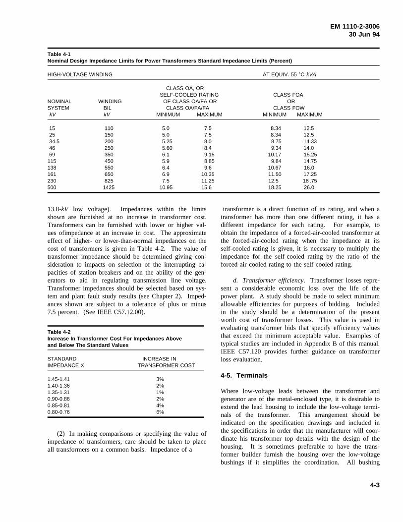
EM 1110-2-300630 Jun 94
Table 4-1Nominal Design Impedance Limits for Power Transformers Standard Impedance Limits (Percent)
HIGH-VOLTAGE WINDING AT EQUIV. 55 °C kVA
CLASS OA, ORSELF-COOLED RATING CLASS FOA
NOMINAL WINDING OF CLASS OA/FA OR ORSYSTEM BIL CLASS OA/FA/FA CLASS FOWkV kV MINIMUM MAXIMUM MINIMUM MAXIMUM
15 110 5.0 7.5 8.34 12.525 150 5.0 7.5 8.34 12.534.5 200 5.25 8.0 8.75 14.3346 250 5.60 8.4 9.34 14.069 350 6.1 9.15 10.17 15.25
115 450 5.9 8.85 9.84 14.75138 550 6.4 9.6 10.67 16.0161 650 6.9 10.35 11.50 17.25230 825 7.5 11.25 12.5 18 .75500 1425 10.95 15.6 18.25 26.0
13.8-kV low voltage). Impedances within the limitsshown are furnished at no increase in transformer cost.Transformers can be furnished with lower or higher val-ues ofimpedance at an increase in cost. The approximateeffect of higher- or lower-than-normal impedances on thecost of transformers is given in Table 4-2. The value oftransformer impedance should be determined giving con-sideration to impacts on selection of the interrupting ca-pacities of station breakers and on the ability of the gen-erators to aid in regulating transmission line voltage.Transformer impedances should be selected based on sys-tem and plant fault study results (see Chapter 2). Imped-ances shown are subject to a tolerance of plus or minus7.5 percent. (See IEEE C57.12.00).
Table 4-2Increase In Transformer Cost For Impedances Aboveand Below The Standard Values
STANDARD INCREASE INIMPEDANCE X TRANSFORMER COST
1.45-1.41 3%1.40-1.36 2%1.35-1.31 1%0.90-0.86 2%0.85-0.81 4%0.80-0.76 6%
(2) In making comparisons or specifying the value ofimpedance of transformers, care should be taken to placeall transformers on a common basis. Impedance of a
transformer is a direct function of its rating, and when atransformer has more than one different rating, it has adifferent impedance for each rating. For example, toobtain the impedance of a forced-air-cooled transformer atthe forced-air-cooled rating when the impedance at itsself-cooled rating is given, it is necessary to multiply theimpedance for the self-cooled rating by the ratio of theforced-air-cooled rating to the self-cooled rating.
d. Transformer efficiency. Transformer losses repre-sent a considerable economic loss over the life of thepower plant. A study should be made to select minimumallowable efficiencies for purposes of bidding. Includedin the study should be a determination of the presentworth cost of transformer losses. This value is used inevaluating transformer bids that specify efficiency valuesthat exceed the minimum acceptable value. Examples oftypical studies are included in Appendix B of this manual.IEEE C57.120 provides further guidance on transformerloss evaluation.
4-5. Terminals
Where low-voltage leads between the transformer andgenerator are of the metal-enclosed type, it is desirable toextend the lead housing to include the low-voltage termi-nals of the transformer. This arrangement should beindicated on the specification drawings and included inthe specifications in order that the manufacturer will coor-dinate his transformer top details with the design of thehousing. It is sometimes preferable to have the trans-former builder furnish the housing over the low-voltagebushings if it simplifies the coordination. All bushing
4-3
EM 1110-2-300630 Jun 94
characteristics should conform to the requirements ofIEEE C57.19.01. The voltage rating should correspond tothe insulation level of the associated winding. Wheretransformers are installed at elevations of more than3,300 ft above sea level, bushings of the next highervoltage classification may be required. Bushings forneutral connections should be selected to suit the insula-tion level of the neutral, as discussed in paragraph 4-4.
4-6. Accessories
a. Oil preservation systems. Three different oil pres-ervation systems are available, as described below. Thefirst two systems are preferred for generator step-uptransformers:
(1) Inert gas pressure system. Positive nitrogen gaspressure is maintained in the space between the top of theoil and the tank cover from a cylinder or group of cylin-ders through a pressure-reducing valve.
(2) Air-cell, constant-pressure, reservoir tank system.A system of one or more oil reservoirs, each containingan air cell arranged to prevent direct contact between theoil and the air.
(3) Sealed tank. Gas is admitted to the space abovethe oil and the tank is sealed. Expansion tanks for thegas are provided on some sizes. Sealed tank constructionis employed for 2,500kVA and smaller sizes.
b. Oil flow alarm. Transformers that depend uponpumped circulation of the oil for cooling should beequipped with devices that can be connected to sound analarm, to prevent closing of the energizing power circuit,or to deenergize the transformer with loss of oil flow. Inforced-oil-cooled units, hot spot detectors should be pro-vided which can be connected to unload the transformer ifthe temperature exceeds that at which the second oilpump is expected to cut in. FOA transformers shouldemploy control schemes to ensure pump operation prior toenergizing the transformer.
c. Surge arresters. Surge arresters are located nearthe transformer terminals to provide protection of thehigh-voltage windings. Normal practice is to providebrackets on the transformer case (230-kV HV and below)for mounting the selected surge arrester.
d. Fans and pumps. The axial-flow fans provided forsupplementary cooling on Class OA/FA transformers areequipped with special motors standardized for 115-V and230-V single-phase or 208-V three-phase operation. Like-
wise, oil circulating pumps for FOA transformers are setup for single-phase AC service. Standard Corps of Engi-neers practice is to supply 480-V, three-phase power tothe transformer and have the transformer manufacturerprovide necessary conversion equipment.
e. On-line dissolved gas monitoring system.Thedetection of certain gases, generated in an oil-filled trans-former in service, is frequently the first available indica-tion of possible malfunction that may eventually lead tothe transformer failure if not corrected. The monitoringsystem can provide gas analysis of certain gases from gasspaces of a transformer. The system output contacts canbe connected for an alarm or to unload the transformer ifthe gas levels exceed a set point. The type of gases gen-erated, during the abnormal transformer conditions, isdescribed in IEEE C57.104.
f. Temperature detectors. A dial-type temperatureindicating device with adjustable alarm contacts should beprovided for oil temperature indication. Winding RTDsshould be provided, and monitored by the plant controlsystem or a stand-alone temperature recorder, if one isprovided for the generator and turbine RTDs. At leasttwo RTDs in each winding should be provided.
g. Lifting devices. If powerhouse cranes are to beused for transformer handling, the manufacturer’s designof the lifting equipment should be carefully coordinatedwith the crane clearance and with the dimensions of thecrane hooks. The lifting equipment should safely clearbushings when handling the completely assembled trans-former, and should be properly designed to compensatefor eccentric weight dispositions of the complete trans-former with bushings.
h. On-line monitoring systems. In addition to theon-line dissolved gas monitoring system described inparagraph 4-6e, other on-line systems are available tomonitor abnormal transformer conditions. These include:
(1) Partial discharge analysis.
(2) Acoustical monitoring.
(3) Fiber-optic winding temperature monitoring.
(4) Bearing wear sensor (forced-oil-cooled units).
(5) Load tap changer monitor (if load tap changersare used).
4-4
EM 1110-2-300630 Jun 94
Early detection of the potential for a condition leading toa forced outage of a critical transformer bank could morethan offset the high initial costs of these transformeraccessories by avoiding a more costly loss of generation.
i. Dial-type indicating devices. Dial-type indicatingdevices should be provided for:
(1) Liquid level indication.
(2) Liquid temperature indicator.
(3) Oil flow indicators (see paragraph 4-6b).
These are in addition to the dial-type indicators that arepart of the winding temperature systems (seeparagraph 4-6f).
4-7. Oil Containment Systems
If any oil-filled transformers are used in the power plant,provisions are made to contain any oil leakage or spillageresulting from a ruptured tank or a broken drain valve.The volume of the containment should be sufficient toretain all of the oil in the transformer to prevent spillageinto waterways or contamination of soil around the trans-former foundations. Special provisions (oil-water separa-tors, oil traps, etc.) must be made to allow for separationof oil spillage versus normal water runoff from storms,etc. IEEE 979 and 980 provide guidance on design con-siderations for oil containment systems.
4-8. Fire Suppression Systems
a. General. Fire suppression measures and protectiveequipment should be used if the plant’s oil-filled
transformers are located in close proximity to adjacenttransformers, plant equipment, or power plant structures.Oil-filled transformers contain the largest amount of com-bustible material in the power plant and so require dueconsideration of their location and the use of fire suppres-sion measures. Fires in transformers are caused primarilyfrom breakdown of their insulation systems, althoughbushing failures and surge arrester failures can also becauses. With failure of the transformer’s insulation sys-tem, internal arcing follows, creating rapid internal tankpressures and possible tank rupture. With a tank rupture,a large volume of burning oil may be expelled over alarge area, creating the possibility of an intense fire.
b. Suppression measures. Suppression measuresinclude the use of fire quenching pits or sumps filled withcoarse rock surrounding the transformer foundation andphysical separation of the transformer from adjacentequipment or structures. Physical separation in distance isalso augmented by the use of fire-rated barriers or by fire-rated building wall construction when installation preventsmaintaining minimum recommended separations. Eco-nomical plant arrangements generally result in less thanrecommended minimums between transformers and adja-cent structures so water deluge systems are supplied as afire prevention and suppression technique. The systemsshould be of the dry pipe type (to prevent freeze-up incold weather) with the system deluge valves actuatedeither by thermostats, by manual break-glass stations nearthe transformer installation, or by the transformer differ-ential protective relay.
4-5
EM 1110-2-300630 Jun 94
Chapter 5High-Voltage System
5-1. Definition
The high-voltage system as treated in this chapter includesall equipment and conductors that carry current at trans-mission line-voltage, with their insulators, supports,switching equipment, and protective devices. The systembegins with the high-voltage terminals of the step-uppower transformers and extends to the point where trans-mission lines are attached to the switchyard structure.High-voltage systems include those systems operating at69 kV and above, although 34.5-kV and 46-kV systemsthat are subtransmission-voltage systems are also coveredin this chapter. Transmission line corridors from thepowerhouse to the switchyard should allow adequateclearance for maintenance equipment access, and clearworking space. Working clearances shall be in accor-dance with the applicable sections of ANSI C2, Part 2.
5-2. Switchyard
a. Space around the switchyard. Adequate spaceshould be allowed to provide for extension of the switch-yard facilities when generating units or transmission linesare added in the future. The immediate surroundingsshould permit the building of lines to the switchyard areafrom at least one direction without the need for heavydead-end structures in the yard.
b. Switchyard location. Subject to these criteria, theswitchyard should be sited as near to the powerhouse asspace permits, in order to minimize the length of controlcircuits and power feeders and also to enable use of ser-vice facilities located in the powerhouse.
c. Switchyard fencing. A chain link woven wirefence not less than 7 ft high and topped with three strandsof barbed wire slanting outward at a 45-deg angle, or con-certina wire, with lockable gates, should be provided toenclose the entire yard. Other security considerations arediscussed in EM 1110-2-3001.
5-3. Switching Scheme
The type of high-voltage switching scheme should beselected after a careful study of the flexibility and protec-tion needed in the station for the initial installation, andalso when the station is developed to its probable maxi-mum capacity. A detailed discussion of the advantages
and disadvantages of various high-voltage switchingschemes is included in this chapter.
a. Minimum requirements. The initial installationmay require only the connecting of a single transformerbank to a single transmission line. In this case, one cir-cuit breaker, one set of disconnects with groundingblades, and one bypass disconnecting switch should beadequate. The high-voltage circuit breaker may even beomitted under some conditions. The receiving utilitygenerally establishes the system criteria that will dictatethe need for a high side breaker.
b. Bus structure. When another powerhouse unit ortransmission line is added, some form of bus structurewill be required. The original bus structure should bedesigned with the possibility of becoming a part of theultimate arrangement. Better known arrangements are themain and transfer bus scheme, the ring bus scheme, thebreaker-and-a-half scheme, and the double bus-doublebreaker scheme.
c. Main and transfer bus scheme.
(1) The main and transfer bus scheme, Figure 5a,consists of two independent buses, one of which is nor-mally energized. Under normal conditions, all circuits aretied to the main bus. The transfer bus is used to provideservice through the transfer bus tie breaker when itbecomes necessary to remove a breaker from service.
(2) Advantages of the main and transfer bus arrange-ment include:
(a) Continuity of service and protection during brea-ker maintenance.
(b) Ease of expansion.
(c) Small land area requirements.
(d) Low cost.
(3) Disadvantages include:
(a) Breaker failure or bus fault causes the loss of theentire station.
(b) Bus tie breaker must have protection schemes tobe able to substitute for all line breakers.
(c) An additional tie breaker is required.
5-1
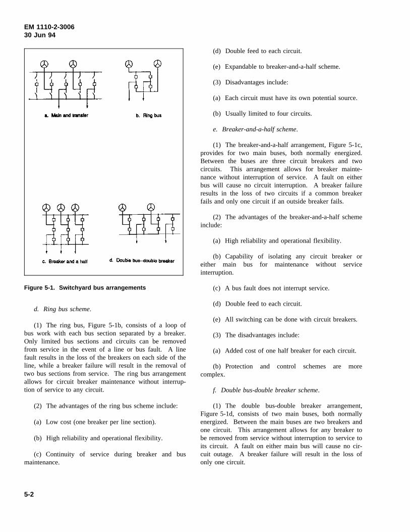
EM 1110-2-300630 Jun 94
Figure 5-1. Switchyard bus arrangements
d. Ring bus scheme.
(1) The ring bus, Figure 5-1b, consists of a loop ofbus work with each bus section separated by a breaker.Only limited bus sections and circuits can be removedfrom service in the event of a line or bus fault. A linefault results in the loss of the breakers on each side of theline, while a breaker failure will result in the removal oftwo bus sections from service. The ring bus arrangementallows for circuit breaker maintenance without interrup-tion of service to any circuit.
(2) The advantages of the ring bus scheme include:
(a) Low cost (one breaker per line section).
(b) High reliability and operational flexibility.
(c) Continuity of service during breaker and busmaintenance.
(d) Double feed to each circuit.
(e) Expandable to breaker-and-a-half scheme.
(3) Disadvantages include:
(a) Each circuit must have its own potential source.
(b) Usually limited to four circuits.
e. Breaker-and-a-half scheme.
(1) The breaker-and-a-half arrangement, Figure 5-1c,provides for two main buses, both normally energized.Between the buses are three circuit breakers and twocircuits. This arrangement allows for breaker mainte-nance without interruption of service. A fault on eitherbus will cause no circuit interruption. A breaker failureresults in the loss of two circuits if a common breakerfails and only one circuit if an outside breaker fails.
(2) The advantages of the breaker-and-a-half schemeinclude:
(a) High reliability and operational flexibility.
(b) Capability of isolating any circuit breaker oreither main bus for maintenance without serviceinterruption.
(c) A bus fault does not interrupt service.
(d) Double feed to each circuit.
(e) All switching can be done with circuit breakers.
(3) The disadvantages include:
(a) Added cost of one half breaker for each circuit.
(b) Protection and control schemes are morecomplex.
f. Double bus-double breaker scheme.
(1) The double bus-double breaker arrangement,Figure 5-1d, consists of two main buses, both normallyenergized. Between the main buses are two breakers andone circuit. This arrangement allows for any breaker tobe removed from service without interruption to service toits circuit. A fault on either main bus will cause no cir-cuit outage. A breaker failure will result in the loss ofonly one circuit.
5-2
EM 1110-2-300630 Jun 94
(2) The advantages of the double bus-double breakerscheme include:
(a) Very high reliability and operational flexibility.
(b) Any breaker or either bus can be isolated withoutservice interruption.
(c) A bus fault does not interrupt service.
(d) There is a double feed to each circuit.
(e) All switching is done with circuit breakers.
(f) Only one circuit is lost if a breaker fails.
(3) The disadvantages include the high cost of twobreakers per circuit.
g. Recommended scheme. The breaker-and-a-halfscheme is generally recommended, as it provides flexi-bility and a reasonably simple method of providing fullrelay protection under emergency switching conditions.The number of sections (line “bays”) needed is dependenton the number of transmission lines and generationsources coming into the substation. The breaker-and-a-half scheme is normally designed and operated as a ringbus until system requirements dictate more than sixbreakers and six lines.
5-4. Bus Structures
a. Arrangements. The flat or low profile type of busconstruction with pedestal-supported rigid buses and A-frame line towers is ordinarily the most economical wherespace and topography are favorable. Congested areasmay require the use of a high, narrow steel structure andthe use of short wire bus connections between disconnect-ing switches and the buses. Switchyard layouts shouldprovide adequate access for safe movement of mainte-nance equipment and the moving of future circuit breakersor other major items of equipment into position withoutde-energizing primary buses. Clearances to energizedparts should, as a minimum, comply with ANSI C2, Sec-tion 12. Equipment access requirements should be basedon the removal of high-voltage bushings, arresters, andconservators and radiators from large power transformers.
b. Bus design criteria. The design of rigid bus sys-tems is influenced by the following criteria:
(1) Electrical considerations including corona andampacity limitations.
(2) Structural considerations including ice and windloading, short-circuit forces, and seismic loads.
The spacing of bus supports should limit bus sag undermaximum loading to not greater than the diameter of thebus, or 1/150th of the span length. IEEE 605 providesfurther information on substation electrical, mechanical,and structural design considerations.
5-5. Switchyard Materials
a. General. After design drawings showing a gen-eral layout of the switchyard and details of electricalinterconnections have been prepared, a drawing should bemade up to accompany the specifications for the purchaseof the structures. This drawing should show the size,spacing, and location of principal members and the load-ings imposed by electrical equipment and lines. Designload assumptions for bus structures are described inEM 1110-2-3001.
b. Structure materials. The following are four typesof material most commonly used for substation structures:
(1) Steel. Steel is the most commonly used material.Its availability and good structural characteristics make iteconomically attractive. Steel, however, must have ade-quate corrosion protection such as galvanizing or painting.Due to the maintenance associated with painting, galva-nizing is generally preferred. Galvanized steel has anexcellent service record in environments where the pHlevel is in the range of 5.4 through 9.6 (i.e., a slightlyalkaline environment). Most industrial environments arein this pH range leading to the widespread use and excel-lent service record of galvanized steel structures. Becauseof the unbroken protective finish required, structuresshould not be designed to require field welding or drilling.Adequate information to locate mounting holes, brackets,and other devices must be provided to the fabricator toallow all detail work to be completed before the protec-tive finish is applied to the steel part.
(2) Aluminum. In environments where the pH levelis below 5.4 (i.e. an acidic environment, such as condi-tions existing in a brine mist), galvanized structures wouldgive poor service. In these environments, considerationshould be given to structures fabricated with aluminummembers. Aluminum structures are satisfactory at otherlocations, if the installed cost is comparable to the cost ofthe equivalent design using galvanized steel members.Structures designed for aluminum are constructed of Alloy6061-T6 and should be designed, fabricated, and erected
5-3
EM 1110-2-300630 Jun 94
in accordance with the Aluminum Association’s specifica-tions for aluminum structures.
(3) Concrete. Pre-cast, pre-stressed concrete struc-tures may be economical in some applications such aspull-off poles and switch structures. Care should be takento avoid the use of detrimental additives, such as calciumchloride, to the concrete used in the structures. Due tothe larger structural sizes and weights involved, specialequipment may be required for concrete erection.
(4) Wood. Wood pole and timber structures may beeconomical for temporary structures or simple switchstructures. Wood members must be treated with anappropriate preservative. Structural properties and sizetolerances of wood are variable and must be consideredduring the design process.
c. Bus materials. The materials most commonly usedfor rigid and wire bus are aluminum and copper. Rigidbus fittings should be limited to bolted connections forcopper, and welded connections on aluminum. Bus fit-tings for aluminum wire should be compression type.Either bolted or compression fittings are acceptable foruse with copper wire bus.
5-6. Transformer Leads
a. High-voltage terminal connections. The connec-tions between the high-voltage terminals of the trans-former and the disconnect switch (or breaker) will usuallybe made with bare overhead conductors when the trans-former is located in the switchyard. However, in caseswhere the transformer is in line with the axis of the dis-connect, the connection between the disconnect terminalsand the high-voltage bushing terminals can be made withsuitably supported and formed rigid bus of the same typeused in the rest of the switchyard. The fittings and inter-connection systems between the high-voltage bus and thedisconnect switches should be designed to accommodateconditions of frequent load cycling and minimalmaintenance.
b. Overhead conductors. Bare overhead conductorsfrom the transmission line termination to the high-voltagebushings can occasionally be used when the transformersare installed at the powerhouse, and overhead lines to theswitchyard are used. An example of this would be whenthe transmission line is dead-ended to the face of the dam,and the transformer is located at the base of the dam nearits face, and behind the powerhouse. However, locatingthe transformers at the powerhouse usually requires theuse of high-voltage bus to the line termination when the
line is terminated on a dead-end structure near thetransformer.
c. Test terminals. To provide a safe and accuratemethod of transformer dielectric testing, accommodationsshould be made for easily isolating transformer bushingsfrom the bus work. Double test terminals should be pro-vided on transformer high-voltage and neutral bushings inaccordance with Corps of Engineers practice. The designshould provide adequate clearance from energized linesfor personnel conducting the tests.
5-7. Powerhouse - Switchyard Power Control andSignal Leads
a. Cable tunnel.
(1) A tunnel for power and control cables should beprovided between the powerhouse and switchyard when-ever practical. Use of a tunnel provides ready access tothe cables, provides for easy maintenance and expansion,and offers the easiest access for inspection. This tunnelshould extend practically the full length of the switchyardfor access to all of the switchyard equipment.
(2) The control and data (non-signal) cables shouldbe carried in trays in the tunnel, and continued in steelconduits from the trays to circuit breakers and other con-trolled equipment so as to eliminate the need for man-holes and handholes. If there is a control house in theswitchyard, it should be situated over the tunnel. Thetunnel should be lighted and ventilated and provided withsuitable drains, or sumps and pumps.
(3) If the generator leads, transformer leads, or sta-tion service feeders are located in the tunnel, the amountof heat dissipated should be calculated and taken intoconsideration in providing tunnel ventilation. The powercables should be carefully segregated from the control anddata acquisition cables to prevent electromagnetic interfer-ence, and to protect the other cables from damage result-ing from power cable faults. If the tunnel lies below apossible high-water elevation, it should be designed towithstand uplift pressures.
(4) Signal cables should be physically separatedfrom power and control circuits. If practical, the signalcable should be placed in cable trays separate from thoseused for either control or power cables. In no case shouldsignal cables be run in conduit with either control orpower cables. The physical separation is intended toreduce the coupling of electromagnetic interference intothe signal cable from pulses in the (usually unshielded)
5-4
EM 1110-2-300630 Jun 94
control cables, or power system frequency energy frompower cables. Even though the signal cable will beshielded, commercially available shielding does not pro-vide 100 percent coverage or perfect shielding, and theseparation is needed to reduce electrical noise super-imposed on the signal.
b. Duct line. For small installations having a limitedamount of transforming and switching equipment, it maybe desirable and economical to use duct lines instead of acable tunnel for control and power cables. The ductsystem should use concrete encased nonmetallic conduit,and manholes or handholes of adequate number and sizeshould be provided. Separate ducts for the power cablesand the control and data acquisition cables should beprovided. At least 30 percent spare duct capacity shouldbe provided for power cables, and 50 percent spare capac-ity provided for control and data acquisition cables. Themanholes should be designed to drain unless costs areprohibitive.
c. High-voltage bus.
(1) General. There are three categories of high-volt-age connection systems that find application in hydroelec-tric installations requiring high-voltage interconnectionbetween the power plant and the switchyard or utility gridinterconnection. These are as follows:
(a) Oil or SF6 gas-insulated cable with paper-insulatedconductors. Cables commonly used for circuits above69 kV consist of paper-insulated conductors pulled into awelded steel pipeline, which is filled with insulating oil orinert gas. The oil or gas in the pipe type construction isusually kept under about 200 psi pressure. These cablescan safely be installed in the same tunnel between thepowerhouse and the switchyard that is used for controlcables.
(b) Solid dielectric-insulated cable. Solid dielectric-insulated cables are also available for systems above69 kV. Their use may be considered, but careful evalua-tion of their reliability and performance record should bemade. They offer advantages of ease of installation,elimination of oil or gas system maintenance, and lowercost. Their electrical characteristics should be consideredin fault studies and stability studies.
(c) SF6 gas-insulated bus. An example of a typicalinstallation is an underground power plant with a unitswitching scheme and the GSU transformer located under-ground in the plant. A high-voltage interconnection is
required through a cable shaft or tunnel to an above-ground on-site switchyard.
(2) Direct burial. While insulated cable of the typedescribed can be directly buried, the practice is not rec-ommended for hydroelectric plants because the incremen-tal cost of a tunnel normally provided for control circuitsand pipelines is moderate. In case of oil leaks or cablefailure, the accessibility of the cable pipes in the tunnelwill speed repairs and could avoid considerable loss inrevenue. Space for the location of cable terminal equip-ment should be carefully planned.
(3) Burial trench. If the power cables from thepowerhouse to the switchyard must be buried directly inthe earth, the burial trench must be in accordance withsafety requirements, provide a firm, conforming base tolay the cable on, and provide protection over the cable.The cable must have an overall shield, which must bewell-grounded, to protect, so far as possible, people whomight accidently penetrate the cable while digging in theburial area.
(4) SF6 gas-insulated systems. SF6 gas-insulatedsystems offer the possibility of insulated bus and completehigh-voltage switchyard systems in a compact space.Gas-insulated substation systems should be considered forunderground power plant installations or any situationrequiring a substation system in an extremely confinedspace. The design should accommodate the need fordisassembly of each part of the system for maintenance orrepair. The designer should also consider that the gas isinert, and in a confined space will displace oxygen andcause suffocation. After exposure to arcing, SF6 gascontains hazardous byproducts and special precautions areneeded for evacuating the gas and making the equipmentsafe for normal maintenance work. SF6 gas pressurevaries with temperature and will condense at low ambienttemperatures. When SF6 equipment is exposed to lowtemperatures, heating must be provided. The manufac-turer’s recommendations must be followed. IEEEC37.123 provides guidance on application criteria for gasinsulated substation systems.
5-8. Circuit Breakers
a. Interrupting capacity. The required interruptingrating of the circuit breakers is determined by short-circuitfault studies. (See Chapter 2.) In conducting the studies,conservative allowances should be made to accommodateultimate system growth. If information of system capac-ity and characteristics is lacking, an infinite bus at the end
5-5
EM 1110-2-300630 Jun 94
of the transmission interconnection can be assumed.Using an infinite bus will result in conservative values offault kVA to be interrupted, and will probably not undulyinfluence the final result. ANSI C37.06 provides perfor-mance parameters of standard high-voltage breakers.
b. Design considerations.
(1) Breakers for 69kV and above generally are SF6
gas-insulated, with the dead tank design preferred forseismic considerations. The details of the relaying willdetermine the number of CTs required, but two CTs perpole should generally be the minimum. Three CTs maybe required for the more complex switching arrangements,such as the breaker-and-a-half scheme.
(2) At 230 kV and above, two trip coils are preferred.The integrity of the tripping circuit(s) should be moni-tored and if remotely controlled, the status should betelemetered to the control point. The gas system of SF6
breakers should be monitored since loss of SF6 gas or lowgas pressure blocks breaker operation.
(3) Breaker auxiliary “a” and “b” switch contacts areused extensively to initiate and block the operation ofbackup relaying schemes. As breakers are added, andprotection added to cover new system contingencies, theprotective relay schemes become more complex. Toaccommodate these situations, breakers should be pur-chased with at least eight “a” and eight “b” spare auxil-iary contacts.
(4) Layout of the substation should consider accessrequired for maintenance equipment, as well as horizontaland vertical electrical clearance for the switches in allnormal operating positions.
(5) Specifications prepared for outdoor applications ofSF6 power circuit breakers should provide the expectedambient operating temperature ranges so the breaker man-ufacturer can provide adequate heating to ensure properoperation of the breaker through the ambient operatingrange. Minimum standard operating ambient for SF6
equipment is -30 °C (IEEE Standard C37.122).
5-9. Disconnect Switches
a. Disconnect operators. Manual or motor-operatedgang-operated disconnect switches should be provided forisolating all circuit breakers. For operating voltages of230 kV or greater, or for remotely operated disconnects,the disconnects should be motor operated. In some cases,depending on the switching scheme and substation layout,
one or both of the buses will be sectionalized by discon-nects. The sectionalizing disconnect switches may beeither manual or motor-operated, depending on their volt-age rating and the requirements of station design. Themanual operating mechanism for heavy, high-voltagedisconnects should preferably be of the worm gear, crank-operated type.
b. Remotely operated disconnects. Remotely oper-ated disconnect switches should be installed only as lineor breaker disconnects. Use of a remotely operated dis-connect switch to serve as generator disconnect is stronglydiscouraged. Operation of generator disconnects shouldrequire visual verification (through operator presence) ofthe open position and a lockable open position to preventthe possibility of misoperation or misindication by recon-necting an out-of-service generator to an energized line.
c. Disconnect features. All disconnect switchesshould be equipped with arcing horns. The disconnectswitch on the line side of the line circuit breakers shouldbe equipped with grounding blades and mechanicallyinterlocked operating gear. At 230kV and above, lineand generator disconnect switches should be of the rotat-ing insulator, vertical break type, with medium- or high-pressure contacts. Circuit breaker isolation switches maybe either a two-insulator “V” or a side break type. Boththe contacts and the blade hinge mechanism should bedesigned and tested to operate satisfactorily under severeice conditions. At 345kV and 500kV, vertical breakdisconnects are preferred since they allow for reducedphase spacing and installation of surge suppression resis-tors. Each switch pole should have a separate motoroperator.
5-10. Surge Arresters
a. Preferred arrester types. Surge arresters shouldbe of the station type (preferably a metal oxide type) thatprovides the greatest protective margins to generatingstation equipment.
b. Arrester location. Arresters should be locatedimmediately adjacent to the transformers, if the connec-tion between the transformers and switching equipment ismade by overhead lines. If high-voltage cable is used forthis connection, the arresters should be placed both nearthe switchyard terminals of the cable and adjacent to thetransformer terminals. Arrester connections should bedesigned to accommodate removal of the arrester withoutremoving the main bus connection to the high-voltagebushing. Location of arresters should be in accordancewith IEEE C62.2.
5-6
EM 1110-2-300630 Jun 94
c. Arrester protection. In all cases, enough spaceshould be allowed between arresters and other equipmentto prevent damage if the arresters should fail. If arrestersare located where they form a hazard to operating person-nel, they should be suitably enclosed. This can generallybe accomplished with a woven wire fence provided with alockable gate. The design of the enclosure should con-sider the clearance requirements for the switchyard operat-ing voltage.
d. Arrester voltage rating. The voltage rating of thearresters should be selected to provide a reasonable mar-gin between the breakdown voltage of the arrester and thebasic impulse insulation level (BIL) of the equipmentprotected. The rating, in the majority of cases, should bethe lowest satisfactory voltage for the system to which thearresters are connected.
e. Grounded-neutral arresters.
(1) In applying grounded-neutral rated arresters, thedesigner should consider whether, under all conditions ofoperation, the system characteristics will permit their use.Grounded-neutral arresters should not be used unless oneof the following conditions will exist:
(a) The system neutral will be connected to the sys-tem ground through a copper grounding conductor ofadequate size (solidly grounded) at every source of supplyof short-circuit current.
(b) The system neutral is solidly grounded or isgrounded through reactors at a sufficient number of thesources of supply of short-circuit current so the ratio ofthe fundamental-frequency zero-sequence reactance, Xo, tothe positive sequence reactance, X1, as viewed from thepoint of fault, lies between values of 0 and 3.0 for aground fault to any location in the system, and for anycondition of operation. The ratio of the zero-sequenceresistance, Ro, to the positive sequence reactance, X1, asviewed from the ground fault at any location, should beless than 1.0. The arrester should have suitable character-istics so that it will not discharge during voltage risescaused by switching surges or fault conditions.
(2) Consideration should be given to the protectionof transmission line equipment that may be locatedbetween the arresters and the incoming transmission lineentrance to the substation. In cases where the amount ofequipment is extensive or the distance is substantial, itwill probably be desirable to provide additional protectionon the incoming transmission line, such as spark gaps orarresters.
(3) If the station transformers are constructed withthe high-voltage neutral connection terminated on anexternal (H0) bushing, a surge arrester should be appliedto the bushing.
5-7
EM 1110-2-300630 Jun 94
Chapter 6Generator-Voltage System
6-1. General
The generator-voltage system described in this chapterincludes the leads and associated equipment between thegenerator terminals and the low-voltage terminals of theGSU transformers, and between the neutral leads of thegenerator and the power plant grounding system. Theequipment generally associated with the generator-voltagesystem includes switchgear; instrument transformers formetering, relaying, and generator excitation systems;neutral grounding equipment; and surge protection equip-ment. The equipment is classified as medium-voltageequipment.
6-2. Generator Leads
a. General. The term “generator leads” applies to thecircuits between the generator terminals and the low-voltage terminals of the GSU transformers. The equip-ment selected depends upon the distance between thegenerator and transformer, the capacity of the generator,the type of generator breakers employed, and the econom-ics of the installation. There are two general classes ofgenerator leads: those consisting of metal-enclosed busesand those consisting of medium-voltage cables. The twoclasses, their advantages, disadvantages, and selectioncriteria are discussed in the following subparagraphs.
b. Metal-enclosed buses. There are three categoriesof metal-enclosed bus: nonsegregated-phase, segregated-phase, and isolated-phase. Each type has specific applica-tions dependent mainly on current rating and type ofcircuit breaker employed with the bus.
(1) Nonsegregated-phase buses. All phase conductorsare enclosed in a common metal enclosure without barri-ers, with phase conductors insulated with molded materialand supported on molded material or porcelain insulators.This bus arrangement is normally used with metal-cladswitchgear and is available in ratings up to 4,000 A(6,000 A in 15-kV applications) in medium-voltageswitchgear applications.
(2) Segregated-phase buses. All phase conductors areenclosed in a common enclosure, but are segregated bymetal barriers between phases. Conductor supports usu-ally are of porcelain. This bus arrangement is available inthe same voltage and current ratings as nonsegregated-phase bus, but finds application where space limitations
prevent the use of isolated-phase bus or where highermomentary current ratings than those provided by thenonsegregated phase are required.
(3) Isolated-phase buses. Each phase conductor isenclosed by an individual metal housing, which is sepa-rated from adjacent conductor housings by an air space.Conductor supports are usually of porcelain. Bus systemsare available in both continuous and noncontinuous hous-ing design. Continuous designs provide an electricallycontinuous housing, thereby controlling external magneticflux. Noncontinuous designs provide external magneticflux control by insulating adjacent sections, providinggrounding at one point only for each section of the bus,and by providing shorting bands on external supportingsteel structures. Noncontinuous designs can be consideredif installation of the bus will be at a location where com-petent field welders are not available. However, continu-ous housing bus is recommended because of the difficultyin maintaining insulation integrity of the noncontinuoushousing design during its service life. Isolated-phase busis available in ratings through 24,000 A and is associatedwith installations using station cubicle switchgear (seediscussion in paragraph 6-7b).
c. Metal-enclosed bus application criteria.
(1) For most main unit applications, the metal-enclosed form of generator leads is usually preferred, withpreference for the isolated-phase type for ratings above3,000 A. Enclosed buses that pass through walls or floorsshould be arranged so as to permit the removal of hous-ings to inspect or replace insulators.
(2) On isolated-phase bus runs (termed “delta bus”)from the generators to a bank of single-phase GSU trans-formers, layouts should be arranged to use the mosteconomical combination of bus ratings and lengths ofsingle-phase bus runs. The runs (“risers”) to the single-phase transformers should be sized to carry the currentcorresponding to the maximumkVA rating of thetransformer.
(3) Metal-enclosed bus connections to the GSUtransformer that must be supported at the point of connec-tion to the transformer should have accommodations per-mitting the bus to be easily disconnected should thetransformer be removed from service. The bus designshould incorporate weather-tight closures at the point ofdisconnection to prevent moisture from entering the inte-rior of the bus housing.
6-1
EM 1110-2-300630 Jun 94
(4) On all enclosed bus runs, requirements forenclosing the connections between the bus and the low-voltage bushings of the GSU transformer should be coor-dinated and responsibilities for scopes of supply clearlydefined between transformer supplier and bus supplier.Details of the proposed design of the connector betweenthe GSU transformer bushing terminals and the bus termi-nal should be evaluated to ensure probability of reliableservice life of the connection system.
d. Insulated cables.
(1) Cables may be appropriate for some small genera-tors or in installations where the GSU transformer islocated in the plant’s switchyard. In the latter situation,economic and technical evaluations should be made todetermine the most practical and cost-effective method tomake the interconnection. Cables, if used, should havecopper conductors. Acceptable cable types include:
(a) Single conductor, ethylene-propylene-rubber(EPR) insulated, with non-PVC jacket.
(b) Multi-conductor, ethylene-propylene-rubber (EPR)insulated cables, with aluminum or steel sheath, and non-PVC jacket, in multiple if necessary to obtain capacity.
(c) Oil-pipe cable systems.
(2) Oil-filled cable terminations with cables termi-nated with a conductor lug and a stress cone should beused for terminating oil-pipe cable systems. Cold shrinktermination kits should be used for terminating single andmulti-conductor EPR cables. Termination devices andkits should meet the requirements of IEEE 48 for Class Iterminations.
(3) When cables of any type are run in a tunnel, theeffect of cable losses should be investigated to determinethe safe current-carrying capacity of the cable and theextent of tunnel ventilation required to dissipate the heatgenerated by these losses. Locations where hot spots mayoccur, such as risers from the tunnel to equipment orconduit exposed to the sun, should be given fullconsideration.
6-3. Neutral Grounding Equipment
Equipment between the generator neutral and groundshould, insofar as practicable, be procured along with thegenerator main leads and switchgear. The conductor maybe either metal-enclosed bus or insulated cable in non-magnetic conduit. Generator characteristics and system
requirements determine whether the machine is to besolidly grounded through a circuit breaker (usually notpossible), through a circuit breaker and reactor (or resis-tor), or through a disconnecting switch and a distributiontype of transformer (See Chapter 3.) Solidly groundedsystems do not find wide application because resultingfault currents initiated by a stator to ground fault aremuch higher than currents produced by alternative neutralgrounding systems. Higher ground fault currents lead tohigher probability of damage to the stator laminations ofthe connected generator. If a circuit breaker is used inthe grounding scheme, it can be either a single-pole or astandard 3-pole air circuit breaker with poles paralleled toform a single-pole unit. Suitable metal enclosures shouldbe provided for the reactors, resistors, or grounding trans-formers used in the grounding system.
6-4. Instrument Transformers
a. General. The instrument transformers requiredfor the unit control and protective relaying are included inprocurements for metal-clad switchgear breakers that areto be employed for generator switching. The instrumenttransformers are mounted in the switchgear line-up withpotential transformers mounted in draw-out compartmentsfor maintenance and service. Current transformers for theGSU transformer zone differential relay are also mountedin the metal-clad switchgear cubicles. In isolated-phasebus installations, the instrument transformers are includedin procurement for the isolated-phase bus. The currenttransformers, including those for generator differential andtransformer differential protection, are mounted “in-line”in the bus with terminations in external terminal compart-ments. Required potential transformers are mounted indedicated compartments tapped off the main bus leads.The dedicated compartments also contain the generatorsurge protection equipment (see Chapter 3, “Generators”).Specified accuracy classes for instrument transformers foreither type of procurement should be coordinated with therequirements of the control, protective relaying, andmetering systems. Instrument transformers for the genera-tor excitation system should be included in the appropriateprocurement.
b. Current transformers. Current transformers of themultiple secondary type are usually required and aremounted in the isolated-phase bus or in the metal-cladswitchgear to obtain the necessary secondary circuitswithin a reasonable space. Current transformers in theneutral end of the generator windings are usually mountedin the generator air housing. Accessibility for short-circuiting the secondary circuits should be considered inthe equipment layout. The current transformers should be
6-2
EM 1110-2-300630 Jun 94
designed to withstand the momentary currents and short-circuit stresses for which the bus or switchgear is rated.
c. Potential transformers. The potential transformersfor metering and for excitation system service are housedin separate compartments of the metal-clad switchgear. Ifstation cubicle breakers or isolated-phase bus areinvolved, a special cubicle for potential transformers andsurge protection equipment is provided in a variety ofarrangements to simplify generator lead connections.Potential transformers should be protected by current-limiting resistors and fuses. Draw-out type mountings arestandard equipment in metal-clad switchgear. Similararrangements are provided in cubicles associated withisolated-phase bus. Cubicles with the isolated-phase busesalso provide phase isolation for transformers.
6-5. Single Unit and Small Power PlantConsiderations
When metal-clad switchgear is used for generators insmall plants (having typically one or two generators ofapproximately 40,000kW or less) the switchgear may beequipped with indicating instruments, control switches,and other unit control equipment (e.g., annunciators andrecorders) mounted on the switchgear cell doors. Thisarrangement can take the place of a large portion of theconventional control switchboard. The switchgear may belocated in a control room, or the control room omittedentirely, depending upon the layout of the plant. Currentphilosophy is to make the smaller plants suitable forunmanned operation, and remote or automatic control.This scheme eliminates the need for a control room.Arrangements for control equipment with this type ofscheme are described in more detail in Chapter 8,“Control System.”
6-6. Excitation System Power PotentialTransformer
The power potential transformer (PPT) is fed from thegenerator leads as described in paragraph 3-6e(2), Chap-ter 3, “Generators.” The PPT is procured as part of theexcitation system equipment. The PPT should be a three-phase, 60-Hz, self-cooled, ventilated dry type transformer.The PPT is generally tapped at the generator bus withprimary current limiting fuses, designed for floor mount-ing, and with a low-voltage terminal chamber with provi-sions for terminating the bus or cable from the excitationsystem power conversion equipment.
6-7. Circuit Breakers
a. General. The particular switching schemeselected from those described in Chapter 2, “BasicSwitching Provisions,” the generator voltage and capacityrating, and results from fault studies will determine thetype of generator breaker used for switching, togetherwith its continuous current rating and short-circuit currentrating. If a “unit” switching scheme is chosen withswitching on the high side of the GSU transformer, thencriteria regarding high-voltage power circuit breakers asdescribed in Chapter 5, “High-Voltage System” are usedto select an appropriate breaker. If a generator-voltageswitching scheme is selected, then criteria outlined in thisparagraph should be used for breaker selection.
b. Generator-voltage circuit breaker types.
(1) When generator-voltage circuit breakers arerequired, they are furnished in factory-built steel enclo-sures in one of three types. Each type of circuit breakerhas specific applications dependent on current ratings andshort-circuit current ratings. In general, Table 6-1 pro-vides a broad overview of each breaker type and its rangeof application for generator switching. The three typesare as follows:
(a) Metal-clad switchgear. Metal-clad switchgearbreakers can be used for generator switching on units ofup to 45MVA at 13.8kV, depending on interrupting dutyrequirements. Details of construction are covered inGuide Specification for Civil Works Construction CWGS-16345. Either vacuum interrupters or SF6 interruptingmediums are permitted by the guide specification.
(b) Station-type cubicle switchgear. Station-typebreakers can be used in generator switching applicationson units of approximately 140MVA. Details of construc-tion are covered in IEEE C37.20.2. For SF6 circuitbreakers, the insulating and arc-extinguishing medium isthe gas. For indoor equipment, in areas not allowed toreach temperatures at or near freezing, the gas will proba-bly not require heating provisions. However, special careand handling is needed for SF6 gas.
(c) In-line isolated-phase bus breakers. For high-current, medium-voltage, generator breaker applications,i.e., 15kV, 6,000 Amp or higher, in-line breakersmounted in the isolated-phase bus system have beenemployed on high-capacity systems. These breakers
6-3
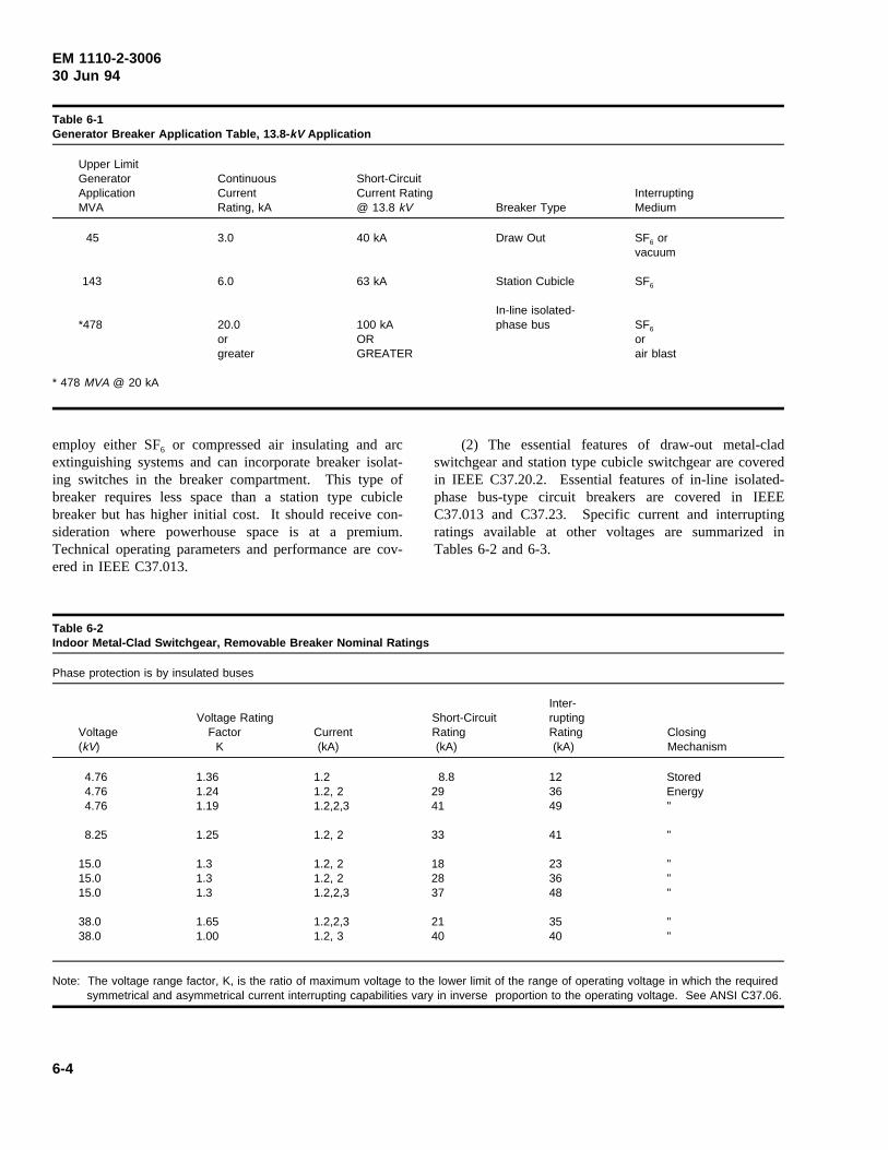
EM 1110-2-300630 Jun 94
Table 6-1Generator Breaker Application Table, 13.8- kV Application
Upper LimitGenerator Continuous Short-CircuitApplication Current Current Rating InterruptingMVA Rating, kA @ 13.8 kV Breaker Type Medium
45
143
*478
3.0
6.0
20.0orgreater
40 kA
63 kA
100 kAORGREATER
Draw Out
Station Cubicle
In-line isolated-phase bus
SF6 orvacuum
SF6
SF6
orair blast
* 478 MVA @ 20 kA
employ either SF6 or compressed air insulating and arcextinguishing systems and can incorporate breaker isolat-ing switches in the breaker compartment. This type ofbreaker requires less space than a station type cubiclebreaker but has higher initial cost. It should receive con-sideration where powerhouse space is at a premium.Technical operating parameters and performance are cov-ered in IEEE C37.013.
(2) The essential features of draw-out metal-cladswitchgear and station type cubicle switchgear are coveredin IEEE C37.20.2. Essential features of in-line isolated-phase bus-type circuit breakers are covered in IEEEC37.013 and C37.23. Specific current and interruptingratings available at other voltages are summarized inTables 6-2 and 6-3.
Table 6-2Indoor Metal-Clad Switchgear, Removable Breaker Nominal Ratings
Phase protection is by insulated buses
Inter-Voltage Rating Short-Circuit rupting
Voltage Factor Current Rating Rating Closing(kV) K (kA) (kA) (kA) Mechanism
4.764.764.76
8.25
15.015.015.0
38.038.0
1.361.241.19
1.25
1.31.31.3
1.651.00
1.21.2, 21.2,2,3
1.2, 2
1.2, 21.2, 21.2,2,3
1.2,2,31.2, 3
8.82941
33
182837
2140
123649
41
233648
3540
StoredEnergy"
"
"""
""
Note: The voltage range factor, K, is the ratio of maximum voltage to the lower limit of the range of operating voltage in which the requiredsymmetrical and asymmetrical current interrupting capabilities vary in inverse proportion to the operating voltage. See ANSI C37.06.
6-4
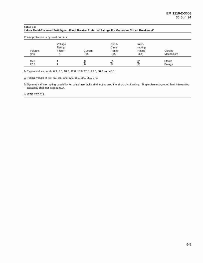
EM 1110-2-300630 Jun 94
Table 6-3Indoor Metal-Enclosed Switchgear, Fixed Breaker Preferred Ratings For Generator Circuit Breakers 4 /
Phase protection is by steel barriers
Voltage Short- Inter-Rating Circuit rupting
Voltage Factor Current Rating Rating Closing(kV) K (kA) (kA) (kA) Mechanism
15.827.5
11
1/1/
2/2/
3/3/
StoredEnergy
1/ Typical values, in kA: 6.3, 8.0, 10.0, 12.0, 16.0, 20.0, 25.0, 30.0 and 40.0.
2/ Typical values in kA: 63, 80, 100, 120, 160, 200, 250, 275.
3/ Symmetrical interrupting capability for polyphase faults shall not exceed the short-circuit rating. Single-phase-to-ground fault interruptingcapability shall not exceed 50A.
4/ IEEE C37.013.
6-5
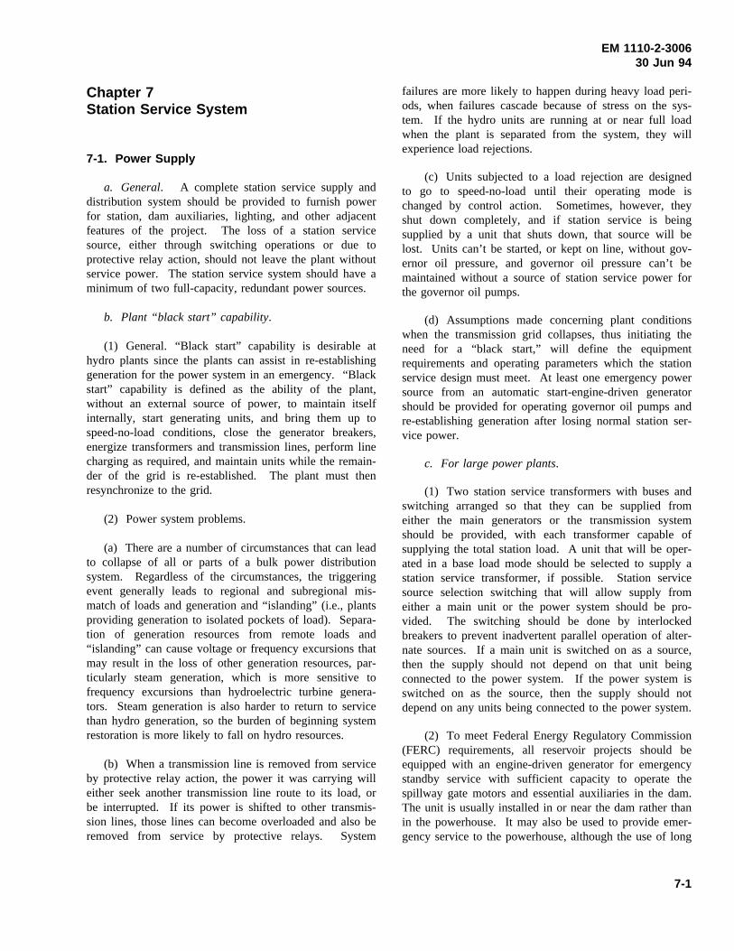
EM 1110-2-300630 Jun 94
Chapter 7Station Service System
7-1. Power Supply
a. General. A complete station service supply anddistribution system should be provided to furnish powerfor station, dam auxiliaries, lighting, and other adjacentfeatures of the project. The loss of a station servicesource, either through switching operations or due toprotective relay action, should not leave the plant withoutservice power. The station service system should have aminimum of two full-capacity, redundant power sources.
b. Plant “black start” capability.
(1) General. “Black start” capability is desirable athydro plants since the plants can assist in re-establishinggeneration for the power system in an emergency. “Blackstart” capability is defined as the ability of the plant,without an external source of power, to maintain itselfinternally, start generating units, and bring them up tospeed-no-load conditions, close the generator breakers,energize transformers and transmission lines, perform linecharging as required, and maintain units while the remain-der of the grid is re-established. The plant must thenresynchronize to the grid.
(2) Power system problems.
(a) There are a number of circumstances that can leadto collapse of all or parts of a bulk power distributionsystem. Regardless of the circumstances, the triggeringevent generally leads to regional and subregional mis-match of loads and generation and “islanding” (i.e., plantsproviding generation to isolated pockets of load). Separa-tion of generation resources from remote loads and“islanding” can cause voltage or frequency excursions thatmay result in the loss of other generation resources, par-ticularly steam generation, which is more sensitive tofrequency excursions than hydroelectric turbine genera-tors. Steam generation is also harder to return to servicethan hydro generation, so the burden of beginning systemrestoration is more likely to fall on hydro resources.
(b) When a transmission line is removed from serviceby protective relay action, the power it was carrying willeither seek another transmission line route to its load, orbe interrupted. If its power is shifted to other transmis-sion lines, those lines can become overloaded and also beremoved from service by protective relays. System
failures are more likely to happen during heavy load peri-ods, when failures cascade because of stress on the sys-tem. If the hydro units are running at or near full loadwhen the plant is separated from the system, they willexperience load rejections.
(c) Units subjected to a load rejection are designedto go to speed-no-load until their operating mode ischanged by control action. Sometimes, however, theyshut down completely, and if station service is beingsupplied by a unit that shuts down, that source will belost. Units can’t be started, or kept on line, without gov-ernor oil pressure, and governor oil pressure can’t bemaintained without a source of station service power forthe governor oil pumps.
(d) Assumptions made concerning plant conditionswhen the transmission grid collapses, thus initiating theneed for a “black start,” will define the equipmentrequirements and operating parameters which the stationservice design must meet. At least one emergency powersource from an automatic start-engine-driven generatorshould be provided for operating governor oil pumps andre-establishing generation after losing normal station ser-vice power.
c. For large power plants.
(1) Two station service transformers with buses andswitching arranged so that they can be supplied fromeither the main generators or the transmission systemshould be provided, with each transformer capable ofsupplying the total station load. A unit that will be oper-ated in a base load mode should be selected to supply astation service transformer, if possible. Station servicesource selection switching that will allow supply fromeither a main unit or the power system should be pro-vided. The switching should be done by interlockedbreakers to prevent inadvertent parallel operation of alter-nate sources. If a main unit is switched on as a source,then the supply should not depend on that unit beingconnected to the power system. If the power system isswitched on as the source, then the supply should notdepend on any units being connected to the power system.
(2) To meet Federal Energy Regulatory Commission(FERC) requirements, all reservoir projects should beequipped with an engine-driven generator for emergencystandby service with sufficient capacity to operate thespillway gate motors and essential auxiliaries in the dam.The unit is usually installed in or near the dam rather thanin the powerhouse. It may also be used to provide emer-gency service to the powerhouse, although the use of long
7-1
EM 1110-2-300630 Jun 94
supply cables from the dam to the powerhouse could be adisadvantage.
(3) For a large power plant, a second automatic startemergency power source may be required in the power-house. Besides diesel engine-generators, small combus-tion turbines are an option, although they are morecomplex and expensive than diesel engine-generator sets.
(4) Any emergency source should have automaticstart control. The source should be started wheneverstation service power is lost. The emergency sourcecontrol should also provide for manual start from theplant control point. It is also important to provide localcontrol at the emergency source for non-emergency startsto test and exercise the emergency source. A load shed-ding scheme may be required for any emergency source,if the source capacity is limited.
d. For small, one-unit power plants. One stationservice transformer supplied from the transmission systemshould be provided for a normal station service bus, andan emergency station service bus should be supplied froman engine-driven generator. The emergency source shouldhave sufficient capacity to operate the spillway gatemotors and minimum essential auxiliaries in the dam andpowerhouse such as unwatering pumps, governor oilpumps, and any essential preferred AC loads.
e. Station service distribution system.
(1) In many plants, feeders to the load centers can bedesigned for 480-V operation. In a large plant, wherelarge loads or long feeder lengths are involved, use of13.8-kV or 4.16-kV distribution circuits will be satisfactorywhen economically justified. Duplicate feeders (onefeeder from each station service supply bus) should beprovided to important load centers. Appropriate controlsand interlocking should be incorporated in the design toensure that critical load sources are not supplied from thesame bus. Feeder interlock arrangements, and sourcetransfer, should be made at the feeder source and not atthe distribution centers.
(2) The distribution system control should be thor-oughly evaluated to ensure that all foreseeable contingen-cies are covered. The load centers should be located ataccessible points for convenience of plant operation andaccessibility for servicing equipment. Allowance shouldbe made for the possibility of additional future loads.
(3) All of the auxiliary equipment for a main unit isusually fed from a motor control center reserved for that
unit. Feeders should be sized based on maximumexpected load, with proper allowance made for voltagedrop, motor starting inrush, and to withstand short-circuitcurrents. Feeders that terminate in exposed locationssubject to lightning should be equipped with surge arrest-ers outside of the building.
(4) Three-phase, 480-V station service systems usingan ungrounded-delta phase arrangement have the lowestfirst cost. Such systems will tolerate, and allow detectionof, single accidental grounds without interrupting serviceto loads. Three-phase, grounded-wye arrangements findwidespread use in the industrial sector and with someregulatory authorities because of perceived benefits ofsafety, reliability, and lower maintenance costs over a480-V delta system. Industrial plants also have a higherpercentage of lighting loads in the total plant load. Instal-lation costs for providing service to large concentrationsof high-intensity lighting systems are lower with480/277-V wye systems. Delta systems are still preferredin hydro stations because of the cleaner environment,good service record, and skilled electricians available tomaintain the system.
f. Station service switchgear.
(1) Metal-clad switchgear with SF6 or vacuum circuitbreakers should be supplied for station service systemvoltage above 4.16kV. Metal-enclosed switchgear with600-V drawout air circuit breakers should be used on480-V station service systems. The switchgear should belocated near the station service transformers.
(2) The station service switchgear should have asectionalized bus, with one section for each normal stationservice source. Switching to connect emergency sourcepower to one of the buses, or selectively, to either busshould be provided. If the emergency source is onlyconnected to one bus, then the reliability of the stationservice source is compromised since the bus suppliedfrom the emergency source could be out of service whenan emergency occurred. It is preferable that the emer-gency source be capable of supplying either bus, with thebreakers interlocked to prevent parallel operation of thebuses from the emergency source.
(3) Each supply and bus tie breaker should be elec-trically operated for remote operation from the controlroom in attended stations. As a minimum, bus voltageindication for each bus section should be provided at theremote point where remote plant operation is provided.Transfer between the two normal sources should be auto-matic. Transfer to the emergency power sources should
7-2
EM 1110-2-300630 Jun 94
also be automatic when both normal power sources fail.Feeder switching is performed manually except for spe-cific applications.
(4) In large station service systems with a double busarrangement, source/bus tie breakers should be located ateach end of the switchgear compartment. The source/bustie breakers should not be located in adjacent compart-ments because a catastrophic failure of one breaker coulddestroy or damage adjacent breakers leading to completeloss of station service to the plant. In large plants wherethere is sufficient space, it is even safer to provide aseparate, parallel cubicle lineup for each station servicebus for more complete physical isolation. Even with thisarrangement, feeder and tie breakers should not be locatedin adjacent compartments.
(5) For 480-V station service systems, a delta-connected, ungrounded system is recommended for thefollowing reasons:
(a) Nature of the loads. The load in a hydroelectricpower plant is made up predominantly of motor loads. Ina commercial or light industrial facility, where the load ispredominantly lighting, the installation of a 480/277 V,wye-connected system is more economical due to the useof higher voltages and smaller conductor sizes. Theseeconomies are not realized when the load is predomi-nantly motor loads. For high bay lighting systems, certaininstallation economies may be realized through the use of480/277-V wye-connected subsystems, as described inChapter 12.
(b) Physical circuit layout. Wye-connected systemsallow the ability to quickly identify and locate a faultedcircuit in a widely dispersed area. Although hydroelectricpower plants are widely dispersed, the 480-V system isconcentrated in specific geographic locales within theplant, allowing rapid location of a faulted circuit, aided bythe ground detection system described in paragraph 7-2.
7-2. Relays
An overlapping protected zone should be provided aroundcircuit breakers. The protective system should operate toremove the minimum possible amount of equipment fromservice. Overcurrent relays on the supply and bus tiebreakers should be set so feeder breakers will trip on afeeder fault without tripping the source breakers. Groundovercurrent relays should be provided for wye-connectedstation service systems. Ground detection by a voltagerelay connected in the broken delta corner of three poten-tial transformers should be provided for ungrounded or
delta-connected systems (ANSI C37.96). Bus differentialrelays should be provided for station service systems of4.16 kV and higher voltage. The adjustable trippingdevice built into the feeder breaker is usually adequate forfeeder protection on station service systems using 480-Vlow-voltage switchgear.
7-3. Control and Metering Equipment
Indicating instruments and control should be provided onthe station service switchgear for local control. A voltme-ter, an ammeter, a wattmeter, and a watthour meter areusually sufficient. A station service annunciator should beprovided on the switchgear for a large station servicesystem. Contact-making devices should be provided withthe watthour meters for remote indication of station ser-vice energy use. Additional auxiliary cabinets may berequired for mounting breaker control, position indication,protective relays, and indicating instruments. For largeplants, physical separation of control and relay cubiclesshould be considered so control and relaying equipmentwill not be damaged or rendered inoperable by the cata-strophic failure of a breaker housed in the same or adja-cent cubicle.
7-4. Load/Distribution Centers
Protective and control devices for station auxiliary equip-ment should be grouped and mounted in distributioncenters or, preferably, motor control centers. The motorstarters, circuit beakers, control switches, transferswitches, etc., should all be located in motor controlcenters.
7-5. Estimated Station Service Load
a. General.
(1) The maximum demand that is expected on thestation service system is the basis for developing stationservice transformer ratings. The expected demand may bedetermined from a total of the feeder loads with an appro-priate diversity factor, or by listing all connected loadsand corresponding demand loads inkVA. A diversityfactor smaller than 0.75 should not be used. During highactivity periods or plant emergencies, higher than normalstation service loads can be expected and if a small diver-sity factor has been used, the system may not have ade-quate capacity to handle its loads.
(2) Demand factors used for developing stationservice equipment capacities can vary widely due to thetype of plant (high head stand-alone power plant versus
7-3
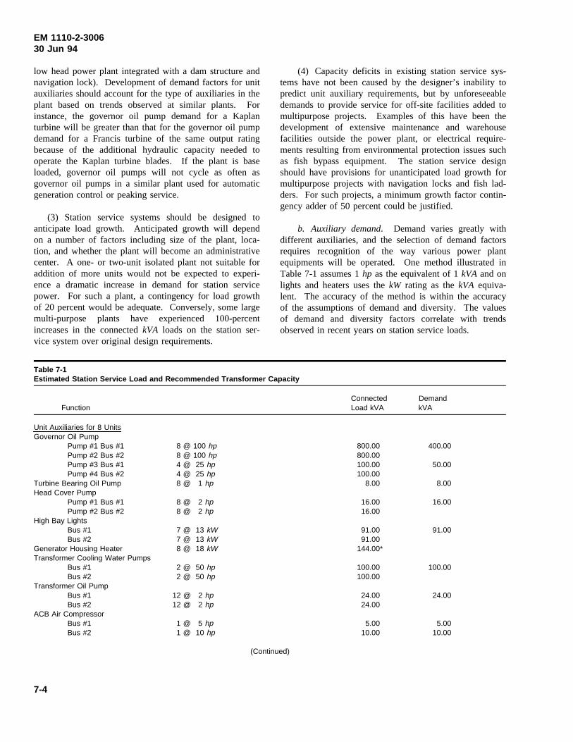
EM 1110-2-300630 Jun 94
low head power plant integrated with a dam structure andnavigation lock). Development of demand factors for unitauxiliaries should account for the type of auxiliaries in theplant based on trends observed at similar plants. Forinstance, the governor oil pump demand for a Kaplanturbine will be greater than that for the governor oil pumpdemand for a Francis turbine of the same output ratingbecause of the additional hydraulic capacity needed tooperate the Kaplan turbine blades. If the plant is baseloaded, governor oil pumps will not cycle as often asgovernor oil pumps in a similar plant used for automaticgeneration control or peaking service.
(3) Station service systems should be designed toanticipate load growth. Anticipated growth will dependon a number of factors including size of the plant, loca-tion, and whether the plant will become an administrativecenter. A one- or two-unit isolated plant not suitable foraddition of more units would not be expected to experi-ence a dramatic increase in demand for station servicepower. For such a plant, a contingency for load growthof 20 percent would be adequate. Conversely, some largemulti-purpose plants have experienced 100-percentincreases in the connectedkVA loads on the station ser-vice system over original design requirements.
(4) Capacity deficits in existing station service sys-tems have not been caused by the designer’s inability topredict unit auxiliary requirements, but by unforeseeabledemands to provide service for off-site facilities added tomultipurpose projects. Examples of this have been thedevelopment of extensive maintenance and warehousefacilities outside the power plant, or electrical require-ments resulting from environmental protection issues suchas fish bypass equipment. The station service designshould have provisions for unanticipated load growth formultipurpose projects with navigation locks and fish lad-ders. For such projects, a minimum growth factor contin-gency adder of 50 percent could be justified.
b. Auxiliary demand. Demand varies greatly withdifferent auxiliaries, and the selection of demand factorsrequires recognition of the way various power plantequipments will be operated. One method illustrated inTable 7-1 assumes 1hp as the equivalent of 1kVA and onlights and heaters uses thekW rating as thekVA equiva-lent. The accuracy of the method is within the accuracyof the assumptions of demand and diversity. The valuesof demand and diversity factors correlate with trendsobserved in recent years on station service loads.
Table 7-1Estimated Station Service Load and Recommended Transformer Capacity
Connected DemandFunction Load kVA kVA
Unit Auxiliaries for 8 UnitsGovernor Oil Pump
Pump #1 Bus #1 8 @ 100 hp 800.00 400.00Pump #2 Bus #2 8 @ 100 hp 800.00Pump #3 Bus #1 4 @ 25 hp 100.00 50.00Pump #4 Bus #2 4 @ 25 hp 100.00
Turbine Bearing Oil Pump 8 @ 1 hp 8.00 8.00Head Cover Pump
Pump #1 Bus #1 8 @ 2 hp 16.00 16.00Pump #2 Bus #2 8 @ 2 hp 16.00
High Bay LightsBus #1 7 @ 13 kW 91.00 91.00Bus #2 7 @ 13 kW 91.00
Generator Housing Heater 8 @ 18 kW 144.00*Transformer Cooling Water Pumps
Bus #1 2 @ 50 hp 100.00 100.00Bus #2 2 @ 50 hp 100.00
Transformer Oil PumpBus #1 12 @ 2 hp 24.00 24.00Bus #2 12 @ 2 hp 24.00
ACB Air CompressorBus #1 1 @ 5 hp 5.00 5.00Bus #2 1 @ 10 hp 10.00 10.00
(Continued)
7-4
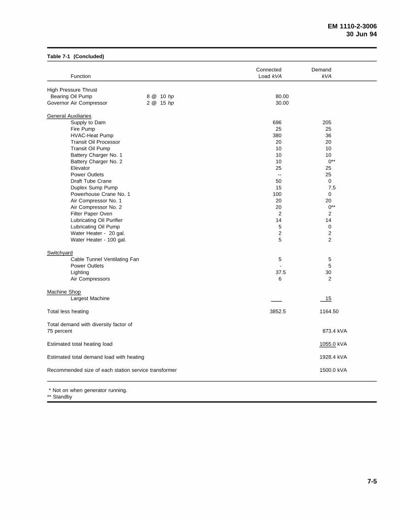
EM 1110-2-300630 Jun 94
Table 7-1 (Concluded)
Connected DemandFunction Load kVA kVA
High Pressure ThrustBearing Oil Pump 8 @ 10 hp 80.00
Governor Air Compressor 2 @ 15 hp 30.00
General AuxiliariesSupply to Dam 696 205Fire Pump 25 25HVAC-Heat Pump 380 36Transit Oil Processor 20 20Transit Oil Pump 10 10Battery Charger No. 1 10 10Battery Charger No. 2 10 0**Elevator 25 25Power Outlets -- 25Draft Tube Crane 50 0Duplex Sump Pump 15 7.5Powerhouse Crane No. 1 100 0Air Compressor No. 1 20 20Air Compressor No. 2 20 0**Filter Paper Oven 2 2Lubricating Oil Purifier 14 14Lubricating Oil Pump 5 0Water Heater - 20 gal. 2 2Water Heater - 100 gal. 5 2
SwitchyardCable Tunnel Ventilating Fan 5 5Power Outlets - 5Lighting 37.5 30Air Compressors 6 2
Machine ShopLargest Machine 15
Total less heating 3852.5 1164.50
Total demand with diversity factor of75 percent 873.4 kVA
Estimated total heating load 1055.0 kVA
Estimated total demand load with heating 1928.4 kVA
Recommended size of each station service transformer 1500.0 kVA
* Not on when generator running.** Standby
7-5
EM 1110-2-300630 Jun 94
Chapter 8Control System
8-1. General
a. Scope. The control system as discussed in thischapter deals with equipment for the control and protec-tion of apparatus used for power generation, conversion,and transmission. It does not include low-voltage panel-boards and industrial control equipment as used with plantauxiliaries. IEEE 1010 and EPRI EL-5036, Volume 10,provide guidelines for planning and designing controlsystems for hydroelectric power plants.
b. Control system components. The control systemconsists primarily of a computer-based control system,hard-wired logic or programmable logic, indicating andrecording instruments, control switches, protective relays,and similar equipment. The greatest part of this equip-ment should be grouped at one location to facilitatesupervision and operation of the main generating units,transmission lines, and station auxiliaries. The groupingof these controls at one location within the confines of thepower plant is termed “centralized control.”
c. Start-stop sequence. Each generator unit controlsystem should be provided with a turbine/generator start-stop sequencing logic using a master relay located at thegenerator (or unit) switchboard. The starting sequencebegins with pre-start checks of the unit, followed by start-ing unit auxiliaries, and ends with the unit operating underthe speed-no-load condition. Manual or automatic syn-chronizing and closure of the unit breaker can be per-formed at the local control location. The stoppingsequence should provide for four types of unit shutdown:protective relaying, operator’s emergency stop switch,mechanical problems, and normal shutdown.
d. Generator switchboards. Generator switchboardsin larger power plants are located near the controlledgenerator. The switchboards provide local control of theunit. In smaller power plants, where metal-clad switch-gear is used for switching the generator, unit controlequipment is located on auxiliary panels of the switchgearline-up. Like the switchboards, the auxiliary panel equip-ment provides local control of the unit.
e. Auxiliary equipment control. Large power plantsusing high-voltage busing and switching or having anadjacent switchyard as part of the development shouldhave control for this equipment located in the groupingsuggested in paragraph 8-1(b). Even though the
controlled equipment is remote from the plant, the equip-ment is not “offsite.” Offsite control denotes control froma location not resident to the plant, i.e., another plant or acontrol complex at another location.
f. Control room location. In plants with a few units,the control room location with its centralized controlsshould provide ready access to the governor control cabi-nets. In plants with ultimately four or more units, thecontrol room should be located near the center of theultimate plant or at a location allowing ready access to theunits and adjacent switchyard. The relative number andlengths of control circuits to the units and to the switch-yard is a factor to consider, but is secondary to consider-ation of operating convenience. The control room shouldbe an elevation above maximum high water, if there isany danger that the plant may be flooded. A decision onthe location of the control room should be reached at anearly stage of plant design, since many other features ofthe plant are affected by the control room location. Con-trol location definitions and control modes are furtherdescribed in IEEE 1010.
g. Smaller plants. In smaller power plants, whereindoor generator-voltage busing and switching are used,hinged instrument panels on the switchgear cubiclesshould be used as mounting space for main control equip-ment. This results in the main group of control equip-ment being located at the main switchgear location.
8-2. Control Equipment
a. General. Centralized automatic and manual con-trol equipment should be located in the control room oflarge power plants. The control console, in conjunctionwith supervisory control and data acquisition (SCADA)equipment and the status switchboard, enables the controlroom operator to control the powerhouse operation.Equipment racks housing automatic synchronizing andcentralized auxiliary equipment should be located in oradjacent to the control room to facilitate connections withcontrol room equipment. If the plant is controlled fromoffsite, the plant’s SCADA equipment should be locatedin or adjacent to the control room.
b. Space allocation. Space allotted for controlequipment, whether in a separate control room or in themain switchgear cubicle area, must be large enough toaccommodate the panels required for the ultimate numberof generating units and transmission lines. The spacerequirement, as well as the size and location of openingsrequired in the floor, should be provided to the architec-tural and structural designers to ensure proper consider-ation in door, room, and floor slab designs.
8-1
EM 1110-2-300630 Jun 94
c. Cabinet construction. Generator switchboard pan-els and doors should be 1/8-in. thick or No. 11 U.S.S.gauge smooth select steel with angle or channel edgesbent to approximately a 1/4-in. radius. Panels should bemounted on sills ready for powerhouse installation ingroups as large as can be shipped and moved into theinstallation area. All equipment on the switchboardsshould be mounted and wired at the factory, and theboards should be shipped to the powerhouse with allequipment in place.
d. Equipment arrangement. The arrangement ofequipment on the control switchgear, switchboard, orcontrol console should be carefully planned to achievesimplicity of design and to replicate unit control place-ments familiar to the intended operating staff. Simplicityof design is a definite aid to operation and tends to reduceoperating errors; therefore, the relative position of devicesshould be logical and uniform. Switchboard and controlconsole design should be patterned after an appropriateexample to attain a degree of standardization in thearrangement of indicating instruments and basic controlswitches. Control switches should be equipped withdistinctive handles as shown in Table 8-1. Each item ofequipment should be located by consideration of its func-tions, its relation to other items of equipment, and by itsuse by the operator.
8-3. Turbine Governor
The digital governor electrical control cabinet usually islocated adjacent to the generator switchboard separatefrom the actuator cabinet. The control cabinet containsgovernor electronic or digital “proportional-integral-derivative” (P-I-D) control components. The actuatorcabinet housing the power hydraulics of the governorsystem is located to minimize the pressure line runsbetween the turbine servomotors, the actuator, and thegovernor pressure tank. For smaller capacity governorsand smaller plants, governor electronic and hydrauliccontrols are all located in the governor actuator cabinet.For mechanical considerations of turbine governors, seeEM 1110-2-4205.
8-4. Large Power Plant Control
a. General. Centralized control system equipment islocated in the control room and is interconnected to thegenerator switchboards located near the units. Requiredcontrol and monitoring of all functions of the hydroelec-tric power project are provided to the operators. Thecontrol console with conventional control devices and
monitoring equipment in conjunction with a computer-based data acquisition and control system (DACS), pro-vides control and indication access to individual items ofequipment to facilitate operation, supervision, and control.Hard-wired pushbutton switches provide for direct opera-tor manual control of unit start-stop, breaker close (initiat-ing automatic synchronizing), breaker trip, voltage,loading, and gate limit raise-lower. Analog or digitalpanel meters and indicating lights continuously indicatethe status of all main units, breakers, transformers, andlines. The DACS system display monitors and keyboardsare available to operator control. The unit controls andinstruments supplement or duplicate those on the genera-tor switchboard, and provide the control room operatorwith the ability to transfer control of any selected unit orgroup of units to the generator switchboard in case ofsystem trouble. The control console may also providespillway gate control, fishway control, project communi-cations, and other project equipment control functionswhen required.
b. Equipment location. Arrangement of control andinstrument switches and mimic bus should simulate therelative order of interconnections or physical order of theplant arrangement assisting the operator in forming amental picture of connections. The top of the controlconsole panel should be inclined to provide easier accessto the control switches and to improve console visibility.Layouts of console visual display terminals (VDTs)should follow applicable guidelines contained in Chap-ter 12, “Lighting and Receptacle Systems,” to ensure goodvisual acuity of the displays. Panels of the control con-sole should be arranged for ultimate development, so thatthe addition of a control panel for another generator oranother line will not disturb existing equipment.
c. Status switchboard. The status switchboard con-tains graphic and visual indication, generator load record-ers, station total megawatts and megavars recorders, andother required project data displays. The status switch-board should be located for easy observation from thecontrol console. The status switchboard should be astandard modular vertical rack enclosure joined togetherto form a freestanding, enclosed structure.
d. Equipment racks. Equipment racks should beprovided for mounting line relays, automatic synchroniz-ing equipment, the common and outside annunciatorchassis, auxiliary relays, communication equipment, andtransfer trip equipment. The equipment racks should bestandard, modular, vertical rack enclosures.
8-2
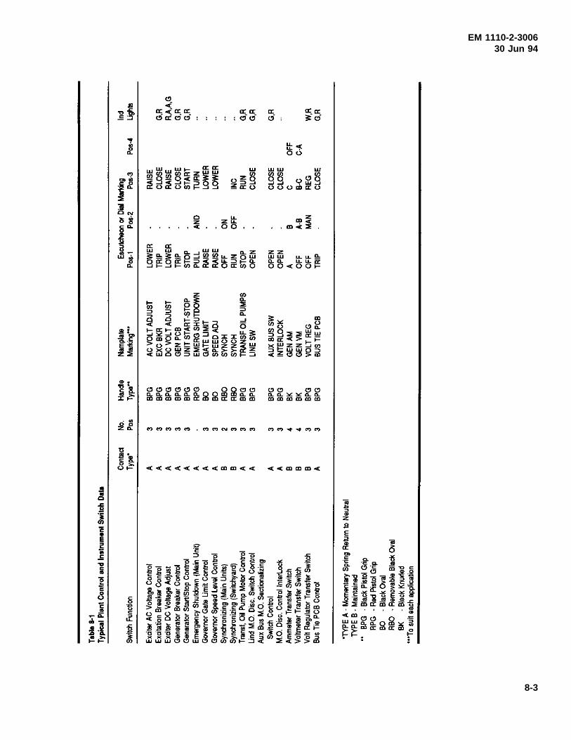
EM 1110-2-300630 Jun 94
8-3
EM 1110-2-300630 Jun 94
e. SCADA equipment. The SCADA and communi-cation equipment should be located in the general controlarea.
8-5. Small Power Plant Control
a. General. Small power plants using medium-volt-age metal-clad switchgear for generator control imposedifferent limitations on equipment arrangements thanarrangement limitations of generator switchboards forlocal unit control. This is due to the variety of equipmentavailable with switchgear and, consequently, the differentpossibilities for locations for major control equipment.As noted in paragraph 8-1g, hinged instrument panels onthe main switchgear can be used for control equipment.Where space and switchgear construction allow, it isdesirable to have hinged instrument panels on the side ofthe stationary structure opposite the doors for removingthe breakers. These panels, however, provide space foronly part of the necessary control equipment, and one ormore auxiliary switchgear compartments will be requiredto accommodate the remaining equipment.
b. Equipment location. Annunciator window panels,indicating instruments, control switches, and similarequipment should be mounted on the switchgear hingedpanels. The hinged panel for each breaker section shouldbe assigned to the generating unit, transmission line, orstation service transformer that the breaker serves andonly the indicating instruments, control switches, etc.,associated with the controlled equipment mounted on thepanel. A hinged synchronizing panel should be attachedto the end switchgear cubicle.
c. Additional equipment location. Protective relays,temperature indicators, load control equipment, and otherequipment needed at the control location and not providedfor on the switchgear panels should be mounted on theauxiliary switchgear compartments.
d. SCADA equipment. Small power plants are fre-quently unattended and remotely controlled from an off-site location using SCADA equipment. The SCADA andcommunication equipment should be located in the gen-eral control area.
8-6. Protective Relays
a. General. The following discussion on protectiverelays includes those devices which detect electrical faultsor abnormal operating conditions and trip circuit breakersto isolate equipment in trouble or notify the operatorthrough alarm devices that corrective action is required.
The application of relays must be coordinated with thepartitioning of the electrical system by circuit breakers, sothe least amount of equipment is removed from operationfollowing a fault, preserving the integrity of the balanceof the plant’s electrical system.
(1) Generally, the power transmitting agency protec-tion engineer will coordinate with the Corps of Engineersprotection engineer to recommend the functional require-ments of the overlapping zones of protection for the maintransformers and high voltage bus and lines. The Corpsof Engineers protection engineer will determine the pro-tection required for the station service generators andtransformers, main unit generators, main transformers, andpowerhouse bus.
(2) Electromechanical protective relays, individualsolid state protective relays, multi-function protectiverelays, or some combination of these may be approved asappropriate for the requirements. Traditional electro-mechanical protective relays offer long life but may mal-function when required to operate, while many lesspopular designs are no longer manufactured. Individualsolid state protective relays and/or multi-function protec-tive relays offer a single solution for many applicationsplus continuous self diagnostics to alarm when unable tofunction as required. Multi-function protective relays maybe cost-competitive for generator and line protection whenmany individual relays would be required. When multi-function relays are selected, limited additional backuprelays should be considered based upon safety, the cost ofequipment lost or damaged, repairs, and the energy lostduring the outage or repairs if appropriate.
(3) When the protection engineer determines thatredundancy is required, a backup protective relay with adifferent design and algorithm should be provided forreliability and security. Fully redundant protection israrely justified even with multi-function relay applications.Generators, main transformers, and the high voltage busare normally protected with independent differentialrelays.
(4) When the protective relays have been approved,the protection engineer will provide or approve the set-tings required for the application.
b. Main generators.
(1) The general principles of relaying practices forthe generator and its excitation system are discussed inIEEE standards C37.101, C37.102, and C37.106.
8-4
EM 1110-2-300630 Jun 94
Unless otherwise stated, recommendations contained inthe above guides apply to either attended or unattendedstations.
(2) Differential relays of the high speed, percentagedifferential type are usually provided to protect the statorwindings of generators rated above 1500kVA.
(3) A high-impedance ground using a resistance-loaded distribution transformer scheme is generally used,thereby limiting generator primary ground fault current toless than 25 A. A generator ground, AC overvoltagerelay with a third harmonic filter is connected across thegrounding impedance to sense zero-sequence voltage. Ifthe generator is sharing a GSU transformer with anotherunit, a timed sequential ground relay operation to isolateand locate generator and delta bus grounds should beprovided.
(4) Out-of-step relays are usually provided to protectgenerators connected to a 500-kV power system, becausethe complexity of a modern EHV power system some-times leads to severe system frequency swings, whichcause generators to go out of step. The generator out-of-step relays should incorporate an offset mho and angleimpedance relay system which can detect an out-of-stepcondition when the swing locus passes through the gener-ator or its transformer.
(5) Frequency relays, and under- and over-frequencyprotection, are not required for hydraulic-turbine-drivengenerators.
(6) Temperature relays are provided for thrust andguide bearings as backup for resistance temperature detec-tors and indicating thermometers with alarms. The relaysare set to operate at about 105o C and are connected toshut down the unit. Shutdown at 105o C will not save thebabbitt on the bearing but will prevent further damage tothe machine.
c. Generator breakers.
(1) Most breaker failure relaying schemes operate onhigh phase or ground currents. When a trip signal isapplied to the breaker, the breaker should open and cur-rent flow should cease within the breaker interruptingtime. The breaker failure relay is usually applied to oper-ate lockout relays to trip backup breakers after a timedelay based on the assumption the breaker has failed ifcurrent flow continues after the breaker trip circuit hasbeen energized. These schemes do not provide adequate
protection if breaker failure occurs while current is nearzero immediately following synchronizing.
(2) Another scheme uses a breaker auxiliary contactto detect breaker failure with fault detectors for phasecurrent balance, reverse power, and overcurrent relays.Protective relay contact closing or operation of thebreaker control switch to the trip position energizes atiming relay. If the breaker auxiliary contact does notclose within the breaker interrupting time, the timing relaywill close its contacts, enabling the phase current balance,reverse power, and overcurrent relays to perform therequired trip functions.
(3) Some breaker control systems monitor thebreaker trip coil using a high resistance coil relay con-nected in series with the trip coil. A time delay relay isrequired to allow the breaker to open during normal trip-ping without initiating an alarm.
(4) Provision should be made to trip generator brea-kers when there is a loss of the breaker trip circuit DCcontrol power or complete loss of DC for the entire plant.A stored energy capacitor trip device can be used to tripthe breaker in case of a loss of control power.
d. Transformer protection.
(1) Transformers or transformer banks over1500kVA should be protected with high-speed percent-age-type differential relays. The basic principles involvedin transformer protection are discussed in IEEE C37.91.
(2) Separate differential relay protection for genera-tors and transformers should be provided even on unitinstallations without a generator circuit breaker. Therelays applicable for generators can be set for much closercurrent balance than transformer differential relays.
(3) Auto transformers can be treated as three-winding transformers and protected with suitable high-speed differential relays. The tertiary winding of anauto-transformer usually has a much lowerkVA ratingthan the other windings. The current transformer ratiosshould be based on voltage ratios of the respective wind-ings and all windings considered to have the same(highest)kVA rating.
(4) Thermal relays supplement resistance tempera-ture detectors and thermometers with alarm contacts. Therelays are set to operate when the transformer temperaturereaches a point too high for safe operation, and are
8-5
EM 1110-2-300630 Jun 94
connected to trip breakers unloading the transformers.These relays are important for forced-oil water-cooledtransformers which may not have any capacity ratingwithout cooling water.
e. Bus protection.
(1) High-voltage switchyard buses can be protectedwith bus protection, but the necessity and type of busprotection depends on factors including bus configuration,relay input sources, and importance of the switchyard inthe transmission system. Application of bus protectionshould be coordinated with the PMA or utility operatingagency. The basic principles of bus protection operationare discussed in IEEE C37.97.
(2) Large power plants with a complex station servicesystem configuration should be provided with stationservice switchgear bus differential relay protection.
(3) A ground relay should be provided on the delta-connected buses of the station service switchgear. Avoltage relay, connected to the broken-delta potentialtransformer secondary windings, is usually provided todetect grounds. A loading resistor may be placed acrossthe broken delta to prevent possible ferroresonance. Theground detector usually provides only an alarm indication.
f. Feeder protection. Feeder circuits that operate atmain generator voltage and 4160-V station service feedersshould be protected with overcurrent relays having instan-taneous trip units and a ground relay. The setting of theground relay should be coordinated with the setting of thegenerator ground relay to prevent shutdown of a generatordue to a grounded feeder.
g. Transmission line protection. Relays for the pro-tection of transmission lines should be selected on thebasis of dependability of operation, selectivity required forcoordination with existing relays on the interconnected
system, speed of operation required to maintain systemstability, coordinating characteristics with relays on theother end of the line, and the PMA or utility system oper-ating requirements. The basic principles of relaying prac-tices are discussed in IEEE C37.95.
h. Shutdown relays. The shutdown lockout relaysstop the unit by operating shutdown equipment and trip-ping circuit breakers. The lockout relay operations areusually divided into two groups. A generator electricallockout relay, 86GX, is initiated by protective relaying orthe operator’s emergency trip switch. The generatormechanical lockout relay, 86GM, is triggered bymechanical troubles, such as bearing high temperatures orlow oil pressure. The unit shutdown sequence isdescribed in IEEE 1010.
8-7. Automatic Generation Control (AGC)
For computer-based control systems, unit load can becontrolled in accordance with an error signal developedby digital computers periodically sampling real powerflow over the tie line, line frequency, and generator poweroutput. These analog signals are continuously monitoredat the load dispatch control center to obtain the plantgeneration control error. The control error digital quantityis transmitted via telemetry to each plant and allocated tothe units by the computer-based plant control system.AGC action by the plant control system converts theraise/lower megawatt signal into a timed relay contactclosure to the governor. The governor produces a wicketgate open/close movement to change the generator outputpower. Other modes of operation include set point con-trol, regulating, base loaded, ramped control, manualcontrol, and others relative to the nature of the project andoperating philosophy. Coordination of the engineeringplanning of the AGC with the marketing agency shouldbegin at an early stage.
8-6
EM 1110-2-300630 Jun 94
Chapter 9Annunciation Systems
9-1. General
EPRI EL-5036, Volume 10, provides guidelines andconsiderations in planning and designing annunciationsystems for power plants.
9-2. Audio and Visual Signals
Every power plant should be provided with an annuncia-tion system providing both audible and visual signals inthe event of trouble or abnormal conditions.
a. Audio signals. Howler horns and intermittentgongs are used for audible signal devices. An intermittentgong is provided in the plant control room. Howler hornsare used in the unit area and in areas where the back-ground noise is high (e.g., in the turbine pit) or in areasremote from the unit (e.g., plant switchyard).
b. Visual signals. Visual signals are provided bylighted lettered window panels of the annunciator. Inlarger plants, the annunciator panel indication isaugmented by unit trouble lamps located in a readilyvisible position close to the unit. The plant sequence ofevents recorder (SER) is normally located in the controlroom. Separate annunciators (when provided) for stationservice systems and switchyards should be located onassociated control panels of the station service switchgearor on the switchyard control panels.
9-3. Annunciator
a. General. The annunciator system should bedesigned for operation on the ungrounded 125-V DC sys-tem discussed in Chapter 11. All remote contacts usedfor trouble annunciation should be electrically independentof contacts used for other purposes so annunciator circuitsare separated from other DC circuits. Auxiliary relaysshould be provided where electrically independent con-tacts cannot otherwise be obtained. The annunciatorequipment should use solid-state logic units, lighted-window or LED type, designed and tested for surge with-standing capability in accordance with ANSI C37.90.1,and manufactured in accordance with ANSI/ISA S18.1.
b. The switchboard annunciator operational sequenceshould be a manual or automatic reset sequence as listedin Table 9-1.
Automatic reset should be employed when there is eitheran SER or a SCADA system backup. When the plant iscontrolled and dispatched through the SCADA system ofthe wheeling utility, the design reset features of theannunciator should be coordinated to ensure properoperation.
c. The generator switchboard is provided withannunciator alarm points for unit emergency shutdown,generator differential lockout, generator incomplete start,generator or 15-kV bus ground, generator overspeed,generator overcurrent, generator breaker low pressure, unitcontrol power loss, generator CO2 power off, PT fusefailure or undervoltage, and head cover high water.
Table 9-1Switchboard Annunciator Operational Sequence
AuxiliaryField Control Alarm or RepeaterContact Pushbutton or Switch Lights Horn Contacts
Normal -- Off Off Off
Abnormal Flashing On On
Abnormal Acknowledge or Silence On Off On
Normal Reset Off Off Off
Normal Test On Off Off
9-1
EM 1110-2-300630 Jun 94
Certain alarm points have several trouble contacts inparallel by equipment group. Examples include generatorexcitation system trip or trouble, turbine bearing oiltrouble, generator cooling water flow, unit bearing over-heat, generator oil level, generator stator high temperature,and governor oil trouble.
d. The generator switchboard may be provided withan additional annunciator for the generator step-up trans-former and unit auxiliary equipment alarms, depending onthe plant arrangement. Generally, these alarm points aretransformer differential, transformer lockout trip, trans-former overheat, transformer trouble, 480-V switchgeartrip, and trouble.
e. The generator excitation cubicle is provided withan annunciator for excitation equipment alarm points forAC regulator trip, bridge overtemperature, transformerover temperature, regulator power supply, field overvolt-age, maximum excitation limit, minimum excitation limit,and volt per Hertz. Generator overvoltage, power systemstabilizer, and fan failure alarm points should be includedwhen required.
f. The switchboard annunciator for large power plantsshould be provided with auxiliary or repeater contacts todrive control room console remote annunciator word-indicating lights.
g. A control console window-indicating light annun-ciator is common to all units. One unit at a time can beselected by use of the appropriate unit trouble statuslighted pushbutton. Visual indication is provided whenthe unit switchboard annunciator is activated. The con-sole window indicating lights are generally grouped byswitchboard annunciator points and provide essentialtrouble status to the operator. Unit troubles are normallycategorized by shutdown, differential, overcurrent, coolingwater, bearing oil, unit trouble, breaker air, CO2 dis-charge, control power, and head cover high water. The
window indicating light annunciator provides backup for asequential event recorder. Unit switchboard annunciatorremote control switches to silence and reset the switch-board annunciator should be provided on the controlconsole.
9-4. Sequence of Events Recorder (SER)
An SER should be provided to complement the plantannunciation system if a SCADA system is not perform-ing the sequence of events function. The SER provides atime-tagged, sequenced, printed record of trouble events.The documented record of a trouble event aids in diagnos-ing power plant forced outages. It is designed for opera-tion on an ungrounded 125-V DC system. All inputsshould be optically isolated and filtered for 125-V DC drycontact change-of-state scanning. The SER minimumresolution should be coordinated with using agencies. Avalue of 2 msec is typical. When an input signal statuschange occurs, the SER should automatically initiate andproduce a tabulated printed record on the data loggeridentifying the event and showing the time of statuschange (to the nearest millisecond). The SER should beprovided with a system clock and time synchronizationfeatures. Each SER system should be provided with anadequate input point capacity to monitor each alarm trou-ble contact and provide plant breaker status necessary forthe plant operation. The alarm trouble contacts shouldinclude IEEE 1010 requirements and project alarm pointsrequirements.
9-5. Trouble Annunciator Points
All of the alarm points listed in Table 9-2 below are notrequired in every plant, and, conversely, requirements foran unlisted alarm point may arise. IEEE 1010 providestypes of alarm signals transmitted to the generator annun-ciator from the generator, excitation system, generatorterminal cabinet, generator breaker, step-up transformer,turbine, and governor, which are listed in Table 9-2.
Table 9-2Alarm Signals Transmitted to the Generator Annunciator
Generator Switchboard Annunciator Points
Signal Description
86GX & 86GT Unit Emergency Shutdown87GX Generator Differential Shutdown48TDC Generator Incomplete Start64X Generator or 15-kV Bus Ground12G Generator Overspeed51GAR Generator Overcurrent63 Generator Breaker Low Pressure
(Continued)
9-2
EM 1110-2-300630 Jun 94
Table 9-2. (Continued)
Generator Switchboard Annunciator Points
Signal Description
74CB Control Power Loss63X CO2 Discharge27CO2 CO2 Power Off27G PT Fuse Fail or Undervoltage71HC Head Cover High Water* Generator Regulator Trip or Trouble* Turbine Bearing Oil Trouble* Generator Cooling Water Flow* Unit Bearing Oil Trouble* Generator Oil Level* Generator Stator High Temperature* Governor Oil Trouble
* See IEEE 1010
Step-Up Transformer Annunciation Points
Signal Description
87TAR Transformer Differential86L Transformer Lockout Trip (Includes Transformer Ground)74TL Transformer Control Power Loss* Transformer Overheat* Transformer Trouble20TDX Transformer Deluge
* See IEEE 1010
Line Annunciation Points
Signal Description
94L1 Line Lockout74 Line Relay or MW Power Off74 Microwave Trouble
Station Service Transformer Annunciation Points
Signal Description
86T Transformer Lockout63G,49,26Q,71Q Transformer Trouble94 Transformer Breaker Tripped63X CO2 Discharge
Station Annunciation Points
Signal Description
86BD Station Service Switchgear Bus DifferentialBA Station Service Switchgear DC Trouble
Station Annunciation Points
Signal Description
63 Station Service Switchgear Breaker Low Pressure94 Station Service Feeder Breaker Tripped
(Continued)
9-3
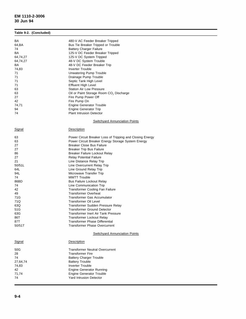
EM 1110-2-300630 Jun 94
Table 9-2. (Concluded)
BA 480-V AC Feeder Breaker Tripped64,BA Bus Tie Breaker Tripped or Trouble74 Battery Charger FailureBA 125-V DC Feeder Breaker Tripped64,74,27 125-V DC System Tripped64,74,27 48-V DC System TroubleBA 48-V DC Feeder Breaker Trip74,83 Inverter Trouble71 Unwatering Pump Trouble71 Drainage Pump Trouble71 Septic Tank High Level71 Effluent High Level63 Station Air Low Pressure63 Oil or Paint Storage Room CO2 Discharge27 Fire Pump Power Off42 Fire Pump On74,71 Engine Generator Trouble94 Engine Generator Trip74 Plant Intrusion Detector
Switchyard Annunciation Points
Signal Description
63 Power Circuit Breaker Loss of Tripping and Closing Energy63 Power Circuit Breaker Energy Storage System Energy27 Breaker Close Bus Failure27 Breaker Trip Bus Failure86 Breaker Failure Lockout Relay27 Relay Potential Failure21 Line Distance Relay Trip50/51L Line Overcurrent Relay Trip64L Line Ground Relay Trip94L Microwave Transfer Trip74 MWTT Trouble86BD Bus Failure Lockout Relay74 Line Communication Trip42 Transformer Cooling Fan Failure49 Transformer Overheat71G Transformer Gas Accumulator71Q Transformer Oil Level63Q Transformer Sudden Pressure Relay51G Transformer Ground Detector63G Transformer Inert Air Tank Pressure86T Transformer Lockout Relay87T Transformer Phase Differential50/51T Transformer Phase Overcurrent
Switchyard Annunciation Points
Signal Description
50G Transformer Neutral Overcurrent28 Transformer Fire74 Battery Charger Trouble27,64,74 Battery Trouble74,83 Inverter Trouble42 Engine Generator Running71,74 Engine Generator Trouble74 Yard Intrusion Detector
9-4
EM 1110-2-300630 Jun 94
Chapter 10Communication System
10-1. General
a. Types of systems available. Reliable communica-tion systems are vital to the operation of every powerplant. Voice communication is a necessity at all plantsand code-call signaling is generally required for accessingpersonnel at large power plants. Additional dedicatedcommunication systems are required for telemetering,SCADA, and for certain types of protective relaying.Communications media available for power plant applica-tion include: metallic cable pairs; leased telephone lines;power line carrier (PLC); radio frequency communica-tions, including two-way land mobile (TWLM) radio andterrestrial microwave (MW); fiber optics; and satellitecommunications.
b. Regulatory requirements. The Federal InformationResource Management Regulation (FIRMR), as adminis-tered by the General Services Administration (GSA),requires GSA approval for all communication systems(other than military) used by agencies of the FederalGovernment. The GSA contract with common carriersguarantees carriers access to Government long-distancecommunication business. The service to provide long-distance communications is known as FTS 2000. TheGSA requires its use by Government agencies, unless theagencies are able to prove, on a case-by-case basis, thatthe FTS 2000 service will not meet its needs. For infor-mation on the FIRMR, and approval documentationneeded, contact the Corps of Engineers Information Man-agement Office.
10-2. Voice Communication System
a. Telephone service. Normally, general internal andexternal telephone communications are provided throughpublic switched telephone network services installed andoperated by the serving telephone company. The equip-ment (including telephones) is leased from the telephonecompany. The communication circuits provided by acommercial telephone operating company include connec-tion to local exchange, long distance, WATS, and FTS2000 telephone service. Telephone pay stations in visitorareas should be provided for public convenience.
b. Plant equipment. The distributing frame andswitching equipment for any commercial systems shouldbe installed in a location near the control room where itcan be included in the air conditioning zone for the
control room. A preferred AC circuit should be providedfor the commercial equipment.
c. Telephone locations. To ensure adequate tele-phone access, sufficient telephone outlets should be pro-vided in the office area, the control room, the generatorfloor at each unit, the switchgear area, the station servicearea, and the plant’s repair shops. A telephone outletshould be provided in each elevator cab. Circuits totelephone outlets are provided by metallic cable pairs.Telephone wiring inside the plant, from the telephonecompany switching equipment location to the location ofthe various instruments, is provided by the Governmentand included in the powerhouse design. Embedded con-duits dedicated to telephone use are provided for thecables.
10-3. Dedicated Communications System
a. General. Dedicated communications systems areprovided in the plant for code call systems, SCADA sys-tems, protective relay systems, and for voice communica-tions to the dispatching centers and substations of thepower wheeling entity (either Federal Power MarketingAgency (PMA) or non-Federal utility). Communicationsmedia for performing these functions can be either leasedcommercial circuits, power line carrier (PLC), radio fre-quency communications, fiber-optic cable, satellite com-munications, or a combination of these media.
b. Code call system. Generally, code-call facilitiesare provided at all plants permitting paging of key person-nel. A separate, Government-owned code-call systemshould be provided when leased telephones are used, somaintenance of the code call will not depend on outsidepersonnel. An automatic repeating type code-sendingstation should be located on the control room operator’sdesk or console.
c. Utility telephone systems.
(1) Voice communications facilities for power plantcontrol and dispatch use are typically provided through autility or Federal PMA-owned telephone system. If it is aFederally owned system, the FIRMR requires the use ofFTS2000 for inter-local access and transport area service,unless an exception is granted. In some instances, themajor use of the communication channel has been thedetermining factor in whether Government ownership ofthe system is permitted. If the major use of the service istechnical; that is, plant operating and control information,then Government ownership has been approved.
10-1
EM 1110-2-300630 Jun 94
(2) The telephone system should provide access todispatching voice channels of the utility. Generally, dialautomatic telephone switching facilities provide a system-wide network of voice circuits which are automaticallyswitched to permit calling between generating stations,major substations, and control centers. Some plants haveused leased private line service for communications cir-cuits which are provided by a commercial telephone com-pany’s common carrier for the sole use of the plant.These circuits are provided on the cable and other trans-mission facilities of the carrier, but should not be con-nected directly to the network switching systems of thecarrier or telephone operating company.
d. Leased circuits.
(1) Leased commercial circuits can be used for voicecommunication circuits as described in paragraph 10-3c.Voice grade communication channels are required and aresupplied either through a dial or a dedicated system, withdedicated channels being the preferred alternative. Thebasic voice-bandwidth private line channel is an AT&Tsystem “Type 3002 unconditioned” channel. Other com-mercially available private line data channel services areDigital Data Service (DDS) and Basic Data Service(BDS). These latter services offer digital interconnectiv-ity through a wide range of data transmission speeds.
(2) Leased circuits have been used for plant protec-tive relaying circuits with mixed results. Generally, it isbetter to own the communication facility if it is used forvital high-speed relaying service. Some of the past prob-lems with leased channels have been loss of servicebecause of unannounced maintenance activity by theleasing agency, failure of the system, rerouting of theservice because of maintenance or construction activity,and accidental circuit interruption by personnel lookingfor trouble on other circuits. Typically, a leasingagency’s operating and maintenance personnel do notunderstand the level of reliability necessary for relayingcircuits.
(3) Leased circuits have been used for SCADA sys-tem control of plants and substations. Here, too, theresults have been mixed. For short distances where theleasing agency can provide a direct link between the localand remote station, results have been good. Where thecircuit has been routed through a central office, the reli-ability of service has in a number of cases not been of thelevel of reliability needed for data acquisition and control.The lack of reliability is apt to be more of a problem ifthe plant is in a remote location and served by a smalltelephone company. Use of leased facilities has to be
considered on a case-by-case basis, and all of the influ-encing factors need to be considered, including the servicerecord of the proposed leasing agency.
e. Power line carrier.
(1) A “basic” PLC system consists of three distinctparts:
(a) The terminal assemblies, consisting of the trans-mitters, receivers, and associated components.
(b) The coupling and tuning equipment, which pro-vides a means of connecting the PLCs terminals to thehigh-voltage transmission line.
(c) The high-voltage transmission line, which pro-vides the path for transmission of the carrier energy.High-voltage coupling capacitors are used to couple thecarrier energy to the transmission line, and simultaneouslyblock 60-Hz power from the carrier equipment.
(2) Most transmitter/receiver equipment is installedin standard 19-in. radio racks inside cabinets located nearthe plant control room. Carrier frequency energy is con-ducted out of the plant by coaxial cable to the high-volt-age transmission line tuning and coupling equipment.PLC equipment power requirements are supplied fromeither 48-V or 125-V DC derived from the station batteryor a dedicated communications battery source. If a PLCsystem is to be provided, routing provisions for the wireand cables needed must be included in the plant design.
(3) Power line carrier communication systems havefound extensive use for relaying, control, and voice com-munications in Europe, and in some areas of the UnitedStates. Their use is less popular in the United States,apparently because of the availability of radio frequencyspectrum, and utility-owned communication systems apartfrom the power transmission facilities. PLC bandwidth islimited because of its operating frequencies and the trans-mission medium. Its transmission path is susceptible tonoise from arcing faults, interruption by ground faults andother accidents to the line, and weather. If other reliablecommunication means are available at a reasonable cost,it would probably be advantageous to avoid the use ofPLC.
f. TWLM radio.
(1) There is some very limited use of TWLM radioin SCADA systems using the 150-MHz and 450-MHzfrequency bands. Mostly, it is used for data links with
10-2
EM 1110-2-300630 Jun 94
small distribution system remote terminal units (RTUs)that are not critical to power system operation and noteconomical to serve with a dedicated or dial phone line.More common usage of TWLM media is MultipleAddress System (MAS) radio, which was developedspecifically for SCADA applications.
(2) MAS essentially emulates telephone leased linecircuits. The system consists of a transmitting masterstation and multiple remote stations using frequencies inthe 900-MHz and above range. Its use is not practical forhydro plant data acquisition and control, but it should beconsidered if a hydrometeorological (hydromet) data sys-tem is to be built in the plant area, and hydromet datagathering controlled from the plant. It could also beconsidered for use in pumping plants that are under thesurveillance of the plant staff.
g. Microwave radio.
(1) Microwave radio consists of transceivers operatingat or above 1,000 MHz in either a point-to-point or point-multipoint mode. Microwave radio systems have bothmultiple voice channel and data channel capabilities.Microwave systems use either analog (Frequency DivisionMultiplex [FDM]) or digital (Time Division Multiplex[TDM]) modulating techniques. The trend is towardsdigital modulating systems because of increasing need forhigh speed data circuits and the superior noise perfor-mance of TDM modulation. Analog radio is consideredto be obsolete technology, and it is likely that analogradio will not be available in the future.
(2) Microwave radio energy is transmitted in a “lineof sight” to the receiving station, and the useful transmis-sion path length varies depending on the frequency.Whether a microwave system can be used at all dependson factors beyond the scope of this manual, including theterrain features between end points of the system. How-ever, in general it can be said that useful systems of anylength will require one or more repeater stations located atsuch points on the radio path that they can be seen fromthe stations they receive from, and the stations they trans-mit to. Such repeater locations may be remote from anyutility services, and in fact may not even be near a road.Site access, real estate acquisition, construction on thesite, environmental impacts, and maintenance of the sta-tion need to be carefully considered before a final deci-sion is made to use microwave communications. FIRMRrequirements must also be considered.
(3) Microwave radio has found some short-range usein providing communication between the powerhouse and
its switchyard, if the switchyard is located a mile or moreaway from the plant and the plant ground mat is notsolidly connected to the substation ground mat. Thedanger of voltage rise on control and communicationcables between plant and substation during fault condi-tions is well known. Microwave radio is particularlyuseful here in providing isolation from noise and danger-ous voltage levels on these circuits, since with the radiothere is no metallic connection between the terminals.Note, however, that a fiber-optic carrier system will alsooffer the advantages of a nonmetallic connection, and maybe more economical.
(4) Generally, microwave radio transceiver equip-ment accommodations in the plant are handled in thesame manner as PLC equipment accommodations. How-ever, distance to the antenna, antenna location, and waveguide routing must be considered. The effects of icing onthe antenna may require a power source for the antennalocation to provide antenna heating.
h. Fiber-optic cable.
(1) A fiber-optic cable system consists of a terminalwith multiplexing equipment, and a transmitter andreceiver coupled to fiber-optic light conductors that arerouted to the other terminal, which also has a receiver,transmitter, and multiplexing equipment. Because thetransmission medium is nonmetallic, it offers the advan-tage of electrical isolation between terminals and immu-nity from electromagnetic interference.
(2) Because of the frequency of the transmittingmedium, light, the fiber-optic system offers a bandwidththat can carry a great deal of data at very high speeds.The glass fibers are small and delicate, so should beenclosed in a protecting sheath. For communication sys-tems external to the plant, right-of-way acquisition may bea problem since the fiber-optic cable does require routingjust as a copper cable would.
(3) There are many possible ways of routing thefiber. It is possible to obtain high-voltage transmissionline cable with fiber-optic light conductors incorporated inits construction. The fiber-optic light conductor can alsobe underbuilt on the transmission line to the plant. Forlong transmission distances, the fiber-optic systemrequires repeaters. The transmission distance beforerepeaters are needed has been steadily increasing becauseof the development effort in this technology. It offersgreat possibilities for external plant communication sys-tems and should be considered in each case.
10-3
EM 1110-2-300630 Jun 94
(4) Probably the most important application for fiber-optic technology is for a Local Area Network (LAN)within the plant. Its large data capacity, high rate of datatransmission speed, and immunity from electromagneticinterference make the LAN an ideal medium for commu-nication among the elements of distributed control sys-tems within the plant. The technology is developing at avery rapid rate, and standards are coming into being, suchas the Fiber Distributed Data Interface (FDDI), allowingits use with a variety of devices.
i. Satellite communications. Satellite communicationsystems have not been applied to Corps plants because ofcost and convenience. The Corps has made use of asatellite time signal to provide a uniform time signal toplant control systems, but that signal is available to anysuitable receiver without charge. Though this alternativeappears to have many attractive advantages, the utilityindustry in general has yet to implement widespread useof private networks based on satellite technology.
10-4. Communication System Selection
a. Systems external to the plant. In most cases, thechoice of the communications media used for dispatchingand remote plant control and monitoring will not be aresponsibility of the plant designer. The power-wheelingentity for the plant’s power production will use systemsand equipment compatible with the utility’s “backbone”communications network. It is the plant designer’sresponsibility to ensure that adequate provisions are madefor the communication system’s terminal equipment and
to ensure that plans and specifications prepared for power-house equipment and systems address special require-ments for voice and data transmission as dictated by theexternal communication system. Coordination with thesystem owner will be required to ensure compatibility.
b. Design considerations. Other design consider-ations include interface requirements for data circuits, asimposed by the communication utility due to FCC regula-tions, and ground potential rise protection requirementsfor plant terminals of the metallic circuits used for voice,data, and control. In cases where the project scopeincludes development of a communications network, acomprehensive study should be made of alternatives avail-able including system life-cycle costs to determine themost technically appropriate and cost-effective scheme toachieve successful communications system integration.EPRI EL-5036, Volume 13, provides guidance on criteriato evaluate if the project scope includes development of acommunications network.
c. Internal plant communications. Internal data cir-cuits (LANs) will be included with the data acquisitionand control equipment that uses them, but the designershould consider that fiber-optic technology will probablybe used. Also, for large plants to be staffed with adminis-trative and maintenance personnel, a network of micro-computers may be added after the plant is in operation.The plant designer should provide facilities for routingnetwork data highways between offices, maintenanceshops, and the control room.
10-4
EM 1110-2-300630 Jun 94
Chapter 11Direct-Current System
11-1. General
A direct-current system is used for the basic controls,relaying, SCADA equipment, inverter, communicationequipment, generator exciter field flashing, alarm func-tions, and emergency lights. The system consists of astorage battery with its associated eliminator-type charg-ers, providing the stored energy system required to ensureadequate and uninterruptible power for critical powerplant equipment. The battery and battery circuits shouldbe properly designed, safeguarded and maintained, and theemergency requirements should be carefully estimated toensure adequate battery performance during emergencies.IEEE 946 and EPRI EL-5036, Volume 9, provide guid-ance about factors to consider and evaluate in planningand designing direct current systems. IEEE 450 providesguidelines and procedures for testing the capacity of thebattery system.
11-2. Batteries
a. Type. The battery or batteries should be of thelead-acid type in vented cells or a sealed cell.
b. Battery room and mounting. A separate room oran area enclosed with a chain link fence with lockabledoors provides adequate protection against accidentalcontact or malicious tampering. The room or area shouldbe ventilated in such a manner that exhaust air from theroom does not enter any other room in the plant. If neces-sary, heat should be provided to obtain full rated perfor-mance out of the cells. The cells should be mounted inrows on racks permitting viewing the edges of plates andthe bottom of the cells from one side of the battery. Thetops of all cells should preferably be of the same heightabove the floor. The height should be convenient foradding water to the cells. Tiered arrangements of cellsshould be avoided. Aisles should be provided permittingremoval of a cell from its row onto a truck without reach-ing over any other cells. The lighting fixtures in theroom should be of the vapor-proof type, with the localcontrol switch mounted outside by the entrance to theroom. Battery charging equipment and controls shouldnot be located in the battery room. Thermostats forheater control should be of the sealed type, and no contac-tors or other arc-producing devices should be located inthe battery room. A fountain eyewash-safety shower anddrain should be provided in the battery room.
c. Number and sizes. The number and sizes ofbatteries depend upon the physical sizes of the initial andultimate stages of plant construction and the loads to becarried by the battery system. A 58/60-cell battery(129-V) is adequate for a plant with four to six mainunits. Where a large plant has a considerable amount ofemergency lighting, long circuits, and a high number ofsolenoid loads, a 116/120-cell battery may be warranted.
d. One- or two-battery systems. If the ultimate plantwill have a large number of generating units, studiesshould be made to determine whether one control batteryfor the ultimate plant will be more desirable and economi-cally justifiable instead of two or more smaller batteriesinstalled as the plant grows. Selection of a one- or two-battery system will depend not only on comparative costsof different battery sizes and combinations, includingcircuits and charging facilities, but consideration of maxi-mum dependability, performance, and flexibility duringperiods of plant expansion.
e. DC load. The recommended procedure for deter-mining the proper battery rating is outlined in IEEE 485.The standard classifies the total DC system load into thefollowing categories:
(1) Momentary loads. Momentary loads consist ofswitchgear operations, generator exciter field flashing,voltage regulators, and similar devices. Momentary loadsare assumed to be applied for 1 min or less.
(2) Noncontinuous loads. Noncontinuous loadsconsist of emergency pump motors, fire protection sys-tems, and similar systems. Noncontinuous loads are thoseonly energized for a portion of the duty cycle.
(3) Continuous loads. Continuous loads consist ofindicating lamps, inverters, contactor coils, and othercontinuously energized devices. Continuous loads areassumed to be applied throughout the duty cycle.
f. Emergency loads. In cases where emergencylighting is excessive, the emergency load should bebroken down into two separate loads:
(1) Thirty-minute emergency load. The 30-minemergency load consists of emergency lights that can beconveniently disconnected from the DC system when thelocation of the trouble has been determined.
(2) Three-hour emergency load. The 3-hr emer-gency load consists of the emergency lights required afterthe trouble area has been determined.
11-1
EM 1110-2-300630 Jun 94
g. Battery capacity. Using the above load classes anddurations and battery data obtained from manufacturer’sliterature, a station battery duty cycle is determined (seeIEEE 485). The battery capacity required is determinedas the sum of the requirements for each class and durationof load comprising the duty cycle.
h. Battery and accessory purchase. The batteries,with their accessories, indicating cell connectors, hydro-meters, cell number, etc., are normally purchased throughthe GSA Schedule. Standard battery racks for the batteryinstallation may also be obtained through GSA Schedules.
i. Safety considerations. Standard rack performancecriteria should be evaluated to ensure compliance withplant requirements. Seismic considerations and otherfactors may dictate the need for special racks and specialanchoring needs. The racks, anchors, and installationpractices, including seismic considerations, are discussedin IEEE 484 and IEEE 344. Electrical safety consider-ations for battery installations are covered in Article 480of the National Electrical Code (NFPA 70).
11-3. Battery-Charging Equipment
Static charger sets are preferred for battery-charging ser-vice. Two sets should be provided so one will always beavailable. The charger capacity should be sufficient forsupplying the continuous DC load normally carried while
recharging the station battery at a normal rate. Thechargers should be of the “battery eliminator” type (addi-tional filtering) allowing them to carry station DC loadswhile the battery is disconnected for service. The battery-charger systems should be located near the battery room,usually in a special room with the battery switchboard andthe inverter sets. Standard commercial features andoptions available with station and communication batterychargers are outlined in NEMA PE5 and PE7.
11-4. Inverter Sets
One inverter set should be provided in all plants where itis necessary to maintain a continuous source of 120-VAC. A separate supply bus for selected 120-V AC single-phase feeder circuits should be provided for SCADA,recording instrument motors, selsyn circuits, and commu-nication equipment. A transfer switch should be providedto automatically transfer the load from the inverter outputto the station service AC system feeder in case of inverterfailure. Standard commercial features and options avail-able with inverters used in uninterruptible power suppliesare outlined in NEMA PE1.
11-5. Battery Switchboard
Battery breaker, DC feeder breakers, ammeters, andground and undervoltage relays should be grouped andmounted in a battery switchboard.
11-2
EM 1110-2-300630 Jun 94
Chapter 12Lighting and Receptacle Systems
12-1. Design
a. General. For the purposes of design and planpreparation, the lighting system is defined as beginningwith the lighting transformers and extending to the fix-tures. This facilitates design coordination of variousfeatures of the lighting system. For purposes of discus-sion, it also covers 480-V and 120-V convenience outletsand corresponding circuits. After the design is complete,the system may be broken down into separate categoriesas determined by how the equipment will be obtained andinstalled in the construction stage. One method of han-dling the division of work is outlined below. The lightingsystems, including fixtures and receptacles, are normallyfurnished and installed by the powerhouse contractor.
b. Conduit and cable schedule. Supply cables andconduit to transformers and lighting panels should belisted in the conduit and cable schedule. Branch circuitsare normally not included on the schedule.
c. Panels. Lighting panels should be designed for thejob, using air circuit breakers to protect the branch cir-cuits, and should be purchased and installed by the gen-eral contractor.
d. Distribution center. In designing the lighting dis-tribution system, several schemes should be considered,and a scheme adopted which gives the lowest overall costwithout sacrificing simplicity of design or efficiency ofoperation. Two general schemes are:
(1) Small plant. A centrally located lighting trans-former supplying the entire plant, which may be either:
(a) A 480-120/240-V, single-phase transformer with120/240-V feeders and branch circuits.
(b) A 480-120/208-V, 3-phase, 4-wire transformerwith 120/208-V feeders and branch circuits.
(c) A 480-480Y/277-V, 3-phase, 4-wire transformerwith 480Y/277-V feeders and branch circuits.
(2) Large plant. Transformers located near the loadcenters and fed by individual supply feeders from thestation service switchgear to supply lighting for a localarea, each transformer being either:
(a) A 480-120/240-V, single-phase transformer,feeding panels with 120/240-V branch circuits.
(b) A 480-120/208-V, 3-phase, 4-wire transformer,feeding panels with 120/208-V branch circuits.
(c) A 480-480Y/277-V, 3-phase, 4-wire transformer,feeding panels with 480Y/277-V branch circuits.
12-2. Illumination Requirements
a. Intensity level. The lighting system should bedesigned to give the maintained-in-service lighting intensi-ties recommended by the IES Handbook (Kaufman 1984).A maintenance factor of 0.75 is considered appropriate fora well-maintained project.
b. Emergency lighting. Emergency lighting shouldbe designed to light important working areas within thepowerhouse and should be adequate to provide safe pas-sage between such areas with a minimum load on thestation battery. NFPA 101 provides guidance on areasrequiring emergency lighting for personnel safety. Self-contained, battery-operated, emergency lighting systemsshould be considered to lower capacity requirements onthe station battery. Self-contained, battery-operated sys-tems should be employed in areas with minimal occu-pancy or personnel access following an event initiatinguse of the emergency lighting system. Emergency light-ing for control rooms, unit control switchboard areas,station service switchgear areas, the emergency generatorarea, and interconnecting passageways between theseareas should be powered by the station battery.
c. Exterior lighting. Exterior lighting should beprovided for the switchyard, parking areas, passagewaysnear the powerhouse, the draft tube deck, and for theupstream deck if there is one. Flood-lighting of the out-side powerhouse walls should be included in the originaldesign, with provisions made for extension of lightingcircuits if the floodlights are not initially installed. Exte-rior doorways should be lighted either by flush soffitlights or by bracket lights. If bracket lights are used, theyshould be selected to enhance the architectural appearanceof the doorways.
d. Specific conditions. For general areas, the zonalcavity method of illumination design (see IES Handbook)is considered satisfactory. For special conditions such asillumination (Kaufman 1984) of the vertical surfaces ofswitchboards, a careful check by the point-by-pointmethod may be needed. Care should be taken to
12-1
EM 1110-2-300630 Jun 94
minimize reflected glare from the faces of switchboardinstruments. To facilitate design review, the manufactur-er’s candlepower distribution curves should accompanythe design drawings. If fixtures of unusual design arebeing specified, their use must be justified, with completedetails of the fixtures submitted with the lighting designdata.
e. Evaluation. Evaluation and choice of lightingsystems should consider both energy and maintenancecosts as well as initial cost of the fixtures.
12-3. Efficiency
a. General. Energy conservation is an importantconcern when designing lighting systems. In the power-house, use of high efficiency lighting has the potential forsaving significant amounts of energy. An efficient light-ing system is one in which the required amount of lightreaches the area to be illuminated at the proper level andcolor, while using the minimum amount of energy. Thewell-designed lighting system should make maximum useof available natural light and consider the direction oflight and the desired dispersion or focus. Encouragingefficient use requires provision of convenient controlpoints, use of proximity detectors in unoccupied interiorspaces, and consideration of two-level lighting in low-occupancy machinery areas.
b. Lighting source types. Efficient light sourcesshould be considered. There are four common lightingsource categories, as follows:
(1) Incandescent. In general, incandescent lampsprovide the “whitest” light, but at a higher energy costand relatively short life. Incandescent lamps are usedwhere fluorescent fixtures are not practical for reasons ofvapor, limited space, high lighting levels, or the need forsuperior color rendition.
(2) Fluorescent. Triphosphor fluorescent lamps are agood source of “white” light and are relatively long-lived,with energy efficiencies better than incandescent lamps.Most rooms and shops should be illuminated with energy-efficient, fluorescent fixtures, using T-8 high-efficiencylamps and electronic ballasts.
(3) High-intensity discharge (HID).
(a) HID mercury lamps are fairly efficient, haverelatively long lives, but are not a good source of “white”light, covering only about 50 percent of the visiblespectrum.
(b) HID metal halide lamps are a good source of“white” light, covering about 70 percent of the visiblespectrum. They have good life and are very efficient.Their disadvantages are relatively long start and restarttimes.
(c) HID high pressure sodium lamps are very effi-cient, but are a poor source of “white” light, coveringonly about 21 percent of the available spectrum. Theyneed about 3 or 4 min of start time, and about 1 min ofrestart time.
(4) Low-pressure sodium (LPS). LPS lamps are themost efficient lamps available, but produce almost no“white” light, so their use is extremely limited. Theyhave long lives, short start times, and very short restarttimes.
c. Evaluation. When designing the lighting system,all of the above sources should be considered and themost efficient combination of sources used, appropriatewith achieving design lighting levels and good lightingquality. Evaluation and choice should consider bothenergy and maintenance costs, as well as initial cost ofthe fixtures. EPRI TR-101710 provides guidance onachieving design lighting levels in an energy-efficient,cost-effective manner.
12-4. Conductor Types and Sizes
The voltage drop in panel supply circuits should belimited to 1 percent if possible, and the drop in branchcircuits should be limited to 2 percent. If it is not possi-ble to limit the voltage drop to these figures, a limit of3 percent for the total voltage drop should be observed.In arriving at the voltage at the load, the impedance dropthrough the transformer should be considered, althoughthis drop need not be considered in feeder or branch cir-cuit design. Branch circuit and panel feeder designshould be based on the considerations outlined in Chapter15. Minimum conduit size should be 3/4 in. and theminimum conductor size should be No. 12 AWG.
12-5. Emergency Light Control
A system employing selected fixtures normally suppliedfrom the AC source through an automatic transfer switchtransferring the fixtures to the DC system on AC voltagefailure should be provided. Fixtures sourced from thestation battery should be minimized to reduce batterydrain (see paragraph 12-2b). Return to the AC sourceshould be automatic when the AC source is restored.
12-2
EM 1110-2-300630 Jun 94
12-6. Control Room Lighting
a. General. Many different schemes have been usedin attempting to develop “perfect” control room lighting.This emphasis is due to the difficult and continuous visualtasks that are performed in the control room. Task ambi-ent lighting provides the most effective approach toachieving desired results. IES-RP-24 provides guidanceon topics such as quality of illumination, luminance lev-els, and the visual comfort of room occupants, whichmust be evaluated in developing a control room lightingdesign.
b. VDTs and instrument faces. Plant control systemsuse visual display terminals (VDTs) which tend to “washout” in high ambient lighting, and the VDT face reflectslight from sources behind the operator that make thescreen image unreadable. Switchboard instrument facesalso reflect light, and such reflections obscure the instru-ment dial. Light fixtures or window areas should not bereflected by the instrument glass and VDT screen.
c. Switchboard lighting. Switchboards should belighted so that the instrument major scale markings andpointers can be readily seen from the control console eventhough the actual numbers opposite these markings cannotbe read. Sufficient vertical illumination on the fronts ofthe boards is only part of the answer. Illumination mustbe provided in a manner that does not produce glare fromthe instrument glass, or objectionable shadows on theinstrument face from the instrument rims and controlswitches. It is also important that no light source bevisible in the line of the operator’s vision when viewingthe boards.
d. Lighting criteria. Extreme contrasts in lightedareas, such as a bright ceiling or wall visible above theswitchboard, must be avoided, as they produce eye strain.The modern practice of using light-colored switchboards,and the latest design of indicating instrument dials haveboth helped to improve control room lighting. Goodcontrol room lighting will be obtained if the followingcriteria are observed:
(1) Adequate vertical illumination on vertical boardsurfaces.
(2) Brightness contrasts preferably within a ratio of1 to 3. (No light sources in line of vision).
(3) No specular reflection from instrument, VDTscreen, or other surfaces.
(4) No objectionable shadows on working surfaces.
e. Heat. The amount of heat from the lamps (of anytype) in the control room must be given special consider-ation in designing the air-conditioning layout for the con-trol room and adjacent areas.
12-7. Hazardous Area Lighting
Battery room and oil room fixtures should be vapor- andexplosion-proof type, and local control switches should bemounted outside the door. Lighting switches of the stan-dard variety may be used by placing them outside theroom door. Convenience receptacles in the rooms shouldbe avoided, or where necessary, be of the explosion-prooftype.
12-8. Receptacles
The types and ratings of receptacles for convenienceoutlets should be clearly indicated on the fixture anddevice schedule sheet in the drawings, or in the bill ofmaterials. Standardization of receptacles allows use ofportable equipment throughout the project. The followingreceptacles are suggested as the appropriate quality andtype:
a. 480-V receptacles. 3-wire, 4-pole, 30 A,grounded through extra pole and shell of plug type recep-tacles are recommended. The receptacles and plugsshould meet the requirements of ANSI/UL 498 and shouldbe weather resistant for use in wet and dry locations. Forwelding machines and other portable 480-V equipment,use two-gang-type cast boxes to ensure adequate room forNo. 6 AWG feeders, except for the placement of 480-Vreceptacles at the end of conduit runs, which may besingle-gang receptacles.
b. 120-/208-V receptacles. 4-wire, 5-pole, 30 A,grounded type receptacles, plugs, and fixtures meeting therequirements of ANSI/UL 498 and 514 are recommended.Typically, these fixtures are used to service supplementallighting in work areas during overhauls.
c. 120-V receptacles. The choice between using atwist-lock receptacle or using a parallel-blade receptaclehas never been standardized nationwide. There is a trendto employ parallel-blade receptacles on new constructionprojects. Parallel-blade receptacles are recommendedunless there is a strong local preference for twist-lockreceptacles based on existing local standardization.Ground fault protection should be provided for 120-V
12-3

EM 1110-2-300630 Jun 94
outlets in all wet locations or outdoors. Use appropriateground fault interrupter circuit breakers in these locations.
(1) Twist-lock receptacles. For projects using twist-lock receptacles, 3-pole, 15-A, 125-V, grounding, duplex,twist-lock, NEMA L5-15R configuration for use withcompatible twist-lock caps are recommended for drylocations within all powerhouse areas. For wet locationsor outdoors, a similar single-gang receptacle in a cast boxwith twist-lock caps or plugs is recommended. For lunchrooms, office areas, lounges and restrooms, duplex com-bination, twist-lock, straight-blade receptacles, NEMAL5-15R configuration, are recommended.
(2) Straight-blade receptacles. For projects usingstraight-blade receptacles, 3-pole, 20-A, 120-277-V groun-ding, duplex, hospital grade, NEMA 5-20R configuration,are recommended for dry locations. For wet locations oroutdoor use, single, hospital-grade receptacles in the sameconfiguration, with weatherproof single-receptacle coverplates are recommended.
12-4
EM 1110-2-300630 Jun 94
Chapter 13Grounding Systems
13-1. General
a. Purpose. A safe grounding design has two objec-tives: to carry electric currents into earth under normaland fault conditions without exceeding operating andequipment limits or adversely affecting continuity ofservice and to assure that a person in the vicinity ofgrounded facilities is not exposed to the danger of electricshock.
b. Reference. IEEE 142, known as “The GreenBook,” covers practical aspects of grounding in moredetail, such as equipment grounding, indoor installations,cable sheath grounding, etc. This standard provides guid-ance in addressing specific grounding concerns. Addi-tional guidance for powerhouse-specific grounding issuesis provided in EPRI EL-5036, Volume 5.
13-2. Safety Hazards
The existence of a low station ground resistance is not, initself, a guarantee of safety. During fault conditions, theflow of current to earth will produce potential gradientsthat may be of sufficient magnitude to endanger a personin the area. Also, dangerous potential differences maydevelop between grounded equipment or structures andnearby earth. IEEE 80 provides detailed coverage ofdesign issues relating to effective ground system design. Itprovides a detailed discussion of permissible body currentlimits and should be reviewed prior to developing agrounding design. It is essential that the grid design limitstep and touch voltages to levels below the tolerable lev-els identified in the standard. The conditions that makeelectric shock accidents possible are summarized in Chap-ter 2 of the guide and include:
a. High fault current to ground in relation to the areaof ground system and its resistance to remote earth.
b. Soil resistivity and distribution of ground currentssuch that high potential gradients may occur at the earthsurface.
c. Presence of an individual such that the individual’sbody is bridging two points of high potential difference.
d. Absence of sufficient contact resistance to limitcurrent through the body to a safe value.
e. Duration of the fault and body contact for a suffi-cient time to cause harm.
13-3. Field Exploration
After preliminary layouts of the dam, powerhouse, andswitchyard have been made, desirable locations for two ormore ground mats can be determined. Grounding condi-tions in these areas should be investigated, and the soilresistance measured. IEEE 81 outlines methods for fieldtests and formulas for computing ground electrode resis-tances. Sufficient prospecting should be done to developa suitable location for the ground mat coupled with adetermination of average soil resistivity at the proposedlocation. IEEE 81 describes and endorses use of “theWenner four-pin method” as being the most accurateprocedure for making the soil resistivity determination. Italso provides information on other recognized field mea-surement techniques.
13-4. Ground Mats
a. General requirements. The measured soil resis-tivity obtained by field exploration is used to determinethe amount of ground grid necessary to develop thedesired ground mat resistance. The resistance to groundof all power plant, dam, and switchyard mats when con-nected in parallel should not exceed, if practicable,0.5 ohm for large installations. For small (1500kW)plants, a resistance of 1 ohm is generally acceptable.Practical electrode drive depth should be determined inthe field. A depth reaching permanent moisture is desir-able. The effective resistance of, and the step and touchpotentials for, an entire ground mat with a number ofelectrodes in parallel can be determined from IEEE 80.The diameter of the electrode is determined by drivingrequirements. Copper-weld ground rods of 3/4 in. diamare usually satisfactory where driving depths do notexceed 10 ft. For greater depths or difficult soil condi-tions, 1-in.-diam rods are preferred. Galvanized pipe isnot suitable for permanent installations.
b. Location. The depth and condition of the soilupstream from the dam on the flood plain is frequentlyfavorable for placement of one or two ground mats.These can be used for the grounding of the equipment inthe dam and leads extended to the grounding network inthe powerhouse. At least one ground mat should be pro-vided under or near the switchyard.
c. Leads. Leads from ground mats should be suffi-ciently large to be mechanically durable, and those which
13-1
EM 1110-2-300630 Jun 94
may carry large fault currents should be designed to mini-mize IR drop. Two leads, preferably at opposite ends ofthe mat, should be run to the structure or yard, and theentire layout designed to function correctly with one leaddisconnected. The design and location of connectingleads should account for construction problems involvedin preserving the continuity of the conductor during earthmoving, concrete placement, and form removaloperations.
d. Types of ground mats. Topography of the site, soilconditions, and depth of soil above bedrock are factorsinfluencing not only the location, but type of ground matused. Some common types (in addition to forebay loca-tion) are:
(1) Ground rods driven to permanent moisture andinterconnected by a grid system of bare, soft annealedcopper conductors. This type of mat is preferable.
(2) A grid of interconnected conductors laid intrenches dug to permanent moisture below the frost line.
(3) Ground wells with steel casings used as elec-trodes, or holes in rock with inserted copper electrodesand the hole backfilled with bentonite clays. The wells orholes should penetrate to permanent moisture.
(4) Plate electrodes or grids laid in the powerhousetailrace, suitably covered or anchored to remain in place.
e. Ground resistance test. A test of the overall pro-ject ground resistance should be made soon after construc-tion. Construction contract specifications should containprovisions for adding ground electrodes if tests indicatethat this is necessary to obtain the design resistance.Proper measurement of the resistance to ground of a largemat or group of mats requires placement of the test elec-trodes at a considerable distance (refer to IEEE 81).Transmission line conductors or telephone wires are occa-sionally used for test circuits before the lines are put intoservice.
13-5. Powerhouse Grounding
a. Main grounding network.
(1) This network should consist of at least two majorruns of grounding conductors in the powerhouse. Majoritems of equipment such as generators, turbines, trans-formers, and primary switchgear should be connected tothese grounding “buses” so there are two paths to groundfrom each item of equipment.
(2) Copper bar rather than cable is preferred forexposed runs of bus. Generator leads of the metal-enclosed type will be equipped by the manufacturer witha grounding bar interconnecting all bus supports. Pro-perly connected, this forms a link in the powerhouseground bus.
(3) In selecting conductor sizes for the main ground-ing network, three considerations should be borne inmind:
(a) The conductors should be large enough so thatthey will not be broken during construction.
(b) Current-carrying capacity of the conductorsshould be sufficient to carry the maximum current for afault to ground for a minimum period of 5 sec withoutdamage to the conductor (fusing) from overheating.
(c) The total resistance of the loads from majoritems of equipment should be such that the voltage dropin the cable under fault conditions will not exceed 50 V.
b. Equipment. Miscellaneous electrically operatedequipment in the powerhouse should be grounded withtaps from the main ground network. For mechanicalstrength, these conductors should be not less than No. 6AWG. The resistance of these taps should keep the volt-age drop in the leads to the ground mat to less than 50 V.They should carry the current from a fault to groundwithout damage to the conductor before the circuit protec-tive device trips. Provisions should be made in the designof the powerhouse grounding system for bare coppercable taps of sufficient length to allow connection toequipment installed after installation of the groundingsystem. Generally, the tap connection cable is coiled in aconcrete blockout for easy accessibility later when attach-ing the tap to the housing of the equipment with pressureconnectors. Items of minor equipment may be groundedby a bare wire run in the conduit from the distributioncenter to the equipment. The neutrals and enclosures oflighting and station service power transformers should begrounded. Distribution center and lighting panel enclo-sures as well as isolated conduit runs should be grounded.
c. Conductor size selection. Ground conductor sizesshould be limited to Nos. 6, 2, 2/0, 250 kCM and500 kCM, or larger, to limit ordering inventories andaccess normally stocked conductor sizes. Subject toshort-circuit studies, usage, in general, is as follows:
(1) No. 6: Control cabinets, special outlets, machin-ery, lighting standards, power distribution equipment with
13-2

EM 1110-2-300630 Jun 94
main feeders #2 or less, and motor frames of 60hp orless.
(2) No. 2: Switchboards, governor cabinets, largetanks, power distribution equipment with primary or sec-ondary feeders 250 kCM or less, and motor framesbetween 60 and 125hp.
(3) No. 2/0: Roof steel, crane rails, generator neutralequipment, gate guides, power distribution equipment withprimary or secondary feeders larger than 250 kCM, andmotor frames larger than 125hp.
(4) 250 kCM: Turbine stay-rings, turbine pit liners,generator housings and/or cover plates, large stationservice transformers, transmission tower steel, and inter-connecting powerhouse buses.
(5) 500 kCM: Main powerhouse buses, leads to theground mat, generator step-up transformer grounds, andsurge arrester grounds.
(6) 750-1,000 kCM: Main powerhouse buses or leadsto the ground mat when larger sizes are needed.
d. Miscellaneous metal and piping. Powerhousecrane rails should be bonded at the joints with both railsbeing connected to ground. Roof trusses; draft tube gateguides; and miscellaneous structural steel, which may beexposed to dangerous potentials from energized circuits,should be connected to the ground network. All pipingsystems should be grounded at one point if the electricalpath is continuous, or at more points if the piping sys-tem’s electrical path is noncontinuous.
13-6. Switchyard Grounding
a. Copper conductors. A grid of copper conductorsshould be installed beneath the surface of the switchyardto prevent dangerous potential gradients at the surface.The cables should be large enough and be buried deepenough for protection from mechanical damage. Thecables’ current-carrying capacity under fault conditionsand during lightning discharges should be checked.Under all conditions, the grid serves to some extent as anelectrode for dissipating fault current to ground.
b. Ground rods. If warranted by soil conditions, asystem of ground rods should be installed with the grid toprovide maximum conductance to ground.
c. Grounding platform. A grounding platform con-sisting of a galvanized steel grating set flush in the gravel
surfacing or a grounding mesh buried 12-18 in. belowgrade should be provided at each disconnecting switchhandle. The platform or mesh should be grounded to thesteel tower and to the ground network in two places.
d. Grounded equipment. Grounded switchyardequipment includes tanks of circuit breakers, operatingmechanisms of disconnecting switches, hinged ends ofdisconnect grounding blades, transformer tanks and neu-trals, surge arresters, cases of instrument transformers andcoupling capacitors, and high-voltage potheads. Isolatedconduit runs, power and lighting cabinet enclosures, andframes of electrically operated auxiliary equipment shouldalso be grounded. Separate conductors are used forgrounding surge arresters to the ground network. Fences,including both sides of any gates, and other metal struc-tures in the switchyard, should be grounded to the switch-yard grid at intervals of about 30 ft. If the fence gatesopen outward, a ground conductor shall be providedapproximately 3 ft outside the gate swing radius. Eachswitchyard tower should be grounded through one leg.All structures supporting buses or equipment should begrounded. If the network does not extend at least 3 ftoutside the fence line, separate buried conductors shouldbe installed to prevent a dangerous potential differencebetween the ground surface and the fence. These conduc-tors should be connected to both the fence posts and theground network in several places.
e. Overhead ground wires. Overhead ground wiresshould be bonded securely to the steel structure on oneend only and insulated on the other to prevent circulatingcurrent paths.
13-7. Grounding Devices
a. Cables. Grounding cable used for direct burial orembedding in concrete should be soft-drawn bare copper.Sizes larger than No. 6 AWG should be stranded.
b. Electrodes. Electrodes for driving should becopper-weld rods of appropriate diameter and length.Desired lengths can be obtained on factory orders.
c. Exterior connections. Ground cable connectionsto driven ground rods, any buried or embedded connec-tions, or any exposed ground grid connections should bemade either with an appropriate molded powdered metalweld or by a copper alloy brazed pressure connector.
d. Interior connections. Pressure clamp (bolted)type terminal lugs should be used for interior work. Forneatness of appearance of interior connections, embedded
13-3
EM 1110-2-300630 Jun 94
grounding cables may terminate on or pass throughgrounding inserts installed with the face of the insert flushwith the finished surface. Connection to the apparatus ismade by bolting an exposed strap between a tapped holeon the insert and the equipment frame.
e. Test stations. Test stations should be provided formeasuring resistance of individual mats and checkingcontinuity of interconnecting leads. Where measurementsare contemplated, the design of the grounding systemsshould avoid interconnection of ground mats throughgrounded equipment, overhead lines, and reinforcing steel.
f. Embedded cable installation. Embedded groundcables must be installed so movement of structures willnot sever or stretch the cables where they cross contrac-tion joints. Suitable provision should be made whereembedded cables pass through concrete walls below gradeor water level to prevent percolation of water through thecable strands.
g. Conduit. Grounding conductors run in steel con-duit for mechanical protection should be bonded to theconduit. Control cable sheaths should be grounded atboth ends. Signal cable shields are grounded at one endonly.
13-4
EM 1110-2-300630 Jun 94
Chapter 14Conduit and Tray Systems
14-1. General
The conduit and tray system is intended to form a perma-nent pathway and to provide maximum protection for theconductors. The system design should allow for reason-able expansion of the number of leads and circuits.
14-2. Conduit
a. Design. Where practicable, all conduits should beconcealed. In cases in which allowance must be made forcircuits to future equipment, the conduit extension may beexposed. Connections to equipment should not be madewith flexible conduit if suitable connections can be madewith rigid conduit.
(1) Conduit size is determined by the type of wireand number of circuits in the run, the length of run andthe number and degree of bends in the run.
(2) Where conduits cross building contraction joints,the conduit runs should be perpendicular to the joint andexpansion fittings, such as dresser couplings with ground-ing straps, installed to provide for movement of theconduit and to maintain an unbroken ground path. Thefitting, installed on one side of the contraction joint,should be protected with a suitable neoprene sleeve toaccommodate differential movement of the concrete.
(3) Conduit should be installed in a manner to permitcondensed water to drain whenever possible. When self-draining is not possible, a suitable drain should beinstalled in the low point of the run. Threaded joints inmetal conduit and terminations in cast boxes should becoated with an approved joint compound to make thejoints watertight and provide electrical continuity of theconduit system.
(4) The conduit should provide a ground for theframes or housings of equipment to which it is connected,thereby providing a backup for the ground wire connec-tion to the main grounding system. All conduits exceptlighting branch circuit conduits should be listed in theconduit and cable schedule.
b. Conduit types.
(1) Rigid steel conduit should be hot-dip galvanizedon inside and outside surfaces, conforming to ANSIC80.1.
(2) For powerhouse substructure work, if conditionsare such that embedded galvanized conduit might rust out,consideration should be given to installing exposed runswhich can be replaced. Galvanized conduit buried in theswitchyard should be protected with a coat of bituminouspaint or similar material, unless experience at the particu-lar site has demonstrated that no special protection isneeded on the galvanized conduit.
(3) Unjacketed type MC or type MV cables, meetingthe requirements of UL 1569 or UL 1072, may be used toavoid installing a cable tray carrying only a few conduc-tors or where the installed cost would be substantially lessthan installing rigid steel conduit. Compatible connectorsshould be used to bond the sheath to the ground systemand to the equipment served. The copper sheath versionis preferable for corrosive environments. MC or MVcables with PVC insulation or jacketing should not beused.
c. Boxes and cabinets.
(1) The materials used for boxes and cabinets shouldconform to those used for the conduit system. Cast ironboxes should be used with galvanized conduit in embed-ded and exposed locations at and below the generatorroom floor level. Galvanized sheet steel boxes areacceptable in locations above the generator room floor.Suitable extension rings should be specified for outletboxes in walls finished with plaster or tile. Large cabi-nets used for pull boxes, distribution centers, and terminalcabinets are usually constructed of heavy-gauge, galva-nized sheet steel. Because it is impracticable to galvanizelarge sheet metal boxes and fronts after fabrication with-out severe warping, galvanized steel sheets should be usedin the fabrication. Box corners should be closed by weldsafter bending, and the galvanizing repaired by metallizedzinc spray.
(2) If a cabinet is embedded in a wall finished withplaster or tile, special precautions should be observed toensure that the face of the installed cabinet is flush with
14-1
EM 1110-2-300630 Jun 94
the finished wall. Front covers are generally mountedwith machine screws through a box flange drilled andtapped in the field to facilitate proper alignment. Therequirements of UL 50 should be considered as minimumin the design of such cabinets. Provision should be madefor internal bracing of large cabinets to prevent distortionduring concreting operations.
(3) Pull boxes for telephone circuits should be largeenough to provide adequate space for fanning-out andconnecting cables to the terminal blocks.
14-3. Cable Trays
a. General. Cable trays are commonly used to carrygroups of cables from generating units, the switchyard,and accessory equipment that terminates in the controlroom. Trays in place of conduit provide flexibility, acces-sibility, and space economy. Trays are also used for theinterconnecting cables between switchboards in the con-trol room, and from switchboards to the terminations ofembedded conduits running to equipment. Short runs oftrays may be used to connect two groups of conduit runswhere it is not practicable to make the conduit runs con-tinuous. The designed tray system should provide themaximum practicable segregation between control circuitsand power and lighting circuits. Appropriate guidelinesfor cable tray design considerations are contained inIEEE 422.
b. Fabrication. Cable trays are fabricated fromextruded aluminum, formed sheet metal, or expandedmetal. Material costs for the expanded metal trays maybe slightly higher, but a greater selection of joiningdevices, greater distance between supports, and specialsections and fittings minimize field labor costs and gener-ally result in lowest installed cost.
c. Tray supports. The trays are installed on fabri-cated galvanized steel supports designed and anchored tothe powerhouse walls and/or ceiling to provide a rigidstructure throughout. In the cable spreading room, thetray supports may extend from the floor to the ceiling togive the necessary rigidity. Supports similar to cableracks and hooks are suitable for supporting cable trays oncable tunnel walls. If trays run through the center of atunnel, they should be supported on structural memberssuch as channel with angle cross-pieces. Metal tray sec-tions 8 ft long require supports on 8-ft centers. Splicesshould be made at supports to provide proper anchoragefor the tray sections.
d. Cable supports. Split hardwood blocks drilled tofit cables or accessories for the metal trays should beprovided as necessary to support cables entering andleaving the trays. The tray system should be designed toavoid long steep runs requiring anchoring of the cables toprevent movement.
14-2
EM 1110-2-300630 Jun 94
Chapter 15Wire and Cable
15-1. General
Wire and cable systems should be designed for long lifewith a minimum of service interruptions. The materialsand construction described in Guide Specification CW-16120 provide construction materials consistent with theseservice requirements. IEEE 422 provides overall guid-ance in planning, designing, and installing wire and cablesystems in a power plant. Topics covered in the IEEEguide include cable performance, conductor sizing, cablesegregation systems, installation and handling, acceptancetesting, and other related subjects. Additional guidance isprovided in EPRI EL-5036, Volume 4.
15-2. Cable Size
The minimum size of conductor for current-carryingcapacity should be based on the National Electrical Code(NEC) requirements for 60 °C insulated wire. NEMAWC50 and WC51 provide ampacities for high-voltagecables and for multiconductor cables not covered in theNEC. Circuit voltage drop should be checked to ensurethe total drop from the source to the equipment does notexceed requirements of Articles 210 and 430 of the NEC.
15-3. Cable System Classification
All cables or conductors, except lighting system branchcircuits, should be listed in the conduit and cable scheduleunder the appropriate heading as either power or controlcable. Design of the cable systems is divided into threeclassifications according to functions, as follows:
a. Interior distribution.
(1) Power and lighting conductors include circuitsfrom the station service switchgear to distribution centersor to station auxiliary equipment; branch circuits andcontrol circuits from distribution centers to auxiliaryequipment; feeders to lighting panels; and lighting branchcircuits. No conductor size smaller than No. 12 AWGshould be used, except for control circuits associated withheating and air-conditioning equipment where No. 14 isadequate.
(2) Multiconductor power cables should be used forthe larger and more important circuits such as feeders todistribution centers in the dam, the powerhouse, and theswitchyard; lighting panels; and any other major project
loads. Single-conductor wires can be used for branchcircuits and control circuits from distribution centers toequipment when installed in conduit. For cable trayinstallations, Article 318 of the National Electric Code(NFPA 70-1993) dictates the use of multi-conductor trayrated cable for all circuits requiring No. 1 cable orsmaller.
b. Control and communication.
(1) Control cables include station control and annun-ciator circuits from the control room switchboards, unitinstrument boards, exciter cubicles, and secondary controlcenters. Such circuits are generally identified with theDC control system, the instrument bus, or the annunciatorsystem. All control cables, except those for the communi-cation system and special circuits noted in para-graph 15-3b(6), should comply with the requirements ofGuide Specification CW-16120.
(2) The cables should be adequately supported inlong vertical runs and where they enter or leave the cabletrays. Multi-conductor cables are usually No. 19/25 or19/22 for control, metering, and relaying circuits andNo. 16 stranded for annunciator circuits. All currenttransformer secondary circuits should be No. 19/22 orlarger. Larger conductor sizes may be required to takecare of voltage drop, or to decrease the burden on instru-ment transformers.
(3) No splices should be made between the terminalpoints of the cable.
(4) In selecting cables, consideration should be givento minimizing the number of different cable items orderedfor installation or stocked for maintenance. For example,the 4-, 6-, and 8-conductor cables might be omitted and5-, 7-, and 9-conductor cables substituted, leaving onespare conductor. The practice of including one or morespare conductors in each cable of more than four conduc-tors is considered desirable. Selection of sizes and num-bers of conductors per control cable should be limited, ifpossible, to combinations that have 50 ft or more in eachitem of a lot ordered.
(5) All wiring for the telephone system, includingcircuits from the main cabinet to the local telephone jacks,should be listed under “Telephone” cables in the schedule.Selection of telephone system conductors will be dictatedby the application.
(6) Special circuits such as calibrated ammeter leads,and coaxial cable circuits to carrier-current capacitors,computer networks, microwave, and video, should be
15-1
EM 1110-2-300630 Jun 94
scheduled under control cables or telephone cables,whichever is applicable. Clarifying remarks concerningthe type of the conductor and the supplier should beincluded. Where fiber-optic cables are used, installationand application should follow the manufacturer’s recom-mendations. Two-conductor No. 19/25 control cablesmay be used where the circuit lengths make it impracticalto obtain calibrated leads with the instruments.
(7) Analog and digital signal cables. There is nostandard specification for these cables. There are generalguidelines that should be followed in selecting the generalcharacteristics of the signal cable to be used. Some ofthese guidelines are:
(a) PVC insulation or jacketing may not be used.
(b) Insulation and jacket material should pass ULflame tests.
(c) Analog signal conductors must be paired andtwisted together with a shield, signal conductor, andreturn conductor in the same pair.
(d) Conductor pairs should be twisted, variable lay,pairs individually shielded.
(e) Multipair cables should have an overall shield andan outer jacket.
(f) Shields should be grounded at one end only toprevent shield current.
(g) Conductor size should be not less than No. 18AWG.
(h) Minimum insulation level should be 150 V.
c. Grounding conductors. Embedded groundingsystem conductors should be stranded, soft-drawn, barecopper wire following the recommendations of Chap-ter 13. The cables need not be scheduled, but if broughtout in test stations, should be suitably tagged for futureidentification.
15-4. Conduit and Cable Schedules
a. General. The intent of the conduit and cableschedule is to provide all pertinent information to assist ininstalling, connecting, identifying, and maintaining controland power cables. When not included with the plans forconstruction bids, the specifications indicate cable sched-ules will be furnished to the contractor.
b. Power circuits.
(1) Each cable and conduit should be identified withan individual designation. The cable and conduit aretagged with a designation at each end and at intermediatepoints as necessary to facilitate identification. The desig-nation is also shown on equipment wiring diagrams, trayloading diagrams, on conduit plans and details, on cabinetlayouts, and on junction and pull box layouts.
(2) The scheduling of cables should always include(opposite the cable designation) the following information:
(a) Number and size of conductor.
(b) Function or equipment served.
(c) Origin and destination.
(d) Routing via conduits and trays.
(e) Special conditions.
(f) Estimated length.
(3) The scheduling of conduit should include (oppo-site the conduit designation) the following:
(a) Size and type of conduit.
(b) Function or equipment serviced.
(c) Origin and destination.
(d) Special conditions.
(e) Length.
(4) Conduit and cable should have the same designa-tion if possible. The number assigned should give infor-mation about the service rendered by the cable, thetermination points of the cable, and the approximate volt-age or power classification.
(5) Generally, each cable between major units ofequipment or from major units of equipment in the pow-erhouse to structures external to the powerhouse isassigned a number made up of three parts, as follows:
(a) The first part of the cable number shows thebeginning of each cable run and is composed of upper-case letters and numerals assembled into a code to repre-sent the various major units of equipment, switchgear,
15-2
EM 1110-2-300630 Jun 94
switchboards, cabinets, etc., located throughout thepowerhouse.
(b) The second part of the cable number is composedof a single lower-case letter and number. The letter indi-cates the type of service rendered by the cable, i.e.,power, alarm, etc., while the number serves to differenti-ate between cables of a particular type running betweentwo points.
(c) The third part of the cable number shows thetermination of each cable run and is composed in thesame manner as the first part of the cable number.
Example: Cable Number
Cable ID: SC-u3-G1
Breakdown: SC = Start of cable run (Main controlswitchboard)
u = Type of service (Annunciatorlead)
3 = Number of such cable (3rdannunciator lead cable to Genera-tor No. 1; there might be 6 or 9cables, for example, each with itsown number)
G1 = Termination of cable (GeneratorNo. 1)
(6) Cables between low-voltage equipment (such asmotor control centers) and minor units of equipment (suchas station auxiliaries) have no code letter and numeral toshow the termination of the cable run. The cable num-bers in these cases are made of only two parts. The firstpart indicates the start of the cable run, while the secondpart indicates the type of service rendered by the cable.
Example: Cable Number
Cable ID: CQ5-c12
Breakdown: CQ5 = Start of cable run (480-V loadcenter No. 5)
c = Type of service (Control circuit)12 = Circuit number
(7) Numbers are assigned to the power and controlcables so the power circuit of a given number is
controlled by a control circuit having the same number,the differentiation being only in the code letter designa-tion of the circuit duty. As an example, cable “CQ5-c12”would be the control for power circuit “CQ5-q12.”
(8) There are cases where a circuit terminates atseveral duplicate devices. For instance, an annunciatorcircuit runs to a junction box and is spliced at this pointwith branches running to a thermostat in each tank of atransformer bank. In such a case, the cable from theswitchboard may have a designation such as S1-u2-T1and the branch designations are S1-u2.1-T1, S1-u2.2-T1,and S1-u2.3-T1.
(9) Spare conduits are numbered by using a three-part number where possible. In cases where the spareconduits leave a certain switchboard or distribution centerand are stubbed at the end of the building, only a two-partnumber can be used, e.g., CQ01-s1 is a spare conduitleaving motor control center CQ01.
c. Lighting circuits.
(1) Numbering of the circuits and conduits for light-ing circuits is similar to the power circuit numberingscheme. Each cable is assigned a three-part number suchas SR1-r3-CR4. Full information for these conduits andcircuits is given on lighting drawings. Circuits from thelighting cabinets receive numbers corresponding to theswitch numbers in the lighting cabinets.
(2) The lighting drawings indicate, between eachoutlet, the conduit size, number of conductors, and thesize of the conductors. The number of conductors isindicated by drawing small lines across the conduit, oneline for each conductor. At the side of each outlet, thereis a small number indicating the circuit to which the out-let is connected, another number at the side of the outletindicating the size of the lamp to be installed if not cov-ered elsewhere. Where the conduit leaves the first outletto run to the lighting cabinet, the circuit numbers of theconductors in the conduit are indicated.
d. Code letter identification.
(1) General. Code letters are broken down into threeclasses: terminal equipment, modifying terms for terminalequipment, and cable service classification. Code lettersand explanations are given in Table 15-1 below.
15-3
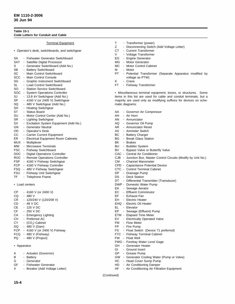
EM 1110-2-300630 Jun 94
Table 15-1Code Letters for Conduit and Cable
Terminal Equipment
• Operator’s desk, switchboards, and switchgear
SA - Fishwater Generator SwitchboardSAT - Satellite Digital ProcessorS - Generator Switchboard (Add No.)SB - Battery SwitchboardSC - Main Control SwitchboardSCC - Main Control ConsoleSG - Graphic Instrument SwitchboardSL - Load Control SwitchboardSO - Station Service SwitchboardSOC - System Operations ControllerSJ - 13.8 kV Switchgear (Add No.)SP - 4160 V (or 2400 V) SwitchgearSQ - 480 V Switchgear (Add No.)SH - Heating SwitchgearST - Status BoardSU - Motor Control Center (Add No.)SR - Lighting SwitchgearSX - Excitation System Equipment (Add No.)GN - Generator NeutralOD - Operator’s DeskCC - Carrier Current EquipmentER - Electrical Equipment Room CabinetsMUX - MultiplexerMW - Microwave TerminalsFSC - Fishway SwitchboardDOC - Digital Operations ControllerROC - Remote Operations ControllerFSP - 4160 V Fishway SwitchgearFCP - 4160 V Fishway ControllerFSQ - 480 V Fishway SwitchgearFSU - Fishway Unit SwitchgearTF - Telephone Frame
• Load centers
CP - 4160 V (or 2400 V)CQ - 480 VCR - 120/240 V (120/208 V)CD - 48 V DCCE - 125 V DCCF - 250 V DCCA - Emergency LightingCH - Preferred ACCY - (CO2) CabinetDQ - 480 V (Dam)FCP - 4160 V (or 2400 V) FishwayFCQ - 480 V (Fishway)PQ - 480 V (Project)
• Apparatus
A - Actuator (Governor)B - BatteryG - GeneratorGF - Fishwater GeneratorX - Breaker (Add Voltage Letter)
T - Transformer (power)Z - Disconnecting Switch (Add Voltage Letter)CT - Current TransformerV - Voltage TransformerEG - Engine GeneratorMG - Motor GeneratorMC - Motor Control CabinetM - MotorPT - Potential Transformer (Separate Apparatus modified by
voltage as PTW)K - CraneFT - Fishway Transformer
• Miscellaneous terminal equipment, boxes, or structures. Someitems in this list are used for cable and conduit terminals, but amajority are used only as modifying suffixes for devices on sche-matic diagrams:
AA - Governor Air CompressorAH - Air HornAN - AnnunciatorAQ - Governor Oil PumpAR - Annunciator ResetAS - Ammeter SwitchBC - Battery ChargerBG - Break Glass StationBK - BrakesBU - Bubbler SystemBV - Bypass Valve or Butterfly ValveCAC - Central Air ConditionerCJB - Junction Box, Master Control Circuits (Modify by Unit No.)CM - Channel ManometerCPD - Capacitance Potential DeviceCTC - Control Terminal CabinetDP - Drainage PumpDS - Deck StationDT - Differential Transmitter (Transducer)DWP - Domestic Water PumpEA - Sewage AeratorEC - Effluent ComminutorEF - Exhaust FanEH - Electric HeaterEHQ - Electric Oil HeaterEL - ElevatorEP - Sewage (Effluent) PumpETM - Elapsed Time MeterEV - Electrically Operated ValveFM - Flow MeterFP - Fire PumpFS - Float Switch (Device 71 preferred)FTC - Fishway Terminal CabinetFW - Float WellFWG - Forebay Water Level GageGH - Generator HeaterGI - Ground InsertGP - Grease PumpGW - Generator Cooling Water (Pump or Valve)HC - Head Cover Sump PumpHD - Air Conditioning DamperHF - Air Conditioning Air Filtration Equipment
(Continued)
15-4
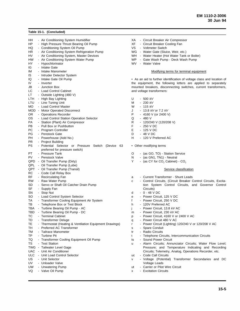
EM 1110-2-300630 Jun 94
Table 15-1. (Concluded)
HH - Air Conditioning System HumidifierHP - High Pressure Thrust Bearing Oil PumpHQ - Conditioning System Oil PumpHR - Air Conditioning System Refrigeration PumpHV - Air Conditioning System, Master DevicesHW - Air Conditioning System Water PumpHY - HypochlorinatorIG - Intake GateIM - Intake ManometerIS - Intruder Detector SystemIQ - Intake Gate Oil PumpIV - InverterJB - Junction BoxLC - Load Control CabinetLT - Outside Lighting (480 V)LTH - High Bay LightingLTU - Line Tuning UnitMO - Load Control MasterMOD - Motor Operated DisconnectOR - Operations RecorderOS - Load Control Station Operation SelectorPA - Station (Plant) Air CompressorPB - Pull Box or PushbuttonPC - Program ControllerPG - Penstock GatePH - Powerhouse (Add No.)PR - Project BuildingPS - Potential Selector or Pressure Switch (Device 63
preferred for pressure switch)PT - Pressure TankPV - Penstock ValveQPD - Oil Transfer Pump (Dirty)QPL - Oil Transfer Pump (Lube)QPT - Oil Transfer Pump (Transil)RC - Code Call Relay BoxRF - Recirculating FanRW - Raw Water PumpSD - Servo or Shaft Oil Catcher Drain PumpSF - Supply FanSN - Stop NutSO - Load Control System SelectorTA - Transformer Cooling Equipment Air SystemTB - Telephone Box or Test BlockTBA - Turbine Bearing Oil Pump - ACTBD - Turbine Bearing Oil Pump - DCTC - Terminal CabinetTD - Transformer DelugeTE - Thermostat (Heating & Ventilation Equipment Drawings)TH - Preferred AC TransformerTM - Tailrace ManometerTP - Turbine PitTQ - Transformer Cooling Equipment Oil PumpTS - Test StationTWG - Tailwater Level GageUAC - Unit Air ConditionerULC - Unit Load Control SelectorUS - Unit SelectorUV - Unloader ValveUW - Unwatering PumpVQ - Valve Oil Pump
XA - Circuit Breaker Air CompressorXF - Circuit Breaker Cooling FanVS - Voltmeter SwitchWG - Water Gate (Sluice, Weir, etc.)WH - Water Heater (Hot Water Tank or Boiler)WP - Gate Wash Pump - Deck Wash PumpWV - Water Valve
Modifying terms for terminal equipment
• As an aid to further identification of voltage class and location ofthe equipment, the following letters are applied to separatelymounted breakers, disconnecting switches, current transformers,and voltage transformers:
U - 500 kVM - 230 kVW - 115 kVJ - 13.8 kV or 7.2 kVP - 4160 V (or 2400 V)Q - 480 VR - 120/240 V (120/208 V)F - 250 V DCE - 125 V DCD - 48 V DCH - 120 V Preferred AC
• Other modifying terms
O - (as GO, TO) - Station ServiceN - (as GN1, TN1) - NeutralY - (as CY for CO2 Cabinet) - CO2
Service classification
a - Current Transformer - Shunt Leadsc - Control Circuits, (Circuit Breaker Control Circuits, Excita-
tion System Control Circuits, and Governor ControlCircuits)
d - 0 - 48 V DCe - Power Circuit, 125 V DCf - Power Circuit, 250 V DCh - 120V Preferred ACj - Power Circuit, 13.8 kV ACm - Power Circuit, 230 kV ACp - Power Circuit, 4160 V or 2400 V ACq - Power Circuit 480 V ACr - Power Circuit (Lighting) 120/240 V or 120/208 V ACs - Spare Conduittr - Radio Circuitst - Telephone Circuits, Intercommunication Circuitsts - Sound Power Circuitu - Alarm Circuits; Annunciator Circuits; Water Flow Level;
Pressure; and Temperature Indicating and RecordingCircuits; Telemetry, Analog, Operations Recorder, etc.
uc - Code Call Circuitsv - Voltage (Potential) Transformer Secondaries and DC
Voltage Leadsut - Carrier or Pilot Wire Circuitx - Excitation Circuits
15-5
EM 1110-2-300630 Jun 94
e. Code identification notes.
(1) The list of letters in paragraph 15-4d(1) is usedfor separately mounted apparatus only. Instrument trans-formers and disconnecting switches are given individualdesignations only if they are mounted by themselves, as inan outdoor structure or in a similar indoor arrangement.
(2) Instrument transformers and disconnectingswitches mounted on a circuit breaker or circuit breakerstructure have the cable and conduit designations of thebreaker. For example, bushing-type current transformersand potential devices mounted on oil circuit breaker XJ3have cable and conduit designations such as “S3-a1-XJ3”and “S3-v1-XJ3”
(3) Cable terminal designations are used to designatemajor assemblies such as a switchgear assembly and notan individual breaker within the switchgear. Individualbreaker designation is desirable, but including it in theterminal designation (first term of cable code) wouldcomplicate the system impairing its usefulness. Thus,instrument transformers, breakers, and disconnectingswitches mounted in a switchgear or switchboard take theterminal designation of the switchgear or switchboard.For example, a breaker mounted in a 480-V switchboardhas a cable and conduit designation of “SQ” for the firstterm and even though the breaker may have a number,this number is disregarded in the first term of the cablecode. Where there are only a few breakers, the lack of amore positive identification is not objectionable.
(4) When a switchboard has a large number ofbreakers, considerable time may be consumed in locatingthe cable. To overcome this objection, the second term ofthe cable code is numbered to correspond with the breakernumber. For example, CQ2-q8 and CQ2-q25 are 480-Vpower circuits connected to breaker No. 8 and No. 25,respectively, in 480-V cabinet No. 2. No difficulty isencountered because the number in the second term servesto differentiate one cable from another and doesn’t indi-cate the total number of cables from a point.
(5) The order of terminal designation follows theorder given in the code. For example, a cable between alighting switchboard and a lighting cabinet is designatedas “SR2-r4-CR5.” The switchboard table precedes theload center table, the switchboard designation being thefirst term and the load center the last term. Other exam-ples would be SJ-j2-G1 and CP-p1-K2. This order ofdesignation is maintained for items of the same table;e.g., SC-a1-SP or A2-c1-G2.
(6) Because of the complicated code, the designa-tion’s primary application is in the powerhouse. Thesame designation may be used with a prefix to signifylocation at a different feature of the project. For example,DCR can represent a lighting cabinet in the dam.
(7) Similarly, FCQ represents a fish facility 480-Vcontrol center. This system is maintained at the power-house for terminal equipment, cables, and conduits servic-ing the fishway next to the powerhouse and also ismaintained partially at the fishway. However, on portionsof the fishway including collection channels, diffusionchambers, and the various gates, it is desirable to usedesignations employed in the structural and mechanicaldesign and having name familiarity. Designations andlocations of these elements of fish facilities are project-specific.
(8) Cable running from one part of the project toanother should be clearly identified. For instance, the4160-V cables originating at the powerhouse and used tosupply power for the fishway, dam, and lock may have adesignation SP - p1 to the first point of connection, SP -p1.1 between the first and second points of connection,and SP - p1.2, and so on, for the subsequent points.
(9) Powerhouse drawings showing the cable runningto the fishway should indicate the cable number and givereference to the fishway drawing in which the other termi-nal of the cable is shown. Similarly, the fishway draw-ings should indicate the cable numbers for the cable inboth directions and references given to both powerhouseand dam drawings.
(10) Wiring diagrams for a large switchboard orswitchgear assembly are on several drawings, so consid-erable time is consumed in locating the proper drawingand the proper panel. To avoid this difficulty, eachswitchboard has its front panels numbered in order fromleft to right. The panel designation is the switchboarddesignation followed by the panel number, and the cablenumber then designates the panel at which it terminates.For example, on Generator Switchboard No. 1, the thirdpanel from the left would be designated “S13” and acable running from this panel has a designation such as,“S13-c1-TO.”
(11) In duplex switchboards, a rear panel is desig-nated by the letter “R” followed by a number correspond-ing to its front panel. For example, on GeneratorSwitchboard No. 1, the third rear panel from the right
15-6
EM 1110-2-300630 Jun 94
(facing the front of the rear panels) is designated “S1R3”and a cable running from this panel has a designationsuch as “S1R3-c1-TO.”
(12) Some vertical sections of a motor control centerassembly may include two or more lighting panels, in oneinstance with the same voltage classification (e.g., CR-rand CA-r). The lighting panel designation is used in lieuof the vertical section number in these instances. Amotor control center could include lighting panels of thefollowing designations:
SU1 - - - CR11, CE11, CF11, CA11, CB11
SU2 - - - CR21, CE21, CF21, CA21, CB21
SU3 - - - CR31, CE31, CF31 CA31, CB31
SU4 - - - CR41, etc.
f. Lighting circuits. With lighting circuits, it is desir-able to deviate from the general plan of providing a rela-tionship between the conduit and its contained circuits.Branch circuits from lighting cabinets are numbered tocomply with the power circuit guide. The numbering ofbranch conduits from lighting cabinets complies with theguide, except the conduit number bears no relationship tothe numbers of the circuits running through it. The con-duit number is initially determined by sequence number-ing in a clockwise direction from the upper right-handcorner when facing the lighting cabinet and is not affectedby circuits and conduits feeding the lighting cabinet.Where more than one row of knockouts is involved, thesequence of numbering is from front to back andclockwise.
15-7
EM 1110-2-300630 Jun 94
Chapter 16Procedure for Powerhouse Design
16-1. Design Initiation
Design for a powerhouse is initiated during engineeringand design activities supporting preconstruction planningstudies. The planning studies accompany reports to Con-gress seeking initial authorization for a project. Theaccompanying studies are either reconnaissance reports orfeasibility studies with an engineering appendix. If favor-able congressional action is received as a result of initialauthorization activities, further engineering and designactivities are conducted including preparation of a GeneralDesign Memorandum (GDM). The GDM is incorporatedinto documentation submitted to higher authority seekinga construction start. ER 1105-2-100 provides furtherinformation on the contents of these reports. Chapter 17describes requirements for the GDM. At each stage ofthe process, powerhouse design is further refined.
16-2. Design Process
After a project has been authorized and funds appropri-ated or allotted for design of the power plant, criteriaoutlined in Guide Specification CE 4000, Appendix A,should be followed regardless of the organization per-forming the design. The criteria outline a process ofpreparation of Feature Design Memorandums covering thedesign features of the power plant, preparation of plansand specifications, and other engineering activitiesinvolved in implementing design, construction, and com-missioning of the power plant. The field operating activ-ity (FOA) can utilize either the Hydroelectric DesignCenter (HDC) or an architect engineer (A-E) to providethe engineering and design services for developing power-house design, preparing plans and specifications, review-ing vendor drawings, assisting in preparation of operationand maintenance manuals, and providing record drawingdocumentation.
16-1
EM 1110-2-300630 Jun 94
Chapter 17General Design Memorandum
17-1. Requirements
Format and content requirements for the General DesignMemorandum (GDM) are described in ER 1105-2-100.The general features of the selected power plant designare presented and analyzed by means of sketches, dia-grams, and cost comparisons. Sketches, diagrams, andcost comparisons are used to explain plan formulation andthe plan selection process. The electrical drawingsrequired for the memorandum, in addition to equipmentlocations shown on general floor plans, consist chiefly ofone-line diagrams. Approximately six to eight drawingsare sufficient to show main unit and switchyard connec-tions, the station service scheme, the control and protec-tive relaying schemes, the communications system, and alighting feeder scheme. Major equipment information,obtained from vendors, should be included in the appen-dixes. If the report is approved, it becomes a guide forsubsequent detailed engineering developed in FeatureDesign Memorandums and design drawings (covered inChapter 18).
17-1
EM 1110-2-300630 Jun 94
Chapter 18Feature Design Memorandums andDrawings
18-1. Design Memorandum Topics and Coverage
Following approval of the General Design Memorandum,engineering, design, and drawing preparation for thepower plant proceed using Feature Design Memorandums(FDM) and accompanying drawings. A completion sche-dule for each of the planned memorandums and asequence of submission is developed for the concurrenceand approval of the field operating activity (FOA) andhigher authority early in the process. Design memoran-dum sequence and submission dates should be coordinatedwith the power plant construction schedule and equipmentprocurement schedules. Timing and sequence of submis-sion are scheduled to maximize review time and alloweffective use of engineering resources of the reviewagency.
18-2. Feature Design Memorandums
FDMs are normally prepared for electrical equipment andsystems purchased by the Government. They are alsoprepared for electrical systems having a significant con-tent of Government-furnished equipment. The plans andspecifications required for purchased equipment are basedon the design parameters and information contained in theFDM. Typical equipment and systems requiring FDMsinclude generators, step-up and station service transform-ers, generator bus and breakers, station service switchgear,power plant energy management systems (SCADA),480-V station service and distribution systems, stationbattery systems, and station lighting and distributionsystems.
18-3. Engineering Documentation
The engineering documentation in FDMs should includethe methods, formulas, detailed computations, and results(if results are obtained from engineering software pro-grams) used to determine equipment and system ratingsand technical design parameters. Design alternativesinvestigated during the equipment or system selectionprocess should be discussed together with the rationale forchoosing the selected alternative. FDMs should containsufficient detail not only to facilitate the checking andreview process, but to allow preparation of plans andspecifications accurately conveying the design intent.
18-4. Design Drawings
Design drawings accompanying an FDM will conform ingeneral to the requirements mentioned in the followingparagraphs.
a. Generators. No design drawings are necessaryfor generators, unless needed to depict unusual generatorlead arrangements, or illustrate connections to and loca-tion of excitation equipment.
b. Transformers. Design drawings for either genera-tor step-up or station service transformers are not requiredwith FDM submission.
c. High-voltage system. Drawings locating theswitchyard with respect to the powerhouse, depictingcable tunnel or cable duct locations, and providing detailson bay widths, types of structures, and phase-to-phase andphase-to-ground clearances should be furnished. A planof the switchyard, including line bay and transformer baysections and a switchyard one-line diagram, will ade-quately convey the design intent.
d. Generator-voltage system. A plan of the arrange-ment of the generator bus and breaker system, togetherwith locating and limiting dimensions, equipment ratings,generator surge protection equipment, and excitation sys-tem power potential system taps, should be provided withthe FDM. In addition, a plant one-line diagram should beprovided.
e. Station service systems. Drawings with arrange-ments, locations, limiting dimensions and one-line dia-grams for medium-voltage switchgear, low-voltageswitchgear, and low-voltage motor control centers of thestation service system should be included with the FDM.
f. Control system. Drawings included with the con-trol system FDM should define the design of the plantenergy management (SCADA) system, the plant controland relay scheme, the control and protective relay switch-boards, and associated equipment. The plans shouldprovide sufficient information regarding control and pro-tective relay functions to convey the intended operationsof the plant’s control and protective relaying systems.Typically, unit one-line diagrams, unit and plant controland protective relaying schematics, station service controland protective relaying schematics, and block diagrams ofthe plant’s energy management system adequately providethis information. In addition, a control room layout, and
18-1
EM 1110-2-300630 Jun 94
a layout with control equipment locations, together withlocating and limiting (if necessary) dimensions, isprovided.
g. Communications systems. A drawing of the extentand composition of leased commercial telephone facilities,the code call system, and dedicated communications sys-tems for utility communications, telemetry, and plantenergy management systems (SCADA) should be pro-vided. Drawings with locations of the commercial tele-phone main distribution frame, code call stations, anddedicated communication system components of either thepower line carrier, microwave system, or the fiber-opticsystem should be provided.
h. Direct current system. In addition to the one-lineand schematics described in paragraph 18-4f, a prelimi-nary layout should be provided of the DC system equip-ment. The drawing should include the rating of batterychargers, inverters, and batteries; any limiting dimensionsof equipment; and the arrangement of the battery cells.
i. Lighting and receptacle systems. Drawings of theplant normal and emergency lighting systems should be
provided. Information regarding connected lighting sys-tem loads, intended feeder sizes, and location of lightingdistribution panels and transformers should be included.In addition, information on intended lighting intensitiesthroughout the plant and proposed types of luminairesshould be provided.
j. Grounding systems. A plan of the power plantground mat, including taps to major equipment, should beprovided. A similar plan should be provided if a separateswitchyard ground mat is included in the projectdevelopment.
k. Conduit and cable tray systems. Design layoutswith locations and preferred methods of routing majorconduit runs (including number and size of conduit)should be provided. Similar layouts should be providedfor the plant’s cable tray systems. These preliminarylayouts form the basis for detailed drawings of thesesystems prepared for the powerhouse constructioncontract.
l. Wire and cable. Design drawings are not preparedfor this phase of the work.
18-2
EM 1110-2-300630 Jun 94
Chapter 19Construction Specifications andDrawings
19-1. Specifications
a. Types of contracts. Construction specifications anddrawings for hydroelectric power plant work are used fortwo different classes of contracts: supply contracts for thepurchase of built-to-order equipment from manufacturers;and construction contracts for the building of the power-house, switchyard, and related structures. When construc-tion begins before engineering and design of all featuresare completed, second- and third-stage construction con-tracts are used to cover the superstructure and/or wiringand installation of machinery and equipment.
b. Selection of contract type. The choice of whetherto include electrical equipment procurement within thepowerhouse construction scope of responsibility, todirectly purchase the required equipment for installationby the contractor (installation only), or to procure design,fabrication, and installation of equipment (“turn-key”) isdependent upon a number of factors. These factorsinclude equipment procurement lead times, the complexityof the fabricated equipment, and the need for specializedinstallation skills. Generally, supply contracts are used toprocure equipment with long lead times, equipment with ahigh degree of complexity, or equipment requiringspecialized installation skills and techniques. Typicalequipment procured with supply contracts includes gener-ators (turn-key procurement), SCADA systems, high-voltage bus and breakers, generation step-up transformers,and generator- and high-voltage power circuit breakers.Low-voltage switchgear, motor control centers, lightingpanels, and cable tray systems are typical of equipmentincluded in a construction scope of supply.
c. Specification preparation. General criteria andpolicies to be observed in preparing specifications arefound in Appendix A of Guide Specification CE-4000.Specifications and plans should be carefully coordinated,and various sections in a given specification (sometimesprepared by different writers) checked to ensure consis-tency, eliminate conflicts, clearly define limits of paymentitems, and avoid overlapping payments for any item.Specifications are prepared to accommodate three classesof users of the specifications: the construction and/ormanufacturing contractor, the resident engineer, and thefield or shop inspector. Specifications for Corps of Engi-neers civil works projects differ from private sector
practices because the specifications and plans must beself-explanatory without amplification about details of theconstruction or equipment fabrication. Typically, privatesector specifications depend on interpretations of theengineering organization designing the project. Privatesector specifications are unsuited to the Corps of Engi-neers’ competitive open bidding methods of awardingcontracts and performing the work.
19-2. Construction Drawings
a. General. Construction drawings should be com-plete and based on commercially available equipment andindustry-recognized construction and installation tech-niques. Details of equipment design and installation,wiring, and conduit should be complete to minimize theneed for field revision. Discussions in the followingparagraphs indicate the type and scope of information thatshould be included on construction drawings for the vari-ous phases of work covered by this chapter.
b. Generators.
(1) Selected or modified drawings from the generalarrangement drawings of the powerhouse are generallyused to accompany the specifications for purchase ofgenerators. Drawings prepared to accompany guide speci-fications should indicate various mechanical and electricalinterfaces including main leads, piping terminations (e.g.,lube oil, cooling water, CO2, brake air), neutral equipmentlocations, and excitation system equipment locations.
(2) A plant or main unit one-line diagram shouldalso be included in the procurement drawing set. Equip-ment centerline should be dimensioned from structurelines. Powerhouse crane hook coverage should be shownon the appropriate procurement drawing set. Other gov-erning or limiting dimensions should be established.Locations and dimensions of openings, sleeves, and inter-fering equipment should be shown where possible. Incases where dimensions cannot be determined until later,the dimension lines should be drawn in and indicationmade that the dimension will be added at a later date.Generator procurement drawings may be included in theconstruction contract set to show the extent of generatorerection performed by the generator supplier.
c. Transformers.
(1) Suitable drawings showing the location andgeneral arrangement of the transformers and connectingbus structures and limits of work under the contract
19-1
EM 1110-2-300630 Jun 94
should be included with the transformer procurementspecifications.
(2) The drawings should include all features notadequately covered in the specifications affecting thedesign of the transformers or powerhouse, such as limit-ing transformer dimensions, rails and other provisions forlifting and moving the transformers, locations of terminalcabinets, surge arresters, chilling sumps and wallsbetween transformers, bushing enclosures for connectionto metal-enclosed bus, and location of heat exchangers.Other details include size of oil pipes for Class FOWtransformers where the heat exchangers will be installedremotely from the transformers, types and sizes of bush-ing terminal connectors, and provisions for grounding theneutrals of the high-voltage windings and the transformertanks.
d. High-voltage system. Construction drawings forthis system should show all necessary layouts and detailsfor installation of equipment from the high-voltage bush-ings of the transformers to the outgoing transmission lineinterface in the switchyard. These plans should includedrawings of the high-voltage leads with details of termina-tion points; switchyard equipment arrangement drawings,including plans, sections, elevations, and details; structureloading diagrams; conduit and grounding plans; anddetails of lighting and power panels and other miscella-neous equipment. A one-line diagram of the high-voltagesystem should be prepared, together with control schemat-ics of controlled equipment. Manufacturers’ shop draw-ings are used to a great extent in the actual installation ofequipment.
e. Generator-voltage system. Drawings for the gener-ator-voltage system should show sufficient details forpurchase of the generator main and neutral leads andassociated equipment, and the generator switchgear ifincluded in the supply scope. The drawings should showthe general layout, details of arrangement and ratings ofequipment, limiting dimensions, termination methods, anda one-line diagram showing items of equipment. If thesupply scope includes generator switchgear, control sche-matics of the controlled equipment should be provided.These drawings are also included with the drawings forthe construction contract to show the extent of the instal-lation work. Manufacturers’ detail drawings are used forinstallation of this equipment.
f. Station service systems.
(1) General. Construction drawings for the stationservice system should consist of the station service
one-line diagram and drawings used for purchase of theswitchgear and motor control centers, if supply of thisequipment is not included in the construction scope ofsupply.
(2) Station service switchgear.
(a) The station service switchgear drawings shouldshow all information necessary for design of the switch-gear and, insofar as possible, the information needed forinstallation.
(b) The switchgear drawings should indicate theframe size and ampere rating of each breaker, as well asthe nameplate designation of each circuit. Wire sizes ofoutgoing feeders should be provided for correct sizing ofcircuit breaker lugs. The number and rating of currentand potential transformers should be indicated. The pre-ferred layout of indicating and control equipment shouldbe shown.
(c) A one-line diagram should be prepared of theswitchgear line-up. Centerline dimensions and preferredrouting of any bus included in the switchgear scope ofsupply should be provided.
(d) Drawings showing the switchgear installationshould be prepared with sufficient arrangement flexibilityto accommodate variations in dimensions among equip-ment suppliers. Drawings prepared for the purchase ofthe switchgear are also included in the contract construc-tion drawings to indicate the scope and complexity ofinstallation and connection. Manufacturers’ shop draw-ings are used for installation of the switchgear.
(3) Motor control centers.
(a) Drawings for motor control centers are similar inscope to the drawings of the switchgear. Motor controlcenters consist of free-standing cubicles containing combi-nations of standardized factory subassemblies. The stan-dardized units described in Chapter 7 are preferred.
(b) Outside dimensions of embedded cabinets andlocations of conduits for supply and branch circuits shouldbe shown. Motor control center elevations indicatingpreferred location of starters, control switches, and name-plates should be shown. A one-line diagram with therelative positions of equipment enclosed within the controlcenter, direction of bus runs, the location of bus lugs, andthe ratings of all equipment should be provided.
19-2
EM 1110-2-300630 Jun 94
(c) The drawings should contain tabulations of thecircuit number, the nameplate designation of the circuit,the expected load, the breaker frame size, the starter size,and the number and size of conductors.
(4) Lighting and power panelboards.
(a) The purchase and installation of lighting andpower panels are included in the powerhouse constructioncontract. Drawings are prepared showing the size of theembedded cabinets, the size of the front covers, bus dia-grams, and any pertinent details such as space allocationand wiring diagrams for throw-over switches or remotecontrol switches located in the panels. Tabulations ofmain bus current ratings, main breaker ratings, locationand sizes of main and neutral lugs, and the number andratings of branch-circuit breakers should be included onthe drawings.
(b) Lighting plan circuit designations should be pro-vided on the panel bus diagrams. Panel layouts shouldprovide space for spare and future circuit breakers.
(c) Doors, locks, and details of door openings shouldbe shown. Front covers should overlap the embeddedcabinet approximately 1 in. all around. All contactorsshould be completely separated by barriers from otherequipment and from wire gutters.
(d) Buses should also be completely enclosed exceptat the ends of runs. The necessity for the removablecover over the bus lugs should be considered in locatingequipment within the cabinet.
g. Control system. Drawings issued for purchase ofswitchboards, control panels, and the operator’s controlconsole (if required), comprising the plant control system,should include plant and unit one-line diagrams, plant andunit control and protective relay schematics, station ser-vice control and protective relay schematics, and associ-ated equipment. Other drawings that should be in thedrawing package include switchboard and control consolearrangements showing preferred locations of relays,instruments, and control switches. Preparation of wiringdiagrams for this equipment should be included in themanufacturer’s scope of supply, together with the prepara-tion of terminal connection diagrams to which externalplant interconnection details can be added during the shopdrawing review process. If a plant energy managementsystem (SCADA) is incorporated in the control systemprocurement, block diagrams of the system should beincorporated with the procurement drawing set. Controlsystem drawings are also incorporated in the construction
drawing set for information as to the extent of the instal-lation work. Actual installation of the control systemshould be performed in accordance with the manufac-turer’s approved drawings. Included in the constructionset should be drawings providing locating dimensions forcontrol system equipment.
h. Annunciation system. Generally, annunciators areincluded in the scope of supply for the control switch-boards. A drawing of the incoming trouble and alarmpoints to the annunciators, together with preferred windowarrangements and window legends, should be provided.Incoming trouble, alarm, and event points to the plantsequence-of-event recorder (SER), together with a pre-ferred format for printout of recorded events, should beprovided on the drawings.
i. Communications system. Drawings that define thescope of facilities that will permit the installation of com-munication termination equipment should be included inthe construction drawing set. The construction contractorwill provide the facilities. The communication termina-tion equipment will be furnished and installed by others(see Chapter 10). In addition, a drawing with locations ofthe plant’s code call system should be prepared.
j. Direct current system. The drawing for the pur-chase of the battery switchboard is similar in scope tothose for the equipment discussed in paragraph 19-2g.The battery switchboard is generally purchased with thecontrol switchboard. The battery switchboard drawing isincluded with the construction contract drawings to depictthe extent of the work and provide explanatory material.
k. Lighting and receptacle systems.
(1) Lighting drawings on the lighting plan for anarea should show all fixture, switch, and receptacle out-lets, and all conduits in the walls and ceiling.
(2) Conduits in the ceiling and walls of an area areshown on a floor plan of that area. Conduit in the floorslab for the same area, even though used to feed outlets inthe area, should be shown on another plan as in the ceil-ing for the area below.
(3) Building and room outlines, beams, and open-ings, should be shown. Rooms should be identified.Normally, it is not necessary to show equipment on light-ing drawings. Sections and details should be shownwhere necessary for clarification. Wiring diagrams andequipment should be detailed in accordance with thedrawing legend. All outlets, junction boxes, and conduit
19-3
EM 1110-2-300630 Jun 94
terminations should be located by dimensions and, ifnecessary, by elevations.
(4) The conduit system should be detailed completelyand all sizes and materials noted. Embedded conduit forbranch circuits should be limited to ¾- and 1-in. sizes ifpossible. Conduits serving ceiling fixtures in areas withsuspended ceilings should be stubbed out of the concrete.The conduit will be extended to fixture outlet boxesbefore placing the ceiling suspension system.
(5) Boxes, extension rings, and covers should besuited to the finish of the space in which they are usedwith appropriate notations or details made on the draw-ings to ensure the use of the proper materials and fittings.Wall outlet boxes should be sheet metal boxes with suit-able extension rings when located above the generatorroom floor. On turbine room walls, boxes should be castboxes meeting the requirements of UL 514A.
(6) Complete details should be given for lighting fix-ture mountings, wiring devices, and device plates. Circuitsshould be designated by lighting panel number and circuitnumber and balanced across the lighting panel buses andtransformer. The number and sizes of wires in each con-duit are indicated by standard hash marks and notes. Thesystem should be color-coded as noted on the typicaldrawing.
(7) To avoid confusion, local switches and their con-trolled fixtures should have an individual letter designa-tion to indicate their relation. Fixture, switch, andreceptacle types should be designated on the drawings andreferred to a schedule giving the fixture type by referenceto a catalog product or to a detail drawing. The scheduleshould also show all mounting fittings.
l. Grounding systems. Grounding system drawingsshould include all plans, information, and details neces-sary for the installation of the power plant ground mat,the main powerhouse grounding network, and taps andconnections to equipment. The taps from the mainground network to equipment may be shown convenientlyon the power and control conduit plans. Details shouldinclude test stations if used, water seals, exposed groundbus supports, and typical connections to the frame orhousing of plant equipment and metal structures.
m. Conduit and cable tray systems.
(1) Conduit plans for station service power and for allcontrol circuits, including the communication system,should show the conduits in the floor and walls of the
designated area. Obstructions, structural features, andlocations of equipment influencing conduit location shouldbe shown on the drawings.
(2) Conduits should be in accordance with the leg-end. Each conduit should be labeled with the size andconduit number shown in the conduit and cable schedule.Conduit termination locations should be dimensioned tobuilding control lines wherever possible.
(3) All outlet boxes and cabinets should be shownon the drawings with size, location, and, if applicable,designation numbers given. Any required boxes shouldbe located and detailed.
(4) Where a number of conduits stub out of a wallor floor within a small area, a structural steel terminalplate should be detailed for use in holding the conduitsrigidly in place during concrete placement operations. Ifconduit locations are not known when the drawings areprepared, indication should be made that dimensions willbe furnished at a later date.
(5) Sufficient elevations and details of conduitsentering junction boxes, pull boxes, or cabinets should beprovided showing the complexity of the work and thequality and size of allowable electrical construction mate-rials. Where stubs are left in concrete walls or ceilingsfor exposed runs to equipment, the conduit should bestubbed flush with a coupling and closed with a pipe plug.
(6) One or two spare conduits should be run fromeach motor control center or lighting panel wall locationto 6 in. below the ceiling of the room in which the instal-lation is located and terminated in a flush coupling. Oneor more spare conduits should be similarly terminated inthe room below the installation.
(7) Pull boxes, embedded power cabinets, and junc-tion boxes should be completely detailed to show size,material, flange width, front covers, and conduit drilling.For cast iron boxes, a standard catalog product withdrilled and tapped conduit entrances is specified.
(8) Drawings should show the arrangement andlocation of the complete tray system. Details of trayhangers, supports and splices, and supporting blocks forcables entering or leaving the trays, should be shown onthe drawings. The trays should be suitably identified forlisting in cable schedule references. Construction detailsof all fabricated components should be provided on thedrawing. Component totals should be included on a billof materials.
19-4

EM 1110-2-300630 Jun 94
n. Wire and cable. The cable and conduit scheduleshould be prepared as outlined in Chapter 15. It is con-venient to list the multiconductor control cables separatelyfrom power cables. Computer-generated spreadsheets aregenerally used for listing all power plant power, control,and communications cables. The locations of wire andcable in trays should be shown on tray diagrams. Thesediagrams will expedite construction and provide “as con-structed” engineering documentation useful for plantmaintenance.
19-5
EM 1110-2-300630 Jun 94
Chapter 20Analysis of Design
20-1. Permanent Record
The “Analysis of Design” memorandum should be apermanent record for future reference. It should consoli-date into one document engineering information andcomputations from previously approved design memoran-dums pertinent to the executed plans and specifications.
20-2. Up-To-Date Values
Original computations based on assumed values formachine or equipment characteristics are revised to reflectup-to-date values based either on the manufacturers’design calculations or on field or factory testmeasurements.
20-3. Expansion
If provisions are made in the powerhouse or switchyarddesign for future addition of units, transmission lines, orauxiliary equipment, the Analysis of Design memorandumshould detail the provisions for the expansion.
20-1

EM 1110-2-300630 Jun 94
Appendix AReferences
A-1. Required Publications
TM 5-810-1Mechanical Design, HVAC
ER 1105-2-100Guidance for Conducting Civil Works Planning Studies
ER 1110-2-103Strong Motion Instrument for Recording EarthquakeMotions on Dams
EM 1110-2-3001Planning and Design of Hydroelectric Power PlantStructures
EM 1110-2-4205Hydroelectric Power Plant Mechanical Design
CE 4000Civil Works Guide Specification for Lump Sum Contractfor Engineering Services for Design of HydroelectricPower Plant
CW-13331Civil Works Guide Specification for Supervisory Controland Data Acquisition Equipment
CW-16120Civil Works Guide Specification for Insulated Wire andCable
CW-16211Civil Works Guide Specification for Rewind ofHydraulic-Turbine-Driven Alternating Current Generators
CW-16252Civil Works Guide Specification for Governors forHydraulic Turbines and Pump Turbines
CW-16320Civil Works Guide Specification for Power Transformers
AIEE Transactions on Power Apparatus and Systems,1953 (Oct)Characteristics of Split-Phase Currents as a Source ofGenerator Protection, Paper 53-314.
ANSI C2-1993National Electrical Safety Code
ANSI C37.06-1987American National Standard for Switchgear - AC High-Voltage Circuit Breakers Rated on a Symmetrical CurrentBasis - Preferred Ratings and Related RequiredCapabilities
ANSI C37.16-1980American National Standard Preferred Ratings, RelatedRequirements, and Application Recommendations forLow-Voltage Power Circuit Breakers and AC PowerCircuit Protectors
ANSI C37.90.1-1989IEEE Standard Surge Withstand Capability (SWC) Testfor Protective Relays and Relay Systems (ANSI)
ANSI C80.1-1983Rigid Steel Conduit-Zinc Coated
ANSI C84.1-1989American National Standard Voltage Ratings for ElectricPower Systems and Equipment (60 Hz)
ANSI/IEEE 242-1986IEEE Recommended Practice for Protection and Coordi-nation of Industrial and Commercial Power Systems
ANSI/ISA S18.1-1981Annunciator Sequence and Specifications
EPRI EL-5036Power Plant Electrical Reference Series, Vol. 2, “PowerTransformers”
EPRI EL-5036Power Plant Electrical Reference Series, Vol. 4, “Wireand Cable”
EPRI EL-5036Power Plant Electrical Reference Series, Vol. 5, “Ground-ing and Lightning Protection”
EPRI EL-5036Power Plant Electrical Reference Series, Vol. 9,“DC Distribution”
A-1
EM 1110-2-300630 Jun 94
EPRI EL-5036Power Plant Electrical Reference Series, Vol. 10, “Electri-cal and Instrumentation”
EPRI EL-5036Power Plant Electrical Reference Series, Vol. 13,“Communications”
EPRI TR-101710, 1993EPRI Lighting Fundamentals Handbook
IEEE Transactions on Power Apparatus and Systems,1983IEEE Transactions on Power Apparatus and Systems,1983, Vol PAS-102, No. 9 (September).
IEEE Transactions on Power Apparatus and Systems,1983IEEE Transactions on Power Apparatus and Systems,1983, Vol PAS-102, No. 10 (October).
IEEE 43-1974IEEE Recommended Practice for Testing Insulation Resis-tance of Rotating Machinery (ANSI)
IEEE 80-1986IEEE Guide for Safety in AC Substation Grounding(ANSI)
IEEE 81-1983IEEE Guide for Measuring Earth Resistivity, GroundImpedance, and Earth Surface Potentials of a GroundSystem
IEEE 115-1983IEEE Test Procedures for Synchronous Machines (ANSI)
IEEE 142-1991IEEE Recommended Practice for Grounding of Industrialand Commercial Power Systems (ANSI)
IEEE 399-1990IEEE Recommended Practice for Power Systems Analysis
IEEE 422-1986IEEE Guide for Design and Installation of Cable Systemsin Power Generating Stations (ANSI)
IEEE 450-1987IEEE Recommended Practice for Maintenance, Testing,and Replacement of Large Lead Storage Batteries forGenerating Stations and Substations (ANSI)
IEEE 484-1987IEEE Recommended Practice for Installation Design andInstallation of Large Lead Storage Batteries for Generat-ing Stations and Substations (ANSI)
IEEE 485-1983IEEE Recommended Practice for Sizing of Large LeadStorage Batteries for Generating Stations and Substations(ANSI)
IEEE 605-1987IEEE Guide for Design of Substation Rigid-BusStructures (ANSI)
IEEE 946-1992IEEE Recommended Practice for the Design of DC Auxil-iary Power Systems for Generating Stations
IEEE 979-1984 (Reaffirmed 1988)IEEE Guide for Substation Fire Protection (ANSI)
IEEE 980-1987IEEE Guide for Containment and Control of Oil Spills inSubstations (ANSI)
IEEE 1010-1987IEEE Guide for Control of Hydroelectric Power Plants(ANSI)
IEEE C37.013-1988IEEE Standard for AC High-Voltage Generator CircuitBreakers Rated on a Symmetrical Current Basis (ANSI)
IEEE C37.122 (with Supplement .122a)-1983IEEE Standard for Gas Insulated Substations (ANSI)
IEEE C37.123-1991IEEE Guide to Specification for Gas-Insulated SubstationEquipment (ANSI)
IEEE C37.2Electrical Power System Device Function Numbers
IEEE C37.20.2-1987IEEE Standard for Metal-Clad and Station-Type CubicleSwitchgear (ANSI)
IEEE C37.23-1987IEEE Standard for Metal-Enclosed Bus and CalculatingLosses in Isolated-Phase Bus (ANSI)
A-2
EM 1110-2-300630 Jun 94
IEEE C37.91-1985 (Reaffirmed 1990)IEEE Guide for Protective Relay Applications to PowerTransformers (ANSI)
IEEE C37.95-1989Guide for Protective Relaying of Utility Customer Inter-connections (ANSI)
IEEE C37.96-1988IEEE Guide for AC Motor Protection (ANSI)
IEEE C37.97-1979 (Reaffirmed 1990)IEEE Guide for Protective Relay Applications to PowerSystems Buses (ANSI)
IEEE C37.101-1985 (Reaffirmed 1990)IEEE Guide for Generator Ground Protection (ANSI)
IEEE C37.102-1987 (Reaffirmed 1991)IEEE Guide for AC Generator Protection
IEEE C37.106-1987IEEE Guide for Abnormal Frequency Protection forPower Generating Plants (ANSI)
IEEE C57.12.00-1987IEEE Standard General Requirements for Liquid-Immersed Distribution, Power, and Regulating Trans-formers (ANSI)
IEEE C57.12.11-1980IEEE Guide for Installation of Oil-Immersed Trans-formers (10MVA and Larger, 69 kV - 287 kV Rating)(ANSI)
IEEE C57.12.14-1982IEEE Trial Use Standard for Dielectric Test Requirementfor Power Transformers for Operation at System Voltagefrom 115 kV through 230 kV
IEEE C57.12.90-1987IEEE Standard Test Code for Liquid-Immersed Distribu-tion. Power, and Regulating Transformers; and Guide forShort-Circuit Testing of Distribution and Power Trans-formers (ANSI)
IEEE C57.19.01-1991IEEE Standard Performance Characteristics and Dimen-sions for Outdoor Apparatus Bushings (ANSI)
IEEE C57.98-1986IEEE Guide for Transformer Impulse Tests (ANSI)
IEEE C57.104-1991IEEE Guide for the Interpretation of Gases Generated inOil-Immersed Transformers
IEEE C57.116-1989IEEE Guide for Transformers Directly Connected to Gen-erators (ANSI)
IEEE C57.120-1991IEEE Standard Loss Evaluation Guide for Power Trans-formers and Reactors (ANSI)
IEEE C62.1-1989IEEE Standard for Gapped Silicon-Carbide SurgeArresters for AC Power Circuits (ANSI)
IEEE C62.11-1987IEEE Standard for Metal-Oxide Surge Arresters forAC Power Circuits (ANSI)
IEEE C62.2-1987IEEE Guide for the Application of Gapped Silicon-Carbide Surge Arresters for Alternating Current Systems(ANSI)
IEEE C62.92.2-1989IEEE Guide for Grounding in Electrical Utility Systems,Part II - Grounding of Synchronous Generator Systems(ANSI)
IES-RP-24-1989VDT Lighting
NEMA PE 1-1983Uninterruptible Power Systems
NEMA PE 5-1985Utility Type Battery Chargers
NEMA PE 7-1985Communication Type Battery Chargers
NEMA WC 50-1976Ampacities, Including Effect of Shield Losses for Single-Conductor Solid-Dielectric Power Cable 15 kV through69 kV
NEMA WC 51-1986Ampacities of Cables in Open-Top Cable Trays
NFPA 70-1993“National Electric Code,” Article 480
A-3
EM 1110-2-300630 Jun 94
NFPA 101-1991Code for Safety to Life from Fire in Buildings andStructures
UL 50-1980Cabinets and Boxes
UL 489-1986The Standard for Molded-Case Circuit Breakers andCircuit-Breaker Enclosures
UL 1072-1988The Standard for Medium-Voltage Power Cables
UL 1569-1985The Standard for Metal-Clad Cables
Dawes, C. A.Dawes, Chester A.,Electrical Engineering, Vol II, Alter-nating Currents,McGraw Hill Book Co., 1947.
Fitzgerald and Kingsley, Jr.Fitzgerald, A. E., and Kingsley, Charles Jr.,ElectricMachinery,McGraw Hill, 1961.
KaufmanKaufman, J. E., ed.IES Lighting Handbook. New York:Illuminating Engineering Society (IES); ReferenceVolume, 1984.
Kent 1950Kent, William 1950. “Mechanical Engineers Handbook,”John Wiley and Sons, Inc.
Marks 1951Marks, Lionel S. 1951. “The Mechanical Engineers’Handbook,” McGraw-Hill Book Co., New York.
Puchstein, Lloyd, and ConradPuchstein, A. F., Lloyd, T. C., Conrad, A. G.AlternatingCurrent Machines,John Wiley & Sons, 1954.
A-2. Related Publications
ER 1105-2-100Guidance for Conducting Civil Works Planning Studies
ETL 1110-3-376Telephone System
ANSI C2-1993National Electric Safety Code
ANSI C37.12-1981American National Standard Guide Specifications for ACHigh-Voltage Circuit Breakers Rated on a SymmetricalCurrent Basis and Total Current Basis
ANSI C37.32-1979American National Standard Schedules of Preferred Rat-ings, Manufacturing Specifications and Application Guidefor High-Voltage Air Switches, Bus Supports, and SwitchAccessories
ANSI C50.12-1982American National Standard Requirements for Salient-Pole Synchronous Generators and Generator/Motors forHydraulic Turbine Applications
ANSI C84.1-1989American National Standard Voltage Ratings for ElectricPower Systems and Equipment (60 Hz)
ANSI C93.1-1972Requirements for Powerline Coupling Capacitors
ANSI C93.2-1976Requirements for Powerline Coupling Capacitor VoltageTransformers
ANSI C93.3-1981Requirements for Powerline Carrier Traps
ANSI/NFPA 851-1987Recommended Practice for Fire Protection for Hydroelec-tric Generating Plants
EPRI EL-5036Power Plant Electrical Reference Series, Vols. 1, 2, 3, 5,7, and 8.
Electric Utility Engineering Reference BookElectric Utility Engineering Reference Book - DistributionSystems, Volume 3, available from:
ABB Power T&D Services Co1021 Main Campus DriveRaleigh, NC 27606
IEEE 1-1986General Principles Upon Which Temperature Limits areBased in the Rating of Electric Machines and OtherEquipment
A-4

EM 1110-2-300630 Jun 94
IEEE 32-1972IEEE Standard Requirements Terminology and Test Pro-cedures for Neutral Grounding Devices (ANSI)
IEEE 56-1977IEEE Guide for Insulation Maintenance of Large ACRotating Machinery (10,000 kVA and larger) (ANSI)
IEEE 80-1986IEEE Guide for Safety in AC Substation Grounding(ANSI)
IEEE 94-1991IEEE Recommended Definitions of Terms for AutomaticGeneration Control on Electric Power Systems
IEEE 95-1977IEEE Recommended Practice for Insulation Testing ofLarge AC Rotating Machinery with High Direct Voltage(ANSI)
IEEE 141-1986IEEE Recommended Practice for Electric Power Distribu-tion for Industrial Plants (ANSI)
IEEE 242-1986IEEE Recommended Practice for Protection and Coordi-nation of Industrial and Commercial Power Systems(ANSI)
IEEE 275-1981IEEE Recommended Practice for Thermal Evaluation ofInsulation Systems for AC Electric Machinery EmployingForm-Wound Pre-Insulated Stator Coils, Machines Rated6900 V and Below (ANSI)
IEEE 281-1984IEEE Standard Service Conditions for Power SystemCommunication Equipment (ANSI)
IEEE 286-1975IEEE Recommended Practice for Measurement of PowerFactor Tip-Up of Rotating Machinery Stator Coil Insula-tion (ANSI)
IEEE 367-1987IEEE Recommended Practice for Determining the ElectricPower Station Ground Potential Risk and Induced Voltagefrom a Power Fault (ANSI)
IEEE 400-1991IEEE Guide for Making High-Direct-Voltage Tests onPower Cable Systems in the Field (ANSI)
IEEE 421.1-1986IEEE Standard Definitions for Excitation Systems forSynchronous Machines (ANSI)
IEEE 421.2-1990IEEE Guide for Identification, Testing, and Evaluation ofthe Dynamic Performance of Excitation Control Systems(ANSI)
IEEE 421B-1979IEEE Standard for High-Potential Test Requirements forExcitation Systems for Synchronous Machines (ANSI)
IEEE 422-1986IEEE Guide for Design and Installation of Cable Systemsin Power Generating Stations (ANSI)
IEEE 433-1974IEEE Recommended Practice for Insulation Testing ofLarge AC Rotating Machinery with High Voltage at VeryLow Frequency (ANSI)
IEEE 434-1973IEEE Guide for Functional Evaluation of Insulation Sys-tems for Large High-Voltage Machines (ANSI)
IEEE 446-1987IEEE Recommended Practice for Emergency and StandbyPower Systems for Industrial and Commercial Applica-tions (ANSI)
IEEE 487-1987IEEE Recommended Practice for the Protection of WireLine Communications Facilities Serving Electric PowerStations
IEEE 487-1992IEEE Recommended Practice for the Protection of WireLine Communications Facilities Serving Electric PowerStations
IEEE 492-1974IEEE Guide for Operation and Maintenance of HydroGenerators (ANSI)
IEEE 525-1992IEEE Guide for Design and Installation of Cable Systemsin Substations
IEEE 643-1980IEEE Guide for Power-Line Carrier Applications (ANSI)
A-5
EM 1110-2-300630 Jun 94
IEEE 665-1987IEEE Guide for Generating Station Grounding (ANSI)
IEEE 693-1984IEEE Recommended Practices for Seismic Design ofSubstations (ANSI)
IEEE 739-1984IEEE Recommended Practice for Energy Conservationand Cost-Effective Planning in Industrial Facilities (ANSI)
IEEE 789-1988IEEE Standard Performance Requirements for Communi-cations and Control Cables for Application in HighVoltage Environments (ANSI)
IEEE 810-1987IEEE Standard for Hydraulic Turbine and GeneratorIntegrally Forged Shaft Couplings and Shaft Runout Tol-erances (ANSI)
IEEE 944-1986IEEE Application and Testing of Uninterruptible PowerSupplies for Power Generating Stations (ANSI)
IEEE 979-1984IEEE Guide for Substation Fire Protection (ANSI)
IEEE 980-1987IEEE Guide for Containment and Control of Oil Spills inSubstations (ANSI)
IEEE 999-1992IEEE Recommended Practice for Master/Remote Super-visory Control and Data Acquisition (SCADA)Communication
IEEE 1020-1988IEEE Guide for Control of Small Hydroelectric PowerPlants (ANSI)
IEEE 1050-1989IEEE Guide for Control Equipment Grounding in Gener-ating Stations
IEEE 1095-1989IEEE Guide for Installation of Vertical Generators andGenerator/Motors for Hydroelectric Applications
IEEE 1119-1988IEEE Guide for Fence Safety Clearances in Electric-Supply Stations (ANSI)
IEEE C37.010 (with Supplements .010 b and e)-1979IEEE Application Guide for AC High-Voltage CircuitBreakers Rated on a Symmetrical Current Basis (ANSI)
IEEE C37.011-1979IEEE Application Guide for Transient Recovery Voltagefor AC High-Voltage Circuit Breakers Rated on a Sym-metrical Current Basis (ANSI)
IEEE C37.04 (with Supplements .04 f, g, h)-1979IEEE Standard Rating Structure for AC High-VoltageCircuit Breakers Rated on a Symmetrical Current Basis(ANSI)
IEEE C37.081-1981IEEE Guide for Synthetic Fault Testing of AC High-Voltage Circuit Breakers Rated on a Symmetrical CurrentBasis (ANSI)
IEEE C37.09 (with Supplements .09 c and e)-1979IEEE Standard Test Procedure for AC High-VoltageCircuit Breakers Rated on a Symmetrical Current Basis(ANSI)
IEEE C37.1-1987IEEE Standard Definitions, Specification, and Analysis ofSystems Used for Supervisory Control, Data Acquisitionand Automatic Control (ANSI)
IEEE C37.11-1979IEEE Application Guide for Transient Recovery Voltagefor AC High-Voltage Circuit Breakers Rated on a Sym-metrical Current Basis (ANSI)
IEEE C37.13-1990IEEE Standard for Low-Voltage AC Power CircuitBreakers Used in Enclosures (ANSI)
IEEE C37.14-1979IEEE Standard for Low-Voltage DC Power CircuitBreakers Used in Enclosures (ANSI)
IEEE C37.20.1-1987IEEE Standard for Metal-Enclosed Low-Voltage PowerCircuit Breaker Switchgear (ANSI)
IEEE C37.29-1981IEEE Standard for Low-Voltage AC Power Circuit Pro-tectors Used in Enclosures (ANSI)
A-6

EM 1110-2-300630 Jun 94
IEEE C37.30-1992IEEE Standard Definitions and Requirements for High-Voltage Air Switches
IEEE C37.34 (with Supplements .34 a, b, d, and e)-1979IEEE Standard Test Code for High-Voltage Air Switches(ANSI)
IEEE C37.35-1976IEEE Guide for the Application, Installation, Operation,and Maintenance of High-Voltage Air Disconnecting andLoad Interrupter Switches (ANSI)
IEEE C37.36B-1990IEEE Guide to Current Interruption with Horn-Gap AirSwitches (ANSI)
IEEE C37.37-1979IEEE Standard Loading Guide for AC High-VoltageSwitches (in excess of 1000 volts) (ANSI)
IEEE C37.38-1989IEEE Standard for Gas-Insulated Metal-Enclosed Discon-necting, Interrupter, and Grounding Switches
IEEE C39.96-1988IEEE Guide for AC Motor Protection (ANSI)
IEEE C57.12.01-1989IEEE Standard General Requirements for Dry-Type Dis-tribution and Power Transformers Including Those withSolid Cast and/or Resin-Encapsulated Windings (ANSI)
IEEE C57.12.12-1980IEEE Guide for Installation of Oil-Immersed EHV Trans-formers 345 kV and Above (ANSI)
IEEE C57.13.1-1981 (Reaffirmed 1986)IEEE Guide for Field Testing of Relaying Current Trans-formers (ANSI)
IEEE C57.19.00-1991IEEE General Requirements and Test Procedure for Out-door Power Apparatus Bushings (ANSI)
IEEE C57.19.101-1989IEEE Trial-Use Guide for Loading Power ApparatusBushings
IEEE C57.92-1981IEEE Guide for Loading Mineral-Oil-Immersed Power
Transformers up to and Including 100 MVA with 55 °Cor 65 °C Winding Rise (ANSI)
IEEE C57.94-1982IEEE Recommended Practice for Installation, Application,Operation and Maintenance of Dry-Type General PurposeDistribution and Power Transformers (ANSI)
IEEE C57.106-1991IEEE Guide for Acceptance and Maintenance of Insulat-ing Oil in Equipment
IEEE C57.109-1985IEEE Guide for Transformer Through-Fault Current Dura-tion (ANSI)
IEEE C57.113-1991IEEE Guide for Partial Discharge Measurement in Liquid-Filled Power Transformers and Shunt Reactors
IEEE C57.114-1990IEEE Seismic Guide for Power Transformers andReactors (ANSI)
IEEE C57.115-1991IEEE Guide for Loading Mineral-Oil-Immersed PowerTransformers Rated in Excess of 100MVA (65C WindingRise) (ANSI)
IEEE C62.22-1991IEEE Guide for the Application of Metal-Oxide SurgeArresters for Alternating Current Systems (ANSI)
IEEE C62.92-1987IEEE Guide for the Application of Neutral Grounding inElectric Utility Systems, Part I-Introduction (ANSI)
IEEE C62.92.1-1987IEEE Guide for the Application of Neutral Grounding inElectric Utility Systems, Part I - Introduction (ANSI)
IEEE C62.92.2-1989IEEE Guide for the Application of Neutral Grounding inElectric Utility Systems, Part II-Grounding of Synchro-nous Generator Systems (ANSI)
IEEE C62.92.5-1992IEEE Guide for the Application of Neutral Grounding inElectric Utility systems, Part V - Transmission Systemsand Subtransmission Systems
A-7
EM 1110-2-300630 Jun 94
NEMA ICS 1-1983Industrial Control and Systems
NEMA ICS 2-1988Industrial Control Devices, Controllers and Assemblies
NEMA ICS 6-1983Enclosures for Electrical Controls and Systems
NEMA PB 1-1990Panelboards
NEMA PB 2-1989Deadfront Distribution Switchboards
NEMA ST 20-1986Dry-Type Transformers for General Applications
NEMA VE 1-1984Metallic Cable Tray Systems
NEMA WC 50-1976Ampacities, Including Effect of Shield Losses for Single-Conductor Solid-Dielectric Power Cable 15 kV through69 kV
NEMA WC 51-1986Ampacities of Cables in Open-Top Cable Trays
NEMA WD 1-1983Wiring Devices
NFPA 70-1993National Electrical Code
UL 6-1981Rigid Metal Conduit
UL 467-1984Grounding and Bonding Equipment
UL 514B-1982Fittings for Conduit and Outlet Boxes
UL 845-1987The Standard for Motor Control Centers
UL 1066-1985The Standard for Low-Voltage AC and DC Power CircuitBreakers Used in Enclosures
UL 1072-1988The Standard for Medium-Voltage Power Cables
UL 1236-1986The Standard for Battery Chargers
UL 1277-1988The Standard for Electrical Power and Control TrayCables with Optional Optical-Fiber Members
UL 1558-1983The Standard for Metal-Enclosed Low-Voltage PowerCircuit Breaker Switchgear
UL 1561-1988The Standard for Large General Purpose Transformers
UL 1564-1985The Standard for Industrial Battery Chargers
UL 1569-1985The Standard for Metal-Clad Cables
BeemanBeeman, D. L., Ed.,Industrial Power Systems Handbook.New York: McGraw-Hill, 1955.
HelmsHelms, R. N. Illuminating Engineering for Energy Effi-ciency. New York: Prentice-Hall.
A-8
EM 1110-2-300630 Jun 94
Appendix BPower Transformer Studies andCalculations
B-1. Recommended Studies
a. The following studies should be performed duringthe preliminary design phase for generator step-up powertransformers:
(1) TransformerkVA Rating Study.
(2) Transformer Cooling Study.
(3) Basic Impulse Insulation Level (BIL) / SurgeArrester Coordination Study.
(4) Transformer Bushings Rating Study.
(5) Transformer Efficiency Study.
(6) Transformer Loss Evaluation Study.
(7) System Fault Study for Transformer ImpedanceDetermination.
b. This appendix outlines samples of these studiesand calculations as listed above. Sample studies for items(a) and (b) are not included due to their lesser degree ofcomplexity and site-specific nature (a discussion concern-ing transformer ratings and cooling considerations isincluded in Chapter 4). A system fault study should beperformed prior to determining transformer impedances.A sample system fault study is not included in this appen-dix due to its expanded scope and site-specific nature.
B-2. Data Used for Sample Studies
a. The sample studies shall be based upon the follow-ing assumed data:
(1) Transmission line data:
- 230 kVL-L
- 750 kV BIL rating
(2) Generator data:
- 69,000kVA- 110 kV winding BIL
(3) Transformer data:
- 46,000kVA- 13.2 kV/115 kV- two-winding- 1φ- FOA type cooling
B-3. Sample Study B1, BIL / Surge ArresterCoordination
a. Objective.
The objective of this study is to determine the following:
(1) Transformer high-voltage basic impulse insulationlevels (BIL’s).
(2) Transformer impulse curves.
(3) Surge arrester type and sizing.
(4) Surge arrester impulse curves.
(5) Transformer high-voltage BIL / surge arrestercoordination.
b. References.
The following references were used in the performance ofthis study. Complete citations can be found in Appen-dix A of this document, “References.”
(1) ANSI C62.1-1984.
(2) ANSI C62.2-1987.
(3) ANSI C62.11-1987.
(4) ANSI/IEEE C57.12.00-1987.
(5) ANSI/IEEE C57.12.14-1982.
(6) ANSI/IEEE C57.12.90-1987.
(7) ANSI/IEEE C57.98-1986.
c. Procedure. The proposed transformer replace-ment will be two winding, single-phase, 60-Hz, FOAcooled units, 65 °C rise, connected delta/wye, with thefollowing ratings:
B-1
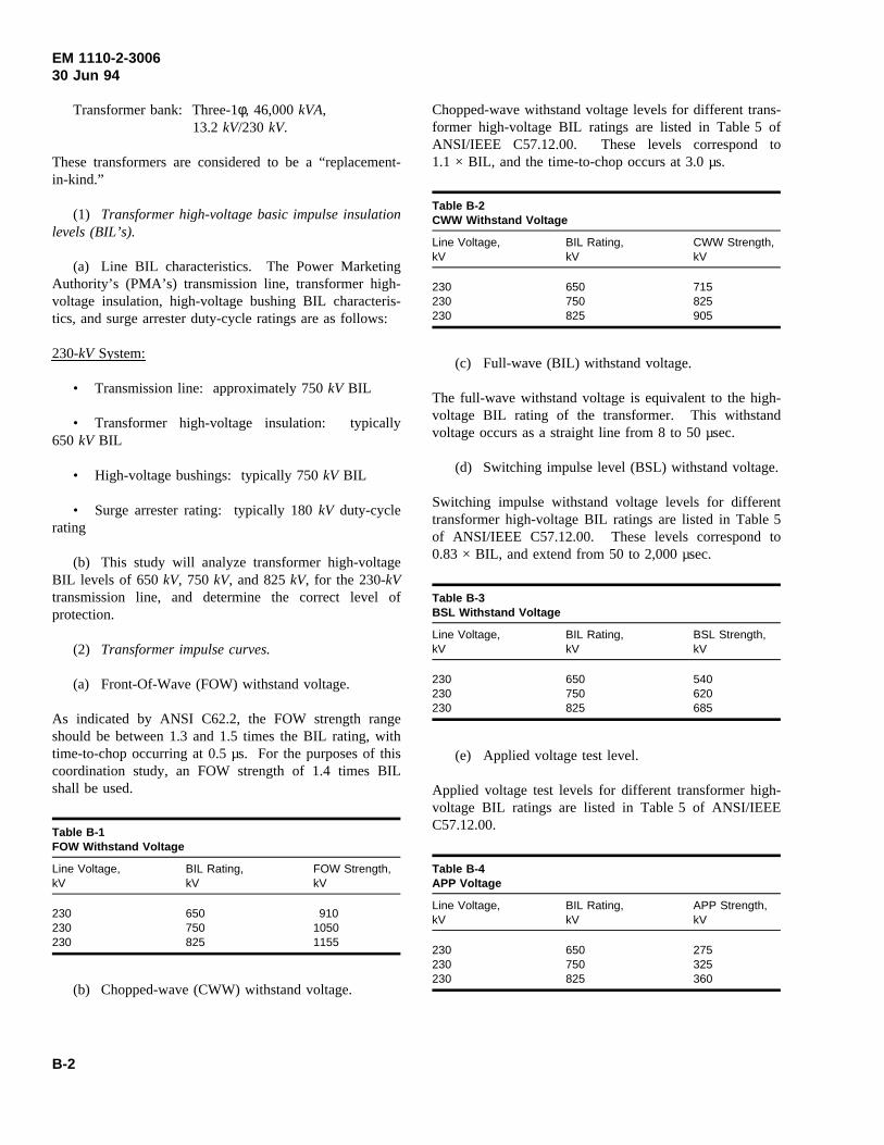
EM 1110-2-300630 Jun 94
Transformer bank: Three-1φ, 46,000kVA,13.2 kV/230 kV.
These transformers are considered to be a “replacement-in-kind.”
(1) Transformer high-voltage basic impulse insulationlevels (BIL’s).
(a) Line BIL characteristics. The Power MarketingAuthority’s (PMA’s) transmission line, transformer high-voltage insulation, high-voltage bushing BIL characteris-tics, and surge arrester duty-cycle ratings are as follows:
230-kV System:
• Transmission line: approximately 750kV BIL
• Transformer high-voltage insulation: typically650 kV BIL
• High-voltage bushings: typically 750kV BIL
• Surge arrester rating: typically 180kV duty-cyclerating
(b) This study will analyze transformer high-voltageBIL levels of 650kV, 750 kV, and 825kV, for the 230-kVtransmission line, and determine the correct level ofprotection.
(2) Transformer impulse curves.
(a) Front-Of-Wave (FOW) withstand voltage.
As indicated by ANSI C62.2, the FOW strength rangeshould be between 1.3 and 1.5 times the BIL rating, withtime-to-chop occurring at 0.5 µs. For the purposes of thiscoordination study, an FOW strength of 1.4 times BILshall be used.
Table B-1FOW Withstand Voltage
Line Voltage, BIL Rating, FOW Strength,kV kV kV
230 650 910230 750 1050230 825 1155
(b) Chopped-wave (CWW) withstand voltage.
Chopped-wave withstand voltage levels for different trans-former high-voltage BIL ratings are listed in Table 5 ofANSI/IEEE C57.12.00. These levels correspond to1.1 × BIL, and the time-to-chop occurs at 3.0 µs.
Table B-2CWW Withstand Voltage
Line Voltage, BIL Rating, CWW Strength,kV kV kV
230 650 715230 750 825230 825 905
(c) Full-wave (BIL) withstand voltage.
The full-wave withstand voltage is equivalent to the high-voltage BIL rating of the transformer. This withstandvoltage occurs as a straight line from 8 to 50 µsec.
(d) Switching impulse level (BSL) withstand voltage.
Switching impulse withstand voltage levels for differenttransformer high-voltage BIL ratings are listed in Table 5of ANSI/IEEE C57.12.00. These levels correspond to0.83 × BIL, and extend from 50 to 2,000 µsec.
Table B-3BSL Withstand Voltage
Line Voltage, BIL Rating, BSL Strength,kV kV kV
230 650 540230 750 620230 825 685
(e) Applied voltage test level.
Applied voltage test levels for different transformer high-voltage BIL ratings are listed in Table 5 of ANSI/IEEEC57.12.00.
Table B-4APP Voltage
Line Voltage, BIL Rating, APP Strength,kV kV kV
230 650 275230 750 325230 825 360
B-2
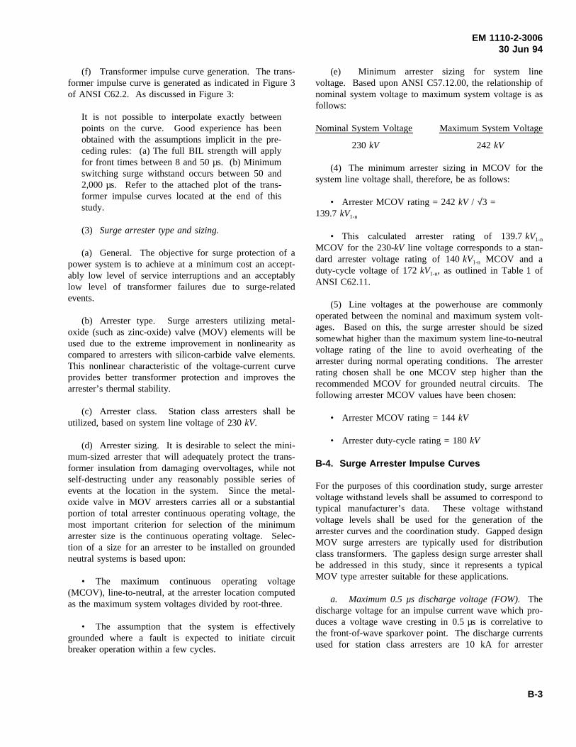
EM 1110-2-300630 Jun 94
(f) Transformer impulse curve generation. The trans-former impulse curve is generated as indicated in Figure 3of ANSI C62.2. As discussed in Figure 3:
It is not possible to interpolate exactly betweenpoints on the curve. Good experience has beenobtained with the assumptions implicit in the pre-ceding rules: (a) The full BIL strength will applyfor front times between 8 and 50 µs. (b) Minimumswitching surge withstand occurs between 50 and2,000 µs. Refer to the attached plot of the trans-former impulse curves located at the end of thisstudy.
(3) Surge arrester type and sizing.
(a) General. The objective for surge protection of apower system is to achieve at a minimum cost an accept-ably low level of service interruptions and an acceptablylow level of transformer failures due to surge-relatedevents.
(b) Arrester type. Surge arresters utilizing metal-oxide (such as zinc-oxide) valve (MOV) elements will beused due to the extreme improvement in nonlinearity ascompared to arresters with silicon-carbide valve elements.This nonlinear characteristic of the voltage-current curveprovides better transformer protection and improves thearrester’s thermal stability.
(c) Arrester class. Station class arresters shall beutilized, based on system line voltage of 230kV.
(d) Arrester sizing. It is desirable to select the mini-mum-sized arrester that will adequately protect the trans-former insulation from damaging overvoltages, while notself-destructing under any reasonably possible series ofevents at the location in the system. Since the metal-oxide valve in MOV arresters carries all or a substantialportion of total arrester continuous operating voltage, themost important criterion for selection of the minimumarrester size is the continuous operating voltage. Selec-tion of a size for an arrester to be installed on groundedneutral systems is based upon:
• The maximum continuous operating voltage(MCOV), line-to-neutral, at the arrester location computedas the maximum system voltages divided by root-three.
• The assumption that the system is effectivelygrounded where a fault is expected to initiate circuitbreaker operation within a few cycles.
(e) Minimum arrester sizing for system linevoltage. Based upon ANSI C57.12.00, the relationship ofnominal system voltage to maximum system voltage is asfollows:
Nominal System Voltage Maximum System Voltage
230 kV 242 kV
(4) The minimum arrester sizing in MCOV for thesystem line voltage shall, therefore, be as follows:
• Arrester MCOV rating = 242kV / √3 =139.7kV1-n
• This calculated arrester rating of 139.7kV1-n
MCOV for the 230-kV line voltage corresponds to a stan-dard arrester voltage rating of 140kV1-n MCOV and aduty-cycle voltage of 172kV1-n, as outlined in Table 1 ofANSI C62.11.
(5) Line voltages at the powerhouse are commonlyoperated between the nominal and maximum system volt-ages. Based on this, the surge arrester should be sizedsomewhat higher than the maximum system line-to-neutralvoltage rating of the line to avoid overheating of thearrester during normal operating conditions. The arresterrating chosen shall be one MCOV step higher than therecommended MCOV for grounded neutral circuits. Thefollowing arrester MCOV values have been chosen:
• Arrester MCOV rating = 144kV
• Arrester duty-cycle rating = 180kV
B-4. Surge Arrester Impulse Curves
For the purposes of this coordination study, surge arrestervoltage withstand levels shall be assumed to correspond totypical manufacturer’s data. These voltage withstandvoltage levels shall be used for the generation of thearrester curves and the coordination study. Gapped designMOV surge arresters are typically used for distributionclass transformers. The gapless design surge arrester shallbe addressed in this study, since it represents a typicalMOV type arrester suitable for these applications.
a. Maximum 0.5 µs discharge voltage (FOW).Thedischarge voltage for an impulse current wave which pro-duces a voltage wave cresting in 0.5 µs is correlative tothe front-of-wave sparkover point. The discharge currentsused for station class arresters are 10 kA for arrester
B-3
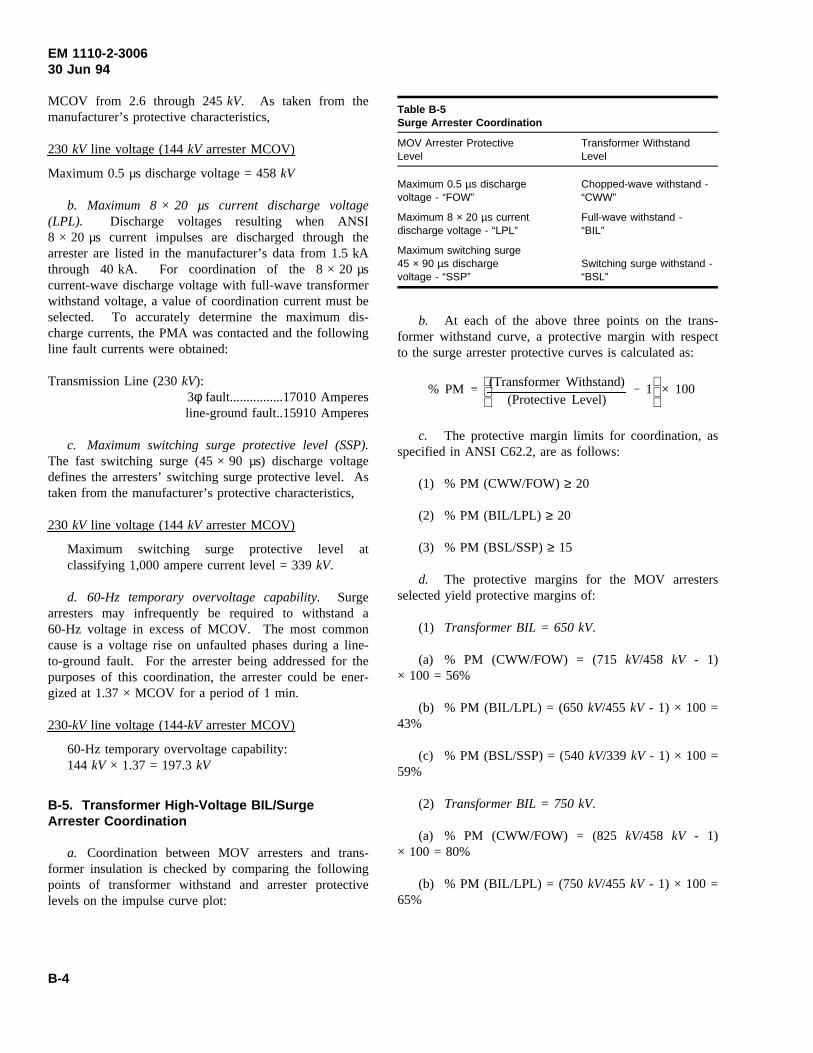
EM 1110-2-300630 Jun 94
MCOV from 2.6 through 245kV. As taken from themanufacturer’s protective characteristics,
230 kV line voltage (144kV arrester MCOV)
Maximum 0.5 µs discharge voltage = 458kV
b. Maximum 8 × 20 µs current discharge voltage(LPL). Discharge voltages resulting when ANSI8 × 20 µs current impulses are discharged through thearrester are listed in the manufacturer’s data from 1.5 kAthrough 40 kA. For coordination of the 8 × 20 µscurrent-wave discharge voltage with full-wave transformerwithstand voltage, a value of coordination current must beselected. To accurately determine the maximum dis-charge currents, the PMA was contacted and the followingline fault currents were obtained:
Transmission Line (230kV):3φ fault................17010 Amperesline-ground fault..15910 Amperes
c. Maximum switching surge protective level (SSP).The fast switching surge (45 × 90 µs) discharge voltagedefines the arresters’ switching surge protective level. Astaken from the manufacturer’s protective characteristics,
230 kV line voltage (144kV arrester MCOV)
Maximum switching surge protective level atclassifying 1,000 ampere current level = 339kV.
d. 60-Hz temporary overvoltage capability.Surgearresters may infrequently be required to withstand a60-Hz voltage in excess of MCOV. The most commoncause is a voltage rise on unfaulted phases during a line-to-ground fault. For the arrester being addressed for thepurposes of this coordination, the arrester could be ener-gized at 1.37 × MCOV for a period of 1 min.
230-kV line voltage (144-kV arrester MCOV)
60-Hz temporary overvoltage capability:144 kV × 1.37 = 197.3kV
B-5. Transformer High-Voltage BIL/SurgeArrester Coordination
a. Coordination between MOV arresters and trans-former insulation is checked by comparing the followingpoints of transformer withstand and arrester protectivelevels on the impulse curve plot:
Table B-5Surge Arrester Coordination
MOV Arrester Protective Transformer WithstandLevel Level
Maximum 0.5 µs discharge Chopped-wave withstand -voltage - “FOW” “CWW”
Maximum 8 × 20 µs current Full-wave withstand -discharge voltage - “LPL” “BIL”
Maximum switching surge45 × 90 µs discharge Switching surge withstand -voltage - “SSP” “BSL”
b. At each of the above three points on the trans-former withstand curve, a protective margin with respectto the surge arrester protective curves is calculated as:
% PM
(Transformer Withstand)(Protective Level)
1 × 100
c. The protective margin limits for coordination, asspecified in ANSI C62.2, are as follows:
(1) % PM (CWW/FOW)≥ 20
(2) % PM (BIL/LPL) ≥ 20
(3) % PM (BSL/SSP)≥ 15
d. The protective margins for the MOV arrestersselected yield protective margins of:
(1) Transformer BIL = 650 kV.
(a) % PM (CWW/FOW) = (715kV/458 kV - 1)× 100 = 56%
(b) % PM (BIL/LPL) = (650kV/455 kV - 1) × 100 =43%
(c) % PM (BSL/SSP) = (540kV/339 kV - 1) × 100 =59%
(2) Transformer BIL = 750 kV.
(a) % PM (CWW/FOW) = (825kV/458 kV - 1)× 100 = 80%
(b) % PM (BIL/LPL) = (750kV/455 kV - 1) × 100 =65%
B-4
EM 1110-2-300630 Jun 94
(c) % PM (BSL/SSP) = (620kV/339 kV - 1) × 100 =83%
(3) Transformer BIL = 825 kV.
(a) % PM (CWW/FOW) = (905kV/458 kV - 1)× 100 = 98%
(b) % PM (BIL/LPL) = (825kV/455 kV - 1) × 100 =81%
(c) % PM (BSL/SSP) = (685kV/339 kV - 1) × 100 =102%
d. Summary.
(1) As noted from the transformer BIL / surgearrester coordination plots (Figure B-1), the minimumprotective margins are much greater than the designstandards, due to the better protective characteristics ofMOV surge arresters.
(2) A high-voltage winding BIL rating of 750kV BILfor the 230-kV nominal system voltage shall be selectedfor the transformers. These BIL selections will providethe following advantages: (a) reduction in transformerprocurement costs, (b) reduction in transformer losses,(c) better coordination with the BIL rating structure of thesystem, and (d) reduction in the physical size of the trans-former. Item (d) is due consideration because of vaultsize limitations.
B-6. Sample Study B2, Transformer BushingsRating
a. Objective. The objective of this study is to deter-mine the proper ratings for the bushings and bushingcurrent transformers on the replacement generator step-up(GSU) transformers.
b. References.The following references were usedin the performance of this study. Complete citations canbe found in Appendix A of this document, “References.”
(1) ANSI C76.1-1976 / IEEE Std. 21-1976.
(2) ANSI C76.2-1977 / IEEE Std. 24-1977.
(3) ANSI C57.13-1978.
(4) Main Unit Generator Step-up TransformerReplacement, TransformerkVA Rating Study.
(5) Main Unit Generator Step-up TransformerReplacement, BIL / Surge Arrester Coordination Study.
c. Procedure. As summarized in the referencedstudies, the transformers shall be rated as follows:
46,000kVA13.2 kV /230 kV Y750 kV High-Voltage Winding BIL110 kV Low-Voltage Winding BIL
d. Bushing ratings and characteristics.As outlinedin IEEE Std. 21-1976, performance characteristics basedupon definite conditions shall include the following:
• Rated maximum line-to-ground voltage
• Rated frequency
• Rated dielectric strengths
• Rated continuous currents
The bushings will not be subject to any unusual serviceconditions.
(1) Rated maximum line-to-ground voltage.
(a) Based upon ANSI C57.12.00, the relationship ofnominal system voltage to maximum system voltage is asfollows:
Nominal System Voltage Maximum System Voltage
230 kV 242 kV
(b) The maximum line-to-ground voltage is therefore:
MaximumMaximum System Voltage Line-To-Ground Voltage
242 kV 139.7kV
(c) Line voltages are commonly operated betweenthe nominal and maximum system voltages. Based onthis, the selection of maximum line-to-ground voltageswill be chosen as 5 percent higher than the ANSI sug-gested values to avoid overheating of the bushings duringnormal operating conditions. This leads to bushing selec-tions with the following Rated Maximum Line-To-GroundVoltage, Insulation Class, and BIL characteristics:
B-5
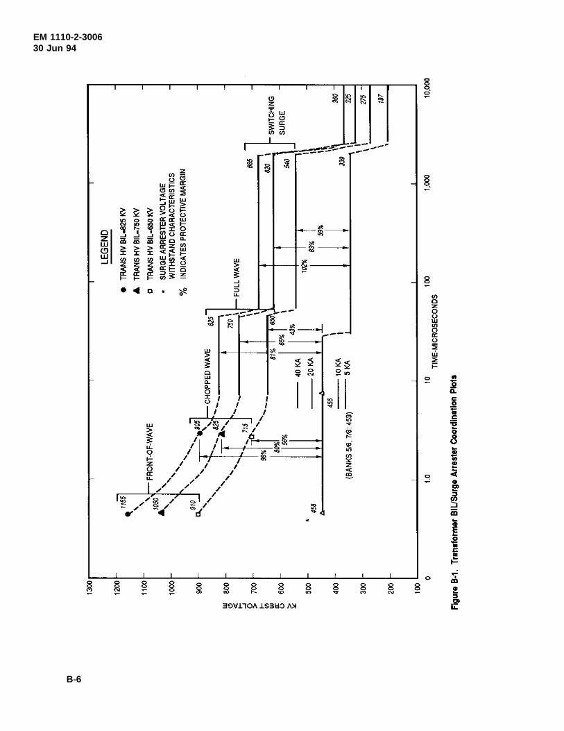
EM 1110-2-300630 Jun 94
B-6
EM 1110-2-300630 Jun 94
• Line Voltage: 230kV
• Bushing Insulation Class: 196kV
• Bushing BIL: 900kV
• Rated Maximum Line-to-Ground Voltage: 146kV
(d) The low-voltage terminal bushings shall be insu-lated at the same BIL as the generator windings, i.e.,110 kV BIL. This corresponds to an insulation class of15 kV.
(e) The neutral terminal bushings shall be insulated at150 kV BIL, corresponding to an insulation class of25 kV.
(2) Rated frequency. The frequency at which thebushings shall be designed to operate is 60 Hz.
(3) Rated dielectric strengths. The rated dielectricstrengths for the transformer bushings, expressed in termsof specific values of voltage withstand tests, shall be asfollows:
(a) 230kV system high-voltage bushings.
• 60 Hz, 1-min Dry Voltage Withstand Test:425 kV rms
• 60 Hz, 10-sec Wet Voltage Withstand Test:350 kV rms
• Full Wave Impulse Voltage Withstand Test:900 kV
• Chopped Wave Impulse -kV Crest, 2µsecWithstand: 1160kV
• Chopped Wave Impulse -kV Crest, 3µsecWithstand: 1040kV
(b) 13.2kV low-voltage bushings.
• 60 Hz, 1-min Dry Voltage Withstand Test:50 kV rms
• 60 Hz, 10-sec Wet Voltage Withstand Test:45 kV rms
• Full Wave Impulse Voltage Withstand Test:110 kV
• Chopped Wave Impulse -kV Crest, 2µsecWithstand: 142kV
• Chopped Wave Impulse -kV Crest, 3µsecWithstand: 126kV
(c) Neutral bushings.
• 60 Hz, 1-min Dry Voltage Withstand Test:60 kV rms
• 60 Hz, 10-sec Wet Voltage Withstand Test:50 kV rms
• Full Wave Impulse Voltage Withstand Test:150 kV
• Chopped Wave Impulse -kV Crest, 2µsecWithstand: 194kV
• Chopped Wave Impulse -kV Crest, 3µsecWithstand: 172kV
(4) Rated continuous currents.
(a) The following are the rated currents for the trans-former bank, based upon the maximumkVA generatingcapacity of each generating unit:
• Two generators shall be connected to the trans-former bank. The maximumkVA rating of each genera-tor is 69,000kVA. The total of the generator ratedcurrents for these units is, therefore:
I2S3φ
3 VL
(2)69,000kVA
3 (13.8kV)5,774 Amps
• Total rated low-voltage terminal current for deltaconnected transformers:
• Rated line current:
II
3
5,774 Amps
33,334 Amps
IL 5,774 Amps× 13.2kV230kV
331 Amps
(b) Based on the above data, the suggested minimumbushing rated current requirements shall be as follows:
B-7
EM 1110-2-300630 Jun 94
• High-Voltage Bushing Minimum Current Rating:400 Amperes
• Neutral Bushing Minimum Current Rating:400 Amperes
• Low-Voltage Bushing Minimum Current Rating:3,500 Amperes
e. Bushing current transformer (CT) ratings andcharacteristics. Two standard multi-ratio bushing-typeCT’s for relaying service shall be installed in each of the230-kV transformer high-voltage bushings for the bank,conforming to accuracy classification ’C’, rated 400/5.These CT’s shall be used for transformer differentialrelaying and line protective relaying.
B-7. Sample Study B3, Transformer Efficiency
a. Objective. The objective of this study is to esti-mate the transformer efficiencies for the proposed replace-ment generator step-up (GSU) transformers.
b. References.The following references were usedin the performance of this study. Complete citations canbe found in Appendix A of this document, “References.”
(1) Main Unit Generator Step-up TransformerReplacement, TransformerkVA Rating Study.
(2) Main Unit Generator Step-up TransformerReplacement, BIL/Surge Arrester Coordination Study.
(3) Westinghouse Electric Corporation. 1964 (locatedat end of study).
c. Procedure. The calculations for estimating thetransformer losses and efficiency calculations shall bebased on the Westinghouse Technical Data BulletinNo. 48-500. The following steps will be used in deter-mining this data:
(1) Determine the insulation level of the transformer.
(2) Determine the equivalent two winding 65 °Creference product factors.
(3) Determine the basic product factor from theTable A: 65 °C reference product factors.
(4) Adjust for special features.
(5) Determine the ratio of losses.
(6) Determine the losses.
(7) Determine transformer estimated efficiency.
d. Transformer bank: 46,000 kVA, 1φ, 13.2kV/230 kV Y, FOA cooled transformers.
(1) Transformer BIL rating.
(a) Low-voltage windings: 110kV BIL.
(b) High-voltage windings: 750kV BIL.
(2) Equivalent two-winding 65 °C self-cooled MVA.For FOA type cooling rated at 65 °C, the specifiedMVAis for self-cooling.
(3) Basic product factor determination (Pe). Basicreference product factor:
(a) As taken from Table A, A = .0001590, B = .2564
Pe A MVAB
MVA
(b) Conversion of the MVA(1φ) to MVA(3φ) isrequired to calculate the product factor.
MVA(3φ) = 2 × MVA(1φ) = 2 × 46MVA = 92 MVA
(c) Therefore, the base product factor (Pe) is:
Pe .000159092 .2564
92.028257
(4) Adjust Pe for % adders (Pr). The base productfactor calculated in (c) should be adjusted further forspecial features. The adjusted base product factor,Pr, iscalculated as follows:
Pr (1 PercentAdditions100
) × Pe
(a) From Table B, on page 12 of the Westinghousedocument, the percent additions are:
Front of Wave Impulse Test: 5%
(b) Final adjusted base product factor:
Pr = .028257 × (1+.05) = .029669
B-8
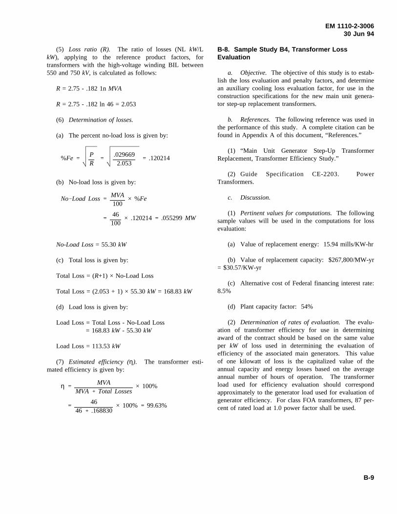
EM 1110-2-300630 Jun 94
(5) Loss ratio (R). The ratio of losses (NLkW/LkW), applying to the reference product factors, fortransformers with the high-voltage winding BIL between550 and 750kV, is calculated as follows:
R = 2.75 - .182 1nMVA
R = 2.75 - .182 ln 46 = 2.053
(6) Determination of losses.
(a) The percent no-load loss is given by:
(b) No-load loss is given by:
%FePR
.0296692.053
.120214
No-Load Loss= 55.30kW
No Load LossMVA100
× %Fe
46100
× .120214 .055299MW
(c) Total loss is given by:
Total Loss = (R+1) × No-Load Loss
Total Loss = (2.053 + 1) × 55.30kW = 168.83kW
(d) Load loss is given by:
Load Loss = Total Loss - No-Load Loss= 168.83kW - 55.30kW
Load Loss = 113.53kW
(7) Estimated efficiency (η). The transformer esti-mated efficiency is given by:
η MVAMVA Total Losses
× 100%
4646 .168830
× 100% 99.63%
B-8. Sample Study B4, Transformer LossEvaluation
a. Objective. The objective of this study is to estab-lish the loss evaluation and penalty factors, and determinean auxiliary cooling loss evaluation factor, for use in theconstruction specifications for the new main unit genera-tor step-up replacement transformers.
b. References.The following reference was used inthe performance of this study. A complete citation can befound in Appendix A of this document, “References.”
(1) “Main Unit Generator Step-Up TransformerReplacement, Transformer Efficiency Study.”
(2) Guide Specification CE-2203. PowerTransformers.
c. Discussion.
(1) Pertinent values for computations.The followingsample values will be used in the computations for lossevaluation:
(a) Value of replacement energy: 15.94 mills/KW-hr
(b) Value of replacement capacity: $267,800/MW-yr= $30.57/KW-yr
(c) Alternative cost of Federal financing interest rate:8.5%
(d) Plant capacity factor: 54%
(2) Determination of rates of evaluation.The evalu-ation of transformer efficiency for use in determiningaward of the contract should be based on the same valueper kW of loss used in determining the evaluation ofefficiency of the associated main generators. This valueof one kilowatt of loss is the capitalized value of theannual capacity and energy losses based on the averageannual number of hours of operation. The transformerload used for efficiency evaluation should correspondapproximately to the generator load used for evaluation ofgenerator efficiency. For class FOA transformers, 87 per-cent of rated load at 1.0 power factor shall be used.
B-9
EM 1110-2-300630 Jun 94
B-10
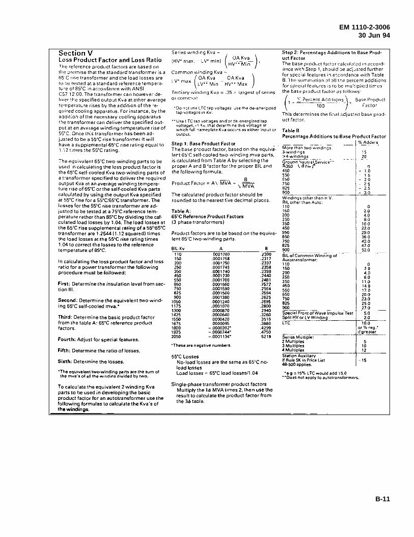
EM 1110-2-300630 Jun 94
B-11
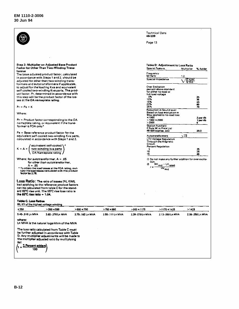
EM 1110-2-300630 Jun 94
B-12
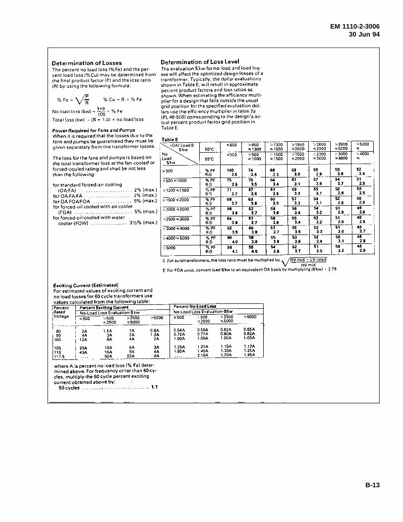
EM 1110-2-300630 Jun 94
B-13
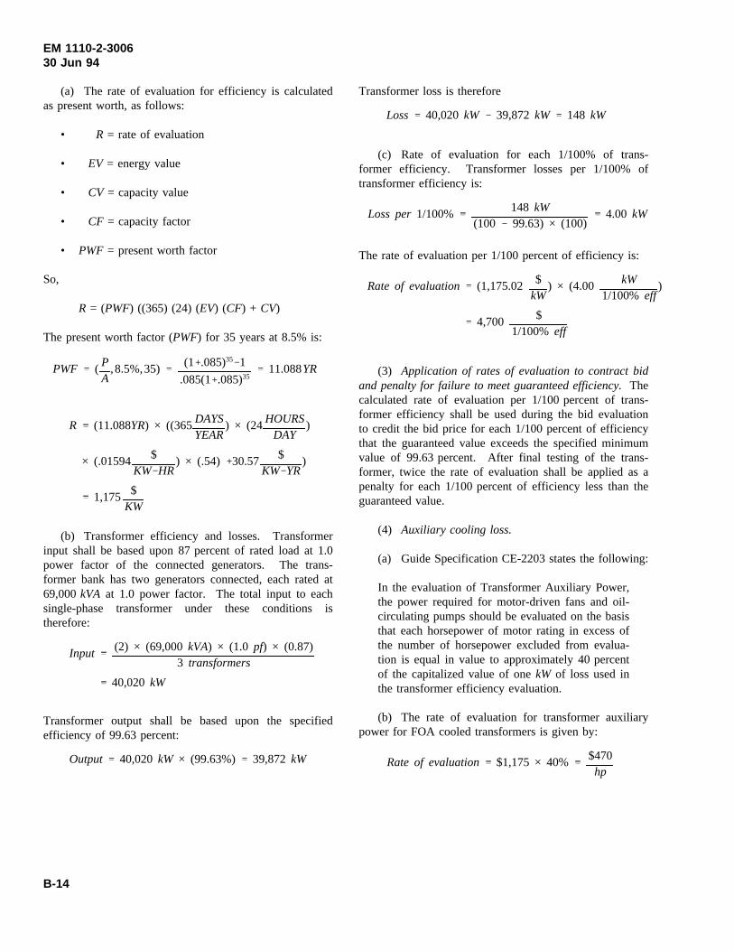
EM 1110-2-300630 Jun 94
(a) The rate of evaluation for efficiency is calculatedas present worth, as follows:
• R = rate of evaluation
• EV = energy value
• CV = capacity value
• CF = capacity factor
• PWF = present worth factor
So,
R = (PWF) ((365) (24) (EV) (CF) + CV)
The present worth factor (PWF) for 35 years at 8.5% is:
PWF ( PA
,8.5%,35) (1 .085)35 1
.085(1 .085)3511.088YR
R (11.088YR) × ((365DAYSYEAR
) × (24HOURSDAY
)
× (.01594 $KW HR
) × (.54) 30.57 $KW YR
)
1,175 $KW
(b) Transformer efficiency and losses. Transformerinput shall be based upon 87 percent of rated load at 1.0power factor of the connected generators. The trans-former bank has two generators connected, each rated at69,000kVA at 1.0 power factor. The total input to eachsingle-phase transformer under these conditions istherefore:
Input(2) × (69,000kVA) × (1.0 pf) × (0.87)
3 transformers
40,020kW
Transformer output shall be based upon the specifiedefficiency of 99.63 percent:
Output 40,020kW × (99.63%) 39,872kW
Transformer loss is therefore
Loss 40,020kW 39,872kW 148 kW
(c) Rate of evaluation for each 1/100% of trans-former efficiency. Transformer losses per 1/100% oftransformer efficiency is:
The rate of evaluation per 1/100 percent of efficiency is:
Loss per1/100% 148 kW(100 99.63) × (100)
4.00 kW
(3) Application of rates of evaluation to contract bid
Rate of evaluation (1,175.02 $kW
) × (4.00 kW1/100% eff
)
4,700 $1/100% eff
and penalty for failure to meet guaranteed efficiency.Thecalculated rate of evaluation per 1/100 percent of trans-former efficiency shall be used during the bid evaluationto credit the bid price for each 1/100 percent of efficiencythat the guaranteed value exceeds the specified minimumvalue of 99.63 percent. After final testing of the trans-former, twice the rate of evaluation shall be applied as apenalty for each 1/100 percent of efficiency less than theguaranteed value.
(4) Auxiliary cooling loss.
(a) Guide Specification CE-2203 states the following:
In the evaluation of Transformer Auxiliary Power,the power required for motor-driven fans and oil-circulating pumps should be evaluated on the basisthat each horsepower of motor rating in excess ofthe number of horsepower excluded from evalua-tion is equal in value to approximately 40 percentof the capitalized value of onekW of loss used inthe transformer efficiency evaluation.
(b) The rate of evaluation for transformer auxiliarypower for FOA cooled transformers is given by:
Rate of evaluation $1,175 × 40% $470hp
B-14

EM 1110-2-300630 Jun 94
(c) The total horsepower of motor-driven fans and oilpumps excluded from evaluation for each size of trans-former is given by:
Total losses based on 99.6% estimated efficiency:
Total auxiliary loss inhp excluded from evaluation:
46,000kVA99.6%
46,000kVA 184.74kW
184.74kW × .05 hpkW
9.24 hp
B-15