Embed Size (px)
Citation preview
USER MANUAL COFFEE MACHINE VITRO “S-1”
MANUAL REFERENCIA: 81044 307 ; EDICIÓN 01-20 91
User Manual VITRO S1
- 2 -
AZKOYEN S.A. Azkoyen Andina S.A.S. Av. San Silvestre S/N Vía Virginia 31350 PERALTA Corregimiento Caimalito, Bodega B-16 Navarra, ESPAÑA Zona Franca Internacional 660007 – Pereira, COLOMBIA
User Manual VITRO S1
- 3 -
WARNINGS ............................................................................................................................... 4 UE Declaration of Conformity ................................................................................................. 6 CHAPTER 1. GENERAL CHARACTERISTICS ........................................................................ 7
1.1.- Description of the machine. ........................................................................................... 7 1.2.- Description of the main components .............................................................................. 8
CHAPTER 2. INSTALLATION AND STARTING-UP ................................................................ 9 2.1.- Choice of location for the machine ................................................................................. 9 2.2.- Electrical installation ...................................................................................................... 9 2.3.- Start-up .......................................................................................................................... 9 2.4.- Water supply .................................................................................................................. 9 2.5.- Payment module .......................................................................................................... 10
CHAPTER 3. DESCRIPTION OF THE MACHINE .................................................................. 11 3.1.- Soluble product hoppers .............................................................................................. 11 3.2.- Initial loading of soluble product. .................................................................................. 11 3.3.- Loading coffee beans ................................................................................................... 11 3.4.- Initial loading of water .................................................................................................. 11 3.5.- Programming the water temperature under special conditions .................................... 12 3.6.- Bean coffee group (Espresso Machines) ..................................................................... 12 3.7.- Dismantling the coffee bean group .............................................................................. 13 3.8.- Settings and adjustments ............................................................................................. 13
CHAPTER 4. PROGRAMMING .............................................................................................. 15 4.1.- How do we communicate with the machine? ............................................................... 15 4.2.- What can be programmed? ......................................................................................... 15 4.3.- Programming menu .................................................................................................... 15 4.4.- List of functions ............................................................................................................ 16 4.5.- Customising the Programming Menu ........................................................................... 18 4.6.- Service programming. .................................................................................................. 18
CHAPTER 5 – TROUBLESHOOTING AND MAINTENANCE ................................................ 21 5.1 - Reset ........................................................................................................................... 21 5.2.- Error detected by the machine. .................................................................................... 21 5.3.- Changing the product labels ........................................................................................ 22
CHAPTER 6. CLEANING THE MACHINE. ............................................................................ 23 6.1.- Components that require regular cleaning ................................................................... 23 6.2.- Regular cleaning of the machine and maintenance operations ................................... 24 6.3.- Cleaning cycle for the group brewing chamber ............................................................ 24 6.4.- Descaling cycle. ........................................................................................................... 26 6.5.- Replacing the water filter ............................................................................................. 27 6.6.- Exterior cleaning .......................................................................................................... 27
Anexe 1. THE TREATMENT, COLLECTION, RECYCLING AND DISPOSAL OF THIS DEVICE ................................................................................................................................... 28
User Manual VITRO S1
- 4 -
WARNINGS
General BEFORE USING THIS DISPENSER, THIS MANUAL MUST BE READ CAREFULLY This automatic dispenser has been designed and built in accordance with all safety legislation in
force.
Installation THE INSTALLATION AND OPERATIONS REQUIRED FOR INITIAL START-UP OF THESE MACHINES
MUST BE PERFORMED BY QUALIFIED PERSONNEL. The plug of the machine has an earth connection. The outlet must be connected to a good earth
connection and must be located in an accessible position once the machine is installed. Ensure that the electrical installation, the outlet and the automatic circuit breaker have the
appropriate sizes for machine consumption. These machines are designed EXCLUSIVELY FOR INDOOR USE. They must not be installed in
places that may be exposed to sprayed water, and they likewise must not be cleaned using sprayed water.
Safety The machine should be installed in locations that meet the recommendations of temperature,
electrical and water installations, weights, etc., in this manual and performed by qualified personnel.
THE MACHINE HAS COMPONENTS THAT OPERATE AT DANGEROUS VOLTAGES. DO NOT DISCONNECT ANY COMPONENT. ONLY TECHNICAL SERVICE IS AUTHORISED. THE FEEDER CABLE CAN ONLY BE REPLACED BY AUTHORISED TECHNICAL PERSONNEL.
This appliance is not designed to be used by persons (including children) with reduced physical, sensory or mental capabilities, lack of experience or knowledge, unless they are supervised or have been instructed in its use by somebody responsible for their safety. Children should be supervised to ensure that they do not play with the appliance. Section 7.12 of EN60335.
This appliance is not designed to be used by persons (including children aged 8 and above) with reduced physical, sensory or mental capabilities, lack of experience or knowledge, unless they are supervised or have been instructed in its use by somebody responsible for their safety.
In any case, this appliance cannot be cleaned and serviced by unsupervised children. AZKOYEN hereby declines all liability for damages caused to persons or things as a result of the
following: o Incorrect installation. o Inadequate electrical and/or hydraulic installation. o Deficient cleaning or maintenance. o Incorrect use of the machine. o Using non-original replacement parts or making unauthorised modifications
User Manual VITRO S1
- 5 -
If it is necessary to move the machine avoid: o Tipping the machine o Dragging or lifting it with some kind of pulling system (rope, straps, etc.). o Shaking or striking the machine, no matter whether it is in protective wrapping or not.
All elements that require tools to be disassembled must only be handled by qualified technical personnel.
Mantenaince Given the characteristics of some food products, these may lead to incorrect operation of the
machine if used beyond the parameters of temperature and relative humidity recommended in this manual.
Water must be prevented from freezing in the interior of the machine. If any maintenance task is going to performed and the machine is going to be disconnected for a long period of time, the boiler must be emptied.
The user or person responsible for refilling and cleaning the device must follow the instructions set forth in this manual.
For refilling, only use food products prepared specifically for these kinds of vending machines. Do not touch the product with your hands, and prevent liquids from falling inside the product hoppers.
User manual This manual is an integral part of the machine, and as such, it must always remain inside the same
so that it may be consulted at any time. This document contains private property information protected by legislation on intellectual
property. All rights are hereby reserved. No part of this document may be photocopied, reproduced or translated without the prior written consent of AZKOYEN.
AZKOYEN hereby reserves the right to introduce, without prior notice, all improvements to this model derived from its constant research.
REMEMBER: To get the most out of your machine, follow the instructions in this manual.
FOR ANY ADDITIONAL INFORMATION THAT IS NOT SPECIFIED HEREIN CONTACT YOUR DISTRIBUTOR OR ACCESS THE TECHNICAL MANUAL FROM AZKOYEN'S OFFICIAL WEBPAGE
User Manual VITRO S1
- 6 -
UE Declaration of Conformity We, the manufacturer, Azkoyen Vending Systems, declare under our sole responsibility that our product is in compliance with the essential requirements of the following European Union issued Directives:
EMC Directive 2014/30/UE, and his modifications Low Voltage Directive 2014/35/UE, and his modifications RoHS Directive 2015/863/UE Regulation 1935/2004, on materials and articles intended to come into contact with food
The product is according with the following norms / standards:
UNE-EN 60335-2-75:05 +A1:2005+A11:2006 + A2:2008+A12:2010 UNE-EN 60335-1:2012+AC: 2014+A11:2014 UNE-EN 55014-1:08 + A1:09+A2:2012 UNE-EN 55014-2:2015 UNE-EN 61000-3-2:2014 UNE-EN 61000-3-3:2013
Azkoyen Vending Systems Avda. San Silvestre, s/n 31350 – peralta. SPAIN
User Manual VITRO S1
- 7 -
CHAPTER 1. GENERAL CHARACTERISTICS
1.1.- Description of the machine.
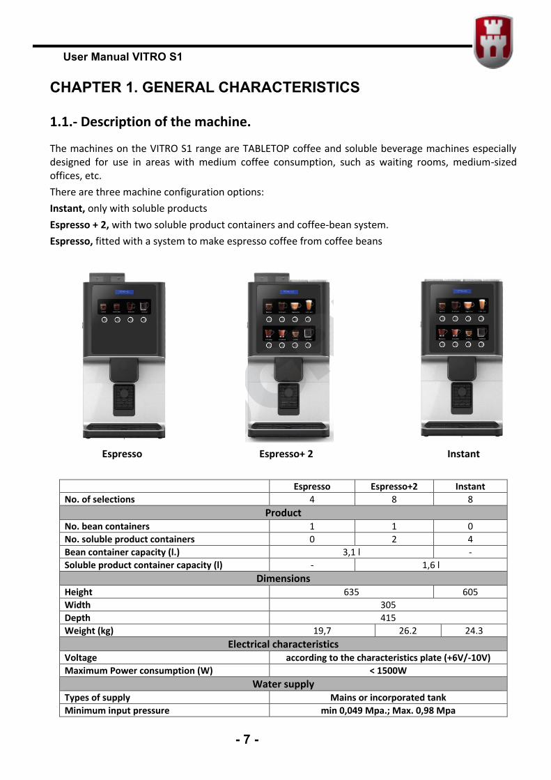
The machines on the VITRO S1 range are TABLETOP coffee and soluble beverage machines especially designed for use in areas with medium coffee consumption, such as waiting rooms, medium-sized offices, etc. There are three machine configuration options: Instant, only with soluble products Espresso + 2, with two soluble product containers and coffee-bean system. Espresso, fitted with a system to make espresso coffee from coffee beans Espresso Espresso+ 2 Instant
Espresso Espresso+2 Instant No. of selections 4 8 8
Product No. bean containers 1 1 0 No. soluble product containers 0 2 4 Bean container capacity (l.) 3,1 l - Soluble product container capacity (l) - 1,6 l
Dimensions Height 635 605 Width 305 Depth 415 Weight (kg) 19,7 26.2 24.3
Electrical characteristics Voltage according to the characteristics plate (+6V/-10V) Maximum Power consumption (W) < 1500W
Water supply Types of supply Mains or incorporated tank Minimum input pressure min 0,049 Mpa.; Max. 0,98 Mpa
User Manual VITRO S1
- 8 -
Diameter of the stopcock (to connect the mains hose)
¾” M
Water tank capacity (l) 4 Other Characteristics
Maximum work gradient 2º (on any axis) Sound level <80 dB(A) Optimum exterior environment temperature > 1ºC - <40ºC; <65% Rel. hum.
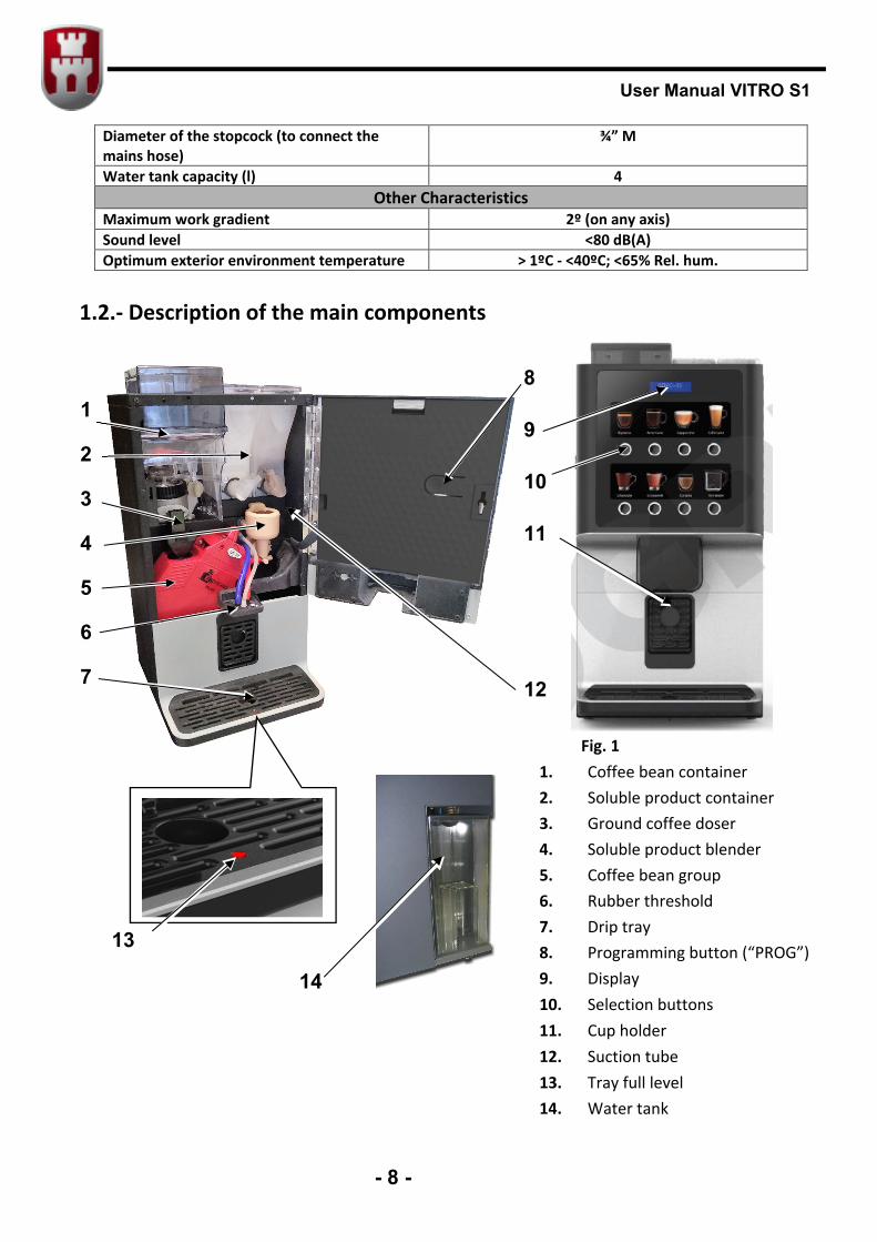
1.2.- Description of the main components
Fig. 1 1. Coffee bean container 2. Soluble product container 3. Ground coffee doser 4. Soluble product blender 5. Coffee bean group 6. Rubber threshold 7. Drip tray 8. Programming button (“PROG”) 9. Display 10. Selection buttons 11. Cup holder 12. Suction tube 13. Tray full level 14. Water tank
1
2
3
4
5
6
7
8
9
10
11
12
14
13
User Manual VITRO S1
- 9 -
CHAPTER 2. INSTALLATION AND STARTING-UP
2.1.- Choice of location for the machine
The machine must be placed on a unit or support so that it is stable and cannot be accidentally knocked over. The support must be well secured to the wall.
THE INSTALLATION OPERATIONS REQUIRED FOR THE INITIAL START-UP OF THESE MACHINES MUST BE PERFORMED BY QUALIFIED TECHNICAL STAFF.
2.2.- Electrical installation
The voltage of the electrical system must comply with the voltage indicated on the characteristics plate on the back of the machine and must not exceed the limits set in the country of use. Maximum power consumption is indicated on the machine characteristics plate.
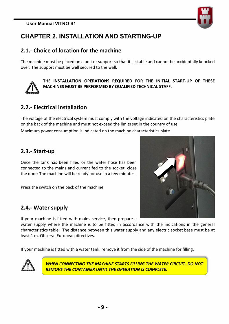
2.3.- Start-up
Once the tank has been filled or the water hose has been connected to the mains and current fed to the socket, close the door: The machine will be ready for use in a few minutes. Press the switch on the back of the machine.
2.4.- Water supply
If your machine is fitted with mains service, then prepare a water supply where the machine is to be fitted in accordance with the indications in the general characteristics table. The distance between this water supply and any electric socket base must be at least 1 m. Observe European directives. If your machine is fitted with a water tank, remove it from the side of the machine for filling.
WHEN CONNECTING THE MACHINE STARTS FILLING THE WATER CIRCUIT. DO NOT REMOVE THE CONTAINER UNTIL THE OPERATION IS COMPLETE.
User Manual VITRO S1
- 10 -
2.5.- Payment module
The machine can feature an optional payment module, which supports connection of a validator with MDB protocol. The installation instructions are included in the corresponding kit.
THE MACHINE CAN ONLY BE POWERED WITH 24DC (NOT WITH 24VAC).
User Manual VITRO S1
- 11 -
CHAPTER 3. DESCRIPTION OF THE MACHINE
3.1.- Soluble product hoppers
The Instant and Espresso+2 machines have 2 or more soluble product containers. These containers extract the product via a spindle to the Blender, where it is mixed with water sent from the boiler. Each hopper must always be loaded with the same type of product because the serving configuration activates the hopper programmed for each case. e.g. do not load the coffee hopper with a different product because the machine will use it for servings programmed with coffee.
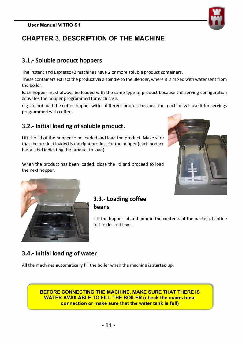
3.2.- Initial loading of soluble product.
Lift the lid of the hopper to be loaded and load the product. Make sure that the product loaded is the right product for the hopper (each hopper has a label indicating the product to load). When the product has been loaded, close the lid and proceed to load the next hopper.
3.3.- Loading coffee beans
Lift the hopper lid and pour in the contents of the packet of coffee to the desired level.
3.4.- Initial loading of water
All the machines automatically fill the boiler when the machine is started up.
BEFORE CONNECTING THE MACHINE, MAKE SURE THAT THERE IS
WATER AVAILABLE TO FILL THE BOILER (check the mains hose connection or make sure that the water tank is full)
User Manual VITRO S1
- 12 -
3.5.- Programming the water temperature under special conditions
The machine is programmed at the factory with an 85ºC boiler temperature by default. The water boiling point can be much less than 100ºC in some cities, according to their altitude. Malfunction of the hydraulic system of the unit can be caused if the temperature of the machine is modified to higher water boiling temperatures. Examples:
Altitude (over sea level)
Temp. Water boiling Temp. Max. recommended of the boiler (Function 461)
1500m 95ºC 92ºC 1800m 94ºC 91ºC 2100m 93ºC 90ºC 2400m 92ºC 89ºC 2700m 91ºC 88ºC
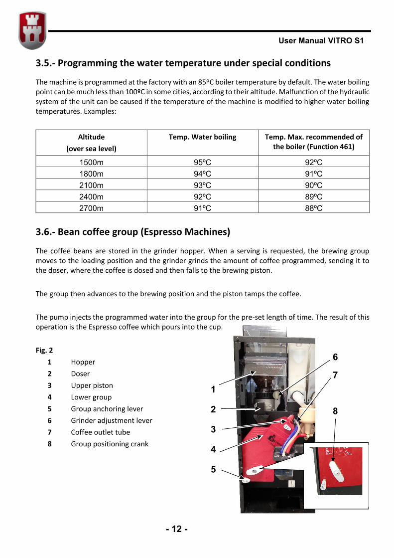
3.6.- Bean coffee group (Espresso Machines)
The coffee beans are stored in the grinder hopper. When a serving is requested, the brewing group moves to the loading position and the grinder grinds the amount of coffee programmed, sending it to the doser, where the coffee is dosed and then falls to the brewing piston. The group then advances to the brewing position and the piston tamps the coffee. The pump injects the programmed water into the group for the pre-set length of time. The result of this operation is the Espresso coffee which pours into the cup. Fig. 2
1 Hopper 2 Doser 3 Upper piston 4 Lower group 5 Group anchoring lever 6 Grinder adjustment lever 7 Coffee outlet tube 8 Group positioning crank
1
2
3
4
5
6
7
8
User Manual VITRO S1
- 13 -
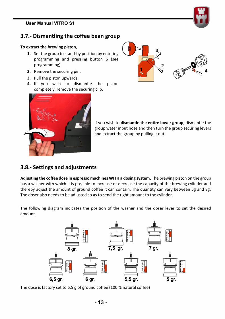
3.7.- Dismantling the coffee bean group
To extract the brewing piston, 1. Set the group to stand-by position by entering
programming and pressing button 6 (see programming).
2. Remove the securing pin. 3. Pull the piston upwards. 4. If you wish to dismantle the piston
completely, remove the securing clip. If you wish to dismantle the entire lower group, dismantle the group water input hose and then turn the group securing levers and extract the group by pulling it out.
3.8.- Settings and adjustments
Adjusting the coffee dose in espresso machines WITH a dosing system. The brewing piston on the group has a washer with which it is possible to increase or decrease the capacity of the brewing cylinder and thereby adjust the amount of ground coffee it can contain. The quantity can vary between 5g and 8g. The doser also needs to be adjusted so as to send the right amount to the cylinder. The following diagram indicates the position of the washer and the doser lever to set the desired amount.
The dose is factory set to 6.5 g of ground coffee (100 % natural coffee)
User Manual VITRO S1
- 14 -
Adjusting the coffee dose in espresso machines WITHOUT a dosing system. The grinder must be calibrated in machines without a dosing system using function F030. After it has been calibrated, the grinder will adjust the coffee dose after each service, as programmed with function 315. For example: every 2.45 seconds of operation of the grinder will produce an amount equivalent to 7 g. IMPORTANT: The washer position must be adjusted as indicated in the above diagram. If not, the unit might malfunction and faults might even be caused. Calibrating the grinder.
1 Remove the coffee grinder unit, as described in point 3.7. 2 Access the programming menu (see Chap. 4) and select function F030. Press the A and B
buttons until the display shows “GRINDER”. Next, press the D button. 3 The machine will grind and extract coffee during 10 seconds. Place a container at the grinder
outlet to collect the ground coffee. 4 Weigh the extracted product and enter the value using buttons A and B. Validate using button
D. The machine will now indicate the weight of the product in grams. Coffee grinding point adjustment. The grinder leaves the factory set to the optimum grinding position. If you want to grind the coffee finer, then you can move the adjustment lever one or two positions (with the motor running to prevent the teeth from jamming with coffee). The grinder adjustment lever is at the top of the group. Use it to set the ground coffee grade you wish to use. A “good coffee” is one which has been brewed at 9 kg/cm2, which is equivalent to a brewing time of between 15 and 20 sec.
User Manual VITRO S1
- 15 -
CHAPTER 4. PROGRAMMING
4.1.- How do we communicate with the machine?
VITRO S1 machine uses a selection keypad to communicate with the machine user. When the machine is in programming status, the programmable functions are accessed by pressing the different buttons. The machine has an information screen which shows messages during service, programming and warning messages for maintenance and cleaning.
4.2.- What can be programmed?
To access the programming screen, press the “PROG” button on the inside of the door (Fig. 1). The PROG button can also be used to exit the programming mode.
4.3.- Programming menu
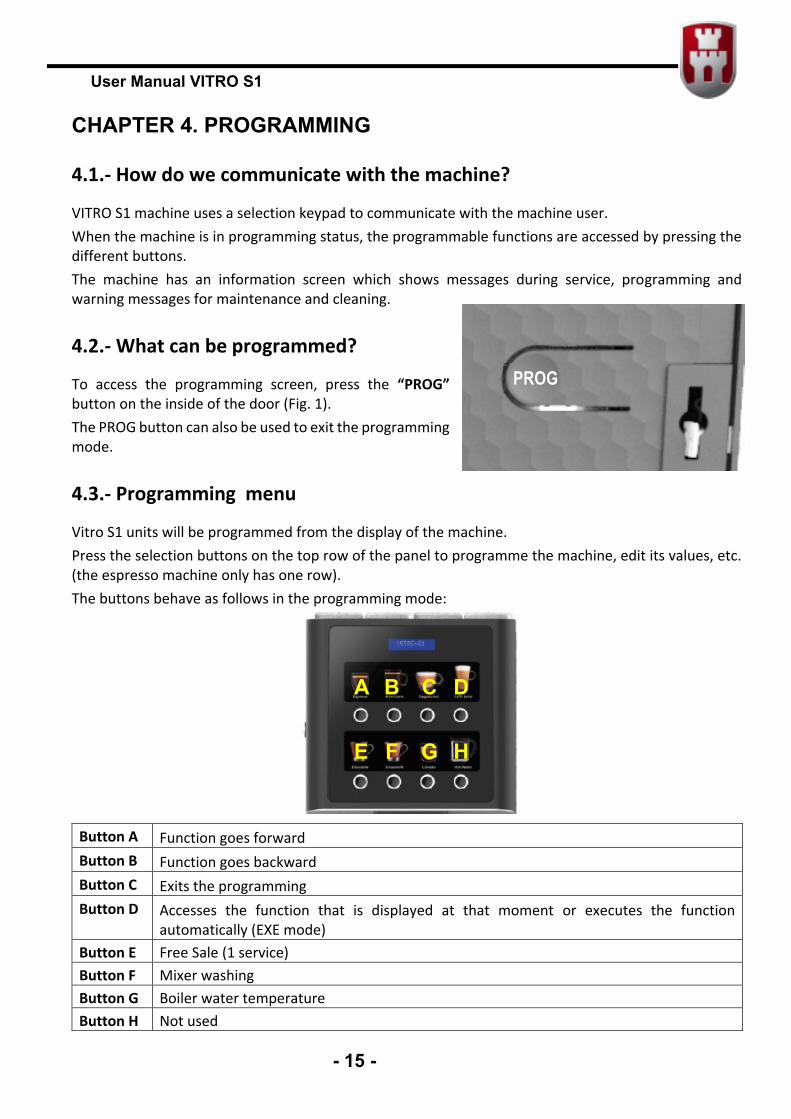
Vitro S1 units will be programmed from the display of the machine. Press the selection buttons on the top row of the panel to programme the machine, edit its values, etc. (the espresso machine only has one row). The buttons behave as follows in the programming mode:
Button A Function goes forward Button B Function goes backward Button C Exits the programming Button D Accesses the function that is displayed at that moment or executes the function
automatically (EXE mode) Button E Free Sale (1 service) Button F Mixer washing Button G Boiler water temperature Button H Not used
A B C D
E F G H
PROG
User Manual VITRO S1
- 16 -
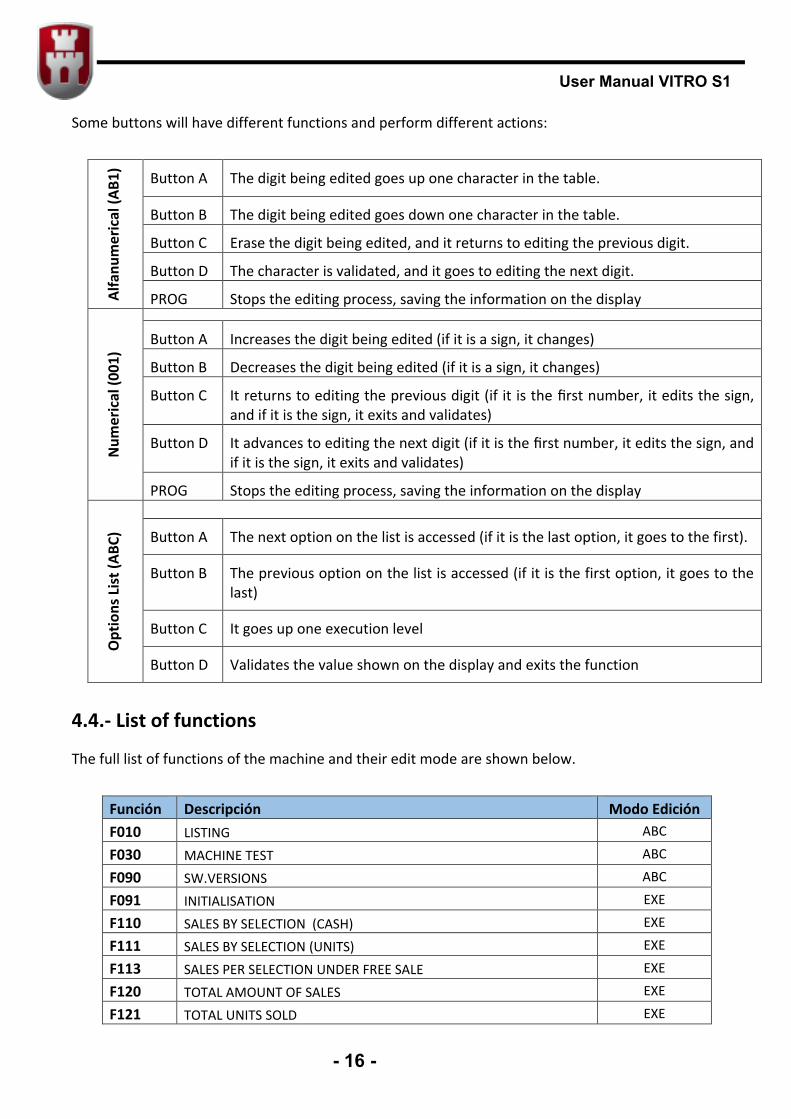
Some buttons will have different functions and perform different actions:
Alfa
num
eric
al (A
B1)
Button A The digit being edited goes up one character in the table.
Button B The digit being edited goes down one character in the table.
Button C Erase the digit being edited, and it returns to editing the previous digit.
Button D The character is validated, and it goes to editing the next digit.
PROG Stops the editing process, saving the information on the display
Num
eric
al (0
01)
Button A Increases the digit being edited (if it is a sign, it changes)
Button B Decreases the digit being edited (if it is a sign, it changes)
Button C It returns to editing the previous digit (if it is the first number, it edits the sign, and if it is the sign, it exits and validates)
Button D It advances to editing the next digit (if it is the first number, it edits the sign, and if it is the sign, it exits and validates)
PROG Stops the editing process, saving the information on the display
Opt
ions
Lis
t (AB
C)
Button A The next option on the list is accessed (if it is the last option, it goes to the first).
Button B The previous option on the list is accessed (if it is the first option, it goes to the last)
Button C It goes up one execution level
Button D Validates the value shown on the display and exits the function
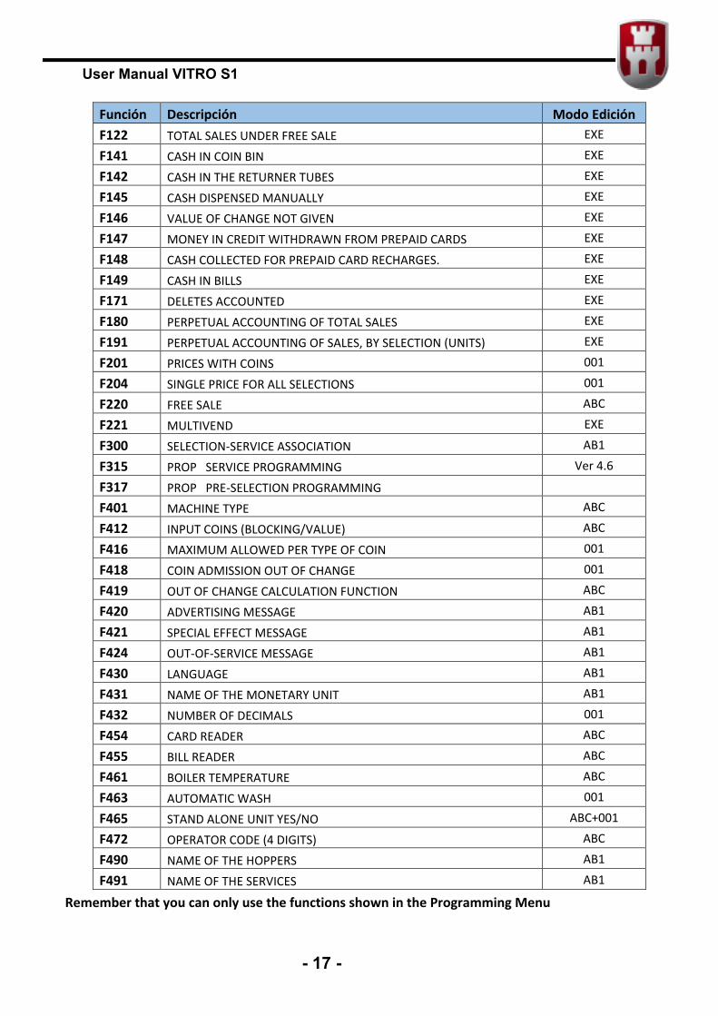
4.4.- List of functions
The full list of functions of the machine and their edit mode are shown below.
Función Descripción Modo Edición F010 LISTING ABC
F030 MACHINE TEST ABC
F090 SW.VERSIONS ABC
F091 INITIALISATION EXE
F110 SALES BY SELECTION (CASH) EXE
F111 SALES BY SELECTION (UNITS) EXE
F113 SALES PER SELECTION UNDER FREE SALE EXE
F120 TOTAL AMOUNT OF SALES EXE
F121 TOTAL UNITS SOLD EXE
User Manual VITRO S1
- 17 -
Función Descripción Modo Edición F122 TOTAL SALES UNDER FREE SALE EXE
F141 CASH IN COIN BIN EXE
F142 CASH IN THE RETURNER TUBES EXE
F145 CASH DISPENSED MANUALLY EXE
F146 VALUE OF CHANGE NOT GIVEN EXE
F147 MONEY IN CREDIT WITHDRAWN FROM PREPAID CARDS EXE
F148 CASH COLLECTED FOR PREPAID CARD RECHARGES. EXE
F149 CASH IN BILLS EXE
F171 DELETES ACCOUNTED EXE
F180 PERPETUAL ACCOUNTING OF TOTAL SALES EXE
F191 PERPETUAL ACCOUNTING OF SALES, BY SELECTION (UNITS) EXE
F201 PRICES WITH COINS 001
F204 SINGLE PRICE FOR ALL SELECTIONS 001
F220 FREE SALE ABC
F221 MULTIVEND EXE
F300 SELECTION-SERVICE ASSOCIATION AB1
F315 PROP SERVICE PROGRAMMING Ver 4.6
F317 PROP PRE-SELECTION PROGRAMMING
F401 MACHINE TYPE ABC
F412 INPUT COINS (BLOCKING/VALUE) ABC
F416 MAXIMUM ALLOWED PER TYPE OF COIN 001
F418 COIN ADMISSION OUT OF CHANGE 001
F419 OUT OF CHANGE CALCULATION FUNCTION ABC
F420 ADVERTISING MESSAGE AB1
F421 SPECIAL EFFECT MESSAGE AB1
F424 OUT-OF-SERVICE MESSAGE AB1
F430 LANGUAGE AB1
F431 NAME OF THE MONETARY UNIT AB1
F432 NUMBER OF DECIMALS 001
F454 CARD READER ABC
F455 BILL READER ABC
F461 BOILER TEMPERATURE ABC
F463 AUTOMATIC WASH 001
F465 STAND ALONE UNIT YES/NO ABC+001
F472 OPERATOR CODE (4 DIGITS) ABC
F490 NAME OF THE HOPPERS AB1
F491 NAME OF THE SERVICES AB1
Remember that you can only use the functions shown in the Programming Menu
User Manual VITRO S1
- 18 -
4.5.- Customising the Programming Menu
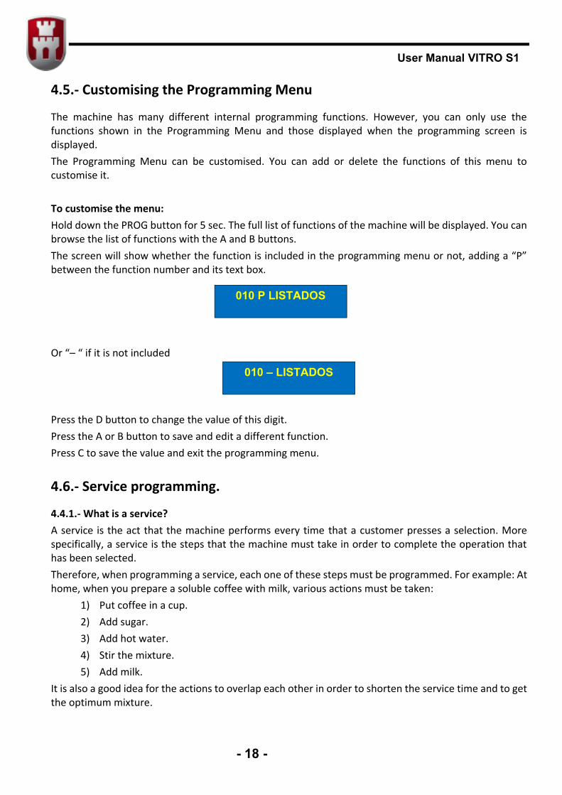
The machine has many different internal programming functions. However, you can only use the functions shown in the Programming Menu and those displayed when the programming screen is displayed. The Programming Menu can be customised. You can add or delete the functions of this menu to customise it. To customise the menu: Hold down the PROG button for 5 sec. The full list of functions of the machine will be displayed. You can browse the list of functions with the A and B buttons. The screen will show whether the function is included in the programming menu or not, adding a “P” between the function number and its text box. Or “– “ if it is not included Press the D button to change the value of this digit. Press the A or B button to save and edit a different function. Press C to save the value and exit the programming menu.
4.6.- Service programming.
4.4.1.- What is a service? A service is the act that the machine performs every time that a customer presses a selection. More specifically, a service is the steps that the machine must take in order to complete the operation that has been selected. Therefore, when programming a service, each one of these steps must be programmed. For example: At home, when you prepare a soluble coffee with milk, various actions must be taken:
1) Put coffee in a cup. 2) Add sugar. 3) Add hot water. 4) Stir the mixture. 5) Add milk.
It is also a good idea for the actions to overlap each other in order to shorten the service time and to get the optimum mixture.
010 P LISTADOS
010 – LISTADOS
User Manual VITRO S1
- 19 -
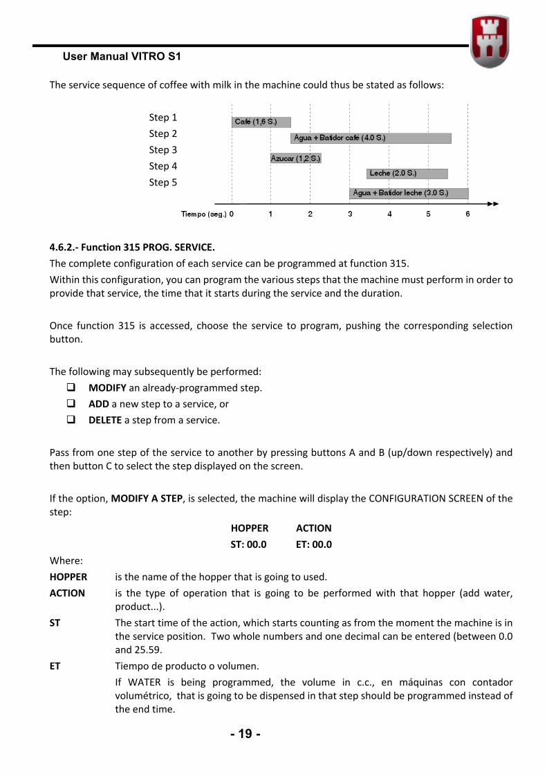
The service sequence of coffee with milk in the machine could thus be stated as follows:
Step 1 Step 2 Step 3 Step 4 Step 5
4.6.2.- Function 315 PROG. SERVICE. The complete configuration of each service can be programmed at function 315. Within this configuration, you can program the various steps that the machine must perform in order to provide that service, the time that it starts during the service and the duration. Once function 315 is accessed, choose the service to program, pushing the corresponding selection button. The following may subsequently be performed: MODIFY an already-programmed step. ADD a new step to a service, or DELETE a step from a service.
Pass from one step of the service to another by pressing buttons A and B (up/down respectively) and then button C to select the step displayed on the screen. If the option, MODIFY A STEP, is selected, the machine will display the CONFIGURATION SCREEN of the step:
HOPPER ACTION ST: 00.0 ET: 00.0
Where: HOPPER is the name of the hopper that is going to used. ACTION is the type of operation that is going to be performed with that hopper (add water,
product...). ST The start time of the action, which starts counting as from the moment the machine is in
the service position. Two whole numbers and one decimal can be entered (between 0.0 and 25.59.
ET Tiempo de producto o volumen. If WATER is being programmed, the volume in c.c., en máquinas con contador
volumétrico, that is going to be dispensed in that step should be programmed instead of the end time.
User Manual VITRO S1
- 20 -
After choosing the step to edit, start editing. The field to be edited flashes (it can be the field of the name of the hopper, the type of step or one of the digits in the time or volume values). Button D only works when editing the 2nd digit or higher. Finish by pressing PROG. In each step, the start time, the action to be performed and what hopper or blender is going to perform the action and its time in seconds must all be programmed. After finishing the programming of each step, the screen will display the programming and then the next step can be programmed.
If ADD A STEP has been selected, direct access to the new step will be provided. The procedure is the same as the aforementioned one.
If DELETE A STEP is selected, select the step (pressing 1 or 2) and then delete it (pressing 3). NOTE: If P is pressed at any time during the programming of a step, programming will be exited and the data will not be recorded
User Manual VITRO S1
- 21 -
CHAPTER 5 – TROUBLESHOOTING AND MAINTENANCE
5.1 - Reset
If your machine is out of service, enter and exit programming by pressing the PROG button twice.
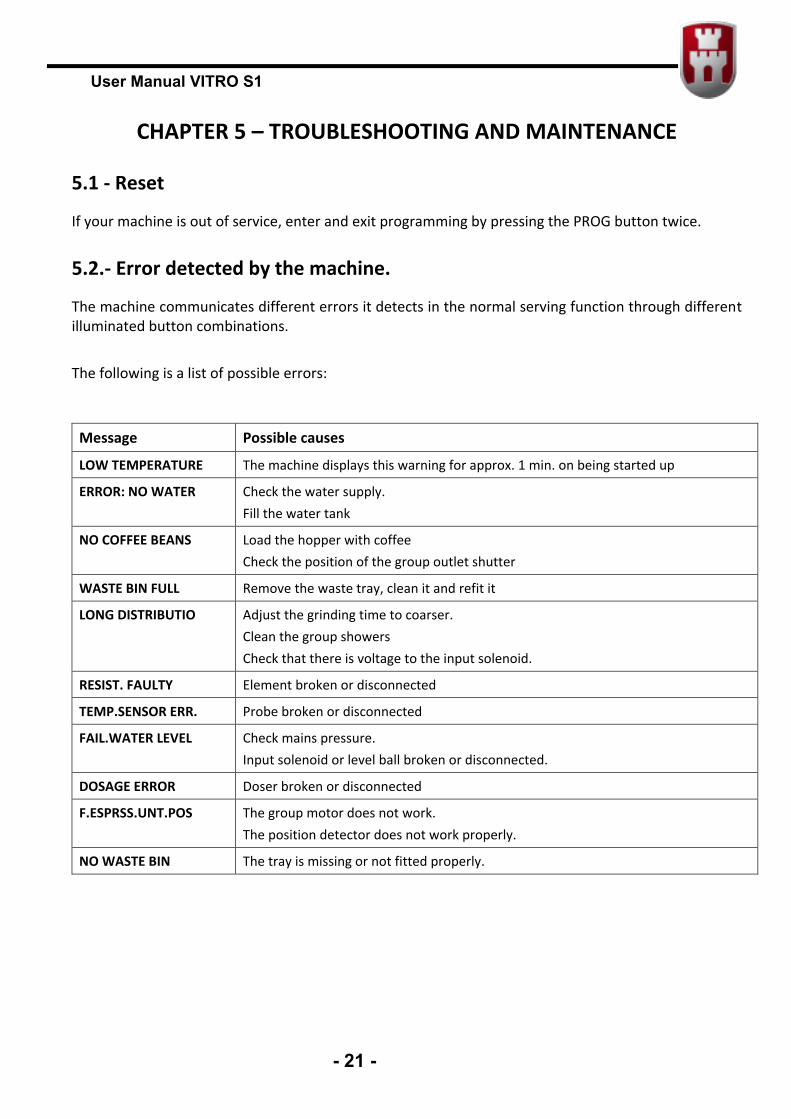
5.2.- Error detected by the machine.
The machine communicates different errors it detects in the normal serving function through different illuminated button combinations. The following is a list of possible errors:
Message Possible causes
LOW TEMPERATURE The machine displays this warning for approx. 1 min. on being started up
ERROR: NO WATER Check the water supply. Fill the water tank
NO COFFEE BEANS Load the hopper with coffee Check the position of the group outlet shutter
WASTE BIN FULL Remove the waste tray, clean it and refit it
LONG DISTRIBUTIO Adjust the grinding time to coarser. Clean the group showers Check that there is voltage to the input solenoid.
RESIST. FAULTY Element broken or disconnected
TEMP.SENSOR ERR. Probe broken or disconnected
FAIL.WATER LEVEL Check mains pressure. Input solenoid or level ball broken or disconnected.
DOSAGE ERROR Doser broken or disconnected
F.ESPRSS.UNT.POS The group motor does not work. The position detector does not work properly.
NO WASTE BIN The tray is missing or not fitted properly.
User Manual VITRO S1
- 22 -
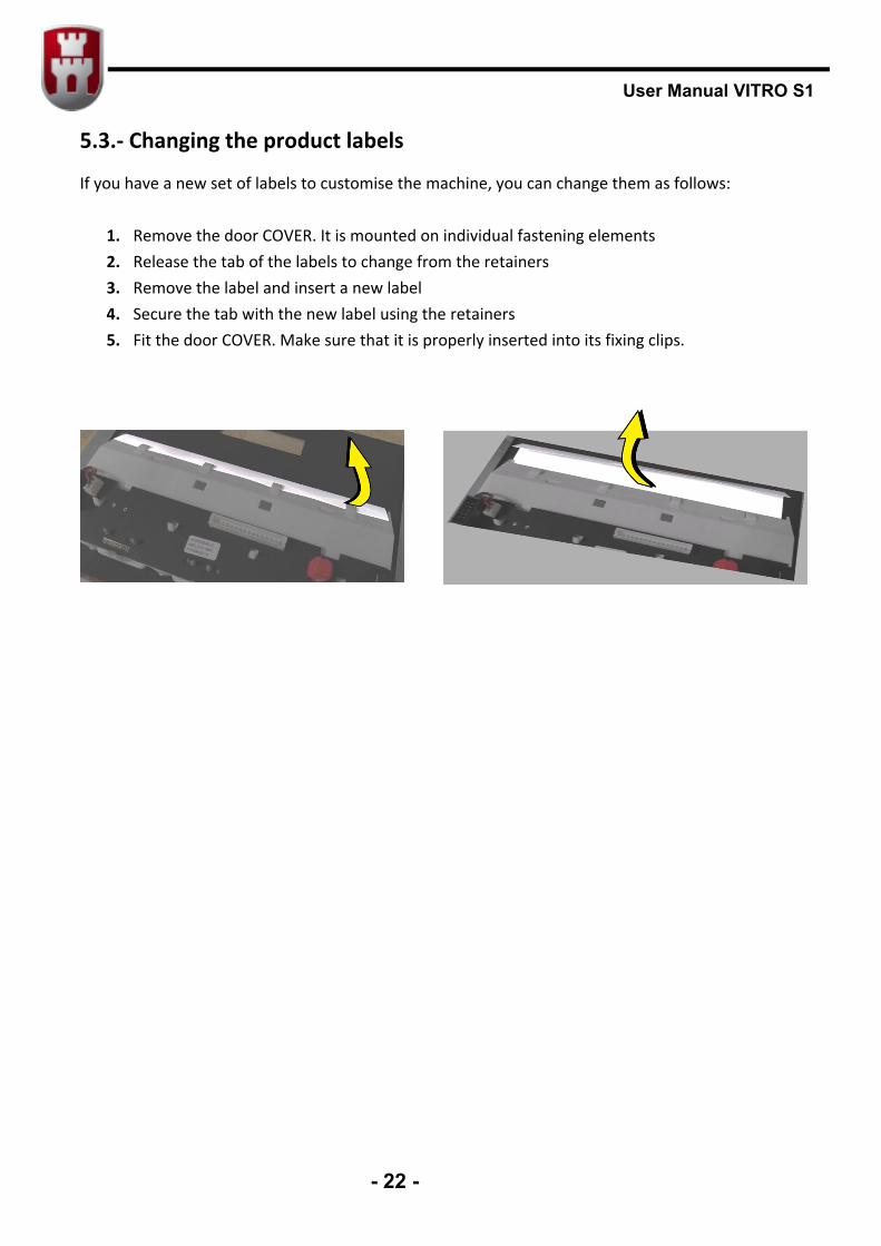
5.3.- Changing the product labels
If you have a new set of labels to customise the machine, you can change them as follows:
1. Remove the door COVER. It is mounted on individual fastening elements 2. Release the tab of the labels to change from the retainers 3. Remove the label and insert a new label 4. Secure the tab with the new label using the retainers 5. Fit the door COVER. Make sure that it is properly inserted into its fixing clips.
User Manual VITRO S1
- 23 -
CHAPTER 6. CLEANING THE MACHINE.
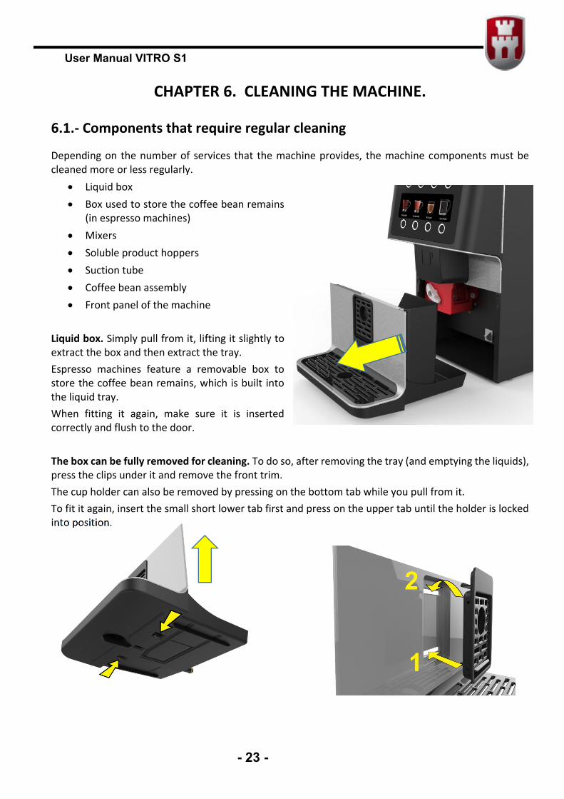
6.1.- Components that require regular cleaning
Depending on the number of services that the machine provides, the machine components must be cleaned more or less regularly.
Liquid box Box used to store the coffee bean remains
(in espresso machines) Mixers Soluble product hoppers Suction tube Coffee bean assembly Front panel of the machine
Liquid box. Simply pull from it, lifting it slightly to extract the box and then extract the tray. Espresso machines feature a removable box to store the coffee bean remains, which is built into the liquid tray. When fitting it again, make sure it is inserted correctly and flush to the door. The box can be fully removed for cleaning. To do so, after removing the tray (and emptying the liquids), press the clips under it and remove the front trim. The cup holder can also be removed by pressing on the bottom tab while you pull from it. To fit it again, insert the small short lower tab first and press on the upper tab until the holder is locked into position.

User Manual VITRO S1
- 24 -
Mixers. Pull from the mixer to extract it and clean it or replace it with a clean mixer. Remember to fit the outlet elbows of the hoppers facing upwards to avoid the product from falling out and staining the machine when the mixer is removed. When the clean mixer has been inserted, fit the rubber stops again and the outlet elbows onto the hoppers Soluble product hoppers. The soluble product hoppers are extracted by pulling from them, from the top of the machine. Remember to turn the
elbows to prevent the product from falling out and being dropped on the machine. If you wish to clean the machine thoroughly, remove the hoppers and remove the suction tube onto which the hoppers are placed (Fig. 1).
6.2.- Regular cleaning of the machine and maintenance operations
The following table details the recommended cleaning and frequency:
Once a week or every 700 services
Clean the mixer (Press F) Clean the surface of the mixer area Drain the spill tray Clean the services compartment Clean the front of the machine after all the above operations have been
done Once a month or every 5,000 services
Remove the mixer blades. Wash with hot water Remove the product hoppers and clean the base of the area Clean intake manifolds
Once a year or every 25,000 services
Perform all of the above. Change the coffee filter of the group (see 3.7). Wash the filter using the Cleaning Cycle (see 6.3), or retreat to thoroughly
clean with detergent Once every 4 years or every 20,000 services
Check the wheels of the grinder and replace if necessary.
6.3.- Cleaning cycle for the group brewing chamber
For hygiene reasons, this process should be performed at least once every three months in order to eliminate coffee particles from the brewing chamber.
User Manual VITRO S1
- 25 -
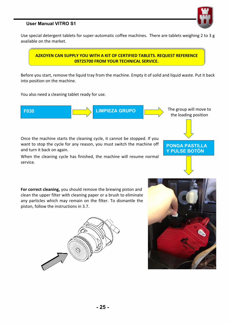
Use special detergent tablets for super-automatic coffee machines. There are tablets weighing 2 to 3 g available on the market. Before you start, remove the liquid tray from the machine. Empty it of solid and liquid waste. Put it back into position on the machine. You also need a cleaning tablet ready for use.
Once the machine starts the cleaning cycle, it cannot be stopped. If you want to stop the cycle for any reason, you must switch the machine off and turn it back on again. When the cleaning cycle has finished, the machine will resume normal service. For correct cleaning, you should remove the brewing piston and clean the upper filter with cleaning paper or a brush to eliminate any particles which may remain on the filter. To dismantle the piston, follow the instructions in 3.7.
F030 LIMPIEZA GRUPO The group will move to the loading position
PONGA PASTILLA Y PULSE BOTÓN
AZKOYEN CAN SUPPLY YOU WITH A KIT OF CERTIFIED TABLETS. REQUEST REFERENCE 09725700 FROM YOUR TECHNICAL SERVICE.
User Manual VITRO S1
- 26 -
6.4.- Descaling cycle.
This process should be performed at least once every 3 months unless anti-scale filters or pre-filtered water are being used. The process lasts approximately 30 minutes and must not be cut short. The benefits obtained from this process are:
Longer life for your VITRO S1 coffee machine Prevention of machine operation faults
If the lime removal process is not completed correctly, lime remains might remain inside the machine, which will generate new lime remains more quickly and could damage the machine. You will need:
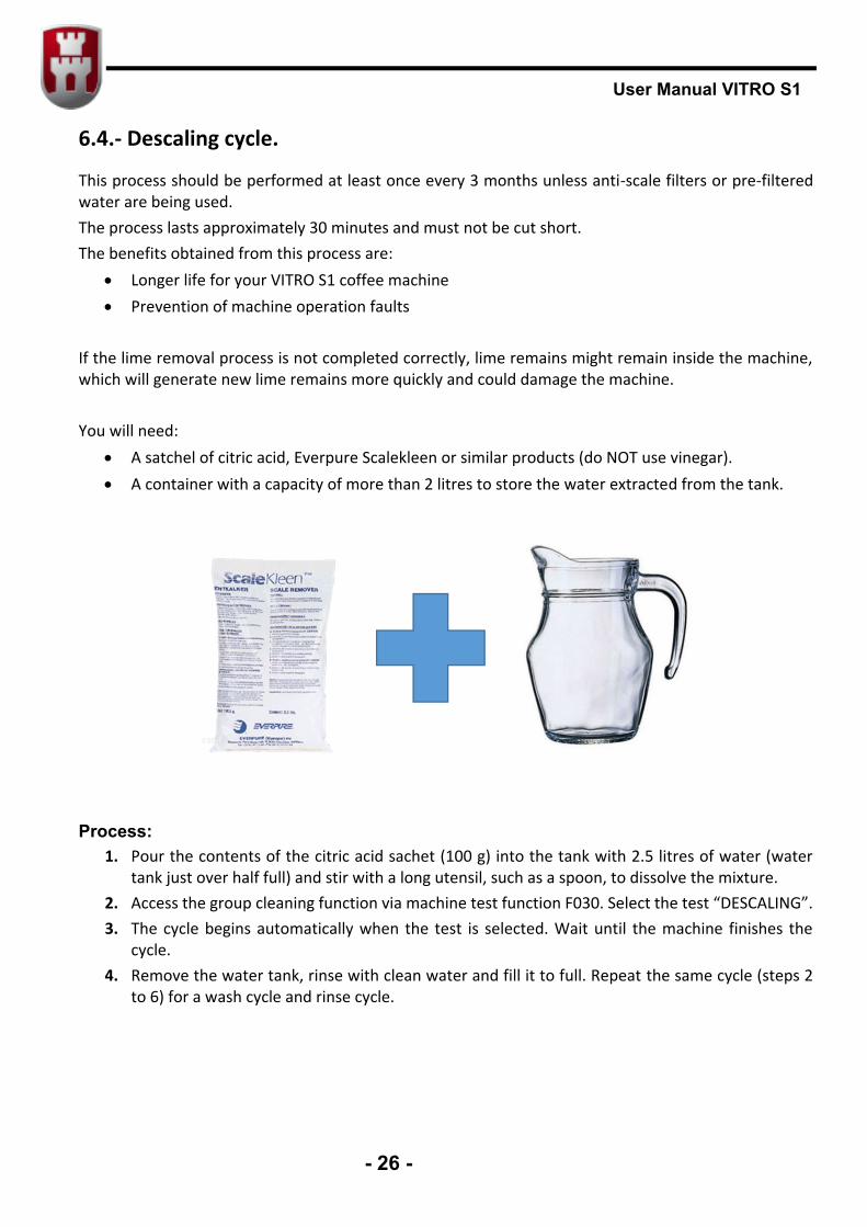
A satchel of citric acid, Everpure Scalekleen or similar products (do NOT use vinegar). A container with a capacity of more than 2 litres to store the water extracted from the tank.
Process:
1. Pour the contents of the citric acid sachet (100 g) into the tank with 2.5 litres of water (water tank just over half full) and stir with a long utensil, such as a spoon, to dissolve the mixture.
2. Access the group cleaning function via machine test function F030. Select the test “DESCALING”. 3. The cycle begins automatically when the test is selected. Wait until the machine finishes the
cycle. 4. Remove the water tank, rinse with clean water and fill it to full. Repeat the same cycle (steps 2
to 6) for a wash cycle and rinse cycle.
User Manual VITRO S1
- 27 -
6.5.- Replacing the water filter
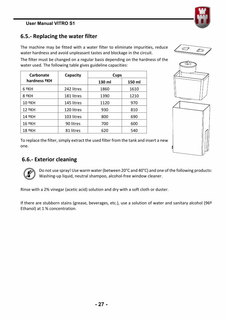
The machine may be fitted with a water filter to eliminate impurities, reduce water hardness and avoid unpleasant tastes and blockage in the circuit. The filter must be changed on a regular basis depending on the hardness of the water used. The following table gives guideline capacities:
To replace the filter, simply extract the used filter from the tank and insert a new one.
6.6.- Exterior cleaning
Do not use spray! Use warm water (between 20°C and 40°C) and one of the following products: Washing-up liquid, neutral shampoo, alcohol-free window cleaner.
Rinse with a 2% vinegar (acetic acid) solution and dry with a soft cloth or duster. If there are stubborn stains (grease, beverages, etc.), use a solution of water and sanitary alcohol (96º Ethanol) at 1 % concentration.
Carbonate hardness ºKH
Capacity Cups 130 ml 150 ml
6 ºKH 242 litres 1860 1610 8 ºKH 181 litres 1390 1210 10 ºKH 145 litres 1120 970 12 ºKH 120 litres 930 810 14 ºKH 103 litres 800 690 16 ºKH 90 litres 700 600 18 ºKH 81 litres 620 540
User Manual VITRO S1
- 28 -
Anexe 1. THE TREATMENT, COLLECTION, RECYCLING AND DISPOSAL OF THIS DEVICE DIRECTIVE 2002/96/CE ON THE TREATMENT, COLLECTION, RECYCLING AND DISPOSAL OF ELECTRIC AND ELECTRONIC DEVICES AND THEIR COMPONENTS
INFORMATION 1. For countries in the european union (EU) The disposal of electric and electronic devices as solid urban waste is strictly prohibited: it must be collected separately. The dumping of these devices at unequipped and unauthorized places may have hazardous effects on health and the environment. Offenders will be subjected to the penalties and measures laid down by the law. To dispose of our devices correctly
a) Contact the Local Authorities, who will give you the practical information you need and the instructions for handling the
b) waste correctly, for example: location and times of the waste collection centres, etc. c) When you purchase a new device of ours, give a used device similar to the one purchased to our
dealer for disposal. The crossed dustbin symbol on the device means that: - When it to be disposed of, the device is to be taken to the equipped waste collection centres and is to be handled separately from urban waste; - The producer guarantees the activation of the treatment, collection, recycling and disposal procedures in accordance with Directive 2002/96/CE (and subsequent amendments).
2. For other countries (not in the EU) The treatment, collection, recycling and disposal of electric and electronic devices will be carried out in accordance with the laws in force in the country in question

User Manual VITRO S1
- 29 -