Embed Size (px)
Citation preview
Using Yaskawa CM049 BACnet Option with Delta Controls DSM-RTR
1. INTRODUCTION:
The following information describes utilizing the Yaskawa E7U and P7U Variable Frequency Drives with Yaskawa’s CM049 BACnet Option to achieve BACnet control, monitoring and parameter access. This document contains the general setup, connections, drive parameters and gateway objects available to the E7U and P7U drives.
Before either the drives or any of the supporting devices are connected, review the associated user and/or technical manuals. Read and follow all safety precautions.
2. INTENDED AUDIENCE:
This document assumes that the reader is familiar with Yaskawa E7U and P7U Drives, BACnet, BACnet MS/TP and RS485.
3. REFERENCES:
All Yaskawa documents listed below are available from the Yaskawa web site: www.Yaskawa.com. Check www.Deltacontrols.com for Delta specific literature. For BACnet refer to www.ashrae.org or www.bacnet.org . E7 User Manual -- TM.E7.01 E7 Programming Manual -- TM.E7.02 P7 User Manual -- TM.P7.01 P7 Programming Manual -- TM.P7.02 BACnet Option Installation Guide – IG.AFD.23 Delta’s DSM-RTR_Installation_Guide.pdf
4. TERMS:
BACnet Building Automation Control network
Modbus RTU A subset of the Modbus Protocol. In this case, functions 0x03, 0x06, 0x08 and 0x10 are supported.
MS/TP Master/Slave Token Passing
Yaskawa Electric America, Inc. www.Yaskawa.com AN.AFD.12 Page 1 of 10 02/12/2008 Rev: 08-02
Yaskawa Electric America, Inc. www.Yaskawa.com AN.AFD.12 Page 2 of 10 02/12/2008 Rev: 08-02
5. SETUP:
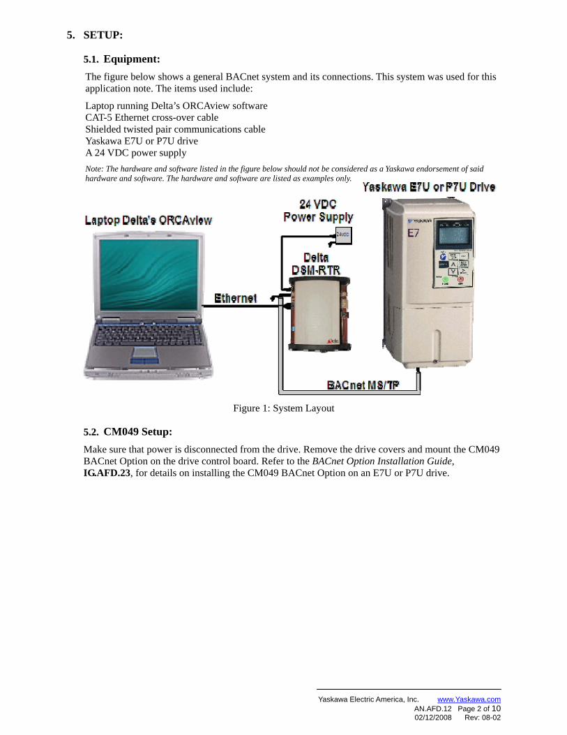
5.1.5.1. Equipment: The figure below shows a general BACnet system and its connections. This system was used for this application note. The items used include:
Laptop running Delta’s ORCAview software CAT-5 Ethernet cross-over cable Shielded twisted pair communications cable Yaskawa E7U or P7U drive A 24 VDC power supply Note: The hardware and software listed in the figure below should not be considered as a Yaskawa endorsement of said hardware and software. The hardware and software are listed as examples only.
Figure 1: System Layout
5.2.5.2. CM049 Setup: Make sure that power is disconnected from the drive. Remove the drive covers and mount the CM049 BACnet Option on the drive control board. Refer to the BACnet Option Installation Guide, IG.AFD.23, for details on installing the CM049 BACnet Option on an E7U or P7U drive.
Yaskawa Electric America, Inc. www.Yaskawa.com AN.AFD.12 Page 3 of 10 02/12/2008 Rev: 08-02
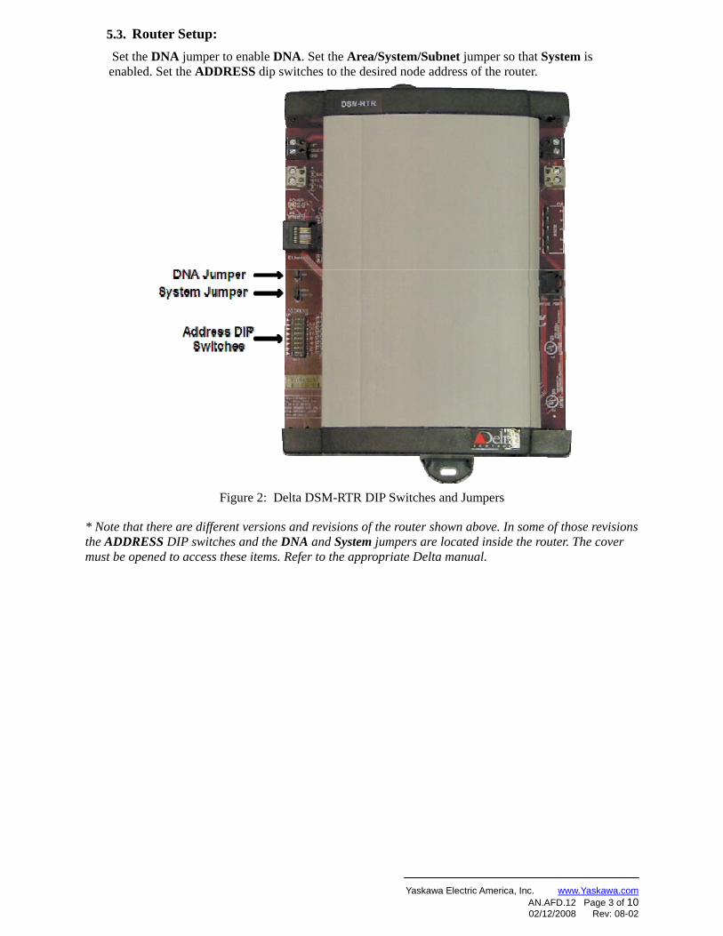
5.3.5.3. Router Setup: Set the DNA jumper to enable DNA. Set the Area/System/Subnet jumper so that System is enabled. Set the ADDRESS dip switches to the desired node address of the router.
Figure 2: Delta DSM-RTR DIP Switches and Jumpers
* Note that there are different versions and revisions of the router shown above. In some of those revisions the ADDRESS DIP switches and the DNA and System jumpers are located inside the router. The cover must be opened to access these items. Refer to the appropriate Delta manual.
Yaskawa Electric America, Inc. www.Yaskawa.com AN.AFD.12 Page 4 of 10 02/12/2008 Rev: 08-02
Connections
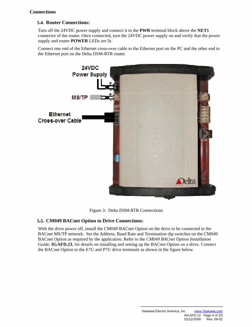
5.4.5.4. Router Connections: Turn off the 24VDC power supply and connect it to the PWR terminal block above the NET1 connector of the router. Once connected, turn the 24VDC power supply on and verify that the power supply and router POWER LEDs are lit.
Connect one end of the Ethernet cross-over cable to the Ethernet port on the PC and the other end to the Ethernet port on the Delta DSM-RTR router.
Figure 3: Delta DSM-RTR Connections
5.5.5.5. CM049 BACnet Option to Drive Connections: With the drive power off, install the CM049 BACnet Option on the drive to be connected to the BACnet MS/TP network. Set the Address, Baud Rate and Termination dip switches on the CM049 BACnet Option as required by the application. Refer to the CM049 BACnet Option Installation Guide, IG.AFD.23, for details on installing and setting up the BACnet Option on a drive. Connect the BACnet Option to the E7U and P7U drive terminals as shown in the figure below.
Yaskawa Electric America, Inc. www.Yaskawa.com AN.AFD.12 Page 5 of 10 02/12/2008 Rev: 08-02
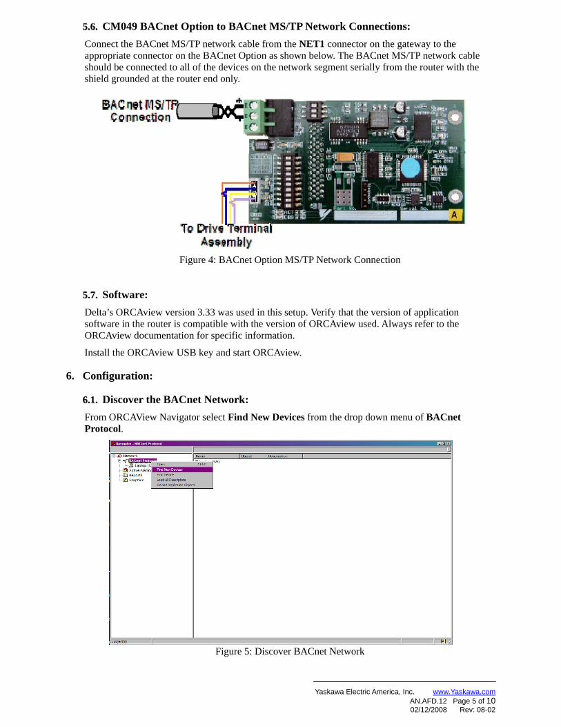
5.6.5.6. CM049 BACnet Option to BACnet MS/TP Network Connections: Connect the BACnet MS/TP network cable from the NET1 connector on the gateway to the appropriate connector on the BACnet Option as shown below. The BACnet MS/TP network cable should be connected to all of the devices on the network segment serially from the router with the shield grounded at the router end only.
Figure 4: BACnet Option MS/TP Network Connection
5.7.5.7. Software: Delta’s ORCAview version 3.33 was used in this setup. Verify that the version of application software in the router is compatible with the version of ORCAview used. Always refer to the ORCAview documentation for specific information.
Install the ORCAview USB key and start ORCAview.
6. Configuration:
6.1.6.1. Discover the BACnet Network: From ORCAView Navigator select Find New Devices from the drop down menu of BACnet Protocol.
Figure 5: Discover BACnet Network
Yaskawa Electric America, Inc. www.Yaskawa.com AN.AFD.12 Page 6 of 10 02/12/2008 Rev: 08-02
6.2.6.2. Configure Router:
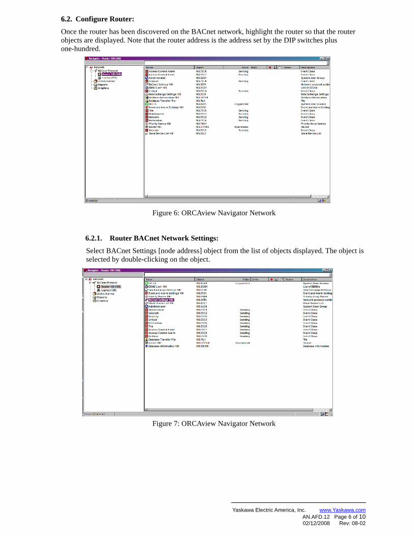
Once the router has been discovered on the BACnet network, highlight the router so that the router objects are displayed. Note that the router address is the address set by the DIP switches plus one-hundred.
Figure 6: ORCAview Navigator Network
6.2.1. Router BACnet Network Settings:
Select BACnet Settings [node address] object from the list of objects displayed. The object is selected by double-clicking on the object.
Figure 7: ORCAview Navigator Network
Yaskawa Electric America, Inc. www.Yaskawa.com AN.AFD.12 Page 7 of 10 02/12/2008 Rev: 08-02
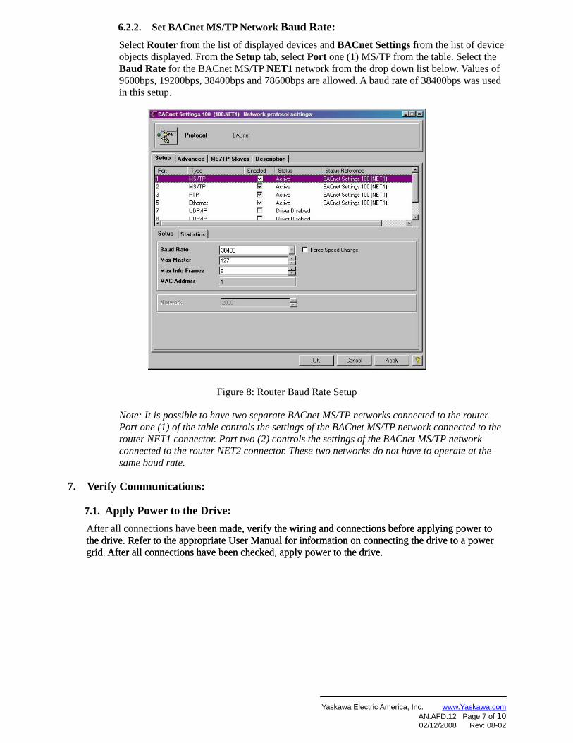
6.2.2. Set BACnet MS/TP Network Baud Rate: Select Router from the list of displayed devices and BACnet Settings from the list of device objects displayed. From the Setup tab, select Port one (1) MS/TP from the table. Select the Baud Rate for the BACnet MS/TP NET1 network from the drop down list below. Values of 9600bps, 19200bps, 38400bps and 78600bps are allowed. A baud rate of 38400bps was used in this setup.
Figure 8: Router Baud Rate Setup
Note: It is possible to have two separate BACnet MS/TP networks connected to the router. Port one (1) of the table controls the settings of the BACnet MS/TP network connected to the router NET1 connector. Port two (2) controls the settings of the BACnet MS/TP network connected to the router NET2 connector. These two networks do not have to operate at the same baud rate.
7. Verify Communications:
7.1.7.1. Apply Power to the Drive: After all connections have been made, verify the wiring and connections before applying power to the drive. Refer to the appropriate User Manual for information on connecting the drive to a power grid. After all connections have been checked, apply power to the drive.
een made, verify the wiring and connections before applying power to the drive. Refer to the appropriate User Manual for information on connecting the drive to a power grid. After all connections have been checked, apply power to the drive.
Yaskawa Electric America, Inc. www.Yaskawa.com AN.AFD.12 Page 8 of 10 02/12/2008 Rev: 08-02
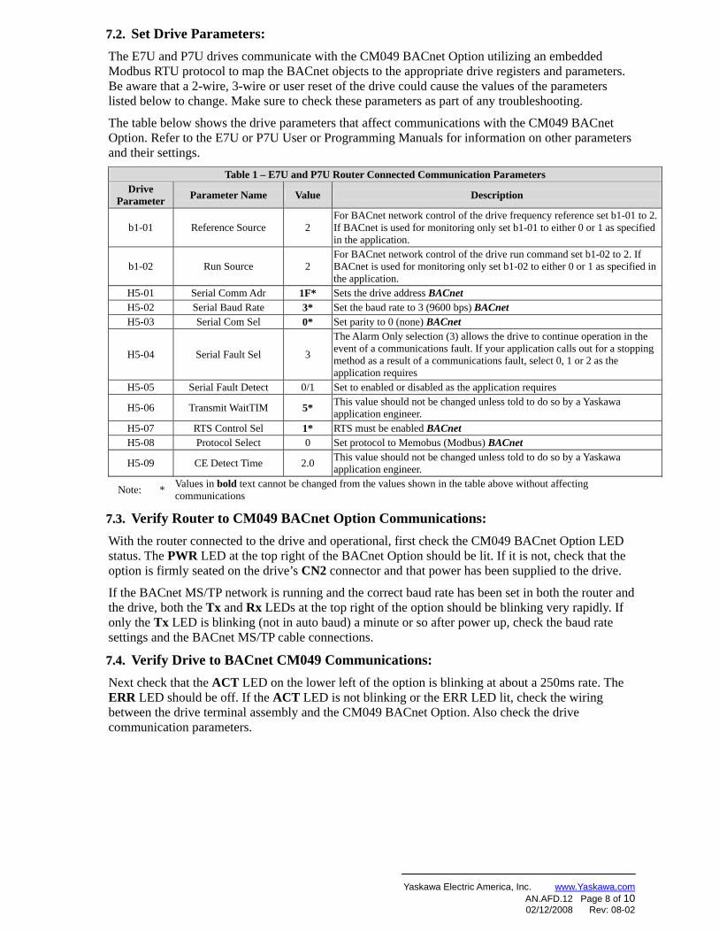
7.2.7.2. Set Drive Parameters: The E7U and P7U drives communicate with the CM049 BACnet Option utilizing an embedded Modbus RTU protocol to map the BACnet objects to the appropriate drive registers and parameters. Be aware that a 2-wire, 3-wire or user reset of the drive could cause the values of the parameters listed below to change. Make sure to check these parameters as part of any troubleshooting.
The table below shows the drive parameters that affect communications with the CM049 BACnet Option. Refer to the E7U or P7U User or Programming Manuals for information on other parameters and their settings.
Table 1 – E7U and P7U Router Connected Communication Parameters Drive
Parameter Parameter Name Value Description
b1-01 Reference Source 2 For BACnet network control of the drive frequency reference set b1-01 to 2. If BACnet is used for monitoring only set b1-01 to either 0 or 1 as specified in the application.
b1-02 Run Source 2 For BACnet network control of the drive run command set b1-02 to 2. If BACnet is used for monitoring only set b1-02 to either 0 or 1 as specified in the application.
H5-01 Serial Comm Adr 1F* Sets the drive address BACnet H5-02 Serial Baud Rate 3* Set the baud rate to 3 (9600 bps) BACnet H5-03 Serial Com Sel 0* Set parity to 0 (none) BACnet
H5-04 Serial Fault Sel 3
The Alarm Only selection (3) allows the drive to continue operation in the event of a communications fault. If your application calls out for a stopping method as a result of a communications fault, select 0, 1 or 2 as the application requires
H5-05 Serial Fault Detect 0/1 Set to enabled or disabled as the application requires
H5-06 Transmit WaitTIM 5* This value should not be changed unless told to do so by a Yaskawa application engineer.
H5-07 RTS Control Sel 1* RTS must be enabled BACnet H5-08 Protocol Select 0 Set protocol to Memobus (Modbus) BACnet
H5-09 CE Detect Time 2.0 This value should not be changed unless told to do so by a Yaskawa application engineer.
Note: * Values in bold text cannot be changed from the values shown in the table above without affecting communications
7.3.7.3. Verify Router to CM049 BACnet Option Communications: With the router connected to the drive and operational, first check the CM049 BACnet Option LED status. The PWR LED at the top right of the BACnet Option should be lit. If it is not, check that the option is firmly seated on the drive’s CN2 connector and that power has been supplied to the drive.
If the BACnet MS/TP network is running and the correct baud rate has been set in both the router and the drive, both the Tx and Rx LEDs at the top right of the option should be blinking very rapidly. If only the Tx LED is blinking (not in auto baud) a minute or so after power up, check the baud rate settings and the BACnet MS/TP cable connections.
7.4.7.4. Verify Drive to BACnet CM049 Communications: Next check that the ACT LED on the lower left of the option is blinking at about a 250ms rate. The ERR LED should be off. If the ACT LED is not blinking or the ERR LED lit, check the wiring between the drive terminal assembly and the CM049 BACnet Option. Also check the drive communication parameters.
Yaskawa Electric America, Inc. www.Yaskawa.com AN.AFD.12 Page 9 of 10 02/12/2008 Rev: 08-02
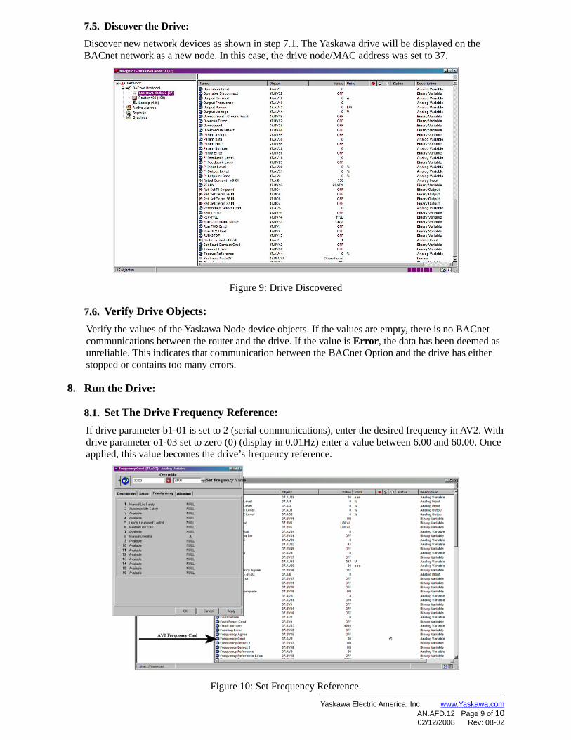
7.5.7.5. Discover the Drive:
Discover new network devices as shown in step 7.1. The Yaskawa drive will be displayed on the BACnet network as a new node. In this case, the drive node/MAC address was set to 37.
Figure 9: Drive Discovered
7.6.7.6. Verify Drive Objects: Verify the values of the Yaskawa Node device objects. If the values are empty, there is no BACnet communications between the router and the drive. If the value is Error, the data has been deemed as unreliable. This indicates that communication between the BACnet Option and the drive has either stopped or contains too many errors.
8. Run the Drive:
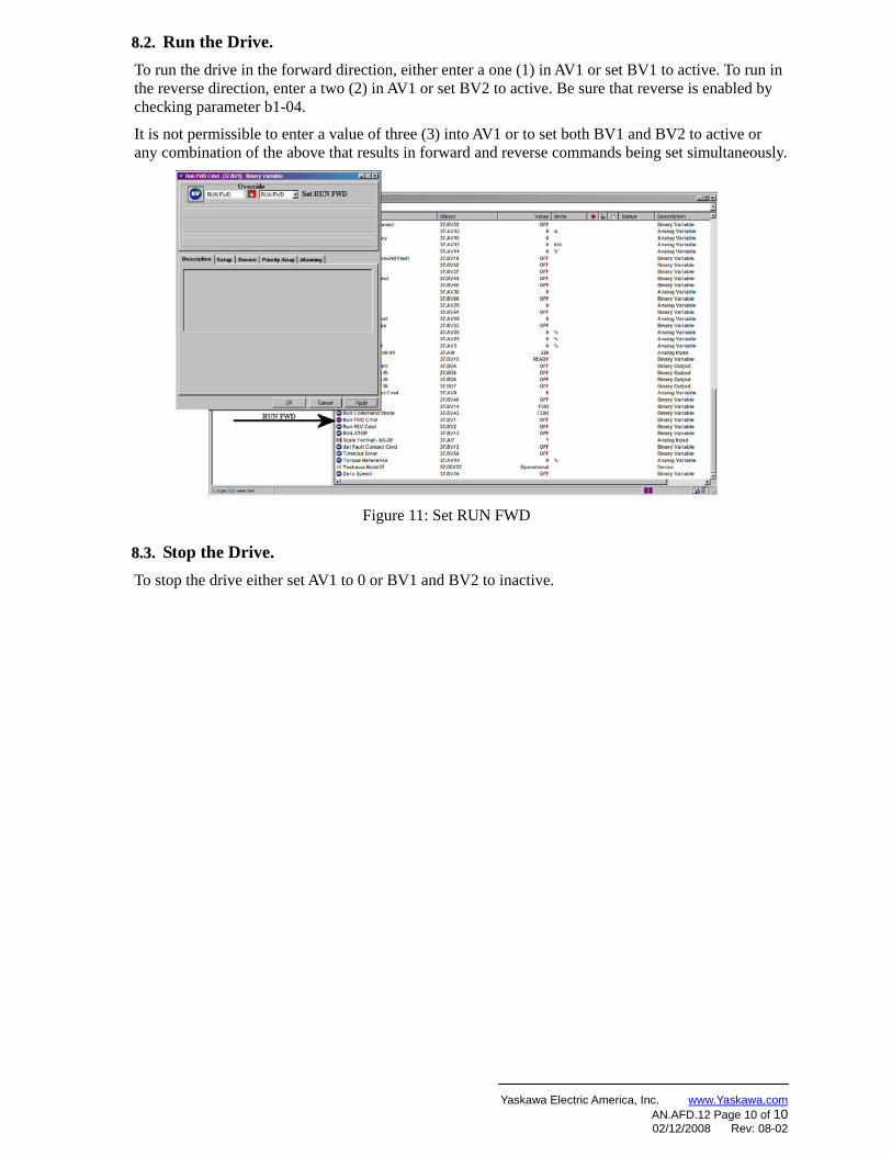
8.1.8.1. Set The Drive Frequency Reference: If drive parameter b1-01 is set to 2 (serial communications), enter the desired frequency in AV2. With drive parameter o1-03 set to zero (0) (display in 0.01Hz) enter a value between 6.00 and 60.00. Once applied, this value becomes the drive’s frequency reference.
Figure 10: Set Frequency Reference.
Yaskawa Electric America, Inc. www.Yaskawa.com AN.AFD.12 Page 10 of 10 02/12/2008 Rev: 08-02
8.2.8.2. Run the Drive. To run the drive in the forward direction, either enter a one (1) in AV1 or set BV1 to active. To run in the reverse direction, enter a two (2) in AV1 or set BV2 to active. Be sure that reverse is enabled by checking parameter b1-04.
It is not permissible to enter a value of three (3) into AV1 or to set both BV1 and BV2 to active or any combination of the above that results in forward and reverse commands being set simultaneously.
Figure 11: Set RUN FWD
8.3.8.3. Stop the Drive. To stop the drive either set AV1 to 0 or BV1 and BV2 to inactive.