Embed Size (px)
Citation preview
SOFTWARE MODULE
TRINAMIC Motion Control GmbH & Co. KG Hamburg, Germany www.trinamic.com
V 2.1
TMCM-BLDC USER MANUAL
+ + TMCM-BLDC
Adjusting Tool for
BLDC Modules
Field Orientated Control
+ +
TMCM-BLDC User Manual (Rev. 2.01 / 2013-JUN-04) 2
www.trinamic.com
Table of Contents
1 TMCM-BLDC Overview ................................................................................................................................ 3
1.1 Modes of Operation ............................................................................................................................................ 3
2 Getting Started ............................................................................................................................................ 4
2.1 Communication .................................................................................................................................................... 4
2.2 Main Dialogues ..................................................................................................................................................... 5
2.3 Status and Error Flags ........................................................................................................................................ 5
2.4 Displaying Graphs for Torque, Velocity, and Position .............................................................................. 5
2.5 Using the Fast Debug Graph ............................................................................................................................ 7
2.6 Displaying Parameter Numbers ....................................................................................................................... 7
3 Dialogues of the TMCM-BLDC .................................................................................................................. 8
3.1 Settings Dialog ..................................................................................................................................................... 8
3.2 Torque Mode Dialogue ....................................................................................................................................... 9
3.3 Velocity Mode Dialogue ................................................................................................................................... 10
3.4 Position Mode Dialogue .................................................................................................................................. 12
3.5 TMCL Direct Mode Dialogue ............................................................................................................................ 14
4 File Menu of TMCM-BLDC ....................................................................................................................... 15
5 Software Version...................................................................................................................................... 15
6 Life Support Policy .................................................................................................................................. 16
7 Revision History ....................................................................................................................................... 17
8 References .................................................................................................................................................. 17
TMCM-BLDC User Manual (Rev. 2.01 / 2013-JUN-04) 3
www.trinamic.com
1 TMCM-BLDC Overview The TMCM-BLDC is a program for adjusting and testing TRINAMIC modules for BLDC motors. The software tool can be downloaded from www.trinamic.com and is compatible with the TMCL-IDE. The TMCM-BLDC is a PC application running under Windows XP, Vista, and Windows 7 (Windows 3.x is not supported) that includes
- a connection dialogue for connecting the module, - a dialogue for basic settings (motor settings, encoder settings, commutation mode, trace
controller), - three dialogues for operation modes, each for one mode of operation (torque mode, velocity
mode, position mode), - a dialogue for entering and executing TMCL commands in direct mode, - a file menu for exporting and importing settings, storing or restoring them.
The TMCM-BLDC is designed for finding initial settings, e.g. values for P and I parameters of a specific mode of operation. Each value can be changed on the fly and the result is shown immediately on the polled diagrams. Proved values can be exported to the TMCL-IDE for developing programs that run standalone on the module later on. TRINIAMIC recommends evaluating optimal settings for your module with the TMCM-BLDC tool. The TMCL-IDE offers another BLDC dialogue for setting and testing parameter values. At least, a customer may decide himself, which software tool comes up best to his requirements.
1.1 Modes of Operation The TMCM-BLDC provides three modes of operation. The current regulation in torque mode has to be configured fist. Then, the velocity PI regulation has to be done in velocity mode. At this point, basic settings are nearly complete and positioning in position mode is possible after adjusting the position P regulator. Please switch between all modes of operation to meet your needs.
TORQUE MODE
The torque mode allows operating the motor at constant torque. This kind of operation may be required in robotics applications or in applications where the actual velocity is controlled by a different drive. Torque becomes stabilized in the desired direction independent of the actual motion direction. The maximum velocity in this mode is only limited by the motor characteristics and the current setting.
VELOCITY MODE
The velocity mode can be used in case the focus of an application is on specific velocities (e.g. for ventilation or pumps). The drive will work in a four-quadrant mode in order to keep the target velocity, i.e. it will break or accelerate the motor. The torque in this mode of operation is limited by the maximum current setting.
POSITION MODE
Position mode is obvious in case relative or absolute positions have to be reached exactly (e.g. for camera systems or special medical applications). The motor moves to a desired position or keeps a desired position. The torque to enforce the target position is limited by the current setting. Limits for velocity and acceleration have to be set in advance.
TMCM-BLDC User Manual (Rev. 2.01 / 2013-JUN-04) 4
www.trinamic.com
2 Getting Started Please refer to the specific hardware and firmware manuals of your module for detailed information about connecting cables etc.
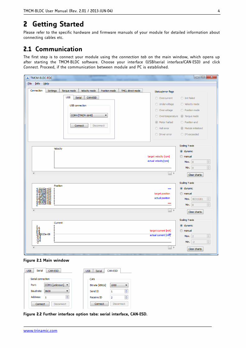
2.1 Communication The first step is to connect your module using the connection tab on the main window, which opens up after starting the TMCM-BLDC software. Choose your interface (USB/serial interface/CAN-ESD) and click Connect. Proceed, if the communication between module and PC is established.
Figure 2.1 Main window
Figure 2.2 Further interface option tabs: serial interface, CAN-ESD.
TMCM-BLDC User Manual (Rev. 2.01 / 2013-JUN-04) 5
www.trinamic.com
2.2 Main Dialogues The TMCM-BLDC mainly consists of the following dialogues:
- The settings tab is used for general settings of the module.
- The torque mode tab is used for setting current limits and configuring torque mode operation of the module. The motor can be driven in torque mode, here.
- The velocity mode tab is used for setting velocity limits and driving the motor in velocity mode.
- The position mode is used for adjusting the position P regulator and moving the motor in position mode.
- The TMCL direct mode tab is used for controlling and driving the module in TMCL direct mode. (For standalone operation of the module, use the TMCL-IDE.)
2.3 Status and Error Flags On the right side of the main window are status and error flags. These flags show the actual value of axis parameter 156. Status and error flags are pulled if the trace controller is active (see settings tab).
STATUS AND ERROR FLAGS
Flag Description
Overcurrent This flag is set if the maximum current limit is exceeded.
Undervoltage This flag is set if supply voltage is too low for motor operation.
Overvoltage This flag is set if the motor becomes switched off due to overvoltage.
Overtemperature This flag is set if overtemperature limit is exceeded.
Motor halted This flag is set if motor has been switched off.
Hall error This flag is set upon a hall error.
Driver error TMC603 motor driver error flag
Velocity mode Velocity mode active flag
Position mode Position mode active flag.
Torque mode Torque mode active flag.
Position end This flag is set if the motor has been stopped at the target position.
I²t exceeded This flag is set if the I²t sum exceeded the I²t limit of the motor.
Table 2.1 Status and error flags
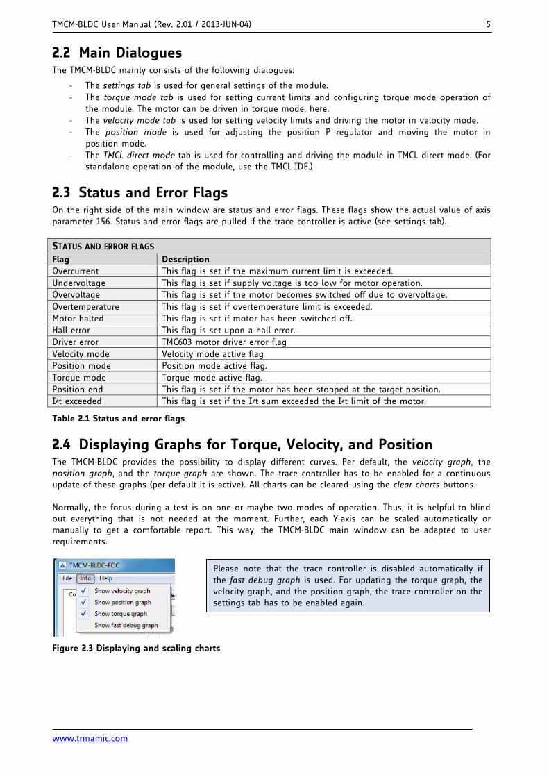
2.4 Displaying Graphs for Torque, Velocity, and Position The TMCM-BLDC provides the possibility to display different curves. Per default, the velocity graph, the position graph, and the torque graph are shown. The trace controller has to be enabled for a continuous update of these graphs (per default it is active). All charts can be cleared using the clear charts buttons. Normally, the focus during a test is on one or maybe two modes of operation. Thus, it is helpful to blind out everything that is not needed at the moment. Further, each Y-axis can be scaled automatically or manually to get a comfortable report. This way, the TMCM-BLDC main window can be adapted to user requirements.
Figure 2.3 Displaying and scaling charts
Please note that the trace controller is disabled automatically if the fast debug graph is used. For updating the torque graph, the velocity graph, and the position graph, the trace controller on the settings tab has to be enabled again.
TMCM-BLDC User Manual (Rev. 2.01 / 2013-JUN-04) 6
www.trinamic.com
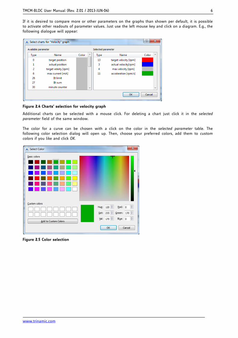
If it is desired to compare more or other parameters on the graphs than shown per default, it is possible to activate other readouts of parameter values. Just use the left mouse key and click on a diagram. E.g., the following dialogue will appear:
Figure 2.4 Charts’ selection for velocity graph
Additional charts can be selected with a mouse click. For deleting a chart just click it in the selected parameter field of the same window. The color for a curve can be chosen with a click on the color in the selected parameter table. The following color selection dialog will open up. Then, choose your preferred colors, add them to custom colors if you like and click OK.
Figure 2.5 Color selection
TMCM-BLDC User Manual (Rev. 2.01 / 2013-JUN-04) 7
www.trinamic.com
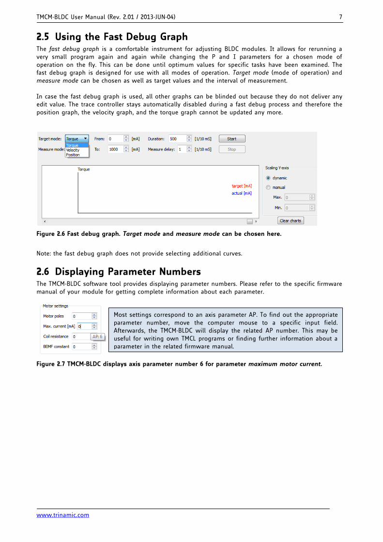
2.5 Using the Fast Debug Graph The fast debug graph is a comfortable instrument for adjusting BLDC modules. It allows for rerunning a very small program again and again while changing the P and I parameters for a chosen mode of operation on the fly. This can be done until optimum values for specific tasks have been examined. The fast debug graph is designed for use with all modes of operation. Target mode (mode of operation) and measure mode can be chosen as well as target values and the interval of measurement. In case the fast debug graph is used, all other graphs can be blinded out because they do not deliver any edit value. The trace controller stays automatically disabled during a fast debug process and therefore the position graph, the velocity graph, and the torque graph cannot be updated any more.
Figure 2.6 Fast debug graph. Target mode and measure mode can be chosen here.
Note: the fast debug graph does not provide selecting additional curves.
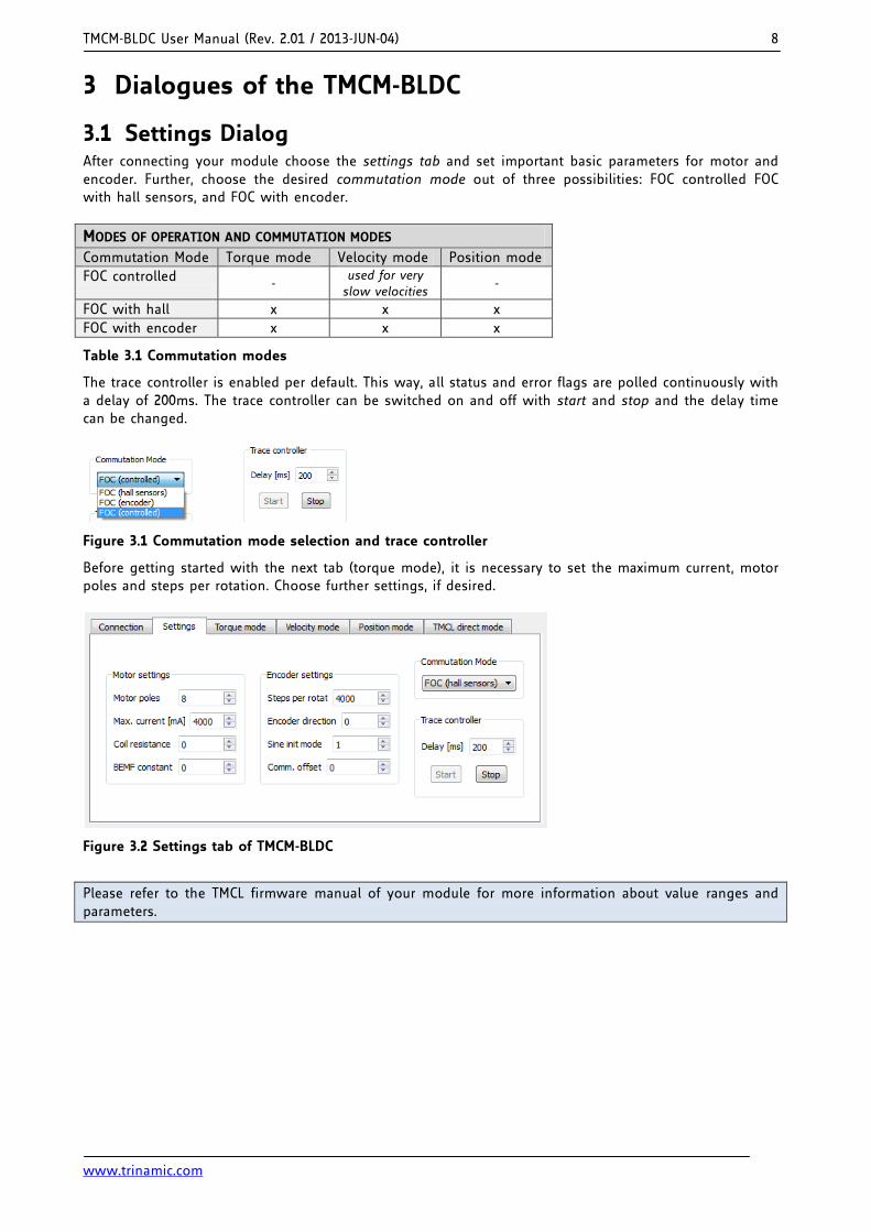
2.6 Displaying Parameter Numbers The TMCM-BLDC software tool provides displaying parameter numbers. Please refer to the specific firmware manual of your module for getting complete information about each parameter.
Figure 2.7 TMCM-BLDC displays axis parameter number 6 for parameter maximum motor current.
Most settings correspond to an axis parameter AP. To find out the appropriate parameter number, move the computer mouse to a specific input field. Afterwards, the TMCM-BLDC will display the related AP number. This may be useful for writing own TMCL programs or finding further information about a parameter in the related firmware manual.
TMCM-BLDC User Manual (Rev. 2.01 / 2013-JUN-04) 8
www.trinamic.com
3 Dialogues of the TMCM-BLDC
3.1 Settings Dialog After connecting your module choose the settings tab and set important basic parameters for motor and encoder. Further, choose the desired commutation mode out of three possibilities: FOC controlled FOC with hall sensors, and FOC with encoder.
MODES OF OPERATION AND COMMUTATION MODES
Commutation Mode Torque mode Velocity mode Position mode
FOC controlled - used for very slow velocities
-
FOC with hall x x x
FOC with encoder x x x
Table 3.1 Commutation modes
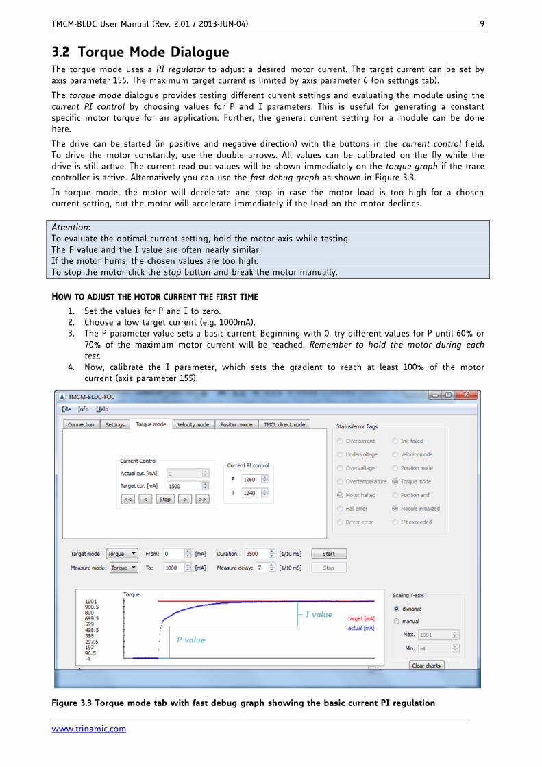
The trace controller is enabled per default. This way, all status and error flags are polled continuously with a delay of 200ms. The trace controller can be switched on and off with start and stop and the delay time can be changed.
Figure 3.1 Commutation mode selection and trace controller
Before getting started with the next tab (torque mode), it is necessary to set the maximum current, motor poles and steps per rotation. Choose further settings, if desired.
Figure 3.2 Settings tab of TMCM-BLDC
Please refer to the TMCL firmware manual of your module for more information about value ranges and parameters.
TMCM-BLDC User Manual (Rev. 2.01 / 2013-JUN-04) 9
www.trinamic.com
3.2 Torque Mode Dialogue The torque mode uses a PI regulator to adjust a desired motor current. The target current can be set by axis parameter 155. The maximum target current is limited by axis parameter 6 (on settings tab).
The torque mode dialogue provides testing different current settings and evaluating the module using the current PI control by choosing values for P and I parameters. This is useful for generating a constant specific motor torque for an application. Further, the general current setting for a module can be done here.
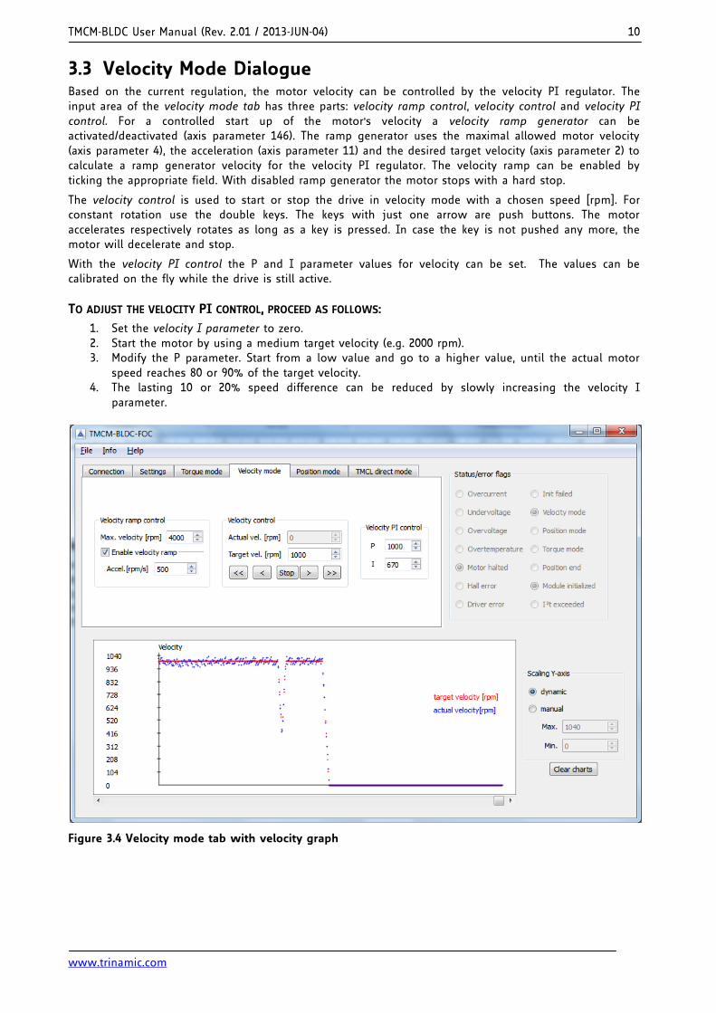
The drive can be started (in positive and negative direction) with the buttons in the current control field. To drive the motor constantly, use the double arrows. All values can be calibrated on the fly while the drive is still active. The current read out values will be shown immediately on the torque graph if the trace controller is active. Alternatively you can use the fast debug graph as shown in Figure 3.3.
In torque mode, the motor will decelerate and stop in case the motor load is too high for a chosen current setting, but the motor will accelerate immediately if the load on the motor declines.
Attention: To evaluate the optimal current setting, hold the motor axis while testing. The P value and the I value are often nearly similar. If the motor hums, the chosen values are too high. To stop the motor click the stop button and break the motor manually.
HOW TO ADJUST THE MOTOR CURRENT THE FIRST TIME
1. Set the values for P and I to zero. 2. Choose a low target current (e.g. 1000mA). 3. The P parameter value sets a basic current. Beginning with 0, try different values for P until 60% or
70% of the maximum motor current will be reached. Remember to hold the motor during each test.
4. Now, calibrate the I parameter, which sets the gradient to reach at least 100% of the motor current (axis parameter 155).
P value
I value
Figure 3.3 Torque mode tab with fast debug graph showing the basic current PI regulation
TMCM-BLDC User Manual (Rev. 2.01 / 2013-JUN-04) 10
www.trinamic.com
3.3 Velocity Mode Dialogue Based on the current regulation, the motor velocity can be controlled by the velocity PI regulator. The input area of the velocity mode tab has three parts: velocity ramp control, velocity control and velocity PI control. For a controlled start up of the motor's velocity a velocity ramp generator can be activated/deactivated (axis parameter 146). The ramp generator uses the maximal allowed motor velocity (axis parameter 4), the acceleration (axis parameter 11) and the desired target velocity (axis parameter 2) to calculate a ramp generator velocity for the velocity PI regulator. The velocity ramp can be enabled by ticking the appropriate field. With disabled ramp generator the motor stops with a hard stop.
The velocity control is used to start or stop the drive in velocity mode with a chosen speed [rpm]. For constant rotation use the double keys. The keys with just one arrow are push buttons. The motor accelerates respectively rotates as long as a key is pressed. In case the key is not pushed any more, the motor will decelerate and stop.
With the velocity PI control the P and I parameter values for velocity can be set. The values can be calibrated on the fly while the drive is still active.
TO ADJUST THE VELOCITY PI CONTROL, PROCEED AS FOLLOWS:
1. Set the velocity I parameter to zero. 2. Start the motor by using a medium target velocity (e.g. 2000 rpm). 3. Modify the P parameter. Start from a low value and go to a higher value, until the actual motor
speed reaches 80 or 90% of the target velocity. 4. The lasting 10 or 20% speed difference can be reduced by slowly increasing the velocity I
parameter.
Figure 3.4 Velocity mode tab with velocity graph
TMCM-BLDC User Manual (Rev. 2.01 / 2013-JUN-04) 11
www.trinamic.com
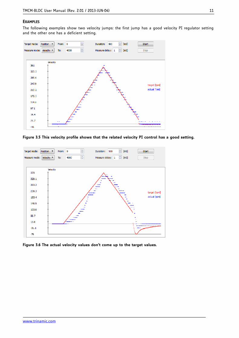
EXAMPLES
The following examples show two velocity jumps: the first jump has a good velocity PI regulator setting and the other one has a deficient setting.
Figure 3.5 This velocity profile shows that the related velocity PI control has a good setting.
Figure 3.6 The actual velocity values don’t come up to the target values.
TMCM-BLDC User Manual (Rev. 2.01 / 2013-JUN-04) 12
www.trinamic.com
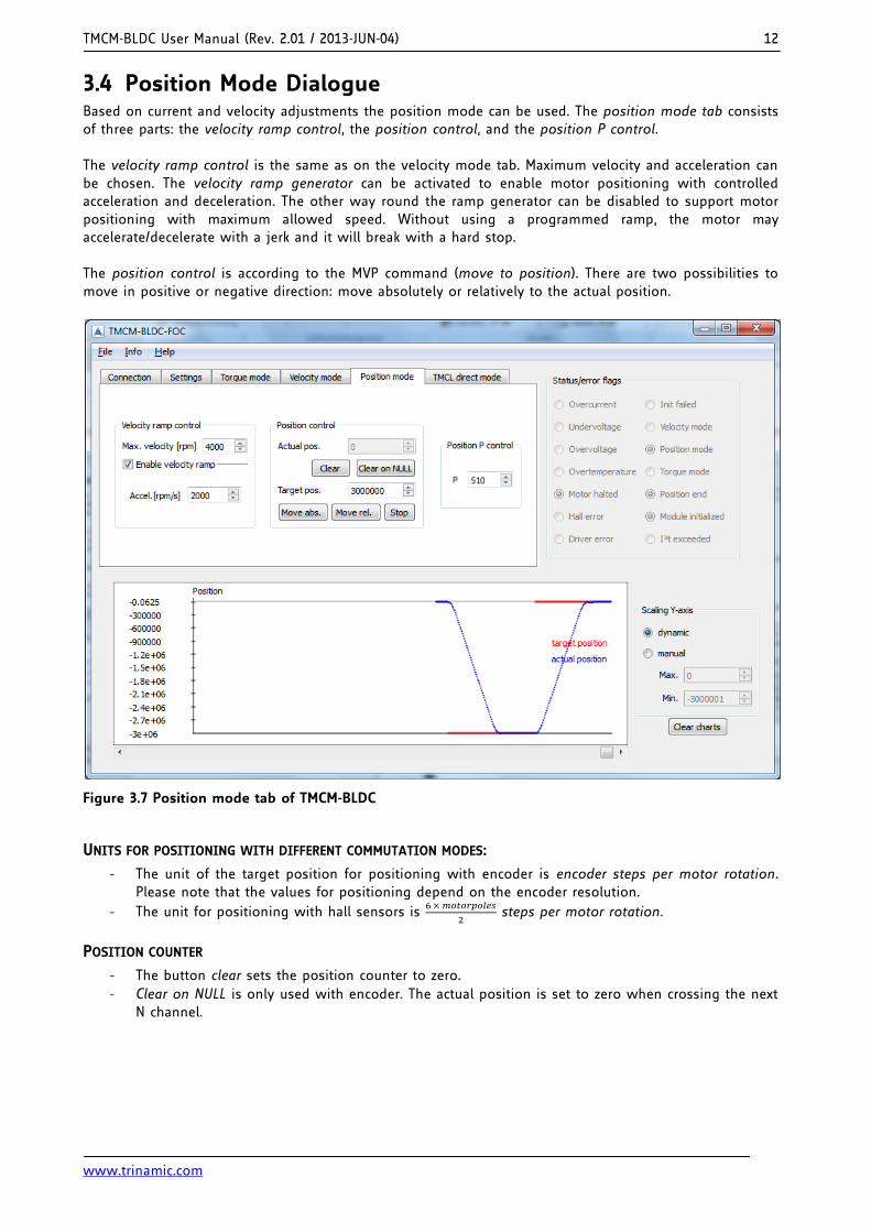
3.4 Position Mode Dialogue Based on current and velocity adjustments the position mode can be used. The position mode tab consists of three parts: the velocity ramp control, the position control, and the position P control. The velocity ramp control is the same as on the velocity mode tab. Maximum velocity and acceleration can be chosen. The velocity ramp generator can be activated to enable motor positioning with controlled acceleration and deceleration. The other way round the ramp generator can be disabled to support motor positioning with maximum allowed speed. Without using a programmed ramp, the motor may accelerate/decelerate with a jerk and it will break with a hard stop. The position control is according to the MVP command (move to position). There are two possibilities to move in positive or negative direction: move absolutely or relatively to the actual position.
Figure 3.7 Position mode tab of TMCM-BLDC
UNITS FOR POSITIONING WITH DIFFERENT COMMUTATION MODES:
- The unit of the target position for positioning with encoder is encoder steps per motor rotation. Please note that the values for positioning depend on the encoder resolution.
- The unit for positioning with hall sensors is
steps per motor rotation.
POSITION COUNTER
- The button clear sets the position counter to zero.
- Clear on NULL is only used with encoder. The actual position is set to zero when crossing the next N channel.
TMCM-BLDC User Manual (Rev. 2.01 / 2013-JUN-04) 13
www.trinamic.com
PARAMETERIZING THE POSITION REGULATION
1. Disable the velocity ramp generator and set the position P parameter to zero. 2. Choose a target position and increase the position P parameter until the motor reaches the target
position approximately. 3. Switch on the velocity ramp generator. Based on the maximum positioning velocity (axis
parameter 4) and the acceleration value (axis parameter 11) the ramp generator automatically calculates the slow down point, i.e. the point at which the velocity has to be reduced in order to stop at the desired target position.
4. Reaching the target position is signaled by automatic setting of the position end flag.
The P parameter has to be set in a way that the motor keeps a position even if the load on the motor forces it forwards. Therefore, just turn the motor axis by hand a bit in one direction and check if the axis has too much play. In position mode, the motor has to return immediately to the position it has to keep. To ensure this, it may be necessary to increase the value for P.
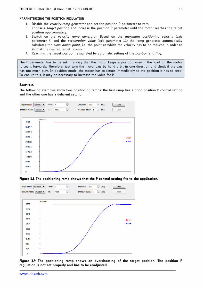
EXAMPLES
The following examples show two positioning ramps: the first ramp has a good position P control setting and the other one has a deficient setting.
Figure 3.8 The positioning ramp shows that the P control setting fits to the application.
Figure 3.9 The positioning ramp shows an overshooting of the target position. The position P regulation is not set properly and has to be readjusted.
TMCM-BLDC User Manual (Rev. 2.01 / 2013-JUN-04) 14
www.trinamic.com
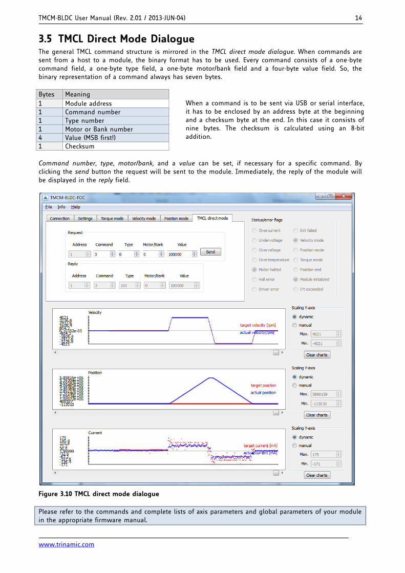
3.5 TMCL Direct Mode Dialogue The general TMCL command structure is mirrored in the TMCL direct mode dialogue. When commands are sent from a host to a module, the binary format has to be used. Every command consists of a one-byte command field, a one-byte type field, a one-byte motor/bank field and a four-byte value field. So, the binary representation of a command always has seven bytes.
Bytes Meaning
1 Module address
1 Command number
1 Type number
1 Motor or Bank number
4 Value (MSB first!)
1 Checksum
Command number, type, motor/bank, and a value can be set, if necessary for a specific command. By clicking the send button the request will be sent to the module. Immediately, the reply of the module will be displayed in the reply field.
Figure 3.10 TMCL direct mode dialogue
Please refer to the commands and complete lists of axis parameters and global parameters of your module in the appropriate firmware manual.
When a command is to be sent via USB or serial interface, it has to be enclosed by an address byte at the beginning and a checksum byte at the end. In this case it consists of nine bytes. The checksum is calculated using an 8-bit addition.
TMCM-BLDC User Manual (Rev. 2.01 / 2013-JUN-04) 15
www.trinamic.com
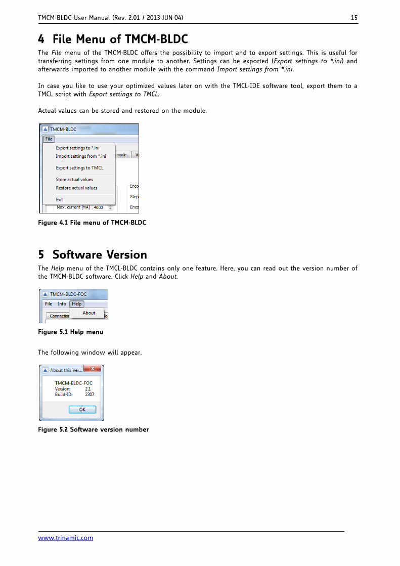
4 File Menu of TMCM-BLDC The File menu of the TMCM-BLDC offers the possibility to import and to export settings. This is useful for transferring settings from one module to another. Settings can be exported (Export settings to *.ini) and afterwards imported to another module with the command Import settings from *.ini. In case you like to use your optimized values later on with the TMCL-IDE software tool, export them to a TMCL script with Export settings to TMCL. Actual values can be stored and restored on the module.
Figure 4.1 File menu of TMCM-BLDC
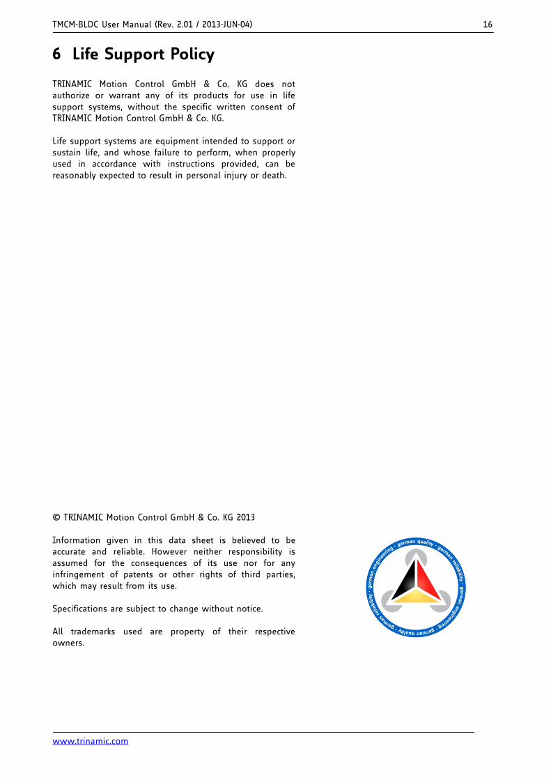
5 Software Version The Help menu of the TMCL-BLDC contains only one feature. Here, you can read out the version number of the TMCM-BLDC software. Click Help and About.
Figure 5.1 Help menu
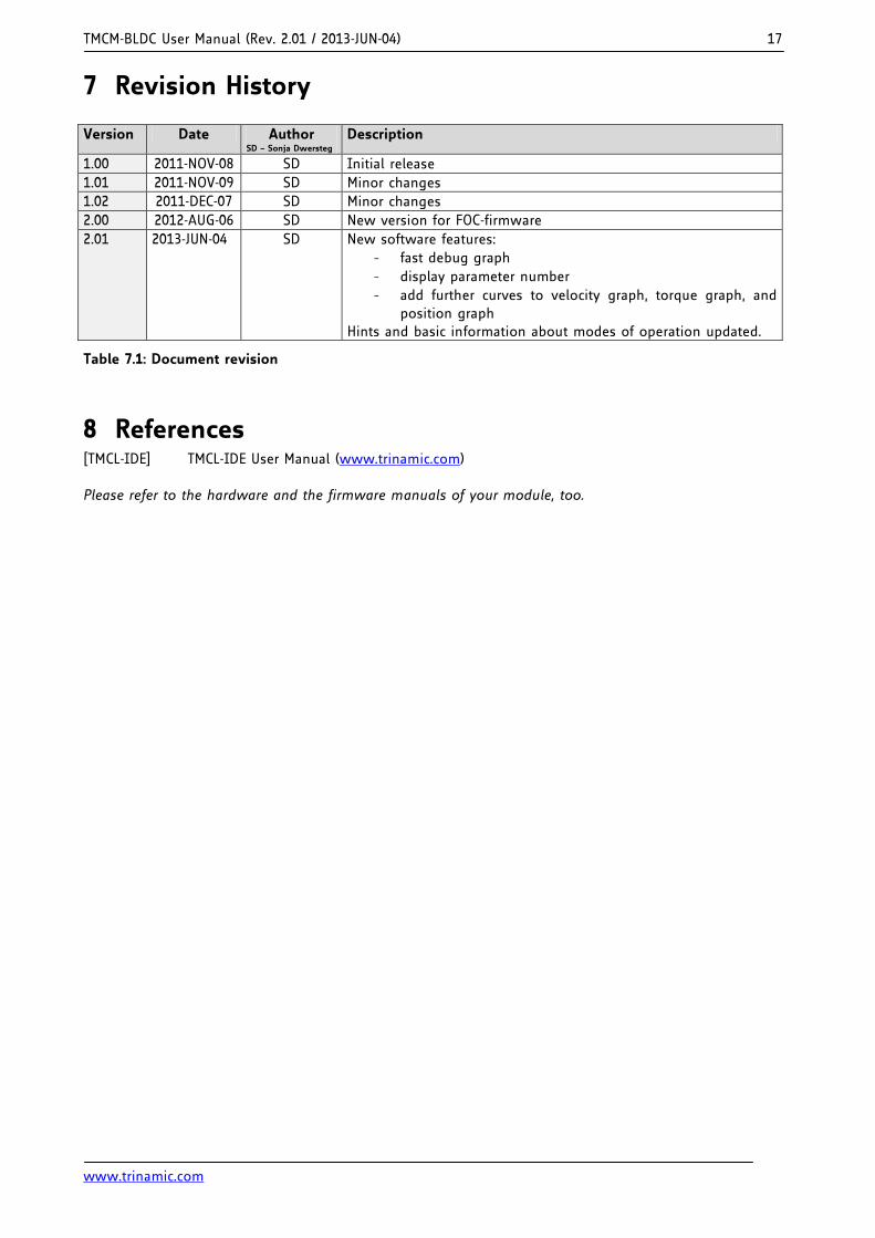
The following window will appear.
Figure 5.2 Software version number
TMCM-BLDC User Manual (Rev. 2.01 / 2013-JUN-04) 16
www.trinamic.com
6 Life Support Policy TRINAMIC Motion Control GmbH & Co. KG does not authorize or warrant any of its products for use in life support systems, without the specific written consent of TRINAMIC Motion Control GmbH & Co. KG. Life support systems are equipment intended to support or sustain life, and whose failure to perform, when properly used in accordance with instructions provided, can be reasonably expected to result in personal injury or death. © TRINAMIC Motion Control GmbH & Co. KG 2013 Information given in this data sheet is believed to be accurate and reliable. However neither responsibility is assumed for the consequences of its use nor for any infringement of patents or other rights of third parties, which may result from its use. Specifications are subject to change without notice. All trademarks used are property of their respective owners.
TMCM-BLDC User Manual (Rev. 2.01 / 2013-JUN-04) 17
www.trinamic.com
7 Revision History
Version Date Author SD – Sonja Dwersteg
Description
1.00 2011-NOV-08 SD Initial release
1.01 2011-NOV-09 SD Minor changes
1.02 2011-DEC-07 SD Minor changes
2.00 2012-AUG-06 SD New version for FOC-firmware
2.01 2013-JUN-04 SD New software features:
- fast debug graph
- display parameter number
- add further curves to velocity graph, torque graph, and position graph
Hints and basic information about modes of operation updated.
Table 7.1: Document revision
8 References [TMCL-IDE] TMCL-IDE User Manual (www.trinamic.com) Please refer to the hardware and the firmware manuals of your module, too.