Embed Size (px)
Citation preview
Contek Comments
Slowdown vent stacks are not currently listed in Natural Gas Production
Emission Source Type
PneumaticHigh BI~d Device Venting
Pneumatic lOw Bleed Device Venting
Pneumatic PumpVenung
Acid Gas Removal Vents
Dehy Vent Stacks (Without vapor recovery or
thermal control)
Well Venting for liquids Unloading
Gas Well Venting for Unconventional
CompletionslWorkovers
Gas WelJ Venting for Conventional
CompletionSJWQrkovers
Slowaa"'/fi Vent Stacl~s
Storage Tanks
Well Testing Venting
~ Associated Gas Venting
Calculation Approach
mfr data & analysis (analyzer or sampling)
default emission facta~
mfr data & analysis (analyzer or sampling)
mass balance & analysis (analyzer or sampling)
Simulation - Glycalc
Measurement & analysis (analyzer or sampling)
Measurement & analysis (analyzer or sampling)
Measurement & analysis (analyzer or sampling)
Simulation - E&P Tank
Calculation & analysis (analyzer or sampling)
Calculation & analysis (analyzer or sampling)
Leak Detection Required (Le.IR)
not required
not required
110t required
Emissions Calculated/Reported
Volumetric natural gas and CO,tCH. (Volumetric and Mass)
Total Mass C02e
Mass CO,lCH4
Total Mass CO,s
Volumetric natural gas and CO,lCH. (Volumetric and Mass)
Volumetric CO,
Total Mass C02e
Volumetric and Mass CO,lC H.
Total Mass C02e
Volumetric natural gas and CO,lCH4 (Volumetric and Mass)
Total Mass COze
Volumetric natural gas and CO,lCH. (Volumetric and Mass)
T otai Mass COze
Volumetric natural gas and CO,lCH, (Volumetric and Mass)
Volumetric flatl/Fal gas ana GG;,!GM. (Veil/metric anEi Mass)
Volumetric natural gas and CO,tCH4 (Volumetric and Mass)
Total Mass COze
Volumetric natural gas and CO,lCH4 (Volumetric and Mass)
Total Mass CO,e
Data Collection/Programming Requirements
Annual Minutes ~ (In operation through reporting period)
D!>vice Count and GHG Concentration
Annual Volume of liquid Pumped (must be logged per individual pump)
Metered Natural Gas Flow and Percent CO2 (inlout)
Ambient lemperalures and pressures
GlyCalc
Annual Hours Vented and Tubing DiameterlWell-field Specific Emission
Factor Ambient temperatures and pressures
OR Well Specific Calculation Including:
Casing diameter Well depth
Shul-in pressure Vent Log
Sales flow rate Hours of unloading
Annual Hours Vented and Venting Flow Rate
Ambient temperatures and pressures
Daily Gas Production Rate (cfm) and Annual Hours Vented
Ambient temperatures and pressures
NumBer at Blewdewfls ~er year (must Be legged) Tetal Volume af SlaV/down E~uiJlment
GOR BPD Flow Rate
Ambient temperatures and pressures
GOR Barrels per Year Produced Oil
Ambient temperatures and pressures
Other
Annual average Mole % from continuous analyzeror quarterly analysis
Manufacturer's bleed rate
Emission factors provided in Tables W-1, W-3,andW-4 (Population factors)
Manufacturer's emission per volume Of liquid (at specific operating pressure)
Annual average Mole % from continuous analyzer or quarterly analysis
Annual average Mole % from continuous analyzer or quarterly analysis
Method 1: Can use stats as long as in same field and tubing size
Annual average Mole % from continuous analyzer or quarterly analysis
Annual average Mole % from continuous analyzer or quarterly analysis
Annual average Mole % from continuous analyzer or quarterly analysis
Annual average Mole % from continuous analyzer or quarterly analYSis
Annual average Mole % from continuous analyzer or quarterly analysis
Emissions Equation
E=B'T
Mass =Count' EF ~ GHG Cone' Conv • 24 * 365
E=F*V
E" (V, • %Vol,) - (V,' %Vol,)
E=T'FR OR
E=[ (O.37xW") • CO2 , WD ' SP * V) + (SFR ' HR)]
E =T' FR
E=V'T
E=GOR'FR'D
E=GOR 'V
Contek Changes/Additions
Es,n = B~" * T (Volume of gas at std conditions)
E", =E", 'M, (Volume of CO, or CH, at std, conditions)
Mass", = E", , Density' GWP' 10-' (CO,e mass of CO, or CH,)
E,n, " F, • V (Volume of gas at std, conditions)
E3.1 =E s.n "MI (Volume of COL or CH 4 at std. conditions)
E'i.GO~~::;:: (V1 '" %VoU - (V:' k %VoI2) (Volume of CO:: at ambient conditions)
El>,I::; (E,'lC02 1; (460 + T J *" Pa)/«(460 + TaJ ;, Ps) (Volume of CO::: at std, conditions)
Mass'S} :: EsJ ~. Density 0: GWP ~. 10-3 (CO~e- mass of CO~)
METHOD 1: Ea,n:: T '" FR (Volume of gas at ambient conditions)
E':;,f);::; (E;;.r:" (460 + TsJ" P~)/((460 + T"J '" Ps) (Volume of gas at std. conditions)
E.;,J =Es.n .. M (Volume of CO~ or CH 4 at std. condifions)
METHOD 2: E",,=[ (O,37x10~'1) 'CD2
" WD "SP "V)] + (SFR 'HR) (Volume of gas at standard conditions)
Es,1 =ES.11 /, Mj (Volume of CO:;;. or CH4 at standard conditions)
Mass'S.! ::; Es.J " Density'" GVVP '" 10-3 (C 02e mass of CO2 or C H4)
E'l,n - T ~ FR (Volume of gas at ambient conditions)
Es,i"):: (E<ln" (460 + Ts)'" P3 )!((460 + Ta)"" P5-J (Volume of gas at std. conditions)
Es.l ::E~,n '" MI {Volume of CO~!, or CH . .j at std, conditions)
E;,;"l - V '* T (Volume of gas at ambient conditions)
Es,[\:: (E;;.n ~ (460 + T(;)'~ Pa)J((460 + Tal f( p,J (Vo!ume of gas at std. conditions)
Es,1 z::ESiL ." M, (Volume of CO;: or CH 4 at std. conditions)
Mass", = E" " Density" GWP " 10" (COoe masS of CO2)
E;;!Jl GOR * FR ~ 0 (Volume of gas at ambient conditions)
E", = (E"c '(~60 + T,) " P ,)1((460 + T,) • P ,) (Volume of gas at std, conditions)
E~,l =E,,>.n ..,. Mi (Volume of CO2 or CH4 at std, conditions)
Ea,i] - GOR .., V (Volume of gas at ambient conditlons)
ES(l:: (E,,11 1< (460 + TJ 1< P~)/((460 + T"J '" P.;,) (Volume of gas at std, conditions)
Es,l =Es,)1 *" MI (Volume of CO2 Dr CH." at std conditions)

E,,; (uncombListed) ~ V,' (1-~)' x, Flare Stacks Volumetric natural gas and E"co2(combusted) ~ I ~ 'V, * Y, * R,
(Also used for flared emissions CO,lCH. (Volumetric and Mass) Dependent E(uncombust) =V'(1-T)*X Ea)totai) ;:: E,'liuncombusted) + Ea.,(combusted)
from dehy vent stacks, storage Calculation 8. analysis (analyzer or N20 calculated using emission factors E(combusted) = I T)'V "Y' Rtanks, welf testing, associated sampling) Total Mass CO,8
Ambient temperatures and pressures for gas fiares, Table W-a E(total) = E(uncombust) +E(combusted) E,,;;:: (EIi.i k (460'" TJ * P,,)!((460 + T'l) '/< Ps ) (VOlume of GHG, at std, conditions) gas venting, and degassing
vent vapors) N,O Emissions Mass\l.l =. ES,i .~ Density'" GWP ." 10-3 (CO::8 mass of CO2)
Volumetric CO,lCH. (Volumetric Measured Gas Flow to Vent E",- MT'T'M:(1-B)
Centrifugal Compressor Wet Measurement & analysis (analyzer not required
and Mass) Operational time log
Annua! average Mole % from continuous E= MT'T'M " (1-B) E,,; = (E,,' (460 + T,)' PJi«(460 + T,)' P,) (Volume of GHG, at std, conditions) Seal Degassing Vents or sampling) VRU operating log (if applicable)
analyzer or quarterly analysis Total Mass COoe
% used for fuel gas (if applicable) Masss i :z:; Es,1 k Density'" GWP ~ 10-3 (CO,s mass of CO,)
Measured Gas Flow to Vent Ea: =MT*T*M "i",,,melanses Volumetric COiCH. (Volumetric
Operational time log No deminlmus HP
Reciprocating Compressor Rod Measurement & analysis (analyzer Uncsrtain about and Mass) OR E= MT *T" M" (1-B) E,,; = (E", * (460 + T,)' P)/((460 + T,) * p,) (Volume of GHG, at std, conditions)
Packing Venting or sampllng) compressors for production Annual Leak Detection via Optical Monitoring and
Annual average Mole % from continuous submitted queslian to EPA Total Mass CO,e analyzer or quarterly analysiS MassS.i = Es" -k Density'" G'vVP .,. 1U·~Do not believe this will be Measurement for Leakers (CO"e mass of CO,)
Fugitives Annual hours of operation: EmiSSians,calculatedJor Emission factors provided In Tables W-1Population emiSSion factors ~ Volumetric CO,lCH. (Volumetric pneumatic low bleed device venting, gathering E"I = Count * EF *GHG, * T (Volume of CO" or CH, at sid, conditions)
opticalleak detection not Measurement >l uRae, seRalA and Mass) pipelin~ fugitives, coal bed methane produced water through W-7
(Population factors) E = Count" EF • GHG * T required Analysis ??? si,s"",slaAses emissions and fugitive emissionsfrom valves, _ Mass~.i = E""I * Density" GV';P ". 10. 3 (C02e mass of CO,: 01' CH,)
(For strearnswith gas oontent Total Mass COze oonnectors, open ended lines, prassure relief valves, Concentration of GHG,>10%)- comoressoi startoes vants, Dumas fiandes and Hydrocar!:lOn (HC) Liquids ~
Analysis Total Mass C02e Quarierly Sampling to Determine Relention of CO2 in Mass = S·V Mass~"co: = Sh1 '" Vl>l Dissolved CO2 HC Liquids
ProducedWater- Dissolved Analysis Total Mass C02s Quarterly sampling to deterimene retention of CO2 in Mass = S'V Mass5.C02 ;::: Spw ~'Vpw
CO2 , produced water Portable Equipmenl - Total Mass C02e Annual Quantity of Fuel Combustad Subpart C, Tier 1 - Default values
-
Subpart C, Tier 1 Combustion EmiSSions
Measurement or Operating hours "
CO2 Captured and Tt'!lnsferred Measurement
Metered Quantity of CO2 TranSferred (reoorded Subplilrt PP MethodologyOffsite quarterly)
~IT~[Jn-------------------=- !:t;,twrlln &rt';.iJlltiJl(~Lm:i1
Hand Delivery
MEMORANDUM
TO: Administrator Cass R. Sunstein White House Office ofInformation and Regulatory Affairs
FROM: Grover R. Campbell Chairman, Air Subcommittee
DATE: September 29,2010
RE: EP A's Mandatory Greenhouse Gas Reporting Rule, Subpart W
The American Exploration & Production Council ("AXPC") thanks you for the opportunity to meet with you and your staff at the Office of Information and Regulatory Affairs on September 29,2010, to discuss elements of EPA's proposed Mandatory Greenhouse Gas Reporting Rule.
Subpart W of EPA's proposed rule addresses GHG emissions from petroleum and natural gas systems. l AXPC is a national trade association representing 25 of the largest United States independent natural gas and crude traded corporations. AXPC members are leaders in developing and applying technology necessary to explore for and extract oil and gas onshore and offshore, including in deep water and from unconventional reservoirs. AXPC's members are among the most active in drilling natural gas and oil exploration and development wells in the United States, accounting for nearly one quarter of all wells drilled.
AXPC would like to highlight three points concerning the proposed Subpart W:
1. Substantially the same GHG inventory accuracy can be achieved at much less cost.
2. A tiered system covering upstream production would be practical and effective.
3. Emissions from portable equipment can be exempted without impairing the inventory.
1 7S Fed. Reg. 18,608 (Apr. 12,2010).
-~--'----"";;;;;;"- !:r.I(If".ti~n&ffrolrl'm
Page 2 ~rr~IiQn
(~l(1\(iI
Subpart W Imposes Disproportionate Compliance Costs with Minimal Added Accuracy.
The natural gas sector, a minor contributor to the national GHG inventory, should not be required to incur admittedly disproportionate costs to measure small-scale emissions across hundreds ofthousands ofindividual sources.
EPA's cost estimates for proposed Subpart Ware unreasonably low. AXPC and industry associations have prepared detailed analysis showing costs more than sixty (60) times EPA's estimates. 2
Even using EPA's estimates, and even though GHG emissions from Subpart W sources are a very small part of the national GHG inventory, Subpart W sources bear a disproportionate burden - $41,000 per covered entity versus $13,000 per entity cost under the GHG Inventory Rule as a whole.
Subpart W covers only 1.4% of nationwide GHG emissions yet would apply to 500,000750,000 sources in the natural gas sector.
Graduated Requirements Are Needed for Upstream Production Sites.
To strike the appropriate balance3 between data accuracy and cost, the rule should use a tiered structure that avoids imposing undue costs on the smallest sources.
Exempt individual well sites with de minimis GHG emissions: individual well sites producing <60 MSCFD natural gas and <5 BOPD condensate, and oil stripper wells producing <10 BOPD. These sources are numerous but typically contribute less than 1,000 tpy GHGs to the national inventory.
Allow individual well sites with <3,000 tpy GHG to calculate and report emissions based on the API Compendium, rather than direct measurement. The Compendium is regularly updated and peer reviewed by government agencies and NGOs, and it aids data comparability in the sector.
Require more rigorous calculations for individual well sites with projected emissions >3,000 tpy GHG, but with much less direct measurement mandates than proposed. The direct measurement mandates drive the cost burden skywards.
2 AXPC members Chesapeake Energy Corporation and El Paso Production Company individually submitted analyses to EPA on June 11, 20 I 0 as part of the public comment process on proposed Subpart W. Chesapeake's analysis was submitted as Confidential Business Information. 3 EPA has expressed its desire to maintain "an appropriate balance [in the GHG Inventory Rule] between data accuracy and cost." 74 Fed. Reg. 56,260, 56,280 (Oct. 30, 2009).
Page 3 ~m~rltJn
.....;;;........;;=;;;:.;;;:;;;..;;.; ......... _=;;;... flil'lwiillln &h:.atrriJf Cafrtil
Emissions From Non-Stationary, Portable Equipment Should Be Exempted.
Subpart W should be made consistent with other parts of the ORO Inventory Rule that exempt portable equipment, especially given the minor emissions involved and the limited data that natural gas producers have for equipment owned and operated by third parties.
The GHG Inventory Rule does not require reporting of emissions from comparable sources, like residential, commercial or roadway construction, and Subpart C exempts portable equipment, emergency generators, and emergency equipment.
Natural gas producers generally do not control the operation of third-party equipment and do not perform or schedule maintenance.
Contract service companies typically own this equipment and control the operational data needed to calculate GHG emissions accurately.
Most portable equipment is fired by diesel fuel, and these emISSIOns will already be reported by petroleum product suppliers under Subpart MM.
Natural Gas Star data allow a reasonable estimate of GHG emissions from this equipment. Those emissions estimates can be used with known well drilling and completion data to provide a reasonable emission estimate from these sources.
In conclusion, AXPC appreciates the opportunity to highlight for you the foregoing concerns and proposals with respect to EPA's proposed Subpart W rule. If you have any questions or would like clarification or further information, please call me at (405) 935-7543.
CONFlOENTlAL BUSINESS INFORMATION
Appendix A to Comments Filed by
Chesapeake Energy Corporation Regarding EPA's Proposed Rule for Mandatory Reporting of Greenhouse Gases: Petroleum and Natural Gas Systems;
75 Fed. Reg. 18,608 (Apr. 12,201Oi
A~ re-eJ, CONFlllENTlAL BUSINESS lNFORMATlON /' 0 l'( --h, ~.>t
- ----- 0 V) lJveb, I Appendix A contains Confidential Business information and is being submitted separately
from the rest of Chesapeake Energy Corporation's comments on Proposed Subpart W to the Mandatory Greenhouse Gas Reporting Rule, 75 Fed. Reg. 18,608 (Apr. 12, 2010), Docket fD No. EPA-HQ-OAR-2009-0923.
CONFIDENTiAL BUSINESS INFORMA'fION
Appendix Pt.: MRR Subpart W Compliance Cost IEstimate
Submitted! by: Chesapeake Energy Corporation
Prepared By: Zack Schaffer
Asset Manager - Gas Star Program
Docket In No. EPA-HQ-OAR-2009-0923 June 11, 2010
CONFIDENTIAL BUSINESS INFORMATION
Prepared By: Zack Schaffer Asset Manager - Gas Star Program
MRR Subpal't W Compliance Cost Estimate
Thc rc-proposed Subpart W of the Mandatory Greenhouse Gas Reporting Rule requires onshore producers of oil and natural gas to report fugitive and vcnted emissions if those emissions are greater than or equal to 25,000 tonnes ofCCh equivalent within a basin. EPA's estimate of first-year compliance costs for onshore producers is $24,000 per reporting unit. See Table W-IO, 75 Fed. Reg. at 18,629 (Apr. 12, 2010). Chesapeake Energy Corporation's ("Chesapeake's") op rations and environmental, health and safety staff developed a bottom-up compliance cost estimate to demonstrate the actual costs to the natural gas industry.
As proposed, SubpaJi W would require repoliing of 21 individual fugitive and venting emissions sources. The scope of this cost estimate covers many of those soW'ces, but is focused mainly 011 soW'ces commonly found in Chesapeake's actual operations.
Compliance Cost Estimate
Chesapeake selected one basin from the AAPG Geologic Provinces Code Map as an example basin. Several sites within that basin were visited to survey the reportable sources and the level of effort required to comply with proposed Subpart W. The representative basin that Chesapeake selected houses a large portion of Chesapeake's Midcontinent operations. With over 8,000 wells within the basin, it is apparent that Chesapeake wi ll cross the 25,000 t01l11e threshold and would be required report emissions under proposed Subpart W. Whi le Chesapeake acknowledges that the actual compliance costs within a given basin can range greatly depending on the equipment operated and levels of activity, Table 1 below detai ls the estimated compliaJJce cost for an individual reporting unit assuming all operations are subject to reporting.
Table I: E,timatL·(\ CllIUplillllCC Costs for Chesapeake's First Year of Opcratiuns
Chesapeake's Operations In a Representative Basin
Estimate of Sources Cost per Source Compliance Cost
Estimate Single-Well Pads 5,174 $1,495 $7,735,450 Single-Well Pads wino oil tank 2,990 $350 $1 046,425 Multi-Well Pads 50 $2,705 $135,250 Dehydrators 382 $288 $109825 Recips 368 $805 $296240 Completions 198 $4.050 $801,900 Workovers 66 $4.050 $268920 Workovers wino Irac and I lowback 598 $100 $59.760 Overhead 1 $2,583 $2,583 Total $10,456353
1
CONFIDENTIAL BUSINESS INFORMA nON
To develop the compliance cost estimate, the text of proposed Subpart W was reviewed with particular focus on 40 C.F.R. § 98.233: Calculating GHG Emissions and 40 C.F.R. § 98.236: Data Reporting Requirements. Tbese sections of the proposed regulations detail the levels or aggregation requ ired to calculate and repOlt emissions. While emissions would be aggregated and reported at the basin level tmder the proposed text of Subpart W, certain data would need to be collected at individual well sites and even at individual pieces of equipment. After reviewing the calculations and reporting requirements, the fo llowing sources were developed as the base units for collecting data:
., Single-well Pads (with and withont oil tanks) " Multi-we ll Pads o Glycol Dehydrators " Reciprocating Compressors " Completion Operations o Workover Operations
At each of these base units, different data points would need to be collected for reporting purposes under the proposed Subpart W.
Chesapeake's estimate of compliance costs was developed using estimates of labor rates, level of effort, and equipment rental costs based on discussion with various Chesapeake operations and EllS staff.
Description of SOUTce Categories
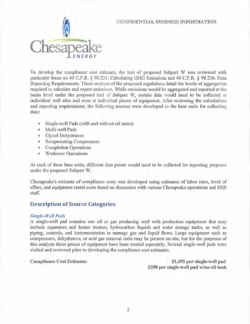
Single-Well Pllll~ A single-well pad contains one oil or gas produoing well with production equipment that may include separators and heater treaters, hydrocarbon liquids and water storage tanks, as well as piping, control s, and instrumentation to manage gas and liquid flows. Large equipment sllch as compressors, dehydrators, or acid gas removal units may be present on-site, but for the purposes of tllis analysis those pieces of equipment have been treated separately. Several single-well pads were visited and reviewed prior to developing the compljance cost estimates.
Compliance Cost Estimate: $1,495 per single-well pad $350 pcr Single-well pad wIno oil tank
2
CONFIDENTIAL BUSINESS INFORMATION
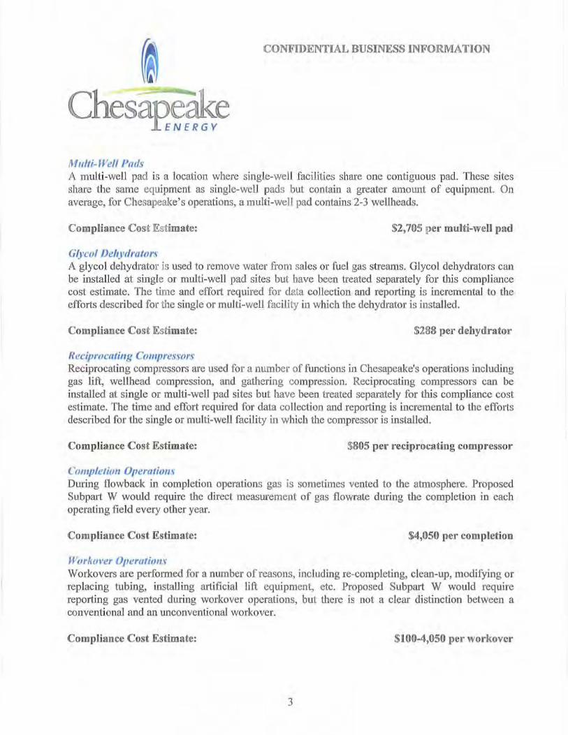
MIl/ii-Well Pads A multi-well pad is a location where single-well facilities share ooe contiguous pad. These sites share the same equipment as single-well pads but contain a greater amount of equipment. On average, for Chesapeake's operatioos, a multi-well pad contains 2-3 wellheads.
Compliance Cost Estimate: $2,705 per multi-well pad
GlyclIl Dehydrators A glycol dehydrator is used to remove water from sales or fuel gas streams. Glycol dehydrators can be installed at single or multi-well pad sites but have been treated separately for this compliance cost estimate. The time and effort req uired for data collectioo and reporting is incremental to tile efforts described for the single or multi-well facil ity in which the dehydrator is installed.
Compliance Cost Estimate: $288 per dehydrator
ReL"ipmCfltillg ClllllpreSfors Reciprocating compressors are used for a number of [unctions in Chesapeake's operations including gas lift, wellhead compression, and gathering compression. Reciprocating compressors can be installed at single or multi-well pad sites but have been treated separately for this compliance cost estimate. The time and effort required for data co llection and repOlting is incremental to the efforts described for the single or multi-well facility in which the compressor is installed.
Compliance Cost Estimate: $805 per reciprocating compressor
Cfllllplelilll/ Opel"(lliol/\ During llowback in completion operations gas is sometimes vented to the atmosphere. Proposed Subpalt W would require the direct measw·ement of gas flowrate during the completion in each operating fie ld every otller year.
Compliance Cost Estimate: $4,050 pel" completion
""rklll·er O{Jl!ralillll ~ Workovers are performed for a number of reasons, including re-completing, clean-up, modifying or replacing tubing, installing al1ificial lift equipment, etc. Proposed Subpart W would require reporting gas vented during workover operations, but there is not a clear distinction between a conventional and an unconventional workover.
Compliance Cost Estimate: $100-4,050 per workovcr
3
CONFIDENTIAL BUSINESS INFORMATION
O.'erhelul, QlIlllity COlltrol, IIntl Ref/llrtiug CII,vls To perform the proposed calculations on the data collected in the field and produce reports for EPA, Chesapeake would incur overhead costs to develop the IT systems and reports. Chesapeake is ahead of most of the industry in tenl1S of sophisticated data gatheling and repol1ing mechanisms, but the overhead costs associated with reporting w1der Subpart Ware not insignificant.
Compliance Cost Estimate: $50,000 Chesapeake-wide IT costs $500 per basin report
If you have any questions concerning Chesapeake's COOU11ents or require clarification, please contact me at (405) 935-7543.
Thank you for your consideration,
Grover R. Campbell Chesapeake Energy Corporation Manager - Corp. Air Regulations
4