Embed Size (px)
Citation preview

123
456
7
8
5
10
9a
9b
12
11
13
14
VBG 795V 2005-04-19 38-134800k
9a. Bar spacer washers 4 mm 9b. Bar spacer washer 10 mm 10. Bearing plate, outer 11. Rubber bearing12. Coupling jaw 13. Mechanism 14. Guiding funnel
1. Nut cover 2. Castellated nut 3. Split pin 4. Bearing plate, inner 5. Bolt kit 6. Rubber bearing 7. Drawbeam sleeve 8. Bushing
GeneralVBG 795 V, part no.: 09-052000The VBG 795V coupling is designed for centre axle trailers, full trailers with boggiefront axles and dollys that use a Ø 57.5 mm drawbar eye as per the VBG standard.The coupling should be mounted to a drawbeam which fulfi ls the requirements of ISO 3584 cat. 3. The web thick-ness in the middle of the drawbeam must be 13-30 mm with an inner clearance of at least 160 mm. It is easiest to mount it to a VBG drawbeam, all of which meet these requirements.The coupling has a high-quality corrosion resistance through electrolytic pre-treatment and a top-coat with very high wear resistance. To maintain the high quality of the surface treatment, VBG recommend that no futher paint is added to the coupling. If the coupling is over-painted, you run the risk of operational problems, a sticking signal/indicator pin or that important informa-tion is overpainted. Moving parts, plates anddecals must all be thoroughly covered if the coupling is repainted.
Identify all parts before installation. Installation shall be done in a proper and competent manner. Always follow the instructions.All directives and instructions should be kept in the vehicle for future service and maintenance.
ContentsMounting instructions ........................2
Safety check ......................................6
Service – maintenance ......................9
Driver instructions ...........................12
Spare parts list Power actuator .......16
Spare parts list VBG 795V ...............17

2
a
b
d
c
5–8,5 mm
Mounting instructions
• Lock the castellated nut with split pin. It is very impor-tant that the split pin is completely within the gatesof the castellated nut and is secured as per the pic-ture.• Lubricate the the castellated nut and the nut cover with grease.• Mount the nut cover.• When the coupling is reassembled after service, a new split pin must always be used.
Function checkCarry out the function check on page 5.
LubricationLubricate the coupling weekly with VBG mechanism oil or similar thin oil. For the maximum effect, the coupling should be open when it is being lubricated.VBG do not recommend the use of central greasing systems.
• Lubrication points (see adjacent drawing).
Mounting of drawbeam sleeve• Mount the drawbeam sleeve (a) with four screws as per the drawing. Flat washers with a minimum hardness of 200 HB must be under both bolt head and nut.Tightening torque M20 quality 8.8 (dry): 370 Nm.
Mounting of coupling• Lubricate the coupling jaw (b) and all its threads with grease. This prevents rust and makes future service work easier.• Fit the attachment parts as shown in the fi gure. Fit the bar spacer washers on the drawbeam sleeve collar so that the dimension 5–8,5 mm is achieved. The number of washers depends on the thickness of the drawbeam, and the 10 mm washer should be outermost. See fi gure. Mount accessories such as the coupling mouth exten-sion (c) according to the drawing.Tightening torque castellated nut 1500 – 2000 Nm.
Drawbeam sleeve
DrawbeamSpacers

3
f
i
ee
g
h
f
ca 5°
Mounting of a power actuatorIf the coupling is to be equipped with a power actuator, follow the directions below.
Mounting the power actuator on the coupling • Remove the two split pins (e) and the right hand bushing (f).
• Mount the adapter (g) on the hexagonal shaft and fi t with the roll pin (h) through the hole in the adapter.
• Tap the hexagonal shaft to the left and lock the hook on the adapter into the hook on the spring.
• Assemble the bushing (f) on the left side and refi t the split pin.• Remove the two screws on the right side of the mechanism (i).• Place the bracket and actuator on the coupling. Lock the bracket securely with the two long M12 screws which accompanied the power actuator unit.Tightening torque M12 quality 8.8 (dry): 90 Nm.
Mounting of the actuator on the bracket• Turn the shaft on the actuator clockwise until it can go no further and then turn it back approx. 5º.
• Bolt the actuator tightly onto the bracket with the four screws. Tightening torque M8 quality 8.8 (dry): 25 Nm.
4
Ø 6
Ø 8
4
Ø 6
21
Alt. A
Alt. B
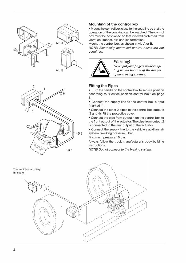
Mounting of the control box• Mount the control box close to the coupling so that the operation of the coupling can be watched. The control box must be positioned so that it is well protected from vibration, impact, dirt and ice formation.Mount the control box as shown in Alt. A or B.NOTE! Electrically controlled control boxes are not permitted.
Fitting the Pipes• Turn the handle on the control box to service position according to “Service position control box” on page 6.• Connect the supply line to the control box output (marked 1).• Connect the other 2 pipes to the control box outputs (2 and 4). Fit the protective cover.• Connect the pipe from output 4 on the control box to the front output of the actuator. The pipe from output 2 is connected to the rear output of the actuator.• Connect the supply line to the vehicle´s auxiliary air system. Working pressure 8 bar.Maximum pressure 10 bar.Always follow the truck manufacturer’s body building instructions.NOTE! Do not connect to the braking system.
The vehicle´s auxiliary air system
Warning!Never put your fi ngers in the coup-ling mouth because of the danger of them being crushed.

5
+
–
20
4060 80
100
120
approx 1 mm
BrownBlack
Blue
Inductivesensor
g
Signal
Signal: red and green lamp, (24 V max. 2 W)
Mounting of inductive sensor• Change the cover of the original lock indicator for the cover modifi ed for the inductive sensor. Open the coupling so that the indicator pin is out. Wind the induc-tive sensor in until it touches the indicator pin. Wind the inductive sensor back one turn (the distance between the indicator pin and the inductive sensor should now be approximately 1 mm).Tighten the nuts (g), tightening torque max. 2 Nm.
• If VBG’s Indicator kit (part no. 09-099200) is used – connect the inductive sensor according to the mounting instructions. Otherwise connect the inductive sensor to the vehicle’s electrical system (24 V). See wiring diagram above. Follow the truck manufacturer’s instructions.
• When the coupling is closed and secured a green lamp in the cab should light up.
• When the coupling is open, a red lamp in the cab should light up. If the green lamp comes on when the coupling is open, adjust the gap between the sensor and lock pin so that the red lamp comes on.

6
ab
c
a b
c
10 mm
a
• When the coupling is closed, there must be approx. 10 mm clearance in the handle before the indicator/ locking pin moves outwards.
Safety checkCarry out the safety check once a week. If the check shows that any of the wear limits have been exceeded or that the coupling´s function is reduced, rectifi cation must be carried out immediately.Before any work or service is carried out on the coupling all air supply to the coupling must be cut off. Cut off the air supply by turning the control box’ red handle a quarter turn anti-clockwise to OFF.
Function check• Check that the coupling bolt can be raised easily and that the handle and coupling bolt remain in the up position.• Open and close the coupling and check that it cor-responds as per the pictures below. If an inductive sensor is used, item (d) must be complied with.ALWAYS check that the coupling is closed and securebefore driving. All criteria for closed coupling must befulfi lled before you start driving.
Warning!Never put your fi ngers in the coup-ling mouth because of the danger of them being crushed.
If the coupling has been damaged as a result of jack-knifi ng, driving into a ditch, or being hit from be-hind, you must stop and replace the coupling.
Open coupling(a) The handle is raised approx. 90º(b) The indicator pin is out(c) The coupling bolt is up(d) Red lamp on in the cab
Closed, secure coupling(a) The handle is down(b) The indicator pin is completely in(c) The coupling bolt is down(d) Green lamp on in the cab
Service positionair supply off
Air supply on

7
A
B
Attachment• Check that the coupling can be rotated in its moun-ting. The coupling must be closed when the rotation is carried out.
Wear limitsA Coupling pin max Ø 55.0 mmB Drawbar eye max Ø 59.5 mmVertical playin the coupling bolt max 5.0 mm
LubricationLubricate the coupling weekly with VBG mechanism oil or similar thin oil. For maximum effect, the couplingshould be open when it is lubricated.
• Lubrication points (see drawing on the left)

8
Safety check contd.
e f
h
g
dOperation check - power actuator• Fold out the yellow handle (d). Simultaneously press on the mark “Press” on the handle and turn the handle anti-clockwise to “OPEN”. Then turn it back to “CLOSE”.The coupling pin should remain in the up/open posi-tion.
• Connect to the trailer according to the driver instruc-tions on page 14-15.
Air leaks• Check that there is no audible air leakage from the valve (e), the connection to the auxiliary air system (f), pipes (g) or actuator (h).
• In extreme cold, minor air leaks can occur. These can be eliminated by cutting off the air supply by turning the control box’s red handle (d) a quarter of a turn anti-clockwise to OFF.Contact the nearest workshop for corrective measu-res.
9
a
d
e
b c
CF
F
D
E
A
B
Service - maintenance
Change of mechanism and bushingsIf the coupling is equipped with a power actuator, the air supply to the control box must be cut off before work with the coupling is started.
• Remove the mechanism by loosening the four screws and lift the mechanism from the coupling jaw.
• Remove the wear plate.
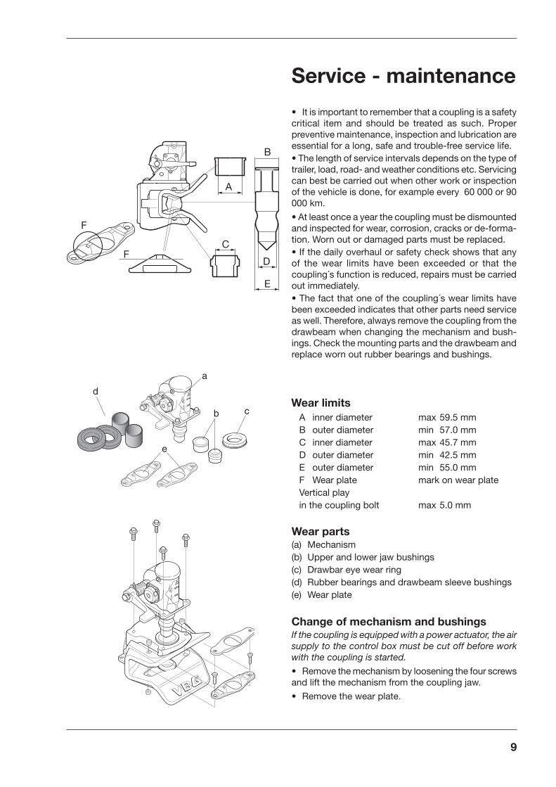
Wear parts(a) Mechanism (b) Upper and lower jaw bushings (c) Drawbar eye wear ring (d) Rubber bearings and drawbeam sleeve bushings (e) Wear plate
Wear limitsA inner diameter max 59.5 mmB outer diameter min 57.0 mmC inner diameter max 45.7 mmD outer diameter min 42.5 mmE outer diameter min 55.0 mmF Wear plate mark on wear plateVertical playin the coupling bolt max 5.0 mm
• It is important to remember that a coupling is a safety critical item and should be treated as such. Proper preventive maintenance, inspection and lubrication are essential for a long, safe and trouble-free service life.• The length of service intervals depends on the type of trailer, load, road- and weather conditions etc. Servicing can best be carried out when other work or inspection of the vehicle is done, for example every 60 000 or 90 000 km.
• At least once a year the coupling must be dismounted and inspected for wear, corrosion, cracks or de-forma-tion. Worn out or damaged parts must be replaced.• If the daily overhaul or safety check shows that any of the wear limits have been exceeded or that the coupling´s function is reduced, repairs must be carried out immediately.• The fact that one of the coupling´s wear limits have been exceeded indicates that other parts need service as well. Therefore, always remove the coupling from the drawbeam when changing the mechanism and bush-ings. Check the mounting parts and the drawbeam and replace worn out rubber bearings and bushings.

10
• Change the guide funnel if damaged. Minor damage and deformations on the funnel are accepted, the guide funnel is a seperate part from the coupling jaw and as long as the function is not reduced there is no need to replace the funnel.• Change the bushings using VBG service tools. Press out the old bushings from below and press in the new bushings from above as per the fi gure.The bushings must not be welded in.
Use tool no 9 as aguide in the lower jaw bushing.
Use tool no 12 as aguide in the upper jaw bushing. Place the tool on the bushing before as-sembly.
3
5a
13
2
2
9
12a
1010
• Mount the wear plate. Tightening torque 47 Nm.
• Put the new mechanism on the coupling jaw and fi t the screws, but do not tighten completely.
• Carry out the function check on page 6.
• Tighten the screws.Tightening torque M12 quality 8.8 (dry): 90 Nm.
RemovingLower jaw bushing
FittingLower jaw bushing
RemovingUpper jaw bushing
FittingUpper jaw bushing
Service – maintenance contd.

11
i
j
k
l
F
G
h
Lubricate the coupling with VBG mechanism oil. For maximum effect, the coupling must be open when it is being lubricated.
• Lubrication points (see drawing on the left)
Attachment check• Remove the coupling jaw and clean the shaft of rust and rubber residue.• Check that the coupling jaw is neither bent, nor has cracks or any damage due to electrolysis.• Check the wear limits as per below:
F max. Ø 67.2 mm (without bushings)G min. Ø 61.6 mm
Change of Indicator/locking pin• Loosen the three bolts holding the lid.• Remove remaining parts.• Clean the bearing surfaces for the locking pin (k) and lubricate with thin grease. Check that the centring pin (l) is correctly fi tted.• Mount the parts according to the fi gure.
• Check that there is no cracks forming or deformation on the drawbeam (i) and that the drawbeam sleeve (j) is properly attached.Tightening torque M20 quality 8.8 (dry): 370 Nm.

12
1
2
Driver instructions
Warning!Never put your fi ngers into the coup-ling mouth because of the danger of them being crushed.
Uncouple the trailer. The coupling is closed when the trailer is dis-connected.
Stand by the coupling handle.Lift the handle 90º, the handle locks. The coupling is now open.
Uncoupling without power actuator
For functional and road safety reasons, only those steps described in the Driver instructions may be carried out using the control box, power actuator, or air lines during coupling and uncoupling.If the coupling does not go to locked position after repeated attempts at coupling, the power actuator must be uncoupled immediately. Con-tact the nearest workshop for fault de-tection and remedial measures.

13
1
2
STOP
GO38-08100
4
6
5
0 mm ~10 mm
Check that the Indicator pin is completely in. If the Indicator pin is not completely in, the coupling is open and driving is not, under any circumstances, permitted!Contact nearest workshop for remedial measures.
Connect to the trailer.
Check that there is approx. 10 mm movement of the handle before the indicator pin moves outwards. If there is no free movement of the handle the coupling is open and driving is not, under any circum-stances, permitted! Contact nearest workshop for remedial measures.
The trailer is secured and driving can begin.
Stand by the coupling handle.Lift the handle 90º, the handle locks. The coupling is now open.
Coupling without power actuator

14
1 2
1
2
12
3
1+2
Simultaneously press on the handle where it says “Press” and turn the handle anti-clockwise to “OPEN”. Then turn it back to “CLOSE”.
Uncouple the trailer. The coupling is closed when the trailer is dis-connected.
Uncoupling
Before any work or service is carried out on the coupling all air supply to the coupling must be cut off. Cut off the air supply by turning the control box’ red handle a quarter turn anti-clockwise to OFF.
Warning!Never put your fi ngers into the coupling mouth because of the danger of them being crushed.

15
Coupling
1 2
1
2
3
4
12
3
1+2
GO
5
STOP
Simultaneously press on the handle where it says “Press” and turn the handle anti-clockwise to “OPEN”. Then turn it back to “CLOSE”.
If the red lamp comes on and the signal pin is not completely in, the coupling is open and the truck must under no circumstances be driven! Contact nearest workshop for remedial measures.
Couple to the trailer.
The trailer is secured and driving may begin.
Check that the signal pin goes fully in, and that the green warning lamp in the cab is on. The coupling is closed and secured, and the truck can now be driven.

AUSTRALIATRANSPEC LIMITEDP O Box 217 1 Cherry LaneAU - 3028 P.O LAVERTON, VIC 3028Tel +61 3 92 67 24 44Fax +61 3 93 69 48 26
BELGIUM/LUXEMBOURG WABCO Belgium S.A. - N.V.Petrus Bayensstraat 70BE – 1702 GROOT-BIJGAARDENTel +32 24810900Fax +32 24633659
DENMARKVBG PRODUKTER A/SIndustribuen 20-22DK – 5592 EJBYTel +45 6446 1919Fax +45 6446 1088
ESTONIAGOKART ASÜmera 26EE-13816 TALLINNTel +372 6230622Faks +372 6230621
FINLANDH KRAATZ OYRuukinmestarintie 9FI - 02330 ESPOOTel +358 9 8093100Fax +358 9 80931099
FRANCEONSPOT Sàrl14 Route de SarrebruckFR - 57645 MONTOY-FLANVILLETel +33 3 8776 3080Fax +33 3 8776 1944
GERMANYRINGFEDER VBG GMBHOberschlesienstrasse 15DE - 47807 KREFELDTel +49 2151 835 0Fax +49 2151 835 200
GREAT BRITAINFONTAINE INTERNATIONALEUROPE LTD.Enterprise WayGB - LOWTON WA3 2AGTel +44 1942 686000Fax +44 1942 686006
ICELANDOSAL OSKAR ANDERSSONTangarhofdi 4IS - 110 REYKJAVIKTel +354 587 6619Fax +354 187 7719
IRELANDNEWBRIDGE METAL PRODUCTS LTDIndustrial EstateIE - NEWBRIDGE, Co KildareTel +353 45 431 502Fax +353 45 433 747
ISRAELH KLEIN & SONS LTDP O Box 1093Industrial Area-NorthIL - ASHDOD 77109Tel +972 8856 4330Fax +972 8856 4324
ITALYNORDAUTO Torino S.R.L. Via Lanzo 52IT - 10040 VAL DELLA TORRE (TO)Tel +39 011 96 89 005Fax +39 011 96 89 753
JAPANSHINKO BOEKI CO LTDShibuya Central Bldg3-14 Udagawa-cho, Shibuya-ku,JP - TOKYO 150Tel +81 3 33463 0941Fax +81 3 33463 1707
NETHERLANDSWABCO AUTOMOTIVE B.V.Postbus 8704NL - 3009 AS ROTTERDAMTel +31 10 2888 600Fax +31 10 2888 601
NEW ZEALANDTRANSPORT SPECIALTIES LTDP O BOX 98-971NZ - S.A.M.C., Wiri, AUCKLAND Tel +64 9 980 7300Fax +64 9 980 7306
NORWAYVBG PRODUKTER A/SPostboks 94 LeirdalNO - 1009 OSLOTel +47 23 14 16 60Fax +47 23 14 16 61
POLANDHYVA POLSKA Sp. z o.o.ul. Mysliwska 68PL - 30718 KRAKÓWTel +48 12 658 65 05 Fax +48 12 658 44 39
SWEDENVBG PRODUKTER ABBox 1216SE - 462 28 VÄNERSBORGTel +46 521 277700Fax +46 521 277795
Branch offi ce:VBG PRODUKTER ABKronoskogsvägen 8SE - 903 61 UMEÅTel +46 90 271 10Fax +46 90 326 11 SWITZERLANDAGL für LASTWAGENZUBEHÖREPostfachCH – 6048 HORWTel +41 41 340 25 25Fax +41 41 340 31 79
SWITZERLANDAMBOFIX METALLBAUU. AmbühlAm Schachenrain 36CH – 4562 BIBERISTTel +41 32 6 72 36 83Fax +41 32 67 22 267
TANZANIASUPERDOLL TRAILERS MANUFACTURE CO. LTDP:O Box 16541TZ - DAR ES SALAAMTel +255 22 2860930Fax +255 22 2865412
VBG PRODUKTER ABHerman Kreftings gata 4Box 1216SE-462 28 VÄNERSBORGTel +46 521 27 77 00E-mail [email protected]