Embed Size (px)
Citation preview
2017 Vermont Stormwater Management
Manual Rule and Design Guidance
Vermont Agency of Natural Resources
This document combines the duly adopted 2017 Vermont Stormwater Management Manual Rule
(Environmental Protection Rule, Chapter 36, effective July 1, 2017) and the Agency’s Design
Guidance for applying the Rule. All design guidance elements of this document include a title or
heading indicating “Design Guidance” and are highlighted in gray. In addition, figures, tables, and
drawings that are labeled as “Design Guidance,” are not components of the adopted Rule, but serve
as design guidance for applying the Rule. Tables or figures that are not labeled as “Design
Guidance” are required elements of the adopted Rule, which must be complied with.

Vermont Stormwater Treatment Standards
Acknowledgements
The information presented in the 2017 Vermont Stormwater Management Manual Rule and Design Guidance is the
result of a collaborative effort by the Vermont Agency of Natural Resources, the Vermont Agency of
Transportation, Stone Environmental, Inc., Horsley Witten Group, Inc., Adamant Accord, with additional
assistance from Otter Creek Engineering, and was assembled in consideration of stakeholder and designer
participation and comment.
The Vermont Agency of Natural Resources is an equal opportunity agency and offers all persons the benefits of
participating in each of its programs and competing in all areas of employment regardless of race, color,
religion, sex, national origin, age, disability, sexual preference, or other non-merit factors.
This document is available upon request in large print, Braille, or CD.
VT Relay Service for the Hearing Impaired
1-800-253-0191 TDD>Voice – 1-800-253-0195 Voice>TDD

Vermont Stormwater Treatment Standards
Table of Contents
1.0 Introduction and Purpose ............................................................................................. 1-1
Regulatory Authority and Applicability ........................................................................................................................ 1-2
Anti-degradation ............................................................................................................................................................... 1-2
Protection of Groundwater .............................................................................................................................................. 1-2
Effective Date and Transition .......................................................................................................................................... 1-3
2.0 Site Design and Stormwater Treatment Practice Sizing Criteria ............................ 2-1
Site Planning and Design ................................................................................................................................................. 2-1
Design Guidance: Initial Site Layout ............................................................................................................................. 2-1
Design Guidance: Conserving Natural Vegetation and Minimizing Impervious Cover ....................................... 2-1
Design Guidance: Setbacks for Water Resource Protection and Restoration ......................................................... 2-2
Design Strategies for Meeting Applicable Treatment Standards on Already Developed Sites ................... 2-4
Treatment Standards ......................................................................................................................................................... 2-6
Post-Construction Soil Depth and Quality ......................................................................................................... 2-7
Runoff Reduction Framework .............................................................................................................................. 2-8
Groundwater Recharge Standard (ReV) .............................................................................................................. 2-8
Water Quality Treatment Standard (WQTS) .................................................................................................... 2-10
Design Guidance: 2017 VSMM – Water Quality Practice Selection ....................................................................... 2-13
Design Guidance: Water Quality Practice Selection – Feasibility Considerations ................................................ 2-13
Design Guidance: Water Quality Practice Selection Flowchart .............................................................................. 2-16
Channel Protection Standard .............................................................................................................................. 2-19
Overbank Flood Protection Standard (QP10) ..................................................................................................... 2-24
Extreme Flood Protection Standard (QP100) ....................................................................................................... 2-25
Stormwater Hotspots ...................................................................................................................................................... 2-26
Redevelopment ................................................................................................................................................................ 2-27
Downstream Analysis for QP10 and QP100 ...................................................................................................................... 2-28
3.0 Post-Construction Soil Depth and Quality .................................................................. 3-1
Post-Construction Soil Depth and Quality Feasibility ................................................................................................. 3-1
Post-Construction Soil Depth and Quality Treatment ................................................................................................. 3-2
Post-Construction Soil Depth and Quality Vegetation and Landscaping ................................................................. 3-4
4.0 Acceptable Stormwater Treatment Practices ............................................................ 4-1
Pre-Treatment Practices .................................................................................................................................................... 4-2
Pre-Treatment Swale .............................................................................................................................................. 4-3
Pre-Treatment Filter Strip ..................................................................................................................................... 4-5

Vermont Stormwater Treatment Standards
Sediment Forebay ................................................................................................................................................... 4-6
Deep Sump Catch Basins ....................................................................................................................................... 4-8
Proprietary Pre-Treatment Devices ..................................................................................................................... 4-9
Non-Structural Practices................................................................................................................................................. 4-11
Reforestation and Tree Planting ......................................................................................................................... 4-11
Design Guidance: Reforestation and Tree Planting Design Summary ................................................................... 4-14
Simple Disconnection .......................................................................................................................................... 4-16
Design Guidance: Simple Disconnection Design Summary .................................................................................... 4-19
Disconnection to Filter Strips and Vegetated Buffers ...................................................................................... 4-21
Design Guidance: Disconnection to Filter Strips and Vegetated Buffers Design Summary ............................... 4-26
Watershed Hydrology Protection ...................................................................................................................... 4-28
Design Guidance: Watershed Hydrology Protection Design Summary ............................................................... 4-33
Structural Stormwater Treatment Practices ................................................................................................................. 4-35
Bioretention ........................................................................................................................................................... 4-35
Design Guidance: Bioretention Design Summary ..................................................................................................... 4-41
Dry Swales ............................................................................................................................................................. 4-42
Design Guidance: Dry Swale Design Summary ........................................................................................................ 4-46
Infiltration Trenches and Basins ......................................................................................................................... 4-48
Design Guidance: Infiltration Trenches and Basins Design Summary ................................................................... 4-57
Filtering Systems .................................................................................................................................................. 4-59
Design Guidance: Filtering Systems Design Summary ............................................................................................ 4-66
Treatment Wetlands ............................................................................................................................................. 4-67
Design Guidance: Treatment Wetlands Design Summary ....................................................................................... 4-74
Wet Ponds ............................................................................................................................................................. 4-75
Design Guidance: Wet Ponds Design Summary ....................................................................................................... 4-81
Green Roofs ........................................................................................................................................................... 4-82
Design Guidance: Green Roof Design Summary ....................................................................................................... 4-85
Permeable Pavement ............................................................................................................................................ 4-87
Design Guidance: Permeable Pavement Design Summary ...................................................................................... 4-90
Rainwater Harvesting .......................................................................................................................................... 4-91
Design Guidance: Rainwater Harvesting Design Summary ................................................................................... 4-94
Alternative Stormwater Treatment Practices .............................................................................................................. 4-95
Existing Alternative Systems .............................................................................................................................. 4-96
New-Design Alternative Systems ...................................................................................................................... 4-96
5.0 Detention and Conveyance Practices .......................................................................... 5-1
Dry Detention Ponds ........................................................................................................................................................ 5-2
Storage Vaults .................................................................................................................................................................... 5-3
Conveyance Swales ........................................................................................................................................................... 5-3

Vermont Stormwater Treatment Standards
6.0 Public Transportation Projects ..................................................................................... 6-1
Applicability of the Stormwater Treatment Standards to Public Transportation Projects ..................................... 6-1
Redevelopment - Major Maintenance.................................................................................................................. 6-1
Redevelopment with Expansion .......................................................................................................................... 6-3
New Construction .................................................................................................................................................. 6-3
Site Balancing for Stormwater Discharges Associated with Public Transportation Reconstruction Projects ...... 6-4
Post-Construction Soil Depth and Quality Requirements for Public Transportation Projects ............................... 6-4
Requirements for Public Transportation Projects .............................................................................................. 6-5
Additional Acceptable STPs for Public Transportation Projects ................................................................................ 6-6
Infiltration Berm ..................................................................................................................................................... 6-6
Media Filter Drain .................................................................................................................................................. 6-9
Runoff Control Measures for Public Transportation Project Redevelopment – Major Maintenance Projects ... 6-18
Modifications to Acceptable STPs ...................................................................................................................... 6-18
Plunge Pools .......................................................................................................................................................... 6-18
Check Dams .......................................................................................................................................................... 6-22
7.0 Definitions ........................................................................................................................ 7-1

Vermont Stormwater Treatment Standards
List of Tables
Table 2-1. Treatment Standard Summary ............................................................................................................................ 2-6
Table 2-2. Stormwater Treatment Practices that Reduce Runoff ....................................................................................... 2-8
Table 2-3. List of Practices Acceptable for Meeting the Groundwater Recharge Standard ........................................... 2-9
Table 2-4. Recharge Factors Based on Hydrologic Soil Group (HSG) ............................................................................... 2-9
Table 2-5. Runoff Curve Numbers for Woods in Good Condition ................................................................................. 2-20
Table 2-6. List of Practices Acceptable for Meeting the Channel Protection Standard through Hydrologic Condition
Method ..................................................................................................................................................................................... 2-21
Table 2-7. Allowable Increases for Downstream Analysis ............................................................................................... 2-29
Table 4-1. Required Simple Disconnection Lengths (in direction of flow) for WQV credit .......................................... 4-18
Table 4-2. Required Filter Strip and Vegetated Buffer Lengths (in direction of flow) by Soil Infiltration Rate and
Slope Class............................................................................................................................................................................... 4-25
Table 4-3. Protective Strip Width Guide ............................................................................................................................. 4-29
Table 4-4. Maximum Allowable Distance between Drainage Conveyance Structures................................................. 4-30
Table 4-5. Flow Path Sizing ................................................................................................................................................... 4-32
Table 6-1. Media Filter Drain Mix ........................................................................................................................................ 6-14

Vermont Stormwater Treatment Standards
List of Figures
Figure 2-1. Approximate Ranges for Storms Comprising Treatment Standards Sizing Criteria, Design Guidance .. 2-7
Figure 2-2: Graphical Depiction of Coincident Peak Phenomena (ARC, 2001), Design Guidance ............................. 2-28
Figure 3-1. Post-Construction Soil Depth and Quality Standard Field Verification, Design Guidance ....................... 3-1
Figure 4-1. Pre-Treatment Swale, Design Guidance ............................................................................................................ 4-3
Figure 4-2. Pre-Treatment Filter Strip, Design Guidance ................................................................................................... 4-5
Figure 4-3. Sediment Forebay, Design Guidance ................................................................................................................. 4-7
Figure 4-4. Deep Sump Catch Basin, Design Guidance ...................................................................................................... 4-8
Figure 4-5. Simple Disconnection, Design Guidance ........................................................................................................ 4-16
Figure 4-6. Disconnection to Filter Strips and Vegetated Buffers, Design Guidance.................................................... 4-21
Figure 4-7. Disconnection to Filter Strip and Vegetated Buffers, via Level Spreader, Design Guidance .................. 4-24
Figure 4-8. Disconnection to Filter Strips and Vegetated Buffers, via Level Spreader, Design Guidance ................. 4-24
Figure 4-9: Bioretention, Design Guidance ......................................................................................................................... 4-36
Figure 4-10. Dry Swale, Design Guidance .......................................................................................................................... 4-42
Figure 4-11. Infiltration Trench, Design Guidance ............................................................................................................ 4-49
Figure 4-12. Dry Well, Design Guidance ............................................................................................................................. 4-53
Figure 4-13. Infiltration Basin, Design Guidance ............................................................................................................... 4-56
Figure 4-14. Underground Infiltration Chambers, Design Guidance ............................................................................. 4-57
Figure 4-15. Surface Sand Filter, Design Guidance............................................................................................................ 4-60
Figure 4-16. Underground Sand Filter, Design Guidance ................................................................................................ 4-64
Figure 4-17. Perimeter Sand Filter, Design Guidance ....................................................................................................... 4-65
Figure 4-18. Shallow Surface Wetland, Design Guidance ................................................................................................ 4-68
Figure 4-19. Gravel Wetland, Design Guidance ................................................................................................................. 4-69
Figure 4-20. Wet Pond, Design Guidance ........................................................................................................................... 4-75
Figure 4-21. Gravel Outlet Trench, Design Guidance ....................................................................................................... 4-78
Figure 4-22. Example of Extensive Green Roof, Philadelphia, PA, Design Guidance (Source: UNHSC) .................. 4-82
Figure 4-23. Extensive Green Roof (L) & Intensive Green Roof (R), Design Guidance ................................................ 4-83
Figure 5-1. Dry Detention Pond, Design Guidance ............................................................................................................. 5-2
Figure 6-1. Curb Removal (Detail), Design Guidance ......................................................................................................... 6-2
Figure 6-2. Infiltration Berm Shape, Design Guidance ....................................................................................................... 6-9
Figure 6-3. Media Filter Drain, Type 1, Design Guidance ................................................................................................ 6-10
Figure 6-4. Media Filter Drain, Type 2, Design Guidance ................................................................................................ 6-11
Figure 6-5. Plunge Pools, Design Guidance ........................................................................................................................ 6-18
Figure 6-6. Plunge Pool (Plan), Design Guidance (Source: NCDOT 2014) ..................................................................... 6-19
Figure 6-7. Plunge Pool (Profile), Design Guidance (Source: NC DOT 2014) ................................................................ 6-19

Vermont Stormwater Treatment Standards
Figure 6-8. Plunge Pool, Rectangular (Plan View) Design Guidance (Source: NCDOT 2014) .................................... 6-22
Figure 6-9. Plunge Pool, Rectangular (Profile View), Design Guidance (Source: NCDOT 2014) .............................. 6-22
Figure 6-10. Check Dam (Profile), Design Guidance ......................................................................................................... 6-23

Vermont Stormwater Treatment Standards
List of Equations
Equation 2-1: Recharge Volume (ReV) ................................................................................................................................... 2-9
Equation 2-2: Water Quality Volume (WQV) ...................................................................................................................... 2-10
Equation 2-3: Modified Curve Number for the Water Quality Storm ............................................................................ 2-17
Equation 2-4: Time of Concentration (TC) ........................................................................................................................... 2-17
Equation 2-5: Hydraulic Length for TC ................................................................................................................................ 2-18
Equation 2-6: Average Catchment Slope for TC ................................................................................................................. 2-18
Equation 2-7: Hydrologic Condition Volume (HCV) ......................................................................................................... 2-20
Equation 2-8: Runoff Depth (Q) ........................................................................................................................................... 2-20
Equation 2-9: Cumulative Treated Volume (HCVact).......................................................................................................... 2-23
Equation 2-10: Cumulative Treated Depth (QAct) ............................................................................................................... 2-23
Equation 2-11: Q Remaining (QRem) ..................................................................................................................................... 2-23
Equation 2-12: Adjusted Curve Number (CNAdj) ............................................................................................................... 2-23
Equation 2-13: Redevlopment Water Quality Volume (WQVR) ....................................................................................... 2-27
Equation 4-1: Check Dam Spacing ....................................................................................................................................... 4-30
Equation 4-2: Bioretention Filter Bed Area ......................................................................................................................... 4-39
Equation 4-3: Dry Swale Filter Bed Area ............................................................................................................................ 4-45
Equation 4-4: Infiltration Trench Surface Area .................................................................................................................. 4-54
Equation 4-5: Infiltration Trench Bottom Area ................................................................................................................... 4-54
Equation 4-6: Manufactured Infiltration Chamber Treatment Volume .......................................................................... 4-55
Equation 4-7: Filter Bed Area ................................................................................................................................................ 4-62
Equation 4-8: Green Roof Treatment Volume .................................................................................................................... 4-84
Equation 4-9: Permeable Pavement Storage Volume ........................................................................................................ 4-89
Equation 4-10: Permeable Pavement Treatment Volume ................................................................................................. 4-89
Equation 4-11: Rainwater Harvesting Treatment Volume ............................................................................................... 4-93
Equation 6-1: Media Filter Drain (MFD) Contributing Slope .......................................................................................... 6-15
Equation 6-2: MFD Longterm Infiltration Capacity .......................................................................................................... 6-15
Equation 6-3: MFD Width ..................................................................................................................................................... 6-16
Equation 6-4: MFD Contributing Flow Rate ....................................................................................................................... 6-16
Equation 6-5: MFD Flow Rate through Media Mix ........................................................................................................... 6-16
Equation 6-6: MFD Underdrain Flow Rate per Foot ......................................................................................................... 6-17
Equation 6-7: MFD Underdrain Design Flow Rate ............................................................................................................ 6-17
Equation 6-8: MFD Underdrain Diameter .......................................................................................................................... 6-17

Vermont Stormwater Treatment Standards Subchapter 1.0
1-1
1.0 INTRODUCTION AND PURPOSE
Introduction. Effective stormwater management must include both water quality and water quantity controls.
Since the Vermont Stormwater Management Manual (VSMM or Manual) was first published in 2002, substantial
advances in the design and range of best management practices (BMPs) and site design approaches available to
meet these goals have occurred. New methodologies – variously referred to as low impact development,
environmental site design, and green stormwater infrastructure – have been developed for managing stormwater
runoff. These methodologies include an emphasis on the application of small-scale management practices that
minimize stormwater runoff, disperse runoff across multiple locations, and utilize a more naturalized system
approach to runoff management. Collectively these BMPs that involve both structural and non-structural measures
are referred to in this Manual as stormwater treatment practices (STPs).
This Manual more fully integrates approaches for designing and sizing STPs for water quality treatment,
groundwater recharge, downstream channel protection, and flood protection under the umbrella of runoff
reduction through the Hydrologic Condition Method to ensure runoff volumes delivered to local receiving waters
after site development more closely mimics pre-development conditions. In addition, this Manual provides
instruction on a range of site planning and green stormwater infrastructure design practices for minimizing the
generation of runoff from the developed portions of Vermont’s landscape, including requirements for restoring
healthy soils as part of development activity.
In the sections that follow, this Manual expands and retools the unified approach for designing and sizing STPs
that was presented in the 2002 VSMM. State-of-the-art BMPs for stormwater management are incorporated in a
suite of treatment standards that are protective of water quality, hydrologic conditions including channel stability
and groundwater recharge, overbank flood protection, and extreme flood control. In addition, this Manual
includes site planning and design considerations for the siting of stormwater infrastructure to protect the natural
landscape.
The 2017 VSMM is a key component of Vermont’s program to protect waters from the impacts associated with
developed land. The standards in this Manual, when applied pursuant to a stormwater permit, are effective in
managing stormwater from new development and redevelopment. The 2017 VSMM is also an important strategy
associated with Total Maximum Daily Load (TMDL) implementation in impaired waters, such as Lake Champlain.
When the practices in the 2017 VSMM are applied to new development in the Lake Champlain watershed, the
Vermont Agency of Natural Resources (ANR or Agency) estimates that the phosphorus load from new
development will be reduced by at least 70%, on average. Act 64 of 2015, also known as the Vermont Clean Water
Act, directs the Agency to regulate all existing parcels with three or more acres of impervious surface and gives the
Agency the authority to designate smaller parcels if the Secretary of Natural Resources (Secretary) determines
treatment is necessary to reduce adverse impacts to water quality; the 2017 VSMM will serve as the design
standard for these statutory provisions. The 2017 VSMM and the associated operational stormwater permit
program applied in conjunction with the state stormwater programs, including construction, industrial, municipal,
and the newly-created municipal roads permitting authority will serve to protect, maintain, and restore Vermont’s
waters.
Purpose. The purpose of this Manual is:
To protect, maintain, and improve the waters of the State of Vermont in conformance with the Vermont Water
Quality Standards, by minimizing the risk of potential adverse impacts of stormwater runoff.
To require the most effective STPs for new development and redevelopment, and to improve the quality of
STPs that are constructed in the State, specifically in regard to their performance, longevity, safety, ease of
maintenance, community acceptance, and environmental benefit.

Vermont Stormwater Treatment Standards Subchapter 1.0
1-2
To foster a comprehensive stormwater management approach that integrates site design and nonstructural
practices with the implementation of structural STPs.
Manual Review. Because of the importance of the VSMM, the Agency’s goals to ensure the standards in the VSMM
remain the highest and best, and the understanding that the field of stormwater management continues to evolve,
the Agency shall review the standards in the VSMM at least every five years to determine if the VSMM needs to be
revised to incorporate changes. At the time of review, the Secretary shall determine the average phosphorus load
reduction from new development across the entire Lake Champlain Basin and within each lake segment, since
implementation of this Manual. If the phosphorus loads from new development are not being reduced by at least
70%, on average, the Secretary shall determine whether changes are needed to this Rule or other statutory or
regulatory schemes to achieve the necessary phosphorus reductions.
Regulatory Authority and Applicability Authority. This Rule establishes the post-construction stormwater treatment standards for projects subject to
stormwater discharge permitting in Vermont, and is adopted pursuant to 10 V.S.A. § 1264.
Applicability. The standards established in this Rule shall be applied by the Agency, pursuant to the Agency’s
Stormwater Management Rules, through general and individual permits.
Key Words. Designers are required to adhere to the applicable stormwater treatment standards and required
performance criteria in this Manual. Specific words are used to indicate whether a particular design standard or
criterion is required or optional. For purposes of this Manual, these terms and their meanings are as follows:
“Must,” “shall,” and “required” mean the design standard or criterion is required; it is not optional.
“Should” means a design standard or criterion is a well-accepted practice or a satisfactory and an advisable
option or method, but is optional; it is not required.
“May” means a design standard or criterion is recommended for consideration by the designer, but is optional;
it is not required.
Anti-degradation The 2017 VSMM is adopted in conformance with the Department’s Interim Anti-Degradation Implementation
Procedure (October 2010).
The development of the 2017 VSMM was informed by an extensive stakeholder process and review of existing
stormwater standards in place nationally. As a result of this process, this Manual includes the highest practicable
level of STPs. Additionally, the 2017 VSMM development process took into account anti-degradation requirements
and the socioeconomic effects of requiring certain practices.
The practices in the Manual will be reviewed in cycles not to exceed five years to ensure that the required practices
remain the highest practicable level of STPs. Where warranted based on this review, the Agency will revise the
2017 VSMM to add, remove, or modify practices to ensure ongoing compliance with the anti-degradation
requirements of the Vermont Water Quality Standards.
Protection of Groundwater The 2017 VSMM applies the best available treatment and disposal technologies for the management of stormwater,
for ensuring that groundwater is not depleted by development, and for the protection of groundwater quality.
During development of the 2017 VSMM, the Agency relied upon the best available information and a public
stakeholder process to evaluate the use of STPs and design strategies for the protection groundwater. An extensive

Vermont Stormwater Treatment Standards Subchapter 1.0
1-3
review of available data suggests that unmanaged stormwater is unlikely to exceed primary groundwater
enforcement standards. Consequently, the infiltration of stormwater managed in conformance with this Manual is
unlikely to violate primary groundwater enforcement standards at any applicable point of compliance.
Stormwater that is infiltrated in conformance with the 2017 VSMM receives pre-treatment, treatment, and is subject
to source controls and seasonal-high groundwater table separation requirements that are likely to mitigate
potential contamination. Further, this Manual specifies the established set backs for structural infiltration STPs
from source water protection areas, drinking water sources, and wastewater disposal areas. In addition, the 2017
VSMM prohibits use of infiltration-based STPs to treat stormwater runoff that comes in contact with “hotspot” land
uses or activities that may present a greater risk to groundwater quality. Finally, the Groundwater Recharge
Standard set forth in this Manual ensures that groundwater recharge will be maintained at pre-development levels
based upon prevailing mapped hydrologic soil groups (HSGs).
The 2017 VSMM will be reviewed and, if necessary, revised every five years to assure that the VSMM continues to
apply the best treatment and control technologies. The Agency reserves the right to disallow the infiltration of
stormwater or to require additional protective measures on a case-by-case basis if warranted by credible and
relevant information available to the Agency during the review of an application.
Based on the foregoing, permitted stormwater discharges to groundwater managed in accordance with a
stormwater system designed to the standards of the 2017 VSMM are compliant with the State’s policy regarding the
protection of groundwater as contained in 10 V.S.A. §§ 1390, 1392, 1410, the Groundwater Protection Rule and
Strategy (Environmental Protection Rules, Chapter 12), and the Underground Injection Control Regulations
(Environmental Protection Rules, Chapter 11), including section 11-301 “Prohibitions.”
Effective Date and Transition Effective Date. This Rule shall take effect on July 1, 2017.
Transition. Unless an applicant chooses to apply the standards in the 2017 VSMM, the standards in the 2002
VSMM shall apply to a project if the redevelopment or expansion is a public transportation project, and as of
January 1, 2017, the Agency of Transportation or the municipality principally responsible for the project has
initiated right-of-way valuation activities or determined that right-of-way acquisition is not necessary for the
project, and substantial construction of the project commences within five years of the effective date of this Rule.

Vermont Stormwater Treatment Standards Subchapter 2.0
2-1
2.0 SITE DESIGN AND STORMWATER TREATMENT
PRACTICE SIZING CRITERIA
Introduction. This section leads designers through a predictable site design process that seeks to minimize
impervious surfaces, ensure adequate soil depth and quality post-construction, and treat runoff from impervious
surfaces with distributed STPs.
Pervious surfaces. For purposes of this Manual, pervious or porous pavement, concrete, pavers, and similar
manmade materials are not “impervious surface,” as defined in this Manual, when design specifications
demonstrate that the material in question has the capacity to infiltrate the 1-year 24-hour storm event, under a type
II distribution. In assessing the infiltrative capacity, the designer shall account for factors related to the specific
application, including the effect of base and sub-base materials, slope, and maintenance practices.
Site Planning and Design
During initial site layout, the designer should carefully consider the locations of existing drainage features, forest
blocks, stream buffers, lake shorelands, wetlands, floodplains, river corridors, recharge areas, habitat, steep slopes,
zero-order streams, and other natural areas present on the site. Working to minimize impervious cover and mass
grading and the retention of forest cover, natural areas, and undisturbed soils will reduce the generation of
stormwater runoff from the site that will ultimately need to be managed and will reduce stream instability. Further,
all disturbed areas of the site will be subject to a post-construction soil depth and quality standard (see Section 3.0),
whereas undisturbed areas are presumed to comply with the standard without additional requirements.
In the 2002 Vermont Stormwater Management Manual (VSMM), several of the site-design approaches described
below were offered as optional “credits” that could be applied to reduce the required water quality and
groundwater recharge volumes. In this manual, site planning and design practices are not credited as explicitly.
Rather, the strategies for site planning and design discussed below can result in smaller development footprints
that will reduce the need for building and maintaining structural STPs in order to meet the treatment standards in
Section 2.2.
Natural Area Conservation
Consider conserving trees and other existing vegetation at each site or establishing new natural areas by
planting additional vegetation, establishing no-mow zones, clustering tree areas, and promoting the use of
native plants.
Natural Drainage, Buffer and Floodplain Protection
Where possible, establish and protect a naturally vegetated buffer system along all perennial streams and other
water features that encompass critical environmental features such as the 100-year floodplain, steep slopes (in
excess of 15%), lake shorelands, and wetlands.
Preserve or restore riparian stream buffers with native vegetation. Buffers are most effective when maintained
in an undisturbed condition, mowing and brush hogging should not take place within a buffer.

Vermont Stormwater Treatment Standards Subchapter 2.0
2-2
Maximize the protection of natural drainage areas, streams, surface waters, and wetlands.
Limit Site Clearing/Grading
Limit clearing and grading of forests and native vegetation at a site to the minimum area needed to develop,
allow access, and provide fire protection.
Avoid clearing and grading areas susceptible to erosion.
Manage a fixed portion of any community open space as protected green space in a consolidated manner.
Protect as much undisturbed open space as possible to maintain pre-development hydrology and allow
precipitation to naturally infiltrate into the ground.
Minimize Impervious Cover
Cluster development using conservation design principles, reduce the area of impervious surfaces required
and promote the use of shared driveways.
Reduce standard roadway widths whenever possible. Use curvilinear designs on roads and trails to promote
sheet flow of runoff.
Incorporate vegetated swales for drainage instead of concrete curbs and catch basins.
Consider options to “go vertical” reducing the area of land required for parking with multi-story parking
structures or underground parking.
Since the 2002 Vermont Stormwater Management Manual (VSMM) was released there have been substantive
statutory revisions and rulemaking requiring the protection of wetlands, lake shorelands, floodplains, and river
corridors. Public policy has evolved with the science that explains the environmental and societal importance of the
physical, chemical, and biological processes that occur when these landscape features remain intact. The physical
incursions that may adversely affect or disrupt these processes include not only hydrologic modification, which
STPs are designed to avoid, but the physical encroachments into these features that change natural processes and
may lead to undesirable loss of water resource function and value, such as vital wildlife habitat. This is particularly
true in higher energy river systems, where stability and equilibrium conditions may not only be disrupted by
changes in flow quantity, but by encroachments into the system that cause the displacement of flow and energy
attenuation. Failure to avoid these disruptions and displacements may result in altered flow patterns, systemic
instability, erosion and loss of habitat.
Wetlands naturally store and filter sediments and nutrients as an ecosystem process, but these functions are
reduced when wetland systems are overwhelmed by artificially high water inputs and pollution loads. The loss of
wetland acreage for the purpose of stormwater infrastructure may result in a net loss of the water storage and
water quality protection functions in the landscape. Additionally, lakeshores are very sensitive areas and some
STPs could cause disturbance to and degradation of the lake ecosystem if not installed in the appropriate place on
the lakeshore.
The siting of STPs may fall under the local, state, and/or federal jurisdictions. It is the responsibility of the designer
to obtain any required land use permits, as this manual will not attempt to comprehensively list, explain, or
duplicate their requirements. It is important, however, to recognize that the improper siting of STPs may undo the
very water quality gains they were meant to achieve and that the following statutorily-required Vermont
Department of Environmental Conservation (DEC or Department) programs have co-evolved with the Stormwater

Vermont Stormwater Treatment Standards Subchapter 2.0
2-3
Program to avoid these conflicts. The following site planning guidance is included here with the goal of increasing
the efficiency of the site planning process and to guide designers regarding state policies for restoring and
protecting wetlands, lake shorelands, floodplains and river corridors.
Wetlands
The siting of STPs within wetlands or wetland buffers may be required to meet the No Undue Adverse Impact
Standard as set in the Vermont Wetland Rules by following the mitigation sequencing (VWR §9.5), the first step
of which is avoidance. The mitigation sequencing requires that activities as much as possible, in sequence:
avoid wetland and buffer, minimize impacts, restore short-term impacts, and compensate for the remainder of
impacts.
Non-structural STPs utilizing undisturbed natural vegetated areas for treatment, such as disconnection, may be
compatible with wetland buffer functions and therefore undisturbed stormwater disconnection areas may be
able to be identified within wetland buffers.
Many wetlands are not mapped on the Vermont Significant Wetland Inventory maps. Some indicators of
wetlands are hydric soils, flood hazard zones, saturated soils, and vernal pools. Designers may be required to
retain a qualified wetland scientist to determine the absence or presence of a wetland and the boundaries for
regulatory purposes. An on-site evaluation of wetlands is a necessary step before project design in order to
effectively avoid wetland resources.
It is possible that older stormwater infrastructure is located within a wetland or wetland buffer. Expansion of
such infrastructure may require a Vermont Wetlands Permit, which may be obtained if the expansion is
determined to not further compromise the wetland function. Designers should have a qualified wetland
scientist review the site for wetland constraints before considering expansion or modifications to existing
stormwater infrastructure.
Lake Shorelands
The Shoreland Protection Act (Chapter 49A of Title 10 §1441 et seq.) established a state regulation for guiding
development within the Protected Shoreland Area, which encompasses the land within 250 feet of the mean water
level of all lakes greater than 10 acres in size. The intent of the Act is to prevent degradation of water quality in
lakes, preserve habitat and natural stability of shorelines, and maintain the economic benefits of lakes and their
shorelands. For a project that proposes to create new cleared area or impervious surfaces in the Protected
Shoreland Area, with some exemptions, the Shoreland Protection Act requires all shoreland owners to either
register or apply for a permit from the Agency’s Lakes & Ponds Management and Protection Program.
Depending on the scope of the project and its proximity to the mean water level, STPs could be conditions of
the permit. Non-structural STPs utilizing undisturbed natural vegetated areas for treatment, such as
disconnection, may be compatible with lake shoreland buffer functions and therefore undisturbed
disconnection areas may be sited within lake shoreland buffers.
Floodplains and River Corridors
The siting of STPs within floodplains and rivers corridors may be required to meet the No Adverse Impact
Standard as set in the DEC Flood Hazard Area and River Corridor Protection Procedure (FHARCPP, Sections
7.0(a)(1) and (2)). In summary, new STPs may not be able to be placed in the:
o Floodway without certification that base flood elevations or velocities will not be increased;
o Flood fringe without compensatory storage unless the Agency determines there to be no more than
a minimal effect on floodwater storage and floodwaters are not diverted onto adjacent properties;
o River corridor unless the River Corridor Performance Standard is achieved and new or future
channel management would not be required to protect it from erosion.

Vermont Stormwater Treatment Standards Subchapter 2.0
2-4
Specific to non-structural STPs that are comprised of natural vegetation, such as disconnection, the River
Corridor Performance Standard may be met when these STPs are sited within the outer 50-foot buffer
component of the State River Corridor.
Further guidance in defining, mapping, and protecting floodplains and the siting of STPs in or adjacent to
floodplains and river corridors may be found in the DEC Flood Hazard Area and River Corridor Protection
Procedure or by contacting the Agency’s Rivers Program.
While all but the steepest or bedrock confined streams rely on the function of adjacent floodplains to remain
stable, many streams and rivers in Vermont are incised and therefore disconnected from their floodplain. In
many cases, the important function of these abandoned floodplain areas are not accurately captured by FEMA
floodplain maps. Most Vermont streams are not mapped at all by FEMA. Therefore, the State has mapped
river corridors for all streams and rivers to keep open not only those areas necessary for the achievement of a
stable meander geometry but for the restoration of floodplains. Both of these components are essential to the
achievement of least erosive, equilibrium conditions. Keeping new encroachments out of rivers corridors will
protect and restore Vermont floodplains.
Design Strategies for Meeting Applicable Treatment Standards on Already
Developed Sites
Introduction. Due to the wide variety of existing physical site constraints that may be present on an already
developed site, control and treatment of stormwater runoff from the complete extent of proposed expanded or
redeveloped impervious surfaces may not always be achievable. This Manual includes two strategies, Site
Balancing and Net Reduction, that designers may use to meet the applicable treatment standards when expanding
or redeveloping an already developed site.
In addition, this Manual has a subchapter specific to public transportation projects (Subchapter 6.0), which includes
a suite of additional options available to this unique category of projects. Public transportation projects are often
confined by right-of-way and other site constraints, but at the same time may present tremendous opportunities for
maximizing stormwater treatment and control and water resource protection when given additional flexibility.
The public transportation specific subchapter was developed in consideration of both state and local public
transportation projects through a collaborative effort between the Agency and the Vermont Agency of
Transportation.
Consultation with the Agency. Prior to applying either of the following design strategies to a project, the designer
shall discuss the use of site balancing or net reduction with the Agency’s Stormwater Program, in the specific
context of the project under development and prior to stormwater permit application submittal. The Agency may
deny a permit application if site balancing or net reduction do not provide equivalent treatment or control or
present risks to water quality, in consideration of impervious surface proximity to water resources, existing site
conditions, or other factors.
I. Site Balancing.
(a) Introduction. Site balancing is a tool that may be used when control or treatment of certain areas of expanded
or redeveloped impervious surface is not reasonably feasible or will have marginal benefits due to site constraints.
Under site balancing, the impact from those areas is compensated for by providing equivalent treatment of surfaces
within the project limits that would not otherwise be subject to treatment or control requirements. This can be
accomplished by providing additional control or treatment beyond what is required for redeveloped impervious
surfaces or by controlling or treating impervious surfaces that are not otherwise required to provide stormwater
treatment.

Vermont Stormwater Treatment Standards Subchapter 2.0
2-5
(b) Site balancing may be used for expansion and redevelopment projects, if the designer demonstrates that control
or treatment of runoff from expanded or redeveloped impervious surfaces is not reasonably feasible or has
marginal benefit due to site constraints.
(c) The designer shall clearly specify in the permit application that site balancing is being proposed and shall
provide the required explanation and justification for its use, as outlined below.
(d) The designer shall demonstrate that treatment or control of the impervious surfaces to be expanded or
redeveloped is not reasonably feasible or has marginal benefit due to physical, topographical, or environmental
constraints. Examples of infeasibility include instances where control or treatment for the expanded or
redeveloped impervious surfaces would require the applicant to acquire new land, pump the stormwater in
question, remove existing impervious surface or other infrastructure, construct stormwater treatment or control
systems in wetlands, surface waters, or riparian buffer zones, or result in other negative impacts on waters.
Examples of marginal benefit include instances where control or treatment for expanded or redeveloped
impervious surfaces would provide less volume reduction or water quality benefit than control or treatment of
other existing impervious surfaces discharging to the same point, or to another point within the same watershed.
(e) The designer shall demonstrate that “equivalent treatment” will be achieved by:
(1) providing additional stormwater control or treatment beyond what is required for the existing impervious
surfaces to be redeveloped, that is not otherwise required under an operational stormwater discharge permit; or
(2) providing additional stormwater control or treatment of impervious surfaces that is not otherwise
required under an operational stormwater discharge permit; and
(3) demonstrating that the requirements for treatment or control on the impervious surfaces to be used for site
balancing are equal to or greater than the treatment or control requirements on the expanded or redeveloped
impervious surfaces for which treatment is not reasonably feasible.
(f) Prohibition. Non-rooftop impervious surfaces, including roads, driveways, and parking lots, shall not be
balanced with treatment or control of rooftop impervious surfaces.
(g) Additional requirements.
(1) The applicant must own or control the impervious surfaces and required STPs that will be used for site
balancing.
(2) Any area to be used for site balancing shall discharge to the same receiving water, or the same
watershed, as the impervious surface being expanded or redeveloped. The “same receiving water” or “same
watershed” shall be determined by the Agency during pre-application review, required under Section 2.1.1 of this
Rule, on a case-by-case basis.
II. Net Reduction.
(a) Introduction. Existing developed sites that pre-date modern stormwater design requirements, may present
unique opportunities to greatly improve stormwater treatment and control. Expansion and redevelopment projects
often involve reconfigurations of parking, drives, or buildings that can result in a net reduction in impervious
surface, despite the creation or redevelopment of impervious that triggers the need for a stormwater discharge
permit. A net reduction of impervious surface can have both stormwater quality and volume reduction benefits.
While the Water Quality Treatment Standard applicable to redevelopment allows for credit towards removal, an
overall net reduction in impervious is not specifically considered.
(b) Projects involving a combination of expansion and redevelopment that will result in a five percent or more net
reduction in total resulting impervious surface, may achieve compliance with the VSMM by complying with the
following alternative requirements:

Vermont Stormwater Treatment Standards Subchapter 2.0
2-6
(1) Expanded portions of impervious surfaces, or expanded equivalent as allowed under Site Balancing,
shall be treated to achieve the Water Quality Treatment Standard, adjusted for net reduction. The percent
treatment required for all expanded impervious surfaces shall be reduced by the overall percent of net impervious
surface reduction. For example, a 25 percent net reduction in total resulting impervious surface, pre- vs. post-,
equates to 75% WQV applied to expanded impervious surfaces. Under this standard, expanded impervious
surfaces shall not be subject to the Channel Protection Standard, Overbank Flood Protection Standard, or Extreme
Flood Protection Standard.
(2) Redeveloped impervious surfaces shall be treated, or redeveloped equivalent as allowed under Site
Balancing, to achieve 50 percent of the Water Quality Treatment Standard (50% WQV). When using this strategy to
meet treatment standards, impervious areas removed shall not be counted toward meeting the required Water
Quality Treatment Standard for redevelopment.
(3) Impervious surfaces that are removed shall be subject to the Post-Construction Soil Depth and Quality
Standard, as applicable.
(4) Existing impervious surfaces subject to a greater treatment and control requirement shall maintain the
required level of treatment and control and shall not be used for meeting the above requirements.
(5) The areas in which impervious surfaces are removed shall discharge to the same receiving water or be
located within the same watershed as the expanded or redeveloped impervious surfaces. The “same receiving
water” or “same watershed” shall be determined by the Agency during pre-application review, required under
Section 2.1.1 of this Rule, on a case-by-case basis.
Treatment Standards Introduction. After consideration of appropriate site planning and design strategies, the designer shall select one
or more STPs presented in Subchapter 4.0 or, for public transportation projects, Subchapter 6.0 to meet the specified
treatment standards for Groundwater Recharge, Water Quality, Channel Protection, Overbank Flood Protection,
and Extreme Flood Control. In addition, the designer shall design for compliance with the requirements of the
Post-Construction Soil Depth and Quality Standard. Each of these standards and their exemptions are discussed in
more detail in the following sections.
Table 2-1. Treatment Standard Summary
Treatment Standard Treatment Requirement
Post-Construction Soil Depth and Quality
Standard
Maintain or restore healthy on-site soils
Groundwater Recharge Standard Infiltrate a portion of the post-developed runoff based on hydrologic soil
group
Water Quality Treatment Standard Treat the runoff from the 90th percentile (1.0 inch) 24-hour storm event
Channel Protection Standard Control the post-developed runoff from the 1-year 24-hour storm by one
of or a combination of the following methods:
• Hydrologic Condition Method – Match the post-development
runoff volume to the pre-development runoff volume from the
1- year 24-hour storm.
• Extended Detention Method – Provide 12 or 24-hour detention
of the 1-year 24-hour storm.
• Alternative Extended Detention Method – Demonstrate that the
post-developed peak discharge from the site, after providing
distributed and non-structural treatment, is no greater than the

Vermont Stormwater Treatment Standards Subchapter 2.0
2-7
peak discharge from the site when modeled as if 12-hour
detention of the 1-year 24-hour storm were provided.
Overbank Flood Protection Standard Control the post-developed peak discharge from the 10-year storm to 10-
year pre-development peak rates
Extreme Flood Protection Standard Control the peak discharge from the 100-year storm to the 100-year pre-
development peak rates
Figure 2-1. Approximate Ranges for Storms Comprising Treatment Standards Sizing Criteria, Design Guidance
Post-Construction Soil Depth and Quality
Naturally occurring, undisturbed soil and vegetation provide important stormwater functions including: water
infiltration; nutrient and pollutant adsorption; sediment and pollutant biofiltration; water interflow storage and
transmission; and pollutant decomposition. These functions can be lost when development removes native
vegetation, removes or compacts native soil, and replaces it with minimal topsoil or sod. Not only can these
important stormwater functions be diminished, but such landscapes may themselves become pollution generating
pervious surfaces due to increased use of pesticides, fertilizers and other landscaping and household/industrial
chemicals, the concentration of pet wastes, and pollutants that accompany roadside litter.
In recognition of the important role that healthy soil quality plays in water quality issues, this Manual establishes a
mandatory Post-Construction Soil Depth and Quality standard designed to retain greater stormwater functions in
the post-development landscape, provide increased treatment of pollutants and sediments that result from
development, and minimize the need for some landscaping chemicals, thus reducing pollution through prevention.
Recharge Storms
Water Quality Storms
Up to 1” storm events
Channel Forming Storms
1-year 24-hour storm event
Overbank Flooding
10-year24-hour
storm event
Extreme Flooding
100-year 24-hour
storm event

Vermont Stormwater Treatment Standards Subchapter 2.0
2-8
This standard applies to all disturbed areas within the limits of the site on slopes less than or equal to 33% which
are not covered by an impervious surface, incorporated into a structural stormwater treatment practice, or
engineered as structural fill or slope once development is complete. The details and requirements of the Post-
Construction Soil Depth and Quality Standard are presented in Subchapter 3.0.
Runoff Reduction Framework
All of the treatment standards described in this Manual, with the exception of the Post-Construction Soil Depth and
Quality Standard, may be met wholly or partially through runoff reduction. Runoff reduction is a strategy for
stormwater management focused on preventing increases in pollutant export, peak flows, and runoff volumes from
development through practices that promote infiltration, reuse, or evapotranspiration of runoff.
The attainment of the treatment standards may be assessed in terms of the treatment volume (TV) credit that can be
calculated for each STP that provides some level of runoff reduction. TV credit is essentially a stormwater volume
that can be applied to some or all of the treatment standards. Table 2-2 lists the STPs eligible for TV credit.
Table 2-2. Stormwater Treatment Practices that Reduce Runoff
Runoff Reduction STPs
Practice Manual Section
Reforestation 4.2.1
Simple Disconnection 4.2.2
Disconnection to Filter Strip or Vegetated Buffer 4.2.3
Bioretention (designed for infiltration) 4.3.1
Dry Swales (designed for infiltration) 4.3.2
Infiltration Trenches and Basins 4.3.3
Filtering Systems (designed for infiltration) 4.3.4
Green Roofs1 4.3.7
Permeable Pavement1 4.3.8
Rainwater Harvesting1 4.3.9
1. Practice provides limited credit towards runoff reduction. See individual
practice requirements in Section 4.3
Practices that do not reduce runoff volume are not eligible for TV credit and cannot be used to meet the
Groundwater Recharge Standard. Furthermore, structural STPs that do not infiltrate at least the calculated
recharge volume (ReV) do not meet the Groundwater Recharge Standard as detailed in Section 2.2.3. However,
these practices may be able to meet some or all of the remaining standards through alternative methods. The
methods for meeting each treatment standard are described in the sections that follow. Methods for calculating the
credit for each practice are described in Subchapter 4.0.
Groundwater Recharge Standard (ReV)
To comply with the Groundwater Recharge Standard, the average annual recharge rate for the prevailing
hydrologic soil group(s) shall be maintained to preserve existing water table elevations. Recharge volume (ReV) is
determined as a function of annual pre-development recharge for a given soil group, average annual rainfall

Vermont Stormwater Treatment Standards Subchapter 2.0
2-9
volume, and amount of impervious cover at a site. The calculated ReV shall be infiltrated or disconnected using
practices acceptable for meeting the Groundwater Recharge Standard.
A list of practices acceptable for meeting the Groundwater Recharge Standard is presented in Table 2-3; all
practices are described in detail in Subchapter 4.0. All STPs that meet the Groundwater Recharge Standard may
receive TV credit towards subsequent standards through the runoff reduction framework, specifically the
Hydrologic Condition Method of the Channel Protection Standard described in Section 2.2.5.1.
Table 2-3. List of Practices Acceptable for Meeting the Groundwater Recharge Standard
Type Practice
Non-Structural Simple Disconnection
Disconnection to Filter Strips and Vegetated Buffers
Reforestation
Structural Infiltration Trenches and Basins
Permeable Pavements
Filtering Systems (designed for infiltration)
Bioretention (designed for infiltration)
Dry Swales (designed for infiltration)
The recharge volume shall be calculated as follows:
𝑅𝑒𝑣 =
(𝐹)(𝐴)(𝐼)
12 Equation 2-1
where:
ReV = Recharge volume (acre-feet)
F = Recharge factor (dimensionless), see Table 2-4
A = Site area (in acres)
I = Site imperviousness (expressed as a decimal percent)
Table 2-4. Recharge Factors Based on Hydrologic Soil Group (HSG)
HSG Recharge Factor (F)
A 0.60
B 0.35
C 0.25
D waived

Vermont Stormwater Treatment Standards Subchapter 2.0
2-10
ReV is nested within the water quality volume (WQV) and therefore can be credited toward the water quality
volume and provides TV credit toward all other applicable treatment standards.
The Groundwater Recharge Standard shall be waived for:
• Site drainage areas where stormwater runoff comes in contact with a hotspot land use or activity, as
described in Section 2.3.
• Site drainage areas comprised entirely of HSG D soils.
The Groundwater Recharge Standard may also be waived within certain areas, including groundwater source
protection areas within specified proximity to groundwater supply sources, wastewater disposal systems, or where
features may exist such as karst topographic areas or areas of documented slope failure. Requirements and
restrictions for the siting of structural infiltrating STPs are detailed in Subchapter 4.0. Designers are also advised to
consult with the Agency’s Drinking Water and Groundwater Protection Division for all applicable restrictions.
Water Quality Treatment Standard (WQTS)
Except for redevelopment which shall comply with Section 2.4, to comply with the Water Quality Treatment
Standard (WQTS), the runoff resulting from the 90th percentile rainfall event, which is equivalent to the first inch of
rainfall, shall be captured and treated. This runoff contains the majority of pollutants.
The following equation shall be used to determine the water quality volume (WQV) needed to comply with the
WQTS in acre-feet of storage:
𝑊𝑄𝑣 =
(𝑃)(𝑅𝑣)(𝐴)
12 Equation 2-2
where:
WQV = water quality treatment volume (acre-feet)
P = 1.0 inch across Vermont
RV = volumetric runoff coefficient, equal to: [0.05 + 0.009(I)]
I = site imperviousness (expressed as a whole number percent)
A = site area (in acres)
A minimum WQV of 0.2 watershed inches is required to treat the runoff from pervious surfaces on sites with low
impervious cover.
In evaluating STPs for water quality treatment, the following criteria shall be applied:
The WQV shall be treated with STPs in accordance with Section 2.2.4.1.
The ReV is contained within the WQV and shall be counted towards the WQTS in the drainage area where it is
provided.
The sizing of water quality STPs shall be based on the drainage area contributing to the practices providing
treatment. Runoff from off-site areas shall either be diverted away from or bypass water quality practices or be
sized to treat all on-site and off-site pervious and impervious surfaces draining to them.
If off-site runoff is rerouted, the designer shall ensure that such rerouting will not cause erosion or flooding
problems in the area where the water is discharged.

Vermont Stormwater Treatment Standards Subchapter 2.0
2-11
2.2.4.1. Water Quality Practice Selection
(a) Practices for meeting the WQTS are divided in this Manual into Tier 1, Tier 2, and Tier 3 Practices. The STPs
have been organized by order of design preference, and based upon pollutant removal efficiencies and potential for
runoff reduction; with Tier 1 Practices providing the greatest degree of water quality treatment and runoff
reduction and Tier 3 Practices providing the minimum required level of water quality treatment and runoff
reduction.
(b) Designers shall use permit application materials provided by the Agency when evaluating what tier of STPs
shall be used on a site and shall certify in the permit application to the evaluation and analyses, and, if required,
justification that they provide pursuant to the requirements of this Section 2.2.4.1.
(c) When no STPs already exist on a site or the designer proposes not to use the pre-existing STPs, the designer
shall evaluate use of the Tier 1 STPs listed in the table below, pursuant to permit application requirements. If,
based upon completion of the permit application materials, use of Tier 1 STPs is feasible, then the designer shall use
Tier 1 STPs. If, based upon completion of the permit application materials, use of Tier 1 STPs is infeasible, then the
designer shall evaluate use of Tier 2 Practices. Tier 3 Practices may only be used if Tier 1 STPs listed in the table
below cannot be used and the designer provides a detailed justification for why Tier 2 Practices cannot be used.
The designer’s detailed justification shall explain the site or design constraints that require use of Tier 3 Practices;
cost may not be used as a justification.
(d) When an STP already exists on a site, and the designer proposes to use the pre-existing STP, the designer shall
evaluate whether the STP can be modified in-line or off-line of pre-existing infrastructure. If the pre-existing STP
can be modified, the STP shall be modified to the highest Tier pollutant reduction level that the STP can
accommodate. If the pre-existing STP cannot accommodate modifications to meet 2017 STP design requirements,
but the STP meets the 2002 Manual STP design requirements, and is identified as an acceptable STP for meeting the
WQTS in the 2017 VSMM, then the project shall continue implementing the pre-existing STP. The 2002 STP shall be
modified, if necessary, to accommodate applicable treatment standards for new and redeveloped impervious
surfaces. If the pre-existing STP cannot accommodate modifications and does not meet the STP design
requirements of the 2002 VSMM, then the designer shall follow the STP evaluation process in 2.2.4.1(c).
Vermont Stormwater Treatment Standards Subchapter 2.0
2-12
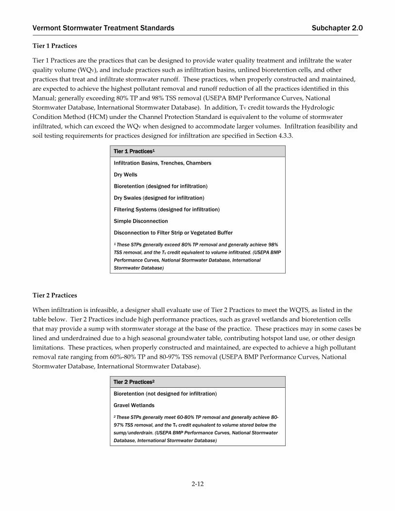
Tier 1 Practices
Tier 1 Practices are the practices that can be designed to provide water quality treatment and infiltrate the water
quality volume (WQV), and include practices such as infiltration basins, unlined bioretention cells, and other
practices that treat and infiltrate stormwater runoff. These practices, when properly constructed and maintained,
are expected to achieve the highest pollutant removal and runoff reduction of all the practices identified in this
Manual; generally exceeding 80% TP and 98% TSS removal (USEPA BMP Performance Curves, National
Stormwater Database, International Stormwater Database). In addition, TV credit towards the Hydrologic
Condition Method (HCM) under the Channel Protection Standard is equivalent to the volume of stormwater
infiltrated, which can exceed the WQV when designed to accommodate larger volumes. Infiltration feasibility and
soil testing requirements for practices designed for infiltration are specified in Section 4.3.3.
Tier 1 Practices1
Infiltration Basins, Trenches, Chambers
Dry Wells
Bioretention (designed for infiltration)
Dry Swales (designed for infiltration)
Filtering Systems (designed for infiltration)
Simple Disconnection
Disconnection to Filter Strip or Vegetated Buffer
1 These STPs generally exceed 80% TP removal and generally achieve 98%
TSS removal, and the TV credit equivalent to volume infiltrated. (USEPA BMP
Performance Curves, National Stormwater Database, International
Stormwater Database)
Tier 2 Practices
When infiltration is infeasible, a designer shall evaluate use of Tier 2 Practices to meet the WQTS, as listed in the
table below. Tier 2 Practices include high performance practices, such as gravel wetlands and bioretention cells
that may provide a sump with stormwater storage at the base of the practice. These practices may in some cases be
lined and underdrained due to a high seasonal groundwater table, contributing hotspot land use, or other design
limitations. These practices, when properly constructed and maintained, are expected to achieve a high pollutant
removal rate ranging from 60%-80% TP and 80-97% TSS removal (USEPA BMP Performance Curves, National
Stormwater Database, International Stormwater Database).
Tier 2 Practices2
Bioretention (not designed for infiltration)
Gravel Wetlands
2 These STPs generally meet 60-80% TP removal and generally achieve 80-
97% TSS removal, and the TV credit equivalent to volume stored below the
sump/underdrain. (USEPA BMP Performance Curves, National Stormwater
Database, International Stormwater Database)

Vermont Stormwater Treatment Standards Subchapter 2.0
2-13
Tier 3 Practices
If a site or project design cannot accommodate the Tier 1 or Tier 2 Practices specified above because of site or
design constraints, but excluding costs, then a designer may use Tier 3 Practices to meet the WQTS, as listed in the
table below. Tier 3 Practices include lined dry swales, lined filters, wet ponds, and shallow surface wetlands.
These practices, when properly constructed and maintained, are expected to achieve a pollutant removal rate
ranging from 50-60% TP and approximately 80% TSS removal (USEPA BMP Performance Curves, National
Stormwater Database, International Stormwater Database).
Tier 3 Practices3
Dry Swales (not designed for infiltration)
Filtering Systems (not designed for infiltration)
Wet Ponds
Shallow Surface Wetlands
3 These STPs generally meet 50-60% TP removal and achieve 80% TSS removal, and the TV credit is equivalent to volume stored below the sump/underdrain, if applicable. (USEPA BMP Performance Curves, National Stormwater Database, International Stormwater Database)
This detailed 2017 VSMM – Water Quality Practice Selection, Design Guidance assists with the selection of STPs for
meeting the Water Quality Treatment Standard, to ensure that the highest performing acceptable STPs are used
when feasible, including those identified as Tier 1 Practices, which include infiltration and disconnection practices,
and second, Tier 2 Practices, which include filtration practices. A designer should review this design guidance and
shall complete the permit application materials, which include completing the STP Selection Matrix and following
the step-by-step instructions for Water Quality Practice Selection, and, for projects proposing the use of Tier 3
Practices, providing written justification.
Under the permit application materials, designers shall:
• Evaluate the feasibility to locate STPs on the tract or tracts of land on which the project is located, and if the
project is part of a common plan of development, designers shall evaluate the feasibility to locate STPs on
contiguous land that is part of the common plan of development when such land is owned or controlled by
the applicant.
• On projects with multiple stormwater drainage areas, provide a site-specific feasibility justification for each
drainage area for which the use of a Tier 3 Practice is proposed to meet the Water Quality Treatment
Standard.
• Evaluate all required elements for STP design when determining STP feasibility, however in the event that
an exact numerical criterion specified within the various required design elements cannot be complied
with precisely, due to site constraints, the designer may use his or her best professional judgment to specify
minor variations from numerical design criteria pursuant to the requirements of Section 4.0 of the 2017
VSMM in order to select the higher tier practice.
In consideration of the fact that site constraints and project specifics may vary widely, this information serves as
additional guidance to designers evaluating STP feasibility:

Vermont Stormwater Treatment Standards Subchapter 2.0
2-14
First and foremost, under the permit application materials, cost is not a feasibility consideration. It is important
that project developers and stormwater designers consider stormwater treatment during initial project design in
order to identify the anticipated surface area required for stormwater management and the locations that may be
available for siting the highest tier practices.
There are however, circumstances that influence the siting of a project, its configuration, or its size, that may further
limit the ability to utilize the highest tier practice for water quality treatment. The following guidance identifies
several considerations for feasibility. In permit application materials, designer’s will be required to sufficiently
document limitations, and project placement and design, in consideration of feasibility. The following is not
considered to be an all-inclusive list of all potential feasibility constraints.
Natural Resource Protection and Restoration
Federal, state, and local laws and permits for the protection and restoration of wetlands, lake shorelands,
floodplains, river corridors, drinking water sources, threatened and endangered species and their critical habitat,
and other natural resources may require excluding many areas of a property from consideration for siting of not
only STPs, but from development activities altogether. Designers may consider non-structural practices in these
situations to the extent allowed by law.
Existing or Proposed Electrical or Sewer/Water Infrastructure
The presence of existing electrical or sewer/water infrastructure may exclude certain areas of a property from being
utilized for STPs, when co-locating an STP with the existing use would be incompatible. Additionally, land
reserved for electrical or sewer/water infrastructure via easement or other legal requirement may exclude certain
areas of a property from being utilized for STPs, when co-locating an STP with the future use would be
incompatible with the future use. In addition, some areas that are near this type of infrastructure may be off limits,
if a required setback is applicable. Designers should carefully consider the layout of utilities and site areas
available for the highest performing practices prior to finalizing other utility design. In the case of overhead
electrical infrastructure, designers should still consider the ability to site STPs below such infrastructure when
placement will not be incompatible with utility line operation and maintenance.
Existing Stormwater Infrastructure
The presence of existing STPs may exclude areas from being utilized for new STPs. In these instances, it is expected
that designers look first for the ability to design an in-line or off-line higher tier practice in concert with existing
infrastructure, even when such design requires modification of existing conveyances such as catch basins and pipes
or open channels, or when a design requires some modification to the existing STP.
Existing Topography or Site Grading
Existing topography and site grading limitations may prevent the routing of collected stormwater runoff to areas
most conducive to the siting of Tier 1 or Tier 2 Practices.
Existing Zoning Bylaws
Existing zoning bylaws that pertain to property line setbacks, natural resource setbacks, and minimum
roadway/driveway widths, may exclude areas from being utilized for STPs. Designers are encouraged to configure
sites during initial project layout to minimize impervious area footprint and maximize areas conducive to the siting
of higher performing STPs.
Stormwater Hotspots
Stormwater hotspots (Section 2.3) generate higher concentrations of hydrocarbons, trace metals, and toxicants than
are found in typical stormwater runoff. Petroleum distribution centers, hazardous material loading and storage
facilities, and other industrial sites, including contaminated sites, may include drainage areas that are considered
stormwater hotspots. Although stormwater runoff contributing from hotspots may preclude the use of infiltration
practices, other practices when lined, may serve as viable options for the use of higher performing practices. Areas

Vermont Stormwater Treatment Standards Subchapter 2.0
2-15
on a property with contamination also may not be suitable for certain STPs, particularly those that infiltrate (See
Section 2.3). Designers are strongly encouraged to check in with the Agency’s Waste Management and Prevent
Division (WMPD) to determine whether contamination may limit where STPs are sited or which STPs may be used.
Presence of Existing Buildings
The presence and footprint of an existing building will preclude the use of that area for stormwater treatment, and
there is no requirement to remove or modify existing buildings to accommodate stormwater treatment for a project.
However, the redevelopment and expansion of impervious surfaces at already developed sites may provide new
treatment opportunities, including below existing impervious surfaces, such as parking lots, which could also
involve voluntarily retrofitting existing impervious surfaces to meet applicable treatment requirements. The
presence of existing buildings may also require consideration for basement flooding and contributing stormwater
runoff from those existing impervious surfaces.
Interference with Material Conditions of Existing Land Use Permits
An existing land use permit may include conditions that would preclude the use of areas for stormwater treatment.
Documentation of this permit condition would be required to preclude an area from STP siting.
Safety Considerations
A valid safety issue may preclude the use of areas for stormwater treatment.
Limitation/Extent of Existing Right-of-Way or Easement
An existing right-of-way (ROW) or easement may preclude areas from being considered for siting of STPs, when
such ROW or easement boundary or width precludes the ability to construct STPs or route stormwater.

Vermont Stormwater Treatment Standards Subchapter 2.0
2-16
Is the designer attempting to use a STP already existing on the
site to meet the Water Quality Treatment Standard (WQTS)?
Evaluate the site for use of Tier 1
Practices for meeting the WQTS.
Can the site accommodate a Tier
1 Practice to meet the WQTS?
NO
YES
Use a Tier 1 Practice
to meet the WQTS,
other applicable
standards can be met
with any practice in
the 2017 VSMM.
NO
YES
Is the existing STP a Tier 1 Practice that currently
meets the 2002 or 2017 VSMM design requirements
and is sized to meet the WQTS?
Use the existing Tier 1
Practice to meet the WQTS,
and modify to the extent
practicable to meet 2017
VSMM design requirements.
YES NO
Can the site accommodate an
in-line or off-line Tier 1
Practice in conjunction with
the existing STP for meeting
the WQTS?
Use an in-line or off-
line Tier 1 Practice to
meet the WQTS.
YES
Can the site accommodate an in-
line or off-line Tier 2 Practice in
conjunction with the existing
STP for meeting the WQTS?
NO YES
NO
Use an in-line or
off-line Tier 2
Practice to meet the
WQTS.
Is the existing STP identified as an
acceptable practice for meeting the WQTS
in the 2017 VSMM, and does the practice,
at minimum, meet the 2002 VSMM
design requirements?
Use the existing Tier 3 Practice,
modify to the extent practicable
to the 2017 VSMM design
requirements, and size to meet
the WQTS.
YES
NO
Design must forego consideration of
existing STP for meeting the WQTS, and
utilize STP in the 2017 VSMM that
meets the WQTS, per the requirements
of Section 2.2.4.1.
Can the site
accommodate a
Tier 2 Practice to
meet the WQTS?
Use a Tier 2 Practice to
meet the WQTS, other
applicable standards can
be met with any practice
in the 2017 VSMM.
YES
NO
Use a Tier 3 Practice. Complete
site specific justification for use
of a Tier 3 Practice.
Is the existing STP a Tier 2 Practice
that currently meets the 2002 or
2017 VSMM design requirements
and is sized to meet the WQTS?
NO
Use the existing Tier 2
Practice to meet the WQTS,
and modify to the extent
practicable to meet 2017
VSMM design requirements.
YES

Vermont Stormwater Treatment Standards Subchapter 2.0
2-17
2.2.4.2. Water Quality Peak Flow Calculation
The peak rate of discharge for the water quality design storm (1 inch, 24-hour storm event, Type II rainfall
distribution) is required for the sizing of rate based treatment practices and off-line diversion structures.
Conventional United State Department of Agriculture (USDA) Natural Resource Conservation Service (NRCS)
methods for calculating runoff have been found to underestimate the volume and rate of runoff for rainfall events
less than 2 inches.
To adapt NRCS methods for the water quality storm, a modified Curve Number (CN) shall be calculated using the
WQV and the following equation:
CN =
1000
[10 + 5P + 10Qa − 10(Qa2 + 1.25QaP) 1/2]
Equation 2-3
where:
P = rainfall, in inches (use the water quality design storm, 1”)
Qa = runoff volume, in inches (equal to WQV ÷ area)
The calculated CN shall be used to estimate the peak discharge rate of the water quality storm using a computer
aided hydrologic model (TR-20 or an approved equivalent). Time of concentration shall be computed pursuant to
Section 2.2.4.3.
Design Guidance:
▪ When the WQV has been otherwise reduced for the redevelopment of impervious surfaces based on other
design strategies in this Manual, or has been reduced based on reductions in existing impervious surface area,
these reductions should not be considered in the WQV used in the above equation for calculation of the peak
rate of discharge for the water quality design storm.
2.2.4.3. Time of Concentration
To calculate peak rates for compliance with the requirements of this Manual, the time of concentration (TC) shall be
determined for use with each modeled subcatchment. Time of concentration shall be determined using the
Watershed Lag Method (Lag/CN Method) as described by NRCS and shown below:
𝑇𝑐 = (𝑙)0.8 [(
1000𝐶𝑁′
− 10) + 1]0.7
1140𝑌0.5
Equation 2-4
where:
Tc = time of concentration (hours)
𝑙 = hydraulic length (ft)
CN’ = retardance factor
Y = average catchment slope (%)
The hydraulic length (𝑙) is defined as the longest flow path in the catchment and can be calculated using the
empirical relation presented by NRCS:

Vermont Stormwater Treatment Standards Subchapter 2.0
2-18
𝑙 = 209𝐴0.6 Equation 2-5
where:
A = subcatchment area (ac)
Or by determining the longest flow path length by direct measurement from a plan sheet.
Retardance factor (CN’) is used to describe the land cover of the catchment of interest, and shall be approximated
by the adjusted or flow weighted composite curve number used to describe the catchment.
Average catchment slope (Y) may be determined a number of ways, including in AutoCAD, ArcGIS, any of the
methods included in Section 630.1502 (a) of the NRCS National Engineering Handbook, or by the following
relation:
𝑌 = 100
𝐶𝐼
𝐴 Equation 2-6
where:
C = contour length (feet)
I = contour interval (feet)
A = subcatchment area (square feet) (Design Guidance)
Contour length (C) means the total length of all contour lines within the catchment, including all closed contours,
as directly measured from a plan sheet.
The Watershed Lag Method incorporates average catchment slope and the composite land cover characteristics of a
catchment, and is therefore preferred to spatially explicit methods, such as the NRCS Velocity Method (TR-55
Method), which represent time of concentration for a catchment with varying slopes and land cover characteristics
using the characteristics of a single flow path.
The Watershed Lag Method shall be used for determination of peak rates for existing and proposed condition
modeling, proposed condition modeling with treatment volume credit and an associated adjusted curve number,
and water quality storm modeling.
Other time of concentration calculation methods may be considered on a case-by-case basis, but shall require pre-
application discussion and subsequent Agency approval. Any spatially explicit time of concentration methods
proposed under this framework (TR-55/Velocity Method) shall include no more than 100 feet of sheet flow in the
total flow path length.
Design Guidance:
▪ A CN’ value of no less than 50 and no greater than 95 should be used for calculation of Time of Concentration
(Tc) in Equation 2-4.
▪ In order to obtain the adjusted or flow weighted composite curve number, to be represented as CN’, for use in
the above Tc calculation (Equation 2-4) a designer will be required to utilize Agency provided application and
design materials, including worksheets for auto-calculation; or

Vermont Stormwater Treatment Standards Subchapter 2.0
2-19
o Calculate the catchment runoff depth (Q), for the applicable development scenario (i.e. pre-
development and/or post-development) for each of the land cover types within the catchment and
for each applicable storm event;
o Sum all of the calculated runoff depths (Q) for the individual catchment land uses for each storm
event and determine weighted Q for the catchment; and
o Use the weighted Q value to calculate the adjusted or flow-weighted CN, represented as CN’, using
Equation 2-12, for you in the Time of Concentration calculation (Equation 2-4).
Channel Protection Standard
The pollutant load transported by stormwater runoff from the developed landscape is not the only deleterious
impact that stormwater has on receiving streams. Management of stormwater is also necessary to protect stream
channels from scour and erosion.
To comply with the Channel Protection Standard, the 1-year, 24-hour storm shall be managed to protect stream
channels from the changes in timing, runoff volume, and peak flow rate of stormwater runoff that occurs as the
result of development activities.
In Vermont, the 1-year, 24-hour rainfall ranges between 1.8 and 3.0 inches (NOAA, Atlas 14, 2015). For purposes of
compliance with the Channel Protection Standard, rainfall values from NOAA Atlas 14, or its replacement, and a
Type II rainfall distribution shall be used unless specific data are available for a particular site location and prior
approval has been obtained from the Agency.
The Channel Protection Standard shall be satisfied using the Hydrologic Condition Method, the Extended
Detention Method, the Alterative Extended Detention Method, or by some combination of these methods. The
Hydrologic Condition Method (HCM) and the Extended Detention Method are described in the following
subsections, followed by the Alternative Extended Detention Method. For projects that will use distributed and
non-structural treatment for the majority of a site, a designer may elect to use the Alternative Extended Detention
Method to satisfy the Channel Protection Standard as identified in Section 2.2.5.4.
The Channel Protection Standard shall be waived for:
A site where the pre-routed, post-development discharge for the 1-year, 24-hour storm is less than 2 cubic feet
per second. “Pre-routed post-development discharge” means the runoff after development, including post-
development conveyance, but without STPs. When examining whether or not the site qualifies for this waiver,
off-site runoff does not need to be considered, however the overall common plan of development shall be
considered.
A site with a direct discharge to waters with a drainage area equal to or greater than 10 square miles and that is
less than 5% of the watershed area at the site’s upstream boundary.
For a project that has more than one discharge point and that discharges to different receiving waters, waiver
eligibility shall be determined on a “per receiving water” basis. Receiving waters are considered separate if the
drainage area at their downstream point of confluence is greater than 10 square miles.
2.2.5.1. Hydrologic Condition Method
The Hydrologic Condition Method (HCM) is used to determine a suite of practices, including the mandatory post-
construction Soil Depth and Quality Standard, which, when implemented, will approximate runoff characteristics
of “woods in good condition” for the 1-year, 24-hour storm event.

Vermont Stormwater Treatment Standards Subchapter 2.0
2-20
The HCM is based on the curve number (CN) hydrology method developed by the USDA NRCS. The hydrologic
condition volume (HCV) is the difference between the pre-development and post-development site runoff for the 1-
year, 24-hour storm.
To comply with the HCM in acre-feet, the following equation shall be used to determine the HCV:
𝐻𝐶𝑉 =
(𝑄1𝑃𝑜𝑠𝑡 − 𝑄1𝑃𝑟𝑒) ∗ 𝐴
12 Equation 2-7
where:
HCV = hydrologic conditions treatment volume (acre-feet)
Q1Post = post-development runoff depth for the 1-year, 24-hour storm (inches)
Q1Pre = pre-development runoff depth for the 1-year, 24-hour storm (inches)
A = post-development contributing drainage area (acres)
Runoff depth (Q) shall be calculated by the NRCS runoff methods or approved equivalent pre- and post-
development condition.
Q =(P−0.2∗S)2
P+0.8∗S for P≥0.2*S
Q = 0 for P<0.2*S
Equation 2-8
where:
Q = runoff depth in inches
P = precipitation in inches
𝑆 = 1000/𝐶𝑁 − 10
The standard for characterizing the pre-development land use shall be “woods in good condition.” CN values for
“woods in good condition” are presented on Table 2-5. Existing development not subject to jurisdiction may be
modeled as the existing condition.
Table 2-5. Runoff Curve Numbers for Woods in Good Condition
Cover Type HSG A HSG B HSG C HSG D
Woods in Good Condition 30 55 70 77
When a site area is composed of multiple land cover types, the runoff volume from each curve number shall be
calculated separately and summed. Area-weighted curve numbers shall not be used, unless the Agency provides
prior approval.
Compliance with the HCM shall be achieved when the total TV provided on the site is equal to or greater than the
HCV.
A list of practices acceptable for meeting the Channel Protection Standard by the HCM is presented in Table 2-6; all
practices are described in detail in Subchapter 4.0 of this Manual.
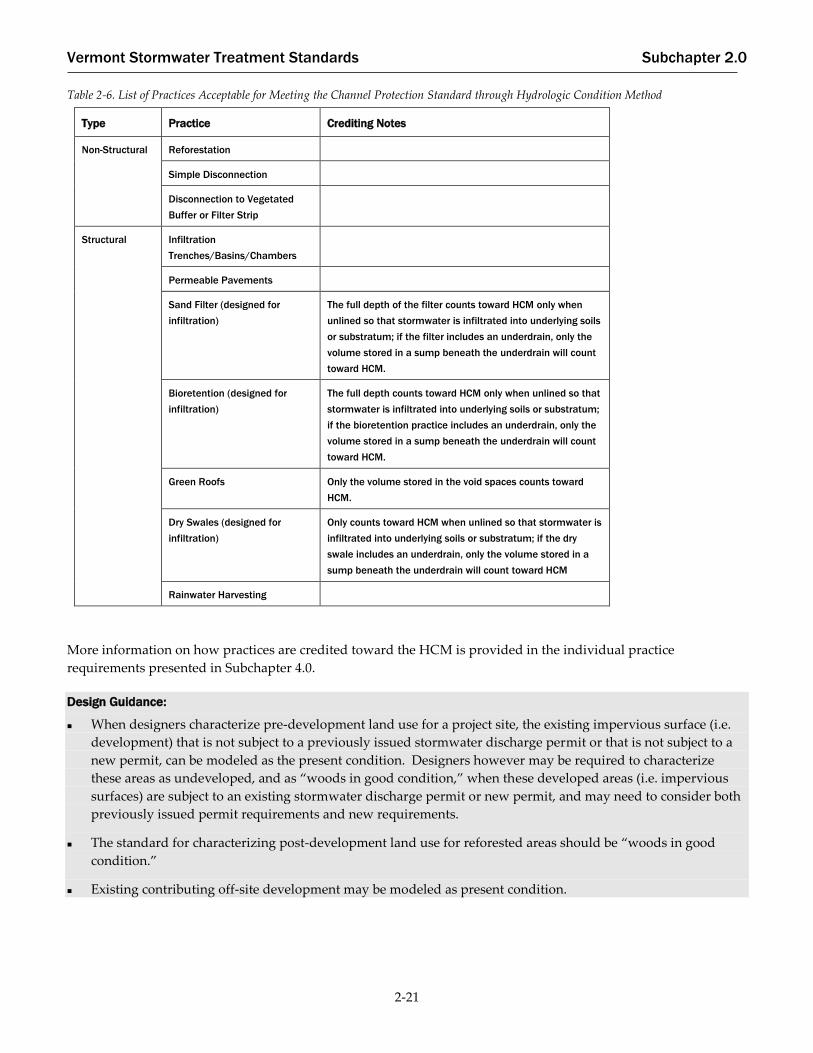
Vermont Stormwater Treatment Standards Subchapter 2.0
2-21
Table 2-6. List of Practices Acceptable for Meeting the Channel Protection Standard through Hydrologic Condition Method
Type Practice Crediting Notes
Non-Structural Reforestation
Simple Disconnection
Disconnection to Vegetated
Buffer or Filter Strip
Structural Infiltration
Trenches/Basins/Chambers
Permeable Pavements
Sand Filter (designed for
infiltration)
The full depth of the filter counts toward HCM only when
unlined so that stormwater is infiltrated into underlying soils
or substratum; if the filter includes an underdrain, only the
volume stored in a sump beneath the underdrain will count
toward HCM.
Bioretention (designed for
infiltration)
The full depth counts toward HCM only when unlined so that
stormwater is infiltrated into underlying soils or substratum;
if the bioretention practice includes an underdrain, only the
volume stored in a sump beneath the underdrain will count
toward HCM.
Green Roofs Only the volume stored in the void spaces counts toward
HCM.
Dry Swales (designed for
infiltration)
Only counts toward HCM when unlined so that stormwater is
infiltrated into underlying soils or substratum; if the dry
swale includes an underdrain, only the volume stored in a
sump beneath the underdrain will count toward HCM
Rainwater Harvesting
More information on how practices are credited toward the HCM is provided in the individual practice
requirements presented in Subchapter 4.0.
Design Guidance:
When designers characterize pre-development land use for a project site, the existing impervious surface (i.e.
development) that is not subject to a previously issued stormwater discharge permit or that is not subject to a
new permit, can be modeled as the present condition. Designers however may be required to characterize
these areas as undeveloped, and as “woods in good condition,” when these developed areas (i.e. impervious
surfaces) are subject to an existing stormwater discharge permit or new permit, and may need to consider both
previously issued permit requirements and new requirements.
The standard for characterizing post-development land use for reforested areas should be “woods in good
condition.”
Existing contributing off-site development may be modeled as present condition.

Vermont Stormwater Treatment Standards Subchapter 2.0
2-22
2.2.5.2. Extended Detention Method
For those sites where the practice or suite of practices under the HCM are insufficient to achieve compliance with
the Channel Protection Standard, additional STPs may need to be implemented to protect stream channels from
degradation.
To comply with the Extended Detention Method, storage of the channel protection volume (CPV) shall be provided
by means of extended detention (ED) storage for the 1-year, 24-hour rainfall event. Extended detention time shall
only be required down to the 1-inch minimum orifice size. As noted previously, the Channel Protection Standard
rainfall depths will vary depending on project location.
If a stormwater discharge is to a cold water fish habitat, 12 hours of extended detention shall be provided, and if a
stormwater discharge is to a warm water fish habitat, 24 hours of extended detention shall be provided. Cold
water fish habitats and warm water fish habitat designations are listed in the Vermont Water Quality Standards,
Appendix A.
In evaluating a site for channel protection through the Extended Detention Method, the following criteria shall be
applied:
Extended detention shall be demonstrated by center of mass detention time and released at a roughly uniform
rate over the required release period.
The model TR-20, or approved equivalent, shall be used for determining peak discharge rates, and for routing
detention ponds.
Time of concentration (Tc) shall be computed pursuant to Section 2.2.4.3 of this Manual.
Pursuant to Section 2.2.5.3, adjusted curve numbers shall be used when runoff volumes have been reduced
through runoff reduction STPs.
Extended detention shall be provided for the on-site and off-site runoff that drains to the detention structure.
If off-site runoff is rerouted, the designer shall ensure that such rerouting will not cause channel erosion or
flooding problems in the area where the water is discharged.
Off-site areas shall be modeled as “existing condition” for the 1-year storm event.
Orifices less than 3 inches shall be protected from clogging. The minimum allowable orifice size is 1 inch.
Design Guidance:
When designers characterize pre-development land use for a project site, the existing impervious surface (i.e.
development) that is not subject to a previously issued stormwater discharge permit or that is not subject to a
new permit, can be modeled as the present condition. Designers however may be required to characterize
these areas as undeveloped, and as “woods in good condition,” when these developed areas (i.e. impervious
surfaces) are subject to an existing stormwater discharge permit or new permit, and may need to consider both
previously issued permit requirements and new requirements.
The standard for characterizing post-development land use for reforested areas should be “woods in good
condition.”
Existing contributing off-site development may be modeled as present condition.

Vermont Stormwater Treatment Standards Subchapter 2.0
2-23
2.2.5.3. Calculating Adjusted Curve Numbers
When the Channel Protection Standard is partially met through the HCM, an adjusted CN shall be calculated for
the project site. The adjusted CN (CNadj) shall then be used to demonstrate compliance with the Channel Protection
Standard by extended detention and flood protection (QP10 and QP100), where required, using the following
procedure:
The cumulative treated volume is equal to the sum of the TV for the individual runoff reduction practices provided
on the site:
𝐻𝐶𝑉𝑎𝑐𝑡 = ∑ 𝑇𝑉 Equation 2-9
where:
HCVact = the cumulative TV provided on the site, in acre-feet
TV = the runoff reduction volume credit provided by a single treatment practice, in acre-
feet
The cumulative treated volume shall be converted into a runoff depth in watershed inches (QAct):
𝑄𝐴𝑐𝑡 = (
𝐻𝐶𝑉𝑎𝑐𝑡 ∗ 12
𝐴) Equation 2-10
where:
QAct = the volume of runoff reduced in watershed inches
A = the site area, in acres
The remaining untreated watershed inches (QRem) shall then be calculated as:
𝑄𝑅𝑒𝑚 = 𝑄𝑃𝑜𝑠𝑡 − 𝑄𝐴𝑐𝑡 Equation 2-11
where:
QPost = the post-development runoff for the design storm before treatment
An adjusted CN for the impervious area shall then be calculated as follows:
𝐶𝑁𝑎𝑑𝑗 = (
200
(𝑃 + 2 ∗ (𝑄𝑅𝑒𝑚) + 2) − √(5 ∗ 𝑃 ∗ 𝑄𝑅𝑒𝑚 + 4 ∗ (𝑄𝑅𝑒𝑚)2)) Equation 2-12
where:
P = precipitation depth of the design storm.
For the Channel Protection Standard, the precipitation event is the 1-year, 24-hour storm and QPost is the 1-year post
development runoff before treatment. For QP10 and QP100, P and QPost for the 10-year and 100-year, 24-hour storm
events shall be used to calculate a separate CNadj for each applicable storm.
Once CNadj is computed, CNadj shall be used for areas treated by STPs that reduce runoff in demonstrating
compliance with CPV, QP10, and QP100, as discussed in more detail in the following subsections.

Vermont Stormwater Treatment Standards Subchapter 2.0
2-24
2.2.5.4. Alternative Extended Detention Method
For projects that will use distributed structural STPs or other non-structural STPs for the majority of a site, a
designer may elect to use the Alternative Extended Detention Method to satisfy the Channel Protection Standard.
To comply with the Alternative Extended Detention Method, the designer shall demonstrate that the 1-year 24-
hour storm post-developed peak discharge from the site, after providing distributed and non-structural treatment,
is no greater than the peak discharge from the site when modeled as if 12-hour detention were provided.
For the purpose of this alternative demonstration of compliance, the designer shall route all post-development
stormwater runoff from the site to a hypothetical dry detention basin. Proposed water quality treatment practices
throughout the site shall not be included in the hypothetical model. The dry detention basin shall be sized to
provide 12 hours of extended detention on a center of mass basis using the following design constraints:
All outflow shall be routed through a single vertical bottom orifice, sized to provide 12 hours of center of mass
detention time.
Peak storage depth within the hypothetical pond for the 1-year 24-hour storm event shall submerge the outlet
orifice, but shall not exceed a depth of 8’.
Pond side slopes shall be 3:1 or flatter.
The peak outflow rate from this hypothetical pond shall be compared to the site-wide post-treatment 1-year, 24-
hour storm peak outflow rate.
If the post-development site with all proposed treatment produces a peak 1-year flow rate that is less than the
hypothetical pond peak outflow rate, the site shall meet the Channel Protection Standard.
Overbank Flood Protection Standard (QP10)
To comply with the Overbank Flood Protection Standard, the post-development peak discharge rate shall not
exceed the pre-development peak discharge rate for the 10-year, 24-hour storm event.
The Agency may require a downstream analysis as described in Section 2.5 when there are known drainage
problems or known flooding conditions, or as otherwise deemed appropriate.
In evaluating overbank flood protection and related STPs, the following criteria shall be applied:
An adjusted curve number (CNadj), consistent with the analysis performed in Section 2.2.5.3, shall be applied to
post-development conditions to determine the required volume of overbank flood control storage.
For expansions of previously non-permitted projects, the site shall mean the expanded portion of the site,
including all areas within the limits of construction.
The model TR-20, or approved equivalent, shall be used for determining peak discharge rates, and for routing
detention ponds.
Time of concentration (Tc) shall be computed pursuant to Section 2.2.4.3 of this Manual.
The standard for characterizing pervious pre-development land use for on-site areas shall be “woods in good
condition.” Existing development not subject to jurisdiction may be modeled as the existing condition.
Off-site areas shall at a minimum be modeled as "existing condition."
Safe passage of the 100-year, 24-hour storm event shall be provided for off-site areas that drain to the STP.

Vermont Stormwater Treatment Standards Subchapter 2.0
2-25
Site designers shall use rainfall values from NOAA Atlas 14, or its replacement, and a Type II rainfall
distribution unless specific data are available for a particular site location and prior approval has been obtained
from the Agency.
Compliance with the Overbank Flood Protection Standard shall not be required if:
A site has a direct discharge to waters with a drainage area greater than or equal to 10 square miles;
A downstream analysis is completed, pursuant to Section 2.5, that indicates overbank flood control is not
necessary for the site; or
The pre-routed, post-development discharge for the 10-year, 24-hour storm is less than 2 cubic feet per second.
“Pre-routed post-development discharge” means the runoff after development, including post-development
conveyance, but without STPs. When examining whether or not the site qualifies for this waiver, off-site runoff
does not need to be considered, however the overall common plan of development shall be considered.
Design Guidance:
When designers characterize pre-development land use for a project site, the existing impervious surface (i.e.
development) that is not subject to a previously issued stormwater discharge permit or that is not subject to a
new permit, can be modeled as the present condition. Designers however may be required to characterize
these areas as undeveloped, and as “woods in good condition,” when these developed areas (i.e. impervious
surfaces) are subject to an existing stormwater discharge permit or new permit, and may need to consider both
previously issued permit requirements and new requirements.
The standard for characterizing post-development land use for reforested areas should be “woods in good
condition.”
Existing contributing off-site development may be modeled as present condition.
Extreme Flood Protection Standard (QP100)
To comply with the Extreme Flood Protection Standard, the post-development peak discharge rate shall not exceed
the pre-development peak discharge rate for the 100-year, 24-hour storm event.
The purpose of this treatment standard is to prevent flood damage from infrequent but very large storm events,
maintain the boundaries of the pre-development 100-year floodplain, and protect the physical integrity of a STP.
The Agency may require a downstream analysis as described in Section 2.5 when there are known drainage
problems or known flooding conditions, or as otherwise deemed appropriate.
In evaluating extreme flood control and related STPs, the following criteria shall be applied:
An adjusted curve number (CNadj), consistent with the analysis performed in Section 2.2.5.3, shall be applied to
post-development conditions to determine the required volume of extreme flood control storage.
For expansions of previously non-permitted projects, the site shall mean the expanded portion of the site,
including all areas within the limits of construction.
The model TR-20, or approved equivalent, shall be used for determining peak discharge rates, and for routing
detention ponds.
Time of concentration (Tc) shall be computed pursuant to Section 2.2.4.3 of this Manual.
The standard for characterizing pre-development land use for on-site areas shall be “woods in good condition.”
Existing development not subject to jurisdiction may be modeled as the existing condition.

Vermont Stormwater Treatment Standards Subchapter 2.0
2-26
Off-site areas shall at a minimum be modeled as "existing condition."
Safe passage of the 100-year 24-hour storm event shall be provided for off-site areas that drain to the STP.
Site designers shall use rainfall values from NOAA Atlas 14, or its replacement, and a Type II rainfall
distribution unless specific data are available for a particular site location and prior approval has been obtained
from the Agency.
Compliance with the Extreme Flood Protection Standard shall not be required if:
A site has a direct discharge to waters with a drainage area equal to or greater than 10 square miles and that is
less than 5% of the watershed area at the site’s upstream boundary;
The impervious area on site or otherwise associated within a common plan of development, constructed after
2002, is less than 10 acres; or
A downstream analysis is completed, pursuant to Section 2.5, that indicates extreme flood control is not
necessary for the site.
Design Guidance:
When designers characterize pre-development land use for a project site, the existing impervious surface (i.e.
development) that is not subject to a previously issued stormwater discharge permit or that is not subject to a
new permit, can be modeled as the present condition. Designers however may be required to characterize
these areas as undeveloped, and as “woods in good condition,” when these developed areas (i.e. impervious
surfaces) are subject to an existing stormwater discharge permit or new permit, and may need to consider both
previously issued permit requirements and new requirements.
The standard for characterizing post-development land use for reforested areas should be “woods in good
condition.”
Existing contributing off-site development may be modeled as present condition.
Stormwater Hotspots Stormwater hotspots generate higher concentrations of hydrocarbons, trace metals, and toxicants than are found in
typical stormwater runoff. Petroleum distribution centers, hazardous material loading and storage facilities, and
other industrial sites may include drainage areas that are stormwater hotspots. Hotspots may also include sites
where subsurface contamination is present from prior land use, due to the increased threat of pollutant migration
associated with increased hydraulic loading from infiltration systems. Designers are encouraged to contact the
Agency’s Waste Management and Prevention Division in advance of proposing infiltration at a contaminated site
prior to application submittal.
To prevent pollution of groundwater resources, stormwater runoff that comes in contact with a hotspot shall not be
treated with structural or non-structural STPs that rely upon infiltration, including infiltration basins, infiltration
trenches, infiltration storage chambers, dry wells, unlined bioretention practices, unlined dry swales, unlined
filters, and disconnection.
To treat stormwater that comes in contact with a hotspot, other STPs identified in this Manual may be used if they
are lined (e.g., lined bioretention areas).
Prior to incorporating stormwater infiltration STPs into a project, designers shall review a site’s current or
proposed use, and consult with the Agency as to whether the site or site drainage area is a hotspot.

Vermont Stormwater Treatment Standards Subchapter 2.0
2-27
Redevelopment This Section establishes treatment standards for projects or portions of projects where areas of existing impervious
surface will be redeveloped. Because redevelopment may present a wide range of constraints and limitations, this
Manual provides redevelopment projects with additional flexibility in implementing STPs to meet the applicable
standards.
For redevelopment, except for redevelopment of public transportation projects subject to Subchapter 6.0, the WQTS
is:
The existing impervious surface area shall be reduced by 25% and restored to meet the Post-Construction Soil
Depth and Quality Standard, Section 3.0, where applicable;
A STP or STPs shall be designed to capture and treat 50% of the WQV from the redeveloped impervious surface
area; or
A combination of water quality volume treatment (WQV) and impervious surface reduction equal to 50% of the
WQV where one percent of impervious reduction is equivalent to two percent of WQV, using the following
equation.
𝑊𝑄𝑉𝑅 = (50 − 2×𝐼𝑅𝑒𝑑𝑢𝑐𝑒𝑑)×𝑊𝑄𝑉 Equation 2-13
where:
WQVR = Water quality volume for redeveloped site (Design Guidance: acre-feet)
IReduced = Existing impervious reduced (%)
Redevelopment projects may consider use of other design strategies, including Site Balancing and Net Reduction
pursuant to Section 2.1.1 of this Manual.
If none of the foregoing options are technically feasible, a designer may propose alternatives that would achieve an
equivalent pollutant reduction. In such cases, the designer shall document, pursuant to the Section 3.0
documentation requirements, the site constraints or limitations and expected pollutant removal for any proposed
alternative STP. Proposed alternatives shall be subject to Agency approval. If the Agency determines that a
proposed alternative will not provide equivalent pollutant reduction or presents greater risks to water quality, in
consideration of impervious surface proximity to water resources, existing site conditions, or other factors, the
Agency shall deny the proposed alternative.

Vermont Stormwater Treatment Standards Subchapter 2.0
2-28
Downstream Analysis for QP10 and QP100 Depending on the shape and land use of a watershed, it is possible that the upstream peak discharge may arrive at
the same time a downstream structure is releasing its peak discharge, thus increasing the cumulative peak
discharge. As a result of this “coincident peaks” problem, it is often necessary to evaluate conditions downstream
from a site to ensure that effective out-of-bank control is provided.
Figure 2-2: Graphical Depiction of Coincident Peak Phenomena (ARC, 2001), Design Guidance
A downstream analysis shall be required when deemed necessary by the Agency (e.g., known drainage problems;
known flooding conditions), as required by the Overbank Flood Protection Standard (Section 2.2.6), or as required
by the Extreme Flood Protection Standard (Section 2.2.7).
The criteria used for the downstream analysis is referred to as the “10% rule.” Under the 10% rule, a hydrologic
and hydraulic analysis is extended downstream to the point where the site represents 10% of the total drainage
area. For example, a 60-acre site would be analyzed to the point downstream where the total drainage area reaches
600 acres.
In cases where the site area is already less than 10% of the drainage area at the point of discharge, the downstream
analysis allowable increase shall be scaled according to
Table 2-7 below, which reduces allowable increases as the percentage of the site area relative to contributing
drainage area decreases. In addition, in these cases, the analysis may need to be extended downstream to the first
structure (e.g. bridge, culvert) if the structure is reasonably expected to be affected by the project.

Vermont Stormwater Treatment Standards Subchapter 2.0
2-29
Table 2-7. Allowable Increases for Downstream Analysis
Site Area Relative to Drainage Area of Receiving Water at
Discharge Point
Allowable Flow Rate and Velocity Increase at Analysis
Point
10% 5% allowable increase
5 to <10% 2.5% allowable increase
2.5% to <5% 1.25% allowable increase
1.25% to <2.5% 0.63% allowable increase
<1.25% 0.31% allowable increase
At a minimum, the analysis shall include the hydrologic and hydraulic effects of all culverts and obstructions
within the downstream channel, and assess whether an increase in water surface elevations will adversely impact
existing buildings or structures or adversely impact existing land uses. The analysis shall compute flow rates and
velocities (for the overbank and extreme flood control storms) downstream to the location of the 10% rule for
present conditions and proposed conditions (i.e., before and after development of the applicable site).
If flow rates and velocities (for QP10 and QP100) without detention increase by less than 5% from the present
condition, or as otherwise required by Table 2-7 above, and no existing structures are adversely impacted, then no
additional analysis is necessary and no detention is required. If the flow rates and velocities increase by more than
5%, or as otherwise required by Table 2-7 above, the designer shall either redesign the project with a detention
structure and complete the analysis with detention, propose corrective actions to the impacted downstream areas,
or utilize some combination of the above. The Agency may require the designer to complete additional
investigations on a case-by-case basis depending on the magnitude of the project, the sensitivity of the receiving
water resources, or other issues such as past drainage or flooding complaints.
Special caution shall be used when the analysis shows that no detention structure is required. Designers shall
demonstrate that runoff will not cause downstream flooding within the stream reach to the location of the 10%
rule. The absence of on-site detention shall not be perceived to waive or eliminate other treatment standards
requirements.
A downstream analysis shall include, at a minimum, a hydrologic investigation of the site area draining to a
proposed detention practice and of the contributing watershed to the location of the 10% rule for the 10- and
possibly 100-year storms, and a hydraulic analysis of the stream channel below the practice to the location of the
10% rule (e.g., a HECRAS water surface profile analysis or approved equivalent). Depending on the magnitude of
the impact and the specific conditions of the analysis, additional information and data may be necessary.
Additional information may include collecting field run topography, establishing building elevations and culvert
sizes, investigating specific drainage concerns or complaints, and identifying all culverts, control, conveyance, and
stormwater treatment and control contributing to the point of analysis.
Downstream Analysis Steps.
1. Calculation of pre- and post-development stormwater runoff at the point of the 10% rule.
a. Locate the downstream analysis study point downstream of the project discharge point where site area is
10% of the total contributing drainage area (i.e. where the drainage area is 10 times the project site area).
NOTE: In cases where the site area is already less than 10% of the drainage area at the point of discharge,
the downstream analysis allowable increase shall be scaled according to Table 2-7 above, which reduces
allowable increases as the percentage of the site area relative to contributing drainage area decreases. In

Vermont Stormwater Treatment Standards Subchapter 2.0
2-30
addition, in these cases, the downstream analysis may need to be extended downstream to the first
structure (e.g. bridge, culvert) if the structure is reasonably expected to be affected by the project.
b. Model the existing condition runoff from the entire contributing off-site drainage area to the identified
analysis point. As a separate component to the model, model the project site for both existing conditions
and post-development. The project site model should then be linked to the remainder of the contributing
drainage area model to calculate the existing and post-development flow rates and velocities to the
identified analysis point.
2. Comparison of existing condition and post-development stormwater runoff at the point of the 10% rule.
a. If flows and velocities increase by less than 5% at the analysis point, or as otherwise required by above,
then no detention practice may be required if and only if the following is confirmed via hydraulic analyses:
i) Verify the stream channel and all structures downstream to the identified analysis point, and all
conveyances to the discharge point (off-site and project site) have adequate capacity to safely convey
the increased runoff, such that no structures, buildings, or existing land uses are adversely impacted.
A simple channel model may be used in limited cases to demonstrate that the post-development peak
volume will not exceed channel capacity. In most scenarios, a more in-depth hydraulic water surface
profile analysis may be required to satisfy the analysis (e.g. HECRAS). If peak flow conditions are
predicted to access the floodplain during peak flow conditions, then pre- and post- inundation
mapping may be required to demonstrate that proposed conditions will not create or exacerbate
adverse impacts to structures, buildings, or existing land uses. More rigorous and detailed hydraulic
analyses may be required for evaluation of the 100-year 24-hour design storm.
b. If flows and velocities increase by 5% or greater at the analysis point, or as otherwise required by Table 2-7
above, then the designer shall provide enough stormwater detention on the project site so that flows and
velocities do not increase by 5% or greater at the analysis point, or as otherwise required by Table 2-7, shall
comply with Step 2(a)(i) above.

Vermont Stormwater Treatment Standards Subchapter 3.0
3-1
3.0 POST-CONSTRUCTION SOIL DEPTH AND
QUALITY
Introduction. Naturally occurring, undisturbed soil and vegetation provide important stormwater functions
including: water infiltration; nutrient and pollutant adsorption; sediment and pollutant biofiltration; water
interflow storage and transmission; and pollutant decomposition. These functions are largely lost when
development removes native soil and vegetation and replaces it with minimal topsoil and sod. Not only are these
important stormwater functions diminished, but such landscapes may themselves become pollution generating
pervious surfaces due to increased use of pesticides, fertilizers, and other landscaping and household/industrial
chemicals; the concentration of pet wastes; and pollutants that accompany roadside litter.
Ensuring soil depth and quality provides greater stormwater functions in the post-development landscape,
provides increased treatment of pollutants and sediments that result from development, and minimizes the need
for some landscaping chemicals, thus reducing pollution through prevention.
To comply with the Post-Construction Soil Depth and Quality Standard, a project shall meet the requirements of
this Subchapter 3.0.
Figure 3-1. Post-Construction Soil Depth and Quality Standard Field Verification, Design Guidance
Post-Construction Soil Depth and Quality Feasibility
Required Elements:
The Post-Construction Soil Depth and Quality Standard shall apply to all disturbed areas within the limits of
the site which are not covered by an impervious surface, incorporated into a structural stormwater treatment
practice, or engineered as structural fill once development is complete.
Undisturbed areas where the duff layer and native topsoil are retained meet the intent of this Standard and
shall not be subject to disturbance solely for the purpose of soil amendment.
This practice shall not be required on soil slopes greater than 33 percent.

Vermont Stormwater Treatment Standards Subchapter 3.0
3-2
The practice may be adjusted to reflect the mapped topsoil depth for soils that do not naturally have 4 inches or
more of topsoil as indicated on the NRCS Official Soil Series Descriptions for the mapped soil types. In these
cases, a copy of the Official Soil Series Description shall be included with the application. However, the
practice standard of 4 inches shall apply on sites with fill soils that have replaced native soils, and sites where
native topsoil was removed, regardless of whether or not existing soils have less than 4 inches of topsoil.
Areas subject to significant regular foot or vehicle traffic may be waived from compliance with this Standard,
but designers shall model the area in question as “open space in poor condition” rather than as “open space in
good condition.” These areas shall be clearly identified on the plan sheet. Requests for such waivers shall be
reviewed on a case-by-case basis and subject to Agency approval.
The identification of areas exempt from the standard because of structural fill shall be at the designer’s
discretion based on their best professional judgement, but will require certification that such areas are not able
to meet this Standard. Areas exempt from the Standard because of structural fill shall not be used as
disconnection areas under Simple Disconnection or Disconnection to Filter Strips and Vegetated Buffers.
Design Guidance:
Establishing a minimum soil quality and depth will provide improved on-site management of stormwater flow
and water quality where soils are disturbed for. Meeting the minimum Post-Construction Soil Depth and
Quality Standard is, however, not the same as the preservation of naturally occurring soil and vegetation.
Soil organic matter can be improved or increased through numerous materials such as compost, composted
woody material, Exceptional Quality biosolids (EQ biosolids) and forest product residuals. It is important that
the materials used to meet the Post-Construction Soil Depth and Quality Standard be appropriate and
beneficial to the plant cover to be established. Likewise, it is important that imported topsoils improve soil
conditions and do not have an excessive percent of clay fines.
Post-Construction Soil Depth and Quality Treatment
Required Elements:
Soil retention. Retain, in an undisturbed state, the duff layer and native topsoil to the maximum extent
practicable.
Soil quality. All areas subject to the Standard shall demonstrate the following:
A topsoil layer with a minimum organic matter content of 4% dry weight in planting beds and turf areas. The
topsoil layer shall have a minimum depth of 4 inches, except where tree roots limit the depth of incorporation
of amendments needed to meet the criteria or where native mapped soils indicate less than 4 inches of
naturally occurring topsoil on an NRCS Official Soil Series Description. In those cases in which native mapped
soils indicate less than 4 inches of naturally occurring topsoil, restored top soil depth shall match that indicated
on the NRCS Official Soil Series Description.
Compost and other materials shall be used that meet the following requirements:
o The compost or other materials shall have a carbon to nitrogen ratio below 25:1.
o Compost shall meet the definition of “compost” in the Agency’s Solid Waste Management Rules or
shall meet the contaminant standards in the Vermont Solid Waste Management Rules §6-1104(g)(6-
7), §6-1105(e)(8-9), and §6-1106(e)(7-9). Compost or other organic materials may be amended to
meet the foregoing requirements.
Vermont Stormwater Treatment Standards Subchapter 3.0
3-3
o Exceptional Quality biosolids (EQ biosolids) may be used as a soil amendment, at a maximum
proportion of 35% of the total soil volume, and shall be well mixed with existing soil before or
during application.
The resulting soil shall be conducive to the type of vegetation to be established.
The soil quality requirements shall be met by using one or a combination of the following methods:
o Option 1: Leave undisturbed native vegetation and soil, and protect from compaction during
construction. Identify areas of the site that will not be stripped, logged, graded, or driven on, and
fence off those areas to prevent impacts during construction. Failure to establish and maintain
exclusionary controls around these areas during the construction phase may trigger the
requirement to restore soils per one of the following options.
o Option 2: Amend existing site topsoil or subsoil in place.
▪ Scarify or till subsoils to 4 inches of depth or to depth needed to achieve a total depth of 8
inches of uncompacted soil after calculated amount of amendment is added. Except for
within the drip line of existing trees, the entire surface shall be disturbed by scarification;
▪ Amend soil to meet organic content requirements:
• PRE-APPROVED RATE: Place 1 inch of composted material with an organic
matter content between 40 and 65% and rototill into 3 inches of soil, or
• CALCULATED RATE: Place calculated amount of composted material or
approved organic material and rototill into depth of soil needed to achieve 4
inches of settled soil at 4% organic content;
▪ Rake beds to smooth and remove surface rocks larger than 2 inches in diameter; and
▪ Water or roll to compact soil in turf areas to 85% of maximum dry density.
o Option 3: Remove and stockpile existing topsoil during grading.
▪ Stockpile soil on site in a designated controlled area, at least 50 feet from surface waters,
wetlands, floodplains, or other critical resource areas;
▪ Scarify or till subgrade to a depth of 4 inches. Except for within the drip line of existing
trees, the entire surface shall be disturbed by scarification;
▪ Stockpiled topsoil shall also be amended, if needed, to meet the organic content
requirements:
• PRE-APPROVED RATE: Compost shall be incorporated with an organic matter
content between 40 and 65% into the topsoil at a ratio 1:3, or
• CALCULATED RATE: Incorporate composted material or approved organic
material at a calculated rate to achieve 4 inches of settled soil at 4% organic
content;
▪ Replace stockpiled topsoil prior to planting; and
▪ Rake to level, and remove surface rocks larger than 2 inches in diameter.
o Option 4: Import topsoil mix, or other materials for mixing, including compost, of sufficient
organic content and depth.

Vermont Stormwater Treatment Standards Subchapter 3.0
3-4
▪ Scarify or till subgrade to a depth of 4 inches. Except for within the drip line of existing
trees, the entire surface shall be disturbed by scarification;
▪ Place 4 inches of imported topsoil mix on surface. The imported topsoil mix shall contain
4% organic matter. Soils used in the mix shall be sand or sandy loam as defined by the
USDA;
▪ Rake beds to smooth and remove surface rocks larger than 2 inches in diameter; and
▪ Water or roll to compact soil in turf areas to 85% of maximum dry density.
Post-Construction Soil Depth and Quality Vegetation and Landscaping
Required Elements:
A site-specific plan for soil management must be provided that:
o Identifies areas on the site subject to the Standard;
o Includes construction details and notes on the various methods the contractor may use to meet the
Standard. Soil depth and quality shall be established towards the end of construction and once
established, protected from compaction, such as from large machinery, vehicle traffic, and from
erosion; and
o Includes instructions for contractor verification of the Standard, including a sampling scheme, for
verification by the contractor, that includes nine 8-inch deep test holes per acre of area subject to
Standard. Test holes shall be excavated using only a shovel driven solely by inspector’s weight
and shall be at least 50 feet apart from each other.
A dense and vigorous vegetative cover shall be established over turf areas.

Vermont Stormwater Treatment Standards Subchapter 4.0
4-1
4.0 ACCEPTABLE STORMWATER TREATMENT
PRACTICES
Introduction. This Subchapter presents detailed design requirements for the suite of STPs that may be utilized to
meet one or more of the treatment standards identified in Section 2.0. The STPs identified in the following sections
specify the ability for the practice to meet the applicable treatment standards.
Section 4.1 identifies a range of pre-treatment practices that both improve water quality and enhance the
effective design life of the STPs. Designers are encouraged to consider which pre-treatment practice is best
suited to the STPs selected for the site. Pre-treatment is required for all STPs that will provide water quality
treatment for non-rooftop stormwater runoff.
Section 4.2 presents a suite of non-structural STPs that are intended to shift stormwater design away from
centralized management and focus instead on infiltrating and treating stormwater runoff close to the source.
STPs discussed include: disconnections and reforestation. Designers are encouraged to exhaust opportunities
to incorporate non-structural STPs into site design before considering structural STPs.
Section 4.3 presents structural STPs that are intended to augment treatment provided by non-structural STPs
to fully achieve the standards identified in Section 2.0. STPs discussed include: green roofs, permeable
pavement, rainwater harvesting, bioretention, dry swales, infiltration trenches/basins, filtering systems,
treatment wetlands, and wet ponds.
Section 4.4 presents an overview of alternative STPs, where a designer may consider the use of a STP that is
proprietary or a STP that is otherwise not specifically included in this Manual for meeting applicable treatment
standards. Alternative STPs are subject to Agency review and approval.
Minor Variations from Numerical Design Criteria. In the event that an exact numerical criterion specified within
the various required design elements cannot be complied with precisely due to site constraints, the designer may
use his or her best professional judgment to specify minor variations from numerical design criteria. These
variations shall be certified by the designer as being equivalent in performance to the required design element, and
any such variation must be specifically identified in the Notice of Intent (NOI) letter to the Agency. The Agency
shall then have the option to either approve the variation on a case-specific basis, or require the system to be
treated as an Alternative STP, as described in Section 4.4, subject to an individual permit. Designers are strongly
encouraged to seek Agency approval for any minor variation prior to submittal of a stormwater permit application.

Vermont Stormwater Treatment Standards Subchapter 4.0
4-2
Pre-Treatment Practices Pre-treatment shall be provided for stormwater runoff, except for roof runoff that does not commingle with other
stormwater runoff prior to treatment. Pre-treatment practices are designed to improve water quality and enhance
the effective design life of STPs by consolidating the maintenance to a specific location. However, they do not meet
pollutant removal goals or stormwater volume reduction standards on their own.
WQV pre-treatment practices shall be combined with acceptable volume reduction and control, water quality, or
storage practices to meet applicable standards. Pre-treatment practices include:
Pre-Treatment Swales (Grass Channels)
Vegetated Filter Strips
Sediment Forebays
Deep Sump Catch Basins
Proprietary Devices
In cases where the practice is a proprietary device, specifications and design criteria can typically be obtained from
vendors. As the Agency approves specific proprietary devices for pre-treatment, the Agency will maintain and
update a list of these approved practices accessible to designers.

Vermont Stormwater Treatment Standards Subchapter 4.0
4-3
Pre-Treatment Swale
Pre-treatment swales, also known as grass channels, are shallow, vegetated, earthen channels designed to convey
flows, while capturing a limited amount of sediment and associated pollutants. They are similar to conventional
drainage ditches, with the major differences being flatter side and longitudinal slopes as well as a slower design
velocity for small storm events. A pre-treatment swale differs from a treatment dry swale in that it is not intended
to provide sufficient contact time for pollutant removal processes other than those associated with larger sediment
particles and therefore can only be used for pre-treatment.
Figure 4-1. Pre-Treatment Swale, Design Guidance

Vermont Stormwater Treatment Standards Subchapter 4.0
4-4
4.1.1.1. Pre-Treatment Swale Feasibility
Required Elements:
Pre-treatment swales constructed without check dams shall have a maximum longitudinal slope of 5%. Pre-
treatment swales constructed on steeper slopes, >5% to a maximum longitudinal slope of 6%, shall include
check dams, step pools, or other grade controls.
Design Guidance
Pre-treatment swales can be applied in most development situations with few restrictions, and may be well-
suited for pre-treatment of some highway or residential road runoff due to their linear nature.
4.1.1.2. Pre-Treatment Swale Design
Required Elements:
Pre-treatment swales shall be sized as follows:
o Sizing of the pre-treatment swale width and length shall be based on the peak flow rate from the
water quality storm (see Section 2.2.4.2) and shall be designed to ensure a minimum residence time
of 5 minutes at peak velocity for flow from the inlet to the outlet of the swale. For linear projects
with no defined primary inflow location or similar projects with lateral contributing flow,
adherence to the minimum 5-minute residence time shall be based on the peak flow rate from the
water quality design storm as modeled for the contributing drainage area, and is sufficient for
meeting pre-treatment swale design requirements.
o Sufficient length for 5-minute minimum residence time for the peak discharge of the water quality
storm (1.0 inch, 24-hour event), with velocity no greater than 1 foot per second peak runoff depth
no greater than 4 inches.
The peak velocity for the 1-year storm within the pre-treatment swale must be non-erosive, in other words 3.5-
5.0 feet per second.
The bottom width of the swale shall be between 2 and 8 feet wide. The minimum width ensures a minimum
filtering surface for water quality treatment, and the maximum width prevents braiding, the formation of small
channels within the channel bottom.
Pre-treatment swales shall have a trapezoidal or parabolic cross section with side slopes less than or equal to
2H:1V.
Check Dams. Check dams or weirs shall be used to increase hydraulic residence time in the swale in steeper
applications, >5%. Plunge pools or other energy dissipation may also be considered where the elevation
difference between the tops of weirs to the downstream channel invert is a concern. The design requirements
for check dams are as follows:
o Check dams shall be composed of wood, concrete, stone, or other non-erodible material. The check
dam shall be designed to facilitate easy maintenance and periodic mowing.
o Check dams shall be firmly anchored into the side-slopes to prevent outflanking and anchored into
the channel bottom a minimum of 6 inches.
o Check dams shall be designed with a center weir sized to pass the channel design storm peak flow
(minimum 10-year 24-hour storm event if an on-line practice).

Vermont Stormwater Treatment Standards Subchapter 4.0
4-5
o Pre-treatment swales shall have the capacity to convey larger storms (minimum 10-year 24-hour
storm event) safely with 6” of freeboard.
o Armoring shall be provided at the downstream toe of the check dam, if necessary to prevent
erosion.
o Check dams shall be spaced based on channel slope, as needed to increase residence time, provide
storage volume, or meet volume attenuation requirements. The ponded water level at a downhill
check dam shall not extend above the elevation of the toe of the upstream check dam.
o Check dams composed of wood, concrete, or similar construction, shall have a weep hole or similar
drainage feature so the check dam can dewater after a storm event.
Design Guidance
During construction, it is important to stabilize the swale promptly by establishing vegetation. Applying a
seed mix with both perennial and seasonal grasses, and mulch will ensure prompt stabilization. Natural or
synthetic erosion control matting may also aid in stabilization of the pre-treatment swale.
Pre-treatment swales should not be designed to intercept groundwater. Swales may seasonally intercept
seasonally high groundwater during periods of excessive precipitation and spring snow melt.
Pre-Treatment Filter Strip
Filter strips (i.e., vegetated filter strips, grass filter strips, and grassed filters) are vegetated areas that are intended
to treat distributed flow from adjacent impervious areas. Filter strips function by slowing runoff velocities and
filtering out sediment and other pollutants, and providing some limited infiltration into underlying soils. With
proper design and maintenance, filter strips can provide effective pre-treatment. Proper grading to ensure
distributed flow throughout the length of the practice is necessary for a properly functioning filter strip.
Figure 4-2. Pre-Treatment Filter Strip, Design Guidance
4.1.2.1. Filter Strip Feasibility
Required Elements:
Filter strips designed for pre-treatment shall have a maximum average slope of 6%.

Vermont Stormwater Treatment Standards Subchapter 4.0
4-6
The soils underlying the filter strip shall, at minimum, meet the criteria included in the Post-Construction Soil
Depth and Quality Standard (Subchapter 3.0).
Design Guidance
Filter strips are best suited for pre-treatment of stormwater runoff from driveway, roads and highways, roof
downspouts, and small parking lots.
4.1.2.2. Filter Strip Design
Required Elements:
The filter strip shall abut the entire length of the contributing area to ensure that runoff from all portions of the
site are pre-treated.
To limit the occurrence of concentration flow conditions, the maximum impervious contributing flow path
length to a filter strip shall be limited to 75 feet for impervious surfaces and 150 feet for pervious surfaces and
the filter strip shall be graded in such a way as to prevent the concentration of flow.
A roughly uniform stone diaphragm at the top of the slope is required for filter strips providing pre-treatment
for contributing impervious surfaces with slopes greater than 5%.
o The roughly uniform stone diaphragm shall be created by excavating a 2-foot wide and 1-foot deep
trench that runs on the same contour at the top of the filter strip.
o Flow shall travel over the impervious area and to the practice, including the stone diaphragm as
distributed flow.
o A layer of filter fabric shall be placed between the stone and the underlying soil in the trench.
o If the contributing drainage area is steep (6% slope or greater), then larger stone shall be used in
the diaphragm.
Design Guidance
Filter strips should be designed on slopes between 2% and 4%. Steeper slopes encourage concentrated flow;
slopes flatter than 2% may result in ponding.
Designers should choose a grass that can withstand relatively high velocity flows, and both wet and dry
periods.
Sediment Forebay
A sediment forebay may be a separate cell within the STP formed by a barrier such as an earthen berm or concrete
weir, or may be designed with conveyance linking to STP. Forebays may be used as a pre-treatment practice to
minimize maintenance needs for nearly any STP. The purpose of a forebay is to provide pre-treatment by settling
out sediment particles at the inflow to a STP. This can enhance treatment performance, reduce maintenance, and
increase the longevity of a STP.

Vermont Stormwater Treatment Standards Subchapter 4.0
4-7
Figure 4-3. Sediment Forebay, Design Guidance
4.1.3.1. Sediment Forebay Design
Required Elements:
The forebay shall be sized to contain a minimum of 10% of the WQV (greater than 10% may be required
depending on the downstream STP) and be of an adequate depth to prevent re-suspension of collected
sediments during the design storm, often 4 to 6 feet deep, but in no case less than 2 feet deep.
The forebay shall have side slopes no steeper than 2:1.
The forebay shall have a minimum length to width ratio of 1:1 and a preferred minimum length to width ratio
of 2:1 or greater. When riprap is used, designers shall appropriately size riprap to effectively dissipate erosive
velocities.
The forebay shall consist of a separate cell, formed by an acceptable barrier such as an earthen berm, or a
concrete weir. If a channel is used to convey flows from the forebay to the primary STP, the bed and side
slopes of the channel shall be armored.
The outer perimeter of all deep permanent pool areas (4 feet or greater) shall be surrounded by a safety bench
that generally extends 15 feet outward (a 10-foot minimum bench is allowable on sites with extreme space
limitations at the discretion of the Agency) from the normal water edge to the toe of the side slope. The
maximum slope of the safety bench shall be 6%. This requirement shall be waived where forebay side slopes
are 4:1 or flatter.
The outlet from the forebay shall be designed in a manner to prevent erosion of the embankment and primary
pool.
The outlet invert shall be elevated in a manner such that a minimum of 10% of the WQV can be stored below it.
This outlet may be configured in a number of ways, such as a culvert, weir, or spillway channel. The outlet
shall be designed to convey the same design flow proposed to enter the structure.
A fixed vertical sediment depth marker shall be installed in the forebay to measure sediment deposition.
Direct access for appropriate maintenance equipment shall be provided to the forebay, and may include a ramp
to the bottom of the embankment if equipment cannot reach all points within the forebay from the top of the
embankment.

Vermont Stormwater Treatment Standards Subchapter 4.0
4-8
Design Guidance
The bottom of the forebay may be hardened (i.e., concrete, asphalt, riprap) to make sediment removal easier
and minimize the possibility of excavating subsurface soils or undercutting embankments during routine
maintenance.
Sediment testing may be required prior to sediment disposal when stormwater runoff contributes from a
hotspot land use or activity.
Deep Sump Catch Basins
Deep sump catch basins are modified inlet structures that can be installed in a piped stormwater conveyance
system to remove coarse sediment, trash, and debris. They can also serve as temporary spill containment devices
for floatables such as oils and greases.
4.1.4.1. Deep Sump Catch Basin Feasibility
Required Elements:
Deep sump catch basins used as pre-treatment devices shall be located “off-line”, with connections to
downstream structures taking place at manholes or buried pipe connections, but shall not contain inlet pipes
from other structures. Catch basin-to-catch basin or inlet-to-inlet configurations are acceptable for conveyance,
but they shall not be counted as a pre-treatment practice.
The contributing drainage area to each deep sump catch basin shall not exceed 0.25 acres of impervious cover.
Design Guidance
Potential site constraints include the presence of utilities, bedrock, and high groundwater elevations.
Figure 4-4. Deep Sump Catch Basin, Design Guidance

Vermont Stormwater Treatment Standards Subchapter 4.0
4-9
Hoods may be susceptible to displacement or damage from cleaning activities. This should be considered in the
configuration of the tops of structures (e.g., use of eccentric cones or flat tops with the inlet offset from
alignment with the hood) to minimize risk of damage from cleaning equipment. However, the configuration
should also permit access for repositioning or replacing the hood.
4.1.4.2 Deep Sump Catch Basin Design
Required Elements:
The deep sump shall be a minimum of 4 feet deep below the lowest pipe invert, or four times the diameter of
the outlet pipe, whichever value is greater.
The inlet grate shall be sized based on the contributing drainage area, to ensure that the flow rate does not
exceed the capacity of the grate.
Inlet grates designed with curb cuts shall reach the back of the curb cut to prevent flow bypass.
Hooded outlets shall be used.
So that the sump can be easily inspected and maintained, the inlet grate shall not be welded to the frame.
Sufficient maintenance access shall be provided when designing the geometry of deep sump catch basins.
Design Guidance
The inlet grate should have openings not more than 4 square inches, to prevent large debris from collecting in
the sump.
Proprietary Pre-Treatment Devices
Proprietary devices are manufactured systems that use proprietary settling, filtration, absorption/adsorption,
vortex principles, vegetation, and other processes to provide stormwater treatment. Three general types of
proprietary devices are most often considered for stormwater applications: oil and grit separators, hydrodynamic
devices, and filtering systems. Some types of proprietary devices may not be able demonstrate the level of water
quality performance required by this Manual and as such, are only allowable for pre-treatment provided an
independent third-party monitoring program, such as one of the programs identified in Section 4.4.1, verifies that
the proposed device removes a minimum of 50% TSS for the WQV including during the maximum flow during the
water quality event (Qwq).
4.1.5.1. Proprietary Device Feasibility
Required Elements:
Proprietary devices shall be designed and installed in compliance with the manufacturer’s recommendations.
Proprietary devices shall be designed as off-line systems, or shall have an internal bypass to avoid large flows
and re-suspension of pollutants, to be used as pre-treatment for other practices.
4.1.5.2. Proprietary Devices Design
Required Elements:
To qualify as an acceptable pre-treatment device, proprietary devices shall remove a minimum of 50% TSS, as
verified by an independent third-party monitoring group. For flow based proprietary practices, TSS removal
shall be demonstrated for the Qwq routed to the practice.
Vermont Stormwater Treatment Standards Subchapter 4.0
4-10
Flow-through proprietary devices shall be designed to pass the entire WQV and the Qwq. Qwq shall be calculated
in accordance with Section 2.2.4.2.
A proprietary storage device shall be sized based on the required pre-treatment volume, which is expressed as
a percentage of the WQV.
Flows higher than the design flow or that exceed the pre-treatment storage volume shall be configured to
bypass the system, either by designing the practice as an off-line system or providing an internal bypass.
For proprietary devices, such as oil and grit separators, all baffles shall be tightly sealed at sidewalls and at the
roof to prevent the escape of oil.
Proprietary devices shall be maintained in accordance with manufacturers’ guidelines, and at a minimum
when sediment has reached 50% of the designed storage capacity.
Proprietary devices shall be located such that they are accessible for maintenance and emergency removal of oil
and chemical spills.

Vermont Stormwater Treatment Standards Subchapter 4.0
4-11
Non-Structural Practices
Reforestation and Tree Planting
Trees act as natural reservoirs by intercepting and storing rainfall, which can reduce stormwater runoff volume and
mitigate its effects. Tree canopies intercept rainfall before it becomes stormwater runoff, and the uncompacted soil
into which trees are ideally planted can be used to capture and treat runoff. Trees may also be incorporated into
bioretention and filter STP designs found in Section 4.3.
For the purposes of this Manual, credit for reforestation is given for three methods:
Active reforestation involves planting a stand or block of trees at a project site, or individual trees with the
explicit goal of establishing a mature forest canopy or distributed cover that will intercept rainfall, increase
evapotranspiration rates, and enhance soil infiltration rates.
Passive reforestation consists of protecting a portion of a project site from mowing and allowing native
vegetation to reestablish.
Single tree credit for the planting of individual trees.
The credits outlined in this Section may be applied to site areas regardless of location on site. For reforested areas
that receive runoff from impervious surfaces, credit may be sought under the requirements for Simple
Disconnection (Section 4.2.2) or Disconnection to Filter Strips and Vegetated Buffers (Section 4.2.3).
Reforestation and tree planting may be considered in urban and suburban areas, as well as in rural situations
where existing unforested areas are proposed for development, to provide shade and stormwater retention and to
add aesthetic and natural habitat value.
4.2.1.1. Reforestation and Tree Planting Feasibility
Required Elements:
The minimum contiguous area of active or passive reforestation shall be a minimum of 2,500 square feet.
The minimum width for reforested areas shall be 25 feet.
To receive credit towards HCV, the reforested area shall be within the site or may be contiguous with the site,
provided that in either case, the reforested area is under the same ownership or control as the site and shall be
identified as protected from development and disturbance on the site plan.
For reforested areas that will receive runoff from impervious surfaces, slope limitations shall be consistent with
the requirements of Simple Disconnection (Section 4.2.2) or Disconnection to Filter Strips and Vegetated Buffers
(Section 4.2.3).
Tree species selection shall be appropriate to the soil and site conditions of the area to be reforested.
Designers may consider designated foot traffic access to reforested areas by use of a path or trail. Impervious
surface areas located within or across reforested areas shall not count toward reforestation credit.
Design Guidance
The use of this practice should be limited to areas where there is sufficient space for fully grown trees, space for
nearby utilities, and a separation distance from structures.
Consulting an arborist, forester, or landscape architect early in the reforestation design process is highly
recommended.
Vermont Stormwater Treatment Standards Subchapter 4.0
4-12
Reforestation areas may require temporary or permanent demarcation (e.g. split-rail fence, boulders, etc.) to
restrict or limit unnecessary access and to protect plantings following establishment.
4.2.1.2. Reforestation and Tree Planting Treatment
Required Elements:
The soil within the area to be reforested shall meet the Post-Construction Soil Depth and Quality Standard
(Subchapter 3.0).
Tree species selected shall be well-suited to the site with consideration for natural species composition and
diversity of forests in the immediate or local area.
If the reforestation area is serving as a vegetated filter strip to receive additional credit through Disconnection
to Filter Strips and Vegetated Buffers (Section 4.2.3), the required elements of that practice shall also be
satisfied, taking steps necessary to ensure that additional routed runoff does not cause erosion or degrade the
quality of ground cover.
TV credit for active reforestation shall be equal to 0.1 inches multiplied by the reforested area (i.e. a reforested
area of 1 acre equates to a TV credit of 363 cubic feet).
TV credit for passive reforestation shall be equal to 0.05 inches multiplied by the practice area.
TV credit for single tree plantings shall be 5 cubic feet per tree planted.
4.2.1.3. Reforestation and Tree Planting Vegetation and Landscaping
Required Elements:
A planting plan for the reforestation area shall be prepared to indicate how the area will be stabilized and
established with vegetation. The plan shall include at a minimum the following elements: delineation of the
reforestation area, selection of corresponding plant species, plant locations, sequence for preparing the
reforestation area (including soil amendments, if needed), and sources of plant material. Landscaping plans
shall clearly specify how vegetation within the reforested area will be established and managed. These plans
shall include trees and shrubs that are native or adapted to Vermont, and procedures for preventing noxious or
invasive plants. Managed turf (e.g., playgrounds, regularly mown and maintained open areas) is not an
acceptable form of vegetation management within reforested areas.
The entire reforestation area shall be covered with an approved native seed mix covered with mulch to help
retain moisture and provide a beneficial environment for the reforestation.
Active and passive reforestation areas shall not be maintained as landscaped areas. Forest leaf litter, duff, and
volunteer sapling and understory growth shall not be removed.
Trees planted for the single tree credit shall be at least 2-inch caliper for deciduous trees, or at least six feet tall
for conifers.
Design Guidance
The planting plan, applicable to active reforestation, should be designed to fully occupy the reforestation area
with vegetation early on, with the expectation that some trees will be removed or allowed to die to achieve
appropriate spacing. This allows the function of the site to be maximized early on, and minimizes the
establishment of undesirable plants. One strategy for meeting these goals is to pre-plan the winners and losers.
Plant out and invest the most in the trees that will own the site in 10 years, and between them, plant trees and
shrubs that are acceptable, but cheaper and likely to be weeded out in favor of the winners.

Vermont Stormwater Treatment Standards Subchapter 4.0
4-13
The recommended density of plantings for active reforestation is 300 large canopy trees per acre, which
corresponds to plantings located approximately 12 feet on center. Examples of large canopy trees include sugar
maple, white pine, and Northern red oak. When shrubs are substituted for trees, there should be 10 shrubs per
one large canopy tree. Two small canopy trees, such as crabapple, hawthorn, or eastern red bud, may also be
substituted for one large canopy tree. Two thirds of selected trees must be large canopy, and reforestation
methods should be targeted to achieve 75% forest canopy within ten years.
Selection of tree species for reforestation should consider the composition of area forests:
o The USGS LANDFIRE map may be consulted for delineation of forest type:
http://landfire.cr.usgs.gov/viewer/. The NatureServe Explorer provides descriptions for each
ecological system, including descriptions of prevalent tree species within each forest type:
http://explorer.natureserve.org/.
o Additional guidance for appropriate tree selection is available at the Vermont Urban and
Community Forestry (UCF) website: http://www.vtcommunityforestry.org/resources/tree-
selection. Important relevant resources include the Vermont Tree Selection Guide
(http://www.vtcommunityforestry.org/sites/default/files/pictures/vttree_guide.pdf) and the UCF
Tree Selection Tool (http://www.vtcommunityforestry.org/resources/tree-care/tree-selection).
The minimum size recommendation for trees is saplings 6-8 feet in height. The minimum size recommendation
for shrubs is 18-24 inches in height, or 3-gallon size.
New trees should be planted following appropriate procedures (e.g., the International Society of
Arboriculture’s Planting New Trees, http://www.treesaregood.com/treecare/resources/New_TreePlanting.pdf).
Planting details for trees and shrubs under a variety of site conditions are available from the International
Society of Arboriculture at http://www.isa-
arbor.com/education/onlineResources/cadplanningspecifications.aspx#Planting. Planting should only be
performed when weather and soil conditions are suitable for planting.
The designer should be accountable for fully planting the space to be reforested to the extent that plantings
have space to grow, but not that other species have ample space to establish. Opportunistic re-vegetation is
typically discouraged, particularly in urban settings where invasive (and likely exotic) plants will be most
likely to quickly establish. However, native opportunistic re-vegetation that occurs is allowable in reforested
areas to supplement the planting plan, provided noxious or invasive plants are promptly removed.
The final size of the trees in relation to nearby utilities should be considered when designing the planting plan.
Soils and mulch play a significant role in pollutant removal and tree health. Selection of soils and mulch
intended to improve stormwater controls should allow water to infiltrate into the soil, with planting soil
characteristics and volume tailored to meet the needs of a healthy tree.
A 4-inch layer of organic mulch may be installed around newly planted trees to aid in moisture retention. If
mulch is used, no more than 1" of mulch should be installed on top of the root ball, and mulch shall not be
installed within 6 inches of trunks or stems.
New trees should be planted following appropriate procedures (e.g., the International Society of
Arboriculture’s Planting New Trees, http://www.treesaregood.com/treecare/resources/New_TreePlanting.pdf).
Planting shall only be performed when weather and soil conditions are suitable for planting.

Vermont Stormwater Treatment Standards Subchapter 4.0
4-14
Treatment Standard Applicability:
Groundwater
Recharge
Yes. Tv credit applied to Rev.
Water Quality Yes. Tv credit applied to WQv.
Channel Protection Limited. Hydrologic Condition Method: CNAdj may provide partial credit based on Tv
credit for reforested area or tree planting.
Overbank Flood
Protection (QP10) and
Extreme Flood
Protection (QP100)
Limited. CNAdj may provide partial credit based on Tv credit for reforested area or tree
planting.
Key Elements:
Feasibility:
▪ The minimum contiguous area of active or passive reforestation shall be a minimum of 2,500
square feet.
▪ The minimum width for reforested areas shall be 25 feet.
▪ To receive Tv credit, the reforested area shall be within the site or may be contiguous with the site,
provided that in either case, the reforested area is under the same ownership or control as the site
and shall be identified as protected from development and disturbance on the site plan.
▪ Tree species selection shall be appropriate to the soil and site conditions of the area to be
reforested.
▪ Designers may consider designated foot traffic access to reforested areas by use of a path or trail.
Impervious surface areas located within or across reforested areas shall not count toward
reforestation credit.
Pre-treatment:
▪ Not applicable.
Treatment:
▪ The soil within the area to be reforested shall meet the Post-Construction Soil Depth and Quality
Standard (Subchapter 3.0).
▪ Tree species selected shall be well-suited to the site with consideration for natural species
composition and diversity of forests in the immediate or local area.
▪ TV credit for active reforestation shall be equal to 0.1 inches multiplied by the reforested area (i.e. a
reforested area of 1 acre equates to a TV credit of 363 cubic feet).
▪ TV credit for passive reforestation shall be equal to 0.05 inches multiplied by the practice area.
▪ TV credit for single tree plantings shall be 5 cubic feet per tree planted.

Vermont Stormwater Treatment Standards Subchapter 4.0
4-15
Other:
▪ A planting plan for the reforestation area shall be prepared to indicate how the area will be stabilized
and established with vegetation. The plan shall include at a minimum the following elements:
delineation of the reforestation area, selection of corresponding plant species, plant locations,
sequence for preparing the reforestation area (including soil amendments, if needed), and sources
of plant material.
▪ Active and passive reforestation areas shall not be maintained as landscaped areas. Forest leaf
litter, duff, and volunteer sapling and understory growth shall not be removed.
▪ Trees planted for the single tree credit shall be at least 2-inch caliper for deciduous trees, or at least
six feet tall for conifers.
Information contained in this table is for quick reference and is not inclusive of all requirements. All required
elements in this section shall be met in order for the STP to be in conformance with this Manual.

Vermont Stormwater Treatment Standards Subchapter 4.0
4-16
Simple Disconnection
Simple disconnection involves directing flow from residential or small commercial rooftops, sidewalks, and
residential driveways to pervious areas, where it can soak into or filter over the ground. This effectively
disconnects these surfaces from the storm drain system, reducing both runoff volume and pollutants delivered to
receiving waters. In simple disconnection practices, treatment of pollutants and total suspended solids occurs via
physical filtering and infiltration of the runoff through soil and vegetation, as well as chemical and biological
activity within the soil.
This practice is dependent on several site conditions (e.g., permeable flow path length, soils, slopes, and vegetative
cover) to function properly.
Figure 4-5. Simple Disconnection, Design Guidance
4.2.2.1. Simple Disconnection Feasibility
Required Elements:
A permeable, vegetated treatment flow path equal in length to the minimum flow path length needed for
treatment (see 4.2.2.4, below) shall be available down gradient (downslope) of the qualifying impervious
surface to effectively disconnect runoff. An exception is made for impervious surface contributing lengths less
than or equal to 10 feet, for which a disconnection length equal to the contributing length shall be specified for
slopes less than 8% or double the contributing length for slopes greater than or equal to 8%.
The width of the disconnection area shall be at least 12 feet for disconnected rooftops that discharge via
downspouts, or equal to the contributing width for all other surfaces.
The soils underlying the receiving disconnection area must, at minimum, meet the criteria included in the Post-
Construction Soil Depth and Quality standard (Subchapter 3.0).
The contributing surface impervious area to any one discharge location must not exceed 1,000 square feet. The
contributing rooftop area to an individual downspout shall not exceed 1,000 square feet.
The maximum contributing impervious flow path length to any one discharge location shall be 75 feet.
Vermont Stormwater Treatment Standards Subchapter 4.0
4-17
Parking lots shall not be directed to Simple Disconnection areas. Parking lots require pre-treatment and may
be disconnected in accordance with “Disconnection to Filter Strips and Vegetated Buffers (Section 4.2.3).
Receiving areas may be adjacent to each other, but there shall be no overlap.
The vegetated area shall have a maximum slope of 15% with land graded to promote sheet flow.
For sites with septic systems, the disconnection flow path must be cross-gradient or down-gradient of the
leachfield primary and reserve areas. This requirement may be waived if site topography clearly prohibits
flows from intersecting the leachfield.
Design Guidance
Simple disconnection may be used on any soil type, though the required disconnection length along the
disconnection flow path varies as a function of infiltration capacity.
Simple disconnection is generally not advisable for use on very small residential lots (less than 6,000 square feet
in area), although it is often possible to employ an alternate practice.
Simple disconnection areas should be located at least 25 feet from any property boundaries and consider
downslope abutters.
4.2.2.2. Simple Disconnection Conveyance
Required Elements:
Runoff must enter the disconnection area as sheet flow for the applicable design storms and shall not be
allowed to channelize.
Runoff must be conveyed as sheet flow onto and across open areas to maintain proper disconnection.
Disconnections shall be located on gradual slopes and directed away from buildings to both maintain sheet
flow and prevent water damage to basements and foundations
Where provided, downspouts must be at least 10 feet away from the nearest impervious surface to prevent
reconnection to the stormwater drainage system.
A stone diaphragm, level spreader, splash pad, or other accepted flow spreading device shall be installed at
each downspout outlet to distribute flows evenly across the flow path.
Where a gutter and downspout system is not used, runoff shall drain as either sheet flow from the contributing
surface or drain to a subsurface drain field that is not directly connected to the drainage network.
Design Guidance
A minimum separation of 5 feet should be provided between the disconnected downspout and building
foundations.
Larger storms that are not applicable should be considered in the design of the sheet flow maintaining devices.
4.2.2.3. Simple Disconnection Pre-Treatment
Required Elements:
Surfaces that qualify for simple disconnection do not require pre-treatment provided that the runoff from those
surfaces does not comingle with other runoff.

Vermont Stormwater Treatment Standards Subchapter 4.0
4-18
Design Guidance
Downspouts for conveying rooftop runoff should be equipped with leaf screens to prevent clogging.
4.2.2.4. Simple Disconnection Treatment
Required Elements:
Flow from each downspout shall be spread over a minimum 12-foot wide disconnection flow path extending
down-gradient from the structure.
A permeable, vegetated treatment area equal to the minimum flow path length needed for treatment (see Table
4-1, below) and as wide as the disconnected surface shall be available down gradient (downslope) of the
impervious cover to effectively disconnect runoff.
To qualify for shorter disconnection flow paths, the vegetated treatment area shall be located on HSG A or B
soils, or have a demonstrated infiltration rate of ≥ 0.5 inches per hour. In cases of urban or otherwise fill soils, a
site-specific soil evaluation will be necessary to qualify for shorter disconnection flow paths.
Table 4-1. Required Simple Disconnection Lengths (in direction of flow) for WQV credit
Disconnection Area Slope
HSG of soil in disconnection area Less than 8% 8-15%
A/B or infiltration rate >=0.5 in./hr 35 feet 50 feet
C/D or infiltration rate < 0.5 in./hr 65 feet 85 feet
Areas disconnected in accordance with Table 4-1 shall receive TV credit equal to 1 inch multiplied by the
disconnected area. TV for disconnections may be applied to the Recharge Standard, Channel Protection
Standard, Overbank Flood Protection Standard, and Extreme Flood Protection Standard. Full compliance with
the Channel Protection, Overbank Flood Protection, and Extreme Flood Protection Standards may require the
use of additional STPs in addition to the disconnection.
For disconnection areas on A soils, or where the infiltration rate is demonstrated to be ≥1 inch per hour by site
specific soil evaluation, TV credit shall be equal to the HCV if the disconnection length is equal to 80 feet on
slopes less than or equal to 8% or 110 feet on slopes between 8 and 15%.
Qualifying impervious surfaces with contributing lengths less than or equal to 10 feet may provide a
disconnection length equal to the contributing length on slopes less than or equal to 8% or twice the
contributing length on slopes between 8 and 15%, and as wide as the disconnected surface. TV credit shall be
equal to 1 inch multiplied by the disconnected area for where the hydrologic soil group of the disconnection
area is B, C, or D. For disconnection areas on A soils, or where the infiltration rate is demonstrated to be ≥1
inch per hour by site specific soil evaluation, TV credit shall be equal to the HCV.
Design Guidance:
Simple Disconnection is an acceptable practice that meets the Water Quality Treatment Standard and as noted
above may also be applied to the Groundwater Recharge Standard, Channel Protection Standard, Overbank
Flood Protection Standard, and Extreme Flood Protection Standard.

Vermont Stormwater Treatment Standards Subchapter 4.0
4-19
4.2.2.5. Simple Disconnection Vegetation and Landscaping
Required Elements:
A dense and vigorous vegetative cover shall be established over the receiving areas.
Design Guidance
If appropriate vegetation is not already established on site, then seed blend application is recommended. Seed
blends should be selected based on local climate. Non-clumping grass species should be selected.
Runoff may be directed to lawns or as sheet flow to undisturbed natural areas – either forest (with a well-
distributed stand of trees) or meadow (with dense grasses and/or shrubs that is mown no more than twice per
year).
Excessively fertilized lawn areas are not considered appropriate receiving areas. In order for lawns to be
considered, they should consist of low-maintenance grasses adapted to the New England region.
Treatment Standard Applicability:
Groundwater
Recharge
Yes
Water Quality Yes
Channel Protection Limited. Hydrologic Condition Method: CNAdj may provide partial credit based on Tv
credit equivalent to the WQv; Simple Disconnection on HSG A soils may receive
additional Tv credit.
Overbank Flood
Protection (QP10) and
Extreme Flood
Protection (QP100)
Limited. CNAdj may provide partial credit based on Tv credit for disconnected areas.
Key Elements:
Feasibility:
▪ The vegetated area for simple disconnection shall have a maximum slope of 15%.
▪ The width of the disconnection area shall be at least 12 feet for disconnected rooftops that
discharge via downspouts, or equal to the contributing width for all other surfaces.
▪ Parking lots shall not be directed to Simple Disconnection areas.
Pre-treatment:
▪ Surfaces that qualify for simple disconnection do not require pre-treatment provided that the runoff
from those surfaces does not comingle with other runoff.

Vermont Stormwater Treatment Standards Subchapter 4.0
4-20
Treatment:
▪ A permeable, vegetated treatment area equal to the minimum flow path length needed for treatment
(see Table 4-1, and as wide as the disconnected surface, shall be available down gradient of the
impervious cover to effectively disconnect runoff. An exception is made for impervious surface
contributing lengths less than or equal to 10 feet, for which a disconnection length shall be equal to
the contributing length for slopes less than 8%, or double the contributing length for slopes greater
than or equal to 8%.
▪ Areas disconnected in accordance with Table 4-1 shall receive TV credit equal to 1 inch multiplied by
the disconnected area. TV for disconnections may be applied to the Recharge Standard, Channel
Protection Standard, Overbank Flood Protection Standard, and Extreme Flood Protection Standard.
Full compliance with the Channel Protection, Overbank Flood Protection, and Extreme Flood
Protection Standards may require the use of additional STPs in addition to the disconnection.
▪ For disconnection areas on A soils on A soils, or where the infiltration rate is demonstrated to be ≥1
inch per hour by site specific soil evaluation, TV credit shall be equal to the HCV if the disconnection
length is equal to 80 feet on slopes less than or equal to 8% or 110 feet on slopes between 8 and
15%.
Other:
▪ A dense and vigorous vegetative cover shall be established over the receiving areas.
Information contained in this table is for quick reference and is not inclusive of all requirements. All required
elements in this section shall be met in order for the STP to be in conformance with this Manual.

Vermont Stormwater Treatment Standards Subchapter 4.0
4-21
Disconnection to Filter Strips and Vegetated Buffers
The use of disconnection can provide groundwater recharge and can reduce the volume of runoff exiting the site,
reduce pollutant and sediment loads, and reduce or slow peak flows. Filter strips and vegetated buffers are
vegetated areas that receive runoff from adjacent impervious or managed turf surfaces and allow runoff to be
slowed and filtered by plants and soil and to infiltrate into the ground. Vegetated buffers are undisturbed or
restored natural open space areas that are protected from development, and may be forested (with a well-
distributed stand of trees) or meadow (with dense grasses or shrubs that are mown no more than twice per year).
Filter strips are managed or engineered vegetated areas, usually adjacent to contributing developed areas.
The effectiveness of disconnection varies considerably based on site conditions such as the contributing drainage
area, slope and site grading, and the size and infiltration capacity of the pervious receiving area. Dense vegetative
cover, long disconnection lengths, and low surface slopes provide the most effective vegetated filters. Vegetated
filter strips and vegetated buffers are best suited to treating runoff from small segments of impervious cover such
as road shoulders and small parking lots that are adjacent to pervious surfaces.
There are two typical configurations for conveying runoff from larger rooftops or ground-level impervious surfaces
to filter strips or vegetated buffers:
When runoff uniformly enters the practice along a linear edge, such as at the edge of a road or parking lot, and
drains down-slope across the filter strip’s or vegetated buffer’s length, a stone diaphragm or similar pre-
treatment practice serves as a non-erosive transition between the impervious surface and the filter strip or
vegetated buffer.
Where the inflow to the practice is concentrated flow from a pipe or channel, an engineered level spreader
must be designed to convert the concentrated flow back to sheet flow.
Figure 4-6. Disconnection to Filter Strips and Vegetated Buffers, Design Guidance

Vermont Stormwater Treatment Standards Subchapter 4.0
4-22
4.2.3.1. Disconnection to Filter Strips and Vegetated Buffers Feasibility
Required Elements:
A permeable, vegetated treatment area equal to the minimum disconnection area length needed for treatment
must be available down gradient (downslope) of the impervious cover to effectively disconnect runoff.
The soils underlying the receiving disconnection area must, at minimum, meet the criteria included in the Post-
Construction Soil Depth and Quality standard (Subchapter 3.0).
Vegetated buffers shall remain in a natural state and must be protected to ensure that no future development,
disturbance, or clearing may occur within the area.
Vegetated filter strips shall be identified and protected to ensure that no future development, disturbance or
clearing may occur within the area, except as stipulated in the vegetation maintenance plan.
The maximum contributing impervious flow path length to any one discharge location shall be 75 feet, and the
maximum contributing pervious flow path shall be 150 feet for runoff delivered to the disconnection area as
sheet flow via a stone diaphragm. Longer contributing flow paths may be possible with proper conveyance
and engineered level spreaders.
Vegetated buffers and filter strips may be adjacent to each other, but there shall be no overlap.
Vegetated buffers shall have a maximum slope of 8%, while vegetated filter strips shall have a maximum slope
of 15%.
To qualify for shorter disconnection flow paths, the filter strip or vegetated buffer shall be located on HSG A or
B soils, or have a demonstrated infiltration rate of ≥ 0.5 inches per hour. In cases of urban or otherwise fill soils,
site specific soil evaluation will be necessary to qualify for shorter disconnection flow paths.
For sites with septic systems, the disconnection flow path must be cross-gradient or down-gradient of the
leachfield primary and reserve areas. This requirement may be waived if site topography clearly prohibits
flows from intersecting the leachfield.
Design Guidance
The overall contributing drainage area should be relatively flat to ensure sheet flow draining into the filter
strip. Where this is not possible, alternative measures, such as an engineered level spreader, can be used.
Disconnection areas should be located at least 25 feet from any property boundaries and consider downslope
abutters.
4.2.3.2. Disconnection to Filter Strips and Vegetated Buffers Conveyance
Required Elements:
A stone diaphragm or level spreader shall be provided from the disconnected area to the vegetated area to
ensure that runoff will flow in a safe and non-erosive manner during larger storm events.
Runoff shall be conveyed as sheet flow onto and across open areas to maintain proper disconnection.
Disconnections shall be located on gradual slopes and directed away from buildings to both maintain sheet
flow and prevent water damage to basements and foundations.
The maximum contributing impervious flow path length shall be 75 feet, and the maximum contributing
pervious flow path shall be 150 feet to prevent concentration of flow. Longer contributing flow paths may be
possible with proper conveyance and engineered level spreaders.

Vermont Stormwater Treatment Standards Subchapter 4.0
4-23
Stone Diaphragms. A diaphragm of stone at the top of the slope is required for both vegetated buffers and
filter strips that receive sheet flow. Stone diaphragms shall comply with the following requirements:
o The stone diaphragm shall be created by excavating a 2-foot wide and 1-foot deep trench that runs
on the same contour at the top of the filter strip.
o Flow shall travel over the impervious area and to the practice as sheet flow.
o A layer of filter fabric shall be placed between the stone and the underlying soil trench.
o If the contributing drainage area is steep (6% slope or greater), then larger stone shall be used in
the diaphragm, or an engineered level spreader shall be used in place of the stone diaphragm.
Engineered Level Spreaders. An engineered level spreader at the top of the slope is required for vegetated
buffers and filter strips that receive concentrated flow from a swale or pipe conveyance, to ensure non-erosive
sheet flow into the treatment area. The required design elements of engineered level spreaders are as follows:
o A high flow bypass shall provide safe passage for storms larger than the design storm of the level
spreader. The bypass channel shall accommodate all peak flows of the bypassed storms.
o Level spreader length shall be determined by the type of filter area and the design flow. The
design flow shall be the peak discharge of the largest storm event routed to the level spreader:
▪ For filter areas that consist of grasses or thick ground cover, 13 feet of level spreader length
per every 1 cubic foot per second (cfs) of inflow shall be provided.
▪ For filter area that are forested or reforested, 40 feet of level spreader length per every 1 cfs
of inflow shall be provided.
▪ Where the filter area is a mix of grass and forest or re-forested area, the level spreader
length shall be established by computing a weighted average of the lengths required for
each vegetation type.
▪ The minimum level spreader length shall be 13 feet and the maximum length shall be 130
feet.
▪ For determining the level spreader length, the peak discharge shall be determined using
the computational procedure outlined in Section 2.2.4.2.
o The level spreader lip shall be concrete, wood, stone, pre-fabricated metal, or other durable non-
erodible material with a well-anchored and frost-protected footer. Level spreaders shall be
designed and installed level (uniform 0% slope) and straight or convex in plan view.
o The ends of the level spreader section shall be tied back into the slope to avoid scouring around the
ends of the level spreader.
o The width of the level spreader channel on the up-stream side of the level lip shall be three times
the diameter of the inflow pipe, and the depth shall be 9 inches or one-half the inflow pipe
diameter, whichever is greater. The width of the level spreader channel shall be a minimum of 7
feet.
o The level spreader lip shall be placed 3 to 6 inches above the downstream natural grade elevation
to avoid blockage due to turf buildup. To prevent grade drops that re-concentrate the flows, a 3-
foot wide section of open-graded coarse aggregate with a 1-inch to 2.5-inch particle size
distribution, underlain by filter fabric, shall be installed just below the spreader to transition from
the level spreader to natural grade.

Vermont Stormwater Treatment Standards Subchapter 4.0
4-24
o Vegetated receiving areas down-gradient from the level spreader shall be able to withstand the
force of the flow coming over the lip of the device.
Figure 4-7. Disconnection to Filter Strip and Vegetated Buffers, via Level Spreader, Design Guidance
Figure 4-8. Disconnection to Filter Strips and Vegetated Buffers, via Level Spreader, Design Guidance

Vermont Stormwater Treatment Standards Subchapter 4.0
4-25
4.2.3.3. Disconnection to Filter Strips and Vegetated Buffers Pre-Treatment
If rooftop runoff is disconnected to a filter strip or vegetated buffer, pre-treatment is not required, provided the
runoff is routed to the receiving area in a manner such that it is unlikely to accumulate significant additional
sediment (e.g., via grass channel), and provided the runoff is not commingled with other runoff.
Required Elements:
A stone diaphragm is required as pre-treatment where runoff enters a filter strip or vegetated buffer via sheet
flow (see previous section).
If stormwater is routed to a forebay for required pre-treatment, the forebay shall be volumetrically sized for
10% of the computed WQV. Otherwise, pre-treatment designed in accordance with Section 4.1 is required.
Design Guidance
If the use of traction sand is anticipated in the contributing drainage area and runoff is delivered to the buffer
zone or filter strip as concentrated flow, the pre-treatment practice should be sized to account for the increased
sediment load resulting from traction sand application.
4.2.3.4. Disconnection to Filter Strips and Vegetated Buffers Treatment
Required Elements:
A permeable, vegetated treatment area equal to the minimum disconnection area length needed for treatment
and either as wide as the disconnected surface (for flow entering as sheet flow) or the level spreader (for
concentrated flows) shall be available down gradient (downslope) of the impervious cover to effectively
disconnect runoff.
Vegetated buffers and filter strips shall be fully vegetated.
Vegetated buffers shall remain ungraded and uncompacted to meet the Post-Construction Soil Depth and
Quality standard (Subchapter 3.0), and the over-story and under-story vegetation shall be maintained in a
natural condition.
Filter strips shall be uniformly graded to less than 15% slope, have a uniform transverse slope, meet the Post-
Construction Soil Depth and Quality standard (Subchapter 3.0), and be densely vegetated.
Table 4-2. Required Filter Strip and Vegetated Buffer Lengths (in direction of flow) by Soil Infiltration Rate and Slope Class
Maximum Disconnection Area Slope
HSG of soil in disconnection
area
Less than 8% 8-15% (filter strips
only)
A/B or infiltration rate >=0.5 in/hr 35 feet 50 feet
C/D or infiltration rate < 0.5 in/hr 65 feet 85 feet
Areas disconnected in accordance with this standard shall receive TV credit equal to 1 inch multiplied by the
disconnected area. TV for disconnections may be applied to the Recharge Standard, Channel Protection
Standard, Overbank Flood Protection Standard, and Extreme Flood Protection Standard. Full compliance with
the Channel Protection, Overbank Flood Protection, and Extreme Flood Protection Standards may require the
use of additional STPs in addition to the disconnection.

Vermont Stormwater Treatment Standards Subchapter 4.0
4-26
For disconnection areas on A soils, or where the infiltration rate is demonstrated to be ≥1 inch per hour by site
specific soil evaluation, TV credit shall be equal to the HCV if the disconnection length is equal to 80 feet on
slopes less than or equal to 8% or 110 feet on slopes between 8 and 15%.
4.2.3.5. Disconnection to Filter Strips and Vegetated Buffers Vegetation and Landscaping
Required Elements:
A minimum 90% vegetative cover shall be maintained within vegetated buffer through natural propagation or
targeted planting of native or non-invasive, naturalized species. Grading or clearing of native vegetation is
prohibited within vegetated buffers.
Vegetated filter strips shall be planted at such a density to achieve a 90% grass/herbaceous cover after the
second growing season. The filter strip vegetation may consist of turf grasses, meadow grasses, other
herbaceous plants, shrubs, and trees, as long as the primary goal of at least 90% coverage with grasses or other
herbaceous plants is achieved.
Design Guidance
For filter strips, seeding is recommended over sodding, as seeding develops a better root system and sod may
be grown on muck soils that inhibit infiltration.
At some sites, the proposed filter strip or vegetated buffer may be in turf or meadow cover, or overrun with
invasive plants and vines. In these situations, a reforestation or restoration plan for the filter strip or vegetated
buffer may be prepared.
Considerations for invasive species management should be included in landscaping and maintenance plans for
filter strips and vegetated buffers.
Treatment Standard Applicability:
Groundwater
Recharge
Yes
Water Quality Yes
Channel Protection Limited. Hydrologic Condition Method: CNAdj may provide partial credit based on Tv
credit equivalent to the WQv. Disconnection on HSG A soils may receive additional
Tv credit.
Overbank Flood
Protection (QP10) and
Extreme Flood
Protection (QP100)
Limited. CNAdj may provide partial credit based on Tv credit for disconnected areas.

Vermont Stormwater Treatment Standards Subchapter 4.0
4-27
Key Elements:
Feasibility:
▪ Vegetated buffers shall have a maximum slope of 8%, while vegetated filter strips shall have a
maximum slope of 15%.
▪ Vegetated buffers shall remain in a natural state and must be protected to ensure that no future
development, disturbance, or clearing may occur within the area.
▪ Vegetated filter strips shall be identified and protection to ensure that no future development,
disturbance or clearing may occur within the area.
Pre-treatment:
▪ A stone diaphragm is required as pre-treatment where runoff enters a filter strip or vegetated buffer
via sheet flow.
▪ A stone diaphragm or level spreader shall be provided from the disconnected area to the vegetated
area to ensure that runoff will flow in a safe and non-erosive manner during larger storm events.
▪ If stormwater is routed to a forebay for required pre-treatment, the forebay shall be volumetrically
sized for 10% of the computed WQV.
Treatment:
▪ A permeable, vegetated treatment area equal to the minimum flow path length needed for treatment
(see Table 4-2), and either as wide as the disconnected surface (for flow entering as sheet flow) or
the level spreader (for concentrated flows), shall be available down gradient of the impervious cover
to effectively disconnect runoff.
▪ Areas disconnected in accordance with 4-2 shall receive TV credit equal to 1 inch multiplied by the
disconnected area. TV for disconnections may be applied to the Recharge Standard, Channel
Protection Standard, Overbank Flood Protection Standard, and Extreme Flood Protection Standard.
Full compliance with the Channel Protection, Overbank Flood Protection, and Extreme Flood
Protection Standards may require the use of additional STPs in addition to the disconnection.
▪ For disconnection areas on A soils on A soils, or where the infiltration rate is demonstrated to be ≥1
inch per hour by site specific soil evaluation, TV credit shall be equal to the HCV if the disconnection
length is equal to 80 feet on slopes less than or equal to 8% or 110 feet on slopes between 8 and
15%.
Other:
▪ A minimum 90% vegetative cover shall be maintained within vegetated buffer through natural
propagation or targeted planting of native or non-invasive, naturalized species. Grading or clearing
of native vegetation is prohibited within vegetated buffers.
Information contained in this table is for quick reference and is not inclusive of all requirements. All required
elements in this section shall be met in order for the STP to be in conformance with this Manual.

Vermont Stormwater Treatment Standards Subchapter 4.0
4-28
Watershed Hydrology Protection
This STP is only applicable to certain high elevation projects that have the ability to apply a group of practices, that
together are used to protect water quality. High elevation is defined as mountainous terrain and shall include
locations exceeding 1,500 feet in elevation, or as otherwise determined by the Secretary based on an evaluation of
site-specific conditions, including topographic relief relative to surrounding lands, and slope. The Watershed
Hydrology Protection STP is applicable to all portions of a project that are determined to be “high elevation” and
adjoining project lands at lower elevation that are otherwise able to meet the STP.
The Water Quality Treatment Standard, Groundwater Recharge Standard, and Channel Protection Standard are
completely met for portions of a project where the discharges from which satisfy this STP. Additional
demonstration of compliance with the Overbank Flood Protection Standard and Extreme Flood Protection
Standard shall be required, as applicable. The Post-Construction Soil Depth and Quality Standard shall be met
for applicable site areas (Subchapter 3.0).
4.2.4.1. Watershed Hydrology Protection Feasibility
Under this STP, all project development shall be designed, constructed, and maintained to prevent the undue
alteration of the site’s natural hydrology. This includes maintaining natural forest cover and protecting the site’s
surface and subsurface drainage through the promotion of runoff dispersal, the preservation of natural surface and
sub-surface drainage features, and the maintenance of the natural groundwater conditions.
Required Elements:
Impervious cover shall comply with the following:
o Impervious cover, in aggregate, shall not exceed 5% in any watershed as measured from the
project’s most downstream discharge point to any given receiving water; or
o If the impervious cover exceeds 5% at any given discharge point, the pre-routed post-developed
discharge from the site shall not exceed 2 cubic feet per second for the 1-year 24-hour storm event.
This requirement is only applicable for discharges relying on this STP to satisfy the requirements of
the Channel Protection Standard. Designers shall refer to the Channel Protection Standard for
waiver requirements;
The contributing watershed shall be maintained at a minimum 90% forested land. This requirement is only
applicable for discharges relying on the subject STP to satisfy the requirements of the Channel Protection
Standard;
Except for necessary and authorized construction of stream crossings, an undisturbed protective strip shall be
left along streams and other bodies of water. The widths of stream buffers or “protective strips” shall be
established according to Table 4-3. Distance from stream shall be from top of bank; and

Vermont Stormwater Treatment Standards Subchapter 4.0
4-29
Table 4-3. Protective Strip Width Guide
Slope of land Between Roads and Stream Banks Width of Strip Between Roads and Stream (Feet Along
Surface of Ground)
0-10% 50
11-20% 70
21-30% 90
31-40%* 110
*Add 20 feet for each additional 10 percent side slope except for stream crossing areas
Projects using this STP shall, at a minimum, provide site plans with the following information:
o Two-foot elevation contours for the site and all areas relied upon for disconnection.
o All surface water features, including seeps, wetlands, and vernal pools within 150 feet upslope of
the limits of disturbance, and within the required distances of all down-slope areas relied upon for
disconnection (e.g. within 75 feet for disconnection on the downhill side of the road in a forested
condition).
o All surface channels with potential to concentrate runoff within 150 feet upslope of the limits of
disturbance, and within the required distances of all down-slope areas relied upon for
disconnection (e.g. within 75 feet for disconnection on the downhill side of the road in a forested
condition).
o All areas with potential for significant flow of shallow groundwater flow, including identification
of oxyaquic soils, or wet mineral soils that lack redoximorphic features. The extent of soils
characterization may be reduced for portions of a project where the roadway is designed to
accommodate the likely maximum surface or shallow groundwater flow.
Design Guidance:
Existing meadow that is managed to allow the meadow to revert to a forested condition may be considered
“forested” for purposes of this practice.
4.2.4.2. Watershed Hydrology Protection Conveyance and Treatment
There are two allowable approaches to manage road runoff: uncollected runoff shall be managed under the
“Disconnection Adjacent to Downhill Side of the Road” requirements, and collected runoff from ditches shall be
managed under “Disconnection via Level Spreader” requirements. Non-road runoff may be disconnected under
either approach with the additional provision that the disconnection flow path shall be at a minimum twice the
length of contributing flow path.
Required Elements – Collection and Bypass of Runoff and Groundwater:
All road ditches in excess of 5% slope shall be stone lined per the “Lined Waterway” specifications in the
Vermont Standards and Specifications for Erosion Prevention and Sediment Control or shall have permanent
stone check dams installed in compliance with the following standards:
o Check dams shall be spaced as necessary in the channel so that the crest of the downstream dam is
at the elevation of the toe of the upstream dam. This spacing is equal to the height of the check
dam divided by the channel slope.

Vermont Stormwater Treatment Standards Subchapter 4.0
4-30
𝑆 =
ℎ
𝑠 Equation 4-1
where:
S = spacing interval (ft.)
h = height of check dam (ft.)
s = channel slope (ft./ft.)
o Check dams shall be comprised of a well graded stone matrix 2 to 9 inches in size.
o The overflow of the check dams shall be stabilized to resist erosion that might be caused by the
check dam.
o Check dams shall be anchored in the channel by a cutoff trench 18 inches wide and 6 inches deep
and lined with filter fabric to prevent soil migration.
Frequent cross-drainage shall be provided under roads. Each roadway section aligned across a slope shall be
constructed to provide for the passage of uphill surface flows under the roadway using culverts, rock
sandwiches, or other methods to convey flows to the down-slope side of the travel-way. Unless otherwise
required due to the presence of groundwater or other drainage features, the distances between drainage
structures shall be as follows in Table 4-4. Stormwater runoff from road surface shall not comingle with cross-
drainage prior to treatment, accomplished by “clean” conveyance on up-gradient side of roads and grading
plan or equivalent method.
Table 4-4. Maximum Allowable Distance between Drainage Conveyance Structures
Road Grade (%) Distance between Structures
1 400
2 250
5 135
10 80
15 60
20 45
25 40
30 35
40 30
Where the travel-way crosses a permanent or intermittent stream channel or swale, the water shall be passed
under the travel way and returned to the natural channel on the downhill side of the travel-way.
Headwall structure protection shall be provided at cross-drainage locations at both the inlet and outlet, and
additional stabilization as necessary at outfall for energy dissipation.
Required Elements - Groundwater Interception:
Interception of the groundwater table shall be avoided, where possible.

Vermont Stormwater Treatment Standards Subchapter 4.0
4-31
Where medium to coarse textured soils occur with potential for significant flow of shallow sub-surface water,
including oxygenated water, the roadway shall be elevated to avoid ditch and slope cuts into the seasonal high
groundwater table wherever feasible.
For road sections where ditch cuts or slope cuts into the groundwater table are unavoidable, measures such as
use of french drains, french mattresses (i.e. mattress shaped structure made of coarse aggregate), or rock
sandwiches, shall be used to convey groundwater and shallow distributed surface drainage wherever
encountered, and to redistribute the seepage flow to a natural vegetated area on the down-slope side of the
travel-way to prevent creating a channel. The length of the flow path in the vegetated area shall be at least 50
feet.
Where sub-surface drainage channels are encountered with flows too great to pass through a rock sandwich, a
culvert shall be installed to allow the flow to pass under the road and reconnect to the subsurface drainage
channel on the down-slope side of the road.
Required Elements - Redistribution and Disconnection of Stormwater:
The topography of a disconnection area shall be such that stormwater runoff will remain generally well-
distributed. Flow paths across areas that will result in significant collection or channelization are prohibited.
Vegetation in the disconnection areas shall be consistent with the required elements of Section 4.2.4.3
(Watershed Hydrology Protection Vegetation and Landscaping).
A project discharging concentrated stormwater runoff through a ditch or other conveyance structure shall
convert the concentrated flow to sheet flow to prevent erosion of the downstream receiving area in compliance
with the following “Disconnection via Level Spreader” specifications:
o The level spreader disconnection shall be used for collected runoff, including ditch turn outs.
Collected runoff shall be diverted to an engineered level spreader that distributes runoff into a
disconnection. No areas other than the road surface, road shoulder, road ditch, and ditch back
slopes may be directed to the level spreader.
o The peak flow rate from the design storm shall be distributed via sheet flow from the level
spreader lip (i.e. flow depth over level lip no greater than 1.2 inches).
o The level spreader shall consist of a level lip constructed along the contour and may consist of
concrete, wood, stone, or other comparable material. It shall be at least 1-foot high and 2 feet
across the top with 2:1 side slopes. If stone is used for the level lip, stone for the berm must consist
of sound durable rock that will not disintegrate by exposure to water or weather. Fieldstone,
rough quarried stone, blasted ledge rock, or tailings may be used. The rock shall be well-graded
with a median size of approximately 3 inches and a maximum size of 6 inches.
o The level spreader design shall include sufficient stormwater pre-treatment, and at a minimum,
shall include a pre-treatment sediment forebay or equivalent pre-treatment storage behind the
level spreader lip, that can easily be accessed by maintenance equipment with minimal resulting
disturbance following construction.
o The disconnection flow path shall be a minimum of 150 feet.
o A disconnection meeting this standard is not allowed on soils identified as wetland soils or on
natural slopes in excess of 30%.
Non-collected stormwater shall be managed in accordance with the following “Disconnection Adjacent to the
Downhill Side of Road” specifications:

Vermont Stormwater Treatment Standards Subchapter 4.0
4-32
o A disconnection adjacent to the downhill side of a road shall only be used when a disconnection is
located such that the runoff from the road surface and shoulder sheets immediately into a
disconnection. Required disconnection design and sizing for this type of disconnection does not
vary with soil type or slope, except that a disconnection meeting this standard is not allowed on
soils identified as wetland soils or on natural slopes in excess of 30%.
o Flow path sizing depends on the vegetative cover type of a disconnection and the width of road
draining to a disconnection as indicated in Table 4-5.
Table 4-5. Flow Path Sizing
Road Width (feet) Length of flow path for a forested
disconnection (feet)
Length of flow path for a meadow
disconnection (feet)
Maximum of 20 55 80
Greater than 20 75 100
o The fill-slope of the road bed may be included as part of a meadow disconnection only if it is
designed and constructed to allow infiltration, has a slope not exceeding 30%, provided that
vegetation clearing associated with road construction is limited to the extent necessary to
accommodate the road’s purpose, and the area is re-vegetated.
o Design and construction to allow infiltration includes the in-slope fill material having slopes no
steeper than 3:1; constructing a minimum 3-inch thick top layer of stump grindings or grubbings;
and allowing the surface to re-vegetate naturally. Additionally, fill materials shall consist of well-
drained soils or stone.
4.2.4.3. Watershed Hydrology Protection Vegetation and Landscaping
Required Elements:
The vegetative cover type of a disconnection must be either forest or meadow that is allowed to regenerate to
forest. In most instances the sizing of a disconnection varies depending on vegetative cover type. The
vegetative cover, including the duff layer, shall remain undisturbed with the exception of necessary
maintenance or repair, unless otherwise allowable below pertaining to silvicultural activities.
Silvicultural activities, including logging, are allowed provided the lands are under a forest management plan
approved by the Vermont Agency of Natural Resources, and provided the activities are limited to harvesting in
dry or winter conditions, with no construction of skidder trails, roads, or landings.
A forest disconnection area must have continuous canopy cover with minimal B-line stocking as determined by
USDA Forest Service Silvicultural Guides, and must be maintained as such. A forested disconnection must
also have an undisturbed layer of duff covering the mineral soil. Activities that may result in disturbance of
the duff layer are prohibited in a disconnection.
A meadow disconnection shall have a dense cover of grasses, or a combination of grasses and shrubs or trees in
the existing condition. A disconnection using a meadow shall be allowed to regenerate into forest. If a
disconnection is not located on natural soils, but is constructed on fill or reshaped slopes, the constructed
disconnection area shall be constructed in compliance with the requirements of Table 4-5.
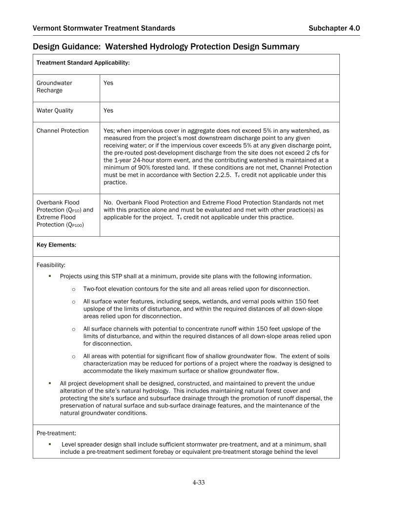
Vermont Stormwater Treatment Standards Subchapter 4.0
4-33
Treatment Standard Applicability:
Groundwater
Recharge
Yes
Water Quality Yes
Channel Protection Yes; when impervious cover in aggregate does not exceed 5% in any watershed, as
measured from the project’s most downstream discharge point to any given
receiving water; or if the impervious cover exceeds 5% at any given discharge point,
the pre-routed post-development discharge from the site does not exceed 2 cfs for
the 1-year 24-hour storm event, and the contributing watershed is maintained at a
minimum of 90% forested land. If these conditions are not met, Channel Protection
must be met in accordance with Section 2.2.5. Tv credit not applicable under this
practice.
Overbank Flood
Protection (QP10) and
Extreme Flood
Protection (QP100)
No. Overbank Flood Protection and Extreme Flood Protection Standards not met
with this practice alone and must be evaluated and met with other practice(s) as
applicable for the project. Tv credit not applicable under this practice.
Key Elements:
Feasibility:
▪ Projects using this STP shall at a minimum, provide site plans with the following information.
o Two-foot elevation contours for the site and all areas relied upon for disconnection.
o All surface water features, including seeps, wetlands, and vernal pools within 150 feet
upslope of the limits of disturbance, and within the required distances of all down-slope
areas relied upon for disconnection.
o All surface channels with potential to concentrate runoff within 150 feet upslope of the
limits of disturbance, and within the required distances of all down-slope areas relied upon
for disconnection.
o All areas with potential for significant flow of shallow groundwater flow. The extent of soils
characterization may be reduced for portions of a project where the roadway is designed to
accommodate the likely maximum surface or shallow groundwater flow.
▪ All project development shall be designed, constructed, and maintained to prevent the undue
alteration of the site’s natural hydrology. This includes maintaining natural forest cover and
protecting the site’s surface and subsurface drainage through the promotion of runoff dispersal, the
preservation of natural surface and sub-surface drainage features, and the maintenance of the
natural groundwater conditions.
Pre-treatment:
▪ Level spreader design shall include sufficient stormwater pre-treatment, and at a minimum, shall
include a pre-treatment sediment forebay or equivalent pre-treatment storage behind the level

Vermont Stormwater Treatment Standards Subchapter 4.0
4-34
spreader lip, that can easily be accessed by maintenance equipment with minimal resulting
disturbance following construction.
Treatment:
▪ There are two allowable approaches to manage road runoff: uncollected runoff shall be managed
under the “Disconnection Adjacent to Downhill Side of the Road” requirements, and collected runoff
from ditches shall be managed under “Disconnection via Level Spreader” requirements.
▪ Frequent cross-drainage shall be provided under roads. Each roadway section aligned across a
slope shall be constructed to provide for the passage of uphill surface flows under the roadway using
culverts, rock sandwiches, or other methods to convey flows to the down-slope side of the travel-way.
Unless otherwise required due to the presence of groundwater or other drainage features, the
distances between drainage structures shall be in accordance with Table 4-4. Stormwater runoff
from road surface shall not comingle with cross-drainage prior to treatment, accomplished by
“clean” conveyance on up-gradient side of roads and grading plan or equivalent method.
Other:
▪ The vegetative cover type of a disconnection must be either forest or meadow that is allowed to
regenerate to forest. In most instances the sizing of a disconnection varies depending on vegetative
cover type. The vegetative cover, including the duff layer, shall remain undisturbed with the
exception of necessary maintenance or repair, unless otherwise allowable below pertaining to
silvicultural activities.
▪ Silvicultural activities, including logging, are allowed provided the lands are under a forest
management plan approved by the Vermont Agency of Natural Resources, and provided the
activities are limited to harvesting in dry or winter conditions, with no construction of skidder trails,
roads, or landings.
Information contained in this table is for quick reference and is not inclusive of all requirements. All required
elements in this section shall be met in order for the STP to be in conformance with this Manual.

Vermont Stormwater Treatment Standards Subchapter 4.0
4-35
Structural Stormwater Treatment Practices
Bioretention
Bioretention practices capture and treat runoff from impervious areas by passing it through a vegetated filter bed,
with a filter mixture of sand, soil, and organic matter. Filtered stormwater is either returned to a conveyance
system or infiltrated into the native soil. Bioretention is a multi-functional practice that can be easily adapted for
new and redevelopment applications, for almost any land use. Stormwater runoff is stored temporarily and
filtered in landscaped practices shaped to take runoff from various sized impervious areas. Bioretention provides
water quality treatment and aesthetic value, and can be applied as concave parking lot islands, linear roadway or
median filters, terraced slope practices, residential cul-de-sac islands, and ultra-urban planter boxes.
One of the important design factors to consider in using bioretention is the scale at which it will be applied.
Bioretention can be sited as small, distributed practices designed to treat runoff from small areas such as individual
rooftops and driveways and are installed in native soils where infiltration can occur and without an underdrain
system. Bioretention practices can also be used to treat larger drainage areas such as parking lots in commercial or
institutional areas and where structural drainage design components are needed (e.g., underdrains, liners,
overflow drain inlets). In urban settings, bioretention structures are often incorporated in or retrofitted into tree
pits, curb extensions, and foundation planters.
Bioretention practices are well suited to be used in combination with Simple Disconnection (Section 4.2.2) and
Disconnection to Filter Strips and Vegetated Buffers (Section 4.2.3) when additional storage is necessary to meet
additional treatment standards.

Vermont Stormwater Treatment Standards Subchapter 4.0
4-36
Figure 4-9: Bioretention, Design Guidance

Vermont Stormwater Treatment Standards Subchapter 4.0
4-37
4.3.1.1. Bioretention Feasibility
Required Elements:
The bottom of the bioretention practice shall be located at or above the seasonal high groundwater table
(SHGWT).
If the bioretention practice is designed to infiltrate stormwater through the bottom of the practice into
underlying soils, the soils shall have an infiltration rate (fc) of at least 0.2 inches per hour, as confirmed by soil
testing requirements for infiltration pursuant to Section 4.3.3.2.
For bioretention practices designed to infiltrate stormwater, applicable feasibility required elements for
infiltration trench and basin practices shall also be met (Section 4.3.3). The separation to SHGWT requirements
identified in Section 4.3.3.1 are not applicable to bioretention practices designed to treat the water quality and
groundwater recharge volumes only.
Systems designed to infiltrate more than the WQV shall maintain a minimum 3-foot separation to SHGWT from
the bottom of the practice; unless contributing drainage area to the practice is less than or equal to 1 acre, then
there shall be a:
o Minimum 2 feet of separation to SHGWT from the bottom of the bioretention system when the
contributing drainage area (CDA) of 1 acre or less is greater than 50% impervious.
o Minimum 1 foot of separation to SHGWT from the bottom of the bioretention system when the
contributing drainage area (CDA) of 1 acre or less is less than or equal to 50% impervious.
Bioretention practices that are designed to infiltrate more than the 1-year, 24-hour storm event shall provide a
groundwater mounding analysis pursuant to Section 4.3.3.1.
Design Guidance:
Slopes of directly contributing areas should be low to moderate (generally 15% or less). If slopes are too steep
(e.g., greater than 8%), then level-spreading devices may be needed to redistribute flow prior to filtering. Filter
beds within bioretention practices should be flat or slightly sloping (generally 0.5% maximum). If slopes within
bioretention practice are too steep, then a series of check dams, terraces, or berms may be incorporated into the
design to maintain sheet flow internally.
Tree filters are small bioretention practices that may be contained in a concrete vault with an underdrain
connecting to the storm drain system, or may have an open base for infiltration into the underlying soils. All
other design criteria and guidance for tree filters are identical to bioretention practices, excepting pre-
treatment. Different methods of pre-treatment may need to be considered for severely constrained site
applications to ensure for water quality treatment, ease of maintenance, and practice longevity. Proprietary
tree filter designs may include some form of pre-treatment or other design element to ensure for ease of
maintenance and practice longevity that may be considered by the Agency for approval.
There are many other forested bioretention practice options, including structural soils and suspended
pavement, which can be designed to provide similar or greater stormwater treatment benefits. Such options are
often most feasible in urban retrofit and redevelopment situations, and designs incorporating these practices
are encouraged.
Additional guidance regarding rain gardens, which share similar design elements to traditional bioretention,
can be found in the Vermont Rain Garden Manual
(http://www.uvm.edu/seagrant/sites/default/files/uploads/publication/VTRainGardenManual_Full.pdf).

Vermont Stormwater Treatment Standards Subchapter 4.0
4-38
4.3.1.2. Bioretention Conveyance
Required Elements:
Runoff shall enter, flow through, and exit bioretention practices in a safe and non-erosive manner. Inflow may
be through depressed curbs or curb cuts or conveyed directly using downspouts, covered drainage pipes, or
catch basins.
If runoff is delivered by a storm drain pipe or is along the main conveyance system, the bioretention practice
shall be designed off-line. In these cases, a flow regulator or flow splitter diversion structure shall be supplied
to divert the WQV or TV to the filter practice, and allow larger flows to bypass the practice. If bypassing a
bioretention practice is impractical, an internal overflow device (e.g., elevated yard inlet) shall be used.
In cases where bioretention is designed as an on-line practice, an overflow shall be provided within the practice
to pass flows in excess of the WQV or TV to a stable conveyance. Designers shall indicate how on-line practices
will safely pass the 10-year storm without re-suspending or flushing previously trapped material.
To prevent erosion, an overflow for the 10-year storm shall be provided to a non-erosive outlet point.
The channel immediately below a bioretention system outfall shall be modified to prevent erosion and conform
to natural dimensions in the shortest possible distance, typically by use of appropriately sized riprap placed
over filter fabric. A stilling basin or outlet protection shall be used to reduce flow velocities from the principal
spillway to non-erosive velocities of 3.5 to 5.0 fps.
Stormwater from bioretention system outlets shall be conveyed to discharge location in non-erosive manner.
Underdrained bioretention practices shall be equipped with a minimum 6-inch perforated pipe underdrain (8
inches is preferred) in a minimum 1-foot deep stone layer. Within the stone layer the underdrain pipe shall be
separated by at least 3 inches from the bioretention media and 2 inches from the bottom of the practice.
Synthetic filter fabrics shall not be used to completely separate the filter media from the underdrain bedding
material.
Design Guidance:
Bioretention systems should be designed off-line whenever possible. A flow splitter should be used to divert
excess high flows away from the filter media to a stable conveyance.
Bioretention practices should be designed to completely drain or dewater within 48 hours (2 days) after a storm
event to reduce the potential for nuisance ponding conditions.
4.3.1.3. Bioretention Pre-Treatment
Pre-treatment of roof runoff is not required, provided the runoff is routed to the bioretention practice in a manner
such that it is unlikely to accumulate significant additional sediment (e.g., via closed pipe system or grass channel),
and provided the runoff is not commingled with other runoff. See Section 4.1 for specific pre-treatment practice
requirements and design guidance.
Required Elements:
If stormwater is routed to a forebay for required pre-treatment, the forebay shall be volumetrically sized for
25% of the computed WQV. Otherwise, required pre-treatment shall be designed in accordance with Section
4.1.

Vermont Stormwater Treatment Standards Subchapter 4.0
4-39
Design Guidance:
Pre-treatment devices used with bioretention, including sediment forebays, may be designed as level spreaders
such that inflows to the filter bed have near zero velocity and spread runoff evenly across the filter bed surface.
4.3.1.4. Bioretention Treatment
Required Elements:
A storage volume of at least 75% of the design TV including the volume over the top of the filter media and the
volume in the pretreatment chamber(s) as well as within the bioretention soil filter media – is required to
capture the volume from high-intensity storms prior to filtration and to avoid premature bypass.
If the cell ponding area uses vegetated soil, then the maximum side slope shall be 2.5:1. If the cell depth
exceeds 3 feet, the maximum side slope shall be 3:1. Rip-rap or concrete walls, or approved equivalent shall be
used if steeper side slopes are necessary.
Maximum ponding depth shall be no more than 12 inches above the surface of the filter bed; ponding depths
greater than 9 inches shall require that the landscaping plan addresses anticipated greater ponding depths to
ensure appropriate plant selection.
Bioretention systems shall consist of the following treatment components: a 24 to 48-inch deep planting soil
bed (depending on the requirements of proposed vegetation), a surface treatment that suppresses weed
growth, such as stone or other inert material that minimizes exposed soil, and a 6 to 12-inch deep surface
ponding area. Plantings may be mulched as necessary. Soils shall consist of USDA sand to loamy sand
classification and meet the following gradation: sand 85- 88%, silt 8-12%, clay 0-2%, and organic matter in the
form of compost 3-5%.
The designer shall identify on the plan sheet that a soil phosphorus test using the Morgan Method, or approved
equivalent, is required for practices with underdrains, to ensure that bioretention soil media will not leach
phosphorus. The “available phosphorus” for the soil must be less than 0.2% phosphorus. The plan shall also
identify that the record of the phosphorus test shall be maintained with design or permit records for
subsequent design certification requirements.
The filter area for bioretention shall be sized based on the principles of Darcy’s Law. A coefficient of
permeability (k) should be used as follows:
Bioretention Soil: 1.0 feet per day for sandy loam soils
(Note: the above value is conservative to account for clogging associated with accumulated sediment)
The bioretention filter bed area shall be computed using the following equation:
𝐴𝑓 =
(𝑇𝑣)(𝑑𝑓)
(𝑘)(ℎ𝑓 + 𝑑𝑓)(𝑡𝑓) Equation 4-2
where:
Af = Surface area of filter bed (ft2)
TV = Treatment volume (ft3)
df = Filter bed depth (ft)
k = Coefficient of permeability of filter media (ft/day)
hf = Average height of water above filter bed (ft)
Vermont Stormwater Treatment Standards Subchapter 4.0
4-40
tf = Design filter bed drain time (days)
(2 days is the recommended maximum tf for bioretention)
For infiltrating bioretention systems, credit toward WQV, CPV, QP10, and QP100 shall be based on the treatment
volume provided.
For bioretention practices used primarily for filtering (e.g., underdrained), credit towards CPV, QP10, and QP100
shall be given only for the void space in the stone sump beneath the underdrain.
Bioretention practices shall not be lined unless required due to hotspot land use or other site specific factors,
subject to Agency approval.
Design Guidance:
A mulch layer of shredded hardwood that is well aged (stockpiled or stored for at least 6 months) should be
applied to a maximum depth of 3 inches. Hardwood mulch can be challenging to obtain in New England.
Acceptable alternatives include use of softwood mulch, or equivalent alternative, and mulching only around
shrubs, and planting a conservation mix elsewhere to create a cover crop that can be mowed or weed-whacked;
or planting two species of tall grasses and allowing the whole STP to fill in. A stone surface may also be
considered in place of a mulch layer. Regardless of the surface treatment chosen, it should outcompete or
suppress weed growth, and minimize exposed soil. Erosion control blankets installed across the bottom of the
practice are generally not successful and should not be proposed.
Filter beds should be extended below the frost line to prevent the filtering medium from freezing during the
winter, or filtering treatment can be combined with another stormwater treatment practice option that can be
used as a backup to the filtering system to provide treatment during the winter when the filter bed is frozen.
4.3.1.5. Bioretention Vegetation and Landscaping
Required Elements:
The entire contributing area shall be stabilized before runoff may be directed into a filtration practice. A dense
and vigorous vegetative cover shall be established over the contributing pervious drainage areas, and
impervious area construction must be completed.
A landscaping plan that provides soil stabilization and nutrient uptake shall be provided for bioretention areas.
Design Guidance:
Planting recommendations for bioretention facilities are as follows:
Native plant species should be specified over non-native species, though non-invasive cultivars are also
acceptable and can provide the functions needed for a successful bioretention system.
Vegetation should be selected based on a specified zone of hydric tolerance.
A selection of trees with an understory of shrubs and herbaceous materials should be provided.
Woody vegetation should not be specified at inflow locations.
Trees should be planted primarily along the perimeter of the STP.
A tree density of approximately one tree per 100 square feet (i.e., 10 feet on-center) is recommended. Shrubs
and herbaceous vegetation should generally be planted at higher densities (five feet on-center and 2.5 feet on
center, respectively).

Vermont Stormwater Treatment Standards Subchapter 4.0
4-41
Treatment Standard Applicability:
Groundwater
Recharge
Yes. (if designed for infiltration)
Water Quality Yes. Tier 1 Practice (designed for infiltration) / Tier 2 Practice (underdrained and/or
lined)
Channel Protection Limited. Hydrologic Condition Method (designed for infiltration) / Extended Detention
Method (underdrained and/or lined)
Overbank Flood
Protection (QP10) and
Extreme Flood
Protection (QP100)
Limited. CNAdj may provide partial credit for volume infiltrated (Tv) or available
storage volume in sump.
Key Elements:
Feasibility:
▪ Infiltration rate shall be ≥0.2 inches per hour as confirmed by methods in Section 4.3.3.2 if designed
for infiltration.
▪ SHGWT must be below bottom of the practice for Water Quality Treatment Standard. Separation to
SHGWT for larger storm events varies based size of practice and volume designed to infiltrate.
Pre-treatment:
▪ Forebay sized for 25% of the WQV or other pre-treatment in Section 4.1
Treatment:
▪ Filter bed shall be 24-48 inches deep. If underdrained, the “available phosphorus” for the
bioretention soil filter media must be less than 0.2% phosphorus.
▪ Maximum ponding depth of 12 inches.
▪ Volume storage within practice, including pore space and ponding depth, is credited towards WQV.
For infiltrating practices, this same treatment volume is applied to CPV, QP10, and QP100. For
underdrained practices, HCV is limited to pore space below underdrain.
▪ Volume, including pre-treatment shall be a minimum of 75% the TV.
Other:
▪ Minimum 6-inch diameter perforated pipe underdrain shall be provided if not designed to infiltrate.
▪ Landscaping plan shall be provided.
Information contained in this table is for quick reference and is not inclusive of all requirements. All required
elements in this section shall be met in order for the STP to be in conformance with this Manual.

Vermont Stormwater Treatment Standards Subchapter 4.0
4-42
Dry Swales
A bioswale or dry swale is essentially a bioretention cell that is shallower, configured as a linear channel, and
covered with turf or surface material other than mulch and ornamental plants. The dry swale is a soil filter system
that temporarily stores and then filters a desired runoff volume for treatment. Dry swales rely on a pre-mixed soil
media filter below the channel surface. If the native soils are permeable, runoff infiltrates into underlying soils.
Otherwise, the runoff treated by the soil media flows into an underdrain, which conveys treated runoff further
downstream or safely daylights down-gradient. The underdrain system typically consists of a perforated pipe
within a stone layer on the bottom of the swale, beneath the filter media.
Figure 4-10. Dry Swale, Design Guidance

Vermont Stormwater Treatment Standards Subchapter 4.0
4-43
4.3.2.1. Dry Swale Feasibility
Required Elements:
Dry swales constructed without check dams shall have a maximum longitudinal slope of 5%. Open channels
constructed on steeper slopes, to a maximum longitudinal slope of 6%, shall include check dams, step pools, or
other grade controls.
The bottom of a dry swale shall be located at or above the seasonal high groundwater table (SHGWT).
If the dry swale is designed to infiltrate stormwater through the bottom of the practice into underlying soils,
the native soils shall have an infiltration rate (fc) of at least 0.2 inches per hour, as confirmed by soil testing
requirements for infiltration pursuant to Section 4.3.3.2
Dry swales designed to infiltrate more than the WQV shall maintain a minimum 3-foot separation to SHGWT
from the bottom of the practice; unless the contributing drainage area to the practice is less than or equal to 1
acre, then there shall be a:
o Minimum of 2 feet separation to SHGWT from the bottom of the dry swale system when the
contributing drainage area (CDA) of 1 acre or less is greater than 50% impervious.
o Minimum of 1 foot separation to SHGWT from the bottom of the dry swale system when the
contributing drainage area (CDA) of 1 acre or less is less than or equal to 50% impervious.
Design Guidance:
Steeper slopes may increase velocity and the potential for erosion within the swale, and sediment deposition
may be reduced. Check dams, step pools, or other grade controls can be used to lengthen the contact time to
enhance filtering and/or infiltration. Steeper slopes adjacent to the swale may generate rapid runoff velocities
into the swale that may carry a high sediment loading, requiring additional pre-treatment consideration.
Dry swale footprints can fit into relatively narrow corridors between utilities, roads, parking areas, or other site
constraints.
Swale location should be considered carefully. Swales along roadways may be damaged by off-street parking
and plowing and sanding in the winter. The choice of vegetation and landscaping can be limited in adjacent
areas.
4.3.2.2. Dry Swale Conveyance
Required Elements:
The maximum allowable temporary ponding time within a channel shall be less than 48 hours. For dry swales,
if the infiltrative capacity of the underlying native soils is less than 0.2 inches per hour, an underdrain system
shall be used to ensure this requirement is met.
Underdrained dry swale practices shall be equipped with a minimum 6-inch perforated pipe underdrain (8
inches is preferred) in a minimum 1-foot deep stone layer. Within the stone layer the underdrain pipe shall be
separated by at least 3 inches from the filter media and 2 inches from the bottom of the practice. Synthetic filter
fabrics shall not be used to completely separate the filter media from the underdrain bedding material.
The peak velocity for the 1-year storm shall be non-erosive, in other words 3.5-5 feet per second.
The swale shall have the capacity to convey the 10-year 24-hour storm event, at a minimum, safely with 6
inches of freeboard.

Vermont Stormwater Treatment Standards Subchapter 4.0
4-44
The channel immediately below a dry swale outfall shall be modified to prevent erosion and conform to
natural dimensions in the shortest possible distance, typically by use of appropriately sized riprap placed over
filter fabric. stilling basin or outlet protection shall be used to reduce flow velocities from the principal
spillway to non-erosive velocities of 3.5 to 5.0 fps.
Stormwater from dry swale outlets shall be conveyed to discharge location in non-erosive manner.
Dry swales shall have a trapezoidal or parabolic cross section with side slopes less than or equal to 2H:1V.
The longitudinal channel slope shall be less than or equal to 5.0%. If the site slope is greater than 5%,
additional measures such as check dams shall be utilized to retain the water quality volume within the swale
system.
Check Dams. Check dams or weirs shall be used to increase hydraulic residence time in the swale in steeper
applications. Plunge pools or other energy dissipation may also be required where the elevation difference
between the tops of weirs to the downstream channel invert is a concern. The design requirements for check
dams are as follows:
o Check dams shall be composed of wood, concrete, stone, or other non-erodible material. The check
dam shall be designed to facilitate easy mowing.
o Check dams shall be firmly anchored into the side-slopes to prevent outflanking and anchored into
the channel bottom a minimum of 6 inches.
o Armoring shall be provided at the downstream toe of the check dam, if necessary, to prevent
erosion.
o Check dams shall be spaced based on channel slope, as needed, to increase residence time, provide
storage volume, or meet volume attenuation requirements. The ponded water at a downhill check
dam shall not extend above the elevation of the toe of the upstream check dam.
o Check dams composed of wood, concrete, or similar construction, shall have a weep hole or similar
drainage feature so the check dam can dewater after a storm event.
Design Guidance:
Open channel systems may be designed as off-line systems to reduce erosion during large storm events, or may
be designed to accommodate larger events with overflow or other outlet configuration.
To prevent culvert freezing, use culvert pipes with a minimum diameter of 18 inches, and design culverts with
a minimum 1% slope.
4.3.2.3. Dry Swale Pre-Treatment
Required Elements:
If stormwater is routed to a forebay for required pre-treatment, the forebay shall be volumetrically sized for
10% of the computed WQV. Otherwise, required pre-treatment shall be designed in accordance with Section
4.1.
Design Guidance:
The storage volume for pre-treatment may be obtained by providing check-dams or berms at pipe inlets and/or
driveway/road crossings, consistent with pre-treatment sediment forebay requirements.
Road drainage entering a swale along the length of the road may pre-treat runoff using a vegetated filter strip.

Vermont Stormwater Treatment Standards Subchapter 4.0
4-45
4.3.2.4. Dry Swale Treatment
Required Elements:
A dry swale storage volume of at least 75% of the design TV, including the volume over the top of the filter
media and the volume in the pre-treatment practice(s), as well within the bioretention soil filter media – is
required in order to capture the volume from high-intensity storms prior to filtration and to avoid premature
bypass.
For infiltrating dry swales, credit toward WQV, CPV, QP10, and QP100 shall be based on the treatment volume
provided. For underdrained and lined practices, HCV credit is limited to pore space in the stone sump.
Dry swales shall consist of the following treatment components: a 24 to 48-inch deep filter bed, a surface
vegetation or mulch layer, and no more than a 12-inch deep average surface ponding depth. Soil media shall
either consist of a medium sand (meeting ASTM C- 33 concrete sand) or meet the specifications outlined for
bioretention areas (Section 4.3.1).
The designer shall identify on the plan sheet that a soil phosphorus test using the Morgan Method, or approved
equivalent, is required for dry swale practices using a bioretention soil mix with underdrains, to ensure that the
dry swale soil media will not leach phosphorus. The “available phosphorus” for the soil must be less than 0.2%
phosphorus. The plan shall also identify that the record of the phosphorus test shall be maintained with design
or permit records for subsequent design certification requirements.
The minimum filter area for dry swales shall be sized based on the principles of Darcy’s Law. A coefficient of
permeability (k) shall be used as follows:
o Bioretention soil mix: 1.0 ft/day for sandy loam soils
o Sand: 3.5 ft/day
(Note: the above values are conservative to account for clogging associated with accumulated
sediment)
The dry swale filter bed area is computed using the following equation:
𝐴𝑓 =
(𝑇𝑣)(𝑑𝑓)
(𝑘)(ℎ𝑓 + 𝑑𝑓)(𝑡𝑓) Equation 4-3
where:
Af = Surface area of filter bed (ft2)
TV = design treatment volume (e.g., WQV or HCV) (ft3)
df = Filter bed depth (ft)
k = Coefficient of permeability of filter media (ft/day)
hf = Average height of water above filter bed (ft)
tf = Design filter bed drain time (days)
(2 days is the recommended maximum tf for bioretention)
Swales shall have a bottom width between 2 and 8 feet. If a swale will be wider than 8 feet, the designer should
incorporate berms, check dams, level spreaders, or multi-level cross-sections to prevent braiding and erosion of
the swale bottom.
Dry swales shall not be lined unless required due to hotspot land use or other site specific factors, subject to
Agency approval.

Vermont Stormwater Treatment Standards Subchapter 4.0
4-46
Design Guidance:
Open channels should maintain a maximum ponding depth of 1 foot at the longitudinal mid-point of the
channel, and a maximum depth of 18 inches at the end point of the channel (for head/storage of the WQV).
The coefficient of permeability of filter media, ‘k’, is independent from the underlying soil infiltration rate,
however may be comparable when filter media is consistent with or will utilize native underlying soils.
4.3.2.5. Dry Swale Vegetation and Landscaping
Required Elements:
The entire contributing area shall be stabilized before runoff may be directed into the practice. A dense and
vigorous vegetative cover shall be established over the contributing pervious drainage areas, and impervious
area construction must be completed.
A thick vegetative cover shall be provided for proper function.
A landscaping plan that provides soil stabilization and nutrient uptake shall be provided for both wet and dry
swales. For dry swales that are intended to be mowed, a seed specification and seeding rate may take the place
of the landscaping plan.
Design Guidance:
Planting recommendations for dry swales are as follows:
Native plant species should be specified over non-native species, though non-invasive cultivars are also
acceptable and can provide the functions needed.
The landscaping plan should specify proper grass species and emergent plants based on specific site, soils, and
hydric conditions present along the proposed swale.
Wet swales are not acceptable for meeting the Water Quality Treatment Standard, however may be a
component of stormwater conveyance to the dry swale STP which may be located at the end of the conveyance.
Wet swales typically cannot accommodate a filter bed as required by the dry swale requirements and may
sustain a permanent pool during most of the year due to seasonally high groundwater or soil conditions.
Treatment Standard Applicability:
Groundwater
Recharge
Yes. (if designed for infiltration)
Water Quality Yes. Tier 1 Practice (designed for infiltration) / Tier 3 Practice (underdrained and/or
lined)
Channel Protection Limited. Hydrologic Condition Method (designed for infiltration)/ Extended Detention
Method (underdrained and/or lined)

Vermont Stormwater Treatment Standards Subchapter 4.0
4-47
Overbank Flood
Protection (QP10) and
Extreme Flood
Protection (QP100)
Limited. CNAdj may provide partial credit for volume infiltrated (Tv) or available
storage volume in sump.
Key Elements:
Feasibility:
▪ Maximum longitudinal slope of 5% without check dams. Slopes up to 6% allowed with check dams.
▪ Maximum side slopes of 2:1.
▪ Infiltration rate shall be ≥0.2 inches per hour as confirmed by methods in Section 4.3.3.2 if designed
to infiltrate.
▪ SHGWT must be below bottom of the practice for Water Quality Treatment Standard. Separation to
SHGWT for larger storm events varies based size of practice and volume designed to infiltrate.
Pre-treatment:
▪ Forebay sized for 10% of the WQV or other pre-treatment as described in Section 4.1
Treatment:
▪ Swale is underlain with a sand or filter media mix. If underdrained, the “available phosphorus” for
the soil filter media must be less than 0.2% phosphorus.
▪ Volume storage within practice, including pore space and ponding depth, is credited towards WQV.
For infiltrating practices, this same treatment volume is applied to CPV, QP10, and QP100. For
underdrained practices, HCV is limited to pore space below underdrain.
▪ Volume, including pre-treatment shall be a minimum of 100% the TV.
▪ Maximum dewatering time of 48 hours.
Other:
▪ Minimum 6-inch diameter perforated pipe underdrain shall be provided if not designed to infiltrate.
▪ Landscaping plan shall be provided.
Information contained in this table is for quick reference and is not inclusive of all requirements. All required
elements in this section shall be met in order for the STP to be in conformance with this Manual.

Vermont Stormwater Treatment Standards Subchapter 4.0
4-48
Infiltration Trenches and Basins
Stormwater infiltration practices capture and store stormwater runoff, for the express purpose of allowing it to
infiltrate into the soil. Structural infiltration practices can be used to meet the Groundwater Recharge Standard and
Water Quality Treatment Standard, and when designed to accommodate larger volumes can be used to meet the
Channel Protection Standard, and larger flood control standards. Infiltration STPs can provide groundwater
recharge as well as reduce the volume of stormwater runoff entering the drainage system and reduce or slow peak
flows. Infiltration practices reduce pollutants and total suspended solids via physical filtering of the runoff
through a media (most often soil), as well as chemical and biological activity within the media. Infiltration
practices, including dry wells and underground storage chambers, that are properly sited and constructed in
accordance with this Manual will not be required to obtain a separate permit under the Underground Injection
Control Rules. Designers should review the infiltration feasibility requirements for structural infiltration systems
related to set backs from groundwater source protection and wastewater disposal systems, and consult with the
Agency’s Drinking Water and Groundwater Protection Division in advance of designing a structural infiltration
STP.
In some cases, infiltration practices can provide extended detention or infiltration for channel protection and for
overbank or extreme flood storm events on sites with high soil infiltration rates. Extraordinary care should be
taken to ensure that long-term infiltration rates are achieved through the use of proper pre-treatment, post-
construction inspection, and routine, long-term maintenance.

Vermont Stormwater Treatment Standards Subchapter 4.0
4-49
Figure 4-11. Infiltration Trench, Design Guidance

Vermont Stormwater Treatment Standards Subchapter 4.0
4-50
4.3.3.1. Infiltration Feasibility
Required Elements:
Underlying soils shall have an infiltration rate (fc) of at least 0.2 inches per hour, as documented by soil testing
requirements for infiltration pursuant to Section 4.3.3.2.
The bottom of the infiltration practice shall be separated by at least 3 feet vertically from the seasonal high
groundwater table (SHGWT) or bedrock layer, as documented by on-site soil testing. For dry wells with less
than or equal to 1,000 square feet of contributing residential rooftop runoff, vertical separation to SHGWT shall
be a minimum of 1 foot.
Infiltration practices that are designed to infiltrate more than the 1-year, 24-hour storm event and that have a
separation from the bottom of the practice to SHGWT of less than 4 feet shall provide a groundwater
mounding analysis based on the Hantush Method, or equivalent, to demonstrate that the required vertical
separation distance between the bottom of the practice and SHGWT can be maintained during and following
the design storm.
Infiltration basins shall have vegetated side slopes of 2:1 or flatter.
The following set back requirements shall be observed for groundwater source protection:
o 100 feet set back from source in bedrock or confined unconsolidated aquifers.
o 150 feet set back from source in unconsolidated soils or unconfined unconsolidated aquifers.
o No structural infiltration STP sited within Zone 1 or Zone 2 of a public community groundwater
source protection area.
o No structural infiltration STP sited within 200 feet of non-transient non-community groundwater
source.
o Designers shall refer to the Vermont Wastewater and Potable Water Supply Rules, or their
replacement, for all applicable restrictions.
Infiltration practices shall not be placed in locations that cause water intrusion problems for down-gradient
structures. Infiltration practices shall be set back 75 feet down-gradient wastewater disposal areas systems, 35
feet up-gradient of wastewater disposal systems, and 75 feet down-gradient of wastewater disposal systems, or
as otherwise required by the Vermont Wastewater and Potable Water Supply Rules, or their replacement.
Infiltration practices shall not be used where subsurface contamination is present from prior land use due to
the increased threat of pollutant migration associated with increased hydraulic loading from infiltration
systems, unless contaminated soil is removed and the site remediated, or if approved by the Agency on a case-
by-case basis. On redevelopment sites, applicants are responsible for identifying potential contamination prior
to submitting an application.
Infiltration practices shall not be used for snow storage, as traction sand used in winter maintenance can cause
clogging and failure of the practices.
Design Guidance:
The maximum contributing area to dry wells, an acceptable form of an infiltration practice, should generally be
less than one acre, and include rooftop runoff only. The maximum contributing area for trenches should
generally be less than 5 acres. Infiltration basins or chamber systems can typically receive runoff from larger
contributing areas, provided that the soil is highly permeable, and adequate pre-treatment and maintenance
access is provided.

Vermont Stormwater Treatment Standards Subchapter 4.0
4-51
Infiltration practices should not be hydraulically connected to structure foundations or pavement to avoid
seepage and frost heave concerns, respectively.
4.3.3.2. Soil Testing Requirements for Infiltration Practices
4.3.3.2.1. Introduction
For structural infiltration-based practices including infiltration trenches and infiltration basins, permeable
pavements, dry wells, and bioretention and dry swales designed to infiltrate, a minimum field infiltration rate
(fc) of 0.2 inches per hour shall be required. Areas yielding a lower infiltration rate preclude the design of these
practices as infiltration systems.
4.3.3.2.2. Infiltration Feasibility Analysis
A feasibility analysis shall be completed to determine whether full-scale infiltration testing is necessary, and is
meant to screen unsuitable sites and reduce testing costs.
The infiltration feasibility analysis shall be representative of all variable site conditions present and the location
evaluated for infiltrating, and be based on one or more of the following:
NRCS Soil Survey mapping.
Test pit(s) or soil boring(s).
Previous written geotechnical reporting on the site location, as prepared by a qualified geotechnical consultant
If the results of the initial feasibility analysis indicate an infiltration rate of less than 0.2 inches per hour is probable,
or the presence of a HSG D soil in the applicable areas of investigation, then no further analysis is necessary. If the
results of initial feasibility testing indicate that an infiltration rate of greater than or equal to 0.2 inches per hour is
probable and infiltration is otherwise considered feasible by any other requirement in this Manual, then the
designer shall proceed with the soil characterization and infiltration testing requirements Sections 4.3.3.2.3 through
4.3.3.2.5.
4.3.3.2.3. Soil Characterization and Infiltration Testing
The number of test pits and infiltration tests shall be:
o For infiltration practices, 1 infiltration test and 1 test pit per 2,500 square feet of proposed practice
area, or
o For linear infiltration practices, 1 infiltration test and 1 test pit per 100 feet of proposed practice
length.
The location of the test pit or boring shall correspond to the STP location;
4.3.3.2.4. Test Pit Requirements
Designer shall excavate a test pit or dig a standard soil boring to a depth of at least 1 foot below the required
separation depth to the SHGWT of the proposed STP.
The designer’s soil descriptions shall include USDA or Unified Soil Classification System textures for all soil
horizons. Soil profile descriptions shall be provided consistent with the Vermont Wastewater System and
Potable Water Supply Rules, §1-902(b)(2) and Appendix 2-A, or their replacement.
The designer shall verify that the depth to groundwater table and the depth to bedrock meet the separation
distance required of the proposed practice.

Vermont Stormwater Treatment Standards Subchapter 4.0
4-52
4.3.3.2.5. Infiltration Testing Requirements
Field infiltration test methods to assess saturated hydraulic conductivity shall simulate the "field-saturated"
condition (see ASTM D5126-90 Standard Guide for Comparison of Field Methods for Determining Hydraulic Conductivity
in the Vadose Zone). Infiltration tests shall be conducted at the depth of the bottom of the proposed infiltrating
practice. Design infiltration rates shall be determined by using a factor of safety of 2 from the field-derived value.
Percolation tests shall not be used in place of testing for saturated hydraulic conductivity, as they overestimate
saturated hydraulic conductivity values. One or more of the following methods shall be used:
Guelph permeameter - ASTM D5126-90 Method
Falling head permeameter – ASTM D5126-90 Method
Double ring permeameter or infiltrometer - ASTM D3385-09, D5093-02, D5126-90 Methods
Amoozemeter or Amoozegar permeameter – Amoozegar 1992
Borehole Infiltration Test as described below:
o Install casing (solid 6-inch diameter) to 24 inches below proposed practice bottom.
o Remove any smeared soiled surfaces and provide a natural soil interface into which water may
percolate. Remove all loose material from the casing. Upon the tester’s discretion, a 2-inch layer of
coarse sand or fine gravel may be placed to protect the bottom from scouring and sediment. Fill
casing with clean water to a depth of 24 inches and pre-soak for 24 hours.
o 24 hours later, refill casing with another 24 inches of clean water and monitor water level
(measured drop from the top of the casing) for 1 hour. Repeat this procedure, filling the casing
each time 3 additional times, for a total of 4 observations. Upon the tester’s discretion, the final
field rate may either be the average of the 4 observations, or the value of the last observation. All
observations shall be reported. The final rate shall be reported in inches per hour.
o This test may be completed in a soil boring or in an open excavation.
o Upon completion of the testing, the casings shall be immediately pulled, and the test pit back-
filled.
Equivalent method approved by the Agency.
4.3.3.3. Infiltration Conveyance
Required Elements:
Flow velocities of surface runoff exceeding the capacity of the infiltration system shall be evaluated against
erosive velocities during the overbank events. If computed flow velocities exceed erosive velocities of 3.5-5.0
ft/s for the 1-year storm event, an overflow channel to a stable conveyance or level spreader shall be provided.
If a level spreader is provided, it shall be designed consistent with the requirements in the Disconnection to
Filter Strips and Vegetated Buffers practice standard (Section 4.2.3).
For infiltration practices, adequate outfall protection shall be provided for the overflow associated with larger
storm events, the 1-year, 10-year, and 100-year design storm events, as applicable.
Stormwater from infiltration system overflow shall be conveyed to discharge location in non-erosive manner.
All infiltration systems shall be designed to fully de-water the treatment volume (TV) within 48 hours after the
storm event.
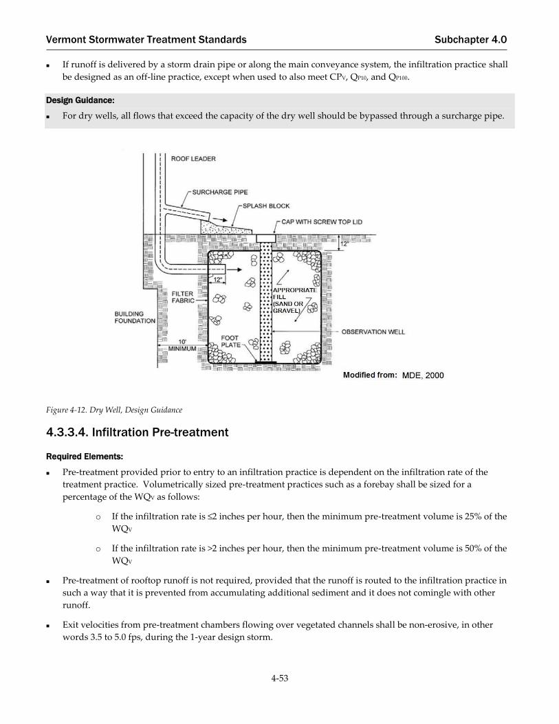
Vermont Stormwater Treatment Standards Subchapter 4.0
4-53
If runoff is delivered by a storm drain pipe or along the main conveyance system, the infiltration practice shall
be designed as an off-line practice, except when used to also meet CPV, QP10, and QP100.
Design Guidance:
For dry wells, all flows that exceed the capacity of the dry well should be bypassed through a surcharge pipe.
Figure 4-12. Dry Well, Design Guidance
4.3.3.4. Infiltration Pre-treatment
Required Elements:
Pre-treatment provided prior to entry to an infiltration practice is dependent on the infiltration rate of the
treatment practice. Volumetrically sized pre-treatment practices such as a forebay shall be sized for a
percentage of the WQV as follows:
o If the infiltration rate is ≤2 inches per hour, then the minimum pre-treatment volume is 25% of the
WQV
o If the infiltration rate is >2 inches per hour, then the minimum pre-treatment volume is 50% of the
WQV
Pre-treatment of rooftop runoff is not required, provided that the runoff is routed to the infiltration practice in
such a way that it is prevented from accumulating additional sediment and it does not comingle with other
runoff.
Exit velocities from pre-treatment chambers flowing over vegetated channels shall be non-erosive, in other
words 3.5 to 5.0 fps, during the 1-year design storm.

Vermont Stormwater Treatment Standards Subchapter 4.0
4-54
Infiltration basins or trenches shall have robust pre-treatment methods to ensure the long-term integrity of the
infiltration rate. This shall be achieved by using one or more of the following options (see Section 4.1 for
pretreatment design requirements):
o Pre-treatment swale (grass channel)
o Vegetated filter strip
o Sediment forebay separated at least 3 feet vertically from the SHGWT if located over permeable
soils.
o Deep sump catch basin, AND one of the following:
▪ Upper sand layer (6 inches minimum with filter fabric at the sand/gravel interface); or
▪ Washed stone (1/8 inch to 3/8 inch)
o Proprietary device
Provide a fixed vertical sediment marker to measure depth of accumulated sediment.
4.3.3.5. Infiltration Treatment
Required Elements:
Infiltration practices shall be designed to exfiltrate the entire TV and sized using TR-20 or approved equivalent
method.
An observation well shall be installed in every infiltration trench, dry well, and subsurface infiltration system
consisting of an anchored 4- to 6-inch diameter perforated PVC pipe with a screw-top cap or equivalent
installed flush with the ground surface. Observation wells shall be installed every 50 feet or as otherwise
required by manufacturers specifications.
Direct access shall be provided to infiltration practices for maintenance and rehabilitation.
Design Guidance:
The surface area of infiltration trenches may be calculated using following equation:
Ap =Tv
ndt + fcT/12
Where: Ap = practice surface area (ft2)
TV = design treatment volume (e.g., WQV, CPV, or QP) (ft3)
n = porosity (assume 0.33)
dt = trench depth (feet), maximum of four feet and separated from SHGWT as required
fc = design infiltration rate (in/hr) (i.e. soils below floor of practice)
T = time to fill trench (hours), assumed to be 2 hours for design purposes
The approximate bottom area of trapezoidal infiltration basins may be calculated using the following equation:
Ab =2Tv − Atdb
db − (P/6) + (fcT/6)
Equation 4-4
Equation 4-5

Vermont Stormwater Treatment Standards Subchapter 4.0
4-55
Where:
Ab = surface area at the bottom of the basin (ft2)
TV = design treatment volume (e.g., WQV, CPV, QP)(ft3)
At = surface area at the top of the basin (ft2)
db = depth of the basin (feet), separated from seasonal high groundwater as required
P = design rainfall depth (inches)
fc = design infiltration rate (inches/hour) (i.e. soils below floor of practice)
T = time to fill basin (hours), assumed to be 2 hours for design purposes
The design treatment volume of manufactured infiltration chambers may be calculated using the following
equation:
Tv = L [(wdn) − (XAcn) + (XAc) + (wfcT
12)]
Where:
TV = design treatment volume (e.g., WQV, CPV, or QP) (ft3)
L = length of infiltration STP (feet)
w = width of infiltration STP (feet)
d = depth of infiltration STP (feet), separated from SHGWT as required
X = number of rows of chambers
Ac = cross-sectional area of chamber (ft2), see manufacturer’s specifications
n = porosity (assume 0.33)
fc = design infiltration rate (inches/hour)
T = time to fill chambers (hours), assumed to be 2 hours for design purposes
Infiltration practices are best used in conjunction with other practices, and downstream detention is often
needed to meet the CPV and QP sizing criteria, where required.
The bottom of all infiltration practices should be flat, in order to enable even distribution and infiltration of
stormwater. The longitudinal slope should range only from the ideal 0% up to 1%, and the lateral slope should
be held at 0%.
The sides of infiltration trenches and dry wells should be lined with an acceptable filter fabric that prevents soil
piping.
In infiltration trench designs, a fine gravel or sand layer above the coarse stone treatment reservoir may be
incorporated to serve as a filter layer.
The bottom of the stone reservoir should be completely flat so that runoff will be able to infiltrate through the
entire surface.
Infiltration basins requiring embankments should follow the general design guidelines for ponds when
considering side slopes, riser location, and other important features.
Equation 4-6

Vermont Stormwater Treatment Standards Subchapter 4.0
4-56
Figure 4-13. Infiltration Basin, Design Guidance

Vermont Stormwater Treatment Standards Subchapter 4.0
4-57
Figure 4-14. Underground Infiltration Chambers, Design Guidance
4.3.3.6. Infiltration Vegetation and Landscaping
Required Elements:
Contributing drainage areas shall be stabilized before runoff can be routed into the practice.
Landscape design shall specify proper grass or plant species based on the specific site and soil conditions
present in the practice to stabilize soils and provide nutrient uptake.
Design Guidance:
The selection of upland landscaping materials should include native plants and grasses where appropriate.
Treatment Standard Applicability:
Groundwater
Recharge
Yes
Water Quality Yes. Tier 1 Practice

Vermont Stormwater Treatment Standards Subchapter 4.0
4-58
Channel Protection Yes, Hydrologic Condition Method / Extended Detention Method in consideration of
volumes routed to outlet structure above infiltration design volume.
Overbank Flood
Protection (QP10) and
Extreme Flood
Protection (QP100)
Limited, Hydrologic Condition Method. Partial credit through CNAdj.
Key Elements:
Feasibility:
▪ Infiltration rate shall be ≥0.2 inches per hour as confirmed by methods in Section 4.3.3.2.
▪ SHGWT must be at least 3 feet below the bottom of the infiltration basin, trench, or chambers.
Drywells shall have a separation of at least 1 foot from the SHGWT.
▪ Setbacks required for groundwater source protection and wastewater disposal systems.
▪ May not be allowable on sites considered to be stormwater hotspots.
Pre-treatment:
▪ Forebay:
o For infiltration rates ≤ 2 inches per hour sized for 25% of the WQV.
o For infiltration rates >2 inches per hour, sized for 50% of the WQV.
▪ Other pre-treatment practice as described in Section 4.1
Treatment:
▪ System shall be designed to infiltrate the TV. Design TV may be subtracted from the ReV and WQV. The
TV may also be credited towards the CPV, QP10, and QP100 through the Hydrologic Condition Method of
the Channel Protection Standard.
▪ Observation wells shall be installed at least every 50 feet of practice length for infiltration trenches,
dry wells, and subsurface infiltration systems, or as required by the manufacturer.
Other:
▪ Landscaping plan shall be provided.
Information contained in this table is for quick reference and is not inclusive of all requirements. All required
elements in this section shall be met in order for the STP to be in conformance with this Manual.

Vermont Stormwater Treatment Standards Subchapter 4.0
4-59
Filtering Systems
Stormwater filtering systems capture and temporarily store the TV and pass it through a filter bed of sand or
augmented media. Filtered runoff may be collected and returned to the conveyance system, or allowed to partially
exfiltrate into the soil. Design variants include:
Surface Sand Filter
Underground Sand Filter
Perimeter Sand Filter
Alternative, Augmented, or Proprietary Media Filter (See Alternative Stormwater Treatment Practices for
approval requirements, Section 4.4)
Filtering systems should not be designed to provide channel protection or stormwater detention except under
extremely unusual conditions. Filtering practices should generally be combined with a separate STP to provide
quantity controls.
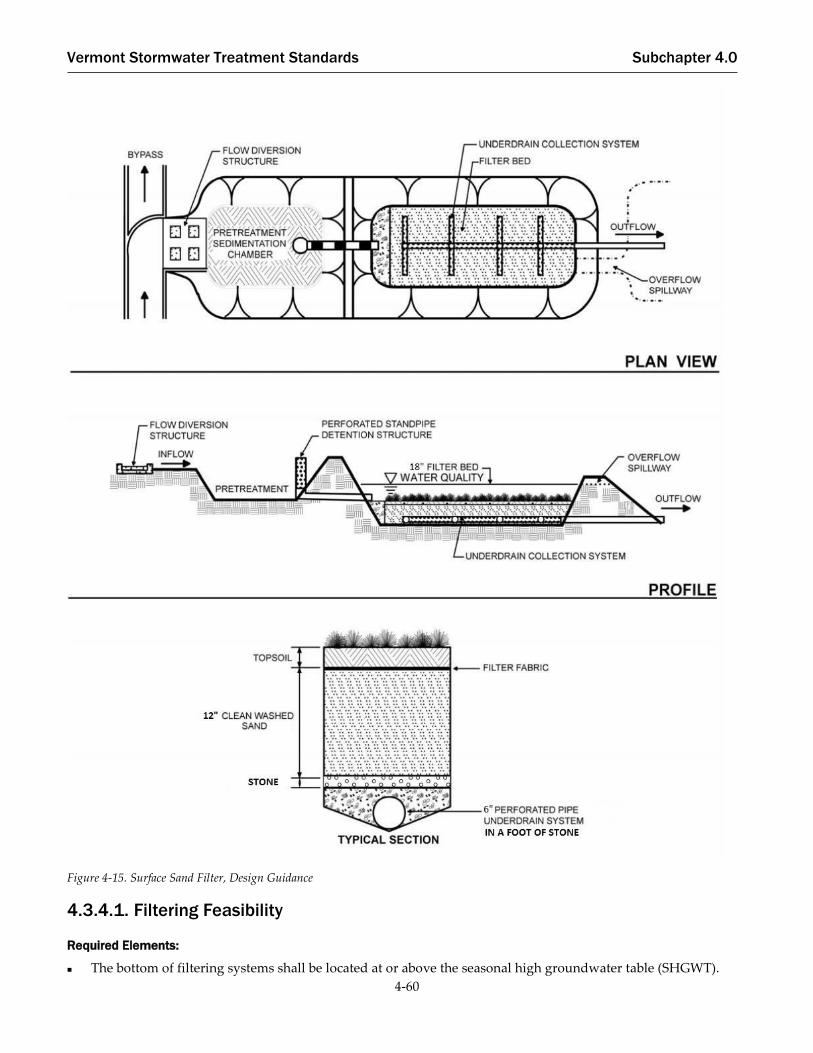
Vermont Stormwater Treatment Standards Subchapter 4.0
4-60
Figure 4-15. Surface Sand Filter, Design Guidance
4.3.4.1. Filtering Feasibility
Required Elements:
The bottom of filtering systems shall be located at or above the seasonal high groundwater table (SHGWT).

Vermont Stormwater Treatment Standards Subchapter 4.0
4-61
If the filtering practice is designed to infiltrate stormwater through the bottom of the practice into underlying
soils, the soils shall have an infiltration rate (fc) of at least 0.2 inches per hour, as confirmed by soil testing
requirements for infiltration pursuant to Section 4.3.3.2.
For filtering practices designed to infiltrate stormwater, applicable feasibility required elements for infiltration
trench and basin practices shall also be met (Section 4.3.3.1). The separation to SHGWT requirements identified
in Section 4.3.3.1 are not applicable to filtering practices designed to treat the water quality and groundwater
recharge volumes only.
Systems designed to infiltrate more than the WQV shall maintain a minimum 3-foot separation to SHGWT from
the bottom of the practice; unless contributing drainage area to the practice is less than or equal to 1 acre, then
there shall be a:
o Minimum of 2 feet separation to SHGWT from the bottom of the filtering system when the
contributing drainage area (CDA) of 1 acre or less is greater than 50% impervious.
o Minimum of 1 foot separation to SHGWT from the bottom of the filtering system when the
contributing drainage area (CDA) of 1 acre or less is less than or equal to 50% impervious.
Design Guidance:
Most stormwater filters require four to six feet of head, depending on site configuration and land area
available. The perimeter sand filter, however, can be designed to function with as little as 18 to 24 inches of
head.
Sand filtering systems are generally applied to land uses with a high percentage of impervious surfaces. Sites
with contributing area imperviousness greater than 75%, and sites with high sediment loading (such as
aggressive use of traction sand for de-icing), may require more aggressive sedimentation pre-treatment
techniques.
4.3.4.2. Filtering Conveyance
Required Elements:
If runoff is delivered by a storm drain pipe or is along the main conveyance system, the filter practice shall be
designed off-line. In these cases, a flow regulator or flow splitter diversion structure shall be supplied to divert
the WQV to the filter practice, and allow larger flows to bypass the practice.
In cases where filtering practices are designed as on-line practices, an overflow shall be provided within the
practice to pass flows in excess of the WQV or TV to a stable conveyance. Designers shall indicate how on-line
filtering practices will safely pass the 10-year storm without re-suspending or flushing previously trapped
material.
To prevent erosion, an overflow for the 10-year storm shall be provided to a non-erosive outlet point.
Stormwater from filtering system outlets shall be conveyed to discharge location in non-erosive manner.
Underdrained stormwater filters shall be equipped with a minimum 6-inch perforated pipe underdrain (8-inch
is preferred) in a minimum 1-foot stone layer. Within the stone layer the underdrain pipe shall be separated by
at least 3 inches from the filter media and 2 inches from the bottom of the practice. Synthetic filter fabrics shall
not be used to completely separate the filter media from the underdrain bedding material.
Filtering systems shall not be lined unless required due to hotspot land use or other site specific factors, subject
to Agency approval.

Vermont Stormwater Treatment Standards Subchapter 4.0
4-62
Design Guidance:
When designing the flow splitter, the designer should exercise caution to ensure that 75% of the WQV can enter
the treatment system prior to flow bypass occurring at the flow splitter. The overflow weir between the
sedimentation and filtration chambers may be adjusted to be lower in elevation than the flow splitter weir to
minimize bypass of the filter system prior to inflow filling the 75% WQV storage.
Filtering practices should be designed to completely drain or dewater within 48 hours (2 days) after a storm
event to reduce the potential for nuisance ponding conditions.
4.3.4.3. Filtering Pre-Treatment
Pre-treatment of roof runoff is not required, provided the runoff is routed to the filtering practice in a manner such
that it is unlikely to accumulate significant additional sediment, for example via a closed pipe system or grass
channel, and provided the runoff is not commingled with other runoff.
Required Elements:
If stormwater is routed to a forebay for required pre-treatment, the forebay shall be volumetrically sized for
25% of the computed WQV. Otherwise, required pre-treatment shall be designed in accordance with Section
4.1.
Design Guidance:
Pre-treatment devices, including sediment forebays may be designed as level spreaders such that inflows to the
filter bed have near zero velocity and spread runoff evenly across the surface.
4.3.4.4. Filtering Treatment
Required Elements:
A storage volume of at least 75% of the design TV, including the volume over the top of the filter media and the
volume in the sediment forebay as well as within the filter media – is required to capture the volume from
high-intensity storms prior to filtration and to avoid premature bypass.
Filter media shall consist of a medium sand (ASTM C- 33 concrete sand) or approved equivalent.
The filter bed shall have a minimum depth of 18 inches. The perimeter filter shall have a minimum filter bed
depth of 12 inches.
The filter area for sand filters shall be sized based on the principles of Darcy’s Law. A coefficient of
permeability (k) shall be used as follows:
Sand: 3.5 ft/day
(Note: the above value is conservative to account for clogging associated with accumulated sediment)
The filter bed area shall be computed using the following equation:
Af =(Tv)(df)
(k)(hf + df)(tf)
Where:
Af = Surface area of filter bed (ft2)
TV = Treatment volume (ft3)
df = Filter bed depth (ft)
k = Coefficient of permeability of filter media (ft/day)
Equation 4-7

Vermont Stormwater Treatment Standards Subchapter 4.0
4-63
hf = Average height of water above filter bed (ft)
tf = Design filter bed drain time (days)
(2 days is the recommended maximum tf for sand filters)
Design Guidance:
The depth of the filter media plays a role in how quickly stormwater moves through the filter bed and how
well it removes pollutants. A minimum filter bed depth of 12 to 18 inches is recommended for most
applications. Greater filter media depths can be used in order to facilitate the removal of 1 to 3 inches of sand
during maintenance without having to replace sand every time the top few inches of sand is removed.
The surface slope of filters should be level to promote even distribution of flow throughout the practice.
Filter beds should be extended below the frost line to prevent the filtering medium from freezing during the
winter.
Filtering systems may be combined with another stormwater treatment practice that can be used as a backup to
the filtering system to provide treatment during the winter when the filter bed may be frozen.

Vermont Stormwater Treatment Standards Subchapter 4.0
4-64
Figure 4-16. Underground Sand Filter, Design Guidance
4.3.4.5. Filtering Vegetation and Landscaping
Required Elements:
The entire contributing area shall be stabilized before runoff can be directed into a filtration practice. A dense
and vigorous vegetative cover shall be established over the contributing pervious drainage areas, and
impervious area construction must be completed.

Vermont Stormwater Treatment Standards Subchapter 4.0
4-65
Design Guidance:
Surface filters can have a grass cover to aid in pollutant adsorption. The grass should be capable of
withstanding frequent periods of inundation and drought.
Figure 4-17. Perimeter Sand Filter, Design Guidance

Vermont Stormwater Treatment Standards Subchapter 4.0
4-66
Treatment Standard Applicability:
Groundwater
Recharge
Yes. (if designed for infiltration)
Water Quality Yes. Tier 1 Practice (designed for infiltration) / Tier 3 Practice (underdrained and/or
lined)
Channel Protection Limited. Hydrologic Condition Method (if designed for infiltration)/ Extended
Detention Method (underdrained and/or lined)
Overbank Flood
Protection (QP10) and
Extreme Flood
Protection (QP100)
Limited. CNAdj may provide partial credit for volume infiltrated (Tv)
Key Elements:
Feasibility:
▪ Infiltration rate shall be ≥0.2 inches per hour as confirmed by methods in Section 4.3.3.2 if designed
to infiltrate.
▪ SHGWT must be below bottom of the practice for Water Quality Treatment Standard. Separation to
SHGWT for larger storm events varies based size of practice and volume designed to infiltrate.
Pre-treatment:
▪ Forebay sized for 25% of the WQV or other pre-treatment as described in Section 4.1
Treatment:
▪ Filter media is ≥18 inches of medium sand for filter beds. Perimeter filters shall have ≥ 12 inches of
sand.
▪ Filter bed is designed according to Darcy’s Law. Storage volume (including pre-treatment) shall be at
least 75% of TV.
▪ TV is credited towards WQV. For infiltrating practices, this same treatment volume is applied to ReV,
CPV, QP10, and QP100. For underdrained practices, HCV is limited to pore space below underdrain.
▪ Maximum dewatering time of 48 hours.
Other:
▪ Minimum 6-inch diameter perforated pipe underdrain shall be provided if not designed to infiltrate.
Information contained in this table is for quick reference and is not inclusive of all requirements. All required
elements in this section shall be met in order for the STP to be in conformance with this Manual.

Vermont Stormwater Treatment Standards Subchapter 4.0
4-67
Treatment Wetlands
Constructed treatment wetlands are stormwater wetland systems that maximize pollutant removal and the uptake
of nutrients through wetland vegetation, retention, and settling. The two primary categories of constructed
wetlands that are recommended for stormwater treatment include shallow surface wetlands and gravel wetlands.
Shallow surface wetlands use organic wetland soils at the surface and have a permanent pool of water with
varying pool depths that supports the growth of wetland plants. The pools in shallow surface systems are
designed with zones that have varying depth ranges:
Deep water – greater than 18-inch depth, up to the maximum design depth of typically 4 to 6 feet;
Low marsh – 6-inch to 18-inch depth below normal pool;
High marsh – Up to 6-inch depth below normal pool; and
Semi-wet – Areas above normal pool that are periodically inundated and expected to support wetland
vegetation.

Vermont Stormwater Treatment Standards Subchapter 4.0
4-68
Figure 4-18. Shallow Surface Wetland, Design Guidance

Vermont Stormwater Treatment Standards Subchapter 4.0
4-69
In contrast to the shallow surface wetlands, gravel wetlands store water within the interstitial void spaces of the
gravel. Gravel systems typically have a 24-inch to 36-inch deep gravel bed that is saturated to the surface or just
below the surface.
Figure 4-19. Gravel Wetland, Design Guidance

Vermont Stormwater Treatment Standards Subchapter 4.0
4-70
4.3.5.1. Treatment Wetland Feasibility
Required Elements:
Shallow surface treatment wetlands discharging directly to cold-water fishery streams shall be designed to
discharge up to and including the CPV through an underdrained stone trench outlet. Gravel wetlands are not
subject to the stone trench outlet requirement. Additional storage for QP10 and QP100 may be discharged through
traditional outlet structures.
Design Guidance:
A site evaluation by the designer may be necessary to establish the Hazard Classification of any embankment.
It is the designer’s responsibility to determine the design elements required to ensure dam safety and to
incorporate those elements into the treatment wetland design. Designers may choose to consider alternative
placement and/or design refinements to reduce or eliminate the potential for designation as a significant or
high hazard dam.
4.3.5.2. Treatment Wetland Conveyance
Required Elements:
Flow paths from the inflow points to the outflow points of shallow treatment wetlands shall be maximized
through the use of internal design geometry and the inclusion of features such as berms, baffles, and islands in
design plans. The minimum length to width ratio for a shallow treatment wetland is 2:1.
Inlet areas shall be stabilized to ensure that non-erosive conditions exist for at least the 1-year design storm
event.
A low-flow orifice shall be provided if the pond is designed to meet the extended detention requirements of the
WQV and CPV. The orifice shall be sized to provide the required detention time during the applicable design
storm(s) and designed to ensure that no clogging shall occur.
When a treatment wetland is located in medium to coarse sands and above the average groundwater table, a
liner shall be used to sustain a permanent pool of water. If geotechnical tests confirm soils with an infiltration
rate of 0.05 inches per hour or greater, then a liner is required. The acceptable liner options include: (a) 6 to 12
inches of clay soil (minimum 15% passing the #200 sieve and a maximum permeability of 1 x 10⁻⁵ cm/sec), (b) a
30 mil poly-liner, or (c) bentonite. The channel immediately below a treatment wetland outfall shall be
modified to prevent erosion and conform to natural dimensions in the shortest possible distance, typically by
use of appropriately sized riprap placed over filter fabric. A stilling basin or outlet protection shall be used to
reduce flow velocities from the principal spillway to non-erosive velocities of 3.5 to 5.0 fps. Stormwater from
treatment wetland outlets shall be conveyed to discharge location in non-erosive manner.
Shallow Surface Treatment Wetlands
o For shallow surface wetlands, inlet pipes shall be set at the permanent pool or slightly above to
limit erosive conditions.
o Shallow surface wetlands draining to cold-water fisheries shall be designed to discharge volumes
up to and including the CPV through an underdrained stone trench and shall be designed to meet
the following requirements:
▪ The trench shall be at least 4 feet wide, located at least 2 feet from the permanent pool, and
located at the furthest location opposite from the principal inflow location to the practice;
Vermont Stormwater Treatment Standards Subchapter 4.0
4-71
▪ The bench shall be set at the permanent pool elevation such that the CPV will be stored
between the bench surface elevation and the elevation of any flood control or emergency
spillway;
▪ The trench shall have a length of 3 feet per 1,000 cubic feet of extended detention storage
volume, have a depth of at least 3 feet, and maintain 2 feet of stone cover over a 6-inch
diameter perforated pipe outlet;
▪ Geotextile fabric shall be placed between the stone trench and adjacent soil; and
▪ Uniformly-sized stone shall be used.
▪ The pond outlet or orifice shall be designed to prevent clogging and to allow access to the
underdrain outlet for inspection and maintenance.
▪ The underdrain outlet shall be sized and modelled to provide the required extended
detention of the WQV and CPV.
Gravel Wetlands
o For gravel wetlands, inlet pipes shall be set either at the permanent pool or at the base of the gravel
bed.
o Gravel wetlands designed with an organic soil layer at the surface shall have vertical perforated
riser pipes or other conveyance means that deliver stormwater from the surface down to the
subsurface perforated distribution lines. The vertical risers shall not be capped, but rather covered
with an inlet grate to allow for overflow when the water level exceeds the WQV.
o A sub-surface water level shall be maintained in the gravel wetland through the design of the
outlet elevation.
Design Guidance:
Outfalls should be constructed such that they do not increase erosion or have undue influence on the
downstream geomorphology of any natural watercourse by discharging at or near the stream water surface
elevation or into an energy dissipating step-pool arrangement.
The treatment wetland outlet structure should be based on a calculated release rate by orifice control to drain
the WQV over 24 hours, when extended detention (ED) is a component of the design. The practice may also
have an additional orifice for draining the CPV as required by the Channel Protection Standard.
4.3.5.3. Treatment Wetland Pre-Treatment
Required Elements:
If a forebay is utilized for pre-treatment, the forebay shall be volumetrically sized to contain a minimum of 10%
of the computed WQV. Otherwise, required pre-treatment shall be designed in accordance with Section 4.1.
Forebay storage volume shall count toward the total WQV requirement.
Exit velocities from pretreatment chambers flowing over vegetated channels shall be non-erosive, in other
words 3.5 to 5.0 fps, during the 1-year design storm.
Design Guidance:
The bottom of the forebay may be hardened (i.e., concrete, asphalt, grouted riprap) to make sediment removal
easier.

Vermont Stormwater Treatment Standards Subchapter 4.0
4-72
4.3.5.4. Treatment Wetland Treatment
Required Elements:
Shallow surface treatment wetlands.
o A minimum of 35% of the total surface area in the permanent pool shall have a depth of 6 inches or
less, and at least 65% of the total permanent pool surface area shall be shallower than 18 inches.
o At least 10% of the WQV shall be provided in a sediment forebay if used for pre-treatment. At least
25% of the WQV shall be provided in “deep water zones” with a depth equal to or greater than 4
feet. The remaining WQV shall be provided through a combination of shallow permanent pool
with depth less than 4 feet and the extended detention (ED) storage volume above the permanent
pool, as applicable. ED storage volume shall not exceed 50% of the WQV and shall drain over 24
hours.
o Shallow surface treatment wetlands shall have a length to width ratio of 2:1 (L:W).
Gravel wetlands.
o At least 10% of the WQV shall be provided in a sediment forebay if used for pre-treatment. The
remaining WQV shall be provided through a combination of one or more basins or chambers filled
with a minimum 24-inch gravel layer and the open, ED storage volume above the gravel, as
applicable. ED storage volume shall not exceed 50% of the WQV and shall drain over 24 hours.
o Gravel wetlands shall have a length to width ratio of 1:1 (L:W) or greater as needed for each
treatment cell, with a minimum flow path (L) within the gravel substrate of 15 feet.
Shallow surface wetlands and gravel wetlands do not achieve runoff reduction and therefore do not receive a
treatment volume credit toward the Groundwater Recharge Standard or the Hydrologic Condition Method of
the Channel Protection Standard. The practice may be used to meet the Water Quality Treatment Standard, the
Overbank Flood Control Standard, and the Extreme Flood Control Standard.
Design Guidance:
Water quality storage can be provided in multiple cells. Performance is enhanced when multiple treatment
pathways are provided by using multiple cells, longer flow paths, high surface area to volume ratios, complex
microtopography (complex contours along the bottom of the shallow treatment wetland, providing greater
depth variation), and/or redundant treatment methods (combinations of pool, ED, and emergent vegetation).
Basins shall follow natural landforms to the greatest extent possible or be shaped to mimic a naturally formed
depression.
For gravel wetlands, a layer of organic soil may be used as substrate for emergent vegetation, but is not
necessary depending on chosen species. If an organic soil layer is used as a top layer, it should have a
minimum thickness of 8 inches, should be leveled (constructed with a surface slope of zero), and should be
underlain by 3 inch minimum thickness of an intermediate layer of a graded aggregate filter to prevent the
organic soil from moving down into the gravel sublayer.
4.3.5.5. Treatment Wetland Landscaping and Vegetation
Required Elements:
The perimeter of all deep pool areas four feet or greater in depth shall be surrounded by two benches as
follows:

Vermont Stormwater Treatment Standards Subchapter 4.0
4-73
o Except when side slopes are 4:1 (H:V) or flatter, a safety bench shall be provided that extends 10
feet outward from the normal water edge to the toe of the treatment wetland side slope. The
maximum slope of the safety bench shall be 6%; and
o An aquatic bench shall be incorporated that extends at least 5 feet inward from the normal edge of
water and has a maximum depth of 18 inches below the normal pool water surface elevation.
A planting plan for a treatment wetland and surrounding areas shall be prepared to indicate how aquatic and
terrestrial areas will be stabilized and established with vegetation. Minimum elements of a plan include:
delineation of pondscaping zones, selection of corresponding plant species, plant locations, sequence for
preparing treatment wetland bed (including soil amendments, if needed), and sources of plant material.
Donor organic soils for treatment wetlands shall not be removed from natural wetlands.
A setback from the treatment wetland shall be provided that extends 25 feet outward from the maximum
design water surface elevation of the practice.
Woody vegetation shall not be planted or allowed to grow on a dam, or within 15 feet of a dam or toe of the
embankment, or within 25 feet of a principal spillway outlet.
Design Guidance:
The best elevations for establishing emergent plants, either through transplantation or volunteer colonization,
are within six inches (plus or minus) of the normal pool.
The soils surrounding a treatment wetland are often severely compacted during the construction process to
ensure stability. The density of these compacted soils is often so great that it effectively prevents root
penetration, and therefore, may lead to premature mortality or loss of vigor. Consequently, it is advisable to
excavate large and deep holes around the proposed planting sites, and backfill these with uncompacted topsoil.
A gravel wetland should be planted to achieve a rigorous root mat with grasses, forbs, and shrubs, using
obligate and facultative-wetland plant species.
Planting holes should be the same depth as the root ball and two to three times wider than the diameter of the
root ball. In addition, the root ball of container-grown stock should be gently loosened or scored along the
outside layer of roots to stimulate new root development. This practice should enable the stock to develop
unconfined root systems. Avoid species that require full shade or are prone to wind damage. Proper mulching
around the base of trees and shrubs (2-4 inches of mulch, kept 1-2 inches away from trunks or stems) is
strongly recommended as a means of conserving moisture and suppressing weed growth.
Structures such as fascines, coconut rolls, or carefully designed stone weirs can be used to create shallow cells
in high-energy flow areas of the shallow treatment wetland.
Existing trees should be preserved around the treatment wetland area during construction. It is also desirable
to locate forest conservation or reforestation areas adjacent to treatment wetlands. To help encourage
reforestation and discourage resident geese populations, the area immediately surrounding the permanent
pool can be planted with trees, shrubs and native ground covers.

Vermont Stormwater Treatment Standards Subchapter 4.0
4-74
Treatment Standard Applicability:
Groundwater
Recharge
No
Water Quality Yes. Gravel Wetland - Tier 2 Practice, Shallow Surface Wetland - Tier 3 Practice
Channel Protection Yes. Extended Detention Method
Overbank Flood
Protection (QP10) and
Extreme Flood
Protection (QP100)
Yes
Key Elements:
Pre-treatment:
▪ Forebay sized for 10% of the WQV or other pre-treatment as described in Section 4.1.
Treatment:
▪ Shallow Surface Wetlands
o Minimum 35% of the WQV storage shall be at design depth of less than 6 inches. A
minimum of 65% of the WQV storage shall be at design depth of less than 18 inches.
o At least 25% of the WQV storage shall be provided in deep water zones at design depths
greater than 4 feet.
o Minimum length to width ratio of 2:1.
▪ Gravel Wetlands
o WQV is stored in a combination of gravel storage and extended detention. Extended storage
shall not exceed 50% of the WQV.
o Minimum length to width ration of 1:1. Minimum flow path within the gravel substrate is 15
feet.
Other:
▪ Shallow surface wetlands discharging to cold water fisheries shall be designed to discharge storms
up to and including the 1-year, 24-hour storm event (CPV) through a gravel trench outlet.
▪ A liner is required if underlying soils have an infiltration rate >0.05 inches per hour.
▪ 10-foot safety bench around deep pool areas (4 feet or deeper) extending outward from normal
water surface, unless side slopes are 4:1 or shallower.
▪ 5-foot aquatic bench required extending ≥5 feet inward from normal water surface.

Vermont Stormwater Treatment Standards Subchapter 4.0
4-75
Wet Ponds
Wet ponds consist of a permanent pool of standing water that promotes a stable environment for gravitational
settling, biological uptake, and microbial activity. Runoff from each new storm enters the pond and partially
displaces pool water from previous storms. The pool also acts as a barrier to re-suspension of sediments and other
pollutants deposited during prior storms. When sized properly, wet ponds have a residence time that ranges from
many days to several weeks, which allows numerous pollutant removal mechanisms to operate. Wet ponds can
also provide extended detention (ED) above the permanent pool to help meet CPV, QP10, and QP100 requirements.
Figure 4-20. Wet Pond, Design Guidance

Vermont Stormwater Treatment Standards Subchapter 4.0
4-76
4.3.6.1. Wet Pond Feasibility
Required Elements:
Ponds receiving runoff from stormwater hotspots shall be lined and shall not intercept ground water.
Ponds shall not include the volume of the permanent pool in storage calculations for storms greater than the
water quality event.
Design Guidance:
A site evaluation by the designer may be necessary to establish the Hazard Classification. It is the designer’s
responsibility to determine the design elements required to ensure dam safety and to incorporate those
elements into the pond design. Designers may choose to consider alternative placement and/or design
refinements to reduce or eliminate the potential for designation as a significant or high hazard dam.
Slopes immediately adjacent to ponds should be less than 25% but greater than 1% to promote flow toward the
pond.
The use of wet ponds is highly constrained at development sites with steep terrain. Some adjustments can be
made by terracing pond cells in a linear manner, using 1 to 2 foot armored elevation drop between individual
cells. Terracing may work well on longitudinal slopes with gradients up to approximately 10%.
The depth of a wet pond should be determined by the hydraulic head available on the site. The bottom
elevation is normally the invert of the existing downstream conveyance system to which the wet pond
discharges. Typically, a minimum of 6 to 8 feet of head are needed for a wet pond to function.
Highly permeable soils make it difficult to maintain a constant level for the permanent pool. Underlying soils
of Hydrologic Soil Group (HSG) C or D should be adequate to maintain a permanent pool. HSG A soils and
some HSG B soils may require a liner. Geotechnical tests should be conducted to determine the infiltration
rates and other subsurface properties of the soils beneath the proposed pond to determine liner applicability. If
geotechnical tests confirm that a liner is needed to sustain a permanent pool, some options include: (a) 6 to 12
inches of clay soil (minimum 15% passing the #200 sieve and a maximum permeability of 1 x 10⁻⁵ cm/sec), (b) a
30 mil poly-liner (c) bentonite.
For situations with shallow bedrock and groundwater, pond use is limited due to the available depth, which
will affect the surface area required as well as the aesthetics of the pond. Consider stormwater treatment
wetlands as an alternative.
4.3.6.2. Wet Pond Conveyance
Required Elements:
Inlet areas shall be stabilized to ensure that non-erosive conditions exist during events up to the Q10 event.
A low-flow orifice shall be provided if the pond is designed to meet the extended detention requirements of the
WQV and CPV. The orifice shall be sized to provide the required detention time during the applicable design
storm(s) and designed to ensure that no clogging shall occur.
Wet ponds in watersheds draining to cold water fisheries shall be designed to discharge volumes up to and
including the CPV through an under-drained stone trench outlet that meets the following requirements:
o The trench shall be excavated in a pond bench having a minimum width of 8 feet. The trench shall
be 4 feet wide, located at least 2 feet laterally from the permanent pool on the pond side of the

Vermont Stormwater Treatment Standards Subchapter 4.0
4-77
bench, and located at the furthest location opposite from the principal inflow location to the
practice;
o The bench shall be set at the permanent pool elevation such that the CPV will be stored between the
bench surface elevation and the elevation of any flood control or emergency spillway;
o The trench shall have a length of 3 feet per 1,000 cubic feet of extended detention storage volume,
have a depth of at least 3 feet, and maintain 2 feet of stone cover over and 6 inches below a 6-inch
diameter perforated pipe outlet;
o Geotextile fabric shall be placed between the sides of the stone trench and adjacent soil;
o Uniformly-sized stone shall be used;
o The pond outlet or orifice shall be designed to prevent clogging and to allow access to the
underdrain outlet for inspection and maintenance; and
o The underdrain outlet shall be sized and modeled to provide the required extended detention of
the WQV and CPV.
Additional storage for QP10 and QP100 may be discharged through traditional basin outlet structures.
The design shall specify an outfall that will be stable for the Q10 design storm event.
The channel immediately below a wet pond outfall shall be modified to prevent erosion and conform to natural
dimensions in the shortest possible distance, typically by use of appropriately sized riprap placed over filter
fabric, stilling basin or outlet protection shall be used to reduce flow velocities from the principal spillway to
non-erosive velocities of 3.5 to 5.0 fps.
Stormwater from wet pond outlets shall be conveyed to discharge location in non-erosive manner.
The outlet control structure shall be located within the embankment for maintenance access and safety.
All basins shall have an emergency spillway, maintaining at least 1 foot of freeboard between the peak storage
elevation and the top of the embankment crest, and to safely convey the 100-year storm without overtopping
the embankment.
Emergency spillways are required for the 100-year storm event.
End walls above pipe outfalls greater than 30 inches in diameter shall be fenced with pipe or rebar at 8-inch
intervals to prevent a hazard.
If pond draining is required for any reason, the pond shall be drained in a non-erosive fashion and with
consideration of impacts to downstream properties.
Design Guidance:
Inlet pipe inverts should generally be located at or slightly below the permanent pool surface. If the inlet is
partially submerged it can limit erosive conditions. In no case should it be submerged more than one half of the
pipe diameter.
Inlet pipes should have a slope of no less than 1% to prevent standing water in the pipe and reduce the
potential for ice formation.
The low-flow orifice should be adequately protected from clogging by either an acceptable external trash rack
(recommended minimum orifice of 3 inches) or by internal orifice protection that may allow for smaller
diameters (recommended minimum orifice of 1 inch).

Vermont Stormwater Treatment Standards Subchapter 4.0
4-78
o The preferred method is a submerged reverse-slope pipe that extends downward from the outlet
control structure to an inflow point one foot below the normal pool elevation
o Alternative methods are to employ a broad-crested rectangular, V-notch, or proportional weir,
protected by a half-round pipe or “hood” that extends at least 12 inches below the normal pool.
o Vertical pipes may be used as an alternative where a permanent pool of sufficient depth is present.
Outfalls should be constructed such that they do not increase erosion or have an undue influence on the
downstream geomorphology of any natural watercourse by discharging at or near the stream water surface
elevation or into an energy dissipating step-pool arrangement.
Access to an outlet control structure should be provided by a lockable manhole cover and manhole steps
within easy reach of valves and other controls.
Figure 4-21. Gravel Outlet Trench, Design Guidance

Vermont Stormwater Treatment Standards Subchapter 4.0
4-79
4.3.6.3. Wet Pond Pre-Treatment
Required Elements:
Each wet pond shall have a sediment forebay sized to contain at least 10% of the WQV. Otherwise, pre-
treatment shall be provided sized in accordance with Section 4.1.
Design Guidance:
The volume contained within the sediment forebay counts toward the total WQv requirement.
If winter traction sanding is prevalent in the contributing drainage area, the forebay size may be increased to
25% of the WQV to accommodate additional sediment loading.
The bottom of the forebay may be hardened (i.e., concrete, asphalt, grouted riprap) to make sediment removal
easier.
4.3.6.4. Wet Pond Treatment
Required Elements:
At least 25% of the WQV shall be provided in “deep water zones” with a depth equal to or greater than 4 feet,
but not more than 8 feet. As required above, at least 10% of the WQV shall be provided in a sediment forebay
or other pretreatment practice. The remaining 65% of the WQV shall be provided in some combination of
shallow permanent pool with depth less than four feet and the extended detention (ED) storage volume above
the permanent pool, as applicable. ED storage volume shall not exceed 50% of the WQV.
Flow paths at the normal water level from the inflow points to the outflow points shall be maximized through
the use of geometry and features such as internal berms, baffles, vegetated peninsulas, or islands. The
minimum flow path length to practice width ratio is 3:1.
The ratio of the shortest flow path (distance from the closest inlet to the outlet) to the overall length (distance
from the farthest inlet to the outlet) must be at least 0.8. In some cases, due to site geometry, storm sewer
infrastructure, or other factors, some inlets may not be able to meet these ratios; the drainage area served by
these “closer” inlets shall not constitute more than 20% of the total contributing drainage area. The Agency
may require additional pre-treatment for closer inlets.
Design Guidance:
Water quality storage can be provided in multiple cells. Performance may be enhanced when multiple
treatment pathways are provided using multiple cells, long flow paths, high surface area to volume ratios,
complex microtopography (e.g., complex contours along the bottom of the pond, providing greater depth
variation) and/or redundant treatment methods (e.g., combinations of pool, extended detention, and emergent
vegetation). A berm or simple weir should be used instead of pipes to separate multiple pond cells.
The bed of the wet pond should be graded to create maximum internal flow path and microtopography.
Microtopography is encouraged to enhance plant diversity.
Credit towards the WQV is based on the volume of water contained within the permanent pool, including
forebay, and any additional volume designed for extended detention (ED) of 24-hours.
Wet Pond Vegetation and Landscaping
Required Elements:
The perimeter of all deep pool areas of 4 feet or greater in depth shall be surrounded by 2 benches as follows:

Vermont Stormwater Treatment Standards Subchapter 4.0
4-80
o Except when side slopes are 4:1 (H:V) or flatter, a safety bench shall be provided that generally
extends 10 feet outward from the normal water edge to the toe of the side slope. The maximum
slope of the safety bench shall be 6%; and
o An aquatic bench shall be incorporated that extends at least 5 feet inward from the normal edge of
water and has a maximum depth of 18 inches below the normal pool water surface elevation.
A planting plan for the wet pond shall be prepared to indicate how aquatic and terrestrial areas will be
stabilized, as well as how vegetated cover will be established and maintained. Minimum elements of a plan
shall include: delineation of pondscaping zones; selection of corresponding plant species; plant locations;
sequence for preparing planting areas, including soil amendments, if needed; and sources of plant material.
Woody vegetation that is more than 2 inches in diameter shall not be planted or allowed to grow on a dam or
within 15 feet of a dam or the toe of the embankment.
Design Guidance:
For benching considerations above, the referred to “side slopes” are those areas around the pond that lead
down to the permanent pool surface, or normal water’s edge.
Existing trees should be preserved in the setback area during construction. It is desirable to locate reforestation
areas adjacent to wet ponds, which can help discourage populations of resident geese.
The best elevations for establishing emergent plants, either through transplantation or volunteer colonization,
are within six inches (plus or minus) of the normal pool.
The soils of the setback are often severely compacted during the construction process to ensure stability. The
density of these compacted soils is so great that it effectively prevents root penetration, and therefore, may lead
to premature mortality or loss of vigor. Consequently, it is advisable to excavate large and deep holes around
the proposed planting sites, and backfill these with uncompacted topsoil. Additional information on best
practice for tree planting, including planting specifications, are provided in Reforestation (Section 4.2.1).
Planting holes should be the same depth as the root ball and two to three times wider than the diameter of the
root ball. In addition, the root ball of container-grown stock should be gently loosened or scored along the
outside layer or roots to stimulate new root development. This practice should enable the stock to develop
unconfined root systems. Avoid species that require full shade or are prone to wind damage. Extra mulching
around the base of the tree or shrub is strongly recommended as a means of conserving moisture and
suppressing weeds.
Species that require full shade, are susceptible to winterkill, or are prone to wind damage should be avoided.
Both the safety bench and the aquatic bench should be landscaped to discourage resident geese populations on
the permanent pool.
Pond fencing may be required in some situations or by some municipalities. A preferred method is to manage
the contours of the pond to eliminate drop-offs or other safety concerns.
Warning signs prohibiting swimming, skating, or access, may be posted.

Vermont Stormwater Treatment Standards Subchapter 4.0
4-81
Treatment Standard Applicability:
Groundwater
Recharge
No
Water Quality Yes. Tier 3 Practice
Channel Protection Yes. Extended Detention Method
Overbank Flood
Protection (QP10) and
Extreme Flood
Protection (QP100)
Yes
Key Elements:
Pre-treatment:
▪ Forebay sized for 10% of the WQV or other pre-treatment as described in Section 4.1.
Treatment:
▪ At least 25% of the WQV shall be in deep water zones.
▪ Extended detention (ED) storage shall not exceed 50% of the WQV.
▪ Minimum length to width ration of 3:1.
Other:
▪ Wet ponds discharging to cold water fisheries shall be designed to discharge storms up to and
including the 1-year, 24-hour storm event (CPV) through a gravel trench outlet.
▪ 10-foot safety bench around deep pool areas (4 feet or deeper) extending outward from normal
water surface, unless side slopes are 4:1 or shallower.
▪ 5-foot aquatic bench required extending ≥5 feet inward from normal water surface.
Information contained in this table is for quick reference and is not inclusive of all requirements. All required
elements in this section shall be met in order for the STP to be in conformance with this Manual.

Vermont Stormwater Treatment Standards Subchapter 4.0
4-82
Green Roofs
There are two common approaches for using alternative stormwater management treatments for the rainfall that
falls on building rooftops. “Green roofs” are rooftop areas that are partially or completely landscaped with
vegetation. The other approach involves strictly rooftop detention and is commonly referred to as a “blue roof.”
Blue roofs have been applied in combined sewer overflow (CSO) areas to help attenuate rooftop flows to reduce
CSOs, and would be potentially applicable in places such as the City of Burlington. But since they provide only
storage and detention capabilities, and do not offer widespread application in Vermont, they are not examined
further in this Manual as an applicable green stormwater infrastructure practice. They still, however, may be
proposed for storage as part of an overall stormwater management plan.
A typical green roof includes vegetation planted in a substrate over a drainage layer and a root barrier membrane.
There are two main types: (1) intensive, which are planted with woody vegetation with a deeper planting soil and
walkways, and (2) extensive, which are vegetated with short, drought-tolerant species, such as sedums, and a
shallow growing media. Some green roofs are constructed with stormwater detention tanks and a pump back
system to recirculate water during dry periods and allow for additional uptake of first flush pollutants. Green
roofs provide several benefits, including reduction of stormwater runoff through absorption, storage, and
evapotranspiration. Ancillary benefits include reduction of urban heat island effects and increased building energy
efficiency; and increased roof durability and lifespan.
Figure 4-22. Example of Extensive Green Roof, Philadelphia, PA, Design Guidance (Source: UNHSC)
4.3.7.1. Green Roof Feasibility
Required Elements:
The system shall have a maximum slope of 20%, unless specific measures from the manufacturer are provided
to retain the system on steeper slopes.
Green roofs shall only be used to manage precipitation that falls directly on the rooftop area.

Vermont Stormwater Treatment Standards Subchapter 4.0
4-83
Design Guidance:
Extensive rooftops are commonly designed for maximum thermal and hydrological performance and
minimum weight load while being aesthetically pleasing. Typically, only maintenance personnel have access to
this type of roof. Extensive practices can be installed on either a flat or pitched roof.
Intensive rooftops are designed with a deeper planting media, larger plants (trees and shrubs), and often
incorporate public walkways and benches. These are installed on flat roofs.
4.3.7.2. Green Roof Conveyance
Required Elements:
Roof drain designs shall include at least 2 outlets or an outlet and an overflow. Outlets shall be kept clear of
vegetation by installing a vegetation free zone around the outlet or overflow.
The runoff exceeding the capacity of the green roof system shall be safely conveyed to a drainage system or
another STP without causing erosion. If an overland path is used, a stabilized channel shall be provided for
erosive velocities of 3.5 to 5.0 ft/s for the 1-year storm event.
The green roof system shall safely convey runoff from the 100-year storm away from the building and into a
downstream drainage system.
Design Guidance:
Designers may incorporate a variety of measures to ensure waterproof conditions between the growing
medium and the rooftop.
Figure 4-23. Extensive Green Roof (L) & Intensive Green Roof (R), Design Guidance (Source: Wark and Wark 2003)

Vermont Stormwater Treatment Standards Subchapter 4.0
4-84
4.3.7.3. Green Roof Treatment
Required Elements:
Green roofs shall receive TV credit equal to the volume of runoff stored in the void space of the planting
medium above the drain layer and without bypass to the overflow system. The treatment volume shall be
calculated as follows:
Tv = Ag×n×dt
where:
TV = treatment volume credit (ft3)
Ag = green roof surface area (ft2)
n = porosity of planting medium
dt = depth of planting medium above drain layer (ft)
Green roof storage shall not be credited towards the WQV or ReV.
Design Guidance:
The following guidance from Wark and Wark (2003) and the Philadelphia Water Department (Philadelphia
Stormwater Management Guidance Manual, 2011) offers considerations for the installation of green roof
systems. Other options that utilize similar design parameters may be acceptable:
Planting medium
The planting medium is distinguished by its mineral content, which is synthetically produced, expanded clay.
The clay is considerably less dense and more absorbent than natural minerals, providing the basis for an ultra-
lightweight planting medium. Perlite is a common form of expanded clay and is found in garden nursery
planting mix (not planting soil). The types of expanded clays used in green roofs are also used in hydroponics
(Wark and Wark, 2003).
The planting medium should be at least 3 inches deep (Philadelphia, Stormwater Guidance Manual, 2011).
Green roof growing medium should be a lightweight mineral material with a minimum of organic material.
Filter layer
The filter layer is an engineered fabric designed to prevent fine soil particles from passing into the drainage
later of the green roof system. The filter fabric shall allow root penetration, but prevent the growth medium
from passing through into the drainage layer.
Drain layer
Between the planting medium and roof membrane is a layer through which water can flow from anywhere on
the green roof to the building’s drainage system, this is known as the drain layer.
The drain layer is needed to promote aerated conditions in the planting media and to convey excess runoff
during larger storms. The drain layer also is intended to prevent ponding of runoff into the planting medium.
The critical specification for a drain layer is the maximum volumetric flow rate, which is determined based on
the design precipitation of 1 inch for the WQV. Minimum passage area should be standardized for various
locations. Since the drain layer supports the planting medium and vegetation, the compression strength should
be specified.
Equation 4-8

Vermont Stormwater Treatment Standards Subchapter 4.0
4-85
Many drain mat products are segmented or baffled to attain the necessary compression strength, and hence,
have insulating qualities that should be considered.
Designers may incorporate a variety of measures to ensure waterproof conditions between the growing
medium and the rooftop.
Protective layer
The roof’s membrane needs protection, primarily from damage during green roof installation, but also from
fertilizers and possible root penetration. The protective layer can be a slab of lightweight concrete, sheet of
rigid insulation, thick plastic sheet, copper foil, or a combination of these, depending on the particular design
and green roof application.
Since current standards generally do not recognize the insulating qualities of green roofs, a local code variance
may be needed to install one on an under-insulated roof. Rigid insulation can be used as a protective layer.
Insulation may be above or below the rigid roof surface.
Waterproofing
A green roof should be installed with in conjunction with the roof’s waterproofing system.
4.3.7.4. Green Roof Landscaping and Vegetation
Required Elements:
A landscape plan shall be provided to specify plant species based on specific site, structural design, and hydric
conditions present on the roof with a target to achieve vegetative coverage of at least 75% of the green roof
area within one year.
Design Guidance:
Plant materials should be chosen based on their ability to take up much of the water that falls on the roof and
withstand micro-climate conditions.
The ASTM E2400-06 Standard Guide for Selection, Installation, and Maintenance of Plants for Green Roof Systems
covers the criteria considered for the selection, installation, and maintenance of plants of a green roof system
and applies to both intensive and extensive roof types.
Treatment Standard Applicability:
Groundwater
Recharge
No
Water Quality No
Channel Protection Limited. Hydrologic Condition Method
Overbank Flood
Protection (QP10) and
Extreme Flood
Protection (QP100)
Limited. CNAdj may provide partial credit

Vermont Stormwater Treatment Standards Subchapter 4.0
4-86
Key Elements:
Feasibility:
▪ Only applicable to rooftop areas, and rooftop areas are still considered impervious surfaces and
must still be treated for water quality and applicable standards.
▪ Maximum Slope of roof shall be 20%.
Pre-treatment:
▪ Not applicable.
Treatment:
▪ TV credit equal to the volume of runoff stored in the void space of the planting medium above the
drain layer and without bypass to the overflow system. TV can be applied to CPV, QP10, and QP100.
Other:
▪ Landscaping plan shall be provided.
▪ Roof drain shall include at least 2 outlets, or an outlet and an overflow.
▪ System shall safely convey 100-year, 24-hour storm event away from the building.
Information contained in this table is for quick reference and is not inclusive of all requirements. All required
elements in this section shall be met in order for the STP to be in conformance with this Manual.

Vermont Stormwater Treatment Standards Subchapter 4.0
4-87
Permeable Pavement
Permeable pavement includes a suite of hardscape surfaces with an underlying reservoir course that captures and
temporarily stores precipitation before infiltrating into the underlying soil or conveying it elsewhere. These
practices are typically most applicable to areas of low traffic, such as residential driveways, parking spaces, alleys,
sidewalks, bike paths, courtyards, and residential streets.
Pursuant to Subchapter 2.0, permeable pavement surfaces can qualify as jurisdictionally pervious surfaces in
certain cases. When a permeable pavement system meets the documentation and design requirements necessary to
qualify as a jurisdictionally pervious surface, the surface is not regulated under a stormwater permit or
authorization to discharge. A permeable pavement system may be designed as an STP to treat runoff from other
jurisdictional rooftop impervious surfaces, and thus may become a creditable component of the stormwater
management system.
There are a few categories of permeable pavements, including porous asphalt, porous concrete or porous concrete
slabs, permeable pavers, and reinforced turf and gravel. The base materials often include a filter layer of sand
between the surface course and underlying reservoir/sub-base material. Unreinforced gravel or dirt roads and
parking lots are not considered permeable, as they are subject to compaction and thus possess minimal potential
for infiltration.
Porous asphalt and pervious concrete look nearly the same as traditional asphalt or concrete pavement but have
10%-25% void space and are constructed over a base course that doubles as a reservoir for the stormwater before it
infiltrates into the subsoil or is directed to a downstream STP.
In addition to porous asphalt and pervious concrete, several paver configurations are also acceptable, including:
Permeable solid blocks or reinforced turf. This type of permeable paving surface includes permeable solid blocks,
where the blocks have a minimum void ratio of 15%, and contain open-cell grids filled with washed aggregate for
paving blocks, or sandy soil planted with turf for reinforced turf applications, set on a prepared base course of
washed aggregate.
Solid blocks with open-cell joints. This type of paver surface includes interlocking impermeable solid blocks or
open grid cells that must contain permeable void areas between the impermeable blocks. Permeable void areas are
filled with washed aggregate and compacted to required specifications. Pavers are set on prepared base course
materials of washed aggregate.
Permeable pavements can be applied as infiltration practices or for detention storage:
Infiltration Practices are designed to temporarily attenuate runoff in the reservoir course before draining into
underlying soil. There are no perforated drain pipes at the bottom of the base or reservoir courses; however, they
may have overflow pipes for saturated conditions and extreme storm events.
Detention Practices are designed to include an underdrain at the bottom of the base aggregate, which then flows to
a downstream STP for additional treatment and storage. This category is useful in sites with poor infiltration rates
or shallow depth to groundwater or bedrock. Detention practices also include an impermeable liner on hotspots. If
designed as a detention system, infiltration restrictions noted below do not apply.
4.3.8.1. Permeable Pavement Feasibility
Required Elements:
A permeable pavement system shall only be designed as a STP to treat runoff from rooftops, where the rooftop
runoff is not expected to have elevated sediment and solids concentrations, and the rooftop runoff is routed in
such a way as to not accumulate sediment and solids.

Vermont Stormwater Treatment Standards Subchapter 4.0
4-88
The bottom of infiltrating permeable pavement practices shall be located in the soil profile, if the practice is
being used to meet the WQTS. Alternatively, a filter course is required where the bottom of an infiltrating
permeable pavement practice cannot be located above the parent materials.
To be suitable for infiltration, underlying soils shall have an infiltration rate of at least 0.2 inches per hour, as
documented by soil testing requirements for infiltration pursuant to Section 4.3.3.2.
Runoff from designated hotspot land uses or activities shall not be directed to permeable pavements unless
they are designed as a detention practice with an impermeable liner.
Permeable pavements shall be sited on slopes less than 5%. The bottom of the reservoir course shall be
designed to be close to 0% slope as possible, and no greater than 0.5% slope. The bottom layers shall be
terraced, as necessary, to maintain the maximum slope of 0.5%.
The bottom of an infiltrating permeable pavement practice shall be separated by at least 3 feet vertically from
the SHGWT or bedrock (when treating WQV), as documented pursuant to soil testing requirements for
infiltration Section 4.3.3.2.
Design Guidance:
Permeable pavements may not be appropriate for high traffic/high speed areas (≥ 1,000 vehicle trips/day and/or
speeds above 35 miles per hour) due to the increased potential for system failures. Permeable pavements may
also not be suitable for areas where rapid changes in deceleration will occur (traffic lights, or intersections
where drivers may rush up and stop quickly).
Use of heavy trucks or equipment on permeable pavements should be avoided to prevent compaction of the
permeable surface.
Care should be taken to investigate all potential sources of pavement clogging materials, such as offsite
stormwater runoff directed to the pavement, and vehicle tracking of sand and soil from adjacent sites or
businesses, sanding of sidewalks.
4.3.8.2. Permeable Pavement Conveyance
Required Elements:
Rooftop runoff shall be routed to permeable pavement in such a way as to not accumulate sediment and solids.
Runoff from disturbed area shall not be directed to permeable pavement.
Design Guidance:
Designers may incorporate catch basins or an “overflow edge” (a trench surrounding the edge of the
pavement) connected to the stone reservoir below the surface of the pavement as a temporary emergency
backup in case the surface clogs. These are typically seen in parking lot applications but are a favorable practice
in any application.
Permeable pavements should only be used to manage precipitation that falls directly on the permeable
pavement area to protect the surface from clogging. Contributing drainage areas located outside the permeable
pavement surface should be kept to a minimum (i.e., runoff from up-gradient impermeable or permeable
surfaces should be minimal).
Permeable pavement systems should have an observation well similar to those used in other infiltration
practices. In general, one observation well is needed for every acre of permeable pavement.
Where an underdrain system is proposed, cleanouts are recommended at the end of each drainage line.

Vermont Stormwater Treatment Standards Subchapter 4.0
4-89
4.3.8.3. Permeable Pavement Treatment
Required Elements:
A permeable pavement system designed as a STP to treat runoff from rooftops shall provide storage in excess
of that required to qualify as a pervious surface, such that additional capacity exists for crediting toward
rooftop runoff treatment requirements. Permeable pavements used for infiltration of rooftop runoff shall be
designed to exfiltrate the entire TV through the floor of each practice.
The base course or reservoir layer shall be a minimum 6 inches, but is generally 12 to 24 inches or greater. The
base material shall be washed, uniformly sized material, and must maintain adequate bearing capacity,
depending on the use, and compaction effort. The base course may also include a filter course above the
reservoir layer that consists of 2 to 6 inches of sand.
Pervious pavement is credited toward ReV, WQV, HCV, QP10, and QP100 of the contributing rooftop area based on
the treatment volume provided. The total storage volume (VTotal) for the infiltrating permeable pavement will
first be calculated as follows:
𝑉𝑇𝑜𝑡𝑎𝑙 = Ap (n×dt + fc×t
12)
where:
VTotal = total storage volume within the permeable pavement system (ft3)
Ap = permeable pavement surface area (ft2)
n = porosity of stone fill; the accepted porosity of gravel (if used) is 0.33
dt = depth of aggregate base (ft)
fc = design infiltration rate of the underlying soil (in/hr)
t = time to fill (hours) (assumed to be 2 hours for design purposes)
The maximum creditable treatment volume (TV) is the difference between total storage (VTotal) and the volume
that must first be provided to satisfy the jurisdictional pervious requirements:
Tv = VTotal − (Ap×P1yr
12)
where:
TV = maximum design volume (ft3)
P1yr = 1-year design storm depth (inches)
Where rooftop runoff can be routed to a permeable pavement system with available treatment capacity (TV),
the surplus treatment capacity can be allocated to contributing rooftop ReV, WQV, HCV, QP10, and QP100
treatment requirements.
Solid blocks with open-cell joints < 15% of the surface shall be designed to provide one inch of surface storage
above the permeable pavement system to meet the recharge and water quality treatment requirements.
Equation 4-9
Equation 4-10

Vermont Stormwater Treatment Standards Subchapter 4.0
4-90
Permeable pavement used for detention only no TV credit shall be given.
For permeable pavement with a stone sump beneath an underdrain system, TV credit shall be limited to the
void space within the sump.
Design Guidance:
To avoid frost heave, design base to drain quickly (depth > 24 inches and drain time of 24 hours or less).
Typically, the reservoir course should consist of uniformly sized washed and clean crushed stone (no more
than 0.25% passing the number 200 sieve in large projects, and 0.15% for smaller projects, sensitive sites, and
slowly infiltrating sites), with a depth sufficient to store the difference between rainfall and infiltration volume
from the design storm.
Non-woven fabric should be used on the bottom and sides of the design section, and the fabric should be
brought up and out of the full depth of the excavation. During construction, this practice ensures that side wall
contamination of the courses does not occur, and prevents collapse of the sides from soil migrating into the
reservoir course and undermining an adjacent sidewalk or slope.
4.3.8.4. Permeable Pavement Landscaping and Vegetation
Required Elements:
In rare instances where pervious up-gradient “run-on” is proposed, such as lawns, the up-gradient area shall
be fully stabilized, consisting of turf, and absent bare soil.
Treatment Standard Applicability:
Groundwater
Recharge
Yes. (if designed for infiltration of rooftop runoff)
Water Quality Yes. Tier 1 Practice (designed for infiltration of rooftop runoff / Tier 3 Practice
(underdrained and/or lined when designed as filter bed)
Channel Protection Limited. Hydrologic Condition Method (designed for infiltration)/ Extended Detention
Method (lined)
Overbank Flood
Protection (QP10) and
Extreme Flood
Protection (QP100)
Limited. Hydrologic Condition Method. Partial credit through CNAdj.
Key Elements:
Feasibility:
▪ Permeable pavements shall only be used to treat direct precipitation and properly conveyed roof
runoff.
▪ Infiltration rate shall be ≥0.2 inches per hour as confirmed by methods in Section 4.3.3.2 if designed
to infiltrate.

Vermont Stormwater Treatment Standards Subchapter 4.0
4-91
▪ Separation to SHGWT of at least 3 feet from the bottom of the practice.
▪ Practice shall be located on slopes less than 5%.
Pre-treatment:
▪ Not required for direct precipitation and properly conveyed roof runoff.
Treatment:
▪ Permeable pavements used for infiltration of rooftop runoff shall be designed to exfiltrate the entire
TV through the floor of each practice. TV can be credited towards ReV, WQV, HCV, QP10, and QP100.
▪ Reservoir course minimum depth shall be 6 inches, but generally 12 to 24 inches.
Information contained in this table is for quick reference and is not inclusive of all requirements. All required
elements in this section shall be met in order for the STP to be in conformance with this Manual.
Rainwater Harvesting
Rainwater harvesting practices, when designed to temporarily store stormwater runoff for detention or re-use
through retention, may assist in meeting stormwater runoff reduction goals and will be credited to a site’s HCV.
Rainwater harvesting is the capture, conveyance, and storage of precipitation from impervious surfaces, typically
rooftops, primarily for re-use, rather than infiltration or release into a waterway. Rainwater harvesting has
minimal site requirements compared to other stormwater management practices and may be used in residential
and industrial settings for any volume of rooftop runoff, if sized appropriately. Rainwater harvesting may be used
on sites where dense development, pollutant hotspots, or soil conditions preclude the use of infiltration or other
stormwater management practices. The use of rainwater harvesting reduces the amount of stormwater runoff
entering the drainage system and local receiving waters as well as reducing or delaying peak flow rates. It is
important to have well-defined operation and maintenance procedures for any rainwater harvesting system, in
order to provide adequate storage capacity for subsequent storm events.
Storage tanks for harvested rainwater may be sited above or below ground, indoors or outdoors, or on rooftops of
buildings that have been designed to bear the load of rainwater storage. The main components of a rainwater
harvesting system include: a contributing rooftop surface; a conveyance system of gutters, downspouts, and pipes;
screening or pre-treatment filter and clean-out; a watertight storage container; an overflow pipe; an access hatch;
and an extraction system, such as a spout or pump. Additional components may include a first flush diverter,
pressure tank, and backflow prevention device.
Rain barrels are commonly used to store harvested rainwater in small-scale residential settings, while above- or
below-ground cisterns are more commonly used in larger-scale industrial settings. Rain barrels are above ground
storage tanks generally holding 50-80 gallons, but may hold up to 200 gallons. Cisterns are sealed tanks, which
may be above or below ground and generally hold 200-10,000 gallons. While carefully managed rain barrels can be
a viable means of stormwater runoff volume reduction for very small volumes of rainwater, this standard is
intended to be applied to the larger storage volumes and more robust management strategies that are possible only
with cisterns.
Harvested rainwater is often well-suited for reuse in landscape irrigation and other non-potable uses, including in
toilets and urinals, as well as HVAC make-up water, topping off swimming pools, and washing cars. In Vermont,
reuse of harvested rainwater for purposes other than irrigation is largely unaddressed by current state regulations
or local codes. Neither the Uniform Plumbing Code (UPC) nor International Plumbing Code (IPC) directly

Vermont Stormwater Treatment Standards Subchapter 4.0
4-92
addresses rainwater harvesting in their potable or stormwater sections (EPA 2008). Because of this lack of specific
rainwater harvesting guidance, some jurisdictions have regulated harvested rainwater as reclaimed water,
resulting in stringent requirements that make reusing harvested rainwater challenging. The practicality of
rainwater reuse will need to be evaluated on a case-by-case basis.
4.3.9.1. Rainwater Harvesting Feasibility
Required Elements:
The following design elements are required when implementing rainwater harvesting practices to capture and re-
use stormwater runoff.
Rainwater harvesting shall be limited to rooftop runoff.
Rainwater storage shall be designed to capture at least 0.2 inches of rainfall from the contributing rooftop.
An application area or water reuse shall be identified that is sufficient to reuse the stormwater volume stored
within a week at an application rate of 1inch per week over the irrigation period from May through September.
For underground storage tanks, the bottom of the tank shall be above groundwater level, and the top of the
tank shall be below the frost line. Storage tanks that are above ground or not able to be buried below the frost
line shall be appropriately insulated or disconnected during the winter months to protect the system from
freezing.
Design Guidance:
Rainwater harvesting systems can be used in areas with steep terrain where other stormwater treatments are
inappropriate. However, systems must be designed in a way that protects slope stability. Cisterns need to be
located in level areas where soils have been sufficiently compacted to bear the load of a full storage tank.
Full cisterns can be very heavy, the bearing capacity of the soil beneath the cistern must be considered. Storage
tanks should only be placed on native soils or on fill in accordance with the manufacturer's guidelines, or in
consultation with a geotechnical engineer. A concrete base or aggregate may be appropriate.
4.3.9.2. Rainwater Harvesting Conveyance
Required Elements:
Gutters shall be hung at a minimum of 0.5% for 2/3 of the length and at 1% for the remaining 1/3 of the length,
and shall be set and sized to properly capture, contain, and convey the 1-inch storm event at a rate of 1-inch per
hour for credit.
Overflow runoff shall be safely conveyed to a suitable, down-gradient location such as a buffer area, open yard,
grass swale, or secondary treatment practice, as applicable.
Overflow conveyance and tank siting shall be designed to prevent ponding or soil saturation within 10 feet of
building foundations, and underground cisterns shall be sited at least 10 feet from building foundations.
Design Guidance:
Topography of the site should be considered as it relates to inlet and outlet invert elevations for the system, as
well as size and slope of the conveyance components and any pumping that may be necessary to get water to
its intended re-use location.

Vermont Stormwater Treatment Standards Subchapter 4.0
4-93
4.3.9.3. Rainwater Harvesting Pre-Treatment
Required Elements:
Pre-treatment shall be provided in the form of a filter or screen to prevent leaf litter, sediment, and other debris
from entering the storage tank. First flush diverters, vortex filters, roof washers, and leaf screens are acceptable
forms of pre-treatment. The pre-treatment shall be installed either in the gutter or downspout or at the inlet to
the storage tank, with proper design for clean-out. Depending on the desired use for the rainwater, additional
filtration may be needed or desired.
Mosquito screening (1 mm mesh size) shall be installed at openings to prevent mosquitos from entering the
storage tank.
4.3.9.4. Rainwater Harvesting Treatment
Required Elements:
A water budget analysis shall be provided that identifies how water will be used, to ensure that the system will
be available for subsequent runoff events.
Storage tanks shall be watertight and shall be composed of and sealed with water safe, non-toxic substances.
Different rooftop materials contribute different substances and pollutants to rainwater, which may impact
potential reuse. Generally, asphalt shingle and painted metal roofs are well-suited for rainwater harvesting.
Rainwater shall not be harvested from the following roof types: tar and gravel, asbestos shingle, and treated
cedar shakes. In addition, rainwater shall not be collected from roofs with metal flashing that contains lead.
Rainwater harvesting is sized and credited toward WQV and HCV based on the storage volume (TV), and is
calculated as follows:
Tv = (DA)(Rv)(12)
P
The equation adopted by Rule includes an error, which
produces an erroneous result. The Agency requests that
applicants use the following corrected equation.
Tv = (DA)(Rv)(P)
12
Equation 4-11
where:
TV = design storage volume (ft3)
DA = drainage area (rooftop area captured for rainfall harvesting) (ft2)
Rv = runoff coefficient = 0.95
P = target rainfall event, minimum of 0.2 inches
Design Guidance:
Water budget analysis should consider the size of the catchment area, local precipitation patterns, and
anticipated water use. A continuous record of precipitation can be analyzed in a spreadsheet along with
anticipated demand to provide reliable estimates of water conservation and stormwater performance as a
function of cistern volume for a given catchment area and demand scenario.
The State of Virginia’s 2011 design specification for rainwater harvesting provides specific guidelines for
ensuring reliable demand and offers a robust methodology for cistern sizing based on analysis of the 30-year
continuous rainfall record and anticipated demand scenarios (VA DCR, 2011). VA DCR has developed a
Cistern Design Spreadsheet as a companion to the specification that can be used to estimate the anticipated

Vermont Stormwater Treatment Standards Subchapter 4.0
4-94
performance of the system – see
http://www.vwrrc.vt.edu/swc/April2010_updates/RainwaterHarvestingSpreadsheet_march%202010_v1.6.xls
(note file size is 215 MB).
The pH of rainfall in the eastern United States tends to be low (4.5-5.0) which may lead to the leaching of
metals from roof materials, conveyance components, or tank linings. Once rainwater leaves rooftops, pH tends
to be somewhat higher (5.5-6.0).
4.3.9.5. Rainwater Harvesting Landscaping and Vegetation
Required Elements:
Stormwater shall not be diverted to the rainwater harvesting system until the overflow conveyance and
application areas have been stabilized with vegetation.
Design Guidance:
Above ground storage tanks should be UV resistant and opaque to prevent algae growth, and protected from
sunlight where possible.
An effort should be made to meet property owners’ preference when providing attractive, above-ground rain
storage. The likelihood of continued use of these practices is increased if they are an attractive part of the
exterior setting.
Treatment Standard Applicability:
Groundwater
Recharge
No.
Water Quality Limited. Rainwater harvesting is sized and credited toward WQV based on the
storage volume (TV).
Channel Protection Limited. Hydrologic Condition Method. Rainwater harvesting is sized and credited
toward HCV based on the storage volume (TV).
Overbank Flood
Protection (QP10) and
Extreme Flood
Protection (QP100)
Limited. CNAdj may provide partial credit.
Key Elements:
Feasibility:
▪ Only applicable to rooftop areas, and rooftop areas are still considered impervious surfaces and
must still be treated for water quality and applicable standards.

Vermont Stormwater Treatment Standards Subchapter 4.0
4-95
▪ Rainwater storage shall be designed to capture at least 0.2 inches of rainfall from the contributing
rooftop.
▪ An application area or water reuse shall be identified that is sufficient to reuse the stormwater
volume stored within a week at an application rate of 1inch per week over the irrigation period from
May through September.
Pre-treatment:
▪ Pre-treatment shall be provided in the form of a filter or screen to prevent leaf litter, sediment, and
other debris from entering the storage tank.
Treatment:
▪ TV credit equal to the volume of runoff stored for reuse.
▪ A water budget analysis shall be provided that identifies how water will be used, to ensure that the
system will be available for subsequent runoff events.
Other:
▪ Different rooftop materials contribute different substances and pollutants to rainwater, which may
impact potential reuse. Generally, asphalt shingle and painted metal roofs are well-suited for
rainwater harvesting. Rainwater shall not be harvested from the following roof types: tar and gravel,
asbestos shingle, and treated cedar shakes. In addition, rainwater shall not be collected from roofs
with metal flashing that contains lead.
Information contained in this table is for quick reference and is not inclusive of all requirements. All required
elements in this section shall be met in order for the STP to be in conformance with this Manual.
Alternative Stormwater Treatment Practices The stormwater treatment field is rapidly evolving and new stormwater management technologies constantly
emerge. A permit applicant may propose, and the Agency may allow, the use of STPs other than those presented
in Sections 4.1 – 4.3, if the permit applicant can demonstrate to the Agency’s satisfaction that the proposed
alternative STPs will attain the WQTS. Compliance with the Groundwater Recharge, Channel Protection, Overbank
Flood Protection, and Extreme Flood Control standards can be demonstrated through hydrologic modeling.
Proposals for use of alternative treatment systems shall require consideration of the design through the use of the
individual permit application process.
There are two methods by which a designer may propose an alternative system design evaluation: through
consideration of an existing-alternative system, currently installed and being used for stormwater treatment in a
similar to Vermont’s climate; or through a new design-alternative system proposed for use in Vermont.
Alternative STPs shall achieve a minimum of 50% TP and 80% TSS removal. For flow based alternative STPs, TP
and TSS removal shall be demonstrated for the Qwq routed to the practice.
Following review of performance standards provided under either method, the Agency will assign the alternative
STP to one of the three tiers of practices acceptable for meeting the WQTS as defined in Section 2.2.4.1. If the
Secretary has provided prior approval of an Alternative STP, designers shall not be required to evaluate the ability
to use the approved Alternative STP in their Water Quality Practice Selection conducted pursuant to Section 2.2.4.1.

Vermont Stormwater Treatment Standards Subchapter 4.0
4-96
Existing Alternative Systems
If an existing alternative STP is proposed, the permit applicant shall include scientific verification of its ability to
meet the WQTS described in Section 2.2.4, and a proven record of longevity in the field. There are several existing
protocols that have been developed which provide a more uniform method for demonstrating stormwater
treatment technologies and developing test quality assurance (QA) plans for certification or verification of
performance claims. Several of the more widely used protocols, including participating states, are described briefly
below. The Agency will accept as evidence of performance a successful demonstration conducted in a manner
consistent with the most current version of one of the protocols identified below, assuming approval is being
sought for a similar application of the technology:
Technology Acceptance Reciprocity Partnership (TARP), with evaluations by UMass Amherst
Massachusetts Stormwater Evaluation Project (MASTEP)
U.S. EPA’s Environmental Technology Verification (ETV)
Washington Department of Ecology’s Technology Assessment Protocol (TAPE)
• Other protocol or program as approved by the Agency.
Completion of a demonstration consistent with an aforementioned protocol may not be sufficient in all cases. The
Agency reserves the right to evaluate applications on a case-by-case basis and request additional information,
including evidence of long-term performance. A poor maintenance record or high failure rate is valid justification
for the Agency’s rejection of a STP.
New-Design Alternative Systems
The performance standard for any new-design alternative STP shall meet the WQTS described in Section 2.2.4, and
shall have the capability to achieve long-term performance in the field. For a new-design alternative STP to be
submitted to the Agency for consideration, a designer’s certification of compliance, including pertinent design
information, shall be provided. This certification shall provide details, with a reasonable level of surety, on how
the system will achieve the requisite performance standards. In addition, a plan of study to verify the performance
of the STP shall be submitted and approved by the Agency prior to the commencement of the study. Minimum
elements of the study plan shall include:
Storm events shall be sampled under a varying and representative range of precipitation intensities and
antecedent conditions;
Methods for calculating removal efficiencies of TSS and TP shall be included;
Influent and effluent concentrations shall be provided;
Concentrations reports in the study shall be flow-weighted;
The study shall be conducted in the field, as opposed to a testing laboratory;
The practice shall have been in the ground for at least 1 year at the time of monitoring; and
The study must be completed within 3 years of construction of the STP.
Study plan design may consult testing protocols provided by the programs listed in Section 4.4.1.
If the Agency determines that the proposed new-design alternative STP does not meet the performance standards,
and the applicant is not able to modify the system to correct the deficiency to the satisfaction of the Agency within
a reasonable period of time, then the permit applicant shall replace the alternative system with an acceptable STP,

Vermont Stormwater Treatment Standards Subchapter 4.0
4-2
or suite of STPs, as set forth in this Subchapter. If a new-design alternative system is approved by the Agency, then
this alternative will be available for use by other permit applicants, if determined appropriate by the Agency.

Vermont Stormwater Treatment Standards Subchapter 5.0
5-1
5.0 DETENTION AND CONVEYANCE PRACTICES
As previously described, there is a suite of STPs that have limited applicability either because they only provide
water quantity control capabilities or because they have limited water quality treatment capabilities. Limited
applicability practices may be used in series with one or more of the other STPs described in this Manual to meet
the remaining applicable treatment standards. Detention and conveyance practices include:
Dry Detention Ponds
Storage Vaults
Conveyance Swales
In cases where the practice is a proprietary product, specifications and design criteria can typically be obtained
from vendors.

Vermont Stormwater Treatment Standards Subchapter 5.0
5-2
Dry Detention Ponds Dry detention ponds are designed to provide Channel Protection, and Overbank and Extreme Flood Control only.
They are not suitable for meeting the Water Quality Treatment Standard or the Groundwater Recharge Standard as
stand-alone STPs.
Required Elements:
Dry detention ponds shall be constructed with side slopes no steeper than 2:1, unless site constraints require
use of retaining walls or similar structural support.
Outlets requirements shall conform to Section 4.3.6, except when the minimum orifice size is used and the
center of mass detention time for the detained volume during the 1-yr 24-hour storm event under the Type II
distribution is less than 500 minutes.
Figure 5-1. Dry Detention Pond, Design Guidance

Vermont Stormwater Treatment Standards Subchapter 5.0
5-3
Storage Vaults Storage vaults are designed to provide stormwater runoff volume control only; Channel Protection, and Overbank
and Extreme Flood Control. They are not suitable for meeting the Water Quality Treatment Standard or
Groundwater Recharge Standard as stand-alone STPs.
Required Elements:
An observation well or equivalent access for inspection shall be installed in every storage vault system
consisting of an anchored 4- to 6-inch diameter perforated PVC pipe with a screw-top cap or equivalent
installed flush with the ground surface. Observation wells shall be installed every 50 feet or as otherwise
required by manufacturers specifications.
Design Guidance:
It is important to design flow structures that can be easily inspected for debris blockage.
Conveyance Swales Conveyance swales are not suitable for meeting the Water Quality Treatment Standard or Groundwater Recharge
Standard as stand-alone STPs, but may be allowed for conveyance or to provide Channel Protection, and Overbank
and Extreme Flood Control, when designed with storage capacity and stormwater volume control.
Required Elements:
Conveyance swales shall have a trapezoidal or parabolic cross section with side slopes less than or equal to 2H:1V.
The bottom width of the conveyance swale shall be between 2 and 8 feet wide, but no less than 1 foot if
required due to site constraints.
The peak velocity for the 1-year 24-hour storm event within the conveyance swale must be non-erosive, in
other words 3.5-5.0 feet per second.
Conveyance swales constructed on slopes of greater than 5%, shall be stone-lined or shall have equivalent
stabilization such as through use of rolled erosion control product and vegetation, designed and installed per
manufacturers specifications.
The conveyance swale shall have the capacity to convey the 10-year 24-hour storm event, at a minimum, safely
with 6 inches of freeboard.
Conveyance swales used for meeting the Channel Protection Standard are not required to conform to the outlet
requirements in Section 4.3.6.
Design Guidance:
Conveyance swales constructed without check dams or other reinforcement should have a maximum
longitudinal slope of 5%. Pre-treatment swales constructed on steeper slopes, >5% to a maximum longitudinal
slope of 6%, should include check dams, step pools, or other grade controls. Conveyance swales constructed
on steeper slopes may be stone lined or stabilized with turf reinforcement matting.
Conveyance swales should have a trapezoidal or parabolic cross section with relatively mild side slopes (i.e.,
2H:1V or flatter).
Conveyance swales should have the capacity to convey larger storms (minimum 10-year 24-hour storm event)
safely with 6” of freeboard.

Vermont Stormwater Treatment Standards Subchapter 6.0
6-1
6.0 PUBLIC TRANSPORTATION PROJECTS
This Subchapter provides site design and STP sizing criteria as well as acceptable STPs for public transportation
projects, as defined in this Manual. A variety of physical constraints associated with projects located within
existing public rights-of-way often limit the options for stormwater management improvements. Therefore, this
Subchapter deals with the unique constraints of existing public transportation projects; and the STPs that can be
readily and reasonably applied to reconstruction and improvement projects, including redevelopment.
The information in this Subchapter of the Manual is intended to provide flexibility in the design of STPs for public
transportation projects while maximizing water quality protection. All requirements detailed in other chapters of
this Manual shall be adhered to for these types of projects, unless otherwise stated in this Subchapter. This
Subchapter of the Manual does not apply to transportation-related projects, such as maintenance garages, park &
ride facilities, and airports, which are generally located outside of linear rights-of-way.
Applicability of the Stormwater Treatment Standards to Public Transportation Projects As with other development projects in Vermont, if the Stormwater Management Rules apply to a public
transportation project, then the project must meet the treatment standards of this Manual. Owners and operators of
public transportation projects undertake several general types of roadway projects, including routine maintenance,
redevelopment, and new construction. Each type of project is discussed below.
Redevelopment - Major Maintenance
Major maintenance projects involve restoring an existing roadway to its original condition and often include the
replacement of pavement to subgrade. There is no net increase in total impervious area and very limited
conversion of pervious areas into impervious areas. These projects do not substantively change the existing rate,
volume, or quality of stormwater runoff from existing site conditions, and are usually bound by existing right-of-
way limits. These types of projects, however, may present opportunities for improving runoff quality, control, and
reduction through improvements.
When opportunities exist within the right-of-way, the designer shall consider the use of STPs or other practices to
improve pre-existing stormwater runoff conditions. Where existing swales, vegetated shoulders, and median areas
within existing rights-of-way can be retrofitted without adversely affecting safety or the integrity of the public
transportation project, STPs and other measures shall be designed to disconnect, capture and infiltrate, or
evapotranspire the runoff from impervious areas to the extent practicable.
Each drainage area shall be evaluated for the ability to:
Retrofit existing swales and median areas with acceptable non-structural or structural STPs and other
acceptable methods to increase residence time, slow velocities, and encourage infiltration/evapotranspiration.
Opportunities to evaluate include the following:
o Retrofit portions of existing medians or swales along the project length with structural STPs for
infiltration or filtering, including dry swales, unlined filtering systems, or VTrans Micropool Filter
systems. Practice sizing may vary and may be limited by existing right-of-way (but this does not
exclude practices that treat 100% of WQV or meet the Groundwater Recharge, Channel Protection,
Overbank Flooding, and Extreme Flooding Standards where full capture or treatment is possible).
o Restore the profile and function of existing swales, and install adequate erosion protection
(including improved vegetative cover, check dams (Sections 4.1.1.2 and 6.5.3), and stone lining) in

Vermont Stormwater Treatment Standards Subchapter 6.0
6-2
existing roadside channels along the project length. Design for retrofits of conveyance swales
should also be in accordance with Sections 5.7.4 to 5.7.7 of the VTrans Hydraulics Manual, 2015 (or
most recent edition), or with the Vermont Better Roads Manual, 2009 (or most recent edition) as
applicable. If swales are being used as pre-treatment for a downstream practice, the design
requirements for pre-treatment swales (Section 4.1.1) should also be considered.
o Turn out existing swales wherever possible to avoid direct outlet into surface waters. Provide
adequate outlet protection at the end of the turnout through the use of structural (rock) or
vegetative filtering areas.
o Retrofit micro-bioretention cells between roadway and sidewalk where right-of-way width allows
and sidewalks are present.
o Eliminate or reduce existing concentrated flows and promote distributed flow over vegetation,
particularly during smaller storms.
Repair and stabilize rill and gully erosion within the right-of-way.
Install headwalls and wing-walls where there is erosion or undermining of existing culverts.
Retrofit existing pipe and culvert outlets with splash pads, plunge pools, level spreaders, or energy dissipators.
Splash pads and energy dissipators should be designed in accordance with the VTrans Hydraulics Manual,
2015 (or most recent edition). Plunge pools should be designed using the guidance in Section 6.5.2. Level
spreaders should be designed in accordance with Section 4.2.3.2.
Remove curbing (treated timber, asphalt, granite, concrete) and shoulder built-up berms in areas where
distributed flow of runoff from the roadway can be maintained, and disconnect runoff through the use of Filter
Strips and Vegetated Buffers (Section 4.2.3). Disconnection lengths may vary and may be limited by existing
right-of-way (but this does not exclude longer lengths where full dispersion is possible).
Figure 6-1. Curb Removal (Detail), Design Guidance

Vermont Stormwater Treatment Standards Subchapter 6.0
6-3
Meet the Post-Construction Soil Depth and Quality Standard for applicable disturbed areas (Section 6.3).
Preserve trees and revegetate to establish dense and vigorous vegetative cover as appropriate. Native plant
species shall be specified over non-native species, where possible; though non-invasive cultivars are also
acceptable where they provide comparable functions.
Restore areas used for off-site activities including temporary staging areas, haul roads, and material supply and
disposal sites in accordance with Standard Specification 105.28. These areas will be restored to the Post-
Construction Soil Depth and Quality Standard where applicable. Preserve permeable (HSG A and B) soils
during site construction and restoration activities (e.g., do not place clay waste material on top of permeable
native material).
Design Guidance:
Routine maintenance is not considered Redevelopment – Major Maintenance, and consists of activities that are
completed to maintain and preserve the condition of the highway system at a satisfactory level of service.
Examples of pavement-related routine maintenance activities include cleaning of roadside ditches and
structures, maintenance of pavement markings, crack filling and sealing, pothole patching, cold planing,
resurfacing, paving a gravel road, reclaiming, or grading treatments used to maintain pavement, bridges, and
unpaved roads. Such activities rarely involve site disturbance, do not change the imperviousness of roadways
or other surfaces in the right-of-way, and are not subject to post-construction Stormwater Treatment Standards.
Redevelopment with Expansion
This Section covers reconstruction projects that involve renovation of an existing public transportation project
along the existing alignment with net increase of existing impervious surfaces, and do not generally change the
direction of runoff.
The WQTS shall apply to the expanded portions of public transportation reconstruction projects (or equivalent
areas). 100% of the WQV for the net increase in impervious area shall be provided pursuant to Section 2.2.4. In
cases where the net increase in impervious surface exceeds 1 acre discharging to any one receiving water, the
Groundwater Recharge, Channel Protection, Overbank Flooding, and Extreme Flooding Standards may also apply,
pursuant to existing thresholds and exemptions. The “same receiving water” shall be determined by the Agency
during pre-application review, required under Section 2.1.1 of this Rule, on a case-by-case basis.
If capture and treatment of the required WQV is not practical through acceptable STPs, a designer may propose
alternatives that would achieve an equivalent pollutant reduction, in consideration of and with preference for
practices that can comparably meet the highest water quality treatment goals (Tier 1 through Tier 3 STPs), where
possible, as established in Subchapter 2.0. In such cases, the designer shall document, pursuant to the Section 0
documentation requirements, the site constraints or limitations and expected pollutant removal for any proposed
alternative STP. Proposed alternatives shall be subject to Agency approval. If the Agency determines that a
proposed alternative will not provide equivalent pollutant reduction or presents greater risks to water quality, in
consideration of impervious surface proximity to water resources, existing site conditions, or other factors, the
Agency shall deny the proposed alternative.
If capture and treatment of the WQV within the drainage area flowing to the same discharge point and receiving
water is not practical, a designer may propose to use site balancing as further described in Section 6.2.
New Construction
On projects that involve new impervious surface on undeveloped rights-of-way, the entire project shall be subject
to the full suite of stormwater treatment standards, as applicable in Section 2.0. While these projects have unique

Vermont Stormwater Treatment Standards Subchapter 6.0
6-4
constraints associated with the nature of public transportation projects, there is greater opportunity for site
planning for new public transportation projects than for existing ones.
Site Balancing for Stormwater Discharges Associated with Public Transportation Reconstruction Projects Public Transportation Reconstruction Projects shall comply with the Site Balancing requirements under Section
2.1.1, except for the Section 2.1.1. (I)(f)(2) site balancing requirement.
In lieu of the Section 2.1.1(I)(f)(2) site balancing requirement, Public Transportation Reconstruction Projects shall
comply with the following:
1. First, site balancing shall be attempted within the drainage area flowing to the same discharge point and
receiving water.
2. If site balancing within the same discharge point’s drainage area is not reasonably feasible, then site balancing
shall be attempted within the same receiving water within project limits, or to the nearest possible discharge
point to the same receiving water where the impervious surface area to be used as compensation is under the
ownership or control of the applicant.
3. If site balancing to the same receiving water upstream of the discharge point within project limits is not
reasonably feasible, then site balancing shall be attempted within the same watershed as the reconstruction
project’s discharge point, where the impervious surface area to be used as compensation is under the
ownership or control of the applicant.
4. If site balancing within the same watershed as the reconstruction project’s discharge point is not reasonably
feasible, then site balancing shall be provided the same watershed below the discharge point, where the
impervious surface area to be used as compensation is under the ownership or control of the applicant.
Post-Construction Soil Depth and Quality Requirements for Public Transportation Projects As discussed in greater detail in Subchapter 3.0, naturally occurring, undisturbed soil and vegetation provide
important stormwater functions. This Section focuses on soil quality requirements and the use of amendments,
particularly compost, for roadside projects.
Much of the roadside environment is reduced to subsoil at the surface following a typical roadway construction
project. Subsoil has little or no organic matter, few pore spaces, and few microorganisms, all of which are
important for absorbing and cleaning water. While the mineral component of soil provides structural support for
roads and bridges, most types of native vegetation cannot grow in this environment. The resulting community of
native and exotic, invasive plants can require costly maintenance and time consuming management. The job of
reconstructing a functioning soil community without establishing healthy soil during project execution is difficult
and costly, and might not be achievable.
It is necessary to have healthy soil to revegetate a site. Revegetation is necessary to provide slope stabilization,
erosion control, biofiltration and infiltration for water quality, screening, local climate modification, and habitat,
and may also be required to meet permit or environmental requirements. As a result, healthy topsoil is an
important component of a development project.
Plant life and water absorption capability require similar soil conditions: loose, friable soil with the right balance of
organic matter, microorganisms, and minerals. In contrast, roadway construction requires highly compacted soils
with low organic matter content for stability. The Vermont Agency of Transportation (VTrans) requires that soils

Vermont Stormwater Treatment Standards Subchapter 6.0
6-5
for road foundations be compacted to 95% density—however, most plants require that soils have a density of less
than 80-85%, and compacted soils similarly have poor water infiltration and stormwater management capability.
This density complication poses a challenge in all phases of roadside stormwater and vegetation management.
Requirements for Public Transportation Projects
The requirements of Subchapter 3.0 apply to public transportation redevelopment and new construction projects.
Sections 201, 651, and 755 of the VTrans 2011 Standard Specifications for Construction (or most recent edition)
(Standard Specifications) contain many similarities to the requirements of Subchapter 3.0. Differences between
Subchapter 3.0 and Sections 201, 651, and 755 of the Standard Specifications are described below, along with
required modifications to these specifications to ensure that public transportation projects comply with Subchapter
3.0.
SECTION 201 - CLEARING
There is no requirement or provision for preserving or stockpiling topsoil in Sections 201.2 Clearing, 201.3
Grubbing, or 201.6 Disposal of the Standard Specifications. Subchapter 3.0 requires that in areas requiring
grading, topsoil be removed, stockpiled on site, and reapplied to other portions of the site where feasible. For
purposes of this subsection, “on site” shall include public transportation project staging areas.
Specification Modification - Retain native topsoil where practical. In any areas requiring grading, remove and
stockpile existing topsoil within the right-of-way or project limits to be reapplied to the site where feasible. If it
is not feasible to stockpile topsoil within the right-of-way or project limits, topsoil shall be stockpiled in a
nearby staging area if feasible.
SECTION 651 – TURF ESTABLISHMENT
Section 651.05 Preparation of Area of the Standard Specifications requires areas unsuitable for vegetation to be
covered with 50 mm (2 inches) of topsoil. Section 651.06 Topsoil of the Standard Specifications requires topsoil
be spread to depth of 50 mm (2 inches) or to depth shown on Plans. Subchapter 3.0 requires a minimum
topsoil depth of 4 inches or to match the native NRCS soil series description depth.
Specification Modification - Required depth of topsoil shall be increased to 4 inches to meet the Post-
Construction Soil Depth and Quality Requirements.
Section 651.05 Preparation of Area of the Standard Specifications requires that soils shall be loosened to depth
of approximately 50 mm (2 inches). There is no “or to depth shown on Plans” language. Subchapter 3.0
requires subsoils be scarified at least 4 inches with some incorporation of upper material.
Specification Modification - Increase required soil loosening depth to 4 inches minimum. Add “or to depth
shown on Plans” and require a minimum 4-inch scarification depth for jurisdictional projects.
Sections 651.05 and 651.06 of the Standard Specifications both provide for 2 inches of topsoil cover, but the
method used to establish compliance with Subchapter 3.0 soil quality requirements (amend existing site topsoil
or subsoil; stockpile and replace, import topsoil) for different parts of the site will need to be clearly identified
on Plans. Site-specific plan requirements are included in Section 3.3, Vegetation and Landscaping.
Specification Modification - To demonstrate compliance with Section 3.3 Vegetation and Landscaping
requirements, designers shall specify construction details on acceptable methods as well as instructions for
contractor verification and the verification sampling scheme.
SECTION 755 – LANDSCAPING MATERIALS
Section 755.05 Compost of the Standard Specifications requires compost to comply with EPA requirements for
compost (Table 755.05A), while Subchapter 3.0 requires that compost used to meet “pre-approved” amendment

Vermont Stormwater Treatment Standards Subchapter 6.0
6-6
rates meet the definition of “compost” in the Vermont Solid Waste Management Rules. A few of the compost
requirements differ between Section 755.05 and this Manual:
Section 755.05 of the Standard Specifications requires an organic matter content of 30-60%, and has no
requirement for carbon to nitrogen ratio. Subchapter 3.0 requires that compost must have an organic matter
content of 40% to 65% if pre-approved amendment rates are used, and a carbon to nitrogen ratio below 25:1.
Specification Modification - Adjust organic matter content range to correspond with this Manual. Add C:N
requirement to Standard Specifications, or to bid specifications for applicable projects.
Section 755.05 of the Standard Specifications requires that the compost meet U.S. EPA Part 503 exceptional
quality concentration limits for trace elements/heavy metals. Subchapter 3.0 requires compost to meet
contaminant standards of the Vermont Solid Waste Management Rules §6-1104(g)(6-7), §6-1105(e)(8-9), and §6-
1106(e)(7-9). The Vermont Solid Waste Management Rules in a few cases contain contaminant standards that
are stricter than those from EPA (all in mg/kg): Arsenic (41 EPA, 15 VT), Cadmium (39 EPA, 21 VT), Mercury
(17 EPA, 10 VT).
Specification Modification - If compost is specified to be purchased from operations licensed under the
Vermont Solid Waste Management Rules, it should be compliant with both EPA and Vermont requirements.
Additional Acceptable STPs for Public Transportation Projects The following STPs may be considered for meeting the Stormwater Treatment Standards during the design and
implementation of public transportation projects. Any STP contained in Subchapter 4.0 may also be used to treat
and manage stormwater from public transportation projects in accordance with Subchapter 2.0.
Infiltration Berm
An infiltration berm is a mound of compacted earth with sloping sides that is usually located along (i.e., parallel to)
a contour in a moderately sloping area. Berms create shallow depressions that collect and temporarily store
stormwater runoff, allowing it to infiltrate into the ground and recharge groundwater. They function similar to
infiltration trenches. Berms are ideal in areas where runoff is free to discharge over slopes. A berm can be installed
parallel to the road and intercept runoff prior to being discharged into adjacent areas or bodies of water. Berms can
be constructed on disturbed slopes and revegetated as part of the construction process. Infiltration berms may also
be constructed in combination with a subsurface infiltration trench at the base of the berm to increase retention
capacity. Where infiltration is not feasible, filter media and an underdrain may be provided below the depression
storage, allowing the practice to function as a filter.
6.4.1.1. Infiltration Berm Feasibility
Required Elements:
For practices designed to infiltrate, underlying soils shall have an infiltration rate (fc) of at least 0.2 inches per
hour, as confirmed by soil testing requirements for infiltration pursuant to Section 4.3.3.2 .
For practices designed to infiltrate, relevant feasibility required elements for infiltration trench and basin
practices shall be met pursuant to Section 4.3.3.
Design Guidance:
Berms are ideal for mitigating runoff from relatively small impervious areas with limited adjacent open space
(e.g. roadways). Conversely, berms are often incapable of controlling runoff from very large, highly impervious
sites. Due to their relatively limited volume capacity, the length and/or number of berms required to retain
Vermont Stormwater Treatment Standards Subchapter 6.0
6-7
large quantities of runoff can make them impractical as the lone STP. In these situations, berms may be more
appropriately considered as part of pre-treatment.
Systems of parallel berms have been used to intercept stormwater from roadways or sloping terrain.
Berms can sometimes be threaded carefully along contour on wooded hillsides, minimally disturbing existing
vegetation and yet still gaining stormwater management treatment from the existing vegetated buffer used.
6.4.1.2. Infiltration Berm Pre-Treatment
Required Elements:
If the berm functions as an infiltration practice, required elements pursuant to Section 4.3.3 shall apply.
If the berm functions as a filtering practice, required elements pursuant to Section 4.3.4.3 shall apply.
6.4.1.3. Infiltration Berm Conveyance
Required Elements:
Conveyance for berms that function as infiltration practices shall be sized pursuant to the required elements
pursuant to Section 4.3.3.2.
Conveyance for berms that function as filtering practices shall be sized pursuant to the required elements
pursuant to Section 4.3.4.2.
6.4.1.4. Infiltration Berm Treatment
Required Elements:
Infiltration berms may be used toward meeting the Water Quality (WQv), Groundwater Recharge (Rev),
Channel Protection (CPv), Overbank Flood Protection (QP10), and Extreme Flood Protection (QP100) (Treatment
Standards. Sizing criteria are dependent on berm function, location, and storage volume requirements.
Berms that function as infiltration practices shall be sized pursuant to the required elements in Section 4.3.3.5.
For infiltrating berms, the treatment volume (TV) stored behind the berm and infiltrated shall be credited
towards WQV, CPV, QP10, and QP100. Infiltration berms that infiltrate are Tier 1 practices.
Berms that function as Filtering Practices shall be sized pursuant to the required elements in Section 4.3.4.4.
Infiltration berms that function as filters are Tier 2 practices.
When infiltration berms are located on public transportation project slopes or toe of slopes, the slopes shall be
evaluated for stability by a geotechnical engineer.
Design Guidance:
Low berm height (less than or equal to 24 inches) is recommended to encourage maximum infiltration and to
prevent excessive ponding behind the berm. Greater heights may be used where berms are being used to divert
flow or to create “meandering” or lengthened flow pathways. In these cases, stormwater is designed to flow
adjacent to (parallel to), rather than over the crest of the berm. Generally, more berms of smaller size are
preferable to fewer berms of large size.
Berm length is dependent on functional need and site size. Berms installed along the contours should be level
and located across the slope. Maximum length will depend on width of the slope.
Infiltration Berms should be constructed along (parallel to) contours at a constant elevation.

Vermont Stormwater Treatment Standards Subchapter 6.0
6-8
Soil. A berm may consist entirely of high quality topsoil. To reduce cost, only the top foot needs to consist of
Topsoil, with well-drained soil making up the remainder of the berm. The use of gravel is not recommended in
the layers directly underneath the topsoil because of the tendency of the soil to wash through the gravel. In
some cases, the use of clay may be required due to its cohesive qualities (especially where the berm height is
high or relatively steeply sloped). However, well-compacted soil usually is sufficient provided that the angle of
repose (see below) is not exceeded for the soil medium used.
A more sustainable alternative to importing berm soil from off-site is to balance berm cut and fill material as
much as possible, provided on-site soil is deemed suitable as per the Specifications below. Ideally, the concave
segment (infiltration area) of the berm is excavated to a maximum depth of 12 inches and then used to
construct the convex segment (crest of berm).
The Angle of Repose of Soil is the angle at which the soil will rest and not be subject to slope failure. The angle
of repose of any soil will vary with the texture, water content, compaction, and vegetative cover. Typical angles
of repose are given below:
Non-compacted clay: 5-20%
Dry Sand: 33%
Loam: 35-40%
Compacted clay: 50-80%
Side Slopes. The angle of repose for the soil use in the berm should determine the maximum slope of the berm
with additional consideration to aesthetic, drainage, and maintenance needs. If a berm is to be mowed, the
slope should not exceed a 4:1 ratio (horizontal to vertical) in order to avoid “scalping” by mower blades. If trees
are to be planted on berms, the slope should not exceed a 5:1 ratio. Other herbaceous plants, which do not
require mowing, can tolerate slopes of 3:1. Berm side slope should not exceed a 2:1 ratio
Infiltration Design. Infiltration berms located along slopes should be composed of low berms (less than 12
inches high) and should be vegetated. Subsurface soils should be uncompacted to encourage infiltration behind
the berms.
Infiltration Trench Option. Infiltration trenches are not recommended in existing woodland areas as
excavation and installation of subsurface trenches could damage tree root systems. See Section 4.3.3 –
Infiltration Trenches and Basins, for information on infiltration trench design.
Aesthetics. To the extent possible, berms should reflect the surrounding landscape. Berms should be graded so
that the top of the berm is smoothly convex and the toes of the berms are smoothly concave. Natural,
asymmetrical berms are usually more effective and attractive than symmetrical berms. The crest of the berm
should be located near one end of the berm rather than in the middle.
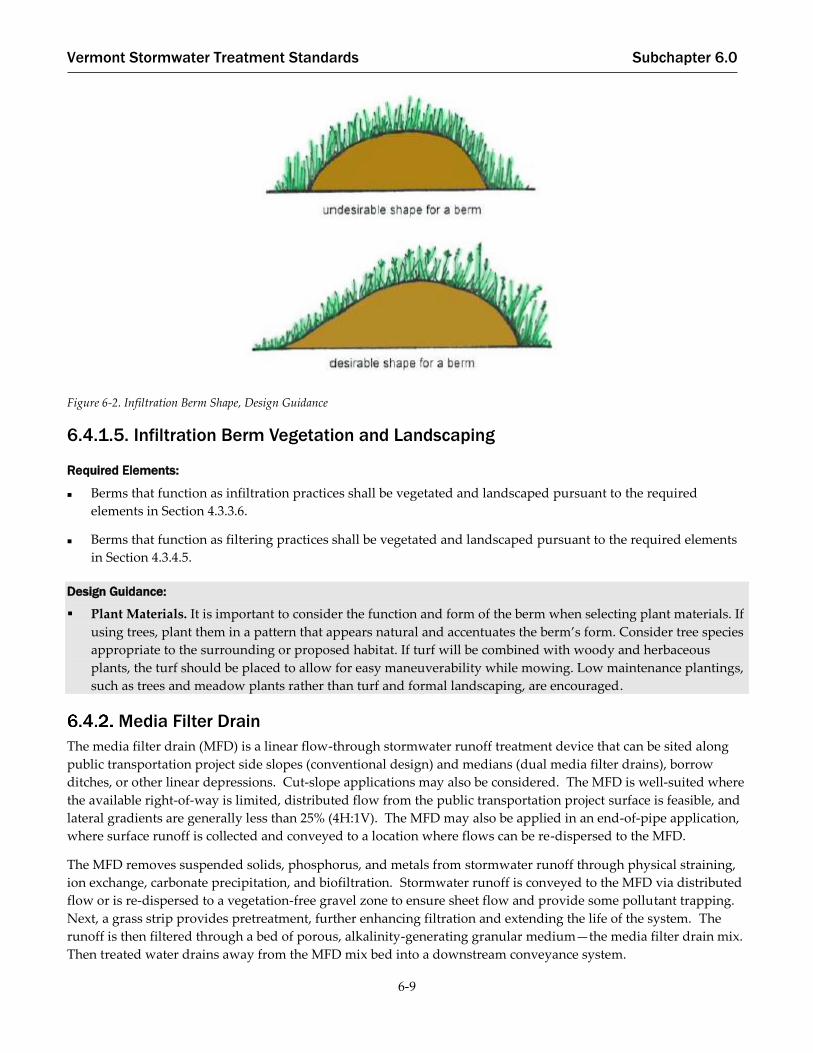
Vermont Stormwater Treatment Standards Subchapter 6.0
6-9
Figure 6-2. Infiltration Berm Shape, Design Guidance
6.4.1.5. Infiltration Berm Vegetation and Landscaping
Required Elements:
Berms that function as infiltration practices shall be vegetated and landscaped pursuant to the required
elements in Section 4.3.3.6.
Berms that function as filtering practices shall be vegetated and landscaped pursuant to the required elements
in Section 4.3.4.5.
Design Guidance:
▪ Plant Materials. It is important to consider the function and form of the berm when selecting plant materials. If
using trees, plant them in a pattern that appears natural and accentuates the berm’s form. Consider tree species
appropriate to the surrounding or proposed habitat. If turf will be combined with woody and herbaceous
plants, the turf should be placed to allow for easy maneuverability while mowing. Low maintenance plantings,
such as trees and meadow plants rather than turf and formal landscaping, are encouraged.
Media Filter Drain
The media filter drain (MFD) is a linear flow-through stormwater runoff treatment device that can be sited along
public transportation project side slopes (conventional design) and medians (dual media filter drains), borrow
ditches, or other linear depressions. Cut-slope applications may also be considered. The MFD is well-suited where
the available right-of-way is limited, distributed flow from the public transportation project surface is feasible, and
lateral gradients are generally less than 25% (4H:1V). The MFD may also be applied in an end-of-pipe application,
where surface runoff is collected and conveyed to a location where flows can be re-dispersed to the MFD.
The MFD removes suspended solids, phosphorus, and metals from stormwater runoff through physical straining,
ion exchange, carbonate precipitation, and biofiltration. Stormwater runoff is conveyed to the MFD via distributed
flow or is re-dispersed to a vegetation-free gravel zone to ensure sheet flow and provide some pollutant trapping.
Next, a grass strip provides pretreatment, further enhancing filtration and extending the life of the system. The
runoff is then filtered through a bed of porous, alkalinity-generating granular medium—the media filter drain mix.
Then treated water drains away from the MFD mix bed into a downstream conveyance system.
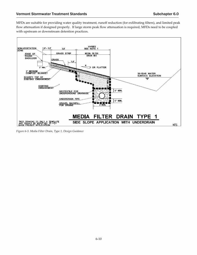
Vermont Stormwater Treatment Standards Subchapter 6.0
6-10
MFDs are suitable for providing water quality treatment, runoff reduction (for exfiltrating filters), and limited peak
flow attenuation if designed properly. If large storm peak flow attenuation is required, MFDs need to be coupled
with upstream or downstream detention practices.
Figure 6-3. Media Filter Drain, Type 1, Design Guidance

Vermont Stormwater Treatment Standards Subchapter 6.0
6-11
Figure 6-4. Media Filter Drain, Type 2, Design Guidance
6.4.2.1. Media Filter Drain Feasibility
Required Elements:
For use as an infiltration practice, underlying soils shall have an infiltration rate (fc) of at least 0.2 inches per
hour, as confirmed by soil testing requirements for infiltration pursuant to Section 4.3.3.2.
Shallow groundwater. Determine seasonal high groundwater table levels at the project site to ensure the MFD
mix bed and the underdrain, if applicable, will not become saturated by shallow groundwater. The hydraulic
and runoff treatment performance of the MFD may be compromised due to backwater effects and lack of
sufficient hydraulic gradient due to shallow groundwater or pooling at the discharge location. Vertical
separation from the bottom of the MFD and seasonal high groundwater or bedrock shall be the same as for
infiltration practices (Section 4.3.3.1) if designed to infiltrate, or as for filtering practices (Section 4.3.4.1) if lined
or underdrained.
MFDs shall only be used where the site can be reasonably designed to locate a MFD on lateral slopes less than
or equal to 25%.
Design Guidance:
Unstable slopes. In areas where slope stability may be problematic, consult a geotechnical engineer.
Narrow roadway shoulders. In areas where there is a narrow roadway shoulder (width less than 10 feet),
consider placing the MFD farther down the embankment slope. This will reduce the amount of rutting from
vehicles leaving the roadway shoulder in the MFD and decrease overall maintenance repairs.

Vermont Stormwater Treatment Standards Subchapter 6.0
6-12
6.4.2.2. Media Filter Drain Conveyance
Required Elements:
Water shall be conveyed to the MFD via sheet flow. Concentrated flows shall be re-dispersed prior to entering
the MFD.
Lateral MFD side slopes adjacent to the roadway pavement shall be equal to or less than 4H:1V. As side slopes
approach 3H:1V, without design modifications, sloughing may become a problem due to friction limitations
between the separation geotextile and underlying soils.
Longitudinal MFD slopes shall be no steeper than 5%.
The longest flow path from the contributing area delivering distributed flow to the MFD shall not exceed 150
feet.
6.4.2.3. Media Filter Drain Pre-Treatment
Required Elements:
No-Vegetation Zone. The no-vegetation zone (vegetation-free zone) is a shallow gravel zone located directly
adjacent to the public transportation project pavement. The no-vegetation zone functions as a level spreader to
promote distributed flow and a deposition area for coarse sediments. The no-vegetation zone shall be between
1 foot and 3 feet wide. Depth shall be a function of how the roadway section is built from subgrade to finish
grade; the resultant cross section will typically be triangular or trapezoidal. Within these bounds, the width
varies depending on VTrans or municipal maintenance spraying practices if applicable.
Grass Strip. The grass strip functions as additional pre-treatment and runoff velocity reduction for distributed
flow from the adjacent public transportation project surface. Pre-treatment is achieved through filtering and
limited infiltration. The width of the grass strip shall be dependent on the availability of space within the
public transportation side slope, but shall be 3 feet wide at a minimum. At a minimum, the existing
embankment shall be scarified 2 inches and covered with 4 inches of topsoil meeting the Post-Construction Soil
Depth and Quality Treatment Standard (Section 6.3) and seeded. Consider adding aggregate to the soil mix to
help minimize rutting problems from errant vehicles. The soil mix shall ensure grass growth for the design life
of the MFD.
Design Guidance:
To ensure sediment accumulation does not restrict distributed flow, edge of pavement installations should
include a 1-inch drop between the pavement surface and no-vegetation zone.
Grass strips wider than 3 feet are recommended if additional space is available within the right of way.
6.4.2.4. Media Filter Drain Treatment
Required Elements:
Credit toward Treatment Standards.
o For MFDs that are not designed to infiltrate, the treatment volume stored above and within the filter
media shall be credited towards WQV. MFDs that function as filters are Tier 2 Practices.
o For MFDs that function as infiltration practices, the treatment volume (TV) stored behind above and
within the filter media and infiltrated shall be credited towards WQV, CPV, QP10, and QP100. MFDs that
function as infiltration practices are Tier 1 Practices.

Vermont Stormwater Treatment Standards Subchapter 6.0
6-13
o Where TV credit for infiltration from the bottom of the filter bed to native soil is desired, the sizing
equation from the Media Filter Drain Mix Bed Sizing Procedure below should be combined with the
sizing equation for infiltration trenches (Section 4.3.3.5).
Components
o Media Filter Drain Mix Bed. The MFD mix is a mixture of crushed rock (sized by screening), dolomite,
gypsum, and perlite. The crushed rock provides the support matrix of the medium; the dolomite and
gypsum add alkalinity and ion exchange capacity to promote the precipitation and exchange of heavy
metals; and the perlite improves moisture retention to promote the formation of biomass within the MFD
mix. The combination of physical filtering, precipitation, ion exchange, and biofiltration enhances the
water treatment capacity of the mix. The permeability rate used to size the MFD shall be 10 inches per
hour.
o 4-Inch Medium Topsoil Blanket and Grass. Place a 4-inch medium topsoil blanket with grass over the
media filter drain bed area to reduce noxious weeds and unwanted vegetation. Topsoil shall meet
required elements of the Post-Construction Soil Depth and Quality Treatment Standard (Subchapter 3.0
and Section 6.3).
o Conveyance System below Media Filter Drain Mix. The gravel underdrain trench provides hydraulic
conveyance when treated runoff needs to be conveyed to a desired location such as a downstream flow
control STP or stormwater outfall. In Group C and D soils, an underdrain pipe helps ensure free flow of
the treated runoff through the MFD mix bed. In some Group A and B soils, an underdrain pipe may not
be necessary if most water percolates into subsoil from the underdrain trench. The need for underdrain
pipe shall be evaluated in all cases. The gravel underdrain trench may be eliminated if flows can be
conveyed laterally to an adjacent ditch or onto a fill slope that is properly vegetated to protect against
erosion. The MFD mix shall be kept free draining up to the 50-year storm event water surface elevation
represented in the downstream ditch.
Materials.
o The MFD mix shall include of the amendments listed in Table 6-1. Mixing and transportation shall occur
in a manner that ensures the materials are thoroughly mixed prior to placement and that separation does
not occur during transportation or construction operations.

Vermont Stormwater Treatment Standards Subchapter 6.0
6-14
Table 6-1. Media Filter Drain Mix
Amendment Quantity
Mineral Aggregate:
Shall meet all requirements in VTrans Standard Specification 704.11 – Aggregate for Bituminous Surface Treatment
with exception that the fracture requirement in 704.11(c) shall be at least two fractured faces.
Shall meet grading requirements for Stone Grits as shown in Table 704.11A.
3 cubic yards
Perlite:
Horticultural Grade shall be in pelletized or granular form.
Shall meet the following requirements for quality and grading:
Quality Requirements
Property Test Method1 Requirement
pH (of water slurry) PI 202 6.5-8.0
Bulk Density (lb/ft3) PI 200 2 -10
1PI, abbreviation for the Perlite Institute
Gradation Requirements
Sieve Size Percent Passing
No. 4 99-100
No. 18 30 max
No. 30 10 max
All percentages by weight
1 cubic yard per 3 cubic
yards of mineral
aggregate
Dolomite Lime: CaMg(CO3)2 (calcium magnesium carbonate)
Agricultural grade shall be in a pelletized or granular form meeting requirements of ASTM C 602 Class Designation E
40 pounds per cubic
yard of perlite
Gypsum: CaSO4●2H20 (hydrated calcium sulfate)
Agricultural grade shall be in a pelletized or granular form and shall meet the following grading requirements:
Sieve Size Percent Passing
¼” 99-100
No. 20 20 max
All percentages by weight
12 pounds per cubic
yard of perlite
o These materials shall be used in accordance with the following VTrans Standard Specifications:
o Drainage Aggregate – Section 704.16
o Underdrain Pipe – Sections 710.03 or 710.06
o Geotextile for Underdrain Trench Lining – Section 720.01
Design Method
Length (perpendicular to direction of flow).
o The length of the MFD shall be the same as the length of the contributing pavement.

Vermont Stormwater Treatment Standards Subchapter 6.0
6-15
Cross-Section.
o The surface of the MFD should have a lateral slope less than 4H:1V (<25%). On steeper terrain, it may be
possible to construct terraces to create a 4H:1V slope, or other engineering may be employed to ensure
slope stability up to 3H:1V.
o The resultant slope from the contributing drainage area should be less than or equal to 9.4%, calculated
using the following equation:
SCFS ≤ (G2 + e2)0.5
where:
𝑆𝐶𝐹𝑆 = resultant slope of the lateral and longitudinal slopes (%)
𝑒 = lateral slope (superelevation) (%)
𝐺 = longitudinal slope (grade) (%)
Media Filter Drain Mix Bed Sizing Procedure.
o The width of the MFD mix bed shall be determined by the amount of contributing pavement routed to
the embankment.
o The surface area of the MFD mix bed shall be sufficiently large to fully infiltrate and filter the runoff
treatment design flow rate using the long-term filtration rate of the MFD mix.
o For design purposes, a 50% safety factor shall be incorporated into the long-term MFD mix filtration rate
to accommodate variations in slope, resulting in a design filtration rate of 10 inches per hour.
o The MFD mix bed shall have a bottom width of at least 2 feet in contact with the conveyance system
below the MFD mix.
o The MFD mix bed shall be a minimum of 12 inches deep, including the section on top of the underdrain
trench.
o For runoff treatment, the sizing of the MFD mix bed shall be based on the requirement that the runoff
treatment flow rate from the pavement area, QHighway, cannot exceed the long-term infiltration capacity of
the MFD, QInfiltration.
o QHighway is the water quality volume peak flow rate as determined using TR-20 or an approved
equivalent. Water Quality Peak Flow Curve Number calculations apply when determining QHighway (see
Section 2.2.4.2).
o The long-term infiltration capacity of the MFD shall be based on the following equation:
LTIR x L x W
C x SF= QInfiltration
where:
𝐿𝑇𝐼𝑅 = long-term infiltration rate of the media filter drain mix (use 10 inches per hour for
design)
𝐿 = length of media filter drain (parallel to roadway) (ft.)
𝑊 = width of the media filter drain mix bed (ft.)
Equation 6-1
Equation 6-2
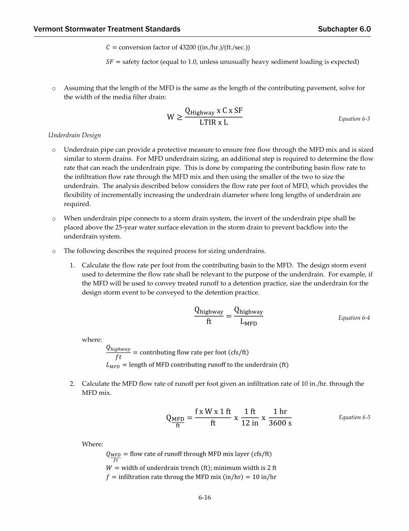
Vermont Stormwater Treatment Standards Subchapter 6.0
6-16
𝐶 = conversion factor of 43200 ((in./hr.)/(ft./sec.))
𝑆𝐹 = safety factor (equal to 1.0, unless unusually heavy sediment loading is expected)
o Assuming that the length of the MFD is the same as the length of the contributing pavement, solve for
the width of the media filter drain:
W ≥QHighway x C x SF
LTIR x L
Underdrain Design
o Underdrain pipe can provide a protective measure to ensure free flow through the MFD mix and is sized
similar to storm drains. For MFD underdrain sizing, an additional step is required to determine the flow
rate that can reach the underdrain pipe. This is done by comparing the contributing basin flow rate to
the infiltration flow rate through the MFD mix and then using the smaller of the two to size the
underdrain. The analysis described below considers the flow rate per foot of MFD, which provides the
flexibility of incrementally increasing the underdrain diameter where long lengths of underdrain are
required.
o When underdrain pipe connects to a storm drain system, the invert of the underdrain pipe shall be
placed above the 25-year water surface elevation in the storm drain to prevent backflow into the
underdrain system.
o The following describes the required process for sizing underdrains.
1. Calculate the flow rate per foot from the contributing basin to the MFD. The design storm event
used to determine the flow rate shall be relevant to the purpose of the underdrain. For example, if
the MFD will be used to convey treated runoff to a detention practice, size the underdrain for the
design storm event to be conveyed to the detention practice.
Qhighway
ft=
Qhighway
LMFD
where: 𝑄ℎ𝑖𝑔ℎ𝑤𝑎𝑦
𝑓𝑡= contributing flow rate per foot (cfs/ft)
𝐿𝑀𝐹𝐷 = length of MFD contributing runoff to the underdrain (ft)
2. Calculate the MFD flow rate of runoff per foot given an infiltration rate of 10 in./hr. through the
MFD mix.
QMFDft
=f x W x 1 ft
ft x
1 ft
12 in x
1 hr
3600 s
Where:
𝑄𝑀𝐹𝐷𝑓𝑡
= flow rate of runoff through MFD mix layer (cfs/ft)
𝑊 = width of underdrain trench (ft); minimum width is 2 ft
𝑓 = infiltration rate throug the MFD mix (in/hr) = 10 in/hr
Equation 6-3
Equation 6-4
Equation 6-5

Vermont Stormwater Treatment Standards Subchapter 6.0
6-17
3. Size the underdrain pipe to convey the runoff that can reach the underdrain trench. This is taken
to be the smaller of the contributing basin flow rate or the flow rate through the MFD mix layer.
QUDft
= smaller {Qhighwayft
or QMFD
ft
}
Where:
𝑄𝑈𝐷𝑓𝑡
= underdrain design flow rate per foot (cfs/ft)
4. Determine the underdrain design flow rate using the length of the MFD and a factor of safety of
1.2.
QUD = 1.2 x QUDft
x W x LMFD
Where:
𝑄𝑈𝐷 = estimated flow rate to the underdrain (cfs)
𝑊 = width of underdrain trench; minimum width is 2 ft
𝐿𝑀𝐹𝐷 = length of MFD contributing runoff to the underdrain (ft)
5. Given the underdrain design flow rate, determine the underdrain diameter. Round pipe diameters
to the nearest standard pipe size and have a minimum diameter of 6 inches.
D = 16 ((QUD x n)
s0.5)
3/8
Where:
𝐷 = underdrain pipe diameter (inches)
𝑛 = Manning′s coefficient
𝑠 = slope of pipe (ft/ft)
6.4.2.5. Media Filter Drain Vegetation and Landscaping
Required Elements:
Landscape the grass strip using the required elements for Pre-Treatment Filter Strips (Section 4.1.2).
Topsoil shall meet the requirements of Subchapter 3.0 and Section 6.3.
Equation 6-6
Equation 6-7
Equation 6-8

Vermont Stormwater Treatment Standards Subchapter 6.0
6-18
Runoff Control Measures for Public Transportation Project Redevelopment – Major Maintenance Projects
The BMPs below, referred to in this section as measures, are available for use on Redevelopment-Major
Maintenance projects. These measures shall be considered for implementation to improve pre-existing stormwater
runoff conditions within existing rights-of-way or if possible, outside of the right-of-way. Where existing swales,
vegetated shoulders, median areas, and discharge points within existing rights-of-way or drainage easements can
be retrofitted with these measures without adversely affecting safety or the integrity of the public transportation
project, measures shall be designed to disconnect, capture and infiltrate, or evapotranspire water quality volume
from impervious areas, and to reduce or eliminate existing erosion issues, to the extent practicable.
Runoff control measures in this Section may be implemented on any project, but all new impervious areas subject
to Stormwater Treatment Standards shall be treated with STPs in Subchapter 4.0 or Section 3.0 and pursuant to the
requirements of this Manual.
Modifications to Acceptable STPs
Any STP contained in Subchapter 4.0 or Section 6.4 may be used to treat and manage stormwater from
Redevelopment-Major Maintenance impervious surfaces. They should be designed to meet sizing requirements if
practical. If sizing for the full treatment standard is impractical within the right-of-way or project limits, these STPs
may be sized to fit within project constraints as long as safe conveyance of larger storm flows can be maintained.
Plunge Pools
Plunge pools are pre-shaped, stone-lined basins located directly downgrade of a discharge point. The man-made
structure mimics the natural scour hole that would otherwise form at the conveyance outlet if no energy
dissipation were provided. The pool is stabilized with riprap underlain by a gravel layer (or filter fabric in clay and
silt soils) to absorb the impact of the discharge, prevent additional erosion and allow suspended particles to settle
trapping trash and debris. Once runoff has filled the shallow basin, it overtops the plunge pool and is redistributed
as diffuse flow to the surrounding area.
Plunge pools absorb the impact of high velocities and reduce the potential for downgrade erosion from point
discharges by reducing flow velocities. When plunge pools are implemented under small peak flow conditions
Source: NCDOT 2014
Figure 6-5. Plunge Pools, Design Guidance

Vermont Stormwater Treatment Standards Subchapter 6.0
6-19
and installed on level ground, they redistribute concentrated inflow to diffuse outflow to adjacent land. Plunge
pools provide a water quality benefit by dispersing flow, which achieves the following:
Prevents scour at the pipe discharge
Promotes runoff infiltration
Reduces soil erosion
6.5.2.1. Plunge Pool Design
Required Elements:
To prevent erosion immediately downgrade of the plunge pool, an apron of permanent soil reinforcement
matting (PSRM) is required downgrade of the measure.
Source: NCDOT 2014
Figure 6-6. Plunge Pool (Plan), Design Guidance (Source: NCDOT 2014)
Figure 6-7. Plunge Pool (Profile), Design Guidance (Source: NC DOT 2014)

Vermont Stormwater Treatment Standards Subchapter 6.0
6-20
Design Guidance:
Plunge pools can be used for energy dissipation and diffuse flow in a variety of man-made conveyance
systems. For a plunge pool to perform both functions, specific conditions must exist. Most importantly, the
ground downgrade must be flat to prevent re-concentration of runoff. To redistribute runoff from channelized
flow to diffuse flow, plunge pools should be implemented only for (Q10) peak flows of 10 ft3/s or less. If diffuse
flow is desired and either (1) the Q10 peak flow is greater than 10 ft3/s or (2) the site slope is not relatively flat
(<5%), additional requirements apply. Alternatively, the designer could consider the use of a level spreader. If
diffuse flow is not desired, then plunge pools need to outlet to a stable channel or other conveyance without
causing downstream erosion.
For plunge pools with swale inlets, the swale should be flared around the plunge pool to match the pool width.
Circular plunge pools are typically used only with pipes
Plunge pools located in residential or public areas may present a drowning hazard. Consider fencing and
signage around the area to ensure safety.
Required Elements (for pipes ≤ 18” diameter and flows ≤ 9 ft3/s):
The downstream area shall be flat (<5%) if diffuse flow is a goal. For slopes greater than 5%, outlet to a stable
channel or other stable conveyance shall be provided.
The maximum allowable discharge for a 15-in. pipe is 6 ft3/s, based on the QP10 discharge.
The maximum allowable discharge for an 18-in. pipe is 10 ft3/s, based on the Q10 discharge.
For 15-in. and 18-in. pipes, only Type II Stone Fill (d50 = 12 in.), VTrans Standard Specification 706.04(b), shall be
used to line the plunge pool. This specification is based on empirical relationships between the area of the
discharge pipe and the stone fill d50 and unsuccessful applications of smaller stone fill sizes. A d50 of 12 inches
allows for a minimum pool depth of approximately 1 foot and a maximum depth of 3 feet. The minimum and
maximum stone sizes for Type II Stone Fill are 2 inches to 36 inches, respectively.
Stone fill thickness and other design requirements of Section 5.3.2 of the VTrans Hydraulics Manual, 2015
apply.
The base of the plunge pool is square. The width is calculated as follows:
o Base width = 3 × Discharge pipe size
Minimum width of the PSRM apron is the standard PSRM roll width.
PSRM shall be tucked a minimum of 1 foot underneath the filter fabric and natural ground around the
perimeter of the plunge pool.
Side slopes for all four sides of the plunge pool is no greater than 2:1.
Minimum depth of the plunge pool is 1 foot.
Maximum depth of the plunge pool is 3 feet.
Design Guidance (for pipes ≤ 18” diameter and flows ≤ 9 ft3/s):
Where diffuse flow is a primary goal, plunge pools must be installed level in relatively flat areas. To avoid
shifting of the plunge pool after installation, the plunge pool should be installed in undisturbed soil instead of
in fill material.

Vermont Stormwater Treatment Standards Subchapter 6.0
6-21
Confirm that the location of the plunge pool is outside of clear recovery zones and environmentally sensitive
areas.
Check the available right-of-way when determining the plunge pool footprint and orientation.
Confirm that the apron is flush with the natural ground. The elevation of the top of the plunge pool should be
the same as the elevation of the PSRM.
Confirm that riprap consists of a well-graded mixture of stone. Smaller-size riprap stones should be used to fill
voids between larger stones.
Where practical, route off-site runoff away from the plunge pool.
Immediately after construction, stabilize the exit areas with vegetation. Clear the area of all construction debris
and check the exit areas for any potential obstructions that could promote channelized flow.
When selecting the plunge pool location, the designer must take into account topography. The plunge pool
should be oriented to conform to the contours of the site. Typically, the plunge pool is placed at the highway
drainage system outlet. Alternatives should be considered when steep slopes are located at a discharge point.
For example, a riprap lined channel can be constructed at a pipe outlet to then discharge into a plunge pool.
This method is sometimes applied in gore areas at highway interchanges.
Confirm that the plunge pool has easy access for maintenance.
Required Elements (additional for pipes > 18” diameter and flows > 9 ft3/s):
The size of the stone fill shall be selected using the design criteria of Section 5.3.2 of the VTrans Hydraulics
Manual, 2015.
The filter fabric shall be placed between the riprap and soil foundation to prevent soil movement through the
openings of riprap.
Design Guidance (additional, for pipes > 18” diameter and flows > 9 ft3/s):
Contributing drainage area should be delineated to determine the QP10 discharge.
The plunge pool size should be based on the volume associated with 0.1 inches of runoff for the impervious
area within the contributing drainage area. Once the volume is determined, the plunge pool configuration is
determined.
Rectangular plunge pools should have a minimum length-to-width ratio of 2:1, where practical, to promote
sedimentation, with a maximum ratio of 6:1.
Rectangular plunge pools width should be a minimum of 3 feet. Circular plunge pools should have a minimum
diameter of 5 feet.
Depth of the plunge pool should be between 3 and 5 feet.
Plunge pool side slopes should be flatter than or equal to 2:1
Transition berms should have a minimum top width of 5 feet (in the direction of flow).
Outflow control structures should be considered to reduce peak flows to downstream conveyances or receiving
waters.
The transition berm between the plunge pool and the downstream STP, conveyance or receiving water should
be made of a non-erodible material designed to minimize exit velocities and diffuse flow downstream.

Vermont Stormwater Treatment Standards Subchapter 6.0
6-22
Check Dams
Water quality check dams are permanent structures that reduce the effective slope of a conveyance swale, and
create small pools, dissipating the energy of flow, increasing hydraulic residence time, allowing suspended
particles to settle trapping trash and debris, and promoting infiltration. The check dams should be used in series,
with the toe of the upstream check dam at the same elevation as the top of the downstream check dam.
6.5.3.1. Check Dam Feasibility
Required Elements:
Check dams shall not be installed in live streams or channels.
Figure 6-8. Plunge Pool, Rectangular (Plan View) Design Guidance (Source: NCDOT 2014)
Figure 6-9. Plunge Pool, Rectangular (Profile View), Design Guidance (Source: NCDOT 2014)

Vermont Stormwater Treatment Standards Subchapter 6.0
6-23
Design Guidance:
Check dams can be used in most conveyance swales, ditches, and channels. Check dams should be used where
conveyances discharge directly to receiving waters to promote sedimentation, infiltration, and energy
dissipation. Check dams, in effect, reduce the slope in drainage ways. This may lead to an overall reduction in
the capacity of the drainage way. This capacity reduction should be considered, so that the flows within the
drainage way do not exceed volume capacities.
6.5.3.2. Check Dam Design
Required Elements:
Check dams shall be spaced based on the channel slope. Spacing shall be pursuant to the requirements in the
Vermont Standards and Specifications for Erosion Prevention and Sediment Control (2006 or most recent
edition).
The maximum check dam height is 24 inches (for maintenance purposes).
Check dam materials shall be designed appropriately for the design channel velocities.
Armoring may be needed at the downstream toe of the check dam to prevent erosion.
Check dams shall be firmly anchored into the side-slopes to prevent outflanking; check dams shall also be
anchored into the channel bottom so as to prevent hydrostatic head from pushing out the underlying soils.
Maximum water elevation in channel (for 10-year design storm) shall be compared against anchoring height of
check dam to ensure outflanking does not occur.
Check dams shall be designed with a center weir sized to pass the channel design storm peak flow (10-year
storm event for man-made channels). Capacity of the drainage conveyance shall be checked to ensure storm
flows can pass with at least 6” of freeboard for a 10-year storm.
Design Guidance:
The check dam should be designed so that it facilitates mowing and maintenance.
Each check dam should have a weep hole or similar drainage feature so it can dewater after storms.
Check dams should be composed of wood, concrete, stone, or other non-erodible material, or should be
configured with elevated driveway culverts.
Individual channel segments formed by check dams or driveways should generally be at least 25 to 40 feet in
length.
Figure 6-10. Check Dam (Profile), Design Guidance

Vermont Stormwater Treatment Standards Subchapter 6.0
6-24
Figure 6-11. Check Dam (Detail), Design Guidance
6.5.3.3. Check Dam Safety Considerations
Required Elements:
Check dams shall be installed in channels such that either they are located outside of the clear zone of the
public transportation project or they do not constitute a roadside hazard.

Vermont Stormwater Treatment Standards Subchapter 7.0
7-1
7.0 DEFINITIONS
As used in this Manual, the following terms shall have the specified meaning, unless a different meaning is clearly
intended by the context. If a term is not defined, it shall have its common meaning.
“1-year storm” means a storm event which has a 1-year recurrence interval or statistically has a 100% chance on
average of occurring in a given year.
“10-year storm” means a storm event which has a 10-year recurrence interval or statistically has a 10% chance of
occurring in a given year.
“100-year storm” means a storm event which has a 100-year recurrence interval, or statistically has a 1% chance on
average of occurring in a given year.
“Agency” means the Vermont Agency of Natural Resources.
“Anti-seep collar” means an impermeable diaphragm usually of sheet metal or concrete constructed at intervals
within the zone of saturation along the conduit of a principal spillway to increase the seepage length along the
conduit and thereby prevent piping or seepage along the conduit.
“Applicant” means a person applying for permit coverage. In some cases, more than one person may apply as co-
applicants.
“Aquatic bench” means a 10 to 15-foot-wide bench which is located around the inside perimeter of a stormwater
pond permanent pool and is normally vegetated with aquatic plants; the goal is to provide pollutant removal and
enhance safety in areas using stormwater ponds.
“Aquifer” means a geological formation that contains and transports groundwater.
“Authorization to discharge” means an authorization to discharge issued by the Secretary pursuant to a general
permit.
“Baffles” means guides, grids, grating or similar devices placed in a pond to deflect or regulate flow and create a
longer flow path.
“Barrel” means the closed conduit used to convey water under or through an embankment: part of the principal
spillway.
“Berm” means a shelf that breaks the continuity of a slope; a linear embankment or dike.
“BMP” or “best management practice” means a schedule of activities, prohibitions or practices, maintenance
procedures, green infrastructure, and other management practices to prevent or reduce water pollution, including
the STPs set forth in this Manual.
“Channel” means a natural stream that conveys water; a ditch or swale excavated for the flow of water.
“Channel Protection Standard,” “channel protection,” or “CPV” means the design criteria in this Manual that
requires management of the post-development stormwater runoff from the 1-year, 24-hour storm event for the
control of stream channel erosion.
“Check dam” means a small dam constructed in a gully, swale, or other channel to decrease the flow velocity, by
reducing the channel gradient; minimize channel scour; and promote deposition of sediment. Check dams may be
constructed of wood, small diameter stone, concrete, or earth.
“Chute” means a high velocity, open channel for conveying water to a lower level without erosion.

Vermont Stormwater Treatment Standards Subchapter 7.0
7-2
“Clay” or “clay soil” means: (1) a mineral soil consisting of particles less than 0.002 millimeter in equivalent
diameter, (2) a soil texture class, or (3) for engineering, a fine-grained soil (more than 50 percent passing the No. 200
sieve) that has a high plasticity index in relation to the liquid limit
“CN” see definition of “curve number.”
“Common plan of development” means a development that is completed in phases or stages when such phases or
stages share a common state or local permit related to the regulation of land use, the discharge of wastewater or a
discharge to surface waters or groundwater, or a development designed with shared common infrastructure.
Common plans of development include subdivisions, industrial and commercial parks, university and other
campuses, and ski areas.
“Compaction” means any process by which the soil grains are rearranged to decrease void space and bring them in
closer contact with one another, thereby increasing the weight of solid material per unit of volume, increasing the
shear and bearing strength and reducing permeability.
“Conduit” means any channel intended for the conveyance of water, whether open or closed.
“Contour” means: (1) an imaginary line on the surface of the earth connecting points of the same elevation, or (2) a
line drawn on a map connecting points of the same elevation.
“CPV” see definition of “Channel Protection Standard.”
“Crest” means the top of a dam, dike, spillway, or weir, frequently restricted to the overflow portion.
“Curve number” or “CN” means a numerical representation of a given area’s hydrologic soil group, plant cover,
impervious cover, interception and surface storage derived in accordance with Natural Resources Conservation
Service methods. This number is used to convert rainfall volume into runoff volume.
“Cut” means a portion of land surface or area from which earth has been removed or will be removed by
excavation; the depth below original ground surface to excavated surface.
“Cut-and-fill” means a process of earth moving by excavating part of an area and using the excavated material for
adjacent embankments or fill areas.
“Cutoff” means a wall or other structure, such as a trench, filled with relatively impervious material intended to
reduce seepage of water through porous strata.
“Dam” means a barrier to confine or raise water for storage or diversion, to create a hydraulic head, to prevent
gully erosion, or for retention of soil, sediment, or other debris.
“Department” means the Vermont Department of Environmental Conservation.
“Detention” means the temporary storage of stormwater runoff in a STP with the goals of controlling peak
discharge rates and providing gravity settling of pollutants.
“Detention structure” means a structure constructed for the purpose of temporary storage of stream flow or
surface runoff and gradual release of stored water at controlled rates.
“Development” means the construction of impervious surface on a tract or tracts of land.
“Dike” means an embankment to confine or control water.
“Discharge” means the placing, depositing, or emission of any wastes, directly or indirectly, into an injection well
or into the waters of the State.
“Disturbance” means removal of stable surface treatment leaving exposed soil susceptible to erosion.

Vermont Stormwater Treatment Standards Subchapter 7.0
7-3
“Disturbed area” means an area in which the natural vegetative or other soil cover has been removed or altered
and, therefore, is susceptible to erosion.
“Diversion” means a channel with a supporting ridge on the lower side constructed across the slope to divert
water from areas where it is in excess to sites where it can be used or disposed of safely. Diversions differ from
terraces in that they are individually designed.
“Drainage” means: (1) the removal of excess surface water or groundwater from land by means of surface or
subsurface drains, or (2) soil characteristics that affect natural drainage.
“Drainage area” means all land and water area from which runoff may run to a common (design) point.
“ED” see definition of “extended detention.”
“Emergency spillway” means a dam spillway designed and constructed to discharge flow in excess of the principal
spillway design discharge.
“Energy dissipator” means a designed device such as an apron of rip-rap or a concrete structure placed at the end
of a water transmitting apparatus such as pipe, paved ditch, or paved chute for the purpose of reducing the
velocity, energy, and turbulence of the discharged water.
“Exceptional Quality biosolids” or “EQ biosolids” means sludges or biosolids that have been subjected to
an advanced pathogen reduction treatment process and meet the vector attraction and pollutant
concentration standards such that they are no longer classified as a solid waste pursuant to §6-301(b)(5) of
the Solid Waste Management Rules, and may be marketed and distributed to the general public for use
without a site-specific permit.
“Erosion” means: (1) the wearing away of the land surface by running water, wind, ice, or other geological agents,
including such processes as gravitational creep, or (2) detachment and movement of soil or rock fragments by
water, wind, ice, or gravity. The following terms are used to describe different types of water erosion:
“Accelerated erosion” means erosion much more rapid than normal, natural, or geologic erosion,
primarily as a result of the influence of the activities of man or, in some cases, of other animals or natural
catastrophes that expose base surfaces, for example, fires.
“Gully erosion” means the erosion process whereby water accumulates in narrow channels and, over short
periods, removes the soil from this narrow area to considerable depths, ranging from 1 or 2 feet to as much
as 75 to 100 feet.
“Rill erosion” means an erosion process in which numerous small channels only several inches deep are
formed.
“Sheet erosion” means the spattering of small soil particles caused by the impact of raindrops on wet soils.
The loosened and spattered particles may or may not subsequently be removed by surface runoff.
“Erosive velocities” means velocities of water that are high enough to wear away the land surface. Exposed soil
will generally erode faster than stabilized soils. Erosive velocities will vary according to the soil type, slope,
structural, or vegetative stabilization used to protect the soil.
“Exfiltration” means the downward movement of water through the soil; the downward flow of runoff from the
bottom of an infiltration STP into the soil.
“Existing impervious surface” means an impervious surface that is in existence, regardless of whether it ever
required a stormwater discharge permit.

Vermont Stormwater Treatment Standards Subchapter 7.0
7-4
“Expansion” and “expanded portion” means an increase or addition of new impervious surface to an existing
impervious surface, such that the total resulting impervious surface is greater than the minimum regulatory
threshold.
“Extended detention” or “ED” means a stormwater design feature that provides for the gradual release of a
volume of water over a period of time as specified in this Manual, to increase settling of pollutants and protect
downstream channels from frequent storm events.
“Extended Detention Method” means a method for meeting the Channel Protection Standard for those sites where
the practice or suite of practices is insufficient to achieve the HCM for meeting Channel Protection Standard.
“Extreme Flood Protection Standard,” “extreme flood control,” or “QP100” means the design criteria in this Manual
that requires management of the post-development stormwater runoff from the 100-year, 24-hour storm event for
the control of overbank flooding that results from that storm event.
“Filter bed” means the section of a constructed filtration device that houses the filter media and the outflow pipes.
“Filter media” means the sand, soil, or other material in a filtration device used to provide a permeable surface for
pollutant and sediment removal.
“Fines” means the silt- and clay-size particles in soil.
“Flow splitter” means an engineered, hydraulic structure designed to divert a percentage of storm flow to a STP
located out of the primary channel, or to direct stormwater to a parallel pipe system, or to bypass a portion of
baseflow around a STP.
“Freeboard” means the distance between the maximum water surface elevation anticipated in design and the top
of retaining banks or structures. Freeboard is provided to prevent overtopping due to unforeseen conditions.
“French drain” means a type of drain consisting of an excavated trench refilled with pervious material, such as
coarse sand, gravel, or stone, through whose voids water percolates and flows to an outlet.
“Grade” means: (1) the slope of a road, channel, or natural ground, (2) the finished surface of a canal bed, roadbed,
top of embankment, or bottom of excavation; any surface prepared for the support of construction, like paving or
laying a conduit, or (3) to finish the surface of a canal bed, roadbed, top of embankment, or bottom of excavation.
“Gravel” means: (1) aggregate consisting of mixed sizes of 1/4 inch to 3-inch particles that normally occur in or
near old streambeds and have been worn smooth by the action of water, or (2) a soil having particle sizes,
according to the Unified Soil Classification System, ranging from the No. 4 sieve size angular in shape as produced
by mechanical crushing.
“Ground cover” means plants that are low growing and provide a thick growth that protects the soil as well as
providing some beautification of the area occupied.
“Groundwater Recharge Standard”, “Recharge Volume”, or “Rev” means a design criterion that requires
infiltration of the recharge volume to ensure annual average recharge rates are maintained at a development site to
preserve existing water table elevations.
“Gully” means a channel or miniature valley cut by concentrated runoff through which water commonly flows
only during and immediately after heavy rains or during the melting of snow. The distinction between a gully and
a rill is one of depth. A gully is sufficiently deep that it would not be obliterated by normal tillage operations,
whereas a rill is of lesser depth and would be smoothed by ordinary farm tillage.
“HCM” see definition of “Hydrologic Condition Method.”

Vermont Stormwater Treatment Standards Subchapter 7.0
7-5
“HCV” or “hydrologic condition volume” means the difference between the pre-development and post-
development site runoff volume for the 1-year, 24-hour storm.
“Head” means: (1) the height of water above any plane of reference, or (2) the energy, either kinetic or potential,
possessed by each unit weight of a liquid expressed as the vertical height through which a unit weight would have
to fall to release the average energy possessed. “Head” is used in various terms such as “pressure head,” “velocity
head,” and “head loss.”
“Healthy soil” means soil that has a well-developed, porous structure, is chemically balanced, supports diverse
microbial communities, and has abundant organic matter.
“High marsh” means a pondscaping zone within a stormwater wetland that exists from the surface of the normal
pool to a 6-inch depth and typically contains the greatest density and diversity of emergent wetland plants.
“Hotspot” means an area where land use or activities generate highly contaminated runoff, with concentrations of
pollutants in excess of those typically found in stormwater.
“HSG” see definition of “hydrologic soil group.”
“Hydraulic gradient” means the slope of the hydraulic grade line. The slope of the free surface of water flowing in
an open channel.
“Hydrograph” means a graph showing variation in stage (depth) or discharge of a stream of water over a period of
time.
“Hydrologic Condition Method” or “HCM” means a method for meeting the Channel Protection Standard,
intended to determine a suite of practices, which when implemented, will approximate runoff characteristics of
“woods in good condition” for the 1-year, 24-hour storm event.
“Hydrologic soil group” or “HSG” means a Natural Resource Conservation Service classification system in which
soils are categorized into four runoff potential groups. The groups range from A soils, with high permeability and
little runoff production, to D soils, which have low permeability rates and produce much more runoff.
“Hydroseed” means seed or other material applied to areas to revegetate them after a disturbance.
“Impervious surface” or “I” means those manmade surfaces, including paved and unpaved roads, parking areas,
roofs, driveways, and walkways, from which precipitation runs off rather than infiltrates
“Infiltration rate” or “(fc)” means the rate at which stormwater percolates into the subsoil measured in inches per
hour.
“Manual” see definition of “Vermont Stormwater Management Manual.”
“Microtopography” means the complex contours along the bottom of a shallow marsh system, providing greater
depth variation, which increases the wetland plant diversity and increases the surface area to volume ratio of a
stormwater wetland.
“Mulch” means a covering on the surface of soil to protect and enhance certain characteristics, such as water
retention qualities.
“Municipality” means an incorporated city, town, village, or gore, a fire district established pursuant to state law,
or any other duly authorized political subdivision of the State.
“New development” means the construction of new impervious surface on a tract or tracts of land where no
impervious surface previously existed.
“Normal depth” means depth of flow in an open conduit during uniform flow for the given conditions.

Vermont Stormwater Treatment Standards Subchapter 7.0
7-6
“Off-line” means a stormwater management system designed to manage a storm event by diverting a percentage
of stormwater events from an STP or storm drainage system.
“Off-site” means land within a project’s drainage area that is not characterized as being part of the site.
“On-line” means a stormwater management system designed to manage stormwater in a STP or storm drainage
system without diversion.
“Outfall” means the point where water flows from a conduit, stream, or drain.
“Outlet” means the point at which water discharges from a, pipe, channel, or drainage area.
“Overbank Flood Protection Standard, “overbank flood control,” or “QP10” means the design criteria in this
Manual that requires management of the post-development stormwater runoff from the 10-year, 24-hour storm
event for the control of overbank flooding that results from that storm event.
“Peak discharge rate” means the maximum instantaneous rate of flow during a storm, usually in reference to a
specific design storm event.
“Permanent seeding” means establishing perennial vegetation that may remain on the area for many years.
“Permeability” means the rate of water movement through the soil column under saturated conditions
“Person” means any individual, partnership, company, corporation, association, joint venture, trust, municipality,
the state of Vermont, or any agency, department or subdivision of the State, any federal agency, or any other legal
or commercial entity.
“pH” means a number denoting the common logarithm of the reciprocal of the hydrogen ion concentration. A pH
of 7.0 denotes neutrality, higher values indicate alkalinity, and lower values indicate acidity.
“Pond drain” means a pipe or other structure used to drain a permanent pool within a specified time period.
“Pondscaping” means landscaping around stormwater ponds that emphasizes native vegetative species to meet
specific design intentions. Species are selected for up to six zones in the pond and its surrounding buffer, based on
their ability to tolerate inundation or soil saturation.
“Porosity” means the ratio of pore volume to total solids volume.
“Post-Construction Soil Depth and Quality Standard” means the suite of practices and management techniques
required under this Manual that pertain to restoring healthy soils after soils are subject to compaction and other
impacts incurred during construction. “Pre-treatment” means techniques employed in STPs to provide storage or
filtering to help trap coarse materials before they enter the system.
“Principal spillway” means the primary pipe or weir that carries baseflow and storm flow through the
embankment.
“Project” means new development, expansion, or redevelopment of impervious surface.
“Public transportation project” means a state highway project, town highway project, or other public road project;
or a linear public transportation project, such as a trail, bicycle path, or sidewalk project.
“Q10” see definition of “10-year storm.”
“Q100” see definition of “100-year storm.”
“QP10” see definition of “Overbank Flood Control Standard”.
“QP100” see definition of “Extreme Flood Protection Standard”.
Vermont Stormwater Treatment Standards Subchapter 7.0
7-7
“Recharge rate” means annual amount of rainfall that contributes to groundwater as a function of hydrologic soil
group.
“Redevelopment” or “redevelop” means the construction or reconstruction of an impervious surface where an
impervious surface already exists when such new construction involves substantial site grading, substantial
subsurface excavation, or substantial modification of existing stormwater conveyance, such that the total of
impervious surface to be constructed or reconstructed is greater than the minimum regulatory threshold.
Redevelopment does not mean public road management activities on impervious surfaces, including any crack
sealing, patching, coldplaning, resurfacing, paving a gravel road, reclaiming, or grading treatments used to
maintain pavement, bridges and unpaved roads. Redevelopment does not include expansions.
“Regulated stormwater runoff” means precipitation, snowmelt, and the material dissolved or suspended in
precipitation and snowmelt that runs off impervious surfaces and discharges into surface waters or into
groundwater via infiltration.
“Retention” means the amount of precipitation on a drainage area that does not escape as runoff. It is the
difference between total precipitation and total runoff.
“Reverse slope pipe” means a pipe which draws from below a permanent pool extending in a reverse angle up to
the riser and which determines the water elevation of the permanent pool.
“Right-of-way” means right of passage, as over another’s property. A route that is lawful to use. A strip of land
acquired for transport or utility construction.
“Rip-rap” means broken rock, cobbles, or boulders placed to prevent erosion.
“Riser” means a vertical pipe that extends from the bottom of a pond STP and houses the control devices
(weirs/orifices) to achieve the discharge rates for specified designs.
“Runoff coefficient” or “RV” means a value derived from a site impervious cover value that is applied to a given
rainfall volume to yield a corresponding runoff volume.
“Safety bench” means a flat area above the permanent pool and surrounding a stormwater pond designed to
provide a separation from the pond pool and adjacent slopes.
“Sand” means: (1) (Agronomy) a soil particle between 0.05 and 2.0 millimeters in diameter, (2) a soil textural class,
or (3) (Engineering) according to the Unified Soil Classification System, a soil particle larger than the No. 200 sieve
(0.074mm) and passing the No. 4 sieve (approximately 1/4 inch).
“Secretary” means the Secretary of the Agency of Natural Resources or the Secretary’s duly authorized
representative.
“Sediment” means solid material, both mineral and organic, that is in suspension, is being transported, or has been
moved from its site of origin by air, water, gravity, or ice and has come to rest on the earth’s surface either above or
below sea level.
“Seepage” means (1) water escaping through or emerging from the ground, or (2) the process by which water
percolates through the soil.
“Seepage length” means in sediment basins or ponds, the length along the pipe and around the anti-seep collars
that is within the seepage zone through an embankment.
“Sheet flow” means water, usually stormwater runoff, flowing in a thin layer over the ground surface.
“SHGWT” means seasonal high groundwater table.

Vermont Stormwater Treatment Standards Subchapter 7.0
7-8
“Side slopes” means the slope of the sides of a channel, dam, or embankment. It is customary to name the
horizontal distance first, as 3 to 1, or frequently, 3:1, meaning a horizontal distance (H) of 3 feet to 1 foot vertical
(V).
“Silt” means: (1) (Agronomy) a soil separate consisting of particles between 0.05 and 0.002 millimeter in equivalent
diameter, (2) a soil textural class, or (3) (Engineering) according to the Unified Soil Classification System a fine-
grained soil (more than 50 percent passing the No. 200 sieve) that has a low plasticity index in relation to the liquid
limit.
“Site” means either the drainage area that includes all portions of a project contributing stormwater runoff to one
or more discharge points, or the area that includes all portions of disturbed area within a project contributing
stormwater runoff to one or more discharge points. The choice of either of these two methods of calculating the
site area shall be at the discretion of the designer. In cases where there are multiple discharges to one or more
waters, “site” shall mean the total area of the sub-watersheds. For linear projects, including highways, roads and
streets, the term “site” includes the entire right of way within the limits of the proposed work, or all portions of
disturbed area within the right-of-way associated with the project. The method of calculating the site area for
linear projects shall be at the discretion of the designer. Calculations of a site are subject to the Secretary’s review.
“Soil Piping” means removal of soil material through subsurface flow channels or “pipes” developed by seepage
water.
“Spillway” means an open or closed channel, or both, used to convey excess water from a reservoir. It may
contain gates, either manually or automatically controlled to regulate the discharge of excess water.
“Stabilization” means providing adequate measures, vegetative or structural that will prevent erosion from
occurring.
“Stage” means, for purposes of hydraulics, the variable water surface or the water surface elevation above any
chosen datum.
“Stilling basin” means an open structure or excavation at the foot of an outfall, conduit, chute, drop, or spillway to
reduce the energy of the descending stream of water.
“Stone diaphragm” means a stone trench filled with small stone used as pre-treatment and inflow regulation in
stormwater filtering systems.
“Stone trench” means a shallow excavated channel backfilled with stone and designed to provide temporary
storage and permit percolation of runoff into the soil substrate.
“Stormwater discharge permit” or “stormwater permit” means a permit issued by the Secretary for the discharge
of regulated stormwater runoff.
“Stormwater runoff,” “stormwater,” or “runoff” for purposes of this Manual, means precipitation and snowmelt
that does not infiltrate into the soil, including material dissolved or suspended in it, but does not include
discharges from undisturbed natural terrain or wastes from combined sewer overflows.
“Stormwater treatment practices” or “STPs” means devices that are constructed to provide temporary storage and
treatment of stormwater runoff.
“STP” see definition of “stormwater treatment practices.”
“Stream buffers” means zones of variable width that are located along both sides of a stream and are designed to
provide a protective natural area along a stream corridor.

Vermont Stormwater Treatment Standards Subchapter 7.0
7-9
“Structures” means buildings such as houses, businesses, pump houses, and storage sheds and infrastructure such
as roadways, culverts, bridge abutments, and utilities.
“Subgrade” means the soil prepared and compacted to support a structure or a pavement system.
“Swale” means an open vegetated channel, also known as a grass channel, used to convey runoff and to provide
pre-treatment by filtering out pollutants and sediments.
“Tailwater” means water, in a river or channel, immediately downstream from a structure.
“Time of concentration” or “tc” means the time required for water to flow from the hydraulically most remote
point of a watershed to the outlet.
“Toe” means where the slope stops or levels out; bottom of the slope.
“Topsoil” means fertile or desirable soil material used to top dress road banks, subsoils, parent material, etc.
“Total Maximum Daily Load” or “TMDL” means the calculations and plan for meeting water quality standards
approved by the U.S. Environmental Protection Agency and prepared pursuant to 33 U.S.C. § 1313(d) and federal
regulations adopted under that law.
“Total suspended solids” or “TSS” means the total amount of soil particulate matter that is suspended in the
water column.
“TR-20” or “Technical Release No. 20” means a Soil Conservation Service (now NRCS) watershed hydrology
computer model that is used to compute runoff volumes and route storm events through a stream valley or ponds.
“TR-55” or “Technical Release No. 55” means a watershed hydrology model developed by the Soil Conservation
Service (now NRCS) used to calculate runoff volumes and provide a simplified routing for storm events through
ponds.
“Tract” or “tracts of land” means a portion of land with defined boundaries created by a deed. A deed may
describe one or more tracts.
“Trash rack” means a grill, grate, or other device at the intake of a channel, pipe, drain, or spillway for the purpose
of preventing oversized debris from entering the structure.
“TSS” see definition of “total suspended solids.”
“Velocity head” means head due to the velocity of a moving fluid, equal to the square of the mean velocity divided
by twice the acceleration due to gravity (32.16 feet per second).
“Vermont Stormwater Management Manual” or “VSMM” means the Agency of Natural Resources’ stormwater
management manual, as adopted and amended by rule.
“VSMM” see definition of “Vermont Stormwater Management Manual.”
“Water Quality Treatment Standard” or “WQTS” means that standard in this Manual that pertains to the
treatment of the Water Quality Volume using appropriately sized practices identified in this Manual as suitable for
water quality treatment.
“Water quality volume” or “WQV” means the storage needed to capture and treat 90% of the average annual
stormwater runoff volume.
“Water surface profile” means the longitudinal profile assumed by the surface of a stream flowing in an open
channel; the hydraulic grade line.

Vermont Stormwater Treatment Standards Subchapter 7.0
7-10
“Waters” means all rivers, streams, creeks, brooks, reservoirs, ponds, lakes, springs, and all bodies of surface
waters, artificial or natural, which are contained within, flow through or border upon the state of Vermont or any
portion of it.
“Watershed” means the total area of land contributing runoff to a specific point of interest within a receiving
water.
“Wedges” means design feature in stormwater wetlands, which increases flow path length to provide for extended
detention and treatment of runoff.
“Wing wall” means sidewall extensions of a structure used to prevent sloughing of banks or channels and to direct
and confine flow.