Embed Size (px)
Citation preview
Test Report No. 10746.2 No. of Pages 15
Vibration and Lightweight Shock Test Report on
3300 Power Supply for
Powerstar, Inc. Gaithersburg, MD
NU LABORATORIES, INC.
312 Old Allerton Road, Annandale, NJ (908)713-9300
WWW.NULABS.COM e-mail: [email protected]
08 August 2007
Prepared By Checked By Approved By D. Welaish Sutphen S. Baroczi R.D. McAdoo
08 August 2007
08 August 2007
08 August 2007
NU Laboratories, Inc. Test Report 10746.2 a Noise Unlimited Company Page 2
TABLE OF CONTENTS
1. Purpose of Test ..............................................................................................................................................3 2. Manufacturer.................................................................................................................................................3 3. Manufacturer's Type or Model No. .............................................................................................................3 4. Specifications .................................................................................................................................................3 5. Number of Items Tested................................................................................................................................3 6. Security Classification of Item .....................................................................................................................3 7. Date Tests Completed ...................................................................................................................................3 8. Tests Conducted By.......................................................................................................................................3 9. Test Witness ...................................................................................................................................................3 10. Disposition of Test Items...............................................................................................................................3 11. Abstract..........................................................................................................................................................4 12. Vibration Test Description ...........................................................................................................................4 13. Lightweight Shock Test Description............................................................................................................6 Figures 1-7...............................................................................................................................................8 - 14
List of Apparatus .........................................................................................................................................15
NU Laboratories, Inc. Test Report 10746.2 a Noise Unlimited Company Page 3
1. PURPOSE OF TEST
The purpose of this test was to demonstrate that the 3300 Series Power Supply complied with the requirements of MIL-S-901D when subjected to a nine (9) blow Grade A, Class I, type A lightweight shock test and with the requirements of MIL-STD-167-1A when subjected to vibration through the frequency range of 4 Hz through 33 Hz in each of the three (3) major axes.
2. MANUFACTURER
Powerstar, Inc. 9073 Shady Grove Court Gaithersburg, MD 20877-1301
3. MANUFACTURER'S TYPE OR MODEL NO.
3300 Series Power Supply Model No. PS3300RM-GDAIS-LCS-R2 S/N: 05030701
4. SPECIFICATIONS
4.1 MILITARY
MIL-STD-167-1A (SHIPS) Military Standards Mechanical Vibrations of Shipboard Equipment, dated 2 November 2005 MIL-S-901D (NAVY) Military Specification, Shock Tests, H.I. (High Impact); Shipboard Machinery, Equipment and Systems, Requirements for, dated 17 March 1989
4.2 POWERSTAR, INC.
Purchase Order Number: 10523
5. NUMBER OF ITEMS TESTED
One (1)
6. SECURITY CLASSIFICATION OF ITEM
Unclassified
7. DATE TESTS COMPLETED
01 August 2007
8. TESTS CONDUCTED BY
NU Laboratories, Inc. 312 Old Allerton Road Annandale, NJ 08801 (NAVY Certified Shock Test Facility by NAVSEAINST 9491.1C)
9. TEST WITNESS
John Pedde, Powerstar, Inc. representative
10. DISPOSITION OF TEST ITEMS
The Power Supply was returned to Powerstar, Inc.
NU Laboratories, Inc. Test Report 10746.2 a Noise Unlimited Company Page 4
11. ABSTRACT
The Power Supply was subjected to vibration through the frequency range of 4 Hz to 33 Hz in each of the three (3) major axes in accordance with the referenced test specifications. Visual inspections, performed after each axis of vibration, revealed no obvious physical damage. Refer to Section 12 for additional information. The Power Supply was subjected to nine (9) lightweight shock blows in accordance with the referenced test specifications. Visual inspections performed after each shock blow revealed no discrepancies. Refer to Section 13 for additional information.
12. VIBRATION TEST DESCRIPTION
12.1 TEST SETUP
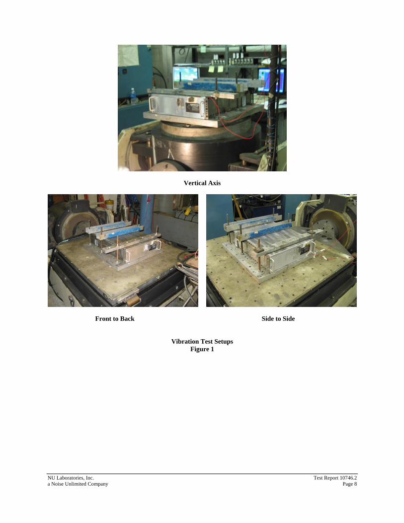
Upon receipt, a visual inspection of the Power Supply revealed no obvious physical damage or discrepancies. The Power Supply was clamped to an aluminum plate that was bolted to the vibration machine. Refer to Figure 1 for photographs of the vibration test setups. One (1) control accelerometer was attached to the fixture base plate and one (1) accelerometer was attached to the right side of the front cover of the Power Supply, oriented in the direction of vibration to aid in the detection of response prominences. The Power Supply was energized with 120 VAC with a minimal load throughout vibration testing.
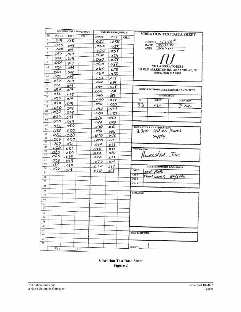
12.2 FIRST MAJOR AXIS OF VIBRATION (VERTICAL AXIS)
12.2.1 Exploratory Vibration The Power Supply was vibrated from 4 Hz through 33 Hz with a vibration input of 0.020 ± 0.004 inches (double amplitude) to determine response prominences. The change in frequency was made in discrete intervals of 1 Hz and the vibration was maintained at each frequency for approximately 15 seconds. No response prominences were noted. The table input vibration levels and the accelerometer output vibration levels at each frequency were recorded on the Vibration Test Data Sheet, Figure 2.
12.2.2 Variable Frequency Vibration The Power Supply was vibrated from 4 Hz through 33 Hz with input amplitudes as shown in Table 1. The change in frequency was made in discrete intervals of 1 Hz and the vibration was maintained at each frequency for a period of five (5) minutes. No response prominences were noted. The table input vibration levels and the accelerometer output vibration levels at each frequency were recorded on the Vibration Test Data Sheet.
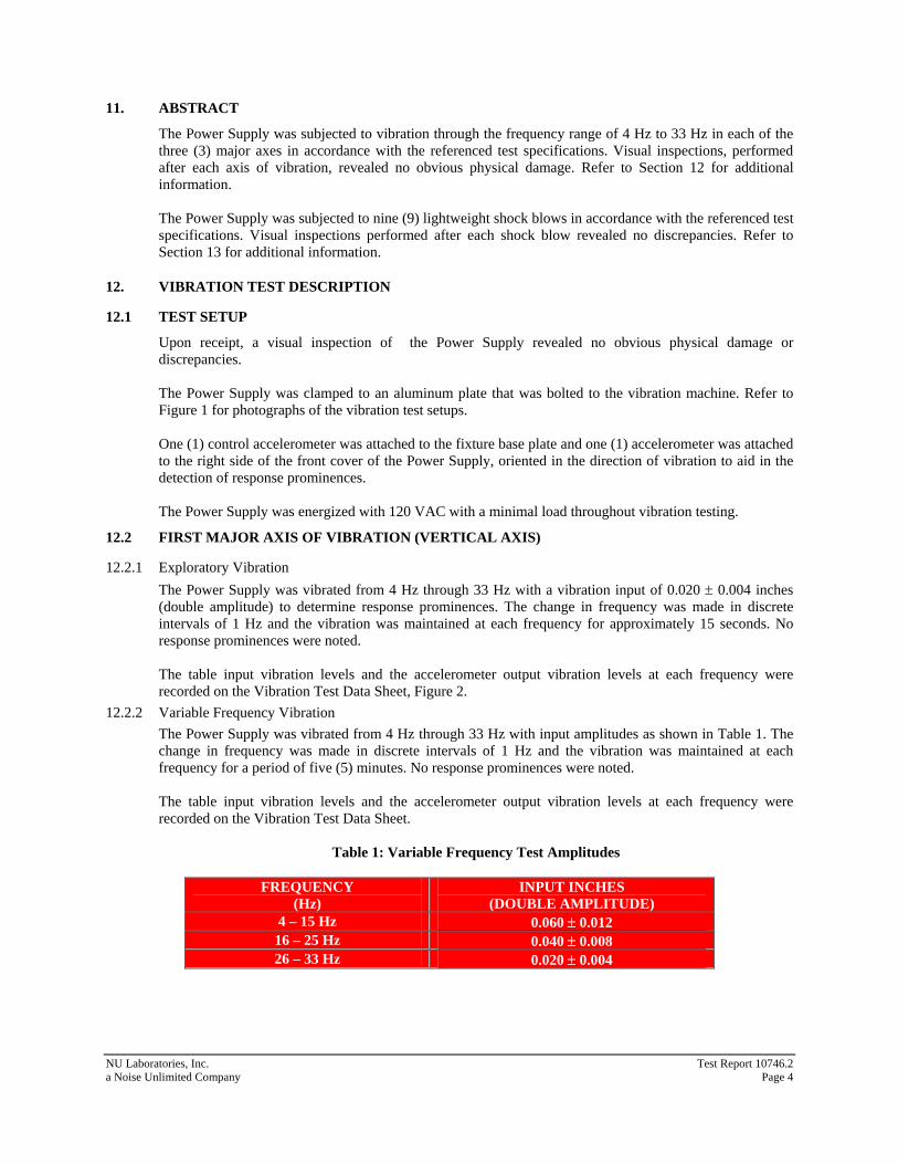
Table 1: Variable Frequency Test Amplitudes
FREQUENCY
(Hz) INPUT INCHES
(DOUBLE AMPLITUDE) 4 – 15 Hz 0.060 ± 0.012 16 – 25 Hz 0.040 ± 0.008 26 – 33 Hz 0.020 ± 0.004
NU Laboratories, Inc. Test Report 10746.2 a Noise Unlimited Company Page 5
12.2.3 Endurance Vibration Since no response prominences were noted, the Power Supply was subjected to endurance vibration testing at the specified upper frequency of 33 Hz for a period of two (2) hours. Upon completion of the two (2) hour dwell, a visual inspection of the Power Supply revealed no discrepancies.
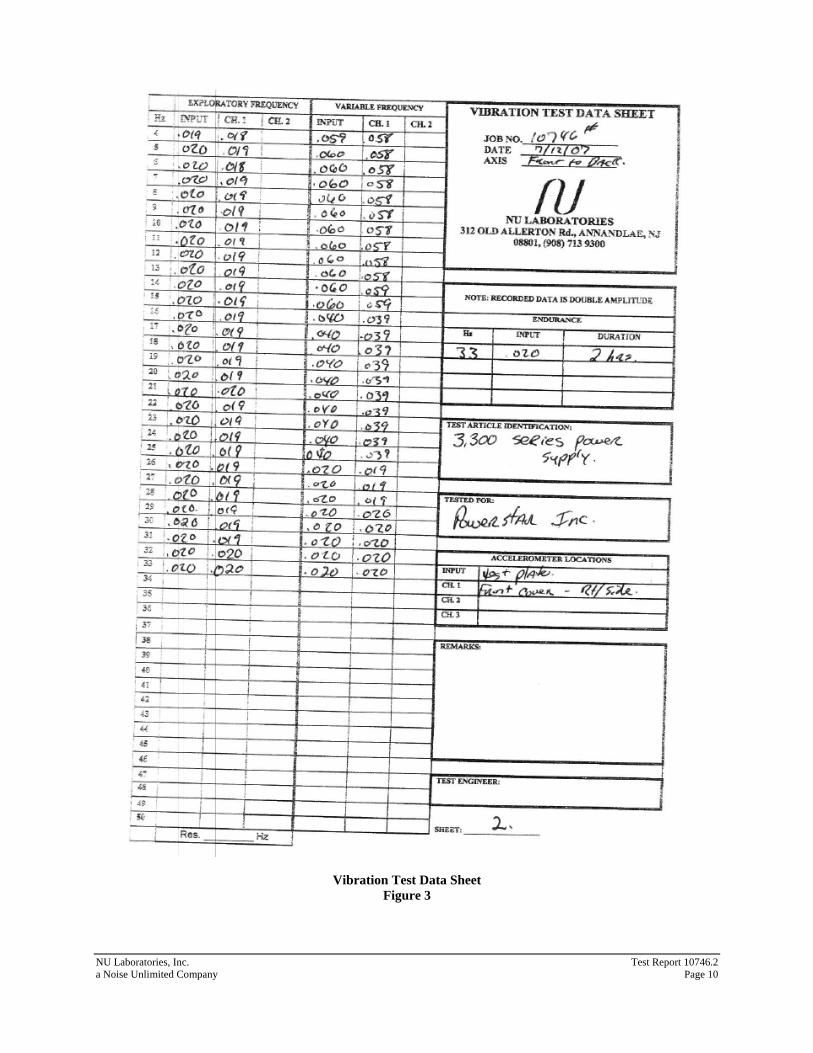
12.3 SECOND MAJOR AXIS OF VIBRATION (FRONT TO BACK)
12.3.1 Exploratory Vibration The Power Supply was vibrated from 4 Hz through 33 Hz with a vibration input of 0.020 ± 0.004 inches (double amplitude) to determine response prominences. The change in frequency was made in discrete intervals of 1 Hz and the vibration was maintained at each frequency for approximately 15 seconds. No response prominences were noted. The table input vibration levels and the accelerometer output vibration levels at each frequency were recorded on the Vibration Test Data Sheet, Figure 3.
12.3.2 Variable Frequency Vibration The Power Supply was vibrated from 4 Hz through 33 Hz with input amplitudes as shown in Table 1. The change in frequency was made in discrete intervals of 1 Hz and the vibration was maintained at each frequency for a period of five (5) minutes. No response prominences were noted. The table input vibration levels and the accelerometer output vibration levels at each frequency were recorded on the Vibration Test Data Sheet.
12.3.3 Endurance Vibration Since no response prominences were noted, the Power Supply was subjected to endurance vibration testing at the specified upper frequency of 33 Hz for a period of two (2) hours. Upon completion of the two (2) hour dwell, a visual inspection of the Power Supply revealed no discrepancies.
12.4 THIRD MAJOR AXIS OF VIBRATION (SIDE TO SIDE AXIS)
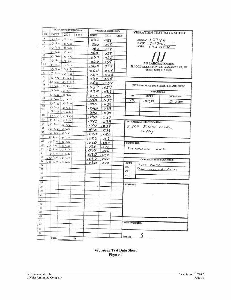
12.4.1 Exploratory Vibration The Power Supply was vibrated from 4 Hz through 33 Hz with a vibration input of 0.020 ± 0.004 inches (double amplitude) to determine response prominences. The change in frequency was made in discrete intervals of 1 Hz and the vibration was maintained at each frequency for approximately 15 seconds. No response prominences were noted. The table input vibration levels and the accelerometer output vibration levels at each frequency were recorded on the Vibration Test Data Sheet, Figure 4.
12.4.2 Variable Frequency Vibration The Power Supply was vibrated from 4 Hz through 33 Hz with input amplitudes as shown in Table 1. The change in frequency was made in discrete intervals of 1 Hz and the vibration was maintained at each frequency for a period of five (5) minutes. No response prominences were noted. The table input vibration levels and the accelerometer output vibration levels at each frequency were recorded on the Vibration Test Data Sheet.
12.4.3 Endurance Vibration Since no response prominences were noted, the Power Supply was subjected to endurance vibration testing at 33 Hz for a period of two (2) hours. Upon completion of the two (2) hour dwell, a visual inspection revealed no obvious physical damage. Refer to the Vibration Test Data Sheets, Figures 2 through 4, for additional information.
NU Laboratories, Inc. Test Report 10746.2 a Noise Unlimited Company Page 6
13. LIGHTWEIGHT SHOCK TEST DESCRIPTION
13.1 ACCEPTANCE CRITERIA
The Power Supply is considered to have successfully completed the lightweight shock test if no portion of the test item comes adrift or otherwise creates a hazard to personnel or other Grade A equipment.
13.2 TEST SETUP
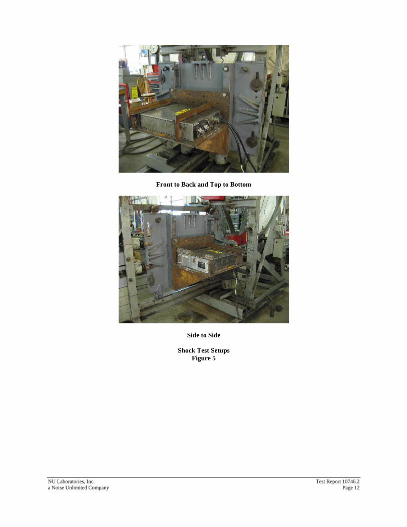
The Power Supply was bolted to an angle bracket using eight (8) ¼”-20 allen head Grade 8 screws torqued to 96 in-lbs. The entire assembly was secured to fixture Figure 4C of MIL-S-901D on the lightweight shock machine. Refer to Figure 5 for photographs of the test setups.
13.3 TEST CONDITIONS
The Power Supply was energized with 120 VAC with a 3 amp load throughout shock testing.
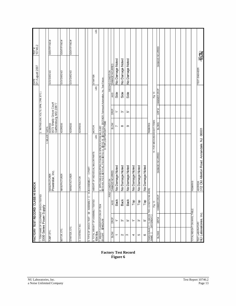
13.4 BLOW #1
13.4.1 Conditions: Front to Back, 1’ hammer height. 13.4.2 Observations: A post-blow visual inspection revealed no obvious physical damage. 13.4.3 Action: The mounting bolts were retorqued and testing was continued.
13.5 BLOW #2
13.5.1 Conditions: Front to Back, 3' hammer height. 13.5.2 Observations: A post-blow visual inspection revealed no obvious physical damage. 13.5.3 Action: Testing was continued.
13.6 BLOW #3
13.6.1 Conditions: Front to Back, 5’ hammer height. 13.6.2 Observations: A post-blow visual inspection revealed no obvious physical damage. 13.6.3 Action: Testing was continued.
13.7 BLOW #4
13.7.1 Conditions: Top to Bottom, 1’ hammer height. 13.7.2 Observations: A post-blow visual inspection revealed no obvious physical damage. 13.7.3 Action: Testing was continued.
13.8 BLOW #5
13.8.1 Conditions: Top to Bottom, 3' hammer height. 13.8.2 Observations: A post-blow visual inspection revealed no obvious physical damage. 13.8.3 Action: Testing was continued.
13.9 BLOW #6
13.9.1 Conditions: Top to Bottom, 5’ hammer height. 13.9.2 Observations: A post-blow visual inspection revealed no obvious physical damage. 13.9.3 Action: Testing was continued.
13.10 BLOW #7
13.10.1 Conditions: Side to Side, 1’ hammer height. 13.10.2 Observations: A post-blow visual inspection revealed no obvious physical damage. 13.10.3 Action: Testing was continued.
13.11 BLOW #8
13.11.1 Conditions: Side to Side, 3’ hammer height. 13.11.2 Observations: A post-blow visual inspection revealed no obvious physical damage. 13.11.3 Action: Testing was continued.
NU Laboratories, Inc. Test Report 10746.2 a Noise Unlimited Company Page 7
13.12 BLOW #9
13.12.1 Conditions: Side to Side, 5’ hammer height. 13.12.2 Observations: A post-blow visual inspection revealed no obvious physical damage. 13.12.3 Action: Testing was completed.
Refer to Figure 6, Factory Test Record, and Figure 7, Shock Acceptance Form, for additional information.
NU Laboratories, Inc. Test Report 10746.2 a Noise Unlimited Company Page 8
Vertical Axis
Front to Back Side to Side
Vibration Test Setups Figure 1
NU Laboratories, Inc. Test Report 10746.2 a Noise Unlimited Company Page 9
Vibration Test Data Sheet Figure 2
NU Laboratories, Inc. Test Report 10746.2 a Noise Unlimited Company Page 10
Vibration Test Data Sheet Figure 3
NU Laboratories, Inc. Test Report 10746.2 a Noise Unlimited Company Page 11
Vibration Test Data Sheet Figure 4
NU Laboratories, Inc. Test Report 10746.2 a Noise Unlimited Company Page 12
Front to Back and Top to Bottom
Side to Side
Shock Test Setups Figure 5
NU Laboratories, Inc. Test Report 10746.2 a Noise Unlimited Company Page 13
Factory Test Record Figure 6
NU Laboratories, Inc. Test Report 10746.2 a Noise Unlimited Company Page 14
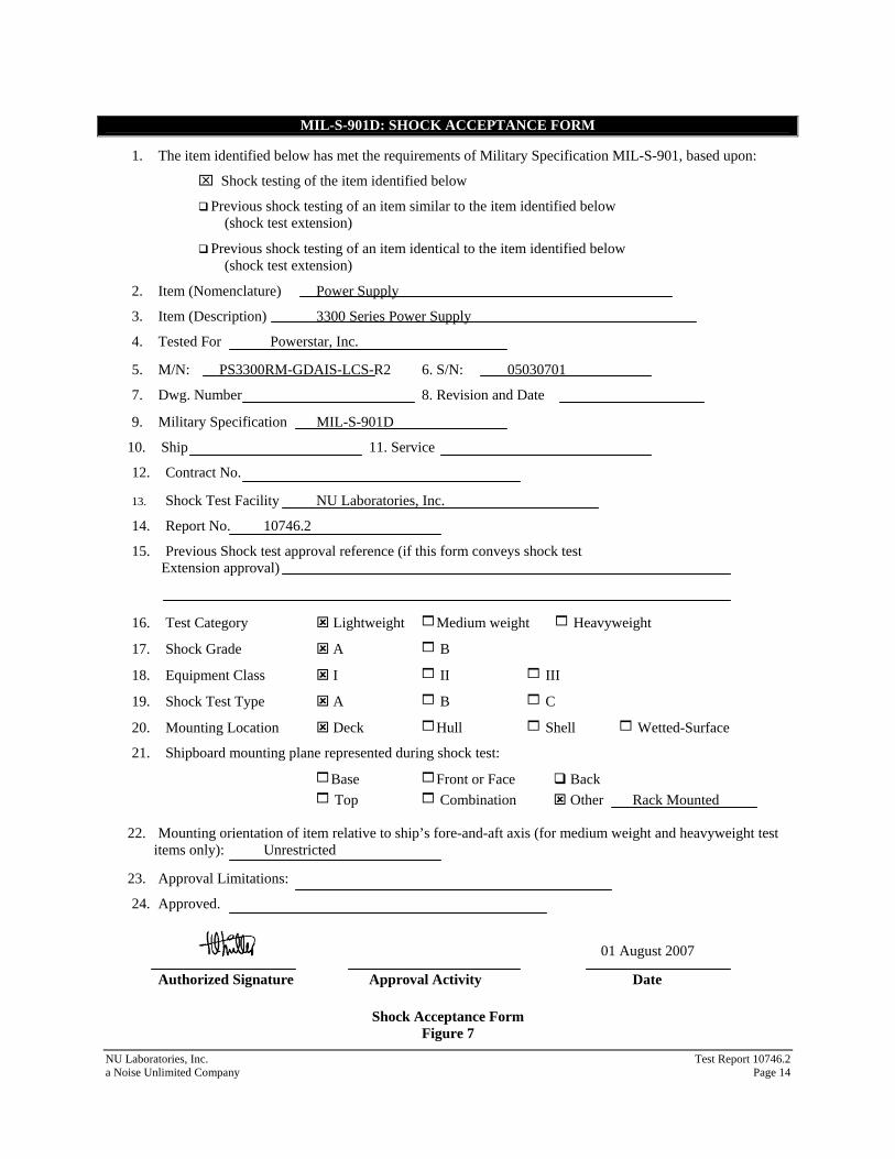
MIL-S-901D: SHOCK ACCEPTANCE FORM
1. The item identified below has met the requirements of Military Specification MIL-S-901, based upon:
⌧ Shock testing of the item identified below
Previous shock testing of an item similar to the item identified below (shock test extension)
Previous shock testing of an item identical to the item identified below (shock test extension)
2. Item (Nomenclature) Power Supply
3. Item (Description) 3300 Series Power Supply
4. Tested For Powerstar, Inc.
5. M/N: PS3300RM-GDAIS-LCS-R2 6. S/N: 05030701
7. Dwg. Number 8. Revision and Date
9. Military Specification MIL-S-901D
10. Ship 11. Service
12. Contract No.
13. Shock Test Facility NU Laboratories, Inc.
14. Report No. 10746.2
15. Previous Shock test approval reference (if this form conveys shock test Extension approval)
16. Test Category Lightweight 1Medium weight 1 Heavyweight
17. Shock Grade A 1 B
18. Equipment Class I 1 II 1 III
19. Shock Test Type A 1 B 1 C
20. Mounting Location Deck 1Hull 1 Shell 1 Wetted-Surface
21. Shipboard mounting plane represented during shock test:
1Base 1Front or Face Back 1 Top 1 Combination Other Rack Mounted
22. Mounting orientation of item relative to ship’s fore-and-aft axis (for medium weight and heavyweight test items only): Unrestricted
23. Approval Limitations:
24. Approved. 01 August 2007
Authorized Signature Approval Activity Date
Shock Acceptance Form Figure 7
NU Laboratories, Inc. Test Report 10746.2 a Noise Unlimited Company Page 15
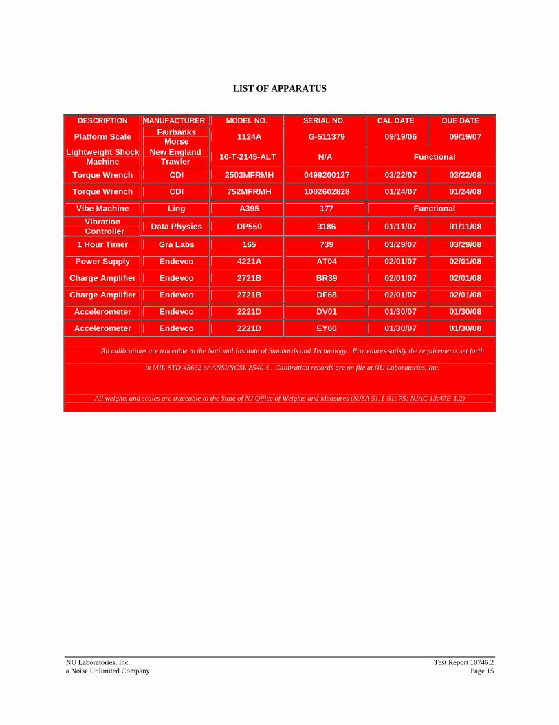
LIST OF APPARATUS
DESCRIPTION MANUFACTURER MODEL NO. SERIAL NO. CAL DATE DUE DATE
Platform Scale Fairbanks Morse 1124A G-511379 09/19/06 09/19/07
Lightweight Shock Machine
New England Trawler 10-T-2145-ALT N/A Functional
Torque Wrench CDI 2503MFRMH 0499200127 03/22/07 03/22/08
Torque Wrench CDI 752MFRMH 1002602828 01/24/07 01/24/08
Vibe Machine Ling A395 177 Functional Vibration Controller Data Physics DP550 3186 01/11/07 01/11/08
1 Hour Timer Gra Labs 165 739 03/29/07 03/29/08
Power Supply Endevco 4221A AT04 02/01/07 02/01/08
Charge Amplifier Endevco 2721B BR39 02/01/07 02/01/08
Charge Amplifier Endevco 2721B DF68 02/01/07 02/01/08
Accelerometer Endevco 2221D DV01 01/30/07 01/30/08
Accelerometer Endevco 2221D EY60 01/30/07 01/30/08
All calibrations are traceable to the National Institute of Standards and Technology. Procedures satisfy the requirements set forth
in MIL-STD-45662 or ANSI/NCSL Z540-1. Calibration records are on file at NU Laboratories, Inc.
All weights and scales are traceable to the State of NJ Office of Weights and Measures (NJSA 51:1-61; 75; NJAC 13:47E-1.2)