Embed Size (px)
Citation preview

Virtual Circuit Tree Multicasting: A Case for On-Chip Hardware MulticastSupport
‡Natalie Enright Jerger, ?Li-Shiuan Peh, and ‡Mikko Lipasti‡Electrical and Computer Engineering Department, University of Wisconsin-Madison
?Department of Electrical Engineering, Princeton University
AbstractCurrent state-of-the-art on-chip networks provide efficiency,
high throughput, and low latency for one-to-one (unicast)traffic. The presence of one-to-many (multicast) or one-to-all(broadcast) traffic can significantly degrade the performanceof these designs, since they rely on multiple unicasts to pro-vide one-to-many communication. This results in a burst ofpackets from a single source and is a very inefficient wayof performing multicast and broadcast communication. Thisinefficiency is compounded by the proliferation of architecturesand coherence protocols that require multicast and broadcastcommunication. In this paper, we characterize a wide array ofon-chip communication scenarios that benefit from hardwaremulticast support. We propose Virtual Circuit Tree Multicasting(VCTM) and present a detailed multicast router design thatimproves network performance by up to 90% while reducingnetwork activity (hence power) by up to 53%. Our VCTM routeris flexible enough to improve interconnect performance for abroad spectrum of multicasting scenarios, and achieves thesebenefits with straightforward and inexpensive extensions to astate-of-the-art packet-switched router.
1. IntroductionFuture many-core architectures with dozens to hundreds of
nodes will require scalable and efficient on-chip communicationsolutions [15]. This has motivated substantial research intonetwork-on-chip designs. Recent proposals [12], [14], [20],[21], [30] have successfully driven down interconnect delayto approach that of pure wire delay. However, one of theimplicit assumptions in the evaluation of these proposals isthat the vast majority of traffic is of a one-to-one (unicast)nature. Unfortunately, current router architectures are extremelyinefficient at handling multicast and broadcast traffic.
In this work, we leverage several popular research inno-vations to demonstrate that the assumption of predominantlyunicast traffic is not a valid one for on-chip networks andmotivate the design of our multicast router, Virtual CircuitTree Multicasting (VCTM). The inability of current routerarchitectures to efficiently handle multicast communication canalso have performance ramifications for unicast communica-tions. Unicast communications occurring at the same time as amulticast communication are likely to be delayed by the burstof communication.
This research was supported in part by the National Science Foundationunder grants CCR-0133437, CCF-0429854, CCF-0702272, CNS-0509402, theMARCO Gigascale Systems Research Center, an IBM PhD Fellowship, as wellas grants and equipment donations from IBM and Intel. The authors would liketo thank Niket Agarwal and Noel Eisley for their assistance with the tracesused in this study. Additionally, we thank the anonymous reviewers for theirthoughtful comments and constructive suggestions.
12
14
16
18
20
on
nec
t L
aten
cy
MC (10%)
MC (5%)
MC (1%)
6
8
10
0% 10% 20% 30% 40% 50%
Inte
rco
Network Load (% of Link Capacity)
( )
No MC
Figure 1. Performance of multicasts on packet-switchedinterconnect
Figure 1 shows the performance of a state-of-the-art packet-switched router in a 4x4 mesh in the presence of uniformrandom traffic. This router performs very well when all injectedpackets are intended for a single destination (No MC). Whenwe start injecting packets in the same cycle, at the same sourcedestined for multiple nodes, we see significant throughputdegradation; MC 1% converts 1% of injected packets into amulticast destined for a random number of destinations (<=15).If 1% of injected packets are multicasts the saturation pointdrops from 40% capacity to 25% capacity. Saturation is definedto be when the latency is double the zero-load latency. Thenetwork saturates at 20% and 5% for 5% and 10% multicastsrespectively. These multicast packets are broken down intomultiple unicasts by the network interface controllers as thepacket-switched routers are not designed to handle multipledestinations for one packet. More details about the packet-switched router under evaluation are discussed in Section 3.
Figure 2 shows a multicast originating from node X intendedfor nodes A, B, C and D. The network interface controllercreates four identical copies of the message (1A-1D). Withdeterministic dimension-ordered routing, all 4 messages wantto traverse the same link in the same cycle. Messages 1B and1D successfully arbitrate for the output in subsequent cycles.However, the messages now intended for nodes A and C areblocked waiting for B and D to gain access to a busy channel.Messages intended for B and D will again compete for the sameoutput port.
There are several problems in this scenario. The first issue isstalled messages 1A and 1C; this problem could be addressedwith more virtual channels and buffers at each router. Thesecond problem is competition for the same bandwidth; this canbe alleviated with wider links. Both of these solutions are costlyin terms of area and power and exhibit poor scalability. The
1D
1B
VCs
1C
1A
VCsX
A B
VCsBusy
VCs
1D1C
DC
VCs
Figure 2. Multiple unicast approach to multicasting
bandwidth bottleneck along the links could also be alleviatedthrough the use of an adaptive routing algorithm. However, thisdoes not address the fundamental inefficiency of the simultane-ous presence of multiple unnecessary messages in the network.In a network with moderate load or approaching saturation,these additional messages, even when spread out over disjointpaths, could drive up average network latency significantly. Theuse of multiple unicasts also causes additional congestion inthe network interface controller (NIC); the competition for theinjection port into the network can add significant delay topackets.
In addition to the performance inefficiencies, the multipleunicast approach to multicasting consumes additional power dueto redundant packets traversing the network. Power has becomea first-order design constraint for chip-multiprocessors. On-chipnetworks consume a significant fraction of total on-chip power[5], [42]; up to ∼ 30% for Intel’s 80-core teraflops network [15]and 36% for the RAW [39] on-chip network. Our VCTM routersubstantially reduces the power consumed by the network byeliminating the majority of these redundant packets (Section 5).
The design choices for the communication medium aretightly coupled with the communication characteristics of theapplication domain or the coherence protocol. When consider-ing future many-core architectures it would be unwise to designan interconnect without thought to the type of communicationthat will be most prevalent. Designs requiring multicast com-munication motivate the need for an efficient on-chip multicastrouter design. However, the absence of multicast routers foron-chip networks will hinder the deployment of protocols thatrequire this class of communication.
Several recent research proposals and industry trends lendthemselves to a multicast routing architecture. In some cases,such as architectures utilizing operand networks (e.g. RAW[39], TRIPS [31], Wavescalar [37]), they perform well withoutmulticasting but could be further enhanced with multicasting.Other designs such as broadcast coherence protocols experienceprohibitive latency without on-chip multicast support and areoften quickly dismissed as on-chip solutions. We outline thesescenarios below and will demonstrate the performance benefitsof multicasting in Section 5:
• Broadcast-based coherence protocols– Token Coherence: the TokenB protocol requires
broadcasting of tokens that maintain ordering amongstrequests [26].
– Intel’s next-generation QPI protocol: supports un-
ordered broadcasting between subsets of nodes [17].– AMD Opteron Protocol: order is maintained by com-
municating requests to an ordering point (memorycontroller) and then broadcasting from the orderingpoint [10].
– Uncorq [35]: unordered snoop delivery,• Multicast-based coherence protocols such as Multicast
Snooping [4] and Destination Set Prediction [28]• Invalidation requests in Directory Protocols
– Invalidation requests for widely shared data representthe primary need for multicasts.
• Operand delivery in scalar operand networks– Operands that are consumed by multiple instructions
could be multicast through the network.• New Innovations
– New coherence protocols, prefetching, and globalcache replacement policies are research areas thatcould benefit from the presence of on-chip hardwaremulticast support.
The above-mentioned multicasting scenarios will be exploredin greater depth in Section 2.
Multicasting support has been well researched for off-chipnetworks, particularly for multistage interconnection networks[25], [33], [36], [41]. Communications across off-chip networksare able to benefit from multicasting; the same is true for on-chip network communication. Several of the design trade-offsmade to realize off-chip multicasting are re-examined in thiswork. However, as power and area constraints for off- vs. on-chip routers differ substantially, prior off-chip multicast routerswhich require huge amounts of resources, such as large centralshared buffers [36] and high-port-count switches [41], are notsuitable for on-chip usage.
Virtual Circuit Tree Multicasting (VCTM) brings multicastfunctionality on chip without adding significant overhead to therouter pipeline. We employ a novel tree construction methodto ease routing complexity; tree construction occurs in parallelwith message delivery so our design avoids the setup latencyassociated with circuit-switching. With a modest amount of stor-age, the Virtual Circuit Table can hold the routing informationfor a large number of simultaneously active multicast trees.Our low-overhead design realizes substantial network latencysavings over current on-chip approaches (e.g. multiple unicasts).
In this work, we1) Characterize traffic for a variety of architectures and
motivate the need for hardware multicast support2) Explore the deficiencies of packet-switched routers for
mimicking multicast functionality3) Discuss off-chip multicasting mechanisms, their charac-
teristics that can be leveraged on-chip as well as down-sides that make them unsuitable for on-chip
4) Design an innovative on-chip multicast router that reducespower and improves performance for a variety of multi-casting scenarios.
2. Multicast MotivationSeveral recent research proposals could leverage hardware
multicast support to further enhance their performance. Inthis section, we will explore the opportunities within existing

proposals for multicasting. Beyond these scenarios, hardwaremulticast support will enable new research directions that wouldpreviously have suffered from poor interconnect performancedespite utilizing state-of-the-art on-chip network designs. Forall scenarios, we assume a tiled architecture connected via a4x4 (5x5 for TRIPs) 2D packet-switched mesh with 16-bytewide links (see Table 4).
2.1. Coherence ProtocolsIn general-purpose chip multiprocessors, the most natural
source of multicast traffic will be messages generated by thecoherence protocol. A wide variety of implemented and pro-posed coherence protocols will benefit from hardware multicastsupport.
2.1.1 Directory-based coherence. Directory-based protocolsare often chosen in scalable designs due to the point-to-pointnature of communication; however, they are not immune to one-to-many style communications. Directory protocols, such as theSGI-Origin Protocol [22], send out multiple invalidations froma single directory to nodes sharing a block; these invalidationscould leverage hardware multicast support. While not neces-sarily on the critical path, these requests can be frequent andcan waste power and hurt the performance of other networkrequests that are on the critical path.
Characterization of these invalidation messages in a full sys-tem simulation infrastructure [7] with a variety of commercialand scientific workloads [34], [40], [44] shows that invalidationmessages have an average network latency of up to 2 times theoverall average network latency. Table 1 shows the percentageof total requests that are invalidates.
2.1.2 Token Coherence. In broadcast-based protocols, ordering(for correctness) is often implicit through the use of a totally-ordered interconnect. To improve scalability, token coherenceremoves this implicit assumption and instead uses token countsto ensure proper ordering of coherence requests. A processormust hold at least 1 token to read a cache line and must holdall tokens to write to a cache line.
Broadcasting for these tokens can be a significant bottleneck.Originally intended as a chip-to-chip protocol with off-chipmulticast support, the absence of multicast functionality on-chip hurts the performance of token coherence and reduces itsattractiveness. Note that token coherence does not require allprocessors to respond to token requests, leading to fewer mes-sages as compared to the Intel QPI and Opteron-like protocols.
Figure 3 shows the slowdown of the TokenB protocol whenthe assumption of hardware multicast support is removed.GEMS 2.1 [27] was used to generate this data for a 16-coresystem. This release of GEMS include’s Princeton’s Garnet[2], a detailed network simulator which models link contentionand router microarchitectures. We used Garnet’s Flexible modeland modeled the router as a single-cycle pipeline with infinitebuffering. Despite the unrealistically aggressive router model,substantial slow down is already observed due to NIC and linkbandwidth bottlenecks.
2.1.3 Intel QPI Protocol. Intel’s new Quickpath Interconnect[17] will support unordered broadcasting among nodes. Aswith Token Coherence, ordering in QPI has been decoupledfrom the interconnect. Broadcasting has the potential to deliver
1.6
1.8
2
2.2
2.4
d E
xecu
tion
Tim
e
1
1.2
1.4
1.6
Barnes FFT FMM LU Ocean Radiosity
Norm
ali
zed
Figure 3. Token coherence slowdown in the absence ofhardware multicast support
shared data faster than a directory protocol by avoiding theindirection through the directory. However, as the number ofcoherent nodes in the system grows, the cost of broadcasting interms of delay, power and area becomes prohibitive. Hardwaremulticasting will lower the latency and power consumptionassociated with on-chip broadcasting.
2.1.4 AMD Opteron (HT) Protocol. AMD’s Opteron protocol[10] has been designed for maintaining coherence betweenchips in a traditional multiprocessor system. Coherence requestsare sent to a central ordering point (memory controllers) andthen broadcast to all nodes. The feasibility and potential formoving this style of protocol on-chip is directly tied to theperformance provided by the interconnect, and can be improvedwith multicasting. Recent research proposals have comparedthemselves to an on-chip Opteron-style protocol [35].
2.1.5 Recent Coherence Innovations. Evaluating the feasibil-ity of using the Opteron protocol on-chip also brings to light theissue of new coherence innovations that might be hampered ordiscarded due to the lack of on-chip multicast support. VirtualHierarchies [29] highlight a key characteristic of future systems;specifically in many-core CMPs, maintaining global coherenceamong all nodes will be very rare. The prohibitive cost ofglobal coherence will lead to a common case of maintainingcoherence among a limited subset of nodes. Virtual Hierarchiespropose two flavors of hierarchical coherence. The first is atwo level directory protocol and the second is a first levellocal directory protocol with a backing broadcast mechanismfor global coherence requests. Global broadcasts will likely berare in this scenario but will experience lower latency and powerby utilizing a multicast router.
An alternative protocol, one that broadcasts to a limitedsubset of nodes with a backing directory for global coherencewould benefit substantially from our proposed multicast router.We envision a region-based broadcast mechanism, which lever-ages Coarse-Grain Coherence Tracking [8], originally designedto avoid unnecessary broadcasts. This structure can be extendedto track nodes that are sharing within that region; a multicastcan then be used to enforce coherence of lines within thatregion. On a miss to a shared region, the processor multicaststhe coherence request to cores sharing that region. If there isno region information cached at the core, the miss request issent directly to the second level directory. The directory thenmulticasts the request to the region sharers and sends the sharinglist to the requestor. Broadcasting to this small subset of nodeswill provide better performance than a global broadcast or an

indirection through a directory.Maintaining global coherence among all nodes will be pro-
hibitive as many-core architectures scale to 100s of cores.Furthermore, certain classes of applications, such as serverconsolidation [13] will require only minimal global coherenceas virtual machines keep much of the address space private toa subset of cores. With a region-based multicast protocol, onlya limited subset of cores will need to be notified of coherencerequests within a given memory region.
Without efficient multicasting, these types of otherwisepromising coherence protocols become much less attractive.Considering the large number of cores that will be availablemoving forward, interconnect support for low latency one-to-many communication is critical. The tight coupling of on-chipresources mandates that interconnection network be designedwith communication behavior in mind and that coherenceprotocols be designed with interconnect capabilities in mind.Providing hardware multicasting support will facilitate signifi-cant innovations in on-chip coherence.
The following two scenarios represent more specialized ar-chitectures; however, operand networks and non-uniform cachesrepresent plausible and interesting solutions to the problems ofgrowing wire delay and scalability. We consider them here dueto their amenability to multicasting.
2.2. Operand Network Architectures and NUCACaches
Architectures such as TRIPS [31], RAW [39] and Wavescalar[37] use operand networks to communicate register valuesbetween producer and consumer instructions. The result of aninstruction is communicated to consumer tiles which then wakeup and fire instructions that are waiting on the new data. Ifthe result of one instruction is consumed by multiple subse-quent instructions on different tiles, operand delivery couldbe expediated by a multicast router. Studies have shown that35% of dynamic values generated by an application have 2or more future uses [6]. The cost of on-chip communicationcan significantly impact compiler decisions in this style ofarchitecture [19].
To mitigate increasing on-chip wire delays, non-uniformcache architectures (NUCA) have been proposed. DynamicNUCA [18] uses a packet-switched network and is furtheroptimized through the use of a multicast to quickly locatea block within a cache set. Recently, a multicast router hasbeen proposed to speed up this search operation and improveperformance [16].
2.3. CharacterizationOur evaluation in Section 5 will focus on a subset of the
above scenarios, namely directory coherence, TokenB, region-based coherence, the Opteron protocol and the TRIPs operandnetwork.
Table 1 and Figures 4 and 5 highlight some of the differentmulticast characteristics among these scenarios. In Figure 1, wedemonstrate that even a multicast rate of 1% is enough to causesignificant throughput degradation. Table 1 shows that all theabove scenarios exceed a multicast rate of 1% and will benefitfrom VCTM, our proposed hardware support for multicasting.
Despite the large potential number of unique multicastingcombinations, Figure 4 shows that there is significant reuse of
TABLE 1PERCENTAGE OF NETWORK REQUESTS THAT CAN BE MULTICAST
Scenario PercentageMulticast
Directory Protocols 5.1Token Coherence 5.5Region-Based Coherence 8.5Operand Networks (TRIPS) 12.4Opteron Protocol 3.1
a small percentage of multicasts. Multicast reuse is defined asmulticasts from the same source intended for the same destina-tion set. At one extreme, Token Coherence which uses one-to-allcommunication, has very few distinct multicast combinations.Multicasting for invalidations from a directory shows the leastreuse of destination sets for all the scenarios.
Figure 5 shows the breakdown of the number of nodes in eachmulticast destination set. Multicasts in Token Coherence andOpteron include all possible destinations. At the other extreme,the majority of multicasts in TRIPS are to only 2 nodes.Invalidations from the directory in the SGI Origin protocol goto only 2 nodes on average as well.
The bottom line is that architectures and protocols thatrequire multicast support have a variety of characteristics. Forexample, some protocols perform broadcasts to all nodes whileothers have relatively small destination sets. A robust multicastrouter design must be able to perform well under a wide varietyof conditions.
3. Network DesignVirtual Circuit Tree Multicasting builds on existing router
hardware in state-of-the-art networks, and augments it with alookup table that performs multicast route calculations. To sim-plify route construction, multicast trees are built incrementally,by observing the initial set of multiple unicasts and storing therouting information in the lookup table. This approach avoidsthe overhead of encoding multicast destination sets in the initialsetup message, and enables an efficient tree-ID based approachfor addressing multicast messages once the tree has been setup. As an additional benefit, conventional unicast traffic isunaffected by these straightforward additions to the networkrouter. Before we explain the details of our proposed VCTMrouter, we will discuss the highly optimized packet-switchedrouter used as a baseline in all our experiments.
40
50
60
70
80
90
100
ver
ag
e P
erce
nta
ge
TRIPS
Region
Directory
Token
Opteron
TRIPs Region
0
10
20
30
40
0 50 100 150
Mu
ltic
ast
Co
v
Number of Unique Destination Sets
D rectory
Opteron
TokenDirectory
Figure 4. Cumulate distribution of unique multicastdestination sets

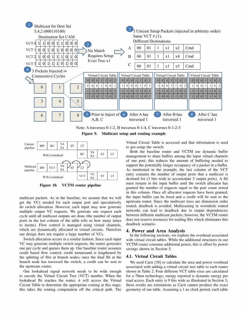
3.1. Packet-Switched RouterFigure 6a depicts a 4-stage router pipeline. The first stage is
the buffer write (BW); the routing computation (RC) occurs inthe second stage. In the third stage, virtual channel allocation(VA) and switch allocation (SA) are performed. In the presenceof low loads, speculation will be able to eliminate this stage. Instage 4, the flit traverses the switch (ST). Each pipeline stagetakes one cycle followed by one cycle to do the link traversal(LT) to the next router.
Recent work [14], [21] uses lookahead signals or advancedbundles to shorten the pipeline to a single stage. Our baselineleverages lookahead signals to reduce the pipeline to 2 stagesas depicted in Figure 6b. While the flit is traversing the switch,a lookahead signal is traveling to the next router to perform therouting computation. In the next cycle when the flit arrives, itwill proceed directly to switch allocation; resulting in a 2 cyclepipeline (VA/SA + ST).
The vast majority of current network-on-chip proposals ig-nore the issue of multicast communication. There are a fewexceptions which will be discussed further in Section 6. Pro-posals that might effectively leverage a multicast router eithernaively assume the existence of an on-chip multicast router orfail to model network contention (once contention is modeled,the need for hardware multicast support becomes abundantlyclear).
State-of-the-art packet-switched routers can of course utilizemultiple unicast messages to achieve multicast functionality.Decomposing a multicast into several unicasts can consumeadditional cycles and cause a bottleneck at the injection portas multiple messages try to access the network in the samecycle. In the baseline router, this injection bottleneck can addseveral cycles to the average network latency.
Many current router optimizations, such as speculative virtualchannel allocation, are effective only at low loads. Multipleunicasts drive up the network load, even if only briefly, andeasily render these optimizations ineffective. Several redundantmessages can be waiting in virtual channels for the same outputport (as illustrated in Figure 2).
Even in relatively small systems, on the order of 16 nodes,multiple unicasts can significantly degrade performance, asdemonstrated in Section 2. The poor performance of the mul-tiple unicast approach will be exacerbated by the presenceof more one-to-many or one-to-all communication as systemsgrows to encompass dozens or hundreds of nodes.
50%
60%
70%
80%
90%
100%
15-16
11-14
7-10
3 6
0%
10%
20%
30%
40%
TRIPS Region Directory Opteron Token
3-6
2
1
Figure 5. Percentage of nodes in each multicast destinationset size
BWVA
SAST LTRouter 1 RC
Router Link
(a) 4-Stage Packet-Switched Router Pipeline (with contention)
ST LTRouter 1
Router 2 (Lookahead)VA
SARC LTST
(b) Optimized PS Router w/ Lookahead (2 Stage)
Figure 6. Router pipeline
3.2. Virtual Circuit Tree MulticastingWith VCTM, each multicast first forms a virtual circuit
connecting the source with the destination set; identified bya VCT number unique to each source and destination setcombination. In a tree-based approach, a multicast continuesalong a common path and branches (replicates) the messagewhen necessary to achieve a minimal route to each destination.An alternative to tree-based routing is a path-based routing, e.g.the network first routes to the closest multicast destination, thenfrom there to the second nearest, and so on, rather than buildinga multicast tree connecting the destination set (see Section 6 formore details). Once a multicast tree has been set up, packets willbe routed based on this VCT number at each router. MultipleVCTs are time-multiplexed on physical links, as in conventionalvirtual circuit switching [11]. However, unlike virtual circuitswitching where intermediate routers do flow control based onvirtual circuits, and thus need to support all virtual circuits, weuse VCTs only for routing. Virtual channels are still used forflow control at the intermediate routers, with virtual channelsdynamically allocated to each virtual circuit at each hop.
The virtual circuit table is statically partitioned among sourcenodes; virtual circuit tree numbers are local to each source. Thevirtual circuit table is partitioned into n smaller tables eachneeding a Read/Write port for access from the source assignedthat partition. A table with 1024 VCT entries would allocate64 entries to each source node. In Section 5, we demonstratethat significant performance improvements can be achievedwith a much smaller number of virtual trees. Multicast treescan only be evicted at the source; this prevents any multicastpackets from missing in a downstream VCT table. Exploringthe benefits of dynamically partitioning the VCT table is left tofuture work.
Restricting the number of currently active VCTs requires thatthere be reuse of destination sets to see benefit. Data in Figure4 indicates that there is some amount of reuse across all ofour scenarios. The directory and region protocols have lessreuse than the other scenarios; however, this figure obscuresany temporal component of reuse. Even if a large number oftrees are touched across the entire execution, these scenariossee benefit from the temporal reuse of some multicast trees.
VCTM supports three different types of packets: normal

Head/
Body/Tail
MC/UC Id VCT #, Src
(Route)
UC
Dst
VC # Payload
(Command/Addr)
2 bits 2 bits 1 bit 10 bits 4 bits 3 bits
Fields
Width
Unicast
(Normal)
Unic st
00 - Head 00
Normal
x Route
Encoding
x0001 x001 Invalidate
x3000
00 H d 01 1 003 0001 001 I lid tUn cast
(Setup)00 - Head 01
Setup
1 x003 x0001 x001 Inval date
x3000
00 - Head 10
MC
1 x003 xxxx x001 Invalidate
x3000Multicast
Figure 7. Header packet encoding format, assuming 1024virtual circuits, 16 network nodes, and 8 virtual channels.
unicast, unicast+setup, and multicast. Normal unicast packetsare equivalent to those found in a traditional packet-switchedrouter, unicast+setup packets are sent to set up a multicast tree,and multicast packets are sent after multicast trees are set up.Figure 7 shows the different fields encoded in each type ofpacket. If the packet is a normal unicast, the lookahead routinginformation is encoded in the 4th field instead of the virtualcircuit tree number.
3.2.1 Router Microarchitecture. The router microarchitectureis shown in Figure 8. Normal Unicast packets traverse thehighly optimized pipeline shown in Figure 6; they do not needto access the Virtual Circuit Tree Table and are routed viaexisting hardware in the router pipeline (e.g. dimension-orderedrouting).
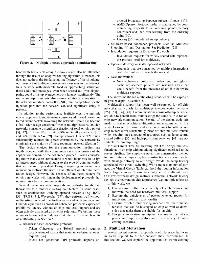
Routing a multicast packet can result in significant com-plexity; we avoid this complexity through the use of theunicast+setup packets to incrementally construct the trees.Unicast+setup packets deliver a packet payload to a singledestination node; however, while delivering this packet, theyalso add their destination to a multicast tree. The examplein Figure 9 walks through the process of constructing a newmulticast tree.
When the network interface controller at Node 0 initiatesa multicast message, it accesses a Destination Set CAM, con-taining all of its currently active multicast trees (Step 1). In thisexample, no matching entry is found, so the node will invalidateits oldest tree (say VCT 1) and begin establishing a new tree(Step 2).
Step 3 decomposes the multicast into one unicast packet perdestination. The packet type field is set to be unicast+setup, theId bit of former VCT 1 was 0 so the new Id bit is 1. Matching Idbits indicate that a new node is being added to an existing tree;
Src VCTnum
Virtual Circuit Tree Table
Switch Allocator
Virtual Channel Allocator
Output Ports
VC 0
Id Ej N S E W Fork
.
.
.
0 1 0 1 1 0 3
VC 0
MVC 0
VC 0
VC x
MVC 0
VC 0
VC x
MVC 0VC x
Input
Ports
Figure 8. Router microarchitecture
while differing Id bits indicate an old tree is being replaced witha new one. Each packet is given the same VCT number but adifferent destination. Additionally, all three packets contain thesame payload (i.e. memory address plus command).
In Step 4, each packet is injected into the network inconsecutive cycles. Unicast packets are dimension-order (X-Y)routed with respect to the source so the resulting multicast treewill also be dimension order routed.
The virtual circuit table updates at Node 1 are shown in Steps5-8. Step 5 shows the entries prior to the creation of new VCT1 (highlighted row 2 corresponds to VCT 1). Packet A is routedfirst. Upon arrival at Node 1, A determines that the VCT entry isstale (due to differing Id bits). Packet A will clear the previousbits in the row and then update the row with a 1 correspondingto its output port based on the routing computation performedby the unicast routing hardware; in this case, the East port. Thefinal column in the row is also updated to reflect the numberof output ports this multicast will be routed to.
At Step 7, the unicast destined for Node 4 will update theVCT entry. The Id bits are now the same, so it will not clear theinformation written by Packet A. A one will be stored into theSouth column and the output port count is updated to reflect anadditional output. Finally, Packet C traverses the link to Node1; Packet C will also use the East output port. Since PacketA already indicated that this multicast will use the East port,Packet C does not need to make any updates at Node 1.
Similar updates will be performed at each Virtual CircuitTable along the route. Updates to the Virtual Circuit Table donot impact the critical path through the router for normal unicastpackets as they do not perform any computation needed by theunicast packet to reach its destination.
When a subsequent multicast destined for 5, 4, and 2 arrivesat Node 0, it will find its destination set in the CAM. In thiscase, the node will form a multicast packet with VCT 1. Thevirtual circuit tree number will index into the Virtual CircuitTable at each router that will output the output ports that thispacket needs to be routed to. All three destinations of this packetshared a common route to Node 1 where the first fork occurs.After the first fork, one packet is routed to Node 4 and onepacket is routed to the East towards nodes 2 and 5. At Node 2,the packet forks again, with one packet being delivered to theejection port and another packet continuing on to Node 5.
We encode the destination set by using a virtual circuit treeidentifier. The virtual circuit tree identifier can be encodedwith log2(NumberofV irtualCircuitTrees) bits. This is amuch more scalable solution than the destination encoding usedin prior work while still allowing us the flexibilty to accessall destinations and have a variety of multicast tree activeconcurrently.
3.2.2 Router Pipeline. Figure 10 depicts the changes to therouter pipeline originally shown in Figure 6. Unicast packetsuse the original pipeline. VCTM makes only one change to therouter pipeline; for multicast packets the routing computationstage is replaced with the VCT table lookup. Additionally,VA/SA, ST and LT can occur multiple times if the packet isbranching at this node; if this is not a multicast branching node,then each of these stages executes once.
Speculative virtual channel allocation is still performed for
Multicast for Dest Set
5,4,2 (000110100)
1 1 0 0 1 1 0 0 0
0 0 1 0 1 0 0 0 0
1 0 0 1 1 1 0 1 0
1 0 1 1 1 0 1 0 0
Destination Set CAM
1
No Match
Requires Setup
Evict Tree x1
200 01 1 x1 x2 Cmd
3 Unicast Setup Packets (injected in arbitrary order)
Same VCT # (1),
Different Destinations
3
B
A
C
3 Packets Injected in
00 01 1 x1 x4 Cmd
00 01 1 x1 x5 Cmd4
VCT 0
VCT 1
VCT 2
VCT 3
0 1 2
3 4 5
6 7 8
3 P ckets I jected
Consecutive Cycles0 0 0 1 1 0 2
0 0 0 1 0 0 1
1 1 0 1 1 0 3
1 0 0 1 1 0 2
Virtual Circuit Table
5 Prior to Inject of
A,B, C
0 0 0 1 1 0 2
1 0 0 0 1 0 1
1 1 0 1 1 0 3
1 0 0 1 1 0 2
Virtual Circuit Table
6 After A has
traversed 1
0 0 0 1 1 0 2
1 0 0 1 1 0 2
1 1 0 1 1 0 3
1 0 0 1 1 0 2
7 After B has
traversed 1
Virtual Circuit Table
0 0 0 1 1 0 2
1 0 0 1 1 0 2
1 1 0 1 1 0 3
1 0 0 1 1 0 2
8 After C has
traversed 1
Virtual Circuit Table
Note: A traverses 0-1-2, B traverses 0-1-4, C traverses 0-1-2-5
Figure 9. Multicast setup and routing example
BWVA
SAST LT
Unicast
pipelineRC
VA
SAVCT LTST
VA
SAST LTVCTBWMulticast
pipeline
With Look he d
VA
SARC LTSTWith Lookahead
SAW th Lookahead
Figure 10. VCTM router pipeline
multicast packets. As in the baseline, we assume that we willget the VCs needed for each output port and speculativelydo switch allocation. However, each input may now generatemultiple output VC requests. We generate one request eachcycle until all multicast outputs are done (the number of outputports in the last column of the table tells us how many timesto iterate). Flow control is managed using virtual channels,which are dynamically allocated to virtual circuits. Thereforeour design does not require a large number of VCs.
Switch allocation occurs in a similar fashion. Since each inputVC may generate multiple switch requests, the router generatesone per cycle and queues them up. Our baseline router assumescredit based flow control; credit turnaround is lengthened bythe splitting of flits at branch nodes; once the final flit at thebranch node has traversed the switch, a credit can be sent tothe upstream router.
Our lookahead signal network needs to be wide enoughto encode the Virtual Circuit Tree (VCT) number. When thelookahead flit reaches the router, it will access the VirtualCircuit Table to determine the appropriate routing at this stage;this takes the routing computation off the critical path. The
Virtual Circuit Table is accessed and that information is usedto pre-setup the switch.
Both the baseline router and VCTM use dynamic buffermanagement to share buffers among the input virtual channelsof one port; this reduces the amount of buffering needed tosupport the potentially longer occupancy of a packet in a buffer.As mentioned in the example, the last column of the VCTentry contains the number of output ports that a multicast isdestined for (3 bits wide to accomodate 5 output ports). A flitmust remain in the input buffer until the switch allocator hasgranted the number of requests equal to the port count storedin this column. Once all allocator requests have been granted,the input buffer can be freed and a credit will be sent to theupstream router. Since the multicast trees are dimension orderrouted, deadlock is avoided. Multicasting in wormhole routednetworks can lead to deadlock due to output dependenciesbetween different multicast packets; however, the VCTM routerdoes not reserve resources for trailing flits which eliminates thisdeadlock scenario.
4. Power and Area AnalysisIn the following sections, we explore the overhead associated
with virtual circuit tables. While the additional structures in ourVCTM router consume additional power, this is offset by powersavings shown in Section 5.
4.1. Virtual Circuit TablesWe used Cacti [38] to calculate the area and power overhead
associated with adding a virtual circuit tree table to each routershown in Table 2. Four different VCT table sizes are calculatedfor a 70nm technology; energy reported is dynamic energy perread access. Each entry is 9 bits wide as illustrated in Section 3;these results are estimations as Cacti cannot produce the exactgeometry of our table. Assuming a 1 ns clock period, each table
can be accessed in less than half a cycle. In Section 5, we willdemonstrate that a small number of entries (512) is sufficient toachieve significant performance gains; the table size could bereduced further by using dynamic instead of static partitioningamong nodes; this is left to future work. Dynamic partitioningof the VCT tables would allow the approach to scale to a largernumber of nodes.
TABLE 2VCT TABLE OVERHEAD
Number of Area Energy Timeentries (mm
2) (nJ) (ns)512 0.024 0.0018 0.431024 0.041 0.0023 0.442048 0.078 0.0030 0.464096 0.101 0.0037 0.51
We also add a Destination Set CAM to each network interfacecontroller. This small CAM is searched for the VCT numbermatching the given destination set and can be overlapped withthe message construction and does not add additional latencyto the critical path. The NIC speculates that an active tree willbe found and inserts the VCT number returned by the CAMsearch. In the event of a misspeculation, it is reasonable toassume that decomposing a request into multiple unicast+setuppackets will take a couple of cycles, one per destination. EachCAM size in Table 3 corresponds to the number of VCT entriespartitioned evenly among 16 nodes. 32 to 64 entry CAMScan be accessed in under a cycle and will give each sourcea reasonable number of concurrent multicast trees. We do notforesee each core needing more trees as the system scales.
TABLE 3DESTINATION CAM OVERHEAD
Number of Area Energy Time Total Bytesentries (mm
2) (nJ) (ns) 16 nodes (25)32 0.018 0.007 0.87 64 (96)64 0.021 0.010 0.90 128 (192)128 0.029 0.017 1.09 256 (384)256 0.077 0.040 1.53 512 (768)
5. Evaluation5.1. Workloads Traces
To study a variety of architectures and coherence protocolswe leverage traffic traces collected from several simulation en-vironments. Traces for the directory and region-based protocolswere generated in PHARMsim [7], a full-system simulator.These traces are collected from end-to-end runs of 8 workloadsincluding 4 commercial workloads, SPECjbb, SPECweb, TPC-H and TPC-W and 4 scientific workloads from the Splash-2suite. To collect traces for Token Coherence and the Opteronprotocol, GEMS 2.1 with Garnet [2] full system simulationenvironment was used; each Splash-2 workloads was run forthe entire parallel phase. Finally, the TRIPs traces use SPEC[34] and MediaBench [1] workloads. They were run on aninstantiation of the Grid Processor Architecture containing anALU execution array and local L1 memory tiles connected viaa 5x5 network.
5.2. Synthetic TrafficIn addition to traffic from real workloads, we utilize synthetic
traffic to further stress our router design. With a uniform random
20
40
60
80
100
120
orm
ali
zed
Usa
ge
16
0
20
Lin
k
Buff
er
Cro
ssb
ar
Lin
k
Buff
er
Cro
ssb
ar
Lin
k
Buff
er
Cro
ssb
ar
Lin
k
Buff
er
Cro
ssb
ar
Lin
k
Buff
er
Cro
ssb
ar
Directory TokenB Region TRIPs Opteron
No
4096
Figure 11. Reduction in buffering, link and crossbartraversals
traffic generator, we can adjust the network load as well asthe percentage of multicasts. This traffic generator was used tocollect the data in Figure 1.
5.3. Network ConfigurationIn the next sections, we present the improvement in network
latency observed with VCTM relative to our baseline packet-switched network with no multicast support for each outlinedscenario. In each graph, 0 Virtual Circuit Trees correspondsto the baseline network where a multicast is decomposed intomultiple unicasts. We vary the size of the Virtual Circuit Treetable along the x-axis in Figures 12-16. The network parametersare given in Table 4.
TABLE 4NETWORK & VIRTUAL CHANNEL ROUTER PARAMETERS
Topology 4-ary 2-mesh5-ary 2-mesh TRIPS
Routing X-Y RoutingChannel Width 16 BytesPacket Size 1 flit (Coherence req Addr+Cmd)
5 flits (Data)3 flits (TRIPs)
Virtual Channels 4Buffers per port 24Router ports 5VCTs Varied from 16 to 4K
(1 to 256 VCTs/core)
5.4. Power SavingsThe virtual circuit table increases the power consumption of
our multicast router over the baseline packet-switched router;however, this increase in power consumption is offset byreducing redundant link switching and buffering.
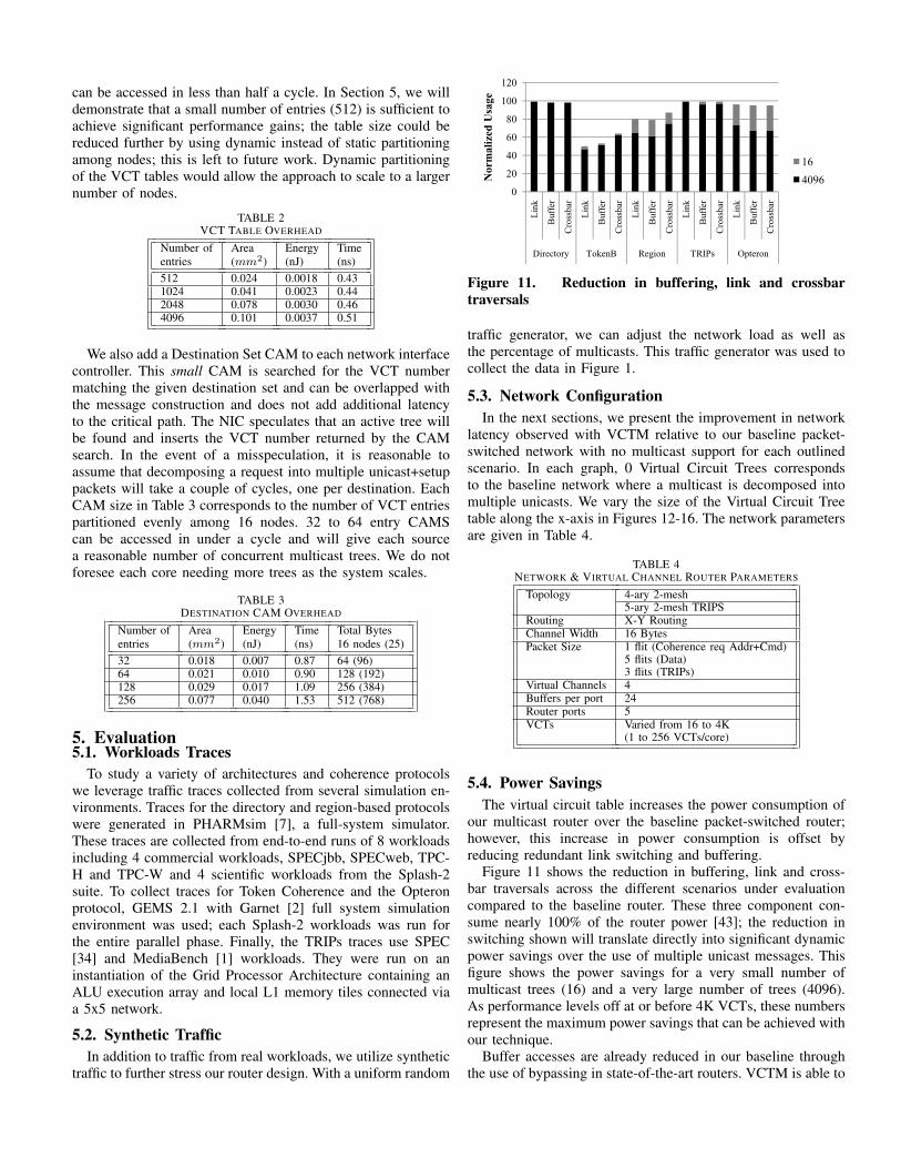
Figure 11 shows the reduction in buffering, link and cross-bar traversals across the different scenarios under evaluationcompared to the baseline router. These three component con-sume nearly 100% of the router power [43]; the reduction inswitching shown will translate directly into significant dynamicpower savings over the use of multiple unicast messages. Thisfigure shows the power savings for a very small number ofmulticast trees (16) and a very large number of trees (4096).As performance levels off at or before 4K VCTs, these numbersrepresent the maximum power savings that can be achieved withour technique.
Buffer accesses are already reduced in our baseline throughthe use of bypassing in state-of-the-art routers. VCTM is able to

1
1.05con
nect
Late
ncy
specJBB
specWEB
0.85
0.9
0.95
0 16 32 64 128 512 2048 4096
No
rma
lize
d I
nte
rc
Number of Virtual Circuit Trees
TPC-H
Barnes
Ocean
Radiosity
Raytrace
Figure 12. SGI-Origin Directory Protocol network perfor-mance
further reduce overall accessed by removing redundant packetsfrom the network. Removing redundant packets allows morepackets to bypass input buffers than in the base case.
Virtual Circuit Trees are constructed along X-Y routing paths.The use of X-Y routing results in deadlock free tree formations;however, X-Y routing does not necessarily produce optimaltrees. All destinations are routed to in a minimal fashion butalternative routing algorithms may produce trees that utilizefewer links to reach those destinations. To determine howclose to optimal our trees are, we remove the X-Y routingrestriction; as a result minimum spanning trees can be foundthat use up to 60% fewer links; however, the overall savingsacross all multicasts is only 2%. Despite this large possiblereduction, the average reduction in link traversals is less than1% when compared to the saving achieved with X-Y routing.As a result, the power savings detailed in Figure 11 are closeto the maximum possible savings.
5.5. Performance EvaluationAs mentioned earlier, the potential performance improvement
come from two main factors, reduction in network load (im-proved throughput) and reduced contention for network injec-tion ports. The VCTM router reduces the number of messagesinjected into the network from the size of the destination setto a single message. Injection port contention accounts forup to 35% of packet latency in the baseline. On average,alleviating injection pressure reduces the cycles spent in thenetwork interface by 0.2 (directory), 6 (token), 5 (region), 0.5(TRIPs) and 3.5 (Opteron) cycles.
5.5.1 Coherence Protocols. For the directory protocol wesimulate 32KB L1 caches and private 1MB L2 caches. Ad-dresses are distributed across 16 directories, with one directorylocated at each processor tile. The reduction in network latencyfor a directory protocol is shown in Figure 12. Invalidationrequests represent approximately 5% of network requests forthe directory protocol. However, since the network load for thisprotocol is low for applications like specJBB, TPC-H, Raytraceand Ocean, VCTM is unable to realize substantial benefits.SPECweb has a slightly higher load which translates into morebenefit from VCTM (up to 12%).
Token coherence simulations were configured with 64 KBL1 caches and 1 MB private L2 caches with a MOESI TokenBprotocol. Normalized interconnect latency is presented in Figure
0.6
0.8
1
1.2
Inte
rcon
nec
t L
ate
ncy
Barnes
FFT
FMM
LU
Ocean
Radiosity
0
0.2
0.4
0 16 32 64 128 512
No
rma
lize
d I
Number of Virtual Circuit Multicast Trees
y
Figure 13. TokenB network performance with VCTM
13. To request tokens, the source node broadcasts to all othernodes on-chip; as a result, only one virtual circuit multicast treeis needed per node. If the source node sent out a multicast witha variable destination set, a VCT count larger than 16 wouldbe useful. Radiosity has reached network saturation with thebaseline configuration; relieving the pressure caused by multipleunicasts results in substantial latency improvement of close to100%. Barnes and LU are also very close to saturation, leadingto close to 90% savings in latency.
We further evaluate VCTM using path-based multicast rout-ing rather than tree-based multicasting. For workloads near orat saturation, a path-based multicast can also effectively relievenetwork pressure and reduce latency by an average of 70%;however, for workloads not nearing saturation (FFT, FMM,and Ocean), the path-based multicast increases network latencyby 48% over the baseline. For more discussion on path-basedrouting trade-offs see Section 6.
The region-based coherence protocol uses 2KB regions; eachregion covers 32 cache lines. Region coherence arrays (RCA)are used to store the sharing list for each 2KB region; theseRCAs sit alongside the L2 cache. The 16-core configurationused to generate these traces consists of 32 KB L1 cachesand a private 1MB L2 cache per core. Figure 14 presents theimprovement in network latency for this region-based scheme.This coherence protocol needs more simultaneous multicasttrees than the other scenarios to see substantial benefit. Thedestination sets used by the region protocol vary much morewidely; however, the overhead of supporting additional treesis low, 512 or 2048 VCTs would be a feasible design andwould reduce network latency by up to 65%. Without multicastsupport, this type of coherence protocol would see prohibitivenetwork latency for sending out snoop requests.
Figure 15 shows benchmarks with varying degrees of im-provement due to multicast support for the TRIPs architecture.Art sees the most benefit due to the network load approachingsaturation and a significant reduction in the number of packetsby using VCTM. The majority of workloads see up to 20%improvement due to the low number of nodes in the destinationset (average 2). Additionally, many of the multicast treesconstructed for this workload branch at the source node. If thebranch occurs at the source node, no benefit is seen as there willbe no reduction in packets over the multiple unicast baselineapproach. Path-based multicasting outperforms VCTM for art,

0.6
0.7
0.8
0.9
1
1.1
Inte
rco
nn
ect
La
ten
cyspecJBB
specWEB
TPC-H
TPC-W
Barnes
0.2
0.3
0.4
0.5
0 16 32 64 128 512 2048 4096
No
rma
lize
d I
Number of Virtual Multicast Circuit Trees
Ocean
Radiosity
Raytrace
Figure 14. Region Coherence network performance withVCTM
0.7
0.8
0.9
1
1.1
ized
In
terc
on
nec
t
La
ten
cy
adpcm
ammp
art
bzip2
compress
dct
equake
0.4
0.5
0.6
0 16 32 64 128 512 2048 4096
No
rmali
# of Virtual Multicast Trees
gzip
mcf
mgrid
parser
swim
tomcatv
Figure 15. TRIPs network performance with VCTM
bzip2, and swim by 4% here due to more effectively reducingthe network load.
Traces were generated for the Opteron protocol with 64 KBL1 caches and a 16 MB fully shared L2 cache. The Opteronprotocol sees steady improvement with the addition of VirtualCircuit Trees; once 512 VCTs are available, performance levelsoff with a savings of 47% in network latency. Some filtering ofdestinations occurs in this protocol resulting in a larger numberof trees than the TokenB protocol. In all cases, path-based mul-ticasting performs worse than the baseline and VCTM. Nearlyall multicasts in the Opteron protocol go to 15 destinations soa path-based multicast has to snake through the chip to eachnode; if a non-optimal path is chosen, latency will be high. Anadditional downside to path-based multicasting, not reflectedin the network latency is that the requestor will have to waituntil the last node in the path has received and responded tothe snoop. VCTM delivers all snoops in a more timely fashionresulting in faster snoop response.
For VCT tables with 512 entries, we are able to achievesignificant reuse across all scenarios. Average VCT table hitrates range from 62% to 99%; with directory coherence seeingthe lowest hit rates overall.
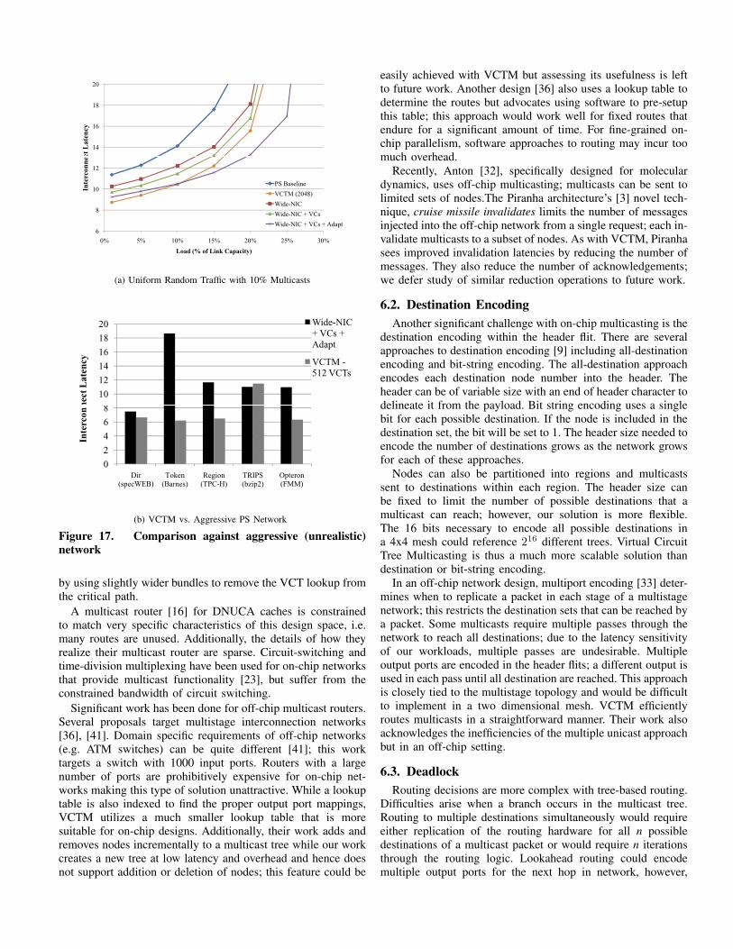
5.5.2 Synthetic Traffic. Several aggressive packet-switchednetworks are evaluated in Figure 17a for their ability to ap-proach the performance of VCTM. The PS baseline representsthe same baseline configuration used above. The network inter-face (NIC) represents a substantial bottleneck for multicasting,so the Wide-NIC configuration allows the NIC to inject as manypackets as are waiting in a cycle (in the baseline only onepacket can be accepted per cycle). We add to Wide-NIC nearlyinfinite Virtual Channels and buffers (wide-nic+vcs). To better
0.8
0.9
1
1.1
lize
d I
nte
rcon
nec
t
Late
ncy
Barnes
FFT
FMM
Ocean
0.5
0.6
0.7
0 16 32 64 128 512 2048 4096
Norm
al
Number of VCTs
Figure 16. Opteron Protocol
distribute the network load, we utilize adaptive routing (wide-nic+vcs+adapt). Finally, we compare each of these scenariosto VCTM with 2048 VCTs. Here, approximately half of thelatency penalty associated with the multiple unicast approach ispaid in the NIC; creating a wider issue NIC would likely resultin significant overhead and complexity; more so than our pro-posal. Wide-NIC+VCs+Adapt outperforms VCTM for moderateloads; performance improvements in VCTM are predicatedon tree reuse which is very low for uniform random traffic.Building a design with a very large number of VCs wouldhave a prohibitive cost (area and power); we believe our designis much more practical. Figure 17b illustrates that with realworkloads, VCTM outperforms a highly aggressive (unrealistic)packet-switched router. We compare one benchmark runningwith 512 VCTs from each scenario to Wide-NIC+VCs+Adapt.
6. Related WorkIn this section, we differentiate VCTM from prior proposals
along three axes: routing, destination encoding and deadlock.
6.1. RoutingThere are two techniques for routing multicast messages:
path-based routing and tree-based routing. In path-based rout-ing, each destination is visited sequentially until the last node isreached. Paths must be carefully selected to avoid a deadlock;cycles can occur in the network even in the presence ofdimension order routing. Path-based multicasting also has theadded complexity of finding the shortest path that visits allnodes in the destination set.
Very little prior work focuses on the design of on-chipmulticast routers. In [24], the authors construct circuits formulticasting in a wormhole network. Path-based routing plusthe requirement of setup and acknowledgement messages resultsin a long latency overhead for their approach. Alternatively, wefocus on a tree-based multicast routing in this work but alsocompare against path-based multicasting.
With a path-based multicast, current lookahead routing mech-anisms can be used as only one destination is being routedto at a time. Path multicasting is attractive for its simplicity;implementing a path multicast would require only minor modi-fications to the current packet-switched router. Recent work hasshown network latency to be a critical factor for commercialworkloads on CMPs [12]; therefore, it is preferable to avoidthe sequential latency associated with a path-based routingapproach. Our design is able to leverage lookahead techniques
14
16
18
20ct
La
ten
cy
6
8
10
12
0% 5% 10% 15% 20% 25% 30%
Inte
rcon
nec
Load (% of Link Capacity)
PS Baseline
VCTM (2048)
Wide-NIC
Wide-NIC + VCs
Wide-NIC + VCs + Adapt
(a) Uniform Random Traffic with 10% Multicasts
8
10
12
14
16
18
20
nect
La
ten
cy
Wide-NIC
+ VCs +
Adapt
VCTM -
512 VCTs
0
2
4
6
8
Dir
(specWEB)
Token
(Barnes)
Region
(TPC-H)
TRIPS
(bzip2)
Opteron
(FMM)
Inte
rco
n
(b) VCTM vs. Aggressive PS Network
Figure 17. Comparison against aggressive (unrealistic)network
by using slightly wider bundles to remove the VCT lookup fromthe critical path.
A multicast router [16] for DNUCA caches is constrainedto match very specific characteristics of this design space, i.e.many routes are unused. Additionally, the details of how theyrealize their multicast router are sparse. Circuit-switching andtime-division multiplexing have been used for on-chip networksthat provide multicast functionality [23], but suffer from theconstrained bandwidth of circuit switching.
Significant work has been done for off-chip multicast routers.Several proposals target multistage interconnection networks[36], [41]. Domain specific requirements of off-chip networks(e.g. ATM switches) can be quite different [41]; this worktargets a switch with 1000 input ports. Routers with a largenumber of ports are prohibitively expensive for on-chip net-works making this type of solution unattractive. While a lookuptable is also indexed to find the proper output port mappings,VCTM utilizes a much smaller lookup table that is moresuitable for on-chip designs. Additionally, their work adds andremoves nodes incrementally to a multicast tree while our workcreates a new tree at low latency and overhead and hence doesnot support addition or deletion of nodes; this feature could be
easily achieved with VCTM but assessing its usefulness is leftto future work. Another design [36] also uses a lookup table todetermine the routes but advocates using software to pre-setupthis table; this approach would work well for fixed routes thatendure for a significant amount of time. For fine-grained on-chip parallelism, software approaches to routing may incur toomuch overhead.
Recently, Anton [32], specifically designed for moleculardynamics, uses off-chip multicasting; multicasts can be sent tolimited sets of nodes.The Piranha architecture’s [3] novel tech-nique, cruise missile invalidates limits the number of messagesinjected into the off-chip network from a single request; each in-validate multicasts to a subset of nodes. As with VCTM, Piranhasees improved invalidation latencies by reducing the number ofmessages. They also reduce the number of acknowledgements;we defer study of similar reduction operations to future work.
6.2. Destination EncodingAnother significant challenge with on-chip multicasting is the
destination encoding within the header flit. There are severalapproaches to destination encoding [9] including all-destinationencoding and bit-string encoding. The all-destination approachencodes each destination node number into the header. Theheader can be of variable size with an end of header character todelineate it from the payload. Bit string encoding uses a singlebit for each possible destination. If the node is included in thedestination set, the bit will be set to 1. The header size needed toencode the number of destinations grows as the network growsfor each of these approaches.
Nodes can also be partitioned into regions and multicastssent to destinations within each region. The header size canbe fixed to limit the number of possible destinations that amulticast can reach; however, our solution is more flexible.The 16 bits necessary to encode all possible destinations ina 4x4 mesh could reference 216 different trees. Virtual CircuitTree Multicasting is thus a much more scalable solution thandestination or bit-string encoding.
In an off-chip network design, multiport encoding [33] deter-mines when to replicate a packet in each stage of a multistagenetwork; this restricts the destination sets that can be reached bya packet. Some multicasts require multiple passes through thenetwork to reach all destinations; due to the latency sensitivityof our workloads, multiple passes are undesirable. Multipleoutput ports are encoded in the header flits; a different output isused in each pass until all destination are reached. This approachis closely tied to the multistage topology and would be difficultto implement in a two dimensional mesh. VCTM efficientlyroutes multicasts in a straightforward manner. Their work alsoacknowledges the inefficiencies of the multiple unicast approachbut in an off-chip setting.
6.3. DeadlockRouting decisions are more complex with tree-based routing.
Difficulties arise when a branch occurs in the multicast tree.Routing to multiple destinations simultaneously would requireeither replication of the routing hardware for all n possibledestinations of a multicast packet or would require n iterationsthrough the routing logic. Lookahead routing could encodemultiple output ports for the next hop in network, however,

the destination set would need to be properly partitioned. Ata fork, a subset of destinations would need to be encoded ineach branch. Failing to prune destinations from the header flitor improperly pruning destinations would result in deadlock.VCTM uses the VCT number to avoid the partitioning andpruning the destination set.
Research into deadlock-free multicast tree routing [25] usespruning to prevent deadlock in a wormhole-routed network.Their work targets small messages such as invalidates in a DSMsystem. In VCTM, for a given tree, all of the leaf destinationsare reached via dimension-order routing with respect to thesource node; therefore no cycles can occur within a singlemulticast tree instance. If a tree were allowed to adaptivelyroute with respect to a branch (an intermediate route point)deadlock would be a problem.
We evaluate VCTM with proposals that represent a range ofscenarios; however we believe VCTM is widely amenable toother proposals mentioned in Sections 1 and 2. For example, ifdestination sets exhibit temporal reuse, VCTM will work wellwith Destination Set Prediction [28].
7. ConclusionIn this paper, we present a case for hardware support for
on-chip multicasting. Our characterization of existing networkapplications (directory coherence, Opteron coherence protocol)as well as proposed future applications (Token Coherence,TRIPS, Region coherence) strongly supports our claim thatmulticasting is both necessary and useful. Furthermore, theavailability of efficient support for on-chip multicasting willmost likely enable future techniques that may otherwise appearunattractive or even infeasible.
In support of these existing and proposed applications, wedescribe a novel on-chip multicast router that fills a significantgap in the design space. We believe VCTM is the first multicastrouter for a general-purpose CMP design with the flexibilityto provide superior performance across a variety of scenarios;future work will explore additional novel scenarios that aremade possible through our VCTM router.
Our VCTM design substantially reduces power consumptionover state-of-the-art designs that do not directly support mul-ticasting. On average we see a 29%, 22% and 20% reductionin link switching, buffer and crossbar power respectively; witha maximum savings of 53%, 49% and 38%. Virtual CircuitTree Multicasting is also able to reduce network latency byup to 90% with an average latency reduction of 39%. Eventhough many of our scenarios are not operating at saturation,we see significant benefits through improved speculation fromthis reduction. Network latency-throughput is a critical factorfor many applications; this significant reduction will not onlybenefit existing applications and architectures but also pave theway for new coherence protocol innovations.
References[1] http://www.eecs.umich.edu/mibench.[2] http://www.princeton.edu/ niketa/garnet.html, 2008.[3] L. A. Barroso, et al., “Piranha: A scalable architecture based on single-
chip multiprocessing,” in ISCA-27, 2000.[4] E. Bilir et. al, “Multicast snooping: A new coherence method using a
multicast address network,” in ISCA-26, 1999.[5] S. Borkar, “Networks for multi-core chips: A contrarian view,” Special
Session at ISLPED 2007.[6] J. A. Butts and G. Sohi, “Characterizing and predicting value degree of
use,” in MICRO-35, 2002.
[7] H. Cain, K. Lepak, B. Schwarz, and M. H. Lipasti, “Precise and accurateprocessor simulation,” in Workshop On Computer Architecture Evaluationusing Commercial Workloads, 2002.
[8] J. F. Cantin, M. H. Lipasti, and J. E. Smith, “Improving multiprocessorperformance with coarse-grain coherence tracking,” in ISCA-32, 2005.
[9] C. Chiang and L. Ni, “Multi-address encoding for multicast,” in Proc. ofthe Workshop on Parallel Comp. Routing and Communication, 1994.
[10] P. Conway and B. Hughes, “The AMD Opteron Northbridge architecture,present and future,” IEEE Micro Mag., Apr. 2007.
[11] W. Dally and B. Towles, Principles and Practices of InterconnectionNetworks. Morgan Kaufmann Pub., 2003.
[12] N. Enright Jerger, , L.-S. Peh, and M. Lipasti, “Circuit-switched coher-ence,” in IEEE 2nd Network on Chip Symposium, 2008.
[13] N. Enright Jerger, D. Vantrease, and M. H. Lipasti, “An evaluationof server consolidation workloads for multi-core designs,” in IEEE ofSymposium on Workload Characterization, 2007.
[14] P. Gratz et. al, “Implementation and evaluation of on-chip networkarchitectures,” in ICCD, 2006.
[15] Intel, “From a few cores to many: A Tera-scale computing research overview,” 2006. [Online].Available: http://download.intel.com/research/platform/terascale/ teras-cale overview paper.pdf
[16] Y. Jin, E. J. Kim, and K. H. Yum, “A domain-specific on-chip networkdesign for large scale cache systems,” in HPCA, 2007.
[17] D. Kanter, “The common system interface: Intel’s future interconnect,”http://www.realworldtech.com/page.cfm? ArticleID=RWT082807020032,2007.
[18] C. Kim, D. Burger, and S. W. Keckler, “An adaptive, non- uniform cachestructure for wire- delay dominated on-chip caches,” in Proceedings ofASPLOS, 2002.
[19] M. M. Kim, S. Swanson, A. Peterson, A. Putnam, A. Schwerin, M. Oskin,and S. Eggers, “Instruction scheduling for a tiled dataflow architecture,”in Proceedings of ASPLOS, 2006.
[20] A. Kumar, L.-S. Peh, P. Kundu, and N. K. Jha, “Express virtual channels:Toward the ideal interconnection fabric,” in ISCA-34, 2007.
[21] A. Kumar et al, “A 4.6Tbits/s 3.6GHz single-cycle NoC router with anovel switch allocator in 65nm CMOS,” in ICCD, 2007.
[22] J. Laudon and D. Lenoski, “The SGI Origin: a ccNUMA highly scalableserver,” in ISCA-24, 1997.
[23] J. Liu, L.-R. Zeng, and J. Tenhunen, “Interconnect intellectual propertyfor network on chip,” Journal of Sys. Arch., 2004.
[24] Z. Lu, B. Yin, and A. Jantsch, “Connection oriented multicasting inwormhole-switched networks on chip,” in Proceedings of Emerging VLSITechnologies and Architectures, 2006.
[25] M. P. Malumbres, J. Duato, and J. Torrellas, “An efficient implementationof tree-based multicast routing for distributed shared memory multipro-cessors,” in IEEE IPDPS, 1996.
[26] M. M. K. Martin, M. D. Hill, and D. A. Wood, “Token coherence:Decoupling performance and correctness,” in ISCA-30, 2003.
[27] M. Martin, et al., “Multifacet’s general execution-driven multiprocessorsimulator (GEMS) toolset,” CAN, Sept 2005.
[28] M. M. K. Martin et. al, “Using destination-set prediction to improve thelatency/bandwidth tradeoff in shared-memory multiprocessors,” in ISCA-30, 2003.
[29] M. Marty and M. Hill, “Virtual hierarchies to support server consolida-tion,” in ISCA-34, 2007.
[30] R. Mullins, A. West, and S. Moore, “Low-latency virtual-channel routersfor on-chip networks,” in ISCA-31, 2004.
[31] K. Sankaralingam et. al, “Exploiting ILP, TLP, and DLP using polymor-phism in the TRIPS architecture,” in ISCA-30, 2003.
[32] D. E. Shaw et. al, “Anton, a special-purpose machine for moleculardynamics simulation,” in ISCA-34, 2007.
[33] R. Sivaram, D. K. Panda, and C. B. Stunkel, “Efficient broadcast and mul-ticast on multistage interconnection networks using multiport encoding,”IEEE TPDS, vol. 9, no. 10, October 1998.
[34] SPEC, “SPEC benchmarks,” http://www.spec.org.[35] K. Strauss, X. Shen, and J. Torrellas, “Uncorq: Unconstrained snoop
request delivery in embedded-ring multiprocessors,” in MICRO-40, 2007.[36] C. B. Stunkel, J. Herring, B. Abali, and R. Sivaram, “A new switch chip
for IBM RS/6000 SP systems,” in Proceedings of Supercomputing, 1999.[37] S. Swanson, K. Michelson, A. Schwerin, and M. Oskin, “Wavescalar,” in
MICRO-36, 2003.[38] D. Tarjan, S. Thoziyoor, and N. P. Jouppi, “Cacti 4.0,” HP Technical
Report, Hewlett Packard, Tech. Rep., 2006.[39] M. B. Taylor et. al, “Scalar operand networks: On-chip interconnect for
ILP in partitioned architectures,” in HPCA, 2003.[40] TPC, “TPC benchmarks,” http://www.tpc.org.[41] J. Turner, “An optimal nonblocking multicast virtual circuit switch,” in
Proceedings of Infocom, 1994.[42] H.-S. Wang, X. Zhu, L.-S. Peh, and S. Malik, “Orion: A power-
performance simulator for interconnection networks,” in MICRO-35, 2002.[43] H. Wang, L.-S. Peh, and S. Malik, “Power-driven design of router
microarchitecture in on-chip networks,” in MICRO-36, 2003.[44] S. Woo et. al, “The SPLASH-2 programs: Characterization and method-
ological considerations,” in ISCA-22, 1995.