Embed Size (px)
Citation preview

ISSN(Online): 2319-8753
ISSN (Print): 2347-6710
International Journal of Innovative Research in Science,
Engineering and Technology
(An ISO 3297: 2007 Certified Organization)
Vol. 4, Issue 8, August 2015
Copyright to IJIRSET DOI:10.15680/IJIRSET.2015.0408068 7197
Analysis and Optimization of Chain Conveyor
Outer Link S.R.Kale1, R.R.Navthar
2
P.G. Student, Department of Mechanical Engineering, PDVVP COE, A. Nagar, Maharashtra India1
Assistance Professor, Department of Mechanical Engineering, PDVVP COE, A. Nagar, Maharashtra India2
ABSTRACT: Roller conveyor chains are mostly preferred in production or assembly lines to transport goods as a material
handling system. Roller chains have to deal with different environment conditions, chemicals. This causes wear and tear of
components of chains and hence unexpected failure and costly production. A conveyor consists of two or more endless
strands of chain with attached non interlocking slats or metal flights to carry the material. Other examples are conveying
pallets, tree-stumps or even whole cars. Wheeled cars, for example, can be carried by the chain but can also be pulled by
the chain. In resent work I have studied the different failures of roller conveyor chain links under different loading
conditions using Mild Steel. In chain conveyor system motor capacity of conveyor depends on the weight of chain. It was
determined that maximum amount of weight of chain conveyor is covered by outer link and inner link. We concentrated on
both link and weight reduction of link by using composite material (Glass Fiber & Carbon Fiber) to reduces the power
requirement of conveyor
KEYWORDS: Design of chain links; failure cases of chain system; Analysis using ANSYS. Analysis using composite
material .
I. INTRODUCTION
Economy of state is dominated by agricultural as well as industrial sector. Sugar factories play important role in economy
of state. About 60 percent processes in these factories are based on roller chain conveyers. Apart from that, other industries
also use these chains frequently for process atomization. However, failure of this chain is perennial problem in these
industries which causes huge losses to these industries along with its dependants and in turn economical growth of the state.
So, roller chain is the most important element of the industrial processes.[1] Roller conveyor chains are generally used in
production or assembly lines where individual large objects need to be conveyed. Typical applications of roller conveyors
are carrier conveyors for the transport of steel coils in a steel plant or slat conveyors that carry objects. A slat conveyor
consists of two or more endless strands of chain with attached non interlocking slats or metal flights to carry the material.
Other examples are conveying pallets, tree-stumps or even whole cars. Wheeled cars, for example, can be carried by the
chain but can also be pulled by the chain. A typical conveyor chain is constructed with two different types of shackles: the
roller link (or inner link) and the pin link (or outer link), see Figure 1.1 The roller link consists of two steel bushings that
are press-fitted inside the roller link plates, while the pin link consists out of two steel pins press-fitted inside the pin link
plates. To prevent disengaging of plates and pins, riveted pins or t-pins (as shown) are used. Conveyor chains can be loaded
in two ways: the force can be applied on the side plates by use of attachments which are connected to the side plates, see
Figure 1.1 Alternately the force can be applied on the pins. Therefore hollow pins and axles instead of solid pins (as shown)
are used.[1]

ISSN(Online): 2319-8753
ISSN (Print): 2347-6710
International Journal of Innovative Research in Science,
Engineering and Technology
(An ISO 3297: 2007 Certified Organization)
Vol. 4, Issue 8, August 2015
Copyright to IJIRSET DOI:10.15680/IJIRSET.2015.0408068 7198
Figure 1.1: Basic structure of a conveyor chain [1]
II. PROBLEM STATEMENT
The weight of the roller conveyor chain is major problem in industrial sector. The outer link is the important part of the
roller conveyor chain assembly. The outer link has the maximum weight contribution in roller chain conveyor assembly.
Weight of the outer link has significant weight contribution which makes the roller conveyor chain assembly heavier, hence
increases the power required to run the roller chain conveyor. Most of the time chain is under tension which causes failure
of chain assembly which is the problem for industrial sector. Causes of this failure are improper design. It is important to
study the influence of these parameters. All these parameters can be considered simultaneously and chain link design
optimally
FIGURE 2.1 Failure of link

ISSN(Online): 2319-8753
ISSN (Print): 2347-6710
International Journal of Innovative Research in Science,
Engineering and Technology
(An ISO 3297: 2007 Certified Organization)
Vol. 4, Issue 8, August 2015
Copyright to IJIRSET DOI:10.15680/IJIRSET.2015.0408068 7199
III.CHAIN CONVEYOR EXAMPLE AND SELECTION
A suitable type of chain has to be selected for horizontal slat conveyor:
Given values:
Transported material brown coal
Conveyor length 30 m
Flow 30 T/h
Conveyor conduit width 350 mm
Conveyor conduit height 250 mm
Number of chains 1
Number of teeth of the sprocket 9 (pre-selected)
Load distribution even
Corresponding type of chain according to DIN 8167 (ISO 1977) is MRC 80 x 125
IV. FEA RESULTS FOR ORIGINAL OUTER LINK
Figure 5.1 shows the deformation of roller chain conveyor link made of mild steel and Figure 5.2 shows the stresses in
roller chain conveyor link made of mild Steel
FIGURE 4.1 Deformation of the original Link FIGURE 4.2 Stresses in the original Link
ISSN(Online): 2319-8753
ISSN (Print): 2347-6710
International Journal of Innovative Research in Science,
Engineering and Technology
(An ISO 3297: 2007 Certified Organization)
Vol. 4, Issue 8, August 2015
Copyright to IJIRSET DOI:10.15680/IJIRSET.2015.0408068 7200
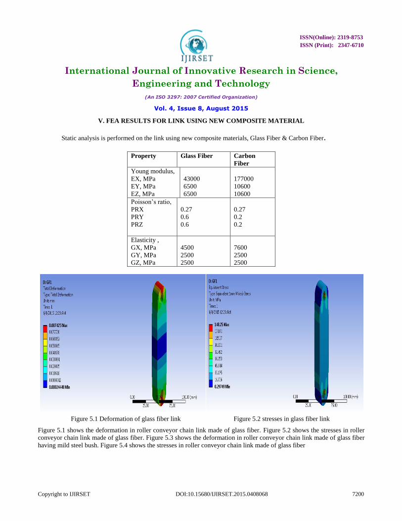
V. FEA RESULTS FOR LINK USING NEW COMPOSITE MATERIAL
Static analysis is performed on the link using new composite materials, Glass Fiber & Carbon Fiber.
Property Glass Fiber Carbon
Fiber
Young modulus,
EX, MPa
EY, MPa
EZ, MPa
43000
6500
6500
177000
10600
10600
Poisson’s ratio,
PRX
PRY
PRZ
0.27
0.6
0.6
0.27
0.2
0.2
Elasticity ,
GX, MPa
GY, MPa
GZ, MPa
4500
2500
2500
7600
2500
2500
Figure 5.1 Deformation of glass fiber link Figure 5.2 stresses in glass fiber link
Figure 5.1 shows the deformation in roller conveyor chain link made of glass fiber. Figure 5.2 shows the stresses in roller
conveyor chain link made of glass fiber. Figure 5.3 shows the deformation in roller conveyor chain link made of glass fiber
having mild steel bush. Figure 5.4 shows the stresses in roller conveyor chain link made of glass fiber

ISSN(Online): 2319-8753
ISSN (Print): 2347-6710
International Journal of Innovative Research in Science,
Engineering and Technology
(An ISO 3297: 2007 Certified Organization)
Vol. 4, Issue 8, August 2015
Copyright to IJIRSET DOI:10.15680/IJIRSET.2015.0408068 7201
Figure 5.3 Deformation in Glass Fiber with Mild Steel bush Figure 5.4 Stresses in Glass Fiber with Mild Steel bush
Figure 5.5 shows the deformation in combination of carbon fiber and mild steel (sandwich) Figure 5.6 shows the stresses in
combination of carbon fiber and mild steel (sandwich)
Figure 5.5 Deformation of Glass fiber and Mild Steel (Sandwich) Figure 5.6 Stresses of Glass fiber and Mild Steel
Figure 5.7 shows the deformation in roller conveyor chain link made of carbon fiber. Figure 5.8 shows the stresses in roller
conveyor chain link made of carbon fiber
Figure 5.7 Deformation in Carbon Fiber Link Figure 5.8 Stresses in Carbon Fiber Link
Figure 5.9 shows the deformation in roller conveyor chain link made of glass fiber having mild steel bush. Figure 5.10
shows the stresses in roller conveyor chain link made of carbon fiber with mild steel bush

ISSN(Online): 2319-8753
ISSN (Print): 2347-6710
International Journal of Innovative Research in Science,
Engineering and Technology
(An ISO 3297: 2007 Certified Organization)
Vol. 4, Issue 8, August 2015
Copyright to IJIRSET DOI:10.15680/IJIRSET.2015.0408068 7202
Figure 5.9 Deformation in CF Link with Mild Steel bush Figure 5.10 Stresses in CF Link with Mild Steel bush
Figure 5.11 shows the deformation of combination of carbon fiber and mild steel (Sandwich). Figure 5.12 shows the
stresses in of combination of carbon fiber and mild steel (Sandwich)
Figure 5.11 Deformation in CF and Mild Steel (Sandwich) Figure 5.12 Stresses in CF and Mild Steel (Sandwich)
The pure carbon fiber link with 6 mm thickness is having the minimum density and weight but the stresses induced
as per the FEA are higher than the stresses induces in the mild steel link. Here we are increasing the thickness by 2 mm to
minimize the stresses. Hence the analysis is done of carbon fiber link with 8mm thickness. Figure 5.13 shows the
deformation in carbon fiber link with 8 mm thickness.

ISSN(Online): 2319-8753
ISSN (Print): 2347-6710
International Journal of Innovative Research in Science,
Engineering and Technology
(An ISO 3297: 2007 Certified Organization)
Vol. 4, Issue 8, August 2015
Copyright to IJIRSET DOI:10.15680/IJIRSET.2015.0408068 7203
Figure 5.13 Deformation in Carbon Fiber with 8 mm Figure 5.14 Stresses in Carbon Fiber with 8 mm thickness
Figure 5.15 shows the deformation of the carbon fiber link with 10 mm thickness. Figure 5.16 shows the stresses in carbon
fiber link with 10 mm thickness
Figure 5.15 Deformation in Carbon Fiber with 10 mm thickness Figure 5.16 Stresses in Carbon Fiber with 10 mm
The stresses induced in the carbon fiber link with 8 mm and 10 mm thickness are higher than the stresses induced
in mild steel link. Hence we are again increasing the thickness by 2 mm. and FEA analysis is done with Carbon fiber link
having 12 mm thickness. Figure 5.17 shows the deformation of the carbon fiber link with 12 mm thickness

ISSN(Online): 2319-8753
ISSN (Print): 2347-6710
International Journal of Innovative Research in Science,
Engineering and Technology
(An ISO 3297: 2007 Certified Organization)
Vol. 4, Issue 8, August 2015
Copyright to IJIRSET DOI:10.15680/IJIRSET.2015.0408068 7204
Figure 5.17 Deformation in Carbon Fiber with 12 mm thickness Figure 5.18 stresses in Carbon Fiber with 12 mm
VI. EXPERIMENTAL RESULTS
On the basis of Finite element analysis it is observed that the glass the roller conveyor chain link made of glass fiber is
having minimum stresses. For the validation purpose a tension test of glass fiber link is carried out on universal testing
machine. Using the attachment the specimen is fixed in universal testing machine. Both the ends are fixed in the universal
testing machine.
Figure 6.1 Glass Fiber Specimen Figure 6.2 Specimens On UTM

ISSN(Online): 2319-8753
ISSN (Print): 2347-6710
International Journal of Innovative Research in Science,
Engineering and Technology
(An ISO 3297: 2007 Certified Organization)
Vol. 4, Issue 8, August 2015
Copyright to IJIRSET DOI:10.15680/IJIRSET.2015.0408068 7205
Figure 6.3 Failure Of Glass Fiber Link Graph 6.1 Load vs. Displacement
Graph 6.1 shows the graph of load vs displacement. There is no deformation in the glass fiber link up to a load of 4000 N.
deformation starts increasing from 4000 N up to a maximum load of 19200 N. With further loading glass fiber link breaks
the maximum deformation in the glass fiber link is 3.8 mm. The ;ink is required to take a maximum load of 11600 N which
well below the maximum load carrying capacity of glass fiber link.
VII.REULTS AND DISCUSSION
SR.
NO
.
Material
Total
Deformation
(mm)
Equivalent
Von Mises
Stress (MPa)
Weight
(kg)
1 MS 0.03938 281.2 0.13446
2 GF 0.08742 148.25 0.10227
3 GF+MS Bush 0.25888 76.149 0.22077
4 GF+MS+GF 0.04847 381.49 0.10111
5 CF 0.07832 511.42 0.03288
6 CF+MS Bush 0.04696 306.67 0.03656
7 CF+MS+CF 0.03586 324.53 0.09156
8 CF 0.05877 383.66 0.04385
9 CF 0.04704 307.01 0.05481
10 CF 0.03921 255.94 0.06577

ISSN(Online): 2319-8753
ISSN (Print): 2347-6710
International Journal of Innovative Research in Science,
Engineering and Technology
(An ISO 3297: 2007 Certified Organization)
Vol. 4, Issue 8, August 2015
Copyright to IJIRSET DOI:10.15680/IJIRSET.2015.0408068 7206
The maximum stress induced in Mild steel link is 281.2 MPa and weight is 0.13446 kg. .FEA is carried out using glass fiber
and carbon fiber with different conditions and thickness. The best results are found with glass fiber having thickness 15 mm
with 24% weight reduction. The maximum stress induced in glass fiber having 15 mm thickness is 148.25 MPa and
maximum deformation is 0.087 mm the carbon fiber link with 12 mm also gives the weight reduction up to 51%.bt glass
fiber link is easily available and cheaper in cost which makes itself a good option for using a alternative for mild steel link.
Fatigue life of glass fiber link as well as carbon fiber link is higher than the mild steel link. Fatigue life of glass fiber link
and carbon fiber link are 1.59e5 and 1.31e5 cycles respectively and that of mild steel link is 8036 cycles at critical sections
As per the tension test performed the maximum load carrying capacity of roller conveyor chain link made of glass fiber is
19200 N. The force acting on roller chain link is about 11600 N. hence the load carrying capacity is well above the required
force
VIII.CONCLUSION
Static analysis was performed to achieve the stresses and deformations and in results it is found that there is a maximum
deformation of 0.039389 mm in the mild steel link and the Corresponding displacements in glass fiber is 0.087 mm. From
the static analysis results, we see that the von-misses stress in the mild steel is 281.2 MPa. And the von-misses stress in
glass fiber is 148.25 MPa. Glass fiber link plate can be suggested for replacing the steel link plate from stress and stiffness
point of view. A comparative study has been made between steel and composite link with respect to strength and weight.
Fatigue life of glass fiber link as well as carbon fiber link is higher than the mild steel link. Fatigue life of glass fiber link
and carbon fiber link are 1.59e5 and 1.31e5 cycles respectively and that of mild steel link is 8036 cycles at critical sections.
As per the tension test performed the maximum load carrying capacity of the glass fiber link is 19200 N which is well
above the requirement. Weight reduction is achieved 24 % with glass fiber, the weight of the glass fiber link is 0.102 kg
and that of mild steel link is 0.135 kg. It must be noted that in typical industrial application thousands of such link will be
needed. Thus, the weight and material saving will have significant impact on cost of the chain
REFERENCES
1) Bhoite Tushar, Prashant M. Pawar & Bhaskar D. Gaikwad “Fea Based Study Of Effect Of Radial Variation Of Outer Link In A Typical Roller Chain Link Assembly”, Ijmie,2012
2) M.D Jagtap, Gaikwad B. D, Pawar P. M.”Study Of Roller Conveyor Chain Strip Under Tensile Loading”, Ijmer,2014
3) Patil Suhas, M. Shinde And R.B. Patil, “Design And Analysis Of A Roller Conveyor System For Weight Optimization And Material Saving”, Ijet,
2014
4) American Chain Association, Second Edition, “Standard Hand Book Of Chains- Chains For Power Transmission And Material Handeling,” 2006.
5) Reddy, A. V.. “Aeronautical and Engineering Component Failure. United States Of America”: Crc Press 2004
6) Aliya, D.The" “Failure Analysis Process. An Overview”. Materials Park: Asm International 2003
7) Bošnjak, S. M., Arsic, M. A., N.Odanovic, Z. D & Dordevic, M. D. (2011). “Failure Analysis of the Stacker Crawler Chain Link .Engineering
Procedia”, 10: 2244–2249.
8) Kerremans, V., Rolly, T., Baets, P. D., Pauw, J. D., Sukumaran, J., & Delgado, Y. P. “Wear Of Conveyor Chains With Polymer Rollers. Sustainable
Construction And Design” 2011
9) Pankaj Saini, Ashish Goel, Dushyant Kumar, “Design And Analysis Of Compositeleaf Spring For Light Vehicles” Moradabad Institute Of
Technology, Moradabad, Uttar Pradesh, India. 2013
10) Dakshraj Kothari,Rajendra Prasad Sahu And Rajesh Satankar,, “Comparison Of Performance Of Two Leaf Spring Steels Used For Light Passenger
Vehicle”, Vsrd-Map 2249-8303 Volume2 (1), 9-16.2012