Embed Size (px)
Citation preview
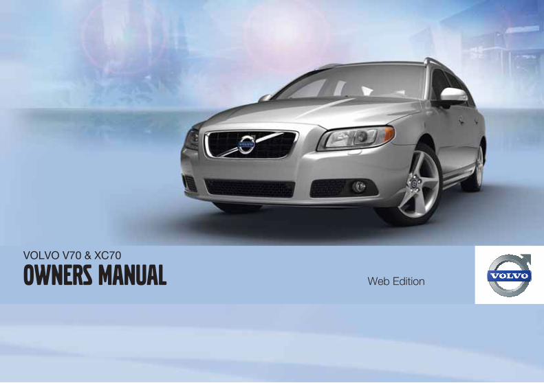
VOLVO V70 & XC70
Owners Manual Web Edition


DEAR VOLVO OWNERTHANK YOU FOR CHOOSING VOLVO
We hope you will enjoy many years of driving pleasure in your Volvo.The car has been designed for the safety and comfort of you and yourpassengers. Volvo is one of the safest cars in the world. Your Volvohas also been designed to satisfy all current safety and environmentalrequirements.
In order to increase your enjoyment of the car, we recommend thatyou familiarise yourself with the equipment, instructions and mainte-nance information contained in this owner's manual.

Table of contents
4 * Option/accessory, for more information, see Introduction.
0000 Introduction
Important information................................. 8Volvo and the environment....................... 11
0101 Safety
Seatbelts .................................................. 16Airbags...................................................... 19Activating/deactivating the airbag*........... 22Side airbags (SIPS bags) ......................... 24Inflatable Curtain (IC) ............................... 26WHIPS ...................................................... 27When the systems deploy ........................ 29Safety mode.............................................. 30Child safety............................................... 31 02
02 Locks and alarm
Remote control key/key blade.................. 44Privacy locking*......................................... 49Battery replacement, remote control key/PCC*......................................................... 51Keyless drive*............................................ 53Locking/unlocking..................................... 56Child safety locks...................................... 61Alarm*....................................................... 62

Table of contents
* Option/accessory, for more information, see Introduction. 5
0303 Your driving environment
Instruments and controls.......................... 66Key positions............................................ 74Seats......................................................... 76Steering wheel.......................................... 81Lighting..................................................... 82Wipers and washing.................................. 92Windows, rearview and door mirrors........ 95Compass*............................................... 100Power sunroof*....................................... 101Alcoguard*.............................................. 103Starting the engine.................................. 107Starting the engine – Flexifuel................. 109Starting the engine – external battery..... 111Gearboxes............................................... 112All-wheel drive – AWD*........................... 117Foot brake............................................... 118Hill Descent Control (HDC)..................... 120Parking brake.......................................... 122
HomeLink *............................................ 125
0404 Comfort and driving pleasure
Menus and messages............................. 130Climate control........................................ 137Fuel-driven engine block heater and pas-senger compartment heater*.................. 144Additional heater*.................................... 147Audio system.......................................... 148RSE - Rear Seat Entertainment system -Dual Screen* .......................................... 161Trip computer......................................... 166DSTC – Stability and traction control sys-tem.......................................................... 168Adapting driving characteristics............. 170Cruise control*........................................ 171Adaptive cruise control*.......................... 173Distance Alert*........................................ 181Collision Warning with Auto Brake*........ 184Driver Alert System – DAC*..................... 190Driver Alert System - LDW*..................... 193Park assist syst*...................................... 196BLIS* – Blind Spot Information System. . 199Comfort inside the passenger compart-ment........................................................ 202Bluetooth handsfree*.............................. 205Built-in phone*........................................ 210
0505 During your journey
Recommendations during driving........... 216Refuelling................................................ 219Fuel......................................................... 220Loading................................................... 224Cargo area.............................................. 228Driving with a trailer................................ 231Towing and recovery.............................. 237

Table of contents
6 * Option/accessory, for more information, see Introduction.
0606 Wheels and tyres
General ................................................... 242Changing wheels ................................... 246Tyre pressure ......................................... 248Warning triangle and first-aid kit*............ 249Emergency puncture repair (TMK)* ........ 250
0707 Maintenance and service
Engine compartment............................... 256Lamps..................................................... 263Wiper blades and washer fluid................ 269Battery..................................................... 271Fuses...................................................... 274Car care.................................................. 282
0808 Specifications
Type designations................................... 290Dimensions and weights......................... 292Engine specifications.............................. 298Engine oil................................................ 300Fluids and lubricants............................... 302Fuel......................................................... 304Wheel and tyres, dimensions and pres-sure ........................................................ 308Electrical system..................................... 313Type approval......................................... 314Symbols in the display............................ 315

Table of contents
7
0909 Alphabetical Index
Alphabetical Index.................................. 318

Introduction
Important information
8 * Option/accessory, for more information, see Introduction.
Reading the Owner's Manual
Introduction
A good way of getting to know your new car isto read the owner's manual, ideally before yourfirst journey. This will give you the opportunityto familiarise yourself with new functions, tosee how best to handle the car in different sit-uations, and to make the best use of all thecar's features. Please pay attention to thesafety instructions contained in the manual.
The specifications, design features and illus-trations in this owner's manual are not binding.We reserve the right to make modificationswithout prior notice.© Volvo Car Corporation
Option
All types of option/accessory are marked withan asterisk*.
In addition to standard equipment, this manualalso describes options (factory fitted equip-ment) and certain accessories (retrofitted extraequipment).
The equipment described in the owner's man-ual is not available in all cars - they have dif-ferent equipment depending on adaptationsfor the needs of different markets and nationalor local laws and regulations.
In the event of uncertainty over what is stand-ard or an option/accessory, contact a Volvodealer.
Special texts
WARNING
Warning texts advise of a risk of personalinjury.
IMPORTANT
Important texts advise of a risk of materialdamage.
NOTE
NOTE texts give advice or tips that facilitatethe use of features and functions for exam-ple.
Footnote
There is footnote information in the owner'smanual that is located at the bottom of thepage. This information is an addition to the textthat it refers to via a number. If the footnoterefers to text in a table then letters are usedinstead of numbers for referral.
Message texts
There are displays in the car that show textmessages. These text messages are high-
lighted in the owner's manual by means of thetext being slightly larger and printed in grey.Examples of this are in menu texts and mes-sage texts on the information display (e.g.Audio settings).
Decals
The car contains different types of decal whichare designed to convey important informationin a simple and clear manner. The decals in thecar have the following descending degree ofimportance for the warning/information.
Warning for personal injury
G031590
Black ISO symbols on yellow warning field,white text/image on black message field. Usedto indicate the presence of danger which, if the

Introduction
Important information
9
warning is ignored, may result in serious per-sonal injury or fatality.
Risk of property damage
G031592
White ISO symbols and white text/image onblack or blue warning field and message field.Used to indicate the presence of danger which,if the warning is ignored, may result in damageto property.
Information
G031593
White ISO symbols and white text/image onblack message field.
NOTE
The labels shown in the owner's manual arenot provided as exact reproductions ofthose in the car. The purpose is to showtheir approximate appearance and locationin the car. The information that applies toyour car in particular is available on the labelin question in your car.
Procedure lists
Procedures where action must be taken in acertain sequence are numbered in the owner'smanual.
When there is a series of illustrations forstep-by-step instructions each step isnumbered in the same way as the corres-ponding illustration.
There are numbered lists with letters adja-cent to the series of illustrations where theorder of the instructions is not significant.
Arrows appear numbered and unnum-bered and are used to illustrate a move-ment.
If there is no series of illustrations for step-by-step instructions then the different steps arenumbered with normal numbers.
Position lists
Red circles containing a number are usedin overview images where different com-ponents are pointed out. The numberrecurs in the position list featured in con-nection with the illustration that describesthe item.
Bulleted lists
A bulleted list is used when there is a list ofpoints in the owner's manual.
Example:

Introduction
Important information
10
• Coolant
• Engine oil
To be continued
��� This symbol is located furthest down to theright when a section continues on the followingpage.
Recording data
The driving and safety systems in the car usecomputers which check and share informationwith each other on the car's function. One ormore of these computers may store informa-tion on the systems they check during normaldriving, during the course of a collision or near-collision. Stored information may be used by:
• Volvo Car Corporation
• Service or repair workshops
• Police or other authorities
• Other parties who claim legal entitlementfor access to the information or someonewho has permission from the owner toaccess the information.
Accessories and extra equipment
The incorrect connection and installation ofaccessories can negatively affect the car'selectrical system. Certain accessories onlyfunction when their associated software isinstalled in the car's computer system. Volvotherefore recommends that you always con-tact an authorised Volvo workshop beforeinstalling accessories which are connected toor affect the electrical system.
Information on the Internet
At www.volvocars.com there is further infor-mation concerning your car.

Introduction
Volvo and the environment
* Option/accessory, for more information, see Introduction. 11
Volvo Cars' environmental philosophy
G000000
Environmental care is one of Volvo Car Corpo-ration's core values which influence all opera-tions. We also believe that our customers shareour consideration for the environment.
Your Volvo complies with strict internationalenvironmental standards and is also manufac-tured in one of the cleanest and most resource-efficient plants in the world. Volvo Car Corpo-ration has global ISO certification, whichincludes the environmental standard ISO14001 covering all factories and several of ourother units. We also set requirements for ourpartners so that they work systematically withenvironmental issues.
fuel consumption
Volvo cars have competitive fuel consumptionin each of their respective classes. Lower fuelconsumption generally results in lower emis-sion of the greenhouse gas, carbon dioxide.
It is possible for the driver to influence fuel con-sumption. For more information read under theheading, Reducing environmental impact.
Efficient emission control
Your Volvo is manufactured following the con-cept "Clean inside and out" – a concept thatencompasses a clean interior environment aswell as highly efficient emission control. In
many cases the exhaust emissions are wellbelow the applicable standards.
Clean air in the passenger compartment
A passenger compartment filter prevents dustand pollen from entering the passenger com-partment via the air intake.
A sophisticated air quality system, IAQS* (Inte-rior Air Quality System) ensures that the incom-ing air is cleaner than the air in the traffic out-side.
The system consists of an electronic sensorand a carbon filter. The incoming air is moni-tored continuously and if there is an increase in
Introduction
Volvo and the environment
12 * Option/accessory, for more information, see Introduction.
the level of certain unhealthy gases such ascarbon monoxide then the air intake is closed.Such a situation may arise in heavy traffic,queues and tunnels for example.
The entry of nitrous oxides, ground-level ozoneand hydrocarbons is prevented by the carbonfilter.
Textile standard
The interior of a Volvo is designed to be plea-sant and comfortable, even for people withcontact allergies and for asthma sufferers.Extreme attention has been given to choosingenvironmentally-compatible materials. Thismeans that they also fulfil the requirements inthe Oeko-Tex 100 standard1, a major advancetowards a healthier passenger compartmentenvironment.
Oeko-Tex certification covers seatbelts, car-pets and fabrics for example. The leather in theupholstery undergoes chromium-free tanningand fulfils the certification requirements.
Volvo workshops and the environment
Regular maintenance creates the conditionsfor a long service life and low fuel consumptionfor your car. In this way you contribute to acleaner environment. When Volvo's workshopsare entrusted with the service and mainte-nance of your car it becomes part of our sys-
tem. Volvo makes clear demands regarding theway in which our workshops are designed inorder to prevent spills and discharges into theenvironment. Our workshop staff have theknowledge and the tools required to guaranteegood environmental care.
Reducing environmental impact
You can easily help reduce environmentalimpact - here are a few tips:
• Avoid letting the engine idle - switch off theengine when stationary for longer periods.Pay attention to local regulations.
• Drive economically - think ahead.
• Perform service and maintenance inaccordance with the owner's manual'sinstructions - follow the Service and War-ranty Booklet's recommended intervals.
• If the car is equipped with an engine blockheater*, use it before starting from cold - itimproves starting capacity and reduceswear in cold weather and the engine rea-ches normal operating temperature morequickly, which lowers consumption andreduces emissions.
• High speed increases consumption con-siderably due to increased wind resistance- a doubling of speed increases wind resis-tance 4 times.
• Always dispose of environmentally hazar-dous waste, such as batteries and oils, inan environmentally safe manner. Consult aworkshop in the event of uncertainty abouthow this type of waste should be discarded- an authorised Volvo workshop is recom-mended.
Following this advice can save money, theplanet's resources are saved and the car'sdurability is extended. For more informationand further advice, see the pages 216 and306.
Recycling
As a part of Volvo's environmental work, it isimportant that the car is recycled in an envi-ronmentally sound manner. Almost all of thecar can be recycled. The last owner of the caris therefore requested to contact a dealer forreferral to a certified/approved recyclingfacility.
The owner's manual and theenvironment
The FSC symbol shows that the paper pulp inthis publication comes from FSC certified for-ests or other controlled sources.
1 More information on www.oekotex.com
Introduction
Volvo and the environment
13

14 * Option/accessory, for more information, see Introduction.
Seatbelts ................................................................................................ 16Airbags.................................................................................................... 19Activating/deactivating the airbag*......................................................... 22Side airbags (SIPS bags) ....................................................................... 24Inflatable Curtain (IC) ............................................................................. 26WHIPS .................................................................................................... 27When the systems deploy ...................................................................... 29Safety mode............................................................................................ 30Child safety............................................................................................. 31

SAFETY
01 Safety
Seatbelts 01
16
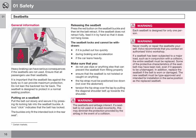
General information
Heavy braking can have serious consequencesif the seatbelts are not used. Ensure that allpassengers use their seatbelts.
It is important that the seatbelt lies against thebody so it can provide maximum protection.Do not lean the backrest too far back. Theseatbelt is designed to protect in a normalseating position.
Putting on a seatbelt
Pull the belt out slowly and secure it by press-ing its locking tab into the seatbelt buckle. Aloud "click" indicates that the belt has locked.
The buckles only fit the intended lock in the rearseat1.
Releasing the seatbelt
Press the red button on the seatbelt buckle andthen let the belt retract. If the seatbelt does notretract fully, feed it in by hand so that it doesnot hang loose.
The seatbelt locks and cannot be with-
drawn:
• if it is pulled out too quickly
• during braking and acceleration
• if the car leans heavily.
Make sure that you:
• do not use clips or anything else that canprevent the seatbelt from fitting properly
• ensure that the seatbelt is not twisted orcaught on anything
• the hip strap must be positioned low down(not over the abdomen)
• tension the hip strap over the lap by pullingthe diagonal shoulder belt up towards theshoulder.
WARNING
The seatbelts and airbags interact. If a seat-belt is not used or is used incorrectly, thismay diminish the protection provided by theairbag in the event of a collision.
WARNING
Each seatbelt is designed for only one per-son.
WARNING
Never modify or repair the seatbelts your-self. Volvo recommends that you contact anauthorised Volvo workshop.
If a seatbelt has been subjected to a majorload, such as in conjunction with a collision,the entire seatbelt must be replaced. Someof the protective characteristics of the seat-belt may have been lost, even if it appearsto be undamaged. In addition, replace theseatbelt if the belt is worn or damaged. Thenew seatbelt must be type-approved andintended for installation in the same positionas the replaced seatbelt.
1 Certain markets.

01 Safety
Seatbelts 01
��
17
Seatbelts and pregnancy
G02
0998
The seatbelt should always be worn duringpregnancy. But it is then crucial that it be wornin the correct way. The diagonal section shouldwrap over the shoulder then be routed betweenthe breasts and to the side of the abdomen.
The lap section should lay flat over the thighsand as low as possible under the abdomen. –It must never be allowed to ride upward.Remove the slack from the seatbelt and ensurethat it fits as close to the body as possible. Inaddition, check that there are no twists in theseatbelt.
As the pregnancy progresses, pregnant driversshould adjust their seats and steering wheelsuch that they can easily maintain control of thevehicle as they drive (which means that theymust be able to easily operate the foot pedals
and steering wheel). The aim should be to posi-tion the seat with as large a distance as possi-ble between abdomen and steering wheel.
Seatbelt reminder
G01
7726
Unbelted occupants will be reminded to fastentheir seatbelts by means of an audio and visualreminder. The audio reminder is speeddependent, and in some cases time depend-ent. The visual reminder is located in the roofconsole and the combined instrument panel.
Child seats are not covered by the seatbeltreminder system.
Rear seat
The seatbelt reminder in the rear seat has twosubfunctions:
• Provides information on which seatbeltsare being used in the rear seat. A messageappears in the information display whenthe seatbelts are in use, or if one of the reardoors has been opened. The message iscleared automatically after driving forapproximately 30 seconds or after press-ing the indicator stalk's READ button.
• Provides a warning if one of the rear seat-belts is unfastened during travel. Thiswarning takes the form of a message onthe information display along with theaudio/visual signal. The warning stopswhen the seatbelt is re-fastened, or it canalso be acknowledged manually by press-ing the READ button.
The message on the information display show-ing which seatbelts are in use is always avail-able. Press the READ button to see storedmessages.

01 Safety
Seatbelts 01
18
Certain markets
An acoustic signal and indicator lamp remindthe driver and front seat passenger to use aseatbelt if either of them is not wearing one. Atlow speed, the audio reminder will sound forthe first 6 seconds.
Seatbelt tensioner
All the seatbelts are equipped with belt ten-sioners. A mechanism in the seatbelt tensionertightens the seatbelt in the event of a suffi-ciently violent collision. The seatbelt then pro-vides more effective restraint for the occu-pants.
WARNING
Never insert the tongue of the passenger'sseatbelt into the buckle on the driver's side.Always insert the tongue of the seatbelt intothe buckle on the correct side. Do not makeany damages on seatbelts nor insert anyforeign objects into a buckle. The seatbeltsand buckles would then possibly not func-tion as intended in the event of a collision.There is a risk of serous injury.
01 Safety
Airbags 01
��
19
Warning symbol on the combinedinstrument panel
The warning symbol in the combined instru-ment panel illuminates when the remote con-trol key is in key position II or III. The symbolclears after approx. 6 seconds provided theairbag system is fault-free.
WARNING
If the warning symbol for the airbag systemremains illuminated or illuminates while driv-ing, it means that the airbag system doesnot have full functionality. The symbol indi-cates a fault in the seatbelt tensioner sys-tem, SIPS, the IC system or some other faultin the system. Volvo recommends that youcontact an authorised Volvo workshopimmediately.
As well as the warning symbol, a message mayappear on the information display in appropri-ate cases. If the warning symbol malfunctions,the warning triangle illuminates and SRS
Airbag Service required or SRS Airbag
Service urgent appears in the display. Volvorecommends that you contact an authorisedVolvo workshop immediately.
Airbag system
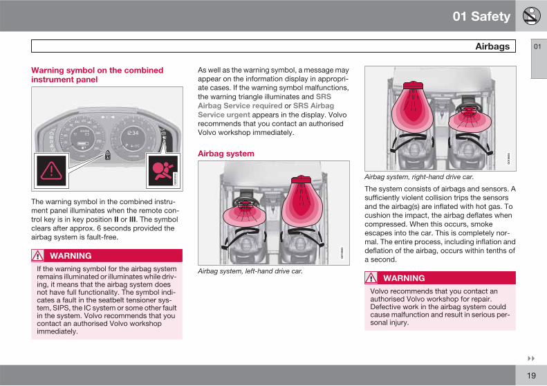
G01
8665
Airbag system, left-hand drive car.
G01
8666
Airbag system, right-hand drive car.
The system consists of airbags and sensors. Asufficiently violent collision trips the sensorsand the airbag(s) are inflated with hot gas. Tocushion the impact, the airbag deflates whencompressed. When this occurs, smokeescapes into the car. This is completely nor-mal. The entire process, including inflation anddeflation of the airbag, occurs within tenths ofa second.
WARNING
Volvo recommends that you contact anauthorised Volvo workshop for repair.Defective work in the airbag system couldcause malfunction and result in serious per-sonal injury.
01 Safety
Airbags 01
20
NOTE
The sensors react differently depending onthe course of the collision and whether ornot the seatbelts on the driver and passen-ger side are used.
It is therefore possible that only one (ornone) of the airbags may inflate in a colli-sion. The airbag system senses the force ofthe collision on the car and adapts accord-ingly so that one or more airbags aredeployed.
The capacity of the airbags is also adaptedto the collision force to which the vehicle issubjected.
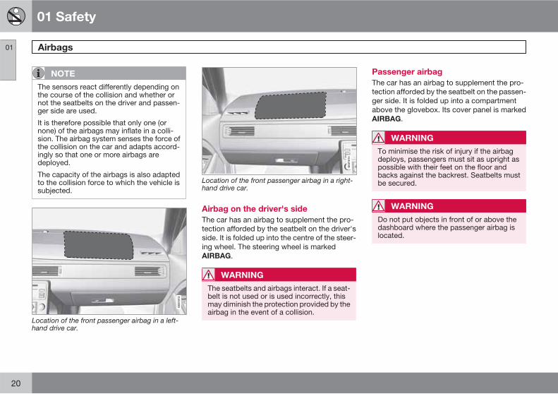
Location of the front passenger airbag in a left-hand drive car.
Location of the front passenger airbag in a right-hand drive car.
Airbag on the driver's side
The car has an airbag to supplement the pro-tection afforded by the seatbelt on the driver'sside. It is folded up into the centre of the steer-ing wheel. The steering wheel is markedAIRBAG.
WARNING
The seatbelts and airbags interact. If a seat-belt is not used or is used incorrectly, thismay diminish the protection provided by theairbag in the event of a collision.
Passenger airbag
The car has an airbag to supplement the pro-tection afforded by the seatbelt on the passen-ger side. It is folded up into a compartmentabove the glovebox. Its cover panel is markedAIRBAG.
WARNING
To minimise the risk of injury if the airbagdeploys, passengers must sit as upright aspossible with their feet on the floor andbacks against the backrest. Seatbelts mustbe secured.
WARNING
Do not put objects in front of or above thedashboard where the passenger airbag islocated.

01 Safety
Airbags 01
21
WARNING
Never place a child in a child seat or on abooster cushion in the front seat if the airbagis activated.
Never allow anybody to stand or sit in frontof the front passenger seat.
No one shorter than 140 cm should ever sitin the front passenger seat if the airbag isactivated.
Failure to follow the advice given above canendanger life.

01 Safety
Activating/deactivating the airbag* 01
22 * Option/accessory, for more information, see Introduction.
Key switch off - PACOS*
General information
The airbag for the front passenger seat can bedeactivated if the car is equipped with a switch,PACOS (Passenger Airbag Cut Off Switch). Forinformation on how to activate/deactivate, seeunder the heading Activating/deactivating.
Key switch off/switch
The switch for the passenger airbag (PACOS)is located on the passenger end of the instru-ment panel and is accessible when the pas-senger door is open (see under the headingbelow, Activating/deactivating).
Check that the switch is in the required posi-tion. Volvo recommends that the remote con-trol key's key blade be used to change posi-tion.
For information on the key blade, seepage 47.
WARNING
Failure to follow the advice given abovecould endanger the life of passengers in thecar.
WARNING
If the car is equipped with a front passengerairbag, but does not have a PACOS switch(Passenger Airbag Cut Off Switch), then theairbag will always be activated.
WARNING
Never place a child in a child seat or on abooster cushion in the front seat if the airbagis activated and the symbol in the roofconsole is illuminated. Failure to follow thisadvice could endanger the life of the child.
WARNING
Do not allow anyone to sit in the front pas-senger seat if the message in the roof panel(see page 23) indicates that the airbag isdeactivated and if the warning symbol forthe airbag system is also displayed in thecombined instrument panel. This indicatesthat there has been a severe malfunction.Visit a workshop as soon as possible. Volvorecommends that you contact an author-ised Volvo workshop.
Activating/deactivating
Switch location
The airbag is activated. With the switch inthis position, persons taller than 140 cmcan sit in the front passenger seat, butnever children in a child seat or on abooster cushion.
The airbag is deactivated. With the switchin this position, children in a child seat oron a booster cushion can sit in the frontpassenger seat, but never persons tallerthan 140 cm.

01 Safety
Activating/deactivating the airbag* 01
* Option/accessory, for more information, see Introduction. 23
WARNING
Activated airbag (passenger seat):
Never place a child in a child seat or on abooster cushion on the front passenger seatwhen the airbag is activated. This applies toeveryone shorter than 140 cm.
Deactivated airbag (passenger seat):
No one taller than 140 cm should ever sit inthe front passenger seat when the airbag isdeactivated.
Failure to follow the advice given abovecould endanger life.
Messages
2
2
G01
7724
Indicator showing that the passenger airbag isdeactivated.
A text message and a symbol in the roof panelindicate that the airbag for the front passengerseat is deactivated (see preceding illustration).
G01
7800
Indicator showing that the passenger airbag isactivated.
A warning symbol in the roof panel indicatesthat the airbag for the front passenger seat isactivated (see preceding illustration).
NOTE
When the remote control key is turned tokey position II or III the warning symbol forthe airbag is displayed on the combinedinstrument panel for approx. 6 seconds (seepage 19).
Following which, the indicator in the roofconsole is illuminated showing the correctstatus for the front passenger seat airbag.For more information about the different keypositions for the remote control key, seepage 74.
01 Safety
Side airbags (SIPS bags) 01
24
Side airbag
G03
2949
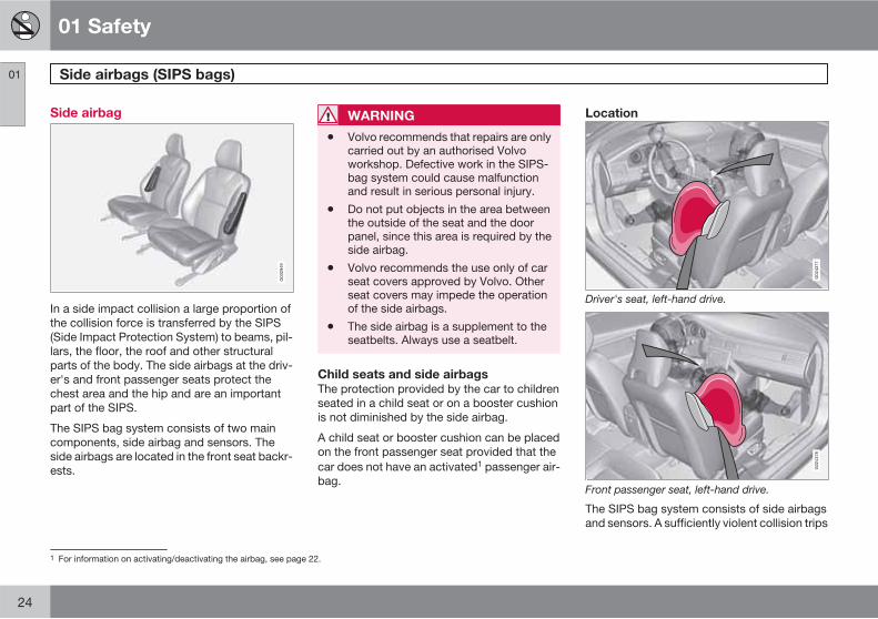
In a side impact collision a large proportion ofthe collision force is transferred by the SIPS(Side Impact Protection System) to beams, pil-lars, the floor, the roof and other structuralparts of the body. The side airbags at the driv-er's and front passenger seats protect thechest area and the hip and are an importantpart of the SIPS.
The SIPS bag system consists of two maincomponents, side airbag and sensors. Theside airbags are located in the front seat backr-ests.
WARNING
• Volvo recommends that repairs are onlycarried out by an authorised Volvoworkshop. Defective work in the SIPS-bag system could cause malfunctionand result in serious personal injury.
• Do not put objects in the area betweenthe outside of the seat and the doorpanel, since this area is required by theside airbag.
• Volvo recommends the use only of carseat covers approved by Volvo. Otherseat covers may impede the operationof the side airbags.
• The side airbag is a supplement to theseatbelts. Always use a seatbelt.
Child seats and side airbags
The protection provided by the car to childrenseated in a child seat or on a booster cushionis not diminished by the side airbag.
A child seat or booster cushion can be placedon the front passenger seat provided that thecar does not have an activated1 passenger air-bag.
Location
G02
4377
Driver's seat, left-hand drive.
G02
4378
Front passenger seat, left-hand drive.
The SIPS bag system consists of side airbagsand sensors. A sufficiently violent collision trips
1 For information on activating/deactivating the airbag, see page 22.
01 Safety
Side airbags (SIPS bags) 01
25
the sensors and the side airbags are inflated.The airbag inflates between the occupant andthe door panel and thereby cushions the initialimpact. The airbag deflates when compressedby the collision. The side airbag is normally onlydeployed on the side of the collision.
01 Safety
Inflatable Curtain (IC) 01
26
Properties
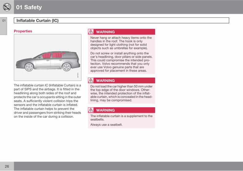
The inflatable curtain IC (Inflatable Curtain) is apart of SIPS and the airbags. It is fitted in theheadlining along both sides of the roof andprotects the car's occupants sitting in the outerseats. A sufficiently violent collision trips thesensors and the inflatable curtain is inflated.The inflatable curtain helps to prevent thedriver and passengers from striking their headson the inside of the car during a collision.
WARNING
Never hang or attach heavy items onto thehandles in the roof. The hook is onlydesigned for light clothing (not for solidobjects such as umbrellas for example).
Do not screw or install anything onto thecar's headlining, door pillars or side panels.This could compromise the intended pro-tection. Volvo recommends that you onlyever use Volvo genuine parts that areapproved for placement in these areas.
WARNING
Do not load the car higher than 50 mm underthe top edge of the door windows. Other-wise, the intended protection of the inflat-able curtain, which is concealed in the head-lining, may be compromised.
WARNING
The inflatable curtain is a supplement to theseatbelts.
Always use a seatbelt.
01 Safety
WHIPS 01
��
27
Protection against whiplash injury –WHIPS
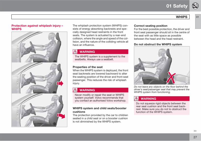
The whiplash protection system (WHIPS) con-sists of energy absorbing backrests and spe-cially designed head restraints in the frontseats. The system is actuated by a rear-endcollision, where the angle and speed of the col-lision, and the nature of the colliding vehicle allhave an influence.
WARNING
The WHIPS system is a supplement to theseatbelts. Always use a seatbelt.
Properties of the seat
When the WHIPS system is deployed, the frontseat backrests are lowered backward to alterthe seating position of the driver and front seatpassenger. This reduces the risk of whiplashinjury.
WARNING
Never modify or repair the seat or WHIPSsystem yourself. Volvo recommends thatyou contact an authorised Volvo workshop.
WHIPS system and child seats/booster
cushions
The protection provided by the car to childrenseated in a child seat or on a booster cushionis not diminished by the WHIPS system.
Correct seating position
For the best possible protection, the driver andfront seat passenger should sit in the centre ofthe seat with as little space as possiblebetween the head and the head restraint.
Do not obstruct the WHIPS system
Do not leave any objects on the floor behind thedriver's seat/passenger seat that may prevent theWHIPS system from functioning.
WARNING
Do not squeeze rigid objects between therear seat cushion and the front seat back-rest. Make sure you do not to obstruct thefunction of the WHIPS system.

01 Safety
WHIPS 01
28
Do not place objects on the rear seat that mayprevent the WHIPS system from functioning.
WARNING
If a rear seat backrest is folded down, thecorresponding front seat must be movedforward so that it does not touch the foldedbackrest.
WARNING
If a seat has been subjected to extremeforces, such as due to a rear-end collision,the WHIPS system must be checked. Volvorecommends that it is checked by anauthorised Volvo workshop.
Part of the WHIPS system's protectivecapacity may have been lost even if theseats appear to be undamaged.
Volvo recommends that you contact anauthorised Volvo workshop to have the sys-tem checked even after a minor rear-endcollision.
01 Safety
When the systems deploy 01
29
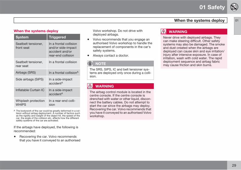
When the systems deploy
System Triggered
Seatbelt tensioner,front seat
In a frontal collisionand/or side-impactaccident and/orrear-end collision
Seatbelt tensioner,rear seat
In a frontal collision
Airbags (SRS) In a frontal collisionA
Side airbags (SIPS) In a side-impactaccidentA
Inflatable Curtain IC In a side-impactaccidentA
Whiplash protectionWHIPS
In a rear-end colli-sion
A The bodywork of the car could be greatly deformed in a col-lision without airbag deployment. A number of factors suchas the rigidity and weight of the object hit, the speed of thecar, the angle of the collision etc. affects how the differentsafety systems of the car are activated.
If the airbags have deployed, the following isrecommended:
• Recovering the car. Volvo recommendsthat you have it conveyed to an authorised
Volvo workshop. Do not drive withdeployed airbags.
• Volvo recommends that you engage anauthorised Volvo workshop to handle thereplacement of components in the car'ssafety systems.
• Always contact a doctor.
NOTE
The SRS, SIPS, IC and belt tensioner sys-tems are deployed only once during a colli-sion.
WARNING
The airbag control module is located in thecentre console. If the centre console isdrenched with water or other liquid, discon-nect the battery cables. Do not attempt tostart the car since the airbags may deploy.Recovering the car. Volvo recommends thatyou have it conveyed to an authorised Volvoworkshop.
WARNING
Never drive with deployed airbags. Theycan make steering difficult. Other safetysystems may also be damaged. The smokeand dust created when the airbags aredeployed can cause skin and eye irritation/injury after intensive exposure. In case ofirritation, wash with cold water. The rapiddeployment sequence and airbag fabricmay cause friction and skin burns.

01 Safety
Safety mode 01
30
Driving after a collision
G02
1062
If the car is involved in a collision, the textSafety mode See manual may appear on theinformation display. This means that the carhas reduced functionality. Safety mode is aprotective state that is enforced when the col-lision may have damaged any of the car's vitalfunctions, such as the fuel lines, sensors forone of the safety systems, or the brake system.
Attempting to start the car
First, check that no fuel is leaking from the car.There must be no smell of fuel either.
If everything seems normal and you havechecked for indications of fuel leakage, youmay attempt to start the car.
Remove the remote control key and open thedriver's door. If a message is now shown to the
effect that the ignition is on, press the startbutton. Then close the door and reinsert theremote control key. The car's electronics willnow try to reset themselves to normal mode.Then try to start the car.
If the message Safety mode See manual isstill shown on the display then the car must notbe driven or towed, but a vehicle recovery serv-ice used instead. Even if the car appears to bedriveable, hidden damage may make the carimpossible to control once moving.
Moving the car
If Normal mode is shown after Safety mode
See manual has been reset, the car can bemoved carefully out of a dangerous position.Do not move the car further than necessary.
WARNING
Never attempt to repair your car or reset theelectronics yourself if the car has been insafety mode. This could result in personalinjury or the car not functioning as normal.Volvo recommends that you engage anauthorised Volvo workshop to check andrestore the car to normal status after Safetymode See manual has been displayed.
WARNING
Never, under any circumstances, attempt torestart the car if it smells of fuel when theSafety mode message is displayed. Leavethe car at once.
WARNING
If the car is in safety mode it must not betowed. It must be transported from its loca-tion. Volvo recommends that it is transpor-ted to an authorised Volvo workshop.

01 Safety
Child safety 01
��
31
Children should sit comfortably andsafely
Volvo recommends that children travel in rear-facing child seats until as late an age as pos-sible, at least until 3-4 years of age, and thenfront-facing booster cushions/child seats untilup to 10 years of age.
The position of a child in the car and the choiceof equipment are dictated by the child's weightand size, for more information, see page 33.
NOTE
Regulations regarding the placement ofchildren in cars vary from country to coun-try. Check what does apply.
Children of all ages and sizes must always sitcorrectly secured in the car. Never allow a childto sit on the knee of a passenger.
Volvo has child safety equipment (child seats,booster cushions & attachment devices) whichis designed for your particular car. Using Vol-vo's child safety equipment provides you withoptimum conditions for your child to travelsafely in the car. Furthermore, the child safetyequipment fits and is easy to use.
NOTE
In the event of questions when fitting childsafety products, contact the manufacturerfor clearer instructions.
Child seats
G02
0739
Child seats and airbags are not compatible.
NOTE
When using child safety products it isimportant to read the installation instruc-tions included.
Do not attach the straps for the child seat tothe horizontal adjustment bar, springs, rails or
beams under the seat. Sharp edges can dam-age the straps.
Look in the installation instructions for the childseat for the correct fitting.
Location of child seats
You may place:
• a child seat/booster cushion on the pas-senger seat, provided the passenger air-bag is not activated1.
• one or more child seats/booster cushionsin the rear seat.
Always fit child seats/booster cushions in therear seat if the passenger airbag is activated. Ifa child is sitting on the front passenger seatthen he/she could suffer serious injury if theairbag deploys.
1 For information on activated/deactivated airbag, see page 22.
01 Safety
Child safety 01
32
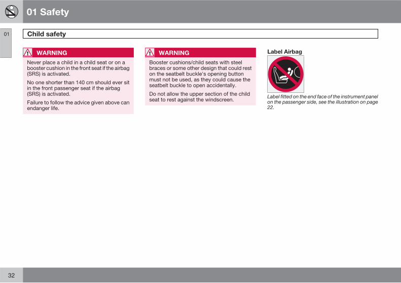
WARNING
Never place a child in a child seat or on abooster cushion in the front seat if the airbag(SRS) is activated.
No one shorter than 140 cm should ever sitin the front passenger seat if the airbag(SRS) is activated.
Failure to follow the advice given above canendanger life.
WARNING
Booster cushions/child seats with steelbraces or some other design that could reston the seatbelt buckle's opening buttonmust not be used, as they could cause theseatbelt buckle to open accidentally.
Do not allow the upper section of the childseat to rest against the windscreen.
Label Airbag
Label fitted on the end face of the instrument panelon the passenger side, see the illustration on page22.
01 Safety
Child safety 01
��
33
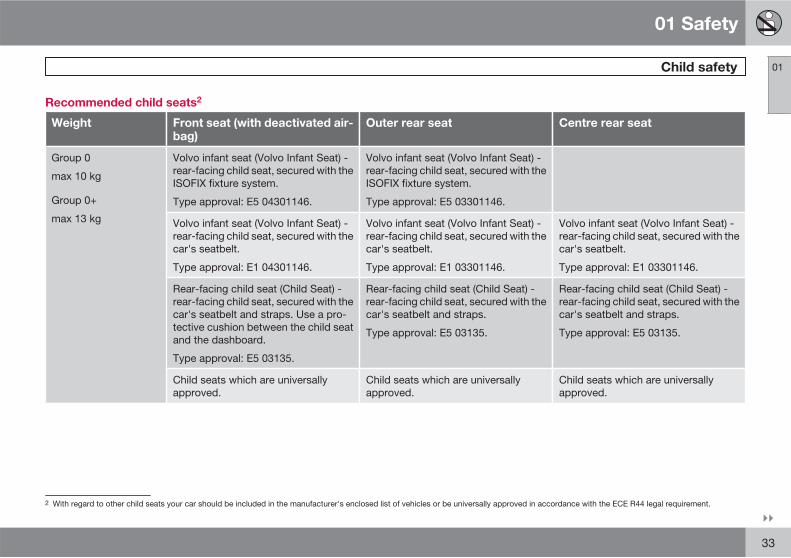
Recommended child seats2
Weight Front seat (with deactivated air-bag)
Outer rear seat Centre rear seat
Group 0
max 10 kg
Group 0+
max 13 kg
Volvo infant seat (Volvo Infant Seat) -rear-facing child seat, secured with theISOFIX fixture system.
Type approval: E5 04301146.
Volvo infant seat (Volvo Infant Seat) -rear-facing child seat, secured with theISOFIX fixture system.
Type approval: E5 03301146.
Volvo infant seat (Volvo Infant Seat) -rear-facing child seat, secured with thecar's seatbelt.
Type approval: E1 04301146.
Volvo infant seat (Volvo Infant Seat) -rear-facing child seat, secured with thecar's seatbelt.
Type approval: E1 03301146.
Volvo infant seat (Volvo Infant Seat) -rear-facing child seat, secured with thecar's seatbelt.
Type approval: E1 03301146.
Rear-facing child seat (Child Seat) -rear-facing child seat, secured with thecar's seatbelt and straps. Use a pro-tective cushion between the child seatand the dashboard.
Type approval: E5 03135.
Rear-facing child seat (Child Seat) -rear-facing child seat, secured with thecar's seatbelt and straps.
Type approval: E5 03135.
Rear-facing child seat (Child Seat) -rear-facing child seat, secured with thecar's seatbelt and straps.
Type approval: E5 03135.
Child seats which are universallyapproved.
Child seats which are universallyapproved.
Child seats which are universallyapproved.
2 With regard to other child seats your car should be included in the manufacturer's enclosed list of vehicles or be universally approved in accordance with the ECE R44 legal requirement.

01 Safety
Child safety 01
34
Weight Front seat (with deactivated air-bag)
Outer rear seat Centre rear seat
Group 1
9-18 kg
Volvo rear-facing/turnable child seat(Volvo Convertible Child Seat) - rear-facing child seat, secured with thecar's seatbelt and straps.
Type approval: E5 04192.
Volvo rear-facing/turnable child seat(Volvo Convertible Child Seat) - rear-facing child seat, secured with thecar's seatbelt and straps.
Type approval: E5 04192.
Rear-facing child seat (Child Seat) -rear-facing child seat, secured with thecar's seatbelt and straps. Use a pro-tective cushion between the child seatand the dashboard.
Type approval: E5 03135.
Rear-facing child seat (Child Seat) -rear-facing child seat, secured with thecar's seatbelt and straps.
Type approval: E5 03135.
Rear-facing child seat (Child Seat) -rear-facing child seat, secured with thecar's seatbelt and straps.
Type approval: E5 03135.
Britax Fixway – rear-facing child seat,secured with the ISOFIX fixture systemand straps.
Type approval: E5 03171.
Britax Fixway – rear-facing child seat,secured with the ISOFIX fixture systemand straps.
Type approval: E5 03171.
Child seats which are universallyapproved.
Child seats which are universallyapproved.
Child seats which are universallyapproved.

01 Safety
Child safety 01
��
35
Weight Front seat (with deactivated air-bag)
Outer rear seat Centre rear seat
Group 2
15-25 kg
Volvo rear-facing/turnable child seat(Volvo Convertible Child Seat) - rear-facing child seat, secured with thecar's seatbelt and straps
Type approval: E5 04192.
Volvo rear-facing/turnable child seat(Volvo Convertible Child Seat) - rear-facing child seat, secured with thecar's seatbelt and straps
Type approval: E5 04192.
Volvo rear-facing/turnable child seat(Volvo Convertible Child Seat) - rear-facing child seat, secured with thecar's seatbelt and straps
Type approval: E5 04192.
Volvo rear-facing/turnable child seat(Volvo Convertible Child Seat) - front-facing child seat, secured with thecar's seatbelt.
Type approval: E5 04191.
Volvo rear-facing/turnable child seat(Volvo Convertible Child Seat) - front-facing child seat, secured with thecar's seatbelt.
Type approval: E5 04191.
Group 2/3
15-36 kg
Volvo booster seat with backrest(Volvo Booster Seat with backrest).
Type approval: E1 04301169.
Volvo booster seat with backrest(Volvo Booster Seat with backrest).
Type approval: E1 04301169.
Volvo booster seat with backrest(Volvo Booster Seat with backrest).
Type approval: E1 04301169.
Booster cushion with and withoutbackrest (Booster Cushion with andwithout backrest).
Type approval: E5 03139.
Booster cushion with and withoutbackrest (Booster Cushion with andwithout backrest).
Type approval: E5 03139.
Booster cushion with and withoutbackrest (Booster Cushion with andwithout backrest).
Type approval: E5 03139.
Integrated booster cushion (IntegratedBooster Cushion) - available as a fac-tory fitted option.
Type approval: E5 03168.

01 Safety
Child safety 01
36 * Option/accessory, for more information, see Introduction.
Integrated two-stage boostercushions*
G01
7875
Correct position, the seatbelt is positioned abovethe shoulder.
G01
7719
Incorrect position, the head must not be posi-tioned above the head restraint and the seatbeltmust not be below the shoulder.
The booster cushions are specially designed toprovide optimum safety. In combination withthe seatbelt they are approved for children whoweigh between 15 and 36 kg and who are 95to 140 cm in height.
Check before driving that:
• the 2-stage integrated booster cushion iscorrectly set (see table below) and inlocked position
• the seatbelt is in contact with the child'sbody and is not slack or twisted
• the seatbelt does not lie across the child'sthroat or below the shoulder (see preced-ing illustrations)
• the lap section of the seatbelt is positionedlow over the pelvis to provide optimal pro-tection.
Stage 1 Stage 2
Weight 22-36 kg 15-25 kg
Length 115-140 cm 95-120 cm
For instructions on adjusting the booster cush-ion's two levels, see pages 36–37.
Raising the two-stage booster cushion
Stage 1
Pull the handle forward and up in order torelease the booster cushion.
G01
7697

01 Safety
Child safety 01
��
37
Press the booster cushion backwards tolock.
Stage 2
Start from the lower stage. Press the but-ton.
G01
7784
Lift the booster cushion up at the front edgeand press it back against the backrest to lock.
WARNING
Volvo recommends that repair or replace-ment is only carried out by an authorisedVolvo workshop. Do not make any modifi-cations or additions to the booster cushion.If an integrated booster cushion has beensubjected to a major load, such as in con-junction with a collision, the entire boostercushion must be replaced. Even if thebooster cushion appears to be undamaged,it may not afford the same level of protec-tion. The booster cushion must also bereplaced if it is heavily worn.
NOTE
It is not possible to adjust the booster cush-ion from stage 2 to stage 1. It must first bereset by being fully folded into the seatcushion. Refer to the heading below, Low-ering the two-stage booster cushion.
Lowering the two-stage booster cushion
Lowering can take place from both the upperand lower stage to fully lowered position in thecushion. However, it is not possible to adjust
the booster cushion from the upper stage tothe lower stage.
Pull the handle forwards to release thecushion.

01 Safety
Child safety 01
38
Press down with your hand in the centre ofthe cushion in order to lock it.
WARNING
If the instructions regarding the two-stagebooster cushion are not followed then thiscould cause serious injury to a child in theevent of an accident.
IMPORTANT
Check that there are no loose objects (e.g.toys) left behind in the space under thecushion before lowering.
NOTE
The booster cushion must be lowered firstwhen lowering the backrest.
Child safety locks, rear doors
The controls for operating the rear door powerwindows and the rear door opening handlescan be blocked from opening from the inside.For more information, see page 61.
ISOFIX fixture system for child seats
Mounting points for the ISOFIX fixture systemare concealed behind the lower section of therear seat backrest, in the outer seats.
The location of the mounting points is indicatedby symbols in the backrest upholstery (see pre-ceding illustration).
Press the seat cushion down to access themounting points.
NOTE
The ISOFIX fixture system is an accessoryfor the passenger seat.
Always follow the manufacturer's installationinstructions when connecting a child seat tothe ISOFIX mounting points.
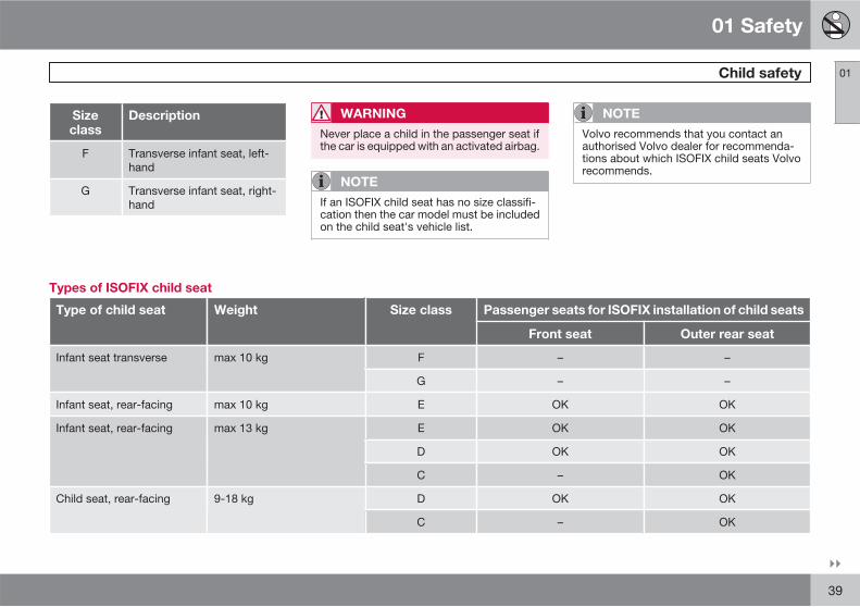
Size classes
Child seats are in different sizes – cars are indifferent sizes. This means that not all childseats are suitable for all seats in all car models.
Consequently, there is a size classification forchild seats using the ISOFIX fixture system inorder to assist users in choosing the correctchild seat (see the following table).
Sizeclass
Description
A Full size, front-facing childseat
B Reduced size (alt. 1), front-facing child seat
B1 Reduced size (alt.2), front-facing child seat
C Full size, rear-facing childseat
D Reduced size, rear-facingchild seat
E Rear-facing infant seat
01 Safety
Child safety 01
��
39
Sizeclass
Description
F Transverse infant seat, left-hand
G Transverse infant seat, right-hand
WARNING
Never place a child in the passenger seat ifthe car is equipped with an activated airbag.
NOTE
If an ISOFIX child seat has no size classifi-cation then the car model must be includedon the child seat's vehicle list.
NOTE
Volvo recommends that you contact anauthorised Volvo dealer for recommenda-tions about which ISOFIX child seats Volvorecommends.
Types of ISOFIX child seat
Type of child seat Weight Size class Passenger seats for ISOFIX installation of child seats
Front seat Outer rear seat
Infant seat transverse max 10 kg F – –
G – –
Infant seat, rear-facing max 10 kg E OK OK
Infant seat, rear-facing max 13 kg E OK OK
D OK OK
C – OK
Child seat, rear-facing 9-18 kg D OK OK
C – OK

01 Safety
Child safety 01
40
Type of child seat Weight Size class Passenger seats for ISOFIX installation of child seats
Front seat Outer rear seat
Front-facing child seat 9-18 kg B OKA OKA
B1 OKA OKA
A OKA OKA
A Volvo recommends rear-facing child seats for this group.
Upper mounting points for child seats
The car is equipped with upper mountingpoints for certain front-facing child seats.These mounting points are located on the rearof the seat.
The upper mounting points are primarilyintended for use with front-facing child seats.
Volvo recommends that small children shouldsit in rear-facing child seats to as late an ageas possible.
NOTE
For cars with folding head restraints on theoutside seats the head restraints should befolded to facilitate the installation of thistype of child seat.
NOTE
For cars equipped with a cargo area coverover the cargo area, this must be removedbefore a child seat can be fitted in themounting points.
For detailed information on how the child seatshould be tensioned in the upper mounting
points, see the seat manufacturer's instruc-tions.
WARNING
The child seat's straps must always berouted under the rear head restraints beforebeing tensioned at the mounting point.

01 Safety
01
41

42 * Option/accessory, for more information, see Introduction.
Remote control key/key blade................................................................ 44Privacy locking*....................................................................................... 49Battery replacement, remote control key/PCC*...................................... 51Keyless drive*.......................................................................................... 53Locking/unlocking................................................................................... 56Child safety locks.................................................................................... 61Alarm*...................................................................................................... 62

LOCKS AND ALARM
02 Locks and alarm
Remote control key/key blade
02
44
General
The car is supplied with 2 remote control keysor PCCs (Personal Car Communicator). Theyare used to start the car and for locking andunlocking.
More remote control keys can be ordered – upto 6 can be programmed and used for the samecar.
The PCC has increased functionality com-pared with the remote control key. The contin-uation of this chapter describes the functionsavailable in both the PCC and the remote con-trol key.
WARNING
If there are children in the car:
Always remember to switch off the powersupply to power windows and sunroof byremoving the remote control key if the driverleaves the car.
Loss of a remote control key
If you lose a remote control key then new onescan be ordered at a workshop - an authorisedVolvo workshop is recommended. The remain-ing remote control keys must then be taken tothe workshop. The code of the missing remote
control key must be erased from the system asa theft prevention measure.
The current number of keys registered to thecar can be checked under Car settings Car
Key memory Number of keys. For adescription of the menu system, seepage 130.
Key memory1 – door mirrors and driver's
seat
The settings are automatically connected toeach respective remote control key, see pages77 and 97 .
The function can be activated/deactivatedunder Car settings Car Key memory
Seat & mirror positions.
For a description of the menu system, seepage 130.
For cars with Keyless drive system, seepage 53.
Indicator for locking/unlocking
When the car is locked or unlocked using theremote control key, the direction indicatorsconfirm that locking/unlocking was correctlyperformed.
• Locking - one flash
• Unlocking - two flashes.
After locking the indication is only given if alllocks have been activated once the doors havebeen closed.
Selecting the function
The function can be activated/deactivatedunder Car settings Light settings Lock
confirmation light and Car settings Light
settings Unlock confirmation light.
For a description of the menu system, seepage 130.
Immobiliser
Each remote control key has a unique code.The car can only be driven with the correctremote control key with the correct code.
The following error messages in the combinedinstrument panel's information display are rela-ted to the electronic immobiliser:
1 Only in combination with power driver's seat and power mirrors.

02 Locks and alarm
Remote control key/key blade
02
��
* Option/accessory, for more information, see Introduction. 45
Message Specification
Key error Try again Error reading theremote control keyduring starting -Remove the key, re-insert it and try tostart again.
Car key not found
(Only applies to Key-less drive with PCC.)
Error reading thePCC during starting- Try to start again.
If the error persists:Press the remotecontrol key into theignition switch andtry to start again.
Immobiliser Try
start again
Error in immobilisersystem during star-ting. If the fault per-sists the recommen-dation is to contactan authorised Volvoworkshop.
For starting the car, see page 107.
Functions
G02
1078
Remote control key.
Locking
Unlocking
Approach light duration
Tailgate
Panic function
G02
1079
PCC* - Personal Car Communicator.
Information
Function buttons
Locking – Locks the doors and tailgatewhile the alarm is activated.
Press and hold (at least 2 seconds) to close allthe windows and sunroof* simultaneously.
WARNING
If the sunroof and windows are closed usingthe remote control key, check that no one isin danger of getting hands caught.
Unlocking – Unlocks the doors and tail-gate while the alarm is deactivated.

02 Locks and alarm
Remote control key/key blade
02
46 * Option/accessory, for more information, see Introduction.
Press and hold (at least 4 seconds) to open allwindows simultaneously.
The function can be changed from unlockingall doors simultaneously, to unlocking the driv-er's door only with one press of the button and,after a further press of the button - within 10seconds - unlocking the remaining doors.
The function can be changed in the menu sys-tem under Car settings Lock settings
Doors unlock with both the alternatives All
doors and Driver door, then all. For adescription of the menu system, seepage 130.
Approach light duration – Used to switchon the car's lighting at a distance. For moreinformation, see page 87.
Tailgate - Unlocks and disarms the alarmfor the tailgate only. On cars with power tail-gate* the tailgate is opened after the button iskept depressed. For more information, seepage 58.
Panic function – Used to attract attentionin an emergency.
Press and hold the button for at least 3 sec-onds or press it twice within 3 seconds to acti-vate the direction indicators and the horn.
The function can be turned off with the samebutton once it has been active for at least
5 seconds. Otherwise the function switches offautomatically after 2 minutes and 45 seconds.
Range
The remote control key's functions have arange of about 20 m from the car.
If the car does not verify a button being pressed- move closer and try again.
NOTE
The remote control key functions can bedisrupted by surrounding radio waves,buildings, topographical conditions etc. Thecar can always be locked/unlocked usingthe key blade, see page 47.
Unique functions PCC*
G02
1080
PCC* - Personal Car Communicator.
Information button
Indicator lamps
Using the information button enables access tocertain information from the car via the indica-tor lamps.
Using the information button
� Press the information button .
> All indicator lamps flash for approxi-mately 7 seconds and the light travelsaround on the PCC. This indicates thatinformation from the car has been read.
If any of the other buttons are pressedduring this time then the reading is inter-rupted.

02 Locks and alarm
Remote control key/key blade
02
��
47
NOTE
If none of the indicator lamps illumi-nates with repeated use of the informationbutton and in different locations (as well asafter 7 seconds and after the light has trav-elled around on the PCC), contact a work-shop - an authorised Volvo workshop is rec-ommended.
Indicator lamps display information in accord-ance with the following illustration:
Green continuous light – the car is locked.
Yellow continuous light – the car isunlocked.
Red continuous light – the alarm has beentriggered since the car was locked.
Red light flashing alternately in both indi-cator lamps – The alarm was triggered lessthan 5 minutes ago.
Range PCC
The PCC's range for locking, unlocking andtailgate is about 20 m from the car, for otherfunctions up to about 100 m.
If the car does not verify a button being pressed- move closer and try again.
NOTE
The information button functions can bedisrupted by surrounding radio waves,buildings, topographical conditions etc.
Out of PCC range
If the PCC is too far away from the car for theinformation to be read then the status the carwas last left in is shown, without the light trav-elling around on the PCC.
If several PCCs are used for the car then it isonly the PCC last used for locking/unlockingthat shows correct status.
NOTE
If no indicator lamps illuminate whenthe information button is used within rangethen this may be because the last commu-nication between the PCC and the car wasdisrupted by surrounding radio waves,buildings, topographical conditions etc.
Detachable key blade
A remote control key contains a detachablekey blade of metal with which some functionscan be activated and some operations carriedout.
The key blade's unique code is provided byauthorised Volvo workshops, which are rec-ommended when ordering new key blades.
Key blade functions
Using the remote control key's detachable keyblade:
• the driver's door can be opened manuallyif central locking cannot be activated withthe remote control key, see page 54.
• the rear doors' mechanical child safetylocks can be activated/deactivated, seepage 61.
02 Locks and alarm
Remote control key/key blade
02
48 * Option/accessory, for more information, see Introduction.
• access to the glovebox and cargo area(privacy locking*) can be blocked, seepage 49.
• the airbag for front passenger seat(PACOS)* can be activated/deactivated,see page 22.
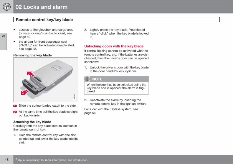
Removing the key blade
G02
1082
Slide the spring-loaded catch to the side.
At the same time pull the key blade straightout backwards.
Attaching the key blade
Carefully refit the key blade into its location inthe remote control key.
1. Hold the remote control key with the slotpointed up and lower the key blade into itsslot.
2. Lightly press the key blade. You shouldhear a "click" when the key blade is lockedin.
Unlocking doors with the key blade
If central locking cannot be activated with theremote control key, e.g. if the batteries are dis-charged, then the driver's door can be openedas follows:
1. Unlock the driver's door with the key bladein the door handle's lock cylinder.
NOTE
When the door has been unlocked using thekey blade and is opened, the alarm is trig-gered.
2. Deactivate the alarm by inserting theremote control key in the ignition switch.
For a car with the Keyless system, seepage 54.
02 Locks and alarm
Privacy locking*
02
��
* Option/accessory, for more information, see Introduction. 49
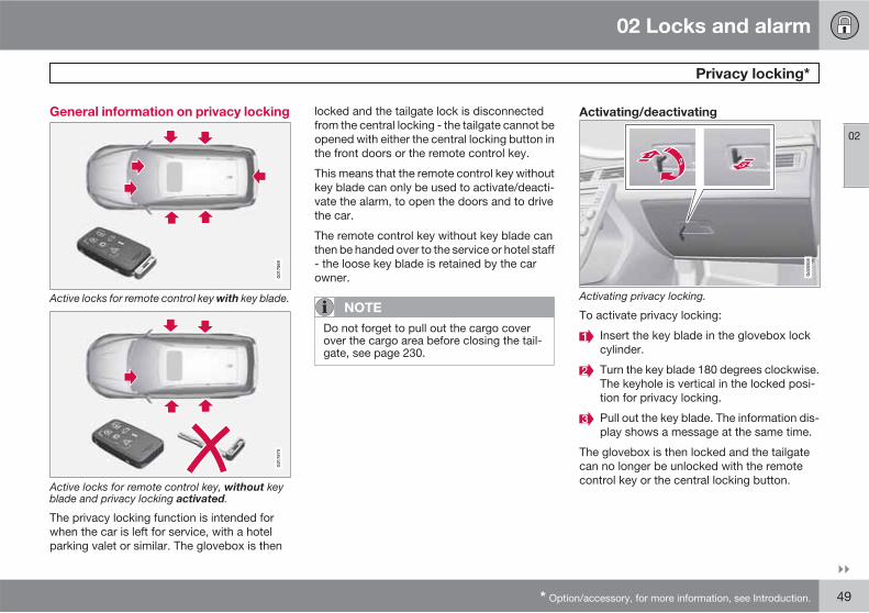
General information on privacy locking
G01
7869
Active locks for remote control key with key blade.
G01
7870
Active locks for remote control key, without keyblade and privacy locking activated.
The privacy locking function is intended forwhen the car is left for service, with a hotelparking valet or similar. The glovebox is then
locked and the tailgate lock is disconnectedfrom the central locking - the tailgate cannot beopened with either the central locking button inthe front doors or the remote control key.
This means that the remote control key withoutkey blade can only be used to activate/deacti-vate the alarm, to open the doors and to drivethe car.
The remote control key without key blade canthen be handed over to the service or hotel staff- the loose key blade is retained by the carowner.
NOTE
Do not forget to pull out the cargo coverover the cargo area before closing the tail-gate, see page 230.
Activating/deactivating
G02
0508
Activating privacy locking.
To activate privacy locking:
Insert the key blade in the glovebox lockcylinder.
Turn the key blade 180 degrees clockwise.The keyhole is vertical in the locked posi-tion for privacy locking.
Pull out the key blade. The information dis-play shows a message at the same time.
The glovebox is then locked and the tailgatecan no longer be unlocked with the remotecontrol key or the central locking button.

02 Locks and alarm
Privacy locking*
02
50 * Option/accessory, for more information, see Introduction.
NOTE
Do not reinsert the key blade into the remotecontrol key but keep it in a safe placeinstead.
• Deactivation takes place in reverse order.
For information on locking the glovebox only,see page 57.

02 Locks and alarm
Battery replacement, remote control key/PCC*
02
��
* Option/accessory, for more information, see Introduction. 51
Replacing the battery
The batteries should be replaced if:
• the information symbol is illuminated andthe display shows Replace car key
battery
and/or
• the locks repeatedly do not react to signalsfrom the remote control key within20 metres from the car.
Opening
Slide the spring-loaded catch to theside.
At the same time pull the key bladestraight out backwards.
Insert a 3 mm slot screwdriver in thehole behind the spring-loaded catch andgently prize the remote control key up.
NOTE
Turn the remote control key over with thebuttons facing up, this is to avoid the bat-teries falling out when it is opened.
IMPORTANT
Avoid touching the battery and its terminalswith your fingers, as this could damage theirfunctionality.
Battery replacement
Closely study how the battery/batteries aresecured on the inside of the cover, withregard to their (+) and (–) sides.
Remove control key (1 battery)
1. Carefully prize out the battery.2. Install a new one with the (+) side down.
PCC* (2 batteries)
1. Carefully prize out the batteries.2. First install one new one with the (+) side
up.3. Position the white plastic tab in between
and finally install a second new battery withthe (+) side down.
Battery type
Use batteries with the designation CR2430, 3V- one in the remote control key and two in thePCC.
Assembly
1. Press the remote control key together.
2. Hold the remote control key with the slotpointed up and lower the key blade into itsslot.
3. Lightly press the key blade. You shouldhear a "click" when the key blade is lockedin.

02 Locks and alarm
Battery replacement, remote control key/PCC*
02
52 * Option/accessory, for more information, see Introduction.
IMPORTANT
Make sure that you dispose of old batteriesin an environmentally-friendly way.
02 Locks and alarm
Keyless drive*
02
��
* Option/accessory, for more information, see Introduction. 53
Keyless lock and ignition system (only
PCC1)
General
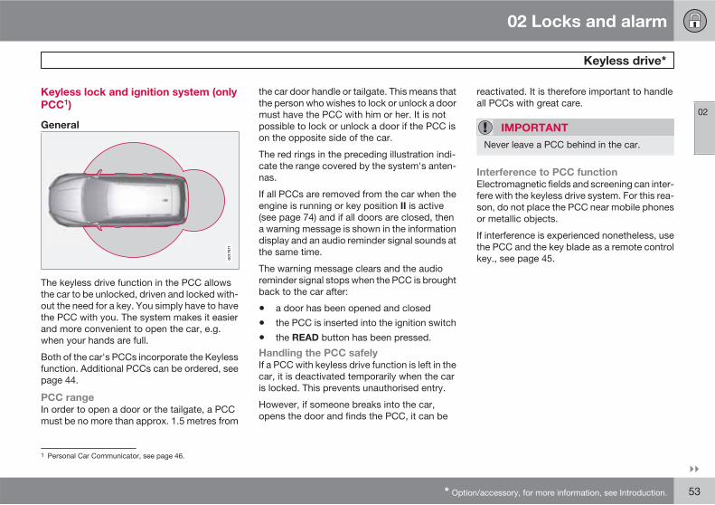
The keyless drive function in the PCC allowsthe car to be unlocked, driven and locked with-out the need for a key. You simply have to havethe PCC with you. The system makes it easierand more convenient to open the car, e.g.when your hands are full.
Both of the car's PCCs incorporate the Keylessfunction. Additional PCCs can be ordered, seepage 44.
PCC range
In order to open a door or the tailgate, a PCCmust be no more than approx. 1.5 metres from
the car door handle or tailgate. This means thatthe person who wishes to lock or unlock a doormust have the PCC with him or her. It is notpossible to lock or unlock a door if the PCC ison the opposite side of the car.
The red rings in the preceding illustration indi-cate the range covered by the system's anten-nas.
If all PCCs are removed from the car when theengine is running or key position II is active(see page 74) and if all doors are closed, thena warning message is shown in the informationdisplay and an audio reminder signal sounds atthe same time.
The warning message clears and the audioreminder signal stops when the PCC is broughtback to the car after:
• a door has been opened and closed
• the PCC is inserted into the ignition switch
• the READ button has been pressed.
Handling the PCC safely
If a PCC with keyless drive function is left in thecar, it is deactivated temporarily when the caris locked. This prevents unauthorised entry.
However, if someone breaks into the car,opens the door and finds the PCC, it can be
reactivated. It is therefore important to handleall PCCs with great care.
IMPORTANT
Never leave a PCC behind in the car.
Interference to PCC function
Electromagnetic fields and screening can inter-fere with the keyless drive system. For this rea-son, do not place the PCC near mobile phonesor metallic objects.
If interference is experienced nonetheless, usethe PCC and the key blade as a remote controlkey., see page 45.
1 Personal Car Communicator, see page 46.
02 Locks and alarm
Keyless drive*
02
54 * Option/accessory, for more information, see Introduction.
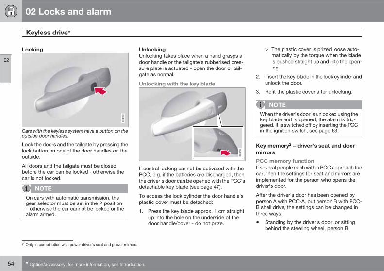
Locking
Cars with the keyless system have a button on theoutside door handles.
Lock the doors and the tailgate by pressing thelock button on one of the door handles on theoutside.
All doors and the tailgate must be closedbefore the car can be locked - otherwise thecar is not locked.
NOTE
On cars with automatic transmission, thegear selector must be set in the P position– otherwise the car cannot be locked or thealarm armed.
Unlocking
Unlocking takes place when a hand grasps adoor handle or the tailgate's rubberised pres-sure plate is actuated - open the door or tail-gate as normal.
Unlocking with the key blade
If central locking cannot be activated with thePCC, e.g. if the batteries are discharged, thenthe driver's door can be opened with the PCC'sdetachable key blade (see page 47).
To access the lock cylinder the door handle'splastic cover must be detached:
1. Press the key blade approx. 1 cm straightup into the hole on the underside of thedoor handle/cover - do not prize.
> The plastic cover is prized loose auto-matically by the torque when the bladeis pushed straight up and into the open-ing.
2. Insert the key blade in the lock cylinder andunlock the door.
3. Refit the plastic cover after unlocking.
NOTE
When the driver's door is unlocked using thekey blade and is opened, the alarm is trig-gered. It is switched off by inserting the PCCin the ignition switch, see page 63.
Key memory2 – driver's seat and door
mirrors
PCC memory function
If several people each with a PCC approach thecar, then the settings for seat and mirrors areimplemented for the person who opens thedriver's door.
After the driver's door has been opened byperson A with PCC-A, but person B with PCC-B shall drive, the settings can be changed inthree ways:
• Standing by the driver's door, or sittingbehind the steering wheel, person B
2 Only in combination with power driver's seat and power mirrors.
02 Locks and alarm
Keyless drive*
02
* Option/accessory, for more information, see Introduction. 55
presses their PCC's unlock button, seepage 45.
• Select one of three possible memories forseat adjustment with seat button 1-3, seepage 77.
• Adjust seat and mirrors manually, seepage 77 and 97.
Lock settings
The Keyless function can be adapted by indi-cating in the menu system which doors shall beunlocked, under Car settings Lock
settings Keyless entry.
For a description of the menu system, seepage 130.
Antenna location
G02
1179
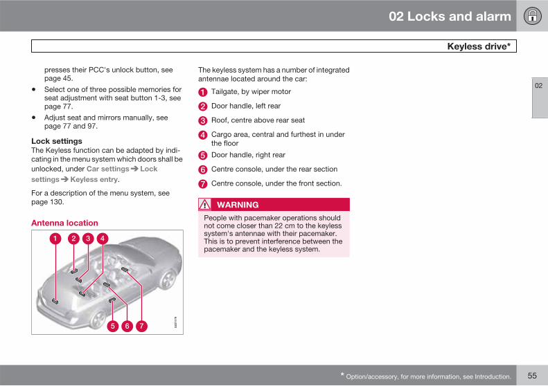
The keyless system has a number of integratedantennae located around the car:
Tailgate, by wiper motor
Door handle, left rear
Roof, centre above rear seat
Cargo area, central and furthest in underthe floor
Door handle, right rear
Centre console, under the rear section
Centre console, under the front section.
WARNING
People with pacemaker operations shouldnot come closer than 22 cm to the keylesssystem's antennae with their pacemaker.This is to prevent interference between thepacemaker and the keyless system.

02 Locks and alarm
Locking/unlocking
02
56 * Option/accessory, for more information, see Introduction.
From the outside
The remote control key can lock/unlock alldoors and the tailgate simultaneously. Differentsequences for unlocking can be selected, seeUnlocking with the remote control key, page45.
If it is not possible to lock/unlock with theremote control key, the battery may be dis-charged - lock or unlock the driver's door withthe detachable key blade, see page 47.
WARNING
Be aware that there is a risk that you can belocked in the car if it is locked from the out-side.
Automatic relocking
If none of the doors or the tailgate is openedwithin 2 minutes of unlocking, all are lockedagain automatically. This function reduces therisk that the car is left unlocked unintentionally.(For cars with alarm, see page 62.)
From the inside
Central locking
Central locking.
All of the doors and the tailgate can be lockedor unlocked simultaneously using the centrallocking button on either front door.
• Press one side of the button to lock -the other side to unlock.
Unlocking
A door can be unlocked from the inside in twodifferent ways:
• Press the central locking button .
Press and hold (at least 4 seconds) to alsoopen all the side windows* simultaneously.
• Pull the door handle once and release - thedoor is unlocked. Pull the door handleagain to open the door.
Locking
• Press the central locking button afterthe front doors have been closed.
Press and hold (at least 2 seconds) to alsoclose all the side windows and the sunroof*simultaneously.
All doors can also be individually locked man-ually with their lock buttons - the door in ques-tion must then be closed.
Global opening
Press and hold the central locking button (at least 4 seconds) to also open all the win-dows simultaneously - for example, to quicklyventilate the passenger compartment duringhot weather.
Automatic locking
The doors and tailgate are locked automati-cally when the car starts to move.
The function can be activated/deactivatedunder Car settings Lock settings
Doors automatic lock. (For a description ofthe menu system, see page 130.)

02 Locks and alarm
Locking/unlocking
02
��
* Option/accessory, for more information, see Introduction. 57
Glovebox
G02
0548
The glovebox can only be locked/unlockedusing the remote control key's detachable keyblade. (For information on the key blade, seepage 47).
Locking the glovebox:
Insert the key blade in the glovebox lockcylinder.
Turn the key blade 90 degrees clockwise.The keyhole is horizontal in the lockedposition.
Pull out the key blade.
• Unlock by carrying this out in reverseorder.
For information on privacy locking, seepage 49.
Tailgate
Unlocking with the remote control key
The alarm for the tailgate can be disarmed* andthe tailgate unlocked on its own by using theremote control key's button.
If the car is equipped with an alarm* the alarmindicator on the instrument panel stops toshow that alarm for the whole of the car is notarmed. The alarm's level and movement sen-sors and the sensors for opening the tailgateare disconnected.
The doors remain locked and armed.
• The tailgate is unlocked, but remainsclosed - press lightly on the rubberisedpressure plate under the outer handle andlift the tailgate.
If the tailgate is not opened within 2 minutesthen it is relocked and the alarm is re-armed.
Unlocking the car from inside
To unlock the tailgate:
� Press the lighting panel button (1).> The tailgate is unlocked and can be
opened within 2 minutes (if the car islocked from the inside).
Locking with the remote control key
� Press the remote control key's button forlocking, , see page 45.
> If the car is equipped with an alarm* thealarm indicator on the instrument panelstarts to flash, which means that thealarm is armed.
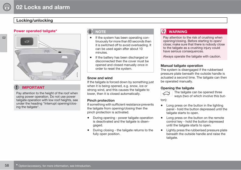
02 Locks and alarm
Locking/unlocking
02
58 * Option/accessory, for more information, see Introduction.
Power operated tailgate*
G01
7876
IMPORTANT
Pay attention to the height of the roof whenusing power operation. Do not use powertailgate operation with low roof heights, seeunder the heading "Interrupt opening/clos-ing the tailgate".
NOTE
• If the system has been operating con-tinuously for more than 60 seconds thenit is switched off to avoid overloading. Itcan be used again after about 10minutes.
• If the battery has been discharged ordisconnected then the cover must beopened and closed manually once inorder to reset the system.
Snow and wind
If the tailgate is forced down by something justwhen it is being opened, e.g. snow, ice orstrong wind, and this causes the tailgate tolower, then it is closed automatically.
Pinch protection
If something with sufficient resistance preventsthe tailgate from opening/closing then thepinch protection is activated.
• During opening - power tailgate operationis deactivated and the tailgate is disen-gaged.
• During closing - the tailgate returns to thefully open position.
WARNING
Pay attention to the risk of crushing whenopening/closing. Before starting to open/close; make sure that there is nobody closeto the tailgate as a crushing injury couldhave serious consequences.
Always operate the tailgate with caution.
Manual tailgate operation
The system is disengaged if the rubberisedpressure plate beneath the outside handle isactuated a second time. The tailgate can thenbe operated manually.
Opening the tailgate
The tailgate can be opened threeways (two of which involve this but-
ton):
• Long press on the button in the lightingpanel - hold the button depressed until thetailgate starts to open.
• Long press on the button on the remotecontrol key - hold the button depresseduntil the tailgate starts to open.
• Lightly press the rubberised pressure platebeneath the outside handle and raise thetailgate.
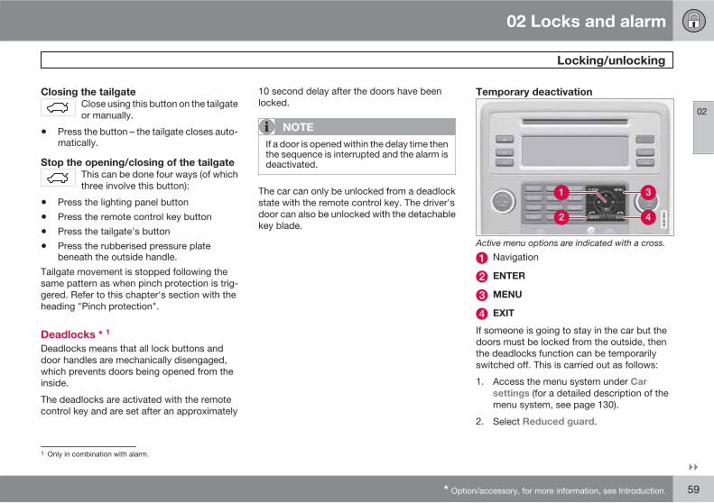
02 Locks and alarm
Locking/unlocking
02
��
* Option/accessory, for more information, see Introduction. 59
Closing the tailgate
Close using this button on the tailgateor manually.
• Press the button – the tailgate closes auto-matically.
Stop the opening/closing of the tailgate
This can be done four ways (of whichthree involve this button):
• Press the lighting panel button
• Press the remote control key button
• Press the tailgate's button
• Press the rubberised pressure platebeneath the outside handle.
Tailgate movement is stopped following thesame pattern as when pinch protection is trig-gered. Refer to this chapter's section with theheading "Pinch protection".
Deadlocks * 1
Deadlocks means that all lock buttons anddoor handles are mechanically disengaged,which prevents doors being opened from theinside.
The deadlocks are activated with the remotecontrol key and are set after an approximately
10 second delay after the doors have beenlocked.
NOTE
If a door is opened within the delay time thenthe sequence is interrupted and the alarm isdeactivated.
The car can only be unlocked from a deadlockstate with the remote control key. The driver'sdoor can also be unlocked with the detachablekey blade.
Temporary deactivation
Active menu options are indicated with a cross.
Navigation
ENTER
MENU
EXIT
If someone is going to stay in the car but thedoors must be locked from the outside, thenthe deadlocks function can be temporarilyswitched off. This is carried out as follows:
1. Access the menu system under Car
settings (for a detailed description of themenu system, see page 130).
2. Select Reduced guard.
1 Only in combination with alarm.
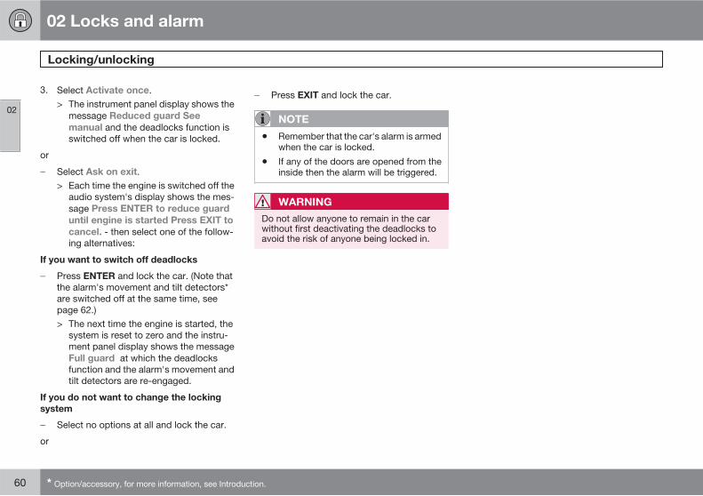
02 Locks and alarm
Locking/unlocking
02
60 * Option/accessory, for more information, see Introduction.
3. Select Activate once.> The instrument panel display shows the
message Reduced guard See
manual and the deadlocks function isswitched off when the car is locked.
or
� Select Ask on exit.> Each time the engine is switched off the
audio system's display shows the mes-sage Press ENTER to reduce guard
until engine is started Press EXIT to
cancel. - then select one of the follow-ing alternatives:
If you want to switch off deadlocks
� Press ENTER and lock the car. (Note thatthe alarm's movement and tilt detectors*are switched off at the same time, seepage 62.)> The next time the engine is started, the
system is reset to zero and the instru-ment panel display shows the messageFull guard at which the deadlocksfunction and the alarm's movement andtilt detectors are re-engaged.
If you do not want to change the locking
system
� Select no options at all and lock the car.
or
� Press EXIT and lock the car.
NOTE
• Remember that the car's alarm is armedwhen the car is locked.
• If any of the doors are opened from theinside then the alarm will be triggered.
WARNING
Do not allow anyone to remain in the carwithout first deactivating the deadlocks toavoid the risk of anyone being locked in.
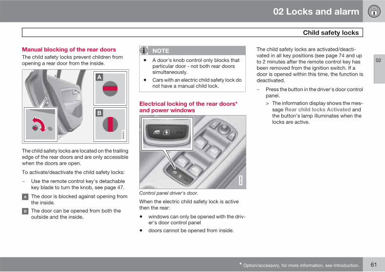
02 Locks and alarm
Child safety locks
02
* Option/accessory, for more information, see Introduction. 61
Manual blocking of the rear doors
The child safety locks prevent children fromopening a rear door from the inside.
G02
1077
The child safety locks are located on the trailingedge of the rear doors and are only accessiblewhen the doors are open.
To activate/deactivate the child safety locks:
� Use the remote control key's detachablekey blade to turn the knob, see page 47.
The door is blocked against opening fromthe inside.
The door can be opened from both theoutside and the inside.
NOTE
• A door's knob control only blocks thatparticular door - not both rear doorssimultaneously.
• Cars with an electric child safety lock donot have a manual child lock.
Electrical locking of the rear doors*and power windows
Control panel driver's door.
When the electric child safety lock is activethen the rear:
• windows can only be opened with the driv-er's door control panel
• doors cannot be opened from inside.
The child safety locks are activated/deacti-vated in all key positions (see page 74 and upto 2 minutes after the remote control key hasbeen removed from the ignition switch. If adoor is opened within this time, the function isdeactivated.
� Press the button in the driver's door controlpanel.> The information display shows the mes-
sage Rear child locks Activated andthe button's lamp illuminates when thelocks are active.

02 Locks and alarm
Alarm*
02
62 * Option/accessory, for more information, see Introduction.
General
Activated alarm is triggered if:
• a door, the bonnet or the tailgate is opened
• a movement is detected in the passengercompartment (if fitted with a movementdetector*)
• the car is raised or towed away (if fittedwith a tilt detector*)
• the battery's cable is disconnected
• the siren is disconnected.
If there is a fault in the alarm system, the infor-mation display shows a message. In whichcase, contact a workshop - an authorisedVolvo workshop is recommended.
NOTE
The movement sensors trigger an alarm inthe event of movement in the passengercompartment - air currents are also regis-tered. For this reason the alarm is triggeredif the car is left with a window or the sunroofopen or if the passenger compartmentheater is used.
To avoid this: Close the window/sunroofwhen leaving the car. If the car's integratedpassenger compartment heater (or a porta-ble electric heater) shall be used - direct theairflow from the air vents so that they are notpointing upwards in the passenger com-partment.
NOTE
Do not attempt to repair or modify alarmsystem components. All such attemptscould affect the terms of insurance.
Alarm indicator
A red LED on the instrument panel indicatesthe alarm system's status:
• LED not lit – Alarm not armed
• The LED flashes once every other second– Alarm is armed
• The LED flashes rapidly after disarming thealarm (and until the remote control key isinserted in the ignition switch and key posi-tion I is selected) – Alarm has been trig-gered.
Arming the alarm
� Press the remote control key lock button.
Disarming the alarm
� Press the remote control key unlock but-ton.
Deactivating a triggered alarm
� Press the remote control key unlock buttonor insert the remote control key in the igni-tion switch.
Other alarm functions
Automatic re-arming of the alarm
This function prevents the car being left withalarm disarmed unintentionally.
If the car is unlocked with the remote controlkey (and the alarm is disarmed) but none of thedoors or the tailgate is opened within2 minutes, then the alarm is automatically re-armed. The car is relocked at the same time.
Alarm signals
When the alarm is triggered, the following hap-pens:
• A siren sounds for 30 seconds or until thealarm is switched off. The siren has its own
02 Locks and alarm
Alarm*
02
* Option/accessory, for more information, see Introduction. 63
battery which works independently of thecar battery.
• The direction indicators flash for 5 minutesor until the alarm is switched off.
Remote control key not working
If the alarm cannot be switched off with theremote control key, e.g. if the key's battery isdischarged, the car can be disarmed and theengine started as follows:
1. Open the driver's door with the key blade.> The alarm is triggered, the alarm indica-
tor flashes rapidly and the siren sounds.
2. Insert the remote control key in the ignitionswitch.> The alarm is deactivated and the alarm
indicator goes out.
3. Start the engine.
Reduced alarm level
To avoid accidental triggering of the alarm -e.g. if a dog is left in the car or during transporton a car train or a car ferry - the movement andtilt sensors can be temporarily deactivated.
The procedure is the same as with the tempo-rary disengaging of deadlocks, see page 59.
Testing the alarm system
Testing the movement detector in the
passenger compartment
1. Close all windows. Remain in the car.
2. Arm the alarm, see page 62.
3. Wait 15 seconds.
4. Trigger the alarm by moving your arms for-ward and back at backrest height.> A siren sounds and all direction indica-
tors flash.
5. Deactivate the alarm by unlocking the carwith the remote control key.
Testing the alarm sensors in the doors
1. Arm the alarm, see page 62.
2. Wait 15 seconds.
3. Unlock the driver's door using the keyblade.
4. Open the driver's door.> A siren sounds and all direction indica-
tors flash.
5. Deactivate the alarm by unlocking the carwith the remote control key.
Testing the alarm sensors for the bonnet
1. Sit in the car and deactivate the movementsensor, see the previous section Reducedalarm level.
2. Arm the alarm, see page 62. Remain in thecar and lock the doors with the button onthe remote control key.
3. Wait 15 seconds.
4. Open the bonnet with the handle under thedashboard.> A siren sounds and all direction indica-
tors flash.
5. Deactivate the alarm by unlocking the carwith the remote control key.

64 * Option/accessory, for more information, see Introduction.
Instruments and controls........................................................................ 66Key positions.......................................................................................... 74Seats....................................................................................................... 76Steering wheel........................................................................................ 81Lighting................................................................................................... 82Wipers and washing................................................................................ 92Windows, rearview and door mirrors...................................................... 95Compass*.............................................................................................. 100Power sunroof*..................................................................................... 101Alcoguard*............................................................................................ 103Starting the engine................................................................................ 107Starting the engine – Flexifuel............................................................... 109Starting the engine – external battery................................................... 111Gearboxes............................................................................................. 112All-wheel drive – AWD*......................................................................... 117Foot brake............................................................................................. 118Hill Descent Control (HDC)................................................................... 120Parking brake........................................................................................ 122
HomeLink *.......................................................................................... 125

YOUR DRIVING ENVIRONMENT

03 Your driving environment
Instruments and controls
03
66
Instrument overview
Left-hand drive.

03 Your driving environment
Instruments and controls
03
��
* Option/accessory, for more information, see Introduction. 67
Function Page
Menus and messages,direction indicators,main/dipped beam, tripcomputer
82,85, 134,166
Cruise control 171, 173
Horn, airbags 20, 81
Combined instrumentpanel
69, 73
Menu, audio and phonecontrol
130,148, 205
Ignition switch 74
Start/stop button 107
Hazard warning flashers 85
Door handle –
Control panel 56, 61,95, 97
Menu control and audiosystem
130, 149
Climate control, ECC 139
Function Page
Gear selector 112
Controls for active chas-sis (Four-C)*
170
Wipers and washing 92, 93
Steering wheel adjust-ment
81
Parking brake 122
Bonnet opener 256
Seat adjustment* 76
Headlamp control,opener for fuel filler flapand tailgate
57, 82,219

03 Your driving environment
Instruments and controls
03
68
Right-hand drive.
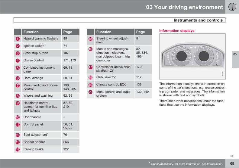
03 Your driving environment
Instruments and controls
03
��
* Option/accessory, for more information, see Introduction. 69
Function Page
Hazard warning flashers 85
Ignition switch 74
Start/stop button 107
Cruise control 171, 173
Combined instrumentpanel
69, 73
Horn, airbags 20, 81
Menu, audio and phonecontrol
130,148, 205
Wipers and washing 92, 93
Headlamp control,opener for fuel filler flapand tailgate
57, 82,219
Door handle –
Control panel 56, 61,95, 97
Seat adjustment* 76
Bonnet opener 256
Parking brake 122
Function Page
Steering wheel adjust-ment
81
Menus and messages,direction indicators,main/dipped beam, tripcomputer
82,85, 134,166
Controls for active chas-sis (Four-C)*
170
Gear selector 112
Climate control, ECC 139
Menu control and audiosystem
130, 149
Information displays
The information displays show information onsome of the car's functions, e.g. cruise control,trip computer and messages. The informationis shown with text and symbols.
There are further descriptions under the func-tions that use the information displays.

03 Your driving environment
Instruments and controls
03
70
Meters
Meters in the combined instrument panel.
Speedometer
Fuel gauge. See also Trip computer, page166, and Refuelling, page 219.
Tachometer. The meter indicates enginespeed in thousands of revolutions perminute (rpm).
Indicator, information and warningsymbols
Indicator and warning symbols.
Main beam and direction indicator symbol
Indicator and information symbols
Indicator and warning symbols1
Functionality check
All indicator and warning symbols illuminate inkey position II or when the engine is started.When the engine has started, all the symbolsshould go out except the parking brake sym-bol, which only goes out when the brake is dis-engaged.
If the engine does not start or if the functionalitycheck is carried out in key position II then all
symbols go out after 5 seconds except thesymbol for faults in the car's emissions systemand the symbol for low oil pressure.
Indicator and information symbols
Sym-bol
Specification
ABL fault
Emissions system
ABS fault
Rear fog lamp on
Stability system
Engine preheater (diesel)
Low level in fuel tank
Information, read display text
Main beam On
1 For certain engine variants, the symbol for low oil pressure is not used. Warnings are made via display text. For information on checking the oil level, see page 257.
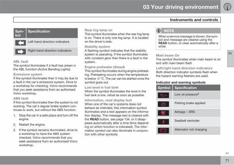
03 Your driving environment
Instruments and controls
03
��
71
Sym-bol
Specification
Left-hand direction indicators
Right-hand direction indicators
ABL fault
The symbol illuminates if a fault has arisen inthe ABL function (Active Bending Lights).
Emissions system
If the symbol illuminates then it may be due toa fault in the car's emissions system. Drive toa workshop for checking. Volvo recommendsthat you seek assistance from an authorisedVolvo workshop.
ABS fault
If this symbol illuminates then the system is notworking. The car's regular brake system con-tinues to work, but without the ABS function.
1. Stop the car in a safe place and turn off theengine.
2. Restart the engine.
3. If the symbol remains illuminated, drive toa workshop to have the ABS systemchecked. Volvo recommends that youseek assistance from an authorised Volvoworkshop.
Rear fog lamp on
This symbol illuminates when the rear fog lampis on. There is only one fog lamp. It is locatedon the driver's side.
Stability system
A flashing symbol indicates that the stabilitysystem is operating. If the symbol illuminateswith constant glow then there is a fault in thesystem.
Engine preheater (diesel)
This symbol illuminates during engine preheat-ing. Preheating occurs when the temperatureis below 2 °C. The car can be started once thesymbol goes out.
Low level in fuel tank
When the symbol illuminates the level in thefuel tank is low, refuel as soon as possible.
Information, read display text
When one of the car's systems does notbehave as intended, this information symbolilluminates and a text appears on the informa-tion display. The message text is cleared withthe READ button, see page 134, or it disap-pears automatically after a time (time depend-ing on which function is indicated). The infor-mation symbol can also illuminate in conjunc-tion with other symbols.
NOTE
When a service message is shown, the sym-bol and message are cleared using theREAD button, or clear automatically after awhile.
Main beam On
The symbol illuminates when main beam is onand with main beam flash
Left/right-hand direction indicators
Both direction indicator symbols flash whenthe hazard warning flashers are used.
Indicator and warning symbols
Symbol Specification
Low oil pressureA
Parking brake applied
Airbags – SRS
Seatbelt reminder
Alternator not charging
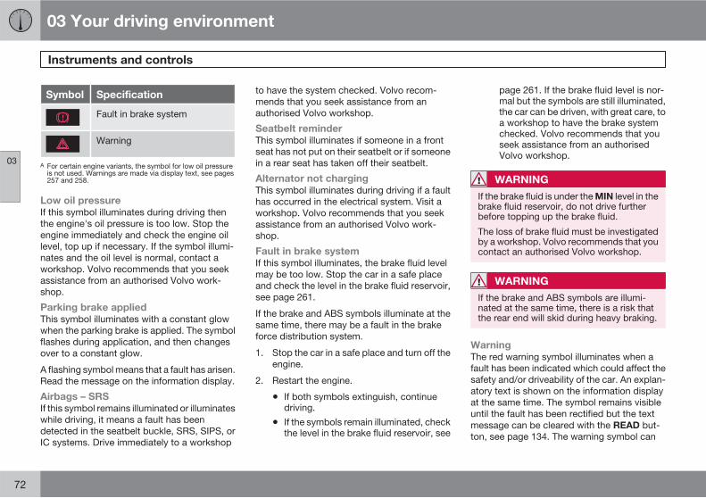
03 Your driving environment
Instruments and controls
03
72
Symbol Specification
Fault in brake system
Warning
A For certain engine variants, the symbol for low oil pressureis not used. Warnings are made via display text, see pages257 and 258.
Low oil pressure
If this symbol illuminates during driving thenthe engine's oil pressure is too low. Stop theengine immediately and check the engine oillevel, top up if necessary. If the symbol illumi-nates and the oil level is normal, contact aworkshop. Volvo recommends that you seekassistance from an authorised Volvo work-shop.
Parking brake applied
This symbol illuminates with a constant glowwhen the parking brake is applied. The symbolflashes during application, and then changesover to a constant glow.
A flashing symbol means that a fault has arisen.Read the message on the information display.
Airbags – SRS
If this symbol remains illuminated or illuminateswhile driving, it means a fault has beendetected in the seatbelt buckle, SRS, SIPS, orIC systems. Drive immediately to a workshop
to have the system checked. Volvo recom-mends that you seek assistance from anauthorised Volvo workshop.
Seatbelt reminder
This symbol illuminates if someone in a frontseat has not put on their seatbelt or if someonein a rear seat has taken off their seatbelt.
Alternator not charging
This symbol illuminates during driving if a faulthas occurred in the electrical system. Visit aworkshop. Volvo recommends that you seekassistance from an authorised Volvo work-shop.
Fault in brake system
If this symbol illuminates, the brake fluid levelmay be too low. Stop the car in a safe placeand check the level in the brake fluid reservoir,see page 261.
If the brake and ABS symbols illuminate at thesame time, there may be a fault in the brakeforce distribution system.
1. Stop the car in a safe place and turn off theengine.
2. Restart the engine.
• If both symbols extinguish, continuedriving.
• If the symbols remain illuminated, checkthe level in the brake fluid reservoir, see
page 261. If the brake fluid level is nor-mal but the symbols are still illuminated,the car can be driven, with great care, toa workshop to have the brake systemchecked. Volvo recommends that youseek assistance from an authorisedVolvo workshop.
WARNING
If the brake fluid is under the MIN level in thebrake fluid reservoir, do not drive furtherbefore topping up the brake fluid.
The loss of brake fluid must be investigatedby a workshop. Volvo recommends that youcontact an authorised Volvo workshop.
WARNING
If the brake and ABS symbols are illumi-nated at the same time, there is a risk thatthe rear end will skid during heavy braking.
Warning
The red warning symbol illuminates when afault has been indicated which could affect thesafety and/or driveability of the car. An explan-atory text is shown on the information displayat the same time. The symbol remains visibleuntil the fault has been rectified but the textmessage can be cleared with the READ but-ton, see page 134. The warning symbol can
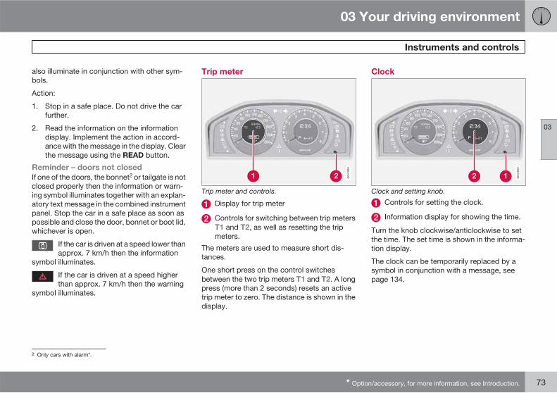
03 Your driving environment
Instruments and controls
03
* Option/accessory, for more information, see Introduction. 73
also illuminate in conjunction with other sym-bols.
Action:
1. Stop in a safe place. Do not drive the carfurther.
2. Read the information on the informationdisplay. Implement the action in accord-ance with the message in the display. Clearthe message using the READ button.
Reminder – doors not closed
If one of the doors, the bonnet2 or tailgate is notclosed properly then the information or warn-ing symbol illuminates together with an explan-atory text message in the combined instrumentpanel. Stop the car in a safe place as soon aspossible and close the door, bonnet or boot lid,whichever is open.
If the car is driven at a speed lower thanapprox. 7 km/h then the information
symbol illuminates.
If the car is driven at a speed higherthan approx. 7 km/h then the warning
symbol illuminates.
Trip meter
Trip meter and controls.
Display for trip meter
Controls for switching between trip metersT1 and T2, as well as resetting the tripmeters.
The meters are used to measure short dis-tances.
One short press on the control switchesbetween the two trip meters T1 and T2. A longpress (more than 2 seconds) resets an activetrip meter to zero. The distance is shown in thedisplay.
Clock
Clock and setting knob.
Controls for setting the clock.
Information display for showing the time.
Turn the knob clockwise/anticlockwise to setthe time. The set time is shown in the informa-tion display.
The clock can be temporarily replaced by asymbol in conjunction with a message, seepage 134.
2 Only cars with alarm*.

03 Your driving environment
Key positions
03
74 * Option/accessory, for more information, see Introduction.
Insert and remove the remote controlkey
G02
1126
Ignition switch with inserted remote control key.
NOTE
For cars with keyless function*, seepage 53.
Insert the key
Hold the end of the remote control key with thedetachable key blade and insert the key in theignition switch. After a gentle press on the keyit is drawn into the lock.
IMPORTANT
Foreign objects in the ignition switch mayjeopardise the function or destroy the lock.
Do not press the remote control key incor-rectly turned - Hold the end with the detach-able key blade, see page 47.
Withdraw the key
The remote control key is ejected after a gentlepress on it. (Automatic gearbox* must be inposition P.)
Functions
The remote control key's 3 different key posi-tions can be reached without the need to startthe engine. The table shows the functionsavailable in each key position.
NOTE
To reach key position I or II without startingthe engine - do not depress the brake/clutch pedal when the following operationsare carried out.
Key position 0
Insert the remote control key in the ignitionswitch and gently press it - The key is drawninto the lock.
Key position I
With the remote control key inserted into theignition switch - Briefly press on START/STOP
ENGINE.
Key position II
With the remote control key inserted into theignition switch - Press on START/STOP
ENGINE for about 2 seconds.
Back to key position 0
To return to key position 0 from position I or II- Briefly press on START/STOP ENGINE.
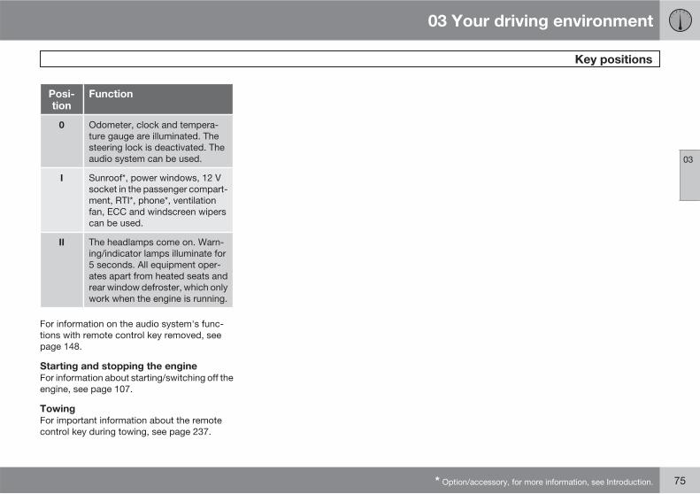
03 Your driving environment
Key positions
03
* Option/accessory, for more information, see Introduction. 75
Posi-tion
Function
0 Odometer, clock and tempera-ture gauge are illuminated. Thesteering lock is deactivated. Theaudio system can be used.
I Sunroof*, power windows, 12 Vsocket in the passenger compart-ment, RTI*, phone*, ventilationfan, ECC and windscreen wiperscan be used.
II The headlamps come on. Warn-ing/indicator lamps illuminate for5 seconds. All equipment oper-ates apart from heated seats andrear window defroster, which onlywork when the engine is running.
For information on the audio system's func-tions with remote control key removed, seepage 148.
Starting and stopping the engine
For information about starting/switching off theengine, see page 107.
Towing
For important information about the remotecontrol key during towing, see page 237.

03 Your driving environment
Seats
03
76 * Option/accessory, for more information, see Introduction.
Front seats
Lumbar support adjustment, turn thewheel1.
Forward/backward: lift the handle to adjustthe distance to the steering wheel and ped-als. Check that the seat is locked afterchanging position.
Raise/lower* front edge of seat cushion,pump up/down.
Adjust backrest rake, turn the wheel.
Raise/lower the seat, pump up/down.
Control panel for power seat*.
WARNING
Adjust the position of the driver's seatbefore setting off, never while driving. Makesure that the seat is in locked position inorder to avoid personal injury in the event ofsudden braking or an accident.
Lowering the front seat backrest
The passenger seat backrest can be foldedforward to make room for long loads.
Move the seat as far back/down as possi-ble.
Adjust the backrest to an upright position.
Lift the catches on the rear of the backrestand fold it forward.
4. Push the seat forward so that the headrestraint "locks" in under the glovebox.
Raising takes place in reverse order.
WARNING
Grasp the backrest and make sure that it isproperly locked after being folded up inorder to avoid personal injury in the event ofsudden braking or an accident.
1 Also applies to power seat.

03 Your driving environment
Seats
03
��
* Option/accessory, for more information, see Introduction. 77
Power seat*
Front edge of seat cushion up/down
Seat forward/backward and up/down
Backrest rake
The power front seats have overload protectionwhich is tripped if a seat is blocked by anobject. If this happens, go to key position I or0 and wait a short time before adjusting theseat again.
Only one movement (forward/back/up/down)can be made at a time.
Preparations
The seats can be adjusted for a certain timeafter unlocking the door with the remote con-
trol key without the key in the ignition switch.Seat adjustment is normally made in key posi-tion I and can always be made when the engineis running.
Seat with memory function*
Store setting
Memory button
Memory button
Memory button
Button for storing settings
1. Adjust the seat and the door mirrors.
2. Hold the button depressed to store set-tings while depressing one of the memorybuttons.
Using a stored setting
Hold one of the memory buttons depresseduntil the seat and the door mirrors stop. If yourelease the button then the movement of theseat will stop.
Key memory* in remote control key2
The positions of the driver's seat and the doormirrors3 are stored in the key memory when thecar is locked with the remote control key.
When the car is unlocked with the same remotecontrol key it was locked with and the driver's
2 For key memory for keyless drive, see page 54.3 Only if the car is equipped with power seat and retractable power door mirrors.

03 Your driving environment
Seats
03
78 * Option/accessory, for more information, see Introduction.
door is opened, the driver's seat and also thedoor mirrors automatically adopt the positionsstored in the key memory.
NOTE
The seat and the door mirrors do not moveif they are already set the relevant position.
It is also possible to use the key memory bypressing the unlock button on the remote con-trol key when the driver's door is open.
The key memory can be activated/deactivatedunder Car Key memory Seat & mirror
positions. For a description of the menu sys-tem, see page 130.
NOTE
The key memory in the two remote controlkeys and the seat's three memories arecompletely independent of each other.
Emergency stop
If the seat accidentally begins to move, pressone of the buttons to stop the seat.
Restarting to reach the seat position stored inthe key memory is performed by pressing theunlock button on the remote control key. Thedriver's door must then be open.
WARNING
Risk of crushing! Make sure that children donot play with the controls. Check that thereare no objects in front of, behind or underthe seat during adjustment. Ensure thatnone of the backseat passengers will betrapped.
Heated/ventilated seats*
For heated/ventilated seats, see page 140.
Rear seats
Head restraint, centre seat, rear
Adjust the head restraint according to passen-ger height so that the whole of the back of thehead is covered if possible. Slide it up asrequired.
To lower the head restraint again, the button(located in the centre between the backrestand head restraint, see illustration) must bepressed in while the head restraint is presseddown.
Manual lowering of the outer head
restraints, rear seat
Pull the locking handle closest to the headrestraint to fold the head restraint forward.
The head restraint is moved back manuallyuntil a "click" can be heard.

03 Your driving environment
Seats
03
��
* Option/accessory, for more information, see Introduction. 79
Lowering the rear seat backrest
IMPORTANT
There must be no objects on the rear seatwhen the backrest is to be folded down. Theseat belts must not be connected either.Otherwise there is a risk of damaging therear seat upholstery.
The triple-section backrest can be folded indifferent ways.
NOTE
The front seats may need to be pushed for-wards, and/or the backrests adjustedupwards, in order that the rear backrestscan be folded forward fully.
• The left-hand section can be folded sepa-rately.
• The centre section can be folded sepa-rately.
• The right-hand section can only be foldedtogether with the centre section.
• If the entire backrest is to be folded thenthe different sections should be foldedseparately.
If the centre backrest is being lowered -fold and adjust the centre backrest's headrestraint downwards, see page 78.
The outer head restraints are lowered auto-matically when the outer backrests arelowered. Pull up the backrest's lockinghandle while folding the backrest for-ward at the same time. A red indicator onthe lock catch shows that the backrestis no longer locked in place.
Raising takes place in reverse order.
NOTE
When the backrest has been raised, the redindicator should no longer be showing. If itis still showing then the backrest is notlocked in place.
WARNING
Check that the backrests and headrestraints in the rear seats are firmly lockedafter raising.
Electrical lowering of the rear seat's
outer head restraints*
03 Your driving environment
Seats
03
80
1. The remote control key must be in positionI or II.
2. Press the button to lower the rear outerhead restraints to improve rearward visi-bility.
WARNING
Do not lower the outer head restraints ifthere are any passengers using of the outerseats.
Move the head restraint back manually until aclick is heard.
WARNING
The head restraints must be in locked posi-tion after being raised.

03 Your driving environment
Steering wheel
03
* Option/accessory, for more information, see Introduction. 81
Adjusting
G02
1138
Adjusting the steering wheel.
Lever - releasing the steering wheel
Possible steering wheel positions
The steering wheel can be adjusted for bothheight and depth:
1. Pull the lever towards you to release thesteering wheel.
2. Adjust the steering wheel to the positionthat suits you.
3. Push back the lever to fix the steeringwheel in place. If the lever is stiff, press thesteering wheel lightly at the same time asyou push the lever back.
WARNING
Adjust and secure the steering wheel beforedriving.
With speed related power steering* the level ofsteering force can be adjusted, seepage 170.
Keypads*
Keypads in the steering wheel.
Cruise control, see page 171
Adaptive cruise control, see page 173
Audio and phone control, see page 148
Horn
Horn.
Press the centre of the steering wheel to signal.

03 Your driving environment
Lighting
03
82 * Option/accessory, for more information, see Introduction.
Light switches
G02
1141
Overview, light switches.
Thumbwheel for adjusting display andinstrument lighting
Rear fog lamp
Front fog lamps*
Light switches
Thumbwheel1 for headlamp levelling
Instrument lighting
Different display and instrument lighting isswitched on depending on key position, seepage 74.
The display lighting is automatically subduedin darkness - the sensitivity is set with thethumbwheel.
The intensity of the instrument lighting isadjusted with the thumbwheel.
Headlamp levelling
The load in the car changes the vertical align-ment of the headlamp beam, which could daz-zle oncoming motorists. Avoid this by adjustingthe height of the beam. Lower the beam if thecar is heavily laden.
1. Allow the engine to run or have the remotecontrol key in position I.
2. Roll the thumbwheel up/down to raise/lower beam alignment.
Cars with Xenon headlamps* have automaticheadlamp levelling and therefore do not havethe thumbwheel.
Main/dipped beam
G02
1142
Headlamp control and stalk switch.
Position for main beam flash
Position for main beam
1 Not available for cars equipped with Xenon headlamps*.

03 Your driving environment
Lighting
03
��
* Option/accessory, for more information, see Introduction. 83
Posi-tion
Specification
AutomaticA/deactivated dippedbeam. Only main beam flash.
Position/parking lamps
Dipped beam. Main beam andmain beam flash work in thisposition.
A Applies to certain markets.
NOTE
Main beam can only be activated in position.
Main beam flash
Move the stalk switch gently towards the steer-ing wheel to the position for main beam flash.Main beam comes on until the stalk switch isreleased.
Dipped beam
When the engine is started, dipped beam isactivated automatically2 if the headlamp con-trol is in position . If necessary, auto-matic dipped beam for this position can be
deactivated by a workshop. Volvo recom-mends that you contact an authorised Volvoworkshop.
In position dipped beam is always acti-vated automatically when the engine is runningor when the remote control key is in positionII.
Main beam
Main beam can only be activated when theheadlamp control is in position . Acti-vate/deactivate main beam by moving the stalkswitch towards the steering wheel to the endposition and release.
When main beam has been activated the sym-bol illuminates in the combined instru-ment panel.
Active Xenon headlamps - ABL*
Headlamp pattern with function deactivated (left)and activated (right) respectively.
If the car is equipped with active Xenon head-lamps (Active Bending Lights - ABL) the lightfrom the headlamps follows the steering wheelmovement in order to provide maximum light-ing in bends and junctions and so provideincreased safety.
The function is activated automatically whenthe car is started. In the event of a fault in thefunction the symbol illuminates in thecombined instrument panel at the same timeas the information display shows an explana-tory text and a further illuminated symbol.
2 Applies to certain markets.

03 Your driving environment
Lighting
03
84
Symbol Display Specifica-tion
Headlamp
failure
Service
required
The systemis disen-gaged. Visita workshopif the mes-sageremains.Volvo rec-ommendsthat youcontact anauthorisedVolvo work-shop.
The function is only active in twilight or dark-ness and only when the car is moving.
The function3 can be activated/deactivatedunder Car settings Light settings
Active bending lights. For a description of themenu system, see page 130.
For headlamp pattern adjustment, seepage 87.
Position/parking lamps
G02
1144
Headlamp control in position for position/parkinglamps.
Turn the headlamp control to the centre posi-tion (number plate lighting comes on at thesame time).
Rear position lamps also come on when thetailgate is opened in order to alert anybodybehind.
Brake lights
The brake light automatically comes on duringbraking. For information on the Emergencybrake lights and automatic hazard warningflashers, see page 118.
Front fog lamps
G02
1145
Button for front fog lamps.
The front fog lamps can be switched on alongwith main/dipped beam orposition/parking lamps.
The front fog lamps* can be switched on alongwith main/dipped beam orposition/parking lamps.
3 Activated on delivery from the factory.

03 Your driving environment
Lighting
03
��
85
Press the button for on/off. The light in the but-ton illuminates when the fog lamps are on.
NOTE
Regulations for using front fog lamps varybetween different countries.
Rear fog lamp
G02
1146
Button for rear fog lamp.
The rear fog lamp consists of one rear lamp andcan only be switched on in combination withmain/dipped beam or the front fog lamps.
Press the button for On/Off. The rear fog lampindicator symbol on the combinedinstrument panel and the light in the button illu-minate when the rear fog lamp is switched on.
The rear fog lamp is switched off automaticallywhen the engine is switched off.
NOTE
Regulations for using rear fog lamps varybetween different countries.
Hazard warning flashers
Button for hazard warning flashers.
Press the button to activate the hazard warningflashers. Both direction indicator symbols inthe combined instrument panel flash when thehazard warning flashers are in use.
The hazard warning flashers are activatedautomatically when the car brakes so suddenlythat the emergency brake lights are activatedand speed is below 30 km/h. They remain onwhen the car has stopped and are deactivated
automatically when the car is driven off againor the button is depressed. For more informa-tion on Emergency brake lights and automatichazard warning flashers, see page 118.
Direction indicators/flashers
G02
1148
Direction indicators/flashers.
Short flash sequence
Move the stalk switch up or down to thefirst position and release. The directionindicators flash three times. The functioncan be activated/deactivated under Car
settings Light settings Turn
indicators, 3-
flash. For a description of the menu sys-tem, see page 131.
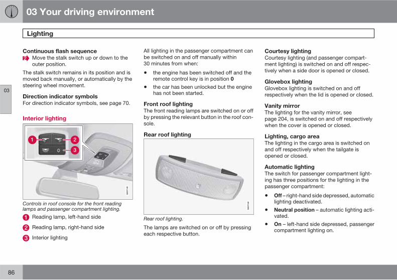
03 Your driving environment
Lighting
03
86
Continuous flash sequence
Move the stalk switch up or down to theouter position.
The stalk switch remains in its position and ismoved back manually, or automatically by thesteering wheel movement.
Direction indicator symbols
For direction indicator symbols, see page 70.
Interior lighting
G02
1149
Controls in roof console for the front readinglamps and passenger compartment lighting.
Reading lamp, left-hand side
Reading lamp, right-hand side
Interior lighting
All lighting in the passenger compartment canbe switched on and off manually within30 minutes from when:
• the engine has been switched off and theremote control key is in position 0
• the car has been unlocked but the enginehas not been started.
Front roof lighting
The front reading lamps are switched on or offby pressing the relevant button in the roof con-sole.
Rear roof lighting
G02
1150
Rear roof lighting.
The lamps are switched on or off by pressingeach respective button.
Courtesy lighting
Courtesy lighting (and passenger compart-ment lighting) is switched on and off respec-tively when a side door is opened or closed.
Glovebox lighting
Glovebox lighting is switched on and offrespectively when the lid is opened or closed.
Vanity mirror
The lighting for the vanity mirror, seepage 204, is switched on and off respectivelywhen the cover is opened or closed.
Lighting, cargo area
The lighting in the cargo area is switched onand off respectively when the tailgate isopened or closed.
Automatic lighting
The switch for passenger compartment light-ing has three positions for the lighting in thepassenger compartment:
• Off – right-hand side depressed, automaticlighting deactivated.
• Neutral position – automatic lighting acti-vated.
• On – left-hand side depressed, passengercompartment lighting on.

03 Your driving environment
Lighting
03
��
87
Neutral position
When the button is in neutral position the pas-senger compartment lighting is switched onand off automatically in accordance with thefollowing.
The passenger compartment lighting isswitched on and remains on for 30 seconds if:
• the car is unlocked with the remote controlkey or key blade, see pages 45 or 48
• the engine is switched off and the remotecontrol key is in position 0.
Passenger compartment lighting is switchedoff when:
• the engine is started
• the car is locked.
The passenger compartment lighting comeson and remains on for two minutes if one of thedoors is open.
If any lighting is switched on manually and thecar is locked then it will be switched off auto-matically after two minutes.
Home safe light duration
Some of the exterior lighting can be keptswitched on to work as home safe lighting afterthe car has been locked.
1. Remove the remote control key from theignition switch.
2. Move the left-hand stalk switch toward thesteering wheel to the end position andrelease it. The function can be activated inthe same way as with main beam flash, seepage 82.
3. Get out of the car and lock the door.
When the function is activated, dipped beam,parking lamps, door mirror lamps, numberplate lighting, interior roof lamps and courtesylighting are switched on.
The length of time for which the home safelighting should be kept on can be set under Car
settings Light settings Home safe light
duration. For a description of the menu sys-tem, see page 130.
Approach light duration
Approach lighting is switched on with theremote control key, see page 45, and is usedto switch on the car's lighting at a distance.
When the function is activated with the remotecontrol, parking lamps, door mirror lamps,number plate lighting, interior roof lamps andcourtesy lighting are switched on.
The length of time for which the approach light-ing should be kept on can be set under Car
settings Light settings Approach light
duration. For a description of the menu sys-tem, see page 130.
Adjusting headlamp pattern
G02
1151
Headlamp pattern, left-hand traffic.
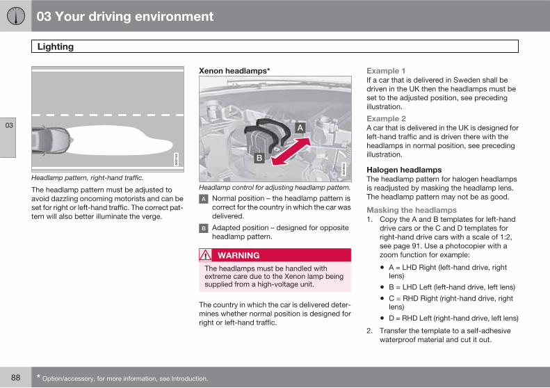
03 Your driving environment
Lighting
03
88 * Option/accessory, for more information, see Introduction.
G02
1152
Headlamp pattern, right-hand traffic.
The headlamp pattern must be adjusted toavoid dazzling oncoming motorists and can beset for right or left-hand traffic. The correct pat-tern will also better illuminate the verge.
Xenon headlamps*
G01
9442
Headlamp control for adjusting headlamp pattern.
Normal position – the headlamp pattern iscorrect for the country in which the car wasdelivered.
Adapted position – designed for oppositeheadlamp pattern.
WARNING
The headlamps must be handled withextreme care due to the Xenon lamp beingsupplied from a high-voltage unit.
The country in which the car is delivered deter-mines whether normal position is designed forright or left-hand traffic.
Example 1
If a car that is delivered in Sweden shall bedriven in the UK then the headlamps must beset to the adjusted position, see precedingillustration.
Example 2
A car that is delivered in the UK is designed forleft-hand traffic and is driven there with theheadlamps in normal position, see precedingillustration.
Halogen headlamps
The headlamp pattern for halogen headlampsis readjusted by masking the headlamp lens.The headlamp pattern may not be as good.
Masking the headlamps
1. Copy the A and B templates for left-handdrive cars or the C and D templates forright-hand drive cars with a scale of 1:2,see page 91. Use a photocopier with azoom function for example:
• A = LHD Right (left-hand drive, rightlens)
• B = LHD Left (left-hand drive, left lens)
• C = RHD Right (right-hand drive, rightlens)
• D = RHD Left (right-hand drive, left lens)
2. Transfer the template to a self-adhesivewaterproof material and cut it out.

03 Your driving environment
Lighting
03
��
89
3. Start from the design line on the headlamplenses, see the dotted line on the side90. Position the self-adhesive templatesat the right distance from each design lineusing the illustration and the dimensions inthe following list:
• A = LHD Right - approx. 86 mm
• B = LHD Left - approx. 40 mm
• C = RHD Right - 0 mm
• D = RHD Left - approx. 96 mm

03 Your driving environment
Lighting
03
90
Aligning the templates
G03
3954
Upper row: masking left-hand drive cars, templates A and B. Lower row: masking right-hand drive cars, templates C and D.

03 Your driving environment
Lighting
03
91
Templates for halogen headlamps
G02
1155
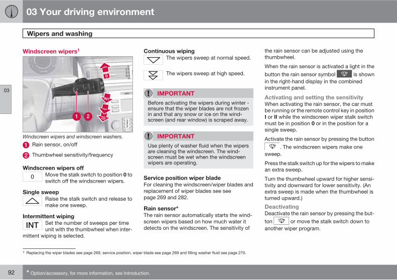
03 Your driving environment
Wipers and washing
03
92 * Option/accessory, for more information, see Introduction.
Windscreen wipers1
Windscreen wipers and windscreen washers.
Rain sensor, on/off
Thumbwheel sensitivity/frequency
Windscreen wipers off
Move the stalk switch to position 0 toswitch off the windscreen wipers.
Single sweep
Raise the stalk switch and release tomake one sweep.
Intermittent wiping
Set the number of sweeps per timeunit with the thumbwheel when inter-
mittent wiping is selected.
Continuous wiping
The wipers sweep at normal speed.
The wipers sweep at high speed.
IMPORTANT
Before activating the wipers during winter -ensure that the wiper blades are not frozenin and that any snow or ice on the wind-screen (and rear window) is scraped away.
IMPORTANT
Use plenty of washer fluid when the wipersare cleaning the windscreen. The wind-screen must be wet when the windscreenwipers are operating.
Service position wiper blade
For cleaning the windscreen/wiper blades andreplacement of wiper blades see seepage 269 and 282.
Rain sensor*
The rain sensor automatically starts the wind-screen wipers based on how much water itdetects on the windscreen. The sensitivity of
the rain sensor can be adjusted using thethumbwheel.
When the rain sensor is activated a light in thebutton the rain sensor symbol is shownin the right-hand display in the combinedinstrument panel.
Activating and setting the sensitivity
When activating the rain sensor, the car mustbe running or the remote control key in positionI or II while the windscreen wiper stalk switchmust be in position 0 or in the position for asingle sweep.
Activate the rain sensor by pressing the button. The windscreen wipers make one
sweep.
Press the stalk switch up for the wipers to makean extra sweep.
Turn the thumbwheel upward for higher sensi-tivity and downward for lower sensitivity. (Anextra sweep is made when the thumbwheel isturned upward.)
Deactivating
Deactivate the rain sensor by pressing the but-ton or move the stalk switch down toanother wiper program.
1 Replacing the wiper blades see page 269, service position, wiper blade see page 269 and filling washer fluid see page 270.

03 Your driving environment
Wipers and washing
03
��
* Option/accessory, for more information, see Introduction. 93
The rain sensor is automatically deactivatedwhen the remote control key is removed fromthe ignition switch or five minutes after theengine has been switched off.
IMPORTANT
The windscreen wipers could start and bedamaged in an automatic car wash. Deac-tivate the rain sensor while the car is runningor the remote control key is in position I orII. The symbol in the combined instrumentpanel and the lamp in the button go out.
Washing the headlamps and windows
Washing function.
Washing the windscreen
Move the stalk switch toward the steeringwheel to start the windscreen and headlampwashers.
The windscreen wipers will make several moresweeps and the headlamps are washed oncethe stalk switch has been released.
Heated washer nozzles*
The washer nozzles are heated automaticallyin cold weather to prevent the washer fluidfreezing solid.
High-pressure headlamp washing*
High-pressure headlamp washing consumes alarge quantity of washer fluid. To save fluid, theheadlamps are washed automatically at everyfifth windscreen wash cycle.
Wiper and washer, rear window
G01
7632
Rear window wiper – intermittent wiping
Rear window wiper – continuous speed
Press the stalk switch forward (see the arrowin the illustration above) to initiate rear windowwashing and wiping.
NOTE
The rear window wiper is equipped withoverheating protection which means thatthe motor is switched off if it overheats. Therear window wiper works again after a cool-ing period (30 seconds or longer, dependingon the heat in the motor and the outsidetemperature).

03 Your driving environment
Wipers and washing
03
94
Wiper – reversing
Engaging reverse gear while the windscreenwipers are on initiates intermittent rear windowwiping2. The function stops when reverse gearis disengaged.
If the rear window wiper is already on at con-tinuous speed, no change is made.
NOTE
On cars with rain sensor, the rear windowwiper is activated with reversing, if the sen-sor is activated and it is raining.
2 This function (intermittent wiping when reversing) can be deactivated. Visit a workshop. Volvo recommends that you contact an authorised Volvo workshop.
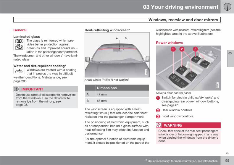
03 Your driving environment
Windows, rearview and door mirrors
03
��
* Option/accessory, for more information, see Introduction. 95
General
Laminated glass
The glass is reinforced which pro-vides better protection againstbreak-ins and improved sound insu-lation in the passenger compartment.
The windscreen and other windows* have lami-nated glass.
Water and dirt-repellent coating*
Windows are treated with a coatingthat improves the view in difficult
weather conditions. Maintenance, seepage 283.
IMPORTANT
Do not use a metal ice scraper to remove icefrom the windows. Use the defroster toremove ice from the mirrors, seepage 98.
Heat-reflecting windscreen*
Areas where IR film is not applied.
Dimensions
A 47 mm
B 87 mm
The windscreen is equipped with a heat-reflecting film (IR) that reduces the solar heatradiation into the passenger compartment.
The positioning of electronic equipment, suchas a transponder, behind a glass surface withheat-reflecting film may affect its function andperformance.
For the optimal function of electronic equip-ment, it should be positioned on the part of the
windscreen with no heat-reflecting film (see thehighlighted area in the above illustration).
Power windows
G01
8516
Driver's door control panel.
Switch for electric child safety locks* anddisengaging rear power window buttons,see page 61.
Rear window controls
Front window controls
WARNING
Check that none of the rear seat passengersis in danger of becoming trapped in any waywhen closing the windows from the driver'sdoor.

03 Your driving environment
Windows, rearview and door mirrors
03
96
WARNING
Make sure that children or other passengersare not in danger of becoming trapped inany way when closing the windows, in par-ticular when the remote control key is used.
WARNING
If there are children in the car, remember toalways switch off the power supply to thepower windows by removing the remotecontrol key if the driver leaves the car.
Operating
G01
8517
Operating the power windows.
Operating without auto
Operating with auto
All power windows can be operated using thecontrol panel in the driver's door. Each controlpanel in the other doors can only control itsown respective power window. The power win-dows can only be controlled with one controlpanel at a time.
In order that the power windows can be usedthe remote control key must be in position I orII. After the car has been running the powerwindows can be operated for several minuteseven when the remote control key has beenremoved, but not however after the door hasbeen opened.
Closing of the windows is stopped and thewindow is opened if anything prevents itsmovement. It is possible to force the pinch pro-tection when closing has been interrupted, e.g.with ice, by continuously holding the button upuntil the window is closed. The pinch protec-tion is reactivated after a brief pause.
NOTE
One way to reduce the pulsating wind noisewhen the rear windows are open is to alsoopen the front windows slightly.
Operating without auto
Move one of the controls up/down gently. Thepower windows move up/down as long as thecontrol is held in position.
Operating with auto
Move one of the controls up/down to the endposition and release it. The window runs auto-matically to its end position.
Operating with the remote control key
and central locking
To remotely operate the power windows fromthe outside with the remote control key or frominside with central locking, see pages 45 and56
Resetting
If the battery is disconnected then the functionfor automatic opening must be reset so that itcan work correctly.
1. Gently raise the front section of the buttonto raise the window to its end position andhold it there for one second.
2. Release the button briefly.
3. Raise the front section of the button againfor one second.
WARNING
Resetting must be carried out to ensure thatpinch protection works.

03 Your driving environment
Windows, rearview and door mirrors
03
��
* Option/accessory, for more information, see Introduction. 97
Door mirrors
G01
8518
Door mirror controls.
Adjusting
1. Press the L button for the left-hand doormirror or the R button for the right-handdoor mirror. The light in the button illumi-nates.
2. Adjust the position with the joystick in thecentre.
3. Press the L or R button again. The lightshould no longer be illuminated.
WARNING
The mirrors are the wide angle type for opti-mum surveillance. Objects may appear fur-ther away than they actually are.
Retractable power door mirrors*
The mirrors can be retracted for parking/drivingin narrow spaces:
1. Press the buttons L and R simultaneously(the remote control key must be at least inkey position I).
2. Release them afterapproximately 1 second. The mirrors auto-matically stop in the fully retracted posi-tion.
Fold out the mirrors by pressing down the Land R buttons simultaneously. The mirrorsautomatically stop in the fully extended posi-tion.
Storing the position*
The mirror positions are stored in the key mem-ory when the car has been locked with theremote control key. When the car is unlockedwith the same remote control key the mirrorsand the driver's seat adopt the stored positionswhen the driver's door is opened.
The function can be activated/deactivatedunder Car Key memory Seat & mirror
positions. For a description of the menu sys-tem, see page 130.
Angling the door mirror when parking1
The door mirror can be angled down for thedriver to view the side of the road when parkingfor example.
� Engage reverse gear and press the L or Rbutton.
When reverse gear is disengaged the mirrorautomatically returns to its original positionafter about 10 seconds, or earlier by pressingthe button labelled L or R respectively
Automatic angling of the door mirror
when parking1
When reverse gear is engaged the door mirroris automatically angled down so that the drivercan see the side of the road when parking forexample. When reverse gear is disengaged themirror automatically returns to its original posi-tion after a while.
The function can be activated/deactivatedunder Car settings Side mirror settings
Auto tilt left mirror or Auto tilt right
mirror. For a description of the menu system,see page 130.
Automatic retraction when locking
When the car is locked/unlocked with theremote control key the door mirrors are auto-matically retracted/extended.
1 Only in combination with power seat with memory, see page 77.

03 Your driving environment
Windows, rearview and door mirrors
03
98 * Option/accessory, for more information, see Introduction.
The function can be activated/deactivatedunder Car settings Side mirror settings
Fold mirr. when locking. For a descriptionof the menu system, see page 130.
Resetting to neutral
Mirrors that have been moved out of positionby an external force must be reset electricallyto the neutral position for electric retracting/extending to work correctly:
1. Retract the mirrors with the L and R but-tons.
2. Fold them out again with the L and R but-tons.
3. Repeat the above procedure as necessary.
The mirrors are now reset in neutral position.
Home safe and approach lighting
The light on the door mirrors illuminates whenapproach lighting or home safe lighting isselected, see page 87.
Rear window and door mirrordefrosters
Use the defroster to quickly remove mistingand ice from the rear window and the door mir-rors.
One press of the button starts the heating. Thelight in the button indicates that the function isactive. Disconnect the heating as soon as theice/misting is cleared in order not to load thebattery unnecessarily. However, the heating isswitched off automatically after a certain time.
The heating can be engaged automatically ifthe car is started in an outside temperaturelower than +7 °C. The automatic defrostingfunction must then be activated under Climate
settings Auto. rear defroster. For adescription of the menu system, seepage 130.
Interior rearview mirror
G02
1342
Control for dimming
Manual dimming
Bright light from behind could be reflected inthe rearview mirror and dazzle the driver. Usedimming with the dimming control when lightsfrom behind are distracting:
1. Use dimming by moving the control intowards the passenger compartment.
2. Return to normal position by moving thecontrol towards the windscreen.
Automatic dimming*
Bright light from behind is automaticallydimmed by the rearview mirror. The control isnot available in mirrors with automatic dim-ming.

03 Your driving environment
Windows, rearview and door mirrors
03
* Option/accessory, for more information, see Introduction. 99
The compass* can only be specified for rear-view mirrors with automatic dimming, seepage 100.
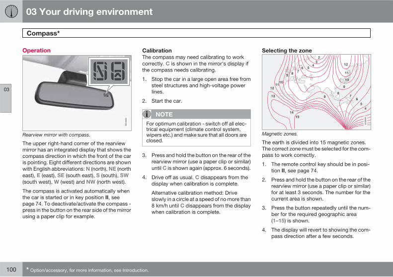
03 Your driving environment
Compass*
03
100 * Option/accessory, for more information, see Introduction.
Operation
Rearview mirror with compass.
The upper right-hand corner of the rearviewmirror has an integrated display that shows thecompass direction in which the front of the caris pointing. Eight different directions are shownwith English abbreviations: N (north), NE (northeast), E (east), SE (south east), S (south), SW
(south west), W (west) and NW (north west).
The compass is activated automatically whenthe car is started or in key position II, seepage 74. To deactivate/activate the compass -press in the button on the rear side of the mirrorusing a paper clip for example.
Calibration
The compass may need calibrating to workcorrectly. C is shown in the mirror's display ifthe compass needs calibrating.
1. Stop the car in a large open area free fromsteel structures and high-voltage powerlines.
2. Start the car.
NOTE
For optimum calibration - switch off all elec-trical equipment (climate control system,wipers etc.) and make sure that all doors areclosed.
3. Press and hold the button on the rear of therearview mirror (use a paper clip or similar)until C is shown again (approx. 6 seconds).
4. Drive off as usual. C disappears from thedisplay when calibration is complete.
Alternative calibration method: Driveslowly in a circle at a speed of no more than8 km/h until C disappears from the displaywhen calibration is complete.
Selecting the zone
G03
0295
Magnetic zones.
The earth is divided into 15 magnetic zones.The correct zone must be selected for the com-pass to work correctly.
1. The remote control key should be in posi-tion II, see page 74.
2. Press and hold the button on the rear of therearview mirror (use a paper clip or similar)for at least 3 seconds. The number for thecurrent area is shown.
3. Press the button repeatedly until the num-ber for the required geographic area(1–15) is shown.
4. The display will revert to showing the com-pass direction after a few seconds.
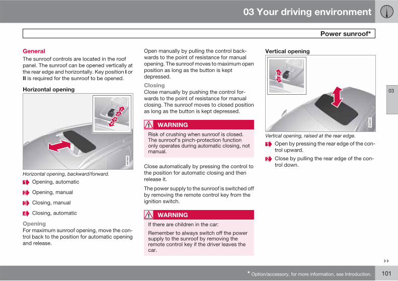
03 Your driving environment
Power sunroof*
03
��
* Option/accessory, for more information, see Introduction. 101
General
The sunroof controls are located in the roofpanel. The sunroof can be opened vertically atthe rear edge and horizontally. Key position I orII is required for the sunroof to be opened.
Horizontal opening
G01
7823
Horizontal opening, backward/forward.
Opening, automatic
Opening, manual
Closing, manual
Closing, automatic
Opening
For maximum sunroof opening, move the con-trol back to the position for automatic openingand release.
Open manually by pulling the control back-wards to the point of resistance for manualopening. The sunroof moves to maximum openposition as long as the button is keptdepressed.
Closing
Close manually by pushing the control for-wards to the point of resistance for manualclosing. The sunroof moves to closed positionas long as the button is kept depressed.
WARNING
Risk of crushing when sunroof is closed.The sunroof's pinch-protection functiononly operates during automatic closing, notmanual.
Close automatically by pressing the control tothe position for automatic closing and thenrelease it.
The power supply to the sunroof is switched offby removing the remote control key from theignition switch.
WARNING
If there are children in the car:
Remember to always switch off the powersupply to the sunroof by removing theremote control key if the driver leaves thecar.
Vertical opening
G02
8900
Vertical opening, raised at the rear edge.
Open by pressing the rear edge of the con-trol upward.
Close by pulling the rear edge of the con-trol down.
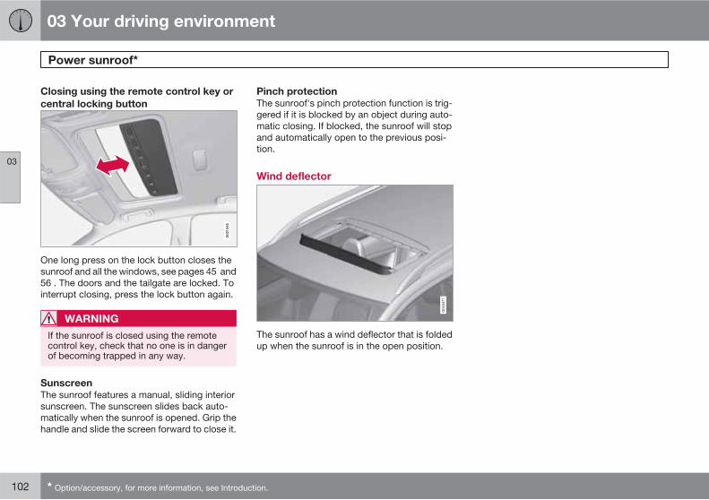
03 Your driving environment
Power sunroof*
03
102 * Option/accessory, for more information, see Introduction.
Closing using the remote control key or
central locking button
G02
1345
One long press on the lock button closes thesunroof and all the windows, see pages 45 and56 . The doors and the tailgate are locked. Tointerrupt closing, press the lock button again.
WARNING
If the sunroof is closed using the remotecontrol key, check that no one is in dangerof becoming trapped in any way.
Sunscreen
The sunroof features a manual, sliding interiorsunscreen. The sunscreen slides back auto-matically when the sunroof is opened. Grip thehandle and slide the screen forward to close it.
Pinch protection
The sunroof's pinch protection function is trig-gered if it is blocked by an object during auto-matic closing. If blocked, the sunroof will stopand automatically open to the previous posi-tion.
Wind deflector
The sunroof has a wind deflector that is foldedup when the sunroof is in the open position.
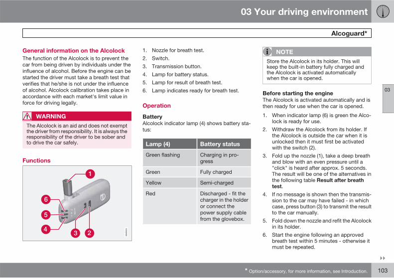
03 Your driving environment
Alcoguard*
03
��
* Option/accessory, for more information, see Introduction. 103
General information on the Alcolock
The function of the Alcolock is to prevent thecar from being driven by individuals under theinfluence of alcohol. Before the engine can bestarted the driver must take a breath test thatverifies that he/she is not under the influenceof alcohol. Alcolock calibration takes place inaccordance with each market's limit value inforce for driving legally.
WARNING
The Alcolock is an aid and does not exemptthe driver from responsibility. It is always theresponsibility of the driver to be sober andto drive the car safely.
Functions
1. Nozzle for breath test.2. Switch.3. Transmission button.4. Lamp for battery status.5. Lamp for result of breath test.6. Lamp indicates ready for breath test.
Operation
Battery
Alcolock indicator lamp (4) shows battery sta-tus:
Lamp (4) Battery status
Green flashing Charging in pro-gress
Green Fully charged
Yellow Semi-charged
Red Discharged - fit thecharger in the holderor connect thepower supply cablefrom the glovebox.
NOTE
Store the Alcolock in its holder. This willkeep the built-in battery fully charged andthe Alcolock is activated automaticallywhen the car is opened.
Before starting the engine
The Alcolock is activated automatically and isthen ready for use when the car is opened.
1. When indicator lamp (6) is green the Alco-lock is ready for use.
2. Withdraw the Alcolock from its holder. Ifthe Alcolock is outside the car when it isunlocked then it must first be activatedwith the switch (2).
3. Fold up the nozzle (1), take a deep breathand blow with an even pressure until a"click" is heard after approx. 5 seconds.The result will be one of the alternatives inthe following table Result after breath
test.4. If no message is shown then the transmis-
sion to the car may have failed - in whichcase, press button (3) to transmit the resultto the car manually.
5. Fold down the nozzle and refit the Alcolockin its holder.
6. Start the engine following an approvedbreath test within 5 minutes - otherwise itmust be repeated.
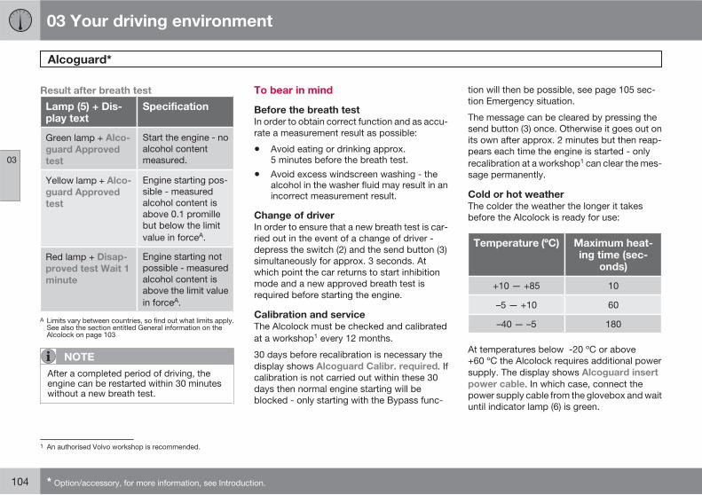
03 Your driving environment
Alcoguard*
03
104 * Option/accessory, for more information, see Introduction.
Result after breath test
Lamp (5) + Dis-play text
Specification
Green lamp + Alco-
guard Approved
test
Start the engine - noalcohol contentmeasured.
Yellow lamp + Alco-
guard Approved
test
Engine starting pos-sible - measuredalcohol content isabove 0.1 promillebut below the limitvalue in forceA.
Red lamp + Disap-
proved test Wait 1
minute
Engine starting notpossible - measuredalcohol content isabove the limit valuein forceA.
A Limits vary between countries, so find out what limits apply.See also the section entitled General information on theAlcolock on page 103
NOTE
After a completed period of driving, theengine can be restarted within 30 minuteswithout a new breath test.
To bear in mind
Before the breath test
In order to obtain correct function and as accu-rate a measurement result as possible:
• Avoid eating or drinking approx.5 minutes before the breath test.
• Avoid excess windscreen washing - thealcohol in the washer fluid may result in anincorrect measurement result.
Change of driver
In order to ensure that a new breath test is car-ried out in the event of a change of driver -depress the switch (2) and the send button (3)simultaneously for approx. 3 seconds. Atwhich point the car returns to start inhibitionmode and a new approved breath test isrequired before starting the engine.
Calibration and service
The Alcolock must be checked and calibratedat a workshop1 every 12 months.
30 days before recalibration is necessary thedisplay shows Alcoguard Calibr. required. Ifcalibration is not carried out within these 30days then normal engine starting will beblocked - only starting with the Bypass func-
tion will then be possible, see page 105 sec-tion Emergency situation.
The message can be cleared by pressing thesend button (3) once. Otherwise it goes out onits own after approx. 2 minutes but then reap-pears each time the engine is started - onlyrecalibration at a workshop1 can clear the mes-sage permanently.
Cold or hot weather
The colder the weather the longer it takesbefore the Alcolock is ready for use:
Temperature (ºC) Maximum heat-ing time (sec-
onds)
+10 — +85 10
–5 — +10 60
–40 — –5 180
At temperatures below -20 ºC or above+60 ºC the Alcolock requires additional powersupply. The display shows Alcoguard insert
power cable. In which case, connect thepower supply cable from the glovebox and waituntil indicator lamp (6) is green.
1 An authorised Volvo workshop is recommended.

03 Your driving environment
Alcoguard*
03
��
* Option/accessory, for more information, see Introduction. 105
In extremely cold weather the heating time canbe reduced by taking the Alcolock indoors.
Emergency situation
In the event of an emergency situation, or if theAlcolock is out of order or has been removed,it is possible to bypass the Alcolock in order todrive the car.
NOTE
All Bypass activation is logged and saved inmemory, see page 10 in the section,Recording data.
After the Bypass function has been activatedthe display shows Alcoguard Bypass
enabled the whole time while driving and canonly be reset by a workshop1.
The Bypass function can be tested without theerror message being logged - in which case,carry out all the steps without starting the car.The error message is cleared when the car islocked.
When the Alcolock is installed, either theBypass or Emergency function is selected asthe bypassing option. This setting can bechanged afterwards at a workshop1.
Activating the Bypass function
• Depress and hold the left-hand stalkswitch READ button and the button forhazard warning flashers simultaneously forapprox. 5 seconds - the display first showsBypass activated Wait 1 minute andthen Alcoguard Bypass enabled - afterwhich the engine can be started.
This function can be activated several times.The error message shown during driving canonly be cleared at a workshop1.
Activating the Emergency function
• Depress and hold the left-hand stalkswitch READ button and the button forhazard warning flashers simultaneously forapprox. 5 seconds - the display showsAlcoguard Bypass enabled and theengine can be started.
This function can be used once, after which areset must be made at a workshop1.
Symbols and display messages
In addition to the previously described mes-sages, the combined instrument panel's dis-play can also show the following:
Display text Meaning/Action
Alcoguard Restart
possible
The engine has beenswitched off for lessthan 30 minutes -engine starting pos-sible without newtest.
Alcoguard Service
required
Contact a work-shop1.
Alcoguard No sig-
nal
Transmission failed -send manually withbutton (3) or take anew breath test.
Alcoguard Invalid
test
Test failed - take anew breath test.
Alcoguard Blow
longer
Blowing too short -blow for longer.
Alcoguard Blow
softer
Blowing too hard -blow more gently.
1 An authorised Volvo workshop is recommended.

03 Your driving environment
Alcoguard*
03
106 * Option/accessory, for more information, see Introduction.
Display text Meaning/Action
Alcoguard Blow
harder
Blowing too weak -blow harder.
Alcoguard wait
Preheating
Heating not finished- wait for text Alco-
guard Blow 5 sec-
onds.

03 Your driving environment
Starting the engine
03
��
* Option/accessory, for more information, see Introduction. 107
Petrol and diesel engines
G02
1126
Ignition switch with inserted remote control keyand START/STOP ENGINE button.
IMPORTANT
Do not press in the remote control key incor-rectly turned - Hold the end with the detach-able key blade, see page 47.
1. Fit the remote control key in the ignitionswitch - Gently press the key until it isdrawn into the lock. Note that if the car isequipped with an alcolock then a breathtest must first be approved before theengine can be started, see page 103.
2. Hold the clutch pedal fully depressed1. (Forcars with automatic gearbox - Depress thebrake pedal.)
3. Press the START/STOP ENGINE buttonand then release it.
NOTE
For diesel-engined cars, there may be aslight delay before the engine can be started- Engine Preheating is displayed in themeantime.
The starter motor works until the engine hasstarted, but for no longer than 10 seconds (die-sel up to 60 seconds).
If the engine does not start - try again by hold-ing in the START/STOP ENGINE button untilthe engine starts.
WARNING
Always remove the remote control key fromthe ignition switch when leaving the car -especially if there are children in the car. Forinformation on how the key is removed fromthe ignition switch, see page 74.
NOTE
The idling speed can be noticeably higherthan normal for certain engine types duringcold starting. This is so that the emissionssystem can reach normal operating tem-perature as quickly as possible, which min-imises exhaust emissions and protects theenvironment.
Keyless drive
Follow steps 2–3 for starting petrol and dieselengines. For more information on Keylessdrive, see page 53.
NOTE
One precondition for starting the car is thatone of the car's remote control keys with thekeyless drive* function is located inside thepassenger compartment or the cargo area.
WARNING
Never remove the remote control key withthe Keyless drive* function from the carwhile driving or during towing.
Stop the engine
To switch off the engine - Press START/STOP
ENGINE.
1 If the car is moving then it is enough to press the START/STOP ENGINE button to start the car.

03 Your driving environment
Starting the engine
03
108
If the car has an automatic gearbox and thegear selector is not in a position P or if the caris moving - Press twice or hold the buttondepressed until the engine stops.
Steering lock
The steering lock opens when the START/
STOP ENGINE button is depressed after theremote control key has been pressed into theignition switch.
The steering lock is activated when the driver'sdoor is opened after the engine has beenswitched off.
Key positions
For information on the remote control key's dif-ferent key positions, see page 74
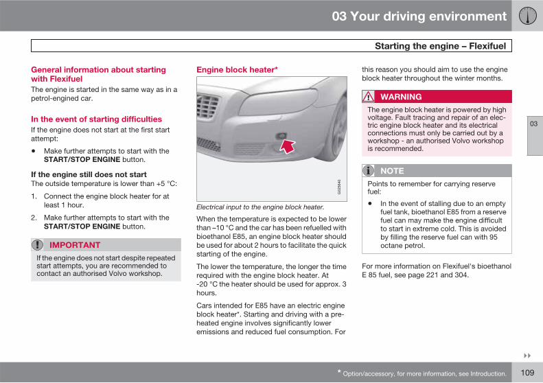
03 Your driving environment
Starting the engine – Flexifuel
03
��
* Option/accessory, for more information, see Introduction. 109
General information about startingwith Flexifuel
The engine is started in the same way as in apetrol-engined car.
In the event of starting difficulties
If the engine does not start at the first startattempt:
• Make further attempts to start with theSTART/STOP ENGINE button.
If the engine still does not start
The outside temperature is lower than +5 °C:
1. Connect the engine block heater for atleast 1 hour.
2. Make further attempts to start with theSTART/STOP ENGINE button.
IMPORTANT
If the engine does not start despite repeatedstart attempts, you are recommended tocontact an authorised Volvo workshop.
Engine block heater*
Electrical input to the engine block heater.
When the temperature is expected to be lowerthan –10 °C and the car has been refuelled withbioethanol E85, an engine block heater shouldbe used for about 2 hours to facilitate the quickstarting of the engine.
The lower the temperature, the longer the timerequired with the engine block heater. At-20 °C the heater should be used for approx. 3hours.
Cars intended for E85 have an electric engineblock heater*. Starting and driving with a pre-heated engine involves significantly loweremissions and reduced fuel consumption. For
this reason you should aim to use the engineblock heater throughout the winter months.
WARNING
The engine block heater is powered by highvoltage. Fault tracing and repair of an elec-tric engine block heater and its electricalconnections must only be carried out by aworkshop - an authorised Volvo workshopis recommended.
NOTE
Points to remember for carrying reservefuel:
• In the event of stalling due to an emptyfuel tank, bioethanol E85 from a reservefuel can may make the engine difficultto start in extreme cold. This is avoidedby filling the reserve fuel can with 95octane petrol.
For more information on Flexifuel's bioethanolE 85 fuel, see page 221 and 304.

03 Your driving environment
Starting the engine – Flexifuel
03
110
Fuel adaptation
If the fuel tank is filled with petrol after the carhas been driven on bioethanol E85 (or viceversa) then the engine may run slightlyunevenly for a time. For this reason it is impor-tant to allow the engine to accustom itself(adapt) to the new fuel mixture.
Adaptation takes place automatically when thecar is driven for a short period at an evenspeed.
IMPORTANT
After the fuel mixture in the tank has beenchanged an adaptation should be made bydriving at an even speed for about 15minutes.
If the battery has been discharged or discon-nected then a slightly longer period of drivingis required for the adaptation as the memoryfor the electronics has been cleared.

03 Your driving environment
Starting the engine – external battery
03
111
Jump starting
If the battery is flat then the car can be startedwith current from another battery.
The following points are recommended whenusing a donor battery in order to avoid the riskof an explosion:
1. Insert the remote control key in key posi-tion 0, see page 74.
2. Ensure that the donor battery is 12 volt.
3. If the donor battery is in another car, switchoff the donor car's engine in the other carand ensure that the cars do not touch oneanother.
4. Connect the red jump lead to the positiveterminal on the donor battery .
5. Open the clips on the front cover of thebattery in your car and remove the cover,see page 272.
6. Connect the red jump lead to the battery'spositive terminal .
7. Connect one end of the black jump lead tothe donor battery's negative terminal .
IMPORTANT
Connect the start cable carefully to avoidshort circuits with other components in theengine compartment.
8. Connect the other clamp to an earthingpoint, (right-hand engine mounting at thetop, the outer screw head) . Check thatthe jump lead clamps are fixed securely sothat there are no sparks during the startingprocedure.
9. Start the engine of the "donor car". Let theengine run a few minutes at a speed slightlyhigher than idle (1500 rpm).
10. Start the engine of the car with the flat bat-tery. Do not touch the crocodile clips dur-ing the start procedure. There is a risk ofsparks forming.
11. Remove the jump leads, first the black andthen the red.
Make sure that none of the clamps on theblack jump lead comes into contact withthe battery's positive terminal or the clampconnected to the red jump lead.
WARNING
The battery can generate oxyhydrogen gas,which is highly explosive. One spark, whichcan be generated if you connect a jump leadincorrectly, is sufficient to make the batteryexplode. The battery contains sulphuricacid, which can cause serious burns. If theacid comes into contact with eyes, skin orclothing, flush with large quantities of water.If acid splashes into the eyes, seek medicalattention immediately.
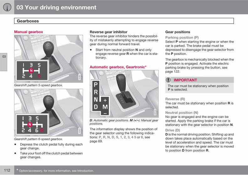
03 Your driving environment
Gearboxes
03
112 * Option/accessory, for more information, see Introduction.
Manual gearbox
Gearshift pattern 5-speed gearbox.
Gearshift pattern 6-speed gearbox.
• Depress the clutch pedal fully during eachgear change.
• Take your foot off the clutch pedal betweengear changes.
Reverse gear inhibitor
The reverse gear inhibitor hinders the possibil-ity of mistakenly attempting to engage reversegear during normal forward travel.
• Start from neutral position N and onlyengage reverse gear R when the car is sta-tionary.
Automatic gearbox, Geartronic*
G02
1350
D: Automatic gear positions. M (+/–): Manual gearpositions.
The information display shows the position ofthe gear selector using the following indica-tions: P, R, N, D, S, 1, 2, 3, 4 5 or 6, seepage 69.
Gear positions
Parking position (P)
Select P when starting the engine or when thecar is parked. The brake pedal must bedepressed to disengage the gear selector fromthe P position.
The gearbox is mechanically blocked when theP position is engaged. Activate the electricparking brake by pressing the button, seepage 122.
IMPORTANT
The car must be stationary when positionP is selected.
Reverse (R)
The car must be stationary when position R isselected.
Neutral position (N)
No gear is engaged and the engine can bestarted. Apply the parking brake if the car isstationary with the gear selector in position N.
Drive (D)
D is the normal driving position. Shifting up anddown takes place automatically based on thelevel of acceleration and speed. The car mustbe stationary when the gear selector is movedto position D from position R.

03 Your driving environment
Gearboxes
03
��
113
Geartronic – Manual gear positions (+/-)
The driver can also change gear manuallyusing the Geartronic automatic gearbox. Thecar engine-brakes when the accelerator pedalis released.
Manual gearshift mode is obtained by movingthe lever to the side from position D to the endposition at +/–. The information display shiftsthe indication from D to one of the figures 1 –6, which is equivalent to the gear that isengaged just then, see page 69.
• Move the lever forwards towards + (plus)to change up a gear and release the lever,which returns to its rest position between+ and –.
or
• Pull the lever back towards – (minus) tochange down a gear and release it.
The manual gearshift mode (+/–) can beselected at any time while driving.
Geartronic automatically shifts down if thedriver allows the speed to decrease lower thana level suitable for the selected gear, in orderto avoid jerking and stalling.
To return to automatic driving mode:
• Move the lever to the side to the end posi-tion at D.
NOTE
f the gearbox has a Sport programme thenthe gearbox will only become manual afterthe lever has been moved forwards or back-wards in its (-+/–) position. The informationdisplay then shifts the indication from S toshow which of the gears 1-6 is engaged.
Geartronic - Sport mode (S)1
The Sport programme provides sportier cha-racteristics and allows higher engine speed forthe gears. At the same time it responds morequickly to acceleration. During active driving,the use of a lower gear is prioritised, leading toa delayed upshift.
Sport mode is obtained by moving the lever tothe side from D position to the end position at+/–. The information display shifts the indica-tion from D to S.
Sport mode can be selected at any time whiledriving.
Geartronic - Winter mode
It can be easier to pull away on slippery roadsif 3rd gear is engaged manually.
1. Depress the brake pedal and move thegear lever from the D position to the endposition at +/– - the instrument panel dis-
play shifts the indication from D to the fig-ure 1.
2. Scroll up to gear 3 by pushing the leverforward towards + (plus) twice - the displayshifts the indication from 1 to 3.
3. Release the brake and accelerate carefully.
The gearbox "winter mode" means that the carmoves off with a lower engine speed andreduced engine power on the drive wheels.
Kick-down
When the accelerator pedal is pressed all theway to the floor (beyond the position normallyregarded as full acceleration) a lower gear isimmediately engaged. This is known as kick-down.
If the accelerator is released from the kick-down position, the gearbox automaticallychanges up.
Kick-down is used when maximum accelera-tion is needed, such as for overtaking.
Safety function
To prevent overrevving the engine, the gearboxcontrol program has a protective downshiftinhibitor which prevents the kick-down func-tion.
1 Only models D5 and T6.

03 Your driving environment
Gearboxes
03
114
Geartronic does not permit downshifting/kick-down which would result in an engine speedhigh enough to damage the engine. Nothinghappens if the driver still tries to shift down inthis way at high engine speed – the originalgear remains engaged.
When kick-down is activated the car canchange one or more gears at a time dependingon engine speed. The car changes up when theengine reaches its maximum speed in order toprevent damage to the engine.
Mechanical gear selector inhibitorG
0213
51
The gear selector can be moved forward andback freely between N and D. Other positionsare locked with a latch that is released with theinhibitor button on the gear selector.
With the inhibitor button depressed the levercan be moved forwards or backwards betweenP, R, N and D.
Automatic gear selector inhibitor
The automatic gearbox has special safety sys-tems:
Keylock
To remove the remote control key from theignition switch, the gear selector must be in theP position. The remote control key is locked inall other positions.
Parking position (P)
Stationary car with engine running:
Keep your foot on the brake pedal when mov-ing the gear selector to another position.
Electric gear inhibitor – Shiftlock Parking
position (P)
To be able to move the gear selector from P toother gear positions, the brake pedal must bedepressed and the remote control key must bein position II, see page 74.
Shiftlock – Neutral (N)
If the gear selector is in the N position and thecar has been stationary for at least 3 seconds(irrespective of whether the engine is running)then the gear selector is locked.
To be able to move the gear selector from N toother gear positions, the brake pedal must be
depressed and the remote control key must bein position II, see page 74.
Deactivating the automatic gear selector
inhibitor
If the car cannot be driven, e.g. due to a flatbattery, the gear selector must be moved fromthe P position so that the car can be moved.
Lift the rubber mat in the compartmentbehind the centre console and open thehatch.
Fully insert the key blade. Press the keyblade down and hold (For information onthe key blade, see page 47.)
Move the gear selector from the P position.

03 Your driving environment
Gearboxes
03
��
* Option/accessory, for more information, see Introduction. 115
Automatic gearbox, Powershift*2
G02
1350
D: Automatic gear positions. M (+/–): Manual gearpositions.
Powershift is a six-stage automatic gearboxthat has double mechanical clutch discs incontrast to a conventional automatic gearbox.A conventional automatic gearbox has ahydraulic torque converter that transfers powerfrom the engine to the gearbox.
Powershift transmission operates in the sameway and has similar controls and functions as
the Geartronic automatic transmission, descri-bed in the previous section.
HSA
The HSA (Hill Start Assist) function means thatthe pressure in the brake system remains forseveral seconds while the foot is moved fromthe brake pedal to the accelerator pedal beforesetting off or reversing uphill.
The temporary braking effect releases afterseveral seconds or when the driver acceler-ates.
To bear in mind
The transmission's double clutch has overloadprotection that is activated if it becomes toohot, e.g. if the car is held stationary with theaccelerator pedal on an uphill gradient for along time.
Overheated transmission causes the car toshake and vibrate, and the warning symbol illu-minates and the information display shows amessage. The transmission can also overheat
during slow driving in queues (10 km/h orslower) on an uphill gradient, or with a trailerhitched. The transmission cools down whenthe car is stationary, with foot brake depressedand the engine running at idling speed.
Overheating during slow driving in queues canbe avoided by driving in stages: Stop the carand wait with your foot on the brake pedal untilthere is a moderate distance to the trafficahead, drive forward a short distance, and thenwait another moment with your foot on thebrake pedal.
IMPORTANT
Use the foot brake to hold the car stationaryon an uphill gradient - do not hold the carwith the accelerator pedal. The gearboxcould then overheat.
Text message and action
In some situations the display may show amessage at the same time as a symbol is illu-minated.
2 Only 4-cyl. model 2.0, 2.0T, 2.0F.

03 Your driving environment
Gearboxes
03
116
Symbol Display Driving characteristics Action
Transm. overheat brake to hold Difficulty in maintaining even speed at con-stant engine speed.
Transmission overheated. Keep the carstationary using the foot brake.A
Transm. overheat park safely Significant pulling in the car's traction. Transmission overheated. Park the carimmediately in a safe manner.A
Transm. cooling let engine run No drive due to overheated gearbox. Transmission overheated. For fastest cool-ing: Run the engine at idling speed with thegear lever in the N or P position until themessage clears.
A For fastest cooling: run the engine at idling speed with the gear lever in the N or P position, until the message clears.
The table shows three steps with an increaseddegree of seriousness should the transmissionbecome too hot. In parallel with the display textthe driver is also advised that the car's elec-tronics are temporarily changing the drivingcharacteristics. Follow the instructions on theinformation display where appropriate.
NOTE
The table's examples are no indication thatthe car is defective but instead show that asafety function has been activated inten-tionally to prevent damage to one of thecar's components.
WARNING
If a warning symbol combined with the textTransm. overheat park safely is ignoredthen the heat in the gearbox may becomeso high that the power transmissionbetween engine and gearbox is temporarilyhalted in order to prevent the clutch frommalfunctioning - the car then loses drive andis stationary until gearbox temperature hascooled to an acceptable level.
For more possible display messages with theirrespective proposals for solutions concerningautomatic transmission, see page 134.
A display text clears automatically after theaction has been carried out or after one presson the indicator stalk READ button.

03 Your driving environment
All-wheel drive – AWD*
03
* Option/accessory, for more information, see Introduction. 117
All Wheel Drive is always available
All Wheel Drive means that the car is driving allfour wheels at the same time.
The power is automatically distributedbetween the front and rear wheels. An elec-tronically controlled clutch system distributesthe power to the wheels that have the best gripon the current road surface. This provides thebest traction and prevents wheel spin. Undernormal driving conditions, the majority ofpower is transmitted to the front wheels.
All Wheel Drive improves driving safety in rain,snow and icy conditions.
03 Your driving environment
Foot brake
03
118
General
The car is equipped with two brake circuits. Ifone brake circuit is damaged then this willmean that the brakes engage at a deeper leveland harder pressure on the pedal is needed toproduce the normal braking effect.
The driver's brake pedal pressure is assistedby a brake servo.
WARNING
The brake servo only works when the engineis running.
If the brake is used when the engine is switchedoff then the pedal will feel stiff and more forcemust be used to brake the car.
In very hilly terrain or when driving with a heavyload the brakes can be relieved by using enginebraking. Engine braking is most efficiently usedif the same gear is used downhill as up.
For more general information on heavy loadson the car, see page 300.
Anti-lock braking system
The car is equipped with ABS (Anti-lockBraking System) which prevents the wheelsfrom locking during braking. This means theability to steer is maintained and it is easier toswerve to avoid a hazard for example. Vibration
may be felt in the brake pedal when this isengaged and this is normal.
A short test of the ABS system is made auto-matically after the engine has been startedwhen the driver releases the brake pedal. Afurther automatic test of the ABS system maybe made when the car reaches 40 km/h. Thetest may be experienced as pulses in the brakepedal.
Emergency brake lights and automatic
hazard warning flashers
Emergency brake lights are activated to alertvehicles behind about sudden braking. Thefunction means that the brake light flashesinstead of - as in normal braking - shining witha constant glow.
Emergency brake lights are activated atspeeds above 50 km/h if the ABS system isworking and/or in the event of sudden braking.After the car's speed has been slowed below10 km/h the brake light returns from flashing tothe normal constant glow - while at the sametime the hazard warning flashers are activated,and they flash until the driver changes enginespeed with the accelerator pedal or they aredeactivated with their button, see page 85.
Cleaning the brake discs
Coatings of dirt and water on the brake discsmay result in delayed brake function. This delayis minimised by cleaning the brake linings.
Manual cleaning is advisable with wet road sur-faces, prior to long-stay parking and after thecar has been washed. Carry this out by brakinggently during a short period while en route.
Emergency Brake Assistance
Emergency Brake Assistance EBA (EmergencyBrake Assist) helps to increase brake force andso reduce braking distance. EBA detects thedriver's braking style and increases brake forceas necessary. The brake force can be rein-forced up to the level when the ABS system isengaged. The EBA function is interrupted whenthe pressure on the brake pedal is reduced.
NOTE
When EBA is activated the brake pedal low-ers slightly more than usual, depress (hold)the brake pedal as long as necessary. If thebrake pedal is released then all brakingceases.
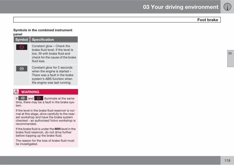
03 Your driving environment
Foot brake
03
119
Symbols in the combined instrument
panel
Symbol Specification
Constant glow – Check thebrake fluid level. If the level islow, fill with brake fluid andcheck for the cause of the brakefluid loss.
Constant glow for 2 secondswhen the engine is started –There was a fault in the brakesystem's ABS function whenthe engine was last running.
WARNING
If and illuminate at the sametime, there may be a fault in the brake sys-tem.
If the level in the brake fluid reservoir is nor-mal at this stage, drive carefully to the near-est workshop and have the brake systemchecked - an authorised Volvo workshop isrecommended.
If the brake fluid is under the MIN level in thebrake fluid reservoir, do not drive furtherbefore topping up the brake fluid.
The reason for the loss of brake fluid mustbe investigated.

03 Your driving environment
Hill Descent Control (HDC)
03
120
General1
HDC can be compared to an automatic enginebrake. When you release the accelerator ondownhill gradients the car is normally brakedby means of the engine striving for low engineidling speeds, so-called engine braking. Butthe steeper the road and the more load there isin the car, the faster the car rolls despite enginebraking. In order to then reduce speed thedriver has to assist using the footbrake.
The function makes it possible to increase/reduce speed on steep downhill gradients, witha foot only on the accelerator pedal, withoutusing the footbrake. The sensitivity of theaccelerator pedal decreases and becomesmore precise by means of the full actuation ofthe pedal being restricted to adjusting enginespeed within a limited range. The brake systembrakes itself and provides the car with a lowand even speed, so allowing the driver to fullyfocus on steering.
HDC is particularly helpful on steep gradientswith an uneven road surface and slippery sec-tions. E.g. when launching a boat on a trailerfrom a ramp.
WARNING
HDC does not work in all situations, but isinstead only intended to be supplementaryassistance.
The driver always has ultimate responsibilitythat the car is driven safely.
Function
HDC is engaged or disengaged using a switchon the centre console. An indicator lamp in thebutton illuminates when the function isswitched on. When HDC is operating the
symbol illuminates and the displayshows Hill descent control ON.
The function only operates in first gear positionand in reverse gear. For an automatic gearbox,gear position 1 must be selected, which isshown with the figure 1 in the trip computerdisplay, see page 113.
NOTE
HDC cannot be activated in an automaticgearbox with the gear selector in positionD.
Operation
HDC allows the car to roll at a maximum of10 km/h forwards with engine braking and7 km/h backwards. However, any speed withinthe gear's speed register can be selected usingthe accelerator pedal. When the acceleratorpedal is released, the car is braked quickly to10 or 7 km/h respectively, irrespective of thehill's gradient and without the need for the foot-brake.
The brake lights come on automatically whenthe function is operating. The driver can brakeor stop the car at any time by using the foot-brake.
HDC is deactivated:
1 HDC is only available on the XC70.
03 Your driving environment
Hill Descent Control (HDC)
03
121
• with the on/off button on the centre con-sole
• if a gear higher than 1 is selected on amanual gearbox
• if a gear higher than 1 is selected on anautomatic gearbox, or if the gear selectoris moved to position D.
The function can be disengaged at any time. Ifit takes place on a steep downhill gradient thenthe braking effect will not release directly, butslowly instead.
NOTE
With HDC activated you may experience adelay between acceleration pedal activationand engine response.

03 Your driving environment
Parking brake
03
122
Parking brake, electric
Function
A faint electric motor noise can be heard whenthe parking brake is being applied. The noisecan also be heard during the automatic func-tion checking of the parking brake.
If the car is stationary when the parking brakeis applied then it only acts on the rear wheels.If it is applied when the car is moving then thenormal foot brake is used, i.e. the brake actson all four wheels. Brake function changes overto the rear wheels when the car is almost sta-tionary.
Low battery voltage
If the battery voltage is too low then the parkingbrake can neither be released nor applied.Connect a donor battery if the battery voltageis too low, see page 111.
Applying the parking brake
Parking brake control.
1. Press the foot brake pedal down firmly.
2. Press the control.
3. Release the foot brake pedal and makesure that the car is at a standstill position.
• When parking the vehicle, always engage1st gear (for manual gearbox) or put thegear selector in position P (for automaticgearbox).
The symbol in the combined instru-ment panel flashes until the parking
brake is fully applied. When the symbol illumi-nates the parking brake is applied.
In an emergency the parking brake can beapplied when the vehicle is moving by depress-ing the control. When the control is released or
the accelerator pedal is depressed the brakingis interrupted.
NOTE
In the event of emergency braking at speedsabove 10 km/h a signal sounds during thebraking procedure.
Parking on a hill
If the car is parked facing uphill; turn the wheelsaway from the kerb.
If the car is parked facing downhill, turn thewheels towards the kerb.
WARNING
Get into the habit of always applying theparking brake when parking on a slope -leaving the car in gear, or in P if it has auto-matic transmission, is not sufficient to holdthe car in all situation.
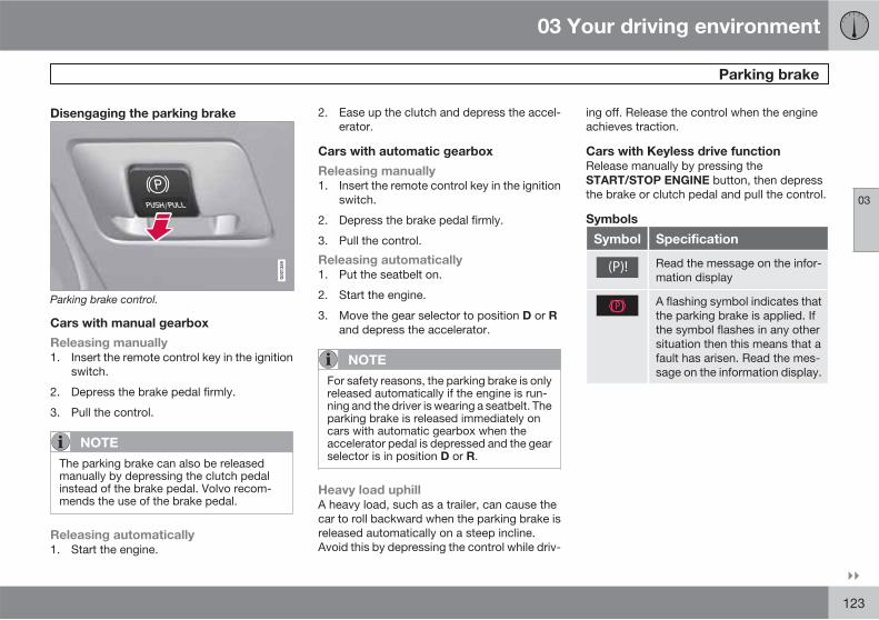
03 Your driving environment
Parking brake
03
��
123
Disengaging the parking brake
Parking brake control.
Cars with manual gearbox
Releasing manually
1. Insert the remote control key in the ignitionswitch.
2. Depress the brake pedal firmly.
3. Pull the control.
NOTE
The parking brake can also be releasedmanually by depressing the clutch pedalinstead of the brake pedal. Volvo recom-mends the use of the brake pedal.
Releasing automatically
1. Start the engine.
2. Ease up the clutch and depress the accel-erator.
Cars with automatic gearbox
Releasing manually
1. Insert the remote control key in the ignitionswitch.
2. Depress the brake pedal firmly.
3. Pull the control.
Releasing automatically
1. Put the seatbelt on.
2. Start the engine.
3. Move the gear selector to position D or Rand depress the accelerator.
NOTE
For safety reasons, the parking brake is onlyreleased automatically if the engine is run-ning and the driver is wearing a seatbelt. Theparking brake is released immediately oncars with automatic gearbox when theaccelerator pedal is depressed and the gearselector is in position D or R.
Heavy load uphill
A heavy load, such as a trailer, can cause thecar to roll backward when the parking brake isreleased automatically on a steep incline.Avoid this by depressing the control while driv-
ing off. Release the control when the engineachieves traction.
Cars with Keyless drive function
Release manually by pressing theSTART/STOP ENGINE button, then depressthe brake or clutch pedal and pull the control.
Symbols
Symbol Specification
Read the message on the infor-mation display
A flashing symbol indicates thatthe parking brake is applied. Ifthe symbol flashes in any othersituation then this means that afault has arisen. Read the mes-sage on the information display.

03 Your driving environment
Parking brake
03
124
Messages
Park brake not fully released - A fault is pre-venting the parking brake from being released.Visit a workshop - an authorised Volvo work-shop is recommended. A warning signalsounds if you pull away with this error mes-sage.
Parking brake not applied - A fault is pre-venting the parking brake from being applied.Try to apply and release. Visit a workshop if themessage remains - a Volvo workshop is rec-ommended.
The message is also illuminated on cars withmanual gearbox when the car is driven at lowspeed with the door open in order to alert thedriver that the parking brake may have beenunintentionally disengaged.
Parking brake Service required - A fault hasarisen. Visit a workshop if the fault persists - aVolvo workshop is recommended.
If the car has to be parked before the fault hasbeen rectified then the wheels must be turnedas if parking on a hill and 1st gear engaged(manual gearbox) or the gear selector must bein position P (automatic gearbox).
Replacing the brake linings
The rear brake linings must be replaced at aworkshop due to the design of the electricparking brake - an authorised Volvo workshopis recommended.

03 Your driving environment
HomeLink *
03
��
* Option/accessory, for more information, see Introduction. 125
General
HomeLink is a programmable remote controlwhich can control up to three different devices(e.g. garage door, alarm system, outdoor light-ing and indoor lighting etc.) and in doing soreplace their remote controls. HomeLink issupplied built into the left-hand sun visor.
The HomeLink panel consists of three pro-grammable buttons and one indicator lamp.
NOTE
HomeLink is designed not to work if the caris locked from the outside.
Save the original remote controls for futureprogramming (e.g. when switching toanother car).
Delete the button programming when thecar is to be sold.
Metallic sun visors should not be used incars fitted with HomeLink . This may havean adverse effect on its function.
Operation
When HomeLink is fully programmed it can beused in place of the separate original remotecontrols.
Depress the programmed button to activatethe garage door, alarm system etc. The indi-cator lamp illuminates for the time that the but-ton is kept depressed.
NOTE
If the ignition is not activated, HomeLinkwill work for 30 minutes after the driver'sdoor has been opened.
The original remote controls can of course beused in parallel with HomeLink .
WARNING
If HomeLink is used to operate a garagedoor or gate, ensure that nobody is in thevicinity of the door or gate while it is inmotion.
Do not use the HomeLink remote controlfor any garage door that does not havesafety stop and safety reverse. The garagedoor must react immediately when itdetects that something is preventing itsmovement, and stop directly and reverse. Agarage door without these characteristicscould cause personal injury. For furtherinformation - contact the supplier via theInternet: www.homelink.com.
Programming for the first time
The first step erases the memory inHomeLink and must not be carried out whenonly one individual button is being reprogram-med.
1. Depress the two outer buttons and do notrelease until the indicator lamp starts toflash after approx. 20 seconds. The flash-ing indicates that HomeLink is set in"learn mode" and is ready to be pro-grammed.
2. Position the original remote control5-30 cm from HomeLink . Monitor the indi-cator lamp.

03 Your driving environment
HomeLink *
03
126 * Option/accessory, for more information, see Introduction.
The particular distance that is requiredbetween the original remote control andHomeLink depends on the programmingof the device in question. Perhaps severalattempts will be required at different dis-tances. Maintain each position for approx.15 seconds before trying a new one.
3. Depress the button for the original remotecontrol and the button to be programmedon HomeLink simultaneously. Do notrelease the buttons until the indicator lamphas changed over from slow to rapid flash-ing. The rapid flashing indicates successfulprogramming.
4. Test the programming by depressing theprogrammed button on HomeLink andwatching the indicator lamp:
• Constant glow: The indicator lamp illu-minates with a constant glow when thebutton is kept depressed, this indicatesthat the programming is complete. Thegarage door, gate or similar should nowbe activated when the programmedHomeLink button is depressed.
• Glow not constant: The indicator lampflashes quickly for approx. 2 secondsand then changes over to a constantglow for approx. 3 seconds. This proc-
ess is repeated for approx. 20 secondsand indicates that the device has a "roll-ing code". The garage door, gate or sim-ilar is not activated when the pro-grammed HomeLink button isdepressed. Continue the programmingin accordance with the following.
5. Locate the "programming button1" on thereceiver for the garage door for example,normally located close to the antenna'sbracket on the receiver. If you have diffi-culty in finding the button - consult thesupplier's manual, or contact the suppliervia the Internet: www.homelink.com.
6. Depress and release the "programmingbutton". The button flashes forapprox. 30 seconds and the next step mustbe carried out within this period.
7. Depress the programmed button onHomeLink , while the "programming but-ton" is still flashing, keep it depressed forapprox. 3 seconds and then release.Repeat the press/hold/release sequenceup to 3 times to conclude the program-ming.
Programming individual buttons
To reprogram an individual button, proceed inaccordance with the following:
1. Depress the required button onHomeLink and do not release until step 3has been completed.
2. When the indicator lamp on HomeLinkstarts to flash, after approx. 20 seconds,position the original remote control5-30 cm from HomeLink . Monitor the indi-cator lamp.
The particular distance that is requiredbetween the original remote control andHomeLink depends on the programming ofthe device in question. Perhaps severalattempts will be required at different dis-tances. Maintain each position for approx.15 seconds before trying a new one.
3. Depress the button on the original remotecontrol. The indicator lamp will start toflash. When the flashing has changed overfrom a slow to a rapid flashing - releaseboth buttons. The rapid flashing indicatessuccessful programming.
4. Test the programming by depressing theprogrammed button on HomeLink andwatching the indicator lamp:
1 Button designation and colour vary depending on manufacturer.

03 Your driving environment
HomeLink *
03
* Option/accessory, for more information, see Introduction. 127
• Constant glow: The indicator lamp illu-minates with a constant glow when thebutton is kept depressed, this indicatesthat the programming is complete. Thegarage door, gate or similar should nowbe activated when the programmedHomeLink button is depressed.
• Glow not constant: The indicator lampflashes quickly for approx. 2 secondsand then changes over to a constantglow for approx. 3 seconds. This proc-ess is repeated for approx. 20 secondsand indicates that the device has a "roll-ing code". The garage door, gate or sim-ilar is not activated when the pro-grammed HomeLink button isdepressed. Continue the programmingin accordance with the following.
5. Locate the "programming button2" on thereceiver for the garage door for example,normally located close to the antenna'sbracket on the receiver. If you have diffi-culty in finding the button - consult thesupplier's manual, or contact the suppliervia the Internet: www.homelink.com.
6. Depress and release the "programmingbutton". The button flashes for approx. 30seconds and the next step must be carriedout within this period.
7. Depress the programmed button onHomeLink , while the "programming but-ton" is still flashing, keep it depressed forapprox. 3 seconds and then release.Repeat the press/hold/release sequenceup to 3 times to conclude the program-ming.
Erasing programming
It is only possible to erase the programming forall the buttons on HomeLink , not for individualbuttons.
� Depress the two outer buttons and do notrelease until the indicator lamp starts toflash after approx. 20 seconds.> HomeLink is now set in so-called
"learn mode" and is ready to be pro-grammed once more, see page 125.
2 Button designation and colour vary depending on manufacturer.
128 * Option/accessory, for more information, see Introduction.
Menus and messages........................................................................... 130Climate control...................................................................................... 137Fuel-driven engine block heaterand passenger compartment heater*................................................... 144Additional heater*.................................................................................. 147Audio system........................................................................................ 148RSE - Rear Seat Entertainment system - Dual Screen* ....................... 161Trip computer........................................................................................ 166DSTC – Stability and traction control system....................................... 168Adapting driving characteristics........................................................... 170Cruise control*...................................................................................... 171Adaptive cruise control*........................................................................ 173Distance Alert*...................................................................................... 181Collision Warning with Auto Brake*...................................................... 184Driver Alert System – DAC*................................................................... 190Driver Alert System - LDW*................................................................... 193Park assist syst*.................................................................................... 196BLIS* – Blind Spot Information System................................................ 199Comfort inside the passenger compartment........................................ 202Bluetooth handsfree*............................................................................ 205Built-in phone*...................................................................................... 210
COMFORT AND DRIVING PLEASURE

04 Comfort and driving pleasure
Menus and messages
04
130 * Option/accessory, for more information, see Introduction.
Operation
Some of the car's functions do not have sep-arate function keys, but instead can beadjusted/activated/deactivated via a menusystem.
Navigation in the menus is carried out usingsome of the centre console buttons or with thesteering wheel's right-hand keypad.
Many functions are standard, some areoptional. The range varies depending on mar-ket.
Centre console controls
Centre console with information display and con-trols for menus.
Numerical keypad 1–9
Navigation button – scrolls and selectsamong menu options
MENU – leads to the menu system
EXIT – leads back one step in the menustructure. A long press leads out from themenu system.
ENTER – selects menu options
Steering wheel keypad*
ENTER
EXIT
Navigation buttons – up/down.
If the steering wheel keypad has ENTER andEXIT then these buttons, and the navigationbuttons, have the same functions as the con-trols in the centre console.
Search paths
Current menu level is shown at the top right ofthe centre console display. Search paths to themenu system functions are described in thismanual in the following form:
Car settings Lock settings
The following is an example of how a functioncan be accessed and adjusted using the centreconsole buttons:
1. Press MENU.
2. Scroll to the desired menu, e.g. Car
settings, with the navigation buttons andpress ENTER - a submenu opens.
3. Scroll to Lock settings and pressENTER - a new submenu opens.
4. Scroll to Doors unlock and pressENTER - a submenu of selectable func-tions opens.
5. Choose between the options and pressENTER - a cross is marked in the option'sempty box.
6. Exit the programming by backing out of themenus incrementally with short presses onEXIT or with one long press.
The navigation buttons can be used instead ofENTER and EXIT when navigating in the menu

04 Comfort and driving pleasure
Menus and messages
04
��
* Option/accessory, for more information, see Introduction. 131
hierarchy. The right-hand arrow is equal toENTER and the left-hand arrow to EXIT.
The menu options are numbered and can alsobe selected directly with the numerical keypad(only 1–9).
Menu overview
The phone and audio sources each have sep-arate main menus. An audio source main menu(e.g. CD) can only be accessed when that par-ticular audio source is active, see page 149.
The following menu options are included inMain menu:
Car Key memory
Seat & mirror positions*
Car settings
Information
Light settings
Lock settings
Reduced guard1
Tyre pressure *
Side mirror settings *
Collision warning settings *
Parking camera settings *
Lane departure warning *
Steering force level *
Unit settings
Driver Alert on
Climate settings
Automatic blower adjust
Recirculation timer
Auto. rear defroster
Seat heating time limit.
Seat heating off during starting
Reset climate settings
Main menu AM
Audio settings
Sound stage
Equalizer front
Equalizer rear
Auto. volume control
Reset all audio settings
Main menu FM
FM settings
News
TP (Traffic information)
Radio text
PTY (Program type)
Advanced radio settings
Audio settings2
Main menu DAB * 3
Main menu CD
Random
Off
Folder4
Disc4
Single disc5
All discs 5
CD settings
Track information *
1 Available in certain models.2 For submenus, see "Main menu AM/Audio settings".3 See page 158 .4 Only in systems that allow the playback of MP3 and WMA format audio files.5 Only in systems with CD changer.

04 Comfort and driving pleasure
Menus and messages
04
132 * Option/accessory, for more information, see Introduction.
News
TP (Traffic information)
Audio settings 2
Main menu AUX
AUX input volume
Audio settings 2
Main menu USB
USB settings
Track information
News
TP (Traffic information)
Audio settings 2
Main menu iPod
iPod settings
News
TP (Traffic information)
Audio settings 2
Track information
Main menu, Bluetooth6
Call register
Last 10 missed calls
Last 10 received calls
Last 10 dialled calls
Phone book
Search
Copy fr. mobile phone
Bluetooth *
Change phone7
Connect phone8
Remove phone
Connect fr. mobile phone
Bluetooth info. for the car
Call options
Automatic answer
Voice mail number
Phone settings
Sounds and volume
Synchronise phone book
Main menu, Bluetooth9
Call register
Last 10 missed calls
Last 10 received calls
Last 10 dialled calls
Phone book
Search
Copy fr. mobile phone
Bluetooth *
Connect phone10
Remove phone
Connect fr. mobile phone
Bluetooth info. for the car
Call options
Automatic answer
2 For submenus, see "Main menu AM/Audio settings".6 Applies to cars that do not have built-in phone.7 Only shown if a phone is connected.8 Only shown if no phone is connected.9 Applies to cars with built-in phone and BluetoothTM handsfree.10Only shown if no phone is connected.

04 Comfort and driving pleasure
Menus and messages
04
��
133
Voice mail number
Change phone
Car phone
Add phone
Added phones11
Phone settings
Sounds and volume
Synchronise phone book
Main menu, built-in phone
Call register
Last 10 missed calls
Last 10 received calls
Last 10 dialled calls
Erase list
Call duration
Phone book
Search
New contact
Copy all
Speed-dial
Erase SIM
Erase phone
Memory status
Messages
Read
Write new
Delete all messages
Message settings
Call options
Send my number
Call waiting
Automatic answer
Auto redial
Voice mail number
Diversions
Change phone9
Car phone
Add phone
Added phones11
Phone settings
Network selection
SIM security
Edit PIN code
Sounds and volume
IDIS
Reset Phone settings
11A maximum of 5 phones.9 Applies to cars with built-in phone and BluetoothTM handsfree.
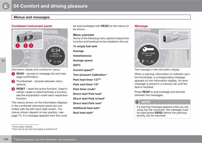
04 Comfort and driving pleasure
Menus and messages
04
134 * Option/accessory, for more information, see Introduction.
Combined instrument panel
Information display and controls for menus.
READ – access to message list and mes-sage confirmation.
Thumbwheel – browse between menuoptions.
RESET – reset the active function. Used incertain cases to select/activate a function,see the explanation under each respectivefunction.
The menus shown on the information displaysin the combined instrument panel are con-trolled with the left-hand stalk switch. Themenus shown depend on key position, seepage 74. If a message appears then this must
be acknowledged with READ for the menus tobe shown.
Menu overview
Some of the following menu options require thefunction and hardware to be installed in the car.
To empty fuel tank
Average
Instantaneous
Average speed
DSTC
Current speed12
Tyre pressure Calibration *
Park heat timer 1/213*
Park vent timer 1/2*
Park timer mode*
Direct start Park heat*
Direct start Park el.heat*
Direct start Park vent*
Additional heat auto*
Rest heat start*
Message
Text message in the information display.
When a warning, information or indicator sym-bol illuminates, a corresponding messageappears on the information display. An errormessage is stored in a memory list until thefault is rectified.
Press READ to acknowledge and browsebetween the messages.
NOTE
If a warning message appears while you areusing the trip computer, the message mustbe read (press READ) before the previousactivity can be resumed.
12Only certain markets.13Can only be set when the engine is switched off.
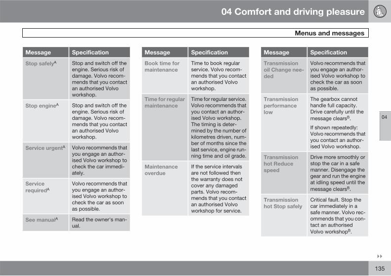
04 Comfort and driving pleasure
Menus and messages
04
��
135
Message Specification
Stop safelyA Stop and switch off theengine. Serious risk ofdamage. Volvo recom-mends that you contactan authorised Volvoworkshop.
Stop engineA Stop and switch off theengine. Serious risk ofdamage. Volvo recom-mends that you contactan authorised Volvoworkshop.
Service urgentA Volvo recommends thatyou engage an author-ised Volvo workshop tocheck the car immedi-ately.
Service
requiredAVolvo recommends thatyou engage an author-ised Volvo workshop tocheck the car as soonas possible.
See manualA Read the owner's man-ual.
Message Specification
Book time for
maintenance
Time to book regularservice. Volvo recom-mends that you contactan authorised Volvoworkshop.
Time for regular
maintenance
Time for regular service.Volvo recommends thatyou contact an author-ised Volvo workshop.The timing is deter-mined by the number ofkilometres driven, num-ber of months since thelast service, engine run-ning time and oil grade.
Maintenance
overdue
If the service intervalsare not followed thenthe warranty does notcover any damagedparts. Volvo recom-mends that you contactan authorised Volvoworkshop for service.
Message Specification
Transmission
oil Change nee-
ded
Volvo recommends thatyou engage an author-ised Volvo workshop tocheck the car as soonas possible.
Transmission
performance
low
The gearbox cannothandle full capacity.Drive carefully until themessage clearsB.
If shown repeatedly:Volvo recommends thatyou contact an author-ised Volvo workshop.
Transmission
hot Reduce
speed
Drive more smoothly orstop the car in a safemanner. Disengage thegear and run the engineat idling speed until themessage clearsB.
Transmission
hot Stop safely
Critical fault. Stop thecar immediately in asafe manner. Volvo rec-ommends that you con-tact an authorisedVolvo workshopB.

04 Comfort and driving pleasure
Menus and messages
04
136
Message Specification
Temporarily
OFFAA function has beentemporarily switchedoff and is reset auto-matically while drivingor after starting again.
Low battery
Power save
mode
The audio system isswitched off to saveenergy. Charge the bat-tery.
A Part of message, shown together with information on wherethe problem has arisen.
B For more messages concerning automatic transmission, seepage 115.
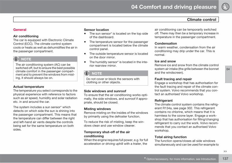
04 Comfort and driving pleasure
Climate control
04
��
* Option/accessory, for more information, see Introduction. 137
General
Air conditioning
The car is equipped with Electronic ClimateControl (ECC). The climate control systemcools or heats as well as dehumidifies the air inthe passenger compartment.
NOTE
The air conditioning system (AC) can beswitched off, but to ensure the best possibleclimate comfort in the passenger compart-ment and to prevent the windows from mist-ing, it should always be on.
Actual temperature
The temperature you select corresponds to thephysical experience with reference to factorssuch as air speed, humidity and solar radiationetc. in and around the car.
The system includes a sun sensor* whichdetects on which side the sun is shining intothe passenger compartment. This means thatthe temperature can differ between the rightand left-hand air vents despite the controlsbeing set for the same temperature on bothsides.
Sensor location
• The sun sensor* is located on the top sideof the dashboard.
• The temperature sensor for the passengercompartment is located below the climatecontrol panel.
• The outside temperature sensor is locatedon the door mirror.
• The humidity sensor* is located in the inte-rior rearview mirror.
NOTE
Do not cover or block the sensors withclothing or other objects.
Side windows and sunroof
To ensure that the air conditioning works opti-mally, the side windows, and sunroof if appro-priate, should be closed.
Misting windows
Remove misting on the insides of the windowsby primarily using the defroster function.
To reduce the risk of misting, keep the win-dows clean and use window cleaner.
Temporary shut-off of the air
conditioning
When the engine requires full power, e.g. for fullacceleration or driving uphill with a trailer, the
air conditioning can be temporarily switchedoff. There may then be a temporary increase intemperature in the passenger compartment.
Condensation
In warm weather, condensation from the airconditioning may drip under the car. This isnormal.
Ice and snow
Remove ice and snow from the climate controlsystem air intake (the grille between the bonnetand the windscreen).
Fault tracing and repair
Engage a workshop that has authorisation forthe fault tracing and repair of the climate con-trol system. Volvo recommends that you con-tact an authorised Volvo workshop.
Refrigerant
The climate control system contains the refrig-erant R134a, see page 302. This refrigerantcontains no chlorine, which means that it isharmless to the ozone layer. Engage a work-shop that has authorisation for filling/changingrefrigerant to carry out the work. Volvo recom-mends that you contact an authorised Volvoworkshop.
Total airing function
The function opens/closes all side windowssimultaneously and can be used for example to
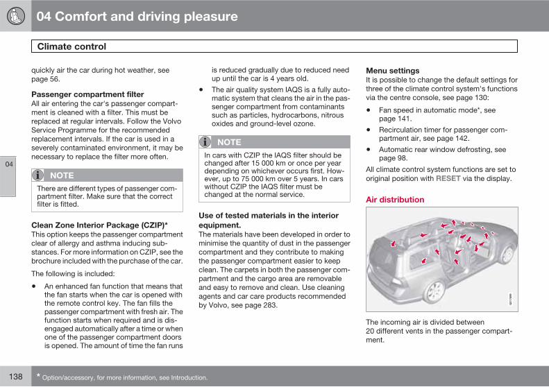
04 Comfort and driving pleasure
Climate control
04
138 * Option/accessory, for more information, see Introduction.
quickly air the car during hot weather, seepage 56.
Passenger compartment filter
All air entering the car's passenger compart-ment is cleaned with a filter. This must bereplaced at regular intervals. Follow the VolvoService Programme for the recommendedreplacement intervals. If the car is used in aseverely contaminated environment, it may benecessary to replace the filter more often.
NOTE
There are different types of passenger com-partment filter. Make sure that the correctfilter is fitted.
Clean Zone Interior Package (CZIP)*
This option keeps the passenger compartmentclear of allergy and asthma inducing sub-stances. For more information on CZIP, see thebrochure included with the purchase of the car.
The following is included:
• An enhanced fan function that means thatthe fan starts when the car is opened withthe remote control key. The fan fills thepassenger compartment with fresh air. Thefunction starts when required and is dis-engaged automatically after a time or whenone of the passenger compartment doorsis opened. The amount of time the fan runs
is reduced gradually due to reduced needup until the car is 4 years old.
• The air quality system IAQS is a fully auto-matic system that cleans the air in the pas-senger compartment from contaminantssuch as particles, hydrocarbons, nitrousoxides and ground-level ozone.
NOTE
In cars with CZIP the IAQS filter should bechanged after 15 000 km or once per yeardepending on whichever occurs first. How-ever, up to 75 000 km over 5 years. In carswithout CZIP the IAQS filter must bechanged at the normal service.
Use of tested materials in the interior
equipment.
The materials have been developed in order tominimise the quantity of dust in the passengercompartment and they contribute to makingthe passenger compartment easier to keepclean. The carpets in both the passenger com-partment and the cargo area are removableand easy to remove and clean. Use cleaningagents and car care products recommendedby Volvo, see page 283.
Menu settings
It is possible to change the default settings forthree of the climate control system's functionsvia the centre console, see page 130:
• Fan speed in automatic mode*, seepage 141.
• Recirculation timer for passenger com-partment air, see page 142.
• Automatic rear window defrosting, seepage 98.
All climate control system functions are set tooriginal position with RESET via the display.
Air distribution
G01
7699
The incoming air is divided between20 different vents in the passenger compart-ment.
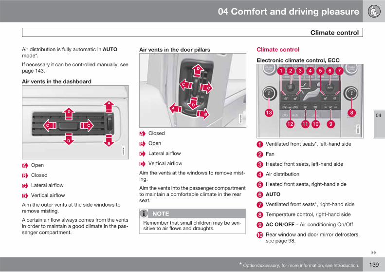
04 Comfort and driving pleasure
Climate control
04
��
* Option/accessory, for more information, see Introduction. 139
Air distribution is fully automatic in AUTO
mode*.
If necessary it can be controlled manually, seepage 143.
Air vents in the dashboard
G02
1367
Open
Closed
Lateral airflow
Vertical airflow
Aim the outer vents at the side windows toremove misting.
A certain air flow always comes from the ventsin order to maintain a good climate in the pas-senger compartment.
Air vents in the door pillars
G02
1368
Closed
Open
Lateral airflow
Vertical airflow
Aim the vents at the windows to remove mist-ing.
Aim the vents into the passenger compartmentto maintain a comfortable climate in the rearseat.
NOTE
Remember that small children may be sen-sitive to air flows and draughts.
Climate control
Electronic climate control, ECC
Ventilated front seats*, left-hand side
Fan
Heated front seats, left-hand side
Air distribution
Heated front seats, right-hand side
AUTO
Ventilated front seats*, right-hand side
Temperature control, right-hand side
AC ON/OFF – Air conditioning On/Off
Rear window and door mirror defrosters,see page 98.

04 Comfort and driving pleasure
Climate control
04
140 * Option/accessory, for more information, see Introduction.
Max. defroster
Recirculation/Air quality system
Temperature control, left-hand side
Operation
Ventilated front seats*
Ventilated front seats can onlybe specified when ECC isinstalled in the car. The venti-lation system consists of fansin the seats and backreststhat draw air through the seatupholstery. The cooling effect
increases the cooler the passenger compart-ment air becomes.
The ventilation is regulated from the climatecontrol and takes seat temperature, solar radi-ation and outside temperature into considera-tion.
The ventilation can be used at the same timeas seat heating. For example, the function canbe used to dry damp from clothing.
The ventilation system can be activated whenthe engine is running. There are three comfortlevels that produce different cooling and dehu-midification outputs:
• Comfort level III: press the button once formaximum output – three lamps illuminate.
• Comfort level II: press the button twice forlower output – two lamps illuminate.
• Comfort level I: press the button threetimes for the lowest output – one lamp illu-minates.
Press the button four times to switch off thefunction – no lamps illuminate.
NOTE
The seat ventilation should be used carefullyby people sensitive to draughts. Comfortlevel I is recommended for long-term use.
IMPORTANT
The seat ventilation cannot be started whenpassenger compartment temperature isbelow 5 °C. This is to avoid chilling anyonesitting in the seat.
Fan
Turn the knob to increase ordecrease fan speed. If AUTO
is selected then fan speed isregulated automatically. Thepreviously set fan speed isdisengaged.
NOTE
If the fan is fully disengaged the air condi-tioning is not engaged which may result in arisk of misting windows.
Heated seats
Front seats
Press the button once for thehighest heat level – threelamps illuminate.
Press the button twice for alower heat level – two lampsilluminate.
Press the button three times for the lowest heatlevel – one lamp illuminates.
Press the button four times to switch off theheat – no lamps illuminate.
The heating is normally switched off at start up.If the heating has been switched on then it isswitched off automatically when the engine isswitched off. Automatic start of heating can beactivated/deactivated in the menu under:Climate settings Seat heating off during
starting

04 Comfort and driving pleasure
Climate control
04
��
141
Seat heating is switched off automatically aftera while. The function can be deactivated/acti-vated in the menu under: Climate settings
Seat heating time limit.
For a description of the menu system, seepage 130.
WARNING
The heated seat should not be used by peo-ple who find it difficult to perceive tempera-ture increase because of sensory loss or forany reason have difficulty in managing touse the control of the heated seat. Other-wise, burn injuries may arise.
Air distribution
The figure consists of threebuttons. When the buttonsare pressed a lamp in front ofthe respective part of the fig-ure illuminates and showswhich air distribution isselected, see page 143.
Auto
The Auto function automati-cally regulates temperature,air conditioning, fan speed,recirculation, and air distribu-tion.
If you select one or more manual functions, theother functions continue to be controlled auto-matically. The air quality sensor is engaged andall manual settings are switched off whenAUTO is pressed. The display shows AUTO
CLIMATE.
Fan speed in automatic mode can be set upunder the menu: Climate settings
Automatic blower adjust. Choose betweenLow, Normal or High:
• Low - Automatic fan control. Low airflowis prioritised.
• Normal - Automatic fan control.
• High - Automatic fan control. A moreintense airflow is prioritised.
For a description of the menu system, seepage 130.
Temperature control
The temperatures on thedriver and passenger sidescan be set independently.
When the car is started, themost recent setting isresumed.
NOTE
Heating or cooling cannot be hastened byselecting a higher/lower temperature thanthe actual temperature required.
AC – Air conditioning on/off
ON: The air conditioning iscontrolled by the system'sAuto function. This way,incoming air is cooled anddehumidified.
OFF: When the defrosterfunction is activated the air conditioning isswitched on automatically (can be switched offusing the AC button).
Defroster
Used to quickly remove mist-ing and ice from the wind-screen and side windows. Airflowing to the windows. Thelight in the defroster buttonilluminates when the functionis active.
The following also takes place in order to pro-vide maximum dehumidification in the passen-ger compartment:

04 Comfort and driving pleasure
Climate control
04
142 * Option/accessory, for more information, see Introduction.
• the air conditioning is automaticallyengaged
• recirculation and the air quality system areautomatically disengaged.
The air conditioning can be disengaged man-ually using the AC button. When the defrosterfunction is switched off the climate control sys-tem returns to the previous settings.
Recirculation/Air quality system
Recirculation
When recirculation isengaged the right-handorange light in the button illu-minates. The function isselected to shut out bad air,exhaust gases etc. from thepassenger compartment. The
air in the passenger compartment is recircula-ted, i.e. no outside air is taken into the car whenthis function is activated.
NOTE
If the air in the car recirculates for too long,there is a risk of misting on the insides of thewindows.
Timer
With the timer function activated the systemwill exit manually activated recirculation mode
according to a time that depends on the out-side temperature. This reduces the risk of ice,misting and bad air. Activate/deactivate thefunction under Climate settings
Recirculation timer. For a description of themenu system, see page 130.
NOTE
When Defroster is selected, recirculation isalways deactivated.
Air quality system*
The air quality system sepa-rates gases and particles toreduce the levels of odoursand pollution in the passengercompartment. If the outsideair is contaminated then theair intake is closed and the air
is recirculated. When the AUTO button isdepressed the air quality sensor is alwaysengaged.
Activating recirculation/air quality
sensor
Switch between the threefunctions by pressing the but-ton repeatedly.
• The left-hand orange lamp illuminates – theair quality sensor is disengaged. There isno recirculation, only fresh air.
• The centre green lamp illuminates – recir-culation not engaged, providing it is notrequired for cooling in hot weather.
• The right-hand orange lamp illuminates –recirculation is engaged.
NOTE
The air quality sensor should always beengaged in order to obtain the best air in thepassenger compartment.
Recirculation is limited in cold weather toavoid misting.
If the insides of the windows start mistingup, disengage the air quality sensor, and thedefroster functions for the windscreen, theside and the rear windows should also beused to demist the windows.
Activating recirculation
Switch between recirculationOn/Off by pressing the buttonrepeatedly. The lamp illumi-nates when recirculation isengaged.
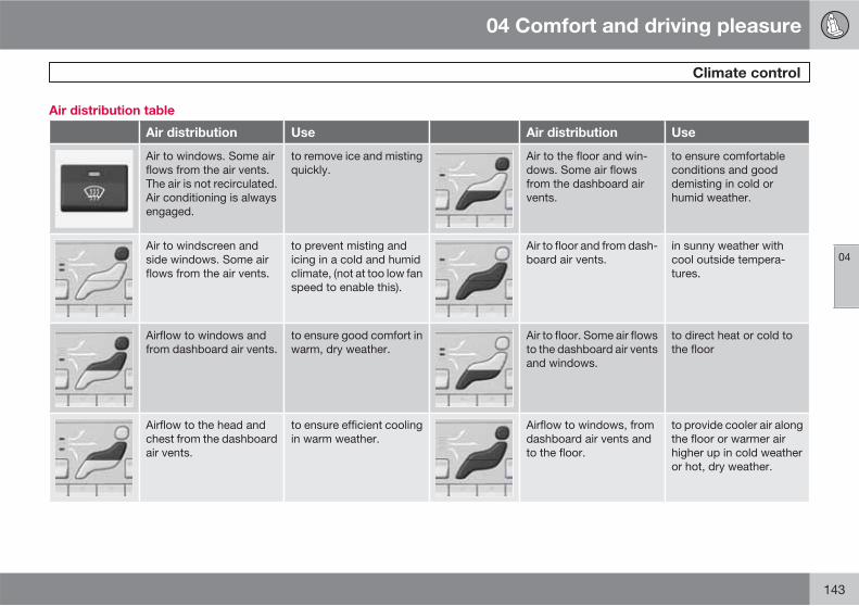
04 Comfort and driving pleasure
Climate control
04
143
Air distribution table
Air distribution Use Air distribution Use
Air to windows. Some airflows from the air vents.The air is not recirculated.Air conditioning is alwaysengaged.
to remove ice and mistingquickly.
Air to the floor and win-dows. Some air flowsfrom the dashboard airvents.
to ensure comfortableconditions and gooddemisting in cold orhumid weather.
Air to windscreen andside windows. Some airflows from the air vents.
to prevent misting andicing in a cold and humidclimate, (not at too low fanspeed to enable this).
Air to floor and from dash-board air vents.
in sunny weather withcool outside tempera-tures.
Airflow to windows andfrom dashboard air vents.
to ensure good comfort inwarm, dry weather.
Air to floor. Some air flowsto the dashboard air ventsand windows.
to direct heat or cold tothe floor
Airflow to the head andchest from the dashboardair vents.
to ensure efficient coolingin warm weather.
Airflow to windows, fromdashboard air vents andto the floor.
to provide cooler air alongthe floor or warmer airhigher up in cold weatheror hot, dry weather.

04 Comfort and driving pleasure
Fuel-driven engine block heater and passenger compartment heater*
04
144 * Option/accessory, for more information, see Introduction.
Fuel-driven heater
General information about the parking
heater
The parking heater heats the engine and pas-senger compartment and can be starteddirectly or with the timer.
Two different times can be selected using thetimer. Here, time refers to the time when the caris heated and ready. The car's electronic sys-tem calculates when heating should be startedbased on the outside temperature.
The heater cannot start if the outside tempera-ture exceeds 15 °C. At -5 °C or lower the maxi-mum running time of the parking heater is 50minutes.
WARNING
The car must be outdoors when the parkingheater is used.
NOTE
When the parking heater is active there maybe smoke from the right-hand wheel hous-ing, which is perfectly normal.
Refuelling
Warning decal on fuel filler flap.
WARNING
Fuel which spills out can be ignited. Switchoff the fuel-driven heater before starting torefuel.
Check the information display to see thatthe parking heater is switched off. When itis running, the information display showsPark heat ON.
Parking on a hill
If the car is parked on a steep hill, the front ofthe car should point downhill to ensure thatthere is a supply of fuel to the parking heater.
Battery and fuel
If the battery has insufficient charge or the fuellevel is too low, the parking heater is switchedoff automatically and a message appears onthe information display. Acknowledge the mes-sage by pressing once on the indicator stalkREAD button, see page 145.
IMPORTANT
Repeated use of the parking heater com-bined with short journeys may discharge thebattery and impair starting.
The car should be driven for the same timeas the heater is used to ensure that the car'sbattery is recharged adequately to replacethe energy consumed by the heater when itis used on a regular basis.

04 Comfort and driving pleasure
Fuel-driven engine block heater and passenger compartment heater*
04
��
* Option/accessory, for more information, see Introduction. 145
Operation
READ button
Thumbwheel
RESET button
For more information on the information dis-play and READ, see page 134.
Symbols and display messages
When one of the timer's settings orDirect start is activated, the infor-
mation symbol in the combined instrumentpanel illuminates while the information displayshows an explanatory text and a further illumi-nated symbol. The table shows symbols anddisplay texts that appear.
Sym-bol
Display Specification
G025102
Fuel
heater
ON
The heater isswitched on andrunning.
G025102
Timer is
set for
Fuel
heater
The heater's timeris activated afterthe remote controlkey has beenremoved from theignition switch andleaving the car -the engine andpassenger com-partment areheated at the settime.
G025102
Heater
stopped
Low bat-
tery
The heater hasbeen stopped bythe car's electron-ics in order to facil-itate starting theengine.
Sym-bol
Display Specification
G025102
Heater
unavail.
Low fuel
level
Setting the heateris not possible dueto fuel level beingtoo low(approx. 7 litres) -this is in order tofacilitate startingthe engine as wellas approx. 50 kmdriving.
G025102
Park
heater
Service
required
Heater not work-ing. Contact aworkshop forrepair. Volvo rec-ommends that youcontact an author-ised Volvo work-shop.
A display text clears automatically after a timeor after one press on the indicator stalkREAD button.

04 Comfort and driving pleasure
Fuel-driven engine block heater and passenger compartment heater*
04
146 * Option/accessory, for more information, see Introduction.
Direct start and immediate stop
1. Scroll with the thumbwheel to Direct start
Park heat.
2. Press RESET to select between ON andOFF.
ON: Parking heater switched on manually orwith programmed timer.
OFF: Parking heater switched off.
With the direct start of the heater it will be acti-vated for 50 minutes.
Heating of the passenger compartment willbegin as soon as the engine coolant hasreached the correct temperature.
NOTE
The car can be started and driven while theparking heater is running.
Setting the timer
The time when the car shall be used and heatedis specified with the timer.
Select between TIMER 1 and TIMER 2.
NOTE
The timer can only be programmed whenthe remote control key is in key position I,see page 74 - programming must thereforebe carried out before starting the engine.
1. Scroll with the thumbwheel to Park heat
timer 1.
2. Briefly press RESET to move to the flash-ing hours setting.
3. Select the required hour using the thumb-wheel.
4. Briefly press RESET to move to the flash-ing minutes setting.
5. Select the required minute using thethumbwheel.
6. Briefly press RESET to confirm the setting.
7. Press RESET to activate the timer.
After setting Park heat timer 1 a second starttime can be programmed with Park heat timer
2 by scrolling to it with the thumbwheel.
Set the alternative time in the same way asPark heat timer 1.
Deactivating a timer-started heater
A timer-started heater can be switched offmanually before the set time has elapsed. Pro-ceed as follows:
1. Press READ.
2. Use the thumbwheel to scroll to the textPark heat timer 1 or 2.> The text ON flashes on the display.
3. Press RESET.> The text OFF is shown with a constant
glow and the heater is switched OFF.
A timer-started heater can be switched off inaccordance with the instructions in the section"Direct start and immediate stop", seepage 146.
Clock/timer
The heater's time is connected to the car'sclock.
NOTE
All timer programming will be cleared if thecar's clock is reset.

04 Comfort and driving pleasure
Additional heater*
04
* Option/accessory, for more information, see Introduction. 147
General information about theadditional heater
In cold climate zones1 an additional heater maybe required to obtain the correct operatingtemperature in the engine and to obtain suffi-cient heating in the passenger compartment.
Fuel-driven additional heater
A fuel-driven additional heater is fitted in carswith diesel engines.
The heater starts automatically when extraheat is required when the engine is running.
The heater is switched off automatically whenthe correct temperature is reached or when theengine is switched off.
NOTE
When the additional heater is active theremay be smoke from the right-hand wheelhousing which is perfectly normal.
Auto mode or shutdown
The additional heater can be switched off forshort distances if required.
READ button
Thumbwheel
RESET button
1. Scroll with the thumbwheel to Additional
heat auto.
2. Press RESET to select between ON andOFF.
NOTE
The menu options are only visible in keyposition I - any adjustments must thereforebe made before starting the engine.
Passenger compartment heater*
If the additional heater is supplemented withtimer function then it can be used as a fuel-driven passenger compartment heater, seepage 144.
Electric additional heater
Cars with certain petrol engines2 have an elec-tric additional heater integrated into the car'sclimate control system.
In a semi-cold1 climate zone diesel-driven carshave an electric additional heater instead of afuel-driven version.
The heater cannot be controlled manually butis instead activated automatically after theengine has been started in outside tempera-tures below 14 °C and is switched off after theset passenger compartment temperature hasbeen reached.
1 An authorised Volvo dealer has information regarding the geographical areas concerned.2 An authorised Volvo dealer has information regarding the engines concerned.
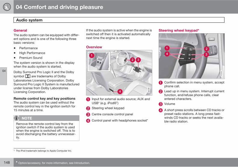
04 Comfort and driving pleasure
Audio system
04
148 * Option/accessory, for more information, see Introduction.
General
The audio system can be equipped with differ-ent options and is one of the following threebasic versions:
• Performance
• High Performance
• Premium Sound
The system version is shown in the displaywhen the audio system is started.
Dolby Surround Pro Logic II and the Dolbysymbol are trademarks of DolbyLaboratories Licensing Corporation. DolbySurround Pro Logic II System is manufacturedunder license from Dolby LaboratoriesLicensing Corporation.
Remote control key and key positions
The audio system can be used without theremote control key in the ignition switch for15 minutes at a time.
NOTE
Remove the remote control key from theignition switch if the audio system is usedwhen the engine is switched off. This is toavoid discharging the battery unnecessar-ily.
If the audio system is active when the engine isswitched off then it is activated automaticallynext time the engine is started.
Overview
Input for external audio source; AUX andUSB* (e.g. iPod 1)
Steering wheel keypad
Centre console control panel
Control panel with headphones socket*
Steering wheel keypad*
Confirm selection in menu system, acceptphone call.
Lead up in menu system. Interrupt currentfunction, end/refuse phone calls, clearentered characters.
Volume
A short press scrolls between CD tracks orpreset radio stations. A long press fast-winds CD tracks or seeks the next availa-ble radio station.
1 The iPod trademark belongs to Apple Computer Inc.

04 Comfort and driving pleasure
Audio system
04
��
* Option/accessory, for more information, see Introduction. 149
Rear control panel with headphonessocket*
Headphones with an impedance of16-32 ohm and sensitivity of 102 dB or higherare recommended for best sound reproduc-tion.
VOLUME – Volume, left and right.
Scroll/search forward and backward.
MODE - Select between AM, FM, CD,AUX, USB*(e.g. iPod ), DAB1/DAB2* andOn/Off. For connection via AUX or USB,see page 151.
Headphones sockets (3.5 mm).
Activating/deactivating
The control panel is activated with MODE.Deactivation is possible via a long press onMODE or when the engine is switched off.
Scroll/search forward and backward
Short presses on (2) are used to scroll betweenCD tracks or preset radio stations. A long pressfast-winds CD tracks or seeks the next availa-ble radio station.
Limitations
• The audio source (FM, AM, CD etc.) playedback in the speakers cannot be controlledfrom the rear control panel.
Audio functions
Centre console, controls for audio functions.
AM, FM and CD, internal audio sources
MODE - Scroll between external audiosources (AUX, USB* and DAB1/DAB2*).For connection via AUX or USB, seepage 151.
SOUND - Pushbutton and knob controlsfor adjusting the sound pattern
Navigation button
VOLUME - Volume and On/Off
Audio volume and automatic volume
control
The audio system compensates for disruptingnoises in the passenger compartment byincreasing the volume with the speed of the
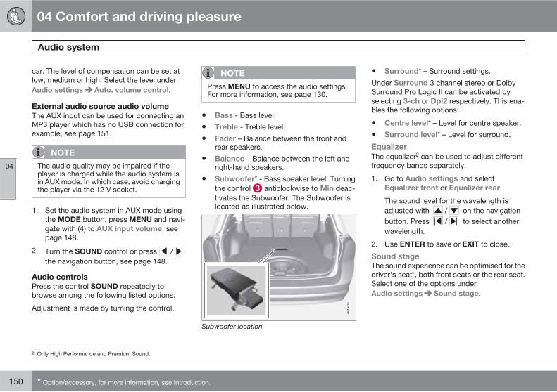
04 Comfort and driving pleasure
Audio system
04
150 * Option/accessory, for more information, see Introduction.
car. The level of compensation can be set atlow, medium or high. Select the level underAudio settings Auto. volume control.
External audio source audio volume
The AUX input can be used for connecting anMP3 player which has no USB connection forexample, see page 151.
NOTE
The audio quality may be impaired if theplayer is charged while the audio system isin AUX mode. In which case, avoid chargingthe player via the 12 V socket.
1. Set the audio system in AUX mode usingthe MODE button, press MENU and navi-gate with (4) to AUX input volume, seepage 148.
2. Turn the SOUND control or press / the navigation button, see page 148.
Audio controls
Press the control SOUND repeatedly tobrowse among the following listed options.
Adjustment is made by turning the control.
NOTE
Press MENU to access the audio settings.For more information, see page 130.
• Bass - Bass level.
• Treble - Treble level.
• Fader – Balance between the front andrear speakers.
• Balance – Balance between the left andright-hand speakers.
• Subwoofer* - Bass speaker level. Turningthe control anticlockwise to Min deac-tivates the Subwoofer. The Subwoofer islocated as illustrated below.
G01
9419
Subwoofer location.
• Surround* – Surround settings.
Under Surround 3 channel stereo or DolbySurround Pro Logic II can be activated byselecting 3-ch or Dpl2 respectively. This ena-bles the following options:
• Centre level* – Level for centre speaker.
• Surround level* – Level for surround.
Equalizer
The equalizer2 can be used to adjust differentfrequency bands separately.
1. Go to Audio settings and selectEqualizer front or Equalizer rear.
The sound level for the wavelength isadjusted with / on the navigationbutton. Press / to select anotherwavelength.
2. Use ENTER to save or EXIT to close.
Sound stage
The sound experience can be optimised for thedriver's seat*, both front seats or the rear seat.Select one of the options underAudio settings Sound stage.
2 Only High Performance and Premium Sound.

04 Comfort and driving pleasure
Audio system
04
��
* Option/accessory, for more information, see Introduction. 151
Optimum sound reproduction
The audio system is calibrated for optimumsound reproduction by means of digital signalprocessing.
This calibration takes into account loudspeak-ers, amplifiers, passenger compartmentacoustics, listener position etc. for each com-bination of car model and audio system.
There is a also a dynamic calibration that takesinto account the position of the volume control,radio reception and vehicle speed.
The controls explained in these operatinginstructions, e.g. Bass, Treble andEqualizer, are only intended for the user to beable to adapt the sound reproduction accord-ing to personal taste.
AUX, USB3 and external audio source
General
An external audio source can be connected to thecar's infotainment system via the USB connec-tion* or AUX input in the centre console.
The AUX input enables the connection of anexternal audio source, e.g. an iPod or MP3player. Read more on page 150
If you choose to connect an iPod , MP3 playeror a USB memory stick to the USB connec-tion* then you can control the audio sourceusing the car's audio controls.
Select the connection using the MODE button:
1. If USB is selected then Connect device isshown in the display.
2. Connect your iPod , MP3 player or USBmemory stick to the USB connection* inthe centre console's storage compartment(see preceding illustration).
The text Loading is shown in the display whenthe system is loading the storage media's filestructure. This may take some time.
Once loading is complete, track information isshown on the display and the desired track canbe selected.
A track can be selected in three ways:
• With the TUNING control, , see page 148.
• the navigation control's (4) right or left-hand button or, , see page 148.
• the steering wheel keypad (see page 148).
In USB or iPod mode the audio system oper-ates in an equivalent way to the CD player forplaying back music files. For more information,see page 153.
3 Only High Performance and Premium Sound.
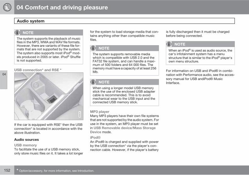
04 Comfort and driving pleasure
Audio system
04
152 * Option/accessory, for more information, see Introduction.
NOTE
The system supports the playback of musicfiles in the MP3, WMA and WAV file formats.However, there are variants of these file for-mats that are not supported by the system.The system also supports most iPod mod-els produced in 2005 or later. iPod Shuffleis not supported.
USB connection* and RSE *
If the car is equipped with RSE* then the USBconnection* is located in accordance with theabove illustration.
Audio sources
USB memory
To facilitate the use of a USB memory stick,only store music files on it. It takes a lot longer
for the system to load storage media that con-tains anything other than compatible musicfiles.
NOTE
The system supports removable mediawhich is compatible with USB 2.0 and theFAT32 file system, and can handle a maxi-mum of 500 folders and 64 000 files. Thememory must have a capacity of at least 256Mb.
NOTE
When using a longer model USB memorystick the use of the enclosed USB adaptercable is recommended. This is to avoidmechanical wear to the USB input and theconnected USB memory stick.
MP3 player
Many MP3 players have their own file systemsthat are not supported by the audio system. Foruse in the system, an MP3 player must be setin USB Removable device/Mass Storage
Device mode.
iPod
An iPod is charged and supplied with powerby the USB connection* via the player's con-nection cable. However, if the player's battery
is fully discharged then it must be chargedbefore being connected.
NOTE
When an iPod is used as audio source, thecar's infotainment system has a menustructure that is similar to the iPod player'sown menu structure.
For information on USB and iPod in combi-nation with Performance audio, see the acces-sory manual for USB andiPod MusicInterface.

04 Comfort and driving pleasure
Audio system
04
��
* Option/accessory, for more information, see Introduction. 153
CD functions
Centre console, controls for CD functions.
CD eject
CD insert and eject slot
Navigation button for changing CD tracks
Fast-wind and change CD track
CD changer position selection*
Scan CD
Start playback (CD player)
If a music CD is in the player when CD ispressed then playback is started automatically.Otherwise, insert a disc and press CD.
Start playback (CD changer*)
Start CD playback by pressing the CD button.If a music CD is in the player when this takesplace then playback is started automatically.Otherwise, insert a disc and press CD.
Insert a CD (CD changer*)
1. Select an empty position with the numberbuttons 1–6 or / on the navigationbutton (4).
An empty position is marked on the dis-play. The text Insert disc shows that a newdisc can be inserted. The CD changer canhold up to six CDs.
2. Insert a CD in the CD changer slot.
Disc eject
A CD will stay in the ejected position forapprox. 12 seconds. Following which it is re-inserted in the player and playback continues.
Eject individual discs by pressing the eject but-ton.
Eject all discs with a long press on the ejectbutton. The entire magazine is emptied disc bydisc.
Pause
If the volume is turned down completely, theCD player is stopped. The player is restartedwhen volume is increased.
Audio files4
The CD player also supports MP3 and WMAformat audio files.
NOTE
Some copy protected audio files may not beread by the player.
When a CD with audio files is inserted into theplayer the disc's file structure is loaded.Depending on the quality of the disc and thequantity of information there may be a delaybefore playback starts.
Navigation and playback
If a disc containing audio files is inside the CDplayer then ENTER leads to the disc's direc-tory structure. The directory structure is navi-gated in the same way as the audio system'smenu structure. Audio files have the symbol
and directories have the symbol .Start audio file playback with ENTER.
When the playback of a file is finished the play-back of the other files in the same directory
4 High Performance and Premium Sound.

04 Comfort and driving pleasure
Audio system
04
154
continues. Directory change takes place auto-matically when all files in the current directoryhave been played back.
Fast-wind/change CD tracks and audio
files
Short presses / on the navigation but-ton are used to scroll between CD tracks/audiofiles. Long presses are used to fast-wind CDtracks/audio files. The steering wheel keypadcan also be used for this purpose. Trackchange can also be made by turningTUNING.
Scan CD
This function plays the first ten seconds ofeach CD track/audio file. Press SCAN to acti-vate. Interrupt with EXIT or SCAN to continueplayback of the current CD track/audio file.
Random
This function plays the tracks in random order.The random CD tracks/audio files can be scrol-led through in the normal way.
NOTE
It is only possible to scroll between randomCD tracks on the current disc.
Different messages appear depending onwhich random function has been selected:
• RANDOM means that the tracks from onlyone music CD are played
• RND ALL means that all tracks on allmusic CDs in the CD changer are played.
• RANDOM FOLDER means that the audiofiles in a directory on the current CD areplayed.
CD player
If a normal music CD is being played, activate/deactivate under Random.
If a disc with audio files is being played, acti-vate/deactivate under Random Folder.
CD changer
If a normal music CD is being played underRandom Single disc or Random All
discs. The option All discs only applies to themusic CDs in the changer.
If a CD with audio files is being played, activate/deactivate instead under Random Folder.If you select another CD the function is deac-tivated.
Track information
If track information is stored on a music CDthen it can be shown on the display. This alsoapplies to MP3 and WMA files for PremiumSound and High Performance. Activate/deac-tivate in CD mode under CD settings Track
information.
Radio functions
Centre console, controls for radio functions.
Navigation button for tuning, automatic
Cancel function in progress
Tuning, manual
Scan wavelength
Preset storage, automatic
Preset buttons and preset storage, manual
Select wavelength AM and FM (FM1 andFM2)
Tuning, automatic
1. Select wavelength using FM or AM.
2. Press / on the navigation button.

04 Comfort and driving pleasure
Audio system
04
��
155
Tuning, manual
1. Select wavelength using FM or AM.
2. Turn TUNING.
Preset
10 station presets can be stored per wave-length. FM has 2 memories for presets: FM1
and FM2. The stored presets are selectedusing the preset buttons.
Preset storage can be carried out manually orautomatically.
Preset storage, manual
1. Tune into a station.
2. Hold in a station preset button until themessage Channel stored appears on thedisplay.
Preset storage, automatic
The function is especially useful in areas wherethe radio stations and their frequencies areunfamiliar. The 10 strongest radio stations arestored automatically in a separate memory.
1. Select wavelength using FM or AM.
2. Hold in AUTO until Autostoring appearson the display.
Once Autostoring disappears from the dis-play, the stations are stored. The radio contin-ues in Auto mode and Auto appears on thedisplay. The automatically stored presets can
now be selected using the preset buttons.Automatic preset storage can be cancelledusing EXIT.
Auto mode is cancelled by pressing for exam-ple AUTO or FM.
Returning to Auto mode provides access to theautostored presets:
1. Press AUTO.> Auto appears on the display.
2. Press a preset button.
Scan wavelength
The function automatically searches the cur-rent wavelength for strong stations. When astation is found, it is played for approx. 8 sec-onds before scanning is resumed.
1. Select wavelength using AM or FM.
2. Press SCAN.
SCAN appears on the display. Close usingSCAN or EXIT.
RDS functions
RDS (Radio Data System) links FM transmittersinto a network. An FM transmitter in such anetwork sends information that gives an RDSradio the following functions:
• Automatically switches to a stronger trans-mitter if reception in the area is poor.
• Searches for programme type, such astraffic information or news.
• Receives text information on current radioprogramme.
NOTE
Some radio stations do not use RDS or onlysome if its functionality.
If a required programme type is located theradio can switch stations interrupting the audiosource currently in use. For example, if the CDplayer is in use, it is paused. The interruptingtransmission is played at a preset volume, seepage 157. The radio returns to the previousaudio source and volume when the set pro-gramme type is no longer broadcast.
The programme functions alarm (ALARM!),traffic information (TP (Traffic information)),news (News), and programme types (PTY
(Program type)) interrupt one another in orderof priority, where alarm has the highest priorityand programme types has the lowest. For fur-ther programme interruption settings (EON
and Regional), see page 157. Press EXIT toreturn to the interrupted audio source.

04 Comfort and driving pleasure
Audio system
04
156
Alarm
This function is used to warn of serious acci-dents and catastrophes. The alarm cannot betemporarily interrupted or deactivated. Themessage ALARM! appears on the displaywhen an alarm message is transmitted.
Traffic information – TP
This function allows traffic information sentwithin a set station's RDS network to breakthrough. The TP (Traffic information) symbolindicates that the function is activated. If theset station can send traffic information then
appears on the display.
� Activate/deactivate under FM settings
TP (Traffic information).
TP from current station/all stations
The radio can interrupt with traffic informationfrom only the set (current) station or from allstations.
� Go to FM settings Advanced radio
settings TP Station... to change.
News
This function allows news broadcasts sentwithin a set station's RDS network to breakthrough. The NEWS symbol indicates that thefunction is active.
� Activate/deactivate under FM settings
News.
News from current/all stations
The radio can interrupt with news from only theset (current) station or from all stations.
� Go to FM settings Advanced radio
settings News station to change.
Programme types – PTY
The PTY function can be used to select differ-ent programme types, such as pop music andserious classic. The PTY symbol indicates thatthe function is active. This function allows pro-gramme types broadcast within a set station'sRDS network to break through.
1. Activate in FM mode by selecting a pro-gramme type under FM settings PTY
Select PTY.
2. Deactivate by clearing the PTY under FM
settings Clear all PTY.
PTY search
This function searches the entire wavelengthfor the selected programme type.
1. Select a PTY under FM settings PTY
Select PTY.
2. Go to FM settings
PTY (Program type) Search PTY.
If the radio finds any of the selected pro-gramme types, >| To seek appears on the dis-play.
� To continue searching for another broad-cast of the selected programme types,press on the navigation button.
Display of programme type
The programme type of the current station canbe shown on the display.
� Activate/deactivate in FM mode under FM
settings PTY Show PTY
NOTE
Not all radio stations support display of pro-gramme type.
Radio text
Some RDS stations transmit information onprogramme content, artists, etc. This informa-tion can be shown on the display.
� Activate/deactivate in FM mode underRadio text.
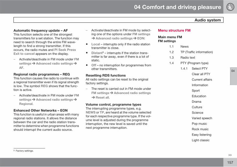
04 Comfort and driving pleasure
Audio system
04
��
157
Automatic frequency update – AF
This function selects one of the strongesttransmitters for a set station. The function mayneed to search through the entire FM wave-length to find a strong transmitter. If thisoccurs, the radio mutes and PI Seek Press
Exit to cancel appears on the display.
� Activate/deactivate in FM mode under FM
settings Advanced radio settings
AF.
Regional radio programmes – REG
This function causes the radio to continue witha regional transmitter even if its signal strengthis low. The symbol REG shows that the func-tion is active.
� Activate/deactivate in FM mode under FM
settings Advanced radio settings
Regional.
Enhanced Other Networks – EON
This function is useful in urban areas with manyregional radio stations. It allows the distancebetween the car and the radio station trans-mitter to determine when programme functionsshould interrupt the current audio source.
� Activate/deactivate in FM mode by select-ing one of the options under FM settings
Advanced radio settings EON:
• Local – interrupts only if the radio stationtransmitter is close.
• Distant5 – interrupts if the station trans-mitter is far away, even if there is a lot ofstatic.
• Off – no interruption for programmes fromother transmitters.
Resetting RDS functions
All radio settings can be reset to the originalfactory settings.
� The reset is carried out in FM mode underFM settings Advanced radio settings
Reset all.
Volume control, programme types
The interrupting programme types, e.g.NEWS or TP, are heard at the volume selectedfor each respective programme type. If the vol-ume level is adjusted during the programmeinterruption, the new level is saved until thenext programme interruption.
Menu structure FM
Main menu FM
FM settings
1.1 News
1.2 TP (Traffic information)
1.3 Radio text
1.4 PTY (Program type)
1.4.1 Select PTY
Clear all PTY
Current affairs
Information
Sport
Education
Drama
Culture
Science
Varied speech
Pop music
Rock music
Easy listening
Light classic
5 Factory settings.
04 Comfort and driving pleasure
Audio system
04
158 * Option/accessory, for more information, see Introduction.
Classical
Other music
Weather & metro
Finance
Children's programs
Social affairs
Religion
Phone in
Travel & touring
Leisure & hobby
Jazz music
Country music
National music
Oldies music
Folk music
Documentary
1.4.2 Search PTY
1.4.3 Show PTY text
1.5 Advanced radio settings
1.5.1 TP station
1.5.2 News station
1.5.3 AF
1.5.4 EON
Off
Local
Distant
1.5.5 Regional
1.5.6 Reset all FM settings
Radio system - DAB*
General
DAB (Digital Audio Broadcasting) is a digitalbroadcasting system for radio.
NOTE
This system does not support DAB+.
Service and Ensemble
• Service - Channel, radio channel (onlyaudio services are supported by the sys-tem).
• Ensemble - A collection of radio channelson the same frequency.
Storing channel groups (Ensemble learn)
When the vehicle is moved to a new broad-casting area, programming of existing channelgroups in the area can take place.
Programming of channel groups creates anupdated list of all available channel groups.The list is not updated automatically. Program-ming takes place via the Ensemble learn
menu or directly by means of a long press onAUTO. If can take up to a minute to program achannel group if both Band III and LBand areselected.
Wavelength
DAB is transmitted on two wavelengths6; Band
III and LBand.
• Band III – over the whole country7
• LBand - mainly in large cities
By selecting for example Band III on its own,channel programming takes place morequickly than if both Band III and LBand areselected. It is not certain that all channelgroups will be found. Wavelength selectiondoes not affect the stored memories.
Navigation via lists
There are three types of basic list which can beused for navigation:
6 Not all areas/countries use both wavelengths.7 During a build-up phase DAB will not cover the whole country but will only work in larger urban areas.
04 Comfort and driving pleasure
Audio system
04
��
159
• Ensemble - Shows channel groups thatthe receiver has obtained via channelgroup programming.
• Service - Shows channels irrespective ofthe channel group to which they are allo-cated. The list can also be filtered usingDAB PTY (see below).
• Subchannel - Subchannels to a selectedchannel.
The lists can be accessed via the menu. Thechannel groups can also be accessed bypressing ENTER.
Scanning
Scanning means that all channels in the list areplayed for 10 seconds each.
� Press SCAN to activate
Scanning can also be selected in DAB-PTYmode. In which case only channels of the pre-selected programme type are played.
� Stop scanning by pressing SCAN once, orby pressing EXIT.
Subchannel
Secondary components are usually namedsubchannels. These are temporary and cancontain e.g. translations of the main pro-gramme into other languages.
If one or more subchannels are broadcast thenthe > symbol is shown to the right of the chan-nel name in the display. A subchannel is indi-cated by the > symbol appearing to the left ofthe channel name in the display.
To access a subchannel:
� Press .
To navigate between subchannels:
� Press or .
Subchannels can only be accessed on theselected main channel and not on any otherone without selecting it.
DAB PTY (program type)
DAB PTY selects one type of radio pro-gramme. There are 29 different programmetypes which also include different programmecategories. After selecting a programme type,navigation only takes place within the channelsbroadcasting that type.
Exit this mode as follows:
� Press EXIT
It is also possible to select a preset channel orexit DAB PTY via the menu. In certain casesDAB radio will exit PTY mode when DAB toDAB linking (see below) is implemented.
DAB to DAB link
It is possible to exit a channel with poor or noreception to the same channel in another chan-nel group with better reception. There may bea certain delay when changing channel group.There may be a period of silence between thecurrent channel no longer being available to thenew channel becoming available.
DAB display settings
1. Basic - Only the channel name is shown ifa primary component is being played. Asubchannel name is shown if it is a sub-channel being played
2. Ensemble - Adds the channel group nameto the channel name
3. Ensemble +PTY - Adds the programmetype name under the channel name
Preset
10 station presets can be stored per wave-length. DAB has 2 memories for presets:DAB1 and DAB2. The stored presets areselected using the preset buttons.
A preset contains one channel but no sub-channels. If a subchannel is being played anda preset is saved then only the channel ID isregistered. This is because subchannels aretemporary. At the next attempt to retrieve thepreset, the channel which contained the sub-
04 Comfort and driving pleasure
Audio system
04
160
channel will be played. The preset is notdependent on the channel list.
A saved channel does not have to be in thechannel list for it to be playable. If the channelis loaded when it is not available then a presetnumber is shown and there is silence until anavailable preset is selected for loading. Alter-natively another channel.
NOTE
The audio system's DAB system does notsupport all functions available in the DABstandard.
Menu structure DAB
Main menu DAB
1. Select ensemble
2. Select service
3. Select subchannel
4. DAB PTY
4.1. DAB PTY off
4.2. News
4.3. Current affairs
4.4. Information
4.5. Sport
4.6. Education
4.7. Drama
4.8. Arts
4.9. Science
4.10. Talk
4.11. Pop music
4.12. Rock music
4.13. Calm music
4.14. Light classic
4.15. Classical music
4.16. Other music
4.17. Weather
4.18. Finance
4.19. Children
4.20. Factual
4.21. Religion
4.22. Phone in
4.23. Travel
4.24. Leisure
4.25. Jazz and blues
4.26. Country music
4.27. National music
4.28. Oldies music
4.29. Folk music
4.30. Documentary
5. Ensemble learn
6. DAB settings
6.1. DAB display settings
6.1.1. Ensemblename
6.1.2. Ensemblename andPTY
6.1.3. Basic
6.2. DAB to DAB link
6.3. FM traffic
6.4. Select DAB band
6.4.1. Band III
6.4.2. LBand
6.4.3. LBand & BandIII
6.5. Reset DAB

04 Comfort and driving pleasure
RSE - Rear Seat Entertainment system - Dual Screen*
04
��
* Option/accessory, for more information, see Introduction. 161
General
The RSE system can be used at the same timeas the car's infotainment system.
When the rear seat passengers are using DVD,RSE-AUX or watching TV1 while listening withheadphones, the driver and front seat passen-ger can still use the car's radio or CD player.
Power consumption, ignition positions
The system can be activated in ignition positionI or II and while the engine is running. When thecar is being started the film stops temporarilyand continues when the engine has started.
When the system has been used once withoutthe ignition in position I it is blocked. To restart,ignition position I must be activated.
NOTE
In the event of extended use (more than 10minutes) with the engine switched off - thecapacity of the car's battery may decreaseto such a low level that the engine cannotbe started.
In which case a message will appear on thescreen.
TV overview
Press and select TV I DVD I AUX
TV MEDIA MENU.
Channel lock list
Channel manage-
ment
Channel search Management of
new carriers
Add carrier
Information on fre-
quency
Delete a frequency
Delete all frequen-
cies
Auto scan
System settings TV
Audio mode
Factory default
Time zone setting
CI module No CAM inserted
CI module infor-
mation
Signal strength
System settings TV
Press MEDIA MENU System settings
TV.
Languages
TV menu language
E.g. English
Pict. format 16:9
4:3
Auto
1 TV is an option for the RSE system.

04 Comfort and driving pleasure
RSE - Rear Seat Entertainment system - Dual Screen*
04
162 * Option/accessory, for more information, see Introduction.
Mode (screenmode)
Standard
Zoom
Full screen
Centered
Audio mode Right
Left
Banner timeout
The menus can bedisplayed forbetween8-40 seconds.
System settings-Sound mode
Press MEDIA MENU System settings
Audio mode.
The original speech for a TV programme canbe replaced with speech in another language ifthe programme is broadcast with several audiotracks.
Audio Audio - 1, e.g. ENG.
Audio - 2, e.g. GER.
Audio mode Right
Left
Stereo
AC3
System settings-Factory settings
Press MEDIA MENU System settings
Factory default.
The system's factory settings are restoredhere.
System settings-Time zone settings
Press MEDIA MENU System settings
Time zone setting.
For local programme times to be displayedcorrectly the time zone must be set. TheGUIDE and INFO button menus and the clockare affected by local time zones.
Pay channels
To watch pay channels a payment card mustbe fitted in an adapter which is inserted into thedigital TV box.
G03
1510
The box is located under the hatch in the cargoarea
1. Open the hatch in the cargo area, the boxis protected by a cover.
2. Open the rubber cover on the box.
3. Fit the payment card into the adapter.Make sure that it is fitted correctly.
4. Insert the adapter in the digital TV box.Make sure that it is inserted correctly.> The system will detect that it has
received new information.
5. Search to find the new channels that havebecome available, see the section "Pay-ment card TV channels" below.

04 Comfort and driving pleasure
RSE - Rear Seat Entertainment system - Dual Screen*
04
��
* Option/accessory, for more information, see Introduction. 163
Payment card TV channels
Search so that the system identifies the pay-ment card's channels.
1. Press MEDIA MENU on the remote con-trol.
2. Select Channel search Auto scan.
3.Select country and press .
Formats supported by the digital TV box
The TV system supports MPEG-2 transmis-sions. There is the option to receiveMPEG-4 transmissions if you buy an adapter.This adapter is inserted into the digital TV boxand is fitted in the same way as the adapter forthe payment card. See the section "Pay chan-nels" above.
Music
Playing back a CD disc
1. Insert the CD with the label side turnedfrom the buttons.> The disc starts to play back automati-
cally.
2. Switch on the wireless headphones, selectCH A for left-hand screen or CH B for right-hand screen.
> The sound is directed to the head-phones.
3. Adjust the audio volume in the headphonesusing the volume control/wheel on theheadphones.
Alternatively - activate the car's audio sys-
tem in MODE-AUX and press A B onthe remote control to listen via the speak-ers.
Selecting within a disc directory
1. Load the disc.
2.Press .
3. Scroll using the navigation buttons toselect a file.
4.Press to select the subdirectory.
Different playback options
The disc can be played back in different ways,scroll with the navigation buttons to selectplayback option.
When the dialogue box appears:
1. Press the right-hand navigation button tomove over in the right-hand menu.
2. Scroll using the navigation buttons toselect playback options.
3.Confirm with .
Change CD track
�Change CD track with or fast-wind by holding the buttonsdepressed.
Pause
1.Pause and restart the disc with .
2.Stop the disc with .
3.Press again to eject the disc.
Discs copied privately can be used.
However, playback and quality depend on thequality of the source file, format and disc qual-ity.
AUX input, Electrical socket 12 V
The input allows you to connect other equip-ment. Always follow the instructions includedwith the external equipment, or from the man-ufacturer or reseller, when connecting. Equip-ment connected via the RSE AUX input can usethe screens, wireless headphones, head-phones sockets and the car's speakers.

04 Comfort and driving pleasure
RSE - Rear Seat Entertainment system - Dual Screen*
04
164 * Option/accessory, for more information, see Introduction.
Connecting the RSE AUX input
G03
0382
The RSE-AUX input is located under the front arm-rest.
1. Connect the video cable to the yellowsocket.
2. Connect the left-hand audio cable to thewhite socket and the right-hand one to thered socket.
3. Connect the power cable to the powersocket if your equipment is designed for12 V.
For electrical socket location, see page 204
System
Formats supported by the system.
Audioformat
CD-DA, DVD Audio Playback,MP3, WMA
Videoformat
DVD video, VCD, SVCD, DivX/MPEG-4, WMA video, Photo CDKodak, Photo CD JPG
Discformat
DVD-RAM, DVD-ROM, DVD-RW,DVD+RW, DVD-R, DVD+R, CD-R,CD-ROM, CD-RW, CD-3, HDCD
Advanced system settings
These settings can only be accessed when theDVD player is empty.
� Press MEDIA MENU.
GENERAL SETUP ANGLE MARK
CAPTION
AUDIO SETUP COMPRESSION
DVX(R)
REGISTRATION
PREFERENCES TV TYPE
AUDIO
SUBTITLE
DEFAULTS
Changing the battery in the remotecontrol and wireless headphones
The remote control and headphones are pow-ered by 2 AAA batteries.
Take along extra batteries for a long journey.
1. Unscrew the screw and detach the batterycover.
2. Remove the used batteries, turn the newbatteries in accordance with the symbolsin the battery compartment and insertthem.
3. Fit the cover and screw in the screw.

04 Comfort and driving pleasure
RSE - Rear Seat Entertainment system - Dual Screen*
04
* Option/accessory, for more information, see Introduction. 165
Wireless headphones
1. Unscrew the screw and detach the batterycover.
2. Remove the used batteries, turn the newbatteries in accordance with the symbolsin the battery compartment and insertthem.
3. Fit the cover and screw in the screw.
NOTE
If the system is too hot to be used or if bat-tery voltage is too low then an informationmessage appears on the screen.
Environmental care
Be sure to dispose of the exhausted batteriesin an environmentally safe manner.

04 Comfort and driving pleasure
Trip computer
04
166 * Option/accessory, for more information, see Introduction.
General
Information display and controls.
READ - confirms
Thumbwheel – browse between menusand options in the trip computer list
RESET – resets
The trip computer's menu is in a variable loop.One of the menu options is a blank display - italso marks the beginning/end of the loop.
Functions
NOTE
If a warning message appears when the tripcomputer is used then the message mustfirst be acknowledged before the trip com-puter can be reactivated. Acknowledge thewarning message by pressing READ.
To change unit for distance and speed - con-tact a workshop. An authorised Volvo work-shop is recommended.
Average speed
Average speed is calculated from the lastresetting. Reset using RESET.
Instantaneous
Current fuel consumption is calculated everysecond. The information on the display isupdated every couple of seconds. When thecar is stationary, "----" appears on the display.
Average
Average fuel consumption is calculated fromthe last resetting. Reset using RESET.
NOTE
There may be a slight error in the reading ifa fuel-driven supplementary and/or parkingheater* has been used.
Km to empty tank
The calculation is based on the average fuelconsumption over the last 30 km and theremaining driveable fuel quantity. The displayshows the approximate distance that can bedriven with the fuel quantity remaining in thetank.
An economic driving style generally results in alonger driving distance. For more informationon how you can influence fuel consumption,see page 11.
No guaranteed range remains when the displayshows "---- km to empty tank". Refuel assoon as possible.
NOTE
There may be a slight error in the reading ifthe driving style has been changed.
Resetting
1. Select --- km/h average speed or --.- l/100km average.
04 Comfort and driving pleasure
Trip computer
04
* Option/accessory, for more information, see Introduction. 167
2. Press and hold RESET forapprox. 1 second to reset the selectedfunction. If RESET is kept depressed for atleast 3 three seconds then Average speedand Average are reset simultaneously.
Current speed*1
The instrument panel display shows currentspeed in mph if the speedometer is graduatedin km/h. If the speedometer is graduated inmph then the current speed is shown in km/h.
1 Only certain markets.
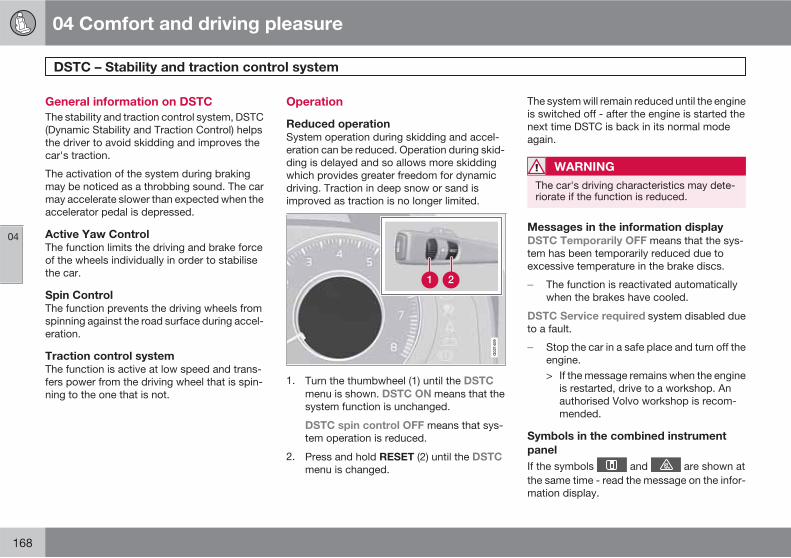
04 Comfort and driving pleasure
DSTC – Stability and traction control system
04
168
General information on DSTC
The stability and traction control system, DSTC(Dynamic Stability and Traction Control) helpsthe driver to avoid skidding and improves thecar's traction.
The activation of the system during brakingmay be noticed as a throbbing sound. The carmay accelerate slower than expected when theaccelerator pedal is depressed.
Active Yaw Control
The function limits the driving and brake forceof the wheels individually in order to stabilisethe car.
Spin Control
The function prevents the driving wheels fromspinning against the road surface during accel-eration.
Traction control system
The function is active at low speed and trans-fers power from the driving wheel that is spin-ning to the one that is not.
Operation
Reduced operation
System operation during skidding and accel-eration can be reduced. Operation during skid-ding is delayed and so allows more skiddingwhich provides greater freedom for dynamicdriving. Traction in deep snow or sand isimproved as traction is no longer limited.
G02
1409
1. Turn the thumbwheel (1) until the DSTC
menu is shown. DSTC ON means that thesystem function is unchanged.
DSTC spin control OFF means that sys-tem operation is reduced.
2. Press and hold RESET (2) until the DSTC
menu is changed.
The system will remain reduced until the engineis switched off - after the engine is started thenext time DSTC is back in its normal modeagain.
WARNING
The car's driving characteristics may dete-riorate if the function is reduced.
Messages in the information display
DSTC Temporarily OFF means that the sys-tem has been temporarily reduced due toexcessive temperature in the brake discs.
� The function is reactivated automaticallywhen the brakes have cooled.
DSTC Service required system disabled dueto a fault.
� Stop the car in a safe place and turn off theengine.> If the message remains when the engine
is restarted, drive to a workshop. Anauthorised Volvo workshop is recom-mended.
Symbols in the combined instrument
panel
If the symbols and are shown atthe same time - read the message on the infor-mation display.

04 Comfort and driving pleasure
DSTC – Stability and traction control system
04
169
If the symbol appears alone then it mayappear as follows:
• Flashing light means that the system isnow being activated.
• Constant glow for 2 seconds means sys-tem check when the engine is started.
• Constant glow after starting the engine orwhile driving means system fault.

04 Comfort and driving pleasure
Adapting driving characteristics
04
170 * Option/accessory, for more information, see Introduction.
Active chassis (Four-C)*
Active chassis, Four-C (Continously ControlledChassis Concept), regulates the characteris-tics of the shock absorbers so that the car'sdriving characteristics can be adjusted. Thereare three settings: Comfort, Sport andAdvanced.
Comfort
This setting means that the car is perceived asbeing more comfortable on rough and unevenroad surfaces. Shock absorption is soft and themovement of the body is smooth and gentle.
Sport
This setting means that the car is perceived asbeing more sporty and is recommended formore active driving. Steering response is fasterthan in the Comfort mode. Shock absorption isharder and the body follows the road in orderto reduce rolling during cornering.
Advanced
This setting is only recommended on very evenand smooth road surfaces.
The shock absorbers are optimised for maxi-mum roadholding and rolling in bends is furtherminimised.
Operation
Chassis settings.
Use the buttons in the centre console tochange setting. The setting in use when theengine is switched off is activated next time theengine is started.
Speed related power steering*
Steering force increases with the speed of thecar to give the driver enhanced sensitivity. Thesteering is firmer and more immediate onmotorways. Steering is light and requires noextra effort when parking and at low speed.
The driver can choose between three differentlevels of steering force for road responsivenessor steering sensitivity. Go to Car settings
Steering force level in the menu system andselect Low, Medium or High.
For a description of the menu system, seepage 131. This menu cannot be accessedwhile the car is in motion.

04 Comfort and driving pleasure
Cruise control*
04
��
* Option/accessory, for more information, see Introduction. 171
Operation
G02
1411
Steering wheel keypad and display.
Cruise control - On/Off.
Standby mode ceases and the storedspeed is resumed.
Standby mode
Activate and adjust the speed.
Selected speed (in brackets = Standbymode)
Activating and setting the speed
Switch on the cruise control with one press onthe steering wheel button CRUISE - the sym-bol is illuminated in the display (5) and thebrackets around (---) km/h show that thecruise control is set in standby mode.
The cruise control is then activated with or, after which the current speed is stored in
the memory - the display text (---) km/h
changes to show the selected speed, e.g. 100
km/h.
NOTE
Cruise control cannot be engaged atspeeds below 30 km/h.
Changing the speed
In active mode the speed is adjusted with longor short presses on or - the last press isstored in the memory.
A temporary increase in speed with the accel-erator pedal, e.g. during overtaking, does notaffect the cruise control setting - the car returnsto the set speed when the accelerator pedal isreleased.
NOTE
If any cruise control button is helddepressed for more than approx. 1 minutethen cruise control is disengaged. Theengine must be switched off in order to resetcruise control.
Temporary deactivation - standby mode
Press to temporarily disengage the cruisecontrol and set it in standby mode - set speedis shown in brackets in the display (5), e.g.(100) km/h.
Automatic standby mode
Cruise control is temporarily disengaged andset in standby mode if:
• wheels lose traction
• the foot brake is used
• speed falls below approx. 30 km/h
• the clutch pedal is depressed
• the gear selector is moved to neutral posi-tion (automatic gearbox)
• the driver maintains a speed higher thanthe set speed for longer than 1 minute.
The driver must then regulate the speed.
Resume set speed
Cruise control in standby mode is re-activatedwith one press on the steering wheel button
- the speed is then set to the last storedspeed.
NOTE
A significant increase in speed may ariseafter the speed has been resumed with .
04 Comfort and driving pleasure
Cruise control*
04
172 * Option/accessory, for more information, see Introduction.
Deactivate
The cruise control is switched off with thesteering wheel button CRUISE or by switchingoff the engine - the set speed is deleted fromthe memory and cannot be resumed with the
button.

04 Comfort and driving pleasure
Adaptive cruise control*
04
��
* Option/accessory, for more information, see Introduction. 173
General information on ACC
The adaptive cruise control ACC – AdaptiveCruise Control) helps the driver maintain a safedistance from the vehicle ahead. It provides amore relaxing driving experience on long jour-neys on motorways and long straight mainroads in smooth traffic flows.
The driver sets the desired speed and timeinterval to the car in front. When the radardetector detects a slower vehicle in front of thecar, the speed is automatically adapted to that.When the road is clear again the car returns tothe selected speed.
If the adaptive cruise control is switched off orset to the standby mode and the car comes tooclose to a vehicle in front, then the driver iswarned by Distance Alert (see page 181) aboutthe short distance.
WARNING
The driver must always be observant withregard to the traffic conditions and intervenewhen the adaptive cruise control is notmaintaining a suitable speed or suitable dis-tance.
The adaptive cruise control cannot handleall traffic, weather and road conditions.
The Function section and onwards informsabout limitations of which the driver shouldbe aware before using the adaptive cruisecontrol.
The driver always bears responsibility formaintaining the correct distance and speed,even when the adaptive cruise control isbeing used.
IMPORTANT
Maintenance of adaptive cruise controlcomponents must only be performed at aworkshop - an authorised Volvo workshopis recommended.
Function
G02
1412
Functions overview.
Warning lamp, braking by driver required
Steering wheel keypad
Radar sensor
Adaptive cruise control consists of a cruisecontrol system and a coordinated spacing sys-tem.

04 Comfort and driving pleasure
Adaptive cruise control*
04
174 * Option/accessory, for more information, see Introduction.
WARNING
Adaptive cruise control is not a collisionavoidance system. The driver must inter-vene if the system does not detect a vehiclein front.
The adaptive cruise control does not brakefor humans or animals, and not for smallvehicles such as bicycles and motorcycles.Nor for oncoming, slow or stationary vehi-cles and objects.
Do not use the adaptive cruise control, forexample, in city traffic, in dense traffic, atjunctions, on slippery surfaces, with a lot ofwater or slush on the road, in heavy rain/snow, in poor visibility, on winding roads oron slip roads.
The distance to the vehicle ahead is mainlymeasured by a radar sensor. Cruise controlregulates the speed with acceleration andbraking. It is normal for the brakes to emit a lowsound when they are being used by cruise con-trol.
WARNING
The brake pedal moves when the cruisecontrol brakes. Do not rest your foot underthe brake pedal as it could become trapped.
The adaptive cruise control aims to follow thevehicle ahead in the same lane at a time interval
set by the driver. If the radar sensor cannot seeany vehicle in front then the car will insteadmaintain the cruise control's set speed. Thisalso happens if the speed of the vehicle in frontexceeds the cruise control's set speed.
The cruise control aims to control the speed ina smooth way. In situations that require rapidbraking the driver must brake himself/herself.This applies with large differences in speed, orif the vehicle in front brakes heavily. Due to lim-itations in the radar sensor, braking may comeunexpectedly or not at all, see page 177.
The adaptive cruise control can be activated tofollow another vehicle at speeds from30 km/h up to 200 km/h. If the speed fallsbelow 30 km/h or if the engine speed becomestoo low, the cruise control is set in standbymode at which automatic braking ceases - thedriver must then take over himself/herself tomaintain a safe distance to the vehicle ahead.
Warning lamp - braking by driver
required
Adaptive cruise control has a braking capacitythat is equivalent to approximately 25% of thecar's braking capacity.
If the car needs to be braked more heavily thancruise control capacity and the driver does notbrake, then the cruise control uses the collisionwarning system's warning lamp and warning
sound (see page 184) to alert the driver thatimmediate intervention is required.
NOTE
The warning lamp may be difficult to noticein strong sunlight or when sunglasses arebeing worn.
WARNING
Cruise control only warns of vehiclesdetected by the radar sensor. Consequentlythere may be no warning or it may be sub-ject to a delay. Do not wait for a warning butbrake when it is necessary.
Steep roads and/or heavy load
Bear in mind that the adaptive cruise control isprimarily intended for use when driving on levelroad surfaces. The cruise control may have dif-ficultly in keeping the correct distance from thevehicle ahead when driving on steep roads,with a heavy load or with a trailer - in whichcase, be extra attentive and ready to slowdown.

04 Comfort and driving pleasure
Adaptive cruise control*
04
��
* Option/accessory, for more information, see Introduction. 175
Operation
Steering wheel keypad and display.
Standby mode ceases and the storedspeed is resumed.
Cruise control - On/Off or Standby mode.
Time interval - Increase/decrease.
Activate and adjust the speed.
Selected speed (in brackets = Standbymode)
Time interval - On, during adjustment.
Time interval - On, after adjustment.
Activating and setting the speed
Switch on cruise control with one press on thesteering wheel button - the symbol isilluminated in the display. The brackets (6) at
(---) mean that cruise control is set in standbymode.
The cruise control is then activated with or, after which the current speed is stored in
the memory - the display text (---) changes toshow the selected speed, e.g. 100 withoutbrackets.
When the symbol changesto the radar sensor hasdetected a vehicle.
Only when the symbol (with car) is illuminated, is thedistance to the vehicle in front
regulated by the cruise control.
NOTE
Cruise control cannot be engaged atspeeds below 30 km/h.
Changing the speed
In active mode the speed is adjusted with longor short presses on , or . In activemode the button has the same function as
but results in a lower increase in speed. Thelast press is stored in the memory.
NOTE
If any cruise control button is helddepressed for more than approx. 1 minutethen cruise control is disengaged. Theengine must be switched off in order to resetcruise control.
In certain situations, cruise control cannotbe activated. Then the display showsCruise control Unavailable, seepage 179.
Set time interval
Different time intervals to thevehicle in front can beselected and shown in thedisplay as 1-5 horizontal lines- the more lines the longer thetime distance. One line corre-sponds to approximately
1 second, 5 lines approximately 2.5 seconds.
The time interval is increased using the steeringwheel button and decreased using .
At low speed, when the distances are short, theadaptive cruise control increases the timeinterval slightly.
The adaptive cruise control allows the timeinterval to vary noticeably in certain situationsin order to allow the car to follow the vehicle infront smoothly and comfortably.

04 Comfort and driving pleasure
Adaptive cruise control*
04
176 * Option/accessory, for more information, see Introduction.
Note that a short time interval gives the drivera short time to react and act if something unex-pected happens in the traffic.
The number of lines for theselected time interval isshown during the setting itselfand for several seconds after-wards. Then a smaller scaleversion of the symbol isshown to the right of the dis-
play. The same symbol is also shown whenDistance Alert is activated, see page 181.
NOTE
Only use the time interval that is allowed inaccordance with local traffic regulations.
If cruise control does not seem to react toactivation the reason may be that the timeinterval to the closest vehicle prevents anincrease in speed.
The higher the speed, the longer the calcu-lated distance in metres for a specific timeinterval.
Temporary deactivation - standby mode
Press the steering wheel button to tempo-rarily disengage the cruise control and set it instandby mode - set speed is shown in bracketsin the display, e.g. (100).
Standby mode due to driver intervention
Cruise control is temporarily disengaged andset in standby mode if:
• the foot brake is used
• the clutch pedal is depressed for longerthan 1 minute1
• the gear selector is moved to neutral posi-tion (automatic gearbox)
• the driver maintains a speed higher thanthe set speed for longer than 1 minute
The driver must then regulate the speed.
A temporary increase in speed with the accel-erator pedal, e.g. during overtaking, does notaffect the cruise control setting - the car returnsto the last stored speed when the acceleratorpedal is released.
Automatic standby mode
The adaptive cruise control is dependent onother systems, such as Stability and tractioncontrol (DSTC). If any of these systems stopworking then cruise control is automaticallydeactivated.
In the event of automatic deactivation a signalwill sound and the message Cruise control
Cancelled is shown in the display. The drivermust then intervene and adapt the speed anddistance to the vehicle ahead.
An automatic deactivation can be due to:
• engine speed is too low/high
• speed falls below 30 km/h
• wheels lose traction
• brake temperature is high
• the radar sensor is covered e.g. by wetsnow or heavy rain (radar waves blocked).
Resume set speed
Cruise control in standby mode is re-activatedwith one press on the steering wheel button
- the speed is then set to the last storedspeed.
NOTE
A significant increase in speed may ariseafter the speed has been resumed with .
Deactivate
The cruise control is switched off with thesteering wheel button in standby mode orwith one long press in active mode. The setspeed is cleared and cannot be resumed withthe button.
1 Disengaging and selecting a higher or lower gear does not involve standby mode.

04 Comfort and driving pleasure
Adaptive cruise control*
04
��
* Option/accessory, for more information, see Introduction. 177
The radar sensor and its limitations
Apart from the adaptive cruise control, theradar sensor is also used by the CollisionWarning with Auto Brake function (seepage 184) and the Distance Alert function (seepage 181). The function of the radar sensor isto detect cars or larger vehicles in the samedirection, in the same lane.
Modification of the radar sensor could result init being illegal to use.
WARNING
The driver must always be observant withregard to the traffic conditions and intervenewhen the adaptive cruise control is notmaintaining a suitable speed or suitable dis-tance.
The adaptive cruise control cannot handleall traffic, weather and road conditions.
The Function section and onwards informsabout limitations of which the driver shouldbe aware before using the adaptive cruisecontrol.
The driver always bears responsibility formaintaining the correct distance and speed,even when the adaptive cruise control isbeing used.
WARNING
Accessories or other objects such as auxil-iary lamps must not be installed in front ofthe grille.
WARNING
Adaptive cruise control is not a collisionavoidance system. The driver must inter-vene if the system does not detect a vehiclein front.
The adaptive cruise control does not brakefor humans or animals, and not for smallvehicles such as bicycles and motorcycles.Nor for oncoming, slow or stationary vehi-cles and objects.
Do not use the adaptive cruise control, forexample, in city traffic, in dense traffic, atjunctions, on slippery surfaces, with a lot ofwater or slush on the road, in heavy rain/snow, in poor visibility, on winding roads oron slip roads.
The capacity of the radar sensor to detect vehi-cles in front is reduced significantly:
• if the radar sensor becomes blocked andcannot detect other vehicles e.g. in heavyrain or slush, or if other objects have col-lected in front of the radar sensor.
NOTE
Keep the surface in front of the radar sensorclean.
• if the speed of vehicles in front is signifi-cantly different from your own speed.
Examples where the cruise control does
not work optimally
The radar sensor has a limited field of vision. Insome situations another vehicle is notdetected, or the detection is made later thanexpected.

04 Comfort and driving pleasure
Adaptive cruise control*
04
178 * Option/accessory, for more information, see Introduction.
G02
1414
The ACC cannot see small vehicles (Dark triangle:ACC field of vision).
Sometimes the radar sensor cannot detectvehicles at close distances, e.g. a vehiclethat drives in between the car and vehiclesin front.
Small vehicles, such as motorcycles, orvehicles not driving in the centre of the lanecan remain undetected.
In bends the radar sensor may detect thewrong vehicle or lose a detected vehiclefrom view.
Fault tracing and action
If the display shows the message Radar
blocked See manual this means that theradar signals from the radar sensor are blockedand that vehicles in front of the car could notbe detected.
In turn this means that the Adaptive CruiseControl, Distance Alert and Collision Warningwith Auto Brake functions are not operatingeither.
The following table presents possible causesfor a message being shown along with theappropriate action.
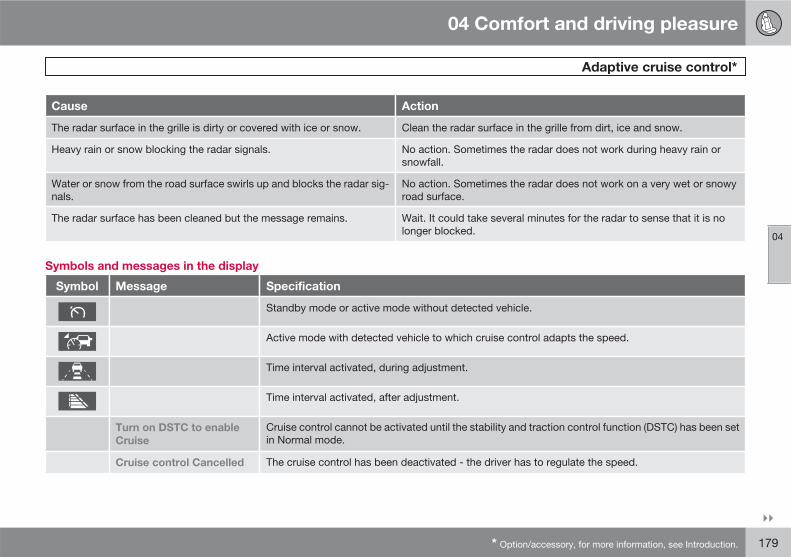
04 Comfort and driving pleasure
Adaptive cruise control*
04
��
* Option/accessory, for more information, see Introduction. 179
Cause Action
The radar surface in the grille is dirty or covered with ice or snow. Clean the radar surface in the grille from dirt, ice and snow.
Heavy rain or snow blocking the radar signals. No action. Sometimes the radar does not work during heavy rain orsnowfall.
Water or snow from the road surface swirls up and blocks the radar sig-nals.
No action. Sometimes the radar does not work on a very wet or snowyroad surface.
The radar surface has been cleaned but the message remains. Wait. It could take several minutes for the radar to sense that it is nolonger blocked.
Symbols and messages in the display
Symbol Message Specification
Standby mode or active mode without detected vehicle.
Active mode with detected vehicle to which cruise control adapts the speed.
Time interval activated, during adjustment.
Time interval activated, after adjustment.
Turn on DSTC to enable
Cruise
Cruise control cannot be activated until the stability and traction control function (DSTC) has been setin Normal mode.
Cruise control Cancelled The cruise control has been deactivated - the driver has to regulate the speed.

04 Comfort and driving pleasure
Adaptive cruise control*
04
180 * Option/accessory, for more information, see Introduction.
Symbol Message Specification
Cruise control Unavailable Cruise control cannot be activated.
This could be due to:
• brake temperature is high
• the radar sensor is blocked by e.g. wet snow or rain.
Radar blocked See manual Cruise control temporarily disengaged.
• The radar sensor is blocked and cannot detect other vehicles. For example, in the event that heavyrain or if slush has collected in front of the radar sensor.
Read about the limitations of the radar sensor, see page 177.
Cruise control Service
required
Cruise control not working.
• Contact a workshop - an authorised Volvo workshop is recommended.

04 Comfort and driving pleasure
Distance Alert*
04
��
* Option/accessory, for more information, see Introduction. 181
General
Distance Alert is a function that informs thedriver about the time interval to vehicles infront.
Distance alert is active at speeds above30 km/h and only reacts to vehicles driving infront of the car, in the same direction. No dis-tance information is provided for oncoming,slow or stationary vehicles.
G017362
A small section of the red warning lamp in thewindscreen illuminates with a constant glow ifthe distance to the vehicle in front is shorterthan the set time interval.
NOTE
Distance Alert is deactivated during the timethat Adaptive Cruise Control is active.
WARNING
Distance Alert only reacts if the distance tothe vehicle ahead is shorter than the presetvalue - the speed of the driver's vehicle isnot affected.
Operation
Press the button in the centre console to switchthe function on or off. The function is switchedon if one lamp is illuminated in the button.
Set time interval
Controls and display.
Time interval - Increase/decrease
Time interval - On, during adjustment
Time interval - On, after adjustment
Time intervals are increased using anddecreased using .
Different time intervals to thevehicle in front can beselected and shown in thedisplay as 1-5 horizontal lines- the more lines the longer thetime distance. One line corre-sponds to approximately
1 second to the vehicle in front, 5 lines approx-imately 2.5 seconds.

04 Comfort and driving pleasure
Distance Alert*
04
182 * Option/accessory, for more information, see Introduction.
The number of lines for theselected time interval isshown during the setting itselfand for several seconds after-wards. Then a smaller scaleversion of the symbol isshown to the right of the dis-
play. The same symbol is also shown whenadaptive cruise control is activated.
NOTE
The higher the speed, the longer the calcu-lated distance in metres for a specific timeinterval.
The set time interval is also used by theadaptive cruise control function, seepage 175.
Only use the time interval that is allowed inaccordance with local traffic regulations.
Limitations
The function uses the same radar sensor asadaptive cruise control and the collision warn-ing system. For more information on the radarsensor and its limitations, see page 177.
NOTE
Strong sunlight, reflections or strong varia-tions in light intensity, as well as wearingsunglasses, could mean that the warninglight in the windscreen cannot be seen.
Poor weather or winding roads could affectthe radar sensor's capacity to detect vehi-cles in front.
The size of other vehicles could also affectdetection capacity, e.g. motorcycles. Thiscould mean that the warning lamp illumi-nates at a shorter distance than the settingor that the warning is temporarily absent.
Extremely high speeds can also cause thelamp to illuminate at a shorter distance thanthat set due to limitations in sensor range.
Symbols and messages in the display
Symbol Message Specification
Set time interval, during adjustment.
Set time interval, after adjustment.

04 Comfort and driving pleasure
Distance Alert*
04
* Option/accessory, for more information, see Introduction. 183
Symbol Message Specification
Radar blocked.
See manual
Distance Alert temporarily disengaged.
The radar sensor is blocked and cannot detect other vehicles, e.g. in the event that heavy rain or slushhas collected in front of the radar sensor.
Read about the limitations of the radar sensor, see page 177.
Collision warn. Service
required
Distance Alert and Collision Warning with Auto Brake are fully or partially disengaged.
Visit a workshop if the message remains - an authorised Volvo workshop is recommended.

04 Comfort and driving pleasure
Collision Warning with Auto Brake*
04
184 * Option/accessory, for more information, see Introduction.
General
Collision Warning with Auto Brake (CollisionWarning with Auto Brake) is designed to assistthe driver when there is a risk of colliding witha vehicle in front that is stationary or driving inthe same direction.
The collision warning system has the followingthree functions.
• Collision Warning – Warns the driver of apotentially imminent collision.
• Brake Support – Assists the driver tobrake effectively in a critical situation.
• Auto Brake – Brakes the car automaticallywhen a collision is unavoidable. The AutoBrake function cannot prevent a collisionbut instead aims to reduce collision speed.
The collision warning system is activated in sit-uations where the driver should have startedbraking a lot earlier, which is why the functioncannot help the driver in every situation.
Collision Warning with Auto Brake is designedto be activated as late as possible in order toavoid unnecessary intervention.
The collision warning system must not be usedas an excuse for the driver to change his/herdriving style. If the driver solely relies on Colli-sion Warning with Auto Brake to do the brak-ing, there will be a collision sooner or later.
IMPORTANT
Maintenance of collision warning systemcomponents must only be performed at aworkshop - an authorised Volvo workshopis recommended.
WARNING
The collision warning system does not workin all driving situations and traffic, weatherand road conditions. The collision warningsystem does not react to vehicles driving inanother direction to the car or to people andanimals.
Warning only activated in the event of a highrisk for collision. The Function section andthe section after advise about limitations ofwhich the driver should be aware beforeusing Collision Warning with Auto Brake.
The Auto Brake function can only reduce thecollision speed. The driver must depress thebrake pedal to achieve full brake function.
Never wait for a collision warning. Whendriving you are responsible for maintainingthe correct distance and speed, even whenthe collision warning system is used.
Function
G017382
Functions overview.
Visual warning signal in the event of a col-lision risk
Radar sensor
Camera sensor
Collision warning
Together with a camera sensor, the radar sen-sor detects stationary vehicles as well as vehi-cles driving in the same direction in front of thecar.
In the event of there being a risk of collision withsuch a vehicle your attention is drawn with ared flashing warning lamp and a warningsound.

04 Comfort and driving pleasure
Collision Warning with Auto Brake*
04
��
* Option/accessory, for more information, see Introduction. 185
Brake support
If the risk of collision still increases after thecollision warning then the brake support is acti-vated. The brake support prepares the brakesystem for rapid braking and the brakes areapplied gently, which may be noticed as aslight jerk.
If the brake pedal is depressed sufficientlyquickly then full brake function is implemented,even with light pedal force.
Auto Brake
If the driver has not yet started an evasivemanoeuvre in this situation and the risk of acollision is imminent then the Auto Brake func-tion comes into effect, without the driver need-ing to touch the brake pedal. Braking thentakes place with limited brake force in order toreduce collision speed. The driver has to brakein order to achieve full brake force.
Operation
Settings are made from the centre console dis-play via a menu system. For information onhow the menu system is used, see page 130.
NOTE
The Brake Support and Auto Brake func-tions are always enabled - they cannot bedeactivated.
On and Off
To select whether the collision warning systemshould be switched on or off: In the menu Car
settings Collision warning settings
choose between the options On or Off.
When starting the engine, the setting that wasselected when the engine was switched off isobtained automatically.
Activating/deactivating warning signals
The warning lamp is activated automaticallywhen the engine is started if the system isswitched on.
The warning sound can be activated/deacti-vated separately using the options for On orOff in the menu system under Car settings
Collision warning settings Warning
sound.
Set warning distance
The warning distance regulates the distance atwhich the visual and acoustic warnings aredeployed. Select one of the options fromLong, Normal or Short in the menu system
under Car settings Collision warning
settings Warning distance.
The warning distance determines the system'ssensitivity. Warning distance Long provides anearlier warning. First test with Long and if thissetting produces too many warnings, whichcould be perceived as irritating in certain sit-uations, then change to warning distanceNormal.
Only use warning distance Short in excep-tional cases, e.g. for dynamic driving.
NOTE
When the adaptive cruise control is in usethe warning lamp and warning sound will beused by the cruise control even if the colli-sion warning system is switched off.
The collision warning system warns thedriver in the event of a risk of a collision, butthe function cannot shorten driver reactiontime.
In order for the collision warning system tobe effective, always drive with the DistanceAlert set at time interval 4 – 5. seepage 181.

04 Comfort and driving pleasure
Collision Warning with Auto Brake*
04
186 * Option/accessory, for more information, see Introduction.
NOTE
Even if the warning distance has been set toLong then in certain situations warningscould be perceived as being late. E.g. in theevent of large differences in speed or if vehi-cles in front brake heavily.
Checking settings
The settings required can be controlled on thecentre console display. Access via the menufor Car settings Collision warning
settings, see page 131.
Limitations
The collision warning system is active from andincluding approx. 7 km/h.
The visual warning signal may be difficult tonotice in the event of strong sunlight, reflec-tions, when sunglasses are being worn or if thedriver is not looking straight ahead. The warn-ing sound should therefore always be acti-vated.
On slippery road surfaces the braking distanceis extended, which may reduce the capacity toavoid a collision. In such situations the ABSand DSTC systems will provide best possiblebraking force with maintained stability.
NOTE
The visual warning signal can be temporarilydisengaged in the event of high passengercompartment temperature caused bystrong sunlight for example. If this occursthen the warning sound is activated even ifit is deactivated in the menu system.
• Warnings may not appear if the dis-tance to the vehicle in front is small or ifsteering wheel and pedal movementsare large, e.g. a very active driving style.
WARNING
Warnings and brake interventions could beimplemented late or not at all if the trafficsituation or external influences mean thatthe radar or camera sensor cannot detect avehicle in front correctly.
The sensor system has a limited range forstationary or slow vehicles so the systemprovides less effective warnings or no warn-ings at all at a higher vehicle speed (above70 km/h) for such vehicles.
Warnings for stationary or slow-movingvehicles could be disengaged due to dark-ness.
The collision warning system uses the sameradar sensors as adaptive cruise control. For
more information on the radar sensor and itslimitations, see page 177.
An absent or late warning could mean thatthere is no brake support or it comes late.
If warnings are perceived as being too frequentor disturbing then the warning distance can bereduced. This would lead to the system warn-ing at a later stage, which reduces the totalnumber of warnings.
When the car is reversing Collision Warningwith Auto Brake cannot be activated.
Collision Warning with Auto Brake is not acti-vated at low speeds - under 4 km/h, which iswhy the system does not intervene in situationswhere the car is approaching a vehicle in frontvery slowly, e.g. when parking.
Driver commands are always prioritised, whichis why Collision Warning with Auto Brake doesnot intervene in situations where the driver issteering, braking or accelerating in a clearmanner, even if a collision is unavoidable.
When Auto Brake has prevented a collisionwith a stationary object the car remains sta-tionary for a maximum of 1.5 seconds. If the caris braked for a vehicle in front that is moving,then speed is reduced to the same speed asthat maintained by the vehicle in front.
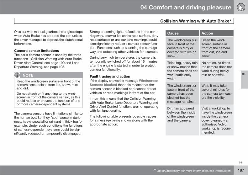
04 Comfort and driving pleasure
Collision Warning with Auto Brake*
04
��
* Option/accessory, for more information, see Introduction. 187
On a car with manual gearbox the engine stopswhen Auto Brake has stopped the car, unlessthe driver manages to depress the clutch pedalbeforehand.
Camera sensor limitations
The car's camera sensor is used by the threefunctions - Collision Warning with Auto Brake,Driver Alert Control, see page 190 and LaneDeparture Warning, see page 193.
NOTE
Keep the windscreen surface in front of thecamera sensor clean from ice, snow, mistand dirt.
Do not attach or fit anything to the wind-screen in front of the camera sensor, as thiscould reduce or prevent the function of oneor more camera-dependent systems.
The camera sensors have limitations similar tothe human eye, i.e. they "see" worse in dark-ness, heavy snowfall or rain and in thick fog forexample. Under such conditions the functionsof camera-dependent systems could be sig-nificantly reduced or temporarily disengaged.
Strong oncoming light, reflections in the car-riageway, snow or ice on the road surface, dirtyroad surfaces or unclear lane markings couldalso significantly reduce a camera sensor func-tion. Functions such as scanning the carriage-way and detecting other vehicles for example.
During very high temperatures the camera istemporarily switched off for about 15 minutesafter the engine is started in order to protectcamera functionality.
Fault tracing and action
If the display shows the message Windscreen
Sensors blocked then this means that thecamera sensor is blocked and cannot detectvehicles or road markings in front of the car.
In turn this means that the Collision Warningwith Auto Brake, Lane Departure Warning andDriver Alert Control functions are not operatingwith full functionality.
The following table presents possible causesfor a message being shown along with theappropriate action.
Cause Action
The windscreen sur-face in front of thecamera is dirty orcovered with ice orsnow.
Clean the wind-screen surface infront of the camerafrom dirt, ice andsnow.
Thick fog, heavy rainor snow means thatthe camera does notwork sufficientlywell.
No action. At timesthe camera does notwork during heavyrain or snowfall.
The windscreen sur-face in front of thecamera has beencleaned but themessage remains.
Wait. It may takeseveral minutes forthe camera to meas-ure the visibility.
Dirt has appearedbetween the insideof the windscreenand the camera.
Visit a workshop tohave the windscreeninside the cameracover cleaned - anauthorised Volvoworkshop is recom-mended.
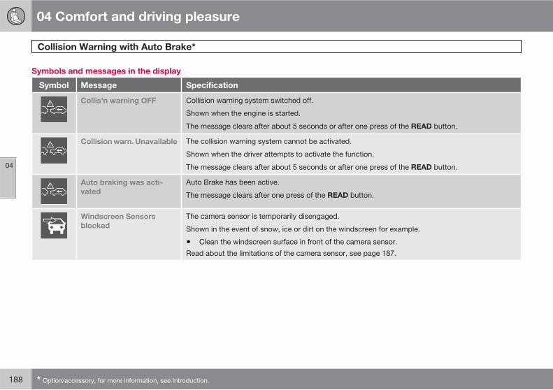
04 Comfort and driving pleasure
Collision Warning with Auto Brake*
04
188 * Option/accessory, for more information, see Introduction.
Symbols and messages in the display
Symbol Message Specification
Collis'n warning OFF Collision warning system switched off.
Shown when the engine is started.
The message clears after about 5 seconds or after one press of the READ button.
Collision warn. Unavailable The collision warning system cannot be activated.
Shown when the driver attempts to activate the function.
The message clears after about 5 seconds or after one press of the READ button.
Auto braking was acti-
vated
Auto Brake has been active.
The message clears after one press of the READ button.
Windscreen Sensors
blocked
The camera sensor is temporarily disengaged.
Shown in the event of snow, ice or dirt on the windscreen for example.
• Clean the windscreen surface in front of the camera sensor.
Read about the limitations of the camera sensor, see page 187.
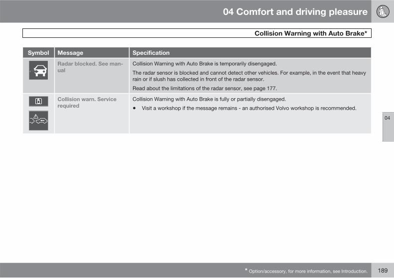
04 Comfort and driving pleasure
Collision Warning with Auto Brake*
04
* Option/accessory, for more information, see Introduction. 189
Symbol Message Specification
Radar blocked. See man-
ual
Collision Warning with Auto Brake is temporarily disengaged.
The radar sensor is blocked and cannot detect other vehicles. For example, in the event that heavyrain or if slush has collected in front of the radar sensor.
Read about the limitations of the radar sensor, see page 177.
Collision warn. Service
required
Collision Warning with Auto Brake is fully or partially disengaged.
• Visit a workshop if the message remains - an authorised Volvo workshop is recommended.
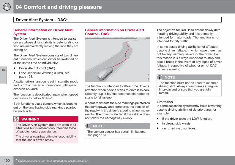
04 Comfort and driving pleasure
Driver Alert System – DAC*
04
190 * Option/accessory, for more information, see Introduction.
General information on Driver AlertSystem
The Driver Alert System is intended to assistdrivers whose driving ability is deteriorating orwho are inadvertently leaving the lane they aredriving on.
The Driver Alert System consists of two differ-ent functions, which can either be switched onat the same time or individually:
• Driver Alert Control (DAC)
• Lane Departure Warning (LDW), seepage 193.
A switched-on function is set in standby modeand is not activated automatically until speedexceeds 65 km/h.
The function is deactivated again when speeddecreases to below 60 km/h.
Both functions use a camera which is depend-ent on the lane having side markings paintedon each side.
WARNING
The Driver Alert System does not work in allsituations but is instead only intended to beof supplementary assistance.
The driver always has ultimate responsibilitythat the car is driven safely.
General information on Driver AlertControl - DAC
The function is intended to attract the driver'sattention when he/she starts to drive less con-sistently, e.g. if he/she becomes distracted orstarts to fall asleep.
A camera detects the side markings painted onthe carriageway and compares the section ofthe road with the driver's steering wheel move-ments. The driver is alerted if the vehicle doesnot follow the carriageway evenly.
NOTE
The camera sensor has certain limitations,see page 187.
The objective for DAC is to detect slowly dete-riorating driving ability and it is primarilyintended for major roads. The function is notintended for city traffic.
In some cases driving ability is not affecteddespite driver fatigue. In which case there maynot be any warning issued for the driver. Forthis reason it is always important to stop andtake a break in the event of any signs of driverfatigue, irrespective of whether or not DACissues a warning.
NOTE
The function must not be used to extend adriving stint. Always plan breaks at regularintervals and ensure that you are fullyrested.
Limitation
In some cases the system may issue a warningdespite driving ability not deteriorating, forexample:
• if the driver tests the LDW function.
• in strong side winds.
• on rutted road surfaces.

04 Comfort and driving pleasure
Driver Alert System – DAC*
04
��
* Option/accessory, for more information, see Introduction. 191
Operation
Some settings are made from the centre con-sole display and its menu system. For informa-tion on how the menu system is used, seepage 130.
The current status can be checked on the tripcomputer display with the left-hand stalkswitch.
Thumbwheel. Turn until the display showsDriver
Alert. The second row displays the Off, Unavailable or Level mark options.
READ confirms or clears a warning in thememory.
Activating Driver Alert Control
Using the centre console display with its menusystem, search and locate Car settings
Driver Alert. Select the On option.
The function is activated when speedexceeds 65 km/h and remains activeas long as the speed is over60 km/h.
The display shows a level mark with 1-5 bars,where a low number of bars indicates incon-sistent driving style. A high number of barsindicates stable driving.
If the vehicle is driven inconsistently then thedriver is alerted by an acoustic signal as well asthe text message Driver Alert Time for a
break. The warning is repeated after a time ifdriving ability does not improve.
WARNING
An alarm should be taken very seriously, asa sleepy driver is often not aware of his/herown condition.
In the event of an alarm or a feeling of tired-ness; stop the car in a safe manner as soonas possible and rest.
Studies have shown that it is equally as dan-gerous to drive while tired as it is under theinfluence of alcohol.
Symbols and messages in the display
Symbol Message Specification
Driver Alert OFF Function not switched on.
Driver Alert Unavailable The carriageway does not have clear side markings or the camera sensor is temporarily disengaged.Read about the limitations of the camera sensor, see page 187.

04 Comfort and driving pleasure
Driver Alert System – DAC*
04
192 * Option/accessory, for more information, see Introduction.
Symbol Message Specification
Driver Alert The function analyses the driver's driving style.
The number of bars can vary in the range 1-5, where a low number of bars indicates inconsistentdriving ability. A high number of bars indicates stable driving.
Driver Alert Time for a
break
The vehicle has been driven inconsistently - the driver is alerted by an acoustic warning signal + text.
Windscreen Sensors
blocked
The camera sensor is temporarily disengaged.
Shown in the event of snow, ice or dirt on the windscreen for example.
• Clean the windscreen surface in front of the camera sensor.
Read about the limitations of the camera sensor, see page 187.
Driver Alert Sys Service
required
The system is disengaged.
• Visit a workshop if the message remains - an authorised Volvo workshop is recommended.
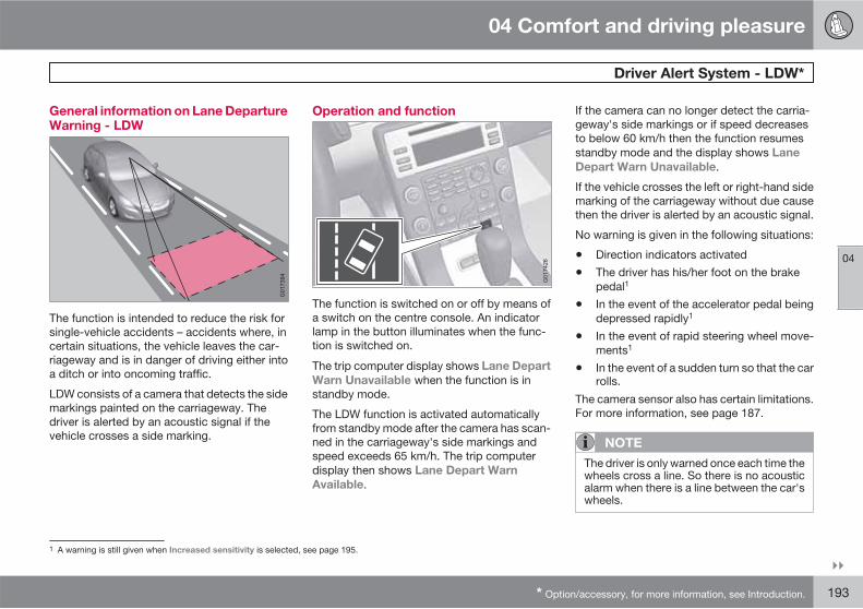
04 Comfort and driving pleasure
Driver Alert System - LDW*
04
��
* Option/accessory, for more information, see Introduction. 193
General information on Lane DepartureWarning - LDW
The function is intended to reduce the risk forsingle-vehicle accidents – accidents where, incertain situations, the vehicle leaves the car-riageway and is in danger of driving either intoa ditch or into oncoming traffic.
LDW consists of a camera that detects the sidemarkings painted on the carriageway. Thedriver is alerted by an acoustic signal if thevehicle crosses a side marking.
Operation and function
The function is switched on or off by means ofa switch on the centre console. An indicatorlamp in the button illuminates when the func-tion is switched on.
The trip computer display shows Lane Depart
Warn Unavailable when the function is instandby mode.
The LDW function is activated automaticallyfrom standby mode after the camera has scan-ned in the carriageway's side markings andspeed exceeds 65 km/h. The trip computerdisplay then shows Lane Depart Warn
Available.
If the camera can no longer detect the carria-geway's side markings or if speed decreasesto below 60 km/h then the function resumesstandby mode and the display shows Lane
Depart Warn Unavailable.
If the vehicle crosses the left or right-hand sidemarking of the carriageway without due causethen the driver is alerted by an acoustic signal.
No warning is given in the following situations:
• Direction indicators activated
• The driver has his/her foot on the brakepedal1
• In the event of the accelerator pedal beingdepressed rapidly1
• In the event of rapid steering wheel move-ments1
• In the event of a sudden turn so that the carrolls.
The camera sensor also has certain limitations.For more information, see page 187.
NOTE
The driver is only warned once each time thewheels cross a line. So there is no acousticalarm when there is a line between the car'swheels.
1 A warning is still given when Increased sensitivity is selected, see page 195.

04 Comfort and driving pleasure
Driver Alert System - LDW*
04
194 * Option/accessory, for more information, see Introduction.
Symbols and messages in the display
Symbol Message Specification
Lane departure warning
On/Off
The function is switched on/off.
Shown at switch-on/off.
The text disappears after 5 seconds.
Lane Depart Warn Unavail-
able
Speed is lower than 60 km/h, the carriageway does not have clear side markings or the camera sensoris temporarily disengaged. Read about the limitations of the camera sensor, see page 187.
Lane Depart Warn Availa-
ble
The function scans the carriageway's side markings.
Windscreen Sensors
blocked
The camera sensor is temporarily disengaged.
Shown in the event of snow, ice or dirt on the windscreen for example.
• Clean the windscreen surface in front of the camera sensor.
Read about the limitations of the camera sensor, see page 187.
Driver Alert Sys Service
required
The system is disengaged.
• Visit a workshop if the message remains - an authorised Volvo workshop is recommended.
04 Comfort and driving pleasure
Driver Alert System - LDW*
04
* Option/accessory, for more information, see Introduction. 195
Personal preferences
See the centre console display with its menusystem and there search for Car settings
Lane departure warning, see page 131.
Select from the options:
On at start up - This option sets the functionin standby mode each time the engine isstarted. Otherwise the same value as when theengine was switched off is obtained.
Increased sensitivity – This option increasessensitivity, an alarm is triggered earlier andfewer limitations apply.
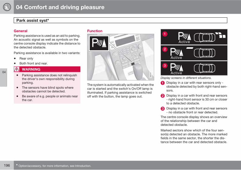
04 Comfort and driving pleasure
Park assist syst*
04
196 * Option/accessory, for more information, see Introduction.
General
Parking assistance is used as an aid to parking.An acoustic signal as well as symbols on thecentre console display indicate the distance tothe detected obstacle.
Parking assistance is available in two variants:
• Rear only
• Both front and rear.
WARNING
• Parking assistance does not relinquishthe driver's own responsibility duringparking.
• The sensors have blind spots whereobstacles cannot be detected.
• Be aware of e.g. people or animals nearthe car.
Function
The system is automatically activated when thecar is started and the switch's On/Off lamp isilluminated. If parking assistance is switchedoff with the button, the lamp goes out.
Active
Active
Active
1
2
3
Display screens in different situations.
Display in a car with rear sensors only -obstacle detected by both right-hand sen-sors.
Display in a car with front and rear sensors- right-hand front sensor is 30 cm or closerto a detected obstacle.
Display in a car with front and rear sensors- no obstacle front or rear detected.
The centre console display shows an overviewof the relationship between the car anddetected obstacle.
Marked sectors show which of the four sen-sor(s) detected an obstacle. The more markedfields in the same sector, the shorter the dis-tance between the car and detected obstacle.
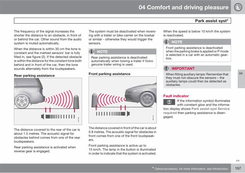
04 Comfort and driving pleasure
Park assist syst*
04
��
* Option/accessory, for more information, see Introduction. 197
The frequency of the signal increases theshorter the distance to an obstacle, in front ofor behind the car. Other sound from the audiosystem is muted automatically.
When the distance is within 30 cm the tone isconstant and the marked sensors' bar is fullyfilled in, see figure (2). If the detected obstacleis within the distance for the constant tone bothbehind and in front of the car, then the tonesounds alternately from the loudspeakers.
Rear parking assistanceG
0178
33
The distance covered to the rear of the car isabout 1.5 metres. The acoustic signal forobstacles behind comes from one of the rearloudspeakers.
Rear parking assistance is activated whenreverse gear is engaged.
The system must be deactivated when revers-ing with a trailer or bike carrier on the towbaror similar - otherwise they would trigger thesensors.
NOTE
Rear parking assistance is deactivatedautomatically when towing a trailer if Volvogenuine trailer wiring is used.
Front parking assistance
G02
1424
The distance covered in front of the car is about0.8 metres. The acoustic signal for obstacles infront comes from one of the front loudspeak-ers.
Front parking assistance is active up to15 km/h. The lamp in the button is illuminatedin order to indicate that the system is activated.
When the speed is below 10 km/h the systemis reactivated.
NOTE
Front parking assistance is deactivatedwhen the parking brake is applied or P modeis selected in a car with an automatic gear-box.
IMPORTANT
When fitting auxiliary lamps: Remember thatthey must not obscure the sensors – theauxiliary lamps could then be detected asobstacles.
Fault indicator
If the information symbol illuminateswith constant glow and the informa-
tion display shows Park assist syst Service
required then parking assistance is disen-gaged.
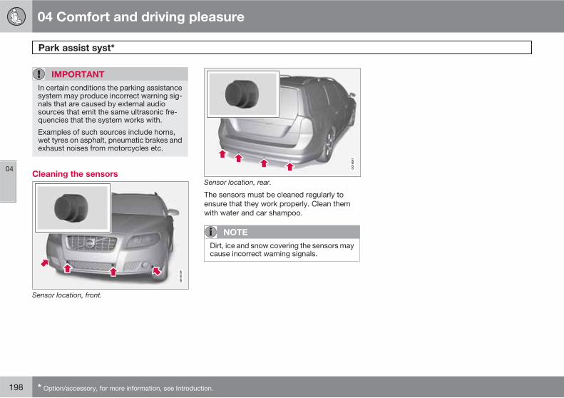
04 Comfort and driving pleasure
Park assist syst*
04
198 * Option/accessory, for more information, see Introduction.
IMPORTANT
In certain conditions the parking assistancesystem may produce incorrect warning sig-nals that are caused by external audiosources that emit the same ultrasonic fre-quencies that the system works with.
Examples of such sources include horns,wet tyres on asphalt, pneumatic brakes andexhaust noises from motorcycles etc.
Cleaning the sensors
Sensor location, front.
Sensor location, rear.
The sensors must be cleaned regularly toensure that they work properly. Clean themwith water and car shampoo.
NOTE
Dirt, ice and snow covering the sensors maycause incorrect warning signals.
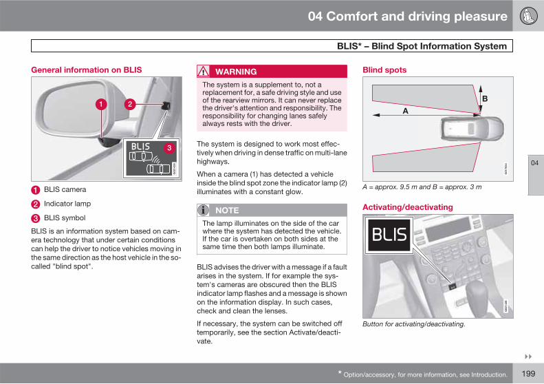
04 Comfort and driving pleasure
BLIS* – Blind Spot Information System
04
��
* Option/accessory, for more information, see Introduction. 199
General information on BLIS
G02
1426
BLIS camera
Indicator lamp
BLIS symbol
BLIS is an information system based on cam-era technology that under certain conditionscan help the driver to notice vehicles moving inthe same direction as the host vehicle in the so-called "blind spot".
WARNING
The system is a supplement to, not areplacement for, a safe driving style and useof the rearview mirrors. It can never replacethe driver's attention and responsibility. Theresponsibility for changing lanes safelyalways rests with the driver.
The system is designed to work most effec-tively when driving in dense traffic on multi-lanehighways.
When a camera (1) has detected a vehicleinside the blind spot zone the indicator lamp (2)illuminates with a constant glow.
NOTE
The lamp illuminates on the side of the carwhere the system has detected the vehicle.If the car is overtaken on both sides at thesame time then both lamps illuminate.
BLIS advises the driver with a message if a faultarises in the system. If for example the sys-tem's cameras are obscured then the BLISindicator lamp flashes and a message is shownon the information display. In such cases,check and clean the lenses.
If necessary, the system can be switched offtemporarily, see the section Activate/deacti-vate.
Blind spots
A = approx. 9.5 m and B = approx. 3 m
Activating/deactivating
Button for activating/deactivating.
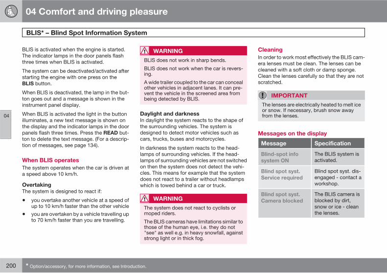
04 Comfort and driving pleasure
BLIS* – Blind Spot Information System
04
200 * Option/accessory, for more information, see Introduction.
BLIS is activated when the engine is started.The indicator lamps in the door panels flashthree times when BLIS is activated.
The system can be deactivated/activated afterstarting the engine with one press on theBLIS button.
When BLIS is deactivated, the lamp in the but-ton goes out and a message is shown in theinstrument panel display.
When BLIS is activated the light in the buttonilluminates, a new text message is shown onthe display and the indicator lamps in the doorpanels flash three times. Press the READ but-ton to delete the text message. (For a descrip-tion of messages, see page 134).
When BLIS operates
The system operates when the car is driven ata speed above 10 km/h.
Overtaking
The system is designed to react if:
• you overtake another vehicle at a speed ofup to 10 km/h faster than the other vehicle
• you are overtaken by a vehicle travelling upto 70 km/h faster than you are travelling.
WARNING
BLIS does not work in sharp bends.
BLIS does not work when the car is revers-ing.
A wide trailer coupled to the car can concealother vehicles in adjacent lanes. It can pre-vent the vehicle in the screened area frombeing detected by BLIS.
Daylight and darkness
In daylight the system reacts to the shape ofthe surrounding vehicles. The system isdesigned to detect motor vehicles such ascars, trucks, buses and motorcycles.
In darkness the system reacts to the head-lamps of surrounding vehicles. If the head-lamps of surrounding vehicles are not switchedon then the system does not detect the vehi-cles. This means for example that the systemdoes not react to a trailer without headlampswhich is towed behind a car or truck.
WARNING
The system does not react to cyclists ormoped riders.
The BLIS cameras have limitations similar tothose of the human eye, i.e. they do not"see" as well e.g. in heavy snowfall, againststrong light or in thick fog.
Cleaning
In order to work most effectively the BLIS cam-era lenses must be clean. The lenses can becleaned with a soft cloth or damp sponge.Clean the lenses carefully so that they are notscratched.
IMPORTANT
The lenses are electrically heated to melt iceor snow. If necessary, brush snow awayfrom the lenses.
Messages on the display
Message Specification
Blind-spot info
system ON
The BLIS system isactivated.
Blind spot syst.
Service required
Blind spot syst. dis-engaged - contact aworkshop.
Blind spot syst.
Camera blocked
The BLIS camera isblocked by dirt,snow or ice - cleanthe lenses.
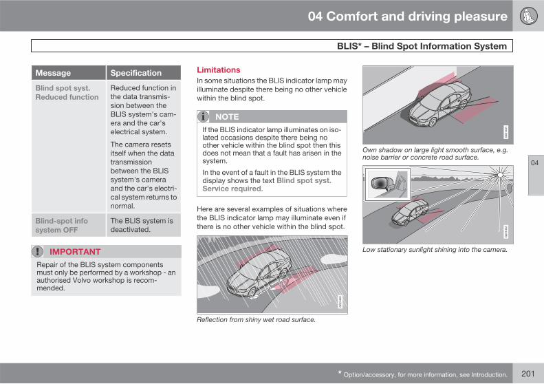
04 Comfort and driving pleasure
BLIS* – Blind Spot Information System
04
* Option/accessory, for more information, see Introduction. 201
Message Specification
Blind spot syst.
Reduced function
Reduced function inthe data transmis-sion between theBLIS system's cam-era and the car'selectrical system.
The camera resetsitself when the datatransmissionbetween the BLISsystem's cameraand the car's electri-cal system returns tonormal.
Blind-spot info
system OFF
The BLIS system isdeactivated.
IMPORTANT
Repair of the BLIS system componentsmust only be performed by a workshop - anauthorised Volvo workshop is recom-mended.
Limitations
In some situations the BLIS indicator lamp mayilluminate despite there being no other vehiclewithin the blind spot.
NOTE
If the BLIS indicator lamp illuminates on iso-lated occasions despite there being noother vehicle within the blind spot then thisdoes not mean that a fault has arisen in thesystem.
In the event of a fault in the BLIS system thedisplay shows the text Blind spot syst.Service required.
Here are several examples of situations wherethe BLIS indicator lamp may illuminate even ifthere is no other vehicle within the blind spot.
Reflection from shiny wet road surface.
Own shadow on large light smooth surface, e.g.noise barrier or concrete road surface.
Low stationary sunlight shining into the camera.
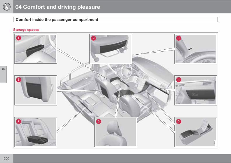
04 Comfort and driving pleasure
Comfort inside the passenger compartment
04
202
Storage spaces
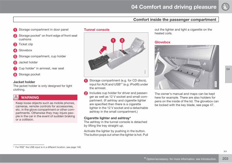
04 Comfort and driving pleasure
Comfort inside the passenger compartment
04
��
* Option/accessory, for more information, see Introduction. 203
Storage compartment in door panel
Storage pocket* on front edge of front seatcushions
Ticket clip
Glovebox
Storage compartment, cup holder
Jacket holder
Cup holder* in armrest, rear seat
Storage pocket
Jacket holder
The jacket holder is only designed for lightclothing.
WARNING
Keep loose objects such as mobile phones,cameras, remote controls for accessories,etc. in the glove compartment or other com-partments. Otherwise they may injure peo-ple in the car in the event of sudden brakingor a collision.
Tunnel console
Storage compartment (e.g. for CD discs),input for AUX and USB*1 (e.g. iPod ) underthe armrest.
Includes cup holder for driver and passen-ger as well as 12 V socket and small com-partment. (If ashtray and cigarette lighterare specified then there is a cigarettelighter in the 12 V socket and a detachableashtray in the small compartment.)
Cigarette lighter and ashtray*
The ashtray in the tunnel console is detachedby lifting the tray straight up.
Activate the lighter by pushing in the button.The button pops out when the lighter is hot. Pull
out the lighter and light a cigarette on theheated coils.
Glovebox
The owner's manual and maps can be kepthere for example. There are also holders forpens on the inside of the lid. The glovebox canbe locked with the key blade, see page 47.
1 For RSE* the USB input is in a different location, see page 148.
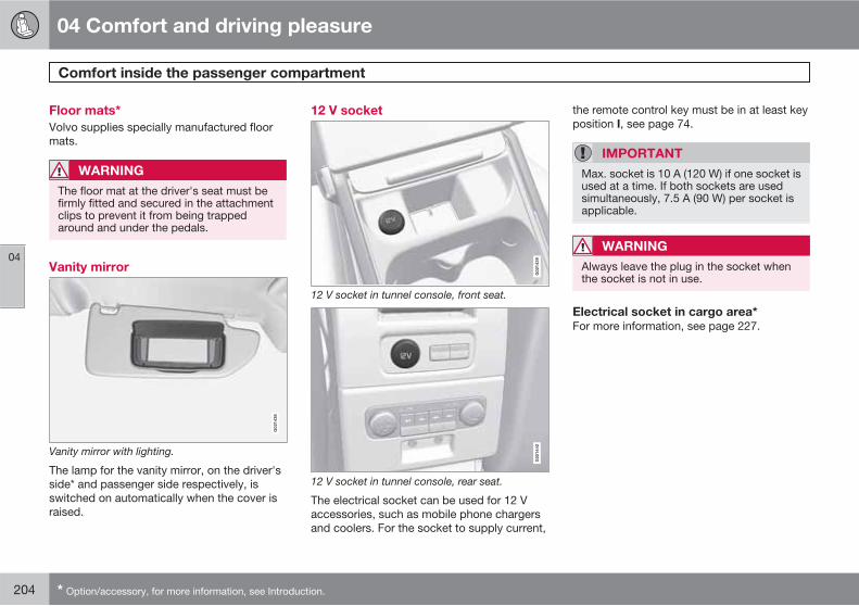
04 Comfort and driving pleasure
Comfort inside the passenger compartment
04
204 * Option/accessory, for more information, see Introduction.
Floor mats*
Volvo supplies specially manufactured floormats.
WARNING
The floor mat at the driver's seat must befirmly fitted and secured in the attachmentclips to prevent it from being trappedaround and under the pedals.
Vanity mirrorG
0214
38
Vanity mirror with lighting.
The lamp for the vanity mirror, on the driver'sside* and passenger side respectively, isswitched on automatically when the cover israised.
12 V socket
G02
1439
12 V socket in tunnel console, front seat.
G02
1440
12 V socket in tunnel console, rear seat.
The electrical socket can be used for 12 Vaccessories, such as mobile phone chargersand coolers. For the socket to supply current,
the remote control key must be in at least keyposition I, see page 74.
IMPORTANT
Max. socket is 10 A (120 W) if one socket isused at a time. If both sockets are usedsimultaneously, 7.5 A (90 W) per socket isapplicable.
WARNING
Always leave the plug in the socket whenthe socket is not in use.
Electrical socket in cargo area*
For more information, see page 227.
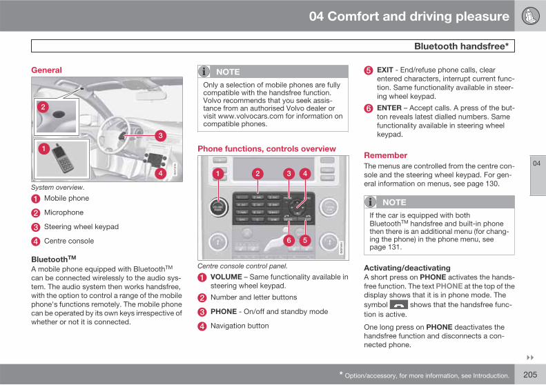
04 Comfort and driving pleasure
Bluetooth handsfree*
04
��
* Option/accessory, for more information, see Introduction. 205
General
System overview.
Mobile phone
Microphone
Steering wheel keypad
Centre console
BluetoothTM
A mobile phone equipped with BluetoothTM
can be connected wirelessly to the audio sys-tem. The audio system then works handsfree,with the option to control a range of the mobilephone's functions remotely. The mobile phonecan be operated by its own keys irrespective ofwhether or not it is connected.
NOTE
Only a selection of mobile phones are fullycompatible with the handsfree function.Volvo recommends that you seek assis-tance from an authorised Volvo dealer orvisit www.volvocars.com for information oncompatible phones.
Phone functions, controls overview
Centre console control panel.
VOLUME – Same functionality available insteering wheel keypad.
Number and letter buttons
PHONE - On/off and standby mode
Navigation button
EXIT - End/refuse phone calls, clearentered characters, interrupt current func-tion. Same functionality available in steer-ing wheel keypad.
ENTER – Accept calls. A press of the but-ton reveals latest dialled numbers. Samefunctionality available in steering wheelkeypad.
Remember
The menus are controlled from the centre con-sole and the steering wheel keypad. For gen-eral information on menus, see page 130.
NOTE
If the car is equipped with bothBluetoothTM handsfree and built-in phonethen there is an additional menu (for chang-ing the phone) in the phone menu, seepage 131.
Activating/deactivating
A short press on PHONE activates the hands-free function. The text PHONE at the top of thedisplay shows that it is in phone mode. Thesymbol shows that the handsfree func-tion is active.
One long press on PHONE deactivates thehandsfree function and disconnects a con-nected phone.
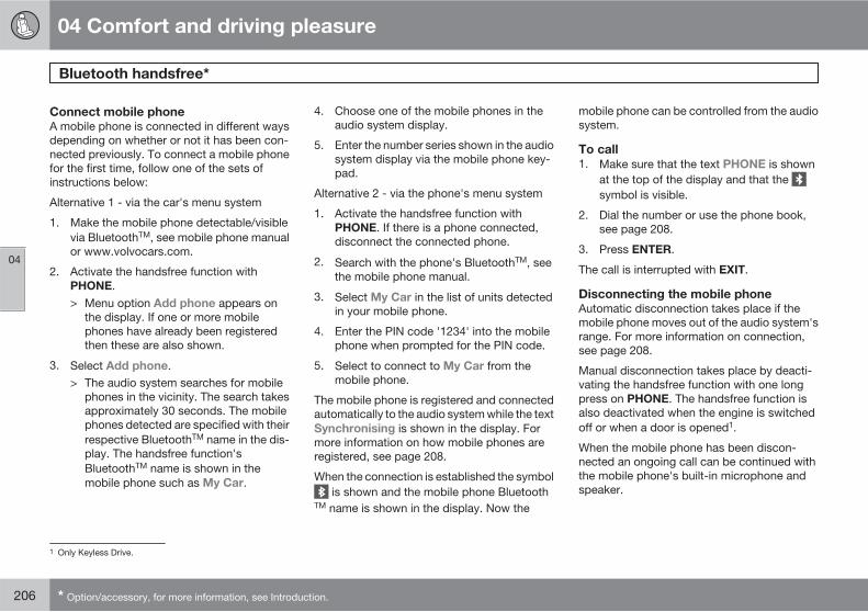
04 Comfort and driving pleasure
Bluetooth handsfree*
04
206 * Option/accessory, for more information, see Introduction.
Connect mobile phone
A mobile phone is connected in different waysdepending on whether or not it has been con-nected previously. To connect a mobile phonefor the first time, follow one of the sets ofinstructions below:
Alternative 1 - via the car's menu system
1. Make the mobile phone detectable/visiblevia BluetoothTM, see mobile phone manualor www.volvocars.com.
2. Activate the handsfree function withPHONE.> Menu option Add phone appears on
the display. If one or more mobilephones have already been registeredthen these are also shown.
3. Select Add phone.> The audio system searches for mobile
phones in the vicinity. The search takesapproximately 30 seconds. The mobilephones detected are specified with theirrespective BluetoothTM name in the dis-play. The handsfree function'sBluetoothTM name is shown in themobile phone such as My Car.
4. Choose one of the mobile phones in theaudio system display.
5. Enter the number series shown in the audiosystem display via the mobile phone key-pad.
Alternative 2 - via the phone's menu system
1. Activate the handsfree function withPHONE. If there is a phone connected,disconnect the connected phone.
2. Search with the phone's BluetoothTM, seethe mobile phone manual.
3. Select My Car in the list of units detectedin your mobile phone.
4. Enter the PIN code '1234' into the mobilephone when prompted for the PIN code.
5. Select to connect to My Car from themobile phone.
The mobile phone is registered and connectedautomatically to the audio system while the textSynchronising is shown in the display. Formore information on how mobile phones areregistered, see page 208.
When the connection is established the symbol is shown and the mobile phone Bluetooth
TM name is shown in the display. Now the
mobile phone can be controlled from the audiosystem.
To call
1. Make sure that the text PHONE is shownat the top of the display and that the symbol is visible.
2. Dial the number or use the phone book,see page 208.
3. Press ENTER.
The call is interrupted with EXIT.
Disconnecting the mobile phone
Automatic disconnection takes place if themobile phone moves out of the audio system'srange. For more information on connection,see page 208.
Manual disconnection takes place by deacti-vating the handsfree function with one longpress on PHONE. The handsfree function isalso deactivated when the engine is switchedoff or when a door is opened1.
When the mobile phone has been discon-nected an ongoing call can be continued withthe mobile phone's built-in microphone andspeaker.
1 Only Keyless Drive.

04 Comfort and driving pleasure
Bluetooth handsfree*
04
��
* Option/accessory, for more information, see Introduction. 207
NOTE
Some mobile phones require that thechangeover from handsfree is confirmedfrom the phone's keypad.
Making and receiving calls
Incoming call
Calls are accepted with ENTER even if theaudio system is in CD or FM mode for example.Refuse or end with EXIT.
Automatic answer
The automatic answer function means thatcalls are accepted automatically.
� Activate/deactivate under Call options
Automatic answer.
In call menu
Press MENU or ENTER during an ongoing callto access the following functions:
• Mute microphone - audio system micro-phone is muted.
• Transfer call to mobile - the call is trans-ferred to the mobile phone.
NOTE
With certain mobile phones the connectionis terminated when the privacy function isused. This is normal. The handsfree functionasks if you want to reconnect.
• Phone book – searching in the phonebook.
NOTE
A new call cannot be started during anongoing call.
Audio settings
Phone call volume
The call volume can be regulated when thehandsfree function is in phone mode. Use thesteering wheel keypad or VOLUME.
Audio system volume
Providing there is no ongoing call taking place,the audio system volume is controlled as usualwith VOLUME. In order to control audio systemvolume during an ongoing call you have toswitch to one of the audio sources.
The audio source can be automatically mutedfor incoming calls under Phone settings
Sounds and volume Mute radio.
Ring volume
Go to Phone settings Sounds and volume
Ring volume and adjust with / on thenavigation button.
Ring signals
The handsfree function has integrated ring sig-nals that can be selected under Phone
settings Sounds and volume Ring
signals Ring signal 1 etc.
NOTE
The connected mobile phone's ring signal isnot deactivated when one of the handsfreesystem's integrated signals is used.
In order to select the connected phone's ringsignal2, go to Phone settings Sounds and
volume Ring signals Use mobile
phone signal.
2 Not supported by all mobile phones.

04 Comfort and driving pleasure
Bluetooth handsfree*
04
208 * Option/accessory, for more information, see Introduction.
More on registering and connecting
A maximum of five mobile phones can be reg-istered. Registration is performed once perphone. After registration the phone no longerneeds to be visible/detectable. A maximum ofone mobile phone can be connected at a time.Phones can be deregistered under Bluetooth
Remove phone.
Automatic connection
When the handsfree function is active and thelast mobile phone connected is in range it isconnected automatically. When the audio sys-tem searches for the last phone connected itsname is shown in the display. To change overto manual connection of another phone, pressEXIT.
Manual connection
If you want to connect a mobile phone otherthan the last connected or change the con-nected mobile phone, proceed as follows:
1. Set the audio system in phone mode.
2. Press PHONE and select one of thephones in the list.
The connection can also be made via the menusystem.
The menu structure is available in two variantsdepending on whether the car only has
BluetoothTM handsfree or if the car also has abuilt-in phone.
• For cars with only BluetoothTM handsfreethe connection is made under Main menu
Bluetooth Bluetooth Connect
phone or Main menu Bluetooth
Bluetooth Change phone Add
phone.
• For cars with built-in phone andBluetoothTM handsfree the connection ismade under Main menu Bluetooth
Bluetooth Connect phone or Main
menu Bluetooth Change phone
Add phone.
Phone book
All use of the phone book presupposes that thetext PHONE is shown at the top of the displayand that the symbol is visible.
The audio system stores a copy of the phonebook from each registered mobile phone. Thephone book is copied automatically to theaudio system during each connection.
� Deactivate the function under Phone
settings Synchronise phone book.Searching for contacts is only performed inthe connected mobile phone's phonebook.
NOTE
If the mobile phone does not support copy-ing of the phone book then List is empty isshown when copying is finished.
If the phone book contains a ringing caller'scontact information then this is shown in thedisplay.
Searching for contacts
The easiest way to search in the phone book iswith long presses on the keys 2–9. This startsa search in the phone book based on the key'sfirst letter.
The phone book can also be reached with / on the navigation button or with / on
the steering wheel keypad. The search can alsobe performed from the phone book's Searchmenu under Phone book Search:
1. Enter the first few letters of the contact andpress ENTER, or simply press ENTER.
2. Scroll to a contact and press ENTER tocall.
Voice recognition
The mobile phone's voice recognition functionfor dialling can be used by holding in ENTER.

04 Comfort and driving pleasure
Bluetooth handsfree*
04
* Option/accessory, for more information, see Introduction. 209
NOTE
Only a selection of mobile phones are fullycompatible with the voice recognition func-tion. Volvo recommends that you contact anauthorised Volvo dealer or visitwww.volvocars.com for information oncompatible phones.
Voice mail number
Voice mail number can be changed under Call
options Voice mail number. If there is nonumber stored then this menu can be reachedwith one long press on 1. Press 1 for a long timeto use the stored number.
Call lists
The call lists are copied to the handsfree func-tion at each new connection and are thenupdated during the connection. Press ENTER
to show the last dialled. Other call lists areavailable under Call register.
NOTE
Certain mobile phones show a list of the lastdialled calls in reverse order.
Inputting text
Input text using the keypad in the centre con-sole. Press once for the key's first character,
twice for the second etc. Continue pressing formore characters, see the following table.
A short press on EXIT deletes an input char-acter. One long press on EXIT clears all inputcharacters. / on the navigation buttonscrolls between the characters.
Key Function
Space . 1 - ? ! , : " ' ( )
A B C 2 Ä Å À Æ Ç
D E F 3 È É
G H I 4 Ì
J K L 5
M N O 6 Ñ Ö Ò Ø
P Q R S 7 ß
T U V 8 Ü Ù
W X Y Z 9
Key Function
Pressed briefly if two charactersshall be entered after each otherwith the same key.
+ 0 @ * # & $ £ / %
Shift between upper and lowercase letter
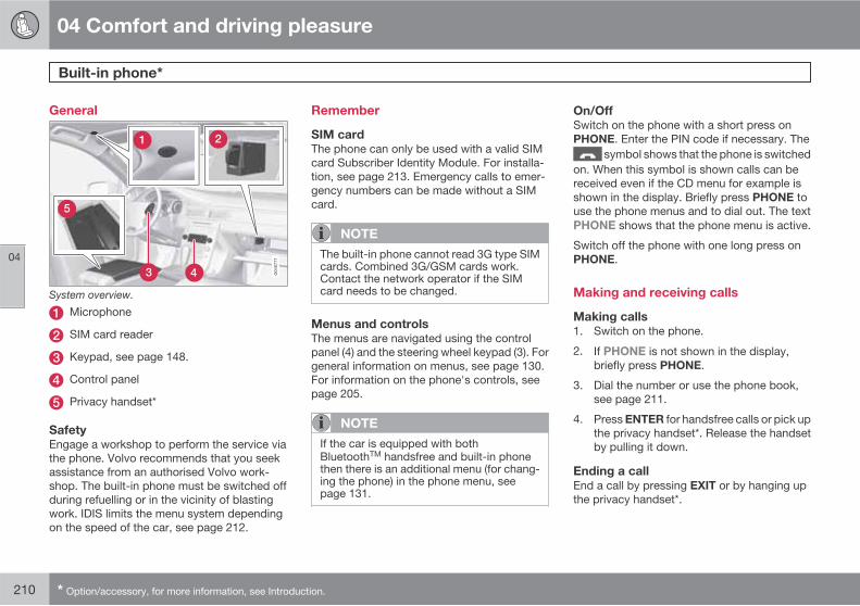
04 Comfort and driving pleasure
Built-in phone*
04
210 * Option/accessory, for more information, see Introduction.
General
System overview.
Microphone
SIM card reader
Keypad, see page 148.
Control panel
Privacy handset*
Safety
Engage a workshop to perform the service viathe phone. Volvo recommends that you seekassistance from an authorised Volvo work-shop. The built-in phone must be switched offduring refuelling or in the vicinity of blastingwork. IDIS limits the menu system dependingon the speed of the car, see page 212.
Remember
SIM card
The phone can only be used with a valid SIMcard Subscriber Identity Module. For installa-tion, see page 213. Emergency calls to emer-gency numbers can be made without a SIMcard.
NOTE
The built-in phone cannot read 3G type SIMcards. Combined 3G/GSM cards work.Contact the network operator if the SIMcard needs to be changed.
Menus and controls
The menus are navigated using the controlpanel (4) and the steering wheel keypad (3). Forgeneral information on menus, see page 130.For information on the phone's controls, seepage 205.
NOTE
If the car is equipped with bothBluetoothTM handsfree and built-in phonethen there is an additional menu (for chang-ing the phone) in the phone menu, seepage 131.
On/Off
Switch on the phone with a short press onPHONE. Enter the PIN code if necessary. The
symbol shows that the phone is switchedon. When this symbol is shown calls can bereceived even if the CD menu for example isshown in the display. Briefly press PHONE touse the phone menus and to dial out. The textPHONE shows that the phone menu is active.
Switch off the phone with one long press onPHONE.
Making and receiving calls
Making calls
1. Switch on the phone.
2. If PHONE is not shown in the display,briefly press PHONE.
3. Dial the number or use the phone book,see page 211.
4. Press ENTER for handsfree calls or pick upthe privacy handset*. Release the handsetby pulling it down.
Ending a call
End a call by pressing EXIT or by hanging upthe privacy handset*.

04 Comfort and driving pleasure
Built-in phone*
04
��
* Option/accessory, for more information, see Introduction. 211
Incoming call
Press ENTER for handsfree calls or pick up theprivacy handset*. If the privacy handset* is offthe hook when the phone rings then calls mustbe received using ENTER.
End calls by pressing EXIT or by hanging upthe privacy handset*. Refuse calls using EXIT.
Automatic answer
See page 207.
Call waiting
The function enables a new call to be answeredduring an ongoing call. The new call isanswered as usual and the previous call is puton hold.
� Activate/deactivate under Call options
Call waiting.
Automatic diversions
Incoming calls can be diverted automaticallydepending on the type of call and situation.
� Activate/deactivate under Call options
Diversions.
During a call
Press MENU or ENTER during a call to accessthe In-call menu.
To call
1. Put the call on hold under Hold.
2. Dial the number of the third party or use thePhone book menu option.
Switch between calls using the Swap menuoption.
Conference call
A conference call consists of several parties. Itcan be initiated when a call is underway andanother is on hold. The Join menu option startsthe conference call.
All ongoing calls are disconnected if the con-ference call is terminated.
Switching between the privacy handset*
and handsfree
Switch from handsfree to the privacy hand-set* by picking up the privacy handset orselecting in the menu.
Switch from the privacy handset* to handsfreeusing the Handsfree menu option.
Mute mode
Mute mode involves deactivating the micro-phone, see page 210.
� Activate/deactivate the microphone usingthe Microphone on/Mute microphone
menu option.
Audio settings
Phone call volume
The phone uses the front door speakers. Callvolume can be controlled when the textPHONE is shown at the top of the display.
� Use the steering wheel keypad orVOLUME.
Audio system volume
See page 149.
Signals and volume
Change the ring signal under Phone settings
Sounds and volume Ring signals.
Activate/deactivate the message beep underPhone settings Sounds and volume
Message beep.
Control the ring volume under Phone settings
Sounds and volume Ring volume.Adjust using / on the navigation button.
04 Comfort and driving pleasure
Built-in phone*
04
212 * Option/accessory, for more information, see Introduction.
Phone book
Contact information can be stored on the SIMcard or in the phone.
Storing contacts in the phone book
1. Press MENU and scroll to Phone book
New contact.
2. Enter a name and press ENTER. For infor-mation on text input, see below.
3. Enter a number and press ENTER.
4. Scroll to SIM card or Phone memory andpress ENTER.
Inputting text
See page 209.
Searching for contacts
See page 208.
Erasing contacts
Erase a contact in the phone book by selectingit and pressing ENTER. Then scroll to Erase
and press ENTER.
Erase all contacts under Phone book Erase
SIM or Erase phone.
Copying entries between the SIM card
and the phone book
Go to Phone book Copy all SIM to
phone or Phone to SIM and press ENTER.
Voice mail number
See page 209.
Other functions and settings
IDIS
IDIS (Intelligent Driver Information System)can, in active driving situations, delay or refusering signals from incoming calls. This way lessattention is distracted from driving.
� IDIS is deactivated under Phone settings
IDIS.
Reading messages
1. Scroll to Messages Read and pressENTER.
2. Scroll to a message and press ENTER.
3. The message text is shown in the display.Additional selections can be made bypressing ENTER.
Writing and sending messages
1. Scroll to Messages Write new andpress ENTER.
2. Enter text and press ENTER. For informa-tion on text input, see page 209.
3. Scroll to Send and press ENTER.
4. Enter a phone number and press ENTER.
Message settings
Message settings are not normally changed.The network provider has further informationon these settings. There are three optionsunder Messages Message settings:
• SMSC number - Specifies the messagecentre which will transfer the messages.
• Validity time - Specifies how long themessage will be stored in the messagecentre.
• Message type.
Call lists
Lists of received, dialled and missed calls arestored in Call register. Dialled calls are alsoshown by pressing ENTER. The phone num-bers in the lists can be saved in the phonebook.
Call duration
Call duration is stored under Call register
Call duration.
� Reset the values under Call register
Call duration Reset timers.
Show/hide number for third party
The phone number can be temporarily hiddenunder Call options Send my number.
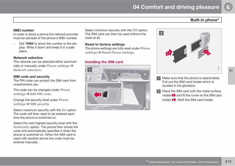
04 Comfort and driving pleasure
Built-in phone*
04
* Option/accessory, for more information, see Introduction. 213
IMEI number
In order to block a phone the network providermust be advised of the phone's IMEI number.
� Dial *#06# to show the number in the dis-play. Write it down and keep it in a safeplace.
Network selection
The network can be selected either automati-cally or manually under Phone settings
Network selection.
SIM code and security
The PIN code can protect the SIM card fromunauthorised use.
The code can be changed under Phone
settings Edit PIN code.
Change the security level under Phone
settings SIM security.
Select maximum security with the On option.The code will then need to be entered eachtime the phone is switched on.
Select the next highest security level with theAutomatic option. The phone then stores thecode and automatically specifies it when thephone is switched on. When the SIM card isused with another phone the code must beentered manually.
Select minimum security with the Off option.The SIM card can then be used without thecode at all.
Reset to factory settings
The phone settings are fully reset under Phone
settings Reset Phone settings.
Installing the SIM card
G02
1450
G02
1451
Make sure that the phone is deactivated.Pull out the SIM card holder which islocated in the glovebox.
Place the SIM card with the metal surfacevisible and fit the cover on the SIM cardholder . Refit the SIM card holder.
214
Recommendations during driving......................................................... 216Refuelling.............................................................................................. 219Fuel....................................................................................................... 220Loading................................................................................................. 224Cargo area............................................................................................ 228Driving with a trailer.............................................................................. 231Towing and recovery............................................................................. 237
DURING YOUR JOURNEY

05 During your journey
Recommendations during driving
05
216
General
Economical driving
Driving economically means driving smoothlywhile thinking ahead and adjusting your drivingstyle and speed to the prevailing conditions.
• Avoid driving with open windows.
• Do not use winter tyres when the winterseason is over.
• Avoid sudden unnecessary accelerationand heavy braking.
• Remove unnecessary items from the car -the greater the load the higher the fuel con-sumption.
• Use engine braking to slow down, when itcan take place without risk to other roadusers.
• Drive in the highest gear possible, adaptedto the current traffic situation and road -lower engine speeds result in lower fuelconsumption.
• A roof load and ski box increase air resis-tance, leading to higher fuel consumption- remove the load carriers when not in use.
• Do not run the engine to operating tem-perature at idling speed, but rather drivewith a light load as soon as possible - acold engine consumes more fuel than awarm one.
• The V70 with the D5 engine and 6-speedmanual transmission is started in 2nd gearunder normal conditions.
For more information and further advice, seethe pages 11 and 306.
WARNING
Never switch off the engine while moving,such as downhill, this deactivates importantsystems such as the power steering andbrake servo.
Driving in water
The car can be driven through water at a maxi-mum depth of 25 cm at a maximum speed of10 km/h. Extra caution should be exercisedwhen passing through flowing water.
During driving in water, maintain a low speedand do not stop the car. When the water hasbeen passed, depress the brake pedal lightlyand check that full brake function is achieved.Water and mud for example can make thebrake linings wet resulting in delayed brakefunction.
• Clean the electric contacts of the electricengine block heater and trailer couplingafter driving in water and mud.
• Do not let the car stand with water over thesills for any long period of time - this couldcause electrical malfunctions.
IMPORTANT
Engine damage can occur if water entersthe air filter.
In depths greater than 25 cm, water couldenter the transmission. This reduces thelubricating ability of the oils and shortensthe service life of these systems.
In the event of the engine stalling in water,do not try restart - tow the car from the waterto a workshop - an authorised Volvo work-shop is recommended. Risk of enginebreakdown.
Engine, gearbox and cooling system
Under special conditions, for example harddriving in hilly terrain and hot climate, there isa risk that the engine and drive system mayoverheat - in particular with a heavy load.
For information about overheating when driv-ing with a trailer, see page 231.
• Remove any auxiliary lamps from in frontof the grille when driving in hot climates.
• If the temperature in the engine's coolingsystem is too high the instrument panel'swarning symbol is illuminated and there isa text message displayed there High
engine temp Stop safely - stop the car ina safe way and allow the engine to run atidling speed for several minutes to cooldown.
05 During your journey
Recommendations during driving
05
��
217
• If the text message High engine temp
Stop engine or Coolant level low, Stop
engine is shown then the engine must beswitched off after stopping the car.
• In the event of overheating in the gearboxa built-in protection function is activatedwhich, amongst other things, illuminatesthe instrument panel's warning symbol andthere is a text message displayed thereTransmission hot Reduce speed orTransmission hot Stop safely - followthe recommendation given and lower thespeed and stop the car in a safe way andallow the engine to run at idling speed fora few minutes to allow the gearbox to cooldown.
• If the car overheats, the air conditioningmay be switched off temporarily.
• Do not turn the engine off immediately youstop after a hard drive.
NOTE
It is normal for the engine's cooling fan tooperate for a while after the engine has beenswitched off.
Open tailgate
WARNING
Do not drive with the tailgate open. Toxicexhaust fumes could be drawn into the carthrough the cargo area.
Do not overload the battery
The electrical functions in the car load the bat-tery to varying degrees. Avoid using the keyposition II when the engine is switched off.Instead use the I mode - which uses lesspower.
Also, be aware of different accessories thatload the electrical system. Do not use functionswhich use a lot of power when the engine isswitched off. Examples of such functions are:
• ventilation fan
• windscreen wiper
• audio system (high volume)
• headlamps.
If the battery voltage is low the information dis-play shows the text Low battery Power save
mode. The energy-saving function then shutsdown certain functions or reduces certainfunctions such as the ventilation fan and/oraudio system.
� In which case, charge the battery by star-ting the engine and then running it for at
least 15 minutes - battery charging is moreeffective during driving than running theengine at idling speed while stationary.
Before a long journey
• Check that the engine is working normallyand that fuel consumption is normal.
• Make sure that there are no leaks (fuel, oilor other fluid).
• Check all bulbs and tyre tread depths.
• Carrying a warning triangle is a legalrequirement in certain countries.
Winter driving
Check the following in particular before thecold season:
• The engine coolant must contain at least50% glycol. This mixture protects theengine against frost erosion down toapproximately –35 °C. To achieve optimumantifreeze protection, different types of gly-col must not be mixed.
• The fuel tank must be kept filled to preventcondensation.
• Engine oil viscosity is important. Oils withlower viscosity (thinner oils) facilitate star-ting in cold weather and also reduce fuelconsumption while the engine is cold. Formore information on suitable oils, seepage 301.
05 During your journey
Recommendations during driving
05
218
IMPORTANT
Low viscosity oil must not be used for harddriving or in hot weather.
• The condition of the battery and chargelevel must be inspected. Cold weather pla-ces great demands on the battery and itscapacity is reduced by the cold.
• Use washer fluid to avoid ice forming in thewasher fluid reservoir.
To achieve optimum roadholding Volvo rec-ommends using winter tyres on all four wheelsif there is a risk of snow or ice.
NOTE
The use of winter tyres is a legal requirementin certain countries. Studded tyres are notpermitted in all countries.
Slippery driving conditions
Practise driving on slippery surfaces undercontrolled conditions to learn how the carreacts.
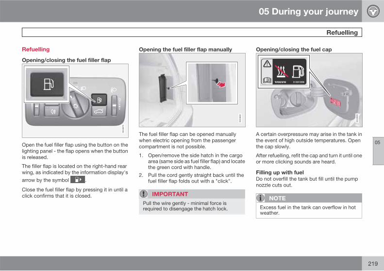
05 During your journey
Refuelling
05
219
Refuelling
Opening/closing the fuel filler flap
Open the fuel filler flap using the button on thelighting panel - the flap opens when the buttonis released.
The filler flap is located on the right-hand rearwing, as indicated by the information display'sarrow by the symbol .
Close the fuel filler flap by pressing it in until aclick confirms that it is closed.
Opening the fuel filler flap manually
The fuel filler flap can be opened manuallywhen electric opening from the passengercompartment is not possible.
1. Open/remove the side hatch in the cargoarea (same side as fuel filler flap) and locatethe green cord with handle.
2. Pull the cord gently straight back until thefuel filler flap folds out with a "click".
IMPORTANT
Pull the wire gently - minimal force isrequired to disengage the hatch lock.
Opening/closing the fuel cap
A certain overpressure may arise in the tank inthe event of high outside temperatures. Openthe cap slowly.
After refuelling, refit the cap and turn it until oneor more clicking sounds are heard.
Filling up with fuel
Do not overfill the tank but fill until the pumpnozzle cuts out.
NOTE
Excess fuel in the tank can overflow in hotweather.

05 During your journey
Fuel
05
220
General information on fuel
Fuel of a lower quality than that recommendedby Volvo must not be used as engine powerand fuel consumption is negatively affected.
WARNING
Always avoid inhaling fuel vapour and get-ting fuel splashes in the eyes.
In the event of fuel in the eyes, remove anycontact lenses and rinse the eyes in plentyof water for at least 15 minutes and seekmedical attention.
Never swallow fuel. Fuels such as petrol,bioethanol and mixtures of them and dieselare highly toxic and could cause permanentinjury or be fatal if swallowed. Seek medicalattention immediately if fuel has been swal-lowed.
WARNING
Fuel which spills onto the ground can beignited.
Switch off the fuel-driven heater before star-ting to refuel.
Never carry an activated mobile phonewhen refuelling. The ring signal could causespark build-up and ignite petrol fumes,leading to fire and injury.
IMPORTANT
Mixing different types of fuel or the use offuel not recommended invalidates Volvo'sguarantees, and any associated serviceagreement. This applies to all engines.NOTE: It does not apply to cars with enginesthat are adapted to run on ethanol fuel (E85).
NOTE
Extreme weather conditions, driving with atrailer or driving at high altitudes in combi-nation with fuel grade are factors that couldaffect the car's performance.
Catalytic converters
The purpose of the catalytic converters is topurify exhaust gases. They are located close tothe engine so that operating temperature isreached quickly.
The catalytic converters consist of a monolith(ceramic or metal) with channels. The channelwalls are lined with a thin layer of platinum/rho-dium/palladium. These metals act as catalysts,i.e. they participate in and accelerate a chem-ical reaction without being used up them-selves.
Lambda-sondTM oxygen sensor
The Lambda-sond is part of a control systemintended to reduce emissions and improve fueleconomy.
An oxygen sensor monitors the oxygen contentof the exhaust gases leaving the engine. Thisvalue is fed into an electronic system that con-tinuously controls the injectors. The ratio of fuelto air directed to the engine is continuouslyadjusted. These adjustments create optimalconditions for efficient combustion, andtogether with the three-way catalytic converterreduce harmful emissions (hydrocarbons, car-bon monoxide and nitrous oxides).
Petrol
Petrol must meet the EN 228 standard. Mostengines can be run with octane ratings of 95and 98 RON. 91 RON should only be used inexceptional cases.
• 95 RON can be used for normal driving.
• 98 RON is recommended for optimum per-formance and minimum fuel consumption.
When driving in temperatures above +38 °C,fuel with the highest possible octane rating isrecommended for optimum performance andfuel economy.

05 During your journey
Fuel
05
��
221
IMPORTANT
• Always refuel with unleaded petrol so asnot to damage the catalytic converter.
• Do not use additives not recommendedby Volvo.
Bioethanol E85
Do not modify the fuel system or its compo-nents, and do not replace components withparts that are not specifically designed for usewith bioethanol.
WARNING
Methanol must not be used. A decal on theinside of the fuel filler flap shows the correctalternative fuel.
The use of components not designed forbioethanol engines could cause fire, injuryor engine damage.
Reserve fuel can
The reserve fuel can should be filled with petrol,see the NOTE box, page 109.
IMPORTANT
Make sure the reserve fuel can is securelyfastened and that its cap is sealed.
WARNING
Ethanol is sensitive to sparks, and explosivegases could form in the reserve fuel can if itis refuelled with ethanol.
Diesel
Diesel must fulfil the EN 590 or JIS K2204standards. Diesel engines are sensitive to con-taminants, such as excessively high volumesof sulphur particles for example. Only use die-sel fuel from well-known producers. Never usediesel of dubious quality.
At low temperatures (-6 °C to -40 °C), a paraffinprecipitate may form in the diesel fuel, whichmay lead to ignition problems. Special dieselfuel designed for low temperatures aroundfreezing point is available from the major oilcompanies. This fuel is less viscous at low tem-peratures and reduces the risk of paraffin pre-cipitate.
The risk of condensation in the fuel tank isreduced if the tank is kept well filled. When
refuelling, check that the area around the fuelfiller pipe is clean. Avoid spilling fuel onto thepaintwork. Wash off any spillage with deter-gent and water.
IMPORTANT
Only ever use fuel that fulfils the Europeandiesel standard.
The sulphur content must be a maximum of50 ppm.
IMPORTANT
Diesel type fuels which must not be used:
• Special additives
• Marine Diesel Fuel
• Fuel oil
• RME1 (Rape Methyl Ester) and vegeta-ble oil.
These fuels do not fulfil the requirements inaccordance with Volvo recommendationsand generate increased wear and enginedamage that is not covered by the Volvowarranty.
Empty tank
The design of the fuel system in a diesel enginemeans that if the vehicle runs out of fuel, the
1 Diesel fuel may contain a certain amount of RME, but further amounts must not be added.

05 During your journey
Fuel
05
222 * Option/accessory, for more information, see Introduction.
tank may need to be vented in the workshop inorder to restart the engine after fuelling.
Once the engine has stopped due to fuel star-vation, the fuel system needs a few momentsto carry out a check. Do this before starting theengine, once the fuel tank has been filled withdiesel:
1. Place the remote key in the ignition switchand push it gently so that it is pulled in (seepage 74).
2. Press the START button without depress-ing the brake and/or clutch pedal.
3. Wait approx. 1 minute.4. To start the engine: Depress the brake and/
or clutch pedal and then press theSTART button again.
Draining condensation from the fuel filter
The fuel filter separates condensation from thefuel. Condensation can disrupt engine opera-tion.
The fuel filter must be drained at the intervalsspecified in the Service and Warranty Bookletor if you suspect that the car has been filledwith contaminated fuel.
IMPORTANT
Certain special additives remove the waterseparation in the fuel filter.
Diesel particle filter (DPF)
Diesel cars are equipped with a particle filter,which results in more efficient emission con-trol. The particles in the exhaust gases are col-lected in the filter during normal driving. So-called "regeneration" is started in order to burnaway the particles and empty the filter. Thisrequires the engine to have reached normaloperating temperature.
Regeneration of the filter takes place automat-ically at an interval of approximately300-900 km depending on driving conditions.Regeneration normally takes 10-20 minutes. Itmay take a little longer at a low average speed.Fuel consumption may increase slightly duringregeneration.
Regeneration in cold weather
If the car is frequently driven short distances incold weather then the engine does not reachnormal operating temperature. This means thatregeneration of the diesel particle filter doesnot take place and the filter is not emptied.
When the filter has become approximately80% full of particles, a warning triangle on theinstrument panel illuminates, and the messageSoot filter full. See manual is shown on theinstrument panel display.
Start regeneration of the filter by driving the caruntil the engine reaches normal operating tem-perature, preferably on a main road or motor-
way. The car should then be driven for approx-imately 20 minutes more.
NOTE
A smaller reduction of engine power may benoticed temporarily during regeneration.
When regeneration is complete the warningtext is cleared automatically.
Use the parking heater* in cold weather so thatthe engine reaches normal operating tempera-ture more quickly.
IMPORTANT
If the filter fills up with particles then it canbe difficult to start the engine and the filterwill be incapable of functioning. Then thereis a risk that the filter will have to bereplaced.
Fuel consumption and emissions ofcarbon dioxide
Fuel consumption figures may change if the caris equipped with extra equipment that affectsthe car's weight. See information on weightspage 293 and table page 304.
The manner in which the car is driven, andother non-technical factors can also affect fuelconsumption.

05 During your journey
Fuel
05
223
Consumption is higher and power output lowerfor fuel with an octane rating of 91 RON.
NOTE
Extreme weather conditions, driving with atrailer or driving at high altitudes in combi-nation with fuel grade are factors that couldaffect the car's performance.

05 During your journey
Loading
05
224
General information on loading
Payload depends on the car's kerb weight. Thetotal of the weight of the passengers and allaccessories reduces the car's payload by acorresponding weight. For more detailed infor-mation on weights, see page 293.
The tailgate is opened via a button onthe lighting panel or the remote con-
trol key, see page 57.
WARNING
The car's driving characteristics changedepending on the weight and distribution ofthe load.
To bear in mind when loading
• Position the load firmly against the back-rest in front.
• Put wide loads in the centre.
• Heavy objects should be placed as low aspossible. Avoid placing heavy loads onlowered backrests.
• Cover sharp edges with something soft toavoid damaging the upholstery.
• Secure all loads to the load retaining eye-lets with straps or web lashings.
WARNING
A loose object weighing 20 kg can, in afrontal collision at a speed of 50 km/h, carrythe impact of an item weighing 1000 kg.
WARNING
The protection provided by the inflatablecurtain in the headlining may be compro-mised or eliminated by high loads.
• Never load cargo above the backrest.
WARNING
Always secure the load. During heavy brak-ing the load may otherwise shift, causinginjury to the car's occupants.
Cover sharp edges and sharp corners withsomething soft.
Switch off the engine and apply the parkingbrake when loading/unloading long items.Otherwise you may accidentally knock thegear lever or gear selector with the load intoa drive position - and the car could thenmove off.
Front seat
The passenger seat backrest can also befolded for an extra long load, see page 76.
Roof load
Using load carriers
To avoid damaging the car and for maximumpossible safety while driving, the load carriersdesigned by Volvo are recommended.
Carefully follow the installation instructionssupplied with the carriers.
• Check periodically that the load carriersand load are properly secured. Lash theload securely with retaining straps.
• Distribute the load evenly over the loadcarriers. Put the heaviest objects at thebottom.
• The size of the area exposed to the wind,and therefore fuel consumption, increasewith the size of the load.
• Drive gently. Avoid quick acceleration,heavy braking and hard cornering.
WARNING
The car's centre of gravity and driving cha-racteristics are altered by roof loads. Forinformation on maximum permitted roofload, including load carriers and any spacebox, see page 293.

05 During your journey
Loading
05
��
225
Lowering the rear seat backrest
To simplify loading in the cargo area, the rearseat backrest can be folded down, seepage 78.
Securing loads
On both sides of the cargo area there are sev-eral mounting points designed for securingloads. They are located in the floor and in thetop edge of both sides of the cargo area.
WARNING
Hard, sharp and/or heavy objects that areloose or protrude could cause injury duringheavy braking.
Always secure large and heavy objects witha seatbelt or cargo retaining straps.
Floor rails
Load secured in both upper and lower mountingpoints.
In the floor of the cargo area there are two railswith movable cargo retaining hooks for secur-ing items in the cargo area using cargo retain-ing straps.
IMPORTANT
Do not use other adjustable straps as thesecould pull and break the mounting points.
Cleaning
Dirt and objects collecting down in the railscould hinder the repositioning, locking, raisingand removal of the cargo retaining hooks.Make it a habit to clean the tracks with a vac-uum cleaner and a lightly-moistened soft cloth.
Cargo retaining straps
G01
9397
Strap retention.
One loop of the cargo retaining strap aroundone of the cargo retaining hooks secures thestrap and prevents it from sliding around thehook.
NOTE
A suitable width for a cargo retaining strapis approx. 25 mm.
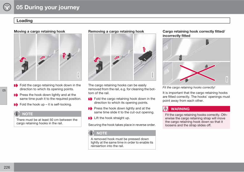
05 During your journey
Loading
05
226
Moving a cargo retaining hook
G01
7742
Fold the cargo retaining hook down in thedirection to which its opening points.
Press the hook down lightly and at thesame time push it to the required position.
Fold the hook up – it is self-locking.
NOTE
There must be at least 50 cm between thecargo retaining hooks in the rail.
Removing a cargo retaining hook
G01
8134
The cargo retaining hooks can be easilyremoved from the rail, e.g. for cleaning the bot-tom of the rail.
Fold the cargo retaining hook down in thedirection to which its opening points.
Press the hook down lightly and at thesame time slide it to the cut-out opening.
Lift the hook straight up.
Securing the hook takes place in reverse order.
NOTE
A removed hook must be pressed downlightly at the same time in order to enable itsreinsertion into the rail.
Cargo retaining hook correctly fitted/
incorrectly fitted
G01
9581
Fit the cargo retaining hooks correctly!
It is important that the cargo retaining hooksare fitted correctly. The hooks' openings mustpoint away from each other.
WARNING
Fit the cargo retaining hooks correctly. Oth-erwise the cargo retaining strap will movethe cargo retaining hook down so that itloosens and the strap slides off.

05 During your journey
Loading
05
* Option/accessory, for more information, see Introduction. 227
Bag holder*
G01
7745
Bag holder under folding hatch in the floor.
The bag holder keeps carrier bags in place andprevents them from overturning and spreadingtheir contents across the cargo area.
1. Fold up the holder, which is part of the floorhatch.
2. Fasten the bags with strap and secure thecarrying handle in the hooks.
12 V electrical socket*
G01
7825
Lower the cover to access the electricalsocket. The socket also provides voltage whenthe remote control key is not in the ignitionswitch.
NOTE
Remember not to use the electrical socketwith the engine switched off because of therisk of discharging the car's battery.

05 During your journey
Cargo area
05
228 * Option/accessory, for more information, see Introduction.
Safety net*
Storage space, safety net cassettes.
A rollable safety net comprising two cassetteshas a storage space under the cargo area floorhatch.
Securing the net cassettes
The two-part safety net cassette is secured onthe rear of the backrest. The narrowest cas-sette is secured on the left-hand side (seenfrom the tailgate).
1. Fold the rear seat's backrest forward, seepage 79.
2. Align the cassette's anchor rails in front ofthe backrest attachment lugs .
3. Slide the cassette into the attachment lugs.
4. Fold back and lock the backrests.
• Removing the cassettes takes place inreverse order.
Using the safety net
G01
8246
Pull the net up from the cassettes. The net isself-locking after about 1 minute if the rearseat's backrests are raised.
Pull up the right-hand section of the netusing its strap.
Insert the rod in the mounting on the right-hand side and then press it forward – therod locks in with a click.
Pull out the rod's telescope section andclick it in on the other side.
Pull up the left-hand safety net and hook itinto the rod.
• Folding up takes place in reverse order.
The net can also be used when the rear seat'sbackrests are folded forward.
Removing the net cassettes
1. Roll the safety nets into the cassettes inaccordance with the procedure in the sec-tion entitled "Using the safety net", but inreverse.
2. Fold the whole backrest forward.
3. Slide the cassettes out until they loosenfrom the anchor rails.
Store the cassettes in their compartment underthe cargo area floor hatch.

05 During your journey
Cargo area
05
��
* Option/accessory, for more information, see Introduction. 229
WARNING
Loads in the cargo area must be firmlysecured, even if the safety net is correctlyfitted.
Safety net combined with cargo cover
G01
8247
Puller-straps for raising the net.
The safety net can also be raised from the rearseat when the cargo cover is extended.
Follow the procedure in the section entitled"Using the safety net". The straps for raisingare located by the arrows.
Safety grille*
G01
7748
A safety grille prevents loads or pets frombeing thrown forward in the passenger com-partment in the event of sudden braking.
Folding up
Take hold of the bottom of the safety grille andpull back/up.
IMPORTANT
The safety grille cannot be folded up ordown when a cargo cover is fitted.
Fitting/removal
The safety grille is normally permanently instal-led in the car because it can easily be foldedup in the roof and so be out of the way if alonger cargo area is required. However, if
desired, the safety grille can be dismantled andremoved from the car.
For safety reasons, the safety grille mustalways be correctly fastened and securedwhen being refitted.
Fitting
The backrests must first be lowered to allowthe safety grille to be fitted, see page 79.
NOTE
The safety grille is most easily fitted/removed by two people via the rear doors.
During fitting the handle should be on thefront of the grille, see theillustrations .
G01
8367

05 During your journey
Cargo area
05
230 * Option/accessory, for more information, see Introduction.
G01
8368
G01
8369
Position the handle in fitting position, seeillustration. Press gently on the handle toenable it to be turned into position, seearrow.
Press the strut in towards the grille andalign the grille in the roof mounting.
Turn the handle 90° . Press gently as inthe illustration (1) if necessary. Secure thegrille by angling the handle 90° .
• Removal of the grille takes place in reverseorder.
Cargo cover*
G01
7749
Pull the cargo cover over the load and hook itinto the recesses at the cargo area's rear posts.
IMPORTANT
The safety grille cannot be folded up ordown when the cargo cover is fitted.
Attaching the cargo cover
Move one end piece of the cover into therecess on the side panel.
Move the other end piece into the corres-ponding recess.
Press both sides in. A "click" should beaudible and the red marking should disap-pear.> Check that both end pieces are locked.
Removing the cargo cover
1. Press in one end piece button and lift it out.
2. Carefully angle the cover up/out and theother end piece loosens automatically.
Lowering the cargo cover's rear sealing
disc
In its rolled-in position, the cargo cover's rearsealing disc protrudes horizontally into thecargo area when it is fitted.
� Pull the sealing disc back gently, free fromits support shelves, and lower.

05 During your journey
Driving with a trailer
05
��
* Option/accessory, for more information, see Introduction. 231
General
Payload depends on the car's kerb weight. Thetotal of the weight of the passengers and allaccessories, e.g. towbar, reduces the car'spayload by a corresponding weight. For moredetailed information on weights, seepage 293.
If the towing bracket is mounted by Volvo, thenthe car is delivered with the necessary equip-ment for driving with a trailer.
• The car's towing bracket must be of anapproved type.
• If the towbar is retrofitted, check with yourVolvo dealer that the car is fully equippedfor driving with a trailer.
• Distribute the load on the trailer so that theweight on the towing bracket complieswith the specified maximum towball load.
• Increase the tyre pressure to the recom-mended pressure for a full load. For tyrepressure label location, see page 248.
• The engine is loaded more heavily thanusual when driving with a trailer.
• Do not tow a heavy trailer when the car isbrand new. Wait until it has been driven atleast 1000 km.
• The brakes are loaded much more thanusual on long and steep downhill slopes.Downshift to a lower gear and adjust yourspeed.
• For safety reasons, the maximum permit-ted speed for the car when coupled with atrailer should not be exceeded. Follow theregulations in force for the permittedspeeds and weights.
• Maintain a low speed when driving with atrailer up long, steep ascents.
• Avoid driving with a trailer on inclines ofmore than 12%.
Trailer cable
An adapter is required if the car's towingbracket has 13 pin electrics and the trailer has7 pin electrics. Use an adapter cable approvedby Volvo. Make sure the cable does not dragon the ground.
Direction indicators and brake lights on
the trailer
If any of the trailer's lamps for direction indica-tors are broken, then the combined instrumentpanel's symbol for direction indicators flashesfaster than normal and the display shows thetext Bulb fail - Ind. signal trailer.
If any of the trailer's lamps for the brake lightare broken then the Bulb fail - Stop lamp
trailer text is shown.
Level control*
The rear shock absorbers maintain a constantheight irrespective of the car's load (up to themaximum permissible weight). When the car is
stationary the rear of the car lowers slightly,which is normal.
Trailer weights
For information on Volvo's permitted trailerweights, see page 295.
NOTE
The stated maximum permitted trailerweights are those permitted by Volvo.National vehicle regulations can further limittrailer weights and speeds. Towbars can becertified for higher towing weights than thecar can actually tow.
WARNING
Follow the stated recommendations fortrailer weights. Otherwise, the car and trailermay be difficult to control in the event ofsudden movement and braking.
Manual gearbox
Overheating
When driving with a trailer in hilly terrain in a hotclimate there may be a risk of overheating.
• Do not run the engine at higher revolutionsthan 4500 rpm (diesel engines: 3500 rpm)- otherwise the oil temperature maybecome too high.

05 During your journey
Driving with a trailer
05
232
Diesel engine 5-cyl
• In the event of a risk of overheating theoptimal speed for the engine is 2300-3000rpm for optimal circulation of the coolant.
Automatic gearbox
Overheating
When driving with a trailer in hilly terrain in a hotclimate there may be a risk of overheating.
• An automatic gearbox selects the optimumgear related to load and engine speed.
• In the event of overheating a warning sym-bol illuminates on the instrument panelcombined with a text message - follow therecommendation given.
Steep inclines
• Do not lock the automatic transmission ina higher gear than the engine "can copewith" - it is not always a good idea to driveat a high gear with low engine revolutions.
IMPORTANT
See also the specific information on slowdriving with trailer for cars with thePowershift automatic transmission on page115.
Parking on a hill
1. Depress the foot brake.
2. Activate the parking brake.
3. Move the gear selector to position P.
4. Release the foot brake.
• Move the gear selector to park position Pwhen parking an automatic car with ahitched trailer. Always use the parkingbrake.
• Block the wheels with chocks when park-ing a car with hitched trailer on a hill.
Starting on a hill
1. Depress the foot brake.
2. Move the gear selector to driving posi-tion D.
3. Release the parking brake.
4. Release the foot brake and start driving off.
Towing bracket
If the car is equipped with a detachable towbar,the installation instructions for the loose sec-tion must be followed carefully, seepage 234.
WARNING
If the car is fitted with a Volvo detachabletowbar:
• Follow the installation instructions care-fully.
• The detachable section must be lockedwith the key before setting off.
• Check that the indicator window showsgreen.
Important checks
• The towbar's towball must be cleaned andgreased regularly.
NOTE
If a towball hitch with vibration damper isused, it is not necessary to grease the tow-ball.
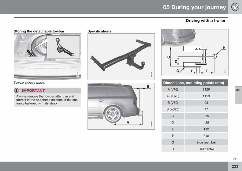
05 During your journey
Driving with a trailer
05
��
233
Storing the detachable towbar
G03
1121
Towbar storage space.
IMPORTANT
Always remove the towbar after use andstore it in the appointed location in the car,firmly fastened with its strap.
Specifications
G02
1485
B
A
G02
6080
F
H
EG
CD
G01
7971
Dimensions, mounting points (mm)
A (V70) 1129
A (XC70) 1113
B (V70) 93
B (XC70) 77
C 855
D 428
E 112
F 346
G Side member
H Ball centre
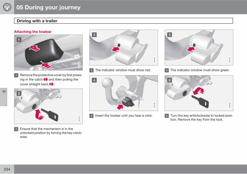
05 During your journey
Driving with a trailer
05
234
Attaching the towbar
G01
8928
Remove the protective cover by first press-ing in the catch and then pulling thecover straight back .
G02
1487
Ensure that the mechanism is in theunlocked position by turning the key clock-wise.
G02
1488
The indicator window must show red.
G02
1489
Insert the towbar until you hear a click.
G02
1490
The indicator window must show green.
G00
0000
Turn the key anticlockwise to locked posi-tion. Remove the key from the lock.

05 During your journey
Driving with a trailer
05
��
235
G02
1494
Check that the towbar is secure by pullingit up, down and back.
WARNING
If the towbar is not fitted correctly then itmust be detached and reattached inaccordance with the previous instructions.
IMPORTANT
Only grease in the ball for the towing hitch,the remainder of the towbar should be cleanand dry.
G02
1495
Safety cable.
WARNING
Be sure to attach the trailer's safety cable tothe correct place.
Removing the towbar
Insert the key and turn it clockwise to theunlocked position.
Push in the locking wheel and turn itanticlockwise until you hear a click.
Turn the locking wheel down fully, until itcomes to a stop. Hold it in this positionwhile pulling the towbar rearward andupward.
WARNING
Secure the towbar safely if it is stored in thecar, see page 233.

05 During your journey
Driving with a trailer
05
236
G01
8929
Push the protective cover until it snapstight.
05 During your journey
Towing and recovery
05
��
237
Towing
Find out the highest legal speed for towingbefore towing the car.
1. Press the remote control key into the igni-tion switch to unlock the steering lock sothat the car can be steered, see page 74.
2. The remote control key must remain in theignition switch while the car is being towed.
3. Keep the towline taut when the towingvehicle reduces speed by holding your footgently pressed on the brake pedal -thereby avoiding unnecessary jerking.
4. Be prepared to brake to stop.
WARNING
• The steering lock must be unlockedbefore towing.
• The remote control key must be in keyposition II.
• Never remove the remote control keyfrom the ignition switch while driving orwhen the car is being towed.
WARNING
The brake servo and power steering do notwork when the engine is switched off. Thebrake pedal must be pressed about fivetimes harder than normal, and the steeringwill be considerably heavier than normal.
Manual gearbox
� Move gear lever into neutral and releasethe parking brake.
Automatic gearbox, Geartronic
IMPORTANT
Note that the car must always be towed withthe wheels rolling forward.
• Cars with automatic gearbox must notbe towed at speeds above 80 km/h orfurther than 80 km.
� Move the gear selector to position N andrelease the parking brake.
Automatic gearbox, Powershift
The 2.0, 2.0T and 2.0F models with Powershiftautomatic transmission should not be towedas the transmission is dependent on the enginerunning in order to receive sufficient lubrica-tion.
IMPORTANT
Avoid towing.
• However, the car can be towed for ashort distance at low speed to move itfrom a dangerous position - not furtherthan 10 km and not faster than10 km/h. Note that the car must alwaysbe towed with the wheels rolling for-ward.
• In the event of moving a longer distancethan 10 km, the car must be transportedwith the drive wheels raised from theroad - professional recovery is recom-mended.
� Move the gear selector to position N andrelease the parking brake.
Jump starting
Do not tow the car to bump start the engine.Use a donor battery if the battery is dischargedand the engine does not start, see page 111.
IMPORTANT
Bump starting the car can damage the cat-alytic converter.
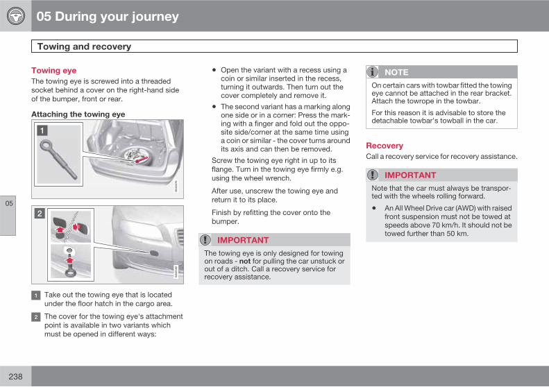
05 During your journey
Towing and recovery
05
238
Towing eye
The towing eye is screwed into a threadedsocket behind a cover on the right-hand sideof the bumper, front or rear.
Attaching the towing eye
Take out the towing eye that is locatedunder the floor hatch in the cargo area.
The cover for the towing eye's attachmentpoint is available in two variants whichmust be opened in different ways:
• Open the variant with a recess using acoin or similar inserted in the recess,turning it outwards. Then turn out thecover completely and remove it.
• The second variant has a marking alongone side or in a corner: Press the mark-ing with a finger and fold out the oppo-site side/corner at the same time usinga coin or similar - the cover turns aroundits axis and can then be removed.
Screw the towing eye right in up to itsflange. Turn in the towing eye firmly e.g.using the wheel wrench.
After use, unscrew the towing eye andreturn it to its place.
Finish by refitting the cover onto thebumper.
IMPORTANT
The towing eye is only designed for towingon roads - not for pulling the car unstuck orout of a ditch. Call a recovery service forrecovery assistance.
NOTE
On certain cars with towbar fitted the towingeye cannot be attached in the rear bracket.Attach the towrope in the towbar.
For this reason it is advisable to store thedetachable towbar's towball in the car.
Recovery
Call a recovery service for recovery assistance.
IMPORTANT
Note that the car must always be transpor-ted with the wheels rolling forward.
• An All Wheel Drive car (AWD) with raisedfront suspension must not be towed atspeeds above 70 km/h. It should not betowed further than 50 km.

05 During your journey
05
239

240 * Option/accessory, for more information, see Introduction.
General ................................................................................................. 242Changing wheels .................................................................................. 246Tyre pressure ....................................................................................... 248Warning triangle and first-aid kit*.......................................................... 249Emergency puncture repair (TMK)* ...................................................... 250
WHEELS AND TYRES

06 Wheels and tyres
General
06
242
Driving characteristics
Tyres greatly affect the car's driving characte-ristics. The type of tyre, dimensions, tyre pres-sure and speed rating are important for how thecar performs.
Direction of rotation
G02
1778
The arrow shows the tyre's direction of rotation.
Tyres with a tread pattern which are designedto only turn in one direction have the directionof rotation marked with an arrow. The tyre mustalways rotate in the same direction throughoutits lifespan. Tyres should only be switchedbetween front and rear positions, neverbetween left and right-hand sides, or viceversa. If the tyres are fitted incorrectly, the car'sbraking characteristics and capacity to forcerain and slush out of the way are adverselyaffected.
Tyres with the greatest tread depth shouldalways be fitted to the rear of the car (todecrease the risk of skidding).
NOTE
Ensure that tyres of the same type anddimensions, and also the same make, arefitted to all four wheels.
Follow the recommended tyre pressuresspecified in the tyre pressure table, seepage 310.
Tyre care
Tyre age
All tyres older than 6 years old should bechecked by an expert even if they seemundamaged. Tyres age and decompose, evenif they are hardly ever or never used. The func-tion can therefore be affected. This applies toall tyres that are stored for future use. Exam-ples of external signs which indicate that thetyre is unsuitable for use are cracks or discol-oration.
New tyres
Tyres are perishable. After a few years theybegin to harden at the same time as the frictioncapacity/characteristics gradually deteriorate.For this reason, aim to get as fresh tyres aspossible when you replace them. This is espe-cially important with regard to winter tyres. Thelast four digits in the sequence mean the weekand year of manufacture. This is the tyre'sDOT marking (Department of Transportation),and this is stated with four digits, for example1510. The tyre in the illustration was manufac-tured in week 15 of 2010.
Summer and winter tyres
When summer and winter wheels are changedthe wheels should be marked with which sideof the car they were mounted on, for exampleL for left and R for right.

06 Wheels and tyres
General
06
��
* Option/accessory, for more information, see Introduction. 243
Wear and maintenance
The correct tyre pressure results in more evenwear, see page 248. Driving style, tyre pres-sure, climate and road condition affect howquickly your tyres age and wear. To avoid dif-ferences in tread depth and to prevent wearpatterns arising, the front and rear wheels canbe switched with each other. A suitable dis-tance for the first change is approx. 5000 kmand then at 10 000 km intervals. Volvo recom-mends that you contact an authorised Volvoworkshop for checking if you are uncertainabout tread depth. If significant differences inwear (>1 mm difference in tread depth)between tyres have already occurred, the leastworn tyres must always be placed on the rear.Understeer is normally easier to correct thanoversteer, and leads to the car continuing for-wards in a straight line rather than having therear end skidding to one side, resulting in pos-sible complete loss of control over the car. Thisis why it is important for the rear wheels neverto lose grip before the front wheels.
Wheels should be stored lying down or hangingup - and not standing up.
WARNING
A damaged tyre can lead to loss of controlof the car.
Tyres with tread wear indicators
G02
1829
Tread wear indicators.
Tread wear indicators are narrow treadlessbands across the width of the tread. On theside of the tyre are the letters TWI (Tread WearIndicator). When the tyre's tread depth is downto 1.6 mm, the tread depth will be level in heightwith the tread wear indicators. Change to newtyres as soon as possible. Remember thattyres with little tread depth provide very poorgrip in rain and snow.
Rims and wheel bolts
IMPORTANT
The wheel bolts must be tightened to140 Nm. Overtightening can damage thenuts and the bolts.
Only use rims that are tested and approved byVolvo and which are Volvo genuine accesso-ries. Check the torque with a torque wrench.
Locking wheel bolts*
Locking wheel bolts* can be used on both alu-minium and steel rims. Under the cargo areafloor there is space for the sleeve for the lock-able wheel bolts.
Tools
Located under the cargo area floor are thecar's towing eye, jack* and wheel wrench*.There is also space for the sleeve for the lock-able wheel bolts.
Jack*
The jack's thread must always be well greased.

06 Wheels and tyres
General
06
244 * Option/accessory, for more information, see Introduction.
The original jack should only be used forchanging to the spare wheel. The jack's threadmust always be well greased.
Tools - returning into place
G02
9336
The tools and jack* must be returned to theircorrect places after use. The jack needs to becranked together to the correct position inorder to have space.
The foam block and spare wheel are replacedin the reverse order to taking out.
Note that there is an arrow on the upper foamblock. It must point forwards in the car.
IMPORTANT
The tools and jack* must be stored in theintended location in the car's cargo areawhen not in use.
NOTE
If the floor hatch in the cargo area floor is notclosed then privacy locking does not work,see page 49.
Winter tyres
Volvo recommends winter tyres with particulardimensions. Tyre dimensions are dependenton engine variant. When driving on winter tyres,the correct type of tyres must be fitted to allfour wheels.
NOTE
Volvo recommends that you consult a Volvodealer about which wheel rim and tyre typesare most suitable.
Studded tyres
Studded winter tyres should be run in gently for500-1000 km so the studs settle properly intothe tyres. This gives the tyre, and especially thestuds, a longer service life.
NOTE
The legal provisions for the use of studdedtyres vary from country to country.
Tread depth
Road conditions with ice, slush and low tem-peratures place considerably higher demandson tyres than summer conditions. Volvo there-fore recommends not to drive on winter tyresthat have a tread depth of less than 4 millime-tres.
Using snow chains
Snow chains may only be used on the frontwheels (also applies to all-wheel drive cars).
Never drive faster than 50 km/h with snowchains. Avoid driving on bare ground as thiswears out both the snow chains and tyres.
WARNING
Use Volvo genuine snow chains or equiva-lent chains designed for the car model, andtyre and rim dimensions. In the event ofuncertainty Volvo recommends that youconsult an authorised Volvo workshop. Thewrong snow chains may cause seriousdamage to your car and lead to an accident.

06 Wheels and tyres
General
06
245
Specifications
The car has whole vehicle approval. Thismeans that certain combinations of wheels andtyres are approved. For the permissible com-binations, see page 308
Wheel (rim) dimensions
Wheels (rims) have a designation of dimen-sions, for example: 7Jx16x50.
7 Rim width in inches
J Rim flange profile
16 Rim diameter ininches
50 Off-set in mm (dis-tance from wheelcentre to wheel con-tact surface againstthe hub)
Tyre dimensions
225/50R17 98W.
The dimensions are stated on all car tyres.Example of designation:
225 Tyre width (mm)
50 Ratio between tyre wall height andtyre width (%)
R Radial ply
17 Rim diameter in inches (")
98 Codes for the maximum permittedtyre load, tyre load index (LI)
W Speed rating for maximum permittedspeed, speed rating (SS). (In this case270 km/h).
Load index
Each tyre has a certain capacity to carry a load,a load index (LI). The car's weight determinesthe load capacity required of the tyres. Mini-mum permitted index is specified in the table,see page 308.
Speed ratings
Each tyre can withstand a certain maximumspeed, a speed rating (Speed Symbol; SS).
Tyre speed class must at least correspond withthe car's top speed. Minimum permitted speedrating is specified in the table, see page 308.
The only exception to these conditions is win-ter tyres (both those with metal studs and thosewithout), where a lower speed rating may beused. If such a tyre is chosen, the car must notbe driven faster than the speed rating of thetyre (for example, class Q can be driven at amaximum of 160 km/h).
Traffic regulations determine how fast a carcan be driven, not the speed rating of the tyres.
NOTE
It is the maximum permitted speed that isstated in the table.
Q 160 km/h (used only on winter tyres)
T 190 km/h
H 210 km/h
V 240 km/h
W 270 km/h
Y 300 km/h
WARNING
The car must be fitted with tyres which havethe same or a higher load index (LI) andspeed rating (SS) than specified. If a tyrewith too low a load index or speed rating isused, it may overheat.
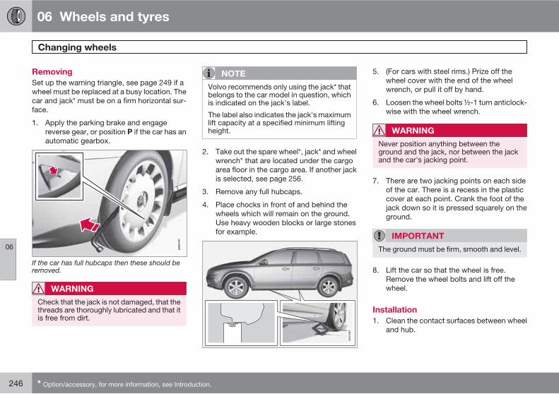
06 Wheels and tyres
Changing wheels
06
246 * Option/accessory, for more information, see Introduction.
Removing
Set up the warning triangle, see page 249 if awheel must be replaced at a busy location. Thecar and jack* must be on a firm horizontal sur-face.
1. Apply the parking brake and engagereverse gear, or position P if the car has anautomatic gearbox.
If the car has full hubcaps then these should beremoved.
WARNING
Check that the jack is not damaged, that thethreads are thoroughly lubricated and that itis free from dirt.
NOTE
Volvo recommends only using the jack* thatbelongs to the car model in question, whichis indicated on the jack's label.
The label also indicates the jack's maximumlift capacity at a specified minimum liftingheight.
2. Take out the spare wheel*, jack* and wheelwrench* that are located under the cargoarea floor in the cargo area. If another jackis selected, see page 256.
3. Remove any full hubcaps.
4. Place chocks in front of and behind thewheels which will remain on the ground.Use heavy wooden blocks or large stonesfor example.
5. (For cars with steel rims.) Prize off thewheel cover with the end of the wheelwrench, or pull it off by hand.
6. Loosen the wheel bolts ½-1 turn anticlock-wise with the wheel wrench.
WARNING
Never position anything between theground and the jack, nor between the jackand the car's jacking point.
7. There are two jacking points on each sideof the car. There is a recess in the plasticcover at each point. Crank the foot of thejack down so it is pressed squarely on theground.
IMPORTANT
The ground must be firm, smooth and level.
8. Lift the car so that the wheel is free.Remove the wheel bolts and lift off thewheel.
Installation
1. Clean the contact surfaces between wheeland hub.
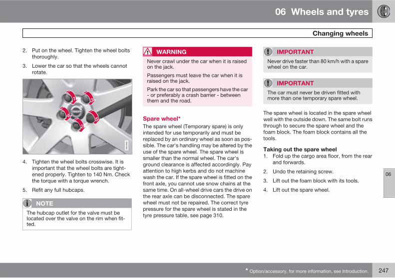
06 Wheels and tyres
Changing wheels
06
* Option/accessory, for more information, see Introduction. 247
2. Put on the wheel. Tighten the wheel boltsthoroughly.
3. Lower the car so that the wheels cannotrotate.
4. Tighten the wheel bolts crosswise. It isimportant that the wheel bolts are tight-ened properly. Tighten to 140 Nm. Checkthe torque with a torque wrench.
5. Refit any full hubcaps.
NOTE
The hubcap outlet for the valve must belocated over the valve on the rim when fit-ted.
WARNING
Never crawl under the car when it is raisedon the jack.
Passengers must leave the car when it israised on the jack.
Park the car so that passengers have the car- or preferably a crash barrier - betweenthem and the road.
Spare wheel*
The spare wheel (Temporary spare) is onlyintended for use temporarily and must bereplaced by an ordinary wheel as soon as pos-sible. The car's handling may be altered by theuse of the spare wheel. The spare wheel issmaller than the normal wheel. The car'sground clearance is affected accordingly. Payattention to high kerbs and do not machinewash the car. If the spare wheel is fitted on thefront axle, you cannot use snow chains at thesame time. On all-wheel drive cars the drive onthe rear axle can be disconnected. The sparewheel must not be repaired. The correct tyrepressure for the spare wheel is stated in thetyre pressure table, see page 310.
IMPORTANT
Never drive faster than 80 km/h with a sparewheel on the car.
IMPORTANT
The car must never be driven fitted withmore than one temporary spare wheel.
The spare wheel is located in the spare wheelwell with the outside down. The same bolt runsthrough to secure the spare wheel and thefoam block. The foam block contains all thetools.
Taking out the spare wheel
1. Fold up the cargo area floor, from the rearand forwards.
2. Undo the retaining screw.
3. Lift out the foam block with its tools.
4. Lift out the spare wheel.

06 Wheels and tyres
Tyre pressure
06
248
Tyre pressure
G02
1830
The tyre pressure decal on the driver's sidedoor pillar (between frame and rear door)shows which pressures the tyres should haveat different loads and speed conditions. This isalso specified in the tyre pressure table, seepage 310.
• Tyre pressure for the car's recommendedtyre dimension
• ECO pressure1
• Spare wheel tyre pressure (TemporarySpare)
NOTE
Temperature differences change thetyre pressure.
Fuel economy, ECO pressure
At speeds under 160 km/h, the general tyrepressure is recommended (applies for both fullload and light load) in order to obtain optimumfuel economy.
Checking the tyre pressure
The tyre pressures must be checked everymonth.
This also applies to the car's spare wheel.
Check tyre pressures on cold tyres. "Coldtyres" means the tyres are the same tempera-ture as the ambient temperature. After severalkilometres of driving, the tyres warm up and thepressure increases.
Inadequate tyre pressure increases fuel con-sumption, shortens tyre lifespan and impairsthe car's roadholding. Driving on tyres with tyrepressure that is too low could result in the tyresoverheating and being damaged. Tyre pres-sure affects travelling comfort, road noise andsteering characteristics.
NOTE
Tyre pressure decreases over time, this is anatural phenomenon. Tyre pressure alsovaries depending on ambient temperature.
1 ECO pressure results in improved fuel economy.
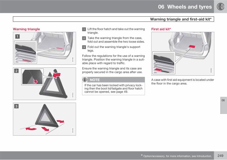
06 Wheels and tyres
Warning triangle and first-aid kit*
06
* Option/accessory, for more information, see Introduction. 249
Warning triangle Lift the floor hatch and take out the warningtriangle.
Take the warning triangle from the case,fold out and assemble the two loose sides.
Fold out the warning triangle's supportlegs.
Follow the regulations for the use of a warningtriangle. Position the warning triangle in a suit-able place with regard to traffic.
Ensure the warning triangle and its case areproperly secured in the cargo area after use.
NOTE
If the car has been locked with privacy lock-ing then the boot lid/tailgate and floor hatchcannot be opened, see page 49.
First aid kit*
G01
8253
A case with first aid equipment is located underthe floor in the cargo area.
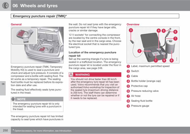
06 Wheels and tyres
Emergency puncture repair (TMK)*
06
250 * Option/accessory, for more information, see Introduction.
General
Emergency puncture repair (TMK; TemporaryMobility Kit) is used to seal a puncture andcheck and adjust tyre pressure. It consists of acompressor and a bottle with sealing fluid. Thekit works as a temporary repair. The sealingfluid bottle must be replaced before its expira-tion date and after use.
The sealing fluid effectively seals tyres punc-tured in the tread.
NOTE
The emergency puncture repair kit is onlyintended for sealing tyres with a puncture inthe tread.
The emergency puncture repair kit has limitedcapacity to seal tyres which have punctures in
the wall. Do not seal tyres with the emergencypuncture repair kit if they have larger slits,cracks or similar damage.
12 V sockets* for connecting the compressorare located by the centre console in the front,by the rear seat and in the cargo area. Choosethe electrical socket that is nearest the punc-tured tyre.
Location of the emergency puncture
repair kit
Set up the warning triangle if a tyre is beingsealed in a trafficked location. The emergencypuncture repair kit is located under the floor inthe cargo area, see page 249.
WARNING
You should not drive faster than 80 km/hafter the emergency tyre repair kit has beenused. Volvo recommends that you visit anauthorised Volvo workshop for inspection ofthe sealed tyre (maximum driving distanceis 200 km). The staff there can determinewhether or not the tyre can be repaired or ifit needs to be replaced.
Overview
Label, maximum permitted speed
Switch
Cable
Bottle holder (orange cap)
Protective cap
Pressure reducing valve
Air hose
Sealing fluid bottle
Pressure gauge

06 Wheels and tyres
Emergency puncture repair (TMK)*
06
��
* Option/accessory, for more information, see Introduction. 251
Sealing punctured tyres
G01
4338
For information on the function of the parts, seepreceding illustration.
1. Open the lid of the emergency puncturerepair kit.
2. Detach the label for maximum permittedspeed and affix it to the steering wheel.
WARNING
The sealing fluid can irritate the skin. In thecase of contact with skin, wash away thefluid with soap and water.
3. Check that the switch is in position 0 andlocate the cable and the air hose.
NOTE
Do not break the bottle's seal before use.The seal is broken automatically when thebottle is screwed in.
4. Unscrew the orange cap and unscrew thebottle's stopper.
5. Screw the bottle into its holder.
WARNING
Do not unscrew the bottle, it is equippedwith a reverse catch to prevent leakage.
6. Unscrew the wheel's dust cap and screwin the air hose valve connection to the bot-tom of the thread on the tyre's air valve.
7. Plug the cable into the 12 V socket andstart the car.
WARNING
Do not leave children in the car withoutsupervision when the engine is running.
8. Flick the switch to position I.
WARNING
Never stand next to the tyre when the com-pressor is running. If cracks or unevennessarise then the compressor must beswitched off immediately. The journeyshould not be continued. Contacting anauthorised tyre centre is recommended.
NOTE
When the compressor starts, the pressurecan increase up to 6 bar but the pressuredrops after approximately 30 seconds.
9. Inflate the tyre for 7 minutes.
IMPORTANT
Risk of overheating. The compressor mustnot run for more than 10 minutes.
10. Switch off the compressor to check thepressure on the pressure gauge. Minimum
06 Wheels and tyres
Emergency puncture repair (TMK)*
06
252 * Option/accessory, for more information, see Introduction.
pressure is 1.8 bar and maximum 3.5 bar.(Release air with the pressure reducingvalve if the tyre pressure is too high.)
WARNING
If the pressure is below 1.8 bar then the holein the tyre is too big. The journey should notbe continued. Contacting an authorised tyrecentre is recommended.
11. Switch off the compressor and unplug thecable from the 12 V socket.
12. Detach the hose from the tyre valve and fitthe valve cap.
13. As soon as possible, drive approximately3 km at a maximum speed of 80 km/h sothat the sealing fluid can seal the tyre.
Rechecking the repair and pressure
1. Reconnect the equipment.
2. Read the tyre pressure on the pressuregauge.
• If it is below 1.3 bar then the tyre isinsufficiently sealed. The journey shouldnot be continued. Contact a tyre centre.
• If the tyre pressure is higher than 1.3bar, the tyre must be inflated to the pres-sure specified in accordance with the
tyre pressure table, see page 310 (1bar=100 kPa). Release air using thepressure reducing valve if the tyre pres-sure is too high.
WARNING
Do not unscrew the bottle, it is equippedwith a reverse catch to prevent leakage.
3. Make sure the compressor is switched off.Detach the air hose and cable. Refit thedust cap.
NOTE
The sealing fluid bottle and the hose mustbe replaced after use. Volvo recommendsthat this replacement is performed by anauthorised Volvo workshop.
WARNING
Check the tyre pressure regularly.
Volvo recommends that you drive to the near-est authorised Volvo workshop for the replace-ment/repair of the damaged tyre. Advise theworkshop that the tyre contains sealing fluid.
WARNING
You should not drive faster than 80 km/hafter the emergency tyre repair kit has beenused. Volvo recommends that you visit anauthorised Volvo workshop for inspection ofthe sealed tyre (maximum driving distanceis 200 km). The staff there can determinewhether or not the tyre can be repaired or ifit needs to be replaced.
Inflating the tyres
The car's original tyres can be inflated by thecompressor.
1. The compressor must be switched off.Make sure that the switch is in position 0and locate the cable and air hose.
2. Unscrew the wheel's dust cap and screwin the air hose valve connection to the bot-tom of the thread on the tyre's air valve.
WARNING
Inhaling car exhaust fumes can result indanger to life. Never leave the engine run-ning in sealed areas or areas that lack suf-ficient ventilation.

06 Wheels and tyres
Emergency puncture repair (TMK)*
06
* Option/accessory, for more information, see Introduction. 253
WARNING
Do not leave children in the car withoutsupervision when the engine is running.
3. Connect the cable to one of the car's 12 Vsockets and start the car.
4. Start the compressor by flicking the switchto position I.
IMPORTANT
Risk of overheating. The compressor mustnot run for more than 10 minutes.
5. Inflate the tyre to the pressure specified inaccordance with the tyre pressure table,see page 310. (Release air using the pres-sure reducing valve if the tyre pressure istoo high.)
6. Detach the air hose and cable.
7. Refit the dust cap.
Replacing the sealing fluid canister
Replace the bottle when the expiration datehas passed. Treat the old bottle as environ-mentally hazardous waste.
WARNING
The bottle contains 1.2-Ethanol and naturalrubber-latex.
Harmful if ingested. Could result in allergicreaction in the event of skin contact.
Avoid contact with the skin and eyes.
Store out of the reach of children.

254
Engine compartment............................................................................. 256Lamps................................................................................................... 263Wiper blades and washer fluid.............................................................. 269Battery................................................................................................... 271Fuses..................................................................................................... 274Car care................................................................................................ 282

MAINTENANCE AND SERVICE
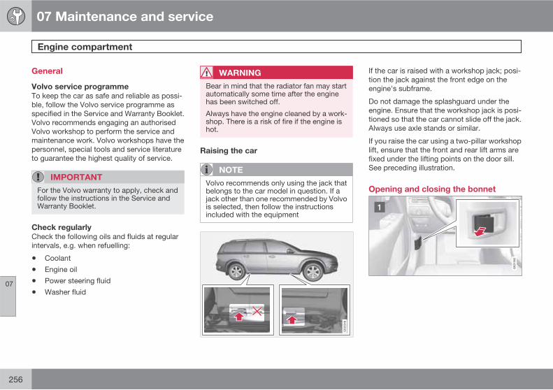
07 Maintenance and service
Engine compartment
07
256
General
Volvo service programme
To keep the car as safe and reliable as possi-ble, follow the Volvo service programme asspecified in the Service and Warranty Booklet.Volvo recommends engaging an authorisedVolvo workshop to perform the service andmaintenance work. Volvo workshops have thepersonnel, special tools and service literatureto guarantee the highest quality of service.
IMPORTANT
For the Volvo warranty to apply, check andfollow the instructions in the Service andWarranty Booklet.
Check regularly
Check the following oils and fluids at regularintervals, e.g. when refuelling:
• Coolant
• Engine oil
• Power steering fluid
• Washer fluid
WARNING
Bear in mind that the radiator fan may startautomatically some time after the enginehas been switched off.
Always have the engine cleaned by a work-shop. There is a risk of fire if the engine ishot.
Raising the car
NOTE
Volvo recommends only using the jack thatbelongs to the car model in question. If ajack other than one recommended by Volvois selected, then follow the instructionsincluded with the equipment
If the car is raised with a workshop jack; posi-tion the jack against the front edge on theengine's subframe.
Do not damage the splashguard under theengine. Ensure that the workshop jack is posi-tioned so that the car cannot slide off the jack.Always use axle stands or similar.
If you raise the car using a two-pillar workshoplift, ensure that the front and rear lift arms arefixed under the lifting points on the door sill.See preceding illustration.
Opening and closing the bonnet
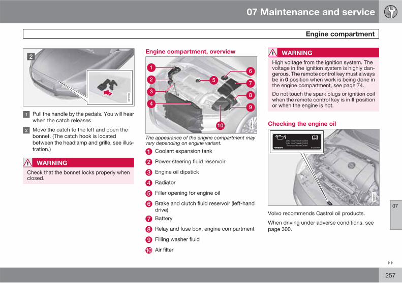
07 Maintenance and service
Engine compartment
07
��
257
G01
0951
Pull the handle by the pedals. You will hearwhen the catch releases.
Move the catch to the left and open thebonnet. (The catch hook is locatedbetween the headlamp and grille, see illus-tration.)
WARNING
Check that the bonnet locks properly whenclosed.
Engine compartment, overview
G01
8945
The appearance of the engine compartment mayvary depending on engine variant.
Coolant expansion tank
Power steering fluid reservoir
Engine oil dipstick
Radiator
Filler opening for engine oil
Brake and clutch fluid reservoir (left-handdrive)
Battery
Relay and fuse box, engine compartment
Filling washer fluid
Air filter
WARNING
High voltage from the ignition system. Thevoltage in the ignition system is highly dan-gerous. The remote control key must alwaysbe in 0 position when work is being done inthe engine compartment, see page 74.
Do not touch the spark plugs or ignition coilwhen the remote control key is in II positionor when the engine is hot.
Checking the engine oil
Volvo recommends Castrol oil products.
When driving under adverse conditions, seepage 300.
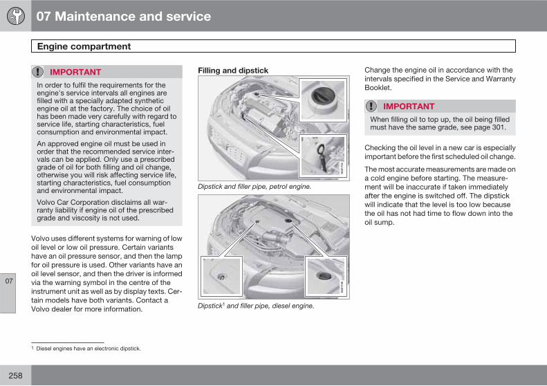
07 Maintenance and service
Engine compartment
07
258
IMPORTANT
In order to fulfil the requirements for theengine's service intervals all engines arefilled with a specially adapted syntheticengine oil at the factory. The choice of oilhas been made very carefully with regard toservice life, starting characteristics, fuelconsumption and environmental impact.
An approved engine oil must be used inorder that the recommended service inter-vals can be applied. Only use a prescribedgrade of oil for both filling and oil change,otherwise you will risk affecting service life,starting characteristics, fuel consumptionand environmental impact.
Volvo Car Corporation disclaims all war-ranty liability if engine oil of the prescribedgrade and viscosity is not used.
Volvo uses different systems for warning of lowoil level or low oil pressure. Certain variantshave an oil pressure sensor, and then the lampfor oil pressure is used. Other variants have anoil level sensor, and then the driver is informedvia the warning symbol in the centre of theinstrument unit as well as by display texts. Cer-tain models have both variants. Contact aVolvo dealer for more information.
Filling and dipstick
G02
1734
Dipstick and filler pipe, petrol engine.
G02
1736
Dipstick1 and filler pipe, diesel engine.
Change the engine oil in accordance with theintervals specified in the Service and WarrantyBooklet.
IMPORTANT
When filling oil to top up, the oil being filledmust have the same grade, see page 301.
Checking the oil level in a new car is especiallyimportant before the first scheduled oil change.
The most accurate measurements are made ona cold engine before starting. The measure-ment will be inaccurate if taken immediatelyafter the engine is switched off. The dipstickwill indicate that the level is too low becausethe oil has not had time to flow down into theoil sump.
1 Diesel engines have an electronic dipstick.

07 Maintenance and service
Engine compartment
07
��
259
G02
1737
The oil level must be within the area marked on thedipstick.
Park the car on a level surface, switch off theengine and wait 10-15 minutes to allow the oiltime to run back to the sump. For capacities,see page 301 and onwards.
Checking with a cold engine
1. Wipe the dipstick clean.
2. Check the level using the dipstick. It mustbe between the MIN and MAX marks.
3. If the level is close to the MIN mark, startby topping up with 0.5 litres of oil. Top upuntil the level is nearer to MAX than MIN
on the dipstick.
IMPORTANT
Never fill above the MAX mark. Oil con-sumption may increase if too much oil ispoured into the engine.
WARNING
Do not spill oil onto the hot exhaust manifolddue to the risk of fire.
Checking with a warm engine
1. Park the car on a level surface, switch offthe engine and wait 10 - 15 minutes toallow the oil time to run back to the sump.
2. Wipe the dipstick clean.
3. Check the oil level using the dipstick.
4. If the level is close to the MIN mark, startby topping up with 0.5 litres of oil. Top upuntil the level is nearer to MAX than MIN
on the dipstick.
For engines with electronic dipstick2
The oil level is checked using the electronic oillevel gauge with the thumbwheel when theengine is switched off, see page 134.
Checking the oil level:
1. Switch the ignition to key position II, seepage 107.
2. Turn the thumbwheel to position Engine
oil level Wait....> The oil level in the engine is then shown.
NOTE
The oil level is only updated by the systemduring driving. The system cannot detectchanges when oil is filled or drained.
If engine oil is filled or drained then the carmust be driven about 30 km before the oillevel is measured correctly.
Message
Engine oil level OK All normal.
Engine oil level
Wait...
System initialised,shown forabout 2 seconds.
2 Only applies to diesel.

07 Maintenance and service
Engine compartment
07
260
Message
Engine oil level Fill
1 litre oil
Fill with engine oil
Engine oil level
Service required
Shown when thesystem hasdetected somethingthat needs to be rec-tified in order to ena-ble the correct infor-mation regarding oilvolume to be shown.
Coolant
Checking and topping up the coolant
When topping up the coolant, follow theinstructions on the packaging. It is importantthat the mixture of coolant concentrate andwater is correct for the prevailing weather con-ditions. Never top up with water only. The riskof freezing increases with both too little and toomuch coolant concentrate. For capacities, seepage 302.
IMPORTANT
• A high content of chlorine, chloridesand other salts may cause corrosion inthe cooling system.
• Always use coolant with anti-corrosionagent as recommended by Volvo.
• Ensure that the coolant mixture is 50%water and 50% coolant.
• Mix the coolant with approved qualitytap water. In the event of any doubtabout water quality, used ready-mixedcoolant in accordance with Volvo rec-ommendations.
• When changing coolant/replacing cool-ing system components, flush the cool-ing system clean with approved qualitytap water or flush with ready-mixedcoolant.
• The engine must only be run with a well-filled cooling system. High tempera-tures may occur, causing a risk of dam-age (cracks) to the cylinder head.
For capacities and for standards regardingwater quality, see page 302.
Check the coolant regularly
The level must lie between the MIN and MAX
marks on the expansion tank. If the system is

07 Maintenance and service
Engine compartment
07
��
261
not filled sufficiently, high temperatures couldoccur, causing a risk of damage to the engine.
WARNING
Coolant can be very hot. If the coolantrequires topping up when the engine is atoperating temperature, unscrew the expan-sion tank cap slowly to gently release theoverpressure.
Brake and clutch fluid
Checking the level
Brake and clutch fluid have a common reser-voir. The level must be between the MIN andMAX marks that are visible inside the reservoir.Check the level regularly.
Change the brake fluid every other year or atevery other regular service.
For capacities and recommended fluid grade,see page 302. The fluid should be changedannually on cars driven in conditions requiringhard, frequent braking, such as driving inmountains or tropical climates with highhumidity.
WARNING
If the brake fluid is under the MIN level in thebrake fluid reservoir, do not drive furtherbefore topping up the brake fluid. Volvo rec-ommends that the reason for the loss ofbrake fluid is investigated by an authorisedVolvo workshop.
Filling
The fluid reservoir is located on the driver's side.
The fluid reservoir is protected under the coverover the cold section in the engine compart-ment. The round cover must be removed firstbefore the reservoir cap can be reached.
1. Turn and open the cover located on thecovering.
2. Unscrew the reservoir cap and fill the fluid.The level must be between the MIN andMAX marks, which are located on theinside of the reservoir.
IMPORTANT
Do not forget to refit the cap.
Power steering fluid
IMPORTANT
Keep the area around the power steeringfluid reservoir clean when checking. Thecover must not be opened.
Check the level frequently. The fluid does notrequire changing. The fluid level must be
07 Maintenance and service
Engine compartment
07
262
between the MIN and MAX marks. For capaci-ties and recommended fluid grade, seepage 302.
NOTE
If a fault should arise in the power steeringsystem or if the engine is switched off andthe car must be towed, it can still be steered.

07 Maintenance and service
Lamps
07
��
263
General
For bulb specification, see page 268. Bulbsand spotlights that are of a special type or thatare only suitable for replacement by a work-shop are:
• General interior lighting in the roof, readinglamps
• Glovebox lighting
• Courtesy lighting
• Direction indicators, door mirror
• Approach lighting
• Brake light, fog lamp, reversing lamp
• Rear side position lamps, position lamps
• Xenon, Active Xenon lamps
• LED lamps, general
WARNING
On cars equipped with Xenon lamps, head-lamp replacement must be performed at aworkshop - an authorised Volvo workshopis recommended. The lamp must be han-dled with extreme caution because it isequipped with a high voltage unit.
IMPORTANT
Never touch the glass part of the bulbs withyour fingers. Grease and oils from your fin-gers are vaporised by the heat, coating thereflector and then causing damage.
Headlamps front
G010325
All of the headlamp bulbs are replaced via theengine compartment. Loosen and remove thewhole headlamp.
WARNING
Always switch off the ignition and removethe remote control key before starting toreplace a bulb.
Removing the headlamp
1. Press the START/STOP ENGINE buttonquickly.
2. (Upper illustration)
Pull out the headlamp's locking pins.
Pull the headlamp straight forward.
IMPORTANT
Do not pull the electrical cable, only the con-nector.
3. (Lower illustration)
Detach the headlamp connector bypressing down the clip with your thumb.
At the same time, guide out the con-nector with your other hand.
4. Lift out the headlamp and place it on a softsurface to avoid scratching the lens.
5. Replace the bulb in question, .
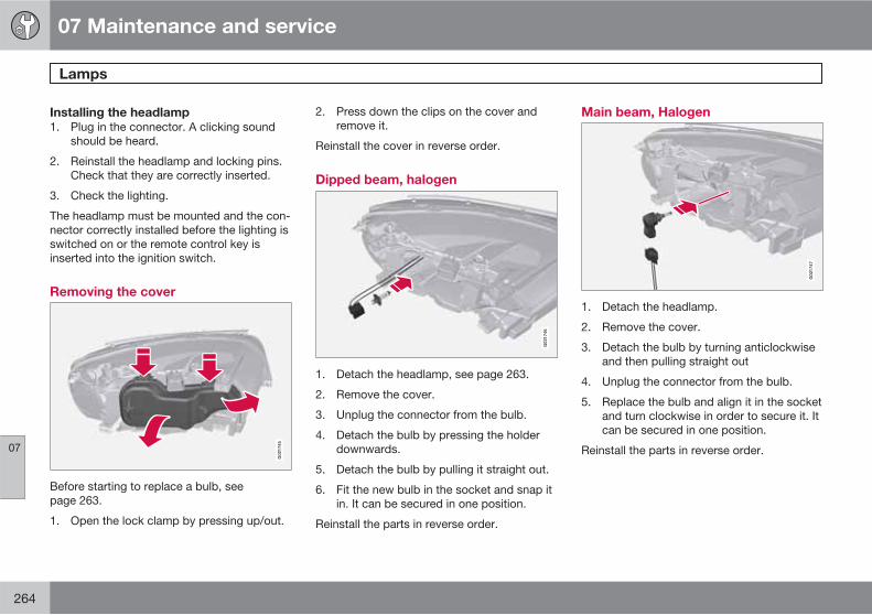
07 Maintenance and service
Lamps
07
264
Installing the headlamp
1. Plug in the connector. A clicking soundshould be heard.
2. Reinstall the headlamp and locking pins.Check that they are correctly inserted.
3. Check the lighting.
The headlamp must be mounted and the con-nector correctly installed before the lighting isswitched on or the remote control key isinserted into the ignition switch.
Removing the cover
G02
1745
Before starting to replace a bulb, seepage 263.
1. Open the lock clamp by pressing up/out.
2. Press down the clips on the cover andremove it.
Reinstall the cover in reverse order.
Dipped beam, halogen
G02
1746
1. Detach the headlamp, see page 263.
2. Remove the cover.
3. Unplug the connector from the bulb.
4. Detach the bulb by pressing the holderdownwards.
5. Detach the bulb by pulling it straight out.
6. Fit the new bulb in the socket and snap itin. It can be secured in one position.
Reinstall the parts in reverse order.
Main beam, Halogen
G02
1747
1. Detach the headlamp.
2. Remove the cover.
3. Detach the bulb by turning anticlockwiseand then pulling straight out
4. Unplug the connector from the bulb.
5. Replace the bulb and align it in the socketand turn clockwise in order to secure it. Itcan be secured in one position.
Reinstall the parts in reverse order.

07 Maintenance and service
Lamps
07
��
* Option/accessory, for more information, see Introduction. 265
Extra main beam, Xenon*
G02
1748
1. Detach the headlamp.
2. Remove the cover, see page 264.
3. Detach the bulb by pressing the holderdownwards.
4. Unplug the connector from the bulb.
5. Fit the new bulb in the socket and snap itin. It can only be secured in one position.
Reinstall the parts in reverse order.
Position/parking lamps
G02
1749
1. Detach the headlamp.
2. Remove the cover, see page 264.
3. For better access, detach the main beambulb first.
4. Pull the cable in order to withdraw the bulbholder.
5. Remove the blown bulb and fit a new one.It can only be secured in one position.
6. Fit the bulb holder in the socket and pressuntil a clicking sound is heard.
Reinstall the parts in reverse order.
Direction indicators/flashers
G02
1750
1. Detach the headlamp.
2. Remove the small round cover.
3. Pull the bulb holder in order to extract thebulb.
4. Remove the blown bulb and fit a new one.It can only be installed in one way.
5. Fit the bulb holder in the socket and pressuntil a clicking sound is heard.
6. Refit the cover. It must be fitted andpressed in until a clicking sound is heard.
Reinstall the parts in reverse order.
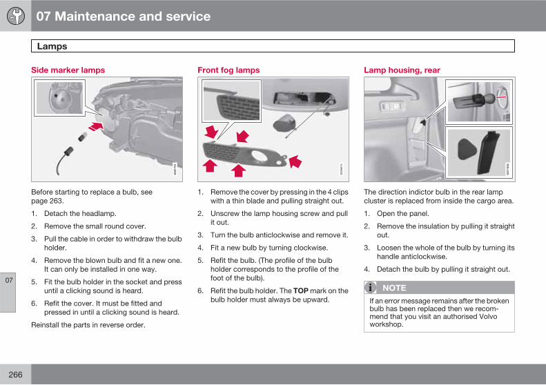
07 Maintenance and service
Lamps
07
266
Side marker lamps
G02
1751
Before starting to replace a bulb, seepage 263.
1. Detach the headlamp.
2. Remove the small round cover.
3. Pull the cable in order to withdraw the bulbholder.
4. Remove the blown bulb and fit a new one.It can only be installed in one way.
5. Fit the bulb holder in the socket and pressuntil a clicking sound is heard.
6. Refit the cover. It must be fitted andpressed in until a clicking sound is heard.
Reinstall the parts in reverse order.
Front fog lamps
1. Remove the cover by pressing in the 4 clipswith a thin blade and pulling straight out.
2. Unscrew the lamp housing screw and pullit out.
3. Turn the bulb anticlockwise and remove it.
4. Fit a new bulb by turning clockwise.
5. Refit the bulb. (The profile of the bulbholder corresponds to the profile of thefoot of the bulb).
6. Refit the bulb holder. The TOP mark on thebulb holder must always be upward.
Lamp housing, rear
G01
7456
The direction indictor bulb in the rear lampcluster is replaced from inside the cargo area.
1. Open the panel.
2. Remove the insulation by pulling it straightout.
3. Loosen the whole of the bulb by turning itshandle anticlockwise.
4. Detach the bulb by pulling it straight out.
NOTE
If an error message remains after the brokenbulb has been replaced then we recom-mend that you visit an authorised Volvoworkshop.

07 Maintenance and service
Lamps
07
��
267
Location of rear bulbs
G01
7457
Lamp lens, right-hand side
Position lamps/brake light (LED)
Side position lights, SML (LED)
Direction indicators
Reflector, rear
Rear fog lamp (one side)
Reversing lamp
Brake light (LED)
Brake light (LED)
Number plate lighting
G01
7458
1. Remove the screws with a screwdriver.
2. Carefully detach the whole lamp housingand withdraw it.
3. Replace the bulb.
4. Refit the whole lamp housing and screw itinto place.
Lighting, cargo area
G03
1942
1. Insert a screwdriver and gently prize sothat the lamp housing comes loose.
2. Replace the bulb.
3. Check that the bulb illuminates and pressback the lamp housing.

07 Maintenance and service
Lamps
07
268
Vanity mirror lighting
Removing the mirror glass
G02
1759
1. Insert a screwdriver underneath the loweredge, in the centre. Carefully prize up thelug on the edge.
2. Insert the screwdriver underneath the edgeon the left and right-hand sides (by theblack rubber sections), and prize carefullyso that the glass comes loose in the loweredge.
3. Carefully detach and lift aside the entiremirror glass and cover.
4. Replace the bulb.
Fitting the mirror glass
1. Press the three lugs at top edge of the mir-ror glass back into position.
2. Then press the three lower lugs back intoposition.
Specification, bulbs
Lighting W Type
Extra main beam,Xenon, ABL
55 H7
Dipped beam, hal-ogen
55 H7
Main beam, Halo-gen
65 H9
Front directionindicators
21 H21W
Direction indica-tors, rear
21 PY21W
Front fog lamps 35 H8
Cargo area light-ing, number platelighting
5 Tubularlamp
SV8.5
Vanity mirror 1.2 Tubularlamp
SV5.5
Lighting W Type
Front position andparking lamps
5 W5W
Front side markerlamps
5 W5W
Glovebox lighting 5 Tubularlamp
SV8.5
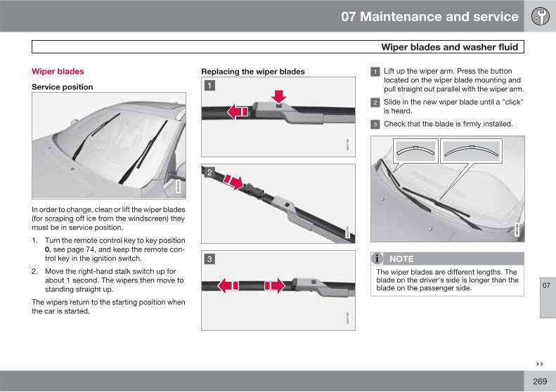
07 Maintenance and service
Wiper blades and washer fluid
07
��
269
Wiper blades
Service position
In order to change, clean or lift the wiper blades(for scraping off ice from the windscreen) theymust be in service position.
1. Turn the remote control key to key position0, see page 74, and keep the remote con-trol key in the ignition switch.
2. Move the right-hand stalk switch up forabout 1 second. The wipers then move tostanding straight up.
The wipers return to the starting position whenthe car is started.
Replacing the wiper blades Lift up the wiper arm. Press the buttonlocated on the wiper blade mounting andpull straight out parallel with the wiper arm.
Slide in the new wiper blade until a "click"is heard.
Check that the blade is firmly installed.
G02
1763
NOTE
The wiper blades are different lengths. Theblade on the driver's side is longer than theblade on the passenger side.

07 Maintenance and service
Wiper blades and washer fluid
07
270
Replacing the wiper blades, rear window
G03
2770
1. Fold out the wiper arm.
2. Grip the inner section of the blade (by thearrow).
3. Turn anticlockwise to use the blade's endposition against the wiper arm as a lever todetach the blade more easily.
4. Press the new wiper blade into position.Check that it is firmly installed.
5. Lower the wiper arm.
Cleaning
For cleaning wiper blades and windscreen, seepage 282 and onwards.
IMPORTANT
Check the wiper blades regularly.Neglected maintenance shortens the serv-ice life of the wiper blades.
Filling washer fluid
The windscreen and headlamp washers sharea common reservoir.
IMPORTANT
Add washer antifreeze during the winter sothat the fluid does not freeze in the pump,reservoir and hoses.
For capacities, see page 302.

07 Maintenance and service
Battery
07
��
271
Warning symbols on the battery
Use protective goggles.
Further information in theowner's manual.
Store the battery out ofthe reach of children.
The battery contains cor-rosive acid.
Avoid sparks and nakedflames.
Risk of explosion.
NOTE
An expended battery must be recycled in anenvironmentally responsible manner - itcontains lead.
Operation
• Check that the cables to the battery arecorrectly connected and properly tight-ened.
• Never disconnect the battery when theengine is running.
The service life and function of the battery isinfluenced by factors such as the number ofstarts, discharging, driving style, driving con-ditions, climatic conditions etc.
IMPORTANT
Never use a quick charger to charge thebattery.
WARNING
Batteries can generate oxyhydrogen gas,which is highly explosive. One spark, whichcan be generated if the jump leads are con-nected incorrectly, is sufficient to make thebattery explode. The battery contains sul-phuric acid, which can cause serious burns.If sulphuric acid comes into contact witheyes, skin or clothing, flush with large quan-tities of water. If acid splashes into the eyes,seek medical attention immediately.

07 Maintenance and service
Battery
07
272
NOTE
The life of the battery is shortened if itbecomes discharged repeatedly.
The life of the battery is affected by severalfactors, including driving conditions and cli-mate. Battery starting capacity decreasesgradually with time and therefore needs tobe recharged if the car is not used for alonger time or when it is only driven shortdistances. Extreme cold further limits star-ting capacity.
To maintain the battery in good condition, atleast 15 minutes of driving/week is recom-mended or that the battery is connected toa battery charger with automatic tricklecharging.
A battery that is kept fully charged has amaximum service life.
Changing
Removal
Switch off the ignition and wait for 5 minutes.
Open the clips on the front cover andremove the cover.
Release the rubber moulding so that therear cover is free.
Remove the rear cover by screwing onequarter turn and lifting it away.

07 Maintenance and service
Battery
07
273
WARNING
Connect and disconnect the positive andnegative cables in the correct sequence.
Detach the black negative cable
Detach the red positive cable
Detach the ventilation hose from the bat-tery
Loosen the screw holding the batteryclamp.
Move the battery to the side and lift it up.
Installation
1. Lower the battery into the battery box.
2. Move the battery inward and to the sideuntil it reaches the rear edge of the box.
3. Secure the battery using the battery clamp.
4. Connect the ventilation hose.
5. Connect the red positive cable.
6. Connect the black negative cable.
7. Press in the rear cover. (See Removal).
8. Reinstall the rubber moulding. (SeeRemoval).
9. Reinstall the front cover and secure it withthe clips. (See Removal).

07 Maintenance and service
Fuses
07
274
General
All electrical functions and components areprotected by a number of fuses in order to pro-tect the car's electrical system from damage byshort circuiting or overloading.
If an electrical component or function does notwork, it may be because the component's fusewas temporarily overloaded and failed. If thesame fuse fails repeatedly then there is a faultin the circuit. Volvo recommends that you visitan authorised Volvo workshop for checking.
Changing
1. Look in the fuse diagram to locate the fuse.
2. Pull out the fuse and check from the sideto see whether the curved wire has blown.
3. If this is the case, replace it with a new fuseof the same colour and amperage.
WARNING
Never use a foreign object, or a fuse with anamperage higher than that specified whenreplacing a fuse. This could cause signifi-cant damage to the electrical system andpossibly lead to fire.
Location, fuse boxes
Fuse box locations in a left-hand drive car. In aright-hand drive car the fuse box under the glo-vebox changes sides.
, Under the glovebox
Cargo area
Engine compartment

07 Maintenance and service
Fuses
07
��
275
Engine compartment
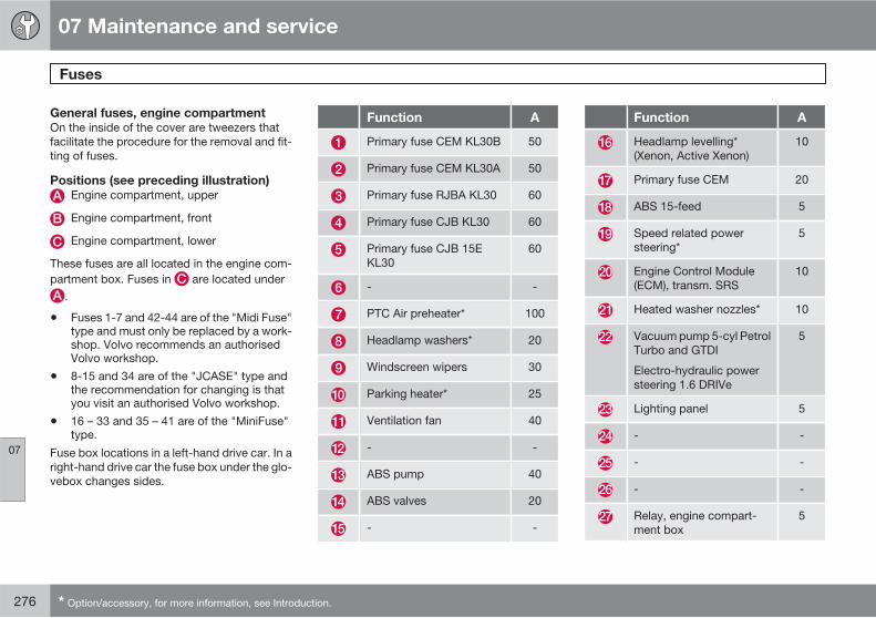
07 Maintenance and service
Fuses
07
276 * Option/accessory, for more information, see Introduction.
General fuses, engine compartment
On the inside of the cover are tweezers thatfacilitate the procedure for the removal and fit-ting of fuses.
Positions (see preceding illustration)
Engine compartment, upper
Engine compartment, front
Engine compartment, lower
These fuses are all located in the engine com-partment box. Fuses in are located under
.
• Fuses 1-7 and 42-44 are of the "Midi Fuse"type and must only be replaced by a work-shop. Volvo recommends an authorisedVolvo workshop.
• 8-15 and 34 are of the "JCASE" type andthe recommendation for changing is thatyou visit an authorised Volvo workshop.
• 16 – 33 and 35 – 41 are of the "MiniFuse"type.
Fuse box locations in a left-hand drive car. In aright-hand drive car the fuse box under the glo-vebox changes sides.
Function A
Primary fuse CEM KL30B 50
Primary fuse CEM KL30A 50
Primary fuse RJBA KL30 60
Primary fuse CJB KL30 60
Primary fuse CJB 15EKL30
60
- -
PTC Air preheater* 100
Headlamp washers* 20
Windscreen wipers 30
Parking heater* 25
Ventilation fan 40
- -
ABS pump 40
ABS valves 20
- -
Function A
Headlamp levelling*(Xenon, Active Xenon)
10
Primary fuse CEM 20
ABS 15-feed 5
Speed related powersteering*
5
Engine Control Module(ECM), transm. SRS
10
Heated washer nozzles* 10
Vacuum pump 5-cyl PetrolTurbo and GTDI
Electro-hydraulic powersteering 1.6 DRIVe
5
Lighting panel 5
- -
- -
- -
Relay, engine compart-ment box
5
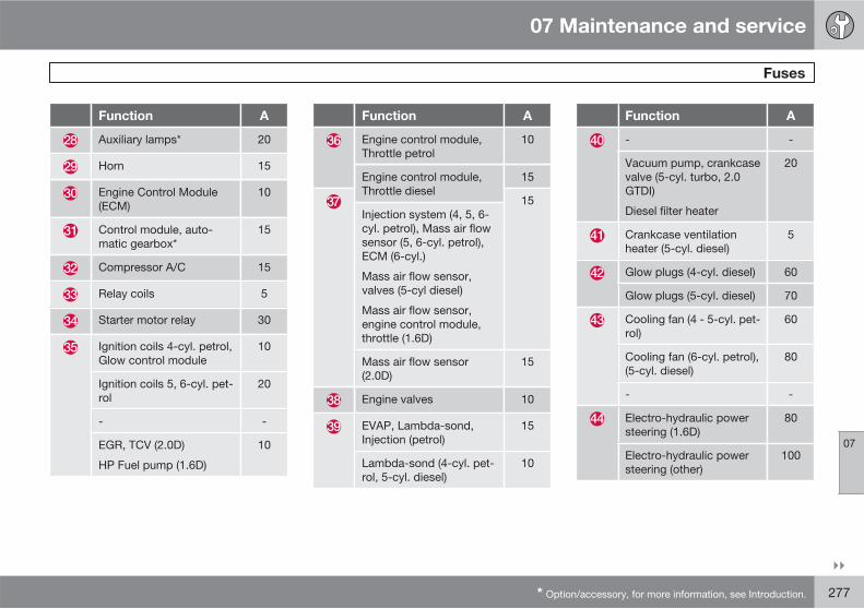
07 Maintenance and service
Fuses
07
��
* Option/accessory, for more information, see Introduction. 277
Function A
Auxiliary lamps* 20
Horn 15
Engine Control Module(ECM)
10
Control module, auto-matic gearbox*
15
Compressor A/C 15
Relay coils 5
Starter motor relay 30
Ignition coils 4-cyl. petrol,Glow control module
10
Ignition coils 5, 6-cyl. pet-rol
20
- -
EGR, TCV (2.0D)
HP Fuel pump (1.6D)
10
Function A
Engine control module,Throttle petrol
10
Engine control module,Throttle diesel
15
15Injection system (4, 5, 6-cyl. petrol), Mass air flowsensor (5, 6-cyl. petrol),ECM (6-cyl.)
Mass air flow sensor,valves (5-cyl diesel)
Mass air flow sensor,engine control module,throttle (1.6D)
Mass air flow sensor(2.0D)
15
Engine valves 10
EVAP, Lambda-sond,Injection (petrol)
15
Lambda-sond (4-cyl. pet-rol, 5-cyl. diesel)
10
Function A
- -
Vacuum pump, crankcasevalve (5-cyl. turbo, 2.0GTDI)
Diesel filter heater
20
Crankcase ventilationheater (5-cyl. diesel)
5
Glow plugs (4-cyl. diesel) 60
Glow plugs (5-cyl. diesel) 70
Cooling fan (4 - 5-cyl. pet-rol)
60
Cooling fan (6-cyl. petrol),(5-cyl. diesel)
80
- -
Electro-hydraulic powersteering (1.6D)
80
Electro-hydraulic powersteering (other)
100

07 Maintenance and service
Fuses
07
278 * Option/accessory, for more information, see Introduction.
Under the glovebox
Positions
BoxA
Function A
Primary fuse, controlmodule, audio
Bass speaker
40
- -
- -
- -
BoxA
Function A
- -
- -
12 V socket, cargo area 15
Control panel, driver'sdoor
20
Control panel, front pas-senger door
20
BoxA
Function A
Control panel, rear pas-senger door, right
20
Control panel, rear pas-senger door, left
20
Keyless* 20
Power seat driver's side* 20

07 Maintenance and service
Fuses
07
��
* Option/accessory, for more information, see Introduction. 279
BoxA
Function A
Power seat passengerside*
20
Folding head restraint* 15
- -
Radio, Display, RTI* 10
Infotainment system 15
Telephone, BluetoothTM* 5
- -
Sun roof*, interior lightingroof, climate sensor
5
Cigarette lighter
Rear Seat Entertainment(RSE)*
15
Seat heating (passengerside)
15
Seat heating (driver's side) 15
- -
BoxA
Function A
Seat heating, rear passen-ger side* right
15
Seat heating, rear passen-ger side* left
15
Parking assistance*
Parking camera*
RTI*
5
Control module AWD* 10
Active chassis Four-C* 10
BoxB
Function A
Rear wiper 15
- -
Interior lighting, Powerdriver's seat*
7,5
Information display (DIM) 5
BoxB
Function A
Adaptive cruise control,ACC*, collision warningsystem *
10
Interior lighting, Rain sen-sor
7,5
Steering wheel module 7,5
Central locking systemrear, fuel filler flap
10
Washers 15
Windscreen washers 15
Opening tailgate 10
Lock tailgate 10
Fuel pump 20
Remote control keyreceiver, Alarm*, Climate
5
Steering lock 15
Alarm/OBDII 5
- -

07 Maintenance and service
Fuses
07
280 * Option/accessory, for more information, see Introduction.
BoxB
Function A
Airbag 10
Collision warning system,radar front
5
Accelerator pedal, electricengine block heater (die-sel), power door mirrors*,seat heating, rear *
7,5
Infotainment (ICM), CD &RadioA
15
Brake light 5
Sun roof* 20
Immobiliser 5
A Not Premium or High Performance.
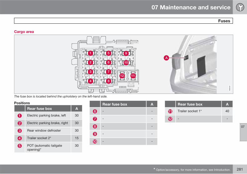
07 Maintenance and service
Fuses
07
* Option/accessory, for more information, see Introduction. 281
Cargo area
The fuse box is located behind the upholstery on the left-hand side.
Positions
Rear fuse box A
Electric parking brake, left 30
Electric parking brake, right 30
Rear window defroster 30
Trailer socket 2* 15
POT (automatic tailgateopening)*
30
Rear fuse box A
- -
- -
- -
- -
- -
Rear fuse box A
Trailer socket 1* 40
- -

07 Maintenance and service
Car care
07
282
Washing the car
Wash the car as soon as it becomes dirty.Wash the car in a car wash with oil separator.Use car shampoo.
• Remove bird droppings from the paintworkas soon as possible. Bird droppings con-tain chemicals that affect and discolourpaintwork very quickly. An authorisedVolvo workshop is recommended for theremoval of any discoloration.
• Hose down the underbody.
• Rinse the entire car to remove loose dirt.Do not spray directly onto the locks.
• Wash using a sponge, car shampoo andplenty of lukewarm water.
• Clean the wiper blades with a lukewarmsoap solution or car shampoo.
• Use cold degreasing agent on very dirtysurfaces.
• Dry the car using a clean, soft chamois ora water scraper.
WARNING
Always have the engine cleaned by a work-shop. There is a risk of fire if the engine ishot.
IMPORTANT
Dirty headlamps have impaired functional-ity. Clean them regularly, when refuelling forexample.
NOTE
Outside lighting such as headlamps, foglamps and rear lamps may temporarily havecondensation on the inside of the lens. Thisis a natural phenomenon, all outside lightingis designed to withstand this. Condensationis normally vented out of the lamp housingwhen it has been switched on for a time.
Cleaning the wiper blades
Asphalt, dust and salt residue on wiper blades,as well as insects, ice etc. on the windscreen,impair the service life of wiper blades.
For cleaning:
� Set the wiper blades in service position,see page 269.
NOTE
Wash the wiper blades and windscreen reg-ularly with lukewarm soap solution or carshampoo.
Do not use any strong solvents.
Automatic car washes
An automatic car wash is a simple and quickway of washing the car, but it cannot reacheverywhere. Handwashing the car is recom-mended for achieving optimum results.
NOTE
During the first few months a new car mustonly be handwashed. This is because thepaintwork is more sensitive when it is new.
High-pressure washing
When using high-pressure washing, usesweeping movements and make sure that thenozzle does not come closer than 30 cm to thesurface of the car (the distance applies to allexterior parts). Do not spray directly onto thelocks.
Testing the brakes
WARNING
Always test the brakes after washing thecar, including the parking brake, to ensurethat moisture and corrosion do not attackthe brake linings and reduce braking per-formance.
Lightly depress the brake pedal now and thenwhen driving long distances in rain or slush.The heat from the friction causes the brake lin-

07 Maintenance and service
Car care
07
��
* Option/accessory, for more information, see Introduction. 283
ings to warm up and dry. Do the same thingafter starting in very damp or cold weather.
Exterior plastic, rubber and trim
components
A special cleaning agent available from Volvodealers is recommended for the cleaning andcare of coloured plastic parts, rubber and trimcomponents, such as glossy trim mouldings.When using such a cleaning agent the instruc-tions must be followed carefully.
IMPORTANT
Avoid waxing and polishing on plastic andrubber.
When using degreasant on plastic and rub-ber, only rub with light pressure if it is nec-essary. Use a soft washing sponge.
Polishing glossy trim mouldings could wearaway or damage the glossy surface layer.
Polishing agent that contains abrasive mustnot be used.
Rims
Only use rim cleaning agent recommended byVolvo.
Strong rim cleaning agents can damage thesurface and cause stains on chrome-platedaluminium rims.
Polishing and waxing
Polish and wax the car if the paintwork is dullor to give the paintwork extra protection.
The car does not need to be polished until it isat least one year old. However, the car can bewaxed during this time. Do not polish or waxthe car in direct sunlight.
Wash and dry the car thoroughly before youbegin polishing or waxing. Clean off asphaltand tar stains using tar remover or white spirit.More stubborn stains can be removed usingfine rubbing paste designed for car paintwork.
Polish first with a polish and then wax with liq-uid or solid wax. Follow the instructions on thepackaging carefully. Many preparations con-tain both polish and wax.
IMPORTANT
Only paint treatment recommended byVolvo should be used. Other treatment suchas preserving, sealing, protection, lustresealing or similar could damage the paint-work. Paintwork damage caused by suchtreatments is not covered by Volvo war-ranty.
Water-repellent coating*
Never use products such as car wax,degreaser or similar on glass surfa-
ces as this could ruin their water-repellentproperties.
Take care when cleaning so as not to damagethe glass surface.
To avoid damaging glass surfaces whenremoving ice – only use plastic ice scrapers.
There is natural wear of the water-repellentcoating.
Treatment with a special finishing agent avail-able from Volvo dealers is recommended inorder to maintain the water-repellent proper-ties. This should be used first after three yearsand then each year.
Rustproofing – inspection andmaintenance
The car received a thorough and completerustproofing at the factory. Parts of the bodyare made of galvanised sheet metal. Theunderbody is protected by a wear-resistantanti-corrosion compound. A thin, penetratingrustproofing fluid was sprayed into theexposed members, cavities, closed sectionsand side doors.

07 Maintenance and service
Car care
07
284
Under normal conditions the rustproofing doesnot require treatment for approximately 12years. After this period, it should be treated atthree-year intervals. Volvo recommends thatyou engage an authorised Volvo workshop forassistance if the car needs further treatment.
Dirt and road salt can lead to corrosion so it isimportant to keep the car clean. The car's rust-proofing needs to be checked regularly andtouched-up if necessary in order for it to bemaintained.
Cleaning the interior
Only use cleaning agents and car care prod-ucts recommended by Volvo. Clean regularlyand follow the instructions included with thecar care product.
Vacuuming is important prior to using cleaningagents.
Volvo's cleaning agents can also be used forstains on the mat, after vacuuming.
Stains on fabric upholstery and roof
upholstery
A special fabric cleaning agent, available fromauthorised Volvo dealers, is recommended toavoid impairing the fire retardant qualities ofthe upholstery. Use water and a synthetic
detergent to clean the seatbelts. Make sure theseatbelt is dry before allowing it to retract.
IMPORTANT
Sharp objects and Velcro may damage thefabric upholstery.
Treating stains on leather upholstery
Volvo's leather upholstery is chromium-freeand approved in accordance with the Oeko-Tex 100 standard and is treated to preserve itsoriginal appearance.
Leather upholstery ages and acquires a beau-tiful patina over time. The leather is refined andprocessed so that it retains its natural charac-teristics. It is given a protective coating, butregular cleaning is required in order to maintainboth characteristics and appearance. Volvooffers a comprehensive product for the clean-ing and treatment of leather upholstery which,when used in accordance with the instructions,preserves the leather's protective coating.After a period of use the natural appearance ofthe leather will nevertheless emerge, depend-ing more or less on the surface texture of theleather. This is a natural maturing of the leatherand shows that it is a natural product.
To achieve best results Volvo recommendscleaning and the application of protective
cream once to four times per year (or more ifnecessary). The Volvo Leather Care kit is avail-able from your Volvo dealer.
IMPORTANT
• Certain items of coloured clothing (forexample, jeans and suede garments)may stain the upholstery.
• Never use strong solvents. Such prod-ucts may damage fabric, vinyl andleather upholstery.
Washing instructions for leather
upholstery
1. Pour the leather cleaner on the dampenedsponge and squeeze out a strong foam.
2. Work the dirt away with gentle circularmovements.
3. Dab accurately with the sponge on thestains. Allow the sponge to absorb thestain. Do not rub.
4. Wipe off with soft paper or a cloth andallow the leather to dry completely.
Protective treatment of leather
upholstery
1. Pour a small amount of the protectivecream on the felted cloth and massage in

07 Maintenance and service
Car care
07
��
285
a thin layer of cream with gentle circularmovements on the leather.
2. Allow the leather to dry for 20 minutesbefore use.
The leather has now been given improved pro-tection against stains and improved UV pro-tection.
Washing instructions for the leather
steering wheel
• Remove dirt and dust with a soft pre-mois-tened sponge and neutral soap.
• Leather needs to breathe. Never cover theleather steering wheel with protective plas-tic.
• Use natural oils. Volvo's leather careagents are recommended for best results.
If the steering wheel has stains:
Group 1 (ink, wine, coffee, milk, sweat andblood)
� Use a soft cloth or sponge. Mix a 5%ammonia solution. (For blood stains, use asolution of 2 dl water and 25g salt.)
Group 2 (fats, oils, sauces and chocolate)
1. Same procedure as group I.
2. Polish with an absorbent paper or cloth.
Group 3 (dry dirt, dust)
1. Use a soft brush to remove the dirt.
2. Same procedure as group I.
Treating stains on interior plastic, metal
and wood parts
A fibrillated fibre or microfibre cloth, lightlymoistened with water, available from Volvodealers, is recommended for cleaning interiorparts and surfaces.
Do not scrape or rub stains. Never use strongstain removers. A special cleaning agent avail-able from Volvo dealers can be used for moredifficult cleaning.
Carpets and cargo area
Remove inlaid carpets for separate cleaning ofthe floor carpet and the inlaid carpets. Use avacuum cleaner to remove dust and dirt.
Touching up minor paintwork damage
Paint is an important part of the car's rust-proofing and should therefore be checked reg-ularly. To avoid the onset of rust, damagedpaintwork should be rectified immediately. Themost common types of paintwork damage arestone chips, scratches, and marks on theedges of wings and doors.
Materials
• primer in a can
• spray can or touch-up pen1
• masking tape
Colour code
Car colour code
1 Follow the instructions that are included with the package for the touch-up pen.

07 Maintenance and service
Car care
07
286
It is important that the correct colour is used.For product decal location, see page 290.
Repairing stone chips
G02
1832
Before work is begun, the car must be cleanand dry and at a temperature above 15 °C.
1. Apply a piece of masking tape over thedamaged surface. Then remove the tape toremove any loose paint.
2. Stir the primer well and apply using a finebrush or a matchstick. Apply paint using abrush once the primer is dry.
3. For scratches, proceed as above, butmask around the damaged area to protectthe undamaged paintwork.
4. After a few days, polish the touched-upareas. Use a soft rag and a small amountof lapping paste.
NOTE
If the stone chip has not penetrated to thebare metal and there is an undamaged col-our coat, you can paint straight after clean-ing the damaged surface.

07 Maintenance and service
07
287

288
Type designations................................................................................. 290Dimensions and weights....................................................................... 292Engine specifications............................................................................ 298Engine oil............................................................................................... 300Fluids and lubricants............................................................................. 302Fuel....................................................................................................... 304Wheel and tyres, dimensions and pressure ......................................... 308Electrical system................................................................................... 313Type approval....................................................................................... 314Symbols in the display.......................................................................... 315
SPECIF ICATIONS
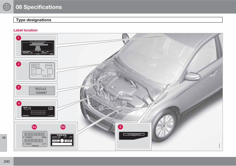
08 Specifications
Type designations
08
290
Label location
08 Specifications
Type designations
08
291
Knowing the car's type designation, vehicleidentification and engine numbers can facili-tate all contact with an authorised Volvo dealerregarding the car and when ordering spareparts and accessories.
Type designation, vehicle identificationnumber, maximum permissible weights,codes for colour and upholstery and typeapproval number. The label is visible whenthe right rear door is opened.
Label for parking heater.
Engine code, component and serial num-bers.
The engine oil label specifies oil grade andviscosity.
Gearbox type designation and serial num-ber.
Manual gearbox
Automatic gearbox
Car's identification number. (VIN VehicleIdentification Number)
Further information on the car is presented inthe registration document.
NOTE
The labels shown in the owner's manual arenot provided as exact reproductions ofthose in the car. The purpose is to showtheir approximate appearance and locationin the car. The information that applies toyour car in particular is available on the labelin question in your car.
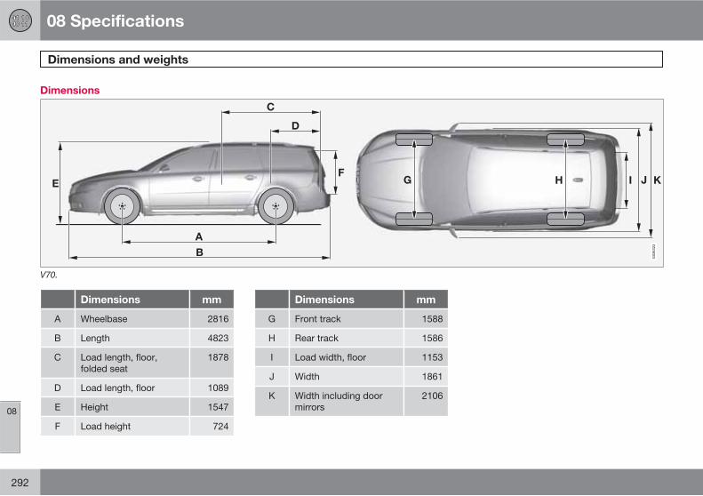
08 Specifications
Dimensions and weights
08
292
Dimensions
V70.
Dimensions mm
A Wheelbase 2816
B Length 4823
C Load length, floor,folded seat
1878
D Load length, floor 1089
E Height 1547
F Load height 724
Dimensions mm
G Front track 1588
H Rear track 1586
I Load width, floor 1153
J Width 1861
K Width including doormirrors
2106

08 Specifications
Dimensions and weights
08
��
293
XC70.
Dimensions mm
A Wheelbase 2815
B Length 4838
C Load length, floor,folded seat
1878
D Load length, floor 1089
E Height 1604
F Load height 724
G Front track 1604
Dimensions mm
H Rear track 1570
I Load width, floor 1153
J Width 1861
K Width including doormirrors
2119
Weights
Kerb weight includes the driver, the fuel tank90% full and all fluids.
The weight of passengers and accessories,and towball load (when a trailer is hitched, seetable page 295) influences the payload and isnot included in the kerb weight.
Permitted max. load = Gross vehicle weight -Kerb weight.

08 Specifications
Dimensions and weights
08
294
NOTE
The documented kerb weight applies tocars in the standard version - i.e. a car with-out extra equipment or accessories. Thismeans that for every accessory added theloading capacity of the car is reduced cor-respondingly by the weight of the acces-sory.
Examples of accessories that reduce load-ing capacity are the Kinetic/Momentum/Summum equipment levels, as well as otheraccessories such as Towbar, Load carriers,Space box, Audio system, Auxiliary lamps,GPS, Fuel-driven heater, Safety grille, Car-pets, Cargo cover, Power seats, etc.
Weighing the car is a certain way of ascer-taining the kerb weight of your own partic-ular car.
WARNING
The car's driving characteristics changedepending on how heavily it is loaded andhow the load is distributed.
For information on decal location, see page 290.
Max. gross vehicle weight
Max. train weight (car+trailer)
Max. front axle load
Max. rear axle load
Equipment level
Max. load: See registration document.
Max. roof load: 100 kg.
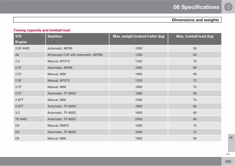
08 Specifications
Dimensions and weights
08
��
295
Towing capacity and towball load
V70
Engine
Gearbox Max. weight braked trailer (kg) Max. towball load (kg)
2.0F AWD Automatic, MPS6 1000 50
All All (except 2.0F with Automatic, MPS6) 1200 50
2.0 Manual, MTX75 1320 75
2.0T Automatic, MPS6 1800 90
2.0T Manual, M66 1800 90
2.0F Manual, MTX75 1320 75
2.5T Manual, M66 1600 75
2.5T Automatic, TF-80SC 1800 90
2.5FT Manual, M66 1600 75
2.5FT Automatic, TF-80SC 1800 90
3.2 Automatic, TF-80SC 1800 90
T6 AWD Automatic, TF-80SC 2000 90
D3 Manual, MMT6 1600 75
D3 Automatic, TF-80SC 1600 75
D5 Manual, M66 1800 90

08 Specifications
Dimensions and weights
08
296
V70
Engine
Gearbox Max. weight braked trailer (kg) Max. towball load (kg)
D5 Automatic, TF-80SC 2000 90
D5 AWD Automatic, TF-80SC 2000 90
XC70
Engine
Gearbox Max. weight braked trailer (kg) Max. towball load (kg)
All All (except 2.0F with Automatic, MPS6) 1200 50
D3 Manual, M66 1600 75
D3 Automatic, TF-80SC 1600 75
D5 AWD Manual, M66 2100 90
D5 AWD Automatic, TF-80SC 2100 90
T6 AWD Automatic, TF-80SC 2000 90
2.4D AWD Manual, M66 2100 90
2.4D AWD Automatic, TF-80SC 2100 90
3.2 AWD Automatic, TF-80SC 1800 90
Max. weight unbraked trailer (kg) Max. towball load (kg)
750 50

08 Specifications
Dimensions and weights
08
297
NOTE
The use of a stabiliser hitch on the towingbracket is recommended for trailers heavierthan 1800 kg.
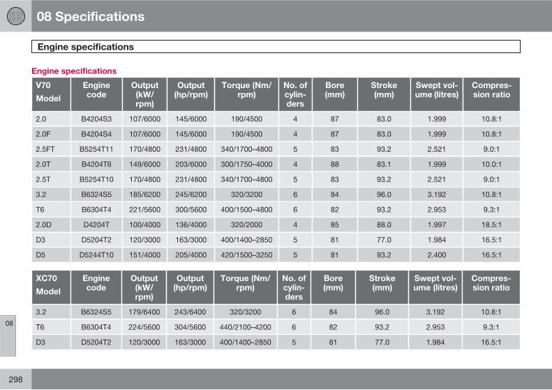
08 Specifications
Engine specifications
08
298
Engine specifications
V70
Model
Enginecode
Output(kW/rpm)
Output(hp/rpm)
Torque (Nm/rpm)
No. ofcylin-ders
Bore(mm)
Stroke(mm)
Swept vol-ume (litres)
Compres-sion ratio
2.0 B4204S3 107/6000 145/6000 190/4500 4 87 83.0 1.999 10.8:1
2.0F B4204S4 107/6000 145/6000 190/4500 4 87 83.0 1.999 10.8:1
2.5FT B5254T11 170/4800 231/4800 340/1700–4800 5 83 93.2 2.521 9.0:1
2.0T B4204T6 149/6000 203/6000 300/1750–4000 4 88 83.1 1.999 10.0:1
2.5T B5254T10 170/4800 231/4800 340/1700–4800 5 83 93.2 2.521 9.0:1
3.2 B6324S5 185/6200 245/6200 320/3200 6 84 96.0 3.192 10.8:1
T6 B6304T4 221/5600 300/5600 400/1500–4800 6 82 93.2 2.953 9.3:1
2.0D D4204T 100/4000 136/4000 320/2000 4 85 88.0 1.997 18.5:1
D3 D5204T2 120/3000 163/3000 400/1400–2850 5 81 77.0 1.984 16.5:1
D5 D5244T10 151/4000 205/4000 420/1500–3250 5 81 93.2 2.400 16.5:1
XC70
Model
Enginecode
Output(kW/rpm)
Output(hp/rpm)
Torque (Nm/rpm)
No. ofcylin-ders
Bore(mm)
Stroke(mm)
Swept vol-ume (litres)
Compres-sion ratio
3.2 B6324S5 179/6400 243/6400 320/3200 6 84 96.0 3.192 10.8:1
T6 B6304T4 224/5600 304/5600 440/2100–4200 6 82 93.2 2.953 9.3:1
D3 D5204T2 120/3000 163/3000 400/1400–2850 5 81 77.0 1.984 16.5:1

08 Specifications
Engine specifications
08
299
XC70
Model
Enginecode
Output(kW/rpm)
Output(hp/rpm)
Torque (Nm/rpm)
No. ofcylin-ders
Bore(mm)
Stroke(mm)
Swept vol-ume (litres)
Compres-sion ratio
D5 D5244T10 151/4000 205/4000 420/1500–3250 5 81 93.2 2.400 16.5:1
2.4D D5244T16A 120/4000 163/4000 420/1750–3000 5 81 93.2 2.400 16.5:1
A Certain markets

08 Specifications
Engine oil
08
300
Adverse driving conditions
Adverse driving conditions can lead to abnor-mally high oil temperature or oil consumption.Below are some examples of adverse drivingconditions.
Check the oil level more frequently for longjourneys:
• towing a caravan or trailer
• in mountainous regions
• at high speeds
• in temperatures colder than -30 °C or hot-ter than +40 °C
The above also apply to shorter driving dis-tances at low temperatures.
Choose a fully synthetic engine oil for adversedriving conditions. It provides extra protectionfor the engine.
Volvo recommends Castrol oil products.
IMPORTANT
In order to fulfil the requirements for theengine's service intervals all engines arefilled with a specially adapted syntheticengine oil at the factory. The choice of oilhas been made very carefully with regard toservice life, starting characteristics, fuelconsumption and environmental impact.
An approved engine oil must be used inorder that the recommended service inter-vals can be applied. Only use a prescribedgrade of oil for both filling and oil change,otherwise you will risk affecting service life,starting characteristics, fuel consumptionand environmental impact.
Volvo Car Corporation disclaims all war-ranty liability if engine oil of the prescribedgrade and viscosity is not used.
Viscosity chart

08 Specifications
Engine oil
08
301
Engine oil grade
Engine variant Engine code Recommended oil grade Volume between
MIN and MAX (litres)
Volume, incl. oil filter
(litres)
2.5FT B5254T11 Oil grade: ACEA A5/B5
Viscosity: SAE 0W–30
1.3 5.5
2.5 B5254T10 1.3 5.5
3.2 B6324S5 1.2 6.8
T6 B6304T4 1.2 6.8
D3 D5204T2 1.0 5.9
D5 D5244T10 1.0 5.9
2.0 B4204S3 Oil grade: ACEA A5/B5
Viscosity: SAE 5W–30
In the event of adverse conditionsuse ACEA A5/B5 SAE 0W-30
0,8 4.3
2.0F B4204S4 0,8 4.3
2,5T B4204T6 0.6 4,1
1.6D D4164T 1.0 3.8

08 Specifications
Fluids and lubricants
08
302
Other fluids and lubricants
Manual gearbox Volume (litres) Prescribed transmission fluid
MMT6 1.7
BOT 350M3MTX75 1.8
M66 1.9
Automatic gearbox Volume (litres) Prescribed transmission fluid
MPS6 7.3BOT 341
TF-80SC 7.0
Fluid System Volume (litres) Prescribed grade
Coolant 2.0, 2.0F 7.8Coolant recommended by Volvo mixedwith 50% waterA, see the packaging.
2.0T, 2.5, 2.5FT, 3.2 and T6 8.9
D3 and D5 8.9
Brake fluid Brake system 0.6 DOT 4+
Power steering fluid Power steering – WSS M2C204-A2 or equivalent prod-uct.
Washer fluid Cars with headlamp washing 6.5 Use a washer antifreeze recommendedby Volvo, mixed with water.Cars without headlamp washing 4.5

08 Specifications
Fluids and lubricants
08
303
Fluid System Volume (litres) Prescribed grade
Fuel Petrol engine approx. 70 Petrol:see page 220
Diesel engine approx. 70 Diesel: see page 221
A Water quality must fulfil the standard STD 1285.1.
NOTE
Under normal driving conditions, the gear-box oil does not need to be changed duringits service life. However, this may be nec-essary under adverse driving conditions,see page 302.

08 Specifications
Fuel
08
304
CO2 emissions and fuel consumption
V70 A B C
2.0 278 11.7 164 6.9 206 8.6
2.0FA 278 11.7 164 6.9 206 8.6
2.0FA 278 11.8 171 7.2 210 8.8
2.0T 259 11.1 148 6.4 189 8.1
2.0T 264 11.3 155 6.7 195 8.4
2.5T 299 12.5 157 6.6 209 8.8
2.5T 339 14.2 170 7.1 232 9.7
2.5FTA 299 12.5 157 6.6 209 8.8
2.5FTA 339 14.2 170 7.1 232 9.7
3,2 308 13.2 160 6.9 214 9.2
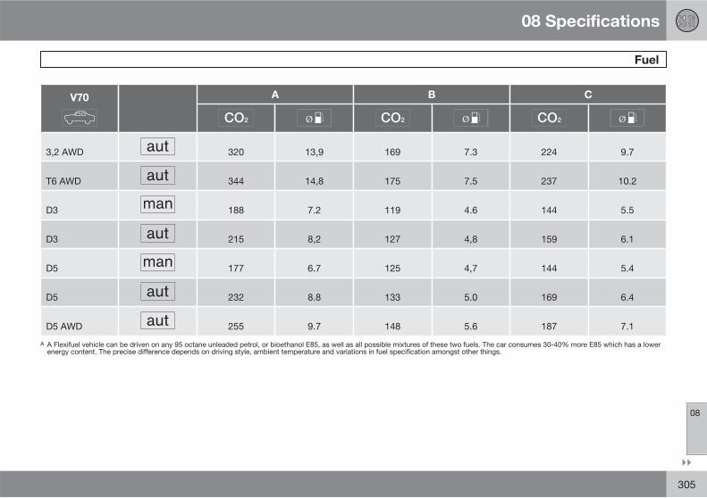
08 Specifications
Fuel
08
��
305
V70 A B C
3,2 AWD 320 13,9 169 7.3 224 9.7
T6 AWD 344 14,8 175 7.5 237 10.2
D3 188 7.2 119 4.6 144 5.5
D3 215 8,2 127 4,8 159 6.1
D5 177 6.7 125 4,7 144 5.4
D5 232 8.8 133 5.0 169 6.4
D5 AWD 255 9.7 148 5.6 187 7.1
A A Flexifuel vehicle can be driven on any 95 octane unleaded petrol, or bioethanol E85, as well as all possible mixtures of these two fuels. The car consumes 30-40% more E85 which has a lowerenergy content. The precise difference depends on driving style, ambient temperature and variations in fuel specification amongst other things.
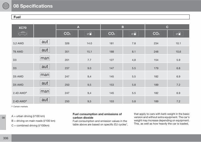
08 Specifications
Fuel
08
306
XC70 A B C
3,2 AWD 326 14.0 181 7.8 234 10.1
T6 AWD 351 15,1 188 8.1 248 10,6
D3 201 7.7 127 4,8 154 5.9
D3 237 9.0 147 5.5 179 6.8
D5 AWD 247 9,4 145 5.5 182 6.9
D5 AWD 250 9,5 153 5.8 189 7.2
2.4D AWDA 247 9,4 145 5.5 182 6.9
2.4D AWDA 250 9,5 153 5.8 189 7.2
A Certain markets
A = urban driving (l/100 km)
B = driving on main roads (l/100 km)
C = combined driving (l/100km)
Fuel consumption and emissions of
carbon dioxide
Fuel consumption and emission values in thetable above are based on specific EU cycles1,
that apply to cars with kerb weight in the basicversion and without extra equipment. The car'sweight may increase depending on equipment.This, as well as how heavily the car is loaded,

08 Specifications
Fuel
08
307
increases fuel consumption and carbon diox-ide emissions.
There are several reasons for increased fuelconsumption compared with the table's val-ues. Examples of this are:
• The driver's driving style.
• If the customer has specified wheels largerthan those fitted as standard on the mod-el's basic version, then resistance increa-ses.
• High speed results in increased wind resis-tance.
• Fuel quality, road and traffic conditions,weather and the condition of the car.
Even a combination of the above-mentionedexamples can result in significantly improvedconsumption. For further information, pleaserefer to the regulations referred to 1.
Large deviations in fuel consumption may arisein a comparison with the EU driving cycles1
which are used in the certification of the carand on which the consumption figures in thetable are based.
To bear in mind
Tips that the driver can use in order to reduceconsumption:
• Drive gently and avoid unnecessary accel-eration as well as braking too hard.
• Drive with the correct air pressure in thetyres and check this regularly - select ECOtyre pressure for best results, see the tyrepressure table on page 248.
• Choice of tyres can affect fuel consump-tion - seek advice on suitable tyres from adealer.
See further information and more advice onpages 12 and 216.
See page 220 for general information on fuel.
1 Official fuel consumption figures are based on two standardised driving cycles in a laboratory environment ("EU driving cycles") all in accordance with EU Directive 80/1268/EEC (Euro 4), EU Regulationno 682/2008 (Euro 5) and UN ECE Regulation no 101. The regulations cover the driving cycles for city driving and driving on main roads. - City driving - the measurement starts with cold startingthe engine. The driving is simulated. - Driving on main roads - the car is accelerated and braked at speeds between 0-120 km/h. The driving is simulated. - The V70 with the D5 engine and 6-speedmanual transmission is started in 2nd gear under normal conditions. The value for combined driving, which is reported in the table, is a combination of city driving and driving on main roads, inaccordance with legal requirements. CO2 emissions - the exhaust gases are collected in order to calculate the carbon dioxide emissions during the two driving cycles. These are then analysed andgive the value for CO2 emissions.

08 Specifications
Wheel and tyres, dimensions and pressure
08
308
Approved dimensions
In certain countries not all approved dimen-sions are indicated by the registration docu-ment or other documents. The table below
shows all approved combinations of wheelrims and tyres, and the lowest permitted loadindex (LI) and speed rating (SS). Information onengine, front-wheel drive (FWD) or all-wheel
drive (AWD) and the type of transmission isneeded to read the table. For information withrespect to these details, see page 290.
V70
Engine
FWD/
AWD
man/
aut
LI SS 205/60R16
7Jx16x50
225/55R16
7Jx16x50
225/50R17
7Jx17x50
7.5Jx17x55
245/45R17
8Jx17x55
245/40R18
8Jx18x55
T6 B6304T4 AWD aut 95 W -
3.2 B6324S5 FWD aut 94 V -
3.2 B6324S5 AWD aut 95 V -
D5 D5244T10 FWD man/aut 94 V -
D5 D5244T10 AWD aut 95 V -
D3 D5204T2 FWD man 94 V
aut 94 H
2.5T B5254T10 FWD man/aut 94 V
2.5T B5254T11 FWD man/aut 94 V - -
2.0T B4204T6 FWD man/aut 92 V
2.0 B4204S3 FWD man/aut 92 H
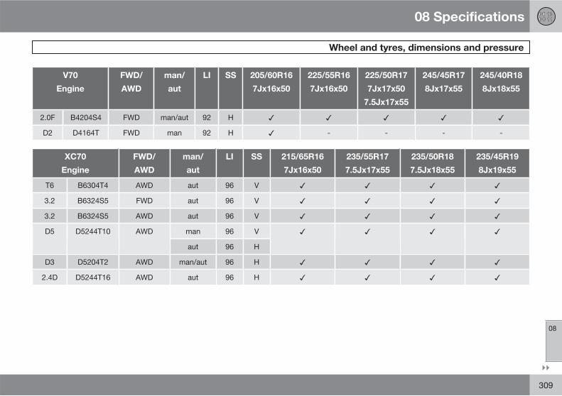
08 Specifications
Wheel and tyres, dimensions and pressure
08
��
309
V70
Engine
FWD/
AWD
man/
aut
LI SS 205/60R16
7Jx16x50
225/55R16
7Jx16x50
225/50R17
7Jx17x50
7.5Jx17x55
245/45R17
8Jx17x55
245/40R18
8Jx18x55
2.0F B4204S4 FWD man/aut 92 H
D2 D4164T FWD man 92 H - - - -
XC70
Engine
FWD/
AWD
man/
aut
LI SS 215/65R16
7Jx16x50
235/55R17
7.5Jx17x55
235/50R18
7.5Jx18x55
235/45R19
8Jx19x55
T6 B6304T4 AWD aut 96 V
3.2 B6324S5 FWD aut 96 V
3.2 B6324S5 AWD aut 96 V
D5 D5244T10 AWD man 96 V
aut 96 H
D3 D5204T2 AWD man/aut 96 H
2.4D D5244T16 AWD aut 96 H
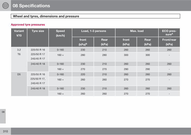
08 Specifications
Wheel and tyres, dimensions and pressure
08
310
Approved tyre pressures
Variant
V70
Tyre size Speed
(km/h)
Load, 1-3 persons Max. load ECO pres-
sureA
front
(kPa)B
Rear
(kPa)
front
(kPa)
Rear
(kPa)
Front/rear
(kPa)
3.2
T6
225/55 R 16
225/50 R 17
245/45 R 17
0-160 230 210 260 260 260
160 + 280 280 300 300 -
245/40 R 18 0-160 230 210 260 260 260
160 + 270 270 290 290 -
D5 225/55 R 16
225/50 R 17,
245/45 R 17
0-160 220 210 260 260 260
160 + 260 260 270 270 -
245/40 R 18 0-160 230 210 260 260 260
160 + 260 260 270 270 -

08 Specifications
Wheel and tyres, dimensions and pressure
08
��
311
Variant
V70
Tyre size Speed
(km/h)
Load, 1-3 persons Max. load ECO pres-
sureA
front
(kPa)B
Rear
(kPa)
front
(kPa)
Rear
(kPa)
Front/rear
(kPa)
2.0
2.0F
2.5
D2
D3
225/55 R 16
225/50 R 17
245/45 R 17
0-160 220 210 260 260 260
160 + 260 260 270 270 -
245/40 R 18 0-160 230 210 260 260 260
160 + 260 260 270 270 -
205/60 R 16 0-160 230 210 260 260 260
160 + 270 270 290 290 -
Temporary Spare Tyre max. 80 420 420 420 420 -
A Economical driving.B In certain countries there is the "bar" unit beside the SI unit "Pascal": 1 bar = 100 kPa.

08 Specifications
Wheel and tyres, dimensions and pressure
08
312
Variant
XC70
Tyre size Speed
(km/h)
Load, 1 - 3 persons Max. load ECO pres-
sureA
front
(kPa)B
Rear
(kPa)
front
(kPa)
Rear
(kPa)
Front/rear
(kPa)
All engines 215/65 R 16
235/55 R 17
235/50 R 18
235/45 R 19
0 - 160 230 230 260 260 260
160 + 240 240 280 280 -
Temporary Spare Tyre max. 80 420 420 420 420 -
A Economical driving.B In certain countries there is the "bar" unit beside the SI unit "Pascal": 1 bar = 100 kPa.

08 Specifications
Electrical system
08
313
Electrical system
The car has a voltage-regulated AC alternator.The electrical system is single-pole and usesthe chassis and engine casing as a conductor.
The battery capacity is dependent upon theequipment level in the vehicle.
IMPORTANT
If the battery is replaced, replace it with abattery of the same cold start capacity andreserve capacity as the original (see thedecal on the battery).
Battery
Voltage (V) Cold start capacity,
CCA - Cold Cranking Amperes (A)
Reserve capacity
(minutes)
12 520–800 100–160
12 520–700 100–135
12 700–800 135–160
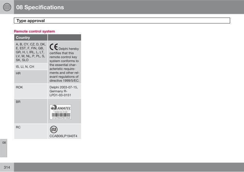
08 Specifications
Type approval
08
314
Remote control system
Country
A, B, CY, CZ, D, DK,E, EST, F, FIN, GB,GR, H, I, IRL, L, LT,LV, M, NL, P, PL, S,SK, SLO
Delphi herebycertifies that thisremote control keysystem conforms tothe essential char-acteristic require-ments and other rel-evant regulations ofdirective 1999/5/EC.
IS, LI, N, CH
HR
ROK Delphi 2003-07-15,Germany R-LPD1-03-0151
BR
RC
CCAB06LP1940T4

08 Specifications
Symbols in the display
08
��
* Option/accessory, for more information, see Introduction. 315
General
There are a variety of different symbols in thedisplay in the car. The symbols are divided intowarning, indicator and information symbols.Shown below are the most common symbolswith their meanings and a reference to wherein the manual further information can be found.For more information on symbols and textmessages, see pages 70, 71 and 134.
The red warning symbol illuminateswhen a fault has been indicated which couldaffect the safety and/or driveability of the car.At the same time an explanatory text is dis-played in the information display.
The yellow information symbol illumi-nates, in combination with text in the informa-tion display, when a deviation in any of the car'ssystems has occurred. The yellow symbolinformation can also illuminate in combinationwith other symbols.
Symbols in the display
Indicator and warning symbols in the
combined instrument panel
Sym-bol
Meaning Page
Low oil pressure 71
Parking brake 71, 122,123
Airbags - SRS 19, 71
Seatbelt reminder 16, 71
Alternator not charg-ing
71
Fault in the brakesystem
71, 119
Warning, safetymode
19, 30,71, 73
Indicator and information symbols in the
combined instrument panel
Sym-bol
Meaning Page
Fault in the ABL sys-tem*
70, 83
Emissions system 70
Fault in the ABS sys-tem
70, 119
Rear fog lamp on 70, 85
Stability system,DSTC, Hill descentcontrol
70, 120,168
Engine preheater(diesel)
70
Low level in fuel tank 70, 145
Information, read dis-play text
70
Main beam on 70, 83

08 Specifications
Symbols in the display
08
316 * Option/accessory, for more information, see Introduction.
Sym-bol
Meaning Page
Left-hand directionindicators
70
Right-hand directionindicators
70
Other information symbols in the
combined instrument panel
Sym-bol
Meaning Page
Adaptive cruise con-trol*
171, 175,179
Adaptive cruise con-trol*
179
Adaptive cruise con-trol*, Distance Alert*
179, 182
Adaptive cruise con-trol*, Distance Alert*
179, 182
Adaptive cruise con-trol*
179
Adaptive cruise con-trol*, Distance Alert*
175, 181
Sym-bol
Meaning Page
Adaptive cruise con-trol*, Distance Alert*
175, 181
Adaptive cruise con-trol*
175
Radar sensor* 179, 188
Camera sensor*,Laser sensor *
188, 191,194
Auto Brake*, Dis-tance Alert*, Collisionwarning system *
182, 188G025102
Fuel-driven engineblock heater andpassenger compart-ment heater*
145
ABL system* 83
Sym-bol
Meaning Page
Fuel filler flap, right-hand side
219
Low battery 145
Parking brake 123
Rain sensor* 92
Driver Alert System* 191, 191
Driver Alert System*,Lane DepartureWarning *
191, 194
Driver Alert System*,Lane DepartureWarning *
194
Driver Alert System*,Time for a break
191

08 Specifications
Symbols in the display
08
* Option/accessory, for more information, see Introduction. 317
Information symbols in the centre
console display
Sym-bol
Meaning Page
Audio files 153
Directory in CD disc 153
Traffic information 156
Phone* 205, 210
Bluetooth TM hands-free *
206, 208
Parking assistance* 196
Information symbols in the roof console
display
Sym-bol
Meaning Page
Seatbelt reminder 17
Airbag, passengerseat, activated
22, 23
Airbag, passengerseat, deactivated
23
09 Alphabetical Index
09
318
A
ACC – Adaptive cruise control................. 173
Active Bending Lights (ABL)...................... 83
Active chassis – FOUR-C........................ 170
Active Xenon headlamps........................... 83
Adaptation............................................... 110
Adapting driving characteristics.............. 170
Adaptive cruise control............................ 173fault tracing......................................... 178radar sensor........................................ 177
Adaptive cruise control fault tracing........ 178
Additional heater (Diesel)......................... 147
Adjusting headlamp pattern...................... 87halogen headlamp................................ 88
Adjusting the steering wheel...................... 81
Airbagactivating/deactivating, PACOS........... 22driver's and front passenger side......... 20key switch off........................................ 22
AIRBAG ..................................................... 20
Airbag system ........................................... 19
Air conditioning........................................ 141general................................................ 137
Air conditioning, AC................................. 141
Air distribution.................................. 138, 143
Air vents................................................... 139
Alarm.......................................................... 62alarm indicator...................................... 62alarm signals......................................... 62arming................................................... 62checking the alarm............................... 46deactivating.......................................... 62deactivating a triggered alarm.............. 62reduced alarm level.............................. 63temporary disarming of the alarm........ 63testing the alarm system...................... 63
Alcolock................................................... 103
Allergy and asthma inducing sub-stances.................................................... 138
All-wheel drive, AWD............................... 117
All Wheel Drive (AWD).............................. 117
Approach light, duration............................ 87
Audioheadphones socket............................ 149rear control panel................................ 149settings............................................... 149surround............................................. 148
Audio system........................................... 148functions............................................. 149overview.............................................. 148
Audio volumephone.................................................. 207phone/media player............................ 207ring signal, phone............................... 207
Autoclimate control settings...................... 141
Automatic car washes............................. 282
Automatic gearbox.................................. 112manual gear positions (Geartronic)..... 113towing and recovery........................... 237trailer................................................... 232
Automatic locking...................................... 56
Automatic relocking................................... 56
AUX.......................................................... 148
Auxiliary heater........................................ 147
AWD, All-wheel drive............................... 117
B
Backrest..................................................... 76front seat, lowering............................... 76
Backrest rear seat, lowering...................... 79
09 Alphabetical Index
09
319
Bag holder .............................................. 227
Battery............................................. 271, 313maintenance....................................... 271remote control key/PCC....................... 51start assistance................................... 111symbols on the battery....................... 271warning symbols................................. 271
Bioethanol E85........................................ 221
Blind spot (BLIS)...................................... 199
Blind Spot Information System, BLIS...... 199
Bluetoothhandsfree............................................ 205mute microphone............................... 207transfer call to mobile......................... 207
Bonnet, opening...................................... 256
Brake and clutch fluid.............................. 261
Brake light.................................................. 84
Brakes...................................................... 118anti-lock braking system, ABS........... 118brake light............................................. 84brake system...................................... 118electric parking brake......................... 122Emergency Brake Assistance, EBA ... 118emergency brake lights........................ 84
filling brake fluid.................................. 261symbols in the combined instrumentpanel................................................... 119
Built-in phone.......................................... 210
Bulbs, see Lighting.................................. 263
C
Callsfunctions during a call................ 210, 211incoming..................................... 206, 211operation..................................... 206, 210volume in phone................................. 211waiting................................................ 211
Call waiting.............................................. 211
Camera sensor........................................ 187
Car care................................................... 282
Car care, leather upholstery.................... 284
Cargo areacargo cover......................................... 230lighting.................................................. 86loading................................................ 224mounting points.................................. 225safety grille.......................................... 229safety net............................................ 228
Cargo cover............................................. 230
Car upholstery......................................... 284
Car wash.................................................. 282
Catalytic converter................................... 220recovery.............................................. 237
Centre console........................................ 130
Chassis settings...................................... 170
Checking and topping up the coolant..... 260
Children..................................................... 31child safety locks.................................. 38child seats and side airbags................. 24location in the car................................. 31safety.................................................... 31
Child safety locks...................................... 61
Child seat................................................... 31
Child seats................................................. 31integrated two-stage booster cushion. 36ISOFIX fixture system for child seats. . . 38recommended...................................... 33size classes for child seats with the ISO-FIX fixture system................................. 38upper mounting points for child seats.. 40
Cigarette lighter socket............................ 203

09 Alphabetical Index
09
320
Cleaningautomatic car washes......................... 282car wash............................................. 282rims..................................................... 283seatbelts............................................. 284upholstery........................................... 284
Clean Zone Interior Package (CZIP)........ 138
Climate control........................................ 137general................................................ 137sensors............................................... 137
Clock, setting............................................. 73
CO2 emissions ........................................ 304
Collision..................................................... 30
Collision warning..................................... 184
Collision warning systemradar sensor................................ 177, 184
Collision Warning with Auto Brake*......... 184
Colour code, paint................................... 285
Combined instrument panel.................... 134
Comfort inside the passenger compart-ment......................................................... 202
Compass................................................. 100calibration........................................... 100setting the zone.................................. 100
Condensation in headlamps.................... 282
Controlscentre console.................................... 130
Cooling system........................................ 216
Crash, see Collision................................... 30
Cruise control.......................................... 171
CZIP (Clear Zone Interior Package)......... 138
D
DAB, menu structure............................... 160
DAB Radio............................................... 158
Deadlocks.................................................. 59deactivation.......................................... 59temporary deactivation......................... 59
Defroster.................................................. 141
Diesel....................................................... 221
Diesel particle filter.................................. 222
Dipstick, electronic.................................. 259
Direction indicators.................................... 85
Disengaging the gear selector inhibitor... 114
Display lighting.......................................... 82
Distance Alert.......................................... 181
Dolby Surround Pro Logic II.................... 148
Door mirrors............................................... 97
Driver Alert Control.................................. 190
Driver Alert System.................................. 190
Driving...................................................... 216cooling system.................................... 216with the tailgate open......................... 217with trailer........................................... 231
Driving in water........................................ 216
Driving with a trailertowball load........................................ 293towing capacity.................................. 293
DSTC, see also Stability control system.. 168
E
ECC, electronic climate control............... 139
Economical driving.................................. 216
ECO pressure.......................................... 248
Electrical socket...................................... 204cargo area........................................... 227front seat............................................. 204
Electric parking brake.............................. 122low battery voltage............................. 122releasing automatically....................... 123releasing manually.............................. 123
09 Alphabetical Index
09
321
Emergency calls...................................... 210
Emergency equipmentwarning triangle.................................. 249
Emergency puncture repair..................... 250
Emissions of carbon dioxide................... 222
Engineoverheating......................................... 231starting................................................ 107
Engine block heater................................. 109fuel-driven........................................... 144
Engine braking, automatic....................... 120
Engine compartmentcoolant................................................ 260oil........................................................ 258overview.............................................. 257power steering fluid............................ 261
Engine oil......................................... 257, 300adverse driving conditions.................. 300capacities........................................... 300filter..................................................... 258oil grade.............................................. 300
Engine specifications............................... 298
Environmental labelling, FSC, owner'smanual....................................................... 12
Error messagesDriver Alert Control............................. 191Lane Departure Warning..................... 194see Messages and symbols............... 179
Error messages in BLIS........................... 200
Error messages in Distance Alert............ 182
Error messages in the Adaptive cruise con-trol............................................................ 179
Expectant mothers, seatbelt...................... 17
External dimensions................................ 292
F
Fan........................................................... 140
Fault tracing for the camera sensor......... 187
First aid equipment.................................. 249
First aid kit .............................................. 249
Flexifuel.................................................... 109adaptation........................................... 110
Floor mats................................................ 204
Fluids, capacities..................................... 302
Fluids and oils.......................................... 302
FM, menu structure................................. 157
Fog lampfront...................................................... 84
Fog lampsrear........................................................ 85
Fog lamps, on/off...................................... 84
Foot brake............................................... 118
FOUR-C – Active chassis........................ 170
FSC, environmental labelling..................... 12
Fuel.......................................................... 220fuel consumption................................ 304fuel economy...................................... 248fuel filter.............................................. 222
Fuse box.................................................. 274glovebox............................................. 278
Fuses....................................................... 274box in cargo area................................ 281changing............................................. 274general................................................ 274relay/fuse box in engine compart-ment.................................................... 275
Fuse tablefuses in engine compartment............. 276

09 Alphabetical Index
09
322
G
Gearbox................................................... 112automatic............................................ 112manual................................................ 112
Gear selector inhibitor............................. 114
Gear selector inhibitor, mechanical disen-gagement................................................. 114
Geartronic................................................ 113
Glasslaminated/reinforced............................. 95
Glovebox................................................. 203locking.................................................. 57
Gross vehicle weight............................... 293
H
Hazard warning flashers............................ 85
HDC......................................................... 120
Headlamp levelling.................................... 82
Headlamp pattern, adjusting..................... 87
Headlamp pattern adjustment Active Bending Lights .......................... 88
Headlamps............................................... 263
Headphones socket................................. 149
Head restraintcentre seat, rear.................................... 78lowering.......................................... 78, 79
Heated washer nozzles.............................. 93
Heating.................................................... 141rearview and door mirrors.................... 98rear window.......................................... 98seats................................................... 140
Heat-reflecting windscreen........................ 95
High engine temperature......................... 231
High-pressure headlamp washing............. 93
Hill Descent Control................................. 120
HomeLink .............................................. 125
Home safe lighting..................................... 87
Hoot........................................................... 81
Horn........................................................... 81
I
IAQS – Interior Air Quality System........... 138
IC – Inflatable Curtain................................ 26
IDIS – Intelligent Driver Information Sys-tem........................................................... 212
Ignition keys............................................... 74
IMEI number............................................ 213
Immobiliser................................................ 44
Indicator lamps, PCC................................ 46
Inflatable curtain........................................ 26
Information and warning symbols............. 70
Information button, PCC............................ 46
Information displays.................................. 69
Instrument lighting, see Lighting................ 82
Instrument overviewleft-hand drive....................................... 66right-hand drive.................................... 68
Instruments and controls........................... 66
Interior lighting, see Lighting..................... 86
Interior rearview mirror............................... 98automatic dimming............................... 98
Intermittent wiping..................................... 92
iPod , connection................................... 151
J
Jack......................................................... 247
09 Alphabetical Index
09
323
K
Kerb weight.............................................. 293
Key............................................................. 44
Key blade................................................... 47
Keyless drive...................................... 53, 107
Keyless start (keyless drive)............... 53, 107
Keylock.................................................... 114
Keypad in the steeringwheel................................. 81, 130, 171, 210
Key positions............................................. 74
L
Labels...................................................... 290
Laminated glass......................................... 95
Lamps, see Lighting................................ 263
Lane Departure Control........................... 193
Leather upholstery, washing instructions 284
Lighting.................................................... 263Active Xenon headlamps...................... 83approach light, duration....................... 87automatic lighting, passenger compart-ment...................................................... 86
bulbs, specifications........................... 268controls................................................. 86display lighting...................................... 82front fog lamps..................................... 84headlamp levelling................................ 82home safe lighting................................ 87in passenger compartment................... 86instrument lighting................................ 82main/dipped beam............................... 82position/parking lamps......................... 84rear fog lamp........................................ 85
Lighting, bulb replacement...................... 263cargo area........................................... 267dipped beam halogen......................... 264direction indicators............................. 265fog lamp.............................................. 266lamp housing, rear.............................. 266lamp housing, rear, direction indica-tors...................................................... 266main beam, Xenon lamp..................... 265main beam halogen............................ 264number plate lighting.......................... 267parking lamps..................................... 265side marker lamps.............................. 266vanity mirror........................................ 268
Light switches............................................ 82
Loadingcargo area........................................... 224general................................................ 224mounting points.................................. 225roof load............................................. 224
Lock confirmation ..................................... 44
Locking/unlockinginside.................................................... 56tailgate.................................................. 57
Locksautomatic locking................................. 56locking.................................................. 56unlocking.............................................. 56
Lubricants................................................ 302
Lubricants, capacities.............................. 302
M
Main/dipped beam, see Lightning............. 82
Maintenancerustproofing........................................ 283
Making calls..................................... 206, 210
Manual gearbox....................................... 112towing and recovery........................... 237
Manual gear positions (Geartronic).......... 113
09 Alphabetical Index
09
324
Max. roof load ......................................... 293
Memory function in seats.......................... 77
Menus and messages.............................. 130
Menu structureDAB.................................................... 160FM....................................................... 157
Messages and symbolsCollision Warning with Auto Brake..... 188Distance Alert..................................... 182Driver Alert Control............................. 191Lane Departure Warning..................... 194
Messages and symbols in the Adaptivecruise control........................................... 179
Messages in BLIS.................................... 200
Messages in the combined instrumentpanel........................................................ 134
Messages in the information display....... 168
Meters in the combined instrument panelfuel gauge............................................. 70speedometer......................................... 70tachometer........................................... 70
Misting..................................................... 141attending to the windows................... 137condensation in headlamps............... 282remove with the air vents................... 143timer function...................................... 142
Mobile phoneconnect............................................... 208handsfree............................................ 205register phone..................................... 205
O
Oil, see also Engine oil............................. 300
Oil level low.............................................. 258
Overheating............................................. 231
Owner's manual, environmental labelling.. 12
P
PACOS....................................................... 22
PACOS, switch.......................................... 22
Paintworkcolour code......................................... 285damage and touch-up........................ 285
Panel lighting............................................. 82
Panic function............................................ 45
Parking assistance................................... 196parking assistance sensors................ 198
Parking brake........................................... 122
Parking heater.......................................... 144battery and fuel................................... 144parking on a hill.................................. 144time setting......................................... 146
Passenger compartment......................... 202
Passenger compartment filter................. 138
Passenger compartment heaterfuel-driven........................................... 144
PCC – Personal Car Communicatorfunctions............................................... 45range............................................... 46, 47
Petrol grade............................................. 220
Phonebuilt-in, overview................................ 210connect............................................... 208handsfree............................................ 205incoming calls..................................... 206making calls........................................ 206messages........................................... 212on/off.................................................. 210phone book......................................... 208phone book, shortcut......................... 208receiving a call.................................... 207register phone..................................... 205ring signal........................................... 211SIM card............................................. 213
09 Alphabetical Index
09
325
Phone book............................................. 212
Pinch protection, sunroof........................ 102
Polishing.................................................. 283
Position/parking lamps.............................. 84
Power seat................................................. 77
Powershift gearbox.......................... 115, 237
Power sunroof......................................... 101
Power windows......................................... 95
Privacy locking........................................... 49
Puncture, see Tyres................................. 247
Putting calls on hold................................ 211
R
Radar sensor........................................... 173limitations........................................... 177
Rain sensor................................................ 92
Rear bulbslocation............................................... 267
Rear control panelaudio system...................................... 149
Rearview and door mirrorscompass............................................. 100door...................................................... 97
electrically retractable........................... 97heating.................................................. 98interior................................................... 98
Rear window, defrosting............................ 98
Recirculation............................................ 142
Recommendations during driving............ 216
Recommended child seats, table.............. 33
Recovery.................................................. 238
Refrigerant............................................... 137
Refuelling................................................. 219fuel cap............................................... 219fuel filler flap, electrical opening......... 219fuel filler flap, manual opening............ 219refuelling............................................. 219
Relay/fuse box: see Fuses....................... 274
Remote control, HomeLink programmable ................................... 125
Remote control key................................... 44battery replacement.............................. 51detachable key blade........................... 47functions............................................... 45range..................................................... 46
Remote control key system, type appro-val............................................................ 314
Resetting the door mirrors......................... 98
Resetting the power windows................... 96
Retractable power door mirrors................. 97
Reverse gear inhibitor.............................. 112
Rimscleaning.............................................. 283
Roof load, max. weight ........................... 293
Rustproofing............................................ 283
S
Safety grille.............................................. 229
Safety mode.............................................. 30
Safety net................................................. 228
Seat, see Seats.......................................... 76
Seatbeltrear seat................................................ 17seatbelt tensioner................................. 18
Seatbelt reminder...................................... 17
Seatbelts.................................................... 16
Seats.......................................................... 76head restraints, rear.............................. 78heating................................................ 140lowering the front backrest................... 76lowering the rear backrest.................... 79
09 Alphabetical Index
09
326
power seats.......................................... 77ventilated front seats.......................... 140
Securing loads (Loading)......................... 225
Service programme................................. 256
Set time interval....................................... 181
Side airbags............................................... 24
Signal input, external............................... 148
SIM card.................................................. 213
SIPS bags.................................................. 24
Soot filter................................................. 222
Soot filter full............................................ 222
Spare wheel............................................. 247temporary spare................................. 247
Spin control............................................. 168
Spin control function............................... 168
Stability and traction control system....... 168
Stability system....................................... 168
Stains....................................................... 284
Start assistance....................................... 111
Steering force, speed related.................. 170
Steering force level, see Steering force... 170
Steering lock............................................ 108
Steering wheel........................................... 81keypad.................. 81, 130, 148, 171, 210keypad, adaptive cruise control......... 175steering wheel adjustment.................... 81
Stone chips and scratches...................... 285
Storage spaces in the passenger compart-ment......................................................... 202
Sunroofopening and closing........................... 101pinch protection.................................. 102sunscreen........................................... 102ventilation position.............................. 101
Sunscreen, sunroof.................................. 102
Surround.................................................. 148
Symbols................................................... 168indicator symbols................................. 70information symbols............................. 70warning symbols................................... 70
Symbols and messagesCollision Warning with Auto Brake..... 188Distance Alert..................................... 182Driver Alert Control............................. 191Lane Departure Warning..................... 194
Symbols and messages in the Adaptivecruise control........................................... 179
T
Tailgate...................................................... 58locking/unlocking.................................. 57open...................................................... 58
Temperatureactual temperature............................. 137
Temperature control................................ 141
Testing the alarm system........................... 63
Timer........................................................ 142
Tools........................................................ 247
Total airing function........................... 56, 137
Towbar detachable, attachment ..................... 234detachable, removal .......................... 235
Towbar, see Towing equipment.............. 232
Towing..................................................... 237towing eye.......................................... 238
Towing capacity....................................... 293
Towing equipment................................... 232specifications...................................... 233
Towing eye.............................................. 238
Trailer....................................................... 231cable................................................... 231driving with a trailer............................ 231

09 Alphabetical Index
09
327
Transmission............................................ 112
Transponder.............................................. 95
Trip computer.......................................... 166
Trip meter.................................................. 73
Type approval, remote control key sys-tem........................................................... 314
Type designation..................................... 290
Tyresdimensions......................................... 308direction of rotation............................ 242driving characteristics......................... 242maintenance....................................... 242pressure...................................... 248, 308puncture repair................................... 250specifications.............................. 245, 308speed ratings...................................... 245tread wear indicators.......................... 243winter tyres......................................... 244
U
Unlockingfrom the inside...................................... 56from the outside................................... 56
USB, connection...................................... 151
V
Vanity mirror...................................... 86, 204
Ventilation................................................ 138
Vibration damper..................................... 232
W
Warning lampadaptive cruise control....................... 173collision warning system.................... 184stability and traction control system. . 168
Warning lampsairbags SRS.......................................... 71alternator not charging......................... 71fault in brake system............................ 71low oil pressure..................................... 71parking brake applied........................... 71seatbelt reminder.................................. 71warning................................................. 71
Warning soundcollision warning system.................... 184
Warning symbol, airbag system................ 19
Warning triangle....................................... 249
Washer fluid, filling................................... 270
Washer nozzles, heated............................. 93
Washersrear window.......................................... 93washer fluid, filling.............................. 270windscreen........................................... 93
Water and dirt-repellent coating................ 95
Water-repellent surface, cleaning............ 283
Waxing..................................................... 283
Weightskerb weight......................................... 293
Wheelschanging............................................. 246installation........................................... 246rims..................................................... 243snow chains........................................ 244spare wheel........................................ 247
Wheels and tyres..................................... 242
Whiplash injury, WHIPS............................. 27
WHIPSchild seat/booster cushion................... 27whiplash injury...................................... 27
Windows, rearview and door mirrors......... 95
Windscreen washing.................................. 93
Windscreen wipers.................................... 92rain sensor............................................ 92

09 Alphabetical Index
09
328
Winter driving........................................... 217
Winter tyres.............................................. 244
Wiper blades............................................ 269changing............................................. 269cleaning.............................................. 270replacing, rear window....................... 270service position................................... 269
Wipers and washing.................................. 92


���������������� ������������ ������������������������������������������������� �!"������©�����#�����$� %�� &�� ��!��&����