Embed Size (px)
Citation preview

VRML 98
Introduction to VRML 97
Lecturer
David R. Nadeau [email protected] http://www.sdsc.edu/~nadeau San Diego Supercomputer Center
Tutorial notes sections
Abstract Preface Lecturer biography Using the VRML examples Using the JavaScript examples Using the Java examples Tutorial slides

Introduction to VRML 97
Abstract
VRML (the Virtual Reality Modeling Language) has emerged as the de facto standard for describing3-D shapes and scenery on the World Wide Web. VRML’s technology has very broad applicability,including web-based entertainment, distributed visualization, 3-D user interfaces to remote webresources, 3-D collaborative environments, interactive simulations for education, virtual museums,virtual retail spaces, and more. VRML is a key technology shaping the future of the web.
Participants in this tutorial will learn how to use VRML 97 (a.k.a. ISO VRML, VRML 2.0, and MovingWorlds) to author their own 3-D virtual worlds on the World Wide Web. Participants will learn VRMLconcepts and terminology, and be introduced to VRML’s text format syntax. Participants also will learntips and techniques for increasing performance and realism. The tutorial includes numerous VRMLexamples and information on where to find out more about VRML features and use.
Introduction to VRML 97
Preface
Welcome to the Introduction to VRML 97 tutorial notes! These tutorial notes have been written togive you a quick, practical, example-driven overview of VRML 97, the Web’s Virtual RealityModeling Language. To do this, I’ve included over 500 pages of tutorial material with nearly 200images and over 100 VRML examples.
To use these tutorial notes you will need an HTML Web browser with support for viewing VRMLworlds. An up to date list of available VRML browsing and authoring software is available at:
The VRML Repository (http://vrml.sdsc.edu)
What’s included in these notes
These tutorial notes primarily contain two types of information:
1. General information, such as this preface 2. Tutorial slides and examples
The tutorial slides are arranged as a sequence of 500+ hyper-linked pages containing VRMLsyntax notes, VRML usage comments, or images of sample VRML worlds. Clicking on a sampleworld’s image, or the file name underneath it, loads the VRML world into your browser for you toexamine yourself.
You can view the text for any of the VRML worlds using a text editor and see how I created aparticular effect. In most cases, the VRML files contain extensive comments providinginformation about the techniques the file illustrates.
The tutorial notes provide a necessarily terse overview of VRML. I recommend that you invest inone of the VRML books on the market to get thorough coverage of the language. I am a co-authorof one such VRML book, The VRML 2.0 Sourcebook. Several other good VRML books are on themarket as well.
A word about VRML versions
VRML has evolved through several versions of the language, starting way back in late 1994.These tutorial notes cover VRML 97, the latest version of the language. To provide context, thefollowing table provides a quick overview of these VRML versions and the names they havebecome known by.
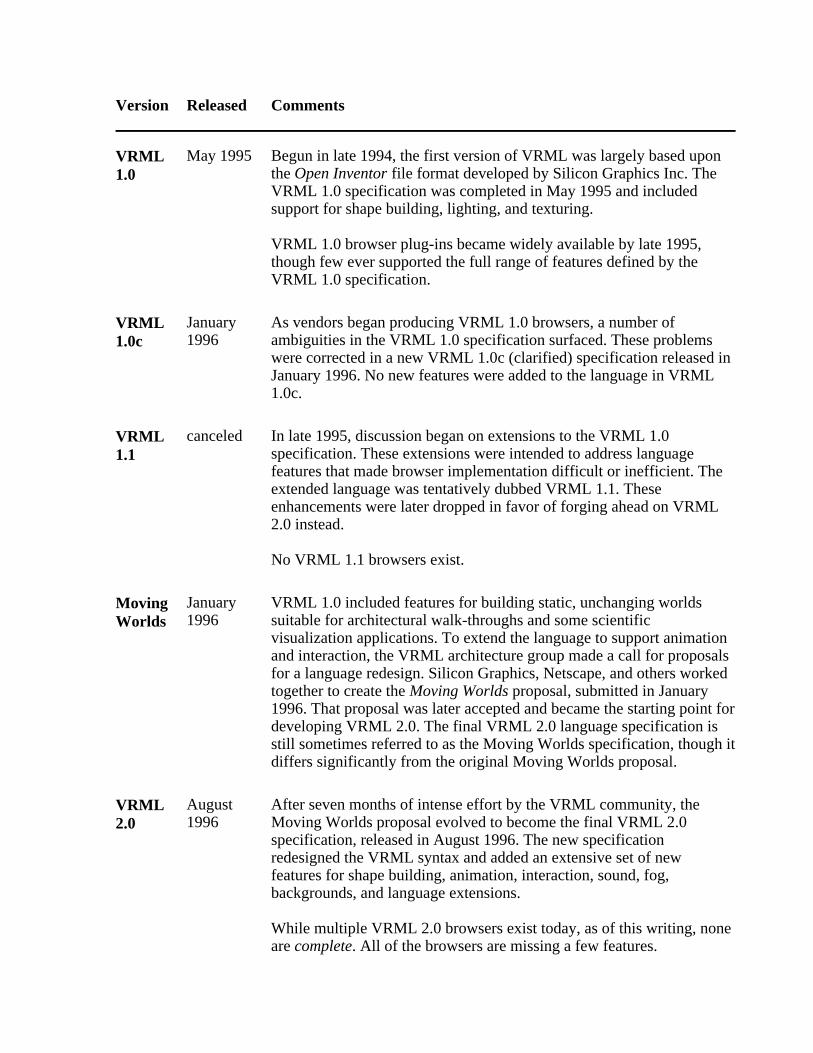
Version Released Comments
VRML1.0
May 1995 Begun in late 1994, the first version of VRML was largely based uponthe Open Inventor file format developed by Silicon Graphics Inc. TheVRML 1.0 specification was completed in May 1995 and includedsupport for shape building, lighting, and texturing.
VRML 1.0 browser plug-ins became widely available by late 1995,though few ever supported the full range of features defined by theVRML 1.0 specification.
VRML1.0c
January1996
As vendors began producing VRML 1.0 browsers, a number ofambiguities in the VRML 1.0 specification surfaced. These problemswere corrected in a new VRML 1.0c (clarified) specification released inJanuary 1996. No new features were added to the language in VRML1.0c.
VRML1.1
canceled In late 1995, discussion began on extensions to the VRML 1.0specification. These extensions were intended to address languagefeatures that made browser implementation difficult or inefficient. Theextended language was tentatively dubbed VRML 1.1. Theseenhancements were later dropped in favor of forging ahead on VRML2.0 instead.
No VRML 1.1 browsers exist.
MovingWorlds
January1996
VRML 1.0 included features for building static, unchanging worldssuitable for architectural walk-throughs and some scientificvisualization applications. To extend the language to support animationand interaction, the VRML architecture group made a call for proposalsfor a language redesign. Silicon Graphics, Netscape, and others workedtogether to create the Moving Worlds proposal, submitted in January1996. That proposal was later accepted and became the starting point fordeveloping VRML 2.0. The final VRML 2.0 language specification isstill sometimes referred to as the Moving Worlds specification, though itdiffers significantly from the original Moving Worlds proposal.
VRML2.0
August1996
After seven months of intense effort by the VRML community, theMoving Worlds proposal evolved to become the final VRML 2.0specification, released in August 1996. The new specificationredesigned the VRML syntax and added an extensive set of newfeatures for shape building, animation, interaction, sound, fog,backgrounds, and language extensions.
While multiple VRML 2.0 browsers exist today, as of this writing, noneare complete. All of the browsers are missing a few features.
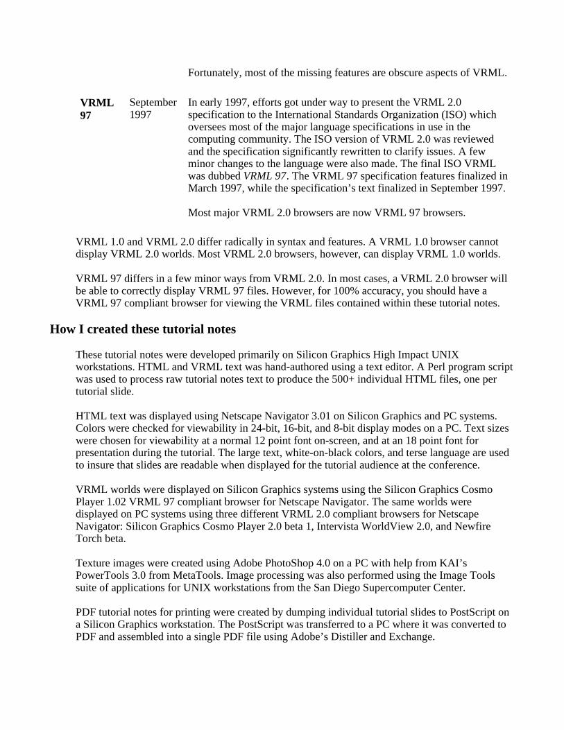
Fortunately, most of the missing features are obscure aspects of VRML.
VRML97
September1997
In early 1997, efforts got under way to present the VRML 2.0specification to the International Standards Organization (ISO) whichoversees most of the major language specifications in use in thecomputing community. The ISO version of VRML 2.0 was reviewedand the specification significantly rewritten to clarify issues. A fewminor changes to the language were also made. The final ISO VRMLwas dubbed VRML 97. The VRML 97 specification features finalized inMarch 1997, while the specification’s text finalized in September 1997.
Most major VRML 2.0 browsers are now VRML 97 browsers.
VRML 1.0 and VRML 2.0 differ radically in syntax and features. A VRML 1.0 browser cannotdisplay VRML 2.0 worlds. Most VRML 2.0 browsers, however, can display VRML 1.0 worlds.
VRML 97 differs in a few minor ways from VRML 2.0. In most cases, a VRML 2.0 browser willbe able to correctly display VRML 97 files. However, for 100% accuracy, you should have aVRML 97 compliant browser for viewing the VRML files contained within these tutorial notes.
How I created these tutorial notes
These tutorial notes were developed primarily on Silicon Graphics High Impact UNIXworkstations. HTML and VRML text was hand-authored using a text editor. A Perl program scriptwas used to process raw tutorial notes text to produce the 500+ individual HTML files, one pertutorial slide.
HTML text was displayed using Netscape Navigator 3.01 on Silicon Graphics and PC systems.Colors were checked for viewability in 24-bit, 16-bit, and 8-bit display modes on a PC. Text sizeswere chosen for viewability at a normal 12 point font on-screen, and at an 18 point font forpresentation during the tutorial. The large text, white-on-black colors, and terse language are usedto insure that slides are readable when displayed for the tutorial audience at the conference.
VRML worlds were displayed on Silicon Graphics systems using the Silicon Graphics CosmoPlayer 1.02 VRML 97 compliant browser for Netscape Navigator. The same worlds weredisplayed on PC systems using three different VRML 2.0 compliant browsers for NetscapeNavigator: Silicon Graphics Cosmo Player 2.0 beta 1, Intervista WorldView 2.0, and NewfireTorch beta.
Texture images were created using Adobe PhotoShop 4.0 on a PC with help from KAI’sPowerTools 3.0 from MetaTools. Image processing was also performed using the Image Toolssuite of applications for UNIX workstations from the San Diego Supercomputer Center.
PDF tutorial notes for printing were created by dumping individual tutorial slides to PostScript ona Silicon Graphics workstation. The PostScript was transferred to a PC where it was converted toPDF and assembled into a single PDF file using Adobe’s Distiller and Exchange.
Use of these tutorial notes
I am often asked if there are any restrictions on use of these tutorial notes. The answer is:
These tutorial notes are copyright (c) 1997 by David R. Nadeau. Users and possessors ofthese tutorial notes are hereby granted a nonexclusive, royalty-free copyright and designpatent license to use this material in individual applications. License is not granted forcommercial resale, in whole or in part, without prior written permission from the authors.This material is provided "AS IS" without express or implied warranty of any kind.
You are free to use these tutorial notes in whole or in part to help you teach your own VRMLtutorial. You may translate these notes into other languages and you may post copies of these noteson your own Web site, as long as the above copyright notice is included as well. You may not,however, sell these tutorial notes for profit or include them on a CD-ROM or other media productwithout written permission.
If you use these tutorial notes, I ask that you:
1. Give me credit for the original material 2. Tell me since I like hearing about the use of my material!
If you find bugs in the notes, please tell me. I have worked hard to try and make the notesbug-free, but if something slipped by, I’d like to fix it before others are confused by my mistake.
Contact
David R. Nadeau San Diego Supercomputer Center P.O. Box 85608 San Diego, CA 92186-9784
UPS, Fed Ex: 10100 Hopkins Dr. La Jolla, CA 92093-0505
(619) 534-5062 FAX: (619) 534-5152
[email protected] http://www.sdsc.edu/~nadeau
Introduction to VRML 97
Lecturer biography
David R. Nadeau Mr. Nadeau is a principal scientist at the San Diego Supercomputer Center (SDSC), specializing inscientific visualization and virtual reality. He is an author of technical papers on graphics andVRML and a co-author of two books on VRML (The VRML Sourcebook, and The VRML 2.0Sourcebook). He has taught VRML courses at conferences including SIGGRAPH 96-97, WebNet96-97, VRML 97, Eurographics 97, and Visualization 97, and is the creator of The VRMLRepository, a principal Web site for information on VRML software and documentation. Mr.Nadeau co-chaired VRML 95, the first conference on VRML, and the VRML Behavior Workshop,the first workshop on behavior support for VRML. He is SDSC’s representative in the VRMLConsortium.
Introduction to VRML 97
Using the VRML examples
These tutorial notes include over a hundred VRML files. Almost all of the provided worlds arelinked to from the tutorial slides pages.
VRML support
As noted in the preface to these tutorial notes, this tutorial covers VRML 97, the ISO standardversion of VRML 2.0. There are only minor differences between VRML 97 and VRML 2.0, soany VRML 97 or VRML 2.0 browser should be able to view any of the VRML worlds containedwithin these tutorial notes.
The VRML 97 (and VRML 2.0) language specifications are complex and filled with powerfulfeatures for VRML content authors. Unfortunately, the richness of the language makesdevelopment of a robust VRML browser difficult. As of this writing, there are nearly a dozenVRML browsers on the market, but none support all features in VRML 97 (despite press releasesto the contrary).
I am reasonably confident that all VRML examples in these tutorial notes are correct, though ofcourse I could have missed something. Chances are that if one of the VRML examples doesn’tlook right, the problem is with your VRML browser and not with the example. It’s a good idea toread carefully the release notes for your browser to see what features it does and does not support.It’s also a good idea to regularly check your VRML browser vendor’s Web site for updates. Theindustry is moving very fast and often produces new browser releases every month or so.
As of this writing, I have found that Silicon Graphics (SGI) Cosmo Player for PCs and SGI UNIXworkstations is the most complete and robust VRML 97 browser available. It is this browser that Iused for most of my VRML testing. On the Macintosh and non-SGI UNIX workstations, I wasunable to find a usable VRML browser with which to test the VRML tutorial examples.
What if my VRML browser doesn’t support a VRML feature?
If your VRML browser doesn’t support a particular VRML 97 feature, then those worlds that usethe feature will not load properly. Some VRML browsers display an error window when theyencounter an unsupported feature. Other browsers silently ignore features they do not support yet.
When your VRML browser encounters an unsupported feature, it may elect to reject the entireVRML file, or it may load only those parts of the world that it understands. When only part of aVRML file is loaded, those portions of the world that depend upon the unsupported features willdisplay incorrectly. Shapes may be in the wrong position, have the wrong size, be shadedincorrectly, or have the wrong texture colors. Animations may not run, sounds may not play, andinteractions may not work correctly.
For most worlds I have captured an image of the world and placed it on the tutorial slide page to

give you an idea of what the world should look like. If your VRML browser’s display doesn’t looklike the picture, chances are the browser is missing support for one or more features used by theworld. Alternately, the browser may simply have a bug or two.
In general, VRML worlds later in the tutorial use features that are harder for vendors to implementthan those features used earlier in the tutorial. So, VRML worlds at the end of the tutorial are morelikely to fail to load properly than VRML worlds early in the tutorial.
Introduction to VRML 97
Using the JavaScript examples
These tutorial notes include several VRML worlds that use JavaScript program scripts withinScript nodes. The text for these program scripts is included directly within the Script nodewithin the VRML file.
JavaScript support
The VRML 97 specification does not require that a VRML browser support the use of JavaScriptto create program scripts for Script nodes. Fortunately, most VRML browsers do supportJavaScript program scripts, though you should check your VRML browser’s release notes to besure it is JavaScript-enabled.
Some VRML browsers, particularly those from Silicon Graphics, support a derivative ofJavaScript called VRMLscript. The language is essentially identical to JavaScript. Because ofSilicon Graphics’ strength in the VRML market, most VRML browser vendors have modifiedtheir VRML browsers to support VRMLscript as well as JavaScript.
JavaScript and VRMLscript program scripts are included as text within the url field of a Script
node. To indicate the program script’s language, the field value starts with either "javascript: "for JavaScript, or "vrmlscript: " for VRMLscript, like this:
Script { field SFFloat bounceHeight 1.0 eventIn SFFloat set_fraction eventOut SFVec3f value_changed
url " vrmlscript: function set_fraction( frac, tm ) { y = 4.0 * bounceHeight * frac * (1.0 - frac); value_changed[0] = 0.0; value_changed[1] = y; value_changed[2] = 0.0; }"}
For compatibility with Silicon Graphics VRML browsers, all JavaScript program script examplesin these notes are tagged as "vrmlscript: ", like the above example. If you have a VRML browserthat does not support VRMLscript, but does support JavaScript, then you can convert the examplesto JavaScript simply by changing the tag "vrmlscript: " to "javascript: " like this:
Script { field SFFloat bounceHeight 1.0 eventIn SFFloat set_fraction eventOut SFVec3f value_changed
url " javascript: function set_fraction( frac, tm ) {
y = 4.0 * bounceHeight * frac * (1.0 - frac); value_changed[0] = 0.0; value_changed[1] = y; value_changed[2] = 0.0; }"}
What if my VRML browser doesn’t support JavaScript?
If your VRML browser doesn’t support JavaScript or VRMLscript, then those worlds that usethese languages will produce an error when loaded into your VRML browser. This is unfortunatesince JavaScript or VRMLscript is an essential feature that all VRML browsers should support. Irecommend that you consider getting a different VRML browser.
If you can’t get another VRML browser right now, there are only a few VRML worlds in thesetutorial notes that you will not be able to view. Those worlds are contained as examples in thefollowing tutorial sections:
Introducing script use Writing program scripts with JavaScript Creating new node types
So, if you don’t have a VRML browser with JavaScript or VRMLscript support, just skip theabove sections and everything will be fine.
Introduction to VRML 97
Using the Java examples
These tutorial notes include a few VRML worlds that use Java program scripts within Script
nodes. The text for these program scripts is included in files with .java file name extensions.Before use, you will need to compile these Java program scripts to Java byte-code contained infiles with .class file name extensions.
Java support
The VRML 97 specification does not require that a VRML browser support the use of Java tocreate program scripts for Script nodes. Fortunately, most VRML browsers do support Javaprogram scripts, though you should check your VRML browser’s release notes to be sure it isJava-enabled.
In principle, all Java-enabled VRML browsers identically support the VRML Java API asdocumented in the VRML 97 specification. Similarly, in principle, a compiled Java program scriptusing the VRML Java API can be executed on any type of computer within any brand of VRMLbrowser
In practice, neither of these ideal cases occurs. The Java language is supported somewhatdifferently on different platforms, particularly as the community transitions from Java 1.0 to Java1.1 and beyond. Additionally, the VRML Java API is implemented somewhat differently bydifferent VRML browsers, making it difficult to insure that a compiled Java class file will workfor all VRML browsers available now and in the future.
Because of Java incompatibilities observed with current VRML browsers, I have elected to notinclude compiled Java class files in these tutorial notes. Instead, I include the uncompiled Javaprogram scripts. Before use, you will need to compile the Java program scripts yourself on yourplatform with your VRML browser and your version of the Java language and support tools.
Compiling Java
To compile the Java examples, you will need:
The VRML Java API class files for your VRML browser A Java compiler
All VRML browsers that support Java program scripts supply their own set of VRML Java APIclass files. Typically these are automatically installed when you install your VRML browser.
There are multiple Java compilers available for most platforms. Sun Microsystems provides theJava Development Kit (JDK) for free from its Web site at http://www.javasoft.com. The JDKincludes the javac compiler and instructions on how to use it. Multiple commercial Javadevelopment environments are available from Microsoft, Silicon Graphics, Symantec, and others.
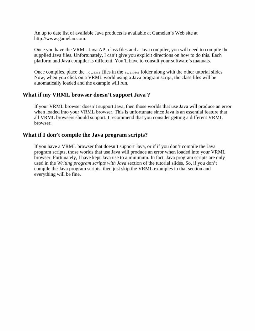
An up to date list of available Java products is available at Gamelan’s Web site athttp://www.gamelan.com.
Once you have the VRML Java API class files and a Java compiler, you will need to compile thesupplied Java files. Unfortunately, I can’t give you explicit directions on how to do this. Eachplatform and Java compiler is different. You’ll have to consult your software’s manuals.
Once compiles, place the .class files in the slides folder along with the other tutorial slides.Now, when you click on a VRML world using a Java program script, the class files will beautomatically loaded and the example will run.
What if my VRML browser doesn’t support Java ?
If your VRML browser doesn’t support Java, then those worlds that use Java will produce an errorwhen loaded into your VRML browser. This is unfortunate since Java is an essential feature thatall VRML browsers should support. I recommend that you consider getting a different VRMLbrowser.
What if I don’t compile the Java program scripts?
If you have a VRML browser that doesn’t support Java, or if if you don’t compile the Javaprogram scripts, those worlds that use Java will produce an error when loaded into your VRMLbrowser. Fortunately, I have kept Java use to a minimum. In fact, Java program scripts are onlyused in the Writing program scripts with Java section of the tutorial slides. So, if you don’tcompile the Java program scripts, then just skip the VRML examples in that section andeverything will be fine.


Introduction to VRML 97
Table of contents
Morning
Part 1 - Shapes, geometry, and appearance
Welcome!
Introducing VRML
Building a VRML world
Building primitive shapes
Transforming shapes
Controlling appearance with materials
Grouping nodes
Naming nodes
Summary examples
Part 2 - Animation, sensors, and geometry
Introducing animation
Animating transforms
Sensing viewer actions
Building shapes out of points, lines, and faces
Building elevation grids
Building extruded shapes
Controlling color on coordinate-based geometry

Controlling shading on coordinate-based geometry
Summary examples
Afternoon
Part 3 - Textures, lights, and environment
Mapping textures
Controlling how textures are mapped
Lighting your world
Adding backgrounds
Adding fog
Adding sound
Controlling the viewpoint
Controlling navigation
Sensing the viewer
Summary examples
Part 4 - Scripts and prototypes
Controlling detail
Introducing script use
Writing program scripts with JavaScript
Writing program scripts with Java
Creating new node types
Providing information about your world
Summary examples

Miscellaneous extensions
Conclusion


1Welcome!
Introduction to VRML 97
Schedule for the day
Tutorial scope

2
Welcome!
Introduction to VRML 97
Welcome to the tutorial!
Dave Nadeau San Diego Supercomputer Center

3
Welcome!
Schedule for the day
Part 1 Shapes, geometry, appearanceBreak
Part 2 Animation, sensors, geometryLunch
Part 3 Textures, lights, environmentBreak
Part 4 Scripts, prototypes

4
Welcome!
Tutorial scope
This tutorial covers VRML 97 The ISO standard revision of VRML 2.0
You will learn: VRML file structure Concepts and terminology Most shape building syntax Most sensor and animation syntax Most program scripting syntax Where to find out more

5Introducing VRML
What is VRML?
What do I need to use VRML?
Examples
How can VRML be used on a Web page?
What do I need to develop in VRML?
Should I use a text editor?
Should I use a world builder?
Should I use a 3D modeler and format translator?
Should I use a shape generator?
How do I get VRML software?

6
Introducing VRML
What is VRML?
VRML is: A simple text language for describing 3-Dshapes and interactive environments
VRML text files use a .wrl extension

7
Introducing VRML
What do I need to use VRML?
You can view VRML files using a VRMLbrowser:
A VRML helper-application A VRML plug-in to an HTML browser
You can view VRML files from your localhard disk, or from the Internet

8
Introducing VRML
Examples
[ temple.wrl ] [ cutplane.wrl ]
[ spiral.wrl ] [ floater.wrl ]

9
Introducing VRML
How can VRML be used on a Web page?
Fill Web page [ boxes.wrl ] Embed into Web page [ boxes1.htm ] Fill Web page frame [ boxes2.htm ] Embed into Web page frame [ boxes3.htm ] Embed multiple times [ boxes4.htm ]

10
Introducing VRML
What do I need to develop in VRML?
You can construct VRML files using: A text editor A world builder application A 3D modeler and format translator A shape generator (like a Perl script)

11
Introducing VRML
Should I use a text editor?
Pros: No new software to buy Access to all VRML features Detailed control of world efficiency
Cons: Hard to author complex 3D shapes Requires knowledge of VRML syntax

12
Introducing VRML
Should I use a world builder?
Pros: Easy 3-D drawing and animating userinterface Little need to learn VRML syntax
Cons: May not support all VRML features May not produce most efficient VRML

13
Introducing VRML
Should I use a 3D modeler and format translator?
Pros: Very powerful drawing and animatingfeatures Can make photo-realistic images too
Cons: May not support all VRML features May not produce most efficient VRML Not designed for VRML Often a one-way path from 3D modelerinto VRML Easy to make shapes that are too complex

14
Introducing VRML
Should I use a shape generator?
Pros: Easy way to generate complex shapes
Fractal mountains, logos, etc. Generate VRML from CGI Perl scripts Common to extend science applications togenerate VRML
Cons: Only suitable for narrow set of shapes Best used with other software

15
Introducing VRML
How do I get VRML software?
The VRML Repository at:
http://vrml.sdsc.edu
maintains uptodate information and links for:Browser softwareWorld builder softwareFile translatorsImage editorsJava authoring toolsTexture libraries
Sound librariesObject librariesSpecificationsTutorialsBooksand more...

16

17Building a VRML world
VRML file structure
A sample VRML file
Understanding the header
Understanding UTF8
Using comments
Using nodes
Using node type names
Using fields and values
Using field names
Using fields and values
Summary

18
Building a VRML world
VRML file structure
VRML files contain: The file header Comments - notes to yourself Nodes - nuggets of scene information Fields - node attributes you can change Values - attribute values more. . .

19
Building a VRML world
A sample VRML file
#VRML V2.0 utf8# A CylinderShape { appearance Appearance { material Material { } } geometry Cylinder { height 2.0 radius 1.5 }}

20
Building a VRML world
Understanding the header
#VRML V2.0 utf8
#VRML: File contains VRML text V2.0 : Text conforms to version 2.0 syntax utf8 : Text uses UTF8 character set

21
Building a VRML world
Understanding UTF8
utf8 is an international character set standard
utf8 stands for: UCS (Universal Character Set)Transformation Format, 8-bit
Encodes 24,000+ characters for manylanguages
ASCII is a subset

22
Building a VRML world
Using comments
# A Cylinder
Comments start with a number-sign (#) andextend to the end of the line

23
Building a VRML world
Using nodes
Cylinder {}
Nodes describe shapes, lights, sounds, etc.
Every node has: A node type (Shape, Cylinder , etc.) A pair of curly-braces Zero or more fields inside the curly-braces

24
Building a VRML world
Using node type names
Node type names are case sensitive Each word starts with an upper-casecharacter The rest of the word is lower-case
Some examples: AppearanceCylinderMaterialShape
ElevationGridFontStyleImageTextureIndexedFaceSet

25
Building a VRML world
Using fields and values
Cylinder { height 2.0 radius 1.5}
Fields describe node attributes
Every field has: A field name (height , radius , etc.) A data type (float, integer, etc.) A default value

26
Building a VRML world
Using field names
Field names are case sensitive The first word starts with a lower-casecharacter Each additional word starts with anupper-case character The rest of the word is lower-case
Some examples: appearanceheightmaterialradius
coordIndexdiffuseColorfontStyletextureTransform

27
Building a VRML world
Using fields and values
Different node types have different fields
Fields are optional A default value is used if a field is not given
Fields can be listed in any order The order doesn’t affect the node

28
Building a VRML world
Summary
The file header gives the version and encoding
Nodes describe scene content
Fields and values specify node attributes
Everything is case sensitive

29Building primitive shapes
Motivation
Example
Syntax: Shape
Specifying appearance
Specifying geometry
Syntax: Box
Syntax: Cone
Syntax: Cylinder
Syntax: Sphere
Syntax: Text
Syntax: FontStyle
Syntax: FontStyle
Syntax: FontStyle
Syntax: FontStyle
A sample primitive shape
A sample primitive shape
Building multiple shapes
A sample file with multiple shapes
A sample file with multiple shapes
Summary

30
Building primitive shapes
Motivation
Shapes are the building blocks of a VRMLworld
Primitive Shapes are standard building blocks:Box Cone Cylinder Sphere Text

31
Building primitive shapes
Example
[ prim.wrl ]

32
Building primitive shapes
Syntax: Shape
A Shape node builds a shape appearance - color and texture geometry - form, or structure
Shape { appearance . . . geometry . . .}

33
Building primitive shapes
Specifying appearance
Shape appearance is described by appearancenodes
For now, we’ll use nodes to create a shadedwhite appearance:
Shape { appearance Appearance { material Material { } } geometry . . .}

34
Building primitive shapes
Specifying geometry
Shape geometry is built with geometry nodes:
Box { . . . }Cone { . . . }Cylinder { . . . }Sphere { . . . }Text { . . . }
Geometry node fields control dimensions Dimensions usually in meters, but can beanything

35
Building primitive shapes
Syntax: Box
A Box geometry node builds a box size - width, height, depth
[ box.wrl ]
Shape { appearance Appearance { material Material { } } geometry Box { size 2.0 2.0 2.0 }}

36
Building primitive shapes
Syntax: Cone
A Cone geometry node builds an upright cone height and bottomRadius - cylinder size bottom and side - parts on or off
[ cone.wrl ]
Shape { appearance Appearance { material Material { } } geometry Cone { height 2.0 bottomRadius 1.0 bottom TRUE side TRUE }}

37
Building primitive shapes
Syntax: Cylinder
A Cylinder geometry node builds an uprightcylinder
height and radius - cylinder size bottom , top , and side - parts on or off
[ cyl.wrl ]
Shape { appearance Appearance { material Material { } } geometry Cylinder { height 2.0 radius 1.0 bottom TRUE top TRUE side TRUE }}

38
Building primitive shapes
Syntax: Sphere
A Sphere geometry node builds a sphere radius - sphere radius
[ sphere.wrl ]
Shape { appearance Appearance { material Material { } } geometry Sphere { radius 1.0 }}

39
Building primitive shapes
Syntax: Text
A Text geometry node builds text string - text to build fontStyle - font control
[ text.wrl ]
Shape { appearance Appearance { material Material { } } geometry Text { string [ "Text", "Shape" ] fontStyle FontStyle { style "BOLD" } }}

40
Building primitive shapes
Syntax: FontStyle
A FontStyle node describes a font family - SERIF, SANS, or TYPEWRITER style - BOLD, ITALIC , BOLDITALIC , or PLAIN
[ textfont.wrl ]
Shape { appearance Appearance { material Material { } } geometry Text { string . . . fontStyle FontStyle { family "SERIF" style "BOLD" } }}

41
Building primitive shapes
Syntax: FontStyle
A FontStyle node describes a font size - character height spacing - row/column spacing
[ textsize.wrl ]
Shape { appearance Appearance { material Material { } } geometry Text { string . . . fontStyle FontStyle { size 1.0 spacing 1.0 } }}

42
Building primitive shapes
Syntax: FontStyle
A FontStyle node describes a font justify - FIRST , BEGIN, MIDDLE, or END
[ textjust.wrl ]
Shape { appearance Appearance { material Material { } } geometry Text { string . . . fontStyle FontStyle { justify "BEGIN" } }}

43
Building primitive shapes
Syntax: FontStyle
A FontStyle node describes a font horizontal - horizontal or vertical leftToRight and topToBottom - direction
[ textvert.wrl ]
Shape { appearance Appearance { material Material { } } geometry Text { string . . . fontStyle FontStyle { horizontal FALSE leftToRight TRUE topToBottom TRUE } }}

44
Building primitive shapes
A sample primitive shape
#VRML V2.0 utf8# A cylinderShape { appearance Appearance { material Material { } } geometry Cylinder { height 2.0 radius 1.5 }}

45
Building primitive shapes
A sample primitive shape
[ cylinder.wrl ]

46
Building primitive shapes
Building multiple shapes
Shapes are built centered in the world
A VRML file can contain multiple shapes
Shapes overlap when built at the samelocation

47
Building primitive shapes
A sample file with multiple shapes
#VRML V2.0 utf8Shape { appearance Appearance { material Material { } } geometry Box { size 1.0 1.0 1.0 }}Shape { appearance Appearance { material Material { } } geometry Sphere { radius 0.7 }}. . .

48
Building primitive shapes
A sample file with multiple shapes
[ space.wrl ]

49
Building primitive shapes
Summary
Shapes are built using a Shape node
Shape geometry is built using geometry nodes,such as Box, Cone, Cylinder , Sphere , and Text
Text fonts are controlled using a FontStyle
node

50

51Transforming shapes
Motivation
Example
Using coordinate systems
Visualizing a coordinate system
Transforming a coordinate system
Syntax: Transform
Including children
Translating
Translating
Rotating
Specifying rotation axes
Rotating
Using the Right-Hand Rule
Using the Right-Hand Rule
Scaling
Scaling
Scaling, rotating, and translating
Scaling, rotating, and translating
A sample transform group
A sample transform group

52
Transforming shapes
Motivation
By default, all shapes are built at the center ofthe world
A transform enables you to Position shapes Rotate shapes Scale shapes

53
Transforming shapes
Example
[ towers.wrl ]

54
Transforming shapes
Using coordinate systems
A VRML file builds components for a world
A file’s world components are built in thefile’s world coordinate system
By default, all shapes are built at the origin ofthe world coordinate system

55
Transforming shapes
Visualizing a coordinate system
a. XYZ axes and a simple shape b. XYZ axes and a complexshape

56
Transforming shapes
Transforming a coordinate system
A transform creates a coordinate system thatis
Positioned Rotated Scaled
relative to a parent coordinate system
Shapes built in the new coordinate system arepositioned, rotated, and scaled along with it

57
Transforming shapes
Syntax: Transform
The Transform group node creates a groupwith its own coordinate system
translation - position rotation - orientation scale - size children - shapes to build
Transform { translation . . . rotation . . . scale . . . children [ . . . ]}

58
Transforming shapes
Including children
The children field includes a list of one ormore nodes
Transform { . . . children [ Shape { . . . } Shape { . . . } Transform { . . . } . . . ]}

59
Transforming shapes
Translating
Translation positions a coordinate system inX, Y, and Z
Transform { # X Y Z translation 2.0 0.0 0.0 children [ . . . ]}

60
Transforming shapes
Translating
a. World coordinate systemb. New coordinate system,translated 2.0 units in X
c. Shape built in new coordinate system

61
Transforming shapes
Rotating
Rotation orients a coordinate system about arotation axis by a rotation angle
Angles are measured in radians radians = degrees / 180.0 * 3.1415927
Transform { # X Y Z Angle rotation 0.0 0.0 1.0 0.52 children [ . . . ]}

62
Transforming shapes
Specifying rotation axes
A rotation axis defines a pole to rotate aroundLike the Earth’s North-South pole
Typical rotations are about the X, Y, or Zaxes:
Rotate about Axis
X-Axis 1.0 0.0 0.0
Y-Axis 0.0 1.0 0.0
Z-Axis 0.0 0.0 1.0

63
Transforming shapes
Rotating
a. World coordinate system b. New coordinate system,rotated 30.0 degrees around Z
c. Shape built in new coordinate system

64
Transforming shapes
Using the Right-Hand Rule
Positive rotations are counter-clockwise
To help remember positive and negativerotation directions:
Open your hand Stick out your thumb Aim your thumb in an axis positivedirection Curl your fingers around the axis
The curl direction is a positive rotation

65
Transforming shapes
Using the Right-Hand Rule
a. X-axis rotation b. Y-axis rotation
c. Z-axis rotation

66
Transforming shapes
Scaling
Scale grows or shrinks a coordinate system bya scaling factor in X, Y, and Z
Transform { # X Y Z scale 0.5 0.5 0.5 children [ . . . ]}

67
Transforming shapes
Scaling
a. World coordinate systemb. New coordinate system,scaled by half
c. Shape built in new coordinate system

68
Transforming shapes
Scaling, rotating, and translating
Scale, Rotate, and Translate a coordinatesystem, one after the other
Transform { translation 2.0 0.0 0.0 rotation 0.0 0.0 1.0 0.52 scale 0.5 0.5 0.5 children [ . . . ]}
Read operations bottom-up: The children are scaled, rotated, thentranslated Order is fixed, independent of field order

69
Transforming shapes
Scaling, rotating, and translating
a. World coordinate system b. New coordinate system,scaled by half,
rotated 30.0 degrees around Z,and translated 2.0 units in X

70
Transforming shapes
A sample transform group
Transform { translation -2.0 3.0 0.0 children [ Shape { appearance Appearance { material Material { } } geometry Cylinder { radius 0.3 height 6.0 top FALSE } } ]}. . .

71
Transforming shapes
A sample transform group
[ arch.wrl ] [ arches.wrl ]

72
Transforming shapes
Summary
All shapes are built in a coordinate system
The Transform node creates a new coordinatesystem relative to its parent
Transform node fields do translation rotation scale

73Controlling appearance with materials
Motivation
Example
Syntax: Shape
Syntax: Appearance
Syntax: Material
Specifying colors
Syntax: Material
Experimenting with shiny materials
Example
A sample world using appearance
A sample world using appearance
Summary

74
Controlling appearance with materials
Motivation
The primitive shapes have a default emissive(glowing) white appearance
You can control a shape’s Shading color Glow color Transparency Shininess Ambient intensity

75
Controlling appearance with materials
Example
[ colors.wrl ]

76
Controlling appearance with materials
Syntax: Shape
Recall that Shape nodes describe: appearance - color and texture geometry - form, or structure
Shape { appearance . . . geometry . . .}

77
Controlling appearance with materials
Syntax: Appearance
An Appearance node describes overall shapeappearance
material properties - color, transparency,etc.
Shape { appearance Appearance { material . . . } geometry . . .}

78
Controlling appearance with materials
Syntax: Material
A Material node controls shape materialattributes
diffuseColor - main shading color emissiveColor - glowing color transparency - opaque or not
Shape { appearance Appearance { material Material { diffuseColor 0.8 0.8 0.8 emissiveColor 0.0 0.0 0.0 transparency 0.0 } } geometry . . .}

79
Controlling appearance with materials
Specifying colors
Colors specify: A mixture of red, green, and blue light Values between 0.0 (none) and 1.0 (lots)
Color Red Green Blue Result
White 1.0 1.0 1.0 (white)
Red 1.0 0.0 0.0 (red)
Yellow 1.0 1.0 0.0 (yellow)
Cyan 0.0 1.0 1.0 (cyan)
Brown 0.5 0.2 0.0 (brown)

80
Controlling appearance with materials
Syntax: Material
A Material node also controls shape shininess specularColor - highlight color shininess - highlight size ambientIntensity - ambient lighting effects
Shape { appearance Appearance { material Material { specularColor 0.71 0.70 0.56 shininess 0.16 ambientIntensity 0.4 } } geometry . . .}

81
Controlling appearance with materials
Experimenting with shiny materials
Description ambientIntensity
diffuseColor
specularColor
shininess
Aluminum 0.30 0.30 0.30 0.50 0.70 0.70 0.80 0.10
Copper 0.26 0.30 0.11 0.00 0.75 0.33 0.00 0.08
Gold 0.40 0.22 0.15 0.00 0.71 0.70 0.56 0.16
Metalic Purple 0.17 0.10 0.03 0.22 0.64 0.00 0.98 0.20
Metalic Red 0.15 0.27 0.00 0.00 0.61 0.13 0.18 0.20
Plastic Blue 0.10 0.20 0.20 0.71 0.83 0.83 0.83 0.12

82
Controlling appearance with materials
Example
[ shiny.wrl ]

83
Controlling appearance with materials
A sample world using appearance
Shape { appearance Appearance { material Material { diffuseColor 0.2 0.2 0.2 emissiveColor 0.0 0.0 0.8 transparency 0.25 } } geometry Box { size 2.0 4.0 0.3 }}. . .

84
Controlling appearance with materials
A sample world using appearance
[ slabs.wrl ]

85
Controlling appearance with materials
Summary
The Appearance node controls overall shapeappearance
The Material node controls overall materialproperties including:
Shading color Glow color Transparency Shininess Ambient intensity

86

87Grouping nodes
Motivation
Syntax: Group
Syntax: Switch
Syntax: Transform
Syntax: Billboard
Billboard rotation axes
Billboard rotation axes
A sample billboard group
A sample billboard group
Syntax: Anchor
A Sample Anchor
Syntax: Inline
A sample inlined file
A sample inlined file
Summary
Summary

88
Grouping nodes
Motivation
You can group shapes to compose complexshapes VRML has several grouping nodes, including:
Group { . . . }Switch { . . . }Transform { . . . }Billboard { . . . }Anchor { . . . }Inline { . . . }

89
Grouping nodes
Syntax: Group
The Group node creates a basic group Every child node in the group is displayed
Group { children [ . . . ]}

90
Grouping nodes
Syntax: Switch
The Switch group node creates a switchedgroup
Only one child node in the group isdisplayed You select which child
Children implicitly numbered from 0 A -1 selects no children
Switch { whichChoice 0 choice [ . . . ]}

91
Grouping nodes
Syntax: Transform
The Transform group node creates a groupwith its own coordinate system
Every child node in the group is displayed
Transform { translation 0.0 0.0 0.0 rotation 0.0 1.0 0.0 0.0 scale 1.0 1.0 1.0 children [ . . . ]}

92
Grouping nodes
Syntax: Billboard
The Billboard group node creates a groupwith a special coordinate system
Every child node in the group is displayed Coordinate system is turned to face viewer
Billboard { axisOfRotation 0.0 1.0 0.0 children [ . . . ]}

93
Grouping nodes
Billboard rotation axes
A rotation axis defines a pole to rotate round Similar to a Transform node’s rotation field,but no angle (auto computed)
a. Viewer moves to the right b. Billboard automaticallyrotates to face viewer

94
Grouping nodes
Billboard rotation axes
A standard rotation axis limits rotation tospin about that axis
A zero rotation axis enables rotation aroundany axis
Rotate about Axis
X-Axis 1.0 0.0 0.0
Y-Axis 0.0 1.0 0.0
Z-Axis 0.0 0.0 1.0
Any Axis 0.0 0.0 0.0

95
Grouping nodes
A sample billboard group
Billboard { # Y-axis axisOfRotation 0.0 1.0 0.0 children [ Shape { . . . } Shape { . . . } Shape { . . . } . . . ]}

96
Grouping nodes
A sample billboard group
[ Y axis: robobill.wrl,
Any axis: robobil2.wrl ]

97
Grouping nodes
Syntax: Anchor
An Anchor node creates a group that acts as aclickable anchor
Every child node in the group is displayed Clicking any child follows a URL A description names the anchor
Anchor { url "stairwy.wrl" description "Twisty Stairs" children [ . . . ]}

98
Grouping nodes
A Sample Anchor
[ anchor.wrl ] a. Click on door to go
to...
[ stairwy.wrl ] b. ...the stairway world

99
Grouping nodes
Syntax: Inline
An Inline node creates a special group fromanother VRML file’s contents
Children read from file selected by a URL Every child node in group is displayed
Inline { url "table.wrl"}

100
Grouping nodes
A sample inlined file
Inline { url "table.wrl" }. . .Transform { translation -0.95 0.0 0.0 rotation 0.0 1.0 0.0 3.14 children [ Inline { url "chair.wrl" } ]}

101
Grouping nodes
A sample inlined file
[ table.wrl, chair.wrl, dinette.wrl ]

102
Grouping nodes
Summary
The Group node creates a basic group
The Switch node creates a group with 1 choiceused
The Transform node creates a group with anew coordinate system

103
Grouping nodes
Summary
The Billboard node creates a group with acoordinate system that rotates to face theviewer
The Anchor node creates a clickable group Clicking any child in the group loads aURL
The Inline node creates a special grouploaded from another VRML file

104

105Naming nodes
Motivation
Syntax: DEF
Using DEF
Syntax: USE
Using USE
Using named nodes
A sample use of node names
A sample use of node names
Summary

106
Naming nodes
Motivation
If several shapes have the same geometry orappearance, you must use multiple duplicatenodes, one for each use
Instead, define a name for the first occurrenceof a node
Later, use that name to share the same nodein a new context

107
Naming nodes
Syntax: DEF
The DEF syntax gives a name to a node
Shape { appearance Appearance { material DEF RedColor Material { diffuseColor 1.0 0.0 0.0 } } geometry . . .}

108
Naming nodes
Using DEF
DEF must be in upper-case
You can name any node
Names can be most any sequence of lettersand numbers
Names must be unique within a file

109
Naming nodes
Syntax: USE
The USE syntax uses a previously named node
Shape { appearance Appearance { material USE RedColor } geometry . . .}

110
Naming nodes
Using USE
USE must be in upper-case
A re-use of a named node is called an instance
A named node can have any number ofinstances
Each instance shares the same nodedescription You can only instance names defined in thesame file

111
Naming nodes
Using named nodes
Naming and using nodes: Saves typing Reduces file size Enables rapid changes to shapes with thesame attributes Speeds browser processing
Names are also necessary for animation...

112
Naming nodes
A sample use of node names
Inline { url "table.wrl" }Transform { translation 0.95 0.0 0.0 children DEF Chair Inline { url "chair.wrl" }}Transform { translation -0.95 0.0 0.0 rotation 0.0 1.0 0.0 3.14 children USE Chair}Transform { translation 0.0 0.0 0.95 rotation 0.0 1.0 0.0 -1.57 children USE Chair}Transform { translation 0.0 0.0 -0.95 rotation 0.0 1.0 0.0 1.57 children USE Chair}

113
Naming nodes
A sample use of node names
[ dinette.wrl ]

114
Naming nodes
Summary
DEF names a node
USE uses a named node

115Summary examples
A fairy-tale castle
A bar plot
A simple spaceship
A juggling hand

116
Summary examples
A fairy-tale castle
Cylinder nodes build the towers Cone nodes build the roofs and tower bottoms
[ castle.wrl ]

117
Summary examples
A bar plot
Box nodes create the bars Text nodes provide bar labels Billboard nodes keep the labels facing theviewer
[ barplot.wrl ]

118
Summary examples
A simple spaceship
Sphere nodes make up all parts of the ship Transform nodes scale the spheres into shipparts
[ space2.wrl ]

119
Summary examples
A juggling hand
Cylinder and Sphere nodes build fingers andjoints Transform nodes articulate the hand
[ hand.wrl ]

120

121Introducing animation
Motivation
Building animation circuits
Examples
Routing events
Using node inputs and outputs
Sample inputs
Sample outputs
Syntax: ROUTE
Event data types
Event data types
Event data types
Following naming conventions
A sample animation
A sample animation
Using multiple routes
Summary

122
Introducing animation
Motivation
Nodes like Billboard and Anchor have built-inbehavior
You can create your own behaviors to makeshapes move, rotate, scale, blink, and more
We need a means to trigger, time, andrespond to a sequence of events in order toprovide better user/world interactions

123
Introducing animation
Building animation circuits
Almost every node can be a component in ananimation circuit
Nodes act like virtual electronic parts Nodes can send and receive events Wired routes connect nodes together
An event is a message sent between nodes A data value (such as a translation) A time stamp (when did the event get sent)

124
Introducing animation
Examples
To spin a shape: Connect a node that sends rotation events toa Transform node’s rotation field
To blink a shape: Connect a node that sends color events to aMaterial node’s diffuseColor field

125
Introducing animation
Routing events
To set up an animation circuit, you need threethings:
1. A node which sends events The node must be named with DEF
2. A node which receives events The node must be named with DEF
3. A route connecting them

126
Introducing animation
Using node inputs and outputs
Every node has fields, inputs, and outputs: field: A stored value eventIn: An input eventOut: An output
An exposedField is a short-hand for a field,eventIn, and eventOut

127
Introducing animation
Sample inputs
A Transform node has these eventIns: set_translation set_rotation set_scale
A Material node has these eventIns: set_diffuseColor set_emissiveColor set_transparency

128
Introducing animation
Sample outputs
An OrientationInterpolator node has thiseventOut:
value_changed to send rotation values
A PositionInterpolator node has thiseventOut:
value_changed to send position (translation)values
A TimeSensor node has this eventOut: time to send time values

129
Introducing animation
Syntax: ROUTE
A ROUTE statement connects two nodestogether using
The sender’s node name and eventOutname The receiver’s node name and eventInname
ROUTE MySender.rotation_changed TO MyReceiver.set_rotation
ROUTE and TO must be in upper-case

130
Introducing animation
Event data types
Sender and receiver event data types mustmatch!
Data types have names with a standardformat, such as:
SFString , SFRotation , or MFColor
Character Values
1 S: Single value M: Multiple values
2 Always an Fremainder Name of data type, such as String ,
Rotation , or Color

131
Introducing animation
Event data types
Data type Meaning
SFBool Boolean, true or false value
SFColor , MFColor RGB color value
SFFloat , MFFloat Floating point valueSFImage Image value
SFInt32 , MFInt32 Integer value
SFNode, MFNode Node value

132
Introducing animation
Event data types
Data type Meaning
SFRotation , MFRotation Rotation value
SFString , MFString Text string valueSFTime Time value
SFVec2f , MFVec2f XY floating point value
SFVec3f , MFVec3f XYZ floating point value

133
Introducing animation
Following naming conventions
Most nodes have exposedFields
If the exposed field name is xxx , then: set_xxx is an eventIn to set the field xxx_changed is an eventOut that sends whenthe field changes The set_ and _changed sufixes are optionalbut recommended for clarity
The Transform node has: rotation field set_rotation eventIn rotation_changed eventOut

134
Introducing animation
A sample animation
DEF Touch TouchSensor { }
DEF Timer1 TimeSensor { . . . }
DEF Rot1 OrientationInterpolator { . . . }
DEF Frame1 Transform { children [ Shape { . . . } ]}
ROUTE Touch.touchTime TO Timer1.set_startTimeROUTE Timer1.fraction_changed TO Rot1.set_fractionROUTE Rot1.value_changed TO Frame1.set_rotation

135
Introducing animation
A sample animation
[ colors.wrl ]

136
Introducing animation
Using multiple routes
You can have fan-out Multiple routes out of the same sender
You can have fan-in Multiple routes into the same receiver

137
Introducing animation
Summary
Connect senders to receivers using routes
eventIns are inputs, and eventOuts are outputs
A route names the sender.eventOut, and thereceiver.eventIn
Data types must match
You can have multiple routes into or out of anode

138

139Animating transforms
Motivation
Example
Controlling time
Using absolute time
Using fractional time
Syntax: TimeSensor
Using timers
Using timers
Using timers
Using timer outputs
A sample time sensor
A sample time sensor
Converting time to position
Interpolating positions
Syntax: PositionInterpolator
Using position interpolator inputs and outputs
A sample using position interpolators
A sample using position interpolators
Using other types of interpolators
Syntax: OrientationInterpolator

Syntax: PositionInterpolator
Syntax: ColorInterpolator
Syntax: ScalarInterpolator
A sample using other interpolators
Summary
Summary
Summary

140
Animating transforms
Motivation
An animation changes something over time: position - a car driving orientation - an airplane banking color - seasons changing
Animation requires control over time: When to start and stop How fast to go

141
Animating transforms
Example
[ floater.wrl ]

142
Animating transforms
Controlling time
A TimeSensor node is similar to a stop watch You control the start and stop time
The sensor generates time events while it isrunning
To animate, route time events into other nodes

143
Animating transforms
Using absolute time
A TimeSensor node generates absolute andfractional time events
Absolute time events give the wall-clock time Absolute time is measured in seconds since12:00am January 1, 1970! Useful for triggering events at specific datesand times

144
Animating transforms
Using fractional time
Fractional time events give a number from 0.0to 1.0
When the sensor starts, it outputs a 0.0
At the end of a cycle, it outputs a 1.0
The number of seconds between 0.0 and 1.0is controlled by the cycle interval
The sensor can loop forever, or run throughonly one cycle and stop

145
Animating transforms
Syntax: TimeSensor
A TimeSensor node generates events basedupon time
startTime and stopTime - when to run cycleInterval - how long a cycle is loop - whether or not to repeat cycles
TimeSensor { cycleInterval 1.0 loop FALSE startTime 0.0 stopTime 0.0}

146
Animating transforms
Using timers
To create a continuously running timer: loop TRUE stopTime <= startTime
When stop time <= start time, stop time isignored

147
Animating transforms
Using timers
To run until the stop time: loop TRUE stopTime > startTime
To run one cycle then stop: loop FALSE stopTime <= startTime

148
Animating transforms
Using timers
The set_startTime input event: Sets when the timer should start
The set_stopTime input event: Sets when the timer should stop

149
Animating transforms
Using timer outputs
The isActive output event: Outputs TRUE at timer start Outputs FALSE at timer stop
The time output event: Outputs the absolute time
The fraction_changed output event: Outputs values from 0.0 to 1.0 during acycle Resets to 0.0 at the start of each cycle

150
Animating transforms
A sample time sensor
Shape { appearance Appearance { material DEF Monolith1Facade Material { diffuseColor 0.2 0.2 0.2 } } geometry Box { size 2.0 4.0 0.3 }}DEF Monolith1Timer TimeSensor { cycleInterval 4.0 loop FALSE startTime 0.0 stopTime 0.1}
ROUTE Monolith1Touch.touchTime TO Monolith1Timer.set_startTimeROUTE Monolith1Timer.fraction_changed TO Monolith1Facade.set_transparency

151
Animating transforms
A sample time sensor
[ monolith.wrl ]

152
Animating transforms
Converting time to position
To animate the position of a shape youprovide:
A list of key positions for a movement path A time at which to be at each position
An interpolator node converts an input time toan output position
When a time is in between two keypositions, the interpolator computes anintermediate position

153
Animating transforms
Interpolating positions
Each key position along a path has: A key value (such as a position) A key fractional time
Interpolation fills in values between your keyvalues:
Fractional Time Position
0.0 0.0 0.0 0.0
0.1 0.4 0.1 0.0
0.2 0.8 0.2 0.0
. . . . . .
0.5 4.0 1.0 0.0
. . . . . .

154
Animating transforms
Syntax: PositionInterpolator
A PositionInterpolator node describes aposition path
key - key fractional times keyValue - key positions
PositionInterpolator { key [ 0.0, . . . ] keyValue [ 0.0 0.0 0.0, . . . ]}
Typically route into a Transform node’sset_translation input

155
Animating transforms
Using position interpolator inputs and outputs
The set_fraction input: Sets the current fractional time along thekey path
The value_changed output: Outputs the position along the path eachtime the fraction is set

156
Animating transforms
A sample using position interpolators
DEF Particle1 Transform { children [ Shape { . . . } ]}DEF Timer1 TimeSensor { cycleInterval 12.0 loop TRUE startTime 0.0 stopTime -1.0}DEF Position1 PositionInterpolator { key [ 0.0, . . . ] keyValue [ 0.0 0.0 0.0, . . .]}ROUTE Timer1.fraction_changed TO Position1.set_fractionROUTE Position1.value_changed TO Particle1.set_translation

157
Animating transforms
A sample using position interpolators
[ spiral.wrl ]

158
Animating transforms
Using other types of interpolators
Animate position PositionInterpolator
Animate rotation OrientationInterpolator
Animate scale PositionInterpolator
Animate color ColorInterpolator
Animate transparency ScalarInterpolator

159
Animating transforms
Syntax: OrientationInterpolator
A OrientationInterpolator node describes anorientation path
key - key fractional times keyValue - key rotations (axis and angle)
OrientationInterpolator { key [ 0.0, . . . ] keyValue [ 0.0 1.0 0.0 0.0, . . . ]}
Typically route into a Transform node’sset_rotation input

160
Animating transforms
Syntax: PositionInterpolator
A PositionInterpolator node describes aposition or scale path
key - key fractional times keyValue - key positions (or scales)
PositionInterpolator { key [ 0.0, . . . ] keyValue [ 0.0 0.0 0.0, . . . ]}
Typically route into a Transform node’sset_scale input

161
Animating transforms
Syntax: ColorInterpolator
ColorInterpolator node describes a color path key - key fractional times keyValue - key colors (red, green, blue)
ColorInterpolator { key [ 0.0, . . . ] keyValue [ 1.0 1.0 0.0, . . . ]}
Typically route into a Material node’sset_diffuseColor or set_emissiveColor inputs

162
Animating transforms
Syntax: ScalarInterpolator
ScalarInterpolator node describes a scalarpath
key - key fractional times keyValue - key scalars (used for anything)
ScalarInterpolator { key [ 0.0, . . . ] keyValue [ 4.5, . . . ]}
Often route into a Material node’sset_transparency input

163
Animating transforms
A sample using other interpolators
[ squisher.wrl ]

164
Animating transforms
Summary
The TimeSensor node’s fields control Timer start and stop times The cycle interval Whether the timer loops or not
The sensor outputs true/false on isActive at start and stop absolute time on time while running fractional time on fraction_changed whilerunning

165
Animating transforms
Summary
Interpolators use key times and values andcompute intermediate values
All interpolators have: a set_fraction input to set the fractionaltime a value_changed output to send new values

166
Animating transforms
Summary
The PositionInterpolator node converts timesto positions (or scales)
The OrientationInterpolator node convertstimes to rotations
The ColorInterpolator node converts times tocolors
The ScalarInterpolator node converts times toscalars (such as transparencies)


167Sensing viewer actions
Motivation
Using action sensors
Sensing shapes
Syntax: TouchSensor
A sample use of a TouchSensor node
A sample use of a TouchSensor node
Syntax: SphereSensor
Syntax: CylinderSensor
Syntax: PlaneSensor
Using multiple sensors
A sample use of a multiple sensors
Summary

168
Sensing viewer actions
Motivation
You can sense when the viewer’s cursor: Is over a shape Has touched a shape Is dragging atop a shape
You can trigger animations on a viewer’stouch
You can enable the viewer to move and rotateshapes

169
Sensing viewer actions
Using action sensors
There are four main action sensor types: TouchSensor senses touch SphereSensor senses drags CylinderSensor senses drags PlaneSensor senses drags
The Anchor node is a special-purpose actionsensor with a built-in response

170
Sensing viewer actions
Sensing shapes
All action sensors sense all shapes in the samegroup
Sensors trigger when the viewer’s cursortouches a sensed shape

171
Sensing viewer actions
Syntax: TouchSensor
A TouchSensor node senses the cursor’s touchisOver - send true/false when cursorover/not over isActive - send true/false when mousebutton pressed/released touchTime - send time when mouse buttonreleased
Transform { children [ DEF Touched TouchSensor { } Shape { . . . } . . . ]}

172
Sensing viewer actions
A sample use of a TouchSensor node
DEF Touch TouchSensor { }
DEF Timer1 TimeSensor { . . . }
DEF Rot1 OrientationInterpolator { . . . }
DEF Frame1 Transform { children [ Shape { . . . } ]}
ROUTE Touch.touchTime TO Timer1.set_startTimeROUTE Timer1.fraction_changed TO Rot1.set_fractionROUTE Rot1.value_changed TO Frame1.set_rotation

173
Sensing viewer actions
A sample use of a TouchSensor node
[ colors.wrl ]

174
Sensing viewer actions
Syntax: SphereSensor
A SphereSensor node senses a cursor drag andgenerates rotations as if rotating a ball
isActive - sends true/false when mousebutton pressed/released rotation_changed - sends rotation during adrag
Transform { children [ DEF Rotator SphereSensor { } DEF RotateMe Transform { . . . } ]}ROUTE Rotator.rotation_changed TO RotateMe.set_rotation

175
Sensing viewer actions
Syntax: CylinderSensor
A CylinderSensor node senses a cursor dragand generates rotations as if rotating acylinder
isActive - sends true/false when mousebutton pressed/released rotation_changed - sends rotation during adrag
Transform { children [ DEF Rotator CylinderSensor { } DEF RotateMe Transform { . . . } ]}ROUTE Rotator.rotation_changed TO RotateMe.set_rotation

176
Sensing viewer actions
Syntax: PlaneSensor
A PlaneSensor node senses a cursor drag andgenerates translations as if sliding on a plane
isActive - sends true/false when mousebutton pressed/released translation_changed - sends translationsduring a drag
Transform { children [ DEF Mover PlaneSensor { } DEF MoveMe Transform { . . . } ]}ROUTE Mover.translation_changed TO MoveMe.set_translatio n

177
Sensing viewer actions
Using multiple sensors
Multiple sensors can sense the same shape but.. .
If sensors are in the same group: They all respond
If sensors are at different depths in thehierarchy:
The deepest sensor responds The other sensors do not respond

178
Sensing viewer actions
A sample use of a multiple sensors
[ lamp.wrl ]

179
Sensing viewer actions
Summary
Action sensors sense when the viewer’scursor:
is over a shape has touched a shape is dragging atop a shape
Sensors convert viewer actions into events to Start and stop animations Orient shapes Position shapes

180

181Building shapes out of points, lines, and faces
Motivation
Example
Building shapes using coordinates
Syntax: Coordinate
Using geometry coordinates
Syntax: PointSet
A sample PointSet node shape
Syntax: IndexedLineSet
Using line set coordinate indexes
Using line set coordinate index lists
A sample IndexedLineSet node shape
Syntax: IndexedFaceSet
Using face set coordinate index lists
Using face set coordinate index lists
A sample IndexedFaceSet node shape
Syntax: IndexedFaceSet
Using shape control
Syntax: CoordinateInterpolator
Interpolating coordinate lists
A sample use of a CoordinateInterpolator node

Summary
Summary
Summary

182
Building shapes out of points, lines, and faces
Motivation
Complex shapes are hard to build withprimitive shapes
Terrain Animals Plants Machinery
Instead, build shapes out of atomiccomponents:
Points, lines, and faces

183
Building shapes out of points, lines, and faces
Example
[ isosurf.wrl ]

184
Building shapes out of points, lines, and faces
Building shapes using coordinates
Shape building is like a 3-D connect-the-dotsgame:
Place dots at 3-D locations Connect-the-dots to form shapes
A coordinate specifies a 3-D dot location Measured relative to a coordinate systemorigin
A geometry node specifies how to connect thedots

185
Building shapes out of points, lines, and faces
Syntax: Coordinate
A Coordinate node contains a list ofcoordinates for use in building a shape
Coordinate { point [# X Y Z 2.0 1.0 3.0, 4.0 2.5 5.3, . . . ]}

186
Building shapes out of points, lines, and faces
Using geometry coordinates
Build coordinate-based shapes using geometrynodes:
PointSet IndexedLineSet IndexedFaceSet
For all three nodes, use a Coordinate node asthe value of the coord field

187
Building shapes out of points, lines, and faces
Syntax: PointSet
A PointSet geometry node creates geometryout of points
One point (a dot) is placed at eachcoordinate
Shape { appearance Appearance { . . . } geometry PointSet { coord Coordinate { point [ . . . ] } }}

188
Building shapes out of points, lines, and faces
A sample PointSet node shape
[ ptplot.wrl ]

189
Building shapes out of points, lines, and faces
Syntax: IndexedLineSet
An IndexedLineSet geometry node createsgeometry out of lines
A straight line is drawn between pairs ofselected coordinates
Shape { appearance Appearance { . . . } geometry IndexedLineSet { coord Coordinate { point [ . . . ] } coordIndex [ . . . ] }}

190
Building shapes out of points, lines, and faces
Using line set coordinate indexes
Each coordinate in a Coordinate node isimplicitly numbered
Index 0 is the first coordinate Index 1 is the second coordinate, etc.
To build a line shape Make a list of coordinates, using theirindexes
List coordinate indexes in the coordIndex
field of the IndexedLineSet node

191
Building shapes out of points, lines, and faces
Using line set coordinate index lists
A line is drawn between pairs of coordinateindexes
-1 marks a break in the line
A line is not automatically drawn from thelast index back to the first
coordIndex [ 1, 0, 3, 8, -1, 5, 9, 0 ] 1, 0, 3, 8, Draw line from 1 to 0 to
3 to 8-1, End line, start next5, 9, 0 Draw line from 5 to 9 to
0

192
Building shapes out of points, lines, and faces
A sample IndexedLineSet node shape
[ lnplot.wrl ]

193
Building shapes out of points, lines, and faces
Syntax: IndexedFaceSet
An IndexedFaceSet geometry node createsgeometry out of faces
A flat face (polygon) is drawn using anoutline specified by coordinate indexes
Shape { appearance Appearance { . . . } geometry IndexedFaceSet { coord Coordinate { point [ . . . ] } coordIndex [ . . . ] }}

194
Building shapes out of points, lines, and faces
Using face set coordinate index lists
To build a face shape Make a list of coordinates, using theirindexes
List coordinate indexes in the coordIndex
field of the IndexedFaceSet node

195
Building shapes out of points, lines, and faces
Using face set coordinate index lists
A triangle is drawn connecting sequences ofcoordinate indexes
-1 marks a break in the sequence
Each face is automatically closed,connecting the last index back to the first
coordIndex [ 1, 0, 3, 8, -1, 5, 9, 0 ] 1, 0, 3, 8 Draw face from 1 to 0 to
3 to 8 to 1-1, End face, start next5, 9, 0 Draw face from 5 to 9 to
0 to 5

196
Building shapes out of points, lines, and faces
A sample IndexedFaceSet node shape
[ lightng.wrl ]

197
Building shapes out of points, lines, and faces
Syntax: IndexedFaceSet
An IndexedFaceSet geometry node createsgeometry out of faces
solid - shape is solid ccw - faces are counter-clockwise convex - faces are convex
Shape { appearance Appearance { . . . } geometry IndexedFaceSet { coord Coordinate { . . . } coordIndex [ . . . ] solid TRUE ccw TRUE convex TRUE }}

198
Building shapes out of points, lines, and faces
Using shape control
A solid shape is one where the insides arenever seen
If never seen, don’t attempt to draw them When solid TRUE , the back sides (inside) offaces are not drawn
The front of a face has coordinates incounter-clockwise order
When ccw FALSE , the other side is the front
Faces are assumed to be convex When convex FALSE , concave faces areautomatically broken into multiple convexfaces

199
Building shapes out of points, lines, and faces
Syntax: CoordinateInterpolator
A CoordinateInterpolator node describes acoordinate path
keys - key fractions values - key coordinate lists (X,Y,Z lists)
CoordinateInterpolator { key [ 0.0, . . . ] keyValue [ 0.0 1.0 0.0, . . . ]}
Typically route into a Coordinate node’sset_point input

200
Building shapes out of points, lines, and faces
Interpolating coordinate lists
A CoordinateInterpolator node interpolateslists of coordinates
Each output is a list of coordinates If n output coordinates are needed for t
fractional times: n × t coordinates are needed in the keyvalue list

201
Building shapes out of points, lines, and faces
A sample use of a CoordinateInterpolator node
[ wiggle.wrl ]

202
Building shapes out of points, lines, and faces
Summary
Shapes are built by connecting togethercoordinates
Coordinates are listed in a Coordinate node
Coordinates are implicitly numbers startingat 0
Coordinate index lists give the order in whichto use coordinates

203
Building shapes out of points, lines, and faces
Summary
The PointSet node draws a dot at everycoordinate
The coord field value is a Coordinate node
The IndexedLineSet node draws lines betweencoordinates
The coord field value is a Coordinate node The coordIndex field value is a list ofcoordinate indexes

204
Building shapes out of points, lines, and faces
Summary
The IndexedFaceSet node draws faces outlinedby coordinates
The coord field value is a Coordinate node The coordIndex field value is a list ofcoordinate indexes
The CoordinateInterpolator node convertstimes to coordinates


205Building elevation grids
Motivation
Example
Syntax: ElevationGrid
Syntax: ElevationGrid
Syntax: ElevationGrid
A sample elevation grid
A sample elevation grid
Summary

206
Building elevation grids
Motivation
Building terrains is very common Hills, valleys, mountains Other tricky uses...
You can build a terrain using anIndexedFaceSet node
You can build terrains more efficiently usingan ElevationGrid node

207
Building elevation grids
Example
[ 16 x 16: mount16.wrl ]
[ 32 x 32: mount32.wrl ]
[ 128 x 128: mount128.wrl ]

208
Building elevation grids
Syntax: ElevationGrid
An ElevationGrid geometry node createsterrains
xDimension and zDimension - grid size xSpacing and zSpacing - row and columndistances
Shape { appearance Appearance { . . . } geometry ElevationGrid { xDimension 3 zDimension 2 xSpacing 1.0 zSpacing 1.0 . . . }}

209
Building elevation grids
Syntax: ElevationGrid
An ElevationGrid geometry node createsterrains
height - elevations at grid points
Shape { appearance Appearance { . . . } geometry ElevationGrid { . . . height [ 0.0, -0.5, 0.0, 0.2, 4.0, 0.0 ] }}

210
Building elevation grids
Syntax: ElevationGrid
An ElevationGrid geometry node createsterrains
solid - shape is solid ccw - faces are counter-clockwise
Shape { appearance Appearance { . . . } geometry ElevationGrid { . . . solid TRUE ccw TRUE }}

211
Building elevation grids
A sample elevation grid
Shape { appearance Appearance { . . . } geometry ElevationGrid { xDimension 9 zDimension 9 xSpacing 1.0 zSpacing 1.0 solid FALSE height [ 0.0, 0.0, 0.5, 1.0, 0.5, 0.0, 0.0, 0.0, 0.0, 0.0, 0.0, 0.0, 0.0, 2.5, 0.5, 0.0, 0.0, 0.0, 0.0, 0.0, 0.5, 0.5, 3.0, 1.0, 0.5, 0.0, 1.0, 0.0, 0.0, 0.5, 2.0, 4.5, 2.5, 1.0, 1.5, 0.5, 1.0, 2.5, 3.0, 4.5, 5.5, 3.5, 3.0, 1.0, 0.0, 0.5, 2.0, 2.0, 2.5, 3.5, 4.0, 2.0, 0.5, 0.0, 0.0, 0.0, 0.5, 1.5, 1.0, 2.0, 3.0, 1.5, 0.0, 0.0, 0.0, 0.0, 0.0, 0.0, 0.0, 2.0, 1.5, 0.5, 0.0, 0.0, 0.0, 0.0, 0.0, 0.0, 0.5, 0.0, 0.0, ] }}

212
Building elevation grids
A sample elevation grid
[ mount.wrl ]

213
Building elevation grids
Summary
An ElevationGrid node efficiently creates aterrain
Grid size is specified in the xDimension andzDimension fields
Grid spacing is specified in the xSpacing andzSpacing field
Elevations at each grid point are specified inthe height field

214

215Building extruded shapes
Motivation
Examples
Creating extruded shapes
Extruding along a straight line
Extruding around a circle
Extruding along a helix
Syntax: Extrusion
Syntax: Extrusion
Squishing and twisting extruded shapes
Syntax: Extrusion
Sample extrusions with scale and rotation
Summary

216
Building extruded shapes
Motivation
Extruded shapes are very common Tubes, pipes, bars, vases, donuts Other tricky uses...
You can build extruded shapes using anIndexedFaceSet node
You can build extruded shapes more easilyand efficiently using an Extrusion node

217
Building extruded shapes
Examples
[ slide.wrl ]
[ donut.wrl ]

218
Building extruded shapes
Creating extruded shapes
Extruded shapes are described by A 2-D cross-section A 3-D spine along which to sweep thecross-section
Extruded shapes are like long bubbles createdwith a bubble wand
The bubble wand’s outline is thecross-section The path along which you swing the wandis the spine

219
Building extruded shapes
Extruding along a straight line
a. Square cross-section b. Straight spine
c. Resulting extrusion

220
Building extruded shapes
Extruding around a circle
a. Circular cross-section b. Circular spine
c. Resulting extrusion

221
Building extruded shapes
Extruding along a helix
a. Half-circlecross-section
b. Helical spine
c. Resulting extrusion

222
Building extruded shapes
Syntax: Extrusion
An Extrusion geometry node creates extrudedgeometry
cross-section - 2-D cross-section spine - 3-D sweep path endCap and beginCap - cap ends
Shape { appearance Appearance { . . . } geometry Extrusion { crossSection [ . . . ] spine [ . . . ] endCap TRUE beginCap TRUE . . . }}

223
Building extruded shapes
Syntax: Extrusion
An Extrusion geometry node creates extrudedgeometry
solid - shape is solid ccw - faces are counter-clockwise convex - faces are convex
Shape { appearance Appearance { . . . } geometry Extrusion { . . . solid TRUE ccw TRUE convex TRUE }}

224
Building extruded shapes
Squishing and twisting extruded shapes
You can scale the cross-section along the spineVases, musical instruments Surfaces of revolution
You can rotate the cross-section along thespine
Twisting ribbons

225
Building extruded shapes
Syntax: Extrusion
An Extrusion geometry node creates geometryusing
scale - cross-section scaling per spine point orientation - cross-section rotation perspine point
Shape { appearance Appearance { . . . } geometry Extrusion { . . . scale [ . . . ] orientation [ . . . ] }}

226
Building extruded shapes
Sample extrusions with scale and rotation
[ horn.wrl ]
[ bartwist.wrl ]

227
Building extruded shapes
Summary
An Extrusion node efficiently creates extrudedshapes
The crossSection field specifies thecross-section
The spine field specifies the sweep path
The scale and orientation fields specifyscaling and rotation at each spine point

228

229Controlling color on coordinate-based geometry
Motivation
Example
Syntax: Color
Binding colors
Syntax: PointSet
A sample PointSet node shape
Syntax: IndexedLineSet
Controlling color binding for line sets
A sample IndexedLineSet node shape
Syntax: IndexedFaceSet
Controlling color binding for face sets
A sample IndexedFaceSet node shape
Syntax: ElevationGrid
Controlling color binding for elevation grids
A sample ElevationGrid node shape
Summary

230
Controlling color on coordinate-based geometry
Motivation
The Material node gives an entire shape thesame color
You can provide colors for individual parts ofa shape using a Color node

231
Controlling color on coordinate-based geometry
Example
[ cmount.wrl ]

232
Controlling color on coordinate-based geometry
Syntax: Color
A Color node contains a list of RGB values(similar to a Coordinate node)
Color { color [ 1.0 0.0 0.0, . . . ]}
Used as the color field value ofIndexedFaceSet , IndexedLineSet , PointSet orElevationGrid nodes

233
Controlling color on coordinate-based geometry
Binding colors
Colors in the Color node override those in theMaterial node
You can bind colors To each point, line, or face To each coordinate in a line, or face

234
Controlling color on coordinate-based geometry
Syntax: PointSet
A PointSet geometry node creates geometryout of points
color - provides a list of colors Always binds one color to each point, inorder
Shape { appearance Appearance { . . . } geometry PointSet { coord Coordinate { . . . } color Color { . . . } }}

235
Controlling color on coordinate-based geometry
A sample PointSet node shape
[ scatter.wrl ]

236
Controlling color on coordinate-based geometry
Syntax: IndexedLineSet
An IndexedLineSet geometry node createsgeometry out of lines
color - list of colors colorIndex - selects colors from list colorPerVertex - control color binding
Shape { appearance Appearance { . . . } geometry IndexedLineSet { coord Coordinate { . . . } coordIndex [ . . . ] color Color { . . . } colorIndex [ . . . ] colorPerVertex TRUE }}

237
Controlling color on coordinate-based geometry
Controlling color binding for line sets
The colorPerVertex field controls how colorindexes are used
FALSE: one color index to each line (endingat -1 coordinate indexes)
TRUE: one color index to each coordinateindex of each line (including -1 coordinateindexes)

238
Controlling color on coordinate-based geometry
A sample IndexedLineSet node shape
[ burst.wrl ]

239
Controlling color on coordinate-based geometry
Syntax: IndexedFaceSet
An IndexedFaceSet geometry node createsgeometry out of faces
color - list of colors colorIndex - selects colors from list colorPerVertex - control color binding
Shape { appearance Appearance { . . . } geometry IndexedFaceSet { coord Coordinate { . . . } coordIndex [ . . . ] color Color { . . . } colorIndex [ . . . ] colorPerVertex TRUE }}

240
Controlling color on coordinate-based geometry
Controlling color binding for face sets
The colorPerVertex field controls how colorindexes are used (similar to line sets)
FALSE: one color index to each face (endingat -1 coordinate indexes)
TRUE: one color index to each coordinateindex of each face (including -1 coordinateindexes)

241
Controlling color on coordinate-based geometry
A sample IndexedFaceSet node shape
[ log.wrl ]

242
Controlling color on coordinate-based geometry
Syntax: ElevationGrid
An ElevationGrid geometry node createsterrains
color - list of colors colorPerVertex - control color binding Always binds one color to each grid pointor square, in order
Shape { appearance Appearance { . . . } geometry ElevationGrid { . . . height [ . . . ] color Color { . . . } colorPerVertex TRUE }}

243
Controlling color on coordinate-based geometry
Controlling color binding for elevation grids
The colorPerVertex field controls how colorindexes are used (similar to line and face sets)
FALSE: one color to each grid square
TRUE: one color to each height for each gridsquare

244
Controlling color on coordinate-based geometry
A sample ElevationGrid node shape
[ cmount.wrl ]

245
Controlling color on coordinate-based geometry
Summary
The Color node lists colors to use for parts of ashape
Used as the value of the color field Color indexes select colors to use Colors override Material node
The colorPerVertex field selects color perline/face/grid square or color per coordinate

246

247Controlling shading on coordinate-based geometry
Motivation
Example
Controlling shading using the crease angle
Selecting crease angles
A sample using crease angles
Using normals
Syntax: Normal
Syntax: IndexedFaceSet
Controlling normal binding for face sets
Syntax: ElevationGrid
Controlling normal binding for elevation grids
Syntax: NormalInterpolator
Summary

248
Controlling shading on coordinate-based geometry
Motivation
When shaded, the faces on a shape areobvious
To create a smooth shape you can use a largenumber of small faces
Requires lots of faces, disk space, memory,and drawing time
Instead, use smooth shading to create theillusion of a smooth shape, but with a smallnumber of faces

249
Controlling shading on coordinate-based geometry
Example
[ cmount.wrl ]
a. No smooth shading
[ cmount2.wrl ]
b. With smooth shading

250
Controlling shading on coordinate-based geometry
Controlling shading using the crease angle
By default, faces are drawn with facetedshading
You can enable smooth shading using thecreaseAngle field for
IndexedFaceSet ElevationGrid Extrusion

251
Controlling shading on coordinate-based geometry
Selecting crease angles
A crease angle is a threshold angle betweentwo faces
If face angle >= creaseangle, use facet shading
If face angle < creaseangle, use smooth shading

252
Controlling shading on coordinate-based geometry
A sample using crease angles
[ hcyl1.wrl ]
a. crease angle = 0Smooth shading disabled
[ hcyl2.wrl ]
b. crease angle = 90 degSmooth shading enabled

253
Controlling shading on coordinate-based geometry
Using normals
A normal vector indicates the direction a faceis facing
If it faces a light, the face is shaded bright
By defualt, normals are automaticallygenerated by the VRML browser
You can specify your own normals with aNormal node
Usually automatically generated normalsare good enough

254
Controlling shading on coordinate-based geometry
Syntax: Normal
A Normal node contains a list of normal vectorsthat override use of a crease angle
Normal { vector [ 0.0 1.0 0.0, . . . ]}
Normals can be given for IndexedFaceSet andElevationGrid nodes

255
Controlling shading on coordinate-based geometry
Syntax: IndexedFaceSet
An IndexedFaceSet geometry node createsgeometry out of faces
normal - list of normals normalIndex - selects normals from list normalPerVertex - control normal binding
Shape { appearance Appearance { . . . } geometry IndexedFaceSet { coord Coordinate { . . . } coordIndex [ . . . ] normal Normal { . . . } normalIndex [ . . . ] normalPerVertex TRUE }}

256
Controlling shading on coordinate-based geometry
Controlling normal binding for face sets
The normalPerVertex field controls hownormal indexes are used
FALSE: one normal index to each face(ending at -1 coordinate indexes)
TRUE: one normal index to each coordinateindex of each face (including -1 coordinateindexes)

257
Controlling shading on coordinate-based geometry
Syntax: ElevationGrid
An ElevationGrid geometry node createsterrains
normal - list of normals normalPerVertex - control normal binding Always binds one normal to each grid pointor square, in order
Shape { appearance Appearance { . . . } geometry ElevationGrid { height [ . . . ] normal Normal { . . . } normalPerVertex TRUE }}

258
Controlling shading on coordinate-based geometry
Controlling normal binding for elevation grids
The normalPerVertex field controls hownormal indexes are used (similar to face sets)
FALSE: one normal to each grid square
TRUE: one normal to each height for eachgrid square

259
Controlling shading on coordinate-based geometry
Syntax: NormalInterpolator
A NormalInterpolator node describes a normalset
keys - key fractions values - key normal lists (X,Y,Z lists) Interpolates lists of normals, similar to theCoordinateInterpolator
NormalInterpolator { key [ 0.0, . . . ] keyValue [ 0.0 1.0 1.0, . . . ]}
Typically route into a Normal node’sset_vector input

260
Controlling shading on coordinate-based geometry
Summary
The creaseAngle field controls faceted orsmooth shading
The Normal node lists normal vectors to use forparts of a shape
Used as the value of the normal field Normal indexes select normals to use Normals override creaseAngle value
The normalPerVertex field selects normal perface/grid square or normal per coordinate
The NormalInterpolator node converts times tonormals

261Summary examples
A terrain
Particle flow
A real-time clock
A timed timer
A morphing snake

262
Summary examples
A terrain
An ElevationGrid node creates a terrain A Color node provides terrain colors
[ land.wrl ]

263
Summary examples
Particle flow
Multiple Extrusion nodes trace particle paths Multiple PositionInterpolator nodes defineparticle animation paths Multiple TimeSensor nodes clock the animationusing different starting times
[ espiralm.wrl ]

264
Summary examples
A real-time clock
A set of TimeSensor nodes watch the time A set of OrientationInterpolator nodes spinthe clock hands
[ stopwtch.wrl ]

265
Summary examples
A timed timer
A first TimeSensor node clocks a secondTimeSensor node to create a periodic animation
[ timetime.wrl ]

266
Summary examples
A morphing snake
A CoordinateInterpolator node animates thespine of an Extrusion node
[ snake.wrl ]

267Mapping textures
Motivation
Example
Example Textures
Using image textures
Using pixel textures
Using movie textures
Syntax: Appearance
Syntax: ImageTexture
Syntax: PixelTexture
Syntax: MovieTexture
Using materials with textures
Colorizing textures
Using transparent textures
A sample transparent texture
A sample transparent texture
Summary

268
Mapping textures
Motivation
You can model every tiny texture detail of aworld using a vast number of colored faces
Takes a long time to write the VRML Takes a long time to draw
Use a trick instead Take a picture of the real thing Paste that picture on the shape, likesticking on a decal
This technique is called Texture Mapping

269
Mapping textures
Example
[ can.wrl ]

270
Mapping textures
Example Textures

271
Mapping textures
Using image textures
Image texture Uses a single image from a file in one ofthese formats:
GIF 8-bit lossless compressed images 1 transparency color Usually a poor choice for texture mapping
JPEG 8-bit thru 24-bit lossy compressed images No transparency support An adequate choice for texture mapping
PNG 8-bit thru 24-bit lossless compressed images 8-bit transparency per pixel Best choice

272
Mapping textures
Using pixel textures
Pixel texture A single image, given in the VRML fileitself
The image is encoded using hex Up to 10 bytes per pixel Very inefficient Only useful for very small textures
Stripes Checkerboard patterns

273
Mapping textures
Using movie textures
Movie texture A movie from an MPEG-1 file
The movie plays back on the texturedshape
Problematic in some browsers

274
Mapping textures
Syntax: Appearance
An Appearance node describes overall shapeappearance
texture - texture source
Shape { appearance Appearance { material Material { . . . } texture ImageTexture { . . . } } geometry . . .}

275
Mapping textures
Syntax: ImageTexture
An ImageTexture node selects a texture imagefor texture mapping
url - texture image file URL
Shape { appearance Appearance { material Material { } texture ImageTexture { url "wood.jpg" } } geometry . . .}

276
Mapping textures
Syntax: PixelTexture
A PixelTexture node specifies texture imagepixels for texture mapping
image - texture image pixels Image data - width, height, bytes/pixel,pixel values
Shape { appearance Appearance { material Material { } texture PixelTexture { image 2 1 3 0xFFFF00 0xFF0000 } } geometry . . .}

277
Mapping textures
Syntax: MovieTexture
A MovieTexture node selects a texture moviefor texture mapping
url - texture movie file URL When to play the movie, and how quickly(like a TimeSensor node)
Shape { appearance Appearance { material Material { } texture MovieTexture { url "movie.mpg" loop TRUE speed 1.0 startTime 0.0 stopTime 0.0 } } geometry . . .}

278
Mapping textures
Using materials with textures
Color textures override the color in a Material
node
Grayscale textures multiply with the Material
node color Good for colorizing grayscale textures
If there is no Material node, the texture isapplied emissively

279
Mapping textures
Colorizing textures
a. Grayscale woodtexture
b. Six wood colors fromone colorized texture

280
Mapping textures
Using transparent textures
Texture images can include color andtransparency values for each pixel
Pixel transparency is also known as alpha
Pixel transparency enables you to make partsof a shape transparent
Windows, grillwork, holes Trees, clouds

281
Mapping textures
A sample transparent texture
a. Color portion of tree
texture
b. Transparency portion
of tree texture

282
Mapping textures
A sample transparent texture
[ treewall.wrl ]

283
Mapping textures
Summary
A texture is like a decal pasted to a shape
Specify the texture using an ImageTexture ,PixelTexture , or MovieTexture node in anAppearance node
Color textures override material, grayscaletextures multiply
Textures with transparency create holes

284

285Controlling how textures are mapped
Motivation
Working through the texturing process
Using texture coordinate system
Specifying texture coordinates
Applying texture transforms
Texturing a face
Working through the texturing process
Syntax: TextureCoordinate
Syntax: IndexedFaceSet
Syntax: ElevationGrid
Syntax: Appearance
Syntax: TextureTransform
A sample using no transform
A sample using translation
A sample using rotation
A sample using scale
A sample using texture coordinates
A sample using scale
Scaling, rotating, and translating
Scaling, rotating, and translating

A sample using scale and rotation
Summary

286
Controlling how textures are mapped
Motivation
By default, an entire texture image is mappedonce around the shape
You can also: Extract only pieces of interest Create repeating patterns

287
Controlling how textures are mapped
Working through the texturing process
Imagine the texture image is a big piece ofrubbery cookie dough
Select a texture image piece Define the shape of a cookie cutter Position and orient the cookie cutter Stamp out a piece of texture dough
Stretch the rubbery texture cookie to fit a face

288
Controlling how textures are mapped
Using texture coordinate system
Texture images (the dough) are in a texturecoordinate system
S direction ishorizontal T direction is vertica(0,0) at lower-left (1,1) at upper-right

289
Controlling how textures are mapped
Specifying texture coordinates
Texture coordinates and texture coordinateindexes specify a texture piece shape (thecookie cutter)
0.0 0.0, 1.0 0.0, 1.0 1.0, 0.0 1.0

290
Controlling how textures are mapped
Applying texture transforms
Texture transforms translate, rotate, and scalethe texture coordinates (placing the cookiecutter)

291
Controlling how textures are mapped
Texturing a face
Bind the texture to a face (stretch the cookieand stick it)

292
Controlling how textures are mapped
Working through the texturing process
Select piece with texture coordinates andindexes
Create a cookie cutter
Transform the texture coordinates Position and orient the cookie cutter
Bind the texture to a face Stamp out the texture and stick it on a face
The process is very similar to creating faces!

293
Controlling how textures are mapped
Syntax: TextureCoordinate
A TextureCoordinate node contains a list oftexture coordinates
TextureCoordinate { point [ 0.2 0.2, 0.8 0.2, . . . ]}
Used as the texCoord field value ofIndexedFaceSet or ElevationGrid nodes

294
Controlling how textures are mapped
Syntax: IndexedFaceSet
An IndexedFaceSet geometry node createsgeometry out of faces
texCoord and texCoordIndex - specify texturepieces
Shape { appearance Appearance { . . . } geometry IndexedFaceSet { coord Coordinate { . . . } coordIndex [ . . . ] texCoord TextureCoordinate { . . . } texCoordIndex [ . . . ] }}

295
Controlling how textures are mapped
Syntax: ElevationGrid
An ElevationGrid geometry node createsterrains
texCoord - specify texture pieces Automatically generated texture coordinateindexes
Shape { appearance Appearance { . . . } geometry ElevationGrid { height [ . . . ] texCoord TextureCoordinate { . . . } }}

296
Controlling how textures are mapped
Syntax: Appearance
An Appearance node describes overall shapeappearance
textureTransform - transform
Shape { appearance Appearance { material Material { . . . } texture ImageTexture { . . . } textureTransform TextureTransform { . . . } } geometry . . .}

297
Controlling how textures are mapped
Syntax: TextureTransform
A TextureTransform node transforms texturecoordinates
translation - position rotation - orientation scale - size
Shape { appearance Appearance { material Material { . . . } texture ImageTexture { . . . } textureTransform TextureTransform { translation 0.0 0.0 rotation 0.0 scale 1.0 1.0 } }}

298
Controlling how textures are mapped
A sample using no transform
a. Texture in texturespace
b. Texture on shape

299
Controlling how textures are mapped
A sample using translation
a. Texture in texturespace
b. Translated cookiecutter
c. Texture on shape

300
Controlling how textures are mapped
A sample using rotation
a. Texture in texturespace
b. Rotated cookie cutter
c. Texture on shape

301
Controlling how textures are mapped
A sample using scale
a. Texture in texturespace
b. Scaled cookie cutter
c. Texture on shape

302
Controlling how textures are mapped
A sample using texture coordinates
a. Texture image [ cookie.wrl ] b. Texture on shapes

303
Controlling how textures are mapped
A sample using scale
a. Texture image [ brickb.wrl ] b. Texture on shape

304
Controlling how textures are mapped
Scaling, rotating, and translating
Scale, Rotate, and Translate a texture cookiecutter one after the other
Shape { appearance Appearance { material Material { . . . } texture ImageTexture { . . . } textureTransform TextureTransform { translation 0.0 0.0 rotation .785 scale 8.5 8.5 } }}

305
Controlling how textures are mapped
Scaling, rotating, and translating
Read texture transform operations top-down: The cookie cutter is translated, rotated,then scaled Order is fixed, independent of field order This is the reverse of a Transform node
This is a significant difference between VRML2.0 and ISO VRML 97
VRML 2.0 uses scale, rotate, translateorder ISO VRML 97 uses translate, rotate, scaleorder

306
Controlling how textures are mapped
A sample using scale and rotation
a. Texture image [ fence.wrl ] b. Texture on shape

307
Controlling how textures are mapped
Summary
Texture images are in a texture coordinatesystem
Texture coordinates and indexes describe atexture cookie cutter
Texture transforms translate, rotate, andscale place the cookie cutter
Texture indexes bind the cut-out cookietexture to a face on a shape

309Lighting your world
Motivation
Example
Using types of lights
Using common lighting features
Using common lighting features
Syntax: PointLight
Syntax: DirectionalLight
Syntax: SpotLight
Syntax: SpotLight
Example
Summary

310
Lighting your world
Motivation
By default, you have one light in the scene,attached to your head
For more realism, you can add multiple lights Suns, light bulbs, candles Flashlights, spotlights, firelight
Lights can be positioned, oriented, andcolored
Lights do not cast shadows

311
Lighting your world
Example

312
Lighting your world
Using types of lights
Theer are three types of VRML lights Point lights - radiate in all directions from apoint
Directional lights - aim in one directionfrom infinitely far away
Spot lights - aim in one direction from apoint, radiating in a cone

313
Lighting your world
Using common lighting features
All lights have several common fields: on - turn it on or off intensity - control brightness ambientIntensity - control ambient effect color - select color

314
Lighting your world
Using common lighting features
Point lights and spot lights also have: location - position radius - maximum lighting distance attenuation - drop off with distance
Directional lights and spot lights also have direction - aim direction

315
Lighting your world
Syntax: PointLight
A PointLight node illuminates radially from apoint
[ pntlite.wrl ]
PointLight { location 0.0 0.0 0.0 intensity 1.0 color 1.0 1.0 1.0}

316
Lighting your world
Syntax: DirectionalLight
A DirectionalLight node illuminates in onedirection from infinitely far away
[ dirlite.wrl ]
DirectionalLight { direction 1.0 0.0 0.0 intensity 1.0 color 1.0 1.0 1.0}

317
Lighting your world
Syntax: SpotLight
A SpotLight node illuminates from a point, inone direction, within a cone
[ sptlite.wrl ]
SpotLight { location 0.0 0.0 0.0 direction 1.0 0.0 0.0 intensity 1.0 color 1.0 1.0 1.0 cutOffAngle 0.785}

318
Lighting your world
Syntax: SpotLight
The maximum width of a spot light’s cone iscontrolled by the cutOffAngle field
An inner cone region with constant brightnessis controlled by the beamWidth field
SpotLight { . . . cutOffAngle 0.785 beamWidth 0.52}

319
Lighting your world
Example
[ temple.wrl ]

320
Lighting your world
Summary
There are three types of lights: point,directional, and spot
All lights have an on/off, intensity, ambienteffect, and color
Point and spot lights have a location, radius,and attenuation
Directional and spot lights have a direction

321Adding backgrounds
Motivation
Using the background components
Using the background components
Syntax: Background
Using sky angles and colors
Using ground angles and colors
A sample background
A sample background
Syntax: Background
A sample background image
A sample background
A sample background
Summary

322
Adding backgrounds
Motivation
Shapes form the foreground of your scene
You can add a background to provide context
Backgrounds describe: Sky and ground colors Panorama images of mountains, cities, etc
Backgrounds are faster to draw than if youused shapes to build them

323
Adding backgrounds
Using the background components
A background creates three special shapes: A sky sphere A ground hemisphere inside the sky sphere A panorama box inside the groundhemisphere
The sky sphere and ground hemisphere areshaded with a color gradient
The panorama box is texture mapped with siximages

324
Adding backgrounds
Using the background components
Transparent parts of the ground hemispherereveal the sky sphere
Transparent parts of the panorama box revealthe ground and sky
The viewer can look up, down, andside-to-side to see different parts of thebackground
The viewer can never get closer to thebackground

325
Adding backgrounds
Syntax: Background
A Background node describes backgroundcolors
skyColor and skyAngle - sky gradation groundColor and groundAngle - groundgradation
Background { skyColor [ 0.1 0.1 0.0, . . . ] skyAngle [ 1.309, 1.571 ] groundColor [ 0.0 0.2 0.7, . . . ] groundAngle [ 1.309, 1.571 ]}

326
Adding backgrounds
Using sky angles and colors
The first sky color is at the north pole
The remaining sky colors are at given skyangles
The maximum angle is 180 degrees =3.1415 radians
The last color smears on down to the southpole

327
Adding backgrounds
Using ground angles and colors
The first ground color is at the south pole
The remaining ground colors are at givenground angles
The maximum angle is 90 degrees = 1.5708radians
After the last color, the rest of the hemisphereis transparent

328
Adding backgrounds
A sample background
Background { skyColor [ 0.0 0.2 0.7, 0.0 0.5 1.0, 1.0 1.0 1.0 ] skyAngle [ 1.309, 1.571 ] groundColor [ 0.1 0.10 0.0, 0.4 0.25 0.2, 0.6 0.60 0.6, ] groundAngle [ 1.309, 1.571 ]}

329
Adding backgrounds
A sample background
[ back.wrl ]

330
Adding backgrounds
Syntax: Background
A Background node describes backgroundimages
frontUrl , etc - texture image URLs for box
Background { . . . frontUrl "mountns.png" backUrl "mountns.png" leftUrl "mountns.png" rightUrl "mountns.png" topUrl "clouds.png" bottomUrl "ground.png"}

331
Adding backgrounds
A sample background image
a. Color portion ofmountains texture
b. Transparency portionof mountains texture

332
Adding backgrounds
A sample background
Background { skyColor [ 0.0 0.2 0.7, 0.0 0.5 1.0, 1.0 1.0 1.0 ] skyAngle [ 1.309, 1.571 ] groundColor [ 0.1 0.10 0.0, 0.4 0.25 0.2, 0.6 0.60 0.6, ] groundAngle [ 1.309, 1.571 ] frontUrl "mountns.png" backUrl "mountns.png" leftUrl "mountns.png" rightUrl "mountns.png" # no top or bottom images}

333
Adding backgrounds
A sample background
[ back2.wrl ]

334
Adding backgrounds
Summary
Backgrounds describe: Ground and sky color gradients on groundhemisphere and sky sphere
Panorama images on a panorama box
The viewer can look around, but never getcloser to the background

335Adding fog
Motivation
Examples
Using fog visibility controls
Selecting a fog color
Syntax: Fog
Several fog samples
Summary

336
Adding fog
Motivation
Fog increases realism: Add fog outside to create hazy worlds Add fog inside to create dark dungeons Use fog to set a mood
The further the viewer can see, the more youhave to model and draw
To reduce development time and drawingtime, limit the viewer’s sight by using fog

337
Adding fog
Examples
[ fog2.wrl ] [ fog4.wrl ]

338
Adding fog
Using fog visibility controls
The fog type selects linear or exponentialvisibility reduction with distance
Linear is easier to control Exponential is more realistic and "thicker"
The visibility range selects the distance wherethe fog reaches maximum thickness
Fog is "clear" at the viewer, and graduallyreduces visibility

339
Adding fog
Selecting a fog color
Fog has a fog color White is typical, but black, red, etc. alsopossible
Shapes are faded to the fog color with distance
The background is unaffected For the best effect, make the backgroundthe fog color

340
Adding fog
Syntax: Fog
A Fog node creates colored fog color - fog color fogType - LINEAR or EXPONENTIAL visibilityRange - maximum visibility limit
Fog { color 1.0 1.0 1.0 fogType "LINEAR" visibilityRange 10.0}

341
Adding fog
Several fog samples
[ fog1.wrl ] a. No fog
[ fog2.wrl ] b. Linear fog, visibility
range 30.0
[ fog3.wrl ] c. Exponential fog,
visibility range 30.0
[ fog5.wrl ] c. Linear fog with a
background (don’t do this!)

342
Adding fog
Summary
Fog has a color, a type, and a visibility range
Fog can be used to set a mood, even indoors
Fog limits the viewer’s sight: Reduces the amount of the world you haveto build Reduces the amount of the world that mustbe drawn

343Adding sound
Motivation
Creating sounds
Syntax: AudioClip
Syntax: MovieTexture
Selecting sound source types
Syntax: Sound
Syntax: Sound
Syntax: Sound
Setting the sound range
Creating triggered sounds
A sample using triggered sound
A sample using triggered sound
Creating continuous localized sounds
A sample using continuous localized sound
A sample using continuous localized sound
Creating continuous background sounds
Summary

344
Adding sound
Motivation
Sounds can be triggered by viewer actions Clicks, horn honks, door latch noises
Sounds can be continuous in the background Wind, crowd noises, elevator music
Sounds emit from a location, in a direction,within an area

345
Adding sound
Creating sounds
Sounds have two components A sound source providing a sound signal
Like a stereo component
A sound emitter converts a signal to virtualsound
Like a stereo speaker

346
Adding sound
Syntax: AudioClip
An AudioClip node creates a digital soundsource
url - a sound file URL pitch - playback speed playback controls, like a TimeSensor node
Sound { source AudioClip { url "myfile.wav" pitch 1.0 startTime 0.0 stopTime 0.0 loop FALSE }}

347
Adding sound
Syntax: MovieTexture
A MovieTexture node creates a movie soundsource
url - a texture move file URL speed - playback speed playback controls, like a TimeSensor node
Sound { source MovieTexture { url "movie.mpg" speed 1.0 startTime 0.0 stopTime 0.0 loop FALSE }}

348
Adding sound
Selecting sound source types
Supported by the AudioClip node: WAV - digital sound files
Good for sound effects
MIDI - General MIDI musicalperformance files
MIDI files are good for backgroundmusic
Supported by the MovieTexture node: MPEG - movie file with sound
Good for virtual TVs

349
Adding sound
Syntax: Sound
A Sound node describes a sound emitter source - AudioClip or MovieTexture node location and direction - emitter placement
Sound { source AudioClip { . . . } location 0.0 0.0 0.0 direction 0.0 0.0 1.0}

350
Adding sound
Syntax: Sound
A Sound node describes a sound emitter intensity - volume spatialize - use spatialize processing priority - prioritize the sound
Sound { . . . intensity 1.0 spatialize TRUE priority 0.0}

351
Adding sound
Syntax: Sound
A Sound node describes a sound emitter minFront , minBack - inner ellipsoid maxFront , maxBack - outer ellipsoid
Sound { . . . minFront 1.0 minBack 1.0 maxFront 10.0 maxBack 10.0}

352
Adding sound
Setting the sound range
The sound range fields specify two ellipsoids minFront and minBack control an innerellipsoid maxFront and maxBack control an outerellipsoid
Sound has a constant volume inside the innerellipsoid
Sound drops to zero volume from the inner tothe outer ellipsoid

353
Adding sound
Creating triggered sounds
AudioClip node: loop FALSE Set startTime from a sensor node
Sound node: spatialize TRUE minFront etc. with small values priority 1.0

354
Adding sound
A sample using triggered sound
Group { children [ Shape { appearance Appearance { material Material { diffuseColor 1.0 1.0 1.0 } geometry Box { size 0.23 0.1 1.5 } } DEF C4 TouchSensor { } Sound { source DEF PitchC4 AudioClip { url "tone1.wav" pitch 1.0 } maxFront 100.0 maxBack 100.0 } ]}ROUTE C4.touchTime TO PitchC4.set_startTime

355
Adding sound
A sample using triggered sound
[ kbd.wrl ]

356
Adding sound
Creating continuous localized sounds
AudioClip node: loop TRUE startTime 0.0 (default) stopTime 0.0 (default)
Sound node: spatialize TRUE (default) minFront etc. with medium values priority 0.0 (default)

357
Adding sound
A sample using continuous localized sound
Sound { source AudioClip { url "willow1.wav" loop TRUE startTime 1.0 stopTime 0.0 } minFront 5.0 minBack 5.0 maxFront 10.0 maxBack 10.0}Transform { translation 0.0 -1.65 0.0 children [ Inline { url "sndmark.wrl" } ]}

358
Adding sound
A sample using continuous localized sound
[ ambient.wrl ]

359
Adding sound
Creating continuous background sounds
AudioClip node: loop TRUE startTime 0.0 (default) stopTime 0.0 (default)
Sound node: spatialize FALSE (default) minFront etc. with large values priority 0.0 (default)

360
Adding sound
Summary
An AudioClip node or a MovieTexture nodedescribe a sound source
A URL gives the sound file Looping, start time, and stop time controlplayback
A Sound node describes a sound emitter A source node provides the sound Range fields describe the sound volume

361Controlling the viewpoint
Motivation
Creating viewpoints
Syntax: Viewpoint
A sample using multiple viewpoints
Summary

362
Controlling the viewpoint
Motivation
By default, the viewer enters a world at (0.0,0.0, 10.0)
You can provide your own preferred viewpoints
Select the entry point position Select favorite views for the viewer Name the views for a browser menu

363
Controlling the viewpoint
Creating viewpoints
Viewpoints specify a desired location, anorientation, and a camera field of view lensangle
Viewpoints can be transformed using aTransform node
The first viewpoint found in a file is the entrypoint

364
Controlling the viewpoint
Syntax: Viewpoint
A Viewpoint node specifies a named viewinglocation
position and orientation - viewing location fieldOfView - camera lens angle description - description for viewpointmenu
Viewpoint { position 0.0 0.0 10.0 orientation 0.0 0.0 1.0 0.0 fieldOfView 0.785 description "Entry View"}

365
Controlling the viewpoint
A sample using multiple viewpoints
[ windmill.wrl ]

366
Controlling the viewpoint
Summary
Specify favorite viewpoints in Viewpoint nodes
The first viewpoint in the file is the entryviewpoint

367Controlling navigation
Motivation
Selecting navigation types
Specifying avatars
Controlling the headlight
Syntax: NavigationInfo
Summary

368
Controlling navigation
Motivation
Different types of worlds require differentstyles of navigation
Walk through a dungeon Fly through a cloud world Examine shapes in a CAD application
You can select the navigation type
You can describe the size and speed of theviewer’s avatar

369
Controlling navigation
Selecting navigation types
There are five standard navigation keywords: WALK - walk, pulled down by gravity FLY - fly, unaffected by gravity EXAMINE - examine an object at "armslength" NONE - no navigation, movement controlledby world not viewer! ANY - allows user to change navigation type
Some browsers support additional navigationtypes

370
Controlling navigation
Specifying avatars
Avatar size (width, height, step height) andspeed can be specified

371
Controlling navigation
Controlling the headlight
By default, a headlight is placed on theavatar’s head and aimed in the head direction
You can turn this headlight on and off Most browsers provide a menu option tocontrol the headlight You can also control the headlight with theNavigationInfo node

372
Controlling navigation
Syntax: NavigationInfo
A NavigationInfo node selects the navigationtype and avatar characteristics
type - navigation style avatarSize and speed - avatarcharacteristics headlight - headlight on or off
NavigationInfo { type [ "WALK", "ANY" ] avatarSize [ 0.25, 1.6, 0.75 ] speed 1.0 headlight TRUE}

373
Controlling navigation
Summary
The navigation type specifies how a viewercan move in a world
walk, fly, examine, or none
The avatar overall size and speed specify theviewer’s avatar characteristics

374

375Sensing the viewer
Motivation
Sensing the viewer
Using visibility and proximity sensors
Syntax: VisibilitySensor
Syntax: ProximitySensor
Syntax: ProximitySensor
Detecting viewer-shape collision
Creating collision groups
Syntax: Collision
A sample use of proximity sensors and collision groups
Optimizing collision detection
Using multiple sensors
Summary
Summary
Summary

376
Sensing the viewer
Motivation
Sensing the viewer enables you to triggeranimations
when a region is visible to the viewer when the viewer is within a region when the viewer collides with a shape
The LOD and Billboard nodes arespecial-purpose viewer sensors with built-inresponses

377
Sensing the viewer
Sensing the viewer
There are three types of viewer sensors: A VisibilitySensor node senses if theviewer can see a region
A ProximitySensor node senses if the vieweris within a region
A Collision node senses if the viewer hascollided with shapes

378
Sensing the viewer
Using visibility and proximity sensors
VisibilitySensor and ProximitySensor nodessense a box-shaped region
center - region center size - region dimensions
Both nodes have similar outputs: enterTime - sends time on visible or regionentry exitTime - sends time on not visible orregion exit isActive - sends true on entry, false on exit

379
Sensing the viewer
Syntax: VisibilitySensor
A VisibilitySensor node senses if the viewersees or stops seeing a region
center and size - the region’s location andsize enterTime and exitTime - sends time onentry/exit isActive - sends true/false on entry/exit
DEF VisSense VisibilitySensor { center 0.0 0.0 0.0 size 14.0 14.0 14.0}ROUTE VisSense.enterTime TO Clock.set_startTime

380
Sensing the viewer
Syntax: ProximitySensor
A ProximitySensor node senses if the viewerenters or leaves a region
center and size - the region’s location andsize enterTime and exitTime - sends time onentry/exit isActive - sends true/false on entry/exit
DEF ProxSense ProximitySensor { center 0.0 0.0 0.0 size 14.0 14.0 14.0}ROUTE ProxSense.enterTime TO Clock.set_startTime

381
Sensing the viewer
Syntax: ProximitySensor
A ProximitySensor node senses the viewerwhile in a region
position and orientation - sends positionand orientation while viewer is in theregion
DEF ProxSense ProximitySensor { . . . }
ROUTE ProxSense.position_changed TO PetRobotFollower.set _

382
Sensing the viewer
Detecting viewer-shape collision
A Collision grouping node senses shapeswithin the group
Detects if the viewer collides with anyshape in the group Automatically stops the viewer from goingthrough the shape
Collision occurs when the viewer’s avatar getsclose to a shape
Collision distance is controlled by theavatar size in the NavigationInfo node

383
Sensing the viewer
Creating collision groups
Collision checking is expensive so, check forcollision with a proxy shape instead
Proxy shapes are typically extremelysimplified versions of the actual shapes Proxy shapes are never drawn
A collision group with a proxy shape, but nochildren, creates an invisible collidable shape
Windows and invisible railings Invisible world limits

384
Sensing the viewer
Syntax: Collision
A Collision grouping node senses if theviewer collides with group shapes
collide - enable/disable sensor proxy - simple shape to sense instead ofchildren children - children to sense collideTime - sends time on collision
DEF Collide Collision { collide TRUE proxy Shape { geometry Box { . . . } } children [ . . . ]}ROUTE Collide.collideTime TO OuchSound.set_startTime

385
Sensing the viewer
A sample use of proximity sensors and collisiongroups
[ prox2.wrl ]

386
Sensing the viewer
Optimizing collision detection
Collision is on by default Turn it off whenever possible!
However, once a parent turns off collision, achild can’t turn it back on!
Collision results from viewer colliding with ashape, but not from a shape colliding with aviewer

387
Sensing the viewer
Using multiple sensors
Any number of sensors can sense at the sametime
You can have multiple visibility, proximity,and collision sensors
Sensor areas can overlap
If multiple sensors should trigger, they do

388
Sensing the viewer
Summary
A VisibilitySensor node checks if a region isvisible to the viewer
The region is described by a center and asize
Time is sent on entry and exit of visibility
True/false is sent on entry and exit ofvisibility

389
Sensing the viewer
Summary
A ProximitySensor node checks if the viewer iswithin a region
The region is described by a center and asize
Time is sent on viewer entry and exit
True/false is sent on viewer entry and exit
Position and orientation of the viewer issent while within the sensed region

390
Sensing the viewer
Summary
A Collision grouping node checks if theviewer has run into a shape
The shapes are defined by the group’schildren or a proxy
Collision time is sent on contact

391Summary examples
A doorway
A mysterious temple
Depth-cueing using fog
A heads-up display

392
Summary examples
A doorway
A set of ImageTexture nodes add marbletextures Lighting nodes create dramatic lighting A Fog node fades distant shapes A ProximitySensor node controls animation
[ doorway.wrl ]

393
Summary examples
A mysterious temple
A Background node creates a sky gradient A Sound node creates a spatialized sound effectA set of Viewpoint nodes provide standardviews
[ temple.wrl ]

394
Summary examples
Depth-cueing using fog
Multiple IndexedLineSet nodes createwireframe isosurfaces A Fog node with black fog fades out distantlines for depth-cueing
[ isoline.wrl ]

395
Summary examples
A heads-up display
A ProximitySensor node tracks the viewer andmoves a panel at each step The panel contains shapes and sensors tocontrol the content
[ hud.wrl ]

396

397Controlling detail
Motivation
Example
Creating multiple shape versions
Controlling level of detail
Syntax: LOD
Choosing detail ranges
Optimizing a shape
A sample of detail levels
A sample LOD
A sample LOD
Summary

398
Controlling detail
Motivation
The further the viewer can see, the more thereis to draw
If a shape is distant: The shape is smaller The viewer can’t see as much detail So... draw it with less detail
Varying detail with distance reduces upfrontdownload time, and increases drawing speed

399
Controlling detail
Example
[ prox1.wrl ]

400
Controlling detail
Creating multiple shape versions
To control detail, model the same shapeseveral times
high detail for when the viewer is close up medium detail for when the viewer isnearish low detail for when the viewer is distant
Usually, two or three different versions isenough, but you can have as many as youwant

401
Controlling detail
Controlling level of detail
Group the shape versions as levels in an LOD
grouping node LOD is short for Level of Detail List them from highest to lowest detail

402
Controlling detail
Syntax: LOD
An LOD grouping node creates a group ofshapes describing different levels (versions) ofthe same shape
center - the center of the shape range - a list of level switch ranges level - a list of shape levels
LOD { center 0.0 0.0 0.0 range [ . . . ] level [ . . . ]}

403
Controlling detail
Choosing detail ranges
Use a list of ranges for level switch points If you have 3 levels, you need 2 ranges Ranges are hints to the browser
range [ 5.0, 10.0 ]
shapecenter
5.0 10.0
Viewer <= 5.0Show 1st level
||
Viewer <= 10.0Show 2nd level
||
Viewer > 10.0Show 3rd level

404
Controlling detail
Optimizing a shape
Suggested procedure to make different levels(versions):
Make the high detail shape first Copy it to make a medium detail level Move the medium detail shape to a desiredswitch distance Delete parts that aren’t dominant Repeat for a low detail level
Lower detail levels should use simplergeometry, fewer textures, and no text

405
Controlling detail
A sample of detail levels
[ torches3.wrl ]

406
Controlling detail
A sample LOD
LOD { center 0.0 0.0 0.0 range [ 7.0, 10.0 ] level [ Inline { url "torch1.wrl" } Inline { url "torch2.wrl" } Inline { url "torch3.wrl" } ]}

407
Controlling detail
A sample LOD
[ torches.wrl ]

408
Controlling detail
Summary
Increase performance by making multiplelevels of shapes
High detail for close up viewing Lower detail for more distant viewing
Group the levels in an LOD node Ordered from high detail to low detail Ranges to select switching distances

409Introducing script use
Motivation
Syntax: Script
Defining the program script interface
Data types
Data types
A sample using a program script
A sample using a program script
Summary

410
Introducing script use
Motivation
Many actions are too complex for animationnodes
Computed animation paths (eg. gravity) Algorithmic shapes (eg. fractals) Collaborative environments (eg. games)
You can create new sensors, interpolators,etc., using program scripts written in
Java - powerful general-purpose language JavaScript - easy-to-learn language VRMLscript - same as JavaScript

411
Introducing script use
Syntax: Script
A Script node selects a program script to run:url - choice of program script
DEF Bouncer Script { url "bouncer.class"or... url "bouncer.js"or... url "javascript: ..."or... url "vrmlscript: ..."}

412
Introducing script use
Defining the program script interface
A Script node also declares the programscript interface
field , eventIn , and eventOut - inputs andoutputs
Each has a name and data type Fields have an initial value
DEF Bouncer Script { field SFFloat bounceHeight 3.0 eventIn SFFloat set_fraction eventOut SFVec3f value_changed}

413
Introducing script use
Data types
Data type Meaning
SFBool Boolean, true or false value
SFColor , MFColor RGB color value
SFFloat , MFFloat Floating point valueSFImage Image value
SFInt32 , MFInt32 Integer value
SFNode, MFNode Node value

414
Introducing script use
Data types
Data type Meaning
SFRotation , MFRotation Rotation value
SFString , MFString Text string valueSFTime Time value
SFVec2f , MFVec2f XY floating point value
SFVec3f , MFVec3f XYZ floating point value

415
Introducing script use
A sample using a program script
DEF Clock TimeSensor { . . . }
DEF Ball Transform { . . . }
DEF Bouncer Script { field SFFloat bounceHeight 3.0 eventIn SFFloat set_fraction eventOut SFVec3f value_changed url "vrmlscript: . . ."}
ROUTE Clock.fraction_changed TO Bouncer.set_fractionROUTE Bouncer.value_changed TO Ball.set_translation

416
Introducing script use
A sample using a program script
[ bounce1.wrl ]

417
Introducing script use
Summary
The Script node selects a program script,specified by a URL
Program scripts have field and event interfacedeclarations, each with
A data type A name An initial value (fields only)

418

419Writing program scripts with JavaScript
Motivation
Declaring a program script interface
Initializing a program script
Shutting down a program script
Responding to events
Processing events in JavaScript
Accessing fields from JavaScript
Accessing eventOuts from JavaScript
A sample JavaScript script
A sample JavaScript script
A sample JavaScript script
A sample JavaScript script
A sample JavaScript script
A sample JavaScript script
A sample JavaScript script
A sample JavaScript script
A sample JavaScript script
A sample JavaScript script
Building user interfaces
Building a toggle switch

Using a toggle switch
Using a toggle switch
Building a color selector
Using a color selector
Using a color selector
Summary

420
Writing program scripts with JavaScript
Motivation
A program script implements the Script nodeusing values from the interface
The script responds to inputs and sendsoutputs
A program script can be written in Java,JavaScript, VRMLscript, and other languages
JavaScript is easier to program Java is more powerful VRMLscript is essentially JavaScript

421
Writing program scripts with JavaScript
Declaring a program script interface
For a JavaScript program script, typicallygive the script in the Script node’s url field
DEF Bouncer Script { field SFFloat bounceHeight 3.0 eventIn SFFloat set_fraction eventOut SFVec3f value_changed url "javascript: . . ."or... url "vrmlscript: . . ."}

422
Writing program scripts with JavaScript
Initializing a program script
The optional initialize function is calledwhen the script is loaded
function initialize ( ) { . . .}
Initialization occurs when: the Script node is created (typically whenthe browser loads the world)

423
Writing program scripts with JavaScript
Shutting down a program script
The optional shutdown function is called whenthe script is unloaded
function shutdown ( ) { . . .}
Shutdown occurs when: the Script node is deleted the browser loads a new world

424
Writing program scripts with JavaScript
Responding to events
An eventIn function must be declared for eacheventIn
The eventIn function is called each time anevent is received, passing the event’s
value time stamp
function set_fraction( value, timestamp ) { . . .}

425
Writing program scripts with JavaScript
Processing events in JavaScript
If multiple events arrive at once, then multipleeventIn functions are called
The optional eventsProcessed function iscalled after all (or some) eventIn functionshave been called
function eventsProcessed ( ) { . . .}

426
Writing program scripts with JavaScript
Accessing fields from JavaScript
Each interface field is a JavaScript variable Read a variable to access the field value Write a variable to change the field value
lastval = bounceHeight; // get fieldbounceHeight = newval; // set field

427
Writing program scripts with JavaScript
Accessing eventOuts from JavaScript
Each interface eventOut is a JavaScriptvariable
Read a variable to access the last eventOutvalue Write a variable to send an event on theeventOut
lastval = value_changed[0]; // get last eventvalue_changed[0] = newval; // send new event

428
Writing program scripts with JavaScript
A sample JavaScript script
Create a Bouncing ball interpolator thatcomputes a gravity-like vertical bouncingmotion from a fractional time input
Nodes needed:
DEF Ball Transform { children [ . . . ]}DEF Clock TimeSensor { . . .}DEF Bouncer Script { . . .}

429
Writing program scripts with JavaScript
A sample JavaScript script
Script fields needed: Bounce height
DEF Bouncer Script { field SFFloat bounceHeight 3.0 . . .}

430
Writing program scripts with JavaScript
A sample JavaScript script
Inputs and outputs needed: Fractional time input Position value output
DEF Bouncer Script { . . . eventIn SFFloat set_fraction eventOut SFVec3f value_changed . . .}

431
Writing program scripts with JavaScript
A sample JavaScript script
Initialization and shutdown actions needed: None - all work done in eventIn function

432
Writing program scripts with JavaScript
A sample JavaScript script
Event processing actions needed: set_fraction eventIn function No need for eventsProcessed function
DEF Bouncer Script { . . . url "vrmlscript: function set_fraction( frac, tm ) { . . . }"}

433
Writing program scripts with JavaScript
A sample JavaScript script
Calculations needed: Compute new ball position Send new position event
Use a ball position equation roughly basedupon Physics
See comments in the VRML file for thederivation of the equation

434
Writing program scripts with JavaScript
A sample JavaScript script
DEF Bouncer Script { field SFFloat bounceHeight 3.0 eventIn SFFloat set_fraction eventOut SFVec3f value_changed
url "vrmlscript: function set_fraction( frac, tm ) { y = 4.0 * bounceHeight * frac * (1.0 - frac); value_changed[0] = 0.0; value_changed[1] = y; value_changed[2] = 0.0; }"}

435
Writing program scripts with JavaScript
A sample JavaScript script
Routes needed: Clock into script’s set_fraction Script’s value_changed into transform
ROUTE Clock.fraction_changed TO Bouncer.set_fractionROUTE Bouncer.value_changed TO Ball.set_translation

436
Writing program scripts with JavaScript
A sample JavaScript script
DEF Ball Transform { children [ Shape { appearance Appearance { material Material { ambientIntensity 0.5 diffuseColor 1.0 1.0 1.0 specularColor 0.7 0.7 0.7 shininess 0.4 } texture ImageTexture { url "beach.jpg" } textureTransform TextureTransform { scale 2. } geometry Sphere { } } ]}DEF Clock TimeSensor { cycleInterval 2.0 startTime 1.0 stopTime 0.0 loop TRUE}DEF Bouncer Script { field SFFloat bounceHeight 3.0 eventIn SFFloat set_fraction eventOut SFVec3f value_changed
url "vrmlscript: function set_fraction( frac, tm ) { y = 4.0 * bounceHeight * frac * (1.0 - frac); value_changed[0] = 0.0; value_changed[1] = y; value_changed[2] = 0.0; }"}ROUTE Clock.fraction_changed TO Bouncer.set_fraction

ROUTE Bouncer.value_changed TO Ball.set_translation

437
Writing program scripts with JavaScript
A sample JavaScript script
[ bounce1.wrl ]

438
Writing program scripts with JavaScript
Building user interfaces
Program scripts can be used to help create 3Duser interface widgets
Toggle buttons Radio buttons Rotary dials Scrollbars Text prompts Debug message text

439
Writing program scripts with JavaScript
Building a toggle switch
A toggle script turns on at 1st touch, off at2nd
A TouchSensor node can supply touch events
DEF Toggle Script { field SFBool on TRUE eventIn SFBool set_active eventOut SFBool on_changed
url "vrmlscript: function set_active( b, ts ) { if ( b == FALSE ) return; if ( on == TRUE ) on = FALSE; else on = TRUE; on_changed = on; }"}

440
Writing program scripts with JavaScript
Using a toggle switch
Use the toggle switch to make a lamp turn onand off
DEF LightSwitch TouchSensor { }DEF LampLight SpotLight { . . . }
DEF Toggle Script { . . . }
ROUTE LightSwitch.isActive TO Toggle.set_activeROUTE Toggle.on_changed TO LampLight.set_on

441
Writing program scripts with JavaScript
Using a toggle switch
[ lamp2a.wrl ]

442
Writing program scripts with JavaScript
Building a color selector
The lamp on and off, but the light bulbdoesn’t change color!
A color selector script sends an on color on aTRUE input, and an off color on a FALSE input
DEF ColorSelector Script { field SFColor onColor 1.0 1.0 1.0 field SFColor offColor 0.0 0.0 0.0 eventIn SFBool set_selection eventOut SFColor color_changed
url "vrmlscript: function set_selection( b, ts ) { if ( b == TRUE ) color_changed = onColor; else color_changed = offColor; }"}

443
Writing program scripts with JavaScript
Using a color selector
Use the color selector to change the lamp bulbcolor
DEF LightSwitch TouchSensor { }DEF LampLight SpotLight { . . . }
DEF BulbMaterial Material { . . . }
DEF Toggle Script { . . . }
DEF ColorSelector Script { . . . }
ROUTE LightSwitch.isActive TO Toggle.set_activeROUTE Toggle.on_changed TO LampLight.set_onROUTE Toggle.on_changed TO ColorSelector.set_selectio nROUTE ColorSelector.color_changed TO BulbMaterial.set_em i

444
Writing program scripts with JavaScript
Using a color selector
[ lamp2.wrl ]

445
Writing program scripts with JavaScript
Summary
The initialize and shutdown functions arecalled at load and unload
An eventIn function is called when an event isreceived
The eventsProcessed function is called after all(or some) events have been received
Functions can get field values and send eventoutputs

446

447Writing program scripts with Java
Motivation
Declaring a program script interface
Importing packages for the Java class
Creating the Java class
Initializing a program script
Shutting down a program script
Responding to events
Processing events in Java
Accessing fields from Java
Accessing eventOuts from Java
A sample Java script
A sample Java script
A sample Java script
A sample Java script
A sample Java script
A sample Java script
A sample Java script
A sample Java script
A sample Java script
A sample Java script

A sample Java script
A sample Java script
A sample Java script
Summary

448
Writing program scripts with Java
Motivation
Compared to JavaScript/VRMLscript, Javaenables:
Better modularity Better data structures Potential for faster execution Access to the network
For simple tasks, use JavaScript/VRMLscript For complex tasks, use Java

449
Writing program scripts with Java
Declaring a program script interface
For a Java program script, give the class filein the Script node’s url field
A class file is a compiled Java programscript
DEF Bouncer Script { field SFFloat bounceHeight 3.0 eventIn SFFloat set_fraction eventOut SFVec3f value_changed
url "bounce2.class"}

450
Writing program scripts with Java
Importing packages for the Java class
The program script file must import theVRML packages:
import vrml.*;import vrml.field.*;import vrml.node.*;

451
Writing program scripts with Java
Creating the Java class
The program script must define a public classthat extends the Script class
public class bounce2 extends Script{ . . .}

452
Writing program scripts with Java
Initializing a program script
The optional initialize method is called whenthe script is loaded
public void initialize ( ) { . . .}
Initialization occurs when: the Script node is created (typically whenthe browser loads the world)

453
Writing program scripts with Java
Shutting down a program script
The optional shutdown method is called whenthe script is unloaded
public void shutdown ( ) { . . .}
Shutdown occurs when: the Script node is deleted the browser loads a new world

454
Writing program scripts with Java
Responding to events
The processEvent method is called each timean event is received, passing an Event objectcontaining the event’s
value time stamp
public void processEvent( Event event ) { . . .}

455
Writing program scripts with Java
Processing events in Java
If multiple events arrive at once, then theprocessEvent method is called multiple times
The optional eventsProcessed method is calledafter all (or some) events have been handled
public void eventsProcessed ( ) { . . .}

456
Writing program scripts with Java
Accessing fields from Java
Each interface field can be read and written Call getField to get a field object
obj = (SFFloat) getField( "bounceHeight" );
Call getValue to get a field value
lastval = obj.getValue( );
Call setValue to set a field value
obj.setValue( newval );

457
Writing program scripts with Java
Accessing eventOuts from Java
Each interface eventOut can be read andwritten
Call getEventOut to get an eventOut object
obj = (SFVec3f) getEventOut( "value_changed" );
Call getValue to get the last event sent
lastval = obj.getValue( );
Call setValue to send an event
obj.setValue( newval );

458
Writing program scripts with Java
A sample Java script
Create a Bouncing ball interpolator thatcomputes a gravity-like vertical bouncingmotion from a fractional time input
Nodes needed:
DEF Ball Transform { children [ . . . ]}DEF Clock TimeSensor { . . .}DEF Bouncer Script { . . .}

459
Writing program scripts with Java
A sample Java script
Give it the same interface as the JavaScriptexample
DEF Bouncer Script { field SFFloat bounceHeight 3.0 eventIn SFFloat set_fraction eventOut SFVec3f value_changed
url "bounce2.class"}

460
Writing program scripts with Java
A sample Java script
Imports and class definition needed:
import vrml.*;import vrml.field.*;import vrml.node.*;
public class bounce2 extends Script{ . . .}

461
Writing program scripts with Java
A sample Java script
Class variables needed: One for the bounceHeight field value One for the value_changed eventOut object
private float bounceHeight;private SFVec3f value_changedObj;

462
Writing program scripts with Java
A sample Java script
Initialization actions needed: Get the value of the bounceHeight field Get the value_changedObj eventOut object
public void initialize( ){ SFFloat obj = (SFFloat) getField( "bounceHeight" ); bounceHeight = (float) obj.getValue( ); value_changedObj = (SFVec3f) getEventOut( "value_cha n}

463
Writing program scripts with Java
A sample Java script
Shutdown actions needed: None - all work done in processEvent
method

464
Writing program scripts with Java
A sample Java script
Event processing actions needed: processEvent event method No need for eventsProcessed method
public void processEvent( Event event ){ . . .}

465
Writing program scripts with Java
A sample Java script
Calculations needed: Compute new ball position Send new position event

466
Writing program scripts with Java
A sample Java script
public void processEvent( Event event ){ ConstSFFloat flt = (ConstSFFloat) event.getValue( ); float frac = (float) flt.getValue( );
float y = (float)(4.0 * bounceHeight * frac * (1.0 - fra c
float[] changed = new float[3]; changed[0] = (float) 0.0; changed[1] = y; changed[2] = (float) 0.0; value_changedObj.setValue( changed );}

467
Writing program scripts with Java
A sample Java script
import vrml.*;import vrml.field.*;import vrml.node.*;
public class bounce2 extends Script{ private float bounceHeight; private SFVec3f value_changedObj;
public void initialize( ) { // Get the fields and eventOut SFFloat floatObj = (SFFloat) getField( "bounceHeight bounceHeight = (float) floatObj.getValue( ); value_changedObj = (SFVec3f) getEventOut( "value_cha n }
public void processEvent( Event event ) { ConstSFFloat flt = (ConstSFFloat) event.getValue( ); float frac = (float) flt.getValue( );
float y = (float)(4.0 * bounceHeight * frac * (1.0 -
float[] changed = new float[3]; changed[0] = (float)0.0; changed[1] = y; changed[2] = (float)0.0; value_changedObj.setValue( changed ); }}

468
Writing program scripts with Java
A sample Java script
Routes needed: Clock into script’s set_fraction Script’s value_changed into transform
ROUTE Clock.fraction_changed TO Bouncer.set_fractionROUTE Bouncer.value_changed TO Ball.set_translation

469
Writing program scripts with Java
A sample Java script
DEF Ball Transform { children [ Shape { appearance Appearance { material Material { ambientIntensity 0.5 diffuseColor 1.0 1.0 1.0 specularColor 0.7 0.7 0.7 shininess 0.4 } texture ImageTexture { url "beach.jpg" } textureTransform TextureTransform { scale 2. } geometry Sphere { } } ]}DEF Clock TimeSensor { cycleInterval 2.0 startTime 1.0 stopTime 0.0 loop TRUE}DEF Bouncer Script { field SFFloat bounceHeight 3.0 eventIn SFFloat set_fraction eventOut SFVec3f value_changed
url "bounce2.class"}ROUTE Clock.fraction_changed TO Bouncer.set_fractionROUTE Bouncer.value_changed TO Ball.set_translation

470
Writing program scripts with Java
A sample Java script
[ bounce2.wrl ]

471
Writing program scripts with Java
Summary
The initialize and shutdown methods arecalled at load and unload
The processEvent method is called when anevent is received
The eventsProcessed method is called after all(or some) events have been received
Methods can get field values and send eventoutputs

473Creating new node types
Motivation
Syntax: PROTO
Defining prototype bodies
Syntax: IS
Syntax: IS
Using IS
Using prototyped nodes
Controlling usage rules
Controlling usage rules
A sample prototype use
A sample prototype use
A sample prototype use
A sample prototype use
A sample prototype use
Changing a prototype
A sample prototype use
Syntax: EXTERNPROTO
Summary

474
Creating new node types
Motivation
You can create new node types thatencapsulate:
Shapes Sensors Interpolators Scripts anything else . . .
This creates high-level nodes Robots, menus, new shapes, etc.

475
Creating new node types
Syntax: PROTO
A PROTO statement declares a new node type (aprototype)
name - the new node type name fields and events - interface to theprototype
PROTO BouncingBall [ field SFFloat bounceHeight 1.0 field SFTime cycleInterval 1.0] { . . .}

476
Creating new node types
Defining prototype bodies
PROTO defines: body - nodes and routes for the new nodetype
PROTO BouncingBall [ . . .] { Transform { children [ . . . ] } ROUTE . . .}

477
Creating new node types
Syntax: IS
The IS syntax connects a prototype interfacefield, eventIn, or eventOut to the body
Like an assignment statement Assigns interface field or eventIn to body Assigns body eventOut to interface

478
Creating new node types
Syntax: IS
Interface items connected by IS need not havethe same name as an item in the body, butoften do
PROTO BouncingBall [ field SFFloat bounceHeight 1.0 field SFTime cycleInterval 1.0] { . . . DEF Clock TimeSensor { cycleInterval IS cycleInterval . . . } . . .}

479
Creating new node types
Using IS
Interface
May IS to . . .
FieldsExposed
fields EventIns EventOuts
Fields yes yes no noExposed fields no yes no noEventIns no yes yes noEventOuts no yes no yes

480
Creating new node types
Using prototyped nodes
The new node type can be used like any othertype
BouncingBall { bounceHeight 3.0 cycleInterval 2.0}

481
Creating new node types
Controlling usage rules
Recall that node use must be appropriate forthe context
A Shape node specifies shape, not color A Material node specifies color, not shape A Box node specifies geometry, not shape orcolor

482
Creating new node types
Controlling usage rules
The context for a new node type depends uponthe first node in the PROTO body
For example, if the first node is a geometrynode:
The prototype creates a new geometry nodetype
The new node type can be used wherever thefirst node of the prototype body can be used

483
Creating new node types
A sample prototype use
Create a BouncingBall node type that: Builds a beachball
Creates an animation clock Using a PROTO field to select the cycleinterval
Bounces the beachball Using the bouncing ball program script Using a PROTO field to select the bounceheight

484
Creating new node types
A sample prototype use
Fields needed: Bounce height Cycle interval
PROTO BouncingBall [ field SFFloat bounceHeight 1.0 field SFTime cycleInterval 1.0] { . . .}

485
Creating new node types
A sample prototype use
Inputs and outputs needed: None - a TimeSensor node is built in to thenew node

486
Creating new node types
A sample prototype use
Body needed: A ball shape inside a transform An animation clock A bouncing ball program script Routes connecting it all together
PROTO BouncingBall [ . . .] { DEF Ball Transform { children [ Shape { . . . } ] } DEF Clock TimeSensor { . . . } DEF Bouncer Script { . . . } ROUTE . . .}

487
Creating new node types
A sample prototype use
[ bounce3.wrl ]

488
Creating new node types
Changing a prototype
If you change a prototype, all uses of thatprototype change as well
Prototypes enable world modularity Large worlds make heavy use of prototypes
For the BouncingBall prototype, adding ashadow to the prototype makes all balls have ashadow

489
Creating new node types
A sample prototype use
[ bounce4.wrl ]

490
Creating new node types
Syntax: EXTERNPROTO
Prototypes are typically in a separate externalfile, referenced by an EXTERNPROTO
name, fields, events - as from PROTO, minusinitial values url - the URL of the prototype file #name - name of PROTO in file
EXTERNPROTO BouncingBall [ field SFFloat bounceHeight field SFTime cycleInterval] "bounce.wrl#BouncingBall"

491
Creating new node types
Summary
PROTO declares a new node type and defines itsnode body
EXTERNPROTO declares a new node type,specified by URL

492

493Providing information about your world
Motivation
Syntax: WorldInfo

494
Providing information about your world
Motivation
After you’ve created a great world, sign it!
You can provide a title and a descriptionembedded within the file

495
Providing information about your world
Syntax: WorldInfo
A WorldInfo node provides title anddescription information for your world
title - the name for your world info - any additional information
WorldInfo { title "My Masterpiece" info [ "Copyright (c) 1997 Me." ]}

496

497Summary examples
An animated switch
A vector node for vector fields
An animated texture plane node
A cutting plane node
An animated flame node
A torch node

498
Summary examples
An animated switch
A Switch node groups together a set ofelevation grids A Script node converts fractional times toswitch choices
[ animgrd.wrl ]

499
Summary examples
A vector node for vector fields
A PROTO encapsulates a vector shape into aVector node That node is used multiple times to create avector field
[ vecfld1.wrl ]

500
Summary examples
An animated texture plane node
A Script node selects a texture to map to aface A PROTO encapsulates the face shape, script,and routes to create a TexturePlane node type
[ texplane.wrl ]

501
Summary examples
A cutting plane node
A TexturePlane node creates textured face A PlaneSensor node slides the textured face A PROTO encapsulates the textured face, sensor,and translator script to create a SlidingPlane
node
[ cutplane.wrl ]

502
Summary examples
An animated flame node
A Script node cycles between flame textures A PROTO encapsulates the flame shape, script,and routes into a Flames node
[ match.wrl ]

503
Summary examples
A torch node
A Flame node creates animated flame An LOD node selects among torches using theflame A PROTO encapsulates the torches into a Torch
node
[ columns.wrl ]

504

505Miscellaneous extensions
Working groups
Working groups
Using the binary file format
Using the binary file format
Using the external authoring interface
Using the external authoring interface
Using living worlds

506
Miscellaneous extensions
Working groups
Several groups are working on VRMLextensions
Color fidelity WG Compressed binary format WG Conformance WG Database WG External authoring interface WG Human animation WG

507
Miscellaneous extensions
Working groups
And more... Keyboard input WG Living worlds WG Metaforms WG Object-oriented WG Universal media libraries WG Widgets WG

508
Miscellaneous extensions
Using the binary file format
The binary file format enables smaller filesfor faster download
The binary file format includes Binary representation of nodes and fields Support for prototypes Geometry compression

509
Miscellaneous extensions
Using the binary file format
Most authoring will be done with worldbuilders that output binary VRML filesdirectly
Hand-authored text VRML will be compiledto the binary format
Converters back to text VRML will becomeavailable
Comments will be lost by translation WorldInfo nodes will be retained

510
Miscellaneous extensions
Using the external authoring interface
Program scripts in a Script node are Internal Inside the world Connected by routes
External program scripts can be written inJava using the External Authoring Interface(EAI)
Outside the world, on an HTML page No need to use routes!

511
Miscellaneous extensions
Using the external authoring interface
A typical Web page contains: HTML text An embedded VRML browser plug-in A Java applet
The EAI enables the Java applet to "talk" tothe VRML browser
The EAI is not part of the VRML standard(yet), but it is widely supported
Check your browser’s release notes for EAIsupport

512
Miscellaneous extensions
Using living worlds
Several extensions are in progress to create aframework for multi-user living worlds
Shared objects and spaces Piloted objects (like avatars) Common avatar descriptions

513Conclusion
Coverage
Coverage
Where to find out more
Where to find out more
Introduction to VRML 97

514
Conclusion
Coverage
This morning we covered: Building primitive shapes Building complex shapes Translating, rotating, and scaling shapes Controlling appearance Grouping shapes Animating transforms Interpolating values Sensing viewer actions

515
Conclusion
Coverage
This afternoon we covered: Controlling texture Controlling shading Adding lights Adding backgrounds and fog Controlling detail Controlling viewing Adding sound Sensing the viewer Using and writing program scripts Building new node types

516
Conclusion
Where to find out more
The VRML 2.0 specification http://vag.vrml.org/VRML2.0/FINAL
The VRML 97 specification http://vrml.sgi.com/moving-worlds
The VRML Repository http://www.sdsc.edu/vrml

517
Conclusion
Where to find out more
Shameless plug for my VRML book...
The VRML 2.0 Sourcebook by Andrea L. Ames, David R. Nadeau, andJohn L. Moreland published by John Wiley & Sons

518
Conclusion
Introduction to VRML 97
Thanks for coming!
Dave Nadeau San Diego Supercomputer Center

![[XLS] Web view1 99 2 99 3 99 4 99 5 99 6 98 7 98 8 98 9 98 10 98 11 98 12 98 13 98 14 98 15 98 16 98 17 98 18 98 19 98 20 98 21 98 22 98 23 97 24 97 25 97 26 97 27 97 28 97 29 97 30](https://img.pdfslide.net/doc/110x75/5b1e84727f8b9a116d8ba522/xls-web-view1-99-2-99-3-99-4-99-5-99-6-98-7-98-8-98-9-98-10-98-11-98-12-98-13.jpg)