Embed Size (px)
Citation preview

TEREX Cons truction
Mai
nten
ance
Man
aual
TG1
10
-A
Motor GraderMotorgrader
Niveleuse
TG 110
Maintenance instructions
Wartungsanleitung
Instructions d’entretien
Instrucciones de mantenimiento
06/2007

Maintenance instructions TG

Maintenance instructions TG
Table of Contents
Preface 1
Safety regulations 2
Running-in period 3
Drive engine 4
Maintenance intervals of the diesel engine 4.1
Maintenance schedule for diesel engines 4.2
Draining the cooling system of the diesel engine 4.3
Checking and tensioning the V-belt 4.4
Checking the V-belt 4.4.1
Tensioning the V-belt 4.4.2
Fuel pre-filter 4.5
Replacement of the fuel filter 4.6
Damage of the injection nozzle 4.7
Deaeration of the fuel system 4.8
Replacement of engine oil 4.9
Replacement of luboil filter 4.10
Checking the valve clearance 4.11
Cooling system 5
Check of coolant level 5.1
Replacement of coolant 5.2
External cleaning of the cooler 5.3
Air filter system 6
Air filter 6.1
Replacement, removal and insertion of the filter insert 6.1.1
Blowing-off the filter insert 6.1.2
Checking the filter insert 6.1.3
Replacement of the safety cartridge 6.1.4
Powershift transmission / gear type 6 WG 115 7
Checking of oil level 7.1
Replacement of oil 7.2
Oil filling 7.3
Maintenance instructions TG
Table of Contents
Replacement of the filter 7.4
Handling of the filter 7.5
Oil temperature 7.6
Battery 8
Rear axle 9
Checking of oil levels 9.1
Replacement of oil at the rear axle 9.2
NO-SPIN differential 9.3
Drive shafts 9.4
Front axle 10
Braking system 11
Parking brake 11.1
Bleeding the brake 11.2
Servicing the wheel brake 11.3
Parking brake emergency release 11.4
Moldboard assembly 12
Lubricating the moldboard assembly 12.1
Greasing the blade system (guided in babbitt bearings) 12.2
Readjusting the blade guide 12.3
Slewing ring readjustment (guided in babbitt bearings) 12.4
Circle drive 12.5
Hydraulic working system 13
Checking of oil level 13.1
Refilling of oil 13.2
Replacement of oil 13.3
Replacement of the hydraulic filter 13.4
Replacement of the filter cartridge of the backflow filter 13.4.1
High-pressure filter cleaning 13.4.2
Replace the filter cartridge of the high-pressure filter 13.4.2.1
Articulated frame joint and articulated steering cylinder 14
Maintenance instructions TG
Table of Contents
Lubrication of the front blade 15
Rear Ripper 16
Changing the tyres 17
Tyre Ballast (Option) 17.1
How to use the combined „WASSER-BOY“ water filler and drainage unit 17.1.1
Electrical system 18
Electrical system on the machine 18.1
Electrical symbols 18.2
Lubricants, fuels, filling quantities 19
Lubricants 20
Diesel fuels 21
Long-term coolants 22
Winter operation 23
Shutting the machine down for a longer period 24
Maintenance and inspection plan 25
Maintenance instructions 1
1
1 Preface
Proper operation and care are important prerequisites for maintaining the serviceability of the building machine.
These maintenance instructions should always be within the machine operator’s reach.
Please read the maintenance instructions and safety rules carefully and follow them strictly. Carry out the inspections, checks and maintenance jobs at the specified intervals. Any guarantee claims will only be recognized if all the inspec-tions, checks and maintenance work have been carried out properly and at the specified intervals before the date of damage/defect.
Be aware that regular maintenance and inspections can prevent unexpected and unnecessary downtimes.
Should troubles occur with the machine or equipment, report to the persons responsible for maintenance and repair. If a trouble may lead to consequential damage, put the machine out of operation and remedy the trouble.
Jobs marked with this symbol in the maintenance instructions should only be done by our agents’ expert staff.
At the printing date of this manual, the building machine described herein corresponded to the state of the art. In the interest of further development, we reserve the right to make changes to our products at any time without simultaneously updating these maintenance instructions. For this reason, we recognize no claims arising from technical data, descrip-tions and figures which deviate from those of the machine.
Note: The test, measuring, and diagnostic equipment mentioned in the maintenance instructions is not included in the machine's scope of supply. Please call your authorised service representative.

Maintenance instructions 2
2
2 Safety regulations
As to the inspections, checks and maintenance of the building machine, the safety regulations of the country in which the machine is used and those of the trade association concerned are applicable.
The regulations specified in European standards EN 474-1 and EN 474-8 are applicable to this.
In the Federal Republic of Germany, the requirements are applicable in accordance with the material content of the "Op-eration" section in the accident prevention regulations for "earth-moving machinery" (VBG 40).
Control equipment may only be operated from the driver’s seat or operator’s stand.
Only the steps and platforms intended for climbing and walking may be used for the purpose. Their walksafe condition must be maintained.
Protections covering moving machine parts may only be opened after the drive has been stopped and secured against unintentional starting.
After the maintenance or repair work, all protections must be properly closed or replaced. Such protections are, for example: engine covers, doors, safeguards, protective gratings, panels.
The breakdown coupling may only be used for towing vehicles which are not in working order. Towing a trailer with this coupling in road traffic is not permissible.
Keep out of the machine’s danger zone!
When the engine is running, keep also out of the frame articulation zone!
Do not stand under the lifted and unsecured grading equipment!
Before the execution of any welding work at the grader, make sure that the dynamo, the microproc-essor and the battery are completely disconnected!
See also section 1.2 of the operation instructions for this machine; it is considered part of these maintenance instructions.
Original TEREX parts are especially designed for TEREX machines.
Please note that parts and accessories not supplied by us are not tested and approved by us. The use of such products may affect specific design characteristics of your machine negatively and, consequentially, have an adverse effect on the active and/or passive safety. The machine manufacturer is not liable for damage caused by the use of parts and acces-sories which are not original parts or accessories.
Maintenance instructions 3
3
3 Running-in period
It is particularly important to carry out the inspections and maintenance work in line with the following schedule (after the first 100 hours of operation):
Engine Change oil and oil filter cartridge. Check the coolant level. Inspect the V-belt. Drain the water from the fuel prefilter. Clean the air cleaner.
Powershift transmission Change oil filter cartridge
Hydraulic system Change the oil filter on contamination
Front and rear axles Retighten the wheel nuts.
Fittings Check for leakage, retighten.
Gears and wheel hubs Check oil levels, refill if required
Important!
Check the tightening torques of the wheel nuts in the following way:
Before initial operation, 50 hours of operation after each wheel mounting, and during each inspection.
Wheel nut tightening torque: 550 Nm (746 lbft).

Maintenance instructions 4
44.14.2
4 Drive engine
4.1 Maintenance intervals of the diesel engine
These maintenance intervals apply to average conditions of utilisation. It is recommended to check during each inspection whether there are any leaks or loose fixings or connections. These maintenance intervals only apply to engines operated with fuel or luboil which fulfil the requirements mentioned in these maintenance instructions.
4.2 Maintenance schedule for diesel engines
The maintenance activities have to be carried out after operating hours or months, depending on what is reached first. The following maintenance work must be performed at the end of the first maintenance interval (operating hours or months)(1) Only properly trained personnel may perform the maintenance work. (2) The oil change interval depends upon the sulphur content of the fuel. This does not affect the intervals at which the oil filter
element is changed. (3) The antifreeze is to be renewed every two years. If an anti-corrosion agent is used instead of antifreeze, it has to be renewed
every six months. The coolant must be changed if exhaust gases penetrate into the cooling system.
Every 8 operating hours or daily Every 500 hours or 12 months
Every 1,000 hours Every 2,000 hours
Every 8,000 hours Maintenance work
Alternator Belt - Inspect/Adjust/Replace Check coolant level in compensating reservoir Check engine for oil and coolant leaks Check specific density of coolant (1) (3)
V-belts - Inspect/Adjust/Replace Clean the water separator and the sieve in the fuel feed pump Check fuel pre-filter for the presence of water (or earlier if fuel contaminated) Renew fuel filter cartridges or elements Check the engine oil level. Change engine oil (2)
Change oil filter cartridges (2)
Renew elements of the closed crank case venting Empty air filter dust bag - very dusty operating conditions - normal operating conditions Clean or renew the air filter element, if not done earlier Clean turbine and impeller casing of turbocharger (1)
Check all hoses and connections Clean air filter of compressor Water pump - Inspect Check all cables and connections in the electrical system Check valve lash and reset if necessary (1)
Check condition of upper lid seals and renew if necessary Check generator and starter (1)

Maintenance instructions 4
4.34.4
4.3 Draining the cooling system of the diesel engine Fig. 4.3/1 and Fig. 4.3/2
Caution: Do not drain the coolant from the hot engine if it is still under pressure, as hot water may leak.
1. Make sure that the engine is in a horizontal position.
2. Remove the cover from the cooler.
3. Unscrew the drain plug on the side of the cylinder block (fig. 4.3/1 or fig. 4.3/2) or open the drain cock (see section 5.2, fig. 5/3) on the radiator, and let the coolant drain. The drain hole must not be blocked.
4. If the cooling water is contaminated, flush the cooler with clean water.
5. Close the drain cock on the radiator or insert the drain plug into the en-gine.
4.4 Checking and tensioning the V-belt Fig. 4.4/1 and Fig. 4.4/2
4.4.1 Checking the V-belt
Worn or damaged V-belts must be replaced. Double V-belts have to be replaced in pairs. To reach a maximum service life of the V-belt it is recommended to tension the V-belt with a tensioning device. Attach the device in the centre of the longest unoccupied length, and check the tension (fig. 4.4/1). If a ”Burroughs” device is used the correct tension is 400 N (40 kg). If the ten-sion is below 250 N (25 kg) tension the V-belt to 400 N (40 kg) as de-scribed below).
If this tensioning device is not available check the tension by pressing your thumb on the centre of the unoccupied length (fig. 4.4/2). At the medium thumb pressure 45 N (4.5 kg), the deflection of the V-belt is 10 mm. If a double V-belt is installed, check and the adjust the one having the higher tension.
4.4.2 Tensioning the V-belt Fig. 4.4/2
1. Loosen the fixing screws (1) of the dynamo and of the adjusting bow (2).
2. Swivel the dynamo until the correct tension has been reached. Tighten the fixing screws of the dynamo and of the adjusting bow.
3. Check the tension once more. If new V-belts are mounted they have to be checked for proper tensioning after the first 20 hours, and adjusted.
Fig. 4.3/1
Fig. 4.3/2
Fig. 4.4/1
Fig. 4.4/2
Maintenance instructions 4
4.54.64.7
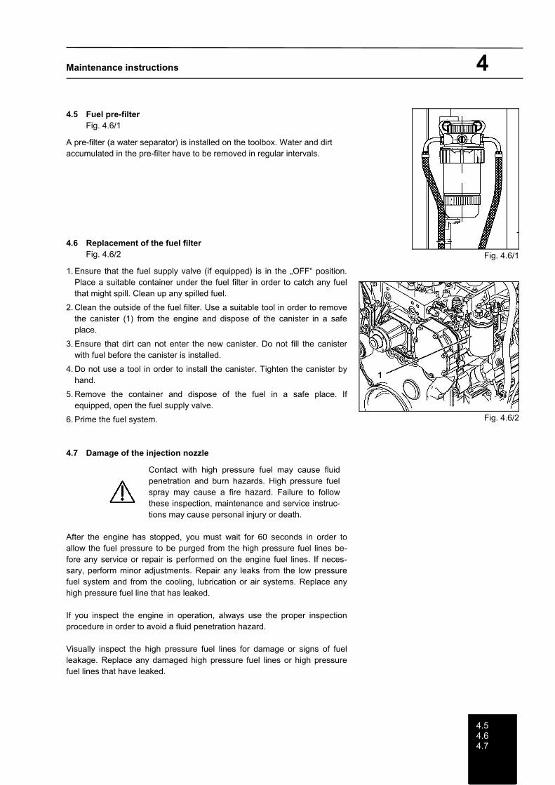
4.5 Fuel pre-filter Fig. 4.6/1
A pre-filter (a water separator) is installed on the toolbox. Water and dirt accumulated in the pre-filter have to be removed in regular intervals.
4.6 Replacement of the fuel filter Fig. 4.6/2
1. Ensure that the fuel supply valve (if equipped) is in the „OFF“ position. Place a suitable container under the fuel filter in order to catch any fuel that might spill. Clean up any spilled fuel.
2. Clean the outside of the fuel filter. Use a suitable tool in order to remove the canister (1) from the engine and dispose of the canister in a safe place.
3. Ensure that dirt can not enter the new canister. Do not fill the canister with fuel before the canister is installed.
4. Do not use a tool in order to install the canister. Tighten the canister by hand.
5. Remove the container and dispose of the fuel in a safe place. If equipped, open the fuel supply valve.
6. Prime the fuel system.
4.7 Damage of the injection nozzle
Contact with high pressure fuel may cause fluid penetration and burn hazards. High pressure fuel spray may cause a fire hazard. Failure to follow these inspection, maintenance and service instruc-tions may cause personal injury or death.
After the engine has stopped, you must wait for 60 seconds in order to allow the fuel pressure to be purged from the high pressure fuel lines be-fore any service or repair is performed on the engine fuel lines. If neces-sary, perform minor adjustments. Repair any leaks from the low pressure fuel system and from the cooling, lubrication or air systems. Replace any high pressure fuel line that has leaked.
If you inspect the engine in operation, always use the proper inspection procedure in order to avoid a fluid penetration hazard.
Visually inspect the high pressure fuel lines for damage or signs of fuel leakage. Replace any damaged high pressure fuel lines or high pressure fuel lines that have leaked.
Fig. 4.6/1
Fig. 4.6/2

Maintenance instructions 4
4.74.8
Ensure that all clips on the high pressure fuel lines are in place and that the clips are not loose.
- Inspect the rest of the fuel system for leaks. Look for loose fuel line clamps.
- Drain the water and the sediment from the fuel tank on a daily basis in order to ensure that only clean fuel enters the fuel system.
- Inspect the wiring and the wiring harnesses for loose connections and for worn wires or frayed wires. Check for any loose tie-wraps or mission tie-wraps.
- Inspect the ground strap for a good connection and for good condition.
- Disconnect any battery chargers that are not protected against the current drain of the starting motor. Check the condi-tion and the electrolyte level of the batteries, unless the engine is equipped with a maintenance free battery.
- Check the condition of the gauges. Replace any gauges that are cracked. Replace any gauge that can not be cali-brated.
4.8 Deaeration of the fuel system
If air enters the fuel system, the air must bee purged from the fuel system before the engine can bee started Air can enter the fuel system when the following events occur:
- The fuel tank is empty or the fuel tank has been partially drained.
- The low pressure fuel lines are disconnected.
- A leak exists in the low pressure fuel system.
- The fuel filter has been replaced.
Hand Fuel Priming Pump
Use the following procedures in order to remove air from the fuel system:
1. Ensure that the fuel system is in working order. Check that the fuel supply valve (if equipped) is in the “ON” position.
2. Operate the fuel priming pump. Count the number of operations of the fuel priming pump. After 100 depressions of the fuel priming pump stop.
3. The engine fuel system should now be primed and the engine should now be able to start.
4. Operate the engine starter and crank the engine. After the engine has started, operate the engine at low idle for a minimum of 5 minutes, immediately after air has been removed from the fuel system.
Note: Operating the engine for this period of time will help ensure that the fuel system is free of air.
Note: Do not loosen the high pressure fuel line in order to purge air from the fuel system. This procedure is not required.
After the engine has stopped, you must wait for 60 seconds in order to allow the fuel pressure to be purged from the high pressure fuel lines before any service or repair is performed on the engine fuel lines. If necessary, perform minor adjust-ments. Repair any leaks from the low pressure fuel system and from the cooling, lubrication or air systems. Replace any high pressure fuel line that has leaked.
If you inspect the engine in operation, always use the proper inspection procedure in order to avoid a fluid penetration hazard.
Maintenance instructions 4
4.94.10
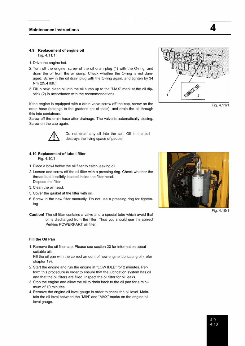
4.9 Replacement of engine oil Fig. 4.11/1
1. Drive the engine hot.
2. Turn off the engine, screw of the oil drain plug (1) with the O-ring, and drain the oil from the oil sump. Check whether the O-ring is not dam-aged. Screw in the oil drain plug with the O-ring again, and tighten by 34 Nm (25.4 lbft.).
3. Fill in new, clean oil into the oil sump up to the ”MAX” mark at the oil dip-stick (2) in accordance with the recommendations.
If the engine is equipped with a drain valve screw off the cap, screw on the drain hose (belongs to the grader’s set of tools), and drain the oil through this into containers. Screw off the drain hose after drainage. The valve is automatically closing. Screw on the cap again.
Do not drain any oil into the soil. Oil in the soil destroys the living space of people!
4.10 Replacement of luboil filter Fig. 4.10/1
1. Place a bowl below the oil filter to catch leaking oil.
2. Loosen and screw off the oil filter with a pressing ring. Check whether the thread butt is solidly located inside the filter head. Dispose the filter.
3. Clean the oil head.
5. Cover the gasket at the filter with oil.
6. Screw in the new filter manually. Do not use a pressing ring for tighten-ing.
Caution! The oil filter contains a valve and a special tube which avoid that oil is discharged from the filter. Thus you should use the correct Perkins POWERPART oil filter.
Fill the Oil Pan
1. Remove the oil filler cap. Please see section 20 for information about suitable oils. Fill the oil pan with the correct amount of new engine lubricating oil (refer chapter 19).
2. Start the engine and run the engine at “LOW IDLE” for 2 minutes. Per-form this procedure in order to ensure that the lubrication system has oil and that the oil filters are filled. Inspect the oil filter for oil leaks
3. Stop the engine and allow the oil to drain back to the oil pan for a mini-mum of 10 minutes.
4. Remove the engine oil level gauge in order to check the oil level. Main-tain the oil level between the “MIN” and “MAX” marks on the engine oil level gauge.
Fig. 4.11/1
Fig. 4.10/1
Maintenance instructions 4
4.11
4.11 Checking the valve clearance
Note: Only qualified service personal should perform this maintenance. Please contact your service agency for the com-plete procedure for setting the valve lash.
Operation of Perkins engines with incorrect valve lash can reduce engine efficiency, and also reduce engine component life.
Ensure that the engine can not be started while this maintenance is being performed. To help pre-vent possible injury, do not use the starting motor to turn the flywheel.
Hot engine components can cause burns. Allow additional time for the engine to cool before meas-uring/adjusting valve lash clearance.
Ensure that the engine is stopped before measuring the valve lash. The engine valve lash can bee inspected and ad-justed when the temperature of the engine is hot or cold.

Maintenance instructions 5
55.15.2
5 Cooling system
5.1 Check of coolant level Fig. 5/1
Put down the engine horizontally, and turn off the engine. Loosen the cover (D) of the cooler slowly and take it off.
When the engine is cold, the surface of the coolant must be level with the lower edge of the filler neck (water must always be visible). If required, add clean, soft water.
Let the engine run in low idle run for 2 - 3 minutes, afterwards. The control valve of the heating and ventilation system must be opened during this running (adjust to ”hot”). Check the coolant level once more, and add water, if required.
Note: The cooling system is filled with a long-time coolant for temperatures up to-37°C (-35°F). It consists of a mixture of water, anti-freeze, and anti-corrosion agents. The little losses by evaporation can be balanced with clean, soft water.
Be careful when opening the cover (D) of the cooler! Dan-ger of burning if the machine is hot!
When the machine is hot, loosen the cover of the cooler only to its first catch, and release the overpressure. Afterwards screw off the cover lid of the header tank, and take it off. Check the overpressure and underpressure valve of the cover lid. Replace any damaged or defective cover.
The cooling system should be checked before the beginning of the cold season, and should have a frost resistance of up to -20°C (-4°F). If lower temperatures are expected the portion of the anti-freeze has to be increased.
Note: At min. 80°C (176°F), the cooling system runs in the small circuit. The ther-mostat opens between 80 - 90°C (176 - 194°F). The complete opening is reached at 95°C (203°F). The heating system is connected to the small cir-cuit.
5.2 Replacement of coolant Fig. 5/2 and Fig. 5/3
Place the machine horizontally, and slowly loosen and remove the cover of the cooler. Open the drain cock (S) on the radiator, unscrew the drain plug (1) on the side of the cylinder block, and allow the coolant to drain. The drain hole must not be blocked. Afterwards flush the cooling system with cold water, when the engine is cold. Close all discharge openings Fill in coolant up to the lower edge of the filler neck into the cooler. Now let the engine run at lower idle run for 2 - 3 minutes, then check the coolant level again, and add coolant if required. Close the cooler.
Fig. 5/1
Fig. 5/2
Fig. 5/3

Maintenance instructions 5
5.3
5.3 External cleaning of the cooler
Open tailgate.
The cooler contaminated on its outside can be cleaned by a water jet or by compressed air.
Water should be sprayed and air blown through the radiator against the direction the fan is blowing.
Note: The cleaning with water can only be carried out when the engine has cooled down. Do not spray against the insulation material. The water pressure during cleaning must not exceed 275 hPa.

Maintenance instructions 6
66.1
6 Air filter system Fig. 6/1 and Fig. 6/2
The air filter is a combined air filter with an integrated filter-element (1) and a safety cartridge. The rough dust is discharged through the dust discharge valve (S), almost free of maintenance. The discharge slot of the valve must be checked for cleanness daily. Remove possible dust accumulations; move the valve slightly for that purpose. The rubber piece must be always well seated and lay on the bottom.
6.1 Air filter Fig. 6.1/1
The more the air filter insert is contaminated the higher becomes the un-derpressure in the suction line. If the extend of the contamination of the air filter insert becomes so high that the pressure drops below the permissible underpressure the warning lamp (1) in the cabin shines, and requests for the cleaning of the filter insert. To control the underpressure, an underpres-sure switch is installed in the suction line. It is adjusted to the permissible limit of underpressure.
The filter element has been cleaned. However, it has to be replaced not later than after the 6th cleaning or after 2,000 operating hours, at the lat-est. The control light expires to start the engine, after the cleaning of the filter element.
Notwithstanding the indication by the control lamps, the filter insert should be checked for its state from time to time. A damaged or deformed filter insert must be replaced immediately. The safety filter is replaced after every 3rd cleaning of the filter insert. It must not be cleaned.
The filter element must not be cleaned!
The maintenance of the air filter shall only be carried out with the engine switched off. The functioning of the indicator lamp in the cabin to check the filter must be checked every day, by operating the control switch (K). When the switch is operated, the control lamp (1) must shine.
6.1.1 Replacement, removal and insertion of the filter insert Fig. 6/1 and Fig. 6/2
The air filter is opened by a locking system (toggle fasteners A). Remove the air filter casing component after opening the toggle fasteners.The filter element (1) and safety cartridge (2) can now be removed, and cleaned or exchanged. Check the seal and its seating face in the filter casing. Check the seal on the filter cover. The filter insert and the safety cartridge are fitted in the reverse order to their disassembly.
Fig. 6/1
Fig. 6/2
Fig. 6.1/1
Maintenance instructions 6
6.1
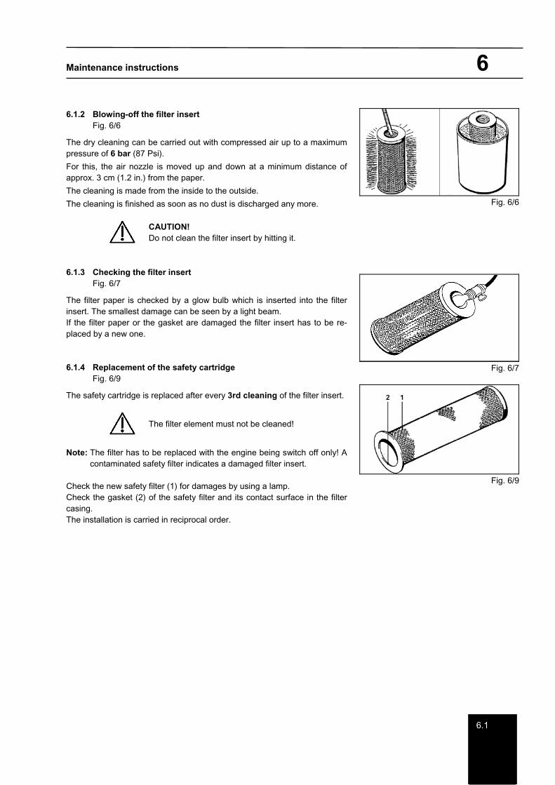
6.1.2 Blowing-off the filter insert Fig. 6/6
The dry cleaning can be carried out with compressed air up to a maximum pressure of 6 bar (87 Psi).
For this, the air nozzle is moved up and down at a minimum distance of approx. 3 cm (1.2 in.) from the paper.
The cleaning is made from the inside to the outside.
The cleaning is finished as soon as no dust is discharged any more.
CAUTION! Do not clean the filter insert by hitting it.
6.1.3 Checking the filter insert Fig. 6/7
The filter paper is checked by a glow bulb which is inserted into the filter insert. The smallest damage can be seen by a light beam. If the filter paper or the gasket are damaged the filter insert has to be re-placed by a new one.
6.1.4 Replacement of the safety cartridge Fig. 6/9
The safety cartridge is replaced after every 3rd cleaning of the filter insert.
The filter element must not be cleaned!
Note: The filter has to be replaced with the engine being switch off only! A contaminated safety filter indicates a damaged filter insert.
Check the new safety filter (1) for damages by using a lamp. Check the gasket (2) of the safety filter and its contact surface in the filter casing.The installation is carried in reciprocal order.
Fig. 6/6
Fig. 6/7
Fig. 6/9

Maintenance instructions 7
77.17.2
7 Powershift transmission / type 6 WG 115
Fig. 7/1 shows the schematic structure of the power shift gear.
For all activities at the gears, urgently comply with the prescribed safety regulations acc. to § 6 of the Regulation on the Prevention of Accidents at Propulsion Units. For example, the machine must be secured by wedges against rolling away, and articulated vehi-cles additionally against unintended turning (frame lockage).
Installation scheme 6 WG-115 1 = Oil dipstick 2 = Power take-off 3 = Electro hydraulic control 4 = Output 5 = Converter bell 6 = Oil drain 7 = Filter 8 = Parking brake
Fig. 7.1/1
7.1 Checking of oil level
Drive the machine hot (approx. 80 - 100°C/176 - 212°F). Place the machine horizontally. Shift to idle run of the engine., and put the gear shift lever to the neutral position (see for this ”Operation Manual”). Place chocks under the wheels to prevent the machine from rolling away, then tilt the cab (see "Operating Instructions", section 9.11).
The oil level must be at the upper mark at 80°C (176°F), and at the lower mark at 40°C (104°F) of the oil dip-stick.
When checking the oil level, insert the oil dip-stick into the oil-level tube completely.
If, at operating temperature, the oil level has fallen below the MIN range, it must be topped up with the appropriate oil (see section 21).
7.2 Replacement of oil
Place the machine horizontally. Turn of the engine, and shift the gear shift lever to the neutral position (see for this ”Op-eration Manual”). Secure the machine by wedges against rolling away.
Screw off the oil drain plugs , and drain the oil. Be careful during the drainage of the oil that only the oil quantity filled in the gears and in the upper part of the transformer can be drained through the oil drain plug. Afterwards strongly tighten the cleaned drain plug by applying a proper gasket.
Maintenance instructions 7
7.37.47.57.6
7.3 Oil filling
Take out the oil dip-stick, and fill in the prescribed oil through the opening for the oil dip-stick, until the oil level has reached the upper mark of the oil dip stick.
To fill the system let the engine run in idle run for a short time. Check the oil level as described above.
The quantity of oil to fill in is approx. 18 litres (approx. 4.75 USgal.). This value given is for orientation only. The mark on the oil dip-stick is binding in any case.
Only use approve oil brands!
7.4 Replacement of the filter
Turn off the engine. Drain the oil. Screw off the fixing screws of the filter casing cover and remove the filter casing cover. Replace the filter cartridge, and close the filter casing with the cover.
The filter cartridge has to be replaced during every replacement of oil! Only use original spare parts!
7.5 Handling of the filter
Handle the filter with care during installation, transport, and storage!. Dam-aged filter must not be used or installed!
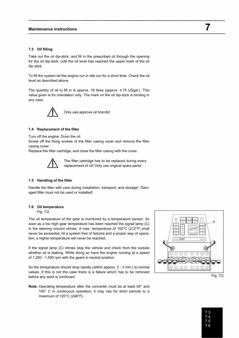
7.6 Oil temperature Fig. 7/2
The oil temperature of the gear is monitored by a temperature sensor. As soon as a too high gear temperature has been reached the signal lamp (C) in the steering column shines. A max. temperature of 100°C (212°F) shall never be exceeded. At a system free of failures and a proper way of opera-tion, a higher temperature will never be reached.
If the signal lamp (C) shines stop the vehicle and check from the outside whether oil is leaking. While doing so have the engine running at a speed of 1,200 - 1,500 rpm with the gears in neutral position.
So the temperature should drop rapidly (within approx. 2 - 3 min.) to normal values. If this is not the case there is a failure which has to be removed before any work is continued.
Note: Operating temperature after the converter must be at least 65° and 100° C in continuous operation, it may rise for short periods to a maximum of 120°C (248°F).
Fig. 7/2
Maintenance instructions 8
8
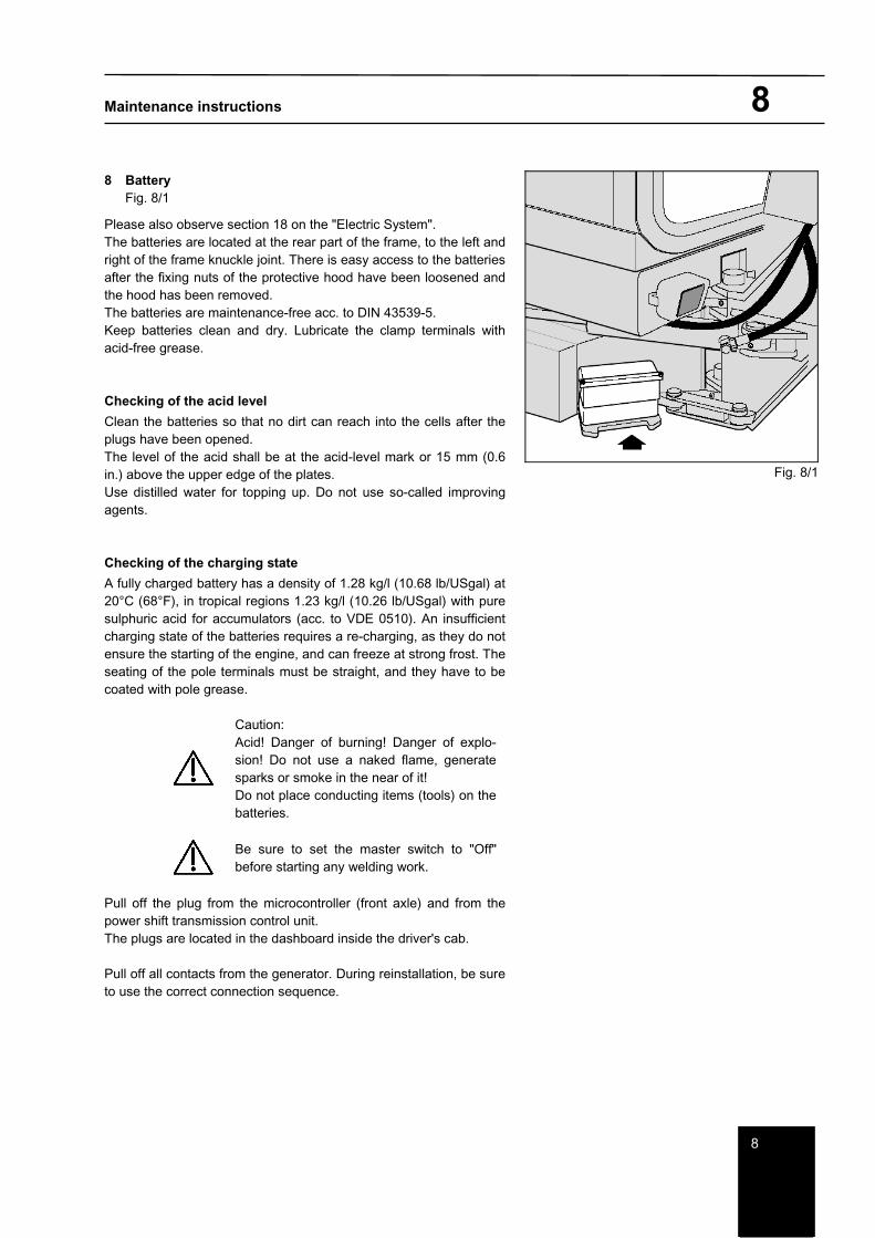
8 Battery Fig. 8/1
Please also observe section 18 on the "Electric System". The batteries are located at the rear part of the frame, to the left and right of the frame knuckle joint. There is easy access to the batteries after the fixing nuts of the protective hood have been loosened and the hood has been removed. The batteries are maintenance-free acc. to DIN 43539-5. Keep batteries clean and dry. Lubricate the clamp terminals with acid-free grease.
Checking of the acid level
Clean the batteries so that no dirt can reach into the cells after the plugs have been opened. The level of the acid shall be at the acid-level mark or 15 mm (0.6 in.) above the upper edge of the plates. Use distilled water for topping up. Do not use so-called improving agents.
Checking of the charging state
A fully charged battery has a density of 1.28 kg/l (10.68 lb/USgal) at 20°C (68°F), in tropical regions 1.23 kg/l (10.26 lb/USgal) with pure sulphuric acid for accumulators (acc. to VDE 0510). An insufficient charging state of the batteries requires a re-charging, as they do not ensure the starting of the engine, and can freeze at strong frost. The seating of the pole terminals must be straight, and they have to be coated with pole grease.
Caution: Acid! Danger of burning! Danger of explo-sion! Do not use a naked flame, generate sparks or smoke in the near of it! Do not place conducting items (tools) on the batteries.
Be sure to set the master switch to "Off" before starting any welding work.
Pull off the plug from the microcontroller (front axle) and from the power shift transmission control unit. The plugs are located in the dashboard inside the driver's cab.
Pull off all contacts from the generator. During reinstallation, be sure to use the correct connection sequence.
Fig. 8/1

Maintenance instructions 9
99.19.2
9 Rear axle
During welding, the (-) pole of the welding transformer shall not connected to the rear axle.
Any welding at the rear axle is not permitted!
9.1 Checking of oil levels
Checking of the oil level in the axle gear Fig. 9/1
Place the machine horizontally. Turn off the engine. Slowly screw off the control screw (K). The oil level has to be at the lower edge of the control boring. If required, add oil.
Checking of the oil level in the tandems Fig. 9/2
The oil level is indicated at the control eye (K). The oil level shall fill half of the eye. If required, add oil.
Checking of the oil level in the wheel hubs (planetary gears) Fig. 9/3
By moving the machine, put the wheel hub to check to a position that the mark line ”oil level” of the screw cap (K) is horizontal. The oil level must be at the lower edge of the boring. If required, add oil.
9.2 Replacement of oil at the rear axle
Generally replace the oil in hot state. For this, place the machine horizontally. Do not allow any oil to penetrate into the ground. Oil catching containers have to be generally used. During each replacement of oil, replace the gaskets of the drain plugs too.
Oil in the soil destroys the habitat of the people!
Replacement of oil at the axle gear Fig. 9/1 and Fig. 9/4
Screw off the drain plug (A) and the fill-in plug with the deaerator (E), discharge the oil into a container. Close the drain plug, and fill in oil. The oil filling opening can be easily reached from the left of the engine room (fig. 9/4). Check the oil level, and close the fill-in plug and the control screw.
Fig. 9/1
Fig. 9/2
Fig. 9/3
Fig. 9/4
Maintenance instructions 9
9.2
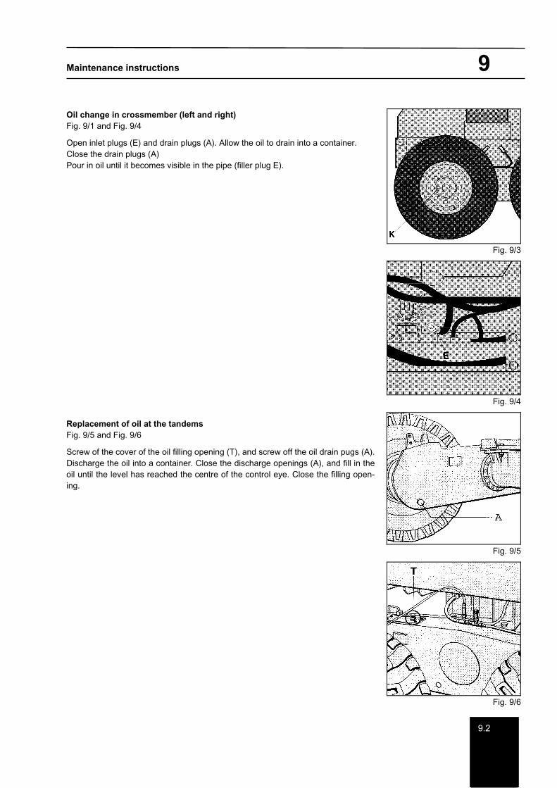
Oil change in crossmember (left and right) Fig. 9/1 and Fig. 9/4
Open inlet plugs (E) and drain plugs (A). Allow the oil to drain into a container. Close the drain plugs (A) Pour in oil until it becomes visible in the pipe (filler plug E).
Replacement of oil at the tandems Fig. 9/5 and Fig. 9/6
Screw of the cover of the oil filling opening (T), and screw off the oil drain pugs (A). Discharge the oil into a container. Close the discharge openings (A), and fill in the oil until the level has reached the centre of the control eye. Close the filling open-ing.
Fig. 9/3
Fig. 9/4
Fig. 9/5
Fig. 9/6
Maintenance instructions 9
9.2
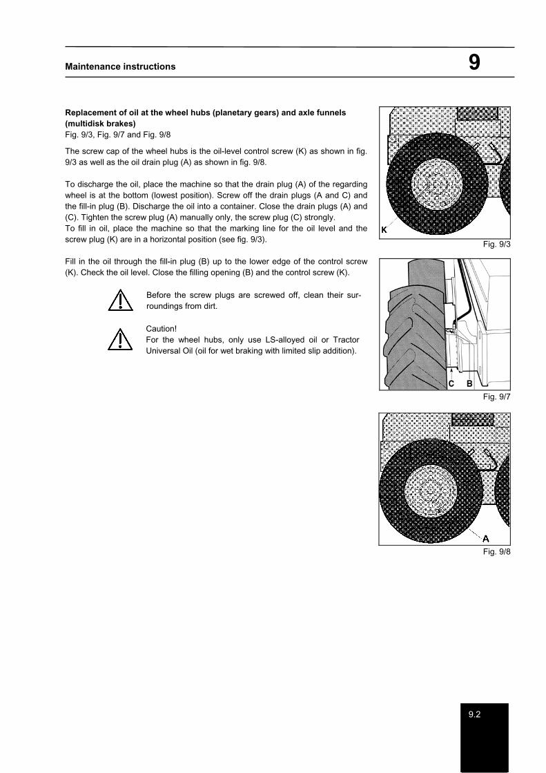
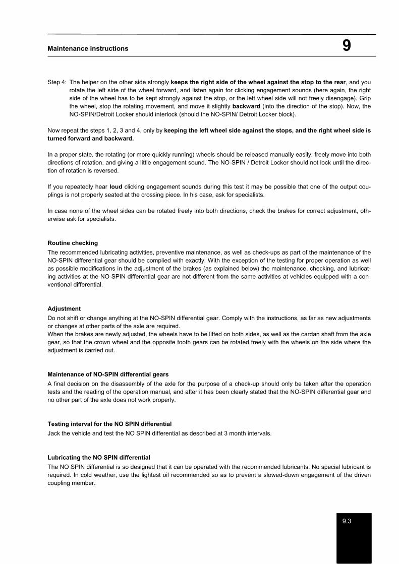
Replacement of oil at the wheel hubs (planetary gears) and axle funnels (multidisk brakes) Fig. 9/3, Fig. 9/7 and Fig. 9/8
The screw cap of the wheel hubs is the oil-level control screw (K) as shown in fig. 9/3 as well as the oil drain plug (A) as shown in fig. 9/8.
To discharge the oil, place the machine so that the drain plug (A) of the regarding wheel is at the bottom (lowest position). Screw off the drain plugs (A and C) and the fill-in plug (B). Discharge the oil into a container. Close the drain plugs (A) and (C). Tighten the screw plug (A) manually only, the screw plug (C) strongly. To fill in oil, place the machine so that the marking line for the oil level and the screw plug (K) are in a horizontal position (see fig. 9/3).
Fill in the oil through the fill-in plug (B) up to the lower edge of the control screw (K). Check the oil level. Close the filling opening (B) and the control screw (K).
Before the screw plugs are screwed off, clean their sur-roundings from dirt.
Caution! For the wheel hubs, only use LS-alloyed oil or Tractor Universal Oil (oil for wet braking with limited slip addition).
Fig. 9/3
Fig. 9/7
Fig. 9/8
Maintenance instructions 9
9.3
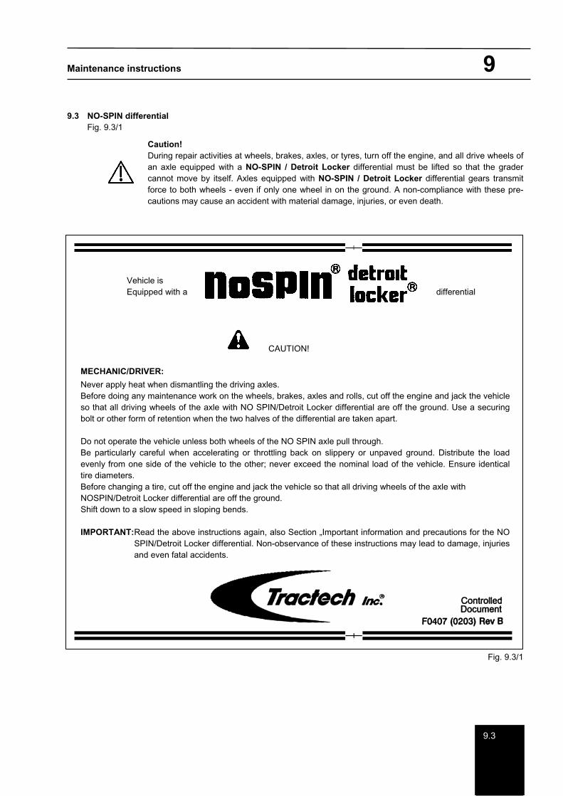
9.3 NO-SPIN differential Fig. 9.3/1
Caution! During repair activities at wheels, brakes, axles, or tyres, turn off the engine, and all drive wheels of an axle equipped with a NO-SPIN / Detroit Locker differential must be lifted so that the grader cannot move by itself. Axles equipped with NO-SPIN / Detroit Locker differential gears transmit force to both wheels - even if only one wheel in on the ground. A non-compliance with these pre-cautions may cause an accident with material damage, injuries, or even death.
Vehicle is Equipped with a differential
CAUTION!
MECHANIC/DRIVER:
Never apply heat when dismantling the driving axles. Before doing any maintenance work on the wheels, brakes, axles and rolls, cut off the engine and jack the vehicle so that all driving wheels of the axle with NO SPIN/Detroit Locker differential are off the ground. Use a securing bolt or other form of retention when the two halves of the differential are taken apart.
Do not operate the vehicle unless both wheels of the NO SPIN axle pull through. Be particularly careful when accelerating or throttling back on slippery or unpaved ground. Distribute the load evenly from one side of the vehicle to the other; never exceed the nominal load of the vehicle. Ensure identical tire diameters. Before changing a tire, cut off the engine and jack the vehicle so that all driving wheels of the axle with NOSPIN/Detroit Locker differential are off the ground. Shift down to a slow speed in sloping bends.
IMPORTANT:Read the above instructions again, also Section „Important information and precautions for the NO SPIN/Detroit Locker differential. Non-observance of these instructions may lead to damage, injuries and even fatal accidents.
Fig. 9.3/1

Maintenance instructions 9
9.3
Checking of the NO-SPIN differential during driving
If a permanent ticking can be heard when driving straight forward, or if a permanent pulling to the right or left is stated during forward driving, so e.g. the roll-on radius of the tyres could be the reason because of irregular wear or different tyre pressures (possibly correct tyre pressure, and measure the distance between the ground and the rim. During an alternating acceleration and braking when driving through a curve, it is possible that a snapping sound can be heard sometimes, when the torque changes from ”drive torque at the inner wheels” to the ”braking torque at the outer wheels”.
Functional test
Make sure that both wheel pairs of the axle equipped with a NO-SPIN differential gears have tensile force. Carry out this test under load so that the torque of the engine is acting on the wheels standing on the drive lane, through the NO-SPIN differential. This kind of load can be reached by driving a solid obstruction (on an unpaved or crushed-stone lane), and trying to spin the wheels together. Carry out this test in forward as well as backward movement.
Utmost care is required when this test is carried out to avoid any damages at the grader and at the obstruction used.
Checking the disengagement process
Drive in forward and reverse gear in a small circle on a flat road with good traction properties to ensure that the outer wheel pairs can turn faster freely (i.e., that the outer tyres do not "grind"). You will mostly hear a clicking disengagement sound. A gear engagement sound may also be heard when the curve is complete. This is absolutely normal.
Hint:Tractech issued an operation and repair manual for the NO-SPIN differential gear (Issue No. 1014). The instruc-tions given therein are a useful support for owners and users of vehicles equipped with NO-SPIN Detroit Locker dif-ferential gears when searching for and solving problems with regard to capacity. For graders equipped with NO-SPIN differentials, the above mentioned manual is attached to the operation manual.
Checking of the NO-SPIN differential for proper operation when the machine stands
Series of activities: Secure the machine against rolling away. Lift the NO-SPIN axle so that both wheel pairs do no longer touch the ground. Engage the parking brake. Disconnect the flange of the cardan shaft from the rear axle.
Step 1: Start the test in such a way that a helper stands on the opposite side who, together with you, rotates the wheel in forward direction, namely as far as possible (after a short rotation, the wheels should not allow a turning any more).
Step 2: During a helper keeps the right side of the wheel strongly in forward direction (against the stop), rotate the left side of the wheel backward, and listen to a clicking engagement sound, at the same time (the right wheel side must be kept against the stop, or the left side of the wheel does not disengage freely). Now grip the left side of the wheel and stop its rotating movement, then move it to the front ( into the direction of the stop). The NO-SPIN differential gear should interlock now.
Step 3: Rotate both wheel sides backward as far as possible (both wheel sides should stop after a short rotating move-ment.)
Maintenance instructions 9
9.3
Step 4: The helper on the other side strongly keeps the right side of the wheel against the stop to the rear, and you rotate the left side of the wheel forward, and listen again for clicking engagement sounds (here again, the right side of the wheel has to be kept strongly against the stop, or the left wheel side will not freely disengage). Grip the wheel, stop the rotating movement, and move it slightly backward (into the direction of the stop). Now, the NO-SPIN/Detroit Locker should interlock (should the NO-SPIN/ Detroit Locker block).
Now repeat the steps 1, 2, 3 and 4, only by keeping the left wheel side against the stops, and the right wheel side is turned forward and backward.
In a proper state, the rotating (or more quickly running) wheels should be released manually easily, freely move into both directions of rotation, and giving a little engagement sound. The NO-SPIN / Detroit Locker should not lock until the direc-tion of rotation is reversed.
If you repeatedly hear loud clicking engagement sounds during this test it may be possible that one of the output cou-plings is not properly seated at the crossing piece. In his case, ask for specialists.
In case none of the wheel sides can be rotated freely into both directions, check the brakes for correct adjustment, oth-erwise ask for specialists.
Routine checking
The recommended lubricating activities, preventive maintenance, as well as check-ups as part of the maintenance of the NO-SPIN differential gear should be complied with exactly. With the exception of the testing for proper operation as well as possible modifications in the adjustment of the brakes (as explained below) the maintenance, checking, and lubricat-ing activities at the NO-SPIN differential gear are not different from the same activities at vehicles equipped with a con-ventional differential.
Adjustment
Do not shift or change anything at the NO-SPIN differential gear. Comply with the instructions, as far as new adjustments or changes at other parts of the axle are required. When the brakes are newly adjusted, the wheels have to be lifted on both sides, as well as the cardan shaft from the axle gear, so that the crown wheel and the opposite tooth gears can be rotated freely with the wheels on the side where the adjustment is carried out.
Maintenance of NO-SPIN differential gears
A final decision on the disassembly of the axle for the purpose of a check-up should only be taken after the operation tests and the reading of the operation manual, and after it has been clearly stated that the NO-SPIN differential gear and no other part of the axle does not work properly.
Testing interval for the NO SPIN differential
Jack the vehicle and test the NO SPIN differential as described at 3 month intervals.
Lubricating the NO SPIN differential
The NO SPIN differential is so designed that it can be operated with the recommended lubricants. No special lubricant is required. In cold weather, use the lightest oil recommended so as to prevent a slowed-down engagement of the driven coupling member.
Maintenance instructions 9
9.39.4
Important recommendations for the driver
Drive the vehicle only when the two wheel pairs of the NO SPIN axle are firmly on the ground. Power transmission to one wheel pair only may entail steering problems. Be particularly careful when accelerating and braking with the engine on a slippery or unpaved road. Machines equipped with self-locking differentials tend to skid. See to it that the tires on the wheels of the NO SPIN axle have the same diameter. Diameter differences may lead to different speeds of the wheel pairs; as a consequence, the differential may transmit the torque to one wheel pair only (steering problems).
Before changing a tire of a NO SPIN axle wheel, cut off the engine and lift the wheel pairs on both sides off the ground so that the machine cannot roll away. Axles with NO SPIN differentials will also transmit the torque to both wheel pairs when only one wheel pair has ground contact. When driving a machine with a NO SPIN differential down a sloping bend, the braking effect of the engine or retarder is restricted.
Very important! Non-observance of this may lead to component failures or accidents (damage, injuries or death).
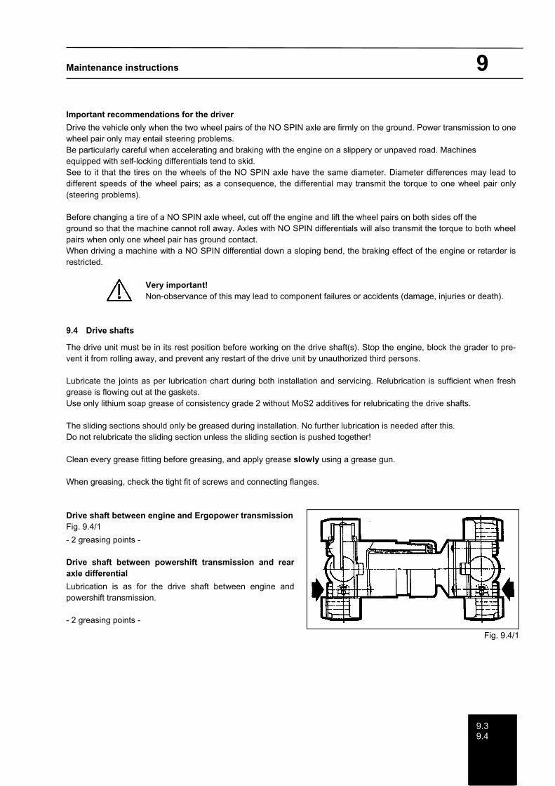
9.4 Drive shafts
The drive unit must be in its rest position before working on the drive shaft(s). Stop the engine, block the grader to pre-vent it from rolling away, and prevent any restart of the drive unit by unauthorized third persons.
Lubricate the joints as per lubrication chart during both installation and servicing. Relubrication is sufficient when fresh grease is flowing out at the gaskets. Use only lithium soap grease of consistency grade 2 without MoS2 additives for relubricating the drive shafts.
The sliding sections should only be greased during installation. No further lubrication is needed after this. Do not relubricate the sliding section unless the sliding section is pushed together!
Clean every grease fitting before greasing, and apply grease slowly using a grease gun.
When greasing, check the tight fit of screws and connecting flanges.
Drive shaft between engine and Ergopower transmissionFig. 9.4/1
- 2 greasing points -
Drive shaft between powershift transmission and rear axle differential
Lubrication is as for the drive shaft between engine and powershift transmission.
- 2 greasing points -
Fig. 9.4/1

Maintenance instructions 10
10
10 Front axle Fig.10/1
The following points are to be greased at the intervals shown in the maintenance plan:
King pins (1) - 4 lubrication points Axle (2) - 2 lubrication points Tipping cylinder (3) - 2 lubrication points Axles (4) - 4 lubrication points Hubs (5) - 2 lubrication points
Clean the lubricating nipple thoroughly before regreasing.
Wheel bearings
The grease level in the grease compartment of the wheel bearing must be checked after the number of operating hours shown in the maintenance plan, but in any case at least every two years. The covers must be unscrewed to do this. The grease compartment must be about 2/3 full with grease. The grease must be topped up as and when necessary.
When checking the grease fill in the wheel bearings, you should also check the wheel bearing clearance (tapered roller bearing), and readjust this clearance as follows. Tighten the tapered roller bearings with the slotted round nut against one another until no further rotation by hand is possible. Turn back the slotted round nut until the hub can be rotated freely (approx. 1/12 turn), and lock using a tab washer. Lock using both the 2nd slotted round nut and Loctite 648. Check whether the hub runs without stoppage and without tilting clearance. The wheel bearing must be readjusted when the front axle is lifted, i.e. when the wheels do not touch the ground.
Fig. 10/1

Maintenance instructions 11
1111.1
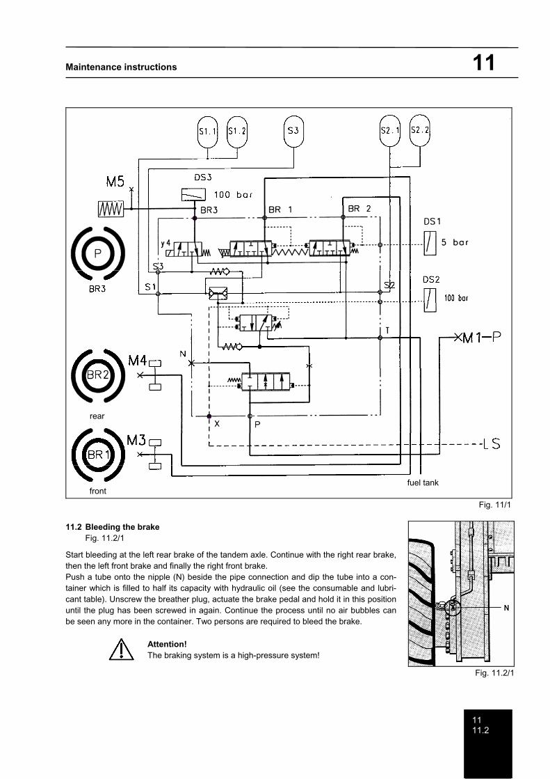
11 Braking system Fig. 11/1
The diagram of the operating brake system is shown in fig. 11/1. There is no specific maintenance obligation for the braking system.
Keep the whole system clean, and check it for leaks in compliance with the inspection schedule.
Four measuring points are provided for check measurements:
M1 = Storage pressure M3 = Service brake pressure M4 = Service brake pressure M5 = Parking brake release pressure
Location of measuring points:
M1 = Right-hand control block output M3 = Right-hand inside rear frame part (in the tandem rocker area) M4 = Right-hand inside rear frame part (in the tandem rocker area) M5 = Cab floor at the accumulator; connection BR3
Measured values:
M1 = Filled accumulators 24 bars during storage loading (short time) 123 - 150 bar (TG 110, 150, 190)
M3 = 90 - 3 bar M4 = 90 - 3 bar M5 = 123 - 150 bar (TG 110, 150, 190)
The complete brake valve will need to be changed when a fault occurs in the brake system. The repair or modification of braking valves by unauthorised personnel is not permitted.
Caution! Maintenance and repair activities at the braking system shall be carried out by a specialist only, the safety regulations must be complied with. The tanks of the braking system are exposed to high pressure. Before lines are disconnected or before any other work at the hydraulic brake, the pressure in the pedal braking system must be reduced by pressing the brake pedal for 15 times, at least, with the engine turned off.
11.1 Parking brake
The parking brake is maintenance-free. It has to be checked for the wear of the brake lining in accordance with the main-tenance and inspection schedule. The brake needs to be adjusted when the air gap is greater than 1.5 mm. Replace the brake lining if no further adjustment is possible.
Maintenance instructions 11
1111.2
Fig. 11/1
11.2 Bleeding the brake Fig. 11.2/1
Start bleeding at the left rear brake of the tandem axle. Continue with the right rear brake, then the left front brake and finally the right front brake. Push a tube onto the nipple (N) beside the pipe connection and dip the tube into a con-tainer which is filled to half its capacity with hydraulic oil (see the consumable and lubri-cant table). Unscrew the breather plug, actuate the brake pedal and hold it in this position until the plug has been screwed in again. Continue the process until no air bubbles can be seen any more in the container. Two persons are required to bleed the brake.
Attention! The braking system is a high-pressure system!
Fig. 11.2/1
rear
front fuel tank
Maintenance instructions 11
11.3
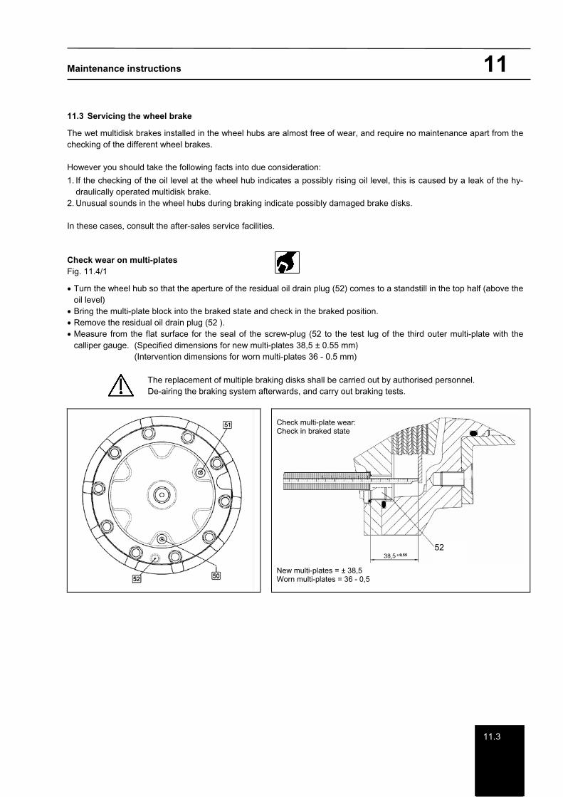
11.3 Servicing the wheel brake
The wet multidisk brakes installed in the wheel hubs are almost free of wear, and require no maintenance apart from the checking of the different wheel brakes.
However you should take the following facts into due consideration:
1. If the checking of the oil level at the wheel hub indicates a possibly rising oil level, this is caused by a leak of the hy-draulically operated multidisk brake.
2. Unusual sounds in the wheel hubs during braking indicate possibly damaged brake disks.
In these cases, consult the after-sales service facilities.
Check wear on multi-plates Fig. 11.4/1
Turn the wheel hub so that the aperture of the residual oil drain plug (52) comes to a standstill in the top half (above the oil level)
Bring the multi-plate block into the braked state and check in the braked position. Remove the residual oil drain plug (52 ). Measure from the flat surface for the seal of the screw-plug (52 to the test lug of the third outer multi-plate with the calliper gauge. (Specified dimensions for new multi-plates 38,5 ± 0.55 mm) (Intervention dimensions for worn multi-plates 36 - 0.5 mm)
The replacement of multiple braking disks shall be carried out by authorised personnel. De-airing the braking system afterwards, and carry out braking tests.
Check multi-plate wear: Check in braked state
New multi-plates = ± 38,5 Worn multi-plates = 36 - 0,5
52
Maintenance instructions 11
11.4
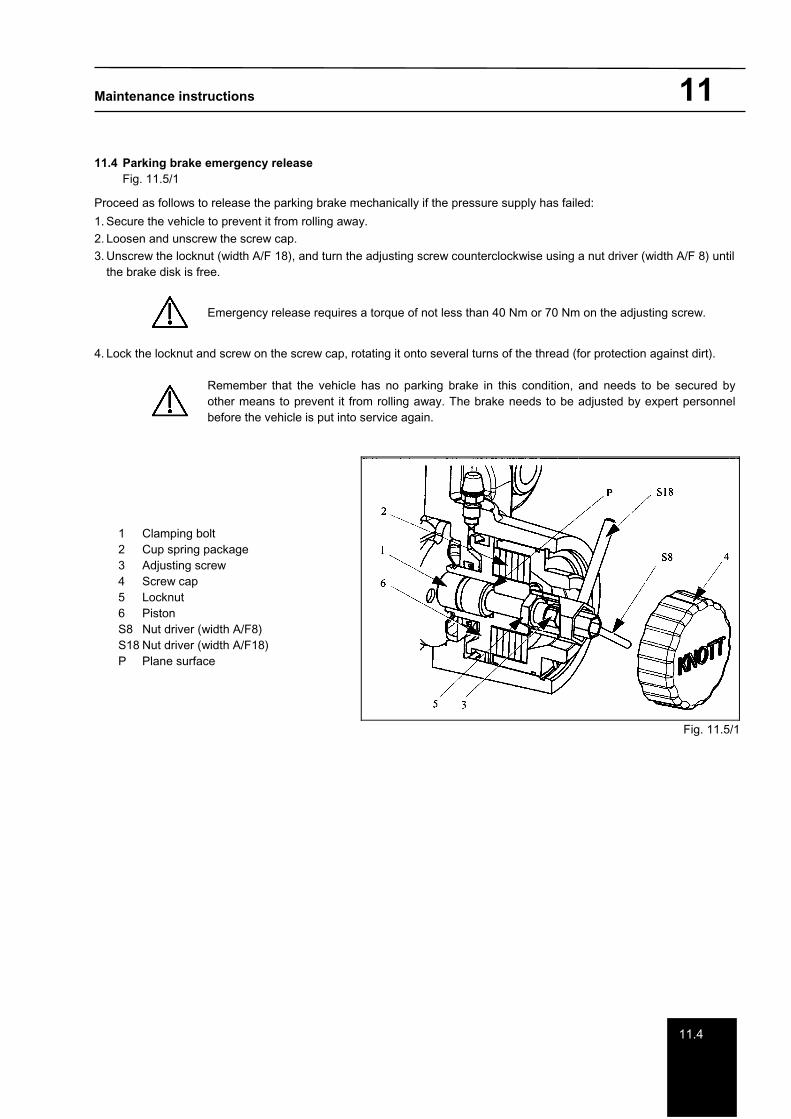
11.4 Parking brake emergency release Fig. 11.5/1
Proceed as follows to release the parking brake mechanically if the pressure supply has failed:
1. Secure the vehicle to prevent it from rolling away. 2. Loosen and unscrew the screw cap. 3. Unscrew the locknut (width A/F 18), and turn the adjusting screw counterclockwise using a nut driver (width A/F 8) until
the brake disk is free.
Emergency release requires a torque of not less than 40 Nm or 70 Nm on the adjusting screw.
4. Lock the locknut and screw on the screw cap, rotating it onto several turns of the thread (for protection against dirt).
Remember that the vehicle has no parking brake in this condition, and needs to be secured by other means to prevent it from rolling away. The brake needs to be adjusted by expert personnel before the vehicle is put into service again.
1 Clamping bolt 2 Cup spring package 3 Adjusting screw 4 Screw cap 5 Locknut 6 Piston S8 Nut driver (width A/F8) S18 Nut driver (width A/F18) P Plane surface
Fig. 11.5/1
Maintenance instructions 12
1212.1
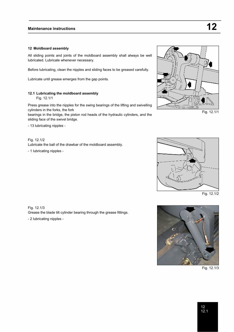
12 Moldboard assembly
All sliding points and joints of the moldboard assembly shall always be well lubricated. Lubricate whenever necessary.
Before lubricating, clean the nipples and sliding faces to be greased carefully.
Lubricate until grease emerges from the gap points.
12.1 Lubricating the moldboard assembly Fig. 12.1/1
Press grease into the nipples for the swing bearings of the lifting and swivelling cylinders in the forks, the fork bearings in the bridge, the piston rod heads of the hydraulic cylinders, and the sliding face of the swivel bridge.
- 13 lubricating nipples -
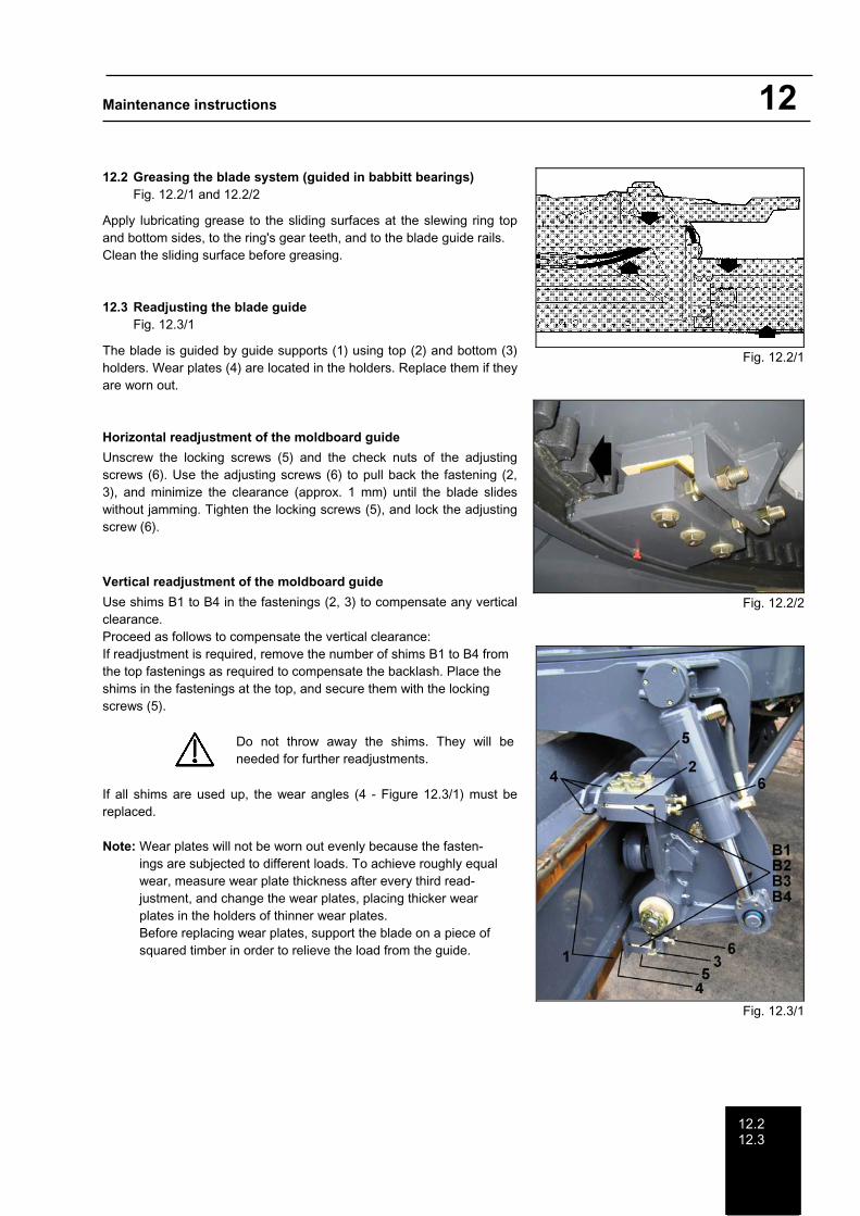
Fig. 12.1/2 Lubricate the ball of the drawbar of the moldboard assembly.
- 1 lubricating nipples -
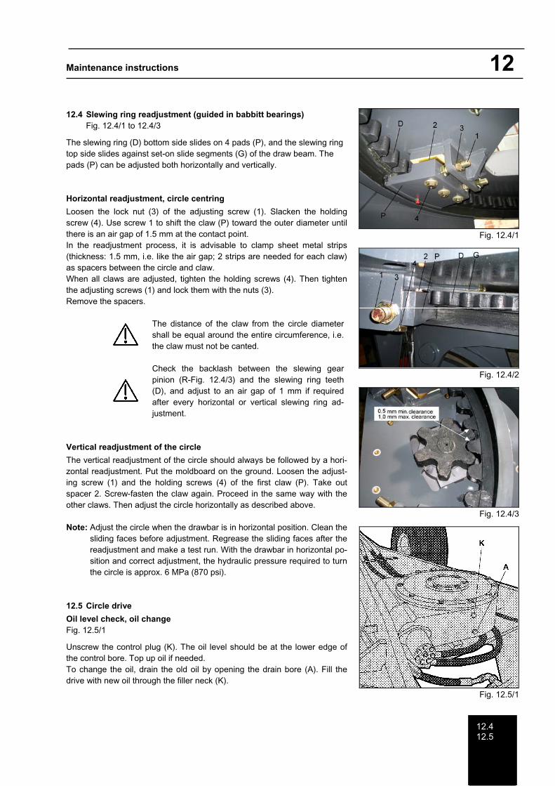
Fig. 12.1/3 Grease the blade tilt cylinder bearing through the grease fittings.
- 2 lubricating nipples -
Fig. 12.1/1
Fig. 12.1/2
Fig. 12.1/3
Maintenance instructions 12
12.212.3
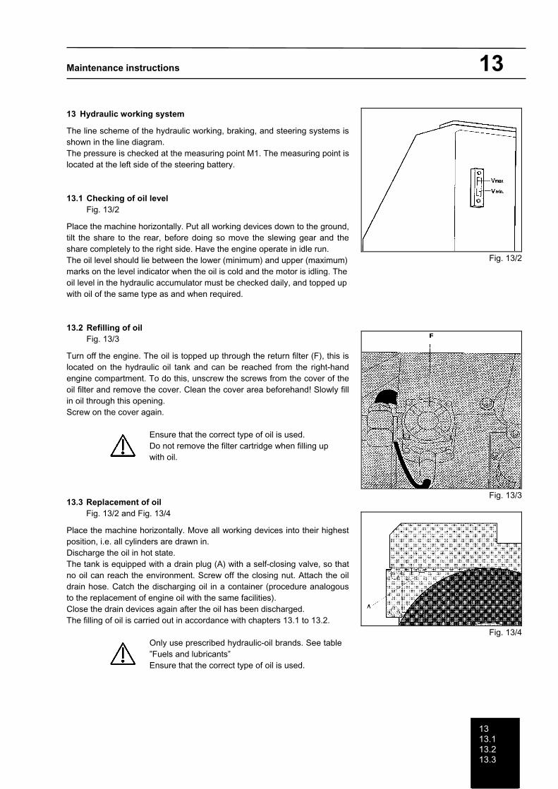
12.2 Greasing the blade system (guided in babbitt bearings) Fig. 12.2/1 and 12.2/2
Apply lubricating grease to the sliding surfaces at the slewing ring top and bottom sides, to the ring's gear teeth, and to the blade guide rails. Clean the sliding surface before greasing.
12.3 Readjusting the blade guide Fig. 12.3/1
The blade is guided by guide supports (1) using top (2) and bottom (3) holders. Wear plates (4) are located in the holders. Replace them if they are worn out.
Horizontal readjustment of the moldboard guide
Unscrew the locking screws (5) and the check nuts of the adjusting screws (6). Use the adjusting screws (6) to pull back the fastening (2, 3), and minimize the clearance (approx. 1 mm) until the blade slides without jamming. Tighten the locking screws (5), and lock the adjusting screw (6).
Vertical readjustment of the moldboard guide
Use shims B1 to B4 in the fastenings (2, 3) to compensate any vertical clearance. Proceed as follows to compensate the vertical clearance: If readjustment is required, remove the number of shims B1 to B4 from the top fastenings as required to compensate the backlash. Place the shims in the fastenings at the top, and secure them with the locking screws (5).
Do not throw away the shims. They will be needed for further readjustments.
If all shims are used up, the wear angles (4 - Figure 12.3/1) must be replaced.
Note: Wear plates will not be worn out evenly because the fasten-ings are subjected to different loads. To achieve roughly equal wear, measure wear plate thickness after every third read-justment, and change the wear plates, placing thicker wear plates in the holders of thinner wear plates. Before replacing wear plates, support the blade on a piece of squared timber in order to relieve the load from the guide.
Fig. 12.2/1
Fig. 12.2/2
Fig. 12.3/1
Maintenance instructions 12
12.412.5
12.4 Slewing ring readjustment (guided in babbitt bearings) Fig. 12.4/1 to 12.4/3
The slewing ring (D) bottom side slides on 4 pads (P), and the slewing ring top side slides against set-on slide segments (G) of the draw beam. The pads (P) can be adjusted both horizontally and vertically.
Horizontal readjustment, circle centring
Loosen the lock nut (3) of the adjusting screw (1). Slacken the holding screw (4). Use screw 1 to shift the claw (P) toward the outer diameter until there is an air gap of 1.5 mm at the contact point. In the readjustment process, it is advisable to clamp sheet metal strips (thickness: 1.5 mm, i.e. like the air gap; 2 strips are needed for each claw) as spacers between the circle and claw. When all claws are adjusted, tighten the holding screws (4). Then tighten the adjusting screws (1) and lock them with the nuts (3). Remove the spacers.
The distance of the claw from the circle diameter shall be equal around the entire circumference, i.e. the claw must not be canted.
Check the backlash between the slewing gear pinion (R-Fig. 12.4/3) and the slewing ring teeth (D), and adjust to an air gap of 1 mm if required after every horizontal or vertical slewing ring ad-justment.
Vertical readjustment of the circle
The vertical readjustment of the circle should always be followed by a hori-zontal readjustment. Put the moldboard on the ground. Loosen the adjust-ing screw (1) and the holding screws (4) of the first claw (P). Take out spacer 2. Screw-fasten the claw again. Proceed in the same way with the other claws. Then adjust the circle horizontally as described above.
Note: Adjust the circle when the drawbar is in horizontal position. Clean the sliding faces before adjustment. Regrease the sliding faces after the readjustment and make a test run. With the drawbar in horizontal po-sition and correct adjustment, the hydraulic pressure required to turn the circle is approx. 6 MPa (870 psi).
12.5 Circle drive
Oil level check, oil change Fig. 12.5/1
Unscrew the control plug (K). The oil level should be at the lower edge of the control bore. Top up oil if needed. To change the oil, drain the old oil by opening the drain bore (A). Fill the drive with new oil through the filler neck (K).
Fig. 12.4/1
Fig. 12.4/2
Fig. 12.4/3
Fig. 12.5/1
Maintenance instructions 13
1313.113.213.3
13 Hydraulic working system
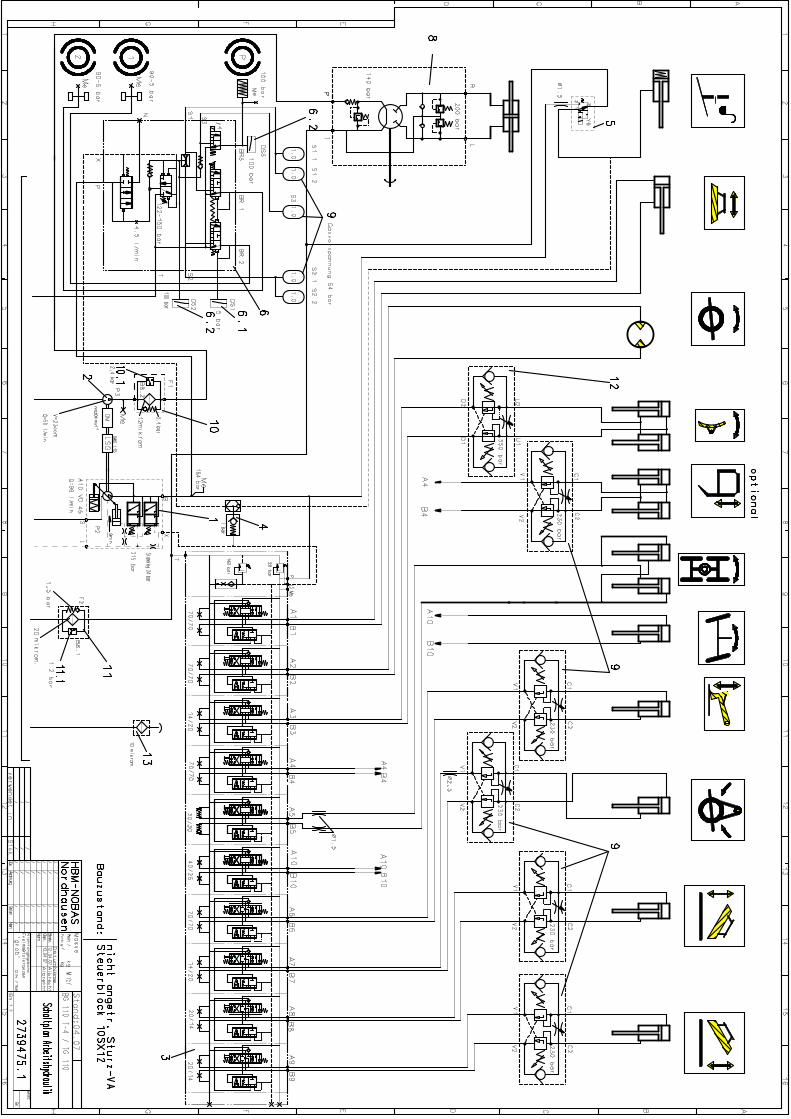
The line scheme of the hydraulic working, braking, and steering systems is shown in the line diagram. The pressure is checked at the measuring point M1. The measuring point is located at the left side of the steering battery.
13.1 Checking of oil level Fig. 13/2
Place the machine horizontally. Put all working devices down to the ground, tilt the share to the rear, before doing so move the slewing gear and the share completely to the right side. Have the engine operate in idle run. The oil level should lie between the lower (minimum) and upper (maximum) marks on the level indicator when the oil is cold and the motor is idling. The oil level in the hydraulic accumulator must be checked daily, and topped up with oil of the same type as and when required.
13.2 Refilling of oil Fig. 13/3
Turn off the engine. The oil is topped up through the return filter (F), this is located on the hydraulic oil tank and can be reached from the right-hand engine compartment. To do this, unscrew the screws from the cover of the oil filter and remove the cover. Clean the cover area beforehand! Slowly fill in oil through this opening. Screw on the cover again.
Ensure that the correct type of oil is used. Do not remove the filter cartridge when filling up with oil.
13.3 Replacement of oil Fig. 13/2 and Fig. 13/4
Place the machine horizontally. Move all working devices into their highest position, i.e. all cylinders are drawn in. Discharge the oil in hot state. The tank is equipped with a drain plug (A) with a self-closing valve, so that no oil can reach the environment. Screw off the closing nut. Attach the oil drain hose. Catch the discharging oil in a container (procedure analogous to the replacement of engine oil with the same facilities). Close the drain devices again after the oil has been discharged. The filling of oil is carried out in accordance with chapters 13.1 to 13.2.
Only use prescribed hydraulic-oil brands. See table ”Fuels and lubricants” Ensure that the correct type of oil is used.
Fig. 13/2
Fig. 13/3
Fig. 13/4
Maintenance instructions 13
13.4
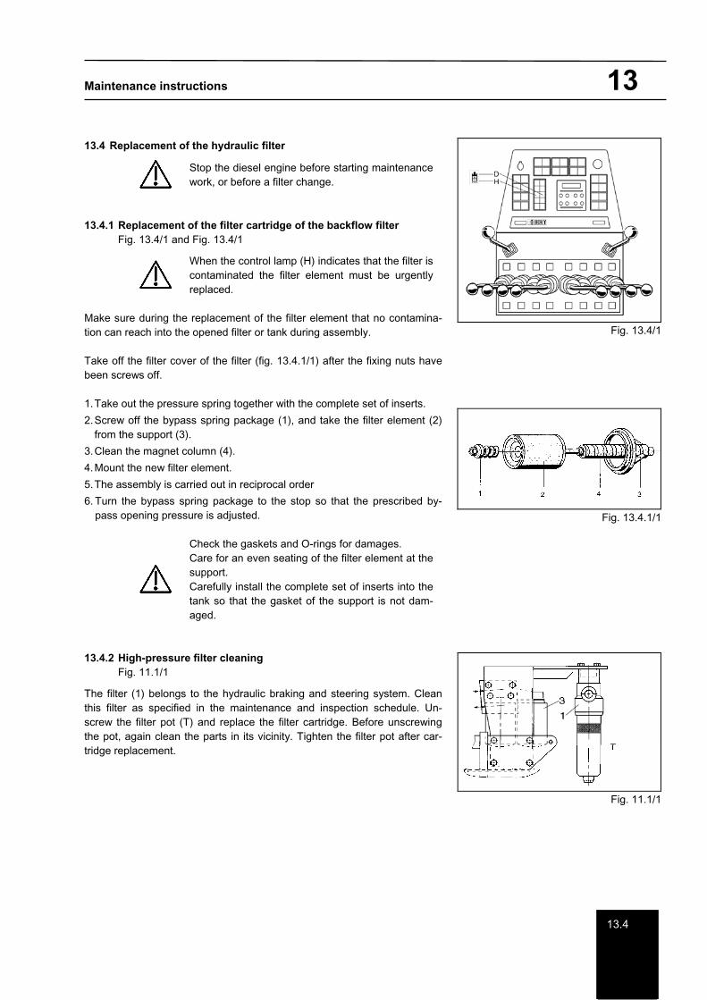
13.4 Replacement of the hydraulic filter
Stop the diesel engine before starting maintenance work, or before a filter change.
13.4.1 Replacement of the filter cartridge of the backflow filter Fig. 13.4/1 and Fig. 13.4/1
When the control lamp (H) indicates that the filter is contaminated the filter element must be urgently replaced.
Make sure during the replacement of the filter element that no contamina-tion can reach into the opened filter or tank during assembly.
Take off the filter cover of the filter (fig. 13.4.1/1) after the fixing nuts have been screws off.
1. Take out the pressure spring together with the complete set of inserts.
2. Screw off the bypass spring package (1), and take the filter element (2) from the support (3).
3. Clean the magnet column (4).
4. Mount the new filter element.
5. The assembly is carried out in reciprocal order
6. Turn the bypass spring package to the stop so that the prescribed by-pass opening pressure is adjusted.
Check the gaskets and O-rings for damages. Care for an even seating of the filter element at the support. Carefully install the complete set of inserts into the tank so that the gasket of the support is not dam-aged.
13.4.2 High-pressure filter cleaning Fig. 11.1/1
The filter (1) belongs to the hydraulic braking and steering system. Clean this filter as specified in the maintenance and inspection schedule. Un-screw the filter pot (T) and replace the filter cartridge. Before unscrewing the pot, again clean the parts in its vicinity. Tighten the filter pot after car-tridge replacement.
Fig. 13.4/1
Fig. 13.4.1/1
Fig. 11.1/1
Maintenance instructions 13
13.4
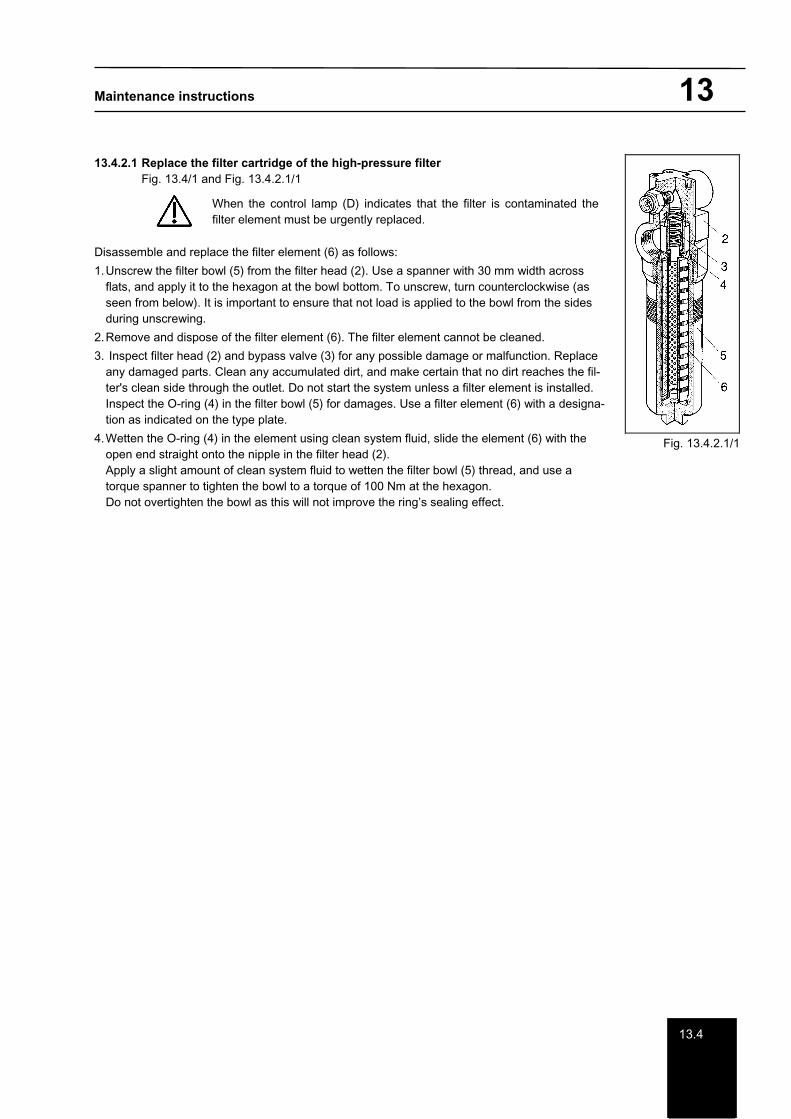
13.4.2.1 Replace the filter cartridge of the high-pressure filter Fig. 13.4/1 and Fig. 13.4.2.1/1
When the control lamp (D) indicates that the filter is contaminated the filter element must be urgently replaced.
Disassemble and replace the filter element (6) as follows:
1. Unscrew the filter bowl (5) from the filter head (2). Use a spanner with 30 mm width across flats, and apply it to the hexagon at the bowl bottom. To unscrew, turn counterclockwise (as seen from below). It is important to ensure that not load is applied to the bowl from the sides during unscrewing.
2. Remove and dispose of the filter element (6). The filter element cannot be cleaned.
3. Inspect filter head (2) and bypass valve (3) for any possible damage or malfunction. Replace any damaged parts. Clean any accumulated dirt, and make certain that no dirt reaches the fil-ter's clean side through the outlet. Do not start the system unless a filter element is installed. Inspect the O-ring (4) in the filter bowl (5) for damages. Use a filter element (6) with a designa-tion as indicated on the type plate.
4. Wetten the O-ring (4) in the element using clean system fluid, slide the element (6) with the open end straight onto the nipple in the filter head (2). Apply a slight amount of clean system fluid to wetten the filter bowl (5) thread, and use a torque spanner to tighten the bowl to a torque of 100 Nm at the hexagon. Do not overtighten the bowl as this will not improve the ring’s sealing effect.
Fig. 13.4.2.1/1
Maintenance instructions 14
14
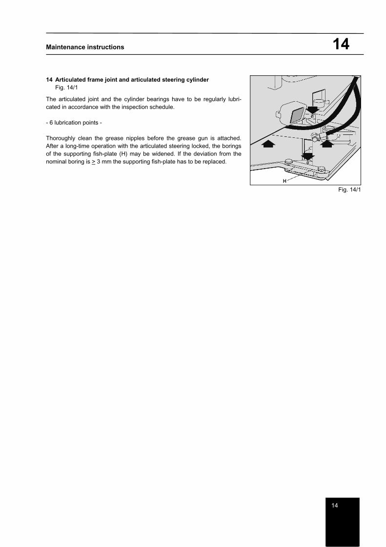
14 Articulated frame joint and articulated steering cylinder Fig. 14/1
The articulated joint and the cylinder bearings have to be regularly lubri-cated in accordance with the inspection schedule.
- 6 lubrication points -
Thoroughly clean the grease nipples before the grease gun is attached. After a long-time operation with the articulated steering locked, the borings of the supporting fish-plate (H) may be widened. If the deviation from the nominal boring is > 3 mm the supporting fish-plate has to be replaced.
Fig. 14/1

Maintenance instructions 15/16
1516
15 Lubrication of the front blade Fig. 15/1 and Fig. 15/2
- 11 lubrication points -
3 lubrication points - Cylinder bearing (Fig. 15/1)
8 lubrication points - front blade (Fig 15/2) There are recessed lubricating points in the bearing bolt.
Fig. 15/1
Fig. 15/2
16 Rear Ripper Fig. 16/1
- 2 lubrication points -
Heads of the piston rods of the right and left cylinders.
Fig. 16/1
Maintenance instructions 17
17
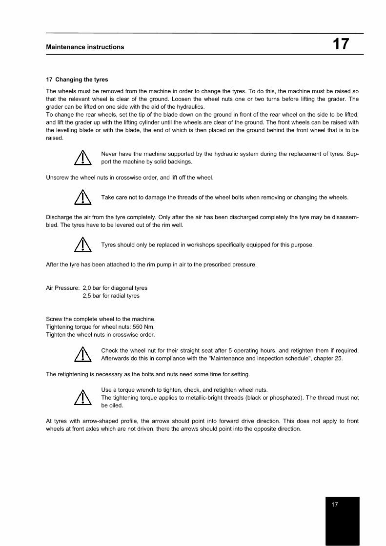
17 Changing the tyres
The wheels must be removed from the machine in order to change the tyres. To do this, the machine must be raised so that the relevant wheel is clear of the ground. Loosen the wheel nuts one or two turns before lifting the grader. The grader can be lifted on one side with the aid of the hydraulics. To change the rear wheels, set the tip of the blade down on the ground in front of the rear wheel on the side to be lifted, and lift the grader up with the lifting cylinder until the wheels are clear of the ground. The front wheels can be raised with the levelling blade or with the blade, the end of which is then placed on the ground behind the front wheel that is to be raised.
Never have the machine supported by the hydraulic system during the replacement of tyres. Sup-port the machine by solid backings.
Unscrew the wheel nuts in crosswise order, and lift off the wheel.
Take care not to damage the threads of the wheel bolts when removing or changing the wheels.
Discharge the air from the tyre completely. Only after the air has been discharged completely the tyre may be disassem-bled. The tyres have to be levered out of the rim well.
Tyres should only be replaced in workshops specifically equipped for this purpose.
After the tyre has been attached to the rim pump in air to the prescribed pressure.
Air Pressure: 2,0 bar for diagonal tyres 2,5 bar for radial tyres
Screw the complete wheel to the machine. Tightening torque for wheel nuts: 550 Nm. Tighten the wheel nuts in crosswise order.
Check the wheel nut for their straight seat after 5 operating hours, and retighten them if required. Afterwards do this in compliance with the "Maintenance and inspection schedule", chapter 25.
The retightening is necessary as the bolts and nuts need some time for setting.
Use a torque wrench to tighten, check, and retighten wheel nuts. The tightening torque applies to metallic-bright threads (black or phosphated). The thread must not be oiled.
At tyres with arrow-shaped profile, the arrows should point into forward drive direction. This does not apply to front wheels at front axles which are not driven, there the arrows should point into the opposite direction.

Maintenance instructions 17
17.1
17.1 Tyre Ballast (Option)
As extra ballast to increase the available tractive force, the interior volume of the tyre can be half-filled with an anti-freeze solution with a density of 1.19 kg/dm3 (-30°C). To do this, use the tyre inflating equipment supplied in the on-board ac-cessory set. To check the 50 % level, the wheel must first be turned so that the valve is at either the 3 o'clock or 9 o'clock position. Pumping up the air pressure in the tyre may only be done with the valve in the 12 o'clock position.
Recommendation: Topping up or disposing of the anti-freeze solution should be done by a tyre company.
17.1.1 How to use the combined „WASSER-BOY“ water filler and drainage unit
Filling water into the pinionsI.
Jack up the pinion; Unscrew the valve insert (1) from tube valve 47 GW. Depressurise, and screw on the WASSER-BOY (2).
II.Set the pinion to position II, and connect the water hose (3);
Fill in water (4); Air will escape through the small tube (5) and through the opening (6). (The tyre is filled sufficiently when water is flowing out of opening (6).
III.Put tube valve 47 GW to a vertical position.
Unscrew the WASSER-BOY (2), and screw on the valve insert (1).
IV.Fill compressed air into the tyre as per specification (7).
Dry the WASSER-BOY, and pack it in the protective sheathing.
V.Pinion drainage
Jack up the pinion; Unscrew the valve insert (1) from tube valve 47 GW.
Let the water flow out; screw on the WASSER-BOY (2).
VI.Screw valve insert (1) into the WASSER-BOY (2).
VII.Slide on the compressed-air hose (7);
Fill in compressed air; The water rises into the small tube (5), and escapes through the opening (6).
VIII.Unscrew the WASSER-BOY (2), and screw on the valve insert (1).
Fill compressed air into the tyre as per specification. Dry the Wasser-Boy, and pack it in the protective sheathing.
Maintenance instructions 18
1818.1
18 Electrical system
18.1 Electrical system on the machine
Before you start any work at the electrical system of the machine, put the system out of operation. For this purpose, disconnect the negative and afterwards the positive cables from the battery. When you reattach the cables, start with the positive cable and then fix the negative cable.
Do not start the engine if the batteries are not properly connected to the machine’s system. Never disconnect the batteries, and never turn off the master switch when the engine is running.
The non-compliance with the above rules will lead to destruction of electrical and electronic components. During each maintenance work, urgently check the cables for loose or contaminated contacts, for damages of the insula-tion or cable breaks. Before the beginning of possible required welding activities at the machine urgently disconnect the dynamo. Do not mix up the polarity of the auxiliary batteries in case of an external start.
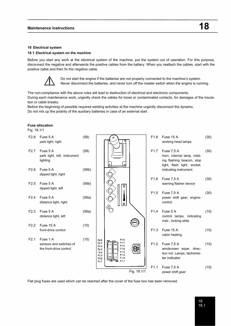
Fuse allocation Fig. 18.1/1
Flat plug fuses are used which can be reached after the cover of the fuse box has been removed.
F2.8
F2.7
F2.6
F2.5
F2.4
F2.3
F2.2
F2.1
Fuse 5 A park light, right
Fuse 5 A park light, left, instrument lighting
Fuse 5 A dipped light, right
Fuse 5 A dipped light, left
Fuse 5 A distance light, right
Fuse 5 A distance light, left
Fuse 15 A front-drive control
Fuse 1 A sensors and switches of the front-drive control
(58)
(58)
(56b)
(56b)
(56a)
(56a)
(15)
(15)
Fig. 18.1/1
F1.8
F1.7
F1.6
F1.5
F1.4
F1.3
F1.2
F1.1
Fuse 15 A working head lamps
Fuse 7,5 A horn, internal lamp, rotat-ing flashing beacon, stop light, flash light, socket, indicating instrument
Fuse 7,5 A warning flasher device
Fuse 7,5 A power shift gear, engine-control
Fuse 5 A control lamps, indicating instr., locking slide
Fuse 15 A cabin heating
Fuse 7,5 A windscreen wiper, direc-tion ind. Lamps, tachome-ter indicator
Fuse 7,5 A power shift gear
(30)
(30)
(30)
(30)
(15)
(15)
(15)
(15)

Maintenance instructions 18
18.2
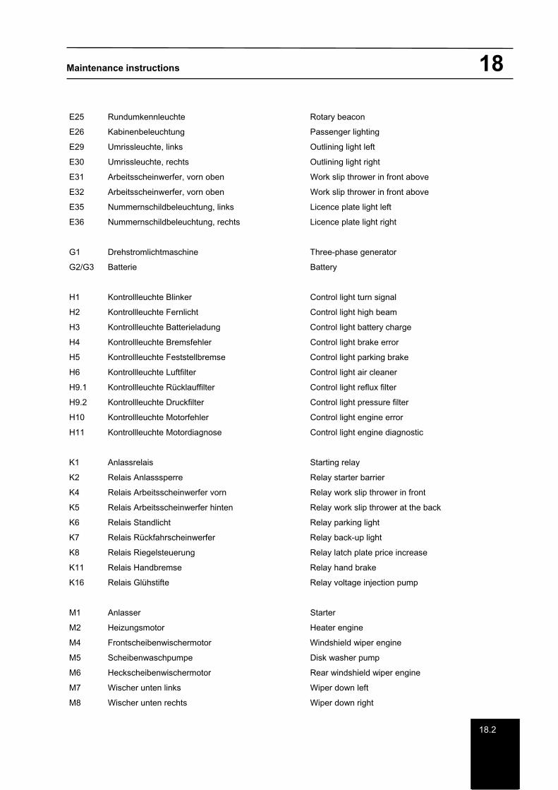
18.2 Electrical symbols
A4 Getriebe 6 WG 115 Transmission 6 WG 115
A5 Stecker Motorsteuerung Plug motor control
A6 Fußgas Foot gas
A7 Handgas Hand gas
B1.1 Horn Horn
B2 Druckschalter Bremsfehler Pressure button brake error
B3 Druckschalter Feststellbremse Pressure button parking brake
B4 Druckschalter Stopplicht Pressure button stop light
B5 Temperatur - Geber Getriebeöl Temperature transmitter transmission oil
B6 Druckschalter Luftfilter Pressure button air cleaner
B8.1 Druckschalter Rücklauffilter Pressure button reflux filter
B8.2 Druckschalter Druckfilter Pressure button pressure filter
B12 Temperatur - Geber Kühlmittel Temperature transmitter coolant
B14 Dieseltankgeber Diesel tank giver
E1 Arbeitsscheinwerfer, vorn links Work slip thrower in front left
E2 Arbeitsscheinwerfer, vorn rechts Work slip thrower in front right
E3.1 Arbeitsscheinwerfer, hinten links Work slip thrower at the rear left
E3.2 Arbeitsscheinwerfer, hinten rechts Work slip thrower at the rear right
E4 Rückfahrscheinwerfer Back-up light
E5 Fernlicht links High beam left
E6 Abblendlicht links Headlight low beam left
E7 Standlicht links Parking light left
E8 Fernlicht rechts High beam right
E9 Abblendlicht rechts Headlight low beam right
E10 Standlicht rechts Parking light right
E11 Blinklicht, vorn links Signal light in front left
E12 Blinklicht, vorn rechts Signal light in front right
E13 Blinklicht, Mitte links Signal light center left
E14 Blinklicht, Mitte rechts Signal light at the rear right
E15 Begrenzungslicht, vorn links Boundary light in front left
E16 Begrenzungslicht, vorn rechts Boundary light in front right
E17 Schlusslicht, hinten links Tail light at the rear left
E18 Stopplicht, hinten links Stop light at the rear left
E19 Blinklicht, hinten links Signal light at the rear left
E20 Schlusslicht, hinten rechts Tail light at the rear right
E21 Stopplicht, hinten rechts Stop light at the rear right
E22 Blinklicht, hinten rechts Signal light at the rear right
Maintenance instructions 18
18.2
E25 Rundumkennleuchte Rotary beacon
E26 Kabinenbeleuchtung Passenger lighting
E29 Umrissleuchte, links Outlining light left
E30 Umrissleuchte, rechts Outlining light right
E31 Arbeitsscheinwerfer, vorn oben Work slip thrower in front above
E32 Arbeitsscheinwerfer, vorn oben Work slip thrower in front above
E35 Nummernschildbeleuchtung, links Licence plate light left
E36 Nummernschildbeleuchtung, rechts Licence plate light right
G1 Drehstromlichtmaschine Three-phase generator
G2/G3 Batterie Battery
H1 Kontrollleuchte Blinker Control light turn signal
H2 Kontrollleuchte Fernlicht Control light high beam
H3 Kontrollleuchte Batterieladung Control light battery charge
H4 Kontrollleuchte Bremsfehler Control light brake error
H5 Kontrollleuchte Feststellbremse Control light parking brake
H6 Kontrollleuchte Luftfilter Control light air cleaner
H9.1 Kontrollleuchte Rücklauffilter Control light reflux filter
H9.2 Kontrollleuchte Druckfilter Control light pressure filter
H10 Kontrollleuchte Motorfehler Control light engine error
H11 Kontrollleuchte Motordiagnose Control light engine diagnostic
K1 Anlassrelais Starting relay
K2 Relais Anlasssperre Relay starter barrier
K4 Relais Arbeitsscheinwerfer vorn Relay work slip thrower in front
K5 Relais Arbeitsscheinwerfer hinten Relay work slip thrower at the back
K6 Relais Standlicht Relay parking light
K7 Relais Rückfahrscheinwerfer Relay back-up light
K8 Relais Riegelsteuerung Relay latch plate price increase
K11 Relais Handbremse Relay hand brake
K16 Relais Glühstifte Relay voltage injection pump
M1 Anlasser Starter
M2 Heizungsmotor Heater engine
M4 Frontscheibenwischermotor Windshield wiper engine
M5 Scheibenwaschpumpe Disk washer pump
M6 Heckscheibenwischermotor Rear windshield wiper engine
M7 Wischer unten links Wiper down left
M8 Wischer unten rechts Wiper down right

Maintenance instructions 18
18.2
P5 Multifunktionsanzeige MFA 10 Multifunction announcement
P6 Fahrtenschreiber Travel writer
R2 Glühstifte Preliminary heating
S1 Zündschloss Starter lock
S2 Lichtdrehschalter Light spindle switch
S3 Schalter Scheibenwischer Switch windshield wiper
S4 Impulsgeber Pulse generator
S5 Schalter Scheibenwischer, hinten Switch windshield wiper at the back
S6 Warnblinkschalter Warning light switch
S7 Blinkgeber Flasher
S8 Kombischalter Lenksäule Combination switch steering column
S10 Schalter Rundumkennleuchte Switch rotary beacon
S11 Schalter Leuchtentest Switch light test
S12.1 Schalter Arbeitsscheinwerfer, vorn Switch work slip thrower in front
S12.2 Schalter Arbeitsscheinwerfer, hinten Switch work slip thrower at the back
S15 Schalter Waschanlage Switch washing plant
S18 Schalter Riegel Drehbrücke Switch latch plate swing bridge
S32 Schalter Arbeitsscheinwerfer, oben Switch work slip thrower above
S33 Hauptschalter Main switch
S35 Schalter Wischer, unten links Switch wiper down left
S36 Schalter Wischer, unten rechts Switch wiper down right
S40 Schalter Feststellbremse Switch parking brake
V1 Diodenblock Leuchtentest Diode block light test
X Steckverbinder Plug connector
Y4 Magnetventil Festellbremse Single solenoid valve parking brake
Y6 Magnetventil Riegel Single solenoid valve latch plate
Maintenance instructions 19
19
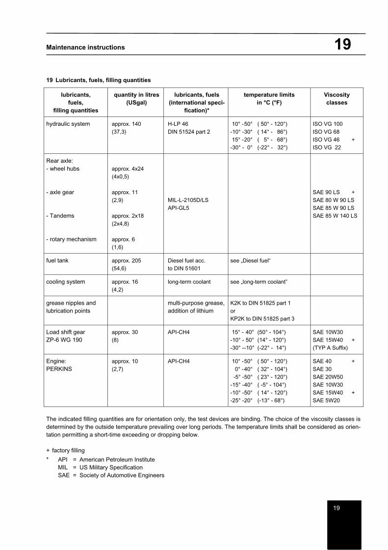
19 Lubricants, fuels, filling quantities
lubricants,fuels,
filling quantities
quantity in litres (USgal)
lubricants, fuels (international speci-
fication)*
temperature limits in °C (°F)
Viscosity classes
hydraulic system approx. 140 (37,3)
H-LP 46 DIN 51524 part 2
10° - 50° ( 50° - 120°) -10° - 30° ( 14° - 86°) 15° - 20° ( 5° - 68°) -30° - 0° (-22° - 32°)
ISO VG 100 ISO VG 68 ISO VG 46 + ISO VG 22
Rear axle: - wheel hubs
- axle gear
- Tandems
- rotary mechanism
approx. 4x24 (4x0,5)
approx. 11 (2,9)
approx. 2x18 (2x4,8)
approx. 6 (1,6)
MIL-L-2105D/LS API-GL5
SAE 90 LS + SAE 80 W 90 LS SAE 85 W 90 LS SAE 85 W 140 LS
fuel tank approx. 205 (54,6)
Diesel fuel acc. to DIN 51601
see „Diesel fuel“
cooling system approx. 16 (4,2)
long-term coolant see „long-term coolant”
grease nipples and lubrication points
multi-purpose grease, addition of lithium
K2K to DIN 51825 part 1 orKP2K to DIN 51825 part 3
Load shift gear ZP-6 WG 190
approx. 30 (8)
API-CH4 15° - 40° (50° - 104°) -10° - 50° (14° - 120°) -30° - -10° (-22° - 14°)
SAE 10W30 SAE 15W40 + (TYP A Suffix)
Engine: PERKINS
approx. 10 (2,7)
API-CH4 10° - 50° ( 50° - 120°) 0° - 40° ( 32° - 104°) -5° - 50° ( 23° - 120°) -15° - 40° ( -5° - 104°) -10° - 50° ( 14° - 120°) -25° - 20° (-13° - 68°)
SAE 40 + SAE 30 SAE 20W50 SAE 10W30 SAE 15W40 + SAE 5W20
The indicated filling quantities are for orientation only, the test devices are binding. The choice of the viscosity classes isdetermined by the outside temperature prevailing over long periods. The temperature limits shall be considered as orien-tation permitting a short-time exceeding or dropping below.
+ factory filling
* API = American Petroleum Institute MIL = US Military Specification SAE = Society of Automotive Engineers
Maintenance instructions 20
20
20 Lubricants
Only use lubricants which fulfil the specifications mentioned below and which are internationally known.
Do not mix engine, gear and hydraulic oils!
The viscosity limits (viscosity classes) mentioned in the table “”Lubricants, fuels and quantities”, e.g. ISO VG 46I corre-spond to the codes DIN 51 519 and ISO 3448.
Engine oils (specifications) API-CH4
Hydraulic systems (specifications) The hydraulic high-duty drive requires the use of oil according to the a.m. specifications for the hydraulic system.
Gear oils for wet brakes (specifications) MIL-L-2105 D/LS API-GL5 LS
Gear oils (specifications) MIL-L-2105 A API-GL5
Lubricating grease lithium-saponified, drop point > 170°C walk penetration 275/295 under the addition of molybdenum (IV)-sulphide NLGI class 2 (DIN 518 18)
Viscosity classes
The viscosity classes can be seen from the table ”Lubricants, fuels and quantities”. Their choice is determined by the outside temperature prevailing over long periods. The temperature limits shall be considered as orientation permitting a short-time exceeding or dropping below.
Maintenance instructions 21
21
21 Diesel fuels
The engine will generate the specified power and show the required running properties only if high-quality fuel is used. The fuel recommended to be used with Perkins engines shall have the following characteristics:
Cetane number min. 45
Viscosity 2.5/4.5 cSt at 40°C (104°F)
Density 0.835 to 0.855 kg/l
Sulphur content max. 0.5 %
Boiling point curve 85 % at 350 °C
Cetane number This number determines the ignition performance. A low-cetane fuel may cause starting problems and affect combustion.
Viscosity Viscosity is the flowability of the fuel and can affect - if outside the specified range - the running properties of the engine.
Density A low density will reduce the engine power, a high density increases the engine power and exhaust gas turbidity.
Sulphur A high sulphur content (normally not found in Europe, North America and Australasia) may result in increased engine wear. Where only fuel with a high sulphur content is available, either a high-grade oil must be used or the oil must be changed frequently.
Boiling point curve Refers to the mixture of different hydrocarbons in the fuel. A high ratio can have an influence on the combustion charac-teristics.
The frost resistance of diesel fuels is an important prerequisite for trouble-free operation in winter. When the tempera-tures drop to a point where paraffin precipitates in the diesel fuel, the filterability and flowability are hampered; the fuel filter and fuel lines are clogged.
The European mineral oil industry offers a diesel fuel for summer operation and one for winter operation (both in compli-ance with DIN 51 601).
Operation from - to Frost resistant to
Summer diesel fuel mid-March to mid-October to 0°C (32°F)
Winter diesel fuel mid-October to mid-March to 20°C (-4°F)
ESSO POLAR FUEL in cold areas in winter Below -20°C (-4°F)
In general, winter diesel fuels are frost resistant to a temperature of -20°C (-4 °F). If frost occurs in transient periods or the winter temperatures are below -20 °C (-4 °F), special diesel fuels with an improved frost resistance have to be used (see table above).
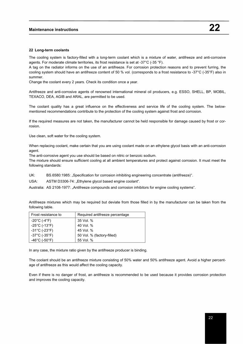
Maintenance instructions 22
22
22 Long-term coolants
The cooling system is factory-filled with a long-term coolant which is a mixture of water, antifreeze and anti-corrosive agents. For moderate climate territories, its frost resistance is set at -37°C (-35 °F). A tag on the radiator informs on the use of an antifreeze. For corrosion protection reasons and to prevent furring, the cooling system should have an antifreeze content of 50 % vol. (corresponds to a frost resistance to -37°C (-35°F) also in summer.Change the coolant every 2 years. Check its condition once a year.
Antifreeze and anti-corrosive agents of renowned international mineral oil producers, e.g. ESSO, SHELL, BP, MOBIL, TEXACO, DEA, AGIB and ARAL, are permitted to be used.
The coolant quality has a great influence on the effectiveness and service life of the cooling system. The below-mentioned recommendations contribute to the protection of the cooling system against frost and corrosion.
If the required measures are not taken, the manufacturer cannot be held responsible for damage caused by frost or cor-rosion.
Use clean, soft water for the cooling system.
When replacing coolant, make certain that you are using coolant made on an ethylene glycol basis with an anti-corrosion agent. The anti-corrosive agent you use should be based on nitric or benzoic sodium. The mixture should ensure sufficient cooling at all ambient temperatures and protect against corrosion. It must meet the following standards:
UK: BS.6580:1985: „Specification for corrosion inhibiting engineering concentrate (antifreeze)“.
USA: ASTM D3306-74: „Ethylene glycol based engine coolant“.
Australia: AS 2108-1977: „Antifreeze compounds and corrosion inhibitors for engine cooling systems“.
Antifreeze mixtures which may be required but deviate from those filled in by the manufacturer can be taken from the following table.
Frost resistance to Required antifreeze percentage
-20°C (-4°F) -25°C (-13°F) -31°C (-23°F) -37°C (-35°F) -46°C (-50°F)
35 Vol. % 40 Vol. % 45 Vol. % 50 Vol. % (factory-filled) 55 Vol. %
In any case, the mixture ratio given by the antifreeze producer is binding.
The coolant should be an antifreeze mixture consisting of 50% water and 50% antifreeze agent. Avoid a higher percent-age of antifreeze as this would affect the cooling capacity.
Even if there is no danger of frost, an antifreeze is recommended to be used because it provides corrosion protection and improves the cooling capacity.

Maintenance instructions 22
22
In tropical regions where the air temperature lies above +35 °C (95 °F), the low thermal conductivity of the long-term coolant may lead to an overheating of the engine. In this case, use water instead of the long-term coolant, and add a corrosion inhibitor to the water to prevent corrosion and furring. Use the mixture ratio specified by the maker.
Change the water/corrosion inhibitor mixture every 6 months; in case of doubt, ask the supplier.
Add the antifreeze and/or corrosion inhibitor to a bucket-full of water (tap water) and mix. It is not sufficient just to pour the water and antifreeze successively into the radiator as thorough mixing in the cooling system would take too much time.
The cooling system features only little evaporation losses. The losses can be compensated by adding clean water with a low lime content.
Do not fill in too much coolant because it might overflow when it heats up. Moreover, if water is added too often, the concentrate would be impermissibly diluted (see Section „Changing the coolant“ in these instructions).
In emergency cases, also normal clean water may serve as coolant. However, it should be replaced as soon as possible with the required long-term coolant.
Check the latter for frost resistance before the cold season.
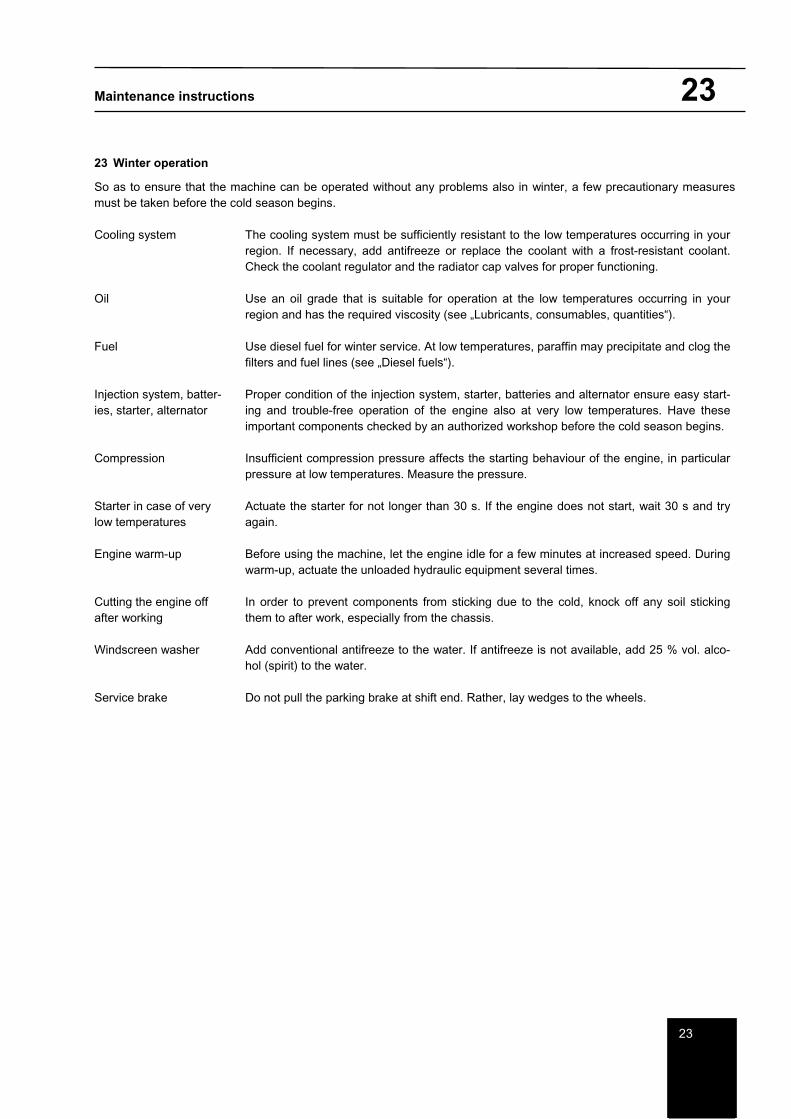
Maintenance instructions 23
23
23 Winter operation
So as to ensure that the machine can be operated without any problems also in winter, a few precautionary measures must be taken before the cold season begins.
Cooling system The cooling system must be sufficiently resistant to the low temperatures occurring in your region. If necessary, add antifreeze or replace the coolant with a frost-resistant coolant. Check the coolant regulator and the radiator cap valves for proper functioning.
Oil Use an oil grade that is suitable for operation at the low temperatures occurring in your region and has the required viscosity (see „Lubricants, consumables, quantities“).
Fuel Use diesel fuel for winter service. At low temperatures, paraffin may precipitate and clog the filters and fuel lines (see „Diesel fuels“).
Injection system, batter-ies, starter, alternator
Proper condition of the injection system, starter, batteries and alternator ensure easy start-ing and trouble-free operation of the engine also at very low temperatures. Have these important components checked by an authorized workshop before the cold season begins.
Compression Insufficient compression pressure affects the starting behaviour of the engine, in particular pressure at low temperatures. Measure the pressure.
Starter in case of very low temperatures
Actuate the starter for not longer than 30 s. If the engine does not start, wait 30 s and try again.
Engine warm-up Before using the machine, let the engine idle for a few minutes at increased speed. During warm-up, actuate the unloaded hydraulic equipment several times.
Cutting the engine off after working
In order to prevent components from sticking due to the cold, knock off any soil sticking them to after work, especially from the chassis.
Windscreen washer Add conventional antifreeze to the water. If antifreeze is not available, add 25 % vol. alco-hol (spirit) to the water.
Service brake Do not pull the parking brake at shift end. Rather, lay wedges to the wheels.
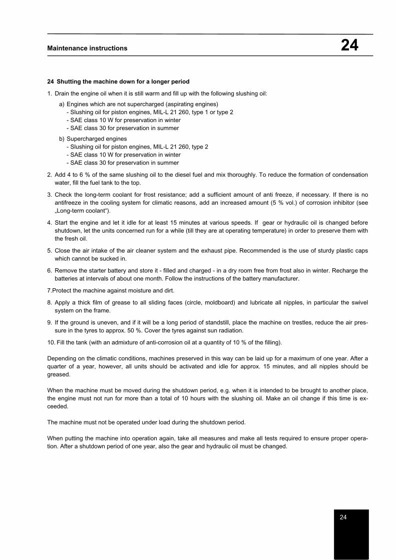
Maintenance instructions 24
24
24 Shutting the machine down for a longer period
1. Drain the engine oil when it is still warm and fill up with the following slushing oil:
a) Engines which are not supercharged (aspirating engines) - Slushing oil for piston engines, MIL-L 21 260, type 1 or type 2 - SAE class 10 W for preservation in winter - SAE class 30 for preservation in summer
b) Supercharged engines - Slushing oil for piston engines, MIL-L 21 260, type 2 - SAE class 10 W for preservation in winter - SAE class 30 for preservation in summer
2. Add 4 to 6 % of the same slushing oil to the diesel fuel and mix thoroughly. To reduce the formation of condensation water, fill the fuel tank to the top.
3. Check the long-term coolant for frost resistance; add a sufficient amount of anti freeze, if necessary. If there is no antifreeze in the cooling system for climatic reasons, add an increased amount (5 % vol.) of corrosion inhibitor (see „Long-term coolant“).
4. Start the engine and let it idle for at least 15 minutes at various speeds. If gear or hydraulic oil is changed before shutdown, let the units concerned run for a while (till they are at operating temperature) in order to preserve them with the fresh oil.
5. Close the air intake of the air cleaner system and the exhaust pipe. Recommended is the use of sturdy plastic caps which cannot be sucked in.
6. Remove the starter battery and store it - filled and charged - in a dry room free from frost also in winter. Recharge the batteries at intervals of about one month. Follow the instructions of the battery manufacturer.
7.Protect the machine against moisture and dirt.
8. Apply a thick film of grease to all sliding faces (circle, moldboard) and lubricate all nipples, in particular the swivel system on the frame.
9. If the ground is uneven, and if it will be a long period of standstill, place the machine on trestles, reduce the air pres-sure in the tyres to approx. 50 %. Cover the tyres against sun radiation.
10. Fill the tank (with an admixture of anti-corrosion oil at a quantity of 10 % of the filling).
Depending on the climatic conditions, machines preserved in this way can be laid up for a maximum of one year. After a quarter of a year, however, all units should be activated and idle for approx. 15 minutes, and all nipples should be greased.
When the machine must be moved during the shutdown period, e.g. when it is intended to be brought to another place, the engine must not run for more than a total of 10 hours with the slushing oil. Make an oil change if this time is ex-ceeded.
The machine must not be operated under load during the shutdown period.
When putting the machine into operation again, take all measures and make all tests required to ensure proper opera-tion. After a shutdown period of one year, also the gear and hydraulic oil must be changed.
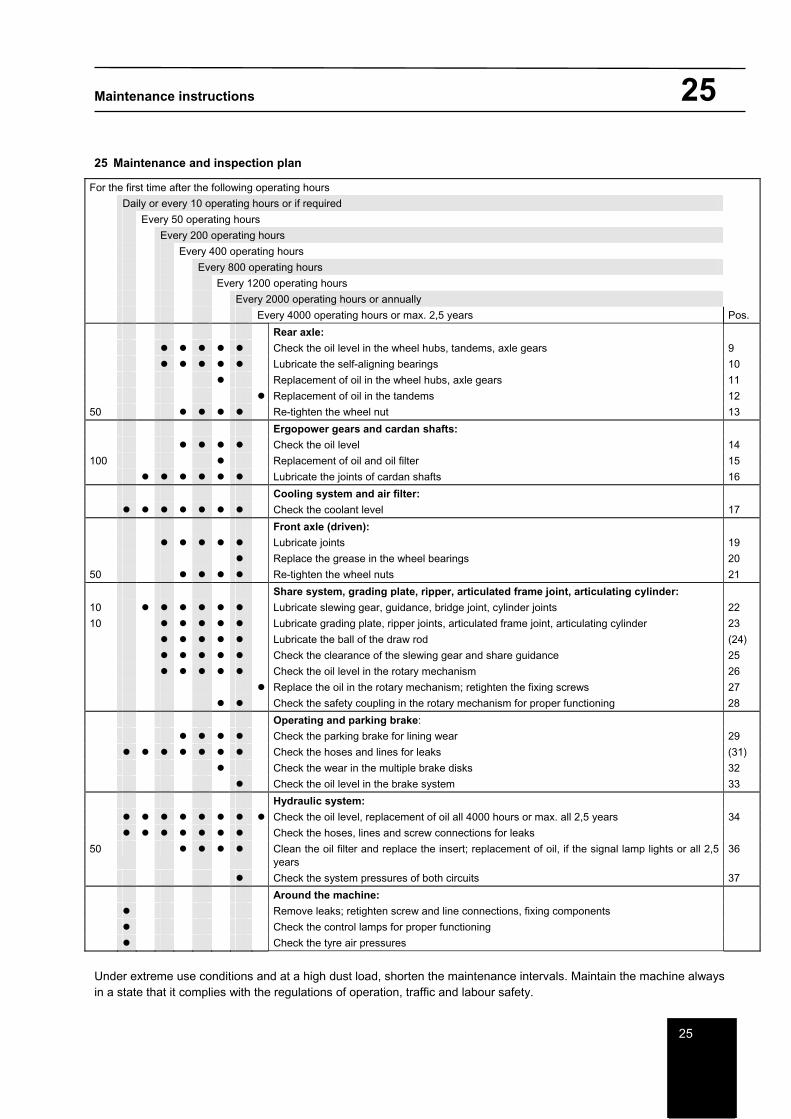
Maintenance instructions 25
25
25 Maintenance and inspection plan
For the first time after the following operating hours
Daily or every 10 operating hours or if required
Every 50 operating hours
Every 200 operating hours
Every 400 operating hours
Every 800 operating hours
Every 1200 operating hours
Every 2000 operating hours or annually
Every 4000 operating hours or max. 2,5 years Pos.
Rear axle:
Check the oil level in the wheel hubs, tandems, axle gears 9
Lubricate the self-aligning bearings 10
Replacement of oil in the wheel hubs, axle gears 11
Replacement of oil in the tandems 12
50 Re-tighten the wheel nut 13
Ergopower gears and cardan shafts:
Check the oil level 14
100 Replacement of oil and oil filter 15
Lubricate the joints of cardan shafts 16
Cooling system and air filter:
Check the coolant level 17
Front axle (driven):
Lubricate joints 19
Replace the grease in the wheel bearings 20
50 Re-tighten the wheel nuts 21
Share system, grading plate, ripper, articulated frame joint, articulating cylinder:
10 Lubricate slewing gear, guidance, bridge joint, cylinder joints 22
10 Lubricate grading plate, ripper joints, articulated frame joint, articulating cylinder 23
Lubricate the ball of the draw rod (24)
Check the clearance of the slewing gear and share guidance 25
Check the oil level in the rotary mechanism 26
Replace the oil in the rotary mechanism; retighten the fixing screws 27
Check the safety coupling in the rotary mechanism for proper functioning 28
Operating and parking brake:
Check the parking brake for lining wear 29
Check the hoses and lines for leaks (31)
Check the wear in the multiple brake disks 32
Check the oil level in the brake system 33
Hydraulic system:
Check the oil level, replacement of oil all 4000 hours or max. all 2,5 years 34
Check the hoses, lines and screw connections for leaks
50 Clean the oil filter and replace the insert; replacement of oil, if the signal lamp lights or all 2,5 years
36
Check the system pressures of both circuits 37
Around the machine:
Remove leaks; retighten screw and line connections, fixing components
Check the control lamps for proper functioning
Check the tyre air pressures
Under extreme use conditions and at a high dust load, shorten the maintenance intervals. Maintain the machine always in a state that it complies with the regulations of operation, traffic and labour safety.

Maintenance instructions 25
25