Embed Size (px)
Citation preview
WASTEWATER GRAVITY
SYSTEM
STANDARDS & SPECIFICATIONS MANUAL
MOORE COUNTY PUBLIC WORKS DEPARTMENT
AMENDED: June 2017
October 2017

PREFACE
This Manual is for the Moore County Public Utilities and the East Moore Water District water
and sewer systems, all of which are under the Moore County Public Works Department
(MCPW).
These standards are for design and construction of wastewater distribution facilities which will
come under the jurisdiction of MCPW. These standards alone do not constitute a complete
set of construction documents. The owner’s or developer’s Professional Engineer is
responsible for design and computation of complete construction and contract documents. These standards are set forth as the minimal requirements to achieve a suitable quality level for
utilities which will become the property of MCPW.
The standards do not include a complete commentary on methods of installation and detailed
information of quality of workmanship in place. The owner’s or developer’s Professional
Engineer must include detailed information on methods of construction and should expand on
the testing and any of the special requirements to the engineer’s satisfaction, subject to the
approval of MCPW.
From time to time, these standards will be amended and/or expanded at the request of the
MCPW Engineering Department and with approval of the Director. It will be the responsibility
of the owner or developer to contact the MCPW to obtain updated standards.
There may be circumstances whereby the design engineer may wish to propose changes or
modifications to these standards, when this occurs permission from the County Engineer shall be
obtained prior to submission to the North Carolina Department of Environmental Quality
(NCDEQ).
Disclaimer
To the best of its ability, the County has ensured that the material presented in this manual is
accurate and reliable. However, the design of engineered facilities requires considerable
judgment on the part of the designer. It is the responsibility of the design professional to ensure
that techniques utilized are appropriate for a given situation. Therefore, neither the County of
Moore nor any officer, employee or agent of the County accepts any responsibility for improper
design, loss, damage, or injury as a result of the use of this manual.
TABLE OF CONTENTS
1.0 DESIGN 1
A. General
B. Hydraulic Design and Route Selection
C. Flow Determination
D. Sanitary Sewer Minimum Slope
E. Pipe Size
F. Maximum Velocity
G. Depth & Pipe Types
2.0 UTILITIES LOCATION 4
A. Easements
B. Water Supply Separation
C. Water Main Separation
D. Storm Sewer and Gas Main Separation
E. Building Separation
F. NCDOT Right-of-Way
G. Railroad Right-of-Way
H. Streets & Dead Ends
3.0 PIPE SIZING 5
4.0 PIPE INSTALLATION 6
A. General
B. Backfilling
C. Final Backfilling
5.0 DETAIL OF DESIGN 7
A. Minimum Size
B. Depth
C. Change in Pipe Size & Material
6.0 SERVICE LATERALS 8
7.0 SERVICE LATERALS MATERIALS 9
A. General Requirements
B. PVC Service Pipe & Fittings
C. Service Saddles on DIP
D. Service Saddles for PVC (up to12”)
E. Service Cleanout Protector Boxes
8.0 SEWER BACKWATER PREVENTION DEVICES 10
9.0 GREASE TRAPS 11
10.0 MANHOLES 11
A. General Features
B. Location
C. Diameter
D. Drop Type
E. Bench/Shelf
F. Water Tightness
G. Precast Manholes
H. Manhole Frame and Cover
I. Stone for Stabilization of Trench Foundation
J. Special Coating Requirements
K. Rings
11.0 STREAMS & OTHER WATER BODIES 15
A. Stream Crossing
B. Aerial Crossing
C. Anti-Seepage Collars
12.0 PIPE MATERIALS 18
A. Pipe Size & Types
B. Ductile Iron Sewer Pipe
C. PVC Gravity Sewer Pipe
D. Steel (Casing) Pipe
13.0 INSPECTION AND TESTING OF GRAVITY SEWERS 19
A. Visual Inspection of Pipeline Interior and Manholes
B. Low Pressure Air Tests
C. Infiltration Tests
D. Deflection Testing
E. Ex-Filtration Tests
F. Vacuum Testing – Manholes
G. Spark (Holiday) Test
14.0 CCTV INSPECTION OF GRAVITY SEWERS 21
A. Qualifications
B. Submittals
C. Equipment
D. Digital Video
E. Execution
F. Contractor Responsibility
G. Acceptance
H. Water Use
15.0 ABANDONMENT OF MAINS AND SERVICES 23
DETAIL DRAWINGS Attached
SS 1 Storm and Gas Crossing
SS 2 Pipe Installation PVC and DIP
SS 3 SDR to DIP Transition
SS 4 Manhole Inside Drop Service Connection
SS 5 Service Connection and Cleanout
SS 6 Sanitary Sewer Tap
SS 7 Sewer Cleanout, Frame & Cover
SS 8 Manhole Invert
SS 9 Vented Manhole
SS 10 Doghouse Manhole
SS 11 Shallow Manhole
SS 12 Manhole Warning Post
SS 13 Manhole Channel Slide
SS 14 Main Line Manhole Inside Drop
SS 15 Rubber Boot
SS 16 Lockable Manhole Frame and Cover
SS 17 4’ Standard Manhole
SS 18 Standard Manhole Frame and Cover
SS 29 Aerial Pipe Support H-Pile
SS 20 Aerial Pipe Support Reinforced Concrete
1 of 23
STANDARD & SPECIFICATIONS MANUAL - WASTEWATER GRAVITY SYSTEM
1.0 DESIGN
A. General
Moore County Public Works (MCPW) wastewater collection system design and
construction and non MCPW wastewater collection system design and construction,
which connect to the MCPW system, shall be in accordance with the standards and
requirements of Title 15A 2T Section .0100 -.1600 of the North Carolina Administrative
Code, Department of Environmental Quality, “Waste Not Discharged to Surface Waters”
(latest revision) and this Manual.
B. Hydraulic Design and Route Selection
The following procedures and criteria are to be used for sizing and hydraulic design of
gravity sanitary sewers. Generally, sewer outfalls and trunk mains shall be sized for the
future full development of the natural basin using the following criteria unless more
specific data is available. These design and peak flow calculations are not to be used to
calculate flows for wastewater permits. Wastewater extensions will be approved on the
basis of current actual land use and flow allocations as required by NCDEQ standards
and regulations.
1. Determine Drainage Basin and Population to be served
a. Outline the major basin on topographic maps. Identify and outline all sub-
basins and identify any other basins or sub-basins that will be pumping into
the sewer being designed.
b. Determine the acres to be served. Include the basins or sub-basins that will be
pumped into the sewer. If the area is undeveloped, reduce the area by 20% to
account for streets. Further reduce the area by any acreage that is not
considered developable (i.e. lakes, wetlands, greenways, recreation areas,
etc.). If the area is developed, reduce the area as necessary to allow for
existing streets.
c. For each basin and sub-basin, determine the existing population, land use and
zoning. Consideration shall be given to the maximum anticipated capacity of
commercial areas, of institutions, industrial parks, etc. Refer to the appropriate
area Land Use Plan to determine trends in land use and zoning and for
predictions of population growth rate.
2. Wastewater Flow Rates
The Engineer shall be responsible for insuring that the design discharge utilized in
sizing sewer collection facilities are adequate for the area, which the extension is
to serve and meets NCDEQ standards and regulations.
2 of 23
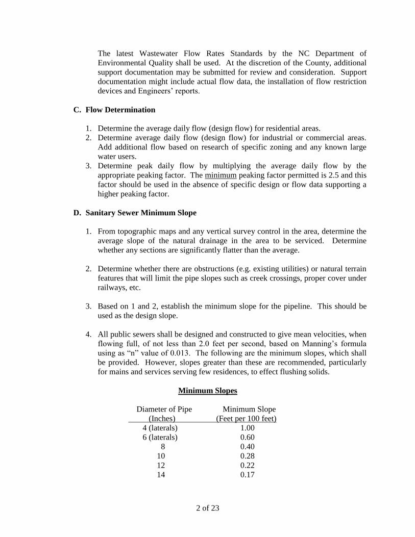
The latest Wastewater Flow Rates Standards by the NC Department of
Environmental Quality shall be used. At the discretion of the County, additional
support documentation may be submitted for review and consideration. Support
documentation might include actual flow data, the installation of flow restriction
devices and Engineers’ reports.
C. Flow Determination
1. Determine the average daily flow (design flow) for residential areas.
2. Determine average daily flow (design flow) for industrial or commercial areas.
Add additional flow based on research of specific zoning and any known large
water users.
3. Determine peak daily flow by multiplying the average daily flow by the
appropriate peaking factor. The minimum peaking factor permitted is 2.5 and this
factor should be used in the absence of specific design or flow data supporting a
higher peaking factor.
D. Sanitary Sewer Minimum Slope
1. From topographic maps and any vertical survey control in the area, determine the
average slope of the natural drainage in the area to be serviced. Determine
whether any sections are significantly flatter than the average.
2. Determine whether there are obstructions (e.g. existing utilities) or natural terrain
features that will limit the pipe slopes such as creek crossings, proper cover under
railways, etc.
3. Based on 1 and 2, establish the minimum slope for the pipeline. This should be
used as the design slope.
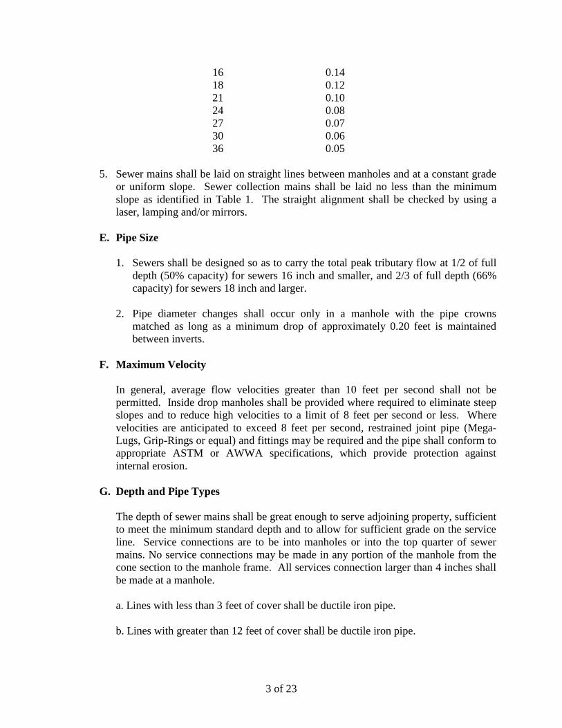
4. All public sewers shall be designed and constructed to give mean velocities, when
flowing full, of not less than 2.0 feet per second, based on Manning’s formula
using as “n” value of 0.013. The following are the minimum slopes, which shall
be provided. However, slopes greater than these are recommended, particularly
for mains and services serving few residences, to effect flushing solids.
Minimum Slopes
Diameter of Pipe Minimum Slope
(Inches) (Feet per 100 feet)
4 (laterals) 1.00
6 (laterals) 0.60
8 0.40
10 0.28
12 0.22
14 0.17
3 of 23
16 0.14
18 0.12
21 0.10
24 0.08
27 0.07
30 0.06
36 0.05
5. Sewer mains shall be laid on straight lines between manholes and at a constant grade
or uniform slope. Sewer collection mains shall be laid no less than the minimum
slope as identified in Table 1. The straight alignment shall be checked by using a
laser, lamping and/or mirrors.
E. Pipe Size
1. Sewers shall be designed so as to carry the total peak tributary flow at 1/2 of full
depth (50% capacity) for sewers 16 inch and smaller, and 2/3 of full depth (66%
capacity) for sewers 18 inch and larger.
2. Pipe diameter changes shall occur only in a manhole with the pipe crowns
matched as long as a minimum drop of approximately 0.20 feet is maintained
between inverts.
F. Maximum Velocity
In general, average flow velocities greater than 10 feet per second shall not be
permitted. Inside drop manholes shall be provided where required to eliminate steep
slopes and to reduce high velocities to a limit of 8 feet per second or less. Where
velocities are anticipated to exceed 8 feet per second, restrained joint pipe (Mega-
Lugs, Grip-Rings or equal) and fittings may be required and the pipe shall conform to
appropriate ASTM or AWWA specifications, which provide protection against
internal erosion.
G. Depth and Pipe Types
The depth of sewer mains shall be great enough to serve adjoining property, sufficient
to meet the minimum standard depth and to allow for sufficient grade on the service
line. Service connections are to be into manholes or into the top quarter of sewer
mains. No service connections may be made in any portion of the manhole from the
cone section to the manhole frame. All services connection larger than 4 inches shall
be made at a manhole.
a. Lines with less than 3 feet of cover shall be ductile iron pipe.
b. Lines with greater than 12 feet of cover shall be ductile iron pipe.
4 of 23
2.0 UTILITIES LOCATION
A. Easements
See the County’s Water and Wastewater Systems Development Policy, Section III.E.
B. Water Supply Separation
A distance of 100 feet shall be maintained between any public water supply source,
including any WS-I waters or Class I or Class II impounded reservoirs used as a
source of drinking water. A distance of 50 feet shall be maintained from normal high
water for areas classified as WS-II, WS-III, B, SA, ORW, HQW, or SB. If this
minimum separation cannot be maintained, ductile iron pipe with joints equivalent to
public water supply design standards and pressure tested to 200 psi to assure water
tightness, shall be used. The minimum separation shall be 25 feet from a single
family private potable well and 50 feet for all other private potable wells.
C. Water Main Separation
(1) Parallel Installation: Water mains shall be installed at least 10 feet laterally from
existing or proposed sewers, unless local conditions or barriers prevent a 10 feet
lateral separation, in which case:
a. The water main is installed in a separate trench, with the elevation of the
bottom of the water main at least 18 inches above the top of the sewer; or
b. The water main is laid in the same trench as the sewer with the water main
located at one side of a bench of undisturbed earth, and with the elevation of
the bottom of the water main at least 18 inches above the top of the sewer.
(2) Water Main over a Sewer: The water main shall be laid at such an elevation that
the bottom of the water main is at least 18 inches above the top of the sewer,
unless local conditions or barriers prevent an 18 inch vertical separation—in
which case both the water main and sewer shall be constructed of ferrous
materials and with joints that are equivalent to water main standards for a distance
of 10 feet on each side of the point of crossing.
(3) Water Main under a Sewer: This type of installation must be approved by the
County Engineer prior to installation. The water main shall be laid at such an
elevation that the top of the water main is at least 18 inches below the bottom of
the sewer. Both the water main and the sewer shall be constructed of ductile iron
pipe and with joints equivalent to water main standards for a distance of 10 feet
each side of the point of crossing. A section of water main pipe shall be centered
at the point of crossing.
D. Storm Sewer and Gas Main Separation
Sanitary Sewer under Storm Sewer and Gas Main
5 of 23
1. > 2 feet clearance use select backfill
2. < 2 feet clearance use 10 feet DIP on each side and select backfill
Sanitary Sewer over Storm Sewer and Gas Main
1. If storm drain/sewer clearance < 12 inches use 10 feet DIP on each side
Sanitary Sewer parallel to Storm Sewer and Gas Main to be separated by 24 inches.
(See STD. NO. SS-1)
E. NCDOT Right-Of-Way
1. All collection systems within NCDOT right-of-way shall be designed as outlined
in NCDOT manual “Policies and Procedures for Accommodating Utilities on
Highway Right-of-Ways”.
2. Crossings under ditch to be a minimum of 30-inch below bottom of ditch to top of
pipe. Crossings under a roadway to be a minimum of 3 feet below top of roadway
to top of pipe.
3. Utilities to be constructed within NCDOT right-of-way will require a NCDOT
encroachment agreement.
F. Railroad Right-Of-Way
Railroad crossings shall be perpendicular, ductile iron pipe and encased.
1. Crossing to be 5 feet and 6 inches minimum depth from top of rail to top of
encasement pipe.
2. Utilities to be constructed within railroad right-of-way will require a railroad
encroachment agreement.
H. Streets & Dead Ends
1. Dead end sewers are defined as those which cannot be further extended upstream
due to topographical constraints. The sewer main shall extend to a point where the
terminal manhole is contiguous to the most upstream lot being served. In streets,
the terminal manhole shall be within the street frontage of the lot being served.
2. When located in the street, the main shall be located as near as possible to the
center of the pavement so that manhole covers are not located in vehicle wheel
paths.
3. Extensions needed to serve a wastewater flow request shall be extended beyond
the requested point to the next planned manhole as directed by the County
Engineer.
3.0 PIPE SIZING
1. Use the peak daily flow for design calculations with the pipe flowing half full.
6 of 23
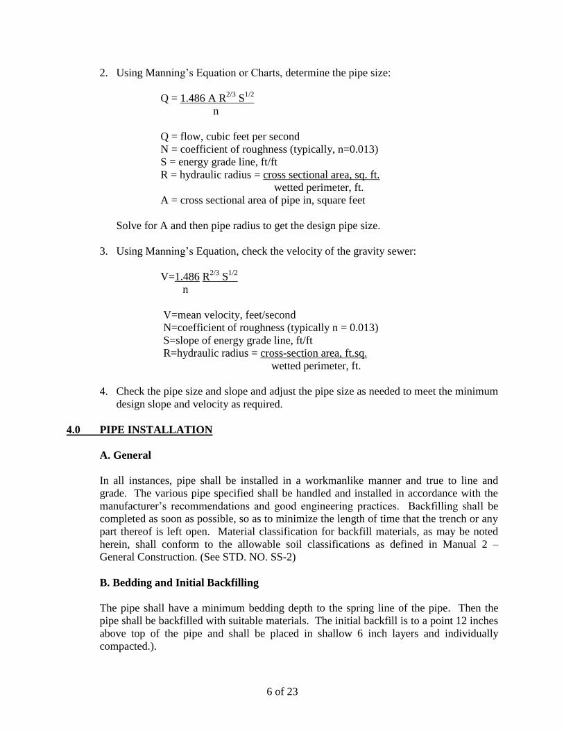
2. Using Manning’s Equation or Charts, determine the pipe size:
Q = 1.486 A R2/3
S1/2
n
Q = flow, cubic feet per second
N = coefficient of roughness (typically, n=0.013)
S = energy grade line, ft/ft
R = hydraulic radius = cross sectional area, sq. ft.
wetted perimeter, ft.
A = cross sectional area of pipe in, square feet
Solve for A and then pipe radius to get the design pipe size.
3. Using Manning’s Equation, check the velocity of the gravity sewer:
V=1.486 R2/3
S1/2
n
V=mean velocity, feet/second
N=coefficient of roughness (typically n = 0.013)
S=slope of energy grade line, ft/ft
R=hydraulic radius = cross-section area, ft.sq.
wetted perimeter, ft.
4. Check the pipe size and slope and adjust the pipe size as needed to meet the minimum
design slope and velocity as required.
4.0 PIPE INSTALLATION
A. General
In all instances, pipe shall be installed in a workmanlike manner and true to line and
grade. The various pipe specified shall be handled and installed in accordance with the
manufacturer’s recommendations and good engineering practices. Backfilling shall be
completed as soon as possible, so as to minimize the length of time that the trench or any
part thereof is left open. Material classification for backfill materials, as may be noted
herein, shall conform to the allowable soil classifications as defined in Manual 2 –
General Construction. (See STD. NO. SS-2)
B. Bedding and Initial Backfilling
The pipe shall have a minimum bedding depth to the spring line of the pipe. Then the
pipe shall be backfilled with suitable materials. The initial backfill is to a point 12 inches
above top of the pipe and shall be placed in shallow 6 inch layers and individually
compacted.).
7 of 23
C. Final Backfilling
The remaining or final backfill shall be suitable material. No rocks, boulders, or stone
shall be included in the backfill material for at least 2 feet above the top of the pipe. In
non-traffic areas, the backfill shall be placed in lifts not exceeding 12 inches and
compacted to 90% of optimum moisture density per AASHTO T-99. In traffic areas the
final backfill shall be placed and compacted in 6 inch layers, and compacted to 95% of
optimum moisture density per AASHTO T-99 to a point 12 inches below sub-grade. The
top 12 inches shall be compacted to 100% of optimum moisture density (AASHTO T-
99).
Where deemed necessary, the County Engineer may require compaction test on any or all
lifts of backfill placed in trenches under roadways. The cost for such test shall be
responsibility of the contractor.
5.0 DETAIL OF DESIGN
A. Minimum Size
Public sanitary sewer collection system, gravity piping, shall be a minimum of 8
inches in diameter.
B. Depth
1. A minimum of three 3 feet of cover, as measured from the crown of the pipe to
the finished grade, shall be provided for all sewers. Ductile iron pipe is required
for lines with less than 3 feet of cover. Proper bedding shall be provided where
sewers are subject to traffic bearing loads to develop design-supporting strength.
Additional protection shall be provided for sewers that cannot be placed at a depth
sufficient to prevent damage. The County Engineer shall determine the
acceptability of such installations.
2. Typically, the depth of gravity sewer mains shall be sufficient to serve adjoining
property or the first floor of existing homes, if possible. In isolated cases, the lot
owner may be required to provide a Low Pressure Sewer System to transport
sewage to the collection system.
3. Where unstable soil conditions are known to exist in the pipe zone, structural
design shall be based on a careful evaluation of the soil conditions and depth of
cover. Special structural designs (e.g. pilings with pipe support cradles, etc.) shall
be used where appropriate, and shall be detailed by the Engineer. A North
Carolina Professional Engineer shall design the trench excavation and pipe
support/protection systems.
8 of 23
C. Change In Pipe Size & Material
1. Where a smaller pipe joins a larger one within a manhole, the invert of the larger
sewer should be lowered sufficiently to maintain the same energy gradient.
Generally, aligning the crowns of the different size pipes is acceptable.
2. Sewer extensions shall be designed for projected flows, even when the diameter
of the receiving sewer is less than the diameter of the proposed extension at a
manhole, with special consideration of an appropriate flow channel to minimize
turbulence when there is a change in sewer size. Justification shall be provided
with the certification of completion and the construction plans, indicating that the
capacity of the downstream sewer will not be overloaded by the proposed
upstream installation. The County Engineer may require a schedule for
construction of future downstream sewer hydraulic conditions.
3. Pipe material should remain constant between manholes, unless the pipe is DIP
and SDR-26 and the County Engineer approves. For connection of DIP and SDR-
26 pipe (see STD. NO. SS-3).
4. At drop manholes, where invert separation exceeds 2 1/2 feet, the pipe material
shall be Ductile Iron or C900 PVC for interior drop. Pipe size between manholes
shall remain the same.
6.0 SERVICE LATERALS
1. A 4 inch service lateral may be tapped directly into the top quarter of 8, 10 and 12
inch mains or manholes. All service connections 6 inch and larger shall be made
into manholes. Connections to sewer mains 16 inch and larger shall only be made
at manholes. All individually owned structures shall be allowed only one sewer
tap unless otherwise approved by the County Engineer. (See STD. NO. SS-4, SS-
5 and SS-6 for details).
2. For a multiple family dwelling owned by a single individual or organization, the
number and location of service connections is to be approved by the County
Engineer with standard fees to be paid for each individual dwelling.
3. A maximum of three service connections may be installed into one manhole.
When the service connection is to be installed into an existing manhole, a boot
connector must be used. When joining ductile iron to other pipe materials, a rigid
connection designed specifically for transition of the two types of material is
required. When more than one service connection is installed in a manhole, the
connections shall be staggered vertically.
4. Plans for projects, which propose the creation of lots (subdivision) shall include
individual sewer taps to each parcel, including any residual parcels reserved for
future lots.
9 of 23
5. The size and locations of the service laterals shall be based on the anticipated use
of the lot, for which, the County Engineer approval shall be required. The
minimum lateral size shall be 4 inch laid on a minimum 1% grade. 6 inch lateral
grades shall be a minimum of 0.6%.
6. Service not terminated at manholes shall be installed at right angles to the gravity
sewer main using in-line wyes, or tapping service saddles on existing mains. The
wyes, saddles or taps shall be separated horizontally at least 5 feet, measured
along the pipe. See STD. NO. SS-5 for detail.
7. The lateral length shall not exceed 50 feet without additional cleanouts.
8. The service cleanout shall be placed at the edge of the right-of-way or permanent
easement and in no case shall be placed within a temporary easement. See STD.
NO. SS-6 for detail.
9. Lateral taps in manholes:
a. If a service is proposed in an existing manhole at a height of 2 1/2 feet or
greater above the invert, an inside drop shall be required for the service. See
STD. NO. SS-4 for detail.
b. The sewer lateral invert shall be a minimum of 1 inch above the shelf, or
sufficiently high enough to allow the installation of a flexible connector and
core into existing manhole.
10. Services Across Roads Wider Than Two (2) Lanes: Services across roads
wider than two (2) lanes shall have a 6” encasement pipe (casing) installed by the
customer, in addition to the Tap Fee, in order for Moore County to install a 4”
gravity service pipe inside the casing. The casing shall be installed by Bore &
Jack or Directional Bore and shall meet the standards in the General Construction
section of these specifications and extend from R/W to R/W.
7.0 SERVICE LATERAL MATERIALS
A. General Requirements
All sewer service laterals shall be constructed of PVC Schedule 40, or ductile iron
pipe, as specified herein, for all service laterals crossing beneath creeks or drainage
ways.
B. PVC Service Pipe & Fittings
PVC pipe and fittings for sewer laterals shall be Schedule 40 with cemented joints.
Laying lengths shall be 20 feet.
All cement shall be PVC Cement, all weather and have a trace color to allow for
visual indication of uniform application. The cement shall be preceded with a primer.
10 of 23
C. Service Saddles on Ductile Iron Pipe
Service saddles for connection of laterals to ductile iron sewer pipe shall be ductile
iron, 45-degree deflection, equipped with a single stainless steel clamp. The saddle
shall be furnished with adapters as required to properly receive the service pipe to be
used. A pipe cutter shall be used for tapping ductile iron pipe. In lieu of service
saddles, wye branches may be used on ductile iron sewers. SEE STD. NO. SS-5 for
detail.
D. Saddles for PVC Sewer Pipe (4-12 Inch Diameter Only)
Saddles for PVC shall conform to the requirements of ASTM D3034. The saddle
shall be equipped with two stainless steel clamps that are bolted to the saddle. The
saddle service branch shall stub slightly into the sewer main so that when installed,
the saddle shall not slip or rotate. The saddle shall be bedded and haunched with at
least 6 inch of select fill. Saddles shall be by Romac Industries, Inc. or equal. SEE
STD. NO. SS-5 for detail.
E. Service Cleanout Protector Boxes
Each service cleanout installed within any travel way area such as a driveway, alley,
or sidewalk shall be equipped with a cast iron protector box. The protector box shall
have a 9 5/8” diameter lid with the letter “S” cast into the lid. See STD. NO. SS-7 for
detail.
8.0 SEWER BACKWATER PREVENTION DEVICES
A. Backwater Relief Valve
All services shall have a Backwater Relief Valve and shall meet the following
requirements.
1. Automatic pop-up release to release sewage overflows outside the building
2. Vandal and tamper resistant center
3. Threaded for minimum 4” riser pipe
4. Constructed of PVC
5. Conforms to ASTM Standard D-2665
6. Safe in yard or high traffic areas
B. Backwater Check Valve
It is recommended that all connections have a Sewer Backwater Valve.
Any structure having a first floor elevation or basement floor elevation (if the base-
ment is connected to the sewer) which is lower than the elevation of manhole rim
immediately upstream of the site is considered to be susceptible to sewage backup. In
such cases, the sewer service lateral for the affected building shall be equipped with a
suitable sewage backwater valve as per the current NC Plumbing Code. The
backwater valve shall be located on private property in an accessible location for
maintenance. Any lots or structures where such backwater valves are required shall
11 of 23
be indicated on the construction drawings. The operation and maintenance of these
devices shall be the responsibility of the property owner.
9.0 GREASE TRAPS
All establishments, except private living quarters or dwelling units, engaged in the
preparation and/or serving of food shall install a grease trap in accordance with the State
and MCPW Ordinances.
All traps must be sized using approved formulas and calculations and must be submitted
to MCPW for approval.
The operation and maintenance of these devices shall be the responsibility of the property
owner.
Grease/Oil/Sediment Traps
All washing facilities, such as vehicle washes, car wash areas, etc. shall be equipped with
a grease/oil/sediment trap and trash basket. Sizing calculations shall be submitted with
the initial site/construction.
10.0 MANHOLES
A. General Features
1. Manholes installed in pavement shall have their cover set flush with finished
grade, and shall be located outside of designated parking spaces, where possible.
Whenever practical, manholes located in streets shall be located in the center of
the street.
2. Manholes installed in yards and landscaped areas shall have the top elevation set 6
inches above existing grade.
3. Manholes installed in outfalls or in natural areas shall have tops located 18 inches
above grade, or 2 feet above the 100-year flood elevation, whichever is greater.
4. Manholes should not be located in ditches, roadside swales, or gutter lines.
5. The minimum elevation difference between the centerline “invert in” and the
centerline “invert out” of manholes shall be 0.10 feet. Exceptions are:
1) When there is a change in flow direction of greater than 90 degrees, the
minimum difference shall be 0.20 feet;
2) When pipes of different sizes converge in a manhole, the inside tops of
the pipes shall be set at the same elevation; and
3) When grade is critical. Exceptions must be approved by the County
Engineer.
12 of 23
6. Hydrostatic uplift restraint shall be provided for manholes installed in areas that
are subject to floating/uplift.
7. The flow channel straight through a manhole shall be made to conform as closely
as possible in shape, and slope to the connecting sewer pipe. The channel walls
shall be formed or shaped to 3/4 of the height of the crown of the outlet sewer in
such a manner to not obstruct maintenance, inspection or flow in the sewer. See
STD NO. SS-8 for detail.
8. Vent Pipes shall have their opening at 2 feet above the 100 Year Flood Level or 5
feet above the Manhole, whichever is greater. See STD NO. SS-9 for detail.
9. “Doghouse” manholes shall be installed over existing sewer lines if an additional
main line connection is needed. See STD NO. SS-10 for detail.
10. For manholes 2 feet in height or less use a flat top with a standard frame and
cover. See STD NO. SS-11 for detail.
11. All manholes, outside pavement and yards, shall have a 66 inch tall Manhole
Warning Post. See STD NO. SS-12 for detail.
B. Location
1. The maximum distance between manholes, measured horizontal along the
centerline of the gravity sewer, shall be 425 feet.
2. Manholes shall be installed:
a. At the end of each main
b. At all changes in pipe grade
c. At all changes in nominal pipe size
d. At all horizontal changes in pipe alignment
e. At all intersections, unless otherwise approved by County Engineer
C. Diameter
The minimum interior diameter of gravity sewer manholes shall be specified
dependent upon the size of sewer main or depth of installation,
MH Diameter (feet) Main Size (inches) Depth of Installation (feet)
4 8 – 12 1 – 12
5 15 – 30 12 – 20
6 36 – 54 20 - plus
D. Drop Type
1. Vertical elevation drops through manholes should be limited to prevent turbulent
conditions. If the vertical elevation difference between the “invert in” and “invert
out” is: 1) greater than 6 inches, but less than 24 inches, a pipe slide is required to
13 of 23
prevent solids depositing; or 2) 24 inches and greater, a drop structure is required.
See STD NO. SS-13 for detail.
2. Inside drops are required for new lines using a 5 feet inside diameter manhole.
For existing 4 feet manholes, an inside drop may be permitted, as approved by
Engineer. Drop manholes shall be constructed with inside drops, secured to the
inside of the wall, and shall be positioned, in such a manner to allow for cleaning.
All Ductile Iron Pipe Fittings to be #401 coated. See STD. NO. SS-14 for detail.
E. Bench/Shelf
A bench/shelf shall be provided on each side of any manhole channel, when the pipe
diameter(s) are less than the manhole diameter. The bench/shelf shall be sloped not
less than 1 inch per foot and not greater than 2 inches per foot. The invert elevation
of any lateral sewer, service connection, or drop manhole pipe, shall be above the
bench/shelf surface elevation. Invert shall be located a minimum of 1 inch above the
bench/shelf.
Mortar used in manhole invert construction shall consist of one part Non-Shrink
Portland Cement and two parts sand. Portland Cement shall meet the requirements of
the latest ASTM Specifications C150, Type I. Sand used for mortar shall meet the
requirements of ASTM Specifications C144, latest edition. Mortar shall be mixed in
a clean, tight mortar box or in an approved mechanical mixer and shall be used within
45 minutes after mixing.
F. Water Tightness
1. Lift holes shall be sealed with non-shrinking mortar.
2. Inlet and outlet pipes shall be joined to the manhole with a Neoprene Rubber Boot
with Stainless Steel Jack (boot) or any watertight connection arrangement that
allows differential settlement of the pipe and manhole wall to take place.
Connections of new sewers to existing manholes shall be accomplished by
machine coring and the installation of a flexible connector (boot). The boot, if
used, shall be equal to Flexible Manhole Sleeve as manufactured by the Interpace
Corporation. See STD. NO. SS-15 for detail. The sealing system shall be
furnished by the manhole manufacturer.
3. Watertight Manhole Covers are to be used wherever the manhole tops may be
flooded by street runoff or high water. Locked manhole covers may be desirable
in isolated easement locations, where vandalism may be a potential or where lids
are subject to be flooded off. See Manhole Frame and Cover section for more
information. See STD. NO. SS-16 for detail.
Where a series of watertight manhole covers are used on a main line sewer for a
distance of 1,000 feet or more, vent pipes are required. See STD. NO. SS-9 for
detail.
14 of 23
4. Manhole sections shall have a standard tongue and groove joint with a Rubber O-
ring Gasket or Rope Mastic Seal, conforming to ASTM Standard C-443.
Conseal, Rub- R-Nek or equal may be used.
G. Precast Manholes
1. All new manholes shall be of precast concrete construction, unless approved by
the Engineer. See STD. NO. SS-17 for detail.
2. Precast concrete manholes shall be designed and manufactured in accordance with
ASTM C478. The manhole walls shall be a minimum of 5 inches thick and the
base slab shall have a minimum thickness of 6 inches. The minimum
compressive strength of the concrete shall be 4,000 psi. The manhole sections
shall have reinforcement as required to provide resistance to the hydrostatic and
passive earth pressures to which they will be subjected, and to provide adequate
resistance to temperature and shrinkage cracking.
3. All manholes shall be equipped with a flexible watertight connection and sealing
system for all pipe penetrations.
H. Manhole Frame and Cover
Manhole ring and cover shall meet the requirements of ASTM Specifications for
Gray Iron Castings, latest edition for Class 30. Minimum weight for the frame and
cover shall be 190 lbs. and 120 lbs. respectively. The cover shall have the words
"SANITARY SEWER" cast in and be perforated with 2 – 1 inch diameter vent/pick
holes. Standard frame & covers shall be equivalent to Vulcan V-1384, US Foundry
669-KL or approved equal. Watertight manholes shall be Vulcan V-2384, US
Foundry 361-CJ-BWT or approved equal. Where deemed necessary in low areas of
streets, solid manhole covers may be required by the County Engineer to prevent
surface water inflow into the sewer. Flush type rings shall be used and cast into flat
top manholes. See STD NO. SS-16 and SS-18 for details.
I. Stone for Stabilization of Trench Foundation
In all areas of unsuitable soil and/or organics, the pipe shall be bedded in at least 12
inches of No. 57 stone with an additional 12 inches of stone above the crown of the
pipe, except for ferrous pipe.
J. Special Coating Requirements
Manholes located at the terminus of any gravity or sewer force main (other than from
an individual residential grinder pump force main) shall have an interior coating
thickness of 100 mils of 100% solids epoxy, such as Raven 405, Cor-Cote SC,
PerpetuCoat or approved equal. All epoxy coatings shall be installed per
manufacturer’s recommendations, following all surface preparation steps required.
MCPW reserves the right to require interior coating of additional manholes
downstream of the receiving manhole of up to 1,000 feet as recommended by the
County Engineer.
15 of 23
K. Grade Adjustment Rings
Where deemed necessary in low areas, precast concrete rings may be required by the
County Engineer to prevent surface water inflow into the sewer. Grade adjustment
rings shall be made of reinforced concrete, comply with ASTM C 478 and be free
from cracks, voids, and other defects. Set concrete rings with bituminous jointing
material in trowelable or rope form. Tapered adjusting ring thickness ranges from 1/2
inch to 3 inches. Install grade adjustment rings on clean, flat surfaces according to
the manufacturer's recommendations with the proper bituminous jointing material.
Ensure the inside diameter of the adjustment ring is not be less than the inside
diameter of the manhole frame. Construct manholes with at least one adjustment
ring, totaling 4 inches minimum and 12 inches maximum for new manholes and 4
inches minimum and 16 inches maximum for existing manholes
11.0 STREAMS AND OTHER WATER BODIES
A. Stream Crossing
Crossing of streams shall be minimized and as nearly perpendicular to the stream as
possible. Streams shall be protected in accordance with erosion control plans and
specifications and shall be stabilized immediately after construction is completed on
the segment of crossing line. Depending on actual cover, stream width, flow
conditions and soil conditions, the sewer pipe may require special anchorage to
prevent flotation and/or washout. Each crossing must be evaluated individually. Pipe
for submerged stream crossings shall be restrained by means approved by the County
Engineer.
1. Cover Depth
a. Sewer paralleling streams/creeks shall be designed to be below the streambed
elevation, such that lateral connections will be protected as described herein.
b. The top of all sewers entering or crossing streams shall be at a sufficient depth
below the natural bottom of the streambed to protect the sewer line and meet
all regulations of permitting agencies.
i. 1 foot of cover where the sewer is located in rock
ii. 3 feet of cover in other material unless ductile iron pipe is
specified; in which case, a minimum of 1 foot of cover
iii. In major streams, a minimum of 3 feet of cover
iv. In paved stream channels, the top of the sewer line should be
placed below the bottom of the channel pavement.
2. Horizontal Location
a. Sewers located along streams, lakes or impoundments, shall be located outside
of the stream and/or creek bank or sufficiently removed to provide for future
possible stream widening, to prevent siltation of the stream during
construction and to meet all regulations by permitting agencies.
16 of 23
b. Sewers shall not be installed under any part of an impoundment and/or earthen
dam, without specific MCPW approval. Plans shall require review, and
approval by NCDWQ Dam Safety Section.
c. Sewers crossing streams shall be perpendicular (90 degrees) as practical to the
streambed and in no case at an angle less than 75 degrees or greater than 105
degrees to the stream unless approved by County Engineer.
d. Edge of the construction corridor shall not be closer than 10 feet to a stream.
e. Intermittent or permanent stream crossing shall not have joints connected
within the stream channel or within 2 feet of banks, unless approved by
County Engineer.
f. Construction corridor limited to 40 feet in width in wetlands and across stream
channels. Wetland delineation shall be clearly shown on the plans.
3. The sewer outfalls, headwalls, manholes, gate boxes or other structures shall be
located so they do not interfere with the free discharge of flood flows of the
stream.
4. Materials
a. Sewer entering or crossing streams shall be constructed of ductile iron
material pipe with mechanical joints, and shall be constructed to remain
watertight, free from changes in alignment or grade.. Material used to backfill
the trench shall be stone, coarse aggregate, washed gravel, or other materials
which will not readily erode, cause siltation, damage to pipe during
placement, or corrode the pipe.
b. Measures shall be taken to prevent fresh concrete from coming in contact with
waters of the state.
c. Placement of rip-rap is restricted to the stream bottom, and cannot be above
normal stream bottom; banks directly impacted and only below normal high
water level.
d. No fertilizer shall be placed within 10 feet of a stream.
B. Aerial Crossings
1. Proper joint technology, such as flanged or restrained, adequate supports prevent
excessive flexion, or a combination of both, shall be provided for all aerial pipe
crossing. Supports shall be designed to prevent frost heave, overturning, and
settlement.
2. Supports shall be designed to withstand the hydrodynamic effects of the stream
flow pressure using the following formula:
P = 1.5K(VxV)
Where:
1.5-safety factor against overturning
P=pressure, psf
V=velocity of water, fps
17 of 23
K = 4/3 for square ends, 1/2 for angle ends when angle is 30 degrees or less and
2/3 for circular piers. (Dimensionless)
If it is probable that the aerial pipe could be submerged by the stream flow, the
effects of the flow pressure on the pipe shall also be taken into account when
computing pier-overturning moments. For aerial stream crossings, the impact of
flow waters, and debris shall be considered.
3. H-Piles shall be driven to resistance by an approved hammer developing not less
than 7,500 ft-lbs of energy per blow. The load capacity of each pile shall be
determined by the following formula:
Ra = 2E/(S+0.3)
Where:
Ra=Safe load (lbs)
E=Energy per blow (ft-lbs)
S=Final penetration per blow (inches); (average of last 6 blows)
4. Protection against freezing, such as, insulation and increased slope, shall be
provided. Expansion jointing shall be provided. Expansion jointing shall be
provided between above ground and below ground sewers. Where buried sewers
change to aerial sewers, special construction techniques shall be used to minimize
heaving.
5. The bottom of the pipe should be placed no lower than the elevation of the 100-
year flood.
6. Small streams or ditches that can be spanned with a single joint of ductile iron
pipe may be anchored with concrete collars provided the collars are below grade.
7. Sewer Pipe to be encased within 35,000 psi Steel Pipe.
8. See STD NO. SS-19 and SS-20 for detail examples.
C. Anti-Seepage Collars
In areas where the sewer trench is located in jurisdictional wetlands and has the
potential to drain wetlands, anti-seepage collars shall be installed. A water quality
and wetlands (401/404) permit shall be required. An anti-seep collar shall be placed
at the downstream wetland boundary and every 150 feet until the utility exits the
wetland. Wetland crossings that are open cut and less than 150 feet long do not
require anti-seep collars unless specifically required by County Engineer.
18 of 23
12.0 PIPE MATERIALS
A. Pipe Size and Types
Pipe Type Pipe Size (inches
DIP (Depths 12 ft & greater) all sizes
DIP Ductile Iron Pipe, Class 350 12 & smaller
DIP Ductile Iron Pipe, Class 250 16 & larger
PVC C-905, Class 200, DR21 14 to 36
PVC Polyvinyl Chloride SDR-26 8 to 16
PVC Schedule 40 (Service) Not Foam Core 4 & 6
SP Steel Pipe, 35,000 psi (Encasement) all sizes
No encasement for taps under Secondary Roads
Encasement under Secondary Roads & Town Streets if noted
Encasement under Primary roads
Encasement under Railroads
B. Ductile Iron Sewer Pipe
All ductile iron pipes shall be designed as per ANSI/AWWA C-151/A21.50-02.
Pipe joints shall be of the push-on type with rubber gaskets as per ANSI/AWWA C-
111/A21.11-07. Pipe lining shall be cement-mortar, on the interior, with an external
coat of bituminous material, all in accordance with ANSI/AWWA C-104/A21.4-03.
The diameter, class or nominal thickness, net weight without lining, and casting
period shall be clearly marked on each length of pipe. Additionally, the
manufacturer’s mark, Country where cast, year in which the pipe was produced and
the letters “DI” or “Ductile” shall be cast or stamped on the pipe.
Ductile iron pipe shall be manufactured by U.S. Pipe, American or McWane and shall
be furnished in 20 foot or 18 foot lengths.
C. PVC Gravity Sewer Pipe
PVC pipe shall be rigid polyvinyl chloride with integrally formed, factory fabricated
bell with “slip” joints and rubber gaskets conforming to AWWA C-111. It shall be
suitable for all conditions imposed by plan locations and for a maximum working
pressure of 200 psi. Pipe shall be type 1, Grade 1 made from clear virgin material
shall conform to the requirements of ASTM D-1784 and green in color. All pipes
shall bear the manufacturer’s name, diameter, pipe class and date produced. Pipe to
conform to SDR 26. Where restrained joints are indicated Mega-Lugs or Grip rings
shall be used.
D. Steel (Casing) Pipe
Steel encasement pipe shall be welded or seamless, consisting of Grade "B" steel with
minimum yield strength of 35,000 psi and manufactured in accordance with
19 of 23
ASTM A139.
The pipe thickness shall be as specified on the encroachment agreement or approved
plans, and the ends shall be beveled and prepared for field welding of the
circumferential joints. For pipe thickness, see Manual 2, General Construction.
Spacers – Steel, epoxy coated “spiders” shall be provided. Provide one spacer in the
center of pipe and one spacer on each end of the same pipe stick.
Carrier pipe shall be Ductile Iron Pipe. Carrier pipe shall be installed using boltless
restraining gaskets. Boltless restraining gaskets shall be “Field-Lok”, “Fast-Grip”,
“Gripper Gasket” or approved equal.
13.0 INSPECTION AND TESTING OF GRAVITY SEWERS
A. CCTV Inspection of Pipeline Interior, Manholes and Lift Stations
All pipelines interior, manholes and lift stations shall be inspected after installation.
See CCTV INSPECTION OF GRAVITY SEWERS section.
B. Low Pressure Air Tests
All newly constructed Sewer Lines shall be air tested in the presence of the County
Engineer or representative.
The low pressure air testing shall be conducted in accordance with ASTM C828.
Prior to testing, the sewer line shall be clear of debris and flushed with water as
necessary. The line shall be plugged and the plugs shall be securely braced to prevent
slippage. The line shall be pressurized with air to 5 psi and allowed to stabilize for a
period for 5 minutes and hold.
Should the section of the pipe being tested fail to meet these requirements, the source
of leakage shall be determined and repaired. The section shall then be retested until it
is deemed to be acceptable.
The Contractor shall furnish all plugs, compressors, hose, gauges, etc., as required to
conduct the low-pressure air test. All testing equipment shall be approved by the
County Engineer.
C. Infiltration Tests
Portions of the sewer lines installed in areas that exhibit a higher ground water table
(in the trench) during construction shall be tested for infiltration. The portions of the
line to be infiltration tested shall be determined by the County Engineer.
The portion of the sewer line designated by the County Engineer shall be tested for
infiltration by installing a V-notch weir or other suitable measuring device in the
downstream end of the pipe to be tested. When a steady flow occurs over the weir,
the rate of flow (infiltration) shall be measured. The rate thus measured shall not
exceed 100 gallons per 24 hours per inch of sewer pipe diameter per mile of pipe.
20 of 23
Weirs and other equipment required for infiltration tests shall be furnished by the
Contractor and the tests shall be performed in the presence of the County Engineer.
Should the infiltration tests reveal leakage in excess of the allowable, the leaking
joints shall be re-laid if necessary or other remedial construction shall be performed
by and at the expense of the Contractor. The section of sewer thus repaired shall then
be retested to determine compliance with the Specifications.
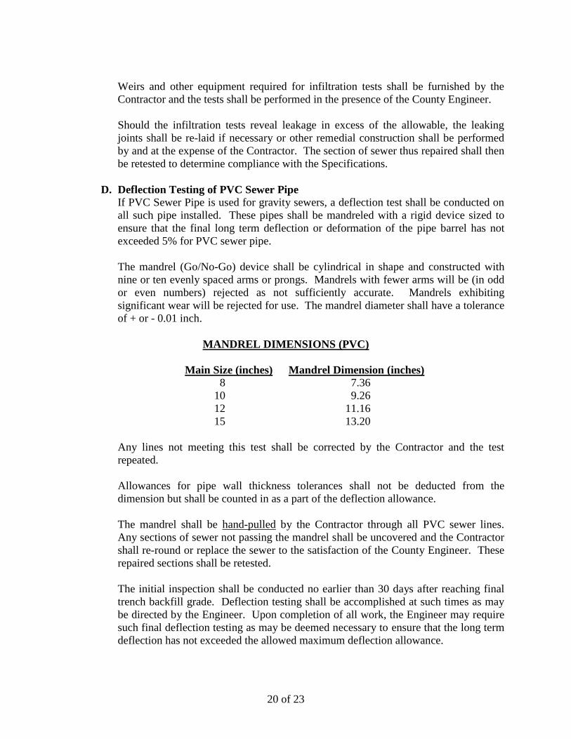
D. Deflection Testing of PVC Sewer Pipe
If PVC Sewer Pipe is used for gravity sewers, a deflection test shall be conducted on
all such pipe installed. These pipes shall be mandreled with a rigid device sized to
ensure that the final long term deflection or deformation of the pipe barrel has not
exceeded 5% for PVC sewer pipe.
The mandrel (Go/No-Go) device shall be cylindrical in shape and constructed with
nine or ten evenly spaced arms or prongs. Mandrels with fewer arms will be (in odd
or even numbers) rejected as not sufficiently accurate. Mandrels exhibiting
significant wear will be rejected for use. The mandrel diameter shall have a tolerance
of + or - 0.01 inch.
MANDREL DIMENSIONS (PVC)
Main Size (inches) Mandrel Dimension (inches)
8 7.36
10 9.26
12 11.16
15 13.20
Any lines not meeting this test shall be corrected by the Contractor and the test
repeated.
Allowances for pipe wall thickness tolerances shall not be deducted from the
dimension but shall be counted in as a part of the deflection allowance.
The mandrel shall be hand-pulled by the Contractor through all PVC sewer lines.
Any sections of sewer not passing the mandrel shall be uncovered and the Contractor
shall re-round or replace the sewer to the satisfaction of the County Engineer. These
repaired sections shall be retested.
The initial inspection shall be conducted no earlier than 30 days after reaching final
trench backfill grade. Deflection testing shall be accomplished at such times as may
be directed by the Engineer. Upon completion of all work, the Engineer may require
such final deflection testing as may be deemed necessary to ensure that the long term
deflection has not exceeded the allowed maximum deflection allowance.
21 of 23
The mandrel shall be approved by the County Engineer. Deflection test must be
completed in the presence of the County Engineer or representative.
E. Exfiltration Tests
In addition to infiltration test the Engineer may require an exfiltration test for all
sewers and manholes that are exposed (i.e. aerial). Each segment of pipe and
manholes shall be plugged and filled with water to a depth no less than the rim of the
downstream manhole for a period of 1 hour. No leakage shall be allowed. This work
shall be carried out beginning at the high end of the aerial segment in order to
minimize the amount of water necessary for testing. Testing may be required before
backfilling by the County Engineer and must be completed in the presence of the
Engineer or representative.
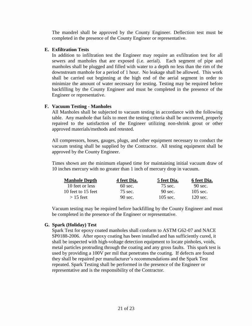
F. Vacuum Testing - Manholes
All Manholes shall be subjected to vacuum testing in accordance with the following
table. Any manhole that fails to meet the testing criteria shall be uncovered, properly
repaired to the satisfaction of the Engineer utilizing non-shrink grout or other
approved materials/methods and retested.
All compressors, hoses, gauges, plugs, and other equipment necessary to conduct the
vacuum testing shall be supplied by the Contractor. All testing equipment shall be
approved by the County Engineer.
Times shown are the minimum elapsed time for maintaining initial vacuum draw of
10 inches mercury with no greater than 1 inch of mercury drop in vacuum.
Manhole Depth 4 feet Dia. 5 feet Dia. 6 feet Dia.
10 feet or less 60 sec. 75 sec. 90 sec.
10 feet to 15 feet 75 sec. 90 sec. 105 sec.
> 15 feet 90 sec. 105 sec. 120 sec.
Vacuum testing may be required before backfilling by the County Engineer and must
be completed in the presence of the Engineer or representative.
G. Spark (Holiday) Test
Spark Test for epoxy coated manholes shall conform to ASTM G62-07 and NACE
SP0188-2006. After epoxy coating has been installed and has sufficiently cured, it
shall be inspected with high-voltage detection equipment to locate pinholes, voids,
metal particles protruding through the coating and any gross faults. This spark test is
used by providing a 100V per mil that penetrates the coating. If defects are found
they shall be repaired per manufacturer’s recommendations and the Spark Test
repeated. Spark Testing shall be performed in the presence of the Engineer or
representative and is the responsibility of the Contractor.
22 of 23
14.0 CCTV INSPECTION OF GRAVITY SEWERS
A. Qualifications
All CCTV operator(s) responsible for direct reporting of sewer condition shall be
certified by National Association of Sewer Service Companies (NASSCO) and Pipeline
Assessment and Certification Program (PACP) and have previous experience in
surveying, processing, and interpretation of data associated with CCTV
surveys/inspections.
B. Submittals The Owner’s designated representative on site shall certify receipt of the daily record.
The Contractor shall submit a copy of the CCTV DVD’s and a copy of Inspection Report
incorporating a summary statistical breakdown of defects and main findings
C. Equipment The television equipment used for the survey shall be one specifically designed and
constructed for such a survey, including all-terrain conditions. The surveying/inspecting
equipment shall be capable of surveying/inspecting a length of sewer up to at least 1,000
ft. when entry into the sewer may be obtained at each end and up to 750 ft. where a self-
propelled unit is used, where entry is possible at one end only.
The CCTV camera lens head shall be positioned centrally (i.e. in prime position) within
the sewer along the axis of the sewer. A positioning tolerance of ± 10% of the vertical
sewer dimension shall be allowed when the camera is in prime position.
The camera shall have suitable illumination capable of providing an accurate, uniform
and clear record of the sewer’s internal condition of the entire periphery of the pipe. In-
sewer lighting shall produce a minimum of 1.0 LUX illumination. The camera shall be
able to operate in 100% humidity. The camera, television monitor and other components
of the video system shall be capable of producing a minimum 700 line resolution color
video picture. The contractor shall maintain the camera in clear focus at all times. The
video camera shall include a titler.
D. Digital Video
DVD or Thumb Drive shall be supplied for all television surveys. All DVDs or Thumb
Drives shall be submitted to the Owner and will become the property of the Owner.
Digital video logs shall also be provided with the DVDs or Thumb Drives.
E. Execution
The camera shall be moved through the line at a moderate rate, stopping whenever
necessary to permit proper documentation of any defects or infiltration and inflow. In no
instances shall the camera move at more than 30 linear feet per minute.
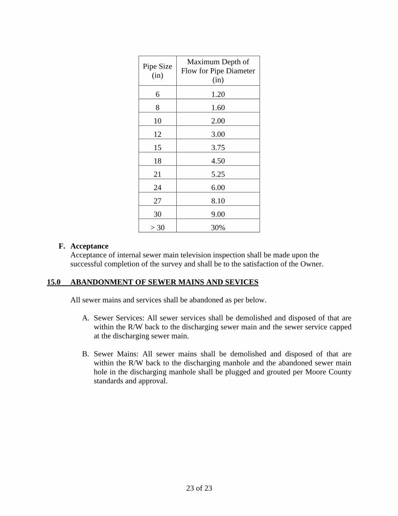
When performing television inspection, depth of flow shall not exceed that shown below
for the respective pipe sizes, as measured in the downstream manhole.
23 of 23
Pipe Size
(in)
Maximum Depth of
Flow for Pipe Diameter
(in)
6 1.20
8 1.60
10 2.00
12 3.00
15 3.75
18 4.50
21 5.25
24 6.00
27 8.10
30 9.00
> 30 30%
F. Acceptance
Acceptance of internal sewer main television inspection shall be made upon the
successful completion of the survey and shall be to the satisfaction of the Owner.
15.0 ABANDONMENT OF SEWER MAINS AND SEVICES
All sewer mains and services shall be abandoned as per below.
A. Sewer Services: All sewer services shall be demolished and disposed of that are
within the R/W back to the discharging sewer main and the sewer service capped
at the discharging sewer main.
B. Sewer Mains: All sewer mains shall be demolished and disposed of that are
within the R/W back to the discharging manhole and the abandoned sewer main
hole in the discharging manhole shall be plugged and grouted per Moore County
standards and approval.