Embed Size (px)
Citation preview

Water Standard Details Index 300.0 – Water Plan General Notes
300.1 – Connection to Water Main with Tapping Tee & Valve
300.2 – Connection to Water Main Cut In‐Line & One Valve
300.3 – Connection to Water Main In‐Line Tee & Two Valves
300.4 – Connection to Water Main In‐Line Tee & Three Valves
300.5 – Connection to Water Main Existing Tee or End Line Cap
300.6 – Poly Pig Station for Cleaning of Water Mains
310.1 – Fire Hydrant Assembly
310.3 – Hydrant Marker Layout
320.1 – ¾” and 1” water Service
320.2 – 1 ½” and 2” Water Service Located in Planting Strip
320.3 – 2” and 1 ½” Water Service Located in Right of Way Behind Sidewalk
320.4 – 3”, 4”, & 6” Compound Domestic Water Meter Assembly
330.1 – Valve Box, Marker & Operating Nut Extension
330.2 – Concrete Blocking for Horizontal and Downward Vertical Bends
330.3 – Concrete Blocking for Vertical Fittings
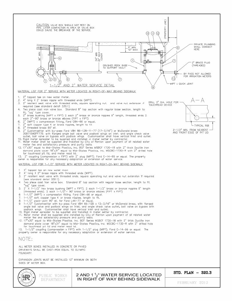
330.5 – Shackle Rods and Tie Bolts
340.1 – 2” Blow‐Off Permanent Assembly
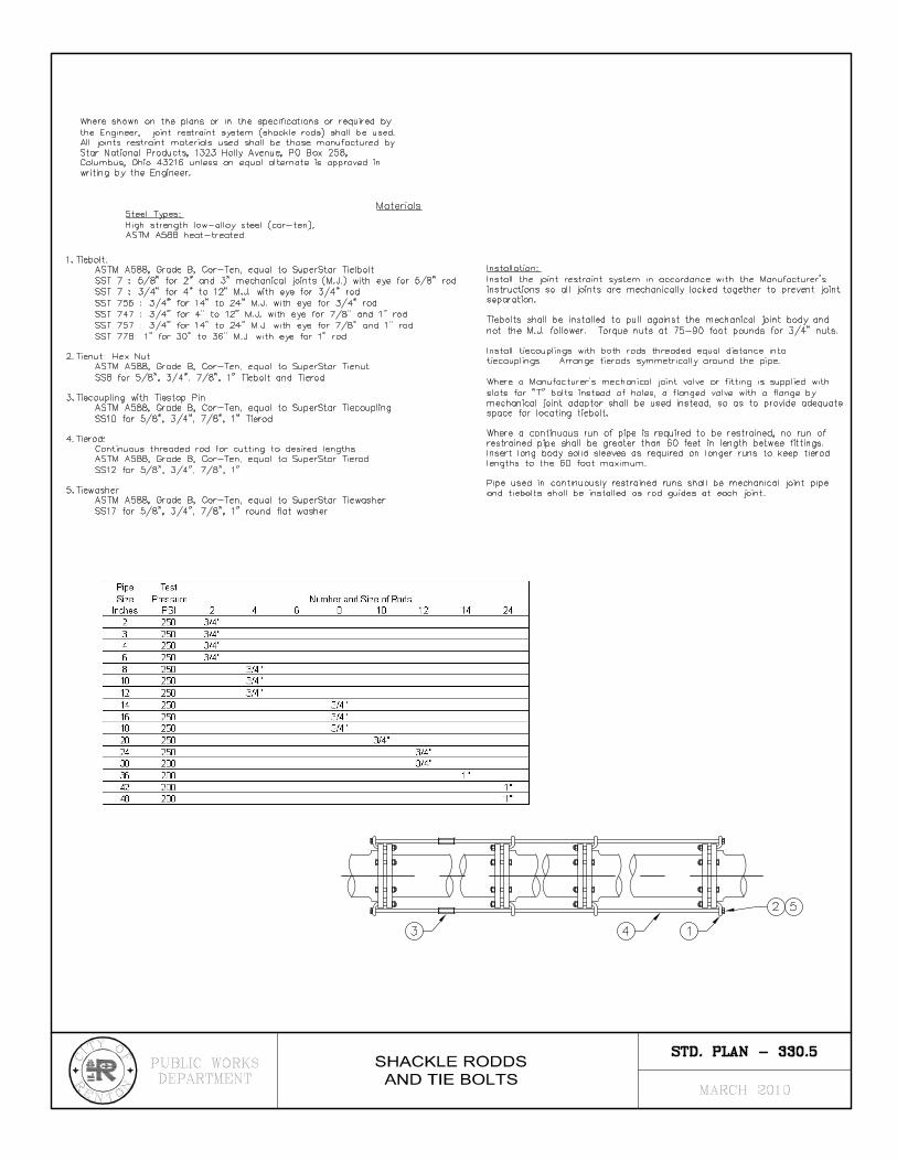
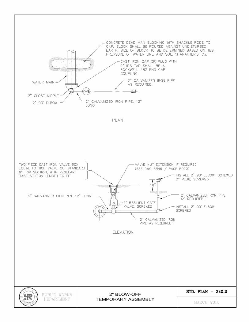
340.2 – 2” Blow‐Off Temporary Assembly
340.3 – 1” Air & Vacuum Release Assembly
340.4 – 2” air & Vacuum Release Assembly
340.5 – ¾” & 1” Individual Pressure Reducing Valve Assembly
340.6 – Pressure reducing Station In‐Vault Standard
340.7 – Pressure Reducing Station In‐Vault with In‐Line Valve
340.8 – ¾” to 2” Double Check Valve Assembly for Irrigation or Residential Fire Sprinkler
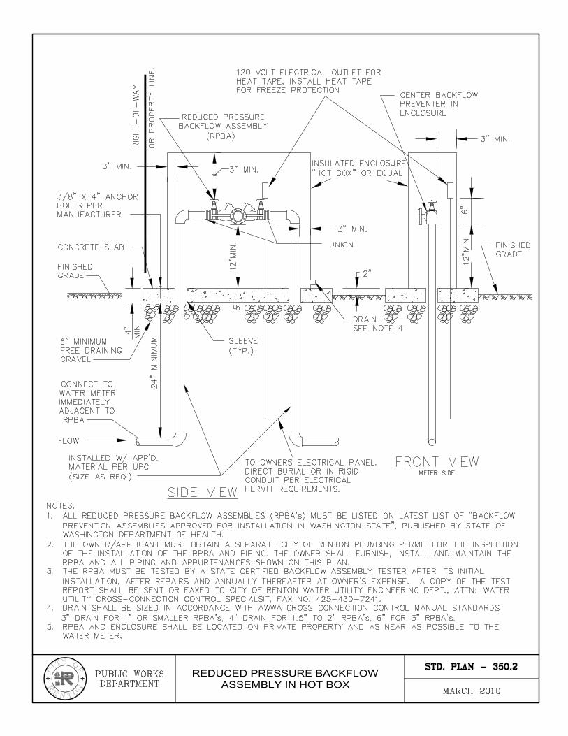
350.2 – Reduced Pressure Backflow Assembly in Hot Box
360.1 – 4” DDCV Assembly with Standpipe Outside Connection
360.2 – 6”, 8”, & 10” Double Detector Check Assembly with Standpipe Outside Installation
360.3 – 4” DDCV Assembly without Standpipe Outside Installation
360.4 – 6”, 8”, & 10” Double Detector Check Assembly without Standpipe Outside Installation
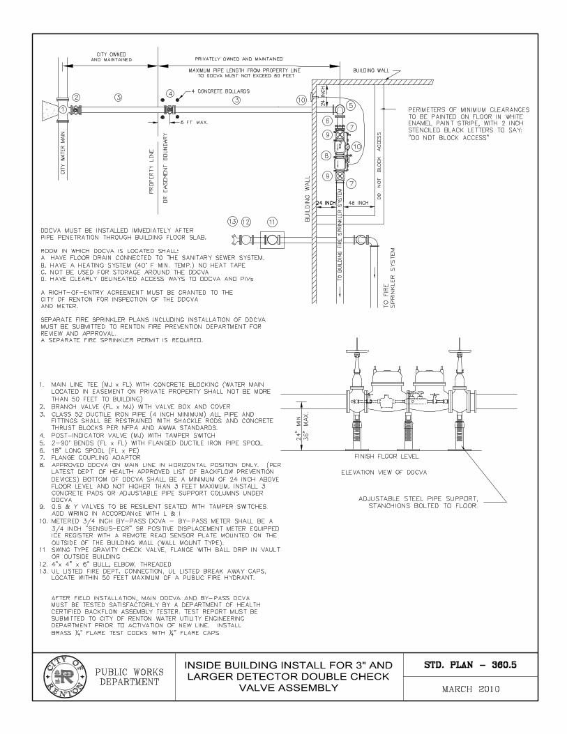
360.5 – Inside Building Install for 3” and Larger Detector Double Check Valve Assembly


Utility Specifications
Water Utility Notes and Specifications
THESE NOTES SHALL APPEAR ON PROJECTS FOR THE WATER UTILITY.
1. All work material shall be in conformance with the standards and specifications of the City of Renton Planning/Building/Public Works Department and the latest edition of the WSDOT/APWA Standards and Specifications, as approved and modified by the City of Renton in the Renton Standard Plans & Specifications. A set of approved plans shall be kept on site at all times during construction.
2. The hours of work in the street right of way shall be limited to 8:30 AM to 3:30 PM on weekdays unless otherwise approved in writing by the Public Works Department at (425) 430-7301. The Police Department, Fire Department, and 911 shall be notified 24 hours in advance of any work in the right of way.
3. All locations of existing utilities shown are approximate and it shall be the contractor’s responsibility to verify the true and correct location so as to avoid damage or disturbance. For utility locates call 48-hour locators 800-424-5555.
4. An approved Traffic Control Plan is required to be submitted at the Pre-Construction meeting.
5. Datum for Vertical Control shall be North American Vertical Datum 1988 Meters, and for Horizontal Control shall be North American Datum 1983/1991 Meters unless otherwise approved by the City of Renton Public Works Department. Reference benchmark and elevations are noted on the plans.
6. All watermain pipe is to be cement lined ductile iron pipe conforming to AWWA C110 and C111 or latest revision, thickness Class 52. Cement mortar lining and seal coating shall conform to AWWA C104 or latest revision. Pipe joints to be push-on or mechanical joint. Bedding to be Class C. All ductile iron pipe and fittings shall be polyethylene wrapped per ANSI/AWWA C105/A21.5-93 Standards.
7. Cast iron and ductile iron fittings shall be cement lined, pressure rated as noted on plans, and in accordance with ANSI/AWWA C110/A21.10-87. Cement lining shall be in accordance with ANSI/AWWA C104/421/4-90. If fittings are 3 to 12 inches in diameter and have mechanical joints, the fittings shall in accordance with either ANSI/AWWA C110-A21.10-87 or ANSI/AWWA C153/A21.53-94. Three (3) inch to 12 inch diameter fittings, which have mechanical joints and/or flanged joints, shall be in accordance with ANSI/AWWA C110/A21.10.87 or a combination of ANSI/AWWA C110/A21.10.87 and ANSI/AWWA C153/A21.53-94 such that the portion of the fitting with a mechanical joint(s) may be with ANSI/AWWA C153/A21.53-94 and that portion of the fitting with flanged joint(s) shall be in accordance with AWWA C110/A21.10-87. Acceptance testing in accordance with section 53.53 of ANSI/AWWA section 10-4.3 of ANSI/AWWA C110/A21.10-87 shall be obtained by the contractor and transmitted to the owner.
8. Gate valves shall be iron body, bronzed-mounted, double disc with bronze wedging device and O-ring stuffing box (AWWA C500) or of resilient seated type (AWWA C509).

Utility Specifications
Valves shall be designed for a minimum water operating pressure of 200 psi. Gate valves shall be Clow List 14, Mueller Company NO. A2380 or M & H.
9. Fire hydrants shall be Corey type (opening with the pressure) or compression type (opening against pressure) conforming to AWWA C-502-85 with a 6 inch mechanical joint inlet and a main valve opening (M.V.O.) of 5-1/4 inch, two 2-1/2 inch hose nozzles with National Standard Threads 7-1/2 threads per inch and one 4 inch pumper nozzle with the new Seattle Pattern 6 threads per inch, 60 degrees V. Threads: outside diameter of male thread 4.875 and root diameter 4.6263. Hydrants shall have a 1-1/4 inch pentagon operating nut opened by turning counter clockwise (left).
10. The two 2-1/2 inch hose nozzles shall be fitted with cast iron threaded caps with operating nut of the same design and proportions as the hydrant stem nut. Caps shall be fitted with suitable neoprene gaskets for positive water tightness under test pressures.
11. The 4 inch pumper nozzle shall be fitted with a Storz adapter, 4 inch Seattle Thread x 5 inch Storz. Storz adapter shall be forged and/or extruded 6061-T6 aluminum alloy, hardcoat anodized. Threaded end portion shall have no lugs and two set screws 180 degrees apart. Storz face to be metal, no gasket to weather. Storz cap to have synthetic molded rubber gasket, and shall be attached to hydrant adapter with 1/8 inch, coated, stainless steel, aircraft cable.
12. Fire hydrants shall be painted with two coats of paint. Preservative paint number 43-655 safety yellow or approved equal.
13. Pumper connection to face roadway assembly.
14. Fire hydrants shall be installed per City of Renton Standard Detail for fire hydrants, latest revision.
15. All watermains 10 inches and smaller to maintain a minimum cover of 36 inches below finish grade. All watermain 12 inches and larger shall be at a minimum of 48 inches below finish grade. Where utility conflicts occur, watermains are to be lowered to clear.
16. All watermains 6 inches and larger in diameter shall be cleaned with pipe cleaning “PIGS” prior to disinfection. The “Poly pigs” shall be Girard Industries Aqua Swab-AS or approved equal, 2 lb/cu. ft. density foam with 90A durometer urethane rubber coating on the rear of “PIG” only.
17. “PIGS” shall be cylinder shaped with bullet nose or square end. The contractor will perform the cleaning operation.
18. All watermains and services shall be pressure tested to a minimum of 200 psi or 150 psi over operating pressure, in accordance with the specifications of the City of Renton and the Washington State Health Department. All pressure testing shall be done in the presence of a representative of the City of Renton. The quantity of water lost from the main shall not exceed the number of gallons per hour as listed in City of Renton

Utility Specifications
Standard Plans & Specifications 7-11.3(11). The loss in pressure shall not exceed 5 psi during the 2 hour test period.
19. All watermains and services shall be disinfected by the injection of a 50 ppm (minimum concentration) chlorine/water solution. Dry Calcium Hypochlorite shall NOT be placed in the pipe as laid. Chlorine shall be metered/injected in accordance with Section 7-11.3(12)E or 7-11.3(12)F of the Standard Specifications referenced above.
20. A pre-construction conference is required prior to any construction. A minimum of five (5) working days notice is required for scheduling.
21. Twenty-four (24) hours notice will be required prior to starting new construction.
22. It shall be the contractor’s responsibility to secure all necessary permits prior to starting construction.
23. Installation of corporate stops, water services, lines and meters shall not be done until all service agreements, meter applications, construction permits, and payment of fees have been made to the City of Renton.
24. All connection to existing mains is to be accomplished by the City of Renton, except wet taps, which may be made by approved wet tap contractors with prior approval from the Public Works Department. All necessary excavation and materials are to be supplied by the contractor and be on-site prior to City notifications.
25. Inspection will be accomplished by a representative of the City of Renton. It shall be the contractor’s responsibility to notify Development Services twenty four (24) hours in advance of backfilling all construction. The contractor, as well as the engineers, shall keep as-built drawings.
26. Contractor to provide plugs and temporary blow-off assemblies for testing and purity acceptance prior to final tie-in.
27. All joint restraint systems (shackle rods, nuts, bolts, etc.) shall be as manufactured by the Star Manufacturing Company of Columbus Ohio, or equal, approved in writing by the Public Works Department.
28. Asphalt and concrete street paving shall be sawcut to a minimum depth of two (2) inches. Oil mat streets may be spade cut. All surface concrete, pavement, sidewalks, curb, gutters, and driveway approaches shall be sawcut to a minimum depth of two (2) inches or removed to an existing expansion joint.
29. A temporary cold mix asphalt patch shall be placed on the day of initial excavation with a permanent, sealed patch to be placed, to City of Renton policy, within 10 days. Call for subgrade inspection prior to placement of final patch. *
30. For City projects such as telemetry conduit, the PVC pipe used shall be All chemical process lines shall be schedule 80 PVC pipe. Schedule 40 in unimproved areas and schedule 80 PVC pipe under improved areas.