Embed Size (px)
Citation preview

March 1, 1999 / Vol. 24, No. 5 / OPTICS LETTERS 333
Wave-front control and aberration correction with adiffractive optical element
Salman Noach, Yoel Arieli, and Naftali Eisenberg
Department of Electro-optics, Jerusalem College of Technology, Jerusalem 91160, Israel
Received August 24, 1998
A method that permits aberration correction and wave-front reshaping with a diffractive optical element(DOE) is described. Two aligned DOE’s made of two different dispersive materials are used. The differentdispersions of the two materials in addition to freedom in choosing their thicknesses enables the chromaticaberration and the wave fronts to be manipulated. Design and simulation of such DOE’s are described. 1999 Optical Society of America
OCIS codes: 010.7350, 090.1000, 090.1970.
A new method for designing a diffractive optical ele-ment (DOE) is described that permits variable controlof the optical path length for different wavelengths.This approach is an expansion of the method for elimi-nating the chromatic aberration in an achromaticDOE, published earlier.1 This method can be appliedfor aberration correction and solution of dispersionproblems.
The achromatic DOE is an array of phase distri-bution pixels. The pixel is composed of two DOE’smade from different dispersive materials, as depictedin Fig. 1. With suitable thicknesses sd1, d2d each pixelprovides the exact phase value for l0, the wavelengthin the middle of a selected spectrum, with minimumphase aberration over the entire wavelength range.The thicknesses d1 and d2 of the two DOE’s at eachpoint are the solutions of the following equations:
fn1sld 2 n2sldgd1 1 fn3sld 2 n2sldgd2 lfy2p , (1)
df
dl
Çl0
0 . (2)
Equation (1) describes the required phase retardationof light propagating through the combined DOE forl0, and Eq. (2) describes the conditions for which theoptical phase is stationary with respect to wavelengthat a designated wavelength.
One can achieve more-powerful manipulations bysetting to a value other than zero the derivative of fwith respect to l. This enables the optical path lengthto be controlled as a function of the wavelength andgives the possibility of controlling the wave-front shapeof a DOE at different wavelengths.
In this case Eq. (2) becomes
df
dl
Çl0
C , (3)
where C is a constant, which can be chosen differentlyfor each pixel.
0146-9592/99/050333-03$15.00/0
In an explicit form and after mathematical manipu-lations Eq. (3) becomes∑
dn1sl0ddl
2dn2sl0d
dl
∏d1 1
∑dn3sl0d
dl2
dn2sl0ddl
∏d2
f0 1 l0C2p
, (4)
where f0 is the phase required for l0.By changing the value of C at each point of the DOE
one can manipulate and reshape the wave fronts of thedifferent wavelengths. For instance, at some points onthe DOE the wavefronts of the longer wavelengths canbe advanced relative to the shorter wavelengths, whilethey simultaneously lag at other points.
As an example, one pixel of a DOE was designed.The DOE is made of two materials, SF59 and BK7glasses, with an air gap between them. The refractiveindices of the two substrates and their derivatives forl0 550 nm were calculated with the approximateformula2:
n2sld A0 1 A1l2 1 A2l22 1 A3l24 1 A4l26 1 A5l28.
(5)
Fig. 1. Pixels of the DOE.
1999 Optical Society of America
334 OPTICS LETTERS / Vol. 24, No. 5 / March 1, 1999
The results are shown in Table 1.The value of C should be chosen such that the
product of l0C in the numerator of Eq. (4) is the sameorder of magnitude as f. The thicknesses of the twosubstrates of the DOE in one pixel were calculated forthe three cases C 0 and C 6107 with Eqs. (1)and (4), when the phase value f p was chosen forthe central wavelength l0 550 nm. The results areshown in Table 2, where d1 is the thickness of the SF59glass and d2 is the thickness of the BK7 glass.
Positive and negative thickness values mean addingto or etching the substrate, respectively. If the maxi-mum positive value is taken as the zero point, andall other values are negative with respect to it, thenonly etching is required and can be accomplished withmicrolithography.
The spectral responses of the combined DOE’s forthe different cases are shown in Fig. 2. It can be seenfrom Fig. 2 that the phase retardation of the DOE atl0 550 nm is p for all C values, as required. Forthe case of C 0, the phase-retardation changes areless than ly32 in the wavelength range 550–700 nm.In contrast, for C 1e7 the phase-retardation changesincrease as a function of the wavelength, and forC 21e7 the phase-retardation changes decrease asa function of wavlength.
This approach can be used in many applications forwhich there is a need for designing or reshaping thewave front. One important application is aberrationcorrection at the exit pupil of an optical system, whichis corrected by a DOE that is represented by the phasepolynomial3
fsrd 2p
l0
NXn1
a2nr2n. (6)
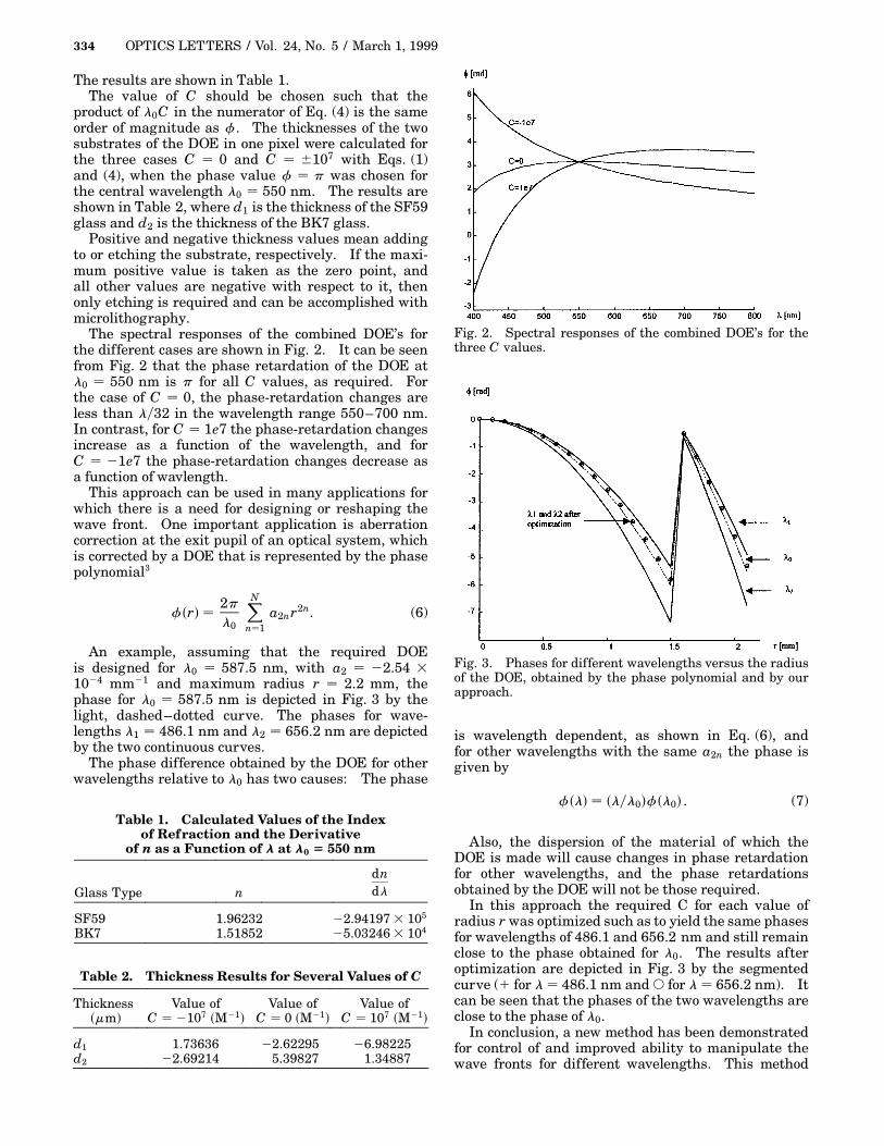
An example, assuming that the required DOEis designed for l0 587.5 nm, with a2 22.54 31024 mm21 and maximum radius r 2.2 mm, thephase for l0 587.5 nm is depicted in Fig. 3 by thelight, dashed–dotted curve. The phases for wave-lengths l1 486.1 nm and l2 656.2 nm are depictedby the two continuous curves.
The phase difference obtained by the DOE for otherwavelengths relative to l0 has two causes: The phase
Table 1. Calculated Values of the Indexof Refraction and the Derivative
of n as a Function of l at l0 5 550 nm
dndlGlass Type n
SF59 1.96232 22.94197 3 105
BK7 1.51852 25.03246 3 104
Table 2. Thickness Results for Several Values of C
Thicknesssmmd
Value ofC 2107 sM21d
Value ofC 0 sM21d
Value ofC 107 sM21d
d1 1.73636 22.62295 26.98225d2 22.69214 5.39827 1.34887
Fig. 2. Spectral responses of the combined DOE’s for thethree C values.
Fig. 3. Phases for different wavelengths versus the radiusof the DOE, obtained by the phase polynomial and by ourapproach.
is wavelength dependent, as shown in Eq. (6), andfor other wavelengths with the same a2n the phase isgiven by
fsld slyl0dfsl0d . (7)
Also, the dispersion of the material of which theDOE is made will cause changes in phase retardationfor other wavelengths, and the phase retardationsobtained by the DOE will not be those required.
In this approach the required C for each value ofradius r was optimized such as to yield the same phasesfor wavelengths of 486.1 and 656.2 nm and still remainclose to the phase obtained for l0. The results afteroptimization are depicted in Fig. 3 by the segmentedcurve (1 for l 486.1 nm and s for l 656.2 nm). Itcan be seen that the phases of the two wavelengths areclose to the phase of l0.
In conclusion, a new method has been demonstratedfor control of and improved ability to manipulate thewave fronts for different wavelengths. This method

March 1, 1999 / Vol. 24, No. 5 / OPTICS LETTERS 335
can be used in many applications. One application,aberration correction, was described.
The authors thank J. Brother for his valuablecomments. S. Noach’s e-mail address is [email protected].
References
1. Y. Arieli, S. Ozeri, N. Eisenberg, and S. Noach, Opt.Lett. 23, 823 (1998).
2. Schott optical glass catalog (Schott Optical Glass,P.O. Box 2480 D-Mainz, Germany, 1980).
3. H. P. Herzig, Micro-Optics Elements, Systems and Appli-cation (Taylor & Francis, London, 1997).