Embed Size (px)
Citation preview
Step 1 Forming the Lid
Select 3 roof pieces. Using masking tape as a clamp glue the three pieces together to form a dome shaped lid.
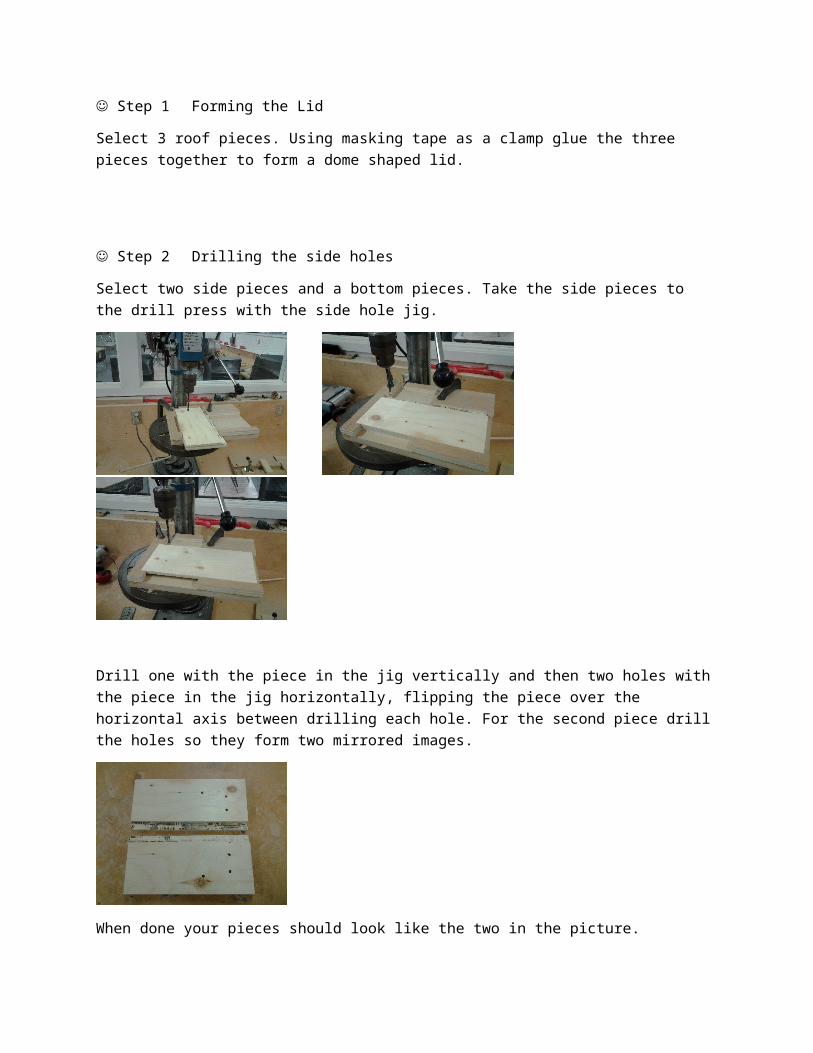
Step 2 Drilling the side holes
Select two side pieces and a bottom pieces. Take the side pieces to the drill press with the side hole jig.
Drill one with the piece in the jig vertically and then two holes with the piece in the jig horizontally, flipping the piece over the horizontal axis between drilling each hole. For the second piece drill the holes so they form two mirrored images.
When done your pieces should look like the two in the picture.
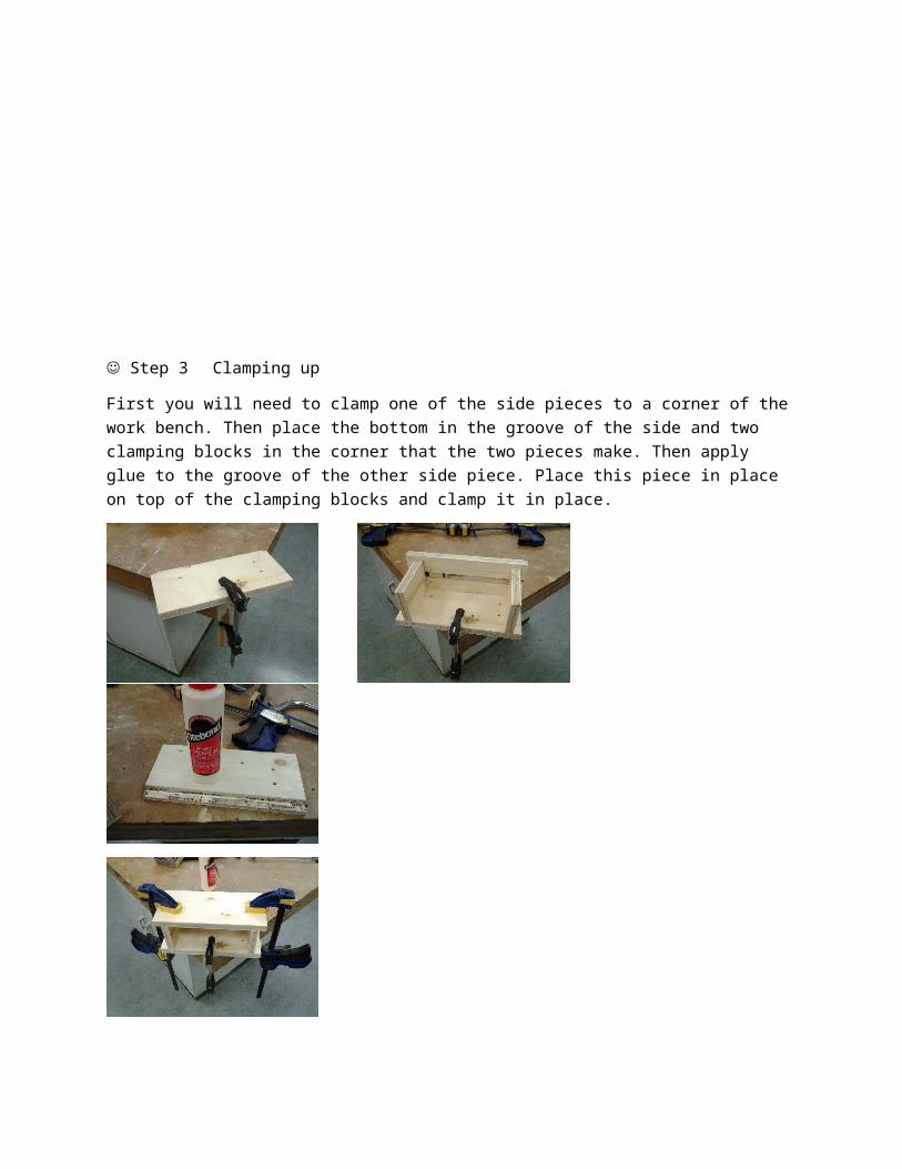
Step 3 Clamping up
First you will need to clamp one of the side pieces to a corner of the work bench. Then place the bottom in the groove of the side and two clamping blocks in the corner that the two pieces make. Then apply glue to the groove of the other side piece. Place this piece in place on top of the clamping blocks and clamp it in place.
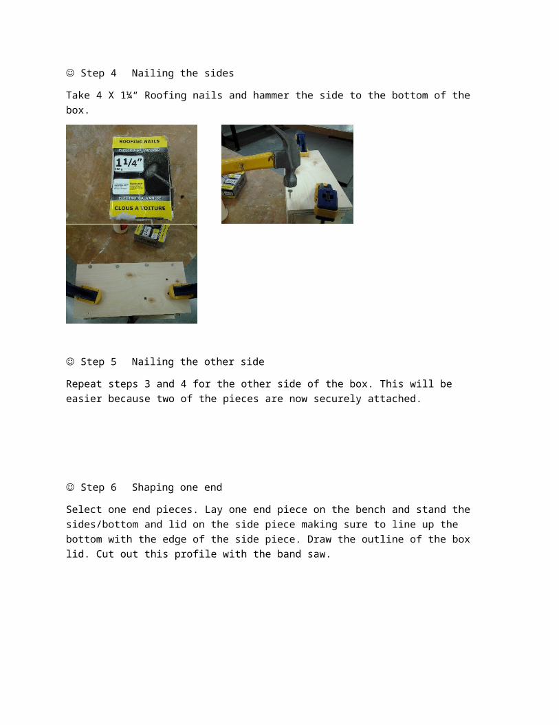
Step 4 Nailing the sides
Take 4 X 1¼“ Roofing nails and hammer the side to the bottom of the box.
Step 5 Nailing the other side
Repeat steps 3 and 4 for the other side of the box. This will be easier because two of the pieces are now securely attached.
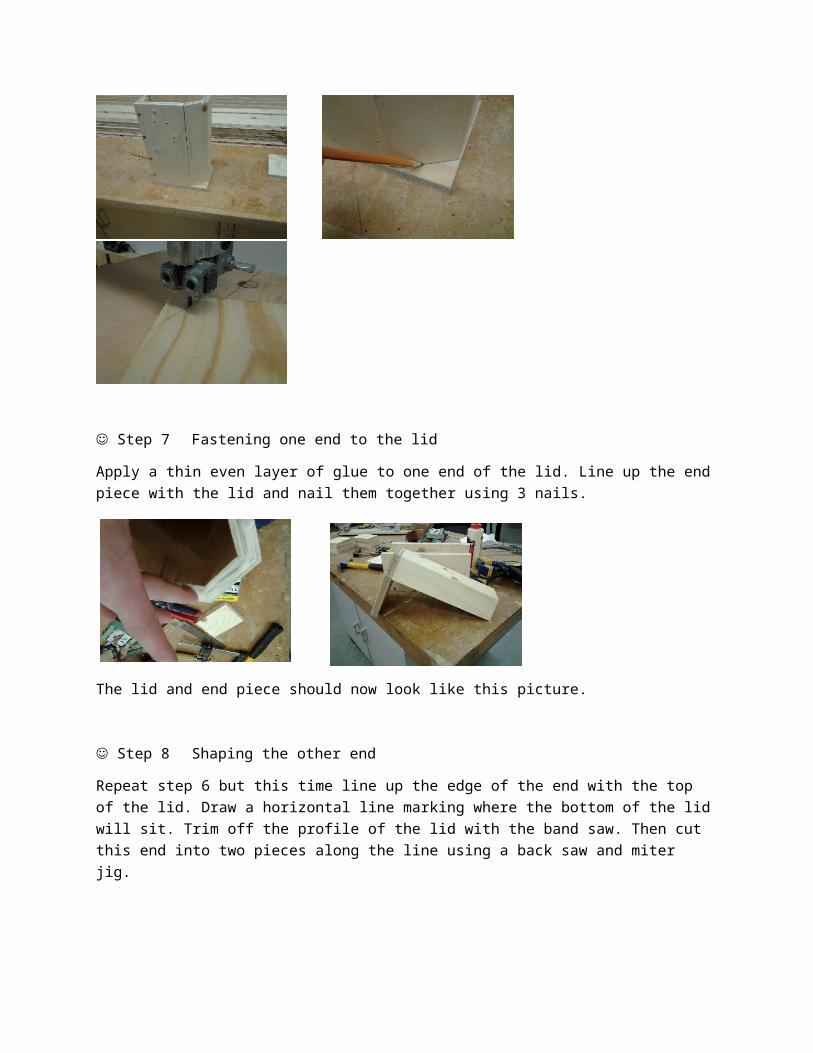
Step 6 Shaping one end
Select one end pieces. Lay one end piece on the bench and stand the sides/bottom and lid on the side piece making sure to line up the bottom with the edge of the side piece. Draw the outline of the box lid. Cut out this profile with the band saw.
Step 7 Fastening one end to the lid
Apply a thin even layer of glue to one end of the lid. Line up the end piece with the lid and nail them together using 3 nails.
The lid and end piece should now look like this picture.
Step 8 Shaping the other end
Repeat step 6 but this time line up the edge of the end with the top of the lid. Draw a horizontal line marking where the bottom of the lid will sit. Trim off the profile of the lid with the band saw. Then cut this end into two pieces along the line using a back saw and miter jig.
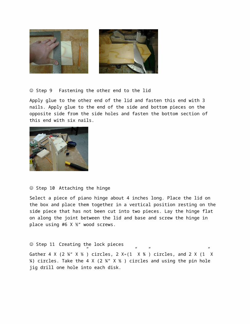
Step 9 Fastening the other end to the lid
Apply glue to the other end of the lid and fasten this end with 3 nails. Apply glue to the end of the side and bottom pieces on the opposite side from the side holes and fasten the bottom section of this end with six nails.
Step 10 Attaching the hinge
Select a piece of piano hinge about 4 inches long. Place the lid on the box and place them together in a vertical position resting on the side piece that has not been cut into two pieces. Lay the hinge flat on along the joint between the lid and base and screw the hinge in place using #6 X ½“ wood screws.
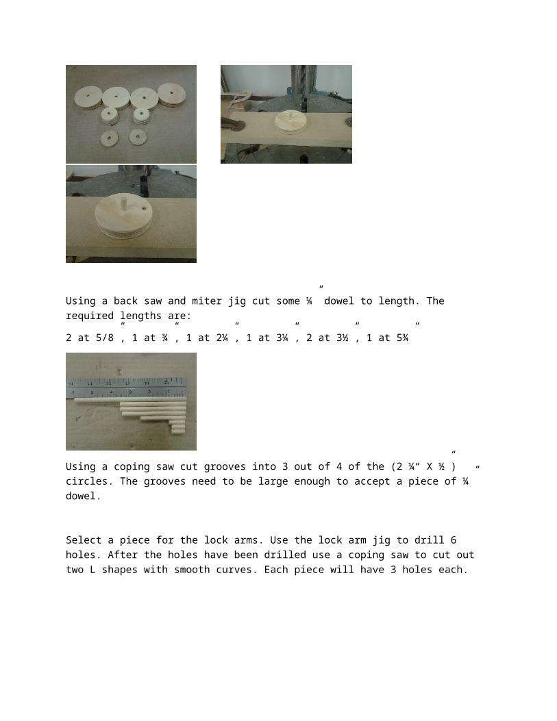
Step 11 Creating the lock pieces
Gather 4 X (2 ¼“ X ½”) circles, 2 X (1” X ¾”) circles, and 2 X (1” X ¼) circles. Take the 4 X (2 ¼“ X ½”) circles and using the pin hole jig drill one hole into each disk.
Using a back saw and miter jig cut some ¼” dowel to length. The required lengths are:
2 at 5/8”, 1 at ¾”, 1 at 2¼”, 1 at 3¼”, 2 at 3½”, 1 at 5¾”
Using a coping saw cut grooves into 3 out of 4 of the (2 ¼“ X ½”) circles. The grooves need to be large enough to accept a piece of ¼” dowel.
Select a piece for the lock arms. Use the lock arm jig to drill 6 holes. After the holes have been drilled use a coping saw to cut out two L shapes with smooth curves. Each piece will have 3 holes each.
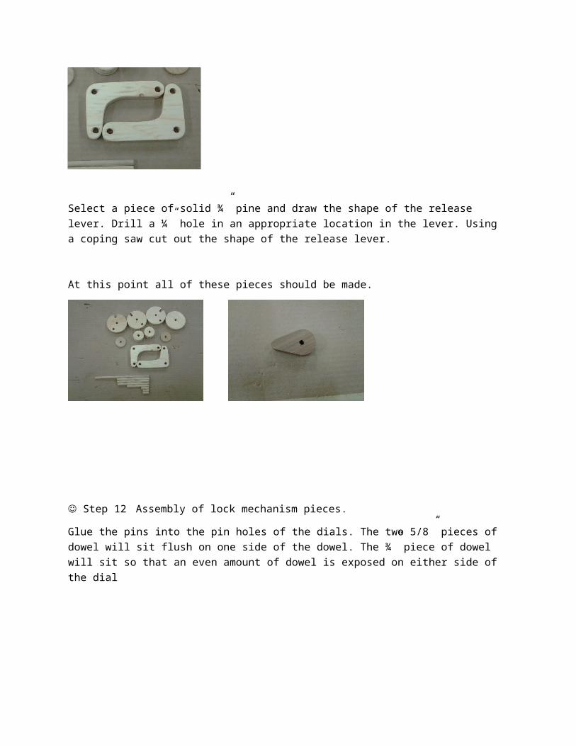
Select a piece of solid ¾” pine and draw the shape of the release lever. Drill a ¼” hole in an appropriate location in the lever. Using a coping saw cut out the shape of the release lever.
At this point all of these pieces should be made.
Step 12 Assembly of lock mechanism pieces.
Glue the pins into the pin holes of the dials. The two 5/8” pieces of dowel will sit flush on one side of the dowel. The ¾” piece of dowel will sit so that an even amount of dowel is exposed on either side of the dial
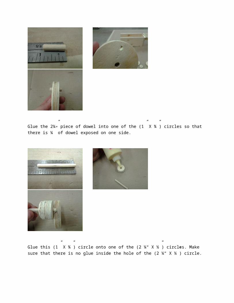
Glue the 2¼” piece of dowel into one of the (1” X ¾”) circles so that there is ¼” of dowel exposed on one side.
Glue this (1” X ¾”) circle onto one of the (2 ¼“ X ½”) circles. Make sure that there is no glue inside the hole of the (2 ¼“ X ½”) circle.
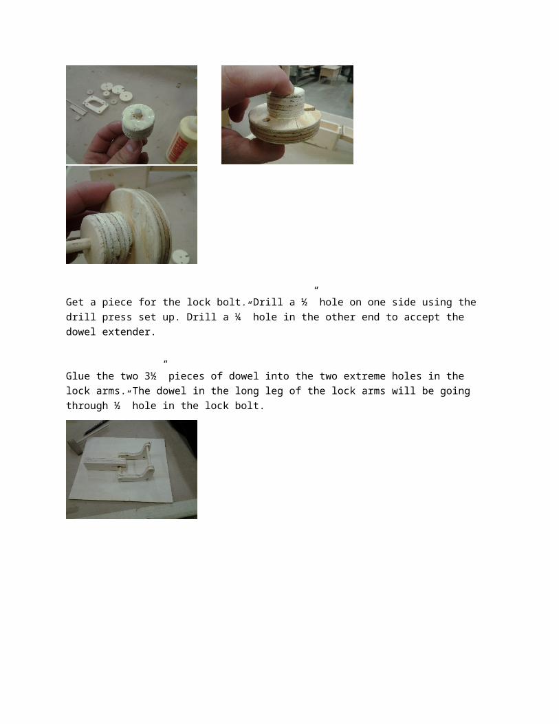
Get a piece for the lock bolt. Drill a ½” hole on one side using the drill press set up. Drill a ¼” hole in the other end to accept the dowel extender.
Glue the two 3½” pieces of dowel into the two extreme holes in the lock arms. The dowel in the long leg of the lock arms will be going through ½” hole in the lock bolt.
Glue the 5¾” piece of dowel so that one end is flush with the side of the release lever.
Glue the 5” piece of dowel into the two bottom most holes in the side of the box.
After the bottom dowel is glued in place the drive dial can be place as is shoe in the picture above.
After the drive dial is in place feed the 3¼” dowel in the opposing hole and sliding the spacers and dials so that they look like the below picture. After all of the dials and spacers are in place, glue the dowel in place by applying a drop of glue to the outside of the casing around the dowel hole.
Line up the lock bolt in the groove along the bottom of the box. The two remaining holes in the lock arms will line up with the two remaining holes in the box sides. Slide the dowel that is attached to the release lever through the all four of these holes. Attach this dowel to the lock arms my applying glue and to both the dowel and the lock arms. Once the glue on one side is dry turn the box over and apply glue to the other lock arm.
Apply glue to the inside of the fourth (2 ¼“ X ½”) circle. Glue this circle to the outside dowel of the drive dial.
Clamp the lock bolt in place and using a ¼” bit drill into the bolt for ½”. Using a dowel center locate where this hole will hit when the lid is closed. Dill an opposing ¼” hole ½” deep. Glue a ¼” piece of 1” long dowel. Into the hole in the lock bolt.
Group Media Project#TeamAwesomeMario AvilaJohn BairdKevin McGregorJames DoverDalia ElramlyLLED 361-296Theresa RogersJune 25, 2014
The project described above encompass the following literacies (non-inclusive)
Literal Visual Oral Language (could be taught in German, French, other) Shop related jargon (eg. Kerf, RPM, joint, adhesive, etc.) Math & Measurement Hand-eye coordination Gestural Technological