Embed Size (px)
Citation preview

with Westinghouse heavy-duty
metal-clad switchgear
WITH TYPE DH DE-ION]; AIR CIRCUIT BREAKERS Horizontal Drawout
150 to 500 MVA Interrupting Capacity
5,000 and 15,000 Volts* • 600 to 2,000 Amperes
Indoor and Outdoor Service
*see note-page 3 www . El
ectric
alPar
tMan
uals
. com

www . El
ectric
alPar
tMan
uals
. com

)
The combination of your experience and ours-yours in operating switchgear and ours in designing and building it-has produced this ideal result . . .
A Practical, Standardized Design of Metal
Clad Switchgear that Meets All General In
dustrial and Electric Utility Requirements.
The Westinghouse Switchgear Division location at East Pittsburgh affords concentration of designing and manufacturing operations with ready accessibility to our High Power Laboratory testing and research facilities.
Standardi:.:ed Metal-Clad Switchgear provides important customer benefits not obtainable in speciallyengineered apparatus. It utilizes available stocks of
index Standardization Brings 1 0 Major Advantages
Indoor Metal-Clad Switchgear
Breaker replacement
Breaker inspection Maintenance of components Standard arrangements-5 * kv
Standard arrangements-7. 5-15 * kv Available arrangements
Outdoor Metal-Clad Switchgear
Construction and operation
Accessories and details
Standard arrangements
Field assembly data
Available arrangements
4-5
6-17
6-7
8-9
10-11
12-13
14-15
16-17
18-25
18-19
20-21
22-23
24
25
standard materials . . . permits planned tooling and master precision fixtures for the fabricating, assembling, wiring and finishing processes . . . employs proved, uniform methods of workmanship. These standard materials, facilities and methods make possible repetitive manufacturing processes that produce a consistently high-quality product at reduced manufacturing time and cost . . . and thus enable us to deliver switchgear faster and at lower installed cost to you.
In short, Westinghouse Metal-Clad Switchgear offers safer and more efficient operation at low cost-throug h Standardized Design that adequately allows for simplified expansion or conversion. That's why . . .
It's Stanclarclizecl for You!
Design Features Common to Indoor and Outdoor Switchgear
Horizontal drawout breakers Stored-energy operating mechanism Fast, positive De-ion® arc interruption Master manufacturing fixtures Positive interlocking devices Complete safety Ventilation, wiring, instrumentation Bonderizing and surface finishes
Application Information
Chart of Standard Units
How to Order
Specifications for Standard Units
Typical Installations
26-37 26-27
28 28-29
30 31
32-33 34-35 36-37
38-40
41-43
44-45
46-52
53
* The Metal-Clad voltage ratings o} 5,000 and 15,000 rolts, as corered in this booklet, are voltage classes. For actual voltage ratings of the power cirmit breakers, see Table A on page 39.
3
www . El
ectric
alPar
tMan
uals
. com

- . --
1. lower planning and ordering costs
The advantages of standardization in Westinghouse Unitized Switchgear first become apparent when you plan for and order new switchgear equipment. Costs normally attached to this phase of procurement are greatly reduced because a simplified ordering procedure eliminates the time and expense usually involved in special engineering, preparing special bills of material and specifications, ordering and receiving special stocks of material.
2. lower manufactured cost
Because standardization permits the use of faster, planned production metho ds, you get in Unitized Switchgear maximum quality at minimum cost. Savings gained by repetitive, tooled manufacturing processes, an adequate stock of standard assemblies and materials, and the elimination of special engineering, are returned to you in the form of a lower price per standard switchgear unit.
3. lower installation cost
Standardization of Unitized Switchgear permits a substantial cut in installation costs too. Its uniform construction enables you to plan conduit and foundation layouts in advance. And, because Westinghouse Switchgear is completely factory assembled, wired and tested to simulate service conditions, you need only to mount the units on their foundation and connect main and control circuits.
4. lower operation and maintenance costs
Standardization creates many features that contribute to lower operation and maintenance costs. Important among these is a design that simplifies operation by providing safe, convenient accessibility to all component parts, more circuits in less space, and disconnects combined physically to breaker elements. Maintenance is simpler because the time required in getting to and servicing the equipment is reduced to a minimum.
S. greater service continuity
Replacement of breakers is only a matter of minutes in Westinghouse Standardized Switchgear. Since breaker units are perfectly interchangeable, new,. units fit without time consumed in matching mounting dimensions or aligning
)
contacts. H orizontal drawout eliminates lowering or lifting. Where multiple \ bus structures are required, interchangeability permits transferring breakers · . _j without interrupting service. www .
Elec
tricalP
artM
anua
ls . c
om

)
6. greater safety
Standardized Westinghouse Switchgear provides unusual safety through interlocking devices and full steel barriers in a completely compartmentalized design. Each compartment is accessible and provides complete isolation against live circuits in adjacent compartments. During operation, inspection or maintenance . . . maximum safety is assured.
7. greater versatility
Jig assembly of the breaker and stationary structure of Metal-Clad Switchgear provides unusual versatility. Units can be rearranged within the same structure or moved from one location to another with almost full salvage value. And because all 600 and 1 200-ampere breakers in the same voltage class are physically interchangeable in stationary structures, conversion to a higher interrupting capacity can be accomplished with minimum expense.
8. longer life
Complete standardization of Unitized Switchgear permits the employment of materials, processes and manufacturing methods that produce a strong, durable switchgear structure. This steel stationary structure provides long-lasting protection against damage to breakers and other vital interior parts. The stationary structure is protected against rust by a Bonderizing treatment and other finishing processes that add years to housing life.
9. shorter manufacturing time
Planned production methods also serve to improve delivery by cutting the time between the placing of your order and final installation of switchgear equipment. Because production is based on standardized drawings and requires only standard stock assemblies and materials, no time is lost in special engineering, special manufacturing or waiting for deliveries from outside suppliers.
10. unit responsibility
Standardized Westinghouse Switchgear assures complete, undivided responsibility through complete control of design and manufacture of all component parts used in its assembly. This co-ordination of design and equipment assures the highest quality and finest performance of the equipment.
5
www . El
ectric
alPar
tMan
uals
. com

The first section deYoted to indoor switchgear contains facts reL:ting to O?eration, standard and available arrangements, and dimensi:->ns. Similar information relating to outdoor switchgear wiil be found on pages 18 through 2 5. Type DH Air Breakers and other fe:::.t:ues common to both indoor and outdoor S\Vitchgear are covereC: on pages 2 S through 3 7.
CONTROL CUT-OFF SWITCH
DOOR LATCH
DOOR STOP
RAILS FOR
BREAKER ELEMENT RELAYS
The fast breaker replacement feature contributes to
the high degree of service continuity obtainable with
Westinghouse Standardized Switchgear. The inter
changeable breakers eliminate time consumed in
; matching mounting dimensions or aligning contacts. Since breakers are drawn out horizontally, no lowering or lifting is necessary. 'Where multiple bus structures are required, the interchangeability feature ot
AMMETER
SWITCH Fig. 1.
FLEX I TEST W A TTHOUR
METER
CONTROL RELAY
AMMETER SWITCH
INDICATING LAMPS
SHUTTER POSITION
SHUTTER
SHUTTER
CAM
MEMBER LEVERING-IN
MECHANISM
TYPE DH BREAKER IN TEST POSITION
is a simple procedure the apparatus permits transferring breakers without interrupting service.
Standardized units have a background of operation experience which eliminates unproved features. Full steel barriers separating compartments, fully insulated busses and auromatic interlocks are features that boost reliability and minimize the possibility of service interruption.
\ I _ _./ www .
Elec
tricalP
artM
anua
ls . c
om

Fig. 3. Push the circuit breaker to test position. stopped at test position by drive-in device. Metal primary disconnects remains closed.
Breaker is shutter for
Fig. 2. Bring up replacement breaker and line up wheels o n track. \'7heels have two rim surfaces-one for the floor, the other, of smaller diameter, for the track which lines up breaker in the stationary structure. i
Jil'lk!Ji�1i\'Dli��4l�����m;���;;��'W�120'fl!����m'ii{f1���������-;g�.:tii�
Fig. 4. Crank to connect. M:ove;nent from test to operating position is accomplished by a few easy turns of the crank. The metal shutter opens automatically as the breaker is advanced (see page 3 3). An interlock prevents crank motion if breaker is in closed position (see Fig. 1 0 1 , page 31).
i I
Fig. 5. Turn on power. Two metal barriers are between operator and breaker when circuit is energized, providing complete safety to operator. Control switch has modernistic design handle (see page 3 5).
7
www . El
ectric
alPar
tMan
uals
. com

Fig. 7. Remove interphase barrier by !. loosening holding b olts and sliding it �, forward. This exposes all arc chutes. One man can handle the barrier.
Fig. 6. Remove breaker. Breaker is pulled straight out.
is convenient Rather than replace breakers when it is desirable to i:heck operation and inspect main contacts, it is only necessary to withdraw breaker and remove interphase
":barrier and arc chutes. Contacts are conveniently
exposed at working height. Breaker can be manually closed, slowly, for check on primary contact operation. The complete inspection takes only a few minutes.
www . El
ectric
alPar
tMan
uals
. com

Fig. 8. Remove arc chutes by removing a f ew accessible bolts. Arc chutes are readily handled.
Fig. 10. CONTACTS OPEN
Fig. 9. Front view of breaker contacts. All three pole units are accessible.
Fig. 11. CONTACTS CLOSED
Breaker contacts are accessible at a convenient working height. Close inspection is not impaired by cramped quarters. No further disassem bly is necessary for inspection and minor maintenance of the contacts.
;_
9
www . El
ectric
alPar
tMan
uals
. com
10
Fig. 13. Current transformers are accessible from rear. View at right shows arrangement of transformers and cable clam ps.
Fig. 12. Remove rear barrier for inspection of transformers and connections. Barrier is removed by unscrewing a fe w bolts.
fo r mai n t e n a n c e
Standardization of Westinghouse Metal-Clad Switchgear provides many features that contribute to lower maintenance costs. Removable, bolt-on covers make components in the various metal-enclosed compartments readily accessible. Inspection and maintenance of a portion of a circuit is easy and safe because that
circuit can be completely de-energized rrnd isolated from other circuits of the switchgear assembly. The disconnecting contacts are combined physically with the removable breaker element. Insubted circuits in compartmentalized structures provide more circuits in less space with greater safety and lower operating cost.
www . El
ectric
alPar
tMan
uals
. com

Fig. 14. Remove barriers of main bus compartment. Busses are also accessible from breaker comparrment.
Fig. 16. Busses easily extended when adding units. Bus ends,
) insulation, support and cover are removed. An insulated support completes bus insulation between units,
Fig. 1 ; , Potential transformer in auxiliary compartment. Drawout arrangement automatically disconnects and grounds transformer when access to BAL fuses is necessary.
Fig. 17. Bus taps enclosed . . . Moldarta ® compound box easily installed and filled with insulating compound.
11
www . El
ectric
alPar
tMan
uals
. com

j, __ -
�:.INDOOR SWITCHGEAR. 5 KV· ·� standard arrangements ' . .
... �-r •
CONTROL PANEL----------._
-SOLID METAL BARRIER -----OUTLINE
--; CONDUCTOR CONTROL CUTOFF SWITCH--------
VENTILATION DUCT ----------� REMOVABLE BARRIER
HINGED INSTRUMENT PANEL ----------1
CURRENT TRANS FORMER ----------+------l----�� SHUTTER ---------------- t--------��B�R�E�A�K�E�R_j1
GROUND BUS ---------------------------�--------����� SECONDARY CONTACTS -----------+--..,----T'----'-f'l'l: I . I 11111 1¢ � t � TERMINAL BLOCK I 11111 t ! i!
I uU: t.•· •. • 'ti ,..... n n )L �'' I I el1t1 1 r-----,-J LJc;d' >G - -
fig. 18
REAR
ii J� I
steel barriers confine any possible disturbance. Ys-inch steel forms compartments for busses, instrument transformers, etc. Isolation of compartments is aided by use of Micarta ® and other insulating materials.
individual access to all compartments is provided by removable barriers at points ;indicated above. Operator is not exposed to live circuits in adjacent compartments.
outline dimensions
90�
24"MINIMUM AISLE
SPACE AT REAR
SIDE 66 1--74---11 Fig. 19. Outline dimensions of Metal-Clad Units for 50-DH-150 and 50-DH-250 Switchgear.
TYPE DIMENSIONS APPROX. WEIGHT OF AMPS Dead *Impact
UNIT A B c D E F Weight Weight -- -- --- --- --- ---
50-DH-150 1 200 26 36 17 111% 1()2,.{6 101%6 3000 3600 50-DH-250 --- ---- -- --- --- --- --- ---
50-DH-150 50-DH-250 . 2000 36 43 23 161;{6 15;{6 151%; 3400 4000
All 75 and 150 1200 See Figure 28, Page 15
4000 5000 DH Ratings 2000 4200 5300
NOTE: Actual weight will vary in proportion to amount and type of auxiliary equipment in the units.
* Total includes dead weight.
NOTE 1-%" x 1)411 slotted holes for %11 bolts or plug welding. Plug welding preferred.
NOTE 2-Maximum space for secondary conduits-1:Yz" maximum size-311 maximum above floor.
NOTE 3-Maximum space for main conduits.
NOTE 4-Location for purchaser's ground connection. In groups involving six units or less, this connection is made in the second unit from the left end. In larger groups, ground connections are made in the second unit from each end.
For recommended mounting of switchgear units, see page 15. www . El
ectric
alPar
tMan
uals
. com

FRONT
FRONT FRONT
BREAKER
Fig. 20. Bus sectionalizing arrangement.
FRONT REAR
Fig. 21. Auxiliary unit housing two sets of drawout disconnecting-type potential transformers.
Fig. 22. End compartment for incoming lines, connected directly to bus.
maximum number of panel-mounted instruments and relays
TYPE KA-25 INSTRUMENTS
FLEXITEST WATTHOUR METERS OR RELAYS, OR TYPE KA-25 INSTRUMENTS
FLEXITEST WATTHO UR METERS OR RELAYS
FLEXITEST RELAYS
26 __ .,j.,., .. ,__ __ 26 36 --··1
0
ODD c::::l co
qp
0
TYPICAL UNITIZED PANEL
ODD DODD liJQ gggg DO u ODD u oOo oOo DODD DODO
= = co oc
qp [jjl
DO DOD DO 0 DOD DO ODD MAXIMUM MAXIMUM
PANEL EQUIPMENT PAN EL EQUIPMENT
0
90� 8
13
www . El
ectric
alPar
tMan
uals
. com

SOLID METAL B ARRIER ·------- OUTLINE
CONDUCTOR VENTILATION DUCT REMOVABLE BARRIER
CROSS WIRING D UCT--��� ��� �� ��--�---------��r-
�F�R�O�N�T��
----------�==��� ·---------R�E�A�R--·.
CONT ROL PANEL I ,..=�
HINGED INSTRUMENT PANEL � CONTROL CUTOFF SWITCH -�-------- --�-�--��-�+___/ '--
STEEL I SOL AT I NG BARRIER --���--�--------------1-----------------.. CURRENT TR A NSFORMER--------�----���--�-�--+-----------1--------------��--�
SHUTTER ----�--------�-------�--------------��------��-----------,\ BRE AKER F
·;·� 11-·- ;J _rlf IJ 'ir CABLE CLAMP OR COMPOUND BOX -------------+------1-------�-::::·-"1� �----�'I u
•<,· T-
GROUND BUS---------------------1-----���������.
' I TERMINAL BLOC K-- -- --------------------------- -���
�
SECONDARY CONTACTS -------------------�� �������r�lr-�� �--------- �
.(1 � I .... � ' ' " ' �
steel barriers confine any possible disturbance. Ys-inch steel forms compartments for busses, instrument transformers, etc. Isolation of compartments i s aided by use of Micarta and other insulating materials.
FRONT r. REAR
[
� BREAKER I�
,,� FRONT
Fig. 2 5. Bus sectionalizing arrangement.
U tljl ,,,, r: t ,, till �r � �h uw
� I .�J
Fig. 24 /
individual access to all compartments is provided by removable steel barriers at points indicated above. Operator is not exposed to live circuits in adjacent compartments.
FRONT �EAR
GROUND
Fig. 26. Auxiliary unit housing two sets of drawout disconnecting type potential transformers.
REAR FRONT ------�
tj::�;� 1...-..;,r:__.J ____ -- _____ j FRONT VIEW
Fig. 27. End compartment (for incoming lines) connected directly to bus.
_/
www . El
ectric
alPar
tMan
uals
. com
swiTCHGEAR "l_ , _ -5--.1511 d arrangements •
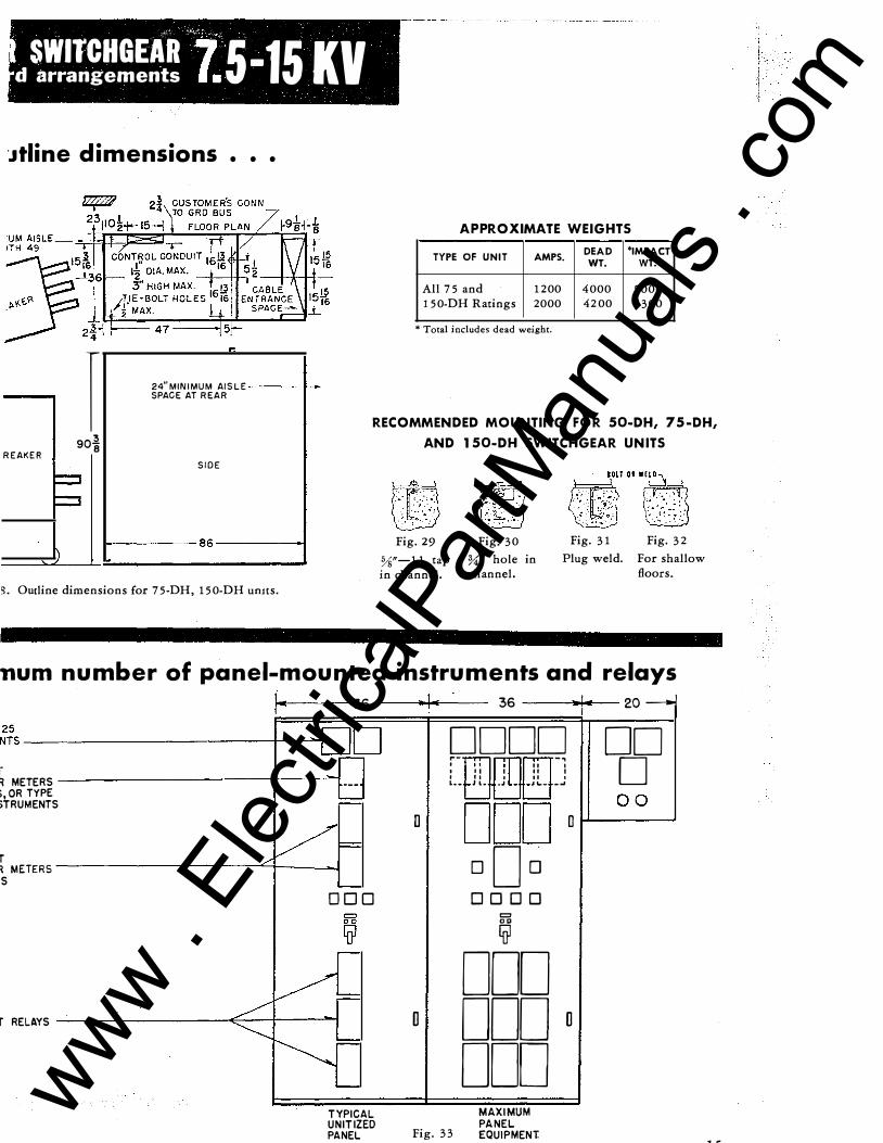
'Jtline dimensions • • •
..
24"MINIMUM AISLE SPACE AT REAR
APPROXIMATE WEIGHTS
TYPE OF UNIT AMPS. DEAD *IMPACT
WT. WT.
All 75 and 1 200 4000 5000 150-DH Ratings 2000 4200 5300
* Total includes dead weight .
I 90� 8
RECOMMENDED MOUNTING FOR 50-DH, 75-DH,
AND 150-DH SWITCHGEAR UNITS REAKER
SIDE
� �
1\ 86
S. Outline dimensions for 75-DH, 150-DH umts.
Fig. 29 Fig. 30
%"- 1 1 tap %;" hole in in channel. channel.
Fig. 3 1 Fig. 3 2
Plug weld. For shallow floors.
num number of panel-mounted instruments and relays
1· 36 --------- 36 ___ , ....... !-- 20 --j ��S --------------------------�r-��t==Jc=J
r-I R METERS --------------t------""'i ·->,OR TYPE >TRUMENTS
T /�= R METERS --------- ---q.----J 'S
T RELAYS
L..--
000
TYPICAL UNITIZED PANEL
D
D
DODD DD r- � a. II -� D I I I I II I I I l t II 1 L •• J L. ..1 .. .. JL. .. -�
ODD 0 1-L--0----�0
oOo DODO
=
� DOD DODD DOD Fig. 33
MAXIMUM PANEL EQUIPMENT. 1 c
! -www .
Elec
tricalP
artM
anua
ls . c
om

FRONT REAR
Fig. 46. Double bus-double breaker arrangement.
Fig. 47. Potential transformer -drawout type-in superstrucrure compartment.
Fig. 48. Lightning arresters connected to line.
Fig. 49. 3000-ampere busses-interlaced paralleled bars in supersttuc
, ture increase depth of cell 12 inches.
FRONT REAR
Fig. 52. Auxiliary unit for operating transformer and disconnecting fuses with disconnecting potential transformer, bus connected.
F'RONT
BREAKER
Fig. 55. Instrument panel opposite breaker side adds 16 inches to
FRONT REAR
Fig. 50. Disconnecting switch unit with drawout potential transformer.
FOR METERING
FOR RELAYING
Fig. 53. Transfer bus with discon· necting switch.
Fig. 56. Auxiliary unit for generator excitation control.
REAR REAR
Fig. 51. Breaker unit requiring potheads for two or three parallel 3-conductor cables increases depth of standard unit 12 inches.
FRONT REAR
Fig. 54. Auxiliary unit for surge protective equipment.
FRONT
Fig. 57. Auxiliary unit for syncluo-nous motor field control. 1 7
www . El
ectric
alPar
tMan
uals
. com

'
I A
i :\ I ! ..
) t. ' ., )
Rigid, self-supporting, jig-welded unit construction.
�-. Weatherproof, corrosion-resistant base construction.
, , Removable ventilating screens at top and bottom of both sides of unit.
Adjustable breaker transport truck in stOrage location (with operating transformer of 1 0 kva maximum capacity).
Latching mechanism.
,, . Heater assembly (on breaker side and panel side).
Weather-tight, removable roof assembly.
Light and convenience outlet.
Door to disconnecting Type BAL fuse assembly.
AB Breaker and interlock assembly to fuse door (9) to isolate secondary load of operating transformer before breaking or making primary fuse connections.
Operating transformer.
Shutter position indicator.
, . Door stop and latching assembly. ' !: Rectox rectifier for closing breaker.
Design planning has resulted in providing a distinctive Westinghouse family of outdoor metal-clad units for the complete range of air circuit breaker ratings with their associ a t e d auxili a r y units.
Fig. 59. Panel side of feeder breaker unit. www .
Elec
tricalP
artM
anua
ls . c
om

·outdoor unit-constructed weatherproof assemblies
Fig. 60. Breaker unit stationary structure.
Unit construction of Westinghouse outdoor swirchgear provides versatility to meet the needs of expanding electrical systems.Compartmentation is planned to provide maximum use of space, safe operating arrangements, and accessibility for inspection and maintenance. Removable bolted-on covers give access to high-voltage circuits.
Fig. 6 1. Auxiliary unit stationary structure.
adiustable transport truck facilitates breaker handling
Fig. 62. Aligning adjustable transport truck with ll.oor rails of stationary structure.
Fig. 65. Crank breaker element to operating position in stationary structure.
Fig. 63. Latch transport truck to stationary structure. Combination latch releases breaker unit.
Fig. 6 6. Close and latch stationary structure door-breaker side.
Fig. 64. Place breaker in disconnect position.
Fig. 67. Close breaker element by control switch on hinged instrument and relay panel-panel side.
19
www . El
ectric
alPar
tMan
uals
. com

acce�sories fo r outdoor metal-dad switchgear
Fig. 71. Adjustable transport truck with combination latching device for breaker and stationary structure.
Fig. 72. Details and accessories for Outdoor Metal-Clad Switchgear: (1) Ventilator screen-top; (2) Ventilator screen-bottom; (3) Light and convenience outlet; (4) 600-volt P & N terminal block; (5) heater assembly; (6) test jumper.
all-weather undersurface coating provides lasting protection against rust and corrosion
All - weather undersurface coating for outdoor switchgear is heavy, rubberized, protective sealing material. Spray-applied to outdoor switchgear undersurfaces, it provides a thick airtight seal against corrosive elements. Note thick, rugged appearance of coating 1n close-up view in inset.
Fig. 73 21
www . El
ectric
alPar
tMan
uals
. com

;: < - • 1 < �
-;, OUT' DOOR METAL-CLAD SWITCHGEAR
' ..
dimensional data
sl x 6 COTOUTS FOR SEC. CABLE CONN.
CUTOUT FOR MAIN CABLE CONN
.
�------------------6------------------� (65 X 34 HINGED PANEL- 2000 A. 5 K V \_65 X 24 HINGED PANEL-1200 A.
7.5-79 X 34 HINGED PANEL-600·1200-15 KV 2000A.
:.. 74, B�< pl•n dimondon• "'' bmko' uniu. � Fig.)5. Typical air circuit breaker unit. t
c
POWER TRANSFORMER BUS OR BUS SECTIONALIZING BUS �HEN REQUIRED
. tol4 5
KV,
SHUTTER 12�� GROUND BUS 7
.5
K
�5 I I I
����::::::::::::::sc..:;.·_j::::,.·u I J ---------------------- G__j SECTION SIDE VIEW
..
i BREAKER I REMOVAL
TYPE DH AIR CIRCUIT BREAKER STATIONARY STRUCTURES
UNIT DIMENSIONS ESTIMATED APPROX. UNIT CURRENT
RATED AND RATING KV TYPE AMPERES A 8 c D E F
G Dead Impact Min. Weight Weight* -- ---
' 50-DH-150 600- 1200 4. 16 28 90 90 8% 107{ 10 42 3900 4500 50-DH-150 2,000 4. 16 38 90 90 13% 157{ 10 49 4300 4900
50-DH-250 1,200 4. 16 28 90 90 8% 107{ 10 42 3900 4500 50-DH-250 2,000 4. 16 38 90 90 13% 157{ 10 49 4300 4900
75-DH-250 1200-2000 7.2 38 102 104 13% 157{ 12l{s 49 5000 6000 75-DH-500 1 200-2000 7.2 38 102 104 13% 157{ 12\1s 49 5200 6300
150-DH-150 600- 1200 13.8 38 102 104 13% 157{ 12\1s 49 5000 6000 150-DH�250 1200-2000 13.8 38 102 104 13% 157{ 12\1s 49 7200 6300 150-DH-soo 1200-2000 13.8 38 102 104 13% 157{ 12\16 49 5200 6300
*Total includes dead weight. Actual weight will vary in proportion to amount and type of auxiliary equipment in the unit.
AUXILIARY UNIT STATIONARY STRUCTURES
Auxiliary ... ........ 4.16 30 90 90 · · · · · . .... . ... . I 30 I 3800 . ... .. .
Auxiliary .. ... -...... 7. 2 38 102 104 · · · · · . .. .. . .... 38 4200 · · · · · ·
Auxiliary .. . . ....... 13.8 38 102 . 104 . .... . .. . . . . .. ... I 38 4200 I . . . ... '�, .. · .. <·< www .
Elec
tricalP
artM
anua
ls . c
om

.
dimensional data '�-------34 --------� r-�'------------------� E]EJE]
HING SIDE �
TOG. EJ� = �-�]
CB·3 =
�8 AMO sw.L_.J
ffil8 I c�:)N sG sw.
[][] EJEJ GRD
Typical 5-kv panel.
-
65
Fig. 76. Layouts showing number of panel mounted instruments and relays for typical outdoor switchgear.
rc A
79
:ar:r�G El ro: -
@] -
DAM • . sw. � ..
= D DCONT fVJsw.
BBEJ
L� ...
� L---------------------�
Typical 7.5-15-kv panel.
��L--------------------------•�, 1 ,hr--------------9----------------�
5 KV AUXILIARY UNITS BASE PLAN VIEW
Fig. 77. Base plan dimensions for auxiliary units.
REASONABLY FLAT SURFACE FOR WALKING
FRONT REAR
TRUE AND LEVEL
FOUNDATION
Fig. 79
�----------------6--------------�
Fig. 78. Typical auxiliary unit.
- . . • • ·
.'. � PIT TYPE
• . . . • . . . :: : CONST .
.. "'-·:. ·� :.'.y··.·.·
Fig. 80
\SOLID CONCRETE PAD
Fig. 81
23
www . El
ectric
alPar
tMan
uals
. com

field assembly data
ROOF TRIM
M ' +
REAR
--�----SECTION C-C
SECTION A-A
------0----------;: -----------0-------- .... :
I I I I I I
I I I I
I I I I 1.-----o----------o-----------�-------+1 I 1 I I I I I I I I I I
I I I I I If
LEFT HAND 51 DE
REMOVABLE LIFTING LUGS
Fig. 82
1 ASSEMBLY O F GROUPS • • •
(a) Line up adjacent groups-install front, rear, and base tie bolts-draw bolts tight to get continuous close contact of all adjacent sheets.
(b) Install roof seam covers-L.H. removable side sheets and R.H. finishing trims.
2 ASSEMBLY O F NEW GROUPS TO G ROUP ALREADY INSTALLED • • •
( a-1) If new group is added to L.H. end of old group,
PANEL SIDE
lfc
Q
(!-----------II' II II II II
I ! _________ J I• 0 I I I I I I I I
II
. j; ------- -;;---I I I I I I I I :� . 'T
RIGHT HAND SIDE
remove L.H. side sheet from old group-place new group in position and make assembly per 1 (a & b).
(b- 1) Assemble side sheet & roof seam cover from (a-1) on L.H. side of new group.
( c- 1) If new group is added to R.H. end of old group, remove R.H. finishing strips from old group. Place new group in position and make assembly per 1 (a & b).
(d-1) Assemble finishing strips and roof seam cover from ( c-1) on R.H. side of new group. www .
Elec
tricalP
artM
anua
ls . c
om

available outdoor metal-clad switchgear arrangements
-+--1 I
I PANEL l�r:..---1 I - -
-fl 1---��\ SIDE
- - .
[ �t rt L. r-] �-
KNIFE
sw.
R.;_ IN ST.
VNEL
J.IEATER
�, l
[ -rr-CROSS I f WIRE
I I I CONT. I PANEL
I 11 I
:�;D � 5=�: ·v �
·�11��11 II !! II I I I I
!I f
-
REC�� ff1� i �.J --1 I' AIR CIR.
BKR .I I VSHUTTER
1\ : II "
HEATER
R.H.P.V� c=
1) t I
l F-� !� BKR. F----- LJ n I' .I I . . I TRAVEL FROM
OPER. TO ]; TEST POS. II � BKR. SIDE-----""
( •1 l
- l --1-- -- m t"""-� AIR CIR. il uc BKR. � SHUTTER --"
/' I r--�----.,... ,.---r / �
HEATER I I � k R.H.Pg c: 111 I
\
-- � CROSS WIRE-
CONT. I r·1 �J PANEL:
I I
. l"l I I ' tf.J
KNIFE
sw.
l v . C.
IN ST.
PAN� i HE� i I
Fig. 83. Double bus-double breaker arrangement.
PANEL SIDE
Fig. 84. Breaker unit with transfer bus in superstructure.
LT'N'G ARR. /
Fig. 85. Breaker unit with lightning arresters connected to line.
LAMP a PLUG IN RECEP.
Fig. 86. Breaker unit with two threeconductor potheads.
�
www . El
ectric
alPar
tMan
uals
. com
t . '.! ) , .. )
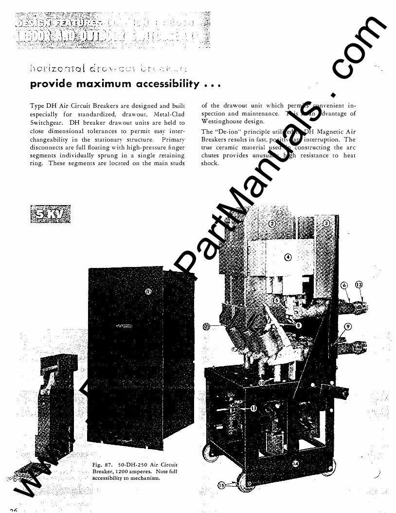
provide maximum accessibility
Type DH Air Circuit Breakers are designed and built especially for standardized. drawour, Metal-Clad Switchgear. DH breaker drawout units are held to close dimensional tolerances ro permit easy interchangeability in the stationary structure. Primary disconnects are full floating with high-pressure finger segments individually sprung in a single retaining ring. These segments are located on the main studs
Fig. 87. 50-DH-2 50 Air Circuit
Breaker, 1200 amperes. Note full accessibility to mechanism.
• • •
of the drawout unit which permits conYenient inspection and maintenance. This is an adYantage of Westinghouse design.
The "De-ion" principle utilized in DH Magnetic Air Breakers results in fast, positiYe arc interruption. The true ceramic material used in constructing the arc chutes provides unusually high resistance to heat shock.
) www . El
ectric
alPar
tMan
uals
. com

)
Interpolc barrier assembly.
Arc chute.
Magnet coils.
I ron pole pieces.
Tungsten alloy secondary breaker contaa:s.
Micarta bushings.
Arc horn connector.
S ilver main breaker contacts.
· Roller for shutter.
. ' ; '
Micana operating rods.
Socket for hand-closing lever .
Secondary contacts.
Primary disconnect.
1 t, , All-welded steel frame construction.
1 5. Two-surface wheels for mobility inside and outside structure.
Fig. 88. 150-DH-2 50 Air Circuit Breaker, 1 200 amperes .
• Fig. 8 9 . Positive contact is obtained on primary disconnects by individual flat springs and heavily silvered, self-aligning, finger-like segments. Segments on breaker are easy to in�pect.
27 www . El
ectric
alPar
tMan
uals
. com

2R
. !
permits manual closing
Operating position.
Manual closing is ideal for primary sen-ice breakers where operation is infrequent and electric closing power is not available.
The Westinghouse spring-operated mechanism for hand-closing type DH breakers makes manual operation safe. Actuated by a pushbutton, it closes the breaker with sufficient speed and force to overcome magnetic effects of short-circuit currents. The breaker can be closed and tripped with the housing door closed and the operator has a visual indication of the breaker position.
Control post down. Control post up.
Fig. 90.
fast� positive De-ion arc interruption
,------ INSULATION ----" I' PLATES
Fig. 91. Arc chute and blowout coil.
The De-ion principle of circuit interruption is an exclusive Westinghouse development.
The action of the breaker in interrupting the arc is illustrated at the left. When the arcing contacts separate, an arc is drawn between them without the blowout coil carrying current. The arc rises rapidly under the influence of the magnetic field created by the iron of the blowout magnet. This causes the arc to impringe on the arcing horns, thus inserting the blowout coil in series with the arc.
When the current starts to flow in the blowout coil, the arc is driven rapidly into the slots in the refractory plates by the magnetic field. The staggering of the slots causes the arc to lengthen as it progresses up t�e chute. This exposes a large part of the arc to the relatively cool surfaces of the plates and to the deionizing effect of the blowout magnet field. Arc ) extinction is rapid, due to elongation, cooling and de-ionization. www .
Elec
tricalP
artM
anua
ls . c
om

)
' . i ' l ;: ,_ '
non-hygroscopic • • •
Fig. 93. Sub-assemblies of De-ion arc chute.
highly resistant to heat shock
The arc chutes in DH breakers are so constructed
that the arc is exposed only to ceramic material.
This ceramic material, containing a high per
centage of Zircon, has the highest melting point
of any known material and great resistance to
heat shock. Its dielectric and moisture absorp
tion properties compare favorably with high
grade porcelain.
Fig. 92. Arc chutes for DH De-ion air breakers.
Fig. 94. Main and auxiliary contacts.
29
www . El
ectric
alPar
tMan
uals
. com

30
,.- .. I i, ' .:; I
i ·- . , ; i: ( assure interchangeability of breakers
A system of rigid double checking during the assembly of 'W'estinghouse Metal-Clad Switchgear assures you of removable elements that fit into any stationary structure of like rating.
This perfect alignment is accomplished: first, by fining all removable elements to a master stationary structure in the assembly section; second, by marching all stationary structures to a master, precision-built, removable element in assembly operations. The result is positive alignment of rails and wheels; main, auxiliary and ground contacts; shutter and main levering-in
device. It eliminates the necessity for fitting on the job . . . provides simple interchangeability of breakers when the switchgear is in service.
iig welding Jig welding assures interchangeability o f standard units. Groups of units may be disassembled, rearranged and new groups added with no additional expense incurred in matching up mounting dimensions. Outline and mounting dimensions are held to close tolerances.
-Fig. 95. Every removable
element must fit exaccly
into a master switchgear
stationary structure.
Fig. 97- Rigid, upright welding fixtures assure uniform, plumb and square stationary structures.
Fig. 96. Every stationary structure is checked for alignment with a master removable element.
Fig. 98. Assembly jig fixture assures accurate location of breaker rails to main contacts, secondary contacts, ground contact, stops and levering-in mechanism for interchangeable breaker units.
. .
www . El
ectric
alPar
tMan
uals
. com

www . El
ectric
alPar
tMan
uals
. com

__ ...... l
The \\? estinghouse standardized design makes full use
of the interlocking devices developed and field
tested in all types of Metal-Clad installations. All
interlocks are simple. A minimum of working parts
assures positive trouble-free operation.
All these safety features are standard equipment 1n
\\"1 estinghouse Metal-Clad Switchgear.
Fig. 99. Positive crank motion brings breaker from test to operating position. Since breaker motion is horizontal, crank is turned quickly and easily.
I ' I I
BR�AKER: � CONTACTS OPEN� I I I
assure greater safety
Fig. 100. Trip lever opens breaker.
Fig. 101. Breaker must be open before it can be cranked. If breaker is closed, the trip-free linkage prevents engagement of crank linkage. When breaker is being cranked, or between test and operating positions, shear pin action with solenoid linkage prevents closing the breaker. Operation
is positive.
-==:tP �RE� �.EVER ___.-., ._ l3RcAKER CC.OSEDl
COUPc,NG DISENGAGED
[: BREAKER CONTACTS OPEN
31 www . El
ectric
alPar
tMan
uals
. com

www . El
ectric
alPar
tMan
uals
. com

32
.·) ���, ·.·' ','\ ·--,�·\. :}
� I .
• • • safer testing
r I
I I I I I I I I I
j?,;:JT��f:1-���f"�t��1!f��J0l;_·�.-f;: BREAKER--J f::C I BLADE ;
f ,:,, ,,: Q?! ,�PI ti!tjJd ----------,
BREAKER
I I I I I I I BREAKER
I I I I I I I I I I
BREAKER
I I I I I I I I I I I
I I I I I I L- ------ ___ J L __________ J
Fig. 103. Breaker in "test" position
• . • by engagement of secondary con
tacts, :breaker can be tested. No
jumpers are needed. Manually
operated, extendable secondary con
tact assembly is mounted on the
breaker. This assembly is normally
keyed in the operating position.
L ___________ J
POSITION (I)
PUSH FROM
\ \ \
(I) TO (2) TO CONNECT SECONDARY CONTACTS
(I (2)
Fig. 102. Ground bus connects to all breakers and cells.
This ground bus has at least 2 5 percent the capacity
of the largest bus. It makes positive contact with all
breakers through blade and jaws illustrated at the left.
The breaker frame is effectively grounded before the
primary contacts engage.
POSITION (2)
SECONDARY CONTACTS MOVE FROM (I) TO (2)
�- . -
www . El
ectric
alPar
tMan
uals
. com

www . El
ectric
alPar
tMan
uals
. com

Fig. 105. Shutter still closed-breaker
in test position, with cam about to raise
shutter.
of live parts
A Ys-inch thick metal shutter, closed by gravity,
positively prevents accidental entry to live stationary
contacts. The shutter drops automatically when the
breaker is removed. Shutter is closed in test position
and is raised automatically as the breaker advances to
operating position. The shutter is a simple mechan
ical device requiring no maintenance.
How shutter works
Before the breaker is removed, shutter supporting
frame rests on breaker frame. As breaker is with
drawn, shutter is closed. When breaker is advanced
from test to operating position, rollers passing along
shutter cams raise the shutter to clear the contacts.
Fig. 104. Shutter closed-live stationary contacts in the breaker cell are covered.
Fig. 106. Shutter open-stationary con
tacts cleared for entry of breaker con
tacts.
Fig. 107. Moldarta or porcelain insulators enclose primary disconnects
· and isolate them from each other.
33 www . El
ectric
alPar
tMan
uals
. com

www . El
ectric
alPar
tMan
uals
. com

' �' ')}
adequate ventilation ... insulation • . • standardized wirih�
Fig. 108. Close-fitting .Micarta bus supports prevent gas
migration between compartments . . . another aid in localizing any possible disturbances. Busses are completely insulated.
Fig. 110. Standardized wiring practice is illustrated in typical panel wiring. Form fitting hinges, loop-molded
wire cleats, molded terminal blocks and rubber-lined wire cable clamp devices permit simplified, quality wiring procedures .
Fig. 109. Busses are completely insulated with compound
filled Moldarta boxes at joints, preformed Mica.rta tubes on straight portions and varnished cambric insulating tape at
bends. Busses have half .rounded edges to eliminate corner
voltage stress. Contact surfaces are silvered and tightly
bolted.
r ......... . I ;:::_,',�-�
__ ...t.._�'r�..::. '..: ""' ��'�<.-k'l..-.._,---���::::. I ,'r'...._,--..,*":::_ I I' '""---""'�r..u.-� I I "K y-.....,.·. --4 I I I ''+----- 1 I I I I I I I I I I I I I I 1 : I I I I
I I I I I I I ��'--------��----------� I I I I I I I I I I I I : I I
OUTDOOR
SCREENED VENT ---+ ---i':
EXPANSION CHAMBER
Fig. 111. Vent discharges arc gas to outside of switchgear
unit.
. .
www . El
ectric
alPar
tMan
uals
. com

www . El
ectric
alPar
tMan
uals
. com
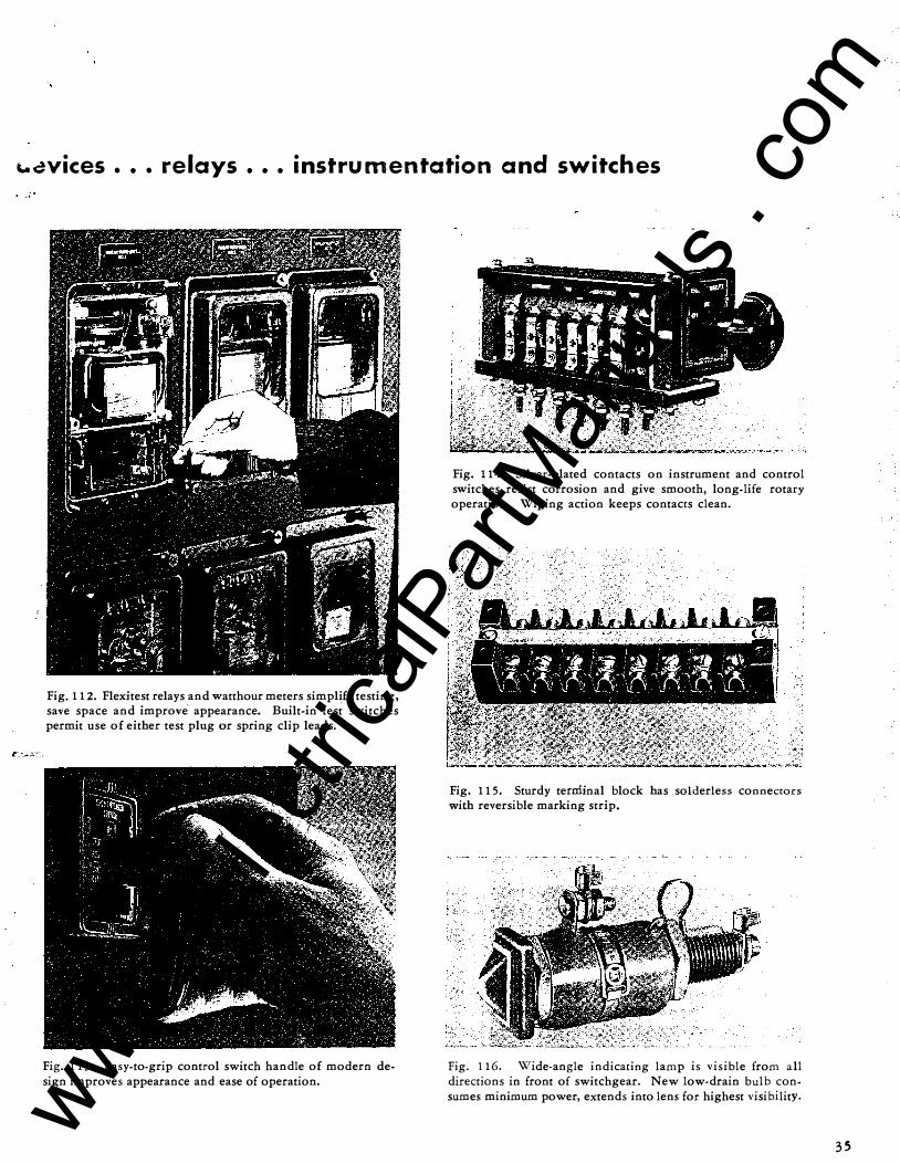
... �vices . • . relays • • • instrumentation and switches
Fig. 112. Flexitest relays and watthour meters simplify testing, save space and improve appearance. Built-in test switches permit use of either test plug or spring clip leads.
Fig. 1 13. Easy-to-grip control switch handle of modern design improves appearance and ease of operation.
Fig. 114. Silver-plated contacts on instrument and control switches resist corrosion and give smooth, long-life rotary operation. Wiping action keeps contacts clean.
Fig. 115. Sturdy terniinal block has solderless connectors with reversible marking strip.
Fig. 1 16. Wide-angle indicating lamp is visible from all directions in front of switchgear. New low-drain bulb consumes minimum power, extends into lens for highest visibility.
35 www . El
ectric
alPar
tMan
uals
. com

www . El
ectric
alPar
tMan
uals
. com

coo rd i n a tion of surface treatm e nts a n d fin is h es provid P��::;
' c f � ' : I i
Bonderizing of switchgear umts after complete as
sembly prm-ides a tough surface coating which
protects against rust and corrosion. After welding
is completed, the units are immersed in a series of
five tanks wherein they are cleaned, rinsed, Bond-
Fig. 1 1 7. Cleaning.
Fig. 1 1 8. Bonderizing.
f"'\ 1../
r· l ! ! r ·, ; f :. - ,f _,f ·�. __ i t,!_ J [ ' 1 ! � t .'\ \• .. :
erized, rinsed and stabilized, and then air dried.
Immediately after Bonderizing, the metal structure is
sprayed with a prime coat of paint to seal and preserve
the full effect of the Bonderizing treatment. This
provides the ideal base for final finish painting.
Fig. 1 1 9. Stabilizing.
Fig. 1 2 0. Prime painting.
I
•
www . El
ectric
alPar
tMan
uals
. com

www . El
ectric
alPar
tMan
uals
. com

·"'tractive a ppeara nce a n d last ing protection
)
After prime painting and drying. the units are transferred to the assembly section for finish painting in modern, air-cleaned spray booths. This provides the final protective finish that affords attractive appearance and long life under the switchgear' s operating conditions.
Standard finish for indoor switchgear is light gray ASA � 6 1, Munsell notation 8 .3G 6. 1 /0. 54 . Outdoor switchgear is dark gray ASA � 24, Munsell notation l OB 2. 4/ 1 . 1 8.
Fig. 1 2 1 . Modern, air-cleaned p aint booth in S aisle for I ndoor Metal-Clad Switchgear.
Fig. 1 2 2 . Large air-cleaned paint booth in R aisle for Outdoor Metal-Clad Switchgear.
1 . ., r r r r; t · �,_ .. i i '\ \-,...:
(INDOOR INSTRUMENT PANELS ONLY)
After finish painting, instrument panels of indoor
Metal-Clad Switchgear receives a plastic coating
which is sprayed on in liquid form. This protects
the switchgear panel from dust, dirt and grease
smudges during final assembly and through customer
installation. After the switchgear is installed, the
plastic coating is easily peeled off tO reveal the clean,
unmarred painted surface.
Fig. 1 2 3 . Plastic coating is sprayed on finished pai nted surface.
Fig. 1 24 . After installation, plastic coating is easily peeled off the clean painted surface.
3 7
www . El
ectric
alPar
tMan
uals
. com

www . El
ectric
alPar
tMan
uals
. com
, .
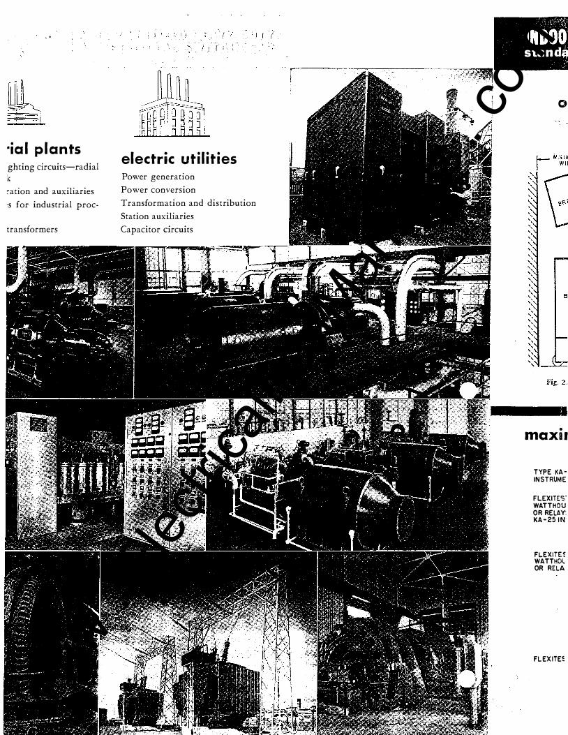
· ia l p lants ghting circuits-radial �
cation and auxiliaries
:s for industrial proc-
transformers
; ; I t' : t
' l [ : :
electric uti l i t ies Power generation
Power conversion
Transformation and distribution
Station auxiliaries
Capacitor circuits
, r·��j?� INDOO stand '
0
• maxu
T YPE KAINSTRUME
FLE XITE'S" WATTHOU OR RELAY: KA - 25 1 N
FLEXITE� WATTHOl OR RELA
FLEX ITE�
www . El
ectric
alPar
tMan
uals
. com

www . El
ectric
alPar
tMan
uals
. com

appl k:at�on f·ab�e n /fg." AVA I LABLE BREAKER TYPES
--�----------------�--------------------------------r-----��------. CURRENT INTERRUPTING II
' 3-PHASE AIR INTER-
CIRCUIT RUPTING
VOLTAGE RATINGS RATINGS IN AMPERES . RATINGS-AMPERES 60 IMPULSE - - !� -- - ____ r____ :-------------------- ! c�i�is Rri:��G
. Min. KV. i i Shor! 1 FOR OR i lor Rated . Conlin- : Time At ONE CLOSED J BREAKER RATING ; ; Max, 1
__ _
__ _:: __ __ !_:VA�
-
: ����-; D��:n · INT. uous Momen- 4 Rated Max, MINUTE GAP I M
3�: · 60
6��--4�:�00- -;::::�0
- :::�:::-• ::�:: -!--�: - :�--� , 5 0-DH- 1 5 0-D . 1 50 : 4 . 1 6
' 4.76 I 5 0-DH- 1 5 0-D 1 5 0 4. 1 6 4.76 I 50-DH- 1 5 0-D 1 5 0 4 . 1 6 4 .76
3.5 1 2 0 0 40,000 2 5,000 2 1 ,000 ' 2 5,000 19 6 0 ! 3 . 5 2 000 40,000 2 5,000 2 1, 0 0 0 2 5,000 ' 1 9 60
5 0-DH- 2 5 0-D 2 50 4. 1 6 4.76 5 0-DH-2 5 0-D 2 50 4 . 1 6 4.76
7 5-DH-2 5 0-A 2 50 7.2 8.2 5
3 . 8 5 1 2 00 6o,ooo 37,500 3 5,ooo 3 7, 3 0 0 1 9 6 o I 3 . 8 5 2ooo 6o,ooo 3 7,5oo 3 5, o o o 3 7,5oo 1 9 6 o I 4 . 6 1 20 0 5 1 ,ooo 32,ooo 2 o,ooo 3 2,ooo 36 9 5 I i 7 5-DH- 2 5 0-A 2 50 7.2 8 . 2 5 4 . 6 2 0 0 0 5 1 ,0 0 0 3 2 ,000 2 0,000 3 2,000 36 9 5 'I
i 7 5-DH- 5 00-A 500 7.2 8 . 2 5 6 . 6 1 20 0 70,000 44,000 4 0, 0 0 0 44,000 3 6 9 5 I 7 5-DH - 5 00-A 5 00 7.2- 8.2 5 I
6 . 6 2 0 0 0 70,000 44,000 4 0, 0 0 0 i 44,000 3 6 9 5 j 1 5 0-DH- 1 5 0-A 1 50 , 1 3. 8 I 1 5 0-DH- 1 5 0-A 1 50 i 1 3.8
I 1 5 0-DH- 2 5 0-A 2 50 1 3.8
1 5 . 0 1 5. 0
1 5.0 1 5.0
6.6 600 ! 20,000 1 3,000 6,3 00 1 3,000 6.6 1 2 0 0 20,000 1 3,000 6, 3 0 0 1 3,000
6.6 1 2 00 3 5, 0 0 0 2 2,000 1 0, 6 0 0 i 2 2,000 6.6 2000 3 5 ,000 2 2,000 1 0,600 i 2 2 ,000
1 1 . 5 1 2 0 0 4 0, 0 0 0 2 5,000 2 1 , 0 0 0 i 2 5,000
36 9 5 3 6 9 5
3 6 9 5 3 6 9 5 I
3 6 9 5 I II � ����:������ ��� � : :: 1 5 .0 1 5 0-DH- 5 00-A 5.00 1 3. 8 1 5.0
, ___
------ 1 1 . 5 2 0 0 0 4 0, 0 0 0 2 5,000 2 1 ,0 0 0 i 2 5 ,000 3 6
1 * For Application Data concerning power circuit breakers, see A. D. 3 3- 1 1 5. ,_ --�-----------------------------------------
9� a pplication table n gn
Type PT POTENTIAL TRANSFORMERS Accuracy Classifications-Mounting Limitations
Potential transformers are Type PT mounted on drawout disconnect drawer assemblies which disconnect both the primary and secondary connections and ground the high-
voltage winding when the door is opened. Available ratings and number of transformers per drawout drawer are indicated below.
-·-- ·---------�----------------------- ·------,
PRIMARY VOLTAGE RATINGS STYLE
NO. CONNECTIONS
50/60 CYCLE DATA __ ------------ ___ _ M A��RANS. P ER �!A�OUT ORA���
IMPULSE RATING
KV.
55°C,
INDOOR OUTDOOR i ----------- --� . I
ACCURACY 60 CYCLE , 25 CYCLE 60 CYCLE ' 25 CYCLE l Ambient CLASSIFICATION ---- -----!----1
Volt- UNIT , UNIT UNIT : UNIT '1 Amperes WIDTH WIDTH WIDTH ! WIDTH Thermal : --- ------------ : , 1 --.--i--,--1
w X y i z ' 26 ! 36 i 26 ! 36 ' 28 : 38 : 28 I 38 ! ----� - --- - ------- --------- . -------- - ______ ,____ ----- , ___ �--!--1--i--;�i--!�i-- !
1 629 9 8 5 ( } 6 0 400 0 . 3 0 . 3 0 . 3 0 .6 3 ; 3 2 3 3 2 I l 2 4 0 0 4 2 00 4800
2 4 0 0 4 2 0 0 4 800
7 2 00 1 2 000 1 44 0 0
2 4 0 0 4 2 0 0 4 8 0 0
7 2 0 0 *69 2 8 *8 3 1 4
1 48 3 7 9 8 i 0 to 0 60 600 0 , 3 0 .3 0 , 3 0,6 2 I 3 2 3 2 2 ! 1 48 3 7 9 9 \
0 ro Grd. 60 600 0 . 3 0.3 0 . 3 0.6 3 3 3 3
1 48 3 8 0 3 0 to 0 9 5 600 2 3 2 1 48 3 8 0 4 0 to 0 9 5 600 2 3 2
0 . 3 0 . 3 0 . 3 0 . 6 3 0 . 3 0.3 0 . 3 0.6 3
1 48 3 8 0 5 0 to 0 9 5 600 2 3 2 0. 3 0.3 0. 3 0.6 3
1 48 3 8 0 0 0 t o 0 9 5 1 4 8 3 8 0 1 0 [0 0 9 5 1 4 8 3 8 0 2 0 t o 0 9 5
1 48 3 794 0 to Grd. 9 5 1 48 3 7 9 5 0 t o Grd. 9 5 1 4 8 3 796 0 to Grd. 9 5
1 4 8 3 7 9 1 0 t o Grd. 9 5 1 48 3 7 9 2 0 t o Grd. 9 5 1 48 3 7 9 3 0 to Grd. 9 5
600 7 5 0 7 5 0
600 600 600
6 0 0 4 5 0 4 5 0
0 . 3 0.3 0.3
0 . 3 I 0 . 3
0 . 3
0 . 3 0 . 3 0 . 3
0 . 3 0 . 3 0 . 3 0 . 3 0.3 0 . 3
0 . 3 0. 3 0 .3 0 .3 0 .3 0. 3
0 .3 0 . 3 0 . 3 0 . 3 0 . 3 0 . 3
0.6 3 0 . 3 3 0.3 3
0.6 3 0 , 6 ' 3 0.6 3
0.6 3 1 .2 3 1 . 2 3
2 2 2 I 2 2 2
I 3 3 3
3 3 3
; 2 2 2
2 2 2
2 3 2 2 3 2 2 3
. . 2
�------ �---� ----· - ·---- ----� -- - - � - - - · ··-�--�- - �� -� - - �---��-----�--�__:_ ______ J__ _ _ _ _ _ , * Line·to:n eutral transformers ...-e fluxed to corresponding line-to-line voltage for grounded wye connection to provide ground detection and relay j.
protection. --...... -�--.. �----·�� .
- -------�--�--.·---------·""·- ... --.... _.., ____ ,..,..,.. �- - - -- -�--·-�- -----
NOTES: L Listed Style Numbered Potential Transformers are for Metal-Clad
Switchgear A pplications. 2 . When Circuit Breakers are Type 5 0-DH- 1 SO or 50-DH-2 5 0
·1· U · flndoor-26" or 36" wide only, Amu •ary mts are--\Outdoor-30" wide only, 3. When Circuit Breakers are 7 5-DH or 1 5 0-DH;
A "li U · llndoor-3 6" wide onlr. ux1 ary n1ts are-- \ Outdooc-38" wide only,
4. Disconnecting Type Potential Transformer Assemblies can be mounted in Outdoor Circuit Breaker Units mdy when Transfer Bus Type A ssem· blies are required. See Fig. 84, Page 2 5.
; , \\"hen three transformers are connected in WYE, the neutral is grounded.
6. For Technical Data on potential transformers, see publication T. D. 4 5 -9 1 0.
www . El
ectric
alPar
tMan
uals
. com

www . El
ectric
alPar
tMan
uals
. com

r · - -, : wm l L. - - .J r---, ' ' 1\1/HMI I I L - _j �
, ., l - � J tJ [J . .
j[ijl biJ i:J 61 [Q] CJ =
ij "
lijl B a ... / \
Ill 0 ' Wl ' I
, _ _ /
EJ EXC. RR. B 8
' 2 6 ---<•o.t-1 .. --- 2 6 ---+--
· 3 6 3 6 ---��--:I: 2 6
J 6
('; "�
H R A T O R
;<""� :;) E X C I T E R F O R
O N E G E N E R A T O R
4 �� I N C O M I N G
l l N E
,""'["'�'"/ J I P.T. }
.-·.,....._, ...... I .:.E 3 c. T.'$ I ;-;
i !
:1 :
�· � .... ,.,,"-� - •v,·� '" • • .. ··'· '·"'""'-'�'�'"""'"" .. ,··,·,· , ·=�""'"'"';_'"'�' o·c•·•= ·
; N E R A T O R
J 2 ·:� '�� : :�;:; D ; UNITIZED switchgear for con•
.) of a single generator with exciter, synchronizing
uipment, and three feeder circuits.
DO DO DO 0"' 1 0 0 ...
� 0 D D IJ D alia " II
ii
o� .. .. . .. ( 0 :: 0 · . .. .. ..
0 I
0
LJ ! ? 0 0 D 7
Fig. 126.
0 ' ' ---
s ij 0 0 0 7
0
...
Iii � 0 0 D 7
r · - .., ; wm : l. � - .l r- -:1 I I - 1WHM1 I I L - _j
, ., ' ·•
[Q] ' d
ij B B 8
2 6
3 6
<'_\. I N C O M I N G
L l N E
88B BBB
3 6
3 6
''"' ;, A U X I L I A R Y
C O M P A R T M E N T
I � - . , :::. : -' I P . T.
-----· "? .. �___.__.� 1 P. T. � ': 3 c.T.'S '
2 P. T.' S
:I:
r - - , t \1/m ' L _ _.J ,.- - -.
:WHM: I I L _ J
. .
(QJ 0 . .
fQl B B 8 2 6 -���---- J & ------��--:I: 3 6 --��----- 3 6 ----��---
I N C O M I N G L l N E
A U X I L I A R Y C O M PA R T M E N T G R O U N D D ET E C T I O N
T O T A L I Z I N G M ET E R I N G
l P . T.'S ·::.-·x=::c•;� G R O U N D : D E T E C T I O N
:�-·�..:. >\.;-..... 2 P. T. '$ M E T E R I N G
2 C . T.' S
7 f E E D E R
� 3 C . T . 'S
7
1 UNITIZED switchgear for control of parallel generators, with exciters, ground detectors, synchronizing equipment, one incoming line,
and four feeders. This becomes a group made up of the following basic units:
� DO I DO DO DO 0 0 0 0 D D 0 D 0
II IE a ""'""
·t 8 � m2ii II !I �
o� - · � �
08 ..... ... '� 0 :: :' 0 ·:
0 .. ·�- 0 ......
0 0 1 3 3
DO D O D . . .
- - - 0 (;] � 0 0 0 4 6
Fig. 1 27.
0 , . .
' ' . . .
13 � 0 0 0 7
0 D 0 , . ,
. . . . . . . . .
r;a 0 (ll 'i � � D 0 0 0 D 0 D 0 0 7 7 7 www .
Elec
tricalP
artM
anua
ls . c
om

•
www . El
ectric
alPar
tMan
uals
. com

= o o fQl G G G
= o a � G G G
/ ' ( 0 � \ I
, _ .... £XC. RH. r - -, 1 I I CA l I I L _ J r - l : CA : L_ J r --, : CA ; I 1 L _ ..J
= 0 0 IQl r - -, I I I CO t I I L _ J r - • I I I CO l I I L _ ..J r - -,
l co : I I . L _ ..J
==::1�:== � : -�:1-:- � : -....!: 1--:- �: -�. �-.. - :: ==:: 1::=-8
I N D U C T I O N M O T O R F U L L V O L T A G E
S T A R T I N G
L f
R o I ,.. .... V I .1£ .. I ..... '
M Oi O R ' -
'
'
9 tO 11 IN D U C T I O N M O T O R . S Y N C H R O N O U S M O T O R R E D U C E D V O L T A G E L I N E S T A R T I N G O R R E D U C E D
S T A R T I N G W I T H V O L T A G E S T A R T I N G W I T H N E U T R A L N E U TR AL R E A C T O R I N R E A C T O R I N S E P A R A T E S T R U C T U R E
'S E P A R A T E S T R U C T U R tlllijlljUiiijjjjltiWJ
f1 0 . :t . ' ..
n ,l, � Q M Q T O R !
.:::- ' T" I --.....- .. - .J
::----1 iJ C . T. ' S I 0 I ... y l : rr
f"' � / .J.. , .C ,...-.· M O T O R • � � ' ..... ' , v .......__ - - J
' '
3. REQUIRED: UNITIZED switchgear for starting a
synchronous motor, for control of two incoming lines with
directional protection, and two feeders.
Q.O d 0
" iii 0 0 0 10
0 0
, ' " ' ,
('��) . ' r: � ' ' . . . : •• .J
II
DO , . , . . . , . , ' ' . . .
., � D 0 0 4
r ·-,,... • .,,. .,r . ., .. ...... .. " . .... -.J
ODD ODD 5
Fig. 1 28
DO .. , ' "
.. " �
0 0 0
0 0 . . , . . , . . . . . .
� "' ii � 0 0 0 0 0 0 7 7
1 2 B U S
S E C T I O N A L I Z I N G U N I T
T , .,J C. T.'S . .. ..,.. 0 .... J
1 3 A UX I L I A R Y
C O M P A R T M E N T M I S C E L L A N E O U S
E Q U I P M E N T
: i ' .,�..:: .. . � ! . . ; � 2 P.T.' S
14 B U S
E N T R A N C E C O M P A R T M E N T.
n I I I + I I ! '
4. REQUIRED: UNITIZED switchgear for a substation with two in
coming lines, two induction motor circuits, two feeders and bus sectionaliz
ing equipment.
DO p 0 0 R DO . . . ' ' . . . 0 · - ·
, ., 0 , . , , . , S, :
0 . . . . . . 0 .. .. ., lil a liJ Ill "' ii � � � � � � 0 0 D ;�! 0 0 D 0 0 0 0 0 0 . . .
0 0 0 ,_ J 0 0 0 .. a 7 13 12 7 8 4
Fig. 1 2 9 43 www .
Elec
tricalP
artM
anua
ls . c
om

www . El
ectric
alPar
tMan
uals
. com

44
Heavy-Duty DH Metal-Clad Switchgear
Indoor and Outdoor
1 • Single-line diagram showing main connections and sketch showing desired order of assembly of units.
2 . Name of manufacturer and complete name plate rating of all equipment to be controlled by the switchgear. Generator information should include the field rheostat, field discharge resistor, governor motor information and exciter rating. Synchronous motor information should include exciter rating.
3. The control voltage, such as 1 2 5- 2 5 0 volts d-e, for operating the solenoid closing mechanism and shunt trip coil.
4 . Type of cable, number and size of conductors and diameter over lead or braid for each power circuit and where they are to enter (top or bottom) .
5 . How power cables are to terminate (clamp terminals or potheads) .
6. Where control cables are to enter (top or bottom) .
7. Maximum over-all dimensions of shipping section which can be handled and installed at destination.
8 . Complete name plate wording for each circuit identification name plate .
. --------- BASIS OF SPECIFICATIONS---------.
The following specifications are based on 3-phase service, with ungrounded or solidly grounded neutral. The panel equipment specified is the minimum essential for the various circuits. Additional instruments and relays may be specified within the space limitations of the panel. See Figs. 2 3 , 33, and 76.
The arrangements which are covered by these specifications are the most common for this class of switchgear. Other arrangements are also available, such as the double bus, double circuit breaker arrangement (Figs. 34 , 46 and 8 3 ), and the main and transfer bus arrangement (Figs. 40, 5 3, and 84) . All other bus arrangements or
GENERAL: Type DH Metal-Clad Switchgear will consist of a stationary housing and a horizontal drawout air circuit breaker, equipped with a solenoid operating mechanism and primary and secondary disconnecting devices, assembled on a frame to form a self-contained and self-supporting mobile unit. The switchgear will be suitable for service up to ( 5000) (7 5 00) ( 1 5,000) volts, as indicated in application table "A" (see page 39), and will receive dielectric �ests in accordance with NEMA standards. The switchgear will be designed, manufactured, and tested in accordance with the latest standards of the AlEE and the NEMA.
special requirements should be referred to a Westinghouse Sales Office for recommendations.
The following specifications are based on units that will �ccommodate 1 200 or 2000-ampere bus capacities. Busses in excess of 2 000 amperes will require increase in depth, as shown in Figs. 36 and 49.
NOTE: The specification is based on d-e, solenoidoperated breakers, as this is the most common and desirable arrangement. A-c operation can be o btained by use of Rectox ® solenoid closing and capacitor tripping device or low-voltage, d-e, battery trip coil. This requires the addition of operating transformers connected to the incoming circuits and bus for operating and control source. Manually operated air circuit breakers are not to be specified in any case.
STATIONARY STRUCTURE: Unit-type construction will be used in the formation of the housing to provide a rigid, self-supporting and self-contained enclosure for each circuit breaker unit. Each stationary structure will be built of Ys-inch thick, formed, stretcher-leveled steel sheets, and structural members, electrically welded, and will have a hinged steel panel suitable for mounting of instruments, meters, relays, and control devices. The circuit breaker unit, busses, instrument transformers, and outgoing cables will be isolated within separate compartments formed by sheet steel barriers. Heavy Micarta bus supports will be mounted over the bus openings between units.
- 4 '
) J www .
Elec
tricalP
artM
anua
ls . c
om

www . El
ectric
alPar
tMan
uals
. com

_j
These close-fitting supports form a barrier which will isolate each unit from adjacent units. Each compartment will have a separate cover for individual servicing without exposing circuits in adjacent compartments.
A metal shutter will automatically close the opening to the insulators for the primary disconnecting devices when the circuit breaker unit reaches the "Disconnect" position. The shutter will be a simple, one-piece unit closed by gravity and raised automatically upon insertion of the air circuit breaker.
The cable compartment in the rear of each housing will be provided with wiping sleeves or Micarta supports for the primary cables, and is adaptable for pothead entrance. Compartment will be arranged for the cables to enter from above or below the housings, as required.
Terminal blocks will be conveniently located for external connections.
The stationary structure and circuit breaker units will be constructed so that each unit is interchangeable with every other unit of similar rating.
The steel work will be Bonderized as a unit after all welding is completed , and painted with a rustresisting primer coat, followed by a light grey interior and exterior finishing coat. The Outdoor Metal-Clad Switchgear will receive a light grey interior coat and a dark grey weather-resistant external finish coat.
The circuit identification name plates will be engraved Anodized aluminum, 1 inch high and 3 inches wide.
BUSSES AND CONNECTIONS: The busses will be made of high-conductivity, flat copper bar having round edges and will be completely insulated with preformed Micarta tubes, two-piece compound-filled Moldarta boxes and varnish cambric taping. The copper at each main bus joint and each tap j oint will be silver-plated and tightly bolted to insure maximum conductivity.
A ground bus with a cross section equal to at least 2 5 percent of the capacity of the largest circuit will extend throughout the length of the Metal-Clad assembly. Each housing will be grounded directly to this bus. The frame of each circuit breaker unit will be grounded through a rugged ground contact shoe at all times, except when the primary disconnecting devices are separated a safe distance.
DISCONNECTING DEVICES: The primary disconnecting device for each high-voltage circuit will consist of a fixed terminal clamped within a Moldarta or porcelain tube, and a moving contact mounted on the circuit breaker stud. All live parts will be enclosed by the Moldarta tube for 5-kv and porcelain tube for 1 5-kv insulation class of equipment.
The moving contact will consist of a flexibly mounted, self-aligned assembly of bridging segments, formed so that each segment will make a high-pressure, two-point contact with the fixed terminal at one end and with the circuit breaker terminal at the other end. All contact surfaces will be heavily silver-plated to prevent reduction in current carrying capacity due to oxidation.
The bridging segment assembly will be a part of the removable circuit breaker unit for easy accessi-bility and inspection.
.
The secondary disconnecting device will provide connections for the control circuits between the circuit breaker unit and the housing and will consist of multiple plug and socket contacts of the train-line coupler type. The secondary disconnect will automatically engage when the circuit breaker is placed in the "Operating" position and can be re-engaged manually when the uclit is in the "Test" position, without using a test jumper.
REMOVABLE ELEMENT: The circuit breaker element will be the Westinghouse Type DH Air Circuit Breaker complete with solenoid operating m echanism, auxiliary switches, and interlocks mounted on a mobile frame. The frame will be fabricated from formed steel plates electrically welded to form a rugged support for the equipment. A horizontal steel barrier will separate the high-v
-oltage p arts of
the circuit breaker from the operating mechanism and control devices. The frame will have four wheels with needle bearings and a special flange construction which will engage with the rail as the unit 1s rolled into the housing.
The breaker unit is moved between the "Test" position and "Operating" position by means of a worm gear levering device that is operated by a removable hand crank. The worm gear levering device is so mechanically interlocked with the breaker closing mechanism, that a closed breaker cannot be removed from the "Operating" position or inserted from the "Test" position. The breaker mechanism cannot be closed ·when the worm gear levering device is between the "Operating" position or the "Test" position of the levering device.
FACTORY ASSEMBLY AND TESTS: The switchgear will be completely assembled, wired, adjusted , and tested at the factory. After complete assembly, each standard unit will be tested for operation under simulated service conditions by impressing primary current on the current transformers. Properly p �ased voltage from the same source will be impressed on the potential circuits. This assures accuracy of the wiring, correctness of the control scheme and functioning of the equipment.
45 www . El
ectric
alPar
tMan
uals
. com

f '
www . El
ectric
alPar
tMan
uals
. com

�l L2J
SWI NGI N G INSTRUMENT PANEL
A swinging steel instrument panel will be mounted on the (right) (left) hand end of the structure for synchronizing instruments. The panel will be 2 (Yz inches wide and 24 inches high and will be equipped with the following:
FOR CONTR O L O F ONE GENERATO R
The Metal-Clad Switchgear for the control of one generator an d one exciter will consist of two housings which will provide switching, instrumentation, voltage regulation and excitation control. The Metal-Clad Unit for the control of one 3-phase, 60-cycle generator will be . . . . . . inches wide, . . . . . . inches deep, 90% inches high, and will be equipped with the following: 1-Type DH air circuit breaker, . . . . . . am-
pere, 3-pole, single-throw, d-e, solenoid operated.
1-Set of . . . . . . ampere insulated busses. 3-Current transformers, . . . . . . I 5 I 5 ratio,
double secondary ( 5 kv) ( 1 5 kv) . 3-Current transformers, . . . . . . I 5 single sec-
ondary ( 5 kv) ( 1 5 kv) for generator neutral unmounted.
Mounted on the hinged instrument panel:
1-Type KY- 2 5 power-factor meter, 50- 1 00-5 0 scale.
The auxiliary compartment for the control of the exciter will be . . . . . . inches wide, . . . . . . inches deep and 90% inches high, and will be equipped with the following:
NOTE: The 2 6-inch auxiliary compartment is suitable for a total of two sets of three each, of 2400/ 1 2 0 volt potential transformers or two sets of two each, of 42001 1 20 volt potential transformers.
1-Set of . . . . . . ampere insulated busses.
1-Electrically operated disconnecting Type DB field breaker.
2-Disconnecting Type PT potential trans-formers . . . . . . / 1 20 volt ratio, 60-cycle, with fuse mountings, and one set of current limiting fuses. (To be connected to the generator circuit for metering.)
1-Disconnecting Type PT potential transformer, . . • . . . / 1 2 0 volt ratio, 60-cycle, with fuse mountings, and one set of current limiting fuses. (To be connected
2-Type KA-25 voltmeters, 0 - . . . . . . volt scale, 1 5 0-volt coils.
1-Type KI-25 synchroscope with two lamps. 1-(0ptional) Type KY-2 5 frequency 10-
dicator, 5 8-62 cycle scale, 1 1 5 -volt.
1-Type KA-25 a-c ammeter, 0- . . . . . . scale, 5-ampere coil.
1-Type KY- 2 5 polyphase indicating wattmeter, 0- . . . . . . scale, 5-ampere, 1 1 5-volt.
1-Type CB-2F Flexitest polyphase watthour meter, 2-element, 5-ampere, 1 20-volt, with built-in test switches.
3-Type CA Flexitest generator differential relays, with built-in test switches.
1-Type WL auxiliary tripping relay. 1-Type W 3-phase voltmeter switch. 1-Type W 3-phase ammeter switch. 1-Type W synchronizing switch. 1-Type W rheostat control switch. 1-Type W field breaker control switch with
red and green indicating lights. 1-Type W governor motor control switch. 1-;-Type W circuit breaker control switch
with red and green indicating lamps for generator air circuit breaker.
1-Name plate for circuit identification.
to the generator circuit for voltage regulator.)
Mounted on the hinged instrument panel:
1-Type KX-25 d-e voltmeter, 0- . . . . . . scale. 1-Type KX-25 d-e ammeter, complete with
5 0 mv shunt, 0- . . . . . . scale. 1-Type KX-2 5 temperature indicator, 0- 1 50
degrees C scale, complete with Rectox unit.
1-Type SRA-( 1) (2) (3) ( 4), direct, quickacting (Si!Yerstat®) generator voltage regulator with voltage adjusting rheostat, damping transformer, and provision for cross current compensation.
1-Type W temperature indicator switch. 1-Type W regulator transfer switch. 1-Type W exciter rheostat control switch, or
1-Manual mechanism for operation of ex-citer field rheostat and drilling only for mounting of rheostats. ( 2-1 5-inch diameter plates maximum.)
� I I i
I
r '
) www . El
ectric
alPar
tMan
uals
. com

www . El
ectric
alPar
tMan
uals
. com
·., j
' <
FOR CONTROL O F O N E I N COMING L I N E
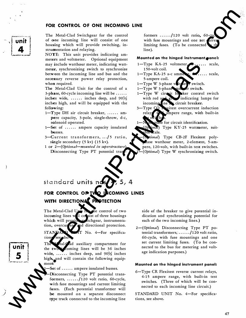
The Metal-Clad Switchgear for the control of one incoming line will consist of one housing which will provide switching, instrumentation and relaying. NOTE: This unit provides indicating ammeters and voltmeter. Optional equipment may include watthour meter, indicating wattmeter, synchronizing switch to synchronize between the incoming line and bus and the necessary reverse power relay protection, when required. The Metal-Clad Unit for the control of a 3-phase, 60-cycle incoming line will be . . . . . . inches wide, . . . . . . inches deep, and 90% inches high, and will be equipped with the following: 1-Type DH air circuit breaker, . . . . . . am-
pere capacity, 3 -pole, single-throw, d-e, solenoid operated.
1-Set of . . . . . . ampere capacity insulated busses.
3-C u r r e n t t r a n s fo r m e r s , . . . / 5 ra t i o , single secondary ( 5 kv) ( 1 5 kv).
1 or 2-(0ptional-mounted in superstructu,-e)
Disconnecting Type PT potential trans-
s t a n d a rd u n its n os. 4 , 5 , 4
formers . . . . . . / 1 2 0 volt ratio. 60-cycle, with fuse mountings and one set current limiting fuses. (To be connected to the line).
Mounted on the hinged instrument panel:
1-Type KA- 2 5 voltmeter, 0- . . • . . , scale, 1 5 0-volt coil.
1-Type KA- 2 5 a-c ammeter, 0- . . • . . . scale, 5-ampere coil.
1-Type W 3-phase voltmeter switch. 1-Type W 3-phase ammeter switch. 1-Type W circuit breaker control switch
with red and green indicating lamps for incoming line air circuit breaker.
3-Type CO Flexitest overcurrent induction relays, 4- 1 5 ampere range, with built-in test switches.
1-N arne plate for circuit identification. 1-(0ptional) Type KY- 2 5 wattmeter, suit
able scale. 1-(0ptional) Type CB-2F Flexitest poly
phase watthour meter, 2-element, 5 -ampere, 1 20-volt, with built-in test switches.
1-(0ptional) Type W synchronizing switch.
FOR CONTROL O F TWO I N COMIN G L I N ES
Wlnt D I RECTI ONAL PROTECTION
The Metal-Clad Unit for the control of two incoming lines will consist of three housings which will provide switchgear, instrumentation� overcurrent and directional protection.
STANDARD UNIT No. 4-For specifications, see above.
The Metal-Clad auxiliary compartment for the two incoming lines will be 36 inches wide, . . . . . . inches deep, and 90% inches hig� and will contain the following equipment: 1-Set of . . . . . . ampere insulated busses.
2-Disconnecting Type PT potential trans-formers, . . . . . . / 1 2 0 volt ratio, 60-cycle, with fuse mountings and current limiting fuses. (Each potential transformer will be mounted on a separate disconnect type truck connected to the incoming line
side of the breaker to give potential indication and synchronizing potential for each of the two incoming lines.)
2-(0ptional) Disconnecting Type PT po-tential transformers; . . . . . . / 1 20 volt ratio, 60-cycle, with fuse mountings and one set current limiting fuses. (To be connected to the bus for metering and voltage indication purposes.)
Mounted on the hinged instrument panel:
6-Type CR Flexitest reverse current relays, 4- 1 5 ampere range, with built-in test switches. (Three of which will be connected to each incoming line circuit.)
STANDARD UNIT No. 4-For specifications, see above.
47
www . El
ectric
alPar
tMan
uals
. com

www . El
ectric
alPar
tMan
uals
. com

' .
unit 6
:"<.o,#i.�W:,f'J.:-;;;�··.-.:�-�i · unit r i ' 8 f ;;::.-,...;.-�-;lo;(...¥:� '�"'"""-+*-
AUXILIARY COMPARTMENT
The auxiliary compartment for the totalizing equipment will be 36 inches wide, . . . . . . inches deep, and 90% inches high, with provision for the following equipment: 1-Sct of . . . . . . ampere insulated busses
and connections. 2-Current transformers , . . . . . . I 5 ratio,
single secondary, (5 kv) ( 1 5 kv). 2-Disconnecting Type PT potential trans-
formers, . . . . . . I 1 2 0 volt ratio, 60-cycle, with fuse mountings and one set of current limiting fuses. (To be connected to the bus.)
3-Disconnecting Type PT potential trans-formers, . . . . . . I 1 2 0 volt ratio, 60-cycle,
FOR CONTROL OF ONE FEEDER
The Metal-Clad Switchgear for the control of one feeder circuit will consist of one housing which will provide switching, instrumentation, and relaying. The Metal-Clad Unit for the control of a 3 -phase, 60-cycle feeder circuit will be . . . . . . inches wide, . . . . . . inches deep, 90% inches high, and will be equipped with the following: 1-Type DH air circuit breaker, . . . . . . am-
pere, 3-pole, single-throw, d-e, solenoid operated.
1-Set of . . . . . . ampere insulated busses. 3-Current transformers, . . . . . . 15 ampere
ratio, single secondary (5 kv) ( 1 5 kv) . 2-(0ptional-mounted in superstructure) Dis
connect Type PT potential transformers, . . . . . . 1 1 20 volt ratio, 60-cycle, with fuse
with fuse mountings and one set of current limiting fuses. (To be connected to the bus y-y for ground detector voltmeters.)
Mounted on the hinged instrument panel:
3-Type RA-37 voltmeters, 0- . . . . . . scale. (To be connected for ground indication.)
1-Type R-2 recording demand watthour meter, 2-element, 5 -ampere, 1 20-volt, complete with Type FT test switches. Space only for mounting other indicating or recording meters or instruments, within the limitations of the panel as shown in Figs. 23, 3 3, and 76 .
mountings, and one set current limiting fuses.
Mounted on the hinged instrument panel:
1-Type KA-2 5 ammeter, 0- . . . . . . scale, 5 -ampere coil.
3-Type CO Flexitest over current induction .. relays, 4- 1 5 ampere range, with built-in
test switches and 20-80 ampere instantaneous trip attachment.
1-Type W 3-phase ammeter switch. 1-Type W circuit breaker control switch
with red and green indicating lamps. 1-Name plate for circuit identification. !-(Optional) Type CB-2F Flexitest polyphase
watthour meter, 2 -element, 5 -ampere, 1 20-volt, with built-in test switches.
FOR CONTROL OF INDUCTION MOTOR
(Full Voltag e Starting)
The Metal-Clad Switchgear for the control of one across-the-line starting circuit will consist of one housing which will provide switching, instrumentation and relaying. The Metal-Clad Unit for the control of a 3 -phase, 60-cycle induction motor circuit will be . . . . . . inches wide, . . . . . . inches deep and 90% inches high, and will be equipped with the following: 1-Type DH air circuit breaker, . . . . . . am-
pere, 3-pole, single-throw, d-e, solenoid operated.
1-Set of . . . . . . ampere insulated busses. 3-Current transformers, . . . . . . /5 ampere
ratio, single secondary (5 kv) ( 1 5 kv) . 2-(0ptio11al-mounted i11 superstructure) Dis
connecting Type PT potential trans· formers, . . . . . . I 1 2 0 volt ratio, 60-cycle, with fuse mountings, and one set current limiting fuses.
. .-i www . El
ectric
alPar
tMan
uals
. com

www . El
ectric
alPar
tMan
uals
. com

)
' \
Mounted on the hinged instrument panel:
1-Type KA-2 5 a-c ammeter, 0- . . . . . . scale, 5-ampere coil.
1-Type CV Flexitest a-c undervoltage relay, with built-in test switches.
2-Type BL Flexitest thermal relays, with instantaneous trip attachments, and builtin test switches. (Two Type BL thermal elements mounted in one flush mounted relay case.)
3-Type CO Flexitest overcurrent induction relays, 4- 1 5 ampere range, long time, with built-in test switches and 20-80 ampere instantaneous trip attachment.
1-Type W 3-phase ammeter switch. 1-Type W circuit breaker control switch
with red and green indicating lamps. 1-Name plate for circuit identification. 1-(0ptio1lal) Type CB-2F polyphase watt
hour meter, 2-element, 5 -ampere, 1 2 0-volt, complete with test switches.
FOR CONTROL OF I NDUCTION MOTOR
(Reduced Voltage Starting)
The Metal-Clad Switchgear, for the control of one induction motor reduced voltage starting unit, will consist of one housing which will provide switching, instrumentation, and relaying.
The Metal-Clad Unit for the control of a 3 -phase, reduced voltage starting unit will be . . . . . . inches wide, . . . . . . inches deep, and 90% inches high and will be equipped with the following:
1-Type DH air circuit breaker, . . . . . . ampere, 3 -pole, single-throw, d-e, solenoid operated.
1-Set of . . . . . . ampere insulated busses.
3-Current transformers, . . . . . . f5 ampere ratio, single secondary ( 5 kv) ( 1 5 kv).
2-(0ptional-mounted in superstmcture) Disconnecting Type PT potential transform-ers, . . . . . . / 1 2 0 volt ratio, 60-cycle, with fuse mountings, and one set current limiting fuses.
Mounted on the hinged instrument panel:
1-Type KA- 2 5 a-c ammeter, 0- . . . . . . scale, 5-ampere coil.
1-Type CV Flexitest undervoltage relay, with built-in test switches.
2-Type BL Flexitest thermal relays, with instantaneous trip attachments, and builtin test switches. (Two BL thermal relay elements mounted in one flush mounted relay case.)
1-Type TK Flexitest timing relay, with builtin test switches, for automatic operation of the shunting breaker for the starting reactors.
3-Type CO Flexitest overcurrent induction relays, 4- 1 5 ampere range, long time, with built-in test switches and 20-80 ampere instantaneous trip attachment.
1-Type W 3-phase ammeter switch. 1-Type W circuit breaker control switch
with red and green indicating lamps. 1-Name plate for circuit identification. 1-(0ptio1lal) Type CB-2F Flexitest polyphase
watthour meter, 2-element, 5-ampere, 1 20-volt, with built-in test switches.
u n� t n o . 9-A. rzot-361 I 90� '" ""'"" l
FRONT BREAKER SECTION REACTOR N E UTRAL REACTOR START I N G AUXILI ARY COMPARTMENT FOR
S H I ELDED AIR CORE REACTOR. SPACE SHOWN SUITABLE U P TO APPRO X I M ATELY 2500 H.P. MOTOR
Fig. 1 30.
The auxiliary structure for the starting reactor and starting reactor shunting breaker will be . . . . . . inches wide, . . . . . . inches deep, 90% inches high, and will be equipped with the following: 1-Type DH air circuit breaker, . . . . . . am-
pere, 2 -pole, single-throw, d-e, solenoid operated.
1-Space for starting reactor, 3 -phase, . . . . . . ampere, . . . . . . kv.
1-Set of . . . . . . ampere insulated connections.
1-Set of cable clamps and terminals.
49 www . El
ectric
alPar
tMan
uals
. com

:
www . El
ectric
alPar
tMan
uals
. com

..
FOR C O NTROL OF SYNCHRONOUS MOTOR
The Metal-Clad Switchgear for full voltage or reduced voltage starting of one synchronous motor will consist of two housings which will provide switching, automatic field application, instrumentation, and shutdown upon occurrence of overcurrent, thermal overload, undervoltage, synchronous speed pullout, field failure, and incomplete starting sequence. The Metal-Clad Unit containing the circuit breaker for the control of a 3-phase, 60-cycle, full voltage or reduced voltage starting synchronous motor will be . . . . . . inches wide, . . . . . . inches deep, and 90% inches high, and will be equipped with the following:
1-Type DH air circuit breaker, . . . . . . am-pere, 3 -pole, single-throw, d-e, solenoid operated.
1-Set of . . . . . . ampere insulated busses. 3-Current transformers, . . . . . . /5 ratio,
single secondary (5 kv) ( 1 5 kv). 2-(0ptional-mormted in superstructure) Dis
connecting Type PT potential trans-formers . . . . . . / 1 2 0 volt ratio, 60-cycle, with fuse mountings and one set current limiting fuses.
This compartment can be located in the main structure lineup as shown, or arranged for separate mounting adjacent to the motor.
When supplied for remote mounting for reduced voltage starting application, the field equipment will be mounted on the reduced voltage starting structure, Unit 1 1 -A. When compartment is removed from main structure, field rheostat, when required, must be electrically operated and rheostat control switch added to main panel Unit No. 1 0.
The auxiliary compartment for the control of the motor field circuit will be . . . . . . inches wide, . . . . . . inches deep, and 90% inches high and will be equipped with the following:
1-Set of . . . . . . ampere insulated busses. !-Synchronous motor field panel, consisting
of the following:
1-Type HI field failure relay. 1-Shunt for field ammeter. 1-Type DN field contactor, for field cur
rents of 1 2 5 amperes or less.
or 1-Electrically operated disconnecting
Mounted on the hinged instrument panel:
1-Type KY-2 5 polyphase, reactive voltampere indicator, 0- . . . . . . scale, 5-ampere, 120-volt.
1-Type KA-2 5 a-c ammeter, 0- . . . . . . scale, 5 -ampere coil.
1-Type CV Flexitest undervoltage induction relay, 1 20 volts, with built-in test switches.
2-Type BL Flexitest thermal overload relays, with instantaneous trip attachments, and built-in test switches. (Two BL overload thermal elements mounted in one flush relay case.)
3-Type CO Flexitest overcurrent, long time, induction relays, 4-1 5 ampere range, with built-in test switches and 20-80 ampere instantaneous trip attachment.
1-Type W 3-phase ammeter switch. 1-Type W circuit breaker control switch,
with red and green indicating lamps. 1-Name plate for circuit identification. 1-(0ptional) Type CB-2F Flexitest polyphase
watthour meter, 2-element, 5-ampere, 1 20-volt, with built-in test switches.
1-(0ptional) Type W rheostat control switch.
Type DB field breaker for field currents greater than 1 2 5 amperes.
1-Field discharge and starting resistor. 1-Field application relay. 2-( Optional) Disconnecting Type PT
potential transformers, . . . . . . / 1 2 0 volt ratio, 60-cycle, with fuse mountings and one set of current limiting fuses.
Mounted on the hinged instrument panel:
1-Type KX-25 ammeter, 0- . . . . . . scale for motor field.
1-Type TK Flexitest timing relay, with built-in test switches, for field application over-all sequence checking.
1-Manual mechanism for operation of exciter field rheostat and drilling only for mounting of rheostats, maximum size, 2-1 5-inch diameter plates, or one type W switch for electrically operated rheostats , when size exceeds two 1 5-inch diameter plates.
3 -(Optional) Type "CA" Flexitest ratio differential relays, with built-in test switches.
) www . El
ectric
alPar
tMan
uals
. com

•
www . El
ectric
alPar
tMan
uals
. com

• ,' .
J u�
I ._____.______.190�
DISCHARGE RES ISTOR
� FRONT REACTOR N EUTRAL REACTOR START I N G A U X I LIARY C O M PARTMENT FOR
S H I ELDED AIR CORE REACTOR. SPACE SHOWN SUITABLE UP TO APPROX I M ATELY 2500 H.P. M OTOR
Fig. 1 3 1 .
The auxiliary structure for the starting reactor and starting reactor shunting breaker will be . . . . . . inches wide, . . . . . . inches deep, 90%
CONTROL FOR BUS SECTIONALIZI NG
The Metal-Clad Unit for the control of the bus sectionalizing circuits will be . . . . . .
inches wide, . . . . . . inches deep, and 90% inches high, and will be equipped with the following:
1-Type DH air circuit breaker, . . . . . . am-pere, 3 -pole, single-throw, d-e, solenoid operated.
1-Set of . . . . . . ampere insulated busses and transition bus connections.
3-(0ptional) Current transformers, /5 ratio, single secondary (5 kv) ( 1 5 kv) .
2-(0ptional-mounted in superstructure) Disconnecting Type PT potential transform-ers, . . . . . . / 1 20 volt ratio, 60-cycle, with fuse mountings and one set current limiting fuses.
AUXI LIARY COMPARTMENT
The auxiliary compartment will enclose one set of insulated primary transition bus connections associated with the bus sectionalizing breaker unit and one set of insulated main bus and connections. Space will be available when required for mounting current transformers in the transition connections, a disconnecting type potential transformer as-
BUS ENTRANCE COMPARTMENT
The bus entrance compartment will be mounted on the (right) (left) hand end of the switchgear structure and will provide an
inches high, and will be equipped with the following:
1-Type DH air circuit breaker, . . . . . . am-pere, 2-pole, single-throw, d-e, solenoid operated .
1-Space for shielded air core starting re-actor, 3-phase, . . . . . . ampere, . . . . . . kv.
1-Setof . . . . . . ampere insulated connections.
1-Set of cable clamps and terminals.
1-Type TK Flexitest timing rela.y, with built-in test switches, for closing running breaker.
3-(0ptional) Type CA Flexitest ratio differential relays, with built-in test switches.
Mounted on the hinged instrument panel:
1-Type W circuit breaker control switch, with red and green indicating lamps.
1-Name plate for circuit identification.
3-(0ptional) Type CO Flexitest overcurrent induction relays, 4- 1 5 ampere range with built-in test switches.
!-(Optional) Type W synchronizing switch.
NOTE: An auxiliary unit is required for the bus transition connectors of the bus sectionalizing unit. When an auxiliary unit is not included in the switchgear assembly that can be used for bus transition connections, auxiliary unit Nq. 1 3 must be added.
sembly or an operating transformer for control power with its associated disconnecting type "BAL" fuse assembly, surge protective equipment or other equipment associated with the Metal-Clad Switchgear.
The housing for an auxiliary compartment will be . . . . . . inches wide, . . . . . . inches deep, and 90% inches high.
enclosure for incoming cables which are to connect directly to the main bus.
5 1
www . El
ectric
alPar
tMan
uals
. com

• I ',
www . El
ectric
alPar
tMan
uals
. com

•' l
0: CC G S S-0: rf 6 s- INDOOR AND OUTDOOR
One set of accessories for the operation, test and inspection of the circuit breakers, which will include the following:
KNOCKOUT FOR 1;i- INCH
CONDUIT MAY ENTER TOP
OR BOTTOM OF CABI N E T
COVER 9" is D I A . ( 4 HOLES)
tl FOR WALL MTG. r ...,==·=IJ=== \� -,--'-- I f.-
MOUNT APPROX. 60" FROM FLOOR 35
B R E A K E R
� F R O N T J
"AE!" l2 tLlE�310 � 2 �17 8 201 6
Fig. 1 3 2.
1-Test cabinet, complete with secondary contacts, control relay and pushbuttons for electricallyoperated breakers (see Fig. 1 32).
1-Closing lever for manually closing the circuit breaker.
!-Removable hand crank for operation of the levering-in device.
1-Set of special wrenches, for the primary disconnecting devices.
1-Set test plugs for Flexitest meters and relays. !-Adjustable transport truck for Outdoor Metal-
Clad Switchgear installations only, or !-Transport dolly for indoor installations. NOTE: For outdoor installations, a 1 0-foot test jumper is usually substituted for the test cabinet.
1 2 5 -VOLT CONTROL BATTERY
The control battery will provide power for operation of electrical operating mechanism and may be used for all indicating lamps and any alarm circuits. 1-60-cell storage battery, acid type with pasted
plate assembly in sealed glass jars. Discharge rate will not be less than . . . amperes for one minute or . . . am peres for 8 hours to 1. 7 5 volts per cell. There will also be furnished electrolyte, inter-connectors, two-step rack, cell numbers, portable hydrometer and vent hole thermometer.
24-VOLT TRI PPING BATTERY
:The tripping battery will provide power for operation of the shunt trip coils of Metal-Clad Switchgear installations when a-c Rectox solenoid operating mechanisms are supplied.
1-1 2-cell storage battery, acid-type, with pasted plate assembly in sealed glass jars. The discharge rate will not be less than . . . amperes for one minute or . . . amperes for 8 hours to 1. 7 5 volts per cell. There will also be furnished the electrolyte and inter-connectors.
A-C TRI PP I N G A 24-volt tripping battery i s recommended as the most reliable method for Rectox operated breakers. Where local conditions make the tripping battery undesirable, specify a capacitor trip device for each breaker. In addition, a potential transformer or operating transformer must be available on the line side of each incoming line and generator unit, and on each bus section, to insure a-c supply to the capacitor trip device before its respective breaker is closed.
BATTERY CHARGER FOR 1 2 5 -VOLT CONTROL BATTERY Nonautomatic Chargers 1-Rectox battery charger, 1 1 5 -volt, 60-cycle, a-c
and 0. 1 to 3 . 0-ampere, d-e, complete with dial, switch and ammeter suitable for wall mounting S# 708909, or
1-Rectox battery charger, 1 1 5 -volt, 60-cycle, a-c and 0.2 to 6.0-ampere, d-e, complete with dial, switch, ammeter, voltmeter and suitable for floor mounting. S# 897720.
RECTOMATIC SELF-REGULA'TING BATTERY CHARGER 1-Rectomatic battery charger 1 1 5-volt, 60-cycle, a-c
and 0. 3 to 3. 0-ampere, d-e, complete with indicating and control devices. Floor mounting s* 1 5 49708, or
1-Rectomatic battery charger 1 1 5-volt, 60-cycle, a-c and 0.6 to 6.0-ampere, d-e, complete with indicating and control devices. Floor mounting S# 1 5 49726.
A-C CLOSING A full-wave Rectox rectifier for each breaker will provide the necessary d-e power for operating the solenoid closing mechanism. One 2,400/2 50/120 volt, operating transformer i s required for each incoming line and generator unit and each bus section.
BATTERY CHARGER FOR 2 4 -VOLT TRI PPING BATTERY 1-ReGtox battery charger, 1 1 5-volt, 60-cycle, a-c
and 0 . 1 to 1 . 0-ampere, d-e, complete with ammeter, voltmeter, rheostat and suitable for wall mounting. s� 1 5 5 1 6 50.
SURGE AND LIGHTING PROTECTION Where there are exposed lines, it is recommended that the purchaser provide adequate surge and lightning protection. If desired, this protective equipment can be supplied in the Metal-Clad Gear.
) www . El
ectric
alPar
tMan
uals
. com

www . El
ectric
alPar
tMan
uals
. com

"•_
'· l •
-�
•
·. '
These installations are typical of h undreds of \\'estinghouse Metal-Clad Swirchgear uoits-whereYer large blo cks of power are h andled and controlled,
UTfLITIES
STEEL MILLS
PAPER MILLS
---- -------------ifr----------- ----
/ j
UTIUTIES
POWER PLANTS
METAL MINING
LUMBER MILLS
----------- -----
--- ---------
www . El
ectric
alPar
tMan
uals
. com

• ..
www . El
ectric
alPar
tMan
uals
. com