Embed Size (px)
Citation preview
WF121 CONFIGURATION
DEVELOPER GUIDE
Thursday, 24 November 2016
Version 3.0
Silicon Labs Page of 3 33
Table of Contents
1 Version History ________________________________________________________________________ 42 Project configuration file _________________________________________________________________ 5
2.1 <hardware> ______________________________________________________________________ 52.2 <scripting> _______________________________________________________________________ 52.3 <image> _________________________________________________________________________ 52.4 <bootloader> _____________________________________________________________________ 62.5 <files> ___________________________________________________________________________ 82.6 Examples ________________________________________________________________________ 9
3 Hardware configuration file ______________________________________________________________ 103.1 <adc> __________________________________________________________________________ 103.2 <i2c> ___________________________________________________________________________ 103.3 <notify> _________________________________________________________________________ 123.4 <port> __________________________________________________________________________ 133.5 <sleep> _________________________________________________________________________ 143.6 <spi> ___________________________________________________________________________ 143.7 <timer> _________________________________________________________________________ 173.8 <uart> __________________________________________________________________________ 183.9 <usb> __________________________________________________________________________ 203.10 <ethernet> _____________________________________________________________________ 213.11 <sdhc> ________________________________________________________________________ 213.12 Example configurations ___________________________________________________________ 23
3.12.1 Using BGAPI over UART interface ____________________________________________ 233.12.2 Using BGAPI over USB/CDC interface _________________________________________ 233.12.3 Using BGAPI over SPI slave interface _________________________________________ 233.12.4 Using BGAPI over UART and enabling I2C peripheral interface _____________________ 233.12.5 Using BGAPI over UART2 and enabling UART1 to BGScript application ______________ 243.12.6 Using Ethernet interface ____________________________________________________ 24
4 WF121 Factory Configuration ____________________________________________________________ 255 Compiling a Project into a Firmware Image __________________________________________________ 276 Installing the Firmware _________________________________________________________________ 29
6.1 Using PICkit 3 ____________________________________________________________________ 296.2 Using Microchip IPE _______________________________________________________________ 306.3 Using DFU over UART or USB _______________________________________________________ 31
7 References __________________________________________________________________________ 32
Silicon Labs Page of 4 33
1 Version History
Version Comments
1.0 Updated to match v.1.0 software
1.1 Sleep mode configuration documentation improved
1.2 HTTP server and other configurations added
1.3 WF121 factory default configuration added
1.4 Minor improvements
1.5 Added new Wi-Fi software profile
1.6 Added firmware compilation and installation instructions
1.7 Updated to match v.1.2 software
1.8 Updates for Wi-FI software v. 1.2.2 and editorial changes
Watchdog timer (WDTPS) configuration added
1.9 Ethernet configuration added
2.0 Updated for 1.3 SW compatibility with the following changes:
<certificates> configuration added for including server certificates<sdhc> configuration added for including an external SD cardExternal crystal, e.g., for host communication (USB, UART) configurable under <bootloader><software> configuration removed as SW profile not configurable anymoreEmbedded HTTP server chapter removed as from WiFi 1.3 SW onwards, the embedded web and HTTP server design not tied to specific files and PS keys
2.1 Updated to match v1.3 software
SPI DFU boot loader added under <bootloader>
2.2 Updated to match v1.3 release software
Removed X509 certificate contentAdded warning of SPI data mode unreliability
3.0 Updated for v1.4 release software
Added advice of UART flow control usageAdded description of Microchip IPE usageMinor updates and correctionsText spelling and formatting correctionsChanges in description of ADC pin configuration
Silicon Labs Page of 5 33
2 Project configuration file
The project configuration file (typically ) is the file that describes all the components included in a Wi-project.xmlFi software and hardware project. Typically the project configuration file contains at least the following files:
Hardware configuration file: hardware.xmlOptional BGScript application code: script.bgsOptional HTTP server files
The project configuration file also defines names of generated firmware files and included bootloader file.
The project file itself is a simple XML file with just few tags on it, which are described below.
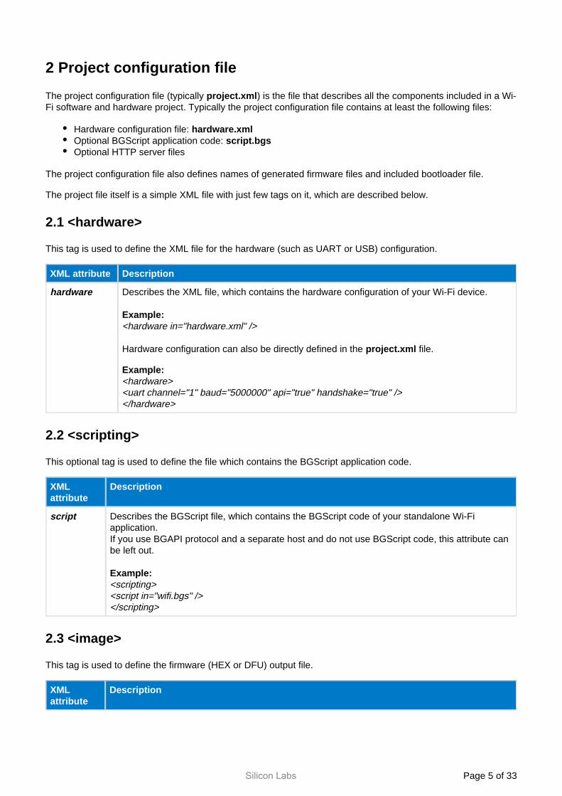
2.1 <hardware>
This tag is used to define the XML file for the hardware (such as UART or USB) configuration.
XML attribute Description
hardware Describes the XML file, which contains the hardware configuration of your Wi-Fi device.
Example:<hardware in="hardware.xml" />
Hardware configuration can also be directly defined in the file.project.xml
Example:<hardware><uart channel="1" baud="5000000" api="true" handshake="true" /></hardware>
2.2 <scripting>
This optional tag is used to define the file which contains the BGScript application code.
XML attribute
Description
script Describes the BGScript file, which contains the BGScript code of your standalone Wi-Fi application.If you use BGAPI protocol and a separate host and do not use BGScript code, this attribute can be left out.
Example:<scripting> <script in="wifi.bgs" /> </scripting>
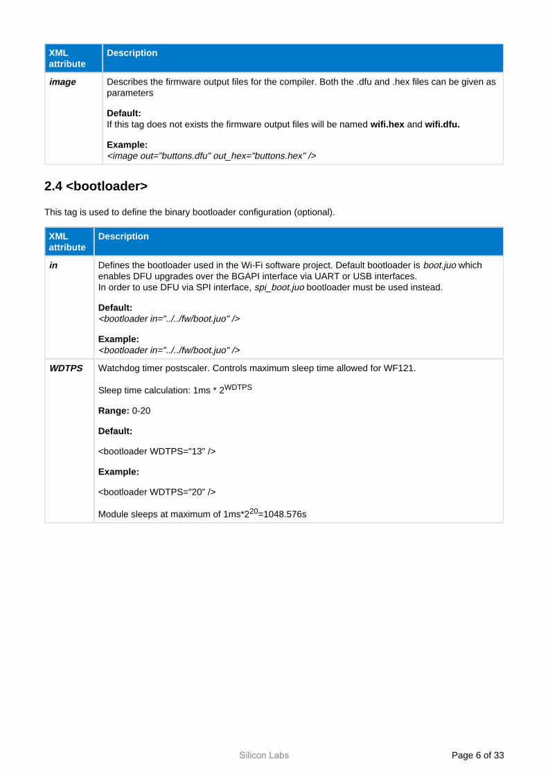
2.3 <image>
This tag is used to define the firmware (HEX or DFU) output file.
XML attribute
Description
Silicon Labs Page of 6 33
XML attribute
Description
image Describes the firmware output files for the compiler. Both the .dfu and .hex files can be given as parameters
Default:If this tag does not exists the firmware output files will be named and wifi.hex wifi.dfu.
Example:<image out="buttons.dfu" out_hex="buttons.hex" />
2.4 <bootloader>
This tag is used to define the binary bootloader configuration (optional).
XML attribute
Description
in Defines the bootloader used in the Wi-Fi software project. Default bootloader is which boot.juoenables DFU upgrades over the BGAPI interface via UART or USB interfaces.In order to use DFU via SPI interface, bootloader must be used instead.spi_boot.juo
Default:<bootloader in="../../fw/boot.juo" />
Example:<bootloader in=" boot.juo" />../../fw/
WDTPS Watchdog timer postscaler. Controls maximum sleep time allowed for WF121.
Sleep time calculation: 1ms * 2WDTPS
Range: 0-20
Default:
<bootloader WDTPS="13" />
Example:
<bootloader WDTPS="20" />
Module sleeps at maximum of 1ms*2 =1048.576s20
Silicon Labs Page of 7 33
XML attribute
Description
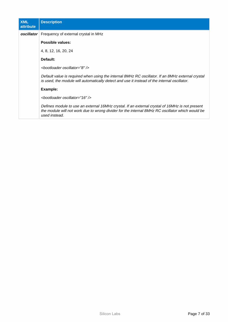
oscillator Frequency of external crystal in MHz
Possible values:
4, 8, 12, 16, 20, 24
Default:
<bootloader oscillator="8" />
Default value is required when using the internal 8MHz RC oscillator. If an 8MHz external crystal is used, the module will automatically detect and use it instead of the internal oscillator.
Example:
<bootloader oscillator="16" />
Defines module to use an external 16MHz crystal. If an external crystal of 16MHz is not present the module will not work due to wrong divider for the internal 8MHz RC oscillator which would be used instead.
Silicon Labs Page of 8 33
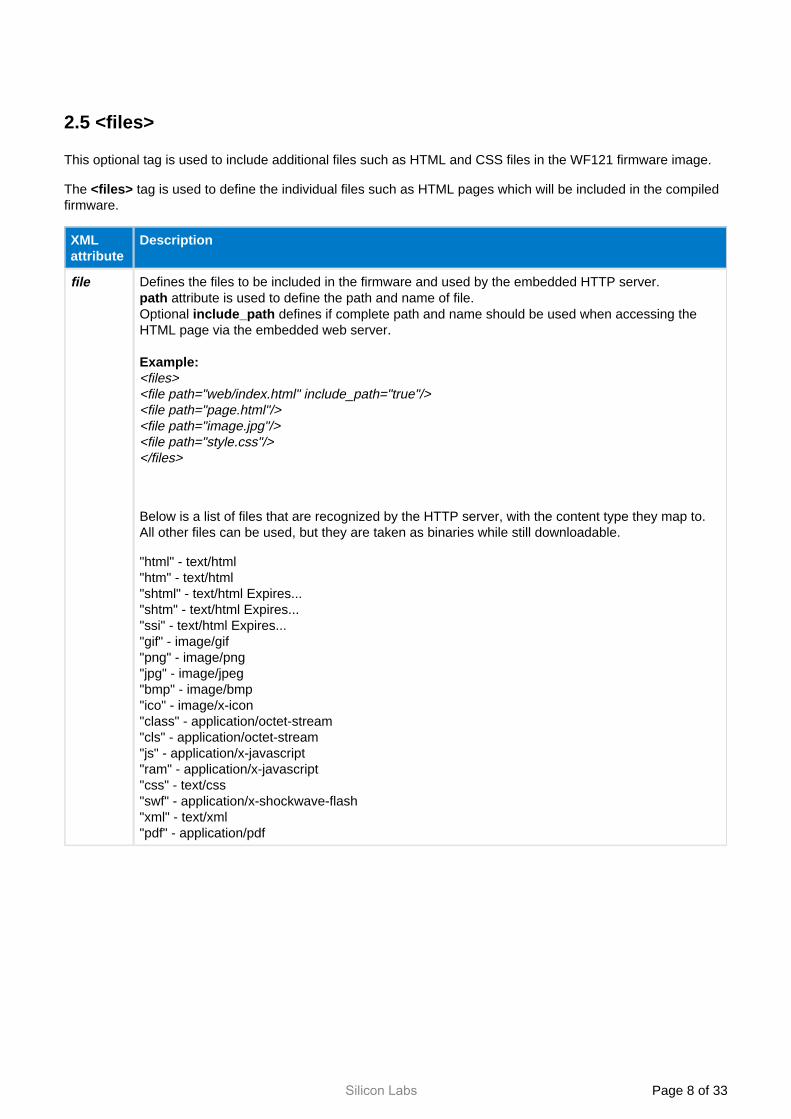
2.5 <files>
This optional tag is used to include additional files such as HTML and CSS files in the WF121 firmware image.
The tag is used to define the individual files such as HTML pages which will be included in the compiled <files>firmware.
XML attribute
Description
file Defines the files to be included in the firmware and used by the embedded HTTP server. attribute is used to define the path and name of file.path
Optional defines if complete path and name should be used when accessing the include_pathHTML page via the embedded web server.
Example:<files><file path="web/index.html" include_path="true"/><file path="page.html"/><file path="image.jpg"/><file path="style.css"/></files>
Below is a list of files that are recognized by the HTTP server, with the content type they map to. All other files can be used, but they are taken as binaries while still downloadable.
"html" - text/html"htm" - text/html"shtml" - text/html Expires..."shtm" - text/html Expires..."ssi" - text/html Expires..."gif" - image/gif"png" - image/png"jpg" - image/jpeg"bmp" - image/bmp"ico" - image/x-icon"class" - application/octet-stream"cls" - application/octet-stream"js" - application/x-javascript"ram" - application/x-javascript"css" - text/css"swf" - application/x-shockwave-flash"xml" - text/xml"pdf" - application/pdf
Silicon Labs Page of 9 33
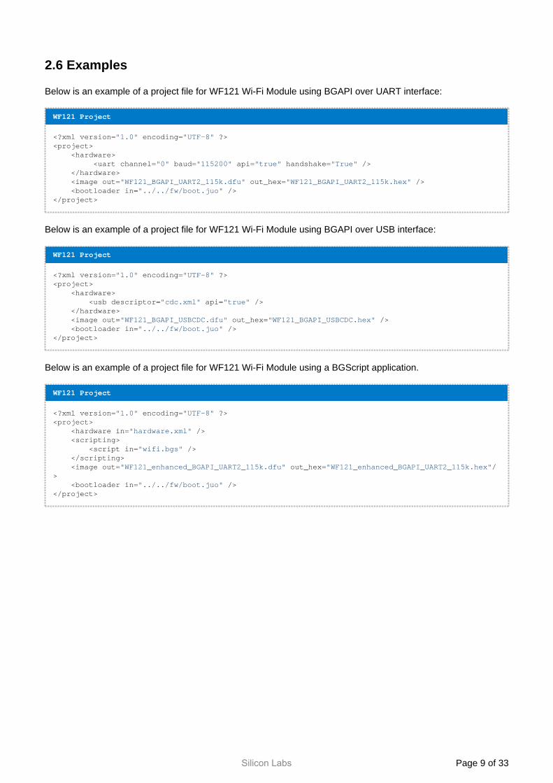
2.6 Examples
Below is an example of a project file for WF121 Wi-Fi Module using BGAPI over UART interface:
WF121 Project
<?xml version="1.0" encoding="UTF-8" ?><project> <hardware>
<uart channel="0" baud="115200" api="true" handshake="True" /> </hardware> <image out="WF121_BGAPI_UART2_115k.dfu" out_hex="WF121_BGAPI_UART2_115k.hex" /> <bootloader in="../../fw/boot.juo" /></project>
Below is an example of a project file for WF121 Wi-Fi Module using BGAPI over USB interface:
WF121 Project
<?xml version="1.0" encoding="UTF-8" ?><project> <hardware>
<usb descriptor="cdc.xml" api="true" /> </hardware> <image out="WF121_BGAPI_USBCDC.dfu" out_hex="WF121_BGAPI_USBCDC.hex" /> <bootloader in="../../fw/boot.juo" /></project>
Below is an example of a project file for WF121 Wi-Fi Module using a BGScript application.
WF121 Project
<?xml version="1.0" encoding="UTF-8" ?><project> <hardware in="hardware.xml" /> <scripting>
<script in="wifi.bgs" /> </scripting> <image out="WF121_enhanced_BGAPI_UART2_115k.dfu" out_hex="WF121_enhanced_BGAPI_UART2_115k.hex"/> <bootloader in="../../fw/boot.juo" /></project>
Silicon Labs Page of 10 33
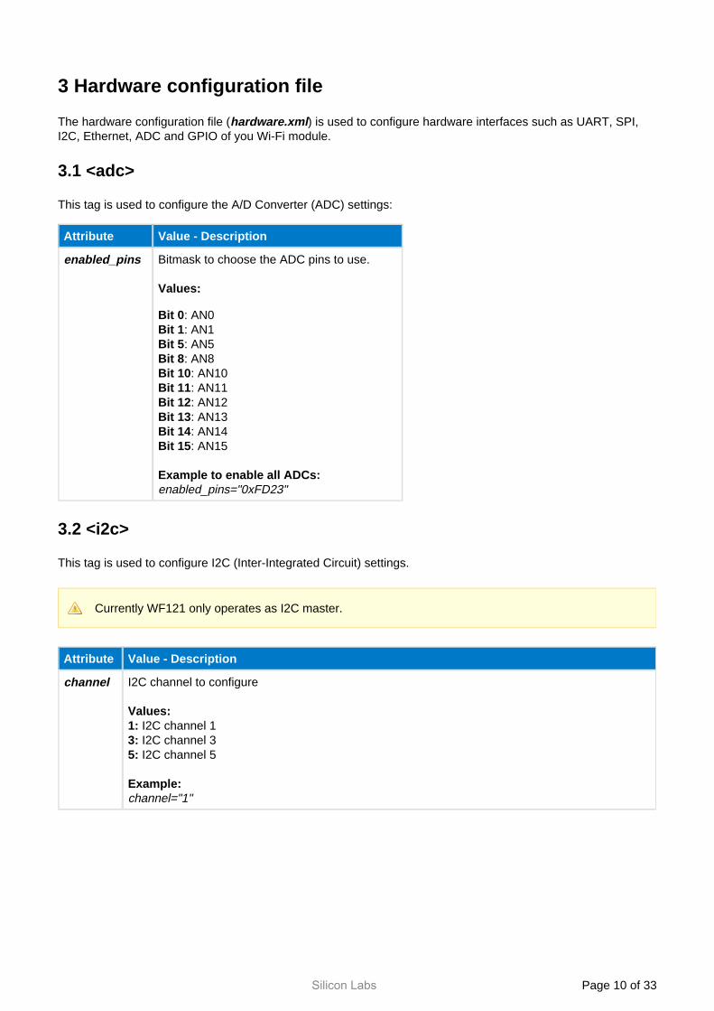
3 Hardware configuration file
The hardware configuration file ( ) is used to configure hardware interfaces such as UART, SPI, hardware.xmlI2C, Ethernet, ADC and GPIO of you Wi-Fi module.
3.1 <adc>
This tag is used to configure the A/D Converter (ADC) settings:
Attribute Value - Description
enabled_pins Bitmask to choose the ADC pins to use.
Values:
Bit 0: AN0: AN1Bit 1: AN5Bit 5: AN8Bit 8: AN10Bit 10: AN11Bit 11: AN12Bit 12: AN13Bit 13: AN14Bit 14: AN15Bit 15
Example to enable all ADCs:enabled_pins="0xFD23"
3.2 <i2c>
This tag is used to configure I2C (Inter-Integrated Circuit) settings.
Currently WF121 only operates as I2C master.
Attribute Value - Description
channel I2C channel to configure
Values: I2C channel 11: I2C channel 33: I2C channel 55:
Example:channel="1"
Silicon Labs Page of 11 33
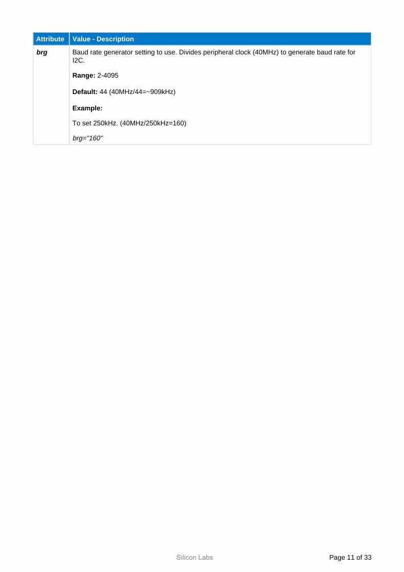
Attribute Value - Description
brg Baud rate generator setting to use. Divides peripheral clock (40MHz) to generate baud rate for I2C.
Range: 2-4095
44 (40MHz/44=~909kHz)Default:
Example:
To set 250kHz. (40MHz/250kHz=160)
brg="160"
Silicon Labs Page of 12 33
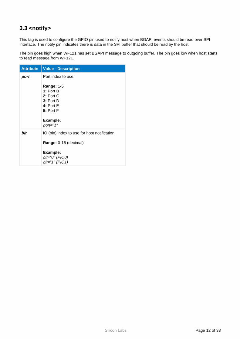
3.3 <notify>
This tag is used to configure the GPIO pin used to notify host when BGAPI events should be read over SPI interface. The notify pin indicates there is data in the SPI buffer that should be read by the host.
The pin goes high when WF121 has set BGAPI message to outgoing buffer. The pin goes low when host starts to read message from WF121.
Attribute Value - Description
port Port index to use.
1-5Range: Port B1: Port C2: Port D3: Port E4: Port F5:
Example:port="1"
bit IO (pin) index to use for host notification
0-16 (decimal)Range:
Example:bit="0" (PIO0)bit="1" (PIO1)
Silicon Labs Page of 13 33
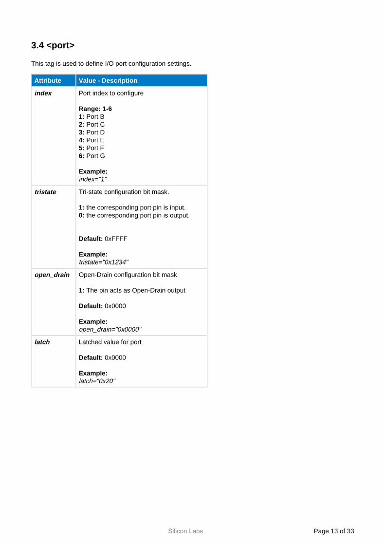
3.4 <port>
This tag is used to define I/O port configuration settings.
Attribute Value - Description
index Port index to configure
Range: 1-6 Port B1: Port C2: Port D3: Port E4: Port F5: Port G6:
Example:index="1"
tristate Tri-state configuration bit mask.
the corresponding port pin is input.1: the corresponding port pin is output.0:
0xFFFFDefault:
Example:tristate="0x1234"
open_drain Open-Drain configuration bit mask
The pin acts as Open-Drain output1:
0x0000Default:
Example:open_drain="0x0000"
latch Latched value for port
0x0000Default:
Example:latch="0x20"
Silicon Labs Page of 14 33
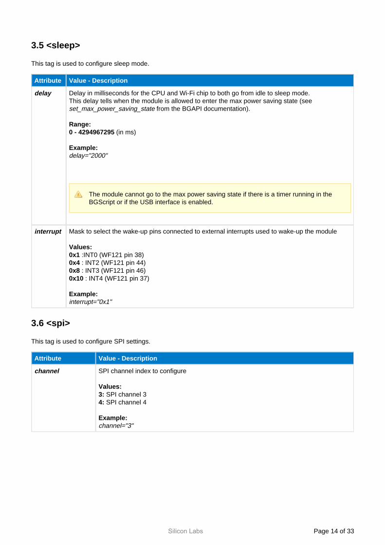
3.5 <sleep>
This tag is used to configure sleep mode.
Attribute Value - Description
delay Delay in milliseconds for the CPU and Wi-Fi chip to both go from idle to sleep mode.This delay tells when the module is allowed to enter the max power saving state (see
from the BGAPI documentation).set_max_power_saving_state
Range:(in ms)0 - 4294967295
Example:delay="2000"
The module cannot go to the max power saving state if there is a timer running in the BGScript or if the USB interface is enabled.
interrupt Mask to select the wake-up pins connected to external interrupts used to wake-up the module
Values: :INT0 (WF121 pin 38)0x1 : INT2 (WF121 pin 44)0x4 : INT3 (WF121 pin 46)0x8 : INT4 (WF121 pin 37)0x10
Example:interrupt="0x1"
3.6 <spi>
This tag is used to configure SPI settings.
Attribute Value - Description
channel SPI channel index to configure
Values: SPI channel 33: SPI channel 44:
Example:channel="3"
Silicon Labs Page of 15 33
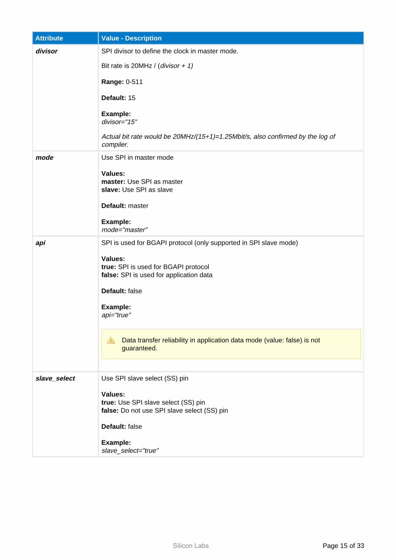
Attribute Value - Description
divisor SPI divisor to define the clock in master mode.
Bit rate is 20MHz / (divisor + 1)
0-511Range:
15Default:
Example:divisor="15"
Actual bit rate would be 20MHz/(15+1)=1.25Mbit/s, also confirmed by the log of compiler.
mode Use SPI in master mode
Values: Use SPI as mastermaster:
Use SPI as slaveslave:
masterDefault:
Example:mode="master"
api SPI is used for BGAPI protocol (only supported in SPI slave mode)
Values: SPI is used for BGAPI protocoltrue: SPI is used for application datafalse:
falseDefault:
Example: api="true"
Data transfer reliability in application data mode (value: false) is not guaranteed.
slave_select Use SPI slave select (SS) pin
Values: Use SPI slave select (SS) pintrue: Do not use SPI slave select (SS) pinfalse:
falseDefault:
Example:slave_select="true"
Silicon Labs Page of 16 33
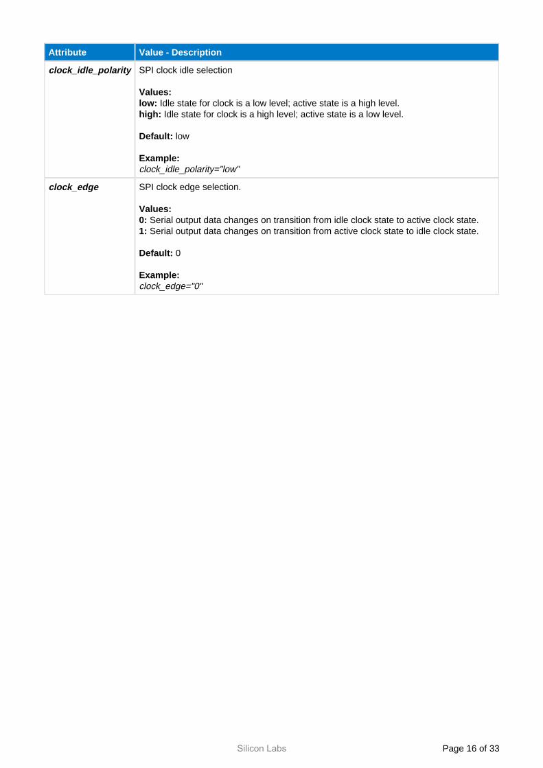
Attribute Value - Description
clock_idle_polarity SPI clock idle selection
Values: Idle state for clock is a low level; active state is a high level.low: Idle state for clock is a high level; active state is a low level.high:
lowDefault:
Example:clock_idle_polarity="low"
clock_edge SPI clock edge selection.
Values: Serial output data changes on transition from idle clock state to active clock state.0: Serial output data changes on transition from active clock state to idle clock state.1:
0Default:
Example:clock_edge="0"
Silicon Labs Page of 17 33
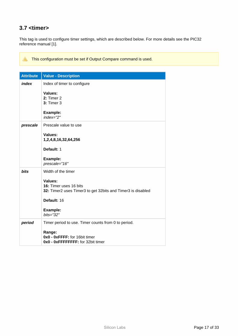
3.7 <timer>
This tag is used to configure timer settings, which are described below. For more details see the PIC32 reference manual [1].
This configuration must be set if Output Compare command is used.
Attribute Value - Description
index Index of timer to configure
Values: Timer 22: Timer 33:
Example:index="2"
prescale Prescale value to use
Values:1,2,4,8,16,32,64,256
1Default:
Example:prescale="16"
bits Width of the timer
Values: Timer uses 16 bits16: Timer2 uses Timer3 to get 32bits and Timer3 is disabled32:
16Default:
Example:bits="32"
period Timer period to use. Timer counts from 0 to period.
Range: for 16bit timer0x0 - 0xFFFF:
for 32bit timer0x0 - 0xFFFFFFFF:
Silicon Labs Page of 18 33
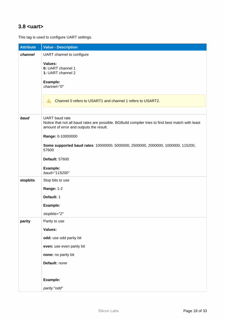
3.8 <uart>
This tag is used to configure UART settings.
Attribute Value - Description
channel UART channel to configure
Values: UART channel 10: UART channel 21:
Example:channel="0"
Channel 0 refers to USART1 and channel 1 refers to USART2.
baud UART baud rateNotice that not all baud rates are possible. BGBuild compiler tries to find best match with least amount of error and outputs the result.
0-10000000Range:
: 10000000, 5000000, 2500000, 2000000, 1000000, 115200, Some supported baud rates57600
57600Default:
Example:baud="115200"
stopbits Stop bits to use
Range: 1-2
Default: 1
Example:
stopbits="2"
parity Parity to use
Values:
odd: use odd parity bit
even: use even parity bit
none: no parity bit
Default: none
Example:
parity:"odd"
Silicon Labs Page of 19 33
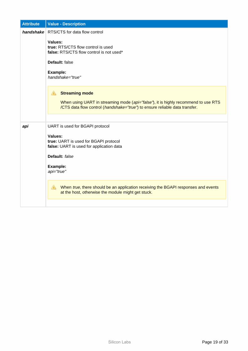
Attribute Value - Description
handshake RTS/CTS for data flow control
Values: RTS/CTS flow control is usedtrue: RTS/CTS flow control is not used*false:
falseDefault:
Example:handshake="true"
Streaming mode
When using UART in streaming mode ( ), it is highly recommend to use RTSapi="false"/CTS data flow control ( ) to ensure reliable data transfer. handshake="true"
api UART is used for BGAPI protocol
Values: UART is used for BGAPI protocoltrue: UART is used for application datafalse:
Default: false
Example:api="true"
When , there should be an application receiving the BGAPI responses and events trueat the host, otherwise the module might get stuck.
Silicon Labs Page of 20 33
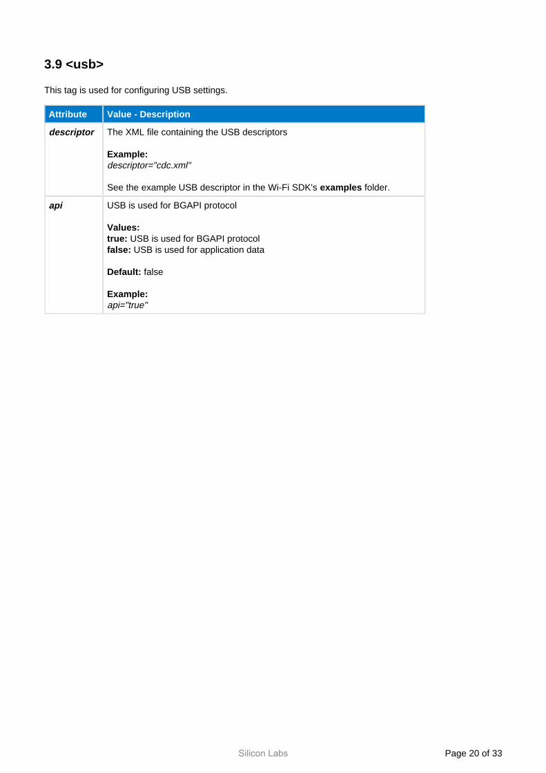
3.9 <usb>
This tag is used for configuring USB settings.
Attribute Value - Description
descriptor The XML file containing the USB descriptors
Example:descriptor="cdc.xml"
See the example USB descriptor in the Wi-Fi SDK's folder.examples
api USB is used for BGAPI protocol
Values: USB is used for BGAPI protocoltrue: USB is used for application datafalse:
falseDefault:
Example:api="true"

Silicon Labs Page of 21 33
3.10 <ethernet>
This tag is used for configuring Ethernet settings.
Attribute Value - Description
enable Enable/disable Ethernet interface
Values: Ethernet interface enabled1: Ethernet interface disabled0:
0Default:
Example:enable="1"
3.11 <sdhc>
This tag is used for configuring SD/SDHC memory card settings.
SD cards with the following specifications are supported:
SD or microSD cardFAT32 or FAT16 file systemCapacity from 2GB to 32GB
Attribute Value - Description
enable Enable/disable memory card usage
Values: memory card in use1: memory card not in use0:
0Default:
Example:enable="1"
spi_port SPI channel where memory card is connected
Values:
3: SPI channel 3 SPI channel 44:
Default: 3
Example:spi_port="3"
Silicon Labs Page of 22 33
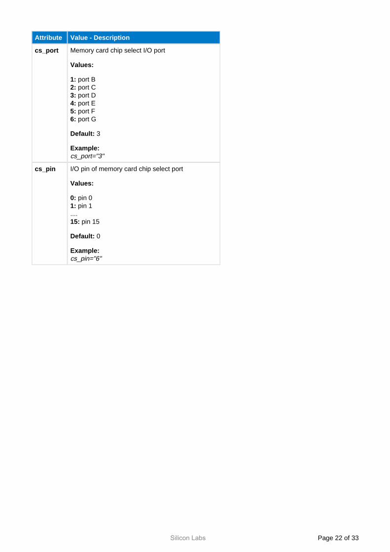
Attribute Value - Description
cs_port Memory card chip select I/O port
Values:
1: port Bport C2: port D3: port E4: port F5: port G6:
Default: 3
Example:cs_port="3"
cs_pin I/O pin of memory card chip select port
Values:
0: pin 0 pin 11:
.... pin 1515:
Default: 0
Example:cs_pin="6"
Silicon Labs Page of 23 33
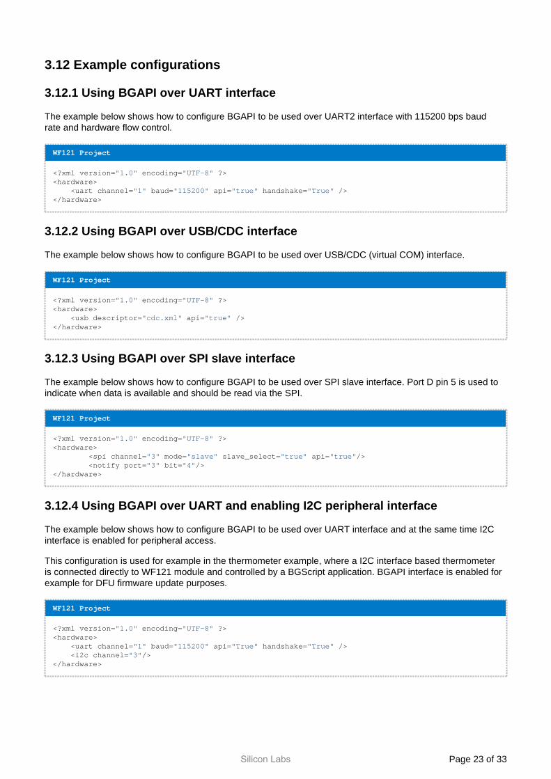
3.12 Example configurations
3.12.1 Using BGAPI over UART interface
The example below shows how to configure BGAPI to be used over UART2 interface with 115200 bps baud rate and hardware flow control.
WF121 Project
<?xml version="1.0" encoding="UTF-8" ?><hardware> <uart channel="1" baud="115200" api="true" handshake="True" /> </hardware>
3.12.2 Using BGAPI over USB/CDC interface
The example below shows how to configure BGAPI to be used over USB/CDC (virtual COM) interface.
WF121 Project
<?xml version="1.0" encoding="UTF-8" ?><hardware> <usb descriptor="cdc.xml" api="true" /></hardware>
3.12.3 Using BGAPI over SPI slave interface
The example below shows how to configure BGAPI to be used over SPI slave interface. Port D pin 5 is used to indicate when data is available and should be read via the SPI.
WF121 Project
<?xml version="1.0" encoding="UTF-8" ?><hardware>
<spi channel="3" mode="slave" slave_select="true" api="true"/> <notify port="3" bit="4"/>
</hardware>
3.12.4 Using BGAPI over UART and enabling I2C peripheral interface
The example below shows how to configure BGAPI to be used over UART interface and at the same time I2C interface is enabled for peripheral access.
This configuration is used for example in the thermometer example, where a I2C interface based thermometer is connected directly to WF121 module and controlled by a BGScript application. BGAPI interface is enabled for example for DFU firmware update purposes.
WF121 Project
<?xml version="1.0" encoding="UTF-8" ?><hardware> <uart channel="1" baud="115200" api="True" handshake="True" /> <i2c channel="3"/></hardware>
Silicon Labs Page of 24 33
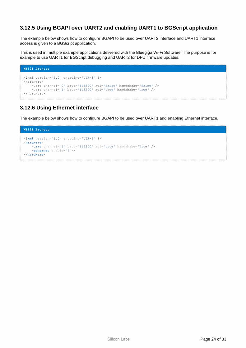
3.12.5 Using BGAPI over UART2 and enabling UART1 to BGScript application
The example below shows how to configure BGAPI to be used over UART2 interface and UART1 interface access is given to a BGScript application.
This is used in multiple example applications delivered with the Bluegiga Wi-Fi Software. The purpose is for example to use UART1 for BGScript debugging and UART2 for DFU firmware updates.
WF121 Project
<?xml version="1.0" encoding="UTF-8" ?><hardware> <uart channel="0" baud="115200" api="false" handshake="false" /> <uart channel="1" baud="115200" api="True" handshake="True" /></hardware>
3.12.6 Using Ethernet interface
The example below shows how to configure BGAPI to be used over UART1 and enabling Ethernet interface.
WF121 Project
<?xml version="1.0" encoding="UTF-8" ?><hardware> <uart channel="1" baud="115200" api="true" handshake="True" /> <ethernet enable="1"/></hardware>
Silicon Labs Page of 25 33
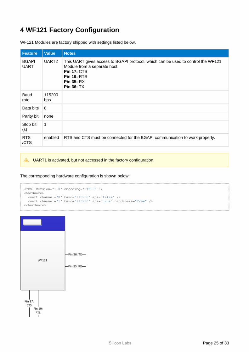
4 WF121 Factory Configuration
WF121 Modules are factory shipped with settings listed below.
Feature Value Notes
BGAPI UART
UART2 This UART gives access to BGAPI protocol, which can be used to control the WF121 Module from a separate host.
CTSPin 17: RTSPin 19: RXPin 35: TXPin 36:
Baud rate
115200 bps
Data bits 8
Parity bit none
Stop bit(s)
1
RTS/CTS
enabled RTS and CTS must be connected for the BGAPI communication to work properly.
UART1 is activated, but not accessed in the factory configuration.
The corresponding hardware configuration is shown below:
<?xml version="1.0" encoding="UTF-8" ?><hardware> <uart channel="0" baud="115200" api="false" /> <uart channel="1" baud="115200" api="true" handshake="True" /> </hardware>

Silicon Labs Page of 26 33
The example project named " " in the SDK's folder matches the default factory wf121 exampleconfiguration.
Silicon Labs Page of 27 33
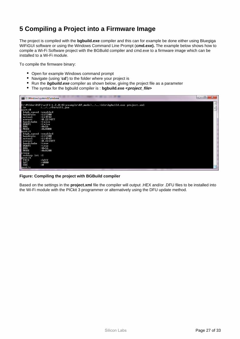
5 Compiling a Project into a Firmware Image
The project is compiled with the compiler and this can for example be done either using Bluegiga bgbuild.exeWiFiGUI software or using the Windows Command Line Prompt ( The example below shows how to cmd.exe).compile a Wi-Fi Software project with the BGBuild compiler and cmd.exe to a firmware image which can be installed to a Wi-Fi module.
To compile the firmware binary:
Open for example Windows command promptNavigate (using ' ') to the folder where your project iscdRun the compiler as shown below, giving the project file as a parameterbgbuild.exeThe syntax for the bgbuild compiler is : bgbuild.exe <project_file>
Figure: Compiling the project with BGBuild compiler
Based on the settings in the file the compiler will output .HEX and/or .DFU files to be installed into project.xmlthe Wi-Fi module with the PICkit 3 programmer or alternatively using the DFU update method.
Silicon Labs Page of 28 33
The BGBuild compiler will output the following information.
Feature Output Explanation
uart:0 high_speed :enabledbaudrate :115200actual :114942error% :0.223497handshake :falseBGAPI :falseBRG :0x56MODE :0x8008
This shows UART1 interface is enabled at 115200 bps baud rate.RTS/CTS handshaking is disabled.BGAPI protocol for this UART is disabled.
The endpoint is allocated with ID 0 (shown in ) and this ID can be uart:0used by the BGScript application or BGAPI commands to send data to it or to route for example UART endpoint to TCP endpoint.
uart:1 high_speed :enabledbaudrate :5000000actual :5000000error% :0handshake :trueBGAPI :trueBRG :0x1MODE :0x8008
This shows UART2 interface is enabled at 5000000 bps baud rate.RTS/CTS handshaking is enabled.BGAPI protocol for this UART is enabled.
sleep wakeup int :1 This message tells interrupt INT0 is enabled (pin 38).
port:N TRIS :ffffLAT :0ODC :0
Shows the default configuration for Port N (B to G) and the setting for tri-state configuration bit mask,open drain configuration, and latched value for the port
script compiler :c:/WiFi/wifi-1.2.0-42/wifi/bin/script_compiler.exescript :APMode.bgsapi :../../api/wifiapi.xmlstack :512
Shows the directory where the bgbuild compiler is located.Shows the BGScript source code file.
Stack size
SW : 359044HW :130USB :0Script:163Free :152661/512000(30%)
SW shows the flash usage (in B) of the firmware image. shows the size of the hardware configuration.HW shows the size of the USB interface descriptor.USB
shows the size of BGScript code.Script shows the total size of the software and how much flash space is left Free
in the device.
Silicon Labs Page of 29 33
6 Installing the Firmware
The firmware can be installed either using the DFU protocol over UART or USB or via the debug interface using the Microchip r and software or PICkit 3 In-Circuit Debugger/Programme PICkit3 Integrated Programming
software from Microchip.Environment (IPE)
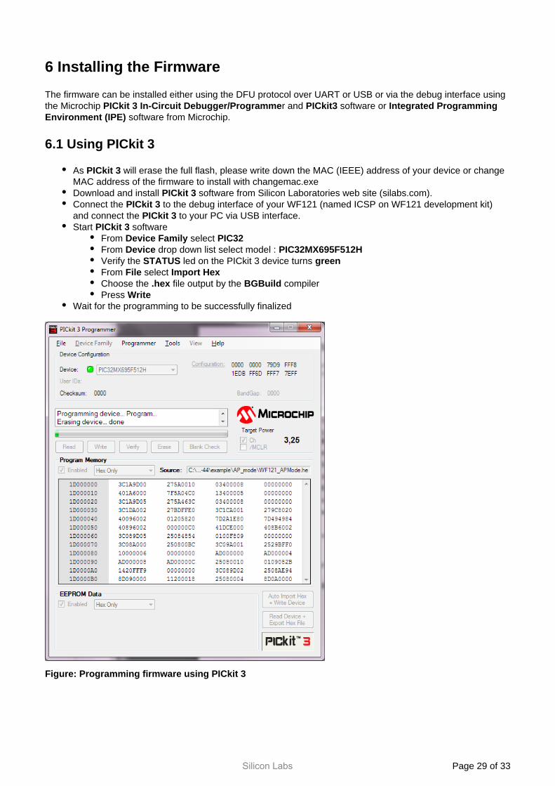
6.1 Using PICkit 3
As will erase the full flash, please write down the MAC (IEEE) address of your device or change PICkit 3MAC address of the firmware to install with changemac.exeDownload and install software from Silicon Laboratories web site (silabs.com).PICkit 3Connect the to the debug interface of your WF121 (named ICSP on WF121 development kit) PICkit 3and connect the to your PC via USB interface.PICkit 3Start softwarePICkit 3
From select Device Family PIC32From drop down list select model : Device PIC32MX695F512HVerify the led on the PICkit 3 device turns STATUS greenFrom select File Import HexChoose the file output by the compiler.hex BGBuildPress Write
Wait for the programming to be successfully finalized
Figure: Programming firmware using PICkit 3
Silicon Labs Page of 30 33
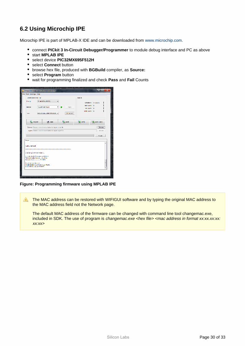
6.2 Using Microchip IPE
Microchip IPE is part of MPLAB-X IDE and can be downloaded from www.microchip.com.
connect to module debug interface and PC as above PICkit 3 In-Circuit Debugger/Programmer start MPLAB IPEselect device PIC32MX695F512Hselect buttonConnectbrowse hex file, produced with compiler, as BGBuild Source:select buttonProgramwait for programming finalized and check and CountsPass Fail
Figure: Programming firmware using MPLAB IPE
The MAC address can be restored with WIFIGUI software and by typing the original MAC address to the MAC address field not the Network page.
The default MAC address of the firmware can be changed with command line tool changemac.exe, included in SDK. The use of program is changemac.exe <hex file> <mac address in format xx:xx.xx:xx:xx:xx>
Silicon Labs Page of 31 33
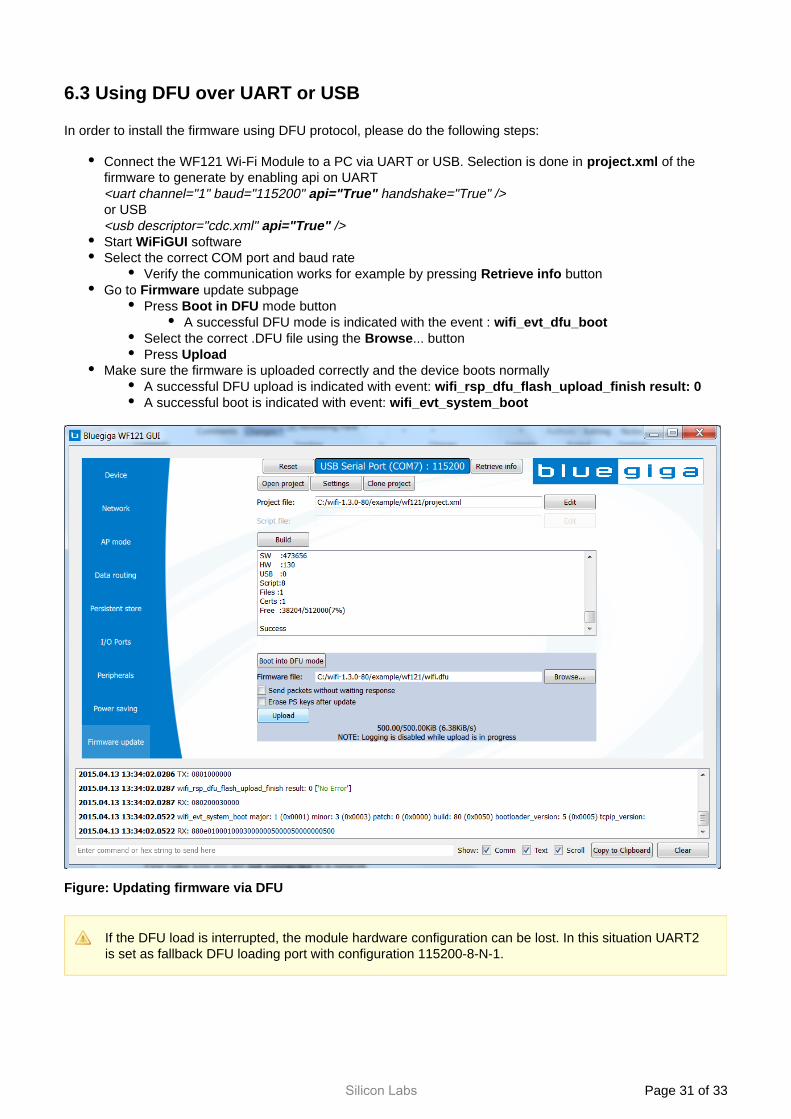
6.3 Using DFU over UART or USB
In order to install the firmware using DFU protocol, please do the following steps:
Connect the WF121 Wi-Fi Module to a PC via UART or USB. Selection is done in of the project.xmlfirmware to generate by enabling api on UART<uart channel="1" baud="115200" handshake="True" />api="True"or USB<usb descriptor="cdc.xml" />api="True"Start softwareWiFiGUISelect the correct COM port and baud rate
Verify the communication works for example by pressing buttonRetrieve infoGo to update subpageFirmware
Press mode buttonBoot in DFUA successful DFU mode is indicated with the event : wifi_evt_dfu_boot
Select the correct .DFU file using the ... buttonBrowsePress Upload
Make sure the firmware is uploaded correctly and the device boots normallyA successful DFU upload is indicated with event: wifi_rsp_dfu_flash_upload_finish result: 0A successful boot is indicated with event: wifi_evt_system_boot
Figure: Updating firmware via DFU
If the DFU load is interrupted, the module hardware configuration can be lost. In this situation UART2 is set as fallback DFU loading port with configuration 115200-8-N-1.

Silicon Labs Page of 32 33
7 References
[1] PIC32 (PIC32MX695F512H) Reference Manual, see Microchip website ( )www.microchip.com

http://www.silabs.com
Silicon Laboratories Inc.400 West Cesar ChavezAustin, TX 78701USA
Smart. Connected. Energy-Friendly.
Productswww.silabs.com/products
Qualitywww.silabs.com/quality
Support and Communitycommunity.silabs.com
DisclaimerSilicon Labs intends to provide customers with the latest, accurate, and in-depth documentation of all peripherals and modules available for system and software implementers using or intending to use the Silicon Labs products. Characterization data, available modules and peripherals, memory sizes and memory addresses refer to each specific device, and "Typical" parameters provided can and do vary in different applications. Application examples described herein are for illustrative purposes only. Silicon Labs reserves the right to make changes without further notice and limitation to product information, specifications, and descriptions herein, and does not give warranties as to the accuracy or completeness of the included information. Silicon Labs shall have no liability for the consequences of use of the information supplied herein. This document does not imply or express copyright licenses granted hereunder to design or fabricate any integrated circuits. The products are not designed or authorized to be used within any Life Support System without the specific written consent of Silicon Labs. A "Life Support System" is any product or system intended to support or sustain life and/or health, which, if it fails, can be reasonably expected to result in significant personal injury or death. Silicon Labs products are not designed or authorized for military applications. Silicon Labs products shall under no circumstances be used in weapons of mass destruction including (but not limited to) nuclear, biological or chemical weapons, or missiles capable of delivering such weapons.
Trademark InformationSilicon Laboratories Inc.® , Silicon Laboratories®, Silicon Labs®, SiLabs® and the Silicon Labs logo®, Bluegiga®, Bluegiga Logo®, Clockbuilder®, CMEMS®, DSPLL®, EFM®, EFM32®, EFR, Ember®, Energy Micro, Energy Micro logo and combinations thereof, "the world’s most energy friendly microcontrollers", Ember®, EZLink®, EZRadio®, EZRadioPRO®, Gecko®, ISOmodem®, Precision32®, ProSLIC®, Simplicity Studio®, SiPHY®, Telegesis, the Telegesis Logo®, USBXpress® and others are trademarks or registered trademarks of Silicon Labs. ARM, CORTEX, Cortex-M3 and THUMB are trademarks or registered trademarks of ARM Holdings. Keil is a registered trademark of ARM Limited. All other products or brand names mentioned herein are trademarks of their respective holders.