Embed Size (px)
Citation preview
National Institute of Technology, Rourkela
Department of Electronics and Communication Engineering
May-2013
WIRELESS ALARM SYSTEM
USING AVR MICROCONTROLLER
Submitted by
Nivedita Sethy
(109EI0344)
WIRELESS ALARM SYSTEM USING
AVR MICRONTROLLER
Thesis submitted in
May 2013
To the department of
Electronics and Communication engineering
of
National Institute of Technology, Rourkela
in partial fulfilment of the requirements for the degree of
Bachelor of Technology
in
Electronics and Instrumentation Engineering
By
Nivedita Sethy
109EI0344
Under the guidance of
Prof. N. Islam
Department of Electronics and Communication Engineering
National Institute of Technology, Rourkela
Rourkela-769008, Odisha, India
CERTIFICATE
This is to certify that the Thesis Report entitled WIRELESS ALARM SYSTEM
USING AVR MICROCONTROLLER submitted by Nivedita Sethy
(109EI0344) of Electronics and Instrumentation Engineering during May 2013
at National Institute of Technology, Rourkela is an authentic work performed by
her under my supervision and guidance.To the best of my knowledge, the matter
embodied in the thesis has not been submitted to any other University / Institute
for the award of any Degree or Diploma.
Date: Prof. N. Islam
Dept. of Electronics and Communication Engg
National Institute of Technology, Rourkela

Pag
ei
National Institute of Technology, Rourkela
Department of Electronics and Communication Engineering
ACKNOWLEDGEMENT
I wish to express my deep sense of gratitude to Prof. N. Islam, Dept. of Electronics
and Communication Engineering, National Institute of Technology, Rourkela, my
guide, for his consistent encouragement, guidance and support to carry out this
project, and for giving me an opportunity to work on this project and providing me
with a great environment to carry my work in ease.
Nivedita Sethy
109EI0344
Pag
eii
CONTENTS
Certificate
Acknowledgement
List of figures
List of tables
Abstract
Chapter 1 Introduction 1
1.1 Introduction and motivation 2
1.2 Literature review 3
1.3 Objective 4
1.4 Chapter wise distribution of the thesis 5
1.5 Summary 6
Pag
eiii
Chapter 2 Sensor 7
2.1 Introduction 8
2.2 Types of pressure sensors 10
2.4 Force sensor 11
2.5 Conclusion 11
Chapter 3 Force sensitive resistor 12
3.1 Introduction 13
3.2 Testing of FSR 14
3.3 Connection of FSR 14
3.4 Conclusion 15
Pag
eiv
Chapter 4 RF Module 16
4.1 Introduction 17
4.2 Transmitter 17
4.3 Receiver 19
4.4 Conclusion 20
Chapter 5 AVR Microcontroller 21
5.1 Introduction 22
5.2 Features 22
5.3 Hardware and Software 23
5.4 Conclusion 24
Pag
ev
Chapter 6 Output components 25
6.1 Introduction 26
6.2 Buzzer 26
6.3 Servo motor 27
6.4 LED 27
6.5 Conclusion 27
Chapter 7 Hardware Implementation 28
7.1 Introduction 29
7.2 Hardware model 29
7.3 Working 31
7.4 Conclusion 31
Chapter 8 Summary and Conclusion 32
References
Pag
evi
List of figures
Fig no. Title
1.1 Functional block diagram of the system
3.1 Connection of FSR
4.1 RF Transmitter
4.2 RF Receiver
5.1 AVR Trainer board
7.1 RF Module
7.2 Wireless alarm system with servo motor
List of tables
Table no. -2.1 Common transducers
Pag
evii
ABSTRACT
The main aim is to design a wireless alarm system using AVR microcontroller.
This alarm system had a force sensor as its main component. The force sensor senses the force or
pressure and then it create a sound which can make a person to avoid problems. This alarm
system is used for the home security to detect presence of intruders getting into the home. A
servo motor is also installed here this shows the automatic movement of motor which is
implemented for automatic control of the gate. So, we are designing a wireless alarm system
which also acts as an alarm system and also for automatic barrier control. This doesn’t occur at a
time a certain time has been kept by using time delay.

Pag
e1
CHAPTER 1
Introduction
Introduction and motivation
Literature review
Chapter wise organisation of the thesis
Summary
Pag
e2
1.1 Introduction and motivation
In this 21st century almost all the advanced things in the world are made using
electronics as it’s basic component. Though the ideas are old but renewal of the system is
due to the replacement of the base part of the system by an electronics system. This world
is now full of the electronics substances because almost every substance in this world has
atleast a small part of electronics substance. There are many things in this world which is
very special to particular person it can be due to cost or importance. So, we need to
protect that thing from the exposure of bad environment for which we install an alarm
system.
An alarm system is needed to prevent any bad condition or situation which
we don’t want to face. When alarm device is installed then we can avoid unsuitable
circumstances as we can use a fire alarm, antitheft alarm device etc. So we need an alarm
system which can be implemented for antitheft purpose. We will also implement in the
automatic gate control. We will design a wireless alarm system having a feature of
automatic gate control also which can achieved by using a servo motor. The servo motor
will control the barrier or gate which is need to open when a vehicle comes and close it
after a certain time.
Pag
e3
1.2 Literature review
An alarm device or system gives an audible, visual or any other form of
signal during a problem or any unavoidable circumstances. They are often connected
with a buzzer or siren. They have a capability of causing a fight or flight response in
humans. In this condition a person will panic and either flee the perceived danger or
attempt to eliminate it. Intruder alarm systems can be integrated with flood, gas and
smoke detectors to be used for functions such as gas leak, flood and fire detection. And
then it will be possible to call for an ambulance or call the fire station directly with the
panic button in any emergency. In a paper an alarm system has been described.
An alarm device comprises a blocking oscillator circuit composed of a
transformer and a transistor and a sound emitter using a piezoelectric effect exhibiting
element and interposed between one end of the secondary coil connected to the base of
the transistor. When the sound emitter receives a slight vibration, it generates an
electromotive force which is applied to the base of the transistor. Consequently, the
blocking oscillation circuit oscillates and causes the sound emitter to issue an alarm.
As the above paper described and some papers referred it is known that we need
to use a sensor which will sense or detect the condition which is unavoidable and the
alarm gives a sound which make us realise that there is something wrong over here.
After hearing the alarm sound we can take the precautions needed and we can protect
ourselves from the problem.
Pag
e4
1.3 Objective
The objective of my project is to design an wireless alarm system, that will
possess built in buzzer sound facility even if it is outside the home. This will enable a
person to know that he should be alert. The buzzer alerts help him in detecting the
presence of intruders getting into the house even when he will be in deep sleep.
In this wireless system we will also use a servo motor which can be
implemented in automatic control of gate. The wireless system also counts the number
entering into the gate. This servo motor will be handled by using a code and it will
operate automatically.
All of the operations to be done by this system is handled by the software
part in which we write specific code for the specific operations.
Pag
e5
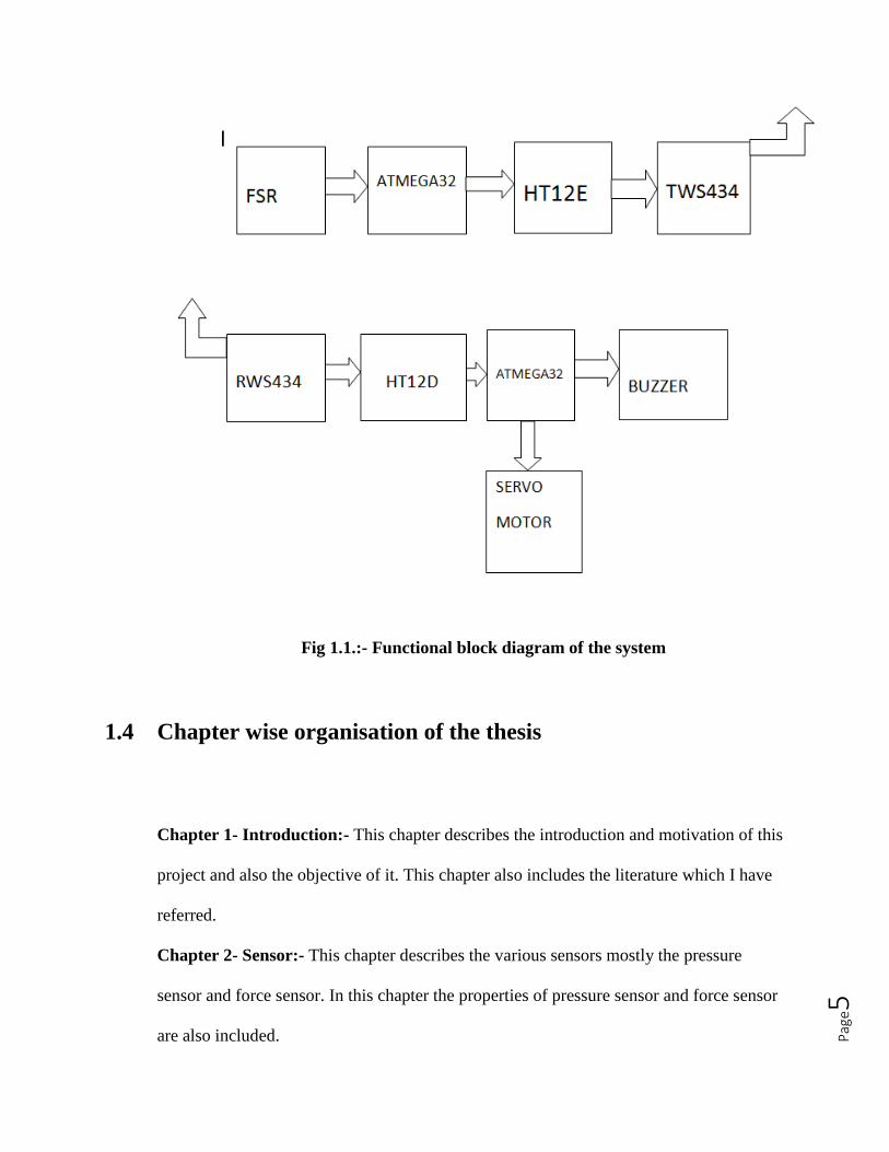
Fig 1.1.:- Functional block diagram of the system
1.4 Chapter wise organisation of the thesis
Chapter 1- Introduction:- This chapter describes the introduction and motivation of this
project and also the objective of it. This chapter also includes the literature which I have
referred.
Chapter 2- Sensor:- This chapter describes the various sensors mostly the pressure
sensor and force sensor. In this chapter the properties of pressure sensor and force sensor
are also included.
Pag
e6
Chapter 3- Force Sensitive Resistor:- This chapter describes the features and the
properties of the force sensitive resistor used in this project.
Chapter 4- RF module:- This chapter describes the components of the RF module. The
properties of the transmitter and receiver are described. The chapter also gives the
information about the connection of the RF module with encoder and decoder.
Chapter 5- AVR Microcontroller:- This chapter describes the features of the AVR
microcontroller. This includes the software part or coding part of the project.
Chapter 6- Output components:- This chapter describes the output components i.e. the
components shows the output –Buzzer and Servo motor.
Chapter 7- Hardware implementation:- This chapter show the hardware part of the
project. This shows the circuit design of the alarm system and the automatic control of
the servo motor.
Chapter 8- Summary and Conclusions:- In this chapter, the final conclusions and
summary of the project is presented.
1.5 Summary
In this introductory chapter, brief description of the alarm system and the wireless
techniques, the motivation towards the hardware implementation rather than the software
solution of the product has been summarized. Literature review of previous papers has
been described. Finally there is summary of chapter wise distribution of the thesis.
Pag
e7
CHAPTER 2
Sensors
Introduction
Types of pressure sensors
Force sensor
Conclusion
Pag
e8
2.1 Introduction
A sensor is a device which receives and responds to a signal when touched or
sensed. When the measured quantity changes this change the output of the sensor the rate
of change is called as the sensitivity of the sensor. Sensor is also called detector because
it detects the signal which is applied. Devices which perform an input function are
commonly called sensors because they sense a physical change in some characteristic that
changes in response to some excitation. Devices which perform an output function and
generally called actuators which are used to control some external device. Both sensors
and actuators are collectively known as transducers because they are used to convert
energy of one kind into energy of other kind.
Pag
e9
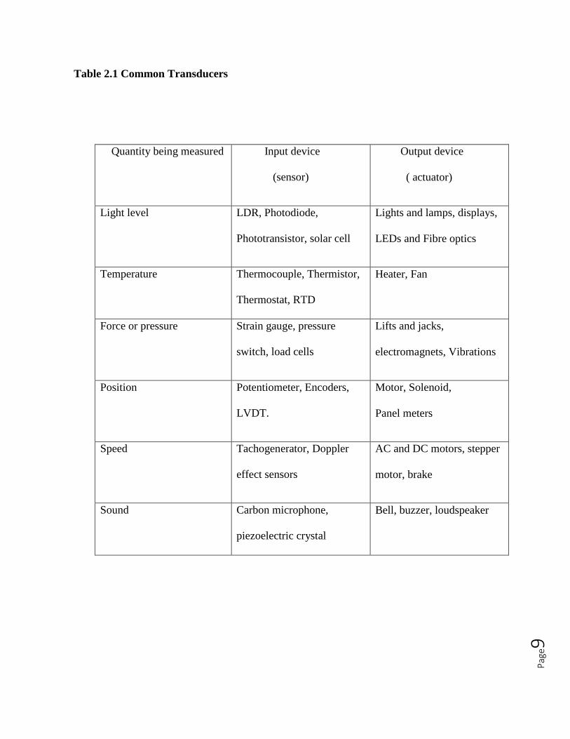
Table 2.1 Common Transducers
Quantity being measured Input device
(sensor)
Output device
( actuator)
Light level LDR, Photodiode,
Phototransistor, solar cell
Lights and lamps, displays,
LEDs and Fibre optics
Temperature Thermocouple, Thermistor,
Thermostat, RTD
Heater, Fan
Force or pressure Strain gauge, pressure
switch, load cells
Lifts and jacks,
electromagnets, Vibrations
Position Potentiometer, Encoders,
LVDT.
Motor, Solenoid,
Panel meters
Speed Tachogenerator, Doppler
effect sensors
AC and DC motors, stepper
motor, brake
Sound Carbon microphone,
piezoelectric crystal
Bell, buzzer, loudspeaker
Pag
e10
2.2 Types of pressure sensors
There are many types of pressure sensors. It is mostly classified on the
basis of type of measurement in does. The pressure sensors also vary due to the
manufacturing material of the sensor. Some of the pressure sensors are briefly described
over here.
Potentiometric pressure sensors use a capsule or bourdon tube to drive a
wiper arm on a resistive element. These have repeatability and hysteresis errors. These
devices are of low cost and are used in low performance applications. Inductive pressure
sensors are based on varying inductance or inductive coupling are used. These all require
AC excitation of the coil. Capacitive pressure sensors typically use a thin diaphragm as
one palate of the capacitor. When pressure is applied the diaphragm deflect and the
capacitance change. Piezoelectric pressure sensor are bi-directional transducers capable
of converting stress into an electric potential and vice versa.
Pag
e11
2.3 Force sensor
The force sensors are the sensors which detects or sends a signal when a force
is applied. It is quite similar to that of pressure sensor. Force sensor is defined as the
sensor which convert the input mechanical force into the output electrical signal. There
are many advanced version of force sensors found nowadays.
2.4 Conclusion
This chapter labels the various types of sensors and give brief idea about the
force sensor and pressure sensor which we are going to use as a base element.
Pag
e12
CHAPTER 3
Force sensing resistor (FSR)
Introduction
Testing of FSR
Connection of FSR
Conclusion
Pag
e13
3.1 Introduction
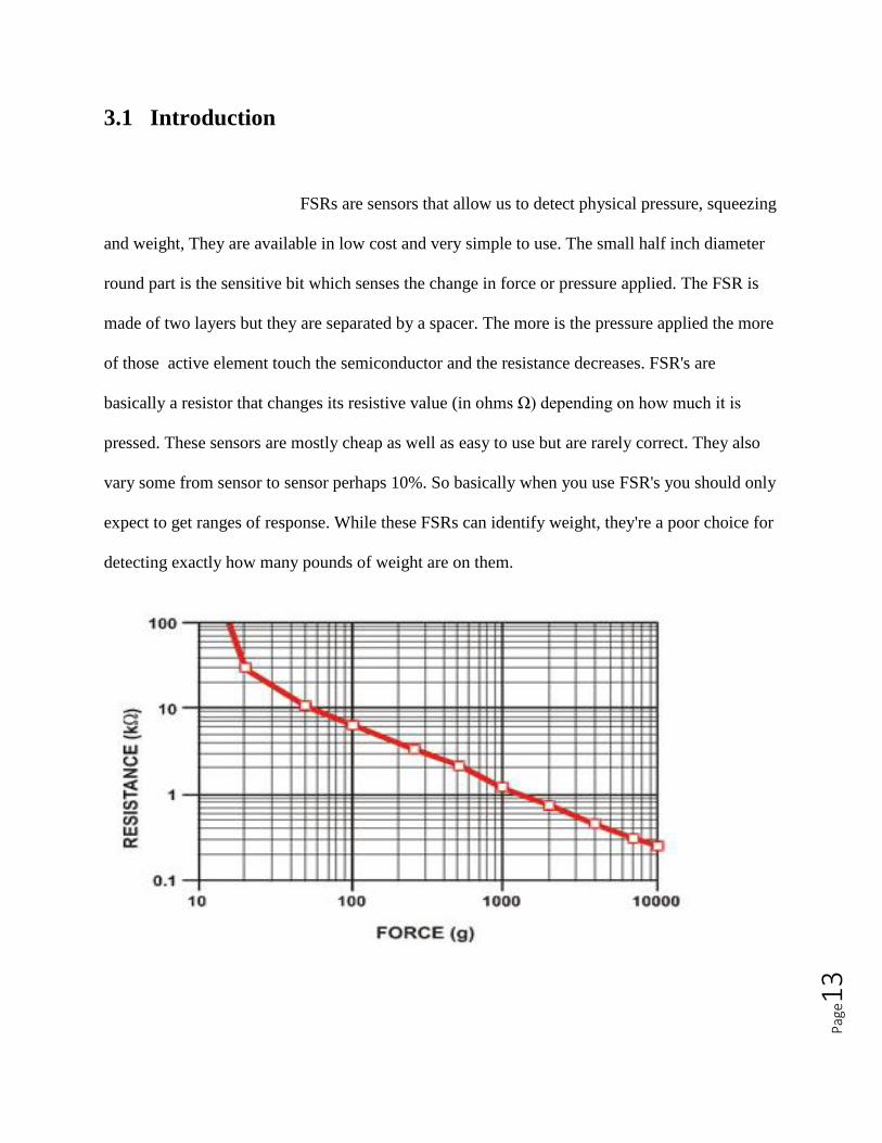
FSRs are sensors that allow us to detect physical pressure, squeezing
and weight, They are available in low cost and very simple to use. The small half inch diameter
round part is the sensitive bit which senses the change in force or pressure applied. The FSR is
made of two layers but they are separated by a spacer. The more is the pressure applied the more
of those active element touch the semiconductor and the resistance decreases. FSR's are
basically a resistor that changes its resistive value (in ohms Ω) depending on how much it is
pressed. These sensors are mostly cheap as well as easy to use but are rarely correct. They also
vary some from sensor to sensor perhaps 10%. So basically when you use FSR's you should only
expect to get ranges of response. While these FSRs can identify weight, they're a poor choice for
detecting exactly how many pounds of weight are on them.
Pag
e14
As previously stated, the FSR's resistance varies with further application
pressure. In absence of pressure, the sensor seems like an infinite resistor i.e. open circuit, with
an increase in pressure, the value of resistance reduces. This graph specifies approximately the
value of resistance of the sensor at different force measurements. It is important to notice that the
graph isn't really linear and that at especially low force measurements it quickly goes from
infinite to 100KΩ.
3.2 Testing of FSR
The simplest way to determine how the FSR works is to connect a multi-meter in
resistance measurement mode to the two tabs on the sensor and see how the resistance varies. As
the resistance changes a lot, an auto-ranging meter works well here. Or else, just make sure to try
different ranges, between 1 Mohm and 100 ohm before 'giving up'.
Resistance range: Infinite/open circuit at no pressure, 100KΩ at light pressure to 200Ω at
maximum pressure.
3.3 Connection of FSR
FSRs are basically resistors so, they are non-polarized. That means we can
connect them up either way and they'll work just fine! FSRs are often a polymer with conductive
material silk-screened on. Which means that they're plastic as well as connection tab is crimped
Pag
e15
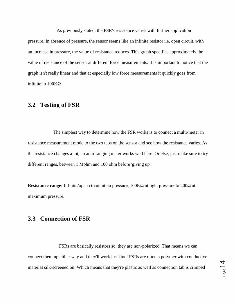
on slightly delicate material. Thus the ideal way to connect to these is to merely plug them into a
breadboard or use a clamp-style connector like alligator clips, or a female header or a terminal
block.
Fig 3.1: connection of FSR
3.4 Conclusion
This chapter describes the features of the force sensing resistor. The testing and
connection is also known.
Pag
e16
CHAPTER 4
RF Module
Introduction
Transmitter connection
Receiver connection
Conclusion
Pag
e17
4.1 Introduction
As we are designing a wireless alarm system we will definitely need a pair of
transmitter and receiver. The transmitter and receiver pair is the basic need for any wireless
device or system. As the name suggests. the RF module operates at Radio Frequency. The
corresponding frequency range varies between 30 kHz & 300 GHz. In this RF system, all the
digital data is characterized as changes in the amplitude of carrier wave. This type of modulation
is referred to as Amplitude Shift Keying (ASK).
Transmission through RF is better than IR (infrared) because of several reasons. First of
all, signals through RF can travel through larger distances making it suitable for long range
applications. Moreover, while IR mostly operates in line-of-sight (LOS) mode, RF signals can
travel even if there is an obstruction between transmitter & receiver. Further, RF transmission is
stronger and more reliable than IR transmission. RF communication uses a particular frequency
unlike IR signals which are affected by other IR emitting sources. This RF module consists of
an RF Transmitter and an RF Receiver.
Pag
e18
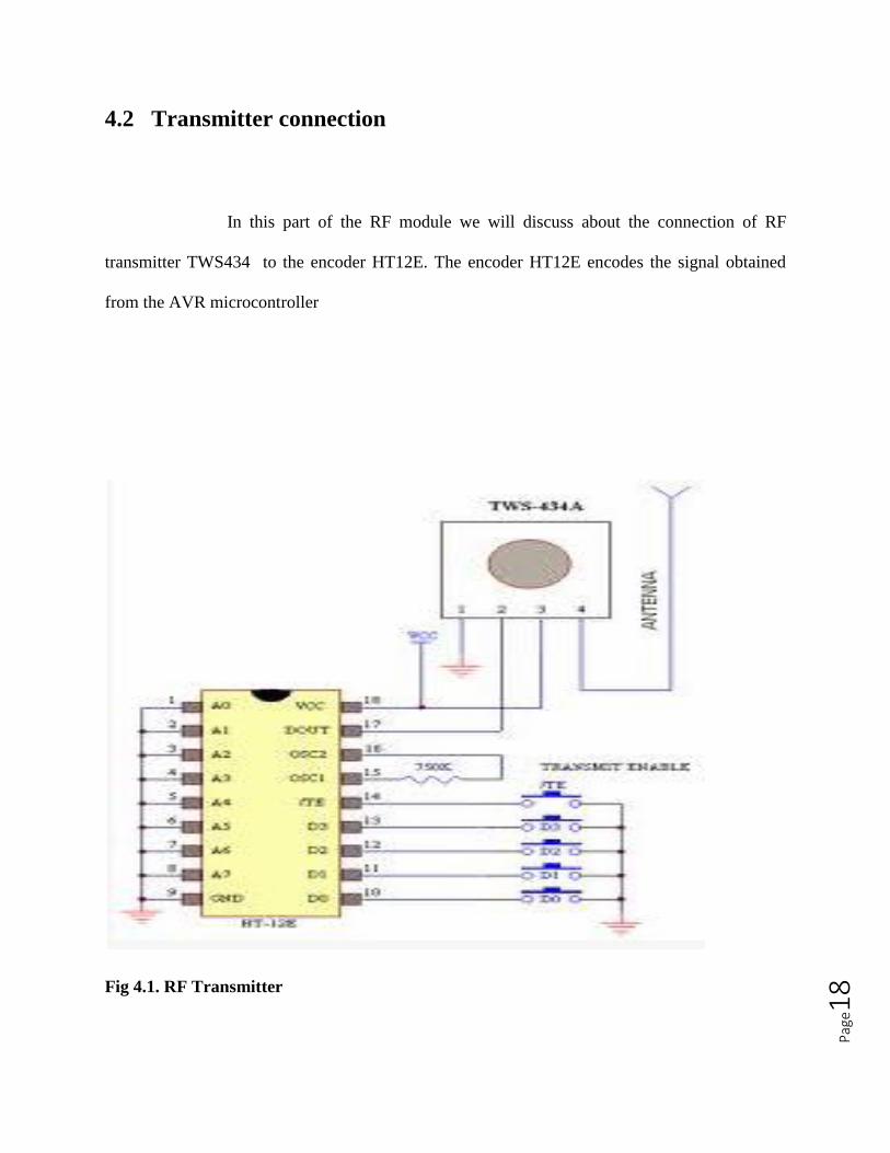
4.2 Transmitter connection
In this part of the RF module we will discuss about the connection of RF
transmitter TWS434 to the encoder HT12E. The encoder HT12E encodes the signal obtained
from the AVR microcontroller
Fig 4.1. RF Transmitter
Pag
e19
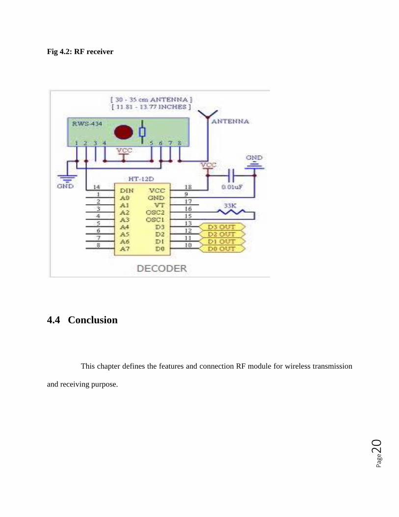
4.3 Receiver connection
In this section the RF receiver is connected to the decoder HT12D. The data we
had received from the RF receiver need to be decoded for further outputs needed. There is a
capacitor connected between the vcc and ground to maintain the voltage difference between
them.
Pag
e20
Fig 4.2: RF receiver
4.4 Conclusion
This chapter defines the features and connection RF module for wireless transmission
and receiving purpose.
Pag
e21
CHAPTER 5
AVR Microcontroller
Introduction
Features
Hardware and software
Conclusion
Pag
e22
5.1 Introduction
The AVR is a modified Havard architecture 8 bit RISC single chip
microcontroller which was developed by Atmel in 1996. The AVR microcontroller was one of
the first microcontroller families to use on chip flash memory for program storage. The AVR is a
modified architecture of Havard machine where program and data are stored in separate physical
memory systems that appear in different address spaces, but have the ability to read the data
items from the program memory using certain instructions.
We are using an AVR trainer Board over here which contains a ATMEGA32 avr
microcontroller. We use a microcontroller because it is programmable, a code typically written
in C decides what it does. It is easier to write a code than design and make a custom circuit for
complex jobs. The same can be used in hundreds of applications.
5.2 Features
High performance, low power 8 bit microcontroller
Advanced RISC architecture
Non-volatile program as well as data memories
Pag
e23
On chip analog comparator
8 channel, 10 bit ADC
32 programmable I/O line
Low power consumption
32Kb of programmable flash memory
5.3 Hardware and Software part
Software used for AVR microcontroller are AVRStudio and Winavr. In this
software part the code is written and the compiled.
Hardware used here is the AVR programmer board and the application board.
In this part we can get output and these can be involved to get some result.
Pag
e24
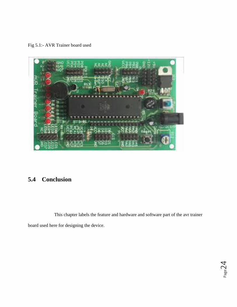
Fig 5.1:- AVR Trainer board used
5.4 Conclusion
This chapter labels the feature and hardware and software part of the avr trainer
board used here for designing the device.
Pag
e25
CHAPTER 6
OUTPUT COMPONENTS
Introduction
Buzzer
Servo motor
LED
Conclusion
Pag
e26
6.1 Introduction
The output components are the components which can be used for
detection of the output. These components help us to know the status of the output. They can be
available in the same AVR trainer board or can be connected externally. The circuit we have
designed or the system we have designed we have three output components. They are buzzer,
servo motor and the LED.
6.2 Buzzer
The buzzer is present in the same AVR trainer board. This buzzer makes sound
when the force is applied to the force sensitive resistor. This acts as an alarm system and it is
connected through the RF module so it can be called as wireless alarm system. When some force
is applied to the force sensitive resistor the signal is transmitted to the receiver and the buzzer
makes sound which serves as an alarm. The alarm blows for 2 sec and then it is off.
Pag
e27
6.3 Servo motor
Servo motor is a rotary actuator that allows for precise control of angular
position. It comprises of a motor coupled to a sensor for position feedback, through a reduction
gearbox. This servo motor is externally connected to the AVR microcontroller to get the output.
When the buzzer is off the servo motor starts rotating and remain open for 5 sec and then it
closes.
6.4 LED
There is a strip of LED present in the AVR trainer board. When this LED
works as a counter and it shows how many times the force is applied to the force sensitive
resistor. When we switch on the reset button the counting starts from the beginning.
6.5 Conclusion
This chapter labels the outputs we get from the components we had connected to
detect the signal and count the output.
Pag
e28
CHAPTER 7
Hardware Implementation
Introduction
Hardware model
Working
Conclusion
Pag
e29
7.1 Introduction
The programs or codes are executed and compiled. These codes are durnped by
using a program burner and it is dumped into the microcontroller. Then the hardware section of
the system does the work. Hardware implementation is the hardware section of the system and
the output we get in that.
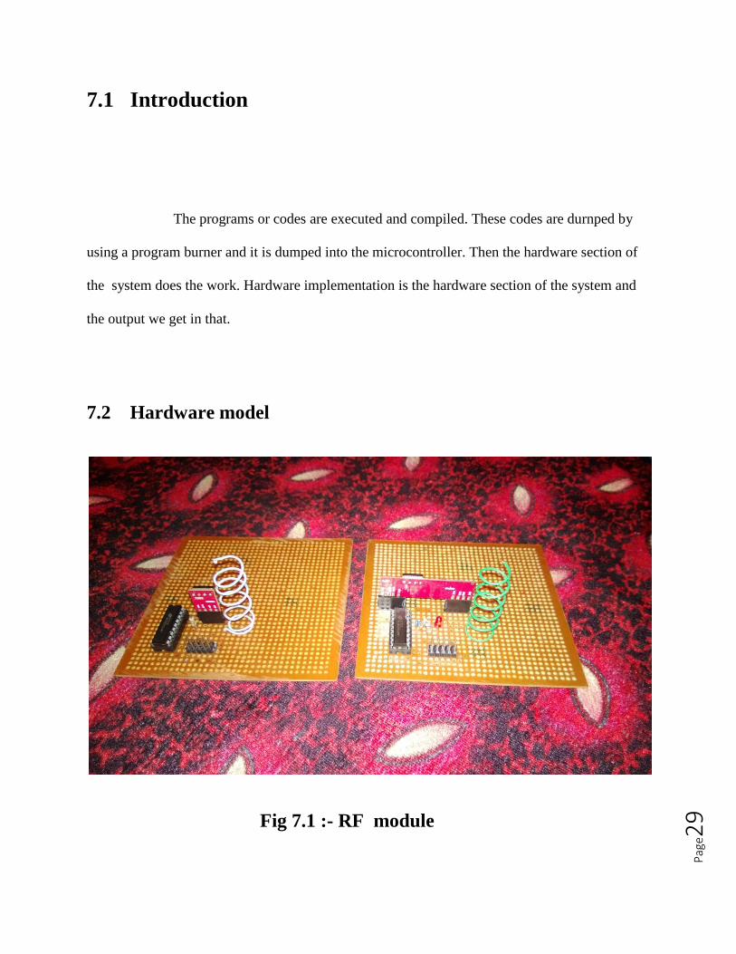
7.2 Hardware model
Fig 7.1 :- RF module
Pag
e30
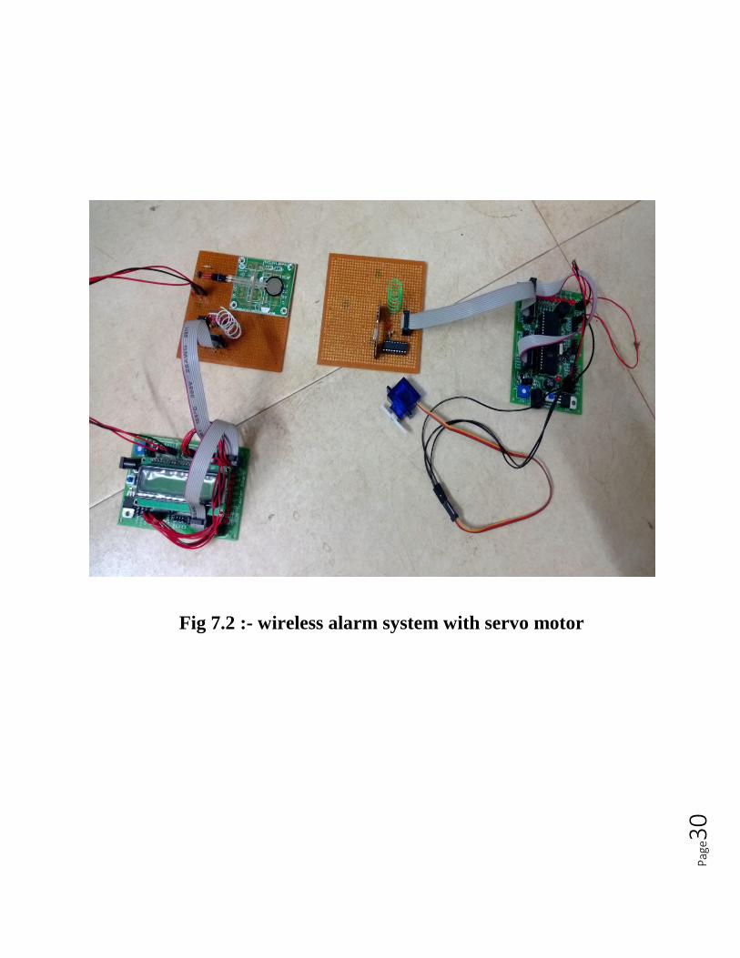
Fig 7.2 :- wireless alarm system with servo motor
Pag
e31
7.3 Working
When a force is applied to the FSR the transmitter will transmit the signal to the
receiver. After receiving a signal the buzzer will start and stop after blowing for 2 sec. Then the
servo motor starts rotating and remain open for 5 sec and then it will close. The LED present
over there counts the number of times FSR has been applied pressure.
7.4 Conclusion
This chapter ss the designed hardware model of the wireless alarm system
using avr microcontroller and the servo motor placed there which can be implemented for
automatic control gate opening and closing.
Pag
e32
CHAPTER 8
Summary and conclusion
In this thesis the wireless alarm system is designed using AVR microcontroller. This
shows the expected output. It includes the operation of servo motor due to the force sensor. By
using this alarm system we can protect our homes from intruders. Even if the owner of the house
is in deep sleep he can know someone is getting into the house through window. The signal from
the window get transmitted to the bedroom and the owner can know. The operation of the servo
motor gives us another application. It will show the automatic control of gate. When any vehicle
comes the gate opens and it remain open for 2 sec and then gate will close. The use of AVR
microcontroller reduces the complexity of the circuit.
Pag
e33
References
http://www.engineersgarage.com/electronic-
components/rf-module-transmitter-receiver
http://learn.adafruit.com/force-sensitive-resistor-
fsr/using-an-fsr
http://extremeelectronics.co.in/rf/rf-communication-
between-microcontrollers-part-i/
www.electronics-tutorials.ws/io

Pag
e34


![Apple ][ Emulation on an AVR Microcontroller](https://img.pdfslide.net/doc/110x75/589edeef1a28abd14a8c06d8/apple-emulation-on-an-avr-microcontroller.jpg)