Embed Size (px)
Citation preview

Synchronous Alternators

2
ContentThe Company
Basic philosophy of the WKV AG 3
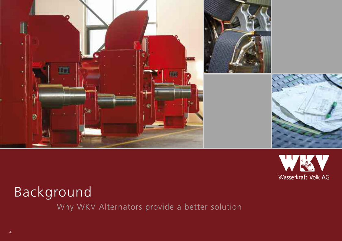
BackgroundWhy WKV Alternators provide a better solution 4
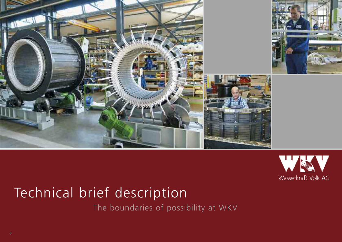
Technical brief descriptionThe boundaries of possibility at WKV 6
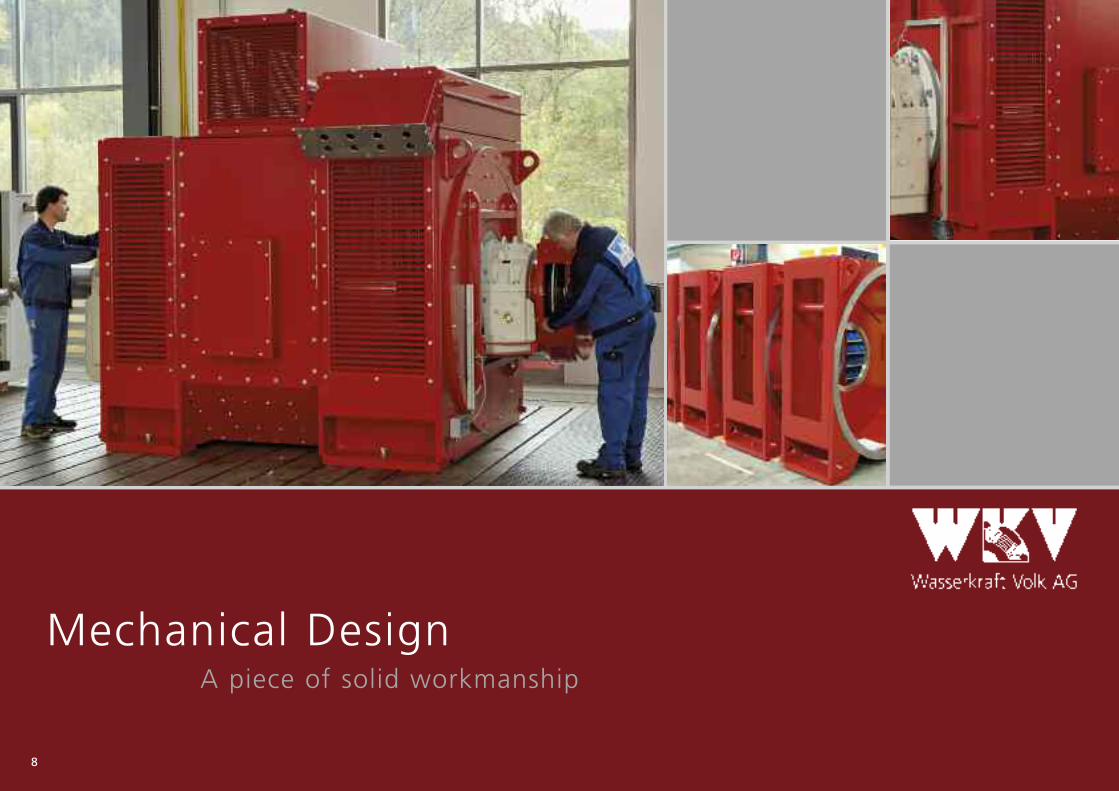
Mechanical Design A piece of solid workmanship 8
Enclosure, cooling, design structureThe optimum solution for every application 12
Electrical behaviourHow does a WKV alternator actually work? 14
Excitation and voltage regulationUsing the world’s best components 16
Operating performanceDetails provided by experts for adepts 18
Insulation and protection devicesNothing lives forever, but we are pretty close 22
Quality assurance, factory testingTrust is good, control is better 24
World-wide after sales serviceIf the worst comes to the worst 26
The head quarter inGutach: The “Tower”
Production plants in Gutach

A sustainable energy policy, based on renewable resources, will be crucial tothe future and for coming generations. Hydropower is one of the front-run-ners among such renewable energies.
As a leading supplier of technology and equipment for small and mediumsized hydropower plants, WKV has decided to make a significant contribu-tion to such a sustainable future.
This basic philosophy is to be found throughout the complete productionrange of the WKV AG:
The entire energy needed for the production process is generated in thein-house hydro power plant,Room heating is done by heat pumps utilizing even the exhaust heat ofthe test field,roof greening and solar collectors have a share in environmentally re-sponsible air conditioning.
As a medium size enterprise, our main focus is only Germany as the loca - tion for factories in view of our social responsibility and obligation towardsthe country and future generations. Last but not least, a great portion ofour success comes from our highly motivated, dedicated, devoted andcommitted work force receiving consistent advance training, education andup-dating in their respective fields in order to render a reliable and persis-tent service to our customers.
We are only caretakers of the
world and its resources that we
pass on to our children.(WKV’s company slogan)
Roof-greening andsolar collectors onthe office buildings
In-house power plant in Gutach
3
The CompanyBasic philosophy of the WKV AG
4
BackgroundWhy WKV Alternators provide a better solution

The basics are unchangeable. The physical laws are permanent.So, it’s vital always to make the best out of them!
A highly skilled and talented team of engineers, designers and techni -cians at WKV AG is marching towards efficient and innovative solutions.Besides optimizing the alternators magnetically and electro-dynamically,our main focus is to provide a perfect fit to the requirements of our cus-tomers in terms of electrical and mechanical characteristics.
When taking your
choice for alternators
for hydro power and
other prime movers,
trust on the expertise
and innovation of
specialists – trust
on WKV!
5
Sophisticated production technology and the know how of our work forceguarantee highest quality products and reliably on-time delivery.
We are combining most modern production technology with solid input ofmanual work, because:
Quality can just be planned, but finally
it has to be realistic in production!
6
Technical brief description The boundaries of possibility at WKV

7
The alternators can be designed according to all international standardssuch as BS 4999, IEEE, NEMA MG1 etc.
For marine and offshore application, design and manufacturing accordingto all international classifications such as ABS, BV, CCS, DNV, GL, LRS, MRS,RINa etc. can be offered.
Requests for alternative mechanical and electrical design, also multi-pole alternators for Kaplan drives are always welcome.
Whatever you need: We make it!
Brushless Threephase Synchronous Alternators – series G
G11 G12 G13 G14 G15 G16
Output range/kVA1000...7000 x1500...8500 x2000...10000 x4000...20000 x4000...16000 x6000...22000 x
Voltage erange400 V, 480 V x
660 V, 690 V, < 1000 V x x x2,1 – 4,16 kV x x x x x5,0 – 6,9 kV x x x x x x7,0 – 11,0 kV x x x x x x11,6 – 13,8 kV x x x x x x
15 kV x x x x x
Speed range4-polig 1500/1800 min-1 x x x x6-polig 1000/1200 min-1 x x x x x8-polig 750/900 min-1 x x x x x x10-polig 600/720 min-1 x x x x x x12-polig 500/600 min-1 x x x x x x14-polig 428/514 min-1 x x x x x x16-polig 375/450 min-1 x x x x x18-polig 333/400 min-1 x x x x x
Design according to EN 60034-1, VDE 0530-1, IEC 34-1. The rating chart is based on VDE rules.
Output rating : See table right hand side
Power factor : cos phi 0,8
Rated voltage : 400 V ...15 kV (see table)
Frequency : 50 Hz /60 Hz
Cooling air temp. : 40° C
Installation height : 1000 masl
Enclosure, cooling : see page 13
Mechanical design : see page 13
8
Mechanical Design A piece of solid workmanship

9
Stator and bearing housings
The stator housing is a solid welded construction. The stator core is made up of low-loss laminations, pressed togetherby means of pressure plates to form a compact unit.
The stator insulation system is based on temperature class “H” materials for low voltage alternators and class “F” formedium voltage alternators, according to EN 60034-1 / VDE 0530-1.
The winding overhangs and connections are supported by fastening elements and firmly linked by mechanical means toguard against loads caused by electro-dynamic forces.
An auxiliary exciter winding located in the main stator slots provides power to the automatic voltage regulator.
The exciter machine stator is fixed in the non-drive end bearing housing.
The bearing housings are also made of rigidly welded construction with integrated machine feet, in order to ensure aperfectly stiff fixing to the foundation.
General des ign
The alternators consist of the maininternal-pole generator and the ex-ternal-pole exciter machine.
The entire design is configured forhighest reliability, quality and dura-bility.
Stator of frame size G11in the winding workshop.
Stator of frame size G15 isstacked with high-qualitydynamo steel segments.
WKV will never
consider inferior
solutions!

10
Rotor and bearings
The main salient-pole rotor is made up of steel laminations or steel plates thatare hydraulically pressed together. A copper damper cage, electrically intercon-nected within the pole shoes and from pole to pole, is installed as standard.
The main salient-pole rotor winding is made from copper profile and protectedagainst deformation caused by centrifugal forces by suitable and generouslysized spread supports.
The exciter rotor consists of dynamo lamination with the three-phase windingincorporated into its slots.
The rotor windings comply with temperature class H in accordance with DINEN 60034-1 and VDE 0530-1.
As a standard for all frame sizes, high-quality sleeve bearings are used. Dependingon operation mode and speed, oil cooling by embedded water cooling snakes orby separate oil supply system can be arranged.
Case-related, at small machines or at some vertical designs, also antifriction be-arings or a combination of sleeve and antifriction bearings may be selected.
Oil supply and oil cooling systems complete with electric or shaft-driven mechanicoil pumps and monitoring for reliable operation are part of our scope of supply.

11
Terminal boxes
Connection boxes for power termination are usually located on top of the NDE bearing housing at IP23 generators oron the side of the NDE bearing shield at totally enclosed alternators with top-mounted coolers. Enclosure type for allterminal boxes is IP54.
The main terminal box is performed with 4 studs: 3 terminals for power connection L1-L2-L3 and 1 terminal for neutralconnection. The neutral point is connected of the 3 neutral side winding ends after passing the neutral current transfor-mers that are usually included for measuring and/or protection features.
If required, the terminal box can be modified for housing further CTs or VTs.
All low voltage and signal connections are performed in an auxiliary terminal box located at the frame side.
Low voltage terminal box withneutral current transformers.
Auxiliary terminal boxwith AVR (below).
Base plate of a medium voltageterminal box complete with cur-rent and voltage transformers(left hand side).
Arrangementin test field.

12
Enclosure, cooling, design structure The optimum solution for every application
Vertical 3,3 MVA alter-nators with Pelton drive(left hand side).
Horizontal water-cooled alter-nators powered by Pelton tur-bines (right hand side).
Five alternators for peak-loadgen-sets driven by Diesel engi-nes (below).

Ç B3, IP54, IC8A1W7 Ç Ç V1, IP23, IC01 Ç Ç B20, IP23, IC01 Ç
Å B3, IP23, IC01 Å Å V1, IP44, IC8A1W7 Å
Enclosure type
EN 60034-5 / VDE 0530-5
Standard design is IP23. Application ofair inlet /dust filters as well as higherprotection mode as IP43, IPR 44, IPR54, IP44 and IP54 etc. are possible onrequest.
Cool ing mode
EN 60034-6 / VDE 0530-6
Standard design is IC01, direct air-ven-tilated. IC31 (cooling air channel con-nection), IC0161 (top-mounted air-to-air heat exchanger), IC8A1W7 (top-mounted water cooler) or any othersolu tion can be offered on special re-quest.
Design
EN 60034-7 / VDE 0530-7
The basic design modes are IM1001(B3) and IM1101 (B20) for horizontalmounting and IM 3011 (V1) for verti-cal mounting.
Principally we
confirm for WKV
alternators: Every
requested design
our customers
need is possible!
13

14
Electrical behaviour How does a WKV alternator actually work?
A perfect and reliable operation is notleast based on qualified handiwork.

Electr ic operat ion pr inciple
The auxiliary winding, via the AVR’s control circuit, feeds electrical energy to the exciter winding of the exciter machine.This eliminates the need of additional auxiliary exciter machines or the often used current transformer assemblies. Powersupply to the AVR of course is performed also in case of short circuit at the power terminals, so that a sufficiently highshort circuit current is produced for granting selectivity of the power plant.
The exciter power, transformed to the 3-phase rotor winding of the exciter machine, is converted to DC power by meansof a rotating diode bridge consisting of generously sized diodes and protective elements and then supplied to the rotorof the main generator. Permanent magnets that are located in the stator of the exciter machine ensure the self-excitationof the system.
The voltage control of the main generator at fluctuating loads is performed by changing the exciter current in the statorwinding of the exciter machine via the power secttion of the automatic voltage regulator.
15
Measuring transformerX1.1-K1
U1 V1 W1E
X1.2-K1
U2 V2 W2E
S2
S1
CT20 Current transformer
Stator winding
1
3
5
E n
N
V0Varistor
V6B6-Rectifier
Rotor
Rotor winding V0 V6
I
K
Exciter rotorExciter fieldwinding
u
v
w
1 2
F12Auxiliary winding
I1
K1
ML1 ML2 ML3
Automaticvoltage regulator
Alternator voltage
Alternator currentMC1MC2
Supply voltage
Exciter field current
L1L2
E1E2
I /O Terminals
See AVR descriptionfor pin configuration
e.g. Voltage settingPF settingDe-excitation

16
Excitation and voltage regulation Using the world’s best components

Optional functions are, among others:
Reactive power sharing between parallel machines
Voltage matching prior to synchronizing
Automatic synchronizing
Monitoring of rotating diodes
Serial communication (MODBUS)
Power System Stabilizer (IEEE 2A/2B)
The AVR is mounted into the auxiliary terminal box of the alternator butcan also be delivered lose for location into the control cubicle.
If requested, we are of cour-se prepared to use any otherapproved AVR system or todeliver a special exciter datasheet along with the alterna-tor, to enable our customersto use their own AVR system.
Basically, a digital automatic voltage regulator (AVR) “ABB Unitrol 1010“or approved equal is used. The AVR shows, among others, below listedfunctions:
Voltage regulator with PID control algorithm
Cos phi and reactive power regulator with PID control algorithm
Exciter current regulator (manual control) with PI control algorithm
Various limiting and protection functions
Commissioning and maintenance software is included
17

Act
ive
po
wer
(p
.u.)
-1,0
-0,9
-0,8
-0,7
-0,6
-0,5
-0,4
-0,3
-0,2
-0,1 0,0
0,1
0,2
0,3
0,4
0,5
0,6
0,7
0,8
0,9
1,0
underexcited Reactive power (p.u.) overexcited
1,2
1,1
1,0
0,9
0,8
0,7
0,6
0,5
0,4
0,3
0,2
0,1
0,0
pf = 0,95 pf = 0,95
pf = 0,9 pf = 0,9
pf = 0,8 pf = 0,8
pf = 0,6 pf = 0,6
pf = 0,4 pf = 0,4
pf = 0,2 pf = 0,2
18
Operating performance Details provided by experts for adepts
t Capability diagram (P/Q)

30
20
10
0
-10
-20
-30
-40-100 -75 -50 -25 0 25 50 75 100 125
Load connection / disconnection in % of rated load V
olt
age
dip
/ v
olt
age
rise
[%
]
1 p.f.0,8 p.f.0,4 p.f.0,1 p.f.
19
t Transient voltage behaviour
Stat ic voltage performance
The static voltage accuracy is ± 0,5% ... ± 1% at:
no load up to rated load, PF = 0,8 ind – 1 – 0,95 cap.
cold and warm machinespeed drop of about 3%.
Transient voltage performance
Magnetic circuit and windings are optimized for low voltagetransients. Usually, the transient voltage dip at rated loadconnection is below 25%, the transient time until reachingrated voltage is around 0,5 s. Machine size and speed havean influence to these values.
Voltage sett ing and operat ion range
The output voltage is steplessly adjustable by ± 5% of the ratedvoltage (EN 60034) for rated operation. An increased voltagesetting range is of course possible for special application, byspecially designing the machine.
For testing or synchronizing purpose, the setting range is increa-sed to ± 10%. The voltage operating range according to EN60034 is (0,95 … 1,05) x rated voltage between no load andfull load, considering limitations as set by the EN rules.
Various grid codes (special rules of some mains operators forvoltage and frequency stability or power factor range) can beconsidered by special design if requested.
Voltage waveform
The Optimization of the geometry of the statormagnetic circuit leads to a sinusoidal voltage wave-form. The wave form characteristics are defined by:
Telephone Harmonic Factor “THF”Values as per EN 60034 are easily undercut
Harmonic contentValues between phases ≤ 2% at no load up torated load and PF = 0,8 … 1, when loadingwith linear and symmetric consumers.

14,0
12,0
10,0
8,0
6,0
4,0
2,0
0,0
-2,0
-4,0
0,00 0,05 0,10 0,15 0,20 0,25 0,30 0,35 0,40 0,45 0,45
t /s
IK /
IN
ISC
/ IN
20
3-phase sudden short u
circuit current
Water-cooled alternator completewith oil supply system in a cavernpower plant (left hand side).
Copper connection rings at thewinding head of a high currentalternator (below).
Unbalanced loads
60% of the rated current between Ph-N35% of the rated current between Ph-PHRelation between counter system current I2 and rated current IN: 20%,what is more than required by EN 60034.
Every non-symmetric load causes a voltage asymmetry:ΔUN approx. ± 6% at 60% current Ph-NΔUN approx. ± 4% at 35% current Ph-Ph.
For avoiding additional losses especially in the damper cage, the loadingshould be as symmetric as possible. WKV recommends a limitation of I2/ IN ≤0,08 as ruled in EN 60034.
Overload capabi l i ty
As per EN 60034 1,5 x rated current for 30 sec.In addition, 1,1 x rated current for 1 hr every 6 hrs.and 1,8 x rated current for approx. 10 sec, for switching sequences
Short-c i rcuit current
WKV alternators are short circuit-proof. The initial short-circuit current islimited by proper layout of the influencing parameters. The sustainedshort-circuit current is guaranteed by proper machine and AVR layout atmin. 3 x rated current for max. 10 sec.
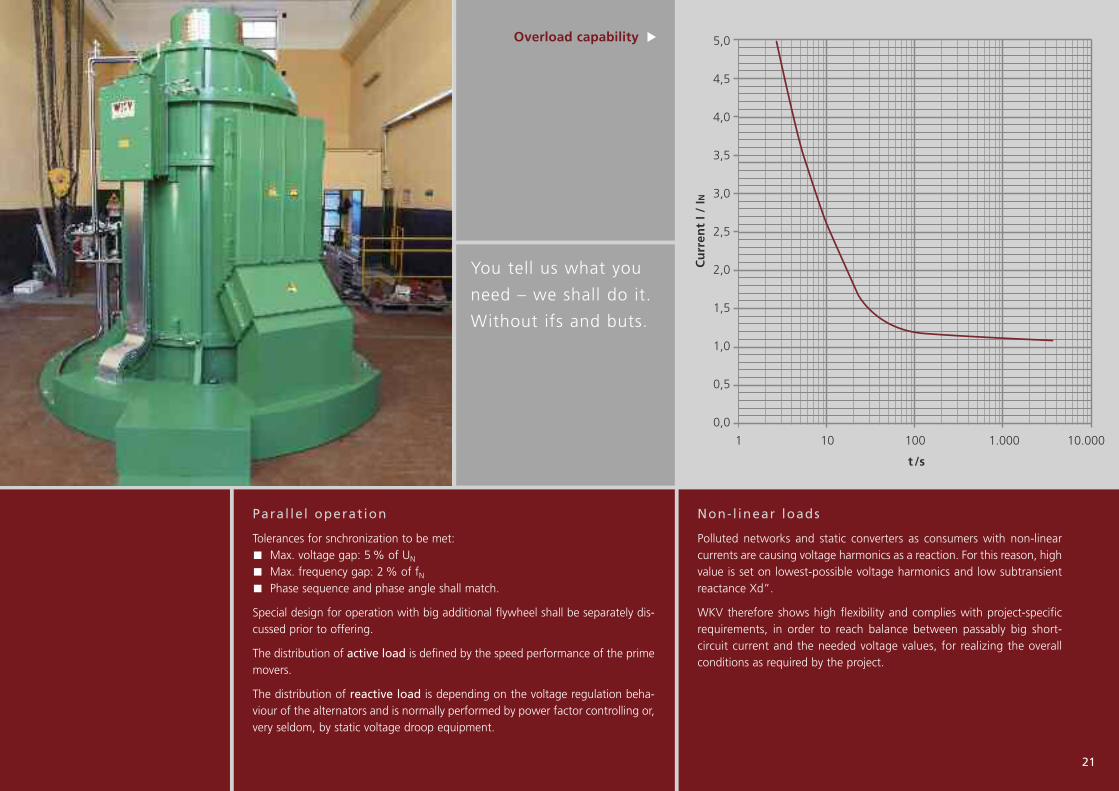
You tell us what you
need – we shall do it.
Without ifs and buts.
5,0
4,5
4,0
3,5
3,0
2,5
2,0
1,5
1,0
0,5
0,0
1 10 100 1.000 10.000
t /s
Cu
rren
t I /
IN
21
Overload capability u
Non-l inear loads
Polluted networks and static converters as consumers with non-linearcurrents are causing voltage harmonics as a reaction. For this reason, highvalue is set on lowest-possible voltage harmonics and low subtransientreactance Xd”.
WKV therefore shows high flexibility and complies with project-specificrequirements, in order to reach balance between passably big short-circuit current and the needed voltage values, for realizing the overallconditions as required by the project.
Paral le l operat ion
Tolerances for snchronization to be met:Max. voltage gap: 5% of UN
Max. frequency gap: 2% of fNPhase sequence and phase angle shall match.
Special design for operation with big additional flywheel shall be separately dis-cussed prior to offering.
The distribution of active load is defined by the speed performance of the primemovers.
The distribution of reactive load is depending on the voltage regulation beha-viour of the alternators and is normally performed by power factor controlling or,very seldom, by static voltage droop equipment.

22
Insulation and protection devices Nothing lives forever, but we are pretty close
One of the most modern impregnationplants in Europe with horizontal andvertical tanks. Impregnated rotors andstators are dried while being rumbled.

23
Alternator protect ion
Thermal winding protectionGenerally min. 2 x 3 PT100 probes for protection of the stator windingagainst thermal overload.
Protection of bearingsGenerally each one PT100 probe radially and, if applicable, axially. Optio -nally, vibration detection of bearings or around bearings will be performed.
Anti-condensation heaterUsed generally for protection against condensate. Connection voltage 230Vsingle phase or to be agreed. The rated heater power is depending on theframe size of the alternator.
Transformers for protection and measuringThe terminal boxes of WKV alternators are generally large enough for hou-sing minimum one set of neutral CTs. The mounting of further current andvoltage transformers can be done on request.
Further protectionThe application of more protective devices such as vibration sensors, speedmeasurement, brakes, rotor and stator earth fault protection etc. can bedone again on request.
Insulat ion system
WKV alternators are produced according to international rules and regulations. For ensuring the best-possibleoperating reliability considering various operating conditions, our engineers have, based on long experience in building electric alternators, developed and adjusted the insulation system in close cooperation with notablemanufacturers.
Thanky to our most-modern impregnation plant, WKV offers VPI impregnation (today our standard system) aswell as Resin Rich impregnation.
All coils are produced in our own plant and tested individually and later again in mounted condition.
A sophisticated tape binding of the winding overhangs prevents movement or deformation of the coil headseven at extreme loading.
The complete insulation system is matching with temperature class “H” (all rotors and low voltage stators) resp.“F” (medium voltage stators).
Examples for optional equipment: Speed detection (top), hydraulic brake(top middle), sliprings for rotor earthfault detection with magnetic brushlifting device (top right).

24
Quality assurance, factory testing Trust is good, control is better
Horizontal alternatorin test field (above)
Test field control desk(left hand side)
Vertical test alignment withangular gear (right hand side)

25
Overview Serial Prototype Specialstests tests tests
1. Measurement of cold resistances x x
2. Rotating field control x x
3. Voltage balance x x
4. Functional test of AVR-System x x
4.1 Adjustment of voltage regulator x x
4.2 Adjustment of underspeed protection x x
4.3 Check of voltage adjustment range x x
4.4 Adjustment of the parallel operation mode/static droop x x
4.5 Adjustment of additional modules / features for AVR x x
5. Load characteristic at p.f. = 0,1 x x
6. Overspeed /runaway speed test x x
7. Vibration measurement x x
8. High voltage test x x
9. Measurement of insulation resistances x x
10. Final check with concentricity check x x
11. Temperature rise test x
12. No-load characteristic, remanent voltage, winding test x
12.1 No-load characteristic x
12.2 Winding test x
12.3 Residual voltage x
13. Short-circuit characteristic, overload test, SCR, Xd x
13.1 Short-circuit characteristic x
13.2 Overload test x
13.3 Short-circuit ratio SCR x
13.4 Evaluation of synchronous reactance Xd x
14. Determination of rated field current x
15. Determination of efficiency x
16. Additional temperature rise test for 110% rated current for 1h x
17. Sudden short circuit test x
18. Harmonic analysis of voltage waveform x
19. Sudden load application at p.f. 0,1, diagram x
20. Noise pressure level measurement x
The WKV test facilities in Gutach/Germany with a total prime mover capa-city of 1.200 kW, most-modern measurement technologies, a comfortablevisitor’s area with every conveníence and a highly motivated team of assay-ers offers optimal conditions for both standard testing and sophisticatedFATs.
After manufacturing, every WKV alternator is taken to our most-moderntest facilities. Our customers are provided with a comprehensive test reportfor every single alternator.
Customers are always welcome to inspect the factory test procedure and tocheck all the complete measuring and test reports that have been compiledduring the entire production process.
Last but not least:
Enjoy the typical Black
Forrest hospitality on
a fac tory tour associa-
ted with the testing
of “your” machine!

26
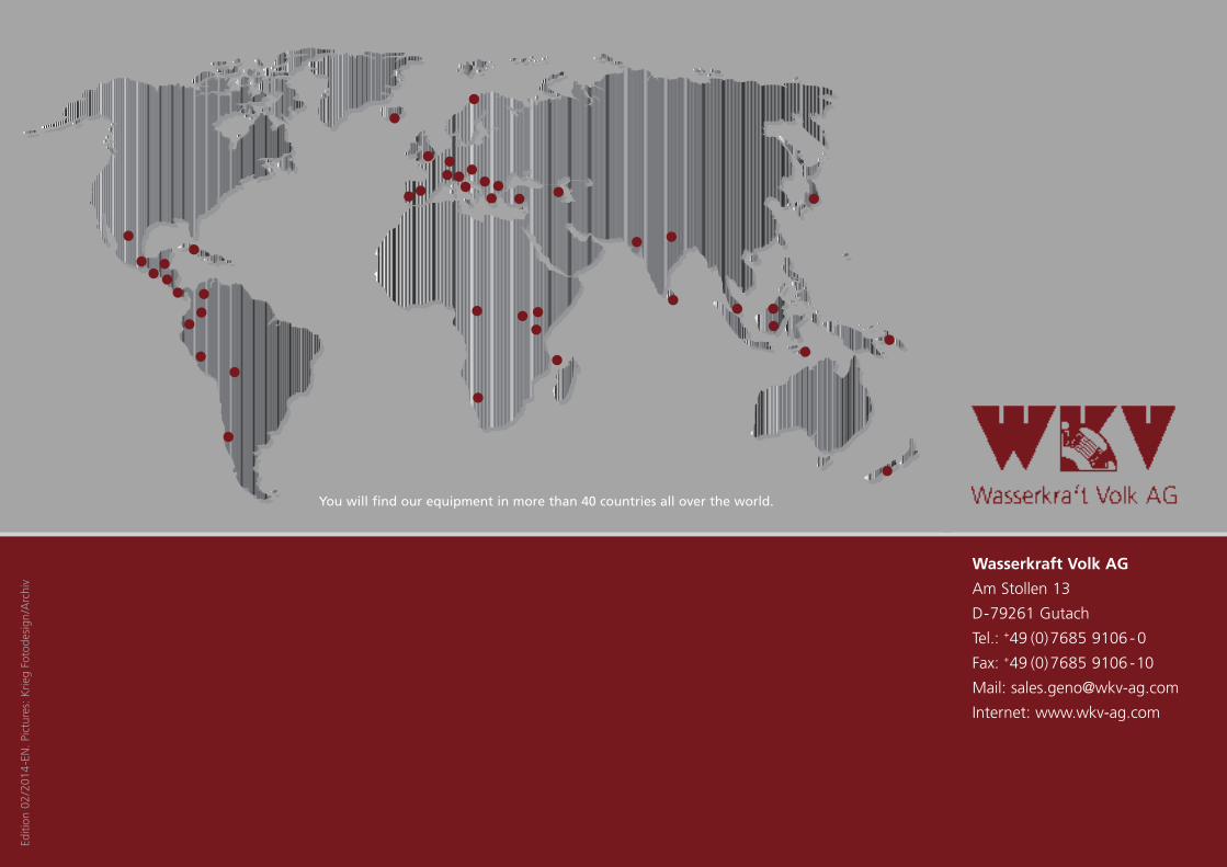
World-wide after sales service If the worst comes to the worst

Service for customers
We at WKV would wish to support you from the beginning, during the preparation process, project work towards crea-ting a technically optimized solution.
On request, your technical staff will receive a systematic training-on-product during the FAT. Of course, also for commis-sioning of your power plant we will provide support if required.
WKV alternators are produced in accordance with internationally proven WKV quality standards. However, even the bestproduct can get damaged or might need a technical check. For this reason, our responsibility does not end with thedelivery of a top-class premium product. The WKV AG is operational worldwide with a network of distribution and salespartners that is standing for quick and reliable support in case of any technical problems.
Wherever we have no representation, we travel. Immediately.
That is our promise.
27
Our obligation to
you, our customers,
does not end when
delivering a top-quality
product!
Wasserkraft Volk AG
Am Stollen 13
D-79261 Gutach
Tel.: +49 (0)7685 9106 -0
Fax: +49 (0)7685 9106 -10
Mail: [email protected]
Internet: www.wkv-ag.com
You will find our equipment in more than 40 countries all over the world.
Edition
02/201
4-EN. Pictures: Krie
g Fotode
sign
/Archiv