Embed Size (px)
Citation preview

Working Draft ProjectAmerican National T10/1799-DStandard
Revision 2527 October 2010
Information technology -SCSI Block Commands – 3 (SBC-3)
This is an internal working document of T10, a Technical Committee of Accredited Standards Committee INCITS (International Committee for Information Technology Standards). As such this is not a completed standard and has not been approved. The contents may be modified by the T10 Technical Committee. The contents are actively being modified by T10. This document is made available for review and comment only.
Permission is granted to members of INCITS, its technical committees, and their associated task groups to reproduce this document for the purposes of INCITS standardization activities without further permission, provided this notice is included. All other rights are reserved. Any duplication of this document for commercial or for-profit use is strictly prohibited.
T10 Technical Editor: Mark EvansWestern Digital Corporation5863 Rue FerrariSan Jose, CA 95138USA
Telephone: 408-363-5257Email: [email protected]
Reference numberISO/IEC 14776-323:200x
ANSI INCITS.***:200x

T10/1799-D Revision 25 27 October 2010
ii Working Draft SCSI Block Commands – 3 (SBC-3)
Points of contact
International Committee for Information Technology Standards (INCITS) T10 Technical Committee
T10 Chair T10 Vice-ChairJohn B. Lohmeyer Mark S. EvansLSI Logic Western Digital Corporation4420 Arrows West Drive 5863 Rue FerrariColorado Springs, CO 80907-3444 San Jose, CA 95138USA USA
Telephone: (719) 533-7560 Telephone: (408) 363-5257Email: [email protected] Email: [email protected]
T10 Web Site: http://www.t10.org
T10 E-mail reflector:Server: [email protected] subscribe send e-mail with ‘subscribe’ in message bodyTo unsubscribe send e-mail with ‘unsubscribe’ in message body
INCITS Secretariat1101 K Street, NWSuite 610Washington, DC 20005USA
Telephone: 202-737-8888Web site: http://www.incits.orgEmail: [email protected]
Information Technology Industry CouncilWeb site: http://www.itic.org
Document DistributionINCITS Online Storemanaged by Techstreet1327 Jones DriveAnn Arbor, MI 48105USA
Web site: http://www.techstreet.com/incits.htmlTelephone: (734) 302-7801 or (800) 699-9277
Global Engineering Documents, an IHS Company15 Inverness Way EastEnglewood, CO 80112-5704USA
Web site: http://global.ihs.comTelephone: (303) 397-7956 or (303) 792-2181 or (800) 854-7179

27 October 2010 T10/1799-D Revision 25
Working Draft SCSI Block Commands – 3 (SBC-3) iii
American National Standardfor Information Technology
SCSI Block Commands – 3 (SBC-3)
SecretariatInformation Technology Industry Council
Approved mm.dd.yy
American National Standards Institute, Inc.
ABSTRACTThis standard specifies the functional requirements for the SCSI Block Commands - 3 (SBC-3) command set. SBC-3 permits SCSI block logical units such as rigid disks to attach to computers and provides the definition for their use.
This standard maintains a high degree of compatibility with the SCSI Block Commands (SBC-2) command set, INCITS 405-2005, and while providing additional functions, is not intended to require changes to presently installed devices or existing software.

T10/1799-D Revision 25 27 October 2010
iv Working Draft SCSI Block Commands – 3 (SBC-3)
Published byAmerican National Standards Institute11 W. 42nd Street, New York, New York 10036Copyright © 2004 by Information Technology Industry Council (ITI).All rights reserved.
No part of this publication may by reproduced in anyform, in an electronic retrieval system or otherwise,without prior written permission of ITI, 1101 K Street, NW Suite 610,Washington, DC 20005.
Printed in the United States of America
American National Standard
Approval of an American National Standard requires verification by ANSI that the requirements for due process, consensus, and other criteria for approval have been met by the standards developer. Consensus is established when, in the judgment of the ANSI Board of Standards Review, substantial agreement has been reached by directly and materially affected interests. Substantial agreement means much more than a simple majority, but not necessarily unanimity. Consensus requires that all views and objections be considered, and that effort be made towards their resolution.
The use of American National Standards is completely voluntary; their existence does not in any respect preclude anyone, whether he has approved the standards or not, from manufacturing, marketing, purchasing, or using products, processes, or procedures not conforming to the standards.
The American National Standards Institute does not develop standards and will in no circumstances give interpretation on any American National Standard. Moreover, no person shall have the right or authority to issue an interpretation of an American National Standard in the name of the American National Standards Institute. Requests for interpretations should be addressed to the secretariat or sponsor whose name appears on the title page of this standard.
CAUTION NOTICE: This American National Standard may be revised or withdrawn at any time. The procedures of the American National Standards Institute require that action be taken periodically to reaffirm, revise, or withdraw this standard. Purchasers of American National Standards may receive current information on all standards by calling or writing the American National Standards Institute.
CAUTION: The developers of this standard have requested that holders of patents that may be required for the implementation of the standard, disclose such patents to the publisher. However, neither the developers nor the publisher have undertaken a patent search in order to identify which, if any, patents may apply to this standard. As of the date of publication of this standard, following calls for the identification of patents that may be required for the implementation of the standard, no such claims have been made. No further patent search is conducted by the developer or the publisher in respect to any standard it processes. No representation is made or implied that licenses are not required to avoid infringement in the use of this standard.

27 October 2010 T10/1799-D Revision 25
Working Draft SCSI Block Commands – 3 (SBC-3) v
Revision History
R.1 Revision 0 (09 September 2005)Revision 0 of SBC-3 is substantially equal to revision 16 of SBC-2. The only differences arise from changes made in SBC-2 discovered during the ISO process. Those changes include:
a) Changed idle condition timer to standby condition timer in item c) of subclause 4.15.1.b) Changed 2 Gigabytes to 1 GiB and 2 Terabytes to 2 TiB in two places in note 10 in subclause 5.5.
The 2 was change to a 1 because there are 21 bits in the LOGICAL BLOCK ADDRESS field (i.e., 1F_FFFF is 2 097 151 that * 512 is 1 073 741 312 which is 1 GiB).
Removed the CORRCT bit from the WRITE LONG (16) CDB as it was never supposed to be added to this command. It's not in SCSI-2 or SBC for WRITE LONG (10) and 03-383r1 did not ask for it. It showed up in sbc2r11.
R.2 Revision 1 (16 September 2005)a) Incorporated the following proposals:
A) 04-198r5 - Background Media Scan;B) 04-371r2 - SPC-4: Enable Background Operation Error Reporting Bit; andC) 05-101r1 - SBC-2 Validation of Protection Information.
R.3 Revision 2 (22 September 2005)a) Incorporated the following proposals:
A) 05-299r1 - Correct Log Page Format Tables in SPC-4, SBC-3, & SAS-2; andB) 05-313r0 - SBC-3: Change to background medium scan.
R.4 Revision 3 (16 November 2005)a) Incorporated the following proposals:
A) 05-156r7 - SBC-3, SPC-4: Application ownership of protection information Reference Tag;B) 05-317r3 - SMC-3, SPC-4, SBC-3, and SSC-3: Remove Attached Media Changer model; andC) 05-374r2 - SBC-3: SPC-4: Disabling Reassign on Write Long Logical Blocks.
R.5 Revision 4 (10 February 2006)a) Incorporated the following proposals:
A) 05-157r9 - SPC Security Commands proposal (in an E-mail it was pointed out that the SERCURITY PROTOCOL IN and SECURITY PROTOCOL OUT commands need to be added to the SBC-3 commands list table);
B) 05-340r3 - SBC-3 SPC-4 Background scan additions;C) 05-368r2 - SPC-4 SBC-3 SMC-3 Allow more commands through Write Exclusive reservations;
andD) 05-383r4 - SPC-4: Deferred microcode downloads.
In addition the following editorial corrections were received from E-mail were incorporated:
a) the initiator control (IC) enable bit description had the SIZE bit polarity backwards;b) changed filed to field;c) WRITE SAME (32) was placed into the list of medium access commands in the Protection types
overview subclause;d) the field name P_TYPEABLE in table 19 (FMTPINFO bit, RTO_REQ bit, and PROTECTION FIELD USAGE field)
footnote d was changed to P_TYPE; ande) the field name DATA BLOCK GUARD in table 80 (LBDATA bit and PBDATA bit) in row 0 0 was changed to
LOGICAL BLOCK GUARD.
R.6 Revision 5 (11 May 2006)a) Incorporated the following proposals:

T10/1799-D Revision 25 27 October 2010
vi Working Draft SCSI Block Commands – 3 (SBC-3)
A) 06-248r1 - Proposal to remove the PREVENT ALLOW MEDIUM REMOVAL (PAMR) command from SPC-4
In addition the following editorial corrections were received from E-mail were incorporated:
a) The following sentence occurs on SBC-3 rev. 3, page 122, first paragraph under table 110, last sentence of paragraph; and also on page 124, first paragraph under table 111, last sentence of paragraph:
“To determine the number of blocks at which the logical unit is currently formatted, the application client shall use the READ CAPACITY command (see 5.11) rather than the MODE SELECT command.”
In both cases, the “MODE SELECT” needs to be replaced with “MODE SENSE”. To use the “select” operation is nonsensical if the purpose is to discover the current block size of the disk drive.
R.7 Revision 6 (24 July 2006)a) Incorporated the following proposals:
A) 06-259r1 - SAM-4, et al.: making linked commands obsolete;B) 06-274r1 - SPC-4 SBC-3 REQUEST SENSE and Stopped power condition; andC) 06-323r1 - SAM-4 SPC-4 et al Multiple service delivery subsystem editorial tweaks.
R.8 Revision 7 (22 September 2006)a) Incorporated the following proposals:
A) 06-034r5 - SBC-3 Physical blocks; andB) 06-350r0 - SPC-4/SBC-3: Power conditions state machine clarification.
In addition the following editorial corrections were received from E-mail were incorporated:
a) In the Background Scan Results log page (section 6.2.2) in table 101 on page 119, there seems to be a missing “scan” in the row for code 08h. It currently reads:
“Background medium halted, waiting...”.
GAH: Agreed, it should read “Background medium scan halted, waiting...”. I note that the word “medium” is not present in the descriptions of other code rows, maybe that word should be removed for consistency.
GOP: The word “medium” was added to all the descriptions of other code rows to make it consistent with the rest of the clause.
b) In “Background medium scan parameter format” for parameter code 0001h to 0800h shown in table 102 the “accumulated power on minutes” field is defined on page 121 as “The ACCUMULATED POWER ON MINUTES field indicates the number of minutes the device server has been powered on since manufacturing.” That is the same definition of the same named field found in the “Background medium scan status parameter format” (for parameter code 0) shown in table 99. Shouldn't the description associated with table 102 be referencing when the error associated with that parameter number was logged [similar to the way the self test log page outputs its results]?
GAH: I agree. It should say “The ACCUMULATED POWER ON MINUTES field indicates the number of minutes the device server has been powered on since manufacturing at the time the background scan error occurred.”
R.9 Revision 8 (18 January 2007)Fixed the byte numbering in the READ CAPACITY (16) parameter data table in 5.16.2.
Based on the following E-mail from Mark Evans pointing out error in the incorporation of proposal 05-340r3 changes were made to table 111 and table 114 and a description of the DS bit and the SPF bit were placed under table 108:

27 October 2010 T10/1799-D Revision 25
Working Draft SCSI Block Commands – 3 (SBC-3) vii
While going through SBC-3, I see that table 102 (parameter control bits for Background Scanning Status log parameter) looks goofy. I think it should look like table 194 in SAS. I'm making that change in our internal document and recommend that you make the change in SBC.
Incorporated the following proposals:
a) 06-479r1 - Mandate CAPACITY DATA HAS CHANGED unit attention; andb) 06-393r3 - On-disk bitmap support.
R.10 Revision 8a (18 January 2007)The ORWRITE CDB table title was fixed and the ORWRITE operation code in the CDB was corrected.
R.11 Revision 9 (22 March 2007)Based on the following 1/23/2007 E-mail from Mark Evans pointing out a duplicate entry between subclause 4.17 Protection information model and subclause 5.31 WRITE AND VERIFY (10) command. The duplicate wording that needs to be deleted is from 5.31 WRITE AND VERIFY (10) command and is:
If the P_TYPE bit is set to one in the READ CAPACITY (16) parameter data (see 5.13), the device server shall terminate this command with CHECK CONDITION status with the sense key set to ILLEGAL REQUEST and the additional sense code set to INVALID COMMAND OPERATION CODE.During the investigation of this more duplicate wording was found in subclause 5.38 WRITE SAME (16) command. This duplication wording that needs to be deleted is:If the P_TYPE bit is set to one in the READ CAPACITY (16) parameter data (see 5.13), the device server shall terminate the command with CHECK CONDITION status with the sense key set to ILLEGAL REQUEST and the additional sense code set to INVALID COMMAND OPERATION CODEIn both cases the duplicate wording should have been removed as part of T10/05-156 revision 7.
Based on the following 1/26/2007 E-mail from Rob Elliott editorial changes were made as recommended in the e-mail. The only recommend change not made was to change ORWRITE to ORWRITE (16). Instead all the ORWRITE (16)s were changed to ORWRITE.
1) On page 55, this text needs small caps and the table references need to be fixed:The device server shall:
a) check protection information read from the medium based on the ORPROTECT field as described in tableyy2; and
b) check protection information transferred from the data-out buffer based on the ORPROTECT field as described in table yy3.
2) In table 3 (reservations), on page 29, and on page 30, ORWRITE s/b ORWRITE (16)3) In the table of tables on page xiii, the prevent field doesn't show up in small caps like the others.4) On page 34 and 35, several of the equations are truncated on the left and right. The reason is the font
size grew - the Equation format or character format is messed up on those lines.
Based on the following 2/8/2007 emails from Dave Peterson and Rob Elliott pointing out a badly worded sentence that sentence was corrected.
Dave Peterson:Sentence in question:Subclause 5.2.2.3 first paragraph, first sentence on physical page 52:“When the SI bit is set to one, the device server need not write the initialization pattern over the header and other header and other parts of the medium not previously accessible to the application client.”The extra “...and other header...” appears odd. Please clarify.Rob Elliott:I agree with David's fix.
Based on the following email from Doug Gilbert received on 2/23/2007 I added in cross-references to the footnote in table 84. The cross-references were added to all the yes terms in the 3rd column.
George, you should delete the spurious “and other header” words from the SI bit paragraph SBC-3. That was broken in sbc2r12 while incorporating editor's meeting comments to fix a parenthetical expression without an e.g. or i.e.

T10/1799-D Revision 25 27 October 2010
viii Working Draft SCSI Block Commands – 3 (SBC-3)
In section 5.35 on WRITE LONG(10) there is table 84 which has a footnote “a”. It is hanging because thereseems nothing in the main table it refers to. My guess is that it refers to the third column header which starts “More than one logical block...”.
Incorporated the following proposals:
a) 07-110r0 - Update Block Limits VPD Page for ORWRITE; andb) 07-113r0 - Maximum transfer sizes for XPWRITE XDWRITE XDREAD PRE-FETCH.
R.12 Revision 10 (17 May 2007)Incorporated the following proposals:
a) 07-203r0 - SBC-3 SPC-4 Block Device Characteristics VPD page and medium rotation rate field; andb) 07-208r0 - SBC-3 Rename field in READ CAPACITY(16) parameter data.
R.13 Revision 11 (19 July 2007)All mode page format tables have been updated to include the SubPage Format (SPF) bit.
Incorporated the following proposals:
a) 07-257r1 - Prohibited needed as a keyword in SPC-4;b) 07-271r1 - SBC-3, Clarifications for Background Scan Results log page;c) 07-281r1 - SPC-4, SBC-3, #Except INQUIRY, REPORT LUNS, and REQUEST SENSE#; andd) 07-302r1 - SBC-3 WRITE LONG Additional Sense code option to support SAT-2.
Based on the following email from Rob Elliott received on 5/16//2007:
1. SBC-3 uses both “media access commands” (from changes made in the DIF area) and “medium access commands.” SBC-2 only used “medium access commands.”
I changed all the “media access commands” to “medium access commands”.
As a result of 07-271 references to generic fields (e.g., OPERATION CODE field, PAGE CODE field, PAGE LENGTH field) were added under the tables where those fields were defined.
R.14 Revision 12 (11 November 2007)Incorporated the following proposals:
a) 07-472r0 - Reporting nominal form factor;b) 07-447r1 - Read-Write Error Recovery clarifications; andc) 07-481r1 - Mention that DIF equals protection information.
Made editorial changes based on the following email received from Rob Elliott on 7/24/2007
You added wording like this to many sections: “The OPERATION CODE field is defined in SPC-4 shall be set to the value defined in table 72." but “shall” needs to be “and shall”. I see a few that are broken, though: After table 81, it points to table 72. After table 91, it points to table 90.The wording for SPF bit in the mode pages: “A SubPage Format (SPF) bit set to zero indicates that the page_0 mode page format is being used (see SPC-4).” should probably be: “The SubPage Format (SPF) bit is defined in SPC-4 and shall be set to the value defined in table xx.”xx.”” (probably combined with the PAGE CODE sentence in all cases) Table 102, bytes 4-19 - parameters s/b parameter (there's only one) Table 104 - add (MSB)/(LSB) on the last field Table 112 - in the sentence after this table, the period is on the wrong line. Table 113, 115 - change 3h to 03h Editor's note 1: Either that proposal or the editor deleted the wrong line from SBC-2 when obsoleting

27 October 2010 T10/1799-D Revision 25
Working Draft SCSI Block Commands – 3 (SBC-3) ix
linked commands. It should just be “CONDITION MET” not “INTERMEDIATE-CONDITION MET”. See SBC-2's original wording - the LINK bit set to zero sentences are the ones that should have remained.Added the control byte reference to SAM-4 for all the CDBs.
Made editorial changes as noted in the following email received from Gerry Houlder on 11/06/2007:
This inconsistent behavior was noted by an engineer at Seagate while reviewing Protection Information behavior in SBC-3. It would seem to be more appropriate to call out 05/24 sense instead of 05/20 to be consistent with products that report 05/24 for reserved fields.
R.15 Revision 13 (24 January 2008)Made all binary and hexadecimal numbers have a consistent format, separating groups of four digits with underscores. Changed the conventions clause (see clause 3.5) to define this format.
Incorporated the following proposals:
a) 07-451r1 - WRITE LONG COR_DIS and WR_UNCOR interaction;b) 07-454r5 - Capability based Command Security;c) 07-459r4 - Unit attention condition queuing;d) 08-041r1 - Use period as decimal separator in T10 standards;
Made editorial changes as noted in the following email received from Rob Elliott on 01/03/2008:
- add the subpage code column to the table of log page codes- add 00h/FFh as Supported Log Pages and Subpages to the table of log page codes- add 01h-3Eh/FFh as Supported Subpages to the table of log page codes- add 18h/00h-3Eh as Protocol Specific Port log pages to the table of log page codes- add the DS bit and SPF bit (0b) to byte 0 of any log page definitions- add the SUBPAGE CODE field (00h) to byte 1 of any log page definitions- make sure the command set table agrees with the SPC-4 annex about the page names, reserved and
vendor-specific ranges, etc.
R.16 Revision 14 (20 March 2008)Incorporated the following proposals:
a) 08-139r1 - START STOP UNIT command additions.
Made the editorial change in 4.18 based on an email from Fred Knight: changed “idle” to “standby” in list item (C) in the bulleted list for how to process a REQUEST SENSE command while in the standby power condition.
Updated the definition of the PREVENT ALLOW MEDIUM REMOVAL command to be as proposed in 05-317r3 based on emails from Rob Elliott.
Made other editorial changes as denoted by change bars, including:
- added definitions for device server, I_T nexus, logical unit, SCSI target device, and unit attention condition
- added requirement that, if the medium in a direct-access block device is removable, and the medium is removed, then the device server shall establish a unit attention condition
Made other minor editorial and formatting changes not indicated by change bars.
R.17 Revision 15 (15 May 2008)Incorporated the following proposals:
a) 08-156r2 -Non-volatile cache becoming volatile.
Made other minor editorial and formatting changes not indicated by change bars.

T10/1799-D Revision 25 27 October 2010
x Working Draft SCSI Block Commands – 3 (SBC-3)
R.18 Revision 16 (25 August 2008)Incorporated the following proposals:
a) 08-116r3 - SBC-3 SPC-4: Protection Type 3 Reference Tag Clarification.
Based on an email exchange between Mark Evans and Rob Elliott, changed the following sentence in 4.9 Medium defects from, “During a self-test operation (see SPC-4), the device server shall ignore pseudo unrecoverable errors with correction disabled and shall process the pseudo unrecoverable errors with correction disabled.” to “During a self-test operation (see SPC-4), the device server shall ignore pseudo unrecoverable errors with correction disabled and shall process the pseudo unrecoverable errors with correction enabled.”
The conventions subclause was updated to include the latest descriptions of the conventions for lettered and numbered lists.
The definition for how a range of numeric values are represented in this standard was added, and the attempt was made to find all instances of “through”, “-”, and other representations where they were used to represent a range of numbers and replaced each instance with “to” to conform to this definition.
Other minor editorial and formatting changes were made that are not indicated by change bars.
R.19 Revision 17 (17 November 2008)Incorporated the following proposals:
a) 08-145r3 - Capability-based Command Security (CbCS) [the rewrite];b) 08-192r1 - SBC-3 Model for encrypting disk drives; andc) 08-450r1 - Add Restricted keyword to the Style Guide.
Minor editorial corrections were made, several based on email input, which are indicated by change bars.
Other minor editorial and formatting changes were made that are not indicated by change bars.
R.20 Revision 18 (23 February 2009)Incorporated the following proposals:
a) 08-396r3 - SPC-4/SBC-3: Reporting support for all DIF typesb) 09-007r0 - SBC-3: REASSIGN BLOCKS and CbCS;c) 09-054r1 - SPC-4/SBC-3/SPL: Adding more idle power options;d) 08-356r5 - SBC-3: Thin Provisioning Commands; ande) 08-415r4 - SBC-3/SPC-4: Adding a Protection Information Interval.
Based on an email exchange with Dan Colegrove and Rob Elliot, clarified the table defining the values in the REASSIGN STATUS field (see table 132) in the Background Scan Results log page (see 6.3.2) as was intended by proposal 05-340r3.
Minor editorial corrections were made, several based on email input, which are indicated by change bars.
Other editorial and formatting changes were made that may not be indicated by change bars.
R.21 Revision 19 (29 May 2009)Incorporated the following proposals:
a) 09-038r3 - SBC-3: More background scan clean-up;b) 09-069r0 - SBC-3: Minor consistence adjustment for XOR commands; andc) 09-153r1 - SBC-3: Thin Provisioning per LBA cleanup and granularity.
Minor editorial corrections were made, several based on email input, which are indicated by change bars.
Other editorial and formatting changes were made that may not be indicated by change bars.

27 October 2010 T10/1799-D Revision 25
Working Draft SCSI Block Commands – 3 (SBC-3) xi
R.22 Revision 20 (10 September 2009)Incorporated the following proposals:
a) 08-341r6 - SBC-3 Thin Provisioning GET LBA STATUS Commandb) 09-088r2 - Allow vendor specific log parameters in Log page 15h;c) 09-160r2 - Protection Information settings during capacity change;d) 09-202r1 - Obsolete commands and pages in SBC-3; ande) 09-011r8 - SBC-3 Thin Provisioning Thresholds.
Where they were not already, the tables defining the codes for the diagnostic parameters, log parameters, mode parameters, and vital product data (VPD) parameters were moved to the beginning of their respective clauses, and the parameters were placed in alphabetical order.
Minor editorial corrections were made, several based on email input, which are indicated by change bars.
Other editorial and formatting changes were made that may not be indicated by change bars.
R.23 Revision 21 (25 November 2009)Incorporated the following proposals:
a) 09-004r4 - SBC-3: Host alignment detection;b) 09-088r2 - SBC-3: GET LBA STATUS w/ normalized Allocation Length definition;c) 09-322r2 - SBC-3: Add log page for solid state drive (SSD);d) 09-365r1 - SBC-3: Incorrect description of LOWIR bit effect in table 118;e) 09-372r1 - SBC-3: Verify CDB - Unrecovered Read Error; andf) 09-380r1 - SBC: FORMAT UNIT command fix.
Added a clause describing state diagram notation into clause 3, Definitions, symbols, acronyms, keywords, and conventions.
Minor editorial corrections were made, several based on email input, which are indicated by change bars.
Other editorial and formatting changes were made that may not be indicated by change bars.
R.24 Revision 22Incorporated the following proposals:
a) 09-100r5 - SBC-3: Atomic COMPARE AND WRITE command;b) 09-241r6 - SBC-3, SPC-4, SAM-5: SCSI Referrals;c) 09-272r6 - SBC-3: Thin Provisioning: Anchored;d) 09-357r4 - SPC-4, SBC-3: Relationship between power conditions and background tasks;e) 10-005r1 - SPC-4/SBC-3: Add Disable PI Check on xxPROTECT=0 feature; andf) 10-044r2 - SBC-3: More Thin Provisioning clarifications.
Modified the format of the UNMAP block descriptor table based on discussion with Fred Knight.
Other minor editorial and formatting changes were made that are not indicated by change bars.
R.25 Revision 23Incorporated the following proposals:
a) 10-080r2 - SBC-3: TP Threshold notification to Single Initiator vs. Multi-Initiatorb) 10-133r4 - SPC-4/SBC-3: Pollable Device State model;c) 10-137r0 - SBC-3: VRPROTECCT with BYTCHK set to one — byte-by-byte comparison correction;d) 10-148r1 - SPC-4/SBC-3: More about power conditions and background tasks;e) 10-161r1 - SPC-4/SBC-3/SSC-4/ADC-3/SAT-3: VPD page generic format;f) 10-179r1 - SPC-4/SBC-3: Remove implicit head of queue rule that is in SAM-5; andg) 10-210r3 - SPC-4/SBC-3: Tweaks to power state machines found during SPL LB Resolution.
Made other minor editorial and formatting changes not indicated by change bars.

T10/1799-D Revision 25 27 October 2010
xii Working Draft SCSI Block Commands – 3 (SBC-3)
R.26 Revision 24Incorporated the following proposal:
a) 10-115r2 - SPC-4/SBC-3: Power condition transition
The editor erred when he included 10-210r3 in revision 23 of this draft standard, as he had assumed that all of the material from that proposal had been included in 10-115r2. However, this was not the case. So, the relevant portions of 10-115r2 that were not duplicated in 10-210r3 are now included in this draft. Because of the interactions between these two proposals, no change bars were removed from the previous revision of this draft. The indicated changes in this revision are from both revision 23 and revision 24 of this draft standard.
Made other minor editorial and formatting changes not indicated by change bars.
R.27 Revision 25Incorporated the following proposals:
a) 09-262r8 SBC-3: Bitmaps on Disk - Detailed Changes;b) 10-162r2 SPC-4/SBC-3: Application Tag mode page;c) 10-233r6 - SBC-3: Logical Block Provisioning Management;d) 10-269r1 - SBC-3: Get LBA Status parameter data length fix; ande) 10-280r1 - SPC-4/SBC-3: Reject Write Without Protection Information.
Made minor editorial corrections, several based on email input, which are indicated by change bars.
Made other minor editorial and formatting changes, which are not indicated by change bars.

27 October 2010 T10/1799-D Revision 25
Working Draft SCSI Block Commands – 3 (SBC-3) xiii
ContentsPage
1 Scope ............................................................................................................................................................. 1
2 Normative References ................................................................................................................................... 22.1 Normative references overview ................................................................................................................ 22.2 Approved references ................................................................................................................................ 22.3 References under development ............................................................................................................... 3
3 Definitions, symbols, acronyms, keywords, and conventions ........................................................................ 43.1 Definitions................................................................................................................................................. 43.2 Symbols.................................................................................................................................................... 83.3 Acronyms.................................................................................................................................................. 93.4 Keywords.................................................................................................................................................. 93.5 Conventions............................................................................................................................................ 10
3.5.1 Editorial conventions......................................................................................................................... 103.5.2 Numeric conventions ........................................................................................................................ 103.5.3 Lists conventions .............................................................................................................................. 11
3.5.3.1 Lists conventions overview.......................................................................................................... 113.5.3.2 Unordered lists ............................................................................................................................ 113.5.3.3 Ordered lists ................................................................................................................................ 12
3.5.4 Notation for state diagrams............................................................................................................... 123.5.5 Precedence....................................................................................................................................... 12
4 Direct-access block device type model ........................................................................................................ 134.1 Direct-access block device type model introduction............................................................................... 134.2 Direct-access block device type model overview ................................................................................... 134.3 Media examples ..................................................................................................................................... 14
4.3.1 Media examples overview................................................................................................................. 144.3.2 Rotating media.................................................................................................................................. 144.3.3 Memory media .................................................................................................................................. 15
4.4 Removable medium................................................................................................................................ 154.4.1 Removable medium overview........................................................................................................... 154.4.2 Removable medium with an attached media changer ...................................................................... 15
4.5 Logical blocks ......................................................................................................................................... 164.6 Physical blocks ....................................................................................................................................... 164.7 Logical block provisioning....................................................................................................................... 20
4.7.1 Logical block provisioning overview.................................................................................................. 204.7.2 Full provisioning ................................................................................................................................ 204.7.3 Logical block provisioning management ........................................................................................... 20
4.7.3.1 Logical block provisioning management overview ...................................................................... 204.7.3.2 Resource provisioning................................................................................................................. 214.7.3.3 Thin provisioning ......................................................................................................................... 214.7.3.4 Unmap operations ....................................................................................................................... 22
4.7.3.4.1 Unmap operations overview .................................................................................................. 224.7.3.4.2 WRITE SAME command unmap operations ......................................................................... 22
4.7.3.5 Autonomous transitions of unmapped LBAs ............................................................................... 234.7.3.6 Logical block provisioning management and protection information........................................... 234.7.3.7 Resource exhaustion considerations .......................................................................................... 234.7.3.8 Logical block provisioning thresholds.......................................................................................... 23
4.7.3.8.1 Logical block provisioning thresholds overview ..................................................................... 234.7.3.8.2 Logical block provisioning armed decreasing thresholds ...................................................... 244.7.3.8.3 Logical block provisioning armed increasing thresholds........................................................ 254.7.3.8.4 Logical block provisioning threshold notification.................................................................... 25
4.7.4 Logical block provisioning state machine.......................................................................................... 264.7.4.1 Logical block provisioning state machine overview..................................................................... 26

T10/1799-D Revision 25 27 October 2010
xiv Working Draft SCSI Block Commands – 3 (SBC-3)
4.7.4.2 TP1:Mapped state ....................................................................................................................... 274.7.4.2.1 TP1:Mapped state description ............................................................................................... 274.7.4.2.2 Transition TP1:Mapped to TP2:Deallocated.......................................................................... 274.7.4.2.3 Transition TP1:Mapped to TP3:Anchored ............................................................................. 27
4.7.4.3 TP2:Deallocated state ................................................................................................................. 284.7.4.3.1 TP2:Deallocated state description ......................................................................................... 284.7.4.3.2 Transition TP2:Deallocated to TP1:Mapped.......................................................................... 284.7.4.3.3 Transition TP2:Deallocated to TP3:Anchored ....................................................................... 28
4.7.4.4 TP3:Anchored state..................................................................................................................... 284.7.4.4.1 TP3:Anchored state description............................................................................................. 284.7.4.4.2 Transition TP3:Anchored to TP1:Mapped ............................................................................. 294.7.4.4.3 Transition TP3:Anchored to TP2:Deallocated ....................................................................... 29
4.8 Ready state ............................................................................................................................................ 294.9 Initialization............................................................................................................................................. 304.10 Write protection .................................................................................................................................... 304.11 Medium defects .................................................................................................................................... 314.12 Write failures......................................................................................................................................... 324.13 Caches ................................................................................................................................................. 324.14 Implicit HEAD OF QUEUE command processing ...................................................................................... 344.15 Reservations......................................................................................................................................... 354.16 Error reporting ...................................................................................................................................... 37
4.16.1 Error reporting overview.................................................................................................................. 374.16.2 Processing pseudo unrecovered errors .......................................................................................... 384.16.3 Block commands sense data descriptor ......................................................................................... 384.16.4 User data segment referral sense data descriptor.......................................................................... 39
4.17 Model for XOR commands ................................................................................................................... 414.17.1 Model for XOR commands overview .............................................................................................. 414.17.2 Storage array controller supervised XOR operations ..................................................................... 41
4.17.2.1 Storage array controller supervised XOR operations overview................................................. 414.17.2.2 Update write operation .............................................................................................................. 414.17.2.3 Regenerate operation................................................................................................................ 424.17.2.4 Rebuild operation ...................................................................................................................... 42
4.17.3 Array subsystem considerations ..................................................................................................... 434.17.3.1 Array subsystem considerations overview ................................................................................ 434.17.3.2 Buffer full status handling .......................................................................................................... 434.17.3.3 Access to an inconsistent stripe ................................................................................................ 43
4.17.4 XOR data retention requirements ................................................................................................... 434.18 START STOP UNIT and power conditions........................................................................................... 44
4.18.1 START STOP UNIT and power conditions overview...................................................................... 444.18.2 Processing of concurrent START STOP UNIT commands............................................................. 444.18.3 Managing media access commands during a change to the active power condition ..................... 444.18.4 Stopped Power Condition ............................................................................................................... 444.18.5 START STOP UNIT and power conditions state machine.............................................................. 45
4.18.5.1 START STOP UNIT and power conditions state machine overview......................................... 454.18.5.2 SSU_PC0:Powered_On state ................................................................................................... 47
4.18.5.2.1 SSU_PC0:Powered_On state description ........................................................................... 474.18.5.2.2 Transition SSU_PC0:Powered_On to SSU_PC4:Active_Wait ............................................ 474.18.5.2.3 Transition SSU_PC0:Powered_On to SSU_PC8:Stopped.................................................. 47
4.18.5.3 SSU_PC1:Active state .............................................................................................................. 474.18.5.3.1 SSU_PC1:Active state description ...................................................................................... 474.18.5.3.2 Transition SSU_PC1:Active to SSU_PC5:Wait_Idle ........................................................... 474.18.5.3.3 Transition SSU_PC1:Active to SSU_PC6:Wait_Standby .................................................... 474.18.5.3.4 Transition SSU_PC1:Active to SSU_PC10:Wait_Stopped.................................................. 48
4.18.5.4 SSU_PC2:Idle state .................................................................................................................. 484.18.5.4.1 SSU_PC2:Idle state description .......................................................................................... 484.18.5.4.2 Transition SSU_PC2:Idle to SSU_PC4:Active_Wait ........................................................... 484.18.5.4.3 Transition SSU_PC2:Idle to SSU_PC5:Wait_Idle ............................................................... 48

27 October 2010 T10/1799-D Revision 25
Working Draft SCSI Block Commands – 3 (SBC-3) xv
4.18.5.4.4 Transition SSU_PC2:Idle to SSU_PC6:Wait_Standby ........................................................ 494.18.5.4.5 Transition SSU_PC2:Idle to SSU_PC7:Idle_Wait ............................................................... 494.18.5.4.6 Transition SSU_PC2:Idle to SSU_PC10:Wait_Stopped...................................................... 49
4.18.5.5 SSU_PC3:Standby state ........................................................................................................... 494.18.5.5.1 SSU_PC3:Standby state description ................................................................................... 494.18.5.5.2 Transition SSU_PC3:Standby to SSU_PC4:Active_Wait .................................................... 494.18.5.5.3 Transition SSU_PC3:Standby to SSU_PC6:Wait_Standby................................................. 494.18.5.5.4 Transition SSU_PC3:Standby to SSU_PC7:Idle_Wait ........................................................ 504.18.5.5.5 Transition SSU_PC3:Standby to SSU_PC9:Standby_Wait................................................. 504.18.5.5.6 Transition SSU_PC3:Standby to SSU_PC10:Wait_Stopped .............................................. 50
4.18.5.6 SSU_PC4:Active_Wait state ..................................................................................................... 514.18.5.6.1 SSU_PC4:Active_Wait state description ............................................................................. 514.18.5.6.2 Transition SSU_PC4:Active_Wait to SSU_PC1:Active ....................................................... 52
4.18.5.7 SSU_PC5:Wait_Idle state ......................................................................................................... 524.18.5.7.1 SSU_PC5:Wait_Idle state description ................................................................................. 524.18.5.7.2 Transition SSU_PC5:Wait_Idle to SSU_PC2:Idle ............................................................... 52
4.18.5.8 SSU_PC6:Wait_Standby state.................................................................................................. 524.18.5.8.1 SSU_PC6:Wait_Standby state description.......................................................................... 524.18.5.8.2 Transition SSU_PC6:Wait_Standby to SSU_PC3:Standby................................................. 52
4.18.5.9 SSU_PC7:Idle_Wait state ......................................................................................................... 524.18.5.9.1 SSU_PC7:Idle_Wait state description ................................................................................. 524.18.5.9.2 Transition SSU_PC7:Idle_Wait to SSU_PC2:Idle ............................................................... 53
4.18.5.10 SSU_PC8:Stopped state......................................................................................................... 534.18.5.10.1 SSU_PC8:Stopped state description................................................................................. 534.18.5.10.2 Transition SSU_PC8:Stopped to SSU_PC4:Active_Wait .................................................. 534.18.5.10.3 Transition SSU_PC8:Stopped to SSU_PC7:Idle_Wait ...................................................... 544.18.5.10.4 Transition SSU_PC8:Stopped to SSU_PC9:Standby_Wait .............................................. 54
4.18.5.11 SSU_PC9:Standby_Wait state................................................................................................ 544.18.5.11.1 SSU_PC9:Standby_Wait state description........................................................................ 544.18.5.11.2 Transition SSU_PC9:Standby_Wait to SSU_PC3:Standby............................................... 55
4.18.5.12 SSU_PC10: Wait_Stopped state............................................................................................. 554.18.5.12.1 SSU_PC10:Wait_Stopped state description...................................................................... 554.18.5.12.2 Transition SSU_PC10:Wait_Stopped to SSU_PC8:Stopped ............................................ 55
4.19 Protection information model................................................................................................................ 554.19.1 Protection information overview...................................................................................................... 554.19.2 Protection types .............................................................................................................................. 55
4.19.2.1 Protection types overview ......................................................................................................... 554.19.2.2 Type 0 protection....................................................................................................................... 564.19.2.3 Type 1 protection....................................................................................................................... 574.19.2.4 Type 2 protection....................................................................................................................... 574.19.2.5 Type 3 protection....................................................................................................................... 58
4.19.3 Protection information format.......................................................................................................... 594.19.4 Logical block guard ......................................................................................................................... 62
4.19.4.1 Logical block guard overview .................................................................................................... 624.19.4.2 CRC generation......................................................................................................................... 624.19.4.3 CRC checking ........................................................................................................................... 634.19.4.4 CRC test cases ......................................................................................................................... 63
4.19.5 Application of protection information............................................................................................... 634.19.6 Protection information and commands ........................................................................................... 63
4.20 Grouping function ................................................................................................................................. 644.21 Background scan operations ................................................................................................................ 64
4.21.1 Background scan overview ............................................................................................................. 644.21.2 Background pre-scan operations .................................................................................................... 65
4.21.2.1 Enabling background pre-scan operations................................................................................ 654.21.2.2 Suspending and resuming background pre-scan operations .................................................... 654.21.2.3 Halting background pre-scan operations................................................................................... 66
4.21.3 Background medium scan .............................................................................................................. 66

T10/1799-D Revision 25 27 October 2010
xvi Working Draft SCSI Block Commands – 3 (SBC-3)
4.21.3.1 Enabling background medium scan operations ........................................................................ 664.21.3.2 Suspending and resuming background medium scan operations............................................. 664.21.3.3 Halting background medium scan operations ........................................................................... 67
4.21.4 Interpreting the logged background scan results ............................................................................ 674.22 Association between commands and CbCS permission bits ............................................................... 694.23 Deferred microcode activation.............................................................................................................. 704.24 Model for uninterrupted sequences on LBA ranges ............................................................................. 704.25 Referrals ............................................................................................................................................... 71
4.25.1 Referrals overview .......................................................................................................................... 714.25.2 Discovering referrals ....................................................................................................................... 714.25.3 Discovering referrals example ........................................................................................................ 73
4.25.3.1 Referrals example with no user data segment multiplier........................................................... 734.25.3.2 Referrals example with non-zero user data segment multiplier ................................................ 75
4.25.4 Referrals in sense data ................................................................................................................... 774.26 ORWRITE commands .......................................................................................................................... 77
4.26.1 Overview ......................................................................................................................................... 774.26.2 ORWgeneration code ..................................................................................................................... 78
4.26.2.1 Overview ................................................................................................................................... 784.26.2.2 ORWgeneration code processing ............................................................................................. 78
4.26.3 Change generation and clear operation.......................................................................................... 784.26.4 Set operation................................................................................................................................... 79
5 Commands for direct-access block devices................................................................................................. 815.1 Commands for direct-access block devices overview ............................................................................ 815.2 COMPARE AND WRITE command ....................................................................................................... 865.3 FORMAT UNIT command ...................................................................................................................... 87
5.3.1 FORMAT UNIT command overview ................................................................................................. 875.3.2 FORMAT UNIT parameter list........................................................................................................... 91
5.3.2.1 FORMAT UNIT parameter list overview...................................................................................... 915.3.2.2 Parameter list header .................................................................................................................. 915.3.2.3 Initialization pattern descriptor..................................................................................................... 955.3.2.4 Address descriptor formats ......................................................................................................... 97
5.3.2.4.1 Address descriptor formats overview..................................................................................... 975.3.2.4.2 Short block format address descriptor ................................................................................... 985.3.2.4.3 Long block format address descriptor.................................................................................... 985.3.2.4.4 Bytes from index format address descriptor .......................................................................... 995.3.2.4.5 Physical sector format address descriptor........................................................................... 100
5.4 GET LBA STATUS command .............................................................................................................. 1015.4.1 GET LBA STATUS command overview.......................................................................................... 1015.4.2 GET LBA STATUS parameter data ................................................................................................ 102
5.4.2.1 GET LBA STATUS parameter data overview ........................................................................... 1025.4.2.2 LBA status descriptor ................................................................................................................ 1035.4.2.3 LBA status descriptor relationships ........................................................................................... 103
5.5 ORWRITE (16) command .................................................................................................................... 1045.6 ORWRITE (32) command .................................................................................................................... 1105.7 PRE-FETCH (10) command................................................................................................................. 1125.8 PRE-FETCH (16) command................................................................................................................. 1135.9 PREVENT ALLOW MEDIUM REMOVAL command ............................................................................ 1145.10 READ (6) command ........................................................................................................................... 1155.11 READ (10) command ......................................................................................................................... 1175.12 READ (12) command ......................................................................................................................... 1225.13 READ (16) command ......................................................................................................................... 1235.14 READ (32) command ......................................................................................................................... 1245.15 READ CAPACITY (10) command ...................................................................................................... 125
5.15.1 READ CAPACITY (10) overview .................................................................................................. 1255.15.2 READ CAPACITY (10) parameter data ........................................................................................ 126
5.16 READ CAPACITY (16) command ...................................................................................................... 127

27 October 2010 T10/1799-D Revision 25
Working Draft SCSI Block Commands – 3 (SBC-3) xvii
5.16.1 READ CAPACITY (16) command overview.................................................................................. 1275.16.2 READ CAPACITY (16) parameter data ........................................................................................ 128
5.17 READ DEFECT DATA (10) command ............................................................................................... 1305.17.1 READ DEFECT DATA (10) command overview........................................................................... 1305.17.2 READ DEFECT DATA (10) parameter data ................................................................................. 131
5.18 READ DEFECT DATA (12) command ............................................................................................... 1325.18.1 READ DEFECT DATA (12) command overview........................................................................... 1325.18.2 READ DEFECT DATA (12) parameter data ................................................................................. 133
5.19 READ LONG (10) command .............................................................................................................. 1335.20 READ LONG (16) command .............................................................................................................. 1355.21 REASSIGN BLOCKS command......................................................................................................... 136
5.21.1 REASSIGN BLOCKS command overview.................................................................................... 1365.21.2 REASSIGN BLOCKS parameter list ............................................................................................. 137
5.22 REPORT REFERRALS command ..................................................................................................... 1385.22.1 REPORT REFERRALS command overview ................................................................................ 1385.22.2 REPORT REFERRALS parameter data ....................................................................................... 139
5.23 START STOP UNIT command........................................................................................................... 1405.24 SYNCHRONIZE CACHE (10) command............................................................................................ 1445.25 SYNCHRONIZE CACHE (16) command............................................................................................ 1455.26 UNMAP command.............................................................................................................................. 146
5.26.1 UNMAP command overview ......................................................................................................... 1465.26.2 UNMAP parameter list .................................................................................................................. 146
5.27 VERIFY (10) command ...................................................................................................................... 1495.28 VERIFY (12) command ...................................................................................................................... 1595.29 VERIFY (16) command ...................................................................................................................... 1595.30 VERIFY (32) command ...................................................................................................................... 1605.31 WRITE (6) command.......................................................................................................................... 1615.32 WRITE (10) command........................................................................................................................ 1625.33 WRITE (12) command........................................................................................................................ 1665.34 WRITE (16) command........................................................................................................................ 1675.35 WRITE (32) command........................................................................................................................ 1685.36 WRITE AND VERIFY (10) command ................................................................................................. 1695.37 WRITE AND VERIFY (12) command ................................................................................................. 1705.38 WRITE AND VERIFY (16) command ................................................................................................. 1715.39 WRITE AND VERIFY (32) command ................................................................................................. 1725.40 WRITE LONG (10) command............................................................................................................. 1735.41 WRITE LONG (16) command............................................................................................................. 1765.42 WRITE SAME (10) command............................................................................................................. 1775.43 WRITE SAME (16) command............................................................................................................. 1795.44 WRITE SAME (32) command............................................................................................................. 1815.45 XDREAD (10) command .................................................................................................................... 1825.46 XDREAD (32) command .................................................................................................................... 1835.47 XDWRITE (10) command................................................................................................................... 1845.48 XDWRITE (32) command................................................................................................................... 1855.49 XDWRITEREAD (10) command......................................................................................................... 1865.50 XDWRITEREAD (32) command......................................................................................................... 1875.51 XPWRITE (10) command ................................................................................................................... 1885.52 XPWRITE (32) command ................................................................................................................... 189
6 Parameters for direct-access block devices............................................................................................... 1906.1 Parameters for direct-access block devices overview.......................................................................... 1906.2 Diagnostic parameters.......................................................................................................................... 190
6.2.1 Diagnostic parameters overview..................................................................................................... 1906.2.2 Translate Address Input diagnostic page........................................................................................ 1916.2.3 Translate Address Output diagnostic page..................................................................................... 192
6.3 Log parameters .................................................................................................................................... 1946.3.1 Log parameters overview................................................................................................................ 194

T10/1799-D Revision 25 27 October 2010
xviii Working Draft SCSI Block Commands – 3 (SBC-3)
6.3.2 Background Scan Results log page................................................................................................ 1956.3.2.1 Background Scan Results log page introduction....................................................................... 1956.3.2.2 Background Scan Status parameter ......................................................................................... 1966.3.2.3 Background Scan parameters................................................................................................... 198
6.3.3 Format Status log page................................................................................................................... 2016.3.4 Logical Block Provisioning log page ............................................................................................... 202
6.3.4.1 Logical Block log page introduction........................................................................................... 2026.3.4.2 Threshold Resource Count log parameter ................................................................................ 203
6.3.5 Non-volatile Cache log page........................................................................................................... 2046.3.6 Solid State Media log page ............................................................................................................. 206
6.4 Mode parameters ................................................................................................................................. 2086.4.1 Mode parameters overview............................................................................................................. 2086.4.2 Mode parameter block descriptors.................................................................................................. 209
6.4.2.1 Mode parameter block descriptors overview............................................................................. 2096.4.2.2 Short LBA mode parameter block descriptor ............................................................................ 2106.4.2.3 Long LBA mode parameter block descriptor ............................................................................. 211
6.4.3 Application Tag mode page ............................................................................................................ 2136.4.3.1 Introduction................................................................................................................................ 2136.4.3.2 Application Tag descriptor......................................................................................................... 214
6.4.4 Background Control mode page ..................................................................................................... 2156.4.5 Caching mode page........................................................................................................................ 2176.4.6 Logical Block Provisioning mode page ........................................................................................... 221
6.4.6.1 Introduction................................................................................................................................ 2216.4.6.2 Threshold descriptor format ...................................................................................................... 222
6.4.7 Read-Write Error Recovery mode page.......................................................................................... 2236.4.8 Verify Error Recovery mode page................................................................................................... 2286.4.9 XOR Control mode page................................................................................................................. 229
6.5 Vital product data (VPD) parameters.................................................................................................... 2316.5.1 VPD parameters overview .............................................................................................................. 2316.5.2 Block Device Characteristics VPD page ......................................................................................... 2316.5.3 Block Limits VPD page ................................................................................................................... 2336.5.4 Logical Block Provisioning VPD page............................................................................................. 2356.5.5 Referrals VPD page ........................................................................................................................ 237
Annex A (informative) Numeric order codes ................................................................................................. 238A.1 Variable length CDBs........................................................................................................................... 238A.2 Service action CDBs ............................................................................................................................ 239
Annex B (informative) XOR command examples.......................................................................................... 240B.1 XOR command examples overview ..................................................................................................... 240B.2 Update write operation ......................................................................................................................... 240B.3 Regenerate operation .......................................................................................................................... 241B.4 Rebuild operation ................................................................................................................................. 242
Annex C (informative) CRC example in C..................................................................................................... 244
Annex D (informative) Sense information for locked or encrypted SCSI target devices ............................... 246
Annex E (informative) Optimizing block access characteristics .................................................................... 247E.1 Optimizing block access overview ....................................................................................................... 247E.2 Starting logical block offset .................................................................................................................. 247E.3 Optimal granularity sizes...................................................................................................................... 247E.4 Optimizing transfers ............................................................................................................................. 247E.5 Examples ............................................................................................................................................. 248

27 October 2010 T10/1799-D Revision 25
Working Draft SCSI Block Commands – 3 (SBC-3) xix
TablesPage
1 Standards bodies .......................................................................................................................................... 22 Numbering convention examples ................................................................................................................ 113 Direct-access block device type mode topics and references .................................................................... 134 THRESHOLD RESOURCE, THRESHOLD TYPE, and THRESHOLD ARMING values for logical block provisioning
thresholds ................................................................................................................................................... 245 SBC-3 commands that are allowed in the presence of various reservations .............................................. 356 Example error conditions ............................................................................................................................ 377 Sense data field usage for direct-access block devices .............................................................................. 378 Block commands sense data descriptor format .......................................................................................... 389 User data segment referral sense data descriptor format ........................................................................... 3910 User data segment referral descriptor format ........................................................................................... 4011 Target port group descriptor ...................................................................................................................... 4012 Summary of states in the SSU_PC state machine .................................................................................... 4513 User data and protection information format with a single protection information interval ........................ 5914 An example of the user data and protection information format for a logical block with more than one
protection information interval .................................................................................................................... 5915 Content of the first LOGICAL BLOCK REFERENCE TAG field for the first logical block in the data-in buffer and/or
data-out buffers .......................................................................................................................................... 6116 Setting the value in subsequent LOGICAL BLOCK REFERENCE TAG fields for a logical block in the data-in buffer
and/or data-out buffer ................................................................................................................................. 6117 CRC polynomials ...................................................................................................................................... 6218 CRC test cases ......................................................................................................................................... 6319 Associations between commands and CbCS permissions ....................................................................... 6920 Example of referrals application client information with no user data segment multiplier ......................... 7421 User data segment calculations with no user data segment multiplier ..................................................... 7422 Example of referrals application client information with non-zero user data segment multiplier ............... 7623 User data segment calculations with non-zero user data segment multiplier ........................................... 7624 ORWRITE set processing ......................................................................................................................... 8025 Commands for direct-access block devices .............................................................................................. 8126 COMPARE AND WRITE command .......................................................................................................... 8627 FORMAT UNIT command ......................................................................................................................... 8928 FORMAT UNIT command address descriptor usage ............................................................................... 9029 FORMAT UNIT parameter list ................................................................................................................... 9130 Short parameter list header ....................................................................................................................... 9131 Long parameter list header ....................................................................................................................... 9232 FMTPINFO field and PROTECTION FIELD USAGE field ..................................................................................... 9233 Initialization pattern descriptor .................................................................................................................. 9534 Initialization pattern modifier (IP MODIFIER) field ......................................................................................... 9635 INITIALIZATION PATTERN TYPE field ............................................................................................................... 9736 Address descriptor formats ....................................................................................................................... 9837 Short block format address descriptor (000b) ........................................................................................... 9838 Long block format address descriptor (011b) ............................................................................................ 9839 Bytes from index format address descriptor (100b) .................................................................................. 9940 Physical sector format address descriptor (101b) ................................................................................... 10041 GET LBA STATUS command ................................................................................................................. 10142 GET LBA STATUS parameter data ........................................................................................................ 10243 LBA status descriptor format ................................................................................................................... 10344 PROVISIONING STATUS field ....................................................................................................................... 10345 ORWRITE (16) command ....................................................................................................................... 10446 ORPROTECT field - checking protection information read from the medium ............................................. 10547 ORPROTECT field - checking protection information from the data-out buffer ........................................... 10848 ORWRITE (32) command ....................................................................................................................... 11049 BMOP field ................................................................................................................................................ 11150 PRE-FETCH (10) command ................................................................................................................... 11251 PRE-FETCH (16) command ................................................................................................................... 113

T10/1799-D Revision 25 27 October 2010
xx Working Draft SCSI Block Commands – 3 (SBC-3)
52 PREVENT ALLOW MEDIUM REMOVAL command ............................................................................... 11453 PREVENT field ........................................................................................................................................... 11454 READ (6) command ................................................................................................................................ 11555 Protection information checking for READ (6) ........................................................................................ 11656 READ (10) command .............................................................................................................................. 11757 RDPROTECT field ....................................................................................................................................... 11858 Force unit access for read operations ..................................................................................................... 12159 READ (12) command .............................................................................................................................. 12260 READ (16) command .............................................................................................................................. 12361 READ (32) command .............................................................................................................................. 12462 READ CAPACITY (10) command ........................................................................................................... 12563 READ CAPACITY (10) parameter data .................................................................................................. 12664 READ CAPACITY (16) command ........................................................................................................... 12765 READ CAPACITY (16) parameter data .................................................................................................. 12866 P_TYPE field and PROT_EN bit .................................................................................................................. 12867 LOGICAL BLOCKS PER PHYSICAL BLOCK EXPONENT field .............................................................................. 12968 READ DEFECT DATA (10) command .................................................................................................... 13069 READ DEFECT DATA (10) parameter data ........................................................................................... 13170 READ DEFECT DATA (12) command .................................................................................................... 13271 READ DEFECT DATA (12) parameter data ........................................................................................... 13372 READ LONG (10) command ................................................................................................................... 13473 READ LONG (16) command ................................................................................................................... 13574 REASSIGN BLOCKS command ............................................................................................................. 13675 REASSIGN BLOCKS parameter list ....................................................................................................... 13776 REASSIGN BLOCKS short parameter list header .................................................................................. 13777 REASSIGN BLOCKS long parameter list header ................................................................................... 13778 REPORT REFERRALS command .......................................................................................................... 13879 REPORT REFERRALS parameter data ................................................................................................. 13980 START STOP UNIT command ............................................................................................................... 14081 POWER CONDITION and POWER CONDITION MODIFIER field ......................................................................... 14182 SYNCHRONIZE CACHE (10) command ................................................................................................ 14483 SYNC_NV bit ............................................................................................................................................. 14484 SYNCHRONIZE CACHE (16) command ................................................................................................ 14585 UNMAP command .................................................................................................................................. 14686 UNMAP parameter list ............................................................................................................................ 14787 UNMAP block descriptor ......................................................................................................................... 14888 VERIFY (10) command ........................................................................................................................... 14989 VRPROTECT field with BYTCHK set to zero – checking protection information read from the medium ....... 15090 VRPROTECT field with BYTCHK set to one – checking protection information read from the medium ........ 15391 VRPROTECT field with BYTCHK set to one – checking protection information from the data-out buffer ...... 15592 VRPROTECT field with BYTCHK set to one – byte-by-byte comparison requirements ................................. 15793 VERIFY (12) command ........................................................................................................................... 15994 VERIFY (16) command ........................................................................................................................... 15995 VERIFY (32) command ........................................................................................................................... 16096 WRITE (6) command .............................................................................................................................. 16197 WRITE (10) command ............................................................................................................................ 16298 WRPROTECT field ...................................................................................................................................... 16399 Force unit access for write operations .................................................................................................... 165100 WRITE (12) command .......................................................................................................................... 166101 WRITE (16) command .......................................................................................................................... 167102 WRITE (32) command .......................................................................................................................... 168103 WRITE AND VERIFY (10) command .................................................................................................... 169104 WRITE AND VERIFY (12) command .................................................................................................... 170105 WRITE AND VERIFY (16) command .................................................................................................... 171106 WRITE AND VERIFY (32) command .................................................................................................... 172107 WRITE LONG (10) command ............................................................................................................... 173108 COR_DIS bit, WR_UNCOR bit, and PBLOCK bit ........................................................................................... 174

27 October 2010 T10/1799-D Revision 25
Working Draft SCSI Block Commands – 3 (SBC-3) xxi
109 WRITE LONG (16) command ............................................................................................................... 176110 WRITE SAME (10) command ............................................................................................................... 177111 LBDATA bit and PBDATA bit ...................................................................................................................... 178112 WRITE SAME (16) command ............................................................................................................... 179113 ANCHOR bit, UNMAP bit, and ANC_SUP bit relationships ........................................................................... 180114 WRITE SAME (32) command ............................................................................................................... 181115 XDREAD (10) command ....................................................................................................................... 182116 XDREAD (32) command ....................................................................................................................... 183117 XDWRITE (10) command ..................................................................................................................... 184118 XDWRITE (32) command ..................................................................................................................... 185119 XDWRITEREAD (10) command ........................................................................................................... 186120 XDWRITEREAD (32) command ........................................................................................................... 187121 XPWRITE (10) command ...................................................................................................................... 188122 XPWRITE (32) command ...................................................................................................................... 189123 Diagnostic page codes for direct-access block devices ........................................................................ 190124 Translate Address Input diagnostic page .............................................................................................. 191125 Translate Address Output diagnostic page ........................................................................................... 192126 Log page codes and subpage codes for direct-access block devices .................................................. 194127 Background Scan Results log page ...................................................................................................... 195128 Background Scan Results log page parameter codes .......................................................................... 196129 Background Scan Status parameter format .......................................................................................... 196130 BACKGROUND SCAN STATUS field ............................................................................................................. 197131 Background Scan parameter format ..................................................................................................... 198132 REASSIGN STATUS field ........................................................................................................................... 199133 Format Status log page parameter codes ............................................................................................. 201134 Logical Block Provisioning log page ...................................................................................................... 202135 Logical Block Provisioning log page parameter codes .......................................................................... 202136 Threshold Resource Count log parameter format ................................................................................. 203137 Non-volatile Cache log page ................................................................................................................. 204138 Non-volatile Cache log parameters ....................................................................................................... 204139 Remaining Non-volatile Time parameter data ....................................................................................... 204140 REMAINING NON-VOLATILE TIME field ........................................................................................................ 205141 Maximum Non-volatile Time parameter data ........................................................................................ 205142 MAXIMUM NON-VOLATILE TIME field .......................................................................................................... 205143 Solid State Media log page ................................................................................................................... 206144 Solid State Media log page parameter codes ....................................................................................... 206145 Percentage Used Endurance Indicator parameter format ..................................................................... 207146 Mode page codes and subpage codes for direct-access block devices ............................................... 208147 DEVICE-SPECIFIC PARAMETER field for direct-access block devices ......................................................... 209148 Short LBA mode parameter block descriptor ........................................................................................ 210149 Long LBA mode parameter block descriptor ......................................................................................... 211150 Application Tag mode page .................................................................................................................. 213151 Application tag descriptor format ........................................................................................................... 214152 Background Control mode page ........................................................................................................... 215153 Caching mode page .............................................................................................................................. 217154 DEMAND READ RETENTION PRIORITY field ................................................................................................. 218155 WRITE RETENTION PRIORITY field ............................................................................................................. 219156 Logical Block Provisioning mode page ................................................................................................. 221157 Threshold descriptor format .................................................................................................................. 222158 Threshold type field ............................................................................................................................... 222159 Threshold arming field ........................................................................................................................... 222160 Read-Write Error Recovery mode page ................................................................................................ 223161 Combined error recovery bit descriptions ............................................................................................. 225162 Verify Error Recovery mode page ......................................................................................................... 228163 XOR Control mode page ....................................................................................................................... 229164 Direct-access block device VPD page codes ........................................................................................ 231165 Block Device Characteristics VPD page ............................................................................................... 231

T10/1799-D Revision 25 27 October 2010
xxii Working Draft SCSI Block Commands – 3 (SBC-3)
166 MEDIUM ROTATION RATE field .................................................................................................................. 232167 NOMINAL FORM FACTOR field ................................................................................................................... 232168 Block Limits VPD page .......................................................................................................................... 233169 Logical Block Provisioning VPD page ................................................................................................... 235170 PROVISIONING TYPE field ......................................................................................................................... 236171 Referrals VPD page .............................................................................................................................. 237A.1 Variable length command service action code assignments ................................................................. 238A.2 SERVICE ACTION IN (16) service actions ............................................................................................ 239A.3 SERVICE ACTION OUT (16) service actions ........................................................................................ 239D.1 Sense information for locked or encrypted SCSI target devices ........................................................... 246
27 October 2010 T10/1799-D Revision 25
Working Draft SCSI Block Commands – 3 (SBC-3) xxiii
FiguresPage
1 SCSI document relationships ........................................................................................................................ 12 Example state diagram ............................................................................................................................... 123 Logical blocks and physical blocks examples ............................................................................................. 184 Logical block to physical block alignment examples ................................................................................... 195 Examples of the relationship between mapped and umapped LBAs and physical blocks .......................... 206 Armed decreasing threshold operation ....................................................................................................... 257 Armed increasing threshold operation ........................................................................................................ 258 Logical block provisioning state machine .................................................................................................... 279 Power condition state machine for logical units implementing the START STOP UNIT command ............ 4610 Referrals .................................................................................................................................................... 7111 Referrals example with no user data segment multiplier .......................................................................... 7312 Referrals example with non-zero user data segment multiplier ................................................................ 75B.1 Update write operation (storage array controller supervised) ................................................................ 241B.2 Regenerate operation (storage array controller supervised) ................................................................. 242B.3 Rebuild operation (storage array controller supervised) ........................................................................ 243
T10/1799-D Revision 25 27 October 2010
xxiv Working Draft SCSI Block Commands – 3 (SBC-3)
Foreword (This foreword is not part of this standard)Requests for interpretation, suggestions for improvement and addenda, or defect reports are welcome. They should be sent to the INCITS Secretariat, International Committee for Information Technology Standards, Information Technology Institute, 1250 Eye Street, NW, Suite 200, Washington, DC 20005-3922.
This standard was processed and approved for submittal to ANSI by the International Committee for Information Technology Standards (INCITS). Committee approval of the standard does not necessarily imply that all committee members voted for approval. At the time it approved this standard, INCITS had the following members:
INCITS Technical Committee T10 - SCSI Storage Interfaces, which developed and reviewed this standard, had the following members:
Karen Higginbottom, Chair
David Michael, Vice-Chair
John B. Lohmeyer, Chair
Mark S. Evans, Vice-Chair
Ralph O. Weber, Secretary

27 October 2010 T10/1799-D Revision 25
Working Draft SCSI Block Commands – 3 (SBC-3) xxv
IntroductionThe standard is organized as follows:
Clause 1 (Scope) describes the relationship of this standard to the SCSI family of standards.Clause 2 (Normative References) provides references to other standards and documents.Clause 3 (Definitions, symbols, acronyms, keywords, and conventions) defines terms and conventions
used throughout this standard.Clause 4 (Direct-access block device type model) provides an overview of the direct-access block
device type and the command set.Clause 5 (Commands for direct-access block devices) defines commands specific to direct-access block
devices.Clause 6 (Parameters for direct-access block devices) defines diagnostic pages, mode parameters and
pages, log pages, and VPD pages specific to direct-access block devices.
Informative Annex A (Numeric order codes) summarizes service action assignments for variable-length commands and commands using the SERVICE ACTION IN and SERVICE ACTION OUT operation codes.
Informative Annex B (XOR command examples) provides examples of XOR command usage.Informative Annex C (CRC example in C) provides example C code for the protection information CRC.Informative Annex D (Sense information for locked or encrypted SCSI target devices)Informative Annex E (Optimizing block access characteristics)

T10/1799-D Revision 25 27 October 2010
xxvi Working Draft SCSI Block Commands – 3 (SBC-3)

AMERICAN NATIONAL STANDARD BSR INCITS.xxx:200x
American National Standardfor Information Technology -
SCSI Block Commands – 3 (SBC-3)
Working Draft SCSI Block Commands – 3 (SBC-3) 1
1 ScopeThis standard defines the command set extensions to facilitate operation of SCSI direct-access block devices. The clauses of this standard, implemented in conjunction with the applicable clauses of SPC-4, fully specify the standard command set for SCSI direct-access block devices.
The objective of this standard is to:
a) permit an application client to communicate over a SCSI service delivery subsystem with a logical unit that declares itself to be a direct-access block device in the PERIPHERAL DEVICE TYPE field of the standard INQUIRY data (see SPC-4); and
b) define commands unique to the direct-access block device type.
Figure 1 shows the relationship of this standard to the other standards and related projects in the SCSI family of standards.
Figure 1 — SCSI document relationships
Figure 1 is intended to show the general relationship of the documents to one another, and is not intended to imply a relationship such as a hierarchy, protocol stack, or system architecture.
The set of SCSI standards specifies the interfaces, functions, and operations necessary to ensure interoperability between conforming SCSI implementations. This standard is a functional description. Conforming implementations may employ any design technique that does not violate interoperability. See SAM-4 for more information about the relationships between the SCSI standards.
This standard makes obsolete the following concepts from previous standards:
a) linked commands.
Device-type specific command sets (e.g., SES-2, SMC-2, this standard)
Primary command set(shared for all device types)
(SPC-4)
SCSI transport protocols (e.g., SPL/SAS-2.1, FCP-4)
Interconnects (e.g., SAS-2.1, Fibre Channel)
SC
SI A
rchi
tect
ure
Mod
el(S
AM
-4)
T10/1799-D Revision 25 27 October 2010
2 Working Draft SCSI Block Commands – 3 (SBC-3)
2 Normative References
2.1 Normative references overviewThe following standards contain provisions that, by reference in the text, constitute provisions of this standard. At the time of publication, the editions indicated were valid. All standards are subject to revision, and parties to agreements based on this standard are encouraged to investigate the possibility of applying the most recent editions of the standards listed below.
Copies of the following documents may be obtained from ANSI:
a) approved ANSI standards;b) approved and draft international and regional standards (e.g., ISO, IEC, CEN/CENELEC, ITU-T); andc) approved and draft foreign standards (e.g., BSI, JIS, and DIN).
For further information, contact ANSI Customer Service Department at 212-642-4900 (phone), 212-302-1286 (fax) or via the World Wide Web at http://www.ansi.org.
Additional availability contact information is provided below as needed.
Table 1 lists standards bodies and their web sites.
2.2 Approved referencesAt the time of publication, the following referenced standards were approved.
ISO/IEC 14776-342, SCSI-3 Controller Commands - 2 (SCC-2) (ANSI INCITS 318-1998)ISO/IEC 14776-414, SCSI Architecture Model - 4 (SAM-4) (ANSI INCITS 447-2008)
Table 1 — Standards bodies
Abbreviation Standards body Web site
ANSI American National Standards Institute http://www.ansi.org
BSI British Standards Institution http://www.bsi-global.com
CEN European Committee for Standardization http://www.cenorm.be
CENELEC European Committee for Electrotechnical Standardization http://www.cenelec.org
DIN German Institute for Standardization http://www.din.de
IEC International Engineering Consortium http://www.iec.ch
IEEE Institute of Electrical and Electronics Engineers http://www.ieee.org
INCITS International Committee for Information Technology Standards http://www.incits.org
ISO International Standards Organization http://www.iso.ch
ITI Information Technology Industry Council http://www.itic.org
ITU-T International Telecommunications Union Telecommunications Standardization Sector http://www.itu.int
JIS Japanese Industrial Standards Committee http://www.jisc.org
T10 INCITS T10 Committee - SCSI storage interfaces http://www.t10.org
T11 INCITS T11 Committee - Fibre Channel interfaces http://www.t11.org
T13 INCITS T13 Committee - ATA storage interface http://www.t13.org

27 October 2010 T10/1799-D Revision 25
Working Draft SCSI Block Commands – 3 (SBC-3) 3
2.3 References under developmentAt the time of publication, the following referenced standards were still under development. For information on the current status of the documents, or regarding availability, contact the relevant standards body as indicated.
ISO/IEC 14776-415, SCSI Architecture Model - 5 (SAM-5) standard (T10/2104-D)ISO/IEC 14776-454, SCSI Primary Commands - 4 (SPC-4) standard (T10/1731-D)ISO/IEC 14776-352, SCSI Media Changer Commands - 2 (SMC-2) standard (T10/1383-D)ISO/IEC 14776-xxx, SCSI Multimedia Commands - 6 (MMC-6) standard (T10/1836-D)ISO/IEC 14776-372, SCSI Enclosure Services - 2 (SES-2) standard (T10/1559-D)
NOTE 1 - For more information on the current status of the document, contact the INCITS Secretariat at 202-737-8888 (telephone), 202-638-4922 (fax) or via Email at [email protected]. To obtain copies of this document, contact Global Engineering at 15 Inverness Way East Englewood, CO 80112-5704 at 800-854-7179 (telephone), 303-792-2181 (telephone), or 303-792-2192 (fax).

T10/1799-D Revision 25 27 October 2010
4 Working Draft SCSI Block Commands – 3 (SBC-3)
3 Definitions, symbols, acronyms, keywords, and conventions
3.1 Definitions
3.1.1 additional sense code: A combination of the ADDITIONAL SENSE CODE field and the ADDITIONAL SENSE CODE QUALIFIER field in the sense data. See SPC-4.
3.1.2 AND: A Boolean arithmetic function (see 3.1.8) on two binary input values that results in an output value of one if both of the input values are one, or zero if either of the input values is zero.
3.1.3 AND operation: Performing an AND (see 3.1.2) bitwise on two multiple-bit input values both having the same number of bits (e.g., on the current content of a logical block and the content contained in the data-out buffer having the same number of bytes).
3.1.4 anchored: A logical block provisioning relationship (see 4.7.1) between an LBA and a physical block in a logical unit in which write operations do not allocate LBA mapping resources, also a state of an LBA within the logical block provisioning state machine (see 4.7.4.4) in which write operations do not allocate LBA mapping resources.
3.1.5 application client: An object that is the source of SCSI commands. See SAM-4.
3.1.6 background function: Either a background scan operation (see 4.21) or a device specific background function (see 3.1.22).
3.1.7 bitmap buffer: A temporary buffer within a device server (e.g., for one or more bytes of the result of an AND operation (see 3.1.3) or an OR operation (see 3.1.49)).
3.1.8 boolean arithmetic function: A function that produces an output from one or more inputs according to the rules of Boolean algebra (see 3.1.2, 3.1.27, and 3.1.48).
3.1.9 byte: A sequence of eight contiguous bits considered as a unit.
3.1.10 cache: A temporary and often volatile data storage area outside the area accessible by application clients that may contain a subset of the data stored in the non-volatile data storage area.
3.1.11 check data: Information contained within a redundancy group (see 3.1.63) that may allow lost or destroyed XOR-protected data (see 3.1.83) to be recreated.
3.1.12 command: A request describing a unit of work to be performed by a device server. See SAM-4.
3.1.13 command descriptor block (CDB): The structure used to communicate commands from an application client to a device server. See SPC-4.
3.1.14 cyclic redundancy check (CRC): An error checking mechanism that checks data integrity by computing a polynomial algorithm based checksum. See 4.19.4.
3.1.15 data defect list (DLIST): A list of defects sent by the application client to the device server during a FORMAT UNIT command. See 4.11.
3.1.16 data-in buffer: The buffer identified by the application client to receive data from the device server during the processing of a command. See SAM-4.
3.1.17 data integrity field (DIF): Another term for protection information (see 3.1.55).
3.1.18 data-out buffer: The buffer identified by the application client to supply data that is sent from the application client to the device server during the processing of a command. See SAM-4.

27 October 2010 T10/1799-D Revision 25
Working Draft SCSI Block Commands – 3 (SBC-3) 5
3.1.19 deallocated: A logical block provisioning relationship (see 4.7.1) between an LBA and a physical block in a logical unit in which write operations may allocate LBA mapping resources, also a state of an LBA within the logical block provisioning state machine 4.7.4.3 in which write operations may allocate LBA mapping resources.
3.1.20 default protection information: Values placed into protection information fields if an application client does not specify specific protection information values.
3.1.21 device server: An object within a logical unit (see 3.1.40) that processes SCSI commands and some task management functions. See SAM-4.
3.1.22 device specific background functions: SCSI target device specific functions that a device may perform when there are no other application client-initiated operations in progress (see SPC-4).
3.1.23 device type: The type of device (or device model) implemented by the device server as indicated by the PERIPHERAL DEVICE TYPE field of the standard INQUIRY data. See SPC-4.
3.1.24 direct-access block device: A device that is capable of containing data stored in logical blocks that each have a unique LBA. See 4.2.
3.1.25 domain: An I/O system consisting of a set of SCSI devices that interact with one another by means of a service delivery subsystem. See SAM-4.
3.1.26 error correcting code (ECC): An error checking mechanism that checks data integrity and enables some errors in the data to be corrected.
3.1.27 exclusive-or (XOR): A Boolean arithmetic function on two binary input values that results in an output value of one if one and only one of the input values is one, or zero if both of the input values are either zero or one.
3.1.28 extent: A fixed set of logical blocks occupying contiguous LBAs on a single logical unit.
3.1.29 field: A group of one or more contiguous bits, a part of a larger structure such as a CDB (see 3.1.13) or sense data (see SPC-4).
3.1.30 format corrupt: A vendor specific condition in which the application client may not be able to perform read operations, write operations, verify operations, or unmap operations. See 4.9.
3.1.31 fully provisioned logical unit: A logical unit that stores user data and protection information, if any, for every LBA (see 4.7.2).
3.1.32 grown defect list (GLIST): All defects sent by the application client to the device server. See 4.11.
3.1.33 hard reset: A condition resulting from the events defined by SAM-4 in which the SCSI device performs the hard reset operations described in SAM-4, this standard, and other applicable command standards (see table 25 in 5.1).
3.1.34 I_T nexus: A relationship between a SCSI initiator port and a SCSI target port (see SAM-4).
3.1.35 I_T nexus loss: A condition resulting from the events defined by SAM-4 in which the SCSI device performs the I_T nexus loss operations described in SAM-4, this standard, and other applicable command standards (see table 25 in 5.1).
3.1.36 LBA mapping resource: A resource (e.g., a physical block) that is allocated when an LBA on a logical unit that supports logical block provisioning management transitions from the deallocated state to the mapped state (see 4.7.4.3.2) or from the deallocated state to the anchored state (see 4.7.4.3.3) and is deallocated when an LBA on a unit that supports logical block provisioning management transitions from the

T10/1799-D Revision 25 27 October 2010
6 Working Draft SCSI Block Commands – 3 (SBC-3)
mapped state to the deallocated state (see 4.7.4.2.2) or from the anchored state to the deallocated state (see 4.7.4.4.3).
3.1.37 logical block: A set of data bytes accessed and referenced as a unit. See 4.5.
3.1.38 logical block address (LBA): The value used to reference a logical block (see 4.5).
3.1.39 logical block length: The number of bytes of user data in a logical block (see 4.5).
3.1.40 logical unit: An externally addressable entity within a SCSI target device (see 3.1.65) that implements a SCSI device model and contains a device server. See SAM-4.
3.1.41 logical unit certification list (CLIST): Defects detected by the device server during an optional certification process performed during the FORMAT UNIT command. See 4.11.
3.1.42 logical unit reset: A condition resulting from the events defined by SAM-4 in which the logical unit performs the logical unit reset operations described in SAM-4, this standard, and other applicable command standards (see table 25 in 5.1).
3.1.43 mapped: A logical block provisioning relationship (see 4.7.1) between an LBA and a physical block in a logical unit for which all details of the relationship are known, also a state of an LBA within the logical block provisioning state machine (see 4.7.4.2).
3.1.44 media: Plural of medium.
3.1.45 medium: The material on which data is stored (e.g., a magnetic disk).
3.1.46 non-volatile cache: Cache that retains data through power cycles.
3.1.47 non-volatile medium: A physical storage medium that retains data written to it for subsequent read operations through power cycles (e.g., a disk within a device that stores data as magnetic field changes that do not require device power to exist).
3.1.48 OR: A Boolean arithmetic function (see 3.1.8) on two binary input values that results in an output value of one if either of the input values are one, or zero if both of the input values are zero.
3.1.49 OR operation: Performing an OR (see 3.1.48) bitwise on two multiple-bit input values both having the same number of bits (e.g., on the current content of a logical block and the content contained in the data-out buffer having the same number of bytes).
3.1.50 physical block: A set of data bytes accessed as a unit by the device server. See 4.6.
3.1.51 physical block length: The number of bytes of user data in a physical block (see 4.6).
3.1.52 power cycle: Power being removed followed by power being applied to a SCSI device.
3.1.53 power on: A condition resulting from the events defined by SAM-4 in which the SCSI device performs the power on operations described in SAM-4, this standard, and other applicable command standards (see table 25 in 5.1).
3.1.54 primary defect list (PLIST): The list of defects that are considered permanent defects. See 4.11.
3.1.55 protection information: Fields appended to each logical block or added at specified intervals within a logical block that contain a cyclic redundancy check (CRC), an application tag, and a reference tag. See 4.19.
3.1.56 protection information interval: The length of user data that occurs within a logical block before each protection information.

27 October 2010 T10/1799-D Revision 25
Working Draft SCSI Block Commands – 3 (SBC-3) 7
3.1.57 pseudo read data: Data that is transferred by a device server based on the setting of the RC bit or the TB bit in the Read-Write Error mode page (see 6.4.7) in order to maintain a continuous flow of data or to transfer the amount of data requested for a command even though an unrecovered read error (see 3.1.77) occurred while the device server was processing the command. Pseudo read data may be erroneous or fabricated by the device server (e.g., data already in a buffer or any other vendor specific data).
3.1.58 pseudo unrecovered error: A simulated error (e.g., created by a WRITE LONG command (see 5.40 and 5.41)) for which a device server reports that it is unable to read or write a logical block, regardless of whether the data on the medium is valid, recoverable, or unrecoverable.
3.1.59 pseudo unrecovered error with correction enabled: A pseudo unrecovered error (see 3.1.58) for which a device server performs the maximum error recovery as specified in the Read-Write Error Recovery mode page (see 6.4.7). See 4.16.2.
3.1.60 pseudo unrecovered error with correction disabled: A pseudo unrecovered error (see 3.1.58) for which a device server performs no error recovery. See 4.16.2.
3.1.61 reassign: To move a logical block and any associated protection information and vendor specific information from one physical block to another physical block (e.g., a device server may reassign a logical block as the result of encountering an unrecoverable error during a read operation). Other industry terms synonymous with reassign are relocate and reallocate.
3.1.62 recovered error: An error for which a device server is able to read or write a logical block within the recovery limits specified in the Read-Write Error Recovery mode page (see 6.4.7) and the Verify Error Recovery mode page (see 6.4.8).
3.1.63 redundancy group: A grouping of XOR-protected data (see 3.1.83) and associated check data (see 3.1.11) into a single type of data redundancy (see SCC-2). This standard only supports the XOR (see 3.1.27) type of redundancy.
3.1.64 resource provisioned logical unit: A logical unit that may or may not store user data and protection information for every LBA and that provides enough LBA mapping resources (see 3.1.36) to map every LBA (see 4.7.3.2).
3.1.65 SCSI target device: A SCSI device containing logical units and SCSI target ports that receives device service and task management requests for processing and sends device service and task management responses to SCSI initiator devices. See SAM-4.
3.1.66 sense data: Data describing an error or exceptional condition that a device server delivers to an application client. See SPC-4.
3.1.67 sense key: The contents of the SENSE KEY field in the sense data. See SPC-4.
3.1.68 status: One byte of response information sent from a device server to an application client upon completion of each command. See SAM-4.
3.1.69 stopped power condition: The power condition in which a device server terminates TEST UNIT READY commands and media access commands (see 4.18.1).
3.1.70 storage array controller: Any combination of an initiator and application clients (see SAM-4) that originates SCSI commands, converts input LUNs to output LUNs, and converts input LBAs to output LBAs. A storage array controller organizes a group of direct-access block devices into various objects (e.g., redundancy groups and volume sets). See SCC-2.
3.1.71 thin provisioned logical unit: A logical unit that may or may not store user data and protection information for every LBA and that may or may not provide enough LBA mapping resources (see 3.1.36) to map every LBA (see 4.7.3.3).

T10/1799-D Revision 25 27 October 2010
8 Working Draft SCSI Block Commands – 3 (SBC-3)
3.1.72 threshold set: A set of two or more logical blocks used for tracking logical block provisioning thresholds (see 4.7.3.8).
3.1.73 threshold set size: The number of LBAs in a threshold set.
3.1.74 unit attention condition: A state that a logical unit (see 3.1.40) maintains while the logical unit has asynchronous status information to report to the initiator ports associated with one or more I_T nexuses (see 3.1.34). See SAM-4.
3.1.75 unmapped: A logical block provisioning relationship between an LBA and a physical block in a logical unit where the relationship is either anchored (see 3.1.4) or deallocated (see 3.1.19).
3.1.76 unrecovered error: An error for which a device server is unable to read or write a logical block within the recovery limits specified in the Read-Write Error Recovery mode page (see 6.4.7) and the Verify Error Recovery mode page (see 6.4.8).
3.1.77 unrecovered read error: An unrecovered error (see 3.1.76) during a read operation.
3.1.78 user data: Data contained in logical blocks that is not protection information.
3.1.79 user data segment: A contiguous sequence of logical blocks. See 4.25
3.1.80 volatile cache: Cache that does not retain data through power cycles.
3.1.81 volatile medium: Medium that does not retain data written to it for a subsequent read operation through power cycles (e.g., a silicon memory device that loses data written to it if device power is lost).
3.1.82 XOR operation: Performing an XOR (see 3.1.27) bitwise on two identical-sized multiple-bit input values (e.g., the current value of a logical block and the new value for that logical block). In a storage array implementing a redundancy group (see 3.1.63), the XOR operation is used in error correction algorithms and may be performed by the storage array controller (see 3.1.70) or by the direct-access block devices (see 3.1.24). See 4.17.
3.1.83 XOR-protected data: Logical blocks, including user data and protection information, if any, that are part of a redundancy group (see 3.1.63).
3.2 SymbolsSymbols used in this standard include:
Symbol Meaning+ plus– minus× multiplied by= equals< less than> greater than

27 October 2010 T10/1799-D Revision 25
Working Draft SCSI Block Commands – 3 (SBC-3) 9
3.3 AcronymsSee table 1 for abbreviations of standards bodies (e.g., ISO). Additional acronyms used in this standard include:
3.4 Keywords
3.4.1 ignored: A keyword used to describe an unused bit, byte, word, field or code value. The contents or value of an ignored bit, byte, word, field or code value shall not be examined by the receiving SCSI device and may be set to any value by the transmitting SCSI device.
3.4.2 invalid: A keyword used to describe an illegal or unsupported bit, byte, word, field or code value. Receipt of an invalid bit, byte, word, field or code value shall be reported as an error.
3.4.3 mandatory: A keyword indicating an item that is required to be implemented as defined in this standard.
3.4.4 may: A keyword that indicates flexibility of choice with no implied preference. “May” is equivalent to “may or may not”.
3.4.5 may not: Keywords that indicate flexibility of choice with no implied preference. “May not” is equivalent to “may or may not”.
3.4.6 need not: Keywords indicating a feature that is not required to be implemented. “Need not” is equivalent to “is not required to”.
Acronym MeaningCDB command descriptor block (see 3.1.13)CRC cyclic redundancy check (see 3.1.14)CLIST logical unit certification list (see 3.1.41)DIF data integrity field (see 3.1.17)DLIST data defect list (see 3.1.15)ECC error correcting code (see 3.1.26)GLIST grown defect list (see 3.1.32)I/O input/outputLBA logical block address (see 3.1.38)LSB least significant bitLUN logical unit numberMMC-6 SCSI Multimedia Commands - 6 standardMSB most significant bitPLIST primary defect list (see 3.1.54)n/a not applicablerpm revolutions per minuteSAM-4 SCSI Architecture Model - 4 standardSCSI Small Computer System Interface family of standardsSCC-2 SCSI-3 Controller Commands - 2 standardSES-2 SCSI Enclosure Services - 2 standardSMC-2 SCSI Media Changer Commands - 2 standardSPC-4 SCSI Primary Commands - 4 standardXOR exclusive-or (see 3.1.27)

T10/1799-D Revision 25 27 October 2010
10 Working Draft SCSI Block Commands – 3 (SBC-3)
3.4.7 obsolete: A keyword indicating that an item was defined in prior SCSI standards but has been removed from this standard.
3.4.8 optional: A keyword that describes features that are not required to be implemented by this standard. However, if any optional feature defined in this standard is implemented, then it shall be implemented as defined in this standard.
3.4.9 prohibited: A keyword used to describe a feature, function, or coded value that is defined in a anon-SCSI standard (i.e., a standard that is not a member of the SCSI family of standards) to which thisstandard makes a normative reference where the use of said feature, function, or coded value is not allowedfor implementations of this standard.
3.4.10 reserved: A keyword referring to bits, bytes, words, fields and code values that are set aside for future standardization. A reserved bit, byte, word or field shall be set to zero, or in accordance with a future extension to this standard. Recipients are not required to check reserved bits, bytes, words or fields for zero values. Receipt of reserved code values in defined fields shall be reported as an error.
3.4.11 restricted: A keyword referring to bits, bytes, words, and fields that are set aside for other identified standardization purposes. A restricted bit, byte, word, or field shall be treated as a reserved bit, byte, word or field in the context where the restricted designation appears.
3.4.12 shall: A keyword indicating a mandatory requirement. Designers are required to implement all such mandatory requirements to ensure interoperability with other products that conform to this standard.
3.4.13 should: A keyword indicating flexibility of choice with a strongly preferred alternative. “Should” is equivalent to the phrase “it is strongly recommended.”
3.4.14 vendor specific: Something (e.g., a bit, field, or code value) that is not defined by this standard and may be used differently in various implementations.
3.5 Conventions
3.5.1 Editorial conventions
Certain words and terms used in this standard have a specific meaning beyond the normal English meaning. These words and terms are defined either in this clause or in the text where they first appear.
Names of commands, status codes, sense keys, and additional sense codes are in all uppercase (e.g., REQUEST SENSE).
Names of fields and state variables are in small uppercase (e.g. NAME). When a field or state variable name contains acronyms, uppercase letters may be used for readability. Normal case is used when the contents of a field or state variable are being discussed. Fields or state variables containing only one bit are usually referred to as the NAME bit instead of the NAME field.
Normal case is used for words having the normal English meaning.
Notes do not constitute any requirements for implementers.
3.5.2 Numeric conventions
A binary number is represented in this standard by any sequence of digits comprised of only the Western-Arabic numerals 0 and 1 immediately followed by a lower-case b (e.g., 0101b). Underscores are included between characters in binary number representations to increase readability or delineate field boundaries (e.g., 0_0101_1010b).
A hexadecimal number is represented in this standard by any sequence of digits comprised of only the Western-Arabic numerals 0 through 9 and/or the upper-case English letters A through F immediately followed by a lower-case h (e.g., FA23h). Underscores are included in hexadecimal number representations to increase readability or delineate field boundaries (e.g., B_FD8C_FA23h).

27 October 2010 T10/1799-D Revision 25
Working Draft SCSI Block Commands – 3 (SBC-3) 11
A decimal number is represented in this standard by any sequence of digits comprised of only the Western-Arabic numerals 0 through 9 not immediately followed by a lower-case b or lower-case h (e.g., 25).
This standard uses the following conventions for representing decimal numbers:
a) the decimal separator (i.e., separating the integer and fractional portions of the number) is a period;b) the thousands separator (i.e., separating groups of three digits in a portion of the number) is a space;
andc) the thousands separator is used in both the integer portion and the fraction portion of a number.
Table 2 shows some examples of decimal numbers represented using various conventions.
A decimal number represented in this standard with an overline over one or more digits following the decimal point is a number where the overlined digits are infinitely repeating (e.g., 666.6 means 666.666 666... or 666 2/3, and 12.142 857 means 12.142 857 142 857... or 12 1/7).
A range of numeric values may be represented in this standard in the form “a to z”, where a is the first value included in the range, all values between a and z are included in the range, and z is the last value included in the range (e.g., the representation “0h to 3h” includes the values 0h, 1h, 2h, and 3h).
3.5.3 Lists conventions
3.5.3.1 Lists conventions overviewLists are introduced by a complete grammatical proposition followed by a colon and completed by the items in the list.
Each item in a list is preceded by an identification with the style of the identification being determined by whether the list is an ordered list or an unordered list.
If the item in a list is not a complete sentence, then the first word in the item is capitalized. If the item in a list is a complete sentence, then the first word in the item is capitalized,
Each item in a list ends with a semicolon, except the last item, which ends in a period. The next to the last entry in a list ends with a semicolon followed by an “and” or an “or” (i.e., “...; and”, or “...; or”). The “and” is used if all the items in the list are required. The “or” is used if only one or more items in the list are required.
3.5.3.2 Unordered listsAn unordered list is one in which the order of the listed items in unimportant (i.e., it does not matter where in the list an item occurs as all items have equal importance). Each list item starts with a lower case letter or an uppercase letter followed by a close parenthesis. The following is an example of an unordered list in which there is no ordered relationship between the colors named:
a) red (i.e., one of the following colors):A) crimson; orB) amber;
b) blue; orc) green.
Table 2 — Numbering convention examples
French English This standard
0,6 0.6 0.6
3,141 592 65 3.14159265 3.141 592 65
1 000 1,000 1 000
1 323 462,95 1,323,462.95 1 323 462.95

T10/1799-D Revision 25 27 October 2010
12 Working Draft SCSI Block Commands – 3 (SBC-3)
3.5.3.3 Ordered listsAn ordered list is one in which the order of the listed items is important (i.e., item n is required before item n+1). Each listed item starts with an Western-Arabic numeral followed by a close parenthesis. The following is an example of an ordered list in which the order by which a page is to be read is specified:
1) top of the page;2) middle of the page; and3) bottom of the page.
3.5.4 Notation for state diagramsAll state diagrams use the notation shown in figure 1.
Figure 2 — Example state diagram
The state diagram is followed by subclauses describing the states and state transitions.
Each state and state transition is described in the list with particular attention to the conditions that cause the transition to occur and special conditions related to the transition.
A system specified in this manner has the following properties:
a) time elapses only within discrete states; andb) state transitions are logically instantaneous.
3.5.5 PrecedenceIn the event of conflicting information the precedence for requirements defined in this standard is:
1) text;2) tables; then3) figures.
S0:State_0 S1:State_1

27 October 2010 T10/1799-D Revision 25
Working Draft SCSI Block Commands – 3 (SBC-3) 13
4 Direct-access block device type model
4.1 Direct-access block device type model introductionTable 16 shows the topics in clause 4 and a reference to the subclause where each topic is described.
4.2 Direct-access block device type model overviewSCSI devices that conform to this standard are referred to as direct-access block devices. This includes the category of logical units commonly referred to as rigid disks and removable rigid disks. MMC-4 is typically used by CD-ROM devices.
This standard is intended to be used in conjunction with SAM-4, SPC-4, SCC-2, SES-2, and SMC-2.
Direct-access block devices store data in logical blocks for later retrieval. Logical blocks contain user data, may contain protection information accessible to the application client, and may contain additional information not accessible to the application client (e.g., an ECC). The number of bytes of user data contained in each logical block is the logical block length. The logical block length is greater than or equal to one byte and should be even. Most direct-access block devices support a logical block length of 512 bytes and some support
Table 3 — Direct-access block device type mode topics and references
Topic Reference
Direct-access block device type model overview 4.2
Media examples 4.3
Removable medium 4.4
Logical blocks 4.5
Physical blocks 4.6
Logical block provisioning 4.7
Ready state 4.8
Initialization 4.9
Write protection 4.10
Medium defects 4.11
Write failures 4.12
Caches 4.13
Implicit HEAD OF QUEUE command processing 4.14
Reservations 4.15
Error reporting 4.16
Model for XOR commands 4.17
START STOP UNIT and power conditions 4.18
Protection information model 4.19
Grouping function 4.21
Background scan operations 4.21
Association between commands and CbCS permission bits 4.22
Deferred microcode activation 4.23
Model for uninterrupted sequences on LBA ranges 4.24
Referrals 4.25
ORWRITE commands 4.26

T10/1799-D Revision 25 27 October 2010
14 Working Draft SCSI Block Commands – 3 (SBC-3)
additional logical block lengths (e.g., 520 or 4096 bytes). The logical block length does not include the length of protection information and additional information, if any, that are associated with the logical block. The logical block length is the same for all logical blocks on the medium.
Each logical block is stored at a unique LBA, which is either four bytes (i.e., a short LBA) or eight bytes (i.e., a long LBA) in length. The LBAs on a logical unit shall begin with zero and shall be contiguous up to the last logical block on the logical unit. The LBAs on a logical unit may be mapped, deallocated, or anchored (see 4.7). For write operations, an application client uses certain commands (e.g., a WRITE (16) command (see 5.34)) to request that a device server transfer one or more logical blocks from the data-out buffer and store the logical block(s) to a medium for the logical unit. For read operations, an application client uses certain commands (e.g., a READ (16) command (see 5.13)) to request that a device server read one or more logical blocks from a medium for the logical unit and transfer the logical block(s) to the data-in buffer. A read operation may also cause user data and protection information, if any, for unmapped logical blocks to be retrieved (see 4.7.4.3). A verify operation confirms that one or more logical blocks were correctly written to a medium for the logical unit and are able to be read without error. An unmap operation causes a change in the relationship between one LBA and one or more physical blocks and may cause a change in the user data and protection information, if any, returned by a subsequent read operation. A single command (e.g., an UNMAP command (see 5.26)) may result in multiple unmap operations (see 4.7.3.4).
Logical blocks are stored by a process that causes localized changes or transitions within a medium. The changes made to the medium to store the logical blocks may be volatile (i.e., not retained through power cycles) or non-volatile (i.e., retained through power cycles). The medium may contain vendor specific information that is not addressable through an LBA. Such vendor specific information may include defect management data and other device management information.
4.3 Media examples
4.3.1 Media examples overview
Examples of types of media used by the direct-access block device are:
a) rotating media (see 4.3.2); andb) memory media (see 4.3.3).
Other types of media are possible.
4.3.2 Rotating media
The typical application of a direct-access block device is a magnetic disk device. The medium is a spinning disk with a magnetic material that allows flux changes to be induced and recorded. An actuator positions a read-write head radially across the spinning disk, allowing the device to randomly read or write the information at any radial position. Data is stored by using the write portion of the head to record flux changes and is read by using the read portion of the head to read the recorded data.
The circular path followed by the read-write head at a particular radius is called a track. The track is divided into sectors each containing blocks of stored data. If there are more than one disk spinning on a single axis and the actuator has one or more read-write heads to access the disk surfaces, the collection of tracks at a particular radius is called a cylinder.
A logical block is stored in one or more sectors, or a sector may store more than one logical block. Sectors may also contain information for accessing, synchronizing, and protecting the integrity of the logical blocks.
A rotating media-based direct-access block device is ready when the disks are rotating at the correct speed and the read-write circuitry is powered and ready to access the data, and may require a START STOP UNIT command (see 5.22) to bring the logical unit to the ready state.
Rotating media-based direct-access block device are usually non-volatile.
The defect management scheme of a disk device may not be discernible through this command set, though some aspects (see 4.11) may be accessible to the application client with the READ LONG commands and the WRITE LONG commands (see 5.19, 5.20, 5.40, and 5.41).

27 October 2010 T10/1799-D Revision 25
Working Draft SCSI Block Commands – 3 (SBC-3) 15
4.3.3 Memory media
Memory media is based on solid state random access memories (RAMs) (e.g., static RAM (SRAM), dynamic RAM (DRAM), magnetoresistive RAM (MRAM), ferroelectric RAM (FeRAM), or flash memory). Memory media-based direct-access block devices may be used for fast-access storage.
A memory media-based direct-access block device is ready after power on, and does not require a START STOP UNIT command (see 5.22) to bring the logical unit to a ready state.
These logical units may be non-mechanical, and therefore logical blocks may be accessed with similar access times regardless of their location on the medium. Memory media-based direct-access block devices may store less data than disks or tapes, and may be volatile.
The defect management scheme (e.g., ECC bytes) (see 4.11) may be accessible to the application client with the READ LONG commands and the WRITE LONG commands (see 5.19, 5.20, 5.40, and 5.41).
Memory media may be volatile (e.g., SRAM or DRAM) or non-volatile (e.g., SRAM or DRAM with battery backup, MRAM, FeRAM, or flash memory).
4.4 Removable medium
4.4.1 Removable medium overview
The medium may be removable or non-removable. The removable medium may be contained within a cartridge or jacket to prevent damage to the recording surfaces.
A removable medium has an attribute of being mounted or unmounted on a suitable transport mechanism in a direct-access block device. A removable medium is mounted when the direct-access block device is capable of performing:
a) write operations to the medium;b) read operations from the medium;c) verify operations to the medium; andd) unmap operations.
A removable medium is unmounted at any other time (e.g., during loading, unloading, or storage).
An application client may check whether a removable medium is mounted by issuing a TEST UNIT READY command (see SPC-4). A direct-access block device containing a removable medium may not be accessible for write, read, verify, and unmap operations until it receives a START STOP UNIT command (see 5.22).
If the direct-access block device implements cache, either volatile or non-volatile, it ensures that all logical blocks of the medium contain the most recent user data and protection information, if any, prior to permitting unmounting of the removable medium.
If the medium in a direct-access block device is removable, and the medium is removed, then the device server shall establish a unit attention condition with the additional sense code set to the appropriate value (e.g., NOT READY TO READY CHANGE, MEDIUM MAY HAVE CHANGED).
The PREVENT ALLOW MEDIUM REMOVAL command (see 5.9) allows an application client to restrict the unmounting of the removable medium. This is useful in maintaining system integrity.
If the application client issues a START STOP UNIT command to eject the removable medium, and the direct-access block device is prevented from unmounting by the PREVENT ALLOW MEDIUM REMOVAL command, the START STOP UNIT command is rejected by the device server.
4.4.2 Removable medium with an attached media changer
When a direct-access block device is served by an attached media changer, control over a medium transport element may be accomplished using media changer commands (see SMC-2) sent to the direct-access block device type logical unit.
The direct-access block device indicates its ability to support these commands by setting the MCHNGR bit to one in its standard INQUIRY data (see SPC-4). A MCHNGR bit set to one indicates that the MOVE MEDIUM

T10/1799-D Revision 25 27 October 2010
16 Working Draft SCSI Block Commands – 3 (SBC-3)
ATTACHED and READ ELEMENT STATUS ATTACHED commands (see SMC-2) are supported. The logical unit may require a MODE MEDIUM ATTACHED command (see SMC-2) to become ready.
4.5 Logical blocksLogical blocks are stored on the medium along with additional information that the device server uses to manage storage and retrieval. The format of the additional information is defined by other standards or is vendor specific and is hidden from the application client during normal read, write, verify, and unmap operations. This additional information may be used to identify the physical location of the blocks of data, the address of the logical block, the relationship between mapped LBAs and physical blocks, and to provide protection against the loss of user data and protection information, if any (e.g., by containing ECC bytes).
The first LBA is zero. The last LBA is [n-1], where [n] is the number of logical blocks on the medium accessible by the application client. The READ CAPACITY (10) parameter data (see 5.15.2 and 5.16.2) RETURNED LOGICAL BLOCK ADDRESS field indicates the value of [n-1].
LBAs are no larger than 8 bytes. Some commands support only 4-byte (i.e., short) LOGICAL BLOCK ADDRESS fields (e.g., READ CAPACITY (10), READ (10), and WRITE (10)). If the capacity exceeds that accessible with short LBAs, then the device server returns a capacity of FFFF_FFFFh in response to a READ CAPACITY (10) command, indicating that:
a) the application client should enable descriptor format sense data (see SPC-4) in the Control mode page (see SPC-4) and in any REQUEST SENSE commands (see SPC-4) it sends; and
b) the application client should use commands with 8-byte LOGICAL BLOCK ADDRESS fields (e.g., READ CAPACITY (16), READ (16), and WRITE (16)).
NOTE 2 - If a command with a 4-byte LOGICAL BLOCK ADDRESS field accesses logical blocks beyond LBAs FFFF_FFFFh and fixed format sense data is used, there is no field in the sense data large enough to report the LBA of an error (see 4.16).
If a command is received that references or attempts to access a logical block not within the capacity of the medium, then the device server terminates the command with CHECK CONDITION status with the sense key set to ILLEGAL REQUEST and the additional sense code set to LOGICAL BLOCK ADDRESS OUT OF RANGE. The device server may terminate the command before processing or after the device server has transferred some or all of the data.
The number of bytes of user data contained in a logical block is the logical block length. The parameter data returned by the device server in response to a READ CAPACITY command (see 5.15) describes the logical block length that is used on the medium. The mode parameter block descriptor (see 6.4.2) is used by an application client to change the logical block length in direct-access block devices that support changeable logical block lengths. The logical block length does not include the length of protection information and additional information, if any.
The location of a logical block on the medium is not required to have a relationship to the location of any other logical block. However, in a typical direct-access block device, the time to access a logical block at LBA [x+1] after accessing LBA [x] is often less than the time to access some other logical block. The time to access the logical block at LBA [x] and then the logical block at LBA [x+1] need not be less than time to access LBA [x] and then LBA [x+100]. The READ CAPACITY command issued with a PMI bit set to one may be useful in determining where longer access times occur.
4.6 Physical blocksA physical block is a set of data bytes on the medium accessed by the device server as a unit. A physical block may contain:
a) a portion of a logical block (i.e., there are multiple physical blocks in the logical block)(e.g., a physical block length of 512 bytes with a logical block length of 2 048 bytes);
b) a single complete logical block; orc) more than one logical block (i.e., there are multiple logical blocks in the physical block)(e.g., a
physical block length of 4 096 bytes with a logical block length of 512 bytes).
27 October 2010 T10/1799-D Revision 25
Working Draft SCSI Block Commands – 3 (SBC-3) 17
Each physical block includes additional information not accessible to the application client (e.g., an ECC) that the device server uses to manage storage and retrieval of the data.
If the device server supports the COR_DIS bit and/or the WR_UNCOR bit in a WRITE LONG command (see 5.40 and 5.41), then the device server shall have the capability of marking individual logical blocks as containing pseudo uncorrectable errors with correction enabled (see 3.1.59) or with correction disabled (see 3.1.60).
Logical blocks may or may not be aligned to physical block boundaries. A mechanism for establishing the alignment is not defined by this standard.
See Annex E for an example method in which application clients may use alignment information to determine optimal performance for logical block access.

T10/1799-D Revision 25 27 October 2010
18 Working Draft SCSI Block Commands – 3 (SBC-3)
Figure 3 shows examples of logical blocks and physical blocks, where LBA 0 is aligned to a physical block boundary. The LOGICAL BLOCKS PER PHYSICAL BLOCK field is defined in the READ CAPACITY (16) parameter data (see 5.16.2).
Figure 3 — Logical blocks and physical blocks examples
LBA 0 LBA 1 LBA 2 LBA 3
LBA 0
PB
3 physical blocks per logical block:
Key:LBA n = logical block with LBA nPB = physical block
LBA 1 ...
LBA 0 LBA 1 LBA 2 ...
...
...
LBA 5 LBA 6 LBA 7 LBA 8 LBA 9
PB PB PB PB PB
...
...
...
...
LBA 3 LBA 4
2 physical blocks per logical block:
LBA 4
PB PB PB PBPB
PB PB PB PB PB PB PB PB PB PB
PB PB PB PB PB PB PB PB PB PB
LBA 0 LBA 1 LBA 2 LBA 3 LBA 5 LBA 6 LBA 7 LBA 8 LBA 9LBA 4
LOGICAL BLOCKS PER PHYSICAL BLOCK field set to 0h(i.e., indicating one or more physical blocks per logical block):
LOGICAL BLOCKS PER PHYSICAL BLOCK field set to 1h (indicating 21 logical blocks per physical block):
PB PB
...
...
LBA 0 LBA 1 LBA 2 LBA 3 LBA 5 LBA 6 LBA 7LBA 4
LOGICAL BLOCKS PER PHYSICAL BLOCK field set to 2h (indicating 22 logical blocks per physical block):
PB
LBA 0 LBA 1 LBA 2 LBA 3 LBA 5 LBA 6 LBA 7LBA 4
LOGICAL BLOCKS PER PHYSICAL BLOCK field set to 3h (indicating 23 logical blocks per physical block):
...
...
1 physical block per logical block:
LOGICAL BLOCKS PER PHYSICAL BLOCK field set to a non-zero value(i.e., indicating more than one logical block per physical block):
LBA 2
PB PB PB
LBA 0
PB
4 physical blocks per logical block:
LBA 1
PB PB PB PBPB PBPB
...
...
LBA 10
PB
LBA 8 LBA 9 LBA 10 LBA 11
PB
LBA 10 LBA 11
PB

27 October 2010 T10/1799-D Revision 25
Working Draft SCSI Block Commands – 3 (SBC-3) 19
Figure 4 shows examples of logical blocks and physical blocks, where various LBAs are aligned to the physical block boundaries. The LOGICAL BLOCKS PER PHYSICAL BLOCK field is defined in the READ CAPACITY (16) parameter data (see 5.16.2).
Figure 4 — Logical block to physical block alignment examples
When there are more than one logical block per physical block, not all of the logical blocks are aligned to the physical block boundaries. When using medium access commands, application clients should:
a) specify an LBA that is aligned to a physical block boundary; andb) access an integral number of physical blocks, provided that the access does not go beyond the last
LBA on the medium.
LOWEST ALIGNED LOGICAL BLOCK ADDRESS field set to 0000h:
LBA 0
PB
LBA 1
PB PB PB PB
Key:LBA n = logical block with LBA nPB = physical block
...
LOWEST ALIGNED LOGICAL BLOCK ADDRESS field set to 0001h:
LOWEST ALIGNED LOGICAL BLOCK ADDRESS field set to 0000h:
LOWEST ALIGNED LOGICAL BLOCK ADDRESS field set to 0001h:
LOWEST ALIGNED LOGICAL BLOCK ADDRESS field set to 0002h:
LOWEST ALIGNED LOGICAL BLOCK ADDRESS field set to 0003h:
LBA 2 LBA 3 LBA 4 LBA 5 LBA 6 LBA 7 LBA 8 LBA 9
LOGICAL BLOCKS PER PHYSICAL BLOCK field set to 1h (i.e., indicating 21 logical blocks per physical block):
LOGICAL BLOCKS PER PHYSICAL BLOCK field set to 2h (i.e., indicating 22 logical blocks per physical block):
LBA 0
PB
LBA 1
PB PB PB PB
LBA 2 LBA 3 LBA 4 LBA 5 LBA 6 LBA 7 LBA 8
...
...
...
LBA 0
PB
LBA 1
PB
LBA 2 LBA 3 LBA 4 LBA 5 LBA 6 LBA 7
PB PB PB
PB PB PB
LBA 0
PB
LBA 1
PB
LBA 2 LBA 3 LBA 4 LBA 5 LBA 6 LBA 7 LBA 8
...
LBA 0 LBA 1 LBA 2 LBA 3 LBA 4 LBA 5 LBA 6 LBA 7
LBA 0 LBA 1 LBA 2 LBA 3 LBA 4 LBA 5 LBA 6
PB
LBA 9 LBA 10
LBA 7 LBA 8
LBA 8 LBA 9
...
...
...
...
...
...
...
LBA 9 LBA 10
PB

T10/1799-D Revision 25 27 October 2010
20 Working Draft SCSI Block Commands – 3 (SBC-3)
4.7 Logical block provisioning
4.7.1 Logical block provisioning overview
Each LBA in a logical unit is either mapped or unmapped. For LBAs that are mapped, there is a known relationship between the LBA and one or more physical blocks that contain user data and protection information, if any. For LBAs that are unmapped, the relationship between the LBA and a physical block is not defined. Figure 5 shows two examples of the relationship between mapped and unmapped LBAs and physical blocks in a logical unit. One example shows one LBA per physical block, and one example shows two LBAs per physical block. The LOGICAL BLOCKS PER PHYSICAL BLOCK field is defined in the READ CAPACITY (16) parameter data (see 5.16.2).
Figure 5 — Examples of the relationship between mapped and umapped LBAs and physical blocks
Each unmapped LBA is either anchored or deallocated. Anchored and deallocated are states in the logical block provisioning state machine (see 4.7.4) that have the following properties:
a) a write operation that specifies an anchored LBA does not require allocation of additional LBA mapping resources for that LBA; and
b) a write operation that specifies a deallocated LBA may require allocation of LBA mapping resources in order to complete the write operation.
The quantity of LBA mapping resources available to a logical unit may be greater than, equal to, or less than the quantity required to store user data and protection information, if any, for every LBA.
4.7.2 Full provisioning
Every LBA in a fully provisioned logical unit is mapped (i.e., stores user data and protection information, if any). A logical unit that is fully provisioned shall provide a enough LBA mapping resources to contain all logical blocks for the logical unit’s capacity as reported by the device server in response to a READ CAPACITY (10) command (see 5.15) or a READ CAPACITY (16) command (see 5.16). The device server shall not cause any LBA on a fully provisioned logical unit to become unmapped (i.e., anchored or deallocated).
If a logical unit supports full provisioning, then the device server sets the TPE bit to zero in the parameter data returned in response to a READ CAPACITY (16) command (see 5.16.2). A fully provisioned logical unit does not support logical block provisioning management (see 4.7.3) (e.g., the UNMAP command (see 5.26)).
4.7.3 Logical block provisioning management
4.7.3.1 Logical block provisioning management overview
A logical unit that supports logical block provisioning management (i.e., implements unmapped blocks, unmap operations, and related actions) shall be either:
a) resource provisioned (see 4.6.3.2); or
Key:LBA n = logical block with LBA nPB = physical blockUmapped = the relationship between the LBA(s) and a physical block is not defined
LBA 0 LBA 1 LBA 2 LBA 3 LBA 5 LBA 6 LBA 7LBA 4
PB PB Unmapped PB Unmapped Unmapped PB PB
LOGICAL BLOCKS PER PHYSICAL BLOCK field set to 0h (i.e., indicating 20 logical blocks per physical block):
PB Unmapped PB Unmapped
LBA 0 LBA 1 LBA 2 LBA 3 LBA 5 LBA 6 LBA 7LBA 4
LOGICAL BLOCKS PER PHYSICAL BLOCK field set to 1h (i.e., indicating 21 logical blocks per physical block):

27 October 2010 T10/1799-D Revision 25
Working Draft SCSI Block Commands – 3 (SBC-3) 21
b) thin provisioned (see 4.6.3.3).
In response to a READ CAPACITY (10) command (see 5.15) or a READ CAPACITY (16) command (see 5.16), the device server in a logical unit that supports logical block provisioning management may report more LBAs than the number of mapped LBAs in the logical unit.
The device server in a logical unit that supports logical block provisioning management sets the LBPME bit to one in the parameter data returned for a READ CAPACITY (16) command (see 5.16.2).
The device server in a logical unit that supports logical block provisioning management:
a) may support one or more threshold values as specified in the Logical Block Provisioning mode page (see 6.4.6); and
b) may supply a logical block provisioning group designation descriptor as indicated in the Logical Block Provisioning VPD page (see 6.5.5).
The device server in a logical unit that supports logical block provisioning management shall support at least one of the following unmap mechanisms:
a) the UNMAP command (see 5.26); orb) the UNMAP bit in the WRITE SAME (16) command (see 5.43).
A device server that supports the UNMAP command shall:
a) set the MAXIMUM UNMAP LBA COUNT field in the Block Limits VPD page (see 6.5.3) to a value greater than or equal to one; and
b) set the MAXIMUM UNMAP DESCRIPTOR COUNT field in the Block Limits VPD page to a value greater than or equal to one.
The device server in a logical unit that supports logical block provisioning management shall set the LBPU bit and the LBPWS bit to one in the Logical Block Provisioning VPD page (see 6.5.4).
If the device server supports:
a) the UNMAP bit in the WRITE SAME (16) command; andb) the WRITE SAME (32) command (see 5.44),
then the device server shall support the UNMAP bit in the WRITE SAME (32) command.
4.7.3.2 Resource provisioning
A resource provisioned logical unit shall support logical block provisioning management.
Every LBA in a resource provisioned logical unit shall be either mapped or anchored. A resource provisioned logical unit shall provide LBA mapping resources sufficient to contain all logical blocks for the logical unit’s capacity as reported by the device server in response to a READ CAPACITY (10) command (see 5.15) or a READ CAPACITY (16) command (see 5.16). A resource provisioned logical unit may provide resources in excess of this requirement. The device server shall not cause any LBA on a resource provisioned logical unit to become deallocated.
The device server in a logical unit that supports logical block provisioning management shall set:
a) the LBPME bit to one in the parameter data returned for a READ CAPACITY (16) command (see 5.16.2); and
b) the PROVISIONING TYPE field to 001b in the Logical Block Provisioning VPD page (see 6.5.4).
The device server in a resource provisioned logical unit shall set the ANC_SUP bit to one in the Logical Block Provisioning VPD page.
The initial condition of every LBA in a resource provisioned logical unit is anchored.
4.7.3.3 Thin provisioning
A thin provisioned logical unit shall support logical block provisioning management.
Every LBA in a thin provisioned logical unit shall be either mapped, anchored, or deallocated. A thin provisioned logical unit is not required to provide LBA mapping resources sufficient to contain all logical blocks

T10/1799-D Revision 25 27 October 2010
22 Working Draft SCSI Block Commands – 3 (SBC-3)
for the logical unit’s capacity as reported by the device server in response to a READ CAPACITY (10) command (see 5.15) or a READ CAPACITY (16) command (see 5.16).
If logical unit does not support anchored LBAs, then an unmapped LBA shall be a deallocated LBA. If a device server in a logical unit that does not support anchored LBAs receives a command to anchor an LBA, then the device server shall terminate the command with CHECK CONDITION status with the sense key set to ILLEGAL REQUEST and the additional sense code set to INVALID FIELD IN CDB.
The device server in a logical unit that supports logical block provisioning management shall set:
a) the LBPME bit to one in the parameter data returned for a READ CAPACITY (16) command (see 5.16.2); and
b) the PROVISIONING TYPE field to 000b in the Logical Block Provisioning VPD page (see 6.5.4).
The initial condition of every LBA in a thin provisioned logical unit is deallocated.
4.7.3.4 Unmap operations
4.7.3.4.1 Unmap operations overview
An unmap operation causes a single LBA to become either deallocated or anchored. An unmap operation specifies whether the LBA becomes deallocated or anchored.
More than one physical block may be affected by an unmap operation. The data in all other mapped LBAs on the medium shall be preserved. Performing an unmap operation on an unmapped LBA shall not be considered an error.
An application client may use an UNMAP command (see 5.26), a WRITE SAME (16) command (see 5.43), or a WRITE SAME (32) command (see 5.44) to request that the device server perform one or more unmap operations.
4.7.3.4.2 WRITE SAME command unmap operations
The WRITE SAME (16) command and the WRITE SAME (32) command may be used to request unmap operations. A WRITE SAME (16) command or a WRITE SAME (32) command shall not cause an LBA to become unmapped if unmapping that LBA creates a case in which a subsequent read operation for that unmapped LBA may return user data or protection information that differs from the data-out buffer for that WRITE SAME (16) command or WRITE SAME (32) command. The protection information returned by a read operation for an unmapped LBA is set to FFFF_FFFF_FFFF_FFFFh (see 4.7.3.6).
If the device server does not support allowing a WRITE SAME (16) command or a WRITE SAME (32) command to request unmap operations, then the device server shall perform the write operation specified by that command on the specified LBAs, and this shall not be considered an error.
If a device server that supports using a WRITE SAME (16) command or a WRITE SAME (32) command to request unmap operations receives one these commands with the UNMAP bit set to one, and the device server is unable to perform an unmap operation on one or more of the specified LBAs, then:
a) the device server shall perform the write operation specified by that command on each LBA that was unable to be unmapped; and
b) this shall not be considered an error.
The device server shall perform the write operation specified by a WRITE SAME (16) command or a WRITE SAME (32) command and not perform any unmap operations, if the device server sets the LBPRZ bit to one in the READ CAPACITY (16) parameter data (see 6.4.3), and:
a) any bit in the user data transferred from the data-out buffer is not zero; orb) the protection information, if any, transferred from the data-out buffer is not set to
FFFF_FFFF_FFFF_FFFFh.

27 October 2010 T10/1799-D Revision 25
Working Draft SCSI Block Commands – 3 (SBC-3) 23
4.7.3.5 Autonomous transitions of unmapped LBAs
A device server may perform the following actions at any time:
a) transition any deallocated LBA to mapped;b) transition any anchored LBA to mapped; orc) transition any deallocated LBA to anchored.
The logical block provisioning state machine specifies additional requirements for these transitions (see 4.7.4).
4.7.3.6 Logical block provisioning management and protection information
If protection information is enabled, then the protection information for LBAs in:
a) the mapped state shall be as described in 4.7.4.2;b) the deallocated state shall be as described in 4.7.4.3; andc) the anchored state shall be as described in 4.7.4.4.
4.7.3.7 Resource exhaustion considerations
If:
a) a write operation is requested by an application client, and a temporary lack of LBA mapping resources prevents the logical unit from writing data to the medium; or
b) an unmap operation that transitions an LBA to the anchored state is requested by an application client and a temporary lack of LBA mapping resources prevents the logical unit from anchoring the LBA,
then the device server shall terminate the command requesting the operation with CHECK CONDITION status with the sense key set to NOT READY and the additional sense code set to SPACE ALLOCATION IN PROGRESS. In this case, the application client should resend the command.
If:
a) a write operation is requested by an application client, and a persistent lack of LBA mapping resources prevents the logical unit from writing data to the medium; or
b) an unmap operation that transitions an LBA to the anchored state is requested by an application client and a persistent lack of LBA mapping resources prevents the logical unit from anchoring the LBA,
then the device server shall terminate the command requesting the operation with CHECK CONDITION status with the sense key set to DATA PROTECT and the additional sense code set to SPACE ALLOCATION FAILED WRITE PROTECT. This condition shall not cause the device server to set the WP bit in the DEVICE-SPECIFIC PARAMETER field of the mode page header (see 6.4.1) to one. In this case, recovery actions by the application client are outside the scope of this standard.
A logical block provisioning threshold may be available to monitor the availability of LBA mapping resources (see 4.7.3.8).
The resource exhaustion conditions described in this subclause shall not occur for fully provisioned logical units or resource provisioned logical units.
4.7.3.8 Logical block provisioning thresholds
4.7.3.8.1 Logical block provisioning thresholds overview
Logical block provisioning thresholds provide a mechanism for the device server to establish a unit attention condition to notify application clients when thresholds related to logical block provisioning are crossed. Logical block provisioning thresholds may operate on an armed increasing basis or an armed decreasing basis.
If a device server supports logical block provisioning thresholds, then the device server shall implement:
a) the Logical Block Provisioning mode page (see 6.3.4); andb) the Logical Block Provisioning VPD page (see 6.5.4).
The end points of the range over which a logical block provisioning threshold operates are defined as follows:

T10/1799-D Revision 25 27 October 2010
24 Working Draft SCSI Block Commands – 3 (SBC-3)
threshold minimum = ((threshold count × threshold set size) – (threshold set size × 0.5))
threshold maximum = ((threshold count × threshold set size) + (threshold set size × 0.5))
where:
threshold minimum is the lowest number of LBAs in the range for this threshold
threshold maximum is the highest number of LBAs in the range for this threshold
threshold count is the center of the threshold range for this threshold (i.e., the threshold count value as specified in the threshold descriptor in the Logical Block Provisioning mode page)
threshold set size is the number of LBAs in each threshold set (i.e., 2(threshold exponent) indicated in the Logical Block Provisioning VPD page (see 6.5.4))
Table 4 defines the meaning of the combinations of values for the THRESHOLD RESOURCE field, the THRESHOLD TYPE field, and the THRESHOLD ARMING field that are used for thin provisioning thresholds. See the Logical block Provisioning mode page for the definition of these fields.
4.7.3.8.2 Logical block provisioning armed decreasing thresholds
Figure 6 shows the operation of a logical block provisioning armed decreasing threshold. Figure 6 represents the entire range of possible values over which the threshold is being applied (e.g., for an available resource, the lowest value represents zero available resources and the highest value represents the maximum possible number of available resources).
If enabled, reporting of armed decreasing threshold events (i.e., the THRESHOLD ARMING field in the threshold descriptor in the Logical Block Provisioning mode page is set to 000b (see 6.4.6)) operates as shown in figure 6.
Table 4 — THRESHOLD RESOURCE, THRESHOLD TYPE, and THRESHOLD ARMING values for logical block provisioning thresholds
THRESHOLD RESOURCE
value
THRESHOLD TYPEvalue
THRESHOLD ARMING value
Description
1h 000b 000bThe device server applies the threshold to the availability of LBA mapping resources and performs notifications as the availability of those resources decreases. a
2h 000b 001bThe device server applies the threshold to the usage of LBA mapping resources and performs notifications as the usage of those resources increases.
a The point when availability of LBA mapping resources reaches zero, corresponds to the persistent lack of LBA mapping resources described in 4.7.3.7.

27 October 2010 T10/1799-D Revision 25
Working Draft SCSI Block Commands – 3 (SBC-3) 25
Figure 6 — Armed decreasing threshold operation
4.7.3.8.3 Logical block provisioning armed increasing thresholds
Figure 7 shows the operation of a logical block provisioning armed increasing threshold. Figure 7 represents the entire range of possible values over which the threshold is being applied (e.g., for tracking usage of a resource, the lowest value represents zero resources being used and the highest value represents the maximum possible number of resources being used).
If enabled, reporting of armed increasing threshold events (i.e., the THRESHOLD ARMING field in the threshold descriptor in the Logical Block Provisioning mode page is set to 000b (see 6.4.6)) operates as shown in figure 7.
Figure 7 — Armed increasing threshold operation
4.7.3.8.4 Logical block provisioning threshold notification
If the LBPERE bit in the Read-Write Error Recovery mode page (see 6.4.7) is set to one, then logical block provisioning threshold notification is enabled and the device server shall perform that notification for
Notes:
a) if the value to which the threshold is being applied drops below the threshold maximum for the threshold range, then the notification trigger shall be enabled;
b) if the value to which the threshold is being applied increases above the threshold maximum for the threshold range, then the notification trigger shall be disabled;
c) if the notification trigger is enabled, then the device server may disable the notification trigger and perform logical block provisioning threshold notification (see 4.7.3.8.4); and
d) if the notification trigger is enabled and the value to which the threshold is being applied drops below the threshold minimum for the threshold range, then the device server shall disable the notification trigger and perform logical block provisioning threshold notification, if that notification is enabled.
Lowest value Highest value
abc
d
Threshold minimum Threshold maximumThreshold range
Lowest value Highest value
ab c
d
Threshold minimum Threshold maximumThreshold range
Notes:
a) if the value to which the threshold is being applied increases above the threshold minimum for the threshold range, then the notification trigger shall be enabled;
b) if the value to which the threshold is being applied decreases below the threshold minimum for the threshold range, then the notification trigger shall be disabled;
c) if the notification trigger is enabled, then the device server may disable the notification trigger and perform logical block provisioning threshold notification (see 4.7.3.8.4); and
d) if the notification trigger is enabled and the value to which the threshold is being applied increases above the threshold maximum for the threshold range, then the device server shall disable the notification trigger and perform logical block provisioning threshold notification, if that notification is enabled.

T10/1799-D Revision 25 27 October 2010
26 Working Draft SCSI Block Commands – 3 (SBC-3)
thresholds with the THRESHOLD TYPE field in the threshold descriptor in the Logical Block Provisioning mode page set to 000b (see 6.4.6) as follows:
a) if the SITUA bit in the Logical Block Provisioning mode page is set to one, then:A) if the device server has not established a unit attention condition as a result of this threshold
being crossed since the last logical unit reset (see SAM-5), then the device shall establish a unit attention condition with the additional sense code set to THIN PROVISIONING SOFT THRESHOLD REACHED for only the initiator port associated with the I_T nexus on which the command was received; or
B) if the device server has established a unit attention condition as a result of this threshold being crossed since the last logical unit reset, then the device server should establish a unit attention condition with the additional sense code set to THIN PROVISIONING SOFT THRESHOLD REACHED for only the initiator port associated with the I_T nexus on which the command was received unless establishment of the unit attention condition causes a vendor specific frequency of unit attention conditions for this threshold to be exceeded;
orb) if the SITUA bit is set to zero, then:
A) if the device server has not established a unit attention condition with the initiator port associated with all I_T nexuses as a result of this threshold being crossed since the last logical unit reset (see SAM-5), then the device server shall establish a unit attention condition with the additional sense code set to THIN PROVISIONING SOFT THRESHOLD REACHED for the initiator port associated with every I_T nexus; or
B) if the device server has established a unit attention condition with the initiator ports associated with all I_T nexuses as a result of this threshold being crossed since the last logical unit reset, then the device server should establish a unit attention condition with the additional sense code set to THIN PROVISIONING SOFT THRESHOLD REACHED for the initiator port associated with every I_T nexus, unless establishment of the unit attention condition causes a vendor specific frequency of unit attention conditions for this threshold to be exceeded.
If a unit attention condition is established, then, in the returned sense data (see 4.16.1), the VALID bit shall be set to one, and the byte offset in the Logical Block Provisioning mode page of the first byte of the threshold descriptor to which this threshold notification applies shall be returned in the INFORMATION field.
If a unit attention with the additional sense code set to THIN PROVISIONING SOFT THRESHOLD REACHED is received by the application client, then the application client should reissue the command and take further recovery actions (e.g., administrator notification or other administrator actions). These recovery actions are outside the scope of this standard.
If the LBPERE bit is set to zero, then logical block provisioning threshold notification is disabled and the device server shall not establish any unit attention condition with the additional sense code set to THIN PROVISIONING SOFT THRESHOLD REACHED.
The additional sense code, THIN PROVISIONING SOFT THRESHOLD REACHED, is applicable to both thin provisioned logical units and resource provisioned logical units.
4.7.4 Logical block provisioning state machine
4.7.4.1 Logical block provisioning state machine overview
The logical block provisioning state machine describes the mapping and unmapping of a single LBA by the device server for a thin provisioned logical unit or a resource provisioned logical unit. This state machine does not apply to fully provisioned logical units.
This state machine consists of the following states:
a) TP1:Mapped state (see 4.7.4.2);b) TP2:Deallocated state (see 4.7.4.3); andc) TP3:Anchored state (see 4.7.4.4).

27 October 2010 T10/1799-D Revision 25
Working Draft SCSI Block Commands – 3 (SBC-3) 27
The initial state of the state machine associated with each LBA is:
a) TP3:Anchored for a resource provisioned logical unit; andb) TP2:Deallocated for a thin provisioned logical unit.
If the device server does not support anchored LBAs, then the TP3:Anchored state is not present in the logical block provisioning state machine, and the device server shall set the ANC_SUP bit to one in the Logical Block VPD page (see 6.5.4).
If the device server does not support deallocated LBAs, then the TP2:Deallocated state is not present in the logical block provisioning state machine, and the device server shall set the ANC_SUP bit to one.
Figure 8 describes the logical block provisioning state machine.
Figure 8 — Logical block provisioning state machine
4.7.4.2 TP1:Mapped state
4.7.4.2.1 TP1:Mapped state description
Upon entry into this state, the relationship between the LBA and the physical block(s) that contains the logical block for that LBA shall be established.
If this state was entered from the TP2:Deallocated state (see 4.7.4.3), then the device server shall allocate LBA mapping resources. If this state was entered from the TP3:Anchored state (see 4.7.4.4), then the device server shall not allocate LBA mapping resources.
User data and protection information, if any, read without error from a logical block referenced by an LBA in the mapped state shall be the user data and protection information that was most recently written to that logical block. If data has not been written to that logical block since the logical block was initialized (see 4.9), then user data and protection information read from the logical block shall be the user data and protection information that was established during initialization.
If this state was entered as the result of an LBA being mapped by an operation for which no data was transferred, then the user data and protection information, if any, transferred to the data-in buffer for a subsequent read operation from the logical block referenced by the LBA in the mapped state shall be the same as if a read operation specifying an unmapped LBA had been followed by a write operation specifying the mapped LBA (i.e., using the data from the data-in buffer from the read operation of the unmapped LBA for the data-out buffer for the write operation to the mapped LBA).
4.7.4.2.2 Transition TP1:Mapped to TP2:Deallocated
This transition shall occur after an unmap operation that transitions a mapped LBA to the deallocated state completes without error (see 4.7.3.4).
4.7.4.2.3 Transition TP1:Mapped to TP3:Anchored
This transition shall occur after an unmap operation that transitions a mapped LBA to the anchored state completes without error (see 4.7.3.4).
T P 1 : M a p p e d
T P 2 : D e a l lo c a t e d
T P 3 : A n c h o r e d

T10/1799-D Revision 25 27 October 2010
28 Working Draft SCSI Block Commands – 3 (SBC-3)
4.7.4.3 TP2:Deallocated state
4.7.4.3.1 TP2:Deallocated state description
Upon entry into this state, the relationship between the LBA and any physical block(s) shall be removed and the device server shall deallocate the LBA mapping resources for that LBA.
For an LBA in this state, an unmap operation that specifies deallocation of the LBA shall not cause a transition from this state.
For a deallocated LBA specified by a read operation, the data returned:
a) may be indeterminate unless otherwise defined (e.g., see list item c) and the definition of the LBPRZ bit in the READ CAPACITY (16) parameter data (see 5.13.2));
b) shall not be obtained by the device server from any other logical block; andc) shall not change after the data has been sent to the data-in buffer by the device server until a
subsequent write operation or unmap operation specifying that LBA is completed or terminated by the device server (i.e., the device server shall send the same data to the data-in buffer for all read operations specifying that LBA until a subsequent write operation or unmap operation specifying that LBA is completed or terminated).
If the LBPRZ bit is set to one in the READ CAPACITY (16) parameter data (see 5.16.2), then all user data transferred to the data-in buffer by the device server for a a deallocated LBA specified by a read operation shall be set to zero.
If protection information is enabled, then the protection information transferred to the data-in buffer by the device server for a deallocated LBA specified by a read operation shall be set to FFFF_FFFF_FFFF_FFFFh.
If this state was entered as the result of a write operation that transfers the user data and protection information, if any, for a dellocated LBA from the data-out buffer (e.g., a WRITE SAME (16) command or a WRITE SAME (32) command with the UNMAP bit set to one and the ANCHOR bit set to zero), then the user data and protection information, if any, transferred to the data-in buffer by the device server for a subsequent read operation specifying the deallocated LBA shall be the same as if the write operation that caused the LBA to enter this state had completed without error.
4.7.4.3.2 Transition TP2:Deallocated to TP1:Mapped
This transition:
a) shall occur after a write operation specifying a deallocated LBA is completed by the device server without error; or
b) may occur at any other time.
4.7.4.3.3 Transition TP2:Deallocated to TP3:Anchored
This transition:
a) shall occur after an unmap operation that transitions a deallocated LBA to the anchored state is completed by the device server without error (see 4.7.3.4); or
b) may occur at any other time.
4.7.4.4 TP3:Anchored state
4.7.4.4.1 TP3:Anchored state description
Upon entry into this state:
a) LBA mapping resources shall be associated with the LBA; andb) there may or may not be a relationship between the LBA and physical block(s).
If this state was entered from the TP2:Deallocated state, then the device server shall allocate LBA mapping resources.

27 October 2010 T10/1799-D Revision 25
Working Draft SCSI Block Commands – 3 (SBC-3) 29
If this state was entered from the TP1:Mapped state, then the device server shall not allocate LBA mapping resources, and the device server shall rely on LBA mapping resources already allocated to the LBA.
For an LBA in this state, an unmap operation that specifies anchoring of the LBA shall not cause a transition from of this state.
For an anchored LBA specified by a read operation, the data returned:
a) may be indeterminate unless otherwise defined (e.g., see list item (c) and the definition of the LBPRZ bit in the READ CAPACITY (16) parameter data (see 5.16.2));
b) shall not be obtained by the device server from any other logical block; andc) shall not change after the data has been sent to the data-in buffer by the device server until a
subsequent write or unmap operation specifying that LBA is completed or terminated by the device server (i.e., the device server shall send the same data to the data-in buffer for all read operations specifying that LBA until a subsequent write or unmap operation specifying that LBA is completed or terminated).
If the LBPRZ bit is set to one in the READ CAPACITY (16) parameter data (see 5.16.2), then all user data transferred to the data-in buffer by the device server for an anchored LBA specified by a read operation shall be set to zero.
If protection information is enabled, then the protection information transferred to the data-in buffer by the device server for an anchored LBA specified by a read operation shall be set to FFFF_FFFF_FFFF_FFFFh.
If this state was entered as the result of processing a command that transfers the user data and protection information, if any, for the anchored LBA from the data-out buffer (e.g., a WRITE SAME (16) command or a WRITE SAME (32) command with the UNMAP bit set to one and the ANCHOR bit set to one), then the user data and protection information, if any, transferred to the data-in buffer by the device server for a subsequent read operation specifying the anchored LBA shall be the same as if the write operation that caused the LBA to enter this state had completed without error.
4.7.4.4.2 Transition TP3:Anchored to TP1:Mapped
This transition:
a) shall occur after a write operation specifying an anchored LBA is completed by the device server without error; or
b) may occur at any other time.
4.7.4.4.3 Transition TP3:Anchored to TP2:Deallocated
This transition shall occur after an unmap operation that transitions an anchored LBA to the deallocated state completes without error (see 4.7.3.4).
4.8 Ready stateA direct-access block device is ready when the device server is capable of processing medium access commands (i.e., commands that perform read operations, write operations, verify operations, or unmap operations).
A direct-access block device using removable media is not ready until a volume is mounted and other conditions are met (see 4.3). If a direct-access block device is not ready, then the device server shall terminate medium access commands with CHECK CONDITION status with the sense key set to NOT READY and the appropriate additional sense code for the condition.
Some direct-access block devices may be switched from being ready to being not ready by using the START STOP UNIT command (see 5.22). An application client may need to issue a START STOP UNIT command with a START bit set to one to make a direct-access block device ready.
T10/1799-D Revision 25 27 October 2010
30 Working Draft SCSI Block Commands – 3 (SBC-3)
4.9 InitializationDirect-access block devices may require initialization prior to write, read, verify, and unmap operations. This initialization is performed by a FORMAT UNIT command (see 5.2). Parameters related to the format (e.g., logical block length) may be set with the MODE SELECT command prior to the format operation. Some direct-access block devices are initialized by means not specified in this standard. The time when the initialization occurs is vendor specific.
Direct-access block devices using a non-volatile medium may save the parameters and only need to be initialized once. However, some mode parameters may need to be initialized after each logical unit reset. A catastrophic failure of the direct-access block device may require the FORMAT UNIT command to be issued.
Direct-access block devices that use a volatile medium may need to be initialized after each logical unit reset prior to the processing of write, read, verify, or unmap operations. Mode parameters may also need initialization after logical unit resets.
NOTE 3 - Mode parameter block descriptors read with the MODE SENSE command before a FORMAT UNIT completes may contain information that may not reflect the true state of the medium.
A direct-access block device may become format corrupt (e.g., a change in the number of logical blocks results in ranges of logical blocks with different logical block lengths or multiple protection types) after processing a MODE SELECT command that changes parameters related to the medium format. During this time, the device server may terminate medium access commands with CHECK CONDITION status with the sense key set to NOT READY and the appropriate additional sense code for the condition.
Any time the parameter data to be returned by a device server in response to a READ CAPACITY (10) command (see 5.15) or a READ CAPACITY (16) command (see 5.16) changes (e.g., when a FORMAT UNIT command or a MODE SELECT command completes changing the number of logical blocks, logical block length, protection information, or reference tag ownership values, or when a vendor specific mechanism causes a change), then the device server shall establish a unit attention condition for the SCSI initiator port (see SAM-4) associated with each I_T nexus, except the I_T nexus on which the command causing the change was received, with the additional sense code set to CAPACITY DATA HAS CHANGED.
NOTE 4 - Logical units compliant with previous versions of this standard were not required to establish a unit attention condition.
4.10 Write protectionWrite protection prevents the alteration of the medium by commands issued to the device server. Write protection is usually controlled by the user of the medium through manual intervention (e.g., mechanical lock) or may result from hardware controls (e.g., tabs on the media housing) or software write protection. All sources of write protection are independent. When present, any write protection shall cause otherwise valid commands that request alteration of the medium to be rejected with CHECK CONDITION status with the sense key set to DATA PROTECT. Only when all write protections are disabled shall the device server process commands that request alteration of the medium or unmap operations.
Hardware write protection results when a physical attribute of the drive or medium is changed to specify that writing shall be prohibited. Changing the state of the hardware write protection requires physical intervention, either with the drive or the medium. If allowed by the drive, changing the hardware write protection while the medium is mounted results in vendor specific behavior that may include the writing of previously buffered data (e.g., data in cache).
Software write protection results when the device server is marked as write protected by the application client using the SWP bit in the Control mode page (see SPC-4). Software write protection is optional. Changing the state of software write protection shall not prevent previously accepted data (e.g., data in cache) from being written to the media.
The device server reports the status of write protection in the device server and on the medium with the DEVICE-SPECIFIC PARAMETER field in the mode parameter header (see 6.4.1).

27 October 2010 T10/1799-D Revision 25
Working Draft SCSI Block Commands – 3 (SBC-3) 31
4.11 Medium defectsAny medium has the potential for defects that cause data to be lost. Therefore, each logical block may contain additional information that allows the detection of changes to the user data and protection information, if any, caused by defects in the medium or other phenomena, and may also allow the data to be reconstructed following the detection of such a change (e.g., ECC bytes).
A defect causes a recovered error (see 3.1.62) if the device server is able to read the correct data for a logical block by retrying or using the additional information to reconstruct the data. A defect causes an unrecovered error (see 3.1.76) if the device server is unable to read the correct data for the logical block.
Direct-access block devices may allow the application client to examine and modify the additional information by using the READ LONG commands and the WRITE LONG commands (see 5.19, 5.20, 5.40, and 5.41). The application client may use the WRITE LONG commands to alter the additional information to test the defect detection logic of the direct-access block device or to emulate a logical block with an unrecovered read error when generating a mirror copy. This may induce a recovered error or an unrecovered error.
Direct-access block devices may allow the application client to use the features of the WRITE LONG commands (see 5.40 and 5.41) to:
a) disable error correction on specific logical blocks or physical blocks;b) disable automatic reassignment on specific logical blocks or physical blocks; andc) mark specific logical blocks or physical blocks as containing pseudo unrecoverable errors with
correction enabled or with correction disabled.
These features provide methods for an application client to prevent logical blocks from being reported as information exception conditions and unnecessary reassignments.
During a self-test operation (see SPC-4), the device server shall ignore pseudo unrecoverable errors with correction disabled and shall process the pseudo unrecoverable errors with correction enabled. See 4.21.1 for the rules for background scans.
Defects may also be detected and managed during processing of a FORMAT UNIT command (see 5.2). The FORMAT UNIT command defines four sources of defect information: the PLIST, CLIST, DLIST, and GLIST. These defects may be reassigned or avoided during the initialization process so that they do not affect any logical blocks. The sources of defect location information (i.e., defects) are defined as follows:
a) Primary defect list (PLIST). This is the list of defects, which may be supplied by the original manufac-turer of the device or medium, that are considered permanent defects. The PLIST is located outside of the application client accessible logical block space. The PLIST is accessible by the device server for reference during the format operation, but it is not accessible by the application client except through the READ DEFECT DATA commands (see 5.15 and 5.18). Once created, the original PLIST shall not change;
b) Logical unit certification list (CLIST). This list includes defects detected by the device server during an optional certification process performed during the FORMAT UNIT command. This list shall be added to the GLIST;
c) Data defect list (DLIST). This list of defects may be supplied by the application client to the device server during the FORMAT UNIT command. This list shall be added to the GLIST; and
d) Grown defect list (GLIST). The GLIST includes all defects sent by the application client (i.e., the DLIST) or detected by the device server (i.e., the CLIST). The GLIST does not include the PLIST. If the CMPLST bit is set to zero, the GLIST shall include DLISTs provided to the device server during the previous and the current FORMAT UNIT commands. The GLIST shall also include:A) defects detected by the format operation during medium certification;B) defects previously identified with a REASSIGN BLOCKS command (see 5.21); andC) defects previously detected by the device server and automatically reassigned.
The direct-access block device may automatically reassign defects if allowed by the Read-Write Error Recovery mode page (see 6.4.7).
Defects may also occur after initialization. The application client issues a REASSIGN BLOCKS command (see 5.21) to request that the specified LBA be reassigned to a different part of the medium. This operation
T10/1799-D Revision 25 27 October 2010
32 Working Draft SCSI Block Commands – 3 (SBC-3)
may be repeated if a new defect appears at a later time. The total number of defects that may be handled in this manner is vendor specific.
Defect management on direct-access block devices is vendor specific. Direct-access block devices not using a removable medium may optimize the defect management for capacity or performance or both. Some direct-access block devices that use a removable medium do not support defect management or use defect management that does not impede the ability to interchange the medium.
4.12 Write failuresIf one or more commands performing write operations or unmap operations are in the task set and are being processed when power is lost (e.g., resulting in a vendor specific command timeout by the application client) or a medium error or hardware error occurs (e.g., because a removable medium was incorrectly unmounted), then:
a) if an LBA was being unmapped by an operation when the error occurred, then whether the LBA is mapped or unmapped may be indeterminate; and
b) the data in the logical blocks being written by those commands is indeterminate.
If unmap operations are being processed when power is lost or a medium error or hardware error occurs, then, during a subsequent read operation specifying an LBA that was specified by an unmap operation during which the power loss or error occurred:
1) if the LBA was deallocated, then the the device server shall return the logical block as specified in 4.7.4.3.1; or
2) if the LBA was anchored, then the device server shall return the logical block as specified in 4.7.4.4.1.
Before performing a read operation or a verify operation on the logical blocks which encountered such a failure, an application client should reissue any commands performing write operations or unmap operations that were outstanding.
4.13 CachesDirect-access block devices may implement caches. A cache is an area of temporary storage in the direct-access block device with a fast access time that is used to enhance performance. Cache exists separately from the medium and is not directly accessible by the application client. Use of cache for write or read operations may reduce the access time to a logical block and increase the overall data throughput.
Cache stores user data and protection information, if any.
Cache may be volatile or non-volatile. Volatile caches do not retain data through power cycles. Non-volatile cache memories retain data through power cycles. There may be a limit on the amount of time a non-volatile cache is able to retain data without power.
The power, if any, that allows a non-volatile cache to remain non-volatile may become low enough to prevent the non-volatile cache from remaining non-volatile for a vendor specific minimum time (e.g., the battery voltage becomes too low too sustain cache contents beyond a vendor specific time). If this occurs and the Extended INQUIRY Data VPD page (see SPC-4) indicates that the device server contains non-volatile cache (i.e., NV_SUP bit set to one), then:
a) if the reporting of informational exceptions control warnings is enabled (i.e., the EWASC bit is set to one in the Information Exceptions Control mode page (see SPC-4)), then the device server shall report the degraded non-volatile cache as specified in the Information Exceptions Control mode page with an additional sense code set to WARNING - DEGRADED POWER TO NON-VOLATILE CACHE; or
b) if the reporting of informational exceptions control warnings is disabled (i.e., the EWASC bit is set to zero in the Information Exceptions Control mode page), then the device server shall establish a unit attention condition (see SAM-4) for the initiator port associated with every I_T nexus with the additional sense code set to WARNING - DEGRADED POWER TO NON-VOLATILE CACHE.
Non-volatile caches may become volatile (e.g., battery voltage becomes too low to sustain cache contents when power is lost). In this case, read or write operations requested by commands in which the force unit
27 October 2010 T10/1799-D Revision 25
Working Draft SCSI Block Commands – 3 (SBC-3) 33
access non-volatile cache (FUA_NV) bit in the CDB is set to one may bypass the cache resulting in a decrease in overall data throughput.
If a non-volatile cache becomes volatile, then the device server shall set the REMAINING NON-VOLATILE TIME field to zero in the Non-volatile Cache log page (see 6.3.5).
If non-volatile cache becomes volatile and the Extended INQUIRY Data VPD page (see SPC-4) indicates that the device server contains non-volatile cache (i.e., the NV_SUP bit is set to one) then:
a) if the reporting of informational exceptions control warnings is enabled (i.e., the EWASC bit is set to one in the Information Exceptions Control mode page (see SPC-4)), then the device server shall report the change in the cache as specified in the Information Exceptions Control mode page with the additional sense code set to WARNING - NON-VOLATILE CACHE NOW VOLATILE; or
b) if the reporting of informational exceptions control warnings is disabled (i.e., the EWASC bit is set to zero in the Information Exceptions Control mode page), then the device server shall establish a unit attention condition (see SAM-4) for the initiator port associated with every I_T nexus with the additional sense code set to WARNING - NON-VOLATILE CACHE NOW VOLATILE.
If:
a) a power on or hard reset occurs;b) the Extended INQUIRY Data VPD page indicates that the device server contains a non-volatile cache
(i.e., the NV_SUP bit set to one); andc) the non-volatile cache is currently volatile,
then the device server shall establish a unit attention condition for the initiator port associated with every I_T nexus with the additional sense code set to WARNING - NON-VOLATILE CACHE NOW VOLATILE.
During read operations, the device server uses the cache to store logical blocks that the application client may request at some future time. The algorithm used to manage the cache is not part of this standard. However, parameters are provided to advise the device server about future requests, or to restrict the use of cache for a particular request.
During write operations, the device server uses the cache to store data that is to be written to the medium at a later time. This is called write-back caching. The command may complete prior to logical blocks being written to the medium. As a result of using write-back caching there is a period of time when the data may be lost if power to the SCSI target device is lost and a volatile cache is being used or a hardware failure occurs. There is also the possibility of an error occurring during the subsequent write operation. If an error occurred during the write operation, it may be reported as a deferred error on a later command. The application client may request that write-back caching be disabled with the Caching mode page (see 6.4.5) to prevent detected write errors from being reported as deferred errors. Even with write-back caching disabled, undetected write errors may occur. The VERIFY commands and the WRITE AND VERIFY commands may be used to detect those errors.
During an unmap operation, the device server changes any data in the cache for the LBA unmapped by the operation so that any data transferred by the device server to the data-in buffer during a subsequent read operation reflects the results of the unmap operation (see 4.7.4.3.1 and 4.7.4.4.1).
When the cache becomes full of logical blocks, new logical blocks may replace those currently in the cache. The disable page out (DPO) bit in the CDB of commands performing write, read, or verify operations allows the application client to influence the replacement of logical blocks in the cache. For write operations, setting the DPO bit to one specifies that the device server should not replace existing logical blocks in the cache with the new logical blocks being written. For read and verify operations, setting the DPO bit to one specifies that the device server should not replace logical blocks in the cache with the logical blocks that are being read.
NOTE 5 - This does not mean that stale data is allowed in the cache. If a write operation accesses the same LBA as a logical block in the cache, then the logical block in the cache is updated with the new write data. If an unmap operation accesses the same LBA as a logical block in the cache, then the logical block in the cache is updated with the new read data or the logical block is removed from the cache.

T10/1799-D Revision 25 27 October 2010
34 Working Draft SCSI Block Commands – 3 (SBC-3)
Application clients may use the force unit access (FUA) bit in the CDB of commands performing write or read operations to specify that the device server shall access the medium. For a write operation, setting the FUA bit to one causes the device server to complete the data write to the medium before completing the command. For a read operation, setting the FUA bit to one causes the device server to read the logical blocks from the medium rather than from the cache.
When the DPO and FUA bits are both set to one, write and read operations effectively bypass the cache.
Application clients may use the force unit access non-volatile cache (FUA_NV) bit in the CDB of commands performing write or read operations to specify that the device server may access a non-volatile cache, if any, rather than the medium, if the FUA bit is set to zero. For a write operation, an FUA_NV bit set to one with the FUA bit set to zero allows the device server to complete the data write to non-volatile cache rather than the medium before completing the command. For a read operation, an FUA_NV bit set to one with the FUA bit set to zero allows the device server to read the logical blocks from the non-volatile cache rather than the medium.
When a VERIFY command or a WRITE AND VERIFY command is processed, both a force unit access and a synchronize cache operation are implied, since the logical blocks are being verified as being stored on the medium. The DPO bit is defined in the VERIFY command since the VERIFY command may cause the replacement of logical blocks in the cache.
Commands may be implemented by the device server that allow the application client to control other behavior of the cache:
a) the PRE-FETCH commands (see 5.7 and 5.8) cause a set of logical blocks requested by the appli-cation client to be read into cache for possible future access. The logical blocks fetched are subject to later replacement;
b) the SYNCHRONIZE CACHE commands (see 5.24 and 5.25) force any write data in cache in the requested set of logical blocks to be written to the medium. These commands may be used to ensure that the data is written and any detected errors reported;
c) the Caching mode page (see 6.4.5) provides control of cache behavior.
4.14 Implicit HEAD OF QUEUE command processingEach of the following commands defined by this standard may be processed by the task manager as if it has a HEAD OF QUEUE task attribute (see SAM-4), even if the command is received with a SIMPLE task attribute, an ORDERED task attribute, or no task attribute:
a) the READ CAPACITY (10) command; andb) the READ CAPACITY (16) command.
See SPC-4 for additional commands subject to implicit HEAD OF QUEUE command processing. See SAM-5 for additional rules on implicit head of queue processing.

27 October 2010 T10/1799-D Revision 25
Working Draft SCSI Block Commands – 3 (SBC-3) 35
4.15 ReservationsReservation restrictions are placed on commands as a result of access qualifiers associated with the type of reservation. See SPC-4 for a description of reservations. The details of commands that are allowed under what types of reservations are described in table 5.
Commands from I_T nexuses holding a reservation should complete normally. Table 5 specifies the behavior of commands from registered I_T nexuses when a registrants only or all registrants type persistent reservation is present.
For each command, this standard or SPC-4 defines the conditions that result in the device server completing the command with RESERVATION CONFLICT status.
Table 5 — SBC-3 commands that are allowed in the presence of various reservations (part 1 of 2)
Command
Addressed logical unit has this type of persistent reservation held by another I_T nexus
From any I_T nexus From registered I_T nexus
(RR all types)
From I_T nexus not registered
Write Exclusive
Exclusive Access
Write Exclusive
- RR
Exclusive Access
- RRCOMPARE AND WRITE Conflict Conflict Allowed Conflict ConflictFORMAT UNIT Conflict Conflict Allowed Conflict ConflictORWRITE (16) Conflict Conflict Allowed Conflict ConflictORWRITE (32) Conflict Conflict Allowed Conflict ConflictGET LBA STATUS Allowed Conflict Allowed Allowed ConflictPRE-FETCH (10)/(16) Allowed Conflict Allowed Allowed ConflictPREVENT ALLOW MEDIUM REMOVAL(Prevent=0) Allowed Allowed Allowed Allowed Allowed
PREVENT ALLOW MEDIUM REMOVAL(Prevent<>0) Conflict Conflict Allowed Conflict Conflict
READ (6)/(10)/(12)/(16)/(32) Allowed Conflict Allowed Allowed ConflictREAD CAPACITY (10)/(16) Allowed Allowed Allowed Allowed AllowedREAD DEFECT DATA (10)/(12) Allowed a Conflict Allowed Allowed a ConflictREAD LONG (10)/(16) Conflict Conflict Allowed Conflict ConflictREASSIGN BLOCKS Conflict Conflict Allowed Conflict ConflictREPORT REFERRALS Allowed Allowed Allowed Allowed AllowedSTART STOP UNIT with START bit set to one and POWER CONDITION field set to 0h Allowed Allowed Allowed Allowed Allowed
Key: RR = Registrants Only or All RegistrantsAllowed: Commands received from I_T nexuses not holding the reservation or from I_T nexuses not registered when a registrants only or all registrants type persistent reservation is present should complete normally.Conflict: Commands received from I_T nexuses not holding the reservation or from I_T nexuses not registered when a registrants only or all registrants type persistent reservation is present shall not be performed, and the device server shall complete the command with RESERVATION CONFLICT status.a The device server in logical units claiming compliance with previous versions of this standard (e.g.,
SBC-2) may complete the command with RESERVATION CONFLICT status. Device servers may report whether certain commands are allowed in the PERSISTENT RESERVE IN command REPORT CAPABILITIES service action parameter data ALLOW COMMANDS field (see SPC-4).

T10/1799-D Revision 25 27 October 2010
36 Working Draft SCSI Block Commands – 3 (SBC-3)
START STOP UNIT with START bit set to zero or POWER CONDITION field set to a value other than 0h
Conflict Conflict Allowed Conflict Conflict
SYNCHRONIZE CACHE (10)/(16) Conflict Conflict Allowed Conflict ConflictUNMAP Conflict Conflict Allowed Conflict ConflictVERIFY (10)/(12)/(16)/(32) Allowed Conflict Allowed Allowed ConflictWRITE (6)/(10)/(12)/(16)/(32) Conflict Conflict Allowed Conflict ConflictWRITE AND VERIFY (10)/(12)/(16)/(32) Conflict Conflict Allowed Conflict ConflictWRITE LONG (10)/(16) Conflict Conflict Allowed Conflict ConflictWRITE SAME (10)/(16)/(32) Conflict Conflict Allowed Conflict ConflictXDREAD (10)/(32) Allowed Conflict Allowed Allowed ConflictXDWRITE (10)/(32) Conflict Conflict Allowed Conflict ConflictXDWRITEREAD (10)/(32) Conflict Conflict Allowed Conflict ConflictXPWRITE (10)/(32) Conflict Conflict Allowed Conflict Conflict
Table 5 — SBC-3 commands that are allowed in the presence of various reservations (part 2 of 2)
Command
Addressed logical unit has this type of persistent reservation held by another I_T nexus
From any I_T nexus From registered I_T nexus
(RR all types)
From I_T nexus not registered
Write Exclusive
Exclusive Access
Write Exclusive
- RR
Exclusive Access
- RR
Key: RR = Registrants Only or All RegistrantsAllowed: Commands received from I_T nexuses not holding the reservation or from I_T nexuses not registered when a registrants only or all registrants type persistent reservation is present should complete normally.Conflict: Commands received from I_T nexuses not holding the reservation or from I_T nexuses not registered when a registrants only or all registrants type persistent reservation is present shall not be performed, and the device server shall complete the command with RESERVATION CONFLICT status.a The device server in logical units claiming compliance with previous versions of this standard (e.g.,
SBC-2) may complete the command with RESERVATION CONFLICT status. Device servers may report whether certain commands are allowed in the PERSISTENT RESERVE IN command REPORT CAPABILITIES service action parameter data ALLOW COMMANDS field (see SPC-4).

27 October 2010 T10/1799-D Revision 25
Working Draft SCSI Block Commands – 3 (SBC-3) 37
4.16 Error reporting
4.16.1 Error reporting overview
If any of the conditions listed in table 6 occur during the processing of a command, then the device server shall terminate the command with CHECK CONDITION status with the sense key set to the specified value and the additional sense code set to the appropriate value for the condition. Some errors may occur after the completion status has already been reported. For such errors, SPC-4 defines a deferred error reporting mechanism. Table 6 lists some error conditions and the applicable sense keys. The list does not provide a complete list of all conditions that may cause CHECK CONDITION status.
Direct-access block devices compliant with this standard shall support both the fixed and descriptor formats of sense data (see SPC-4). If fixed format sense data is used but the values to be placed in the sense data INFORMATION field or COMMAND-SPECIFIC INFORMATION field are too large for the fixed format sense data (e.g., an 8-byte LBA), the VALID bit shall be set to zero.
Table 7 summarizes use of the sense data fields.
Table 6 — Example error conditions
Condition Sense keyInvalid LBA ILLEGAL REQUESTUnsupported option requested ILLEGAL REQUESTLogical unit reset, I_T nexus loss, or medium change since last command from this application client UNIT ATTENTION
Logical block provisioning threshold notification UNIT ATTENTIONSelf diagnostic failed HARDWARE ERRORUnrecovered error MEDIUM ERROR or HARDWARE ERRORRecovered read error RECOVERED ERRORPseudo recovered error MEDIUM ERROROver-run or other error that might be resolved by repeating the command ABORTED COMMAND
Attempt to write on write-protected medium DATA PROTECT
Table 7 — Sense data field usage for direct-access block devices
Field Usage Reference
VALID bit and INFORMATION field
READ LONG commands 5.19 and 5.20REASSIGN BLOCKS command 5.21WRITE LONG commands 5.40 and 5.41Any command that accesses the medium, based on the Read-Write Error Recovery mode page 6.4.7
Any command that accesses the medium, based on the Verify Error Recovery mode page 6.4.8
Any command that is terminated with a logical block provisioning threshold notification 4.7.3.8.4
COMPARE AND WRITE command 5.2COMMAND-SPECIFIC INFORMATION field
EXTENDED COPY command SPC-4REASSIGN BLOCKS command 5.21
ILI bitREAD LONG commands 5.19 and 5.20WRITE LONG commands 5.40 and 5.41

T10/1799-D Revision 25 27 October 2010
38 Working Draft SCSI Block Commands – 3 (SBC-3)
When a command attempts to access or reference an invalid LBA, the device server shall return the first invalid LBA in the INFORMATION field of the sense data (see SPC-4).
When a recovered read error is reported, the INFORMATION field of the sense data shall contain the last LBA on which a recovered read error occurred for the command.
When an unrecovered error is reported, the INFORMATION field of the sense data shall contain the LBA of the logical block on which the unrecovered error occurred.
4.16.2 Processing pseudo unrecovered errors
If a pseudo unrecovered error is encountered on a logical block with correction disabled (e.g., by a command, a background scan, or a background self-test), then the device server shall:
a) perform no error recovery on the affected logical blocks, including any read error recovery enabled by the Read-Write Error Recovery mode page (see 6.4.7) or the Verify Error Recovery mode page (see 6.4.8);
b) perform no automatic reassignment of the affected logical blocks, including any automatic reassignment enabled by the Read-Write Error Recovery mode page;
c) not consider errors on the affected logical blocks to be informational exception conditions as defined in the Information Exceptions Control mode page (see SPC-4);
d) not log errors on the affected logical blocks in the Error Counter log pages (see SPC-4); ande) in any information returned for the error (e.g., in sense data or in the Background Scan Results log
page (see 6.3.2)), set the sense key set to MEDIUM ERROR and either:A) should set the additional sense code to READ ERROR – LBA MARKED BAD BY APPLICATION
CLIENT; orB) may set the additional sense code to UNRECOVERABLE READ ERROR.
If a pseudo unrecovered error is encountered on a logical block with correction enabled (e.g., by a command, a background scan, or a background self-test), the device server shall:
a) if enabled by the Read-Write Error Recovery mode page (see 6.4.7) or the Verify Error Recovery mode page (see 6.4.8), perform error recovery on the affected logical blocks;
b) perform no automatic reassignment of the affected logical blocks, including any automatic reassignment enabled by the Read-Write Error Recovery mode page;
c) consider errors on the affected logical blocks to be informational exception conditions as defined in the Information Exceptions Control mode page (see SPC-4);
d) log errors on the affected logical blocks in the Error Counter log pages (see SPC-4);e) in any information returned for the error (e.g., in sense data or in the Background Scan Results log
page (see 6.3.2)), set the sense key set to MEDIUM ERROR and either:A) should set the additional sense code to READ ERROR – LBA MARKED BAD BY APPLICATION
CLIENT; orB) may set the additional sense code to UNRECOVERABLE READ ERROR.
4.16.3 Block commands sense data descriptor
Table 8 defines the block commands sense data descriptor used in descriptor format sense data for direct-access block devices.
Table 8 — Block commands sense data descriptor format
BitByte 7 6 5 4 3 2 1 0
0 DESCRIPTOR TYPE (05h)1 ADDITIONAL LENGTH (02h)2 Reserved3 Reserved ILI Reserved

27 October 2010 T10/1799-D Revision 25
Working Draft SCSI Block Commands – 3 (SBC-3) 39
The DESCRIPTOR TYPE field and ADDITIONAL LENGTH field are defined in SPC-4 and shall be set to the value defined in table 8.
The INCORRECT LENGTH INDICATION (ILI) bit indicates that the requested data length in a READ LONG command or WRITE LONG command did not match the length of the logical block.
4.16.4 User data segment referral sense data descriptor
Table 9 defines the user data segment referral sense data descriptor used in descriptor format sense data for direct-access block devices. The user data segment referral sense data descriptor contains descriptors indicating the user data segment(s) on the logical unit and the SCSI target port groups through which those user data segments may be accessed (see 4.25).
The DESCRIPTOR TYPE field is defined in SPC-4 and shall be set to the value defined in table 9.
The ADDITIONAL LENGTH field indicates the number of bytes that follow in the logical block referrals sense data descriptor.
A not all referrals (NOT_ALL_R) bit set to zero indicates that the list of user data segment referral descriptors is a complete list of user data segments. A NOT_ALL_R bit is set to one indicates that there are more user data segments than are able to be indicated by the user data segment referral sense data.
Each user data segment referral descriptor (see table 10) indicates information identifying:
a) a user data segment that is accessible through the SCSI target port groups indicated by this descriptor; and
b) one or more SCSI target port groups through which the user data segment indicated by this descriptor is able to be accessed.
User data segment referral descriptors shall be listed in ascending LBA order. If a user data segment referral descriptor describes the last user data segment (i.e., points to the largest LBA) and the preceding user data segment descriptors do not represent the complete list of user data segments, then the next user data segment referral descriptor, if any, shall describe the first user data segment (i.e, the user data segments may wrap).
Table 9 — User data segment referral sense data descriptor format
BitByte 7 6 5 4 3 2 1 0
0 DESCRIPTOR TYPE (0Bh)
1 ADDITIONAL LENGTH (y -1)
2 Reserved NOT_ALL_R
3 Reserved
User data segment referral descriptor(s)
4 User data segment referral descriptor (first)
4 + n
.....
y - mUser data segment referral descriptor (last)
y

T10/1799-D Revision 25 27 October 2010
40 Working Draft SCSI Block Commands – 3 (SBC-3)
Table 10 defines the user data segment referral descriptor.
The NUMBER OF TARGET PORT GROUP DESCRIPTORS field indicates the number of target port group descriptors that follow.
The FIRST USER DATA SEGMENT LBA field indicates the first LBA of the first user data segment (see 4.25) indicated by this descriptor.
The LAST USER DATA SEGMENT LBA field indicates the last LBA of the last user data segment (see 4.25) indicated by this descriptor.
The target port group descriptor (see table 11) specifies the target port group and the asymmetric access state of the target port group (see SPC-4). The device server shall return one target port group descriptor for each target port group in a target port asymmetric access state of active/optimized, active/non-optimized, or transitioning. The device server may return one target port group descriptor for each target port group in a target port asymmetric access state of unavailable.
The ASYMMETRIC ACCESS STATE field (see SPC-4) contains the asymmetric access state of the user data segment(s) specified by this descriptor that may be accessed through this target port group.
The TARGET PORT GROUP field specifies a target port group (see SPC-4) the application client uses when issuing commands associated with the user data segments specified by this descriptor.
Table 10 — User data segment referral descriptor format
BitByte 7 6 5 4 3 2 1 0
0Reserved
2
3 NUMBER OF TARGET PORT GROUP DESCRIPTORS
4 (MSB)FIRST USER DATA SEGMENT LBA
11 (LSB)
12 (MSB)LAST USER DATA SEGMENT LBA
19 (LSB)
Target port group descriptor list
20Target port group descriptor (first)
23
...
m-3Target port group descriptor (last)
m
Table 11 — Target port group descriptor
BitByte 7 6 5 4 3 2 1 0
0 Reserved ASYMMETRIC ACCESS STATE
1 Reserved
2 (MSB)TARGET PORT GROUP
3 (LSB)

27 October 2010 T10/1799-D Revision 25
Working Draft SCSI Block Commands – 3 (SBC-3) 41
4.17 Model for XOR commands
4.17.1 Model for XOR commands overview
In storage arrays, a storage array controller (see 3.1.70) organizes a group of direct-access block devices into objects. The type of object supported by this model is the redundancy group (see 3.1.63), where some of the logical blocks on the direct-access block devices are used for XOR-protected data (see 3.1.83) and some of the logical blocks are used for check data (see 3.1.11). The check data is generated by performing a cumulative XOR (see 3.1.27) operation of the XOR-protected data. The XOR operation may be performed by the storage array controller or by the direct-access block devices.
A direct-access block device containing XOR-protected data is called a data disk. A direct-access block device containing check data is called a parity disk.
Performing the XOR operation in the direct-access block devices may result in a reduced number of data transfers across a service delivery subsystem. For example, when the XOR operation is done within the storage array controller, four commands are needed for a typical update write sequence:
a) a command performing a read operation from the data disk;b) a command performing a write operation to the data disk;c) a command performing a read operation from the parity disk; andd) a command performing a write operation to the parity disk.
The storage array controller also does two internal XOR operations in this sequence.
In contrast, during storage array controller supervised XOR operations (see 4.17.2) only three commands are needed:
a) a command performing a write operation to the data disk;b) a command performing a read operation from the data disk; andc) a command performing a write operation to the parity disk.
4.17.2 Storage array controller supervised XOR operations
4.17.2.1 Storage array controller supervised XOR operations overview
A storage array controller supervises three basic operations that require XOR functionality:
a) update write operation (see 4.17.2.2);b) regenerate operation (see 4.17.2.3); andc) rebuild operation (see 4.17.2.4).
Command sequences for each of these operations use the device servers in the direct-access block devices to perform the necessary XOR functions.
Three XOR commands are needed to implement storage array controller supervised XOR operations: XDREAD commands (see 5.45 and 5.46), XDWRITE commands (see 5.47 and 5.48), and XPWRITE commands (see 5.51 and 5.52). An XDWRITEREAD command (see 5.49 and 5.50) may be used in place of a sequence of an XDWRITE command followed by an XDREAD command. The storage array controller also uses READ commands and WRITE commands for certain operations.
4.17.2.2 Update write operation
The update write operation writes new XOR-protected data to a data disk and updates the check data on the parity disk. The sequence is:
1) An XDWRITE command is sent to the data disk. This transfers new XOR-protected data to the data disk. The device server reads the old XOR-protected data, performs an XOR operation using the old XOR-protected data and the received XOR-protected data, retains the intermediate XOR result, and writes the received XOR-protected data to the medium;
2) An XDREAD command is sent to the data disk. This command transfers the intermediate XOR data to the storage array controller; and

T10/1799-D Revision 25 27 October 2010
42 Working Draft SCSI Block Commands – 3 (SBC-3)
3) An XPWRITE command is sent to the parity disk. This transfers the intermediate XOR data (i.e., XOR data received in a previous XDREAD command) to the parity disk. The device server reads the old check data, performs an XOR operation using the old check data and the intermediate XOR data, and writes the result (i.e., the new check data) to the medium.
In place of steps 1) and 2), a single XDWRITEREAD command may be sent.
4.17.2.3 Regenerate operation
The regenerate operation is used to recreate one or more logical blocks that have an error. This is accomplished by reading the associated logical block from each of the other direct-access block devices within the redundancy group and performing an XOR operation with each of these logical blocks. The last XOR result is the data that should have been present on the unreadable direct-access block device. The number of steps is dependent on the number of direct-access block devices in the redundancy group, but the sequence is as follows:
1) A READ command is sent to the first direct-access block device. This transfers the data from the direct-access block device to the storage array controller;
2) An XDWRITE command with the DISABLE WRITE bit set to one is sent to the next direct-access block device. transferring the data from the previous read operation to the next direct-access block device. The direct-access block device reads its data, performs an XOR operation on the received data and its data, and retains the intermediate XOR result;
3) An XDREAD command is sent to the same direct-access block device as in step 2). This transfers the intermediate XOR data from the device to the storage array controller; and
4) Steps 2) and 3) are repeated until all direct-access block devices in the redundancy group except the failed device have been accessed.
The intermediate XOR data returned by the last XDREAD command is the regenerated data for the failed device.
In place of steps 2) and 3), a single XDWRITEREAD command with the DISABLE WRITE bit set to one may be used.
4.17.2.4 Rebuild operation
The rebuild operation is similar to the regenerate operation, except that the last XOR result is written to the replacement device. This function is used when a failed device is replaced and the storage array controller is writing the rebuilt data to the replacement device. The number of steps is dependent on the number of direct-access block devices in the redundancy group, but the sequence is as follows:
1) A READ command is sent to the first direct-access block device. This transfers the data from the direct-access block device to the storage array controller;
2) An XDWRITE command with the DISABLE WRITE bit set to one is sent to the next direct-access block device, transferring the data from the previous read operation to the next direct-access block device. The device server reads its data, performs an XOR operation using the received data and its data, and retains the intermediate XOR result;
3) An XDREAD command is sent to the same direct-access block device as in step 2). This transfers the intermediate XOR data from the device to the storage array controller;
4) Steps 2) and 3) are repeated until all direct-access block devices in the redundancy group except the replacement device have been accessed. The intermediate XOR data returned by the last XDREAD command is the regenerated data for the replacement device; and
5) A WRITE command is sent to the replacement device. This transfers the regenerated data from step 4 to the replacement device. The replacement device writes the regenerated data to the medium.
In place of steps 2) and 3), a single XDWRITEREAD command with the DISABLE WRITE bit set to one may be used.

27 October 2010 T10/1799-D Revision 25
Working Draft SCSI Block Commands – 3 (SBC-3) 43
4.17.3 Array subsystem considerations
4.17.3.1 Array subsystem considerations overview
This subclause lists considerations that apply to any array subsystem, but describes how use of the XOR commands may affect handling of those situations.
4.17.3.2 Buffer full status handling
When the storage array controller sends an XDWRITE command to a device, the device retains the resulting XOR data until the storage array controller issues a matching XDREAD command to retrieve the data (see 4.17.4). Depending on the size of the device’s buffer and the size of the XOR data, this may consume all of the device’s internal buffer space. When all of the device’s internal buffer space is allocated for XOR data, it may not be able to accept new medium access commands other than valid XDREAD commands and it may not be able to begin processing of commands that are already in the task set.
When the device server is not able to accept a new command because there is not enough space in the buffer, the device server shall terminate that command with CHECK CONDITION status with the sense key set to ILLEGAL REQUEST and the additional sense code set to BUFFER FULL.
When a storage array controller receives this status, it may issue any matching XDREAD commands needed to satisfy any previous XDWRITE commands. This results in buffer space being freed for use by other commands. If it has no XDREAD commands to send, the storage array controller may assume the buffer space has been allocated to another SCSI initiator device (see SAM-4). The storage array controller may retry the command in the same manner that it would retry a command that a device server completes with TASK SET FULL status, including not retrying the command too frequently.
The bidirectional XDWRITEREAD command avoids the buffer full condition, since the device server controls when it accepts more write data and provides read data.
4.17.3.3 Access to an inconsistent stripe
A stripe is a set of corresponding extents (see 3.1.28) from two or more direct-access block devices.
When the storage array controller issues an update write to a data disk, the data in the data disk has been updated when successful status is returned for the command. Until the parity disk has been updated, however, the associated stripe in the redundancy group is not consistent (i.e., performing an XOR operation on the XOR-protected data does not produce the check data).
The storage array controller shall keep track of this window of inconsistency and ensure that a regenerate or rebuild operation for any data extent within the stripe is not attempted until after the parity disk has been updated, making the stripe consistent again. For multi-initiator systems, tracking the updates may be more complex because each storage array controller needs to ensure that a second storage array controller is not writing to a stripe that the first storage array controller is regenerating or rebuilding. The coordination between storage array controllers is system specific and is beyond the scope of this standard.
If a device server terminates any of the XOR commands with CHECK CONDITION status and an unrecovered error is indicated, an inconsistent stripe may result. It is the storage array controller’s responsibility to identify the failing device, the identify the scope of the failure, then limit access to the inconsistent stripe. The recovery procedures that the storage array controller implements are outside the scope of this standard.
4.17.4 XOR data retention requirements
The device server shall retain XOR data resulting from an XDWRITE command awaiting retrieval by a matching XDREAD command until one of the following events occurs:
a) a matching XDREAD command;b) logical unit reset;c) I_T nexus loss associated with the I_T nexus that sent the XDWRITE command;d) processing any of the following task management functions (see SAM-4):
A) CLEAR TASK SET;
T10/1799-D Revision 25 27 October 2010
44 Working Draft SCSI Block Commands – 3 (SBC-3)
B) ABORT TASK specifying the I_T_L_Q nexus (see SAM-4) of an XDREAD command retrieving that XOR data; or
C) ABORT TASK SET.
If the XOR data is lost and the application client still wants to perform the XOR operation, then the application client is required to resend the XDWRITE command after one of those events.
4.18 START STOP UNIT and power conditions
4.18.1 START STOP UNIT and power conditions overview
The START STOP UNIT command (see 5.22) allows an application client to control the power condition of a logical unit. This method includes specifying that the logical unit transition to a specific power condition.
In addition to the START STOP UNIT command, the power condition of a logical unit may be controlled by the Power Condition mode page (see SPC-4). If both the START STOP UNIT command and the Power Condition mode page methods are being used to control the power condition of the same logical unit, then the power condition specified by any START STOP UNIT command shall override the Power Condition mode page's power control.
4.18.2 Processing of concurrent START STOP UNIT commands
While a START STOP UNIT command is being processed, receipt of a subsequent START STOP UNIT command that requests a different power condition than the power condition requested by the START STOP UNIT command being processed exceeds the capabilities of the SSU_PC state machine (e.g., the state machine is not able to represent changing to the standby_y power condition and the idle_b power condition at the same time).
A device server is required to terminate concurrent START STOP UNIT commands that request different power conditions as described in 5.23.
The constraints on concurrent START STOP UNIT commands apply only to commands that have the IMMED bit set to zero. The effects of concurrent power condition changes requested by START STOP UNIT commands with the IMMED bit set to one are vendor specific.
4.18.3 Managing media access commands during a change to the active power condition
Application clients may minimize the return of BUSY status or TASK SET FULL status during a change to the active power condition by:
a) polling the power condition using the REQUEST SENSE command (see SPC-4); orb) sending a START STOP UNIT command with the IMMED bit set to zero and the START bit set to one
and waiting for GOOD status to be returned.
4.18.4 Stopped Power Condition
In addition to the active power condition, idle power conditions, and standby power conditions described in SPC-4, this standard describes the stopped power condition.
While in the stopped power condition:
a) the device server shall terminate TEST UNIT READY commands and media access commands with CHECK CONDITION status with the sense key set to NOT READY and the additional sense code set to LOGICAL UNIT NOT READY, INITIALIZING COMMAND REQUIRED;
b) the power consumed by the SCSI target device while in the stopped power condition should be less than the power consumed when the logical unit is in the active power condition or any of the idle power conditions (e.g., for devices that have a rotating medium, the medium is stopped in the stopped power condition); and
c) the peak power consumption during a change from the stopped power condition to the active power condition or an idle power condition is not limited by this standard; and
d) the peak power consumption during a change from the stopped power condition to a standby power condition shall be no more than the typical peak power consumption in the active power condition.

27 October 2010 T10/1799-D Revision 25
Working Draft SCSI Block Commands – 3 (SBC-3) 45
No power condition defined in this standard shall affect the supply of any power required for proper operation of a service delivery subsystem.
4.18.5 START STOP UNIT and power conditions state machine
4.18.5.1 START STOP UNIT and power conditions state machine overview
The SSU_PC (start stop unit power condition) state machine for logical units implementing the START STOP UNIT command describes the:
a) logical unit power states and transitions resulting from specifications in the START STOP UNIT command;
b) settings in the Power Condition mode page (see SPC-4); andc) the processing of commands.
The SSU_PC state machine consists of the states shown in table 12.
While in the following SSU_PC states the logical unit may be increasing power usage to enter a higher power condition:
a) SSU_PC4:Active_Wait;b) SSU_PC7:Idle_Wait; andc) SSU_PC9:Standby_Wait.
While in the following SSU_PC states the logical unit may be decreasing power usage to enter a lower power condition:
a) SSU_PC5:Wait_Idle;b) SSU_PC6:Wait_Standby; andc) SSU_PC10:Wait_Stopped.
Any command causing a state machine transition (e.g., a START STOP UNIT command with the IMMED bit set to zero) shall not complete with GOOD status until this state machine reaches the state (i.e., power condition) required or specified by the command.
The SSU_PC state machine shall start in the SSU_PC0:Powered_On state after power on. The SSU_PC state machine shall be configured to transition to the SSU_PC4:Active_Wait state or the SSU_PC8:Stopped state after power on by a mechanism outside the scope of this standard.
This state machine references timers controlled the Power Condition mode page (see SPC-4) and refers to the START STOP UNIT command (see 5.23).
Table 12 — Summary of states in the SSU_PC state machine
State Reference SPC-4 state with additional definitionSSU_PC0:Powered_On a 4.18.5.2 PC0:Powered_OnSSU_PC1:Active 4.18.5.3 PC1:ActiveSSU_PC2:Idle 4.18.5.4 PC2:IdleSSU_PC3:Standby 4.18.5.5 PC3:StandbySSU_PC4:Active_Wait 4.18.5.6 PC4:Active_WaitSSU_PC5:Wait_Idle 4.18.5.7 PC5:Wait_IdleSSU_PC6:Wait_Standby 4.18.5.8 PC6:Wait_StandbySSU_PC7:Idle_Wait 4.18.5.9 n/aSSU_PC8:Stopped 4.18.5.10 n/aSSU_PC9:Standby_Wait 4.18.5.11 n/aSSU_PC10:Wait_Stopped 4.18.5.12 n/a
a SSU_PC0:Powered_On is the initial state.

T10/1799-D Revision 25 27 October 2010
46 Working Draft SCSI Block Commands – 3 (SBC-3)
NOTE 6 - The SSU_PC state machine is an enhanced version of the Power Condition state machine described in SPC-4.
Figure 9 describes the SSU_PC state machine.
Figure 9 — Power condition state machine for logical units implementing the START STOP UNIT command
SSU_PC4:Active_W ait a
SSU_PC0:Pow ered_O n a
SSU_PC 8:Stopped b
SSU_PC 1:Active a
SSU_PC 3:Standby a
SSU_PC5:Idle_W ait b
SSU_PC 2:Idle a
SSU_PC10:W ait_Stopped b
SSU_PC 9:Standby_W ait b
SSU_PC6:W ait_Idle a
SSU_PC7:W ait_Standby
Notes:a This state or transition is a lso described in SPC-4, but m ay have additional characteristics unique to th is standard (e.g., a transition to or from a state described in th is standard ). b This state or transition is described in th is standard.

27 October 2010 T10/1799-D Revision 25
Working Draft SCSI Block Commands – 3 (SBC-3) 47
4.18.5.2 SSU_PC0:Powered_On state
4.18.5.2.1 SSU_PC0:Powered_On state description
See the PC0:Powered_On state in SPC-4 for details about this state.
4.18.5.2.2 Transition SSU_PC0:Powered_On to SSU_PC4:Active_Wait
This transition shall occur if:
a) the logical unit is ready to begin power on initialization; andb) the logical unit has been configured to transition to the SSU_PC4:Active_Wait state.
The transition shall include a Transitioning From Powered On argument.
4.18.5.2.3 Transition SSU_PC0:Powered_On to SSU_PC8:Stopped
This transition shall occur if:
a) the logical unit has been configured to transition to the SSU_PC8:Stopped state.
The transition shall include a Transitioning From Powered On argument.
4.18.5.3 SSU_PC1:Active state
4.18.5.3.1 SSU_PC1:Active state description
See the PC1:Active state in SPC-4 for details about this state.
4.18.5.3.2 Transition SSU_PC1:Active to SSU_PC5:Wait_Idle
This transition shall occur if:
a) the device server processes a START STOP UNIT command (see 5.23) with the POWER CONDITION field set to 2h (i.e., IDLE); or
b) an idle condition timer (see SPC-4) is enabled, and that timer has expired.
The transition shall include a:
a) Transitioning To Idle_a argument, if:A) the highest priority timer that expired is the idle_a condition timer; orB) the START STOP UNIT command being processed has the POWER CONDITION MODIFIER field set
to 0h (i.e., idle_a power condition);b) Transitioning To Idle_b argument, if:
A) the highest priority timer that expired is the idle_b condition timer; orB) the START STOP UNIT command being processed has the POWER CONDITION MODIFIER field set
to 1h (i.e., idle_b power condition);or
c) Transitioning To Idle_c argument, if:A) the highest priority timer that expired is the idle_c condition timer; orB) the START STOP UNIT command being processed has the POWER CONDITION MODIFIER field set
to 2h (i.e., idle_c power condition).
4.18.5.3.3 Transition SSU_PC1:Active to SSU_PC6:Wait_Standby
This transition shall occur if:
a) the device server processes a START STOP UNIT command (see 5.23) with the POWER CONDITION field set to 3h (i.e., STANDBY); or
b) a standby condition timer (see SPC-4) is enabled and that timer has expired.
The transition shall include a:
a) Transitioning To Standby_z argument, if:A) the highest priority timer that expired is the standby_z condition timer; or

T10/1799-D Revision 25 27 October 2010
48 Working Draft SCSI Block Commands – 3 (SBC-3)
B) the START STOP UNIT command being processed has the POWER CONDITION MODIFIER field set to 0h (i.e., standby_z power condition);
orb) Transitioning To Standby_y argument, if:
A) the highest priority timer that expired is the standby_y condition timer; orB) the START STOP UNIT command being processed has the POWER CONDITION MODIFIER field set
to 1h (i.e., standby_y power condition).
4.18.5.3.4 Transition SSU_PC1:Active to SSU_PC10:Wait_Stopped
This transition shall occur if:
a) the device server processes a START STOP UNIT command (see 5.23) with the START bit set to zero and the POWER CONDITION field set to 0h (i.e., START_VALID).
4.18.5.4 SSU_PC2:Idle state
4.18.5.4.1 SSU_PC2:Idle state description
See the PC2:Idle state in SPC-4 for details about this state.
4.18.5.4.2 Transition SSU_PC2:Idle to SSU_PC4:Active_Wait
This transition shall occur if:
a) the device server processes a START STOP UNIT command (see 5.23) with the START bit set to one and the POWER CONDITION field set to 0h (i.e., START_VALID);
b) the device server processes a START STOP UNIT command with the POWER CONDITION field set to 1h (i.e., ACTIVE); or
c) the device server processes a command that requires the logical unit to be in the SSU_PC1:Active state to continue processing that command.
The transition shall include a:
a) Transitioning From Idle argument; andb) Transitioning From Idle_c argument if the current power condition is the idle_c power condition.
4.18.5.4.3 Transition SSU_PC2:Idle to SSU_PC5:Wait_Idle
This transition shall occur if:
a) the following occur:A) an idle condition timer is enabled and that idle condition timer has expired; andB) the priority of that idle condition timer is greater than the priority of the idle condition timer
associated with the current idle power condition (see SPC-4);or
b) the device server processes a START STOP UNIT command (see 5.23) with the POWER CONDITION field set to 2h (i.e., IDLE) and the POWER CONDITION MODIFIER field set to a value that specifies that the logical unit transition to a lower idle power condition.
The transition shall include a:
a) Transitioning To Idle_b argument, if:A) the highest priority timer that expired is the idle_b condition timer; orB) the START STOP UNIT command being processed has the POWER CONDITION MODIFIER field set
to 1h (i.e., idle_b power condition);or
b) Transitioning To Idle_c argument, if:A) the highest priority timer that expired is the idle_c condition timer; orB) the START STOP UNIT command being processed has the POWER CONDITION MODIFIER field set
to 2h (i.e., idle_c power condition).

27 October 2010 T10/1799-D Revision 25
Working Draft SCSI Block Commands – 3 (SBC-3) 49
4.18.5.4.4 Transition SSU_PC2:Idle to SSU_PC6:Wait_Standby
This transition shall occur if:
a) the device server processes a START STOP UNIT command (see 5.23) with the POWER CONDITION field set to 3h (i.e., STANDBY); or
b) a standby condition timer is enabled and that timer has expired.
The transition shall include a:
a) Transitioning To Standby_z argument, if:A) the highest priority timer that expired is the standby_z condition timer; orB) the START STOP UNIT command being processed has the POWER CONDITION MODIFIER field set
to 0h (i.e., standby_z power condition);or
b) Transitioning To Standby_y argument, if:A) the highest priority timer that expired is the standby_y condition timer; orB) the START STOP UNIT command being processed has the POWER CONDITION MODIFIER field set
to 1h (i.e., standby_y power condition).
4.18.5.4.5 Transition SSU_PC2:Idle to SSU_PC7:Idle_Wait
This transition shall occur if:
a) the device server processes a START STOP UNIT command (see 5.23) with the POWER CONDITION field set to 2h (i.e., IDLE) and the POWER CONDITION MODIFIER field set to a value that specifies that the logical unit transition to a higher idle power condition.
The transition shall include Transitioning From Idle argument and a:
a) Transitioning To Idle_a argument, if the START STOP UNIT command being processed has the POWER CONDITION MODIFIER field set to 0h (i.e., idle_a power condition); or
b) Transitioning To Idle_b argument, if the START STOP UNIT command being processed has the POWER CONDITION MODIFIER field set to 1h (i.e., idle_b power condition).
4.18.5.4.6 Transition SSU_PC2:Idle to SSU_PC10:Wait_Stopped
This transition shall occur if:
a) the device server processes a START STOP UNIT command (see 5.23) with the START bit set to zero and the POWER CONDITION field set to 0h (i.e., START_VALID).
4.18.5.5 SSU_PC3:Standby state
4.18.5.5.1 SSU_PC3:Standby state description
See the PC3:Standby state in SPC-4 for details about this state.
4.18.5.5.2 Transition SSU_PC3:Standby to SSU_PC4:Active_Wait
This transition shall occur if:
a) the device server processes a START STOP UNIT command (see 5.23) with the START bit set to one and the POWER CONDITION field set to 0h (i.e., START_VALID);
b) the device server processes a START STOP UNIT command with the POWER CONDITION field set to 1h (i.e., ACTIVE); or
c) the device server processes a command that requires the logical unit to be in the SSU_PC1:Active state to continue processing that command.
The transition shall include a Transitioning From Standby argument.
4.18.5.5.3 Transition SSU_PC3:Standby to SSU_PC6:Wait_Standby
This transition shall occur if:

T10/1799-D Revision 25 27 October 2010
50 Working Draft SCSI Block Commands – 3 (SBC-3)
a) the following occur:A) the standby_z condition timer is enabled and that timer expires; andB) the priority of that standby condition timer is greater than the priority of the standby condition timer
associated with the current standby power condition (see SPC-4);or
b) the device server processes a START STOP UNIT command with the POWER CONDITION field set to 3h (i.e., STANDBY) and the POWER CONDITION MODIFIER field set to a value that specifies that the logical unit transition to a lower standby power condition.
The transition shall include Transitioning To Standby_z argument.
4.18.5.5.4 Transition SSU_PC3:Standby to SSU_PC7:Idle_Wait
This transition shall occur if:
a) the device server processes a START STOP UNIT command (see 5.23) with the POWER CONDITION field set to 2h (i.e., IDLE); or
b) the device server processes a command and determines that the device server is capable of continuing the processing of that command, when the logical unit is in the SSU_PC2:Idle state.
The transition shall include a Transitioning From Standby argument and a:
a) Transitioning To Idle_a argument, if:A) the device server processes a command and determines that the device server is capable of
continuing the processing of that command, when the logical unit is in the idle_a power condition; or
B) the device server processes a START STOP UNIT command with the POWER CONDITION MODIFIER field set to 0h (i.e., idle_a power condition);
b) Transitioning To Idle_b argument, if:A) the device server processes a command and determines that the device server is capable of
continuing the processing of that command, when the logical unit is in the idle_b power condition; or
B) the device server processes a START STOP UNIT command with the POWER CONDITION MODIFIER field set to 1h (i.e., idle_b power condition);
orc) Transitioning To_Idle_c argument, if:
A) the device server processes a command and determines that the device server is capable of continuing the processing of that command, when the logical unit is in the idle_c power condition; or
B) the device server processes a START STOP UNIT command with the POWER CONDITION MODIFIER field set to 2h (i.e., idle_c power condition).
4.18.5.5.5 Transition SSU_PC3:Standby to SSU_PC9:Standby_Wait
This transition shall occur if:
a) the device server processes a START STOP UNIT command (see 5.23) with the POWER CONDITION field set to 3h (i.e., STANDBY) and the POWER CONDITION MODIFIER field set to a value that specifies that the logical unit transition to a higher standby power condition.
The transition shall include a Transitioning To Standby_y argument.
4.18.5.5.6 Transition SSU_PC3:Standby to SSU_PC10:Wait_Stopped
This transition shall occur if:
a) the device server processes a START STOP UNIT command (see 5.23) with the START bit set to zero and the POWER CONDITION field set to 0h (i.e., START_VALID).

27 October 2010 T10/1799-D Revision 25
Working Draft SCSI Block Commands – 3 (SBC-3) 51
4.18.5.6 SSU_PC4:Active_Wait state
4.18.5.6.1 SSU_PC4:Active_Wait state description
While in this state:
a) each idle condition timer that is enabled and not expired is running;b) each standby condition timer that is enabled and not expired is running;c) the device server shall provide pollable sense data (see SPC-4) with the sense key set to NO SENSE
and the additional sense code set to LOGICAL UNIT TRANSITIONING TO ANOTHER POWER CONDITION; and
d) the logical unit is performing the operations required for it to be in the SSU_PC1:Active state (e.g., a disk drive spins up its media).
If this state was entered with a Transitioning From Idle argument, then:
a) the device server is capable of processing and completing the same commands, except a START STOP UNIT command with the IMMED bit set to zero (see 5.23), that the device server is able to process and complete while in the SSU_PC2:Idle state;
b) the peak power consumed in this state shall be no more than the typical peak power consumed in the SSU_PC1: Active state; and
c) if:A) this state was entered with a Transitioning From Idle_c argument; andB) from idle command processing control is enabled (i.e., the FIDCPC field in the Power Condition
mode page (see SPC-4) set to 10b),
then the device server shall terminate any command (except a START STOP UNIT command) that requires the logical unit be in the SSU_PC1:Active state to continue processing, with CHECK CONDITION status, with the sense key set to NOT READY and the additional sense code set to LOGICAL UNIT IS IN PROCESS OF BECOMING READY.
If the transport protocol is SAS and the FIDCPC field contains 00b, then see SAS-2.
If this state was entered with a Transitioning From Standby argument, then:
a) the device server is capable of processing and completing the same commands, except a START STOP UNIT command with the IMMED bit set to zero, that the device server is able to process and complete while in the SSU_PC3:Standby state;
b) the peak power consumption in this state is not limited by this standard; andc) if from standby command processing control is enabled (i.e., the FSBCPC field in the Power Condition
mode page (see SPC-4) set to 10b), then the device server shall terminate any command (except a START STOP UNIT command) that requires the logical unit be in the SSU_PC1:Active state or SSU_PC2:Idle state to continue processing, with CHECK CONDITION status, with the sense key set to NOT READY and the additional sense code set to LOGICAL UNIT IN THE PROCESS OF BECOMING READY.
If the transport protocol is SAS and the FSBCPC field contains 00b, then see SAS-2.
If this state was entered with a Transitioning From Stopped argument, then:
a) the device server is capable of processing and completing the same commands, except a START STOP UNIT command with the IMMED bit set to zero, that the device server is able to process and complete while in the SSU_PC8:Stopped state;
b) the peak power consumption in this state is not limited by this standard; andc) if from stopped command processing control is enabled (i.e., the FSTCPC field in the Power Condition
mode page (see SPC-4) set to 10b), then the device server shall terminate any TEST UNIT READY command or media access command, with CHECK CONDITION status, with the sense key set to NOT READY and the additional sense code set to LOGICAL UNIT IN THE PROCESS OF BECOMING READY.
If the transport protocol is SAS and the FSTCPC field contains 00b, then see SAS-2.

T10/1799-D Revision 25 27 October 2010
52 Working Draft SCSI Block Commands – 3 (SBC-3)
If this state was entered with a Transitioning From Powered On argument, then:
a) the device server is capable of processing and completing the same commands, except a START STOP UNIT command with the IMMED bit set to zero or TEST UNIT READY command, that the device server is able to process and complete while in the SSU_PC8:Stopped state;
b) the peak power consumption in this state is not limited by this standard; andc) the device server shall terminate any TEST UNIT READY command or media access command with
CHECK CONDITION status with the sense key set to NOT READY and the additional sense code set to LOGICAL UNIT IN THE PROCESS OF BECOMING READY.
If an idle condition timer or a standby condition timer is enabled and expires, then that timer is ignored in this state.
4.18.5.6.2 Transition SSU_PC4:Active_Wait to SSU_PC1:Active
See the PC4:Active_Wait to PC1:Active transition in SPC-4 for details about this transition.
4.18.5.7 SSU_PC5:Wait_Idle state
4.18.5.7.1 SSU_PC5:Wait_Idle state description
See the PC5:Wait_Idle state in SPC-4 for details about this state.
4.18.5.7.2 Transition SSU_PC5:Wait_Idle to SSU_PC2:Idle
See the PC5:Wait_Idle to PC2:Idle transition in SPC-4 for details about this transition.
4.18.5.8 SSU_PC6:Wait_Standby state
4.18.5.8.1 SSU_PC6:Wait_Standby state description
See the PC6:Wait_Standby state in SPC-4 for details about this state.
4.18.5.8.2 Transition SSU_PC6:Wait_Standby to SSU_PC3:Standby
See the PC6:Wait_Standby to PC3:Standby transition in SPC-4 for details about this transition.
4.18.5.9 SSU_PC7:Idle_Wait state
4.18.5.9.1 SSU_PC7:Idle_Wait state description
While in this state:
a) each idle condition timer that is enabled and not expired is running;b) each standby condition timer that is enabled and not expired is running;c) the device server shall provide pollable sense data (see SPC-4) with the sense key set to NO SENSE
and the additional sense code set to LOGICAL UNIT TRANSITIONING TO ANOTHER POWER CONDITION; and
d) the logical unit is performing the operations required for it to be in the SSU_PC2:Idle state ((e.g., a disk drive spins up its media).
If this state was entered with a Transitioning From Idle argument, then:
a) the device server is capable of processing and completing the same commands, except a START STOP UNIT command with the IMMED bit set to zero (see 5.23), that the device server is able to process and complete while in the SSU_PC2:Idle state; and
b) the peak power consumed in this state shall be no more than the typical peak power consumed in the SSU_PC1: Active state.

27 October 2010 T10/1799-D Revision 25
Working Draft SCSI Block Commands – 3 (SBC-3) 53
If this state was entered with a Transitioning From Standby argument, then:
a) the device server is capable of processing and completing the same commands, except a START STOP UNIT command with the IMMED bit set to zero, that the device server is able to process and complete while in the SSU_PC3:Standby state;
b) the peak power consumption in this state is not limited by this standard; andc) if from standby command processing control is enabled (i.e., the FSBCPC field in the Power Condition
mode page (see SPC-4) set to 10b), then the device server shall terminate any command (except a START STOP UNIT command) that requires the logical unit be in the SSU_PC1:Active state or SSU_PC2:Idle state to continue processing, with CHECK CONDITION status, with the sense key set to NOT READY and the additional sense code set to LOGICAL UNIT IN THE PROCESS OF BECOMING READY.
If the transport protocol is SAS and the FSBCPC field contains 00b, then see SAS-2.
If this state was entered with a Transitioning From Stopped argument, then:
a) the device server is capable of processing and completing the same commands, except a START STOP UNIT command with the IMMED bit set to zero, that the device server is able to process and complete while in the SSU_PC8:Stopped state;
b) the peak power consumption in this state is not limited by this standard; andc) if from stopped command processing control is enabled (i.e., the FSTCPC field in the Power Condition
mode page (see SPC-4) set to 10b), then the device server shall terminate any TEST UNIT READY command or media access command, with CHECK CONDITION status, with the sense key set to NOT READY and the additional sense code set to LOGICAL UNIT IN THE PROCESS OF BECOMING READY.
If the transport protocol is SAS and the FSTCPC field contains 00b, then see SAS-2.
If an idle condition timer or a standby condition timer is enabled and expires, then that timer is ignored in this state.
4.18.5.9.2 Transition SSU_PC7:Idle_Wait to SSU_PC2:Idle
This transition shall occur when the logical unit meets the requirements for being in the:
a) idle_a power condition, if this state was entered with a Transitioning To Idle_a argument;b) idle_b power condition, if this state was entered with a Transitioning To Idle_b argument; orc) idle_c power condition, if this state was entered with a Transitioning To Idle_c argument.
4.18.5.10 SSU_PC8:Stopped state
4.18.5.10.1 SSU_PC8:Stopped state description
While in this state:
a) the logical unit is in the stopped power condition (see 4.18.1);b) the idle condition timers and the standby condition timers are disabled;c) the device server shall provide pollable sense data (see SPC-4); andd) the device server shall terminate each media access command or TEST UNIT READY command
(see SPC-4) as described in 4.18.1.
4.18.5.10.2 Transition SSU_PC8:Stopped to SSU_PC4:Active_Wait
This transition shall occur if:
a) the device server processes a START STOP UNIT command (see 5.23) with the START bit set to one and the POWER CONDITION field set to 0h (i.e., START_VALID); or
b) the device server processes a START STOP UNIT command with the POWER CONDITION field set to 1h (i.e., ACTIVE).
The transition shall include a Transitioning From Stopped argument.

T10/1799-D Revision 25 27 October 2010
54 Working Draft SCSI Block Commands – 3 (SBC-3)
4.18.5.10.3 Transition SSU_PC8:Stopped to SSU_PC7:Idle_Wait
This transition shall occur if:
a) the device server processes a START STOP UNIT command (see 5.23) with the POWER CONDITION field set to 2h (i.e., IDLE).
The transition shall include a Transitioning From Stopped argument and a:
a) Transitioning To Idle_a argument, if the START STOP UNIT command being processed has the POWER CONDITION MODIFIER field set to 0h (i.e., idle_a power condition);
b) Transitioning To Idle_b argument, if the START STOP UNIT command being processed has the POWER CONDITION MODIFIER field set to 1h (i.e., idle_b power condition); or
c) Transitioning To Idle_c argument, if the START STOP UNIT command being processed has the POWER CONDITION MODIFIER field set to 2h (i.e., idle_c power condition).
4.18.5.10.4 Transition SSU_PC8:Stopped to SSU_PC9:Standby_Wait
This transition shall occur if:
a) the device server processes a START STOP UNIT command (see 5.23) with the POWER CONDITION field set to STANDBY.
The transition shall include a Transitioning From Stopped argument and a:
a) Transitioning To Standby_z argument, if the START STOP UNIT command being processed has the POWER CONDITION MODIFIER field set to 0h (i.e., standby_z power condition); or
b) Transitioning To Standby_y argument, if the START STOP UNIT command being processed has the POWER CONDITION MODIFIER field set to 1h (i.e., standby_y power condition).
4.18.5.11 SSU_PC9:Standby_Wait state
4.18.5.11.1 SSU_PC9:Standby_Wait state description
While in this state:
a) the device server shall provide pollable sense data (see SPC-4) with the sense key set to NO SENSE and the additional sense code set to LOGICAL UNIT TRANSITIONING TO ANOTHER POWER CONDITION;
b) the peak power consumed in this state shall be no more than the typical peak power consumed in the SSU_PC1:Active state; and
c) the logical unit is performing the operations required for it to be in the SSU_PC3:Standby state ((e.g., a block device is activating circuitry).
If this state was entered with a Transitioning From Standby argument, then the device server is capable of processing and completing the same commands, except a START STOP UNIT command with the IMMED bit set to zero (see 5.23), that the device server is able to process and complete in the SSU_PC3:Standby state.
If this state was entered with a Transitioning From Stopped argument, then:
a) the device server is capable of processing and completing the same commands, except a START STOP UNIT command with the IMMED bit set to zero, that the device server is able to process and complete while in the SSU_PC8:Stopped state; and
b) if from stopped command processing control is enabled (i.e., the FSTCPC field in the Power Condition mode page (see SPC-4) set to 10b), then the device server shall terminate any TEST UNIT READY command or media access command, with CHECK CONDITION status, with the sense key set to NOT READY and the additional sense code set to LOGICAL UNIT IN THE PROCESS OF BECOMING READY.
If the transport protocol is SAS and the FSTCPC field contains 00b, then see SAS-2.

27 October 2010 T10/1799-D Revision 25
Working Draft SCSI Block Commands – 3 (SBC-3) 55
4.18.5.11.2 Transition SSU_PC9:Standby_Wait to SSU_PC3:Standby
This transition shall occur when the logical unit meets the requirements for being in the:
a) standby_y power condition, if this state was entered with a Transitioning To Standby_y argument; orb) standby_z power condition, if this state was entered with a Transitioning To Standby_z argument.
4.18.5.12 SSU_PC10: Wait_Stopped state
4.18.5.12.1 SSU_PC10:Wait_Stopped state description
While in this state:
a) the device server shall provide pollable sense data (see SPC-4) with the sense key set to NO SENSE and the additional sense code set to LOGICAL UNIT TRANSITIONING TO ANOTHER POWER CONDITION;
b) the device server is capable of processing and completing the same commands, except a START STOP UNIT command with the IMMED bit set to zero (see 5.23), that the device server is able to process and complete in the SSU_PC8:Stopped state;
c) the logical unit is performing the operations required for it to be in the SSU_PC8:Stopped state (e.g., a disk drive spins down the media); and
d) the device server shall terminate any TEST UNIT READY command or media access command with CHECK CONDITION status with the sense key set to NOT READY and the additional sense code set to LOGICAL UNIT NOT READY, INITIALIZING COMMAND REQUIRED.
4.18.5.12.2 Transition SSU_PC10:Wait_Stopped to SSU_PC8:Stopped
This transition shall occur when:
a) the logical unit meets the requirements for being in the SSU_PC8:Stopped state.
4.19 Protection information model
4.19.1 Protection information overview
The protection information model provides for protection of user data while it is being transferred between a sender and a receiver. Protection information is generated at the application layer and may be checked by any object associated with the I_T_L nexus (see SAM-4). Once received, protection information is retained (e.g., written to medium, stored in non-volatile memory, or recalculated on read back) by the device server until overwritten. Power loss, hard reset, logical unit reset, and I_T nexus loss shall have no effect on the retention of protection information.
Support for protection information shall be indicated in the PROTECT bit in the standard INQUIRY data (see SPC-4).
If the logical unit is formatted with protection information and the EMDP bit is set to one in the Disconnect-Reconnect mode page (see SPC-4), then checking of the logical block reference tag within a service delivery subsystem without accounting for modified data pointers and data alignments may cause false errors when logical blocks are transmitted out of order.
Protection information is also referred to as the data integrity field (DIF).
4.19.2 Protection types
4.19.2.1 Protection types overview
The content of protection information is dependent on the type of protection to which a logical unit has been formatted.
The type of protection supported by the logical unit shall be indicated in the SPT field in the Extended INQUIRY Data VPD page (see SPC-4). The current protection type shall be indicated in the P_TYPE field in the READ CAPACITY(16) command (see 5.16).

T10/1799-D Revision 25 27 October 2010
56 Working Draft SCSI Block Commands – 3 (SBC-3)
An application client may format the logical unit to a specific type of protection using the FMTPINFO field and the PROTECTION FIELD USAGE field in the FORMAT UNIT command (see 5.2).
An application client may format the logical unit to place protection information at intervals other than on logical block boundaries using the PROTECTION INTERVAL EXPONENT field in the FORMAT UNIT command.
The medium access commands are processed in a different manner by a device server depending on the type of protection in effect. When used in relation to types of protection, the term “medium access commands” is defined as the following commands:
a) COMPARE AND WRITE;b) ORWRITE (16);c) ORWRITE (32);d) READ (10);e) READ (12);f) READ (16);g) READ (32);h) VERIFY (10);i) VERIFY (12);j) VERIFY (16);k) VERIFY (32);l) WRITE (10);m) WRITE (12);n) WRITE (16);o) WRITE (32);p) WRITE AND VERIFY (10);q) WRITE AND VERIFY (12);r) WRITE AND VERIFY (16);s) WRITE AND VERIFY (32);t) WRITE SAME (10);u) WRITE SAME (16);v) WRITE SAME (32);w) XDWRITE (10);x) XDWRITE (32);y) XDWRITEREAD (10);z) XDWRITEREAD (32);aa) XPWRITE (10);ab) XPWRITE (32);ac) XDREAD (10); andad) XDREAD (32).
The device server may allow the READ (6) command (see 5.10) and the WRITE (6) command (see 5.31) regardless of the type of protection to which the logical unit has been formatted.
4.19.2.2 Type 0 protection
Type 0 protection defines no protection over that which is defined within the transport protocol.
A logical unit that has been formatted with protection information disabled (see 5.2) or a logical unit that does not support protection information (i.e., the PROTECT bit set to zero in the Standard INQUIRY data (see SPC-4)) has type 0 protection.
If type 0 protection is enabled and the RDPROTECT field, WRPROTECT field, VRPROTECT field, or ORPROTECT field is set to a non-zero value, then media commands are invalid and may be terminated by the device server with CHECK CONDITION status with the sense key set to ILLEGAL REQUEST and the additional sense code set to INVALID FIELD IN CDB.
If type 0 protection is enabled and the RDPROTECT field, WRPROTECT field, VRPROTECT field, or ORPROTECT field is set to a zero value, then the following media commands are invalid and shall be terminated by the device

27 October 2010 T10/1799-D Revision 25
Working Draft SCSI Block Commands – 3 (SBC-3) 57
server with CHECK CONDITION status with the sense key set to ILLEGAL REQUEST and the additional sense code set to INVALID COMMAND OPERATION CODE:
a) READ (32);b) VERIFY (32);c) WRITE (32);d) WRITE AND VERIFY (32); ande) WRITE SAME (32).
4.19.2.3 Type 1 protection
Type 1 protection:
a) defines the content of each LOGICAL BLOCK GUARD field;b) does not define the content of any LOGICAL BLOCK APPLICATION TAG field; andc) defines the content each LOGICAL BLOCK REFERENCE TAG field.
If type 1 protection is enabled, then the following media commands are invalid and shall be terminated by the device server with CHECK CONDITION status with the sense key set to ILLEGAL REQUEST and the additional sense code set to INVALID COMMAND OPERATION CODE:
a) READ (32);b) VERIFY (32);c) WRITE (32);d) WRITE AND VERIFY (32); ande) WRITE SAME (32).
For valid medium access commands in which the RDPROTECT field, WRPROTECT field, VRPROTECT field, or ORPROTECT field is set to:
a) zero, the data-in buffer and/or data-out buffer associated with those commands shall consist of logical blocks with only user data; or
b) a non-zero value, the data-in buffer and/or data-out buffer shall consist of logical blocks with both user data and protection information.
4.19.2.4 Type 2 protection
Type 2 protection:
a) defines the content of each LOGICAL BLOCK GUARD field; b) does not define the content of any LOGICAL BLOCK APPLICATION TAG field; andc) defines, except for the first logical block addressed by the command, the content of each LOGICAL
BLOCK REFERENCE TAG field.
If type 2 protection is enabled and the RDPROTECT field, WRPROTECT field, VRPROTECT field, or ORPROTECT field is set to a non-zero value, then the following media commands are invalid and shall be terminated by the device server with CHECK CONDITION status with the sense key set to ILLEGAL REQUEST and the additional sense code set to INVALID COMMAND OPERATION CODE:
a) COMPARE AND WRITE;b) ORWRITE (16);c) ORWRITE (32);d) READ (10);e) READ (12);f) READ (16);g) VERIFY (10);h) VERIFY (12);i) VERIFY (16);j) WRITE (10);k) WRITE (12);l) WRITE (16);m) WRITE AND VERIFY (10);
T10/1799-D Revision 25 27 October 2010
58 Working Draft SCSI Block Commands – 3 (SBC-3)
n) WRITE AND VERIFY (12);o) WRITE AND VERIFY (16);p) WRITE SAME (10);q) WRITE SAME (16);r) XDWRITE (10);s) XDWRITE (32);t) XDWRITEREAD (10);u) XDWRITEREAD (32);v) XPWRITE (10);w) XPWRITE (32);x) XDREAD (10); andy) XDREAD (32).
For valid medium access commands in which the RDPROTECT field, WRPROTECT field, VRPROTECT field, or ORPROTECT field is set to:
a) zero, the data-in buffer and/or data-out buffer associated with those commands shall consist of logical blocks with only user data; or
b) a non-zero value, the data-in buffer and/or data-out buffer shall consist of logical blocks with both user data and protection information.
4.19.2.5 Type 3 protection
Type 3 protection:
a) defines the content of each LOGICAL BLOCK GUARD field;b) does not define the content of any LOGICAL BLOCK APPLICATION TAG field; andc) does not define the content of any LOGICAL BLOCK REFERENCE TAG field.
If type 3 protection is enabled, then the following media commands are invalid and shall be terminated by the device server with CHECK CONDITION status with the sense key set to ILLEGAL REQUEST and the additional sense code set to INVALID COMMAND OPERATION CODE:
a) READ (32);b) VERIFY (32);c) WRITE (32);d) WRITE AND VERIFY (32); ande) WRITE SAME (32).
For valid medium access commands in which the RDPROTECT field, WRPROTECT field, VRPROTECT field, or ORPROTECT field is set to:
a) zero, the data-in buffer and/or data-out buffer associated with those commands shall consist of logical blocks with only user data; or
b) a non-zero value, the data-in buffer and/or data-out buffer shall consist of logical blocks with both user data and protection information.

27 October 2010 T10/1799-D Revision 25
Working Draft SCSI Block Commands – 3 (SBC-3) 59
4.19.3 Protection information format
Table 13 defines the placement of protection information in a logical block with a single protection information interval (i.e., the PROTECTION INTERVAL EXPONENT field is set to zero in the parameter list header for a FORMAT UNIT command (see 5.3.2.2)).
Table 14 shows an example of the placement of protection information in a logical block with more than one protection information interval (i.e., the PROTECTION INTERVAL EXPONENT field is set to a non-zero value in the parameter list header for a FORMAT UNIT command (see 5.3.2.2)).
Table 13 — User data and protection information format with a single protection information interval
BitByte 7 6 5 4 3 2 1 0
0
USER DATA.....
n - 1
n (MSB)LOGICAL BLOCK GUARD
n + 1 (LSB)
n + 2 (MSB)LOGICAL BLOCK APPLICATION TAG
n + 3 (LSB)
n + 4 (MSB)
LOGICAL BLOCK REFERENCE TAG.....
n + 7 (LSB)
Table 14 — An example of the user data and protection information format for a logical block with more than one protection information interval (part 1 of 2)
BitByte 7 6 5 4 3 2 1 0
0
USER DATA (first).....
n - 1
n (MSB)LOGICAL BLOCK GUARD (first)
n + 1 (LSB)
n + 2 (MSB)LOGICAL BLOCK APPLICATION TAG (first)
n + 3 (LSB)
n + 4 (MSB)
LOGICAL BLOCK REFERENCE TAG (first).....
n + 7 (LSB)
n + 8
USER DATA (second).....
m - 1

T10/1799-D Revision 25 27 October 2010
60 Working Draft SCSI Block Commands – 3 (SBC-3)
Each USER DATA field shall contain user data.
Each LOGICAL BLOCK GUARD field contains a CRC (see 4.19.4). Only the contents of the USER DATA field immediately preceding THE LOGICAL BLOCK GUARD field. (i.e., the user data between the preceding logical block reference tag, if any, and the current logical block guard) shall be used to generate and check the CRC contained in the LOGICAL BLOCK GUARD field.
Each LOGICAL BLOCK APPLICATION TAG field is set by the application client. If the device server detects a:
a) LOGICAL BLOCK APPLICATION TAG field set to FFFFh and type 1 protection (see 4.19.2.3) is enabled;b) LOGICAL BLOCK APPLICATION TAG field set to FFFFh and type 2 protection (see 4.19.2.4) is enabled; orc) LOGICAL BLOCK APPLICATION TAG field set to FFFFh, LOGICAL BLOCK REFERENCE TAG field set to
FFFF_FFFFh, and type 3 protection (see 4.19.2.5) is enabled,
then the device server disables checking of all protection information for the associated protection information interval when reading from the medium. Otherwise, if the ATMPE bit in the Control mode page (see SPC-4) is:
a) set to one, then the logical block application tags are defined by the Application Tag mode page (see 6.4.3); or
b) set to zero, then the logical block application tags are not defined by this standard.
The LOGICAL BLOCK APPLICATION TAG field may be modified by a device server if the ATO bit is set to zero in the Control mode page (see SPC-4). If the ATO bit is set to one in the Control mode page, then the device server shall not modify the LOGICAL BLOCK APPLICATION TAG field.
m (MSB)LOGICAL BLOCK GUARD (second)
m + 1 (LSB)
m + 2 (MSB)LOGICAL BLOCK APPLICATION TAG (second)
m + 3 (LSB)
m + 4 (MSB)
LOGICAL BLOCK REFERENCE TAG (second).....
m + 7 (LSB)
.....
USER DATA (last).....
z - 1
z (MSB)LOGICAL BLOCK GUARD (last)
z + 1 (LSB)
z + 2 (MSB)LOGICAL BLOCK APPLICATION TAG (last)
z + 3 (LSB)
z + 4 (MSB)
LOGICAL BLOCK REFERENCE TAG (last).....
z + 7 (LSB)
Table 14 — An example of the user data and protection information format for a logical block with more than one protection information interval (part 2 of 2)
BitByte 7 6 5 4 3 2 1 0

27 October 2010 T10/1799-D Revision 25
Working Draft SCSI Block Commands – 3 (SBC-3) 61
The contents of a LOGICAL BLOCK APPLICATION TAG field shall not be used to generate or check the CRC contained in the LOGICAL BLOCK GUARD field.
The first LOGICAL BLOCK REFERENCE TAG field of the first logical block in the data-in buffer and/or data-out buffer shall contain the value specified in table 15.
Subsequent LOGICAL BLOCK REFERENCE TAG fields for a logical block in the data-in buffer and/or data-out buffer shall be set as specified in table 16.
The contents of a LOGICAL BLOCK REFERENCE TAG field shall not be used to generate or check the CRC contained in the LOGICAL BLOCK GUARD field.
Table 15 — Content of the first LOGICAL BLOCK REFERENCE TAG field for the first logical block in the data-in buffer and/or data-out buffers
Protection Type Content of the first LOGICAL BLOCK REFERENCE TAG field for the first logical block in the data-in buffer and/or data-out buffer
Type 1 aprotection
(see 4.19.2.3)
The least significant four bytes of the LBA contained in the LOGICAL BLOCK ADDRESS field of the command.
Type 2protection
(see 4.19.2.4)The value in the EXPECTED INITIAL LOGICAL BLOCK REFERENCE TAG field of the command.
Type 3protection
(see 4.19.2.5)
Not defined in this standard. However, this field may be modified by the device server if the ATO bit is set to zero in the Control mode page (see SPC-4). If the ATO bit is set to one in the Control mode page, then the device server shall not modify this field.
a The length of the protection information interval is equal to the logical block length (see 5.3.2).
Table 16 — Setting the value in subsequent LOGICAL BLOCK REFERENCE TAG fields for a logical block in the data-in buffer and/or data-out buffer
Protection Type The content of subsequent LOGICAL BLOCK REFERENCE TAG fields in the data-in buffer and/or data-out buffer
Type 1 protection(see 4.19.2.3) and Type 2 protection
(see 4.19.2.4)
The previous logical block reference tag plus one.
Type 3 protection(see 4.19.2.5)
Not defined in this standard. However, this field may be modified by the device server if the ATO bit is set to zero in the Control mode page (see SPC-4). If the ATO bit is set to one in the Control mode page, then the device server shall not modify this field.

T10/1799-D Revision 25 27 October 2010
62 Working Draft SCSI Block Commands – 3 (SBC-3)
4.19.4 Logical block guard
4.19.4.1 Logical block guard overview
A LOGICAL BLOCK GUARD field shall contain a CRC that is generated from the contents of only the USER DATA field immediately preceding the LOGICAL BLOCK GUARD field.
Table 17 defines the CRC polynomials used to generate the logical block guard from the contents of the USER DATA field.
4.19.4.2 CRC generation
The equations that are used to generate the CRC from F(x) are as follows. All arithmetic is modulo 2.
The transmitter shall calculate the CRC by appending 16 zeros to F(x) and dividing by G(x) to obtain the remainder R(x):
R(x) is the CRC value, and is transmitted in the LOGICAL BLOCK GUARD field.
M(x) is the polynomial representing the USER DATA field followed by the LOGICAL BLOCK GUARD field (i.e., F(x) followed by R(x)):
M(x) = (x16 × F(x)) + R(x)
Table 17 — CRC polynomials
Function Definition
F(x)
A polynomial representing the transmitted USER DATA field, which is covered by the CRC. For the purposes of the CRC, the coefficient of the highest order term shall be byte zero bit seven of the USER DATA field and the coefficient of the lowest order term shall be bit zero of the last byte of the USER DATA field.
F’(x) A polynomial representing the received USER DATA field.
G(x)The generator polynomial:G(x) = x16 + x15 + x11 + x9 + x8 + x7 + x5 + x4 + x2 + x + 1(i.e., G(x) = 18BB7h)
R(x) The remainder polynomial calculated during CRC generation by the transmitter, representing the transmitted LOGICAL BLOCK GUARD field.
R’(x) A polynomial representing the received LOGICAL BLOCK GUARD field.
RB(x) The remainder polynomial calculated during CRC checking by the receiver.RB(x) = 0 indicates no error was detected.
RC(x) The remainder polynomial calculated during CRC checking by the receiver.RC(x) = 0 indicates no error was detected.
QA(x) The quotient polynomial calculated during CRC generation by the transmitter. The value of QA(x) is not used.
QB(x) The quotient polynomial calculated during CRC checking by the receiver. The value of QB(x) is not used.
QC(x) The quotient polynomial calculated during CRC checking by the receiver. The value of QC(x) is not used.
M(x) A polynomial representing the transmitted USER DATA field followed by the transmitted LOGICAL BLOCK GUARD field.
M’(x) A polynomial representing the received USER DATA field followed by the received LOGICAL BLOCK GUARD field.
x16 F x( )×( )G x( )
------------------------------- QA x( ) R x( )G x( )------------+=

27 October 2010 T10/1799-D Revision 25
Working Draft SCSI Block Commands – 3 (SBC-3) 63
4.19.4.3 CRC checking
M’(x) (i.e., the polynomial representing the received USER DATA field followed by the received LOGICAL BLOCK GUARD field) may differ from M(x) (i.e., the polynomial representing the transmitted USER DATA field followed by the transmitted LOGICAL BLOCK GUARD field) if there are transmission errors.
The receiver may check M’(x) validity by appending 16 zeros to F’(x) and dividing by G(x) and comparing the calculated remainder RB(x) to the received CRC value R’(x):
In the absence of errors in F’(x) and R’(x), the remainder RB(x) is equal to R’(x).
The receiver may check M’(x) validity by dividing M’(x) by G(x) and comparing the calculated remainder RC(x) to zero:
In the absence of errors in F’(x) and R’(x), the remainder RC(x) is equal to zero.
Both methods of checking M’(x) validity are mathematically equivalent.
4.19.4.4 CRC test cases
Several CRC test cases are shown in table 18.
4.19.5 Application of protection information
Before an application client transmits or receives logical blocks with protection information the application client shall:
1) determine if a logical unit supports protection information using the INQUIRY command (see the PROTECT bit in the standard INQUIRY data in SPC-4);
2) if protection information is supported, then determine if the logical unit is formatted to accept protection information using the READ CAPACITY (16) command (see the PROT_EN bit in 5.16); and
3) if the logical unit supports protection information and is not formatted to accept protection information, then format the logical unit with protection information enabled.
If the logical unit supports protection information and is formatted to accept protection information, then the application client may use commands performing read operations that support protection information and should use commands performing write and verify operations that support protection information.
4.19.6 Protection information and commands
The enabling of protection information enables fields in some commands that instruct the device server on the handling of protection information. The detailed definitions of each command’s protection information fields are in the individual command descriptions.
The commands that are affected when protection information is enabled are listed in table 25 (see 5.1).
Table 18 — CRC test cases
Pattern CRC32 bytes each set to 00h 0000h32 bytes each set to FFh A293h32 bytes of an incrementing pattern from 00h to 1Fh 0224h2 bytes each set to FFh followed by 30 bytes set to 00h 21B8h32 bytes of a decrementing pattern from FFh to E0h A0B7h
x16 F' x( )×( )G x( )
-------------------------------- QB x( ) RB x( )G x( )
----------------+=
M' x( )G x( )-------------- QC x( ) RC x( )
G x( )-----------------+=

T10/1799-D Revision 25 27 October 2010
64 Working Draft SCSI Block Commands – 3 (SBC-3)
Commands that cause a device server to return the length in bytes of each logical block (e.g., the MODE SENSE commands and the READ CAPACITY commands) shall cause the device server to return the combined length of the USER DATA field(s) contained in the logical block, not including the length of any protection information (i.e., the LOGICAL BLOCK GUARD field(s), the LOGICAL BLOCK APPLICATION TAG field(s), and the LOGICAL BLOCK REFERENCE TAG field(s)) (e.g., if the user data plus the protection information is equal to 520 bytes and there is one protection information interval, then 512 is returned).
4.20 Grouping functionA grouping function is a function that collects information about attributes associated with commands (i.e., information about commands with the same group value are collected into the specified group). The definition of the attributes and the groups is outside the scope of this standard. Groups are identified with the GROUP NUMBER field in the CDB of certain commands (e.g., the PRE-FETCH (10) command (see 5.7)).
The collection of this information is outside the scope of this standard (e.g., the information may not be transmitted using any SCSI protocols).
NOTE 7 - An example of how grouping could be used, consider two applications using a subsystem; one application streams data and another accesses data randomly. If the streaming application groups all of its commands with one value (e.g., x), and the random application groups all of its commands with another value (e.g., y), then a group x defined to hold performance metrics collects all the performance metrics for the streamed commands together and a group y defined to also hold performance metrics collects all the performance metrics for the random commands together. The result is two sets of performance metrics (i.e., x and y). A management application then reads the performance metrics and determines if the performance of a specific group is acceptable.
Support for the grouping function is indicated in the GROUP_SUP bit in the Extended INQUIRY Data VPD page (see SPC-4).
4.21 Background scan operations
4.21.1 Background scan overview
A background scan operation is either a background pre-scan operation (see 4.21.2) or a background medium scan operation (see 4.21.3).
During a background scan operation, the device server, without using any bandwidth on a service delivery subsystem, reads logical blocks from the medium for the purpose of:
a) identifying logical blocks that are difficult to read (i.e., recoverable) or unreadable (i.e., unrecoverable);
b) logging problems encountered during the background scan operation; and c) when allowed, taking a vendor specific action to repair recoverable logical blocks or reassign
unrecoverable logical blocks.
If, during a background scan operation, a logical block is readable but requires extra actions (e.g., retries or application of a correction algorithm) to be read (i.e., the data is recoverable), then the device server may resolve the problem using vendor specific means. The value in the ARRE bit in the Read-Write Error Recovery mode page (see 6.4.7) determines whether or not the device server performs automatic reassignment of recoverable logical blocks during read operations.
If, during a background scan operation, a logical block is unreadable (i.e., the data is unrecoverable), then the device server may mark the logical block as unrecoverable so that the logical block may be reassigned. The value in the AWRE bit in the Read-Write Error Recovery mode page (see 6.4.7) determines whether or not the device server performs automatic reassignment of unrecoverable logical blocks during write operations. If allowed by the AWRE bit setting, logical blocks that have previously been noted as unrecoverable are reassigned by the device server at the start of the next write operation to that logical block.
During a background scan operation, the device server may scan the logical blocks in any order (e.g., based on physical block layout). The device server should not retain any data from logical blocks in cache memory after the logical blocks are read.

27 October 2010 T10/1799-D Revision 25
Working Draft SCSI Block Commands – 3 (SBC-3) 65
During a background scan operation, the device server shall ignore pseudo unrecovered errors with correction disabled (see 4.16.2), and shall process pseudo unrecovered errors with correction enabled.
4.21.2 Background pre-scan operations
4.21.2.1 Enabling background pre-scan operations
A background pre-scan operation is enabled after:
1) the EN_PS bit in the Background Control mode page (see 6.4.3) is set to zero:2) the EN_PS bit is set to one; and 3) the SCSI device is power cycled if;
A) the S_L_FULL bit in the Background Control mode page (see 6.4.3) is:a) set to zero; orb) set to one and the Background Scan log parameters in the Background Scan Results log
page (see 6.3.2) are not all used;andB) the saved value of the EN_PS bit is set to one.
After a background pre-scan operation is enabled, the device server shall:
a) initialize the Background Pre-scan Time Limit timer to the time specified in the PRE-SCAN TIME LIMIT field in the Background Control mode page and start the timer;
b) initialize the Background Medium Scan Interval timer to the time specified in the BACKGROUND MEDIUM SCAN INTERVAL TIME field in the Background Control mode page and start the timer; and
c) begin the background pre-scan operation (i.e., begin scanning the medium).
4.21.2.2 Suspending and resuming background pre-scan operations
A background pre-scan operation shall be suspended when any of the following occurs:
a) a command or task management function is processed that requires the background pre-scan operation to be suspended;
b) a SCSI event (e.g., a hard reset) (see SAM-5) is processed that requires the background pre-scan operation to be suspended;
c) a power condition timer expires (see the Power Condition mode page in SPC-4), and the PM_BG_PRECEDENCE field in the Power Condition mode page is set to 10b; or
d) the S_L_FULL bit in the Background Control mode page (see 6.4.3) is set to one, and the Background Scan log parameters (see 6.3.2) are all used.
When a command is received that requires a background pre-scan operation to be suspended, the following should occur within the time specified in the MAXIMUM TIME TO SUSPEND BACKGROUND SCAN field in the Background Control mode page:
a) the logical unit suspends the background medium scan operation; andb) the device server begins processing the command.
When a background pre-scan operation is suspended, the device server shall not stop:
a) the Background Pre-scan Time Limit timer;b) the Background Medium Scan Interval timer; orc) any process that results in an event that causes a background function to occur (e.g., not stop any
timers or counters associated with background functions).
While a background pre-scan operation is suspended and not halted (see 4.21.3.2), the device server shall convert each write operation accessing a logical block that has not been scanned during the background pre-scan operation into a write operation followed by a verify operation in order to verify that the data just written was read back without error. If a write operation accesses a logical block that has already been scanned during the background pre-scan operation, then the device server shall process the write operation without the additional verify operation.

T10/1799-D Revision 25 27 October 2010
66 Working Draft SCSI Block Commands – 3 (SBC-3)
A background pre-scan operation shall be resumed from where the operation was suspended when:
a) there are no commands in the task set to be processed;b) there are no task management functions to be processed;c) there are no SCSI events to be processed;d) no ACA condition exists;e) the PM_BG_PRECEDENCE field in the Power Condition mode page is set to 10b (see SPC-4), but no
power condition timer defined in the Power Condition mode page has expired;f) the S_L_FULL bit in the Background Control mode page is set to zero, or the Background Medium
Scan log parameters in the Background Scan Results log page are not all used;g) the logical unit has been idle for the time specified in the MINIMUM IDLE TIME BEFORE BACKGROUND SCAN
field in the Background Control mode page; andh) the background pre-scan operation has not been halted (see 4.21.3.2).
4.21.2.3 Halting background pre-scan operations
The device server shall halt a background pre-scan operation if any of the following occurs:
a) the background pre-scan operation completes scanning all logical blocks on the medium; b) an application client sets the EN_PS bit to zero in the Background Control mode page (see 6.4.3); c) the Background Pre-scan Time Limit timer expires; d) the device server detects a fatal error;e) the device server detects a vendor specific pattern of errors;f) the device server detects a medium formatted without a PLIST (see 4.11); org) the device server detects temperature out of range.
After a background pre-scan operation has been halted, the device server shall use the procedure to enable a background pre-scan operation to begin a new background pre-scan operation (see 4.21.2.1).
4.21.3 Background medium scan
4.21.3.1 Enabling background medium scan operations
Background medium scan operations are enabled if:
a) a background pre-scan operation (see 4.21.2) is not in progress;b) the S_L_FULL bit in the Background Control mode page (see 6.4.3) is:
A) set to zero; orB) set to one and the Background Scan log parameters in the Background Scan Results log page
(see 6.3.2) are not all used;and
c) the EN_BMS bit in the Background Control mode page is set to one.
If background medium scan operations are enabled, then the device server shall begin a background medium scan operation (i.e., begin scanning the medium) when:
a) the Background Medium Scan Interval timer has expired; andb) the logical unit has been idle for the time specified in the MINIMUM IDLE TIME BEFORE BACKGROUND SCAN
field in the Background Control mode page.
After power on, if background pre-scan operations are not enabled (see 4.21.2.1), then the device server shall set the Background Medium Scan Interval timer to zero (i.e., expired).
Whenever a background medium scan operation begins, the device server shall set the Background Medium Scan Interval timer to the time specified in the BACKGROUND MEDIUM SCAN INTERVAL TIME field in the Background Control mode page and start the timer.
4.21.3.2 Suspending and resuming background medium scan operations
The logical unit shall suspend a background medium scan operation if any of the following occurs:
a) a command or task management function is processed that requires the background medium scan operation to be suspended;

27 October 2010 T10/1799-D Revision 25
Working Draft SCSI Block Commands – 3 (SBC-3) 67
b) a SCSI event (e.g., a hard reset) (see SAM-5) is processed that requires the background medium scan operation to be suspended;
c) a power condition timer expires (see the Power Condition mode page in SPC-4), and the PM_BG_PRECEDENCE field in the Power Condition mode page is set to 10b;
d) the S_L_FULL bit in the Background Control mode page (see 6.4.3) is set to one, and the Background Scan log parameters (see 6.3.2) are all used; or
e) an application client sets the EN_BMS bit in the Background Control mode page to zero.
When a command is received that requires a background medium scan operation to be suspended, the following should occur within the time specified in the MAXIMUM TIME TO SUSPEND BACKGROUND SCAN field in the Background Control mode page:
a) the logical unit suspends the background medium scan operation; andb) and the device server begins processing the command.
When a background pre-scan operation is suspended, the device server shall not stop:
a) the Background Medium Scan Interval timer; orb) any process that results in an event that causes a background function to occur (e.g., not stop any
timers or counters associated with background functions).
The logical unit shall resume a suspended background medium scan operation from where the operation was suspended when:
a) there are no commands in the task set to be processed;b) there are no task management functions to be processed;c) there are no SCSI events to be processed;d) no ACA condition exists;e) the PM_BG_PRECEDENCE field in the Power Condition mode page is set to 10b (see SPC-4), but no
power condition timer defined in the Power Condition mode page has expired;f) the S_L_FULL bit in the Background Control mode page is set to zero, or the Background Medium
Scan log parameters in the Background Scan Results log page are not all used;g) the EN_BMS bit in the Background Control mode page is set to one; andh) the logical unit has been idle for the time specified in the MINIMUM IDLE TIME BEFORE BACKGROUND SCAN
field in the Background Control mode page.
4.21.3.3 Halting background medium scan operations
The device server shall halt background medium scan operations if any of the following occurs:
a) the background medium scan operation completes scanning all logical blocks on the medium;b) the device server detects a fatal error;c) the device server detects a vendor specific pattern of errors;d) the device server detects a medium formatted without a PLIST (see 4.11); ore) the device server detects temperature out of range.
After background medium scan operations have been halted, the device server shall use the procedure to enable background medium scan operations (see 4.21.3.1) to re-enable the background medium scan function.
4.21.4 Interpreting the logged background scan results
An application client may:
a) poll the Background Scan Results log page (see 6.3.2) to get information about background pre-scan and background medium scan activity; or
b) use the EBACKERR bit and the MRIE field in the Informational Exceptions Control mode page (see SPC-4) to select a method of indicating that a medium error was detected. If the EBACKERR bit is set to one and a medium error was detected, then the device server shall return the following additional sense codes using the method defined in the MRIE field:A) WARNING - BACKGROUND PRE-SCAN DETECTED MEDIUM ERROR if the failure occurs
during a background pre-scan operation; or

T10/1799-D Revision 25 27 October 2010
68 Working Draft SCSI Block Commands – 3 (SBC-3)
B) WARNING - BACKGROUND MEDIUM SCAN DETECTED MEDIUM ERROR if the failure occurs during a background medium scan operation.
The Background Scan Status parameter (see table 129) in the Background Scan Results log page (see 6.3.2) indicates:
a) whether or not a background scan operation is active or halted;b) the number of background scan operations that have been performed on the medium; andc) the progress of a background scan operation that is active.
This information may be used by an application client to monitor the background scan operations and should be used by an application client after notification via an informational exception (see SPC-4).
The Background Scan parameters (see table 131), if any, in the Background Scan Results log page describe the location of any recoverable logical blocks or unrecoverable logical blocks. The REASSIGN STATUS field (see table 132) indicates whether a recoverable logical block was repaired by the device server or whether the application client is required to take action to repair a recoverable logical block or unrecoverable logical block (e.g., reassigning or re-writing a logical block).
After an application client analyzes the Background Scan parameters and has completed actions, if any, to repair any recoverable logical blocks or unrecoverable logical blocks, the application client may delete the log entries by issuing a LOG SELECT command (e.g., with the PCR bit set to one in the CDB, or with the PC field set to 11b and the PARAMETER LIST LENGTH field set to zero in the CDB) (see SPC-4).
A background medium scan operation may continue to run during log page accesses. To ensure that the values in the Background Scan Results log page do not change during a sequence of accesses, the application client:
1) sets the EN_BMS bit to zero in the Background Control mode page in order to suspend the background medium scan operation;
2) reads the log page with a LOG SENSE command;3) processes the log page;4) deletes the log entries with the LOG SELECT command (e.g., with the PCR bit set to one in the CDB);
and5) sets the EN_BMS bit to one in the Background Control mode page in order to re-enable the background
scan operation.

27 October 2010 T10/1799-D Revision 25
Working Draft SCSI Block Commands – 3 (SBC-3) 69
4.22 Association between commands and CbCS permission bitsTable 19 defines the Capability based Command Security (i.e., CbCS) permissions required for each command defined in this standard. The permissions shown in table 19 are defined in the PERMISSIONS BIT MASK field in the CbCS capability descriptor in a CbCS extension descriptor (see SPC-4). This standard does not define any permissions specific to block commands.
Table 19 — Associations between commands and CbCS permissions (part 1 of 2)
Command namePermissions bit mask bits a
DATA READ DATA WRITE PARM READ PARM WRITE PHY ACC
COMPARE AND WRITE 1FORMAT UNIT 1 1GET LBA STATUS 1ORWRITE (16) 1ORWRITE (32) 1PRE-FETCH (10) 1PRE-FETCH (16) 1PREVENT ALLOW MEDIUM
REMOVAL 1
READ (6) 1READ (10) 1READ (12) 1READ (16) 1READ (32) 1READ CAPACITY (10) 1READ CAPACITY (16) 1READ DEFECT DATA (10) 1READ DEFECT DATA (12) 1READ LONG (10) 1READ LONG (16) 1REASSIGN BLOCKS 1REPORT REFERRALS 1START STOP UNIT 1SYNCHRONIZE CACHE (10) 1SYNCHRONIZE CACHE (16) 1UNMAP 1VERIFY (10) 1VERIFY (12) 1VERIFY (16) 1VERIFY (32) 1
a A device server shall only process a command shown in this table as specified by the CDB field of an extended CDB (see SPC-4) that contains a CbCS capability descriptor when all of the bits marked with a 1 in the row for that command are set to one in the PERMISSIONS BIT MASK field in that descriptor. The permissions bits represented by the empty cells in a row are ignored. If a device server receives a command specified by the CDB field of an extended CDB that does not contain the CbCS capability descriptor with all of the bits set to one as defined in this table, then the device server shall terminate the command with CHECK CONDITION status with the sense key set to ILLEGAL REQUEST and the additional sense code set to INVALID FIELD IN PARAMETER LIST.

T10/1799-D Revision 25 27 October 2010
70 Working Draft SCSI Block Commands – 3 (SBC-3)
4.23 Deferred microcode activationAfter receiving a FORMAT UNIT command (see 5.2) or a START STOP UNIT command (see 5.22), a device server shall activate any deferred microcode that has been downloaded (see SPC-4) prior to processing the command.
4.24 Model for uninterrupted sequences on LBA rangesDirect-access block devices may perform commands that require an uninterrupted series of actions to be performed on a specified range of LBAs. The uninterrupted sequences are relative to the consistency of the data in the logical blocks specified by the particular command that requires the uninterrupted sequence. The uninterrupted sequences do not impact the processing of commands that access logical blocks other than those specified in the command requiring an uninterrupted sequence. The task attribute (see SAM-5) controls interactions between multiple commands. Commands with uninterrupted sequences on LBA ranges are:
a) COMPARE AND WRITE;
WRITE (6) 1WRITE (10) 1WRITE (12) 1WRITE (16) 1WRITE (32) 1WRITE AND VERIFY (10) 1WRITE AND VERIFY (12) 1WRITE AND VERIFY (16) 1WRITE AND VERIFY (32) 1WRITE LONG (10) 1WRITE LONG (16) 1WRITE SAME (10) 1WRITE SAME (16) 1WRITE SAME (32) 1XDREAD (10) 1XDREAD (32) 1XDWRITE (10) 1XDWRITE (32) 1XDWRITEREAD (10) 1 1XDWRITEREAD (32) 1 1XPWRITE (10) 1XPWRITE (32) 1
Table 19 — Associations between commands and CbCS permissions (part 2 of 2)
Command namePermissions bit mask bits a
DATA READ DATA WRITE PARM READ PARM WRITE PHY ACC
a A device server shall only process a command shown in this table as specified by the CDB field of an extended CDB (see SPC-4) that contains a CbCS capability descriptor when all of the bits marked with a 1 in the row for that command are set to one in the PERMISSIONS BIT MASK field in that descriptor. The permissions bits represented by the empty cells in a row are ignored. If a device server receives a command specified by the CDB field of an extended CDB that does not contain the CbCS capability descriptor with all of the bits set to one as defined in this table, then the device server shall terminate the command with CHECK CONDITION status with the sense key set to ILLEGAL REQUEST and the additional sense code set to INVALID FIELD IN PARAMETER LIST.

27 October 2010 T10/1799-D Revision 25
Working Draft SCSI Block Commands – 3 (SBC-3) 71
b) ORWRITE (16);c) ORWRITE (32);d) XDWRITE (10);e) XDWRITE (32);f) XDWRITEREAD (10);g) XDWRITEREAD (32);h) XPWRITE (10); andi) XPWRITE (32).
4.25 Referrals
4.25.1 Referrals overview
Referrals allow a logical unit to inform an application client that one or more user data segments (i.e., ranges of logical blocks) are accessible through target port group(s) (see figure 10).
Support for referrals is indicated by the device server setting the R_SUP bit to one in the Extended INQUIRY Data VPD page (see SPC-4).
An application client may determine information on referrals by:
a) issuing commands; orb) monitoring sense data returned as part of a completed command or a terminated command.
Figure 10 — Referrals
4.25.2 Discovering referrals
An application client may determine referrals information on a logical unit by:
1) determining if the R_SUP bit is set to one in the Extended INQUIRY Data VPD page (i.e., logical unit supports referrals) (see SPC-4);
2) requesting the user data segment information from the Referrals VPD page (see B));3) requesting a list of target port groups by issuing a REPORT TARGET PORT GROUPS command; and
SCSI Device
SCSI Target Device
Target Port Group
SCSI Target Port
Logical Unit
User Data Segment
SCSI Target Port
Target Port Group
SCSI Target PortSCSI Target Port
User Data Segment
Active/optimized target port asymmetric access (see SPC-4) to user data segment
Active/non-optimized target port asymmetric access (see SPC-4) to user data segment

T10/1799-D Revision 25 27 October 2010
72 Working Draft SCSI Block Commands – 3 (SBC-3)
4) either:A) requesting referrals information by issuing a REPORT REFERRALS command (see 5.22); orB) monitoring for referral information in sense data returned by the device server (see 4.25.4).
The following calculation is used to determine the first LBA for each user data segment within the range of LBAs indicated by the user data segment referral descriptors (see table 79) returned in response to a REPORT REFERRALS command or the user data segment referrals sense data descriptor (see 4.16.4):
first LBA of the current user data segment = first LBA + (segment size × segment multiplier)
where:
first LBA the initial value is the first user data segment LBA specified in the user data segment referral descriptor (see table 10). Subsequent values, if any, are the first LBA of the previous user data segment;
segment size the content of the USER DATA SEGMENT SIZE field (see B)); and
segment multiplier the content of the USER DATA SEGMENT MULTIPLIER field (see B)).
If the content of the USER DATA SEGMENT SIZE field is greater than zero, and the content of the USER DATA SEGMENT MULTIPLIER field is greater than zero, then the following calculation may be used to determine the last LBA for each user data segment within the range of LBAs indicated by the user data segment referral descriptors (see table 79) returned in response to a REPORT REFERRALS command or the user data segment referrals sense data descriptor (see 4.16.4):
last LBA of the current user data segment = first LBA + (segment size – 1)
where:
first LBA the first LBA of the current user data segment;
segment size the content of the USER DATA SEGMENT SIZE field (see B)).
If the content of the USER DATA SEGMENT SIZE field is zero, then there is only one user data segment, and the the last LBA of that user data segment is equal to the last LBA specified in the LAST USER DATA SEGMENT LBA field (see table 10).

27 October 2010 T10/1799-D Revision 25
Working Draft SCSI Block Commands – 3 (SBC-3) 73
4.25.3 Discovering referrals example
4.25.3.1 Referrals example with no user data segment multiplier
This subclause demonstrates a method an application client my use to determine the optimal target port group from which to access logical blocks using information retrieved from a logical unit when the user data segment multiplier is set to zero.
Figure 11 shows an example of a SCSI device in which referrals have been implemented with a user data segment multiplier of zero.
Figure 11 — Referrals example with no user data segment multiplier
In the example shown in figure 11, the application client acquires the information from the logical unit as shown in table 20.
SCSI device
SCSI Target Device
Target Port Group (1)SCSI Target Port
(1)
Logical Unit
SCSI Target Port (2)
Target Port Group (2)SCSI Target Port
(4)SCSI Target Port
(3)
Active/optimized target port asymmetric access (see SPC-4) to user data segment
Active/non-optimized target port asymmetric access (see SPC-4) to user data segment
User Data Segment
LBA: 0 to 1 999
User Data Segment
LBA: 2 000 to 2 999
User Data Segment
LBA: 3 000 to 5 999

T10/1799-D Revision 25 27 October 2010
74 Working Draft SCSI Block Commands – 3 (SBC-3)
Table 20 — Example of referrals application client information with no user data segment multiplier
The application may determine the user data segments that are optimally accessed through the two target port groups as shown in table 21.
INQUIRY command Referrals VPD page
User data segment size User data segment multiplier
ignored 0
REPORT TARGET PORT GROUPS command
Asymmetric access state Target port group Relative target port identifier
4h (i.e., logical block dependent)
11
2
23
4
REPORT REFERRALS command or user data segment referral sense data descriptors
First user data segment LBA
Last user data segment LBA Asymmetric access state Target port group
0 1 9990 (i.e., active/optimized) 1
1 (i.e., active/non-optimized) 2
2 000 2 9990 (i.e., active/optimized) 2
1 (i.e., active/non-optimized) 1
3 000 5 9990 (i.e., active/optimized) 1
1 (i.e., active/non-optimized) 2
Table 21 — User data segment calculations with no user data segment multiplier
First LBA of user data segment
Calculation(see 4.25.2)
Last LBA of user data segment
Calculation(see 4.25.2)
Target port group 1 user data segments in active/optimized asymmetric access state
0 0 a 1 999 1 999 b
3 000 3 000 a 5 999 5 999 b
Target port group 2 user data segments in active/optimized asymmetric access state
2 000 2 000 a 2 999 2 999 b
a The first user data segment LBAb The last user data segment LBA

27 October 2010 T10/1799-D Revision 25
Working Draft SCSI Block Commands – 3 (SBC-3) 75
4.25.3.2 Referrals example with non-zero user data segment multiplier
This subclause demonstrates a method that an application client my use to determine the optimal target port group from which to access logical blocks using information retrieved from a logical unit when the user data segment multiplier is set to a non-zero value.
Figure 12 shows an example of a SCSI device in which referrals have been implemented with a user data segment multiplier of two and a user data segment size of 1 000.
Figure 12 — Referrals example with non-zero user data segment multiplier
In the example shown in figure 12, the application client acquires the information from the logical unit as shown in table 22.
SCSI device
SCSI Target Device
Target Port Group (1)SCSI Target Port
(1)
Logical Unit
Target Port Group (3)SCSI Target Port
(4)
Active/optimized target port asymmetric access (see SPC-4) to user data segment
Active/non-optimized target port asymmetric access (see SPC-4) to user data segment
User Data Segment
LBA: 0 to 999
User Data Segment
LBA: 2 000 to 2 999
User Data Segment
LBA: 4 000 to 4 999User Data Segment
LBA: 1 000 to 1 999
User Data Segment
LBA: 3 000 to 3 999
User Data Segment
LBA: 5 000 to 5 999
Target Port Group (2)SCSI Target Port
(2)SCSI Target Port
(3)

T10/1799-D Revision 25 27 October 2010
76 Working Draft SCSI Block Commands – 3 (SBC-3)
Table 22 — Example of referrals application client information with non-zero user data segment multiplier
The application may determine the user data segments that are optimally accessed through the two target port groups as shown in table 23.
Table 23 — User data segment calculations with non-zero user data segment multiplier
INQUIRY command Referrals VPD page
User data segment size User data segment multiplier
1 000 2
REPORT TARGET PORT GROUPS command
Asymmetric access state Target port group Relative target port identifier
4h (i.e., logical block dependent)
1 1
22
3
3 4
REPORT REFERRALS command or user data segment referral sense data descriptors
First user data segment LBA
Last user data segment LBA Asymmetric access state Target port group
0 4 999
0 (i.e., active/optimized) 2
1 (i.e., active/non-optimized) 1
1 (i.e., active/non-optimized) 3
1 000 5 999
0 (i.e., active/optimized) 3
1 (i.e., active/non-optimized) 1
1 (i.e., active/non-optimized) 2
First LBA of user data segment
Calculation(see 4.25.2)
Last LBA of user data segment
Calculation(see 4.25.2)
Target port group 2 user data segments in active/optimized asymmetric access state
0 0 a 999 0 a + (1 000 – 1)
2 000 0 + (1 000 × 2) 2 999 2 000 + (1 000 – 1)
4 000 2 000 + (1 000 × 2) 4 999 4 000 + (1 000 – 1)
Target port group 3 user data segments in active/optimized asymmetric access state
1 000 1 000 a 1 999 1 000 a + (1 000 – 1)
3 000 1 000 + (1 000 × 2) 3 999 3 000 + (1 000 – 1)
5 000 3 000 + (1 000 × 2) 5 999 5 000 + (1 000 – 1)a The first user data segment LBA.
27 October 2010 T10/1799-D Revision 25
Working Draft SCSI Block Commands – 3 (SBC-3) 77
4.25.4 Referrals in sense data
Returning referral information in sense data is enabled if the:
a) R_SUP bit is set to one in the Extended INQUIRY Data VPD page (i.e., logical unit supports referrals) (see SPC-4); and
b) D_SENSE bit in the Control mode page is set to one (i.e., returning descriptor formatted sense data is enabled) (see SPC-4).
If reporting of referrals in sense data is enabled, a command successfully completes, no other sense data is available within the logical unit, and the device server has an alternate I_T_L nexus that an application client should use to access at least one of the specified logical blocks, then the device server shall complete the command with GOOD status with the sense key set to COMPLETED, the additional sense code set to INSPECT REFERRALS SENSE DESCRIPTORS, and a user data segment referrals sense data descriptor (see 4.16.4).
The user data segment referral sense data descriptor (see 4.16.4) shall define the description of as many complete user data segments (i.e., one user data segment referral descriptor contains one complete user data segment) that fit in the maximum number of bytes allowed for sense data (i.e., 244 bytes). If all the user data segments do not fit within the maximum number of bytes allowed for sense data, then:
a) the device server shall set the NOT_ALL_R bit to one in the user data segment referral sense data descriptor (see 4.16.4); and
b) the selection of which user data segments to include in the user data segment referral sense data descriptor is vendor specific.
Each user data segment referral sense data descriptor (see 4.16.4) contains information on alternate I_T_L nexuses to user data segments that the application client should use to access logical blocks within the LBA range(s) indicated by the user data segments.
If reporting of referrals in sense data is enabled, the device server receives a command for which the device server is not able to access user data associated with the requested command, and the inaccessible user data is accessible through another target port group, then the command shall be terminated with CHECK CONDITION status with the sense key set to ABORTED COMMAND, the additional sense code set to INSPECT REFERRALS SENSE DESCRIPTORS, and a user data segment referral sense data descriptor. The user data segment referral sense data descriptor shall, at a minimum, indicate the user data segment that contains the address of the first inaccessible logical block. Any other type of error that occurs while processing the command shall take precedence and be reported as described in this standard.
If reporting of in sense data referrals is disabled (see 4.25.1), the device server receives a command for which the device server is not able to access user data associated with the requested command, and the inaccessible user data is accessible through another target port group, then the command shall be terminated with CHECK CONDITION status with the sense key set to HARDWARE ERROR and the additional sense code set to INTERNAL TARGET FAILURE.
4.26 ORWRITE commands
4.26.1 Overview
The ORWRITE (16) command (see 5.5) and ORWRITE (32) command (see 5.6) provide a mechanism for an application client to manipulate the bitmap structures on direct-access block devices.
The ORWRITE (16) command and ORWRITE (32) command shall be processed by the device server performing the following as an uninterrupted sequence:
1) read the specified user data (see 3.1.78) and protection information (see 3.1.55), if any, from the media;
2) transfer the logical blocks from the data-out buffer (see 3.1.18);3) perform a Boolean arithmetic function (see 3.1.8) on the user data contained in the logical blocks read
from the media and the user data contained in the logical blocks transferred from the data-out buffer;4) store the results of the function in a bitmap buffer (see 3.1.7);5) generate new protection information, if any, from the stored results;
T10/1799-D Revision 25 27 October 2010
78 Working Draft SCSI Block Commands – 3 (SBC-3)
6) store the generated protection information, if any, into the bitmap buffer; and7) write the updated user data and protection information, if any, from the bitmap buffer to the media.
If the check of protection information read from the medium is successful, and the check of protection information transferred from the data-out buffer is successful, then the device server shall generate the new protection information (see 4.19) as follows:
a) set the logical block guard field to the CRC (see 4.19.4) generated from the bitmap buffer by the device server;
b) set the logical block reference tag field to the logical block reference tag field received from the data-out buffer; and
c) set the logical block application tag field to the logical block application tag field received from the data-out buffer.
In order to support the manipulation of bitmap structures:
a) the ORWRITE (16) command supports the set operation (see 4.26.4); andb) the ORWRITE (32) command supports:
A) the set operation; andB) the change generation and clear operation (see 4.26.3).
4.26.2 ORWgeneration code
4.26.2.1 Overview
The ORWRITE commands use a generation code for synchronization. The device server shall establish and maintain the following generation codes:
a) a current ORWgeneration code; andb) a previous ORWgeneration code.
Subsequent ORWRITE command processing in the device server is dependent on comparisons involving the established ORWgeneration codes. Changes in these ORWgeneration codes in the device server define a synchronization point in the management of the bitmap.
4.26.2.2 ORWgeneration code processing
The device server shall maintain a current processing policy. A number of different policies may be supported (see table 24).
The ORWRITE (32) command (see 5.6) contains a value in the EXPECTED ORWGENERATION field that is compared with the current ORWgeneration code (see 4.26.2.1) and:
a) if the two values are equal, then the ORWRITE (32) command is processed; orb) if the two values are not equal, then, for a set operation, the current processing policy (see table 24) in
the device server determines how the ORWRITE (32) command is processed.
If the device server supports both the ORWRITE (16) command (see 5.5) and the ORWRITE (32) command, all ORWRITE (16) commands shall be processed as if they contained an EXPECTED ORWGENERATION field set to zero. If the current ORWgeneration code established in the server is non-zero, then the current processing policy in the device server (see table 24) determines how the command shall be processed.
4.26.3 Change generation and clear operation
The change generation portion of the change generation and clear operation is used to establish a point of synchronization. The clear portion of the change generation and clear operation is used to set zero or more bits in the bitmap structure to zero.
The device server processes a change generation and clear operation if:
a) the BMOP field in the ORWRITE (32) (see 5.6) command is set to 001b; andb) the value in the EXPECTED ORWGENERATION field is equal to the established current ORWgeneration
code in the device server.

27 October 2010 T10/1799-D Revision 25
Working Draft SCSI Block Commands – 3 (SBC-3) 79
If the device server processes a change generation and clear operation, then the device server shall perform the following as an uninterrupted sequence:
1) read the specified user data (see 3.1.78) and protection information (see 3.1.55), if any, from the media;
2) transfer the specified logical blocks from the data-out buffer (see 3.1.18);3) perform an AND operation (see 3.1.3) on the user data contained in the logical blocks read from the
media and the user data contained in the logical blocks transferred from the data-out buffer;4) store the result of the operation in a bitmap buffer (see 3.1.7);5) generate new protection information, if any, from the stored results;6) store the generated protection information, if any, into the bitmap buffer;7) write the updated user data and protection information, if any, from the bitmap buffer to the media;8) set the established current processing policy in the device server to the value in the PREVIOUS
GENERATION PROCESSING field in the ORWRITE (32) command;9) set the established previous ORWGeneration code (see 4.26.2) in the device server to the current
ORWgeneration code in the device server; and10) set the established current ORWGeneration code (see 4.26.2) in the device server to the value in the
NEW ORWGENERATION field in the ORWRITE (32) command.
If the value in the EXPECTED ORWGENERATION field is not equal to the current ORWgeneration code established in the device server, then the device server shall terminate the ORWRITE (32) command with CHECK CONDITION status with the sense key set to ILLEGAL REQUEST and the additional sense code set to ORWRITE GENERATION DOES NOT MATCH.
If a power on or hard reset condition occurs, then the device server shall set:
a) the established current ORWGeneration code to zero;b) the previous ORWGeneration code to zero; andc) the established current processing policy to 111b.
The device server shall preserve the following across a logical unit reset:
a) the established current ORWGeneration code;b) the previous ORWGeneration code; andc) the established current processing policy.
4.26.4 Set operation
The set operation is used to set zero or more bits in the bitmap structure to one.
The device server processes a set operation if the BMOP field in the ORWRITE (32) Command (see 5.6) is set to 000b.
The device server shall perform a set operation by performing the actions specified in table 24, which shows the current ORWgeneration code, the previous ORWgeneration code, and the device server’s current processing policy (see 4.26.3).

T10/1799-D Revision 25 27 October 2010
80 Working Draft SCSI Block Commands – 3 (SBC-3)
Table 24 — ORWRITE set processing
EstablishedCurrent
Processing Policy
Description
The value in the expected ORWGENERATION field matches
Established current
ORWgenerationcode
Established previous
ORWgeneration code
Any other value
0h Previous generation writes to the media PA PA CCG
1h Reserved
2h Previous generation does not change the media PA DN CCG
3h PA PA PA
4h Reserved
5h Non-current generation does not change the media PA DN DN
6h Reserved
7h Non-current generation codes are not processed PA CCG CCG
8h to Fh Reserved
Key:
PA = the device server shall perform the following as an uninterrupted sequence:
1) read the specified user data (see 3.1.78) and protection information (see 3.1.55), if any, from the media;
2) transfer the specified logical blocks from the data-out buffer (see 3.1.18);3) perform an OR operation (see 3.1.49) on with the logical blocks read from the media and the user
data contained in the logical blocks transferred from the data-out buffer;4) store the results in a bitmap buffer (see 3.1.7);5) generate new protection information, if any, from the stored results;6) store the generated protection information, if any, into the bitmap buffer; and7) write the updated user data and protection information, if any, from the bitmap buffer to the media;
DN = the device server shall discard the contents of the data-out buffer and shall complete the command with GOOD status.
CCG = the device server shall terminate the command with CHECK CONDITION status with the sense key set to ILLEGAL REQUEST and the additional sense code set to ORWRITE GENERATION DOES NOT MATCH

27 October 2010 T10/1799-D Revision 25
Working Draft SCSI Block Commands – 3 (SBC-3) 81
5 Commands for direct-access block devices
5.1 Commands for direct-access block devices overviewThe commands for direct-access block devices are listed in table 25. Commands with CDB or parameter data fields that support protection information (see 4.19) or for which protection information may be a factor in the processing of the command are indicated by the fourth (i.e, Protection information) column.
Table 25 — Commands for direct-access block devices (part 1 of 5)
Command name Operation code a Type b Protection
information Reference
ACCESS CONTROL IN 86h O no SPC-4ACCESS CONTROL OUT 87h O no SPC-4CHANGE ALIASES A4h/0Bh O no SPC-4COMPARE AND WRITE 89h O yes 5.2EXTENDED COPY 83h O no SPC-4FORMAT UNIT 04h M yes 5.3GET LBA STATUS 9Eh/12h O no 5.4INQUIRY 12h M yes SPC-4LOG SELECT 4Ch O no SPC-4LOG SENSE 4Dh O no SPC-4
MAINTENANCE IN A3h/00h to 04h A3h/06h to 09h X e no SCC-2
MAINTENANCE OUT A4h/00h to 05hA4h/07h to 09h X e no SCC-2
MODE SELECT (6) 15h O no SPC-4MODE SELECT (10) 55h O no SPC-4MODE SENSE (6) 1Ah O no SPC-4MODE SENSE (10) 5Ah O no SPC-4ORWRITE (16) 8Bh O yes 5.5a Some commands are defined by a combination of operation code and service action. The operation
code value is shown preceding the slash and the service action value is shown after the slash (e.g., the combination for the CHANGE ALIASES command is shown as A4h/0Bh).
b M means that implementation of the command is mandatory. O means that implementation of the command is optional. X means that command implementation requirements are detailed in the reference.
c Application clients should migrate from the READ (6) command to the READ (10) command and from the WRITE (6) command to the WRITE (10) command.
d If protection information (see 4.19) or logical block provisioning management (see 4.7.3) is supported, then this command shall be supported. If neither protection information nor thin provisioning is supported, then this command may be supported.
e If the SCCS bit is set to one in the standard INQUIRY data (see SPC-4), then these commands shall be supported as required by SCC-2. If the SCCS bit is set to zero, then these commands shall not be supported.
f If the ENCSERV bit is set to one in the standard INQUIRY data (see SPC-4), then this command shall be supported. If the ENCSERV bit is set to zero, then this command may be supported.
g If thin provisioning is not supported, then this command is optional. If thin provisioning is supported, then this command may be mandatory as defined in 4.6.3.1.
h The following operation codes are obsolete: 01h, 0Bh, 16h, 17h, 18h, 2Bh, 30h, 31h, 32h, 33h, 36h, 39h, 3Ah, 40h, 56h, 57h, 80h, 81h, 82h, 92h, A7h, B3h, and B4h.
i The following operation codes are vendor specific: 02h, 05h, 06h, 09h, 0Ch, 0Dh, 0Eh, 0Fh, 10h, 11h, 13h, 14h, 19h, 20h, 21h, 22h, 23h, 24h, 26h, 27h, 29h, 2Ch, 2Dh, and C0h to FFh.

T10/1799-D Revision 25 27 October 2010
82 Working Draft SCSI Block Commands – 3 (SBC-3)
ORWRITE (32) 7F/000Eh O yes 5.6PERSISTENT RESERVE IN 5Eh O no SPC-4PERSISTENT RESERVE OUT 5Fh O no SPC-4PRE-FETCH (10) 34h O no 5.7PRE-FETCH (16) 90h O no 5.8PREVENT ALLOW MEDIUM REMOVAL 1Eh O no 5.9READ (6) 08h M c yes 5.10READ (10) 28h M yes 5.11READ (12) A8h O yes 5.12READ (16) 88h O yes 5.13READ (32) 7Fh/0009h O yes 5.14READ ATTRIBUTE 8Ch O no SPC-4READ BUFFER 3Ch O no SPC-4READ CAPACITY (10) 25h M no 5.15READ CAPACITY (16) 9Eh/10h X d yes 5.16READ DEFECT DATA (10) 37h O no 5.17READ DEFECT DATA (12) B7h O no 5.18READ LONG (10) 3Eh O yes 5.19READ LONG (16) 9Eh/11h O yes 5.20REASSIGN BLOCKS 07h O no 5.21RECEIVE COPY RESULTS 84h O no SPC-4RECEIVE DIAGNOSTIC RESULTS 1Ch O/M f no SPC-4REDUNDANCY GROUP IN BAh X e no SCC-2REDUNDANCY GROUP OUT BBh X e no SCC-2REPORT REFERRALS 9Eh/13h O no 5.22
Table 25 — Commands for direct-access block devices (part 2 of 5)
Command name Operation code a Type b Protection
information Reference
a Some commands are defined by a combination of operation code and service action. The operation code value is shown preceding the slash and the service action value is shown after the slash (e.g., the combination for the CHANGE ALIASES command is shown as A4h/0Bh).
b M means that implementation of the command is mandatory. O means that implementation of the command is optional. X means that command implementation requirements are detailed in the reference.
c Application clients should migrate from the READ (6) command to the READ (10) command and from the WRITE (6) command to the WRITE (10) command.
d If protection information (see 4.19) or logical block provisioning management (see 4.7.3) is supported, then this command shall be supported. If neither protection information nor thin provisioning is supported, then this command may be supported.
e If the SCCS bit is set to one in the standard INQUIRY data (see SPC-4), then these commands shall be supported as required by SCC-2. If the SCCS bit is set to zero, then these commands shall not be supported.
f If the ENCSERV bit is set to one in the standard INQUIRY data (see SPC-4), then this command shall be supported. If the ENCSERV bit is set to zero, then this command may be supported.
g If thin provisioning is not supported, then this command is optional. If thin provisioning is supported, then this command may be mandatory as defined in 4.6.3.1.
h The following operation codes are obsolete: 01h, 0Bh, 16h, 17h, 18h, 2Bh, 30h, 31h, 32h, 33h, 36h, 39h, 3Ah, 40h, 56h, 57h, 80h, 81h, 82h, 92h, A7h, B3h, and B4h.
i The following operation codes are vendor specific: 02h, 05h, 06h, 09h, 0Ch, 0Dh, 0Eh, 0Fh, 10h, 11h, 13h, 14h, 19h, 20h, 21h, 22h, 23h, 24h, 26h, 27h, 29h, 2Ch, 2Dh, and C0h to FFh.

27 October 2010 T10/1799-D Revision 25
Working Draft SCSI Block Commands – 3 (SBC-3) 83
REPORT ALIASES A3h/0Bh O no SPC-4REPORT IDENTIFYING INFORMATION A3h/05h O no SPC-4REPORT LUNS A0h M no SPC-4REPORT PRIORITY A3h/0Eh O no SPC-4REPORT SUPPORTED OPERATION CODES A3h/0Ch O no SPC-4REPORT SUPPORTED TASK MANAGEMENT FUNCTIONS A3h/0Dh O no SPC-4
REPORT TARGET PORT GROUPS A3h/0Ah O no SPC-4REQUEST SENSE 03h M no SPC-4SECURITY PROTOCOL IN A2h O no SPC-4SECURITY PROTOCOL OUT B5h O no SPC-4SEND DIAGNOSTIC 1Dh M no SPC-4SET IDENTIFYING INFORMATION A4h/06h O no SPC-4SET PRIORITY A4h/0Eh O no SPC-4SET TARGET PORT GROUPS A4h/0Ah O no SPC-4SPARE IN BCh X e no SCC-2SPARE OUT BDh X e no SCC-2START STOP UNIT 1Bh O no 5.23SYNCHRONIZE CACHE (10) 35h O no 5.24SYNCHRONIZE CACHE (16) 91h O no 5.25TEST UNIT READY 00h M no SPC-4UNMAP 42h O/M g yes 5.26VERIFY (10) 2Fh O yes 5.27VERIFY (12) AFh O yes 5.28VERIFY (16) 8Fh O yes 5.29
Table 25 — Commands for direct-access block devices (part 3 of 5)
Command name Operation code a Type b Protection
information Reference
a Some commands are defined by a combination of operation code and service action. The operation code value is shown preceding the slash and the service action value is shown after the slash (e.g., the combination for the CHANGE ALIASES command is shown as A4h/0Bh).
b M means that implementation of the command is mandatory. O means that implementation of the command is optional. X means that command implementation requirements are detailed in the reference.
c Application clients should migrate from the READ (6) command to the READ (10) command and from the WRITE (6) command to the WRITE (10) command.
d If protection information (see 4.19) or logical block provisioning management (see 4.7.3) is supported, then this command shall be supported. If neither protection information nor thin provisioning is supported, then this command may be supported.
e If the SCCS bit is set to one in the standard INQUIRY data (see SPC-4), then these commands shall be supported as required by SCC-2. If the SCCS bit is set to zero, then these commands shall not be supported.
f If the ENCSERV bit is set to one in the standard INQUIRY data (see SPC-4), then this command shall be supported. If the ENCSERV bit is set to zero, then this command may be supported.
g If thin provisioning is not supported, then this command is optional. If thin provisioning is supported, then this command may be mandatory as defined in 4.6.3.1.
h The following operation codes are obsolete: 01h, 0Bh, 16h, 17h, 18h, 2Bh, 30h, 31h, 32h, 33h, 36h, 39h, 3Ah, 40h, 56h, 57h, 80h, 81h, 82h, 92h, A7h, B3h, and B4h.
i The following operation codes are vendor specific: 02h, 05h, 06h, 09h, 0Ch, 0Dh, 0Eh, 0Fh, 10h, 11h, 13h, 14h, 19h, 20h, 21h, 22h, 23h, 24h, 26h, 27h, 29h, 2Ch, 2Dh, and C0h to FFh.

T10/1799-D Revision 25 27 October 2010
84 Working Draft SCSI Block Commands – 3 (SBC-3)
VERIFY (32) 7Fh/000Ah O yes 5.30VOLUME SET IN BEh X e no SCC-2VOLUME SET OUT BFh X e no SCC-2WRITE (6) 0Ah O c yes 5.31WRITE (10) 2Ah O yes 5.32WRITE (12) AAh O yes 5.33WRITE (16) 8Ah O yes 5.34WRITE (32) 7Fh/000Bh O yes 5.35WRITE AND VERIFY (10) 2Eh O yes 5.36WRITE AND VERIFY (12) AEh O yes 5.37WRITE AND VERIFY (16) 8Eh O yes 5.38WRITE AND VERIFY (32) 7Fh/000Ch O yes 5.39WRITE ATTRIBUTE 8Dh O no SPC-4WRITE BUFFER 3Bh O no SPC-4WRITE LONG (10) 3Fh O yes 5.40WRITE LONG (16) 9Fh/11h O yes 5.41WRITE SAME (10) 41h O yes 5.42WRITE SAME (16) 93h O/M g yes 5.43WRITE SAME (32) 7Fh/000Dh O/M g yes 5.44XDREAD (10) 52h O yes 5.45XDREAD (32) 7Fh/0003h O yes 5.46XDWRITE (10) 50h O yes 5.47
Table 25 — Commands for direct-access block devices (part 4 of 5)
Command name Operation code a Type b Protection
information Reference
a Some commands are defined by a combination of operation code and service action. The operation code value is shown preceding the slash and the service action value is shown after the slash (e.g., the combination for the CHANGE ALIASES command is shown as A4h/0Bh).
b M means that implementation of the command is mandatory. O means that implementation of the command is optional. X means that command implementation requirements are detailed in the reference.
c Application clients should migrate from the READ (6) command to the READ (10) command and from the WRITE (6) command to the WRITE (10) command.
d If protection information (see 4.19) or logical block provisioning management (see 4.7.3) is supported, then this command shall be supported. If neither protection information nor thin provisioning is supported, then this command may be supported.
e If the SCCS bit is set to one in the standard INQUIRY data (see SPC-4), then these commands shall be supported as required by SCC-2. If the SCCS bit is set to zero, then these commands shall not be supported.
f If the ENCSERV bit is set to one in the standard INQUIRY data (see SPC-4), then this command shall be supported. If the ENCSERV bit is set to zero, then this command may be supported.
g If thin provisioning is not supported, then this command is optional. If thin provisioning is supported, then this command may be mandatory as defined in 4.6.3.1.
h The following operation codes are obsolete: 01h, 0Bh, 16h, 17h, 18h, 2Bh, 30h, 31h, 32h, 33h, 36h, 39h, 3Ah, 40h, 56h, 57h, 80h, 81h, 82h, 92h, A7h, B3h, and B4h.
i The following operation codes are vendor specific: 02h, 05h, 06h, 09h, 0Ch, 0Dh, 0Eh, 0Fh, 10h, 11h, 13h, 14h, 19h, 20h, 21h, 22h, 23h, 24h, 26h, 27h, 29h, 2Ch, 2Dh, and C0h to FFh.
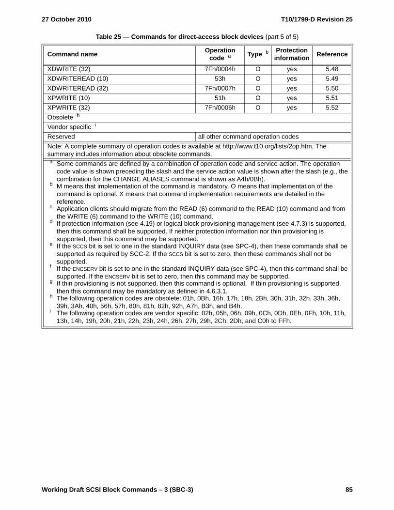
27 October 2010 T10/1799-D Revision 25
Working Draft SCSI Block Commands – 3 (SBC-3) 85
XDWRITE (32) 7Fh/0004h O yes 5.48XDWRITEREAD (10) 53h O yes 5.49XDWRITEREAD (32) 7Fh/0007h O yes 5.50XPWRITE (10) 51h O yes 5.51XPWRITE (32) 7Fh/0006h O yes 5.52Obsolete h
Vendor specific i
Reserved all other command operation codesNote: A complete summary of operation codes is available at http://www.t10.org/lists/2op.htm. The summary includes information about obsolete commands.
Table 25 — Commands for direct-access block devices (part 5 of 5)
Command name Operation code a Type b Protection
information Reference
a Some commands are defined by a combination of operation code and service action. The operation code value is shown preceding the slash and the service action value is shown after the slash (e.g., the combination for the CHANGE ALIASES command is shown as A4h/0Bh).
b M means that implementation of the command is mandatory. O means that implementation of the command is optional. X means that command implementation requirements are detailed in the reference.
c Application clients should migrate from the READ (6) command to the READ (10) command and from the WRITE (6) command to the WRITE (10) command.
d If protection information (see 4.19) or logical block provisioning management (see 4.7.3) is supported, then this command shall be supported. If neither protection information nor thin provisioning is supported, then this command may be supported.
e If the SCCS bit is set to one in the standard INQUIRY data (see SPC-4), then these commands shall be supported as required by SCC-2. If the SCCS bit is set to zero, then these commands shall not be supported.
f If the ENCSERV bit is set to one in the standard INQUIRY data (see SPC-4), then this command shall be supported. If the ENCSERV bit is set to zero, then this command may be supported.
g If thin provisioning is not supported, then this command is optional. If thin provisioning is supported, then this command may be mandatory as defined in 4.6.3.1.
h The following operation codes are obsolete: 01h, 0Bh, 16h, 17h, 18h, 2Bh, 30h, 31h, 32h, 33h, 36h, 39h, 3Ah, 40h, 56h, 57h, 80h, 81h, 82h, 92h, A7h, B3h, and B4h.
i The following operation codes are vendor specific: 02h, 05h, 06h, 09h, 0Ch, 0Dh, 0Eh, 0Fh, 10h, 11h, 13h, 14h, 19h, 20h, 21h, 22h, 23h, 24h, 26h, 27h, 29h, 2Ch, 2Dh, and C0h to FFh.
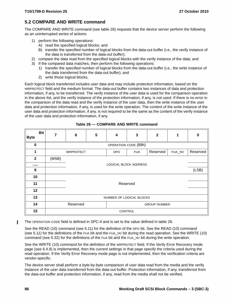
T10/1799-D Revision 25 27 October 2010
86 Working Draft SCSI Block Commands – 3 (SBC-3)
5.2 COMPARE AND WRITE commandThe COMPARE AND WRITE command (see table 26) requests that the device server perform the following as an uninterrupted series of actions:
1) perform the following operations:A) read the specified logical blocks; andB) transfer the specified number of logical blocks from the data-out buffer (i.e., the verify instance of
the data is transferred from the data-out buffer);2) compare the data read from the specified logical blocks with the verify instance of the data; and3) If the compared data matches, then perform the following operations:
1) transfer the specified number of logical blocks from the data-out buffer (i.e., the write instance of the data transferred from the data-out buffer); and
2) write those logical blocks.
Each logical block transferred includes user data and may include protection information, based on the WRPROTECT field and the medium format. The data-out buffer contains two instances of data and protection information, if any, to be transferred. The verify instance of the user data is used for the comparison operation in the above list, and the verify instance of the protection information, if any, is not used. If there is no error in the comparison of the data read and the verify instance of the user data, then the write instance of the user data and protection information, if any, is used for the write operation. The content of the write instance of the user data and protection information, if any, is not required to be the same as the content of the verify instance of the user data and protection information, if any.
The OPERATION CODE field is defined in SPC-4 and is set to the value defined in table 26.
See the READ (10) command (see 5.11) for the definition of the DPO bit. See the READ (10) command (see 5.11) for the definitions of the FUA bit and the FUA_NV bit during the read operation. See the WRITE (10) command (see 5.32) for the definitions of the FUA bit and the FUA_NV bit during the write operation.
See the WRITE (10) command for the definition of the WRPROTECT field. If the Verify Error Recovery mode page (see 6.4.8) is implemented, then the current settings in that page specify the criteria used during the read operation. If the Verify Error Recovery mode page is not implemented, then the verification criteria are vendor-specific.
The device server shall perform a byte-by-byte comparison of user data read from the media and the verify instance of the user data transferred from the data-out buffer. Protection information, if any, transferred from the data-out buffer and protection information, if any, read from the media shall not be verified.
Table 26 — COMPARE AND WRITE command
BitByte 7 6 5 4 3 2 1 0
0 OPERATION CODE (89h)
1 WRPROTECT DPO FUA Reserved FUA_NV Reserved
2 (MSB)LOGICAL BLOCK ADDRESS.....
9 (LSB)
10
Reserved11
12
13 NUMBER OF LOGICAL BLOCKS
14 Reserved GROUP NUMBER
15 CONTROL
27 October 2010 T10/1799-D Revision 25
Working Draft SCSI Block Commands – 3 (SBC-3) 87
If the verify instance of the user data when compared to the user data in the logical block(s) read does not match, then the device server shall terminate the command with CHECK CONDITION status with the sense key set to MISCOMPARE and the additional sense code set to MISCOMPARE DURING VERIFY OPERATION. The offset from the start of the data-out buffer to the first byte of data that did not match shall be returned in the INFORMATION field of the sense data, and the VALID bit shall be set to one. The device server shall check the write instance of the protection information, if any, transferred from the data-out buffer based on the contents of the WRPROTECT field during the write operation as defined in table 85.
The LOGICAL BLOCK ADDRESS field specifies the LBA of the first logical block (see 4.4) accessed for the compare operation and the LBA of the first logical block accessed for the write operation. If the specified LBA exceeds the capacity of the medium, then the device server shall terminate the command with CHECK CONDITION status with the sense key set to ILLEGAL REQUEST and the additional sense code set to LOGICAL BLOCK ADDRESS OUT OF RANGE.
The NUMBER OF LOGICAL BLOCKS field specifies:
a) the number of contiguous logical blocks that shall be read from the media, starting with the logical block specified by the LOGICAL BLOCK ADDRESS field;
b) the number of contiguous logical blocks that shall be transferred from the data-out buffer and compared; and
c) if the compared data matches, then the number of contiguous logical blocks that shall be transferred from the data-out buffer and written to the media, starting with the logical block specified by the LOGICAL BLOCK ADDRESS field.
A NUMBER OF LOGICAL BLOCKS field set to zero specifies that no logical blocks shall be read from media, no data shall be compared, and no logical blocks shall be written to the media. This condition shall not be considered an error.
If the LBA plus the number of logical blocks exceeds the capacity of the medium, then the device server shall terminate the command with CHECK CONDITION status with the sense key set to ILLEGAL REQUEST and the additional sense code set to LOGICAL BLOCK ADDRESS OUT OF RANGE.
If the number of logical blocks exceeds the value in the MAXIMUM COMPARE AND WRITE LENGTH field in the Block Limits VPD page (see 6.5.3), then the device server shall terminate the command with CHECK CONDITION status with the sense key set to ILLEGAL REQUEST and the additional sense code set to INVALID FIELD IN CDB.
See the PRE-FETCH (10) command (see 5.7) for the definition of the GROUP NUMBER field.
The contents of the CONTROL byte are defined in SAM-4.
5.3 FORMAT UNIT command
5.3.1 FORMAT UNIT command overview
The FORMAT UNIT command (see table 27) requests that the device server format the medium into application client accessible logical blocks as specified in the number of logical blocks and logical block length values received in the last mode parameter block descriptor (see 6.4.2) in a MODE SELECT command (see SPC-4). In addition, the device server may certify the medium and create control structures for the management of the medium and defects. The degree that the medium is altered by this command is vendor specific.
If a device server receives a FORMAT UNIT command before receiving a MODE SELECT command with a mode parameter block descriptor, then the device server shall use the number of logical blocks and logical block length at which the logical unit is currently formatted (i.e., no change is made to the number of logical blocks and the logical block length of the logical unit during the format operation).
If any deferred downloaded code has been received as a result of a WRITE BUFFER command (see SPC-4), then that deferred downloaded code shall replace the current operational code.

T10/1799-D Revision 25 27 October 2010
88 Working Draft SCSI Block Commands – 3 (SBC-3)
Before performing the operation specified by this command, the device server shall stop all:
a) enabled power condition timers (see SPC-4):b) timers for enabled background scan operations (see 4.20); andc) timers or counters enabled for device-specific background functions.
After the operation is complete, the device server shall reinitialize and restart all enabled timers and counters for power conditions and background functions.
While performing a format operation, the device server shall terminate all commands except INQUIRY commands, REPORT LUNS commands, and REQUEST SENSE commands with CHECK CONDITION status with the sense key set to NOT READY and the additional sense code set to LOGICAL UNIT NOT READY, FORMAT IN PROGRESS. If the device server receives an INQUIRY command, a REPORT LUNS commands, or a REQUEST SENSE command, then the device server shall process the command. The device server shall return data for an INQUIRY command based on the condition of the SCSI target device before beginning the FORMAT UNIT command (i.e., INQUIRY data shall not change until after successful completion of a format operation). The processing of commands in the task set when a FORMAT UNIT command is received is vendor specific.
The PROGRESS INDICATION field in parameter data returned by the device server in response to a REQUEST SENSE command (see SPC-4) may be used by the application client at any time during a format operation to poll the logical unit’s progress. While a format operation is in progress unless an error has occurred, a device server shall respond to a REQUEST SENSE command by returning parameter data containing sense data with the sense key set to NOT READY and the additional sense code set to LOGICAL UNIT NOT READY, FORMAT IN PROGRESS with the sense key specific bytes set for progress indication (see SPC-4).
The simplest form of the FORMAT UNIT command (i.e., a FORMAT UNIT command with no parameter data) accomplishes medium formatting with little application client control over defect management. The device server implementation determines the degree of defect management that is to be performed. Additional forms of this command increase the application client's control over defect management. The application client may specify:
a) defect list(s) to be used;b) defect locations;c) that logical unit certification be enabled; andd) exception handling in the event that defect lists are not accessible.
Following a successful format operation:
a) if the logical unit is fully provisioned (i.e., the LBPME bit in the READ CAPACITY (16) parameter data is set to zero), then all LBAs are mapped (see 4.7.2);
b) if the logical unit supports logical block provisioning management (i.e., the LBPME bit is set to one), then:A) if the LBPRZ bit in the READ CAPACITY (16) parameter data is set to zero, then each LBA may be
either mapped or unmapped; andB) if the LBPRZ bit is set to one, then each LBA:
a) shall be mapped, if the format operation did not write all zeroes to that LBA (i.e., a read operation specifying that LBA returns user data with at least one bit set to one);
b) shall be unmapped if the format operation wrote all zeroes to all valid LBAs in the logical unit (i.e., for any valid LBA on the logical unit, a read operation returns user data with all bits set to zero); or
c) may be unmapped if the format operation wrote all zeroes to that LBA and the format operation did not write all zeroes to all valid LBAs in the logical unit.

27 October 2010 T10/1799-D Revision 25
Working Draft SCSI Block Commands – 3 (SBC-3) 89
Table 27 defines the FORMAT UNIT command.
The OPERATION CODE field is defined in SPC-4 and is set to the value defined in table 27.
The format protection information (FMTPINFO) field (see table 32) in combination with the PROTECTION FIELD USAGE field (see 5.3.2.2) specifies whether or not the device server enables or disables the use of protection information.
A LONGLIST bit set to zero specifies that the parameter list, if any, contains a short parameter list header as defined in table 30. A LONGLIST bit set to one specifies that the parameter list, if any, contains a long parameter list header as defined in table 31. If the FMTDATA bit is set to zero, then the LONGLIST bit shall be ignored.
A format data (FMTDATA) bit set to zero specifies that no parameter list be transferred from the data-out buffer.
A FMTDATA bit set to one specifies that the FORMAT UNIT parameter list (see table 29) shall be transferred from the data-out buffer. The parameter list consists of a parameter list header, followed by an optional initialization pattern descriptor, followed by an optional defect list.
If the FMTDATA bit is set to zero and the FMTPINFO field is not set to zero, then the device server shall terminate the command with CHECK CONDITION status with the sense key set to ILLEGAL REQUEST and the additional sense code set to INVALID FIELD IN CDB.
Following a successful format operation, the PROT_EN bit and the P_TYPE field in the READ CAPACITY (16) parameter data (see 5.16.2) indicate the type of protection currently in effect on the logical unit.
If protection information is written during a format operation (i.e., the FMTPINFO field is set to a value greater than zero), then protection information shall be written to a default value of FFFF_FFFF_FFFF_FFFFh.
A complete list (CMPLST) bit set to zero specifies that the defect list included in the FORMAT UNIT parameter list shall be used in an addition to the existing list of defects. As a result, the device server shall construct a new GLIST (see 4.11) that contains:
a) the existing GLIST;b) the DLIST, if it is sent by the application client; andc) the CLIST, if certification is enabled (i.e., the device server may add any defects it detects during the
format operation).
A CMPLST bit set to one specifies that the defect list included in the FORMAT UNIT parameter list is a complete list of defects. Any existing defect list except the PLIST shall be ignored by the device server. As a result, the device server shall construct a new GLIST (see 4.11) that contains:
a) the DLIST, if it is sent by the application client; andb) the CLIST, if certification is enabled (i.e., the device server may add any defects it detects during the
format operation).
If the FMTDATA bit is set to zero, then the CMPLST bit shall be ignored.
Table 27 — FORMAT UNIT command
BitByte 7 6 5 4 3 2 1 0
0 OPERATION CODE (04h)
1 FMTPINFO LONGLIST FMTDATA CMPLST DEFECT LIST FORMAT
2 vendor specific
3Obsolete
4
5 CONTROL

T10/1799-D Revision 25 27 October 2010
90 Working Draft SCSI Block Commands – 3 (SBC-3)
If the FMTDATA bit is set to one, then the DEFECT LIST FORMAT field specifies the format of the address descriptors in the defect list (see table 28).
The contents of the CONTROL byte are defined in SAM-4.
Table 28 — FORMAT UNIT command address descriptor usage
Field in the FORMAT UNIT CDB DEFECT LIST LENGTH field in the
parameter list header
Type a Comments fFMTDATA CMPLST
DEFECT LIST
FORMAT
0 any 000b Not available M vendor specific defect information
1
0000b (short block)
ZeroO See b and d
1 O See c and e
0Nonzero
O See c and d
1 O See b and e
1
0011b (long block)
ZeroO See b and d
1 O See b and e
0Nonzero
O See c and d
1 O See c and e
1
0100b (bytes from
index)
ZeroO See b and d
1 O See b and e
0Nonzero
O See c and d
1 O See c and e
1
0101b
(physical sector)
ZeroO See b and d
1 O See b and e
0Nonzero
O See c and d
1 O See c and e
10 110b
(vendor-specific)
vendor specificO
1 O
All others Reserved.a M = implementation is mandatory. O = implementation is optional.b No DLIST is included in the parameter list.c A DLIST is included in the parameter list. The device server shall add the DLIST defects to the new
GLIST.d The device server shall add existing GLIST defects to the new GLIST (i.e., use the existing GLIST).e The device server shall not add existing GLIST defects to the new GLIST (i.e., discard the existing
GLIST).f All the options described in this table cause a new GLIST to be created during processing of the
FORMAT UNIT command as described in the text.

27 October 2010 T10/1799-D Revision 25
Working Draft SCSI Block Commands – 3 (SBC-3) 91
5.3.2 FORMAT UNIT parameter list
5.3.2.1 FORMAT UNIT parameter list overview
Table 29 defines the FORMAT UNIT parameter list.
The parameter list header is defined in 5.3.2.2.
The initialization pattern descriptor, if any, is defined in 5.3.2.3.
The defect list, if any, contains address descriptors (see 5.3.2.4) each specifying a location on the medium that the device server shall exclude from the application client accessible part. This is called the DLIST (see 4.11). The device server shall maintain the current logical block to physical block alignment (see 4.6) for logical blocks not specified in the defect list.
5.3.2.2 Parameter list header
The parameter list headers (see table 30 and table 31) provide several optional format control parameters. Device servers that implement these headers provide the application client additional control over the use of the four defect sources, and the format operation. If the application client attempts to select any function not implemented by the device server, then the device server shall terminate the command with CHECK CONDITION status with the sense key set to ILLEGAL REQUEST and the additional sense code set to INVALID FIELD IN PARAMETER LIST.
If the LONGLIST bit is set to zero in the FORMAT UNIT CDB, then the short parameter list header (see table 30) is used.
Table 29 — FORMAT UNIT parameter list
BitByte 7 6 5 4 3 2 1 0
0 to 3 or0 to 7 Parameter list header (see table 30 or table 31 in 5.3.2.2)
Initialization pattern descriptor (if any)(see table 33 in 5.3.2.3)
Defect list (if any)
Table 30 — Short parameter list header
BitByte 7 6 5 4 3 2 1 0
0 Reserved PROTECTION FIELD USAGE
1 FOV DPRY DCRT STPF IP Obsolete IMMEDVendor-specific
2 (MSB)DEFECT LIST LENGTH
3 (LSB)
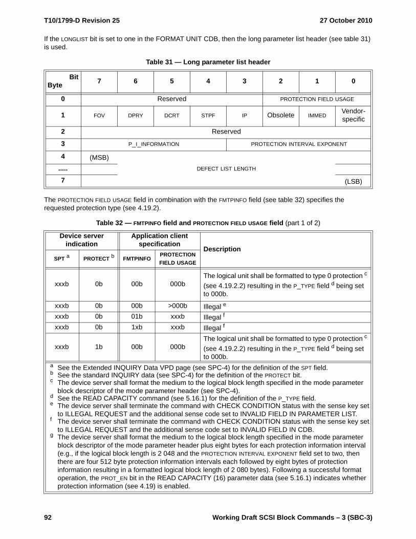
T10/1799-D Revision 25 27 October 2010
92 Working Draft SCSI Block Commands – 3 (SBC-3)
If the LONGLIST bit is set to one in the FORMAT UNIT CDB, then the long parameter list header (see table 31) is used.
The PROTECTION FIELD USAGE field in combination with the FMTPINFO field (see table 32) specifies the requested protection type (see 4.19.2).
Table 31 — Long parameter list header
BitByte 7 6 5 4 3 2 1 0
0 Reserved PROTECTION FIELD USAGE
1 FOV DPRY DCRT STPF IP Obsolete IMMEDVendor-specific
2 Reserved
3 P_I_INFORMATION PROTECTION INTERVAL EXPONENT
4 (MSB)DEFECT LIST LENGTH.....
7 (LSB)
Table 32 — FMTPINFO field and PROTECTION FIELD USAGE field (part 1 of 2)
Device server indication
Application client specification
DescriptionSPT a PROTECT b FMTPINFO
PROTECTION FIELD USAGE
xxxb 0b 00b 000bThe logical unit shall be formatted to type 0 protection c (see 4.19.2.2) resulting in the P_TYPE field d being set to 000b.
xxxb 0b 00b >000b Illegal e
xxxb 0b 01b xxxb Illegal f
xxxb 0b 1xb xxxb Illegal f
xxxb 1b 00b 000bThe logical unit shall be formatted to type 0 protection c (see 4.19.2.2) resulting in the P_TYPE field d being set to 000b.
a See the Extended INQUIRY Data VPD page (see SPC-4) for the definition of the SPT field.b See the standard INQUIRY data (see SPC-4) for the definition of the PROTECT bit.c The device server shall format the medium to the logical block length specified in the mode parameter
block descriptor of the mode parameter header (see SPC-4). d See the READ CAPACITY command (see 5.16.1) for the definition of the P_TYPE field.e The device server shall terminate the command with CHECK CONDITION status with the sense key set
to ILLEGAL REQUEST and the additional sense code set to INVALID FIELD IN PARAMETER LIST.f The device server shall terminate the command with CHECK CONDITION status with the sense key set
to ILLEGAL REQUEST and the additional sense code set to INVALID FIELD IN CDB.g The device server shall format the medium to the logical block length specified in the mode parameter
block descriptor of the mode parameter header plus eight bytes for each protection information interval (e.g., if the logical block length is 2 048 and the PROTECTION INTERVAL EXPONENT field set to two, then there are four 512 byte protection information intervals each followed by eight bytes of protection information resulting in a formatted logical block length of 2 080 bytes). Following a successful format operation, the PROT_EN bit in the READ CAPACITY (16) parameter data (see 5.16.1) indicates whether protection information (see 4.19) is enabled.

27 October 2010 T10/1799-D Revision 25
Working Draft SCSI Block Commands – 3 (SBC-3) 93
A format options valid (FOV) bit set to zero specifies that the device server shall use its default settings for the DPRY bit, the DCRT bit, the STPF bit, and IP bit. If the FOV bit is set to zero, then the application client shall set these bits to zero. If the FOV bit is set to zero, and any of the other bits listed in this paragraph are not set to
xxxb 1b 00b >000b Illegal e
xxxb 1b 01b xxxb Illegal f
000b001b011b111b
1b 10b 000bThe logical unit shall be formatted to type 1 protection g (see 4.19.2.3) resulting in the P_TYPE field d being set to 000b.
000b001b011b111b
1b 10b >000b Illegal e
000b 1b 11b xxxb Illegal f
001b010b101b111b
1b 11b 000bThe logical unit shall be formatted to type 2 protection g (see 4.19.2.4) resulting in the P_TYPE field d being set to 001b.
001b010b 1b 11b >000b Illegal e
011b100b 1b 11b 000b Illegal e
011b100b101b111b
1b 11 001bThe logical unit shall be formatted to type 3 protection. g (see 4.19.2.5) resulting in the P_TYPE field d being set to 010b.
011b100b101b111b
1b 11b >001b Illegal e
110b 1b 11b xxxb Reserved
Table 32 — FMTPINFO field and PROTECTION FIELD USAGE field (part 2 of 2)
Device server indication
Application client specification
DescriptionSPT a PROTECT b FMTPINFO
PROTECTION FIELD USAGE
a See the Extended INQUIRY Data VPD page (see SPC-4) for the definition of the SPT field.b See the standard INQUIRY data (see SPC-4) for the definition of the PROTECT bit.c The device server shall format the medium to the logical block length specified in the mode parameter
block descriptor of the mode parameter header (see SPC-4). d See the READ CAPACITY command (see 5.16.1) for the definition of the P_TYPE field.e The device server shall terminate the command with CHECK CONDITION status with the sense key set
to ILLEGAL REQUEST and the additional sense code set to INVALID FIELD IN PARAMETER LIST.f The device server shall terminate the command with CHECK CONDITION status with the sense key set
to ILLEGAL REQUEST and the additional sense code set to INVALID FIELD IN CDB.g The device server shall format the medium to the logical block length specified in the mode parameter
block descriptor of the mode parameter header plus eight bytes for each protection information interval (e.g., if the logical block length is 2 048 and the PROTECTION INTERVAL EXPONENT field set to two, then there are four 512 byte protection information intervals each followed by eight bytes of protection information resulting in a formatted logical block length of 2 080 bytes). Following a successful format operation, the PROT_EN bit in the READ CAPACITY (16) parameter data (see 5.16.1) indicates whether protection information (see 4.19) is enabled.

T10/1799-D Revision 25 27 October 2010
94 Working Draft SCSI Block Commands – 3 (SBC-3)
zero, then the device server shall terminate the command with CHECK CONDITION status with the sense key set to ILLEGAL REQUEST and the additional sense code set to INVALID FIELD IN PARAMETER LIST.
A FOV bit set to one specifies that the device server shall examine the values of the DPRY, DCRT, STPF, and IP bits. When the FOV bit is set to one, the DPRY, DCRT, STPF, and IP bits are defined as follows.
A disable primary (DPRY) bit set to zero specifies that the device server shall not use parts of the medium identified as defective in the PLIST for application client accessible logical blocks. If the device server is not able to locate the PLIST or it is not able to determine whether a PLIST exists, then the device server shall take the action specified by the STPF bit.
A DPRY bit set to one specifies that the device server shall not use the PLIST to identify defective areas of the medium. The PLIST shall not be deleted.
A disable certification (DCRT) bit set to zero specifies that the device server shall perform a vendor specific medium certification operation to generate a CLIST. A DCRT bit set to one specifies that the device server shall not perform any vendor specific medium certification process or format verification operation.
The stop format (STPF) bit controls the behavior of the device server if one of the following events occurs:
a) The device server has been requested to use the PLIST (i.e., the DPRY bit is set to zero) or the GLIST (i.e., the CMPLST bit is set to zero) and the device server is not able to locate the list or determine whether the list exists; or
b) The device server has been requested to use the PLIST (i.e., the DPRY bit is set to zero) or the GLIST (i.e., the CMPLST bit is set to zero), and the device server encounters an error while accessing the defect list.
A STPF bit set to zero specifies that, if one or both of these events occurs, the device server shall continue to process the FORMAT UNIT command. The device server shall terminate the FORMAT UNIT command with CHECK CONDITION status at the completion of the command with the sense key set to RECOVERED ERROR and the additional sense code set to either DEFECT LIST NOT FOUND if the condition described in item a) occurred, or DEFECT LIST ERROR if the condition described in item b) occurred.
A STPF bit set to one specifies that, if one or both of these events occurs, then the device server shall terminate the FORMAT UNIT command with CHECK CONDITION status and the sense key shall be set to MEDIUM ERROR with the additional sense code set to either DEFECT LIST NOT FOUND if the condition described in item a) occurred, or DEFECT LIST ERROR if the condition described in item b) occurred.
NOTE 8 - The use of the FMTDATA bit, the CMPLST bit, and the parameter list header allow the application client to control the source of the defect lists used by the FORMAT UNIT command. Setting the DEFECT LIST LENGTH field to zero allows the application client to control the use of PLIST and CLIST without having to specify a DLIST.
An initialization pattern (IP) bit set to zero specifies that an initialization pattern descriptor is not included and that the device server shall use its default initialization pattern. An IP bit set to one specifies that an initialization pattern descriptor (see 5.3.2.3) is included in the FORMAT UNIT parameter list following the parameter list header.
If the IP bit is set to one, then the device server in a logical unit that supports logical block provisioning management may terminate the FORMAT UNIT command with CHECK CONDITION status with the sense key set to ILLEGAL REQUEST and the additional sense code set to INVALID FIELD IN PARAMETER LIST.
An immediate (IMMED) bit set to zero specifies that the device server shall return status after the format operation has completed. An IMMED bit value set to one specifies that the device server shall return status after the entire parameter list has been transferred.
The P_I_INFORMATION field shall be set to zero.
For a type 1 protection information request, if the PROTECTION INTERVAL EXPONENT field is not set to zero, then the device server shall terminate the command with CHECK CONDITION status with the sense key set to ILLEGAL REQUEST and the additional sense code set to INVALID FIELD IN PARAMETER LIST.

27 October 2010 T10/1799-D Revision 25
Working Draft SCSI Block Commands – 3 (SBC-3) 95
For a type 2 protection or a type 3 protection format request, the protection interval exponent determines the length of user data to be sent before protection information is transferred (i.e., the protection information interval).
The protection information interval is calculated as follows:
protection information interval = logical block length / 2(protection interval exponent)
where:
logical block length is the length in bytes of a logical block as specified in the mode parameter block descriptor (see 6.4.2.1)
protection interval exponent is the contents of the PROTECTION INTERVAL EXPONENT field
If the protection information interval calculates to a value that is not an even number (e.g., 520/23 = 65) or not a whole number (e.g., 520/24 = 32.5 and 520/210 = 0.508), then the device server shall terminate the command with CHECK CONDITION status with the sense key set to ILLEGAL REQUEST and the additional sense code set to INVALID FIELD IN PARAMETER LIST.
The DEFECT LIST LENGTH field specifies the total length in bytes of the defect list (i.e., the address descriptors) that follows and does not include the initialization pattern descriptor, if any. The formats for the address descriptor(s) are shown in 5.3.2.4.
Short block format address descriptors and long block format address descriptors should be in ascending order. Bytes from index format address descriptors and physical sector format address descriptors shall be in ascending order. More than one physical or logical block may be affected by each address descriptor. If the address descriptors are not in the required order, then the device server shall terminate the command with CHECK CONDITION status with the sense key set to ILLEGAL REQUEST and the additional sense code set to INVALID FIELD IN PARAMETER LIST.
5.3.2.3 Initialization pattern descriptor
The initialization pattern descriptor specifies that the device server initialize logical blocks to a specified pattern. The initialization pattern descriptor (see table 33) is sent to the device server as part of the FORMAT UNIT parameter list.
Table 33 — Initialization pattern descriptor
BitByte 7 6 5 4 3 2 1 0
0 IP MODIFIER SI Reserved
1 INITIALIZATION PATTERN TYPE
2 (MSB)INITIALIZATION PATTERN LENGTH (n - 3)
3 (LSB)
4INITIALIZATION PATTERN.....
n

T10/1799-D Revision 25 27 October 2010
96 Working Draft SCSI Block Commands – 3 (SBC-3)
The initialization pattern modifier (IP MODIFIER) field (see table 34) specifies the type and location of a header that modifies the initialization pattern.
A security initialize (SI) bit set to one specifies that the device server shall attempt to write the initialization pattern to all areas of the medium including those that may have been reassigned (i.e., are in a defect list). An SI bit set to one shall take precedence over any other FORMAT UNIT CDB field. The initialization pattern shall be written using a security erasure write technique. Application clients may choose to use this command multiple times to fully erase the previous data. Such security erasure write technique procedures are outside the scope of this standard. The exact requirements placed on the security erasure write technique are vendor specific. The intent of the security erasure write is to render any previous user data unrecoverable by any analog or digital technique.
An SI bit set to zero specifies that the device server shall initialize the application client accessible part of the medium. The device server is not required to initialize other areas of the medium. However, the device server shall format the medium as defined in the FORMAT UNIT command.
When the SI bit is set to one, the device server need not write the initialization pattern over the header and other parts of the medium not previously accessible to the application client. If the device server is unable to write over any part of the medium that is currently accessible to the application client or may be made accessible to the application client in the future (e.g., by clearing the defect list), then the device server shall terminate the command with CHECK CONDITION status with the sense key set to MEDIUM ERROR and the additional sense code set to the appropriate value for the condition. The device server shall attempt to rewrite all remaining parts of the medium even if some parts are not able to be rewritten.
Table 34 — Initialization pattern modifier (IP MODIFIER) field
Code Description
00b No header. The device server shall not modify the initialization pattern.
01b
The device server shall overwrite the initialization pattern to write the LBA in the first four bytes of each logical block. The LBA shall be written with the most significant byte first. If the LBA is larger than four bytes, then the least significant four bytes shall be written ending with the least significant byte.
10b
The device server shall overwrite the initialization pattern to write the LBA in the first four bytes of each physical block contained within the logical block. The lowest numbered logical block or part thereof that occurs within the physical block is used. The LBA shall be written with the most significant byte first. If the LBA is larger than four bytes, then the least significant four bytes shall be written ending with the least significant byte.
11b Reserved.

27 October 2010 T10/1799-D Revision 25
Working Draft SCSI Block Commands – 3 (SBC-3) 97
The INITIALIZATION PATTERN TYPE field (see table 35) specifies the type of pattern the device server shall use to initialize each logical block within the application client accessible part of the medium. All bytes within a logical block shall be written with the initialization pattern. The initialization pattern is modified by the IP MODIFIER field as described in table 34.
The INITIALIZATION PATTERN LENGTH field specifies the number of bytes contained in the INITIALIZATION PATTERN field. If the initialization pattern length exceeds the current logical block length, then the device server shall terminate the command with CHECK CONDITION status with the sense key set to ILLEGAL REQUEST and the additional sense code set to INVALID FIELD IN PARAMETER LIST.
The INITIALIZATION PATTERN field specifies the initialization pattern. The initialization pattern is modified by the IP MODIFIER field.
5.3.2.4 Address descriptor formats
5.3.2.4.1 Address descriptor formats overview
This subclause describes the address descriptor formats (see table 36) used for:
a) the FORMAT UNIT command;b) the READ DEFECT DATA (10) command (see 5.17) and the READ DEFECT DATA (12) command
(see 5.18); andc) the Translate Address Input diagnostic page (see 6.2.2) and the Translate Address Output diagnostic
page (see 6.2.3) for the SEND DIAGNOSTIC command (see SPC-4) and the RECEIVE DIAGNOSTIC RESULTS command (see SPC-4).
The format type of an address descriptor is specified with:
a) the DEFECT LIST FORMAT field in the CDB for the FORMAT UNIT command and the READ DEFECT DATA commands;
b) the SUPPLIED FORMAT field for the Translate Address diagnostic pages; orc) the TRANSLATE FORMAT field for the Translate Address diagnostic pages.
Table 35 — INITIALIZATION PATTERN TYPE field
Code Description
00h Use a default initialization pattern a
01h Repeat the pattern specified in the INITIALIZATION PATTERN field as required to fill the logical block b
02h to 7Fh Reserved
80h to FFh vendor specifica If the INITIALIZATION PATTERN LENGTH field is not set to zero, then the device server shall terminate the
command with CHECK CONDITION status with the sense key set to ILLEGAL REQUEST and the additional sense code set to INVALID FIELD IN PARAMETER LIST.
b If the INITIALIZATION PATTERN LENGTH field is set to zero, then the device server shall terminate the command with CHECK CONDITION status with the sense key set to ILLEGAL REQUEST and the additional sense code set to INVALID FIELD IN PARAMETER LIST.

T10/1799-D Revision 25 27 October 2010
98 Working Draft SCSI Block Commands – 3 (SBC-3)
Table 36 defines the types of address descriptors.
5.3.2.4.2 Short block format address descriptor
A format type of 000b specifies the short block format address descriptor defined in table 37.
For the FORMAT UNIT command, the SHORT BLOCK ADDRESS field contains the four-byte LBA of a defect. If multiple logical blocks are contained within a physical block, then the device server may consider logical blocks in addition to the one specified by this descriptor as containing defects.
For the READ DEFECT DATA commands, the SHORT BLOCK ADDRESS field contains a vendor specific four-byte value.
For the Translate Address diagnostic pages, the SHORT BLOCK ADDRESS field contains a four-byte LBA or a vendor specific four-byte value that is greater than the capacity of the medium.
5.3.2.4.3 Long block format address descriptor
A format type of 011b specifies the long block format address descriptor defined in table 38.
For the FORMAT UNIT command, the LONG BLOCK ADDRESS field contains the eight-byte LBA of a defect. If multiple logical blocks are contained within a physical block, then the device server may consider logical blocks in addition to the one specified by this descriptor as containing defects.
For the READ DEFECT DATA commands, the LONG BLOCK ADDRESS field contains a vendor specific eight-byte value.
Table 36 — Address descriptor formats
Format type Description Reference
000b Short block format address descriptor 5.3.2.4.2
011b Long block format address descriptor 5.3.2.4.3
100b Bytes from index format address descriptor 5.3.2.4.4
101b Physical sector format address descriptor 5.3.2.4.5
110b vendor specific
All others Reserved
Table 37 — Short block format address descriptor (000b)
BitByte 7 6 5 4 3 2 1 0
0 (MSB)
SHORT BLOCK ADDRESS.....3 (LSB)
Table 38 — Long block format address descriptor (011b)
BitByte 7 6 5 4 3 2 1 0
0 (MSB)LONG BLOCK ADDRESS.....
7 (LSB)
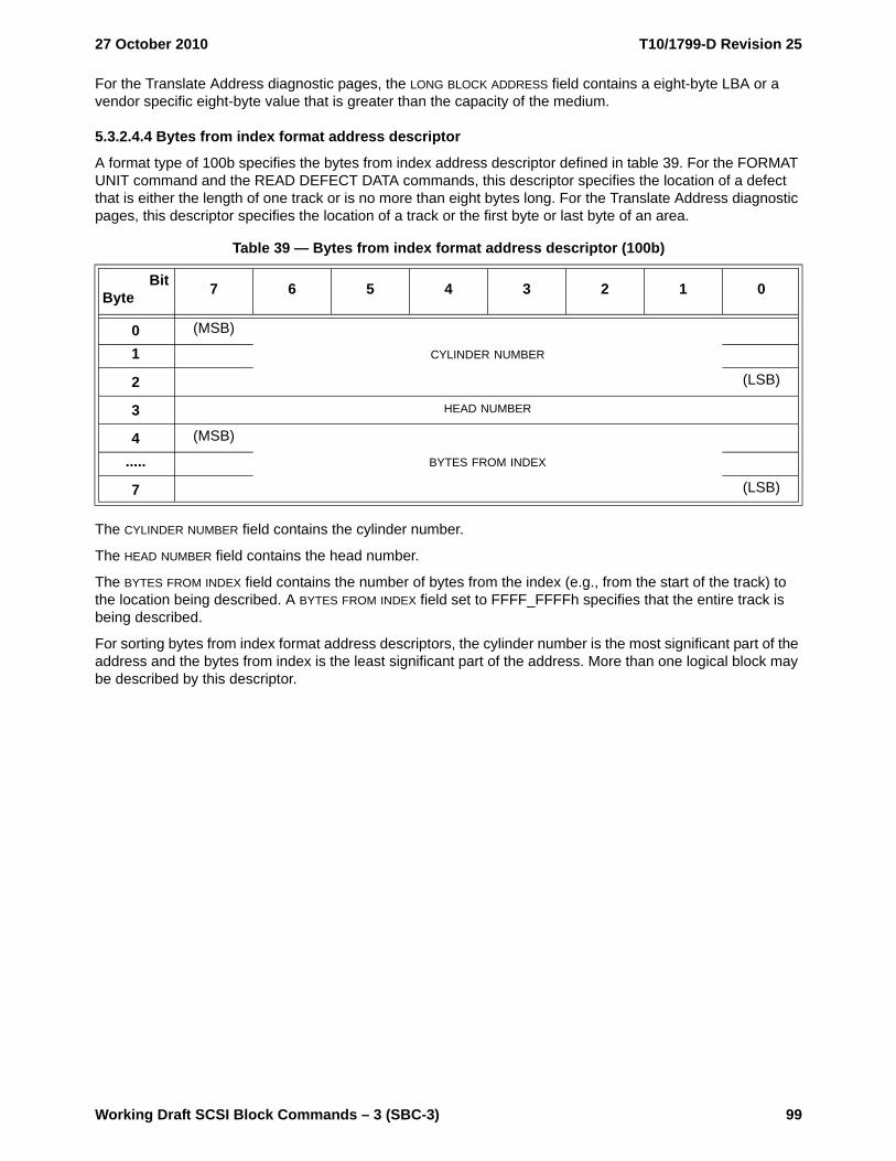
27 October 2010 T10/1799-D Revision 25
Working Draft SCSI Block Commands – 3 (SBC-3) 99
For the Translate Address diagnostic pages, the LONG BLOCK ADDRESS field contains a eight-byte LBA or a vendor specific eight-byte value that is greater than the capacity of the medium.
5.3.2.4.4 Bytes from index format address descriptor
A format type of 100b specifies the bytes from index address descriptor defined in table 39. For the FORMAT UNIT command and the READ DEFECT DATA commands, this descriptor specifies the location of a defect that is either the length of one track or is no more than eight bytes long. For the Translate Address diagnostic pages, this descriptor specifies the location of a track or the first byte or last byte of an area.
The CYLINDER NUMBER field contains the cylinder number.
The HEAD NUMBER field contains the head number.
The BYTES FROM INDEX field contains the number of bytes from the index (e.g., from the start of the track) to the location being described. A BYTES FROM INDEX field set to FFFF_FFFFh specifies that the entire track is being described.
For sorting bytes from index format address descriptors, the cylinder number is the most significant part of the address and the bytes from index is the least significant part of the address. More than one logical block may be described by this descriptor.
Table 39 — Bytes from index format address descriptor (100b)
BitByte 7 6 5 4 3 2 1 0
0 (MSB)
CYLINDER NUMBER1
2 (LSB)
3 HEAD NUMBER
4 (MSB)
BYTES FROM INDEX.....
7 (LSB)

T10/1799-D Revision 25 27 October 2010
100 Working Draft SCSI Block Commands – 3 (SBC-3)
5.3.2.4.5 Physical sector format address descriptor
A format type of 101b specifies the physical sector address descriptor defined in table 40. For the FORMAT UNIT command and the READ DEFECT DATA commands, this descriptor specifies the location of a defect that is either the length of one track or the length of one sector. For the Translate Address diagnostic pages, this descriptor specifies the location of a track or a sector.
The CYLINDER NUMBER field contains the cylinder number.
The HEAD NUMBER field contains the head number.
The SECTOR NUMBER field contains the sector number. A SECTOR NUMBER field set to FFFF_FFFFh specifies that the entire track is being described.
For sorting physical sector format address descriptors, the cylinder number is the most significant part of the address and the sector number is the least significant part of the address. More than one logical block may be described by this descriptor.
Table 40 — Physical sector format address descriptor (101b)
BitByte 7 6 5 4 3 2 1 0
0 (MSB)
CYLINDER NUMBER1
2 (LSB)
3 HEAD NUMBER
4 (MSB)
SECTOR NUMBER.....
7 (LSB)

27 October 2010 T10/1799-D Revision 25
Working Draft SCSI Block Commands – 3 (SBC-3) 101
5.4 GET LBA STATUS command
5.4.1 GET LBA STATUS command overview
The GET LBA STATUS command (see table 41) requests that the device server transfer parameter data describing the provisioning status for the specified logical block addresses to the data-in buffer. This command should be implemented by device servers supporting logical block provisioning management (see 4.7.3).
The device server may or may not process this command as an uninterrupted sequence of actions (e.g., if concurrent map and/or unmap operations are occurring the returned parameter data may be inconsistent or out of date).
The OPERATION CODE field is defined in SPC-4 and is set to the value defined in table 41.
The SERVICE ACTION field is defined in SPC-4 and shall be set to the value defined in table 41.
The STARTING LOGICAL BLOCK ADDRESS field specifies the LBA of the first logical block addressed by this command. If the specified LBA is not within the capacity of the medium (see 4.5), then the device server shall terminate the command with CHECK CONDITION status with the sense key set to ILLEGAL REQUEST and the additional sense code set to LOGICAL BLOCK ADDRESS OUT OF RANGE.
The ALLOCATION LENGTH field specifies the maximum number of bytes that the application client has allocated for returned parameter data. An allocation length of zero indicates that no data shall be transferred. This condition shall not be considered an error. The device server shall terminate transfers to the data-in buffer when the number of bytes specified by the ALLOCATION LENGTH field have been transferred or when all available data has been transferred, whichever is less. The contents of the eight-byte parameter data header shall not be altered to reflect the truncation, if any, that results from an insufficient allocation length.
The contents of the CONTROL byte are defined in SAM-4.
Table 41 — GET LBA STATUS command
BitByte 7 6 5 4 3 2 1 0
0 OPERATION CODE (9Eh)
1 Reserved SERVICE ACTION (12h)
2 (MSB)
STARTING LOGICAL BLOCK ADDRESS.....
9 (LSB)
10 (MSB)
ALLOCATION LENGTH.....
13 (LSB)
14 Reserved
15 CONTROL

T10/1799-D Revision 25 27 October 2010
102 Working Draft SCSI Block Commands – 3 (SBC-3)
5.4.2 GET LBA STATUS parameter data
5.4.2.1 GET LBA STATUS parameter data overview
The GET LBA STATUS parameter data (see table 42) contains an eight-byte header followed by one or more LBA status descriptors.
The PARAMETER DATA LENGTH field indicates the number of bytes of parameter data that follow. The value in the PARAMETER DATA LENGTH field shall be:
a) at least 20 (i.e., the available parameter data shall contain at least one LBA status descriptor); andb) four added to a multiple of 16 (i.e., the available parameter data shall end on a boundary between
LBA Status descriptors).
Due to processing considerations outside the scope of this standard, two GET LBA STATUS commands with identical values in all CDB fields may result in two different values in the PARAMETER DATA LENGTH field.
The relationship between the PARAMETER DATA LENGTH field and the ALLOCATION LENGTH field in the CDB is defined in SPC-4.
Table 42 — GET LBA STATUS parameter data
BitByte 7 6 5 4 3 2 1 0
0 (MSB)
PARAMETER DATA LENGTH (n-3).....
3 (LSB)
4
Reserved.....
7
LBA Status Descriptors
8
LBA Status Descriptor (first) (see 5.4.2.2).....
23
.....
n-15
LBA Status Descriptor (last) (see 5.4.2.2).....
n
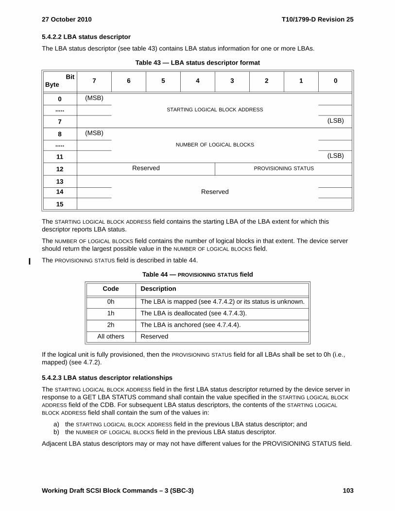
27 October 2010 T10/1799-D Revision 25
Working Draft SCSI Block Commands – 3 (SBC-3) 103
5.4.2.2 LBA status descriptor
The LBA status descriptor (see table 43) contains LBA status information for one or more LBAs.
The STARTING LOGICAL BLOCK ADDRESS field contains the starting LBA of the LBA extent for which this descriptor reports LBA status.
The NUMBER OF LOGICAL BLOCKS field contains the number of logical blocks in that extent. The device server should return the largest possible value in the NUMBER OF LOGICAL BLOCKS field.
The PROVISIONING STATUS field is described in table 44.
If the logical unit is fully provisioned, then the PROVISIONING STATUS field for all LBAs shall be set to 0h (i.e., mapped) (see 4.7.2).
5.4.2.3 LBA status descriptor relationships
The STARTING LOGICAL BLOCK ADDRESS field in the first LBA status descriptor returned by the device server in response to a GET LBA STATUS command shall contain the value specified in the STARTING LOGICAL BLOCK ADDRESS field of the CDB. For subsequent LBA status descriptors, the contents of the STARTING LOGICAL BLOCK ADDRESS field shall contain the sum of the values in:
a) the STARTING LOGICAL BLOCK ADDRESS field in the previous LBA status descriptor; andb) the NUMBER OF LOGICAL BLOCKS field in the previous LBA status descriptor.
Adjacent LBA status descriptors may or may not have different values for the PROVISIONING STATUS field.
Table 43 — LBA status descriptor format
BitByte 7 6 5 4 3 2 1 0
0 (MSB)
STARTING LOGICAL BLOCK ADDRESS.....
7 (LSB)
8 (MSB)
NUMBER OF LOGICAL BLOCKS.....
11 (LSB)
12 Reserved PROVISIONING STATUS
13Reserved14
15
Table 44 — PROVISIONING STATUS field
Code Description
0h The LBA is mapped (see 4.7.4.2) or its status is unknown.
1h The LBA is deallocated (see 4.7.4.3).
2h The LBA is anchored (see 4.7.4.4).
All others Reserved

T10/1799-D Revision 25 27 October 2010
104 Working Draft SCSI Block Commands – 3 (SBC-3)
5.5 ORWRITE (16) commandThe ORWRITE (16) command (see table 45) requests that the device server perform a set operation (see 4.26.4).
Each logical block includes user data and may include protection information, based on the ORPROTECT field and the medium format.
The OPERATION CODE field is defined in SPC-4 and is set to the value defined in table 45.
See the WRITE (10) command (see 5.32) for the definitions of the FUA bit and the FUA_NV bit. See the READ (10) command (see 5.11) for the definition of the DPO bit. See the PRE-FETCH (10) command (see 5.7) for the definition of the LOGICAL BLOCK ADDRESS field. See the PRE-FETCH (10) command (see 5.7) and 4.20 for the definition of the GROUP NUMBER field.
The TRANSFER LENGTH field specifies the number of contiguous logical blocks of data that are read, transferred from the data-out buffer, and ORed into a bitmap buffer (see 3.1.7), starting with the logical block specified by the LOGICAL BLOCK ADDRESS field. If the logical block address plus the transfer length exceeds the capacity of the medium, then the device server shall terminate the command with CHECK CONDITION status with the sense key set to ILLEGAL REQUEST and the additional sense code set to LOGICAL BLOCK ADDRESS OUT OF RANGE. The TRANSFER LENGTH field is constrained by the MAXIMUM TRANSFER LENGTH field in the Block Limits VPD page (see 6.5.3).
The contents of the CONTROL byte are defined in SAM-4.
The device server shall:
a) check protection information read from the medium based on the ORPROTECT field as described in table 46; and
b) check protection information transferred from the data-out buffer based on the ORPROTECT field as described in table 47.
The order of the user data and protection information checks and comparisons is vendor specific.
Table 45 — ORWRITE (16) command
BitByte 7 6 5 4 3 2 1 0
0 OPERATION CODE (8Bh)
1 ORPROTECT DPO FUA Reserved FUA_NV Reserved
2 (MSB)
LOGICAL BLOCK ADDRESS.....9 (LSB)
10 (MSB)
TRANSFER LENGTH.....13 (LSB)
14 Reserved GROUP NUMBER
15 CONTROL

27 October 2010 T10/1799-D Revision 25
Working Draft SCSI Block Commands – 3 (SBC-3) 105
The device server shall check the protection information read from the medium based on the ORPROTECT field as described in table 46. All footnotes for table 46 are at the end of the table.
Table 46 — ORPROTECT field - checking protection information read from the medium (part 1 of 3)
Code
Logical unit formatted with
protection information
Field in protection
information g
Extended INQUIRY Data VPD page bit
value fIf check fails d e, additional sense code
000bYes i j
LOGICAL BLOCK GUARD
GRD_CHK = 1 LOGICAL BLOCK GUARD CHECK FAILED
GRD_CHK = 0 No check performedLOGICAL BLOCK
APPLICATION TAG
APP_CHK = 1 c LOGICAL BLOCK APPLICATION TAG CHECK FAILED
APP_CHK = 0 No check performed
LOGICAL BLOCK
REFERENCE TAG
REF_CHK = 1 h LOGICAL BLOCK REFERENCE TAG CHECK FAILED
REF_CHK = 0 No check performed
No No protection information on the medium to check. Only user data is checked.
001b101b b
Yes
LOGICAL BLOCK GUARD
GRD_CHK = 1 LOGICAL BLOCK GUARD CHECK FAILED
GRD_CHK = 0 No check performedLOGICAL BLOCK
APPLICATION TAG
APP_CHK = 1 c LOGICAL BLOCK APPLICATION TAG CHECK FAILED
APP_CHK = 0 No check performed
LOGICAL BLOCK
REFERENCE TAG
REF_CHK = 1 h LOGICAL BLOCK REFERENCE TAG CHECK FAILED
REF_CHK = 0 No check performed
No Error condition a
010b bYes
LOGICAL BLOCK GUARD
No check performed
LOGICAL BLOCK
APPLICATION TAG
APP_CHK = 1 c LOGICAL BLOCK APPLICATION TAG CHECK FAILED
APP_CHK = 0 No check performed
LOGICAL BLOCK
REFERENCE TAG
REF_CHK = 1 h LOGICAL BLOCK REFERENCE TAG CHECK FAILED
REF_CHK = 0 No check performed
No Error condition a

T10/1799-D Revision 25 27 October 2010
106 Working Draft SCSI Block Commands – 3 (SBC-3)
011b bYes
LOGICAL BLOCK GUARD
No check performed
LOGICAL BLOCK
APPLICATION TAG
No check performed
LOGICAL BLOCK
REFERENCE TAG
No check performed
No Error condition a
100b bYes
LOGICAL BLOCK GUARD
GRD_CHK = 1 LOGICAL BLOCK GUARD CHECK FAILED
GRD_CHK = 0 No check performedLOGICAL BLOCK
APPLICATION TAG
No check performed
LOGICAL BLOCK
REFERENCE TAG
No check performed
No Error condition a
110b to
111bReserved
Table 46 — ORPROTECT field - checking protection information read from the medium (part 2 of 3)
Code
Logical unit formatted with
protection information
Field in protection
information g
Extended INQUIRY Data VPD page bit
value fIf check fails d e, additional sense code

27 October 2010 T10/1799-D Revision 25
Working Draft SCSI Block Commands – 3 (SBC-3) 107
a If an ORWRITE command is sent to a logical unit that supports protection information (see 4.19), and the logical unit has not been formatted with protection information, then the device server shall terminate the command with CHECK CONDITION status with the sense key set to ILLEGAL REQUEST and the additional sense code set to INVALID FIELD IN CDB.
b If the logical unit does not support protection information, then the device server should terminate the ORWRITE command with CHECK CONDITION status with the sense key set to ILLEGAL REQUEST and the additional sense code set to INVALID FIELD IN CDB.
c If the device server has knowledge of the contents of the LOGICAL BLOCK APPLICATION TAG field, then the device server shall check the logical block application tag. If the ATMPE bit in the Control mode page (see SPC-4) is set to one, then this knowledge is acquired from the Application Tag mode page. If the ATMPE bit is set to zero, then the method for acquiring this knowledge is not defined by this standard.
d If the device server terminates the command with CHECK CONDITION status, then the device server shall set the sense key to ABORTED COMMAND.
e If multiple errors occur while the device server is processing the command, then the selection by the device server of which error to report is not defined by this standard.
f See the Extended INQUIRY Data VPD page (see SPC-4) for the definitions of the GRD_CHK bit, the APP_CHK bit, and the REF_CHK bit.
g If the device server detects:a) a LOGICAL BLOCK APPLICATION TAG field set to FFFFh, and type 1 protection (see 4.19.2.3) is
enabled; orb) a LOGICAL BLOCK APPLICATION TAG field set to FFFFh, the LOGICAL BLOCK REFERENCE TAG field set to
FFFF_FFFFh, and type 3 protection (see 4.19.2.5) is enabled, then the device server shall not check any protection information in the associated protection information interval.
h If type 1 protection is enabled, then the device server shall check the logical block reference tag by comparing it to the lower four bytes of the LBA associated with the logical block. If type 3 protection is enabled, then the device server shall check each logical block reference tag only if the device server has knowledge of the contents of the LOGICAL BLOCK REFERENCE TAG field. The method for acquiring this knowledge is not defined by this standard.
i If the RWWP bit in the Control mode page (see SPC-4) is set to one, then the device server shall terminate the command with CHECK CONDITION status with the sense key set to ILLEGAL REQUEST and the additional sense code set to INVALID FIELD IN CDB.
j If the DPICZ bit in the Control mode page (see SPC-4) is set to one, and the RWWP bit is set to zero, then protection information shall not be checked.
Table 46 — ORPROTECT field - checking protection information read from the medium (part 3 of 3)
Code
Logical unit formatted with
protection information
Field in protection
information g
Extended INQUIRY Data VPD page bit
value fIf check fails d e, additional sense code

T10/1799-D Revision 25 27 October 2010
108 Working Draft SCSI Block Commands – 3 (SBC-3)
The device server shall check the protection information transferred from the data-out buffer based on the ORPROTECT field as described in table 47.
Table 47 — ORPROTECT field - checking protection information from the data-out buffer (part 1 of 2)
Code
Logical unit formatted
with protection
information
Field in protection
information
Device server check
If check fails d e, additional sense code
000b Yes No protection information received from application client to checkNo No protection information received from application client to check
001b bYes
LOGICAL BLOCK GUARD
Shall LOGICAL BLOCK GUARD CHECK FAILED
LOGICAL BLOCK APPLICATION TAG
May c LOGICAL BLOCK APPLICATION TAG CHECK FAILED
LOGICAL BLOCK REFERENCE TAG
Shall (except for type 3) f
LOGICAL BLOCK REFERENCE TAG CHECK FAILED
No Error condition a
010b bYes
LOGICAL BLOCK GUARD
Shall not No check performed
LOGICAL BLOCK APPLICATION TAG
May c LOGICAL BLOCK APPLICATION TAG CHECK FAILED
LOGICAL BLOCK REFERENCE TAG
May f LOGICAL BLOCK REFERENCE TAG CHECK FAILED
No Error condition aa If an ORWRITE command is sent to a logical unit that supports protection information (see 4.19), and
the logical unit has not been formatted with protection information, then the device server shall terminate the command with CHECK CONDITION status with the sense key set to ILLEGAL REQUEST and the additional sense code set to INVALID FIELD IN CDB.
b If the logical unit does not support protection information, then the device server should terminate the ORWITE command with CHECK CONDITION status with the sense key set to ILLEGAL REQUEST and the additional sense code set to INVALID FIELD IN CDB.
c If the ATO bit is set to one in the Control mode page (see SPC-4), and the device server has knowledge of the contents of the LOGICAL BLOCK APPLICATION TAG field, then the device server may check each logical block application tag. If the ATMPE bit in the Control mode page (see SPC-4) is set to one, then this knowledge is acquired from the Application Tag mode page. If the ATMPE bit is set to zero, then the method for acquiring this knowledge is not defined by this standard.
d If the device server terminates the command with CHECK CONDITION status, then the device server shall set the sense key to ABORTED COMMAND.
e If multiple errors occur while the device server is processing the command, then the selection by the device server of which error to report is not defined by this standard.
f If type 1 protection is enabled, then the device server shall check the logical block reference tag by comparing it to the lower four bytes of the LBA associated with the logical block. If type 3 protection is enabled, then the device server may check each logical block reference tag if the ATO bit is set to one in the Control mode page (see SPC-4), and the device server has knowledge of the contents of the LOGICAL BLOCK REFERENCE TAG. The method for acquiring this knowledge is not defined by this standard.
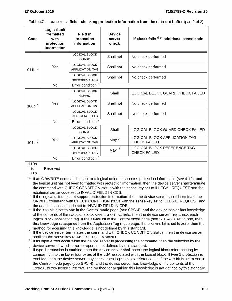
27 October 2010 T10/1799-D Revision 25
Working Draft SCSI Block Commands – 3 (SBC-3) 109
011b bYes
LOGICAL BLOCK GUARD
Shall not No check performed
LOGICAL BLOCK APPLICATION TAG
Shall not No check performed
LOGICAL BLOCK REFERENCE TAG
Shall not No check performed
No Error condition a
100b bYes
LOGICAL BLOCK GUARD
Shall LOGICAL BLOCK GUARD CHECK FAILED
LOGICAL BLOCK APPLICATION TAG
Shall not No check performed
LOGICAL BLOCK REFERENCE TAG
Shall not No check performed
No Error condition a
101b bYes
LOGICAL BLOCK GUARD
Shall LOGICAL BLOCK GUARD CHECK FAILED
LOGICAL BLOCK APPLICATION TAG
May c LOGICAL BLOCK APPLICATION TAG CHECK FAILED
LOGICAL BLOCK REFERENCE TAG
May f LOGICAL BLOCK REFERENCE TAG CHECK FAILED
No Error condition a
110b to
111bReserved
Table 47 — ORPROTECT field - checking protection information from the data-out buffer (part 2 of 2)
Code
Logical unit formatted
with protection
information
Field in protection
information
Device server check
If check fails d e, additional sense code
a If an ORWRITE command is sent to a logical unit that supports protection information (see 4.19), and the logical unit has not been formatted with protection information, then the device server shall terminate the command with CHECK CONDITION status with the sense key set to ILLEGAL REQUEST and the additional sense code set to INVALID FIELD IN CDB.
b If the logical unit does not support protection information, then the device server should terminate the ORWITE command with CHECK CONDITION status with the sense key set to ILLEGAL REQUEST and the additional sense code set to INVALID FIELD IN CDB.
c If the ATO bit is set to one in the Control mode page (see SPC-4), and the device server has knowledge of the contents of the LOGICAL BLOCK APPLICATION TAG field, then the device server may check each logical block application tag. If the ATMPE bit in the Control mode page (see SPC-4) is set to one, then this knowledge is acquired from the Application Tag mode page. If the ATMPE bit is set to zero, then the method for acquiring this knowledge is not defined by this standard.
d If the device server terminates the command with CHECK CONDITION status, then the device server shall set the sense key to ABORTED COMMAND.
e If multiple errors occur while the device server is processing the command, then the selection by the device server of which error to report is not defined by this standard.
f If type 1 protection is enabled, then the device server shall check the logical block reference tag by comparing it to the lower four bytes of the LBA associated with the logical block. If type 3 protection is enabled, then the device server may check each logical block reference tag if the ATO bit is set to one in the Control mode page (see SPC-4), and the device server has knowledge of the contents of the LOGICAL BLOCK REFERENCE TAG. The method for acquiring this knowledge is not defined by this standard.

T10/1799-D Revision 25 27 October 2010
110 Working Draft SCSI Block Commands – 3 (SBC-3)
5.6 ORWRITE (32) commandThe ORWRITE (32) command (see table 48) requests that the device server perform one of the following operations:
a) a change generation and clear operation (see 4.26.3); orb) a set operation (see 4.26.4).
Each logical block includes user data and may include protection information, based on the ORPROTECT field and the medium format.
The OPERATION CODE field, the ADDITIONAL CDB LENGTH field, and the SERVICE ACTION field are defined in SPC-4 and shall be set to the value defined in table 45.
The contents of the CONTROL byte are defined in SAM-4.
Table 48 — ORWRITE (32) command
BitByte 7 6 5 4 3 2 1 0
0 OPERATION CODE (7Fh)
1 CONTROL
2 Reserved BMOP
3 Reserved PREVIOUS GENERATION PROCESSING
4Reserved
5
6 Reserved GROUP NUMBER
7 ADDITIONAL CDB LENGTH (18h)
8 (MSB)SERVICE ACTION (000Eh)
9 (LSB)
10 ORPROTECT DPO FUA Reserved FUA_NV Reserved
11 Reserved
12 (MSB)
LOGICAL BLOCK ADDRESS.....19 (LSB)
20 (MSB)
EXPECTED ORWGENERATION.....23 (LSB)
24 (MSB)
NEW ORWGENERATION.....27 (LSB)
28 (MSB)
TRANSFER LENGTH.....31 (LSB)

27 October 2010 T10/1799-D Revision 25
Working Draft SCSI Block Commands – 3 (SBC-3) 111
The bitmap operation (BMOP) field specifies the operation as described in table 49.
The PREVIOUS GENERATION PROCESSING field specifies the policy for processing future set operations that is to be established in the device server by a successful change generation and clear operation (see 4.26.2.2).
See the WRITE (10) command (see 5.32) for the definitions of the FUA bit and the FUA_NV bit. See the READ (10) command (see 5.11) for the definition of the DPO bit. See the PRE-FETCH (10) command (see 5.7) for the definition of the LOGICAL BLOCK ADDRESS field. See the PRE-FETCH (10) command (see 5.7) and 4.20 for the definition of the GROUP NUMBER field.
The EXPECTED OWRGENERATION field contains a code that is compared with generation codes established and maintained by the device server.
The NEW OWRGENERATION field specifies the current ORWgeneration code that is to be established in the device server by a successful change generation and clear operation (see 4.26.3).
The TRANSFER LENGTH field specifies the number of contiguous logical blocks of data that are read, transferred from the data-out buffer, and processed by the device server using a bitmap buffer (see 3.1.7), starting with the logical block specified by the LOGICAL BLOCK ADDRESS field. If the logical block address plus the transfer length exceeds the capacity of the medium, then the device server shall terminate the command with CHECK CONDITION status with the sense key set to ILLEGAL REQUEST and the additional sense code set to LOGICAL BLOCK ADDRESS OUT OF RANGE. The TRANSFER LENGTH field is constrained by the MAXIMUM TRANSFER LENGTH field in the Block Limits VPD page (see 6.5.3).
The device server shall:
a) check protection information read from the medium based on the ORPROTECT field as described in table 46; and
b) check protection information transferred from the data-out buffer based on the ORPROTECT field as described in table 47.
The order of the user data and protection information checks and comparisons is vendor specific.
Table 49 — BMOP field
Code Description
000bThe device server shall process a set operation (see 4.26.4), and the contents of the PREVIOUS GENERATION PROCESSING field and NEW ORWGENERATION field shall be ignored.
001b The device server shall process a change generation and clear operation (see 4.26.3).
All others Reserved

T10/1799-D Revision 25 27 October 2010
112 Working Draft SCSI Block Commands – 3 (SBC-3)
5.7 PRE-FETCH (10) commandThe PRE-FETCH (10) command (see table 50) requests that the device server:
a) transfer the logical blocks for any mapped LBAs specified by the command from the medium to the volatile cache and/or non-volatile cache; and
b) for any unmapped LBAs specified by the command, update the volatile cache and/or non-volatile cache to prevent retrieval of stale data.
Logical blocks include user data and, if the medium is formatted with protection information enabled, protection information. No data shall be transferred to the data-in buffer.
The OPERATION CODE field is defined in SPC-4 and is set to the value defined in table 50.
An immediate (IMMED) bit set to zero specifies that status shall be returned after the operation is complete. An IMMED bit set to one specifies that status shall be returned as soon as the CDB has been validated.
The LOGICAL BLOCK ADDRESS field specifies the LBA of the first logical block (see 4.5) accessed by this command. If the specified LBA exceeds the capacity of the medium, then the device server shall terminate the command with CHECK CONDITION status with the sense key set to ILLEGAL REQUEST and the additional sense code set to LOGICAL BLOCK ADDRESS OUT OF RANGE.
The GROUP NUMBER field specifies the group into which attributes associated with the command should be collected (see 4.20). A GROUP NUMBER field set to zero specifies that any attributes associated with the command shall not be collected into any group.
The PREFETCH LENGTH field specifies the number of contiguous logical blocks that shall be pre-fetched (i.e., transferred to the cache from the medium), starting with the logical block specified by the LOGICAL BLOCK ADDRESS field. A PREFETCH LENGTH field set to zero specifies that all logical blocks starting with the one specified in the LOGICAL BLOCK ADDRESS field to the last logical block on the medium shall be pre-fetched. Any other value specifies the number of logical blocks that shall be pre-fetched. If the LBA plus the prefetch length exceeds the capacity of the medium, then the device server shall terminate the command with CHECK CONDITION status with the sense key set to ILLEGAL REQUEST and the additional sense code set to LOGICAL BLOCK ADDRESS OUT OF RANGE. The device server is not required to transfer logical blocks that already are contained in the cache.
The contents of the CONTROL byte are defined in SAM-4.
If the IMMED bit is set to zero and the specified logical blocks were successfully transferred to the cache, then the device server shall complete the command with CONDITION MET status.
If the IMMED bit is set to zero and the cache does not have sufficient capacity to accept all of the specified logical blocks, then the device server shall transfer to the cache as many of the specified logical blocks that fit.
Table 50 — PRE-FETCH (10) command
BitByte 7 6 5 4 3 2 1 0
0 OPERATION CODE (34h)
1 Reserved IMMED Obsolete
2 (MSB)
LOGICAL BLOCK ADDRESS.....5 (LSB)
6 Reserved GROUP NUMBER
7 (MSB)PREFETCH LENGTH
8 (LSB)
9 CONTROL

27 October 2010 T10/1799-D Revision 25
Working Draft SCSI Block Commands – 3 (SBC-3) 113
If these logical blocks are transferred successfully, then the device server shall complete the command with GOOD status.
If the IMMED bit is set to one and the cache has sufficient capacity to accept all of the specified logical blocks, then the device server shall complete the command with CONDITION MET status.
If the IMMED bit is set to one and the cache does not have sufficient capacity to accept all of the specified logical blocks, then the device server shall complete the command with GOOD status.
If the IMMED bit is set to zero and one or more of the specified logical blocks were not successfully transferred to the cache for reasons other than lack of cache capacity, then the device server shall terminate the command with CHECK CONDITION status with the sense key and the additional sense code set to the appropriate values. If the IMMED bit is set to one and one or more of the specified logical blocks were not successfully transferred to the cache for reasons other than lack of cache capacity, the device server shall report a deferred error (see SPC-4).
5.8 PRE-FETCH (16) commandThe PRE-FETCH (16) command (see table 51) requests that the device server:
a) transfer the logical blocks for any mapped LBAs specified by the command from the medium to the volatile cache and/or non-volatile cache; and
b) for any unmapped LBAs specified by the command, update the volatile cache and/or non-volatile cache to prevent retrieval of stale data.
Logical blocks include user data and, if the medium is formatted with protection information enabled, protection information. No data shall be transferred to the data-in buffer.
The OPERATION CODE field is defined in SPC-4 and is set to the value defined in table 51.
See the PRE-FETCH (10) command (see 5.7) for the definitions of the other fields in this command.
Table 51 — PRE-FETCH (16) command
BitByte 7 6 5 4 3 2 1 0
0 OPERATION CODE (90h)
1 Reserved IMMED Reserved
2 (MSB)
LOGICAL BLOCK ADDRESS.....9 (LSB)
10 (MSB)
PREFETCH LENGTH.....13 (LSB)
14 Reserved GROUP NUMBER
15 CONTROL

T10/1799-D Revision 25 27 October 2010
114 Working Draft SCSI Block Commands – 3 (SBC-3)
5.9 PREVENT ALLOW MEDIUM REMOVAL commandThe PREVENT ALLOW MEDIUM REMOVAL command (see table 52) requests that the logical unit enable or disable the removal of the medium. If medium removal is prevented on any I_T nexus that has access to the logical unit, then the logical unit shall not allow medium removal.
The OPERATION CODE field is defined in SPC-4 and is set to the value defined in table 52.
Table 53 defines the PREVENT field values and their meanings.
The contents of the CONTROL byte are defined in SAM-4.
The prevention of medium removal shall begin when any application client issues a PREVENT ALLOW MEDIUM REMOVAL command with the PREVENT field set to 01b (i.e., medium removal prevented). The prevention of medium removal for the logical unit shall terminate after:
a) one of the following occurs for each I_T nexus through which medium removal had been prevented:A) receipt of a PREVENT ALLOW MEDIUM REMOVAL command with the PREVENT field set to 00b;
orB) an I_T nexus loss;
b) a power on;c) a hard reset; ord) a logical unit reset.
If possible, the device server shall perform a synchronize cache operation before terminating the prevention of medium removal.
If a persistent reservation or registration is being preempted by a PERSISTENT RESERVE OUT command with PREEMPT AND ABORT service action (see SPC-4), then the equivalent of a PREVENT ALLOW MEDIUM REMOVAL command with the PREVENT field set to zero shall be processed for each the I_T nexuses associated with the persistent reservation or registrations being preempted. This allows an application client to override the prevention of medium removal function for an initiator port that is no longer operating correctly.
While a prevention of medium removal condition is in effect, the logical unit shall inhibit mechanisms that allow removal of the medium by an operator.
Table 52 — PREVENT ALLOW MEDIUM REMOVAL command
BitByte 7 6 5 4 3 2 1 0
0 OPERATION CODE (1Eh)
1 Reserved
2 Reserved
3 Reserved
4 Reserved PREVENT
5 CONTROL
Table 53 — PREVENT field
Value Description00b Medium removal shall be allowed.01b Medium removal shall be prohibited.
10b to 11b Obsolete

27 October 2010 T10/1799-D Revision 25
Working Draft SCSI Block Commands – 3 (SBC-3) 115
5.10 READ (6) commandThe READ (6) command (see table 54) requests that the device server read the specified logical block(s) and transfer them to the data-in buffer. Each logical block read includes user data and, if the medium is formatted with protection information enabled, protection information. Each logical block transferred includes user data but does not include protection information.
The OPERATION CODE field is defined in SPC-4 and is set to the value defined in table 54.
The cache control bits (see 5.11) are not provided for this command. Direct-access block devices with cache may have values for the cache control bits that affect the READ (6) command; however, no default values are defined by this standard. If explicit control is required, then the READ (10) command should be used.
See the PRE-FETCH (10) command (see 5.7) for the definition of the LOGICAL BLOCK ADDRESS field.
The TRANSFER LENGTH field specifies the number of contiguous logical blocks of data that shall be read and transferred to the data-in buffer, starting with the logical block specified by the LOGICAL BLOCK ADDRESS field. A TRANSFER LENGTH field set to zero specifies that 256 logical blocks shall be read. Any other value specifies the number of logical blocks that shall be read. If the LBA plus the transfer length exceeds the capacity of the medium, then the device server shall terminate the command with CHECK CONDITION status with the sense key set to ILLEGAL REQUEST and the additional sense code set to LOGICAL BLOCK ADDRESS OUT OF RANGE. The TRANSFER LENGTH field is constrained by the MAXIMUM TRANSFER LENGTH field in the Block Limits VPD page (see 6.5.3).
NOTE 9 - For the READ (10) command, READ (12) command, READ (16) command, and READ (32) command, a TRANSFER LENGTH field set to zero specifies that no logical blocks are read.
NOTE 10 - Although the READ (6) command is limited to addressing up to 2 097 151 logical blocks, this command has been maintained as mandatory since some system initialization routines require that the READ (6) command be used. System initialization routines should migrate from the READ (6) command to the READ (10) command, which is capable of addressing 4 294 947 295 logical blocks, or the READ (16) command, which is capable of addressing 18 446 744 073 709 551 615 logical blocks.
The contents of the CONTROL byte are defined in SAM-4.
Table 54 — READ (6) command
BitByte 7 6 5 4 3 2 1 0
0 OPERATION CODE (08h)
1 Reserved (MSB)
2LOGICAL BLOCK ADDRESS
3 (LSB)
4 TRANSFER LENGTH
5 CONTROL

T10/1799-D Revision 25 27 October 2010
116 Working Draft SCSI Block Commands – 3 (SBC-3)
The device server shall check the protection information read from the medium before returning status for the command as described in table 55.
Table 55 — Protection information checking for READ (6)
Logical unit formatted
with protection
information
Shall device server
transmit protection
information?
Field in protection
information e
Extended INQUIRY Data VPD page bit
value d
If check fails b c, additional sense code
Yes gNo
LOGICAL BLOCK GUARD
GRD_CHK = 1 LOGICAL BLOCK GUARD CHECK FAILED
GRD_CHK = 0 No check performed
LOGICAL BLOCK APPLICATION TAG
APP_CHK = 1 aLOGICAL BLOCK APPLICATION TAG CHECK FAILED
APP_CHK = 0 No check performed
LOGICAL BLOCK REFERENCE TAG
REF_CHK = 1 fLOGICAL BLOCK REFERENCE TAG CHECK FAILED
REF_CHK = 0 No check performed
No No protection information available to checka If the device server has knowledge of the contents of the LOGICAL BLOCK APPLICATION TAG field, then the
device server shall check each logical block application tag. If the ATMPE bit in the Control mode page (see SPC-4) is set to one, then this knowledge is acquired from the Application Tag mode page. If the ATMPE bit is set to zero, then the method for acquiring this knowledge is not defined by this standard.
b If the device server terminates the command with CHECK CONDITION status, then the device server shall set the sense key to ABORTED COMMAND.
c If multiple errors occur while the device server is processing the command, then the selection by the device server of which error to report is not defined by this standard.
d See the Extended INQUIRY Data VPD page (see SPC-4) for the definitions of the GRD_CHK bit, the APP_CHK bit, and the REF_CHK bit.
e If the device server detects:a) a LOGICAL BLOCK APPLICATION TAG field set to FFFFh, and type 1 protection (see 4.19.2.3) or type 2
protection (see 4.19.2.4) is enabled; orb) a LOGICAL BLOCK APPLICATION TAG field set to FFFFh, the LOGICAL BLOCK REFERENCE TAG field set to
FFFF_FFFFh, and type 3 protection (see 4.19.2.5) is enabled,then the device server shall not check any protection information in the associated logical block.
f If type 1 protection is enabled, then the device server shall check the logical block reference tag by comparing it to the lower four bytes of the LBA associated protection information interval. If type 2 protection or type 3 protection is enabled, then the device server shall check each logical block reference tag only if the device server has knowledge of the contents of the LOGICAL BLOCK REFERENCE TAG field. The method for acquiring this knowledge is not defined by this standard.
g If the DPICZ bit in the Control mode page (see SPC-4) is set to one, then protection information shall not be checked.
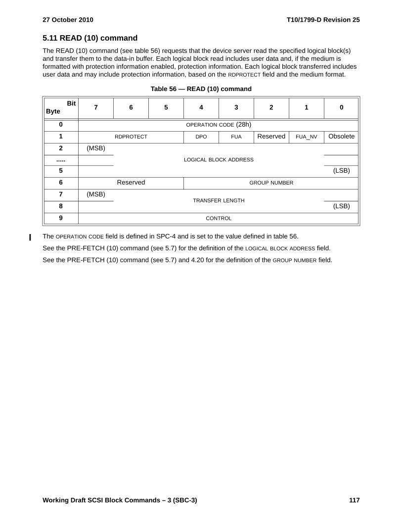
27 October 2010 T10/1799-D Revision 25
Working Draft SCSI Block Commands – 3 (SBC-3) 117
5.11 READ (10) commandThe READ (10) command (see table 56) requests that the device server read the specified logical block(s) and transfer them to the data-in buffer. Each logical block read includes user data and, if the medium is formatted with protection information enabled, protection information. Each logical block transferred includes user data and may include protection information, based on the RDPROTECT field and the medium format.
The OPERATION CODE field is defined in SPC-4 and is set to the value defined in table 56.
See the PRE-FETCH (10) command (see 5.7) for the definition of the LOGICAL BLOCK ADDRESS field.
See the PRE-FETCH (10) command (see 5.7) and 4.20 for the definition of the GROUP NUMBER field.
Table 56 — READ (10) command
BitByte 7 6 5 4 3 2 1 0
0 OPERATION CODE (28h)
1 RDPROTECT DPO FUA Reserved FUA_NV Obsolete
2 (MSB)
LOGICAL BLOCK ADDRESS.....5 (LSB)
6 Reserved GROUP NUMBER
7 (MSB)TRANSFER LENGTH
8 (LSB)
9 CONTROL
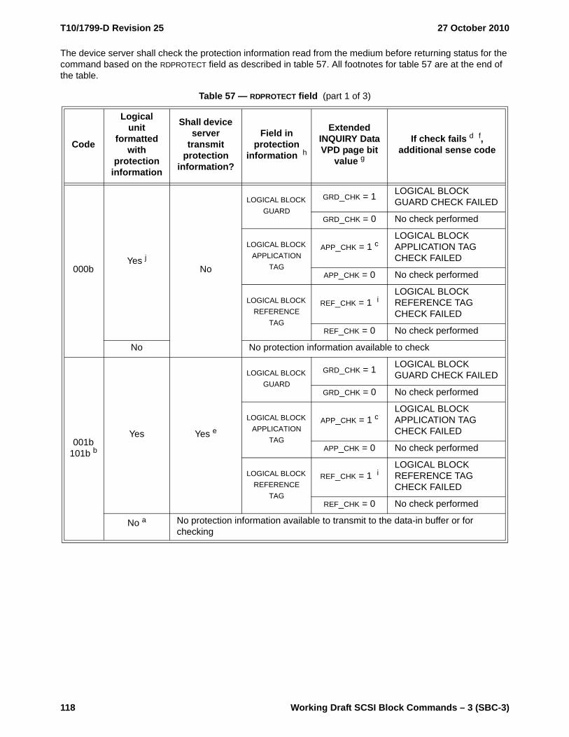
T10/1799-D Revision 25 27 October 2010
118 Working Draft SCSI Block Commands – 3 (SBC-3)
The device server shall check the protection information read from the medium before returning status for the command based on the RDPROTECT field as described in table 57. All footnotes for table 57 are at the end of the table.
Table 57 — RDPROTECT field (part 1 of 3)
Code
Logical unit
formatted with
protection information
Shall device server
transmit protection
information?
Field in protection
information h
Extended INQUIRY Data VPD page bit
value g
If check fails d f, additional sense code
000bYes j
No
LOGICAL BLOCK GUARD
GRD_CHK = 1 LOGICAL BLOCK GUARD CHECK FAILED
GRD_CHK = 0 No check performed
LOGICAL BLOCK APPLICATION
TAG
APP_CHK = 1 cLOGICAL BLOCK APPLICATION TAG CHECK FAILED
APP_CHK = 0 No check performed
LOGICAL BLOCK REFERENCE
TAG
REF_CHK = 1 iLOGICAL BLOCK REFERENCE TAG CHECK FAILED
REF_CHK = 0 No check performed
No No protection information available to check
001b101b b
Yes Yes e
LOGICAL BLOCK GUARD
GRD_CHK = 1 LOGICAL BLOCK GUARD CHECK FAILED
GRD_CHK = 0 No check performed
LOGICAL BLOCK APPLICATION
TAG
APP_CHK = 1 cLOGICAL BLOCK APPLICATION TAG CHECK FAILED
APP_CHK = 0 No check performed
LOGICAL BLOCK REFERENCE
TAG
REF_CHK = 1 iLOGICAL BLOCK REFERENCE TAG CHECK FAILED
REF_CHK = 0 No check performed
No a No protection information available to transmit to the data-in buffer or for checking

27 October 2010 T10/1799-D Revision 25
Working Draft SCSI Block Commands – 3 (SBC-3) 119
010b bYes Yes e
LOGICAL BLOCK GUARD
No check performed
LOGICAL BLOCK APPLICATION
TAG
APP_CHK = 1 cLOGICAL BLOCK APPLICATION TAG CHECK FAILED
APP_CHK = 0 No check performed
LOGICAL BLOCK REFERENCE
TAG
REF_CHK = 1 iLOGICAL BLOCK REFERENCE TAG CHECK FAILED
REF_CHK = 0 No check performed
No a No protection information available to transmit to the data-in buffer or for checking
011b bYes Yes e
LOGICAL BLOCK GUARD
No check performed
LOGICAL BLOCK APPLICATION
TAGNo check performed
LOGICAL BLOCK REFERENCE
TAGNo check performed
No a No protection information available to transmit to the data-in buffer or for checking
100b bYes Yes e
LOGICAL BLOCK GUARD
GRD_CHK = 1 LOGICAL BLOCK GUARD CHECK FAILED
GRD_CHK = 0 No check performed
LOGICAL BLOCK APPLICATION
TAGNo check performed
LOGICAL BLOCK REFERENCE
TAGNo check performed
No a No protection information available to transmit to the data-in buffer or for checking
110b to 111b Reserved
Table 57 — RDPROTECT field (part 2 of 3)
Code
Logical unit
formatted with
protection information
Shall device server
transmit protection
information?
Field in protection
information h
Extended INQUIRY Data VPD page bit
value g
If check fails d f, additional sense code

T10/1799-D Revision 25 27 October 2010
120 Working Draft SCSI Block Commands – 3 (SBC-3)
A disable page out (DPO) bit set to zero specifies that the retention priority shall be determined by the RETENTION PRIORITY fields in the Caching mode page (see 6.4.5). A DPO bit set to one specifies that the device server shall assign the logical blocks accessed by this command the lowest retention priority for being fetched into or retained by the cache. A DPO bit set to one overrides any retention priority specified in the Caching mode page. All other aspects of the algorithm implementing the cache replacement strategy are not defined by this standard.
NOTE 11 - The DPO bit is used to control replacement of logical blocks in the cache when the application client has information on the future usage of the logical blocks. If the DPO bit is set to one, then the application
a If a logical unit supports protection information (see 4.19) but has not been formatted with protection information, then the device server shall terminate a command specifying a verify operation to the logical unit with CHECK CONDITION status with the sense key set to ILLEGAL REQUEST and the additional sense code set to INVALID FIELD IN CDB.
b If the logical unit does not support protection information, then the device server should terminate the command with CHECK CONDITION status with the sense key set to ILLEGAL REQUEST and the additional sense code set to INVALID FIELD IN CDB.
c If the device server has knowledge of the contents of the LOGICAL BLOCK APPLICATION TAG field, then the device server shall check each logical block application tag. If the ATO bit in the Control mode page (see SPC-4) is set to one, then this knowledge is acquired from:a) the EXPECTED LOGICAL BLOCK APPLICATION TAG field and the LOGICAL BLOCK APPLICATION TAG MASK
field in the CDB, if a READ (32) command (see 5.14) is received by the device server;b) the Application Tag mode page (see 6.4.3), if a command other than READ (32) is received by the
device server, and the ATMPE bit in the Control mode page (see SPC-4) is set to one; orc) a method not defined by this standard, if a command other than READ (32) is received by the
device server, and the ATMPE bit is set to zero.d If the device server terminates the command with CHECK CONDITION status, then the device server
shall set the sense key to ABORTED COMMAND.e The device server shall transmit protection information to the data-in buffer.f If multiple errors occur while the device server is processing the command, then the selection by the
device server of which error to report is not defined by this standard.g See the Extended INQUIRY Data VPD page (see SPC-4) for the definitions of the GRD_CHK bit, the
APP_CHK bit, and the REF_CHK bit.h If the device server detects:
a) a LOGICAL BLOCK APPLICATION TAG field set to FFFFh, and type 1 protection (see 4.19.2.3) or type 2 protection (see 4.19.2.4) is enabled; or
b) a LOGICAL BLOCK APPLICATION TAG field set to FFFFh, the LOGICAL BLOCK REFERENCE TAG field set to FFFF_FFFFh, and type 3 protection (see 4.19.2.5) is enabled,
then the device server shall not check any protection information in the associated protection information interval.
i If type 1 protection is enabled, then the device server shall check the logical block reference tag by comparing it to the lower four bytes of the LBA associated with the logical block. If type 2 protection or type 3 protection is enabled, and the device server has knowledge of the contents of the LOGICAL BLOCK REFERENCE TAG field, then the device server shall check each logical block reference tag. If type 2 protection is enabled, then this knowledge may be acquired through the EXPECTED INITIAL LOGICAL BLOCK REFERENCE TAG field in a READ (32) command (see 5.14). If type 3 protection is enabled, then the method for acquiring this knowledge is not defined by this standard.
j If the DPICZ bit in the Control mode page (see SPC-4) is set to one, then protection information shall not be checked.
Table 57 — RDPROTECT field (part 3 of 3)
Code
Logical unit
formatted with
protection information
Shall device server
transmit protection
information?
Field in protection
information h
Extended INQUIRY Data VPD page bit
value g
If check fails d f, additional sense code

27 October 2010 T10/1799-D Revision 25
Working Draft SCSI Block Commands – 3 (SBC-3) 121
client is specifying that the logical blocks accessed by the command are not likely to be accessed again in the near future and should not be put in the cache nor retained by the cache. If the DPO bit is set to zero, then the application client is specifying that the logical blocks accessed by this command are likely to be accessed again in the near future.
The force unit access (FUA) and force unit access non-volatile cache (FUA_NV) bits are defined in table 58.
The TRANSFER LENGTH field specifies the number of contiguous logical blocks of data that shall be read and transferred to the data-in buffer, starting with the logical block specified by the LOGICAL BLOCK ADDRESS field. A TRANSFER LENGTH field set to zero specifies that no logical blocks shall be read. This condition shall not be considered an error. Any other value specifies the number of logical blocks that shall be read. If the LBA plus the transfer length exceeds the capacity of the medium, then the device server shall terminate the command with CHECK CONDITION status with the sense key set to ILLEGAL REQUEST and the additional sense code set to LOGICAL BLOCK ADDRESS OUT OF RANGE. The TRANSFER LENGTH field is constrained by the MAXIMUM TRANSFER LENGTH field in the Block Limits VPD page (see 6.5.3).
NOTE 12 - For the READ (6) command, a TRANSFER LENGTH field set to zero specifies that 256 logical blocks are read.
The contents of the CONTROL byte are defined in SAM-4.
Table 58 — Force unit access for read operations
FUA FUA_NV Description
0 0 The device server may read the logical blocks from volatile cache, non-volatile cache, and/or the medium.
0 1
If the NV_SUP bit is set to one in the Extended INQUIRY Data VPD page (see SPC-4), then the device server shall read the logical blocks from non-volatile cache or the medium. If a non-volatile cache is present and a volatile cache contains a more recent version of a logical block, then the device server shall write the logical block to:
a) non-volatile cache; and/orb) the medium,
before reading it.
If the NV_SUP bit is set to zero in the Extended INQUIRY Data VPD page (see SPC-4), then the device server may read the logical blocks from volatile cache, non-volatile cache, and/or the medium.
1 0 or 1The device server shall read the logical blocks from the medium. If a cache contains a more recent version of a logical block, then the device server shall write the logical block to the medium before reading it.
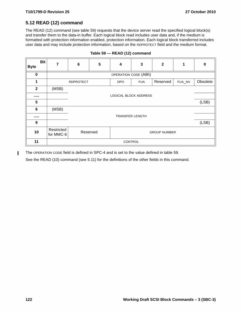
T10/1799-D Revision 25 27 October 2010
122 Working Draft SCSI Block Commands – 3 (SBC-3)
5.12 READ (12) commandThe READ (12) command (see table 59) requests that the device server read the specified logical block(s) and transfer them to the data-in buffer. Each logical block read includes user data and, if the medium is formatted with protection information enabled, protection information. Each logical block transferred includes user data and may include protection information, based on the RDPROTECT field and the medium format.
The OPERATION CODE field is defined in SPC-4 and is set to the value defined in table 59.
See the READ (10) command (see 5.11) for the definitions of the other fields in this command.
Table 59 — READ (12) command
BitByte 7 6 5 4 3 2 1 0
0 OPERATION CODE (A8h)
1 RDPROTECT DPO FUA Reserved FUA_NV Obsolete
2 (MSB)
LOGICAL BLOCK ADDRESS.....5 (LSB)
6 (MSB)
TRANSFER LENGTH.....9 (LSB)
10 Restricted for MMC-6 Reserved GROUP NUMBER
11 CONTROL

27 October 2010 T10/1799-D Revision 25
Working Draft SCSI Block Commands – 3 (SBC-3) 123
5.13 READ (16) commandThe READ (16) command (see table 60) requests that the device server read the specified logical block(s) and transfer them to the data-in buffer. Each logical block read includes user data and, if the medium is formatted with protection information enabled, protection information. Each logical block transferred includes user data and may include protection information, based on the RDPROTECT field and the medium format.
The OPERATION CODE field is defined in SPC-4 and is set to the value defined in table 60.
See the READ (10) command (see 5.11) for the definitions of the other fields in this command.
Table 60 — READ (16) command
BitByte 7 6 5 4 3 2 1 0
0 OPERATION CODE (88h)
1 RDPROTECT DPO FUA Reserved FUA_NV Reserved
2 (MSB)
LOGICAL BLOCK ADDRESS.....9 (LSB)
10 (MSB)
TRANSFER LENGTH.....13 (LSB)
14 Restricted for MMC-6 Reserved GROUP NUMBER
15 CONTROL

T10/1799-D Revision 25 27 October 2010
124 Working Draft SCSI Block Commands – 3 (SBC-3)
5.14 READ (32) commandThe READ (32) command (see table 61) requests that the device server read the specified logical block(s) and transfer them to the data-in buffer. Each logical block read includes user data and, if the medium is formatted with protection information enabled, protection information. Each logical block transferred includes user data and may include protection information, based on the RDPROTECT field and the medium format.
The READ (32) command shall only be processed if type 2 protection is enabled (see 4.19.2.4).
The OPERATION CODE field, ADDITIONAL CDB LENGTH field, and SERVICE ACTION field are defined in SPC-4 and shall be set to the values defined in table 61.
See the READ (10) command (see 5.11) for the definitions of the CONTROL byte, GROUP NUMBER field, the RDPROTECT field, the DPO bit, the FUA bit, the FUA_NV bit, the LOGICAL BLOCK ADDRESS field, and the TRANSFER LENGTH field.
When checking of the LOGICAL BLOCK REFERENCE TAG field is enabled (see table 57 in 5.11), the EXPECTED INITIAL LOGICAL BLOCK REFERENCE TAG field contains the value of the LOGICAL BLOCK REFERENCE TAG field
Table 61 — READ (32) command
BitByte 7 6 5 4 3 2 1 0
0 OPERATION CODE (7Fh)
1 CONTROL
2Reserved.....
5
6 Reserved GROUP NUMBER
7 ADDITIONAL CDB LENGTH (18h)
8 (MSB)SERVICE ACTION (0009h)
9 (LSB)
10 RDPROTECT DPO FUA Reserved FUA_NV Reserved
11 Reserved
12 (MSB)
LOGICAL BLOCK ADDRESS.....19 (LSB)
20 (MSB)
EXPECTED INITIAL LOGICAL BLOCK REFERENCE TAG.....23 (LSB)
24 (MSB)EXPECTED LOGICAL BLOCK APPLICATION TAG
25 (LSB)
26 (MSB)LOGICAL BLOCK APPLICATION TAG MASK
27 (LSB)
28 (MSB)
TRANSFER LENGTH.....31 (LSB)

27 October 2010 T10/1799-D Revision 25
Working Draft SCSI Block Commands – 3 (SBC-3) 125
expected in the protection information of the first logical block accessed by the command instead of a value based on the LBA (see 4.19.3).
If the ATO bit is set to one in the Control mode page (see SPC-4), and checking of the LOGICAL BLOCK APPLICATION TAG field is enabled (see table 57 in 5.11), then the LOGICAL BLOCK APPLICATION TAG MASK field contains a value that is a bit mask for enabling the checking of the LOGICAL BLOCK APPLICATION TAG field in every instance of protection information for each logical block accessed by the command. A LOGICAL BLOCK APPLICATION TAG MASK field bit set to one enables the checking of the corresponding bit of the EXPECTED LOGICAL BLOCK APPLICATION TAG field with the corresponding bit of the LOGICAL BLOCK APPLICATION TAG field in every instance of protection information.
The LOGICAL BLOCK APPLICATION TAG MASK field and the EXPECTED LOGICAL BLOCK APPLICATION TAG field shall be ignored if:
a) the ATO bit is set to zero; orb) the ATO bit is set to one in the Control mode page (see SPC-4), and checking of the LOGICAL BLOCK
APPLICATION TAG field is disabled (see table 57 in 5.11).
5.15 READ CAPACITY (10) command
5.15.1 READ CAPACITY (10) overview
The READ CAPACITY (10) command (see table 62) requests that the device server transfer 8 bytes of parameter data describing the capacity and medium format of the direct-access block device to the data-in buffer. This command may be processed as if it has a HEAD OF QUEUE task attribute (see 4.14). If the logical unit supports protection information (see 4.19), then the application client should use the READ CAPACITY (16) command instead of the READ CAPACITY (10) command.
The OPERATION CODE field is defined in SPC-4 and is set to the value defined in table 62.
See the PRE-FETCH (10) command (see 5.7) for the definition of the LOGICAL BLOCK ADDRESS field.
The LOGICAL BLOCK ADDRESS field shall be set to zero if the PMI bit is set to zero. If the PMI bit is set to zero and the LOGICAL BLOCK ADDRESS field is not set to zero, then the device server shall terminate the command with CHECK CONDITION status with the sense key set to ILLEGAL REQUEST and the additional sense code set to INVALID FIELD IN CDB.
A partial medium indicator (PMI) bit set to zero specifies that the device server return information on the last logical block on the direct-access block device.
A PMI bit set to one specifies that the device server return information on the last logical block after that specified in the LOGICAL BLOCK ADDRESS field before a substantial vendor specific delay in data transfer may be encountered.
Table 62 — READ CAPACITY (10) command
BitByte 7 6 5 4 3 2 1 0
0 OPERATION CODE (25h)
1 Reserved Obsolete
2 (MSB)LOGICAL BLOCK ADDRESS
5 (LSB)
6Reserved
7
8 Reserved PMI
9 CONTROL

T10/1799-D Revision 25 27 October 2010
126 Working Draft SCSI Block Commands – 3 (SBC-3)
NOTE 13 - This function is intended to assist storage management software in determining whether there is sufficient space starting with the LBA specified in the CDB to contain a frequently accessed data structure (e.g., a file directory or file index) without incurring an extra delay.
The contents of the CONTROL byte are defined in SAM-4.
5.15.2 READ CAPACITY (10) parameter data
The READ CAPACITY (10) parameter data is defined in table 63. Any time the READ CAPACITY (10) parameter data changes, the device server should establish a unit attention condition as described in 4.9.
If the number of logical blocks exceeds the maximum value that is able to be specified in the RETURNED LOGICAL BLOCK ADDRESS field, then the device server shall set the RETURNED LOGICAL BLOCK ADDRESS field to FFFF_FFFFh. The application client should then issue a READ CAPACITY (16) command (see 5.16) to request that the device server transfer the READ CAPACITY (16) parameter data to the data-in buffer.
If the PMI bit is set to zero, then the device server shall set the RETURNED LOGICAL BLOCK ADDRESS field to the lower of:
a) the LBA of the last logical block on the direct-access block device; orb) FFFF_FFFFh.
If the PMI bit is set to one, then the device server shall set the RETURNED LOGICAL BLOCK ADDRESS field to the lower of:
a) the last LBA after that specified in the LOGICAL BLOCK ADDRESS field of the CDB before a substantial vendor specific delay in data transfer may be encountered; or
b) FFFF_FFFFh.
The RETURNED LOGICAL BLOCK ADDRESS shall be greater than or equal to that specified by the LOGICAL BLOCK ADDRESS field in the CDB.
The LOGICAL BLOCK LENGTH IN BYTES field contains the number of bytes of user data in the logical block indicated by the RETURNED LOGICAL BLOCK ADDRESS field. This value does not include protection information or additional information (e.g., ECC bytes) recorded on the medium.
Table 63 — READ CAPACITY (10) parameter data
BitByte 7 6 5 4 3 2 1 0
0 (MSB)
RETURNED LOGICAL BLOCK ADDRESS.....3 (LSB)
4 (MSB)
LOGICAL BLOCK LENGTH IN BYTES.....7 (LSB)

27 October 2010 T10/1799-D Revision 25
Working Draft SCSI Block Commands – 3 (SBC-3) 127
5.16 READ CAPACITY (16) command
5.16.1 READ CAPACITY (16) command overview
The READ CAPACITY (16) command (see table 64) requests that the device server transfer parameter data describing the capacity and medium format of the direct-access block device to the data-in buffer. This command is mandatory if the logical unit supports protection information (see 4.19) and is optional otherwise. This command is implemented as a service action of the SERVICE ACTION IN operation code (see A.2). This command may be processed as if it has a HEAD OF QUEUE task attribute (see 4.14).
The OPERATION CODE field and SERVICE ACTION field are defined in SPC-4 and shall be set to the values defined in table 64.
See the READ CAPACITY (10) command (see 5.15) for definitions of the LOGICAL BLOCK ADDRESS field and the PMI bit.
The ALLOCATION LENGTH field is defined in the GET LBA STATUS command (see 5.4).
The contents of the CONTROL byte are defined in SAM-4.
Table 64 — READ CAPACITY (16) command
BitByte 7 6 5 4 3 2 1 0
0 OPERATION CODE (9Eh)
1 Reserved SERVICE ACTION (10h)
2 (MSB)
LOGICAL BLOCK ADDRESS.....9 (LSB)
10 (MSB)
ALLOCATION LENGTH.....13 (LSB)
14 Reserved PMI
15 CONTROL

T10/1799-D Revision 25 27 October 2010
128 Working Draft SCSI Block Commands – 3 (SBC-3)
5.16.2 READ CAPACITY (16) parameter data
The READ CAPACITY (16) parameter data is defined in table 65. Any time the READ CAPACITY (16) parameter data changes, the device server should establish a unit attention condition as described in 4.9.
The RETURNED LOGICAL BLOCK ADDRESS field and LOGICAL BLOCK LENGTH IN BYTES field of the READ CAPACITY (16) parameter data are the same as the in the READ CAPACITY (10) parameter data (see 5.15). The maximum value that shall be returned in the RETURNED LOGICAL BLOCK ADDRESS field is FFFF_FFFF_FFFF_FFFEh.
The protection type (P_TYPE) field and the protection enable (PROT_EN) bit (see table 66) indicate the logical unit’s current type of protection.
The P_I_EXPONENT field may be used to determine the number of protection information intervals placed within each logical block (see 5.3.2).
The number of protection information intervals is calculated as follows:
number of protection information intervals = 2(p_i exponent)
where:
p_i exponent is the contents of the P_I EXPONENT field
Table 65 — READ CAPACITY (16) parameter data
BitByte 7 6 5 4 3 2 1 0
0 (MSB)
RETURNED LOGICAL BLOCK ADDRESS.....7 (LSB)
8 (MSB)
LOGICAL BLOCK LENGTH IN BYTES.....11 (LSB)
12 Reserved P_TYPE PROT_EN
13 P_I_EXPONENT LOGICAL BLOCKS PER PHYSICAL BLOCK EXPONENT
14 TPE TPRZ (MSB)LOWEST ALIGNED LOGICAL BLOCK ADDRESS
15 (LSB)
16Reserved.....
31
Table 66 — P_TYPE field and PROT_EN bit
PROT_EN P_TYPE Description
0 xxxb The logical unit is formatted to type 0 protection (see 4.19.2.2).
1 000b The logical unit is formatted to type 1 protection (see 4.19.2.3).
1 001b The logical unit is formatted to type 2 protection (see 4.19.2.4).
1 010b The logical unit is formatted to type 3 protection (see 4.19.2.5).
1 011b to 111b Reserved
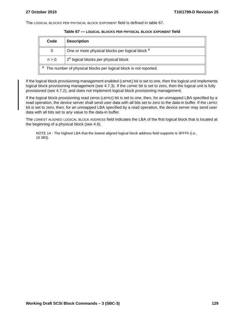
27 October 2010 T10/1799-D Revision 25
Working Draft SCSI Block Commands – 3 (SBC-3) 129
The LOGICAL BLOCKS PER PHYSICAL BLOCK EXPONENT field is defined in table 67.
If the logical block provisioning management enabled (LBPME) bit is set to one, then the logical unit implements logical block provisioning management (see 4.7.3). If the LBPME bit is set to zero, then the logical unit is fully provisioned (see 4.7.2), and does not implement logical block provisioning management.
If the logical block provisioning read zeros (LBPRZ) bit is set to one, then, for an unmapped LBA specified by a read operation, the device server shall send user data with all bits set to zero to the data-in buffer. If the LBPRZ bit is set to zero, then, for an unmapped LBA specified by a read operation, the device server may send user data with all bits set to any value to the data-in buffer.
The LOWEST ALIGNED LOGICAL BLOCK ADDRESS field indicates the LBA of the first logical block that is located at the beginning of a physical block (see 4.6).
NOTE 14 - The highest LBA that the lowest aligned logical block address field supports is 3FFFh (i.e., 16 383).
Table 67 — LOGICAL BLOCKS PER PHYSICAL BLOCK EXPONENT field
Code Description
0 One or more physical blocks per logical block a
n > 0 2n logical blocks per physical block
a The number of physical blocks per logical block is not reported.
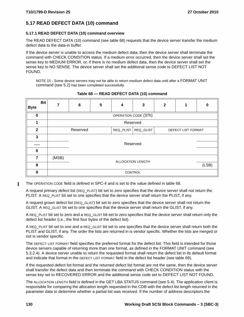
T10/1799-D Revision 25 27 October 2010
130 Working Draft SCSI Block Commands – 3 (SBC-3)
5.17 READ DEFECT DATA (10) command
5.17.1 READ DEFECT DATA (10) command overview
The READ DEFECT DATA (10) command (see table 68) requests that the device server transfer the medium defect data to the data-in buffer.
If the device server is unable to access the medium defect data, then the device server shall terminate the command with CHECK CONDITION status. If a medium error occurred, then the device server shall set the sense key to MEDIUM ERROR, or, if there is no medium defect data, then the device server shall set the sense key to NO SENSE. The device server shall set the additional sense code to DEFECT LIST NOT FOUND.
NOTE 15 - Some device servers may not be able to return medium defect data until after a FORMAT UNIT command (see 5.2) has been completed successfully.
The OPERATION CODE field is defined in SPC-4 and is set to the value defined in table 68.
A request primary defect list (REQ_PLIST) bit set to zero specifies that the device server shall not return the PLIST. A REQ_PLIST bit set to one specifies that the device server shall return the PLIST, if any.
A request grown defect list (REQ_GLIST) bit set to zero specifies that the device server shall not return the GLIST. A REQ_GLIST bit set to one specifies that the device server shall return the GLIST, if any.
A REQ_PLIST bit set to zero and a REQ_GLIST bit set to zero specifies that the device server shall return only the defect list header (i.e., the first four bytes of the defect list).
A REQ_PLIST bit set to one and a REQ_GLIST bit set to one specifies that the device server shall return both the PLIST and GLIST, if any. The order the lists are returned in is vendor specific. Whether the lists are merged or not is vendor specific.
The DEFECT LIST FORMAT field specifies the preferred format for the defect list. This field is intended for those device servers capable of returning more than one format, as defined in the FORMAT UNIT command (see 5.3.2.4). A device server unable to return the requested format shall return the defect list in its default format and indicate that format in the DEFECT LIST FORMAT field in the defect list header (see table 69).
If the requested defect list format and the returned defect list format are not the same, then the device server shall transfer the defect data and then terminate the command with CHECK CONDITION status with the sense key set to RECOVERED ERROR and the additional sense code set to DEFECT LIST NOT FOUND.
The ALLOCATION LENGTH field is defined in the GET LBA STATUS command (see 5.4). The application client is responsible for comparing the allocation length requested in the CDB with the defect list length returned in the parameter data to determine whether a partial list was received. If the number of address descriptors the
Table 68 — READ DEFECT DATA (10) command
BitByte 7 6 5 4 3 2 1 0
0 OPERATION CODE (37h)
1 Reserved
2 Reserved REQ_PLIST REQ_GLIST DEFECT LIST FORMAT
3Reserved.....
6
7 (MSB)ALLOCATION LENGTH
8 (LSB)
9 CONTROL

27 October 2010 T10/1799-D Revision 25
Working Draft SCSI Block Commands – 3 (SBC-3) 131
device server has to report exceeds the maximum value that is able to be specified in the ALLOCATION LENGTH field, then the device server shall transfer no data and shall terminate the command with CHECK CONDITION status with the sense key set to ILLEGAL REQUEST and the additional sense code set to INVALID FIELD IN CDB.
The contents of the CONTROL byte are defined in SAM-4.
5.17.2 READ DEFECT DATA (10) parameter data
The READ DEFECT DATA (10) parameter data (see table 69) contains a four-byte header, followed by zero or more address descriptors.
A PLIST valid (PLISTV) bit set to zero indicates that the data returned does not contain the PLIST. A PLISTV bit set to one indicates that the data returned contains the PLIST.
A GLIST valid (GLISTV) bit set to zero indicates that the data returned does not contain the GLIST. A GLISTV bit set to one indicates that the data returned contains the GLIST.
The DEFECT LIST FORMAT field indicates the format of the address descriptors returned by the device server. This field is defined in the FORMAT UNIT command (see 5.3.2.4).
If the device server returns short block format address descriptors (see 5.3.2.4.2) or long block format address descriptors (see 5.3.2.4.3), then the address descriptors contain vendor specific values.
NOTE 16 - The use of the short block format and the long block format is not recommended for this command. There is no standard model that defines the meaning of the block address of a defect. In the usual case, a defect that has been reassigned no longer has an LBA.
If the device server returns physical sector format address descriptors (see 5.3.2.4.5), then the device server may or may not include defects in parts of the medium not accessible to the application client. If the device server returns bytes from index format address descriptors (see 5.3.2.4.4), then the device server shall return a complete list of the defects. A complete list of the defects may include defects in areas not within the capacity returned in the READ CAPACITY command.
The DEFECT LIST LENGTH field indicates the length in bytes of the address descriptors that follow. The DEFECT LIST LENGTH is equal to four or eight times the number of the address descriptors, depending on the format of the returned address descriptors (see 5.3.2.4).
The address descriptors may or may not be sent in ascending order.
Table 69 — READ DEFECT DATA (10) parameter data
BitByte 7 6 5 4 3 2 1 0
0 Reserved
1 Reserved PLISTV GLISTV DEFECT LIST FORMAT
2 (MSB)DEFECT LIST LENGTH (n - 3)
3 (LSB)
Defect list (if any)
4Address descriptor(s) (if any).....
n

T10/1799-D Revision 25 27 October 2010
132 Working Draft SCSI Block Commands – 3 (SBC-3)
5.18 READ DEFECT DATA (12) command
5.18.1 READ DEFECT DATA (12) command overview
The READ DEFECT DATA (12) command (see table 70) requests that the device server transfer the medium defect data to the data-in buffer.
The OPERATION CODE field is defined in SPC-4 and is set to the value defined in table 70.
See the READ DEFECT DATA (10) command (see 5.17) for the definitions of the other fields in this command.
NOTE 17 - The application client may determine the length of the defect list by sending the READ DEFECT DATA (12) command with an ALLOCATION LENGTH field set to eight. The device server returns the defect list header that contains the length of the defect list.
Table 70 — READ DEFECT DATA (12) command
BitByte 7 6 5 4 3 2 1 0
0 OPERATION CODE (B7h)
1 Reserved REQ_PLIST REQ_GLIST DEFECT LIST FORMAT
2Reserved.....
5
6 (MSB)
ALLOCATION LENGTH.....9 (LSB)
10 Reserved
11 CONTROL
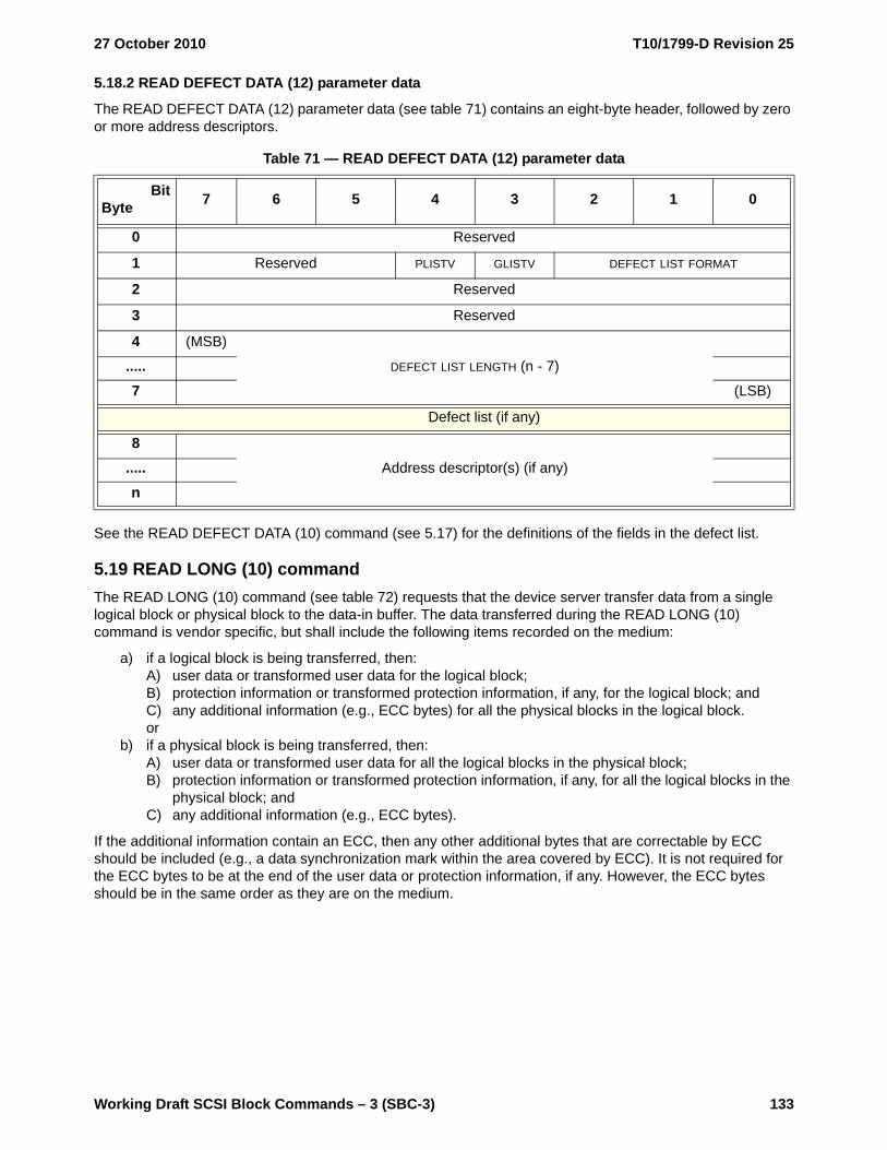
27 October 2010 T10/1799-D Revision 25
Working Draft SCSI Block Commands – 3 (SBC-3) 133
5.18.2 READ DEFECT DATA (12) parameter data
The READ DEFECT DATA (12) parameter data (see table 71) contains an eight-byte header, followed by zero or more address descriptors.
See the READ DEFECT DATA (10) command (see 5.17) for the definitions of the fields in the defect list.
5.19 READ LONG (10) commandThe READ LONG (10) command (see table 72) requests that the device server transfer data from a single logical block or physical block to the data-in buffer. The data transferred during the READ LONG (10) command is vendor specific, but shall include the following items recorded on the medium:
a) if a logical block is being transferred, then:A) user data or transformed user data for the logical block;B) protection information or transformed protection information, if any, for the logical block; andC) any additional information (e.g., ECC bytes) for all the physical blocks in the logical block.or
b) if a physical block is being transferred, then:A) user data or transformed user data for all the logical blocks in the physical block;B) protection information or transformed protection information, if any, for all the logical blocks in the
physical block; andC) any additional information (e.g., ECC bytes).
If the additional information contain an ECC, then any other additional bytes that are correctable by ECC should be included (e.g., a data synchronization mark within the area covered by ECC). It is not required for the ECC bytes to be at the end of the user data or protection information, if any. However, the ECC bytes should be in the same order as they are on the medium.
Table 71 — READ DEFECT DATA (12) parameter data
BitByte 7 6 5 4 3 2 1 0
0 Reserved
1 Reserved PLISTV GLISTV DEFECT LIST FORMAT
2 Reserved
3 Reserved
4 (MSB)
DEFECT LIST LENGTH (n - 7).....7 (LSB)
Defect list (if any)
8Address descriptor(s) (if any).....
n

T10/1799-D Revision 25 27 October 2010
134 Working Draft SCSI Block Commands – 3 (SBC-3)
If a cache contains a more recent version of the specified logical block or physical block, then the device server shall write the logical block or physical block to the medium before reading it. The values in the Read-Write Error Recovery mode page (see 6.4.7) do not apply to this command. The device server may perform retries while processing this command.
The OPERATION CODE field is defined in SPC-4 and is set to the value defined in table 72.
If there is more than one logical block per physical block (i.e., the LOGICAL BLOCKS PER PHYSICAL BLOCK EXPONENT field in the READ CAPACITY (16) data (see 5.16.1) is set to a non-zero value), then:
a) the device server shall support the physical block (PBLOCK) bit;b) a PBLOCK bit set to one specifies that the device server shall return the entire physical block containing
the specified logical block; andc) a PBLOCK bit set to zero specifies that the device server shall return bytes representing only the
specified logical block.
If there are one or more physical blocks per logical block (i.e., the LOGICAL BLOCKS PER PHYSICAL BLOCK EXPONENT field in the READ CAPACITY (16) data (see 5.16.1) is set to zero), and the PBLOCK bit is set to one, then the device server shall terminate the command with CHECK CONDITION status with the sense key set to ILLEGAL REQUEST and the additional sense code set to INVALID FIELD IN CDB.
A correct (CORRCT) bit set to zero specifies that a logical block be read without any correction made by the device server. A CORRCT bit set to zero should result in the device server completing the command with GOOD status unless data is not transferred for some reason other than that the data is non-correctable. In this case the device server shall complete or terminate the command with the appropriate status and sense data. A CORRCT bit set to one specifies that the data be corrected by ECC before being transferred to the data-in buffer.
The LOGICAL BLOCK ADDRESS field specifies an LBA (see 4.5). If the specified LBA exceeds the capacity of the medium, then the device server shall terminate the command with CHECK CONDITION status with the sense key set to ILLEGAL REQUEST and the additional sense code set to LOGICAL BLOCK ADDRESS OUT OF RANGE.
The BYTE TRANSFER LENGTH field specifies the number of bytes of data that shall be read from the specified logical block or physical block and transferred to the data-in buffer. If the BYTE TRANSFER LENGTH field is not set to zero and does not match the available data length, then the device server shall terminate the command with CHECK CONDITION status with the sense key set to ILLEGAL REQUEST and the additional sense code set to INVALID FIELD IN CDB. In the sense data (see 4.16 and SPC-4), the VALID and ILI bits shall each be set to one and the INFORMATION field shall be set to the difference (i.e., residue) of the requested byte transfer length minus the actual available data length in bytes. Negative values shall be indicated by two's complement notation.
Table 72 — READ LONG (10) command
BitByte 7 6 5 4 3 2 1 0
0 OPERATION CODE (3Eh)
1 Reserved PBLOCK CORRCT Obsolete
2 (MSB)
LOGICAL BLOCK ADDRESS.....5 (LSB)
6 Reserved
7 (MSB)BYTE TRANSFER LENGTH
8 (LSB)
9 CONTROL

27 October 2010 T10/1799-D Revision 25
Working Draft SCSI Block Commands – 3 (SBC-3) 135
A BYTE TRANSFER LENGTH field set to zero specifies that no bytes shall be read. This condition shall not be considered an error.
The contents of the CONTROL byte are defined in SAM-4.
5.20 READ LONG (16) commandThe READ LONG (16) command (see table 73) requests that the device server transfer data from a single logical block or physical block to the data-in buffer. The data transferred during the READ LONG (16) command is vendor specific, but shall include the following items recorded on the medium:
a) if a logical block is being transferred, then:A) user data or transformed user data for the logical block;B) protection information or transformed protection information, if any, for the logical block; andC) any additional information (e.g., ECC bytes) for all the physical blocks in the logical block.or
b) if a physical block is being transferred, then:A) user data or transformed user data for all the logical blocks in the physical block;B) protection information or transformed protection information, if any, for all the logical blocks in the
physical block; andC) any additional information (e.g., ECC bytes).
If a cache contains a more recent version of the specified logical block or physical block, then the device server shall write the logical block or physical block to the medium before reading it. The values in the Read-Write Error Recovery mode page (see 6.4.7) do not apply to this command. The device server may perform retries while processing this command. This command is implemented as a service action of the SERVICE ACTION IN operation code (see A.2).
The OPERATION CODE field and SERVICE ACTION field are defined in SPC-4 and shall be set to the value defined in table 73.
See the READ LONG (10) command (see 5.19) for the definitions of the other fields in this command.
Table 73 — READ LONG (16) command
BitByte 7 6 5 4 3 2 1 0
0 OPERATION CODE (9Eh)
1 Reserved SERVICE ACTION (11h)
2 (MSB)
LOGICAL BLOCK ADDRESS.....9 (LSB)
10Reserved
11
12 (MSB)BYTE TRANSFER LENGTH
13 (LSB)
14 Reserved PBLOCK CORRCT
15 CONTROL

T10/1799-D Revision 25 27 October 2010
136 Working Draft SCSI Block Commands – 3 (SBC-3)
5.21 REASSIGN BLOCKS command
5.21.1 REASSIGN BLOCKS command overview
The REASSIGN BLOCKS command (see table 74) requests that the device server reassign defective logical blocks to another area on the medium set aside for this purpose. The device server should also record the location of the defective logical blocks in the GLIST, if supported. This command shall not alter the contents of the PLIST (see 4.11).
The parameter list provided in the data-out buffer contains a defective LBA list that contains the LBAs of the logical blocks to be reassigned. The device server shall reassign the parts of the medium used for each logical block in the defective LBA list. More than one physical block may be reassigned by each LBA. If the device server is able to recover user data and protection information, if any, from the original logical block, then the device server shall write the recovered user data and any protection information to the logical block of the reassigned LBA. If the LBA is unmapped, then the device server shall cause the LBA to become mapped and write the data that was retrieved during a read operation specifying the LBA that was reassigned to the logical block (see 4.7.4.2.1). If the device server is unable to recover user data and protection information, if any, then the device server shall write vendor specific data as the user data and shall write a default value of FFFF_FFFF_FFFF_FFFFh as the protection information, if enabled. The data in all other logical blocks on the medium shall be preserved.
NOTE 18 - The effect of specifying a logical block to be reassigned that previously has been reassigned is to reassign the logical block again. Although not likely, over the life of the medium, a logical block may be assigned to multiple physical block addresses until no more spare locations remain on the medium.
The OPERATION CODE field is defined in SPC-4 and is set to the value defined in table 74.
A long LBA (LONGLBA) bit set to zero specifies that the REASSIGN BLOCKS defective LBA list contains four-byte LBAs. A LONGLBA bit set to one specifies that the REASSIGN BLOCKS defective LBA list contains eight-byte LBAs.
The long list (LONGLIST) bit specifies which parameter list header is used for the data returned by the device server in response to the command (see 5.21.2).
The contents of the CONTROL byte are defined in SAM-4.
Table 74 — REASSIGN BLOCKS command
BitByte 7 6 5 4 3 2 1 0
0 OPERATION CODE (07h)
1 Reserved LONGLBA LONGLIST
2
Reserved3
4
5 CONTROL

27 October 2010 T10/1799-D Revision 25
Working Draft SCSI Block Commands – 3 (SBC-3) 137
5.21.2 REASSIGN BLOCKS parameter list
The REASSIGN BLOCKS parameter list (see table 75) contains a four-byte parameter list header followed by a defective LBA list containing one or more LBAs.
If LONGLIST is set to zero, then the parameter list header is defined in table 76.
If LONGLIST is set to one, then the parameter list header is defined in table 77.
The DEFECT LIST LENGTH field indicates the total length in bytes of the DEFECTIVE LBA LIST field. The DEFECT LIST LENGTH field does not include the parameter list header length and is equal to either:
a) four times the number of LBAs, if the LONGLBA bit is set to zero; orb) eight times the number of LBAs, if the LONGLBA bit is set to one.
The DEFECTIVE LBA LIST field contains a list of defective LBAs. Each LBA is a four-byte field if the LONGLBA bit is set to zero or an eight-byte field if the LONGLBA bit is set to one. The LBAs shall be in ascending order.
If the direct-access block device has insufficient capacity to reassign all of the specified logical blocks, then the device server shall terminate the command with CHECK CONDITION status with the sense key set to HARDWARE ERROR and the additional sense code set to NO DEFECT SPARE LOCATION AVAILABLE.
Table 75 — REASSIGN BLOCKS parameter list
BitByte 7 6 5 4 3 2 1 0
0Parameter list header (see table 76 or table 77).....
3
4DEFECTIVE LBA LIST (if any).....
n
Table 76 — REASSIGN BLOCKS short parameter list header
BitByte 7 6 5 4 3 2 1 0
0Reserved
1
2 (MSB)DEFECT LIST LENGTH
3 (LSB)
Table 77 — REASSIGN BLOCKS long parameter list header
BitByte 7 6 5 4 3 2 1 0
0 (MSB)
DEFECT LIST LENGTH.....3 (LSB)

T10/1799-D Revision 25 27 October 2010
138 Working Draft SCSI Block Commands – 3 (SBC-3)
If the direct-access block device is unable to successfully complete a REASSIGN BLOCKS command, then the device server shall terminate the command with CHECK CONDITION status with the appropriate sense data (see 4.16 and SPC-4). The first LBA not reassigned shall be returned in the COMMAND-SPECIFIC INFORMATION field of the sense data. If information about the first LBA not reassigned is not available, or if all the defects have been reassigned, then the COMMAND-SPECIFIC INFORMATION field shall be set to FFFF_FFFFh if fixed format sense data is being used or FFFF_FFFF_FFFF_FFFFh if descriptor format sense data is being used.
If the REASSIGN BLOCKS command failed due to an unexpected unrecovered read error that would cause the loss of data in a logical block not specified in the defective LBA list, then the LBA of the logical block with the unrecovered read error shall be returned in the INFORMATION field of the sense data and the VALID bit shall be set to one.
NOTE 19 - If the device server terminates the REASSIGN BLOCKS command with CHECK CONDITION status, and the sense data COMMAND-SPECIFIC INFORMATION field contains a valid LBA, then the application client should remove all LBAs from the defective LBA list prior to the one returned in the COMMAND-SPECIFIC INFORMATION field. If the sense key is set to MEDIUM ERROR, and the INFORMATION field contains the valid LBA, then the application client should insert that new defective LBA into the defective LBA list and reissue the REASSIGN BLOCKS command with the new defective LBA list. Otherwise, the application client should perform any corrective action indicated by the sense data and then reissue the REASSIGN BLOCKS command with the new defective LBA list.
5.22 REPORT REFERRALS command
5.22.1 REPORT REFERRALS command overview
The REPORT REFERRALS command requests that the device server send information indicating the user data segment(s) on the logical unit and the SCSI target ports though which those user data segments may be accessed (see 4.25) to the application client. This command shall be supported by a logical unit that reports in the Extended INQUIRY Data VPD page (see SPC-4) that it supports referrals (i.e., the R_SUP bit set to one). This command is implemented as a service action of the SERVICE ACTION IN operation code (see A.2).
The OPERATION CODE field and SERVICE ACTION field are defined in SPC-4 and shall be set to the value defined in table 78.
The LOGICAL BLOCK ADDRESS field specifies an LBA in the first user data segment the device server shall report in the REPORT REFERRALS parameter data.
Table 78 — REPORT REFERRALS command
BitByte 7 6 5 4 3 2 1 0
0 OPERATION CODE (9Eh)
1 Reserved SERVICE ACTION (13h)
2 (MSB)
LOGICAL BLOCK ADDRESS.....
9 (LSB)
10 (MSB)
ALLOCATION LENGTH.....
13 LSB)
14 Reserved ONE_SEG
15 CONTROL
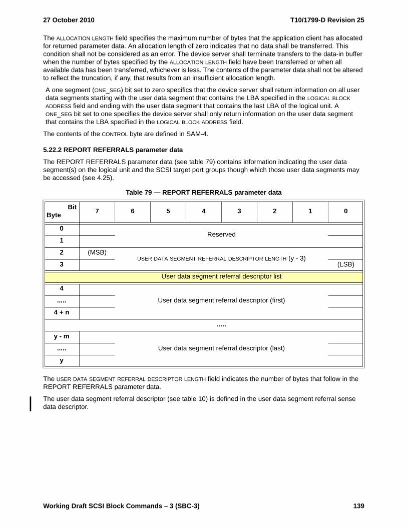
27 October 2010 T10/1799-D Revision 25
Working Draft SCSI Block Commands – 3 (SBC-3) 139
The ALLOCATION LENGTH field specifies the maximum number of bytes that the application client has allocated for returned parameter data. An allocation length of zero indicates that no data shall be transferred. This condition shall not be considered as an error. The device server shall terminate transfers to the data-in buffer when the number of bytes specified by the ALLOCATION LENGTH field have been transferred or when all available data has been transferred, whichever is less. The contents of the parameter data shall not be altered to reflect the truncation, if any, that results from an insufficient allocation length.
A one segment (ONE_SEG) bit set to zero specifics that the device server shall return information on all user data segments starting with the user data segment that contains the LBA specified in the LOGICAL BLOCK ADDRESS field and ending with the user data segment that contains the last LBA of the logical unit. A ONE_SEG bit set to one specifies the device server shall only return information on the user data segment that contains the LBA specified in the LOGICAL BLOCK ADDRESS field.
The contents of the CONTROL byte are defined in SAM-4.
5.22.2 REPORT REFERRALS parameter data
The REPORT REFERRALS parameter data (see table 79) contains information indicating the user data segment(s) on the logical unit and the SCSI target port groups though which those user data segments may be accessed (see 4.25).
The USER DATA SEGMENT REFERRAL DESCRIPTOR LENGTH field indicates the number of bytes that follow in the REPORT REFERRALS parameter data.
The user data segment referral descriptor (see table 10) is defined in the user data segment referral sense data descriptor.
Table 79 — REPORT REFERRALS parameter data
BitByte 7 6 5 4 3 2 1 0
0Reserved
1
2 (MSB)USER DATA SEGMENT REFERRAL DESCRIPTOR LENGTH (y - 3)
3 (LSB)
User data segment referral descriptor list
4
User data segment referral descriptor (first).....
4 + n
.....
y - m
User data segment referral descriptor (last).....
y

T10/1799-D Revision 25 27 October 2010
140 Working Draft SCSI Block Commands – 3 (SBC-3)
5.23 START STOP UNIT commandThe START STOP UNIT command (see table 80) requests that the device server change the power condition of the logical unit (see 4.18) or load or eject the medium. This includes specifying that the device server enable or disable the direct-access block device for medium access operations by controlling power conditions and timers.
If a START STOP UNIT command is being processed by the device server, and a subsequent START STOP UNIT command for which the CDB is validated requests that the logical unit change to a different power condition than was specified by the START STOP UNIT command being processed, then the subsequent START STOP UNIT command shall be terminated with CHECK CONDITION status with the sense key set to NOT READY and the additional sense code set to LOGICAL UNIT NOT READY, START STOP UNIT COMMAND IN PROGRESS.
If any deferred downloaded code has been received as a result of a WRITE BUFFER command (see SPC-4), then that deferred downloaded code shall replace the current operational code.
The OPERATION CODE field is defined in SPC-4 and is set to the value defined in table 80.
If the immediate (IMMED) bit is set to zero, then the device server shall return status after the operation is completed. If the IMMED bit set to one, then the device server shall return status as soon as the CDB has been validated.
Table 80 — START STOP UNIT command
BitByte 7 6 5 4 3 2 1 0
0 OPERATION CODE (1Bh)
1 Reserved IMMED
2 Reserved
3 Reserved POWER CONDITION MODIFIER
4 POWER CONDITION Reserved NO_FLUSH LOEJ START
5 CONTROL

27 October 2010 T10/1799-D Revision 25
Working Draft SCSI Block Commands – 3 (SBC-3) 141
The combinations of values in the POWER CONDITION field and the POWER CONDITION MODIFIER field are defined in table 81. If the POWER CONDITION field is supported and is set to a value other than 0h, then
the device server shall ignore the START bit and the LOEJ bit.
Table 81 — POWER CONDITION and POWER CONDITION MODIFIER field (part 1 of 2)
POWER CONDITION
value
POWER CONDITION
name
POWERCONDITIONMODIFIER
value
Device server action
0h START_ VALID 0h Process the START and LOEJ bits.
1h ACTIVE 0h Cause the logical unit to transition to the active power condition. a b
2h IDLE
0h Cause the logical unit to transition to the idle_a power condition. a b
1h Cause the logical unit to transition to the idle_b power condition. a b c
2h Cause the logical unit to transition to the idle_c power condition. a b d
3h STANDBY0h Cause the logical unit to transition to the standby_z power
condition. a b
1h Cause the logical unit to transition to the standby_y power condition. a b
5h Obsolete 0h to Fh Obsolete
7h LU_CONTROL 0h
Initialize and start all of the idle condition timers that are enabled (see SPC-4), and initialize and start all of the standby condition timers that are enabled (see SPC-4).
a Process the following actions:1) The device server shall comply with any SCSI transport protocol specific power condition transition
restrictions (e.g., the NOTIFY (ENABLE SPINUP) requirement (see SPL));2) the logical unit shall transition to the specified power condition; and3) the device server shall disable all of the idle condition timers that are enabled (see SPC-4) and
disable all of the standby condition timers that are enabled (see SPC-4) until another START STOP UNIT command is processed that returns control of the power condition to the logical unit or a logical unit reset occurs.
b If a timer for a background scan operation expires, or a device specific event occurs, then the logical unit shall not leave this power condition to perform the background function associated with the timer or event.
c The device server shall cause the direct access block device to increase its tolerance of external physical forces (e.g., causes a device that has movable read/write heads to move those heads to a safe position).
d The device server shall cause the direct access block device to increase its tolerance of external physical forces and reduce its power consumption to use less power than when the logical unit is in the idle_b power condition (e.g., cause a device that has rotating media to rotate the media at a lower rpm).
e If the specified timer is supported and enabled, then the device server shall:a) force the specified timer to be set to zero, which may cause the logical unit to transition to the
specified power condition;b) initialize and start all of the idle condition timers that are enabled (see SPC-4); andc) initialize and start all of the standby condition timers that are enabled (see SPC-4),otherwise the device server shall terminate the START STOP UNIT command with CHECK CONDITION status with the sense key set to ILLEGAL REQUEST and the additional sense code set to INVALID FIELD IN CDB.

T10/1799-D Revision 25 27 October 2010
142 Working Draft SCSI Block Commands – 3 (SBC-3)
If the START STOP UNIT command specifies a power condition that conflicts with an operation in progress (e.g., a background self test), then, after the START STOP UNIT command completes with GOOD status, the logical unit may not be in the power condition that was requested by the command.
It is not an error to specify that the logical unit transition to its current power condition.
If no START STOP UNIT command is being processed by the device server, then the device server shall process any received START STOP UNIT command.
If a START STOP UNIT command is being processed by the device server and a subsequent START STOP UNIT command for which the CDB is validated requests that the logical unit change to a different power condition than was specified by the START STOP UNIT command being processed, then the subsequent START STOP UNIT command shall be terminated with CHECK CONDITION status with the sense key set to NOT READY and the additional sense code set to LOGICAL UNIT NOT READY, START STOP UNIT COMMAND IN PROGRESS.
Ah FORCE_ IDLE_0
0h Force the idle_a condition timer to be set to zero. e
1h Force the idle_b condition timer to be set to zero. e
2h Force the idle_c condition timer to be set to zero. e
BhFORCE_
STANDBY_0
0h Force the standby_z condition timer to be set to zero. e
1h Force the standby_y condition timer to be set to zero. e
All other combinations Reserved
Table 81 — POWER CONDITION and POWER CONDITION MODIFIER field (part 2 of 2)
POWER CONDITION
value
POWER CONDITION
name
POWERCONDITIONMODIFIER
value
Device server action
a Process the following actions:1) The device server shall comply with any SCSI transport protocol specific power condition transition
restrictions (e.g., the NOTIFY (ENABLE SPINUP) requirement (see SPL));2) the logical unit shall transition to the specified power condition; and3) the device server shall disable all of the idle condition timers that are enabled (see SPC-4) and
disable all of the standby condition timers that are enabled (see SPC-4) until another START STOP UNIT command is processed that returns control of the power condition to the logical unit or a logical unit reset occurs.
b If a timer for a background scan operation expires, or a device specific event occurs, then the logical unit shall not leave this power condition to perform the background function associated with the timer or event.
c The device server shall cause the direct access block device to increase its tolerance of external physical forces (e.g., causes a device that has movable read/write heads to move those heads to a safe position).
d The device server shall cause the direct access block device to increase its tolerance of external physical forces and reduce its power consumption to use less power than when the logical unit is in the idle_b power condition (e.g., cause a device that has rotating media to rotate the media at a lower rpm).
e If the specified timer is supported and enabled, then the device server shall:a) force the specified timer to be set to zero, which may cause the logical unit to transition to the
specified power condition;b) initialize and start all of the idle condition timers that are enabled (see SPC-4); andc) initialize and start all of the standby condition timers that are enabled (see SPC-4),otherwise the device server shall terminate the START STOP UNIT command with CHECK CONDITION status with the sense key set to ILLEGAL REQUEST and the additional sense code set to INVALID FIELD IN CDB.

27 October 2010 T10/1799-D Revision 25
Working Draft SCSI Block Commands – 3 (SBC-3) 143
If a START STOP UNIT command is being processed by the device server and a subsequent START STOP UNIT command for which the CDB is validated requests that the logical unit change to the same power condition that was specified by the START STOP UNIT command being processed, then the subsequent command shall be processed.
If the NO_FLUSH bit is set to zero, then logical units that contain cache shall write all cached logical blocks to the medium (e.g., as they would do in response to a SYNCHRONIZE CACHE command (see 5.24 and 5.25) with the SYNC_NV bit set to zero, the LOGICAL BLOCK ADDRESS field set to zero, and the NUMBER OF LOGICAL BLOCKS field set to zero) prior to entering into any power condition that prevents accessing the medium (e.g., before the rotating media spindle motor is stopped during transition to the stopped power condition). If the NO_FLUSH bit is set to one, then cached logical blocks should not be written to the medium by the logical unit prior to entering into any power condition that prevents accessing the medium.
If the load eject (LOEJ) bit is set to zero, then the logical unit shall take no action regarding loading or ejecting the medium. If the LOEJ bit is set to one, then the logical unit shall unload the medium if the START bit is set to zero. If the LOEJ bit is set to one, then the logical unit shall load the medium if the START bit is set to one. If the POWER CONDITION field is supported and is set to a value other than 0h, then the device server shall ignore the the LOEJ bit.
If the START bit is set to zero, then the device server shall:
a) cause the logical unit to transition to the stopped power condition;b) stop any idle condition timer that is enabled (see SPC-4); andc) stop any standby condition timer that is enabled (see SPC-4).
If the START bit set to one, then the device server shall:
1) comply with requirements defined in SCSI transport protocol standards (e.g., the NOTIFY (ENABLE SPINUP) requirement (see SPL));
2) cause the logical unit to transition to the active power condition;3) initialize and start any idle condition timer that is enabled; and4) initialize and start any standby condition timer that is enabled.
If the POWER CONDITION field is supported and is set to a value other than 0h, then the device server shall ignore the START bit.
The contents of the CONTROL byte are defined in SAM-4.

T10/1799-D Revision 25 27 October 2010
144 Working Draft SCSI Block Commands – 3 (SBC-3)
5.24 SYNCHRONIZE CACHE (10) commandThe SYNCHRONIZE CACHE (10) command (see table 82) requests that the device server ensure that the specified logical blocks have their most recent data values recorded in non-volatile cache and/or on the medium, based on the SYNC_NV bit. Logical blocks include user data and, if the medium is formatted with protection information enabled, protection information. Logical blocks may or may not be removed from volatile cache and non-volatile cache as a result of the synchronize cache operation.
The OPERATION CODE field is defined in SPC-4 and is set to the value defined in table 82.
See the PRE-FETCH (10) command (see 5.7) for the definition of the LOGICAL BLOCK ADDRESS field.
See the PRE-FETCH (10) command (see 5.7) and 4.20 for the definition of the GROUP NUMBER field.
The SYNC_NV bit (see table 83) specifies whether the device server is required to synchronize volatile and non-volatile caches.
An immediate (IMMED) bit set to zero specifies that the device server shall not return status until the operation has been completed. An IMMED bit set to one specifies that the device server shall return status as soon as the CDB has been validated. If the IMMED bit is set to one, and the device server does not support the IMMED bit, then the device server shall terminate the command with CHECK CONDITION status with the sense key set to ILLEGAL REQUEST and the additional sense code set to INVALID FIELD IN CDB.
The NUMBER OF LOGICAL BLOCKS field specifies the number of logical blocks that shall be synchronized, starting with the logical block specified by the LOGICAL BLOCK ADDRESS field. A NUMBER OF LOGICAL BLOCKS field set to zero specifies that all logical blocks starting with the one specified in the LOGICAL BLOCK ADDRESS field to the last logical block on the medium shall be synchronized. If the LBA plus the number of logical blocks exceeds the capacity of the medium, then the device server shall terminate the command with CHECK
Table 82 — SYNCHRONIZE CACHE (10) command
BitByte 7 6 5 4 3 2 1 0
0 OPERATION CODE (35h)
1 Reserved SYNC_NV IMMED Obsolete
2 (MSB)
LOGICAL BLOCK ADDRESS.....5 (LSB)
6 Reserved GROUP NUMBER
7 (MSB)NUMBER OF LOGICAL BLOCKS
8 (LSB)
9 CONTROL
Table 83 — SYNC_NV bit
CodeDevice server requirement to synchronize logical blocks currently in the
Volatile cache Non-volatile cache
0 Device server shall synchronize to the medium. Device server shall synchronize to the medium.
1
If a non-volatile cache is present, then the device server shall synchronize to non-volatile cache or the medium. If a non-volatile cache is not present, then the device server shall synchronize to the medium.
No requirement.

27 October 2010 T10/1799-D Revision 25
Working Draft SCSI Block Commands – 3 (SBC-3) 145
CONDITION status with the sense key set to ILLEGAL REQUEST and the additional sense code set to LOGICAL BLOCK ADDRESS OUT OF RANGE.
A logical block within the range that is not in cache is not considered an error.
The contents of the CONTROL byte are defined in SAM-4.
5.25 SYNCHRONIZE CACHE (16) commandThe SYNCHRONIZE CACHE (16) command (see table 84) requests that the device server ensure that the specified logical blocks have their most recent data values recorded in non-volatile cache and/or on the medium, based on the SYNC_NV bit. Logical blocks include user data and, if the medium is formatted with protection information enabled, protection information. Logical blocks may or may not be removed from volatile cache and non-volatile cache as a result of the synchronize cache operation.
The OPERATION CODE field is defined in SPC-4 and is set to the value defined in table 84.
See the SYNCHRONIZE CACHE (10) command (see 5.24) for the definitions of the other fields in this command.
Table 84 — SYNCHRONIZE CACHE (16) command
BitByte 7 6 5 4 3 2 1 0
0 OPERATION CODE (91h)
1 Reserved SYNC_NV IMMED Reserved
2 (MSB)
LOGICAL BLOCK ADDRESS.....9 (LSB)
10 (MSB)
NUMBER OF LOGICAL BLOCKS.....13 (LSB)
14 Reserved GROUP NUMBER
15 CONTROL

T10/1799-D Revision 25 27 October 2010
146 Working Draft SCSI Block Commands – 3 (SBC-3)
5.26 UNMAP command
5.26.1 UNMAP command overview
The UNMAP command (see table 85) requests that the device server cause one or more LBAs to be unmapped. The UNMAP command may be implemented by device servers in logical units that support logical block provisioning management (see 4.7.3).
The OPERATION CODE field is defined in SPC-4 and is set to the value defined in table 88.
For a thin provisioned logical unit (see 4.7.3.3):
a) an ANCHOR bit set to zero specifies that any LBA on which an unmap operation is performed shall become deallocated: and
b) an ANCHOR bit set to one specifies that any LBA on which an unmap operation is performed shall become anchored.
For a resource provisioned logical unit (see 4.7.3.2), any LBA on which an unmap operation is performed shall become anchored (i.e., the command is processed as if the ANCHOR bit is set to one).
If the ANCHOR bit is set to one, and the ANC_SUP bit in the Logical Block Provisioning VPD page (see 6.5.4) is set to zero, then the device server shall terminate the command with CHECK CONDITION status with the sense key set to ILLEGAL REQUEST and the additional sense code set to INVALID FIELD IN CDB.
See the PRE-FETCH (10) command (see 5.7) and 4.20 for the definition of the GROUP NUMBER field.
The PARAMETER LIST LENGTH field specifies the length in bytes of the UNMAP parameter data that shall be sent from the application client to the device server. A PARAMETER LIST LENGTH set to zero specifies that no data shall be sent.
The contents of the CONTROL byte are defined in SAM-4.
5.26.2 UNMAP parameter list
The UNMAP parameter list (see table 86) contains the data sent by an application client along with an UNMAP command. Included in the data are an UNMAP parameter list header and block descriptors for LBA extents to be processed by the device server for the UNMAP command. The LBAs specified in the block descriptors may contain overlapping extents, and may be in any order.
Table 85 — UNMAP command
BitByte 7 6 5 4 3 2 1 0
0 OPERATION CODE (42h)
1 Reserved ANCHOR
2Reserved.....
5
6 Reserved GROUP NUMBER
7 (MSB)PARAMETER LIST LENGTH
8 (LSB)
9 CONTROL

27 October 2010 T10/1799-D Revision 25
Working Draft SCSI Block Commands – 3 (SBC-3) 147
If the ANCHOR bit in the CDB is set to zero, and the logical unit is thin provisioned (see 4.7.3.3), then each specified LBA should become deallocated and may become anchored.
If:
a) the ANCHOR bit in the CDB is set to one, and the ANC_SUP field in the Logical Block Provisioning VPD page (see 6.5.4) is set to one; or
b) the logical unit is resource provisioned,
then, for each specified LBA:
c) if the LBA is mapped, then that LBA should become anchored (see 4.7.4.2.3), and the LBA shall not become deallocated;
d) if the LBA is deallocated, then that LBA shall become anchored (see 4.7.4.3.3). If a lack of LBA mapping resources prevents the LBA from becoming anchored, then the command shall be terminated as described in 4.7.3.7; or
e) if the LBA is anchored, then that LBA shall remain anchored.
The UNMAP DATA LENGTH field specifies the length in bytes of the following data that is available to be transferred from the data-out buffer. The unmap data length does not include the number of bytes in the UNMAP DATA LENGTH field.
The UNMAP BLOCK DESCRIPTOR DATA LENGTH field specifies the length in bytes of the UNMAP block descriptors that are available to be transferred from the data-out buffer. The unmap block descriptor data length should be a multiple of 16. If the unmap block descriptor data length is not a multiple of 16, then the last unmap block descriptor is incomplete and shall be ignored. If the UNMAP BLOCK DESCRIPTOR DATA LENGTH is set to zero, then no unmap block descriptors are included in the UNMAP parameter data. This condition shall not be considered an error.
Table 86 — UNMAP parameter list
BitByte 7 6 5 4 3 2 1 0
0 (MSB)UNMAP DATA LENGTH (n-1)
1 (LSB)
2 (MSB)UNMAP BLOCK DESCRIPTOR DATA LENGTH (n-7)
3 (LSB)
4Reserved.....
7
UNMAP block descriptors
8UNMAP block descriptor (first) (see table 87).....
23.....
n-15UNMAP block descriptor (last) (see table 87).....
n

T10/1799-D Revision 25 27 October 2010
148 Working Draft SCSI Block Commands – 3 (SBC-3)
Table 87 defines an UNMAP block descriptor.
The UNMAP LOGICAL BLOCK ADDRESS field contains the first LBA of the UNMAP block descriptor to be unmapped.
The NUMBER OF LOGICAL BLOCKS field contains the number of LBAs to be unmapped beginning with the LBA specified by the UNMAP LOGICAL BLOCK ADDRESS field.
If the NUMBER OF LOGICAL BLOCKS is set to zero, then no LBAs shall be unmapped for this UNMAP block descriptor. This condition shall not be considered an error.
If the LBA specified by the UNMAP LOGICAL BLOCK ADDRESS field plus the number of logical blocks exceeds the capacity of the medium, then the device server shall terminate the command with CHECK CONDITION status with the sense key set to ILLEGAL REQUEST and the additional sense code set to LOGICAL BLOCK ADDRESS OUT OF RANGE.
If the total number of logical blocks specified in the UNMAP block descriptor data exceeds the value indicated in the MAXIMUM UNMAP LBA COUNT field in the Block Limits VPD page (see 6.5.3), or if the number of UNMAP block descriptors exceeds the value of the MAXIMUM UNMAP BLOCK DESCRIPTOR COUNT field in the Block Limits VPD page, then the device server shall terminate the command with CHECK CONDITION status with the sense key set to ILLEGAL REQUEST and the additional sense code set to INVALID FIELD IN PARAMETER LIST.
Table 87 — UNMAP block descriptor
BitByte 7 6 5 4 3 2 1 0
0 (MSB)
UNMAP LOGICAL BLOCK ADDRESS.....7 (LSB)
8 (MSB)
NUMBER OF LOGICAL BLOCKS....
11 (LSB)
12Reserved.....
15

27 October 2010 T10/1799-D Revision 25
Working Draft SCSI Block Commands – 3 (SBC-3) 149
5.27 VERIFY (10) commandThe VERIFY (10) command (see table 88) requests that the device server verify the specified logical block(s) on the medium. Each logical block includes user data and may include protection information, based on the VRPROTECT field and the medium format.
Logical units that contain cache shall write referenced cached logical blocks to the medium for the logical unit (e.g., as they would do in response to a SYNCHRONIZE CACHE command (see 5.24 and 5.25) with the SYNC_NV bit set to zero, the LOGICAL BLOCK ADDRESS field set to the value of the VERIFY command’s LOGICAL BLOCK ADDRESS field, and the NUMBER OF BLOCKS field set to the value of the VERIFY command’s VERIFICATION LENGTH field).
If the Verify Error Recovery mode page (see 6.4.8) is implemented, then the current settings in that page specify the verification criteria. If the Verify Error Recovery mode page is not implemented, then the verification criteria is vendor specific.
The OPERATION CODE field is defined in SPC-4 and is set to the value defined in table 88.
See the READ (10) command (see 5.11) for the definition of the DPO bit. See the PRE-FETCH (10) command (see 5.7) for the definition of the LOGICAL BLOCK ADDRESS field. See the PRE-FETCH (10) command (see 5.7) and 4.20 for the definition of the GROUP NUMBER field.
If the byte check (BYTCHK) bit is set to zero, then, for any mapped LBA specified by the command, the device server shall:
a) perform a medium verification with no data comparison and not transfer any data from the data-out buffer; and
b) check protection information read from the medium based on the VRPROTECT field as described in table 89.
If the byte check (BYTCHK) bit is set to zero, then, for any unmapped LBA specified by the command, the device server shall take no action and consider the LBA as having been verified without error.
If the BYTCHK bit is set to one, then, for any mapped LBA specified by the command, the device server shall:
a) perform a byte-by-byte comparison of user data read from the medium and user data transferred from the data-out buffer;
b) check protection information read from the medium based on the VRPROTECT field as described in table 90;
c) check protection information transferred from the data-out buffer based on the VRPROTECT field as described in table 91; and
Table 88 — VERIFY (10) command
BitByte 7 6 5 4 3 2 1 0
0 OPERATION CODE (2Fh)
1 VRPROTECT DPO Reserved BYTCHK Obsolete
2 (MSB)
LOGICAL BLOCK ADDRESS.....5 (LSB)
6 Restricted for MMC-6 Reserved GROUP NUMBER
7 (MSB)VERIFICATION LENGTH
8 (LSB)
9 CONTROL

T10/1799-D Revision 25 27 October 2010
150 Working Draft SCSI Block Commands – 3 (SBC-3)
d) perform a byte-by-byte comparison of protection information read from the medium and transferred from the data-out buffer based on the VRPROTECT field as described in table 92.
If the BYTCHK bit is set to one, then, if any unmapped LBA is specified by the command, the device server shall terminate the command with CHECK CONDITION status with the sense key set to MISCOMPARE and the additional sense code set to MISCOMPARE VERIFY OF UNMAPPED LBA.
The order of the user data and protection information checks and comparisons is vendor specific.
If a byte-by-byte comparison is unsuccessful for any reason, then the device server shall terminate the command with CHECK CONDITION status with the sense key set to MISCOMPARE and the additional sense code set to the appropriate value for the condition.
The VERIFICATION LENGTH field specifies the number of contiguous logical blocks that shall be verified, starting with the logical block specified by the LOGICAL BLOCK ADDRESS field. If the BYTCHK bit is set to one, then the VERIFICATION LENGTH field also specifies the number of logical blocks that the device server shall transfer from the data-out buffer. A VERIFICATION LENGTH field set to zero specifies that no logical blocks shall be verified. This condition shall not be considered as an error. Any other value specifies the number of logical blocks that shall be verified. If the LBA plus the verification length exceeds the capacity of the medium, then the device server shall terminate the command with CHECK CONDITION status with the sense key set to ILLEGAL REQUEST and the additional sense code set to LOGICAL BLOCK ADDRESS OUT OF RANGE. The VERIFICATION LENGTH field is constrained by the MAXIMUM TRANSFER LENGTH field in the Block Limits VPD page (see 6.5.3).
The contents of the CONTROL byte are defined in SAM-4.
If the BYTCHK bit is set to zero, then the device server shall check the protection information read from the medium based on the VRPROTECT field as described in table 89. All footnotes for table 89 are at the end of the table.
Table 89 — VRPROTECT field with BYTCHK set to zero – checking protection information read from the medium (part 1 of 3)
Code
Logical unit formatted
with protection
information
Field in protection
information g
Extended INQUIRY Data VPD page bit
value fIf check fails d e, additional sense code
000bYes i
LOGICAL BLOCK GUARD
GRD_CHK = 1 LOGICAL BLOCK GUARD CHECK FAILEDGRD_CHK = 0 No check performed
LOGICAL BLOCK
APPLICATION TAG
APP_CHK = 1 c LOGICAL BLOCK APPLICATION TAG CHECK FAILED
APP_CHK = 0 No check performed
LOGICAL BLOCK
REFERENCE TAG
REF_CHK = 1 h LOGICAL BLOCK REFERENCE TAG CHECK FAILED
REF_CHK = 0 No check performed
No No protection information on the medium to check. Only user data is checked.

27 October 2010 T10/1799-D Revision 25
Working Draft SCSI Block Commands – 3 (SBC-3) 151
001b101b b
Yes
LOGICAL BLOCK GUARD
GRD_CHK = 1 LOGICAL BLOCK GUARD CHECK FAILEDGRD_CHK = 0 No check performed
LOGICAL BLOCK
APPLICATION TAG
APP_CHK = 1 c LOGICAL BLOCK APPLICATION TAG CHECK FAILED
APP_CHK = 0 No check performed
LOGICAL BLOCK
REFERENCE TAG
REF_CHK = 1 h LOGICAL BLOCK REFERENCE TAG CHECK FAILED
REF_CHK = 0 No check performed
No Error condition a
010b bYes
LOGICAL BLOCK GUARD
No check performed
LOGICAL BLOCK
APPLICATION TAG
APP_CHK = 1 c LOGICAL BLOCK APPLICATION TAG CHECK FAILED
APP_CHK = 0 No check performed
LOGICAL BLOCK
REFERENCE TAG
REF_CHK = 1 h LOGICAL BLOCK REFERENCE TAG CHECK FAILED
REF_CHK = 0 No check performed
No Error condition a
011b bYes
LOGICAL BLOCK GUARD
No check performed
LOGICAL BLOCK
APPLICATION TAG
No check performed
LOGICAL BLOCK
REFERENCE TAG
No check performed
No Error condition a
100b bYes
LOGICAL BLOCK GUARD
GRD_CHK = 1 LOGICAL BLOCK GUARD CHECK FAILEDGRD_CHK = 0 No check performed
LOGICAL BLOCK
APPLICATION TAG
No check performed
LOGICAL BLOCK
REFERENCE TAG
No check performed
No Error condition a
Table 89 — VRPROTECT field with BYTCHK set to zero – checking protection information read from the medium (part 2 of 3)
Code
Logical unit formatted
with protection
information
Field in protection
information g
Extended INQUIRY Data VPD page bit
value fIf check fails d e, additional sense code

T10/1799-D Revision 25 27 October 2010
152 Working Draft SCSI Block Commands – 3 (SBC-3)
110b to
111bReserved
a If a logical unit supports protection information (see 4.19) but has not been formatted with protection information, then the device server shall terminate a command specifying a verify operation to the logical unit with CHECK CONDITION status with the sense key set to ILLEGAL REQUEST and the additional sense code set to INVALID FIELD IN CDB.
b If the logical unit does not support protection information, then the device server should terminate the requested command with CHECK CONDITION status with the sense key set to ILLEGAL REQUEST and the additional sense code set to INVALID FIELD IN CDB.
c If the device server has knowledge of the contents of the LOGICAL BLOCK APPLICATION TAG field, then the device server shall check each logical block application tag. If the ATO bit in the Control mode page (see SPC-4) is set to one, then this knowledge is acquired from:a) the EXPECTED LOGICAL BLOCK APPLICATION TAG field and the LOGICAL BLOCK APPLICATION TAG MASK
field in the CDB, if a VERIFY (32) command (see 5.30) is received by the device server;b) the Application Tag mode page (see 6.4.3), if a command other than VERIFY (32) is received by the
device server, and the ATMPE bit in the Control mode page (see SPC-4) is set to one; orc) a method not defined by this standard, if a command other than VERIFY (32) is received by the
device server, and the ATMPE bit is set to zero.d If the device server terminates the command with CHECK CONDITION status, then the device server
shall set the sense key to ABORTED COMMAND.e If multiple errors occur while the device server is processing the command, then the selection by the
device server of which error to report is not defined by this standard.f See the Extended INQUIRY Data VPD page (see SPC-4) for the definitions of the GRD_CHK bit, the
APP_CHK bit, and the REF_CHK bits.g If the device server detects:
a) a LOGICAL BLOCK APPLICATION TAG field set to FFFFh and type 1 protection (see 4.19.2.3) or type 2 protection (see 4.19.2.4) is enabled; or
b) a LOGICAL BLOCK APPLICATION TAG field set to FFFFh, LOGICAL BLOCK REFERENCE TAG field set to FFFF_FFFFh, and type 3 protection (see 4.19.2.5) is enabled,
then the device server shall not check any protection information in the associated protection information interval.
h If type 1 protection is enabled, then the device server shall check each logical block reference tag by comparing it to the lower four bytes of the LBA associated with the logical block. If type 2 protection or type 3 protection is enabled, and the device server has knowledge of the contents of the LOGICAL BLOCK REFERENCE TAG field, then the device server shall check the logical block reference tag. If type 2 protection is enabled, then this knowledge may be acquired through the EXPECTED INITIAL LOGICAL BLOCK REFERENCE TAG field in a VERIFY (32) command (see 5.30). If type 3 protection is enabled, then the method for acquiring this knowledge is not defined by this standard.
i If the DPICZ bit in the Control mode page (see SPC-4) is set to one, then protection information shall not be checked.
Table 89 — VRPROTECT field with BYTCHK set to zero – checking protection information read from the medium (part 3 of 3)
Code
Logical unit formatted
with protection
information
Field in protection
information g
Extended INQUIRY Data VPD page bit
value fIf check fails d e, additional sense code

27 October 2010 T10/1799-D Revision 25
Working Draft SCSI Block Commands – 3 (SBC-3) 153
If the BYTCHK bit is set to one, then the device server shall check the protection information read from the medium based on the VRPROTECT field as described in table 90. All footnotes for table 90 are at the end of the table.
Table 90 — VRPROTECT field with BYTCHK set to one – checking protection information read from the medium (part 1 of 2)
Code
Logical unit formatted
with protection
information
Field in protection
information g
Extended INQUIRY Data VPD page bit
value fIf check fails d e, additional sense code
000bYes i
LOGICAL BLOCK GUARD
GRD_CHK = 1 LOGICAL BLOCK GUARD CHECK FAILED
GRD_CHK = 0 No check performed
LOGICAL BLOCK APPLICATION TAG
APP_CHK = 1 c g LOGICAL BLOCK APPLICATION TAG CHECK FAILED
APP_CHK = 0 No check performed
LOGICAL BLOCK REFERENCE TAG
REF_CHK = 1 h LOGICAL BLOCK REFERENCE TAG CHECK FAILED
REF_CHK = 0 No check performedNo No protection information on the medium available to check
001b010b011b100b
101b b
Yes
LOGICAL BLOCK GUARD
No check performed
LOGICAL BLOCK APPLICATION TAG
No check performed
LOGICAL BLOCK REFERENCE TAG
No check performed
No Error condition a
110b to
111bReserved

T10/1799-D Revision 25 27 October 2010
154 Working Draft SCSI Block Commands – 3 (SBC-3)
a If a logical unit supports protection information (see 4.19) but has not been formatted with protection information, then the device server shall terminate a command specifying a verify operation to the logical unit with CHECK CONDITION status with the sense key set to ILLEGAL REQUEST and the additional sense code set to INVALID FIELD IN CDB.
b If the logical unit does not support protection information, then the device server should terminate the requested command with CHECK CONDITION status with the sense key set to ILLEGAL REQUEST and the additional sense code set to INVALID FIELD IN CDB.
c If the device server has knowledge of the contents of the LOGICAL BLOCK APPLICATION TAG field, then the device server shall check each logical block application tag. If the ATO bit in the Control mode page (see SPC-4) is set to one, then this knowledge is acquired from:a) the EXPECTED LOGICAL BLOCK APPLICATION TAG field and the LOGICAL BLOCK APPLICATION TAG MASK
field in the CDB, if a VERIFY (32) command (see 5.30) is received by the device server;b) the Application Tag mode page (see 6.4.3), if a command other than VERIFY (32) is received by the
device server, and the ATMPE bit in the Control mode page (see SPC-4) is set to one; orc) a method not defined by this standard, if a command other than VERIFY (32) is received by the
device server, and the ATMPE bit is set to zero.d If the device server terminates the command with CHECK CONDITION status, then the device server
shall set the sense key to ABORTED COMMAND.e If multiple errors occur while the device server is processing the command, then the selection by the
device server of which error to report is not defined by this standard.f See the Extended INQUIRY Data VPD page (see SPC-4) for the definitions of the GRD_CHK bit, the
APP_CHK bit, and the REF_CHK bit.g If the device server detects:
a) a LOGICAL BLOCK APPLICATION TAG field set to FFFFh and type 1 protection (see 4.19.2.3) or type 2 protection (see 4.19.2.4) is enabled; or
b) a LOGICAL BLOCK APPLICATION TAG field set to FFFFh, LOGICAL BLOCK REFERENCE TAG field set to FFFF_FFFFh, and type 3 protection (see 4.19.2.5) is enabled,
then the device server shall not check any protection information in the associated protection information interval.
h If type 1 protection is enabled, then the device server shall check each logical block reference tag by comparing it to the lower four bytes of the LBA associated with the logical block. If type 2 protection or type 3 protection is enabled, and the device server has knowledge of the contents of the LOGICAL BLOCK REFERENCE TAG field, then the device server shall check the logical block reference tag. If type 2 protection is enabled, then this knowledge may be acquired through the EXPECTED INITIAL LOGICAL BLOCK REFERENCE TAG field in a VERIFY (32) command (see 5.30). If type 3 protection is enabled, then the method for acquiring this knowledge is not defined by this standard.
i If the DPICZ bit in the Control mode page (see SPC-4) is set to one, then protection information shall not be checked.
Table 90 — VRPROTECT field with BYTCHK set to one – checking protection information read from the medium (part 2 of 2)
Code
Logical unit formatted
with protection
information
Field in protection
information g
Extended INQUIRY Data VPD page bit
value fIf check fails d e, additional sense code

27 October 2010 T10/1799-D Revision 25
Working Draft SCSI Block Commands – 3 (SBC-3) 155
If the BYTCHK bit is set to one, then the device server shall check the protection information transferred from the data-out buffer based on the VRPROTECT field as described in table 91. All footnotes for table 91 are at the end of the table.
Table 91 — VRPROTECT field with BYTCHK set to one – checking protection information from the data-out buffer (part 1 of 2)
Code
Logical unit formatted
with protection
information
Field in protection
information
Device server check
If check fails d e, additional sense code
000b Yes No protection information received from application client to checkNo No protection information received from application client to check
001b bYes
LOGICAL BLOCK GUARD
Shall LOGICAL BLOCK GUARD CHECK FAILED
LOGICAL BLOCK APPLICATION TAG
May c LOGICAL BLOCK APPLICATION TAG CHECK FAILED
LOGICAL BLOCK REFERENCE TAG
Shall (except for type 3) f
LOGICAL BLOCK REFERENCE TAG CHECK FAILED
No Error condition a
010b bYes
LOGICAL BLOCK GUARD
Shall not No check performed
LOGICAL BLOCK APPLICATION TAG
May c LOGICAL BLOCK APPLICATION TAG CHECK FAILED
LOGICAL BLOCK REFERENCE TAG
May f LOGICAL BLOCK REFERENCE TAG CHECK FAILED
No Error condition a
011b bYes
LOGICAL BLOCK GUARD
Shall not No check performed
LOGICAL BLOCK APPLICATION TAG
Shall not No check performed
LOGICAL BLOCK REFERENCE TAG
Shall not No check performed
No Error condition a
100b bYes
LOGICAL BLOCK GUARD
Shall LOGICAL BLOCK GUARD CHECK FAILED
LOGICAL BLOCK APPLICATION TAG
Shall not No check performed
LOGICAL BLOCK REFERENCE TAG
Shall not No check performed
No Error condition a

T10/1799-D Revision 25 27 October 2010
156 Working Draft SCSI Block Commands – 3 (SBC-3)
101b bYes
LOGICAL BLOCK GUARD
Shall LOGICAL BLOCK GUARD CHECK FAILED
LOGICAL BLOCK APPLICATION TAG
May c LOGICAL BLOCK APPLICATION TAG CHECK FAILED
LOGICAL BLOCK REFERENCE TAG
May f LOGICAL BLOCK REFERENCE TAG CHECK FAILED
No Error condition a
110b to
111bReserved
a If a logical unit supports protection information (see 4.19) but has not been formatted with protection information, then the device server shall terminate a command specifying a verify operation to the logical unit with CHECK CONDITION status with the sense key set to ILLEGAL REQUEST and the additional sense code set to INVALID FIELD IN CDB.
b If the logical unit does not support protection information, then the device server should terminate the requested command with CHECK CONDITION status with the sense key set to ILLEGAL REQUEST and the additional sense code set to INVALID FIELD IN CDB.
c If the device server has knowledge of the contents of the LOGICAL BLOCK APPLICATION TAG field, and the ATO bit is set to one in the Control mode page (see SPC-4), then the device server may check each logical block application tag. If the ATO bit is set to one, then this knowledge is acquired from:a) the EXPECTED LOGICAL BLOCK APPLICATION TAG field and the LOGICAL BLOCK APPLICATION TAG MASK
field in the CDB, if a VERIFY (32) command (see 5.30) is received by the device server;b) the Application Tag mode page (see 6.4.3), if a command other than VERIFY (32) is received by the
device server, and the ATMPE bit in the Control mode page (see SPC-4) is set to one; orc) a method not defined by this standard, if a command other than VERIFY (32) is received by the
device server, and the ATMPE bit is set to zero.d If the device server terminates the command with CHECK CONDITION status, then the device server
shall set the sense key to ABORTED COMMAND.e If multiple errors occur while the device server is processing the command, then the selection by the
device server of which error to report is not defined by this standard.f If type 1 protection is enabled, then the device server shall check the logical block reference tag by
comparing it to the lower four bytes of the LBA associated with the logical block. If type 2 protection is enabled, and the device server has knowledge of the contents of the LOGICAL BLOCK REFERENCE TAG field, then the device server shall check each logical block reference tag. If type 2 protection is enabled, then this knowledge may be acquired through the EXPECTED INITIAL LOGICAL BLOCK REFERENCE TAG field in a VERIFY (32) command (see 5.30). If type 3 protection is enabled, the ATO bit is set to one in the Control mode page (see SPC-4), and the device server has knowledge of the contents of the LOGICAL BLOCK REFERENCE TAG field, then the device server may check each logical block reference tag. If type 3 protection is enabled, then the method for acquiring this knowledge is not defined by this standard.
Table 91 — VRPROTECT field with BYTCHK set to one – checking protection information from the data-out buffer (part 2 of 2)
Code
Logical unit formatted
with protection
information
Field in protection
information
Device server check
If check fails d e, additional sense code

27 October 2010 T10/1799-D Revision 25
Working Draft SCSI Block Commands – 3 (SBC-3) 157
If the BYTCHK bit is set to one, then the device server shall perform a byte-by-byte comparison of protection information transferred from the data-out buffer with protection information read from the medium based on the VRPROTECT field as described in table 92. All footnotes for table 92 are at the end of the table.
Table 92 — VRPROTECT field with BYTCHK set to one – byte-by-byte comparison requirements (part 1 of 2)
Code
Logical unit formatted
with protection
information
Field in protection information
Byte-by-byte Comparison
If compare fails c d, additional sense code
000bYes No protection information received from application client to compare. Only user
data is compared within each logical block.
No No protection information on the medium or received from application client to compare. Only user data is compared within each logical block.
001b bYes
LOGICAL BLOCK GUARD Shall LOGICAL BLOCK GUARD CHECK FAILED
LOGICAL BLOCK APPLICATION TAG
(ATO = 1) eShall LOGICAL BLOCK APPLICATION TAG
CHECK FAILED
LOGICAL BLOCK APPLICATION TAG
(ATO = 0) fShall not No compare performed
LOGICAL BLOCK REFERENCE TAG
(not type 3)Shall LOGICAL BLOCK REFERENCE TAG
CHECK FAILED
LOGICAL BLOCK REFERENCE TAG
(type 3 and ATO = 1)Shall LOGICAL BLOCK REFERENCE TAG
CHECK FAILED
LOGICAL BLOCK REFERENCE TAG
(type 3 and ATO = 0)Shall not No compare performed
No Error condition a
010b bYes
LOGICAL BLOCK GUARD Shall not No compare performedLOGICAL BLOCK
APPLICATION TAG(ATO = 1) e
Shall LOGICAL BLOCK APPLICATION TAG CHECK FAILED
LOGICAL BLOCK APPLICATION TAG
(ATO = 0) fShall not No compare performed
LOGICAL BLOCK REFERENCE TAG
(not type 3)Shall LOGICAL BLOCK REFERENCE TAG
CHECK FAILED
LOGICAL BLOCK REFERENCE TAG
(type 3 and ATO = 1)Shall LOGICAL BLOCK REFERENCE TAG
CHECK FAILED
LOGICAL BLOCK REFERENCE TAG
(type 3 and ATO = 0)Shall not No compare performed
No Error condition a

T10/1799-D Revision 25 27 October 2010
158 Working Draft SCSI Block Commands – 3 (SBC-3)
011b100b b
Yes
LOGICAL BLOCK GUARD Shall LOGICAL BLOCK GUARD CHECK FAILED
LOGICAL BLOCK APPLICATION TAG
(ATO = 1) eShall LOGICAL BLOCK APPLICATION TAG
CHECK FAILED
LOGICAL BLOCK APPLICATION TAG
(ATO = 0) fShall not No compare performed
LOGICAL BLOCK REFERENCE TAG
(not type 3)Shall LOGICAL BLOCK REFERENCE TAG
CHECK FAILED
LOGICAL BLOCK REFERENCE TAG
(type 3 and ATO = 1)Shall LOGICAL BLOCK REFERENCE TAG
CHECK FAILED
LOGICAL BLOCK REFERENCE TAG
(type 3 and ATO = 0)Shall not No compare performed
No Error condition a
101b bYes
LOGICAL BLOCK GUARD Shall LOGICAL BLOCK GUARD CHECK FAILED
LOGICAL BLOCK APPLICATION TAG
(ATO = 1) eShall LOGICAL BLOCK APPLICATION TAG
CHECK FAILED
LOGICAL BLOCK APPLICATION TAG
(ATO = 0) fShall not No compare performed
LOGICAL BLOCK REFERENCE TAG
Shall not No compare performed
No Error condition a
110b to 111b Reserved
a If a logical unit supports protection information (see 4.19) but has not been formatted with protection information, then the device server shall terminate a command specifying a verify operation to the logical unit with CHECK CONDITION status with the sense key set to ILLEGAL REQUEST and the additional sense code set to INVALID FIELD IN CDB.
b If the logical unit does not support protection information, then the device server should terminate the requested command with CHECK CONDITION status with the sense key set to ILLEGAL REQUEST and the additional sense code set to INVALID FIELD IN CDB.
c If the device server terminates the command with CHECK CONDITION status, then the device server shall set the sense key to MISCOMPARE.
d If multiple errors occur while the device server is processing the command, then the selection by the device server of which error to report is not defined by this standard.
e If the ATO bit is set to one in the Control mode page (see SPC-4), then the device server shall not modify the logical block application tag.
f If the ATO bit is set to zero in the Control mode page (see SPC-4), then the device server may modify any logical block application tag.
Table 92 — VRPROTECT field with BYTCHK set to one – byte-by-byte comparison requirements (part 2 of 2)
Code
Logical unit formatted
with protection
information
Field in protection information
Byte-by-byte Comparison
If compare fails c d, additional sense code

27 October 2010 T10/1799-D Revision 25
Working Draft SCSI Block Commands – 3 (SBC-3) 159
5.28 VERIFY (12) commandThe VERIFY (12) command (see table 93) requests that the device server verify the specified logical block(s) on the medium. Each logical block includes user data and may include protection information, based on the VRPROTECT field and the medium format.
The OPERATION CODE field is defined in SPC-4 and is set to the value defined in table 93.
See the VERIFY (10) command (see 5.27) for the definitions of the other fields in this command.
5.29 VERIFY (16) commandThe VERIFY (16) command (see table 94) requests that the device server verify the specified logical block(s) on the medium. Each logical block includes user data and may include protection information, based on the VRPROTECT field and the medium format.
Table 93 — VERIFY (12) command
BitByte 7 6 5 4 3 2 1 0
0 OPERATION CODE (AFh)
1 VRPROTECT DPO Reserved BYTCHK Obsolete
2 (MSB)
LOGICAL BLOCK ADDRESS.....5 (LSB)
6 (MSB)
VERIFICATION LENGTH.....9 (LSB)
10 Restricted for MMC-6 Reserved GROUP NUMBER
11 CONTROL
Table 94 — VERIFY (16) command
BitByte 7 6 5 4 3 2 1 0
0 OPERATION CODE (8Fh)
1 VRPROTECT DPO Reserved BYTCHK Reserved
2 (MSB)
LOGICAL BLOCK ADDRESS.....9 (LSB)
10 (MSB)
VERIFICATION LENGTH.....13 (LSB)
14 Restricted for MMC-6 Reserved GROUP NUMBER
15 CONTROL
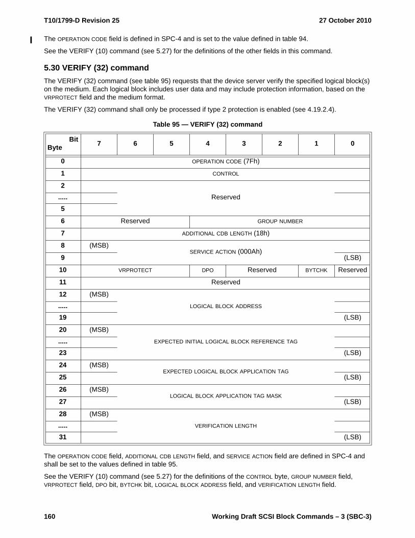
T10/1799-D Revision 25 27 October 2010
160 Working Draft SCSI Block Commands – 3 (SBC-3)
The OPERATION CODE field is defined in SPC-4 and is set to the value defined in table 94.
See the VERIFY (10) command (see 5.27) for the definitions of the other fields in this command.
5.30 VERIFY (32) commandThe VERIFY (32) command (see table 95) requests that the device server verify the specified logical block(s) on the medium. Each logical block includes user data and may include protection information, based on the VRPROTECT field and the medium format.
The VERIFY (32) command shall only be processed if type 2 protection is enabled (see 4.19.2.4).
The OPERATION CODE field, ADDITIONAL CDB LENGTH field, and SERVICE ACTION field are defined in SPC-4 and shall be set to the values defined in table 95.
See the VERIFY (10) command (see 5.27) for the definitions of the CONTROL byte, GROUP NUMBER field, VRPROTECT field, DPO bit, BYTCHK bit, LOGICAL BLOCK ADDRESS field, and VERIFICATION LENGTH field.
Table 95 — VERIFY (32) command
BitByte 7 6 5 4 3 2 1 0
0 OPERATION CODE (7Fh)
1 CONTROL
2Reserved.....
5
6 Reserved GROUP NUMBER
7 ADDITIONAL CDB LENGTH (18h)
8 (MSB)SERVICE ACTION (000Ah)
9 (LSB)
10 VRPROTECT DPO Reserved BYTCHK Reserved
11 Reserved
12 (MSB)
LOGICAL BLOCK ADDRESS.....19 (LSB)
20 (MSB)
EXPECTED INITIAL LOGICAL BLOCK REFERENCE TAG.....23 (LSB)
24 (MSB)EXPECTED LOGICAL BLOCK APPLICATION TAG
25 (LSB)
26 (MSB)LOGICAL BLOCK APPLICATION TAG MASK
27 (LSB)
28 (MSB)
VERIFICATION LENGTH.....31 (LSB)

27 October 2010 T10/1799-D Revision 25
Working Draft SCSI Block Commands – 3 (SBC-3) 161
When checking of the LOGICAL BLOCK REFERENCE TAG field is enabled (see table 89, table 90, table 91, and table 92 in 5.27), the EXPECTED INITIAL LOGICAL BLOCK REFERENCE TAG field contains the value of the LOGICAL BLOCK REFERENCE TAG field expected in the protection information of the first logical block accessed by the command instead of a value based on the LBA (see 4.19.3).
If the ATO bit is set to one in the Control mode page (see SPC-4), and checking of the LOGICAL BLOCK APPLICATION TAG field is enabled (see table 89, table 90, table 91, and table 92 in 5.27), then the LOGICAL BLOCK APPLICATION TAG MASK field contains a value that is a bit mask for enabling the checking of the LOGICAL BLOCK APPLICATION TAG field in every instance of the protection information for each logical block accessed by the command. A LOGICAL BLOCK APPLICATION TAG MASK bit set to one enables the checking of the corresponding bit of the EXPECTED LOGICAL BLOCK APPLICATION TAG field with the corresponding bit of the LOGICAL BLOCK APPLICATION TAG field in every instance of the protection information.
The LOGICAL BLOCK APPLICATION TAG MASK field and the EXPECTED LOGICAL BLOCK APPLICATION TAG field shall be ignored if:
a) the ATO bit is set to zero; orb) the ATO bit is set to one in the Control mode page (see SPC-4) and checking of the LOGICAL BLOCK
APPLICATION TAG field is disabled (see table 89, table 90, table 91, and table 92 in 5.27).
5.31 WRITE (6) commandThe WRITE (6) command (see table 96) requests that the device server transfer the specified logical block(s) from the data-out buffer and write them. Each logical block transferred includes user data but does not include protection information. Each logical block written includes user data and, if the medium is formatted with protection information enabled, protection information.
The OPERATION CODE field is defined in SPC-4 and is set to the value defined in table 96.
The cache control bits are not provided for this command. Direct-access block devices with cache may have values for the cache control bits that may affect the WRITE (6) command, however no default value is defined by this standard. If explicit control is required, then the WRITE (10) command should be used.
See the PRE-FETCH (10) command (see 5.7) for the definition of the LOGICAL BLOCK ADDRESS field.
The TRANSFER LENGTH field specifies the number of contiguous logical blocks of data that shall be transferred from the data-out buffer and written, starting with the logical block specified by the LOGICAL BLOCK ADDRESS field. A TRANSFER LENGTH field set to zero specifies that 256 logical blocks shall be written. Any other value specifies the number of logical blocks that shall be written. If the LBA plus the transfer length exceeds the capacity of the medium, then the device server shall terminate the command with CHECK CONDITION status with the sense key set to ILLEGAL REQUEST and the additional sense code set to LOGICAL BLOCK ADDRESS OUT OF RANGE. The TRANSFER LENGTH field is constrained by the MAXIMUM TRANSFER LENGTH field in the Block Limits VPD page (see 6.5.3).
NOTE 20 - For the WRITE (10) command, WRITE (12) command, WRITE (16) command, and WRITE (32) command, a TRANSFER LENGTH field set to zero specifies that no logical blocks are transferred.
Table 96 — WRITE (6) command
BitByte 7 6 5 4 3 2 1 0
0 OPERATION CODE (0Ah)
1 Reserved (MSB)
2LOGICAL BLOCK ADDRESS
3 (LSB)
4 TRANSFER LENGTH
5 CONTROL
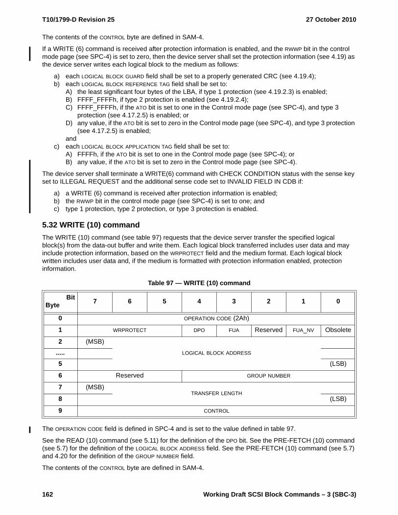
T10/1799-D Revision 25 27 October 2010
162 Working Draft SCSI Block Commands – 3 (SBC-3)
The contents of the CONTROL byte are defined in SAM-4.
If a WRITE (6) command is received after protection information is enabled, and the RWWP bit in the control mode page (see SPC-4) is set to zero, then the device server shall set the protection information (see 4.19) as the device server writes each logical block to the medium as follows:
a) each LOGICAL BLOCK GUARD field shall be set to a properly generated CRC (see 4.19.4);b) each LOGICAL BLOCK REFERENCE TAG field shall be set to:
A) the least significant four bytes of the LBA, if type 1 protection (see 4.19.2.3) is enabled;B) FFFF_FFFFh, if type 2 protection is enabled (see 4.19.2.4);C) FFFF_FFFFh, if the ATO bit is set to one in the Control mode page (see SPC-4), and type 3
protection (see 4.17.2.5) is enabled; orD) any value, if the ATO bit is set to zero in the Control mode page (see SPC-4), and type 3 protection
(see 4.17.2.5) is enabled;and
c) each LOGICAL BLOCK APPLICATION TAG field shall be set to:A) FFFFh, if the ATO bit is set to one in the Control mode page (see SPC-4); orB) any value, if the ATO bit is set to zero in the Control mode page (see SPC-4).
The device server shall terminate a WRITE(6) command with CHECK CONDITION status with the sense key set to ILLEGAL REQUEST and the additional sense code set to INVALID FIELD IN CDB if:
a) a WRITE (6) command is received after protection information is enabled;b) the RWWP bit in the control mode page (see SPC-4) is set to one; andc) type 1 protection, type 2 protection, or type 3 protection is enabled.
5.32 WRITE (10) commandThe WRITE (10) command (see table 97) requests that the device server transfer the specified logical block(s) from the data-out buffer and write them. Each logical block transferred includes user data and may include protection information, based on the WRPROTECT field and the medium format. Each logical block written includes user data and, if the medium is formatted with protection information enabled, protection information.
The OPERATION CODE field is defined in SPC-4 and is set to the value defined in table 97.
See the READ (10) command (see 5.11) for the definition of the DPO bit. See the PRE-FETCH (10) command (see 5.7) for the definition of the LOGICAL BLOCK ADDRESS field. See the PRE-FETCH (10) command (see 5.7) and 4.20 for the definition of the GROUP NUMBER field.
The contents of the CONTROL byte are defined in SAM-4.
Table 97 — WRITE (10) command
BitByte 7 6 5 4 3 2 1 0
0 OPERATION CODE (2Ah)
1 WRPROTECT DPO FUA Reserved FUA_NV Obsolete
2 (MSB)
LOGICAL BLOCK ADDRESS.....5 (LSB)
6 Reserved GROUP NUMBER
7 (MSB)TRANSFER LENGTH
8 (LSB)
9 CONTROL

27 October 2010 T10/1799-D Revision 25
Working Draft SCSI Block Commands – 3 (SBC-3) 163
The device server shall check the protection information, if any, transferred from the data-out buffer based on the WRPROTECT field as described in table 98. All footnotes for table 98 are at the end of the table.
Table 98 — WRPROTECT field (part 1 of 2)
Code
Logical unit formatted
with protection
information
Field in protection
information
Device server check
If check fails d i, additional sense code
000b Yes f g h No protection information received from application client to checkNo No protection information received from application client to check
001b bYes e
LOGICAL BLOCK GUARD
Shall LOGICAL BLOCK GUARD CHECK FAILED
LOGICAL BLOCK APPLICATION TAG
May c LOGICAL BLOCK APPLICATION TAG CHECK FAILED
LOGICAL BLOCK REFERENCE TAG
Shall (except for type 3) j
LOGICAL BLOCK REFERENCE TAG CHECK FAILED
No a No protection information available to check
010b bYes e
LOGICAL BLOCK GUARD
Shall not No check performed
LOGICAL BLOCK APPLICATION TAG
May c LOGICAL BLOCK APPLICATION TAG CHECK FAILED
LOGICAL BLOCK REFERENCE TAG
May j LOGICAL BLOCK REFERENCE TAG CHECK FAILED
No a No protection information available to check
011b bYes e
LOGICAL BLOCK GUARD
Shall not No check performed
LOGICAL BLOCK APPLICATION TAG
Shall not No check performed
LOGICAL BLOCK REFERENCE TAG
Shall not No check performed
No a No protection information available to check
100b bYes e
LOGICAL BLOCK GUARD
Shall LOGICAL BLOCK GUARD CHECK FAILED
LOGICAL BLOCK APPLICATION TAG
Shall not No check performed
LOGICAL BLOCK REFERENCE TAG
Shall not No check performed
No a No protection information available to check
101b bYes e
LOGICAL BLOCK GUARD
Shall LOGICAL BLOCK GUARD CHECK FAILED
LOGICAL BLOCK APPLICATION TAG
May c LOGICAL BLOCK APPLICATION TAG CHECK FAILED
LOGICAL BLOCK REFERENCE TAG
May j LOGICAL BLOCK REFERENCE TAG CHECK FAILED
No a No protection information available to check110b
to 111b
Reserved

T10/1799-D Revision 25 27 October 2010
164 Working Draft SCSI Block Commands – 3 (SBC-3)
a If a logical unit supports protection information (see 4.19) but has not been formatted with protection information, then the device server shall terminate a command specifying a write operation to the logical unit with CHECK CONDITION status with the sense key set to ILLEGAL REQUEST and the additional sense code set to INVALID FIELD IN CDB.
b If the logical unit does not support protection information, then the device server should terminate the requested command with CHECK CONDITION status with the sense key set to ILLEGAL REQUEST and the additional sense code set to INVALID FIELD IN CDB.
c If the device server has knowledge of the contents of the LOGICAL BLOCK APPLICATION TAG field, and the ATO bit is set to one in the Control mode page (see SPC-4), then the device server may check each logical block application tag. If the ATO bit in the Control mode page (see SPC-4) is set to one, then this knowledge is acquired from:a) the EXPECTED LOGICAL BLOCK APPLICATION TAG field and the LOGICAL BLOCK APPLICATION TAG MASK
field in the CDB, if a WRITE (32) command (see 5.35) is received by the device server;b) the Application Tag mode page (see 6.4.3), if a command other than WRITE (32) is received by the
device server and the ATMPE bit in the Control mode page (see SPC-4) is set to one orc) a method not defined by this standard, if a command other than WRITE (32) is received by the
device server, and the ATMPE bit is set to zero.d If the device server terminates the command with CHECK CONDITION status, then the device server
shall set the sense key to ABORTED COMMAND.e The device server shall preserve the contents of protection information (e.g., write it to medium or store
it in non-volatile memory).f The device server shall write a properly generated CRC (see 4.19.4.2) into each LOGICAL BLOCK GUARD
field.g If If the RWWP bit in the Control mode page (see SPC-4) is set to one, then the device server shall
terminate the command with CHECK CONDITION status with the sense key set to ILLEGAL REQUEST and the additional sense code set to INVALID FIELD IN CDB. If the RWWP bit is set to zero, and:a) type 1 protection is enabled, then the device server shall write the least significant four bytes of
each LBA into the LOGICAL BLOCK REFERENCE TAG field of each of the written logical blocks; orb) type 2 protection or type 3 protection is enabled, then the device server shall write a value of
FFFF_FFFFh into the LOGICAL BLOCK REFERENCE TAG field of each of the written logical blocks.h If the ATO bit is set to one in the Control mode page (see SPC-4), then the device server shall write
FFFFh into each LOGICAL BLOCK APPLICATION TAG field. If the ATO bit is set to zero, then the device server may write any value into each LOGICAL BLOCK APPLICATION TAG field.
i If multiple errors occur while the device server is processing the command, then the selection by the device server of which error to report is not defined by this standard.
j If type 1 protection is enabled, then the device server shall check the logical block reference tag by comparing it to the lower four bytes of the LBA associated with the logical block. If type 2 protection is enabled, and the device server has knowledge of the contents of the LOGICAL BLOCK REFERENCE TAG field, then the device server shall check each logical block reference tag. If type 2 protection is enabled, then this knowledge may be acquired through the EXPECTED INITIAL LOGICAL BLOCK REFERENCE TAG field in a WRITE (32) command (see 5.35). If type 3 protection is enabled, the ATO bit is set to one in the Control mode page (see SPC-4), and the device server has knowledge of the contents of the LOGICAL BLOCK REFERENCE TAG field, then the device server may check each logical block reference tag. If type 3 protection is enabled, then the method for acquiring this knowledge is not defined by this standard.
Table 98 — WRPROTECT field (part 2 of 2)
Code
Logical unit formatted
with protection
information
Field in protection
information
Device server check
If check fails d i, additional sense code

27 October 2010 T10/1799-D Revision 25
Working Draft SCSI Block Commands – 3 (SBC-3) 165
The force unit access (FUA) and force unit access non-volatile cache (FUA_NV) bits are defined in table 99.
If logical blocks are transferred directly to a cache, then the device server may complete the command with GOOD status prior to writing the logical blocks to the medium. Any error that occurs after the device server has completed the command with GOOD status is returned as a deferred error, and information regarding the error is not reported until a subsequent command.
The TRANSFER LENGTH field specifies the number of contiguous logical blocks of data that shall be transferred from the data-out buffer and written, starting with the logical block specified by the LOGICAL BLOCK ADDRESS field. A TRANSFER LENGTH field set to zero specifies that no logical blocks shall be written. This condition shall not be considered an error. Any other value specifies the number of logical blocks that shall be written. If the LBA plus the transfer length exceeds the capacity of the medium, then the device server shall terminate the command with CHECK CONDITION status with the sense key set to ILLEGAL REQUEST and the additional sense code set to LOGICAL BLOCK ADDRESS OUT OF RANGE. The TRANSFER LENGTH field is constrained by the MAXIMUM TRANSFER LENGTH field in the Block Limits VPD page (see 6.5.3).
NOTE 21 - For the WRITE (6) command, a TRANSFER LENGTH field set to zero specifies that 256 logical blocks are transferred.
Table 99 — Force unit access for write operations
FUA FUA_NV Description
0 0 The device server shall write the logical blocks to volatile cache, non-volatile cache, and/or the medium.
0 1
If the NV_SUP bit is set to one in the Extended INQUIRY Data VPD page (see SPC-4), then the device server shall write the logical blocks to non-volatile cache and/or the medium.
If the NV_SUP bit is set to zero in the Extended INQUIRY Data VPD page (see SPC-4), then the device server shall write the logical blocks to volatile cache, non-volatile cache, and/or the medium.
1 0 or 1The device server shall write the logical blocks to the medium, and shall not complete the command with GOOD status until the logical blocks have been written on the medium without error.

T10/1799-D Revision 25 27 October 2010
166 Working Draft SCSI Block Commands – 3 (SBC-3)
5.33 WRITE (12) commandThe WRITE (12) command (see table 100) requests that the device server transfer the specified logical block(s) from the data-out buffer and write them. Each logical block transferred includes user data and may include protection information, based on the WRPROTECT field and the medium format. Each logical block written includes user data and, if the medium is formatted with protection information enabled, protection information.
The OPERATION CODE field is defined in SPC-4 and is set to the value defined in table 100.
See the WRITE (10) command (see 5.32) for the definitions of the other fields in this command.
Table 100 — WRITE (12) command
BitByte 7 6 5 4 3 2 1 0
0 OPERATION CODE (AAh)
1 WRPROTECT DPO FUA Reserved FUA_NV Obsolete
2 (MSB)
LOGICAL BLOCK ADDRESS.....5 (LSB)
6 (MSB)
TRANSFER LENGTH.....9 (LSB)
10Restricted
for MMC-6
Reserved GROUP NUMBER
11 CONTROL

27 October 2010 T10/1799-D Revision 25
Working Draft SCSI Block Commands – 3 (SBC-3) 167
5.34 WRITE (16) commandThe WRITE (16) command (see table 101) requests that the device server transfer the specified logical block(s) from the data-out buffer and write them. Each logical block transferred includes user data and may include protection information, based on the WRPROTECT field and the medium format. Each logical block written includes user data and, if the medium is formatted with protection information enabled, protection information.
The OPERATION CODE field is defined in SPC-4 and is set to the value defined in table 101.
See the WRITE (10) command (see 5.32) for the definitions of the other fields in this command.
Table 101 — WRITE (16) command
BitByte 7 6 5 4 3 2 1 0
0 OPERATION CODE (8Ah)
1 WRPROTECT DPO FUA Reserved FUA_NV Reserved
2 (MSB)
LOGICAL BLOCK ADDRESS.....9 (LSB)
10 (MSB)
TRANSFER LENGTH.....13 (LSB)
14Restricted
for MMC-6
Reserved GROUP NUMBER
15 CONTROL

T10/1799-D Revision 25 27 October 2010
168 Working Draft SCSI Block Commands – 3 (SBC-3)
5.35 WRITE (32) commandThe WRITE (32) command (see table 102) requests that the device server transfer the specified logical block(s) from the data-out buffer and write them. Each logical block transferred includes user data and may include protection information, based on the WRPROTECT field and the medium format. Each logical block written includes user data and, if the medium is formatted with protection information enabled, protection information.
The WRITE (32) command shall only be processed if type 2 protection is enabled (see 4.19.2.4).
The OPERATION CODE field, ADDITIONAL CDB LENGTH field, and SERVICE ACTION field are defined in SPC-4 and shall be set to the values defined in table 102.
See the WRITE (10) command (see 5.32) for the definitions of the CONTROL byte, GROUP NUMBER field, the WRPROTECT field, the DPO bit, the FUA bit, the FUA_NV bit, the LOGICAL BLOCK ADDRESS field, and the TRANSFER LENGTH field.
Table 102 — WRITE (32) command
BitByte 7 6 5 4 3 2 1 0
0 OPERATION CODE (7Fh)
1 CONTROL
2Reserved.....
5
6 Reserved GROUP NUMBER
7 ADDITIONAL CDB LENGTH (18h)
8 (MSB)SERVICE ACTION (000Bh)
9 (LSB)
10 WRPROTECT DPO FUA Reserved FUA_NV Reserved
11 Reserved
12 (MSB)
LOGICAL BLOCK ADDRESS.....19 (LSB)
20 (MSB)
EXPECTED INITIAL LOGICAL BLOCK REFERENCE TAG.....23 (LSB)
24 (MSB)EXPECTED LOGICAL BLOCK APPLICATION TAG
25 (LSB)
26 (MSB)LOGICAL BLOCK APPLICATION TAG MASK
27 (LSB)
28 (MSB)
TRANSFER LENGTH.....31 (LSB)

27 October 2010 T10/1799-D Revision 25
Working Draft SCSI Block Commands – 3 (SBC-3) 169
When checking of the LOGICAL BLOCK REFERENCE TAG field is enabled (see table 98 in 5.32), the EXPECTED INITIAL LOGICAL BLOCK REFERENCE TAG field contains the value of the LOGICAL BLOCK REFERENCE TAG field expected in the protection information of the first logical block accessed by the command instead of a value based on the LBA (see 4.19.3).
If the ATO bit is set to one in the Control mode page (see SPC-4) and checking of the LOGICAL BLOCK APPLICATION TAG field is enabled (see table 98 in 5.32), then the LOGICAL BLOCK APPLICATION TAG MASK field contains a value that is a bit mask for enabling the checking of the LOGICAL BLOCK APPLICATION TAG field in every instance of protection information for each logical block accessed by the command. A LOGICAL BLOCK APPLICATION TAG MASK bit set to one enables the checking of the corresponding bit of the EXPECTED LOGICAL BLOCK APPLICATION TAG field with the corresponding bit of the LOGICAL BLOCK APPLICATION TAG field in every instance of protection information.
The LOGICAL BLOCK APPLICATION TAG MASK field and the EXPECTED LOGICAL BLOCK APPLICATION TAG field shall be ignored if:
a) the ATO bit is set to zero; orb) the ATO bit is set to one in the Control mode page (see SPC-4) and checking of the LOGICAL BLOCK
APPLICATION TAG field is disabled (see table 98 in 5.32).
5.36 WRITE AND VERIFY (10) commandThe WRITE AND VERIFY (10) command (see table 103) requests that the device server transfer the specified logical block(s) from the data-out buffer, write them to the medium, and then verify that they are correctly written. Each logical block includes user data and may include protection information, based on the WRPROTECT field and the medium format. The logical blocks are only transferred once from the data-out buffer to the device server.
If the Verify Error Recovery mode page (see 6.4.8) is also implemented, then the current settings in that mode page along with the AWRE bit in the Read-Write Error Recovery mode page (see 6.4.7) specify the verification error criteria. If these mode pages are not implemented, then the verification criteria is vendor specific.
The OPERATION CODE field is defined in SPC-4 and is set to the value defined in table 103.
See the PRE-FETCH (10) command (see 5.7) for the definition of the LOGICAL BLOCK ADDRESS field. See the PRE-FETCH (10) command (see 5.7) and 4.20 for the definition of the GROUP NUMBER field. See the WRITE (10) command (see 5.32) for the definitions of the CONTROL byte, TRANSFER LENGTH field and the WRPROTECT field. See the READ (10) command (see 5.11) for the definition of the DPO bit.
A byte check (BYTCHK) bit set to zero specifies that, after writing, the device server perform a medium verification with no data comparison. A BYTCHK bit set to one specifies that, after writing, the device server perform a byte-by-byte comparison of data written on the medium with the data just written. If the comparison
Table 103 — WRITE AND VERIFY (10) command
BitByte 7 6 5 4 3 2 1 0
0 OPERATION CODE (2Eh)
1 WRPROTECT DPO Reserved BYTCHK Obsolete
2 (MSB)
LOGICAL BLOCK ADDRESS.....5 (LSB)
6 Reserved GROUP NUMBER
7 (MSB)TRANSFER LENGTH
8 (LSB)
9 CONTROL
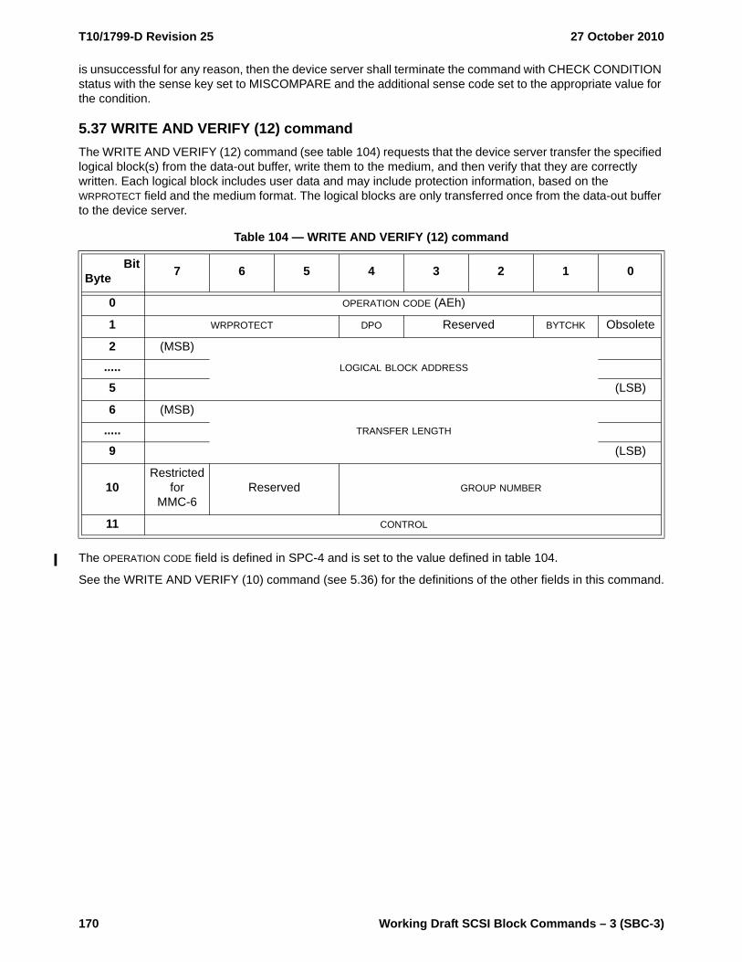
T10/1799-D Revision 25 27 October 2010
170 Working Draft SCSI Block Commands – 3 (SBC-3)
is unsuccessful for any reason, then the device server shall terminate the command with CHECK CONDITION status with the sense key set to MISCOMPARE and the additional sense code set to the appropriate value for the condition.
5.37 WRITE AND VERIFY (12) commandThe WRITE AND VERIFY (12) command (see table 104) requests that the device server transfer the specified logical block(s) from the data-out buffer, write them to the medium, and then verify that they are correctly written. Each logical block includes user data and may include protection information, based on the WRPROTECT field and the medium format. The logical blocks are only transferred once from the data-out buffer to the device server.
The OPERATION CODE field is defined in SPC-4 and is set to the value defined in table 104.
See the WRITE AND VERIFY (10) command (see 5.36) for the definitions of the other fields in this command.
Table 104 — WRITE AND VERIFY (12) command
BitByte 7 6 5 4 3 2 1 0
0 OPERATION CODE (AEh)
1 WRPROTECT DPO Reserved BYTCHK Obsolete
2 (MSB)
LOGICAL BLOCK ADDRESS.....5 (LSB)
6 (MSB)
TRANSFER LENGTH.....9 (LSB)
10Restricted
for MMC-6
Reserved GROUP NUMBER
11 CONTROL

27 October 2010 T10/1799-D Revision 25
Working Draft SCSI Block Commands – 3 (SBC-3) 171
5.38 WRITE AND VERIFY (16) commandThe WRITE AND VERIFY (16) command (see table 105) requests that the device server transfer the specified logical block(s) from the data-out buffer, write them to the medium, and then verify that they are correctly written. Each logical block includes user data and may include protection information, based on the WRPROTECT field and the medium format. The logical blocks are only transferred once from the data-out buffer to the device server.
The OPERATION CODE field is defined in SPC-4 and is set to the value defined in table 105.
See the WRITE AND VERIFY (10) command (see 5.36) for the definitions of the other fields in this command.
Table 105 — WRITE AND VERIFY (16) command
BitByte 7 6 5 4 3 2 1 0
0 OPERATION CODE (8Eh)
1 WRPROTECT DPO Reserved BYTCHK Reserved
2 (MSB)
LOGICAL BLOCK ADDRESS.....9 (LSB)
10 (MSB)
TRANSFER LENGTH.....13 (LSB)
14Restricted
for MMC-6
Reserved GROUP NUMBER
15 CONTROL

T10/1799-D Revision 25 27 October 2010
172 Working Draft SCSI Block Commands – 3 (SBC-3)
5.39 WRITE AND VERIFY (32) commandThe WRITE AND VERIFY (32) command (see table 106) requests that the device server transfer the specified logical block(s) from the data-out buffer, write them to the medium, and then verify that they are correctly written. Each logical block includes user data and may include protection information, based on the WRPROTECT field and the medium format. The logical blocks are only transferred once from the data-out buffer to the device server.
The OPERATION CODE field, ADDITIONAL CDB LENGTH field, and SERVICE ACTION field are defined in SPC-4 and shall be set to the values defined in table 106.
See the WRITE AND VERIFY (10) command (see 5.36) for the definitions of the CONTROL byte, GROUP NUMBER field, the WRPROTECT field, the DPO bit, the BYTCHK bit, the LOGICAL BLOCK ADDRESS field, and the TRANSFER LENGTH field.
Table 106 — WRITE AND VERIFY (32) command
BitByte 7 6 5 4 3 2 1 0
0 OPERATION CODE (7Fh)
1 CONTROL
2Reserved.....
5
6 Reserved GROUP NUMBER
7 ADDITIONAL CDB LENGTH (18h)
8 (MSB)SERVICE ACTION (000Ch)
9 (LSB)
10 WRPROTECT DPO Reserved BYTCHK Reserved
11 Reserved
12 (MSB)
LOGICAL BLOCK ADDRESS.....19 (LSB)
20 (MSB)
EXPECTED INITIAL LOGICAL BLOCK REFERENCE TAG.....23 (LSB)
24 (MSB)EXPECTED LOGICAL BLOCK APPLICATION TAG
25 (LSB)
26 (MSB)LOGICAL BLOCK APPLICATION TAG MASK
27 (LSB)
28 (MSB)
TRANSFER LENGTH.....31 (LSB)

27 October 2010 T10/1799-D Revision 25
Working Draft SCSI Block Commands – 3 (SBC-3) 173
When checking of the LOGICAL BLOCK REFERENCE TAG field is enabled (see table 98 in 5.32), the EXPECTED INITIAL LOGICAL BLOCK REFERENCE TAG field contains the value of the LOGICAL BLOCK REFERENCE TAG field expected in the protection information of the first logical block accessed by the command instead of a value based on the LBA (see 4.19.3).
If the ATO bit is set to one in the Control mode page (see SPC-4) and checking of the LOGICAL BLOCK APPLICATION TAG field is enabled (see table 98 in 5.32), then the LOGICAL BLOCK APPLICATION TAG MASK field contains a value that is a bit mask for enabling the checking of the LOGICAL BLOCK APPLICATION TAG field in every instance of protection information for each logical block accessed by the command. A LOGICAL BLOCK APPLICATION TAG MASK bit set to one enables the checking of the corresponding bit of the EXPECTED LOGICAL BLOCK APPLICATION TAG field with the corresponding bit of the LOGICAL BLOCK APPLICATION TAG field in every instance of protection information.
If the ATO bit is set to one in the Control mode page (see SPC-4) and checking of the LOGICAL BLOCK APPLICATION TAG field is disabled (see table 98 in 5.32), or if the ATO bit is set to zero, then the LOGICAL BLOCK APPLICATION TAG MASK field and the EXPECTED LOGICAL BLOCK APPLICATION TAG field shall be ignored.
5.40 WRITE LONG (10) commandThe WRITE LONG (10) command (see table 107) requests that the device server mark a logical block or physical block as containing an error, or transfer data for a single logical block or physical block from the data-out buffer and write it to the medium. The data written shall be the same length and shall be in the same order as the data returned by the READ LONG (10) command (see 5.19). The device server shall write the logical block or physical block to the medium, and shall not complete the command with GOOD status until the logical block has been written on the medium without error.
The OPERATION CODE field is defined in SPC-4 and is set to the value defined in table 107.
Table 107 — WRITE LONG (10) command
BitByte 7 6 5 4 3 2 1 0
0 OPERATION CODE (3Fh)
1 COR_DIS WR_UNCOR PBLOCK Reserved Obsolete
2 (MSB)
LOGICAL BLOCK ADDRESS.....5 (LSB)
6 Reserved
7 (MSB)BYTE TRANSFER LENGTH
8 (LSB)
9 CONTROL

T10/1799-D Revision 25 27 October 2010
174 Working Draft SCSI Block Commands – 3 (SBC-3)
The correction disabled (COR_DIS) bit, the write uncorrectable error (WR_UNCOR) bit, and the physical block (PBLOCK) bit are defined in table 108. If there is more than one logical block per physical block (i.e., the LOGICAL BLOCKS PER PHYSICAL BLOCK EXPONENT field in the READ CAPACITY (16) data (see 5.16.1) is set to a non-zero value), then the device server shall support the WR_UNCOR bit and the PBLOCK bit.
Table 108 — COR_DIS bit, WR_UNCOR bit, and PBLOCK bit (part 1 of 2)
COR_DIS WR_UNCOR PBLOCK
More than one logical block per physical block a
Description
0 0
0 yes or no Write only the specified logical block using the value in the BYTE TRANSFER LENGTH field.
1
no
Terminate the WRITE LONG command with CHECK CONDITION status with the sense key set to ILLEGAL REQUEST and the additional sense code set to INVALID FIELD IN CDB.
yesWrite the entire physical block containing the specified logical block using the value in the BYTE TRANSFER LENGTH field.
0 1
0 yes or no
Mark only the specified logical block as containing a pseudo unrecovered error with correction enabled (see 4.16.2) in a manner that causes the device server to perform the maximum error recovery as defined by the Read-Write Error Recovery mode page (see 6.4.7).
Ignore the BYTE TRANSFER LENGTH field, and transfer no data.
1
no
Terminate the WRITE LONG command with CHECK CONDITION status with the sense key set to ILLEGAL REQUEST and the additional sense code set to INVALID FIELD IN CDB.
yes
Mark the entire physical block containing the specified logical block as containing a pseudo unrecovered error with correction enabled (i.e., mark all of the logical blocks in the same physical block that contains the specified logical block as containing a pseudo unrecovered error with correction enabled) (see 4.16.2).
Ignore the BYTE TRANSFER LENGTH field, and transfer no data.
a An entry of “yes” means that the LOGICAL BLOCKS PER PHYSICAL BLOCK EXPONENT field in the READ CAPACITY (16) data (see 5.16.1) is set to a non-zero value. An entry of “no” means that the field is set to zero.

27 October 2010 T10/1799-D Revision 25
Working Draft SCSI Block Commands – 3 (SBC-3) 175
1 0
0 yes or no
Mark only the specified logical block as containing a pseudo unrecovered error with correction disabled (see 4.16.2)
Write only the specified logical block using the value in the BYTE TRANSFER LENGTH field.
1
no
Terminate the WRITE LONG command with CHECK CONDITION status with the sense key set to ILLEGAL REQUEST and the additional sense code set to INVALID FIELD IN CDB.
yes
Mark the entire physical block containing the specified logical block as containing a pseudo unrecovered error with correction disabled (i.e., mark all of the logical blocks in the same physical block that contains the specified logical block as containing a pseudo unrecovered error with correction disabled) (see 4.16.2).
Write the entire physical block containing the specified logical block using the value in the BYTE TRANSFER LENGTH field.
1 1
0 yes or no
Mark only the specified logical block as containing a pseudo unrecovered error with correction disabled (see 4.16.2).
Ignore the BYTE TRANSFER LENGTH field, and transfer no data.
1
no
Terminate the WRITE LONG command with CHECK CONDITION status with the sense key set to ILLEGAL REQUEST and the additional sense code set to INVALID FIELD IN CDB.
yes
Mark the entire physical block containing the specified logical block as containing a pseudo unrecovered error with correction disabled (i.e., mark all of the logical blocks in the same physical block that contains the specified logical block as containing a pseudo unrecovered error with correction disabled) (see 4.16.2).
Ignore the BYTE TRANSFER LENGTH field, and transfer no data.
Table 108 — COR_DIS bit, WR_UNCOR bit, and PBLOCK bit (part 2 of 2)
COR_DIS WR_UNCOR PBLOCK
More than one logical block per physical block a
Description
a An entry of “yes” means that the LOGICAL BLOCKS PER PHYSICAL BLOCK EXPONENT field in the READ CAPACITY (16) data (see 5.16.1) is set to a non-zero value. An entry of “no” means that the field is set to zero.

T10/1799-D Revision 25 27 October 2010
176 Working Draft SCSI Block Commands – 3 (SBC-3)
Any pseudo unrecovered error with correction disabled shall remain in effect until the logical block is unmapped or written by any means (e.g., another WRITE LONG command with the COR_DIS bit set to zero and the WR_UNCOR bit set to zero that writes to the same logical block, any WRITE command that specifies a write to the same logical block, or a FORMAT UNIT command). An unmap operation on a logical block with a pseudo unrecovered error with correction disabled may or may not preserve the pseudo unrecovered error.
In the Extended INQUIRY Data VPD page (see SPC-4), the setting of the CD_SUP bit indicates whether or not the logical unit supports the CD_DIS bit being set to one, and the setting of the WU_SUP bit indicates whether or not the logical unit supports the WR_UNCOR bit being set to one.
The LOGICAL BLOCK ADDRESS field specifies an LBA. If the specified LBA exceeds the capacity of the medium, then the device server shall terminate the command with CHECK CONDITION status with the sense key set to ILLEGAL REQUEST and the additional sense code set to LOGICAL BLOCK ADDRESS OUT OF RANGE.
If table 108 defines that the value in the BYTE TRANSFER LENGTH field is used, then the BYTE TRANSFER LENGTH field specifies the number of bytes of data that the device server shall transfer from the data-out buffer and write to the specified logical block or physical block. If the BYTE TRANSFER LENGTH field is not set to zero and does not match the data length that the device server returns for a READ LONG command, then the device server shall terminate the command with CHECK CONDITION status with the sense key set to ILLEGAL REQUEST and the additional sense code set to INVALID FIELD IN CDB. In the sense data (see 4.16 and SPC-4), the ILI and VALID bits shall be set to one and the INFORMATION field shall be set to the difference (i.e., residue) of the requested length minus the actual length in bytes. Negative values shall be indicated by two's complement notation. If the BYTE TRANSFER LENGTH field is set to zero, then no bytes shall be written. This condition shall not be considered an error.
The contents of the CONTROL byte are defined in SAM-4.
5.41 WRITE LONG (16) commandThe WRITE LONG (16) command (see table 109) requests that the device server mark a logical block or physical block as containing an error, or transfer data for a single logical block or physical block from the data-out buffer and write it to the medium. The data written shall be the same length and shall be in the same order as the data returned by the READ LONG (16) command (see 5.20). The device server shall write the logical block or physical block to the medium, and shall not complete the command with GOOD status until the logical block has been written on the medium without error. This command is implemented as a service action of the SERVICE ACTION OUT operation code (see A.2).
Table 109 — WRITE LONG (16) command
BitByte 7 6 5 4 3 2 1 0
0 OPERATION CODE (9Fh)
1 COR_DIS WR_UNCOR PBLOCK SERVICE ACTION (11h)
2 (MSB)
LOGICAL BLOCK ADDRESS.....9 (LSB)
10Reserved
11
12 (MSB)BYTE TRANSFER LENGTH
13 (LSB)
14 Reserved
15 CONTROL

27 October 2010 T10/1799-D Revision 25
Working Draft SCSI Block Commands – 3 (SBC-3) 177
The OPERATION CODE field and SERVICE ACTION field are defined in SPC-4 and shall be set to the values defined in table 109.
See the WRITE LONG (10) command (see 5.40) for the definitions of the fields in this command.
5.42 WRITE SAME (10) commandThe WRITE SAME (10) command (see table 110) requests that the device server transfer a single logical block from the data-out buffer and write the contents of that logical block, with modifications based on the LBDATA bit and the PBDATA bit, to the specified range of LBAs. Each logical block includes user data and may include protection information, based on the WRPROTECT field and the medium format.
The OPERATION CODE field is defined in SPC-4 and is set to the value defined in table 110.
See the WRITE (10) command (see 5.32) for the definitions of the CONTROL byte and WRPROTECT field. See the PRE-FETCH (10) command (see 5.7) for the definition of the LOGICAL BLOCK ADDRESS field. See the PRE-FETCH (10) command (see 5.7) and 4.20 for the definition of the GROUP NUMBER field.
Table 110 — WRITE SAME (10) command
BitByte 7 6 5 4 3 2 1 0
0 OPERATION CODE (41h)
1 WRPROTECT Reserved PBDATA LBDATA Obsolete
2 (MSB)
LOGICAL BLOCK ADDRESS.....5 (LSB)
6 Reserved GROUP NUMBER
7 (MSB)NUMBER OF LOGICAL BLOCKS
8 (LSB)
9 CONTROL

T10/1799-D Revision 25 27 October 2010
178 Working Draft SCSI Block Commands – 3 (SBC-3)
Table 111 describes the LBDATA bit and the PBDATA bit.
The NUMBER OF LOGICAL BLOCKS field specifies the number of contiguous logical blocks to be written, starting with the logical block specified by the LOGICAL BLOCK ADDRESS field. A NUMBER OF LOGICAL BLOCKS field set to zero specifies that the device server write all the logical blocks starting with the one specified in the LOGICAL BLOCK ADDRESS field to the last logical block on the medium. If the LBA plus the number of logical blocks exceeds the capacity of the medium, then the device server shall terminate the command with CHECK
Table 111 — LBDATA bit and PBDATA bit
LBDATA PBDATA Description
0 0
The device server shall write the single block of user data received from the data-out buffer to each logical block without modification.
If the medium is formatted with type 1 or type 2 protection information, then:a) The device server shall place the value from each LOGICAL BLOCK
REFERENCE TAG field received in the single block of data from the data-out buffer into the corresponding LOGICAL BLOCK REFERENCE TAG field of the first logical block written to the medium. The device sever shall place the value of the previous LOGICAL BLOCK REFERENCE TAG field plus one into each of the subsequent LOGICAL BLOCK REFERENCE TAG fields;
b) If the ATO bit is set to one in the Control mode page (see SPC-4), then the device server shall place each logical block application tag received in the single block of data into the corresponding LOGICAL BLOCK APPLICATION TAG field of each logical block. If the ATO bit is set to zero, then the device server may write any value into the LOGICAL BLOCK APPLICATION TAG field(s) of each logical block; and
c) The device server shall place the value from each LOGICAL BLOCK GUARD field received in the single block of data from the data-out buffer into the corresponding LOGICAL BLOCK GUARD field of each logical block.
If the medium is formatted with type 3 protection information:a) If the ATO bit is set to one in the Control mode page (see SPC-4), then the
device server shall place each logical block application tag received in the single block of data into the corresponding LOGICAL BLOCK REFERENCE TAG field of each logical block. If the ATO bit is set to zero, then the device server may write any value into the LOGICAL BLOCK REFERENCE TAG field(s) of each logical block; and
b) The device server shall place the value from each LOGICAL BLOCK GUARD field received in the single block of data from the data-out buffer into the corresponding LOGICAL BLOCK GUARD field of each logical block.
0 1 aThe device server shall replace the first eight bytes of the block received from the data-out buffer for each physical sector with the physical address of the sector being written using the physical sector format (see 5.3.2.4.5).
1 a 0
The device server shall replace the first four bytes of the block received from the data-out buffer with the least significant four bytes of the LBA of the block being written, ending with the least significant byte (e.g., if the LBA is 7766_5544_3322_1100h, 3322_1100h, then 33h is written first, and 00h is written last).
1 1The device server shall terminate the command with CHECK CONDITION status with the sense key set to ILLEGAL REQUEST and the additional sense code set to INVALID FIELD IN CDB.
a If the medium is formatted with protection information, then all of the protection information shall be written to a default value of FFFF_FFFF_FFFF_FFFFh in each of the written logical blocks.

27 October 2010 T10/1799-D Revision 25
Working Draft SCSI Block Commands – 3 (SBC-3) 179
CONDITION status with the sense key set to ILLEGAL REQUEST and the additional sense code set to LOGICAL BLOCK ADDRESS OUT OF RANGE.
5.43 WRITE SAME (16) commandThe WRITE SAME (16) command (see table 112) requests that the device server transfer a single logical block from the data-out buffer and write the contents of that logical block, with modifications based on the LBDATA bit and the PBDATA bit, to the specified range of LBAs. Each logical block includes user data and may include protection information, based on the WRPROTECT field and the medium format.
The OPERATION CODE field is defined in SPC-4 and is set to the value defined in table 112.
See the WRITE SAME (10) command (see 5.42) for the definitions of the other fields in this command except for the ANCHOR bit and the UNMAP bit.
Table 112 — WRITE SAME (16) command
BitByte 7 6 5 4 3 2 1 0
0 OPERATION CODE (93h)
1 WRPROTECT ANCHOR UNMAP PBDATA LBDATA Reserved
2 (MSB)
LOGICAL BLOCK ADDRESS.....9 (LSB)
10 (MSB)
NUMBER OF LOGICAL BLOCKS.....13 (LSB)
14 Reserved GROUP NUMBER
15 CONTROL

T10/1799-D Revision 25 27 October 2010
180 Working Draft SCSI Block Commands – 3 (SBC-3)
If the logical unit supports logical block provisioning management (see 4.7.3), then the ANCHOR bit, the UNMAP bit, and the ANC_SUP bit in the Logical Block Provisioning VPD page (see 6.5.4) determine how the device server processes the command as described in table 113.
The device server shall ignore the UNMAP bit and the ANCHOR bit, or the device server shall terminate the command with CHECK CONDITION status with the sense key set to ILLEGAL REQUEST and the additional sense code set to INVALID FIELD IN CDB if:
a) the logical unit is fully provisioned (i.e., the LBPME bit is set to zero in the READ CAPACITY (16) parameter data (see 5.16.2)); and
b) the UNMAP bit is set to one or the ANCHOR bit is set to one.
Table 113 — ANCHOR bit, UNMAP bit, and ANC_SUP bit relationships
UNMAP bit a ANCHOR bit ANC_SUP bit b Action
0b0b n/a Write c
1b n/a Error d
1b
0b n/a Unmap e
1b0 Error d
1 Anchor f
a The device server in a logical unit that supports logical block provisioning management (see 4.7.3) may implement the UNMAP bit.
b See the Logical Block Provisioning VPD page (see 6.5.4).c The device server shall perform the specified write operation on each LBA specified by the command.d The device server shall terminate the command with CHECK CONDITION status with the sense key set
to ILLEGAL REQUEST and the additional sense code set to INVALID FIELD IN CDB.e The device server in a thin provisioned logical unit should deallocate each LBA specified by the
command (see 4.7.4.3.1) but may anchor each LBA specified by the command (see 4.7.4.4.1). The device server in a resource provisioned logical unit should anchor each LBA specified by the command. If the device server does not deallocate or anchor the LBA, then the device server shall perform the specified write operation (see 4.7.3.4.2).
f The device server should anchor each LBA specified by the command (see 4.7.4.4.1). If the device server does not anchor the LBA, then the device server shall perform the specified write operation (see 4.7.3.4.2).

27 October 2010 T10/1799-D Revision 25
Working Draft SCSI Block Commands – 3 (SBC-3) 181
5.44 WRITE SAME (32) commandThe WRITE SAME (32) command (see table 114) requests that the device server transfer a single logical block from the data-out buffer and write the contents of that logical block, with modifications based on the LBDATA bit and the PBDATA bit, to the specified range of LBAs. Each logical block includes user data and may include protection information, based on the WRPROTECT field and the medium format.
The OPERATION CODE field, ADDITIONAL CDB LENGTH field, and SERVICE ACTION field are defined in SPC-4 and shall be set to the values defined in table 114.
See the WRITE SAME (10) command (see 5.42) for the definitions of the CONTROL byte, GROUP NUMBER field, the WRPROTECT field, the PBDATA bit, the LBDATA bit, the LOGICAL BLOCK ADDRESS field, and the NUMBER OF LOGICAL BLOCKS field.
See the WRITE SAME (16) command (see 5.43) for the definitions of the UNMAP bit and the ANCHOR bit.
Table 114 — WRITE SAME (32) command
BitByte 7 6 5 4 3 2 1 0
0 OPERATION CODE (7Fh)
1 CONTROL
2Reserved.....
5
6 Reserved GROUP NUMBER
7 ADDITIONAL CDB LENGTH (18h)
8 (MSB)SERVICE ACTION (000Dh)
9 (LSB)
10 WRPROTECT ANCHOR UNMAP PBDATA LBDATA Reserved
11 Reserved
12 (MSB)
LOGICAL BLOCK ADDRESS.....19 (LSB)
20 (MSB)
EXPECTED INITIAL LOGICAL BLOCK REFERENCE TAG.....23 (LSB)
24 (MSB)EXPECTED LOGICAL BLOCK APPLICATION TAG
25 (LSB)
26 (MSB)LOGICAL BLOCK APPLICATION TAG MASK
27 (LSB)
28 (MSB)
NUMBER OF LOGICAL BLOCKS.....31 (LSB)
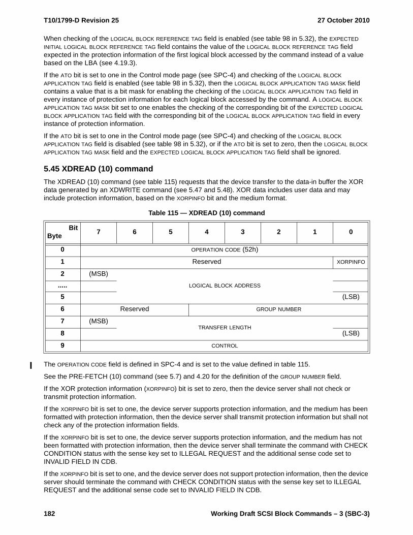
T10/1799-D Revision 25 27 October 2010
182 Working Draft SCSI Block Commands – 3 (SBC-3)
When checking of the LOGICAL BLOCK REFERENCE TAG field is enabled (see table 98 in 5.32), the EXPECTED INITIAL LOGICAL BLOCK REFERENCE TAG field contains the value of the LOGICAL BLOCK REFERENCE TAG field expected in the protection information of the first logical block accessed by the command instead of a value based on the LBA (see 4.19.3).
If the ATO bit is set to one in the Control mode page (see SPC-4) and checking of the LOGICAL BLOCK APPLICATION TAG field is enabled (see table 98 in 5.32), then the LOGICAL BLOCK APPLICATION TAG MASK field contains a value that is a bit mask for enabling the checking of the LOGICAL BLOCK APPLICATION TAG field in every instance of protection information for each logical block accessed by the command. A LOGICAL BLOCK APPLICATION TAG MASK bit set to one enables the checking of the corresponding bit of the EXPECTED LOGICAL BLOCK APPLICATION TAG field with the corresponding bit of the LOGICAL BLOCK APPLICATION TAG field in every instance of protection information.
If the ATO bit is set to one in the Control mode page (see SPC-4) and checking of the LOGICAL BLOCK APPLICATION TAG field is disabled (see table 98 in 5.32), or if the ATO bit is set to zero, then the LOGICAL BLOCK APPLICATION TAG MASK field and the EXPECTED LOGICAL BLOCK APPLICATION TAG field shall be ignored.
5.45 XDREAD (10) commandThe XDREAD (10) command (see table 115) requests that the device transfer to the data-in buffer the XOR data generated by an XDWRITE command (see 5.47 and 5.48). XOR data includes user data and may include protection information, based on the XORPINFO bit and the medium format.
The OPERATION CODE field is defined in SPC-4 and is set to the value defined in table 115.
See the PRE-FETCH (10) command (see 5.7) and 4.20 for the definition of the GROUP NUMBER field.
If the XOR protection information (XORPINFO) bit is set to zero, then the device server shall not check or transmit protection information.
If the XORPINFO bit is set to one, the device server supports protection information, and the medium has been formatted with protection information, then the device server shall transmit protection information but shall not check any of the protection information fields.
If the XORPINFO bit is set to one, the device server supports protection information, and the medium has not been formatted with protection information, then the device server shall terminate the command with CHECK CONDITION status with the sense key set to ILLEGAL REQUEST and the additional sense code set to INVALID FIELD IN CDB.
If the XORPINFO bit is set to one, and the device server does not support protection information, then the device server should terminate the command with CHECK CONDITION status with the sense key set to ILLEGAL REQUEST and the additional sense code set to INVALID FIELD IN CDB.
Table 115 — XDREAD (10) command
BitByte 7 6 5 4 3 2 1 0
0 OPERATION CODE (52h)
1 Reserved XORPINFO
2 (MSB)
LOGICAL BLOCK ADDRESS.....5 (LSB)
6 Reserved GROUP NUMBER
7 (MSB)TRANSFER LENGTH
8 (LSB)
9 CONTROL

27 October 2010 T10/1799-D Revision 25
Working Draft SCSI Block Commands – 3 (SBC-3) 183
The XOR data transferred is identified by the LOGICAL BLOCK ADDRESS field and the TRANSFER LENGTH field. The LOGICAL BLOCK ADDRESS field and TRANSFER LENGTH field shall be the same as, or a subset of, those specified in a prior XDWRITE command. If a match is not found, then the device server shall terminate the command with CHECK CONDITION status with the sense key set to ILLEGAL REQUEST and the additional sense code set to INVALID FIELD IN CDB. The TRANSFER LENGTH field is constrained by the MAXIMUM TRANSFER LENGTH field in the Block Limits VPD page (see 6.5.3).
The contents of the CONTROL byte are defined in SAM-4.
5.46 XDREAD (32) commandThe XDREAD (32) command (see table 116) requests that the device transfer to the data-in buffer the XOR data generated by an XDWRITE command (see 5.47 and 5.48). XOR data includes user data and may include protection information, based on the XORPINFO bit and the medium format.
The OPERATION CODE field, ADDITIONAL CDB LENGTH field, and SERVICE ACTION field are defined in SPC-4 and shall be set to the value defined in table 116.
See the XDREAD (10) command (see 5.45) and SPC-4 for the definitions of the other fields in this command.
Table 116 — XDREAD (32) command
BitByte 7 6 5 4 3 2 1 0
0 OPERATION CODE (7Fh)
1 CONTROL
2Reserved.....
5
6 Reserved GROUP NUMBER
7 ADDITIONAL CDB LENGTH (18h)
8 (MSB)SERVICE ACTION (0003h)
9 (LSB)
10 Reserved XORPINFO
11 Reserved
12 (MSB)
LOGICAL BLOCK ADDRESS.....19 (LSB)
20Reserved.....
27
28 (MSB)
TRANSFER LENGTH.....31 (LSB)
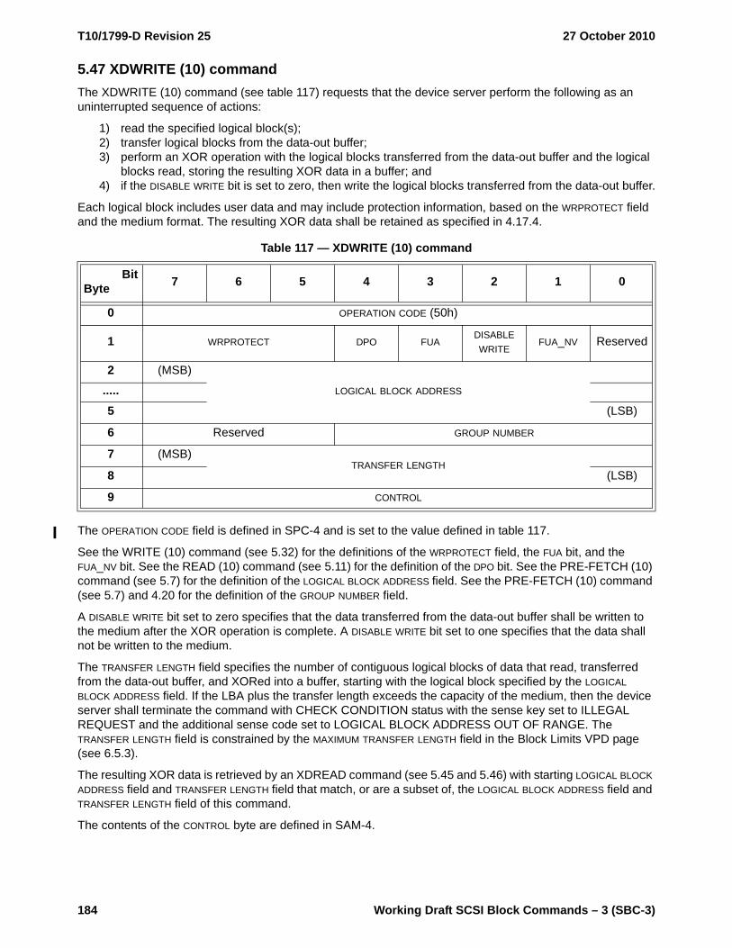
T10/1799-D Revision 25 27 October 2010
184 Working Draft SCSI Block Commands – 3 (SBC-3)
5.47 XDWRITE (10) commandThe XDWRITE (10) command (see table 117) requests that the device server perform the following as an uninterrupted sequence of actions:
1) read the specified logical block(s);2) transfer logical blocks from the data-out buffer;3) perform an XOR operation with the logical blocks transferred from the data-out buffer and the logical
blocks read, storing the resulting XOR data in a buffer; and4) if the DISABLE WRITE bit is set to zero, then write the logical blocks transferred from the data-out buffer.
Each logical block includes user data and may include protection information, based on the WRPROTECT field and the medium format. The resulting XOR data shall be retained as specified in 4.17.4.
The OPERATION CODE field is defined in SPC-4 and is set to the value defined in table 117.
See the WRITE (10) command (see 5.32) for the definitions of the WRPROTECT field, the FUA bit, and the FUA_NV bit. See the READ (10) command (see 5.11) for the definition of the DPO bit. See the PRE-FETCH (10) command (see 5.7) for the definition of the LOGICAL BLOCK ADDRESS field. See the PRE-FETCH (10) command (see 5.7) and 4.20 for the definition of the GROUP NUMBER field.
A DISABLE WRITE bit set to zero specifies that the data transferred from the data-out buffer shall be written to the medium after the XOR operation is complete. A DISABLE WRITE bit set to one specifies that the data shall not be written to the medium.
The TRANSFER LENGTH field specifies the number of contiguous logical blocks of data that read, transferred from the data-out buffer, and XORed into a buffer, starting with the logical block specified by the LOGICAL BLOCK ADDRESS field. If the LBA plus the transfer length exceeds the capacity of the medium, then the device server shall terminate the command with CHECK CONDITION status with the sense key set to ILLEGAL REQUEST and the additional sense code set to LOGICAL BLOCK ADDRESS OUT OF RANGE. The TRANSFER LENGTH field is constrained by the MAXIMUM TRANSFER LENGTH field in the Block Limits VPD page (see 6.5.3).
The resulting XOR data is retrieved by an XDREAD command (see 5.45 and 5.46) with starting LOGICAL BLOCK ADDRESS field and TRANSFER LENGTH field that match, or are a subset of, the LOGICAL BLOCK ADDRESS field and TRANSFER LENGTH field of this command.
The contents of the CONTROL byte are defined in SAM-4.
Table 117 — XDWRITE (10) command
BitByte 7 6 5 4 3 2 1 0
0 OPERATION CODE (50h)
1 WRPROTECT DPO FUADISABLE WRITE
FUA_NV Reserved
2 (MSB)
LOGICAL BLOCK ADDRESS.....5 (LSB)
6 Reserved GROUP NUMBER
7 (MSB)TRANSFER LENGTH
8 (LSB)
9 CONTROL

27 October 2010 T10/1799-D Revision 25
Working Draft SCSI Block Commands – 3 (SBC-3) 185
5.48 XDWRITE (32) commandThe XDWRITE (32) command (see table 118) requests that the device server perform the following as an uninterrupted sequence of actions:
1) read the specified logical block(s);2) transfer logical blocks from the data-out buffer;3) perform an XOR operation with the logical blocks transferred from the data-out buffer and the logical
blocks read, storing the resulting XOR data in a buffer; and4) if the DISABLE WRITE bit is set to zero, then write the logical blocks transferred from the data-out buffer.
Each logical block includes user data and may include protection information, based on the WRPROTECT field and the medium format. The resulting XOR data shall be retained as specified in 4.17.4.
The OPERATION CODE field, ADDITIONAL CDB LENGTH field, and SERVICE ACTION field are defined in SPC-4 and shall be set to the values defined in table 118.
See the XDWRITE (10) command (see 5.47) and SPC-4 for the definitions of the other fields in this command.
Table 118 — XDWRITE (32) command
BitByte 7 6 5 4 3 2 1 0
0 OPERATION CODE (7Fh)
1 CONTROL
2Reserved.....
5
6 Reserved GROUP NUMBER
7 ADDITIONAL CDB LENGTH (18h)
8 (MSB)SERVICE ACTION (0004h)
9 (LSB)
10 WRPROTECT DPO FUADISABLE WRITE
FUA_NV Reserved
11 Reserved
12 (MSB)
LOGICAL BLOCK ADDRESS.....19 (LSB)
20Reserved.....
27
28 (MSB)
TRANSFER LENGTH.....31 (LSB)

T10/1799-D Revision 25 27 October 2010
186 Working Draft SCSI Block Commands – 3 (SBC-3)
5.49 XDWRITEREAD (10) commandThe XDWRITEREAD (10) command (see table 119) requests that the device server perform the following as an uninterrupted sequence of actions:
1) read the specified logical block(s);2) transfer logical blocks from the data-out buffer;3) XOR the logical blocks transferred from the data-out buffer with the logical blocks read, storing the
resulting XOR data in a buffer;4) if the DISABLE WRITE bit is set to zero, then write the logical blocks transferred from the data-out buffer;
and5) transfer the resulting XOR data to the data-in buffer.
Each logical block includes user data and may include protection information, based on the WRPROTECT field, the XORPINFO bit, and the medium format. This command is equivalent to an XDWRITE (10) command (see 5.47) followed by an XDREAD (10) command (see 5.45) specifying the same values for the GROUP NUMBER field, the LOGICAL BLOCK ADDRESS field, and the TRANSFER LENGTH field. This command is only available on transport protocols supporting bidirectional commands.
The OPERATION CODE field is defined in SPC-4 and is set to the value defined in table 119.
See the XDWRITE (10) command (see 5.47) and XDREAD (10) command (see 5.45) for the definitions of the other fields in this command.
Table 119 — XDWRITEREAD (10) command
BitByte 7 6 5 4 3 2 1 0
0 OPERATION CODE (53h)
1 WRPROTECT DPO FUADISABLE WRITE
FUA_NV XORPINFO
2 (MSB)
LOGICAL BLOCK ADDRESS.....5 (LSB)
6 Reserved GROUP NUMBER
7 (MSB)TRANSFER LENGTH
8 (LSB)
9 CONTROL

27 October 2010 T10/1799-D Revision 25
Working Draft SCSI Block Commands – 3 (SBC-3) 187
5.50 XDWRITEREAD (32) commandThe XDWRITEREAD (32) command (see table 120) requests that the device server perform the following as an uninterrupted sequence of actions:
1) read the specified logical block(s);2) transfer logical blocks from the data-out buffer;3) XOR the logical blocks transferred from the data-out buffer with the logical blocks read, storing the
resulting XOR data in a buffer;4) if the DISABLE WRITE bit is set to zero, then write the logical blocks transferred from the data-out buffer;
and5) transfer the resulting XOR data to the data-in buffer.
Each logical block includes user data and may include protection information, based on the WRPROTECT field, the XORPINFO bit, and the medium format. This command is equivalent to an XDWRITE (32) command (see 5.48) followed by an XDREAD (32) command (see 5.46) specifying the same values for the GROUP NUMBER field, the LOGICAL BLOCK ADDRESS field, and the TRANSFER LENGTH field. This command is only available on transport protocols supporting bidirectional commands.
The OPERATION CODE field, ADDITIONAL CDB LENGTH field, and SERVICE ACTION field are defined in SPC-4 and shall be set to the values defined in table 120.
See the XDWRITEREAD (10) command (see 5.49) and SPC-4 for the definitions of the fields in this command.
Table 120 — XDWRITEREAD (32) command
BitByte 7 6 5 4 3 2 1 0
0 OPERATION CODE (7Fh)
1 CONTROL
2Reserved.....
5
6 Reserved GROUP NUMBER
7 ADDITIONAL CDB LENGTH (18h)
8 (MSB)SERVICE ACTION (0007h)
9 (LSB)
10 WRPROTECT DPO FUADISABLE WRITE
FUA_NV XORPINFO
11 Reserved
12 (MSB)LOGICAL BLOCK ADDRESS.....
19 (LSB)
20Reserved.....
27
28 (MSB)TRANSFER LENGTH.....
31 (LSB)

T10/1799-D Revision 25 27 October 2010
188 Working Draft SCSI Block Commands – 3 (SBC-3)
5.51 XPWRITE (10) commandThe XPWRITE (10) command (see table 121) requests that the device server perform the following as an uninterrupted sequence of actions:
1) read the specified logical block(s);2) transfer logical blocks from the data-out buffer; and3) XOR the logical blocks transferred from the data-out buffer with the logical blocks read, writing the
resulting XOR data.
Each logical block includes user data and may include protection information, based on the XORPINFO bit and the medium format.
The OPERATION CODE field is defined in SPC-4 and is set to the value defined in table 121.
See the READ (10) command (see 5.11) for the definition of the DPO bit. See the WRITE (10) command (see 5.32) for the definitions of the FUA bit and the FUA_NV bit. See the PRE-FETCH (10) command (see 5.7) for the definition of the LOGICAL BLOCK ADDRESS field. See the PRE-FETCH (10) command (see 5.7) and 4.20 for the definition of the GROUP NUMBER field.
If the XOR protection information (XORPINFO) bit is set to zero, the device server supports protection information, and the medium has been formatted with protection information, then the device server shall terminate the command with CHECK CONDITION status with the sense key set to ILLEGAL REQUEST and the additional sense code set to INVALID FIELD IN CDB.
If the XORPINFO bit is set to one, the device server supports protection information, and the medium has been formatted with protection information, then the device server shall XOR the user data and protection information transferred from the data-out buffer with the user data and protection information read, and then write the resulting XOR data. The device server shall not check any of the protection information fields.
If the XORPINFO bit is set to one, the device server supports protection information, and the medium has not been formatted with protection information, then the device server shall terminate the command with CHECK CONDITION status with the sense key set to ILLEGAL REQUEST and the additional sense code set to INVALID FIELD IN CDB.
If the XORPINFO bit is set to one, and the device server does not support protection information, then the device server should terminate the command with CHECK CONDITION status with the sense key set to ILLEGAL REQUEST and the additional sense code set to INVALID FIELD IN CDB.
The TRANSFER LENGTH field specifies the number of contiguous logical blocks that shall be read, XORed with logical blocks transferred from the data-out buffer, and written, starting with the logical block specified by the LOGICAL BLOCK ADDRESS field. If the LBA plus the transfer length exceeds the capacity of the medium, then the device server shall terminate the command with CHECK CONDITION status with the sense key set to
Table 121 — XPWRITE (10) command
BitByte 7 6 5 4 3 2 1 0
0 OPERATION CODE (51h)
1 Reserved DPO FUA Reserved FUA_NV XORPINFO
2 (MSB)LOGICAL BLOCK ADDRESS.....
5 (LSB)
6 Reserved GROUP NUMBER
7 (MSB)TRANSFER LENGTH
8 (LSB)
9 CONTROL

27 October 2010 T10/1799-D Revision 25
Working Draft SCSI Block Commands – 3 (SBC-3) 189
ILLEGAL REQUEST and the additional sense code set to LOGICAL BLOCK ADDRESS OUT OF RANGE. The TRANSFER LENGTH field is constrained by the MAXIMUM TRANSFER LENGTH field in the Block Limits VPD page (see 6.5.3).
The contents of the CONTROL byte are defined in SAM-4.
5.52 XPWRITE (32) commandThe XPWRITE (32) command (see table 122) requests that the device server perform the following as an uninterrupted sequence of actions:
1) read the specified logical block(s);2) transfer logical blocks from the data-out buffer; and3) XOR the logical blocks transferred from the data-out buffer with the logical blocks read, writing the
resulting XOR data.
Each logical block includes user data and may include protection information, based on the XORPINFO bit and the medium format.
The OPERATION CODE field, ADDITIONAL CDB LENGTH field, and SERVICE ACTION field are defined in SPC-4 and shall be set to the values defined in table 122.
See the XPWRITE (10) command (see 5.51) and SPC-4 for the definitions of the fields in this command.
Table 122 — XPWRITE (32) command
BitByte 7 6 5 4 3 2 1 0
0 OPERATION CODE (7Fh)
1 CONTROL
2Reserved.....
5
6 Reserved GROUP NUMBER
7 ADDITIONAL CDB LENGTH (18h)
8 (MSB)SERVICE ACTION (0006h)
9 (LSB)
10 Reserved DPO FUA Reserved FUA_NV XORPINFO
11 Reserved
12 (MSB)LOGICAL BLOCK ADDRESS.....
19 (LSB)
20Reserved.....
27
28 (MSB)TRANSFER LENGTH.....
31 (LSB)

T10/1799-D Revision 25 27 October 2010
190 Working Draft SCSI Block Commands – 3 (SBC-3)
6 Parameters for direct-access block devices
6.1 Parameters for direct-access block devices overviewParameters for direct-access block devices are defined in clause 6 as follows:
a) Diagnostic parameters are defined in 6.2;b) Log parameters are defined in 6.3;c) Mode parameters are defined in 6.4; andd) Vital product data (VPD) parameters are defined in 6.5.
6.2 Diagnostic parameters
6.2.1 Diagnostic parameters overview
This subclause defines the pages and descriptors for diagnostic parameters used by direct-access block devices.
The diagnostic pages and their corresponding page codes for direct-access block devices are defined in table 123.
Table 123 — Diagnostic page codes for direct-access block devices
Diagnostic page name Page code Reference
Diagnostic pages assigned by SPC-4 30h to 3Fh SPC-4
SCSI enclosure services diagnostic pages 01h to 2Fh SES-2
Supported diagnostic pages 00h SPC-4
Translate Address Input diagnostic page40h
6.2.2
Translate Address Output diagnostic page 6.2.3
Obsolete 41h
Vendor specific diagnostic pages 80h to FFh
Reserved for this standard 42h to 7Fh
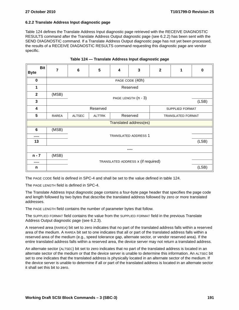
27 October 2010 T10/1799-D Revision 25
Working Draft SCSI Block Commands – 3 (SBC-3) 191
6.2.2 Translate Address Input diagnostic page
Table 124 defines the Translate Address Input diagnostic page retrieved with the RECEIVE DIAGNOSTIC RESULTS command after the Translate Address Output diagnostic page (see 6.2.2) has been sent with the SEND DIAGNOSTIC command. If a Translate Address Output diagnostic page has not yet been processed, the results of a RECEIVE DIAGNOSTIC RESULTS command requesting this diagnostic page are vendor specific.
The PAGE CODE field is defined in SPC-4 and shall be set to the value defined in table 124.
The PAGE LENGTH field is defined in SPC-4.
The Translate Address Input diagnostic page contains a four-byte page header that specifies the page code and length followed by two bytes that describe the translated address followed by zero or more translated addresses.
The PAGE LENGTH field contains the number of parameter bytes that follow.
The SUPPLIED FORMAT field contains the value from the SUPPLIED FORMAT field in the previous Translate Address Output diagnostic page (see 6.2.3).
A reserved area (RAREA) bit set to zero indicates that no part of the translated address falls within a reserved area of the medium. A RAREA bit set to one indicates that all or part of the translated address falls within a reserved area of the medium (e.g., speed tolerance gap, alternate sector, or vendor reserved area). If the entire translated address falls within a reserved area, the device server may not return a translated address.
An alternate sector (ALTSEC) bit set to zero indicates that no part of the translated address is located in an alternate sector of the medium or that the device server is unable to determine this information. An ALTSEC bit set to one indicates that the translated address is physically located in an alternate sector of the medium. If the device server is unable to determine if all or part of the translated address is located in an alternate sector it shall set this bit to zero.
Table 124 — Translate Address Input diagnostic page
BitByte 7 6 5 4 3 2 1 0
0 PAGE CODE (40h)
1 Reserved
2 (MSB)PAGE LENGTH (n - 3)
3 (LSB)
4 Reserved SUPPLIED FORMAT
5 RAREA ALTSEC ALTTRK Reserved TRANSLATED FORMAT
Translated address(es)
6 (MSB)TRANSLATED ADDRESS 1.....
13 (LSB)
.....
n - 7 (MSB)TRANSLATED ADDRESS x (if required).....
n (LSB)

T10/1799-D Revision 25 27 October 2010
192 Working Draft SCSI Block Commands – 3 (SBC-3)
An alternate track (ALTTRK) bit set to zero indicates that no part of the translated address is located on an alternate track of the medium. An ALTTRK bit set to one indicates that part or all of the translated address is located on an alternate track of the medium or the device server is unable to determine if all or part of the translated address is located on an alternate track.
The TRANSLATED FORMAT field contains the value from the TRANSLATE FORMAT field in the previous Translate Address Output diagnostic page (see 6.2.2).
The TRANSLATED ADDRESS field(s) contains the address(es) the device server translated from the address supplied by the application client in the previous Translate Address Output diagnostic page. Each field shall be in the format specified in the TRANSLATE FORMAT field. The formats are described in 5.3.2.4. If the short block format address descriptor is specified, the first four bytes of the TRANSLATED ADDRESS field shall contain the short block format address descriptor and the last four bytes shall contain 0000_0000h.
If the returned data is in short block format, long block format, or physical sector format and the ADDRESS TO TRANSLATE field in the previous Translate Address Output diagnostic page covers more than one address after it has been translated (e.g., because of multiple physical sectors within a single logical block or multiple logical blocks within a single physical sector) the device server shall return all possible addresses that are contained in the area specified by the address to be translated. If the returned data is in bytes from index format, the device server shall return a pair of translated values for each of the possible addresses that are contained in the area specified by the ADDRESS TO TRANSLATE field in the previous Translate Address Output diagnostic page. Of the pair of translated values returned, the first indicates the starting location and the second the ending location of the area.
6.2.3 Translate Address Output diagnostic page
The Translate Address diagnostic pages allow the application client to translate an address in one of the formats supported by the FORMAT UNIT command (see 5.3.2.4) (i.e., a short block format address, a long block format address, a physical sector format address, or a bytes from index format address) into any one of the other formats. The address to be translated is sent to the device server with the SEND DIAGNOSTIC command and the results are returned to the application client by the RECEIVE DIAGNOSTIC RESULTS command.
Table 125 defines the format of the Translate Address Output diagnostic page sent with the SEND DIAGNOSTIC command. The translated address is returned in the Translate Address Input diagnostic page (see 6.2.2).
The PAGE CODE field and PAGE LENGTH field are defined in SPC-4 and shall be set to the values defined in table 125.
Table 125 — Translate Address Output diagnostic page
BitByte 7 6 5 4 3 2 1 0
0 PAGE CODE (40h)
1 Reserved
2 (MSB)PAGE LENGTH (000Ah)
3 (LSB)
4 Reserved SUPPLIED FORMAT
5 Reserved TRANSLATE FORMAT
6 (MSB)ADDRESS TO TRANSLATE.....
13 (LSB)

27 October 2010 T10/1799-D Revision 25
Working Draft SCSI Block Commands – 3 (SBC-3) 193
The SUPPLIED FORMAT field specifies the format of the ADDRESS TO TRANSLATE field. Valid values for this field are defined in the DEFECT LIST FORMAT field of the FORMAT UNIT command (see 5.2). If the device server does not support the requested format it shall terminate the SEND DIAGNOSTIC command with CHECK CONDITION status with the sense key set to ILLEGAL REQUEST and the additional sense code set to INVALID FIELD IN PARAMETER LIST.
The TRANSLATE FORMAT field specifies the format the device server shall use for the result of the address translation. Valid values for this field are defined in the DEFECT LIST FORMAT field of the FORMAT UNIT command. If the device server does not support the specified format it shall terminate the SEND DIAGNOSTIC command with CHECK CONDITION status with the sense key set to ILLEGAL REQUEST and the additional sense code set to INVALID FIELD IN PARAMETER LIST.
The ADDRESS TO TRANSLATE field contains a single address descriptor which the application client is requesting the device server to translate. The format of this field depends on the value in the SUPPLIED FORMAT field. The formats are described in 5.3.2.4. If the short block format address descriptor is specified, the first four bytes of the ADDRESS TO TRANSLATE field shall contain the short block format address descriptor and the last four bytes shall contain 0000_0000h.

T10/1799-D Revision 25 27 October 2010
194 Working Draft SCSI Block Commands – 3 (SBC-3)
6.3 Log parameters
6.3.1 Log parameters overview
This subclause defines the pages and descriptors for log parameters used by direct-access block devices. See SPC-4 for a detailed description of logging operations.
The log pages and their corresponding page codes and subpage codes for direct-access block devices are defined in table 126.
Table 126 — Log page codes and subpage codes for direct-access block devices
Log page name Page code a Subpage code a Reference
Application Client log page 0Fh 00h SPC-4
Background Scan Results log page 15h 00h 6.3.2
Buffer Over-Run/Under-Run log page 01h 00h SPC-4
Format Status log page 08h 00h 6.3.3
Informational Exceptions log page 2Fh 00h SPC-4
Last n Deferred Errors Or Asynchronous Events log page 0Bh 00h SPC-4
Last n Error Events log page 07h 00h SPC-4
Logical Block Provisioning log page 0Ch 00h 6.3.4
Non-Medium Error log page 06h 00h SPC-4
Non-volatile Cache log page 17h 00h 6.3.5
Protocol-Specific Port log pages 18h 00h to FEh SPC-4
Read Error Counter log page 03h 00h SPC-4
Self-Test Results log page 10h 00h SPC-4
Solid State Media log page 11h 00h 6.3.6
Start-Stop Cycle Counter log page 0Eh 00h SPC-4
Supported Log Pages and Subpages 00h FFh SPC-4
Supported Log Pages log page 00h 00h SPC-4
Supported Subpages 01h to 3Fh FFh SPC-4
Temperature log page 0Dh 00h SPC-4
Verify Error Counter log page 05h 00h SPC-4
Write Error Counter log page 02h 00h SPC-4
Restricted 09h 00h SPC-4
Restricted 0Ah 00h SPC-4
Vendor specific 30h to 3Eh 00h to FEh n/aa All page code and subpage code combinations not shown in this table are reserved for direct-access
block devices.
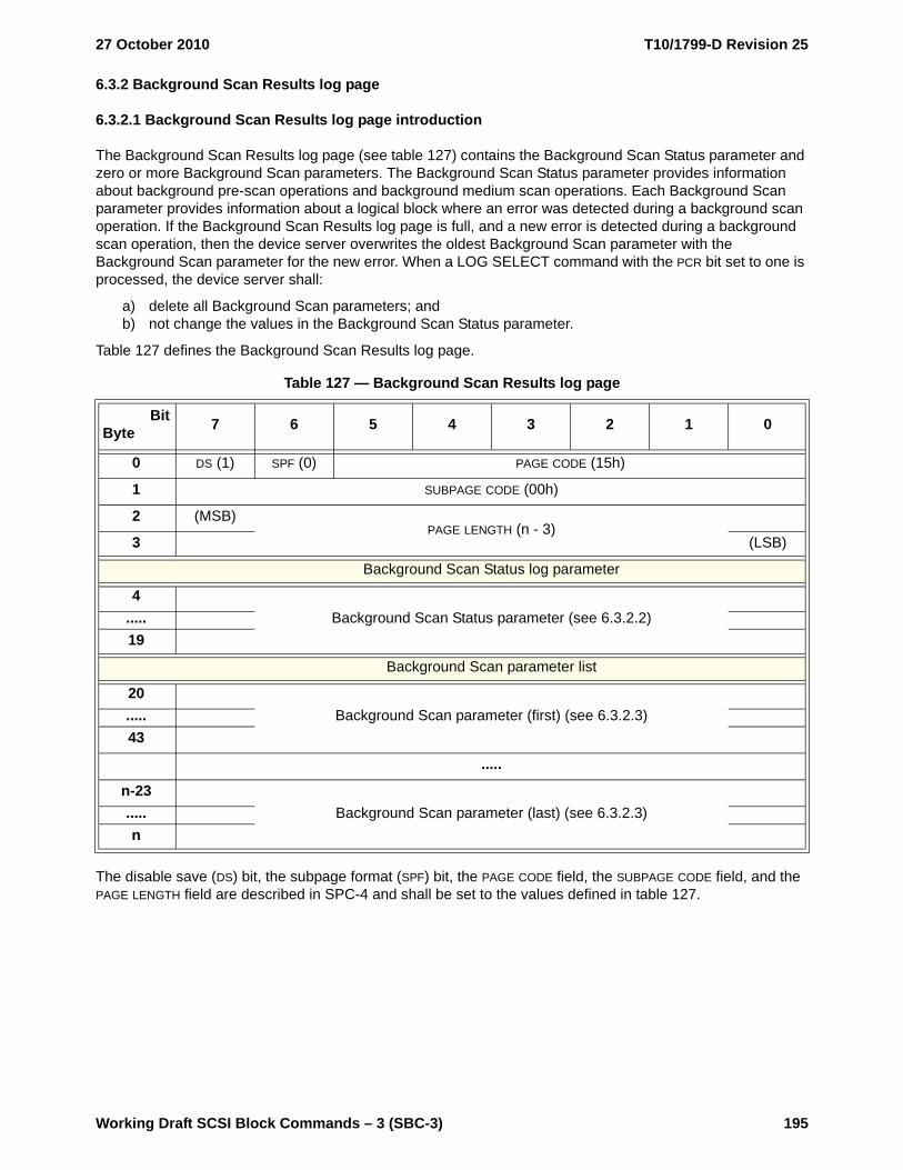
27 October 2010 T10/1799-D Revision 25
Working Draft SCSI Block Commands – 3 (SBC-3) 195
6.3.2 Background Scan Results log page
6.3.2.1 Background Scan Results log page introduction
The Background Scan Results log page (see table 127) contains the Background Scan Status parameter and zero or more Background Scan parameters. The Background Scan Status parameter provides information about background pre-scan operations and background medium scan operations. Each Background Scan parameter provides information about a logical block where an error was detected during a background scan operation. If the Background Scan Results log page is full, and a new error is detected during a background scan operation, then the device server overwrites the oldest Background Scan parameter with the Background Scan parameter for the new error. When a LOG SELECT command with the PCR bit set to one is processed, the device server shall:
a) delete all Background Scan parameters; andb) not change the values in the Background Scan Status parameter.
Table 127 defines the Background Scan Results log page.
The disable save (DS) bit, the subpage format (SPF) bit, the PAGE CODE field, the SUBPAGE CODE field, and the PAGE LENGTH field are described in SPC-4 and shall be set to the values defined in table 127.
Table 127 — Background Scan Results log page
BitByte 7 6 5 4 3 2 1 0
0 DS (1) SPF (0) PAGE CODE (15h)
1 SUBPAGE CODE (00h)
2 (MSB)PAGE LENGTH (n - 3)
3 (LSB)
Background Scan Status log parameter
4Background Scan Status parameter (see 6.3.2.2).....
19
Background Scan parameter list
20Background Scan parameter (first) (see 6.3.2.3).....
43
.....
n-23Background Scan parameter (last) (see 6.3.2.3).....
n
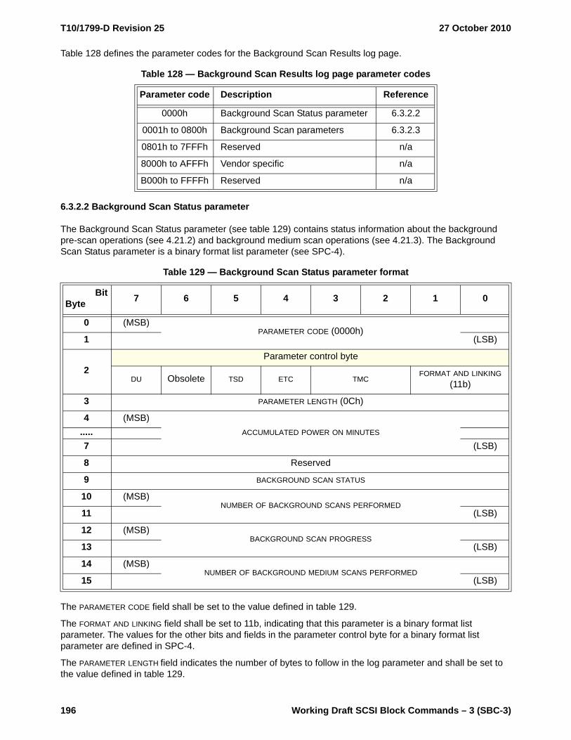
T10/1799-D Revision 25 27 October 2010
196 Working Draft SCSI Block Commands – 3 (SBC-3)
Table 128 defines the parameter codes for the Background Scan Results log page.
6.3.2.2 Background Scan Status parameter
The Background Scan Status parameter (see table 129) contains status information about the background pre-scan operations (see 4.21.2) and background medium scan operations (see 4.21.3). The Background Scan Status parameter is a binary format list parameter (see SPC-4).
The PARAMETER CODE field shall be set to the value defined in table 129.
The FORMAT AND LINKING field shall be set to 11b, indicating that this parameter is a binary format list parameter. The values for the other bits and fields in the parameter control byte for a binary format list parameter are defined in SPC-4.
The PARAMETER LENGTH field indicates the number of bytes to follow in the log parameter and shall be set to the value defined in table 129.
Table 128 — Background Scan Results log page parameter codes
Parameter code Description Reference
0000h Background Scan Status parameter 6.3.2.2
0001h to 0800h Background Scan parameters 6.3.2.3
0801h to 7FFFh Reserved n/a
8000h to AFFFh Vendor specific n/a
B000h to FFFFh Reserved n/a
Table 129 — Background Scan Status parameter format
BitByte 7 6 5 4 3 2 1 0
0 (MSB)PARAMETER CODE (0000h)
1 (LSB)
2Parameter control byte
DU Obsolete TSD ETC TMCFORMAT AND LINKING
(11b)
3 PARAMETER LENGTH (0Ch)
4 (MSB)ACCUMULATED POWER ON MINUTES.....
7 (LSB)
8 Reserved
9 BACKGROUND SCAN STATUS
10 (MSB)NUMBER OF BACKGROUND SCANS PERFORMED
11 (LSB)
12 (MSB)BACKGROUND SCAN PROGRESS
13 (LSB)
14 (MSB)NUMBER OF BACKGROUND MEDIUM SCANS PERFORMED
15 (LSB)

27 October 2010 T10/1799-D Revision 25
Working Draft SCSI Block Commands – 3 (SBC-3) 197
The ACCUMULATED POWER ON MINUTES field indicates the number of minutes the device server has been powered on since manufacturing.
Table 130 defines the BACKGROUND SCANNING STATUS field.
The NUMBER OF BACKGROUND SCANS PERFORMED field indicates the number of background scan operations (i.e., the total number of background pre-scan operations plus the number of background medium scan operations) that have been performed since the SCSI target device was shipped by the manufacturer.
The BACKGROUND SCAN PROGRESS field indicates the percent complete of a background scan operation in progress. The returned value is a numerator that has 65 536 (i.e., 1_0000h) as its denominator. If there is no background scan operation in progress (i.e., no background scan operation has been initiated since power on or the most recent background scan operation has completed), then the device server shall set the BACKGROUND SCAN PROGRESS field to 0000h.
The NUMBER OF BACKGROUND MEDIUM SCANS PERFORMED field indicates the number of background medium scan operations that have been performed since the SCSI target device was shipped by the manufacturer. If the NUMBER OF BACKGROUND MEDIUM SCANS PERFORMED field contains 0000h, then the number of background medium scan operations is not reported.
The total number of background pre-scan operations that have been performed is the value in the NUMBER OF BACKGROUND SCANS PERFORMED field minus the value in the NUMBER OF BACKGROUND MEDIUM SCANS PERFORMED field.
Table 130 — BACKGROUND SCAN STATUS field
Code Description
00h No background scan operation is active.
01h A background medium scan operation is active.
02h A background pre-scan operation is active.
03h A background scan operation was halted due to a fatal error.
04h A background scan operation was halted due to a vendor specific pattern of errors.
05h A background scan operation was halted due to the medium being formatted without the P-list.
06h A background scan operation was halted due to a vendor specific cause.
07h A background scan operation was halted due to the temperature being out of the allowed range.
08h
Background medium scan operations are enabled (i.e., the EN_BMS bit is set to one in the Background Control mode page (see 6.3.3)), and no background medium scan operation is active (i.e., the device server is waiting for Background Medium Scan Interval timer expiration before starting the next background medium scan operation).
09h to FFh Reserved

T10/1799-D Revision 25 27 October 2010
198 Working Draft SCSI Block Commands – 3 (SBC-3)
6.3.2.3 Background Scan parameters
A Background Scan parameter (see table 131) describes a defect location on the medium that was encountered during a background scan operation (see 4.21). The Background Scan parameters are binary format list parameters (see SPC-4).
The PARAMETER CODE field shall be set to a value from 0001h through 0800h. When all of the defined parameter code values have been used, and a new error is discovered during a background scan operation, the oldest Background Scan parameter in the list (i.e., the parameter with the smallest value in the ACCUMULATED POWER ON MINUTES field) shall be discarded, and the PARAMETER CODE field in the Background Scan parameter for the new defect shall be set to the parameter code value of the discarded Background Scan parameter.
The FORMAT AND LINKING field shall be set to 11b, indicating that this parameter is a binary format list parameter. The values for the other bits and fields in the parameter control byte for a binary format list parameter are defined in SPC-4.
The PARAMETER LENGTH field indicates the number of bytes to follow in the log parameter shall be set to the value defined in table 131.
The ACCUMULATED POWER ON MINUTES field indicates the number of minutes the device server has been powered on since manufacturing at the time the background scan error occurred.
Table 131 — Background Scan parameter format
BitByte 7 6 5 4 3 2 1 0
0 (MSB)PARAMETER CODE (0001h to 0800h)
1 (LSB)
2Parameter control byte
DU Obsolete TSD ETC TMCFORMAT AND LINKING
(11b)
3 PARAMETER LENGTH (14h)
4 (MSB)ACCUMULATED POWER ON MINUTES.....
7 (LSB)
8 REASSIGN STATUS SENSE KEY
9 ADDITIONAL SENSE CODE
10 ADDITIONAL SENSE CODE QUALIFIER
11Vendor specific.....
15
16 (MSB)LOGICAL BLOCK ADDRESS.....
23 (LSB)

27 October 2010 T10/1799-D Revision 25
Working Draft SCSI Block Commands – 3 (SBC-3) 199
Table 132 defines the REASSIGN STATUS field.
Table 132 — REASSIGN STATUS field (part 1 of 2)
Code Error logging a Description
0h Reserved
1h Yes
An error was detected while reading the logical block specified by the LOGICAL BLOCK ADDRESS field during a background scan operation, and reassignment of the logical block is pending receipt of: b c
a) a command performing a write operation, if automatic write reassignment is allowed (i.e., the AWRE bit is set to one in the Read-Write Error Recovery mode page (see 6.4.8); or
b) a REASSIGN BLOCKS command (see 5.21).
2h NoAn error was detected while reading the logical block specified by the LOGICAL BLOCK ADDRESS field during a background scan operation and the logical block was reassigned by the device server with recovered data.
3h Reserved
4h Yes
An error was detected:a) while reading the logical block specified by the LOGICAL BLOCK ADDRESS field
during a background scan operation;b) reassignment of the logical block by the device server failed; andc) the logical block may or may not have an uncorrectable error.
5h NoAn error was detected while reading the logical block specified by the LOGICAL BLOCK ADDRESS field during a background scan operation and the error was corrected by the device server rewriting the logical block without reassignment.
6h Yes
An error was detected while reading the logical block specified by the LOGICAL BLOCK ADDRESS field during a background scan operation, and the logical block:
a) was reassigned by the application client: andb) contains valid data (e.g., as the result of reassignment by a REASSIGN
BLOCKS command during which the data was recovered, or by a command performing a write operation). c
a If the LOWIR bit in the Background Control mode page (see 6.4.3) is set to one, then “No” indicates that a Background Medium Scan parameter entry shall not be generated for the error, and “Yes” indicates that a Background Medium Scan parameter entry shall be generated for the error. If the LOWIR bit is set to zero, then a Background Medium Scan parameter entry shall be generated for all errors.
b If an application client knows the correct data for the logical block, then the application client should use a command performing a write operation to reassign the logical block using the correct data (e.g., in a redundancy group (see 4.17.1), the application client writes data to the logical block regenerated from the data on the other logical units in the redundancy group). If an application client uses a REASSIGN BLOCKS command to reassign the logical block, then the device server may not be able to recover the data and does not report whether or not the data was recovered.
c The REASSIGN STATUS field in a given log parameter changes from 1h or 4h to 6h, 7h, or 8h when the logical block is reassigned, rewritten, or failed reassignment (i.e., the data in the reassigned block is not valid). If the logical block is reassigned or rewritten, any subsequent medium error occurring for the logical block is reported in a new log parameter with the same value in the LOGICAL BLOCK ADDRESS field as the value in the LOGICAL BLOCK ADDRESS field in the log parameter for the previous medium error for the logical block.

T10/1799-D Revision 25 27 October 2010
200 Working Draft SCSI Block Commands – 3 (SBC-3)
If sense data is available, then the device server shall set the SENSE KEY field, ADDITIONAL SENSE CODE field, and the ADDITIONAL SENSE CODE QUALIFIER field to a hierarchy of additional information relating to error conditions that occurred during the background scan operation. The content of these fields is represented in the same format used by the sense data (see SPC-4).
The LOGICAL BLOCK ADDRESS field indicates the LBA associated with the medium error.
7h Yes
An error was detected while reading the logical block specified by the LOGICAL BLOCK ADDRESS field during a background scan operation, and the logical block:
a) was reassigned by the application client; andb) does not contain valid data (e.g., as a result of reassignment by a REASSIGN
BLOCKS command during which the data was not recovered). c
8h Yes
An error was detected while reading the logical block specified by the LOGICAL BLOCK ADDRESS field during a background scan operation and the logical block was not successfully reassigned by the application client (e.g., by a REASSIGN BLOCKS command that failed)
9h to Fh Reserved
Table 132 — REASSIGN STATUS field (part 2 of 2)
Code Error logging a Description
a If the LOWIR bit in the Background Control mode page (see 6.4.3) is set to one, then “No” indicates that a Background Medium Scan parameter entry shall not be generated for the error, and “Yes” indicates that a Background Medium Scan parameter entry shall be generated for the error. If the LOWIR bit is set to zero, then a Background Medium Scan parameter entry shall be generated for all errors.
b If an application client knows the correct data for the logical block, then the application client should use a command performing a write operation to reassign the logical block using the correct data (e.g., in a redundancy group (see 4.17.1), the application client writes data to the logical block regenerated from the data on the other logical units in the redundancy group). If an application client uses a REASSIGN BLOCKS command to reassign the logical block, then the device server may not be able to recover the data and does not report whether or not the data was recovered.
c The REASSIGN STATUS field in a given log parameter changes from 1h or 4h to 6h, 7h, or 8h when the logical block is reassigned, rewritten, or failed reassignment (i.e., the data in the reassigned block is not valid). If the logical block is reassigned or rewritten, any subsequent medium error occurring for the logical block is reported in a new log parameter with the same value in the LOGICAL BLOCK ADDRESS field as the value in the LOGICAL BLOCK ADDRESS field in the log parameter for the previous medium error for the logical block.

27 October 2010 T10/1799-D Revision 25
Working Draft SCSI Block Commands – 3 (SBC-3) 201
6.3.3 Format Status log page
The Format Status log page (log page code 08h) captures the state of the direct-access block device since the most recent successful FORMAT UNIT command (see 5.2) was completed. This log page also provides Defect Management information for the device server.
The Format Status log page uses the log page format defined in SPC-4.
Table 133 defines the parameter codes for the Format Status log page.
The PARAMETER LENGTH field of each log parameter (see SPC-4) contains the length of the corresponding PARAMETER VALUE field and is vendor specific.
Event counts are returned as a result of the LOG SENSE command. The default value for each event count listed table 133 shall be zero. Attempts to change these event counts by issuing a LOG SELECT with these fields set to non-zero values is not considered an error and shall have no effect on the saved values.
If information about a log parameter is not available, the device server shall return a value with each byte set to FFh (e.g., if the PARAMETER LENGTH field is set to 02h, the PARAMETER VALUE field is set to FFFFh). If the most recent FORMAT UNIT command failed, the device server shall return a value with each byte set to FFh for each log parameter.
The Format Data Out parameter contains the entire FORMAT UNIT parameter list (see 5.3.2) from the most recent successful FORMAT UNIT command. This includes:
a) the parameter list header; b) the initialization pattern descriptor, if any; andc) the defect list, if any.
The Grown Defects During Certification parameter is a count of the number of defects detected as a result of performing certification during processing of the most recent successful FORMAT UNIT command. This count reflects only those defects detected and replaced that were not already part of the PLIST or GLIST. If a certification pass was not performed the GROWN DEFECTS DURING CERTIFICATION field shall be set to zero.
The Total Blocks Reassigned During Format parameter is a count of the total number of logical blocks that were reassigned during the most recent successful FORMAT UNIT command.
The Total New Blocks Reassigned parameter is a count of the total number of logical blocks that have been reassigned since the completion of the most recent successful FORMAT UNIT command.
The Power On Minutes Since Format parameter represents the unsigned number of usage minutes (i.e., minutes with power applied regardless of power state) that have elapsed since the most recent successful FORMAT UNIT command.
Upon receiving the FORMAT UNIT command, the device server should set all parameters within the Format Status log page to indicate that no such information is available. Only upon successful completion of the FORMAT UNIT command should the device server update the affected fields.
Table 133 — Format Status log page parameter codes
Parameter code Description
0000h Format Data Out
0001h Grown Defects During Certification
0002h Total Blocks Reassigned During Format
0003h Total New Blocks Reassigned
0004h Power On Minutes Since Format
0005h to 7FFFh Reserved
8000h to FFFFh vendor specific

T10/1799-D Revision 25 27 October 2010
202 Working Draft SCSI Block Commands – 3 (SBC-3)
The target save disable (TSD) bit in the PARAMETER CONTROL byte (see SPC-4) shall always be set to zero to indicate that the device server provides an implicit saving frequency.
NOTE 22 - Removable media device servers may save log page information with the medium in a vendor specific manner and location.
6.3.4 Logical Block Provisioning log page
6.3.4.1 Logical Block log page introduction
The Logical Block Provisioning log page (see table 134) indicates the logical block provisioning status of the logical unit.
The disable save (DS) bit, the subpage format (SPF) bit, the PAGE CODE field, the SUBPAGE CODE field, and the PAGE LENGTH field are described in SPC-4 and shall be set to the values defined in table 134.
A logical block provisioning log page parameter should be provided to report resource usage for each threshold resource for which a threshold descriptor in the Logical Block Provisioning mode page (see 6.4.6) is available. Table 135 defines the parameter codes for the Logical Block Provisioning log page.
Table 134 — Logical Block Provisioning log page
BitByte 7 6 5 4 3 2 1 0
0 DS (1) SPF (0) PAGE CODE (0Ch)
1 SUBPAGE CODE (00h)
2 (MSB)PAGE LENGTH (n - 3)
3 (LSB)
Thin Provisioning parameter list
4Logical Block Provisioning parameter (first) (see table 135)
..........
.....Logical Block Provisioning parameter (last) (see table 135)
n
Table 135 — Logical Block Provisioning log page parameter codes
Parameter code a Description Reference
0001h Available LBA mapping resources 6.3.4.2
0002h Used LBA mapping resources
FFF0h to FFFFh Vendor specific
All others Reserveda Parameter codes 0001h to 00FFh are coordinated with the THRESHOLD RESOURCE field in the threshold
descriptor of the Logical Block Provisioning mode page (see 6.4.6).

27 October 2010 T10/1799-D Revision 25
Working Draft SCSI Block Commands – 3 (SBC-3) 203
6.3.4.2 Threshold Resource Count log parameter
The Threshold Resource Count log parameter (see table 136) contains information about LBA mapping resources.
The PARAMETER CODE field shall be set to a value defined in table 136.
The FORMAT AND LINKING field shall be set to 11b, indicating that this parameter is a binary format list parameter. The values for the other bits and fields in the parameter control byte for a binary format list parameter are defined in SPC-4.
The PARAMETER LENGTH field indicates the number of bytes to follow in the log parameter and shall be set to the value defined in table 136.
The RESOURCE COUNT field indicates the number of LBA mapping resources expressed as a number of threshold sets for the threshold resource indicated by the parameter code value. The nominal number of LBA mapping resources is calculated as follows:
LBA mapping resources = resource count × threshold set size
where:
resource count is the value in the RESOURCE COUNT field
threshold set size is the number of LBAs in each threshold set (i.e., 2 (threshold exponent) indicated in the Thin Provisioning VPD page (see 6.5.5))
Table 136 — Threshold Resource Count log parameter format
BitByte 7 6 5 4 3 2 1 0
0 (MSB)PARAMETER CODE (0001h to 00FFh)
1 (LSB)
2Parameter control byte
DU Obsolete TSD ETC TMCFORMAT AND LINKING
(11b)
3 PARAMETER LENGTH (04h)
4 (MSB)RESOURCE COUNT.....
7 (LSB)
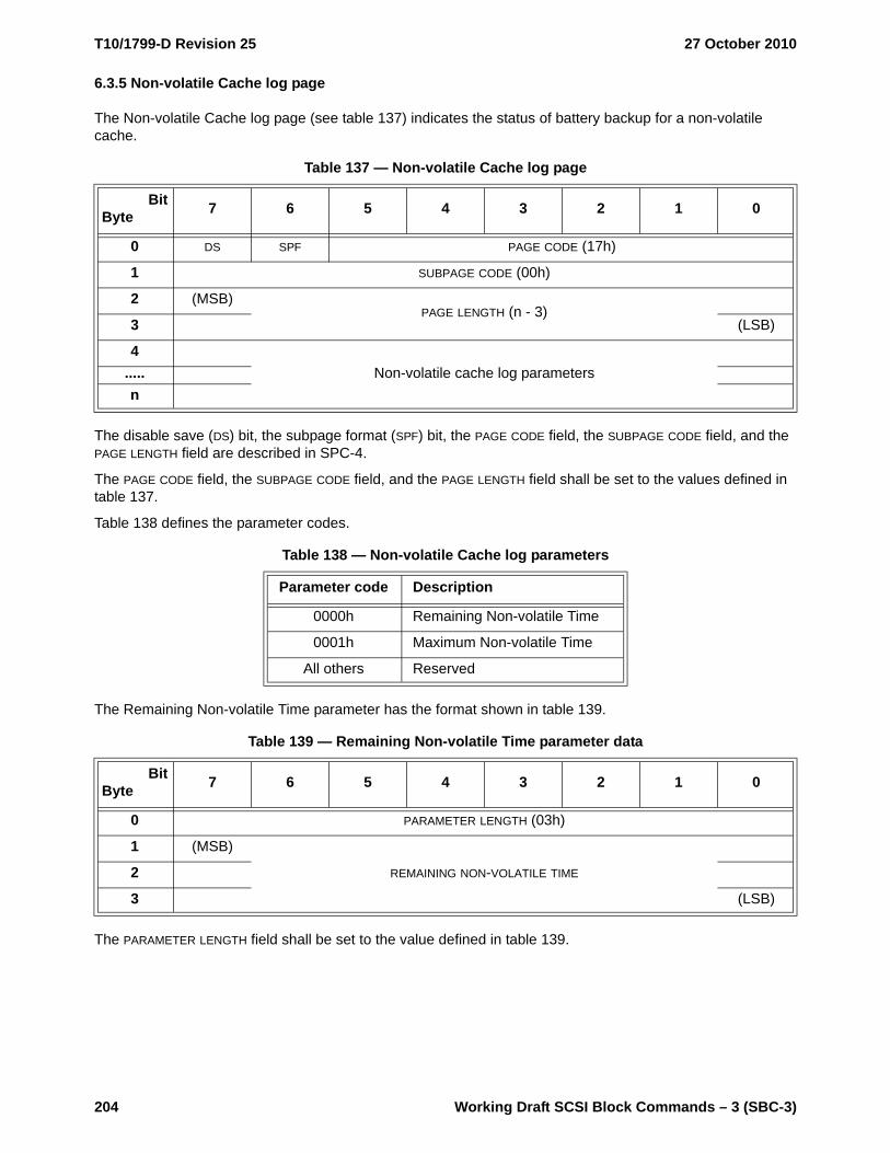
T10/1799-D Revision 25 27 October 2010
204 Working Draft SCSI Block Commands – 3 (SBC-3)
6.3.5 Non-volatile Cache log page
The Non-volatile Cache log page (see table 137) indicates the status of battery backup for a non-volatile cache.
The disable save (DS) bit, the subpage format (SPF) bit, the PAGE CODE field, the SUBPAGE CODE field, and the PAGE LENGTH field are described in SPC-4.
The PAGE CODE field, the SUBPAGE CODE field, and the PAGE LENGTH field shall be set to the values defined in table 137.
Table 138 defines the parameter codes.
The Remaining Non-volatile Time parameter has the format shown in table 139.
The PARAMETER LENGTH field shall be set to the value defined in table 139.
Table 137 — Non-volatile Cache log page
BitByte 7 6 5 4 3 2 1 0
0 DS SPF PAGE CODE (17h)
1 SUBPAGE CODE (00h)
2 (MSB)PAGE LENGTH (n - 3)
3 (LSB)
4Non-volatile cache log parameters.....
n
Table 138 — Non-volatile Cache log parameters
Parameter code Description
0000h Remaining Non-volatile Time
0001h Maximum Non-volatile Time
All others Reserved
Table 139 — Remaining Non-volatile Time parameter data
BitByte 7 6 5 4 3 2 1 0
0 PARAMETER LENGTH (03h)
1 (MSB)
REMAINING NON-VOLATILE TIME2
3 (LSB)

27 October 2010 T10/1799-D Revision 25
Working Draft SCSI Block Commands – 3 (SBC-3) 205
The REMAINING NON-VOLATILE TIME field is defined in table 140.
The Maximum Non-volatile Time parameter has the format shown in table 141.
The PARAMETER LENGTH field shall be set to the value defined in table 141.
The MAXIMUM NON-VOLATILE TIME field is defined in table 142.
Table 140 — REMAINING NON-VOLATILE TIME field
Code Description
00_0000h Non-volatile cache is volatile, either permanently or temporarily (e.g., if batteries need to be recharged).
00_0001h Non-volatile cache is expected to remain non-volatile for an unknown amount of time (e.g., if battery status is unknown)
00_0002h to FF_FFFEh Non-volatile cache is expected to remain non-volatile for the number of minutes indicated (e.g., battery-backed random access memory).
FF_FFFFh Non-volatile cache is indefinitely non-volatile.
Table 141 — Maximum Non-volatile Time parameter data
BitByte 7 6 5 4 3 2 1 0
0 PARAMETER LENGTH (03h)
1 (MSB)
MAXIMUM NON-VOLATILE TIME2
3 (LSB)
Table 142 — MAXIMUM NON-VOLATILE TIME field
Code Description
00_0000h Non-volatile cache is volatile
00_0001h Reserved
00_0002h to FF_FFFEhNon-volatile cache is capable of being non-volatile for the estimated number of minutes indicated. If the time is based on batteries, it shall be based on the last full charge capacity rather than the design capacity of the batteries.
FF_FFFFh Non-volatile cache is indefinitely non-volatile.
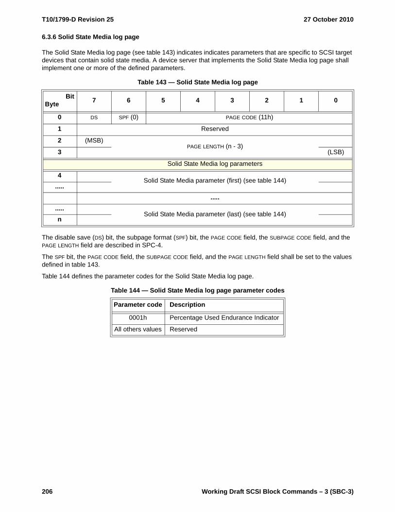
T10/1799-D Revision 25 27 October 2010
206 Working Draft SCSI Block Commands – 3 (SBC-3)
6.3.6 Solid State Media log page
The Solid State Media log page (see table 143) indicates indicates parameters that are specific to SCSI target devices that contain solid state media. A device server that implements the Solid State Media log page shall implement one or more of the defined parameters.
The disable save (DS) bit, the subpage format (SPF) bit, the PAGE CODE field, the SUBPAGE CODE field, and the PAGE LENGTH field are described in SPC-4.
The SPF bit, the PAGE CODE field, the SUBPAGE CODE field, and the PAGE LENGTH field shall be set to the values defined in table 143.
Table 144 defines the parameter codes for the Solid State Media log page.
Table 143 — Solid State Media log page
BitByte 7 6 5 4 3 2 1 0
0 DS SPF (0) PAGE CODE (11h)
1 Reserved
2 (MSB)PAGE LENGTH (n - 3)
3 (LSB)
Solid State Media log parameters
4Solid State Media parameter (first) (see table 144)
..........
.....Solid State Media parameter (last) (see table 144)
n
Table 144 — Solid State Media log page parameter codes
Parameter code Description
0001h Percentage Used Endurance Indicator
All others values Reserved
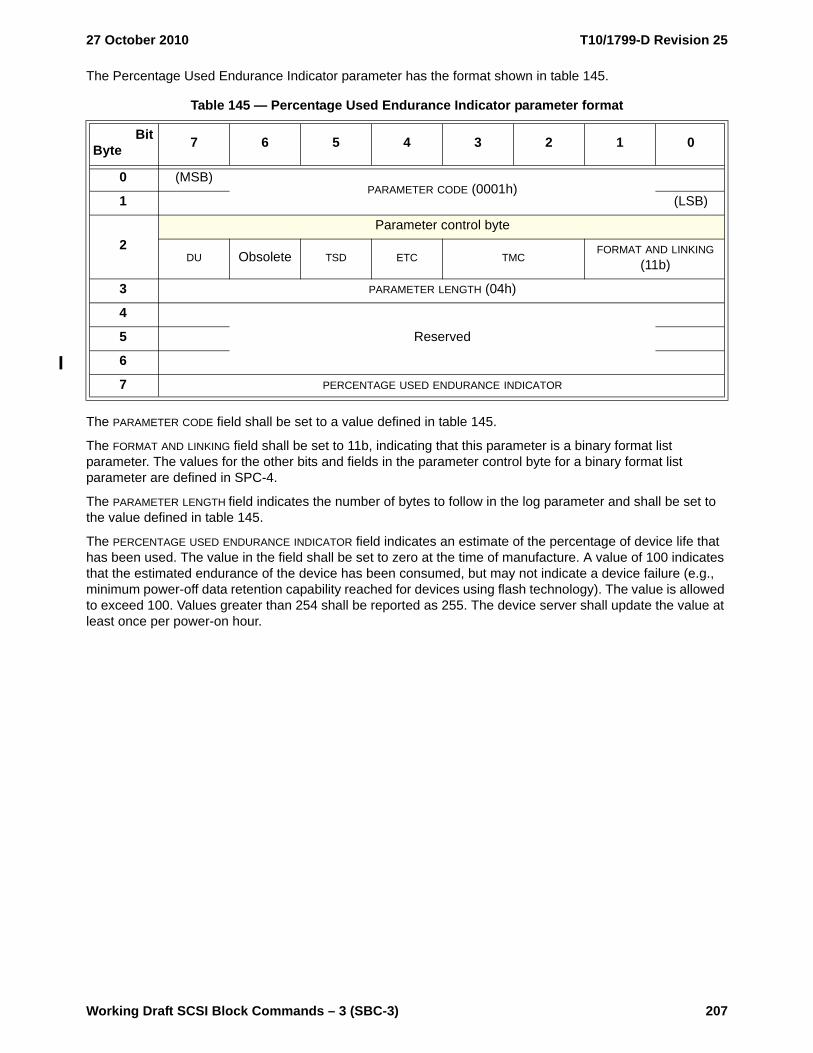
27 October 2010 T10/1799-D Revision 25
Working Draft SCSI Block Commands – 3 (SBC-3) 207
The Percentage Used Endurance Indicator parameter has the format shown in table 145.
The PARAMETER CODE field shall be set to a value defined in table 145.
The FORMAT AND LINKING field shall be set to 11b, indicating that this parameter is a binary format list parameter. The values for the other bits and fields in the parameter control byte for a binary format list parameter are defined in SPC-4.
The PARAMETER LENGTH field indicates the number of bytes to follow in the log parameter and shall be set to the value defined in table 145.
The PERCENTAGE USED ENDURANCE INDICATOR field indicates an estimate of the percentage of device life that has been used. The value in the field shall be set to zero at the time of manufacture. A value of 100 indicates that the estimated endurance of the device has been consumed, but may not indicate a device failure (e.g., minimum power-off data retention capability reached for devices using flash technology). The value is allowed to exceed 100. Values greater than 254 shall be reported as 255. The device server shall update the value at least once per power-on hour.
Table 145 — Percentage Used Endurance Indicator parameter format
BitByte 7 6 5 4 3 2 1 0
0 (MSB)PARAMETER CODE (0001h)
1 (LSB)
2Parameter control byte
DU Obsolete TSD ETC TMCFORMAT AND LINKING
(11b)
3 PARAMETER LENGTH (04h)
4
Reserved5
6
7 PERCENTAGE USED ENDURANCE INDICATOR

T10/1799-D Revision 25 27 October 2010
208 Working Draft SCSI Block Commands – 3 (SBC-3)
6.4 Mode parameters
6.4.1 Mode parameters overview
This subclause defines the mode pages and block descriptors (see 6.4.2) used by direct-access block devices.
The mode pages and their corresponding page codes and subpage codes for direct-access block devices are shown in table 146.
The mode parameter list, including the mode parameter header, is described in SPC-4. Direct-access block devices support zero or one mode parameter block descriptors (i.e., the block descriptor is shared by all the logical blocks on the medium) (see 6.4.2).
Table 146 — Mode page codes and subpage codes for direct-access block devices
Mode page name Page code Subpage code Reference
Application Tag mode page 0Ah 02h 6.4.3
Background Control mode page 1Ch 01h 6.4.4
Caching mode page 08h 00h 6.4.5
Control Extension mode page 0Ah 01h SPC-4
Control mode page 0Ah 00h SPC-4
Disconnect-Reconnect mode page 02h 00h SPC-4
Enclosure Services Management mode page a 14h 00h SES-2
Informational Exceptions Control mode page 1Ch 00h SPC-4
Logical Block Provisioning mode page 1Ch 02h 6.4.6
Power Condition mode page 1Ah 00h SPC-4
Protocol-Specific LUN mode page 18h 00h SPC-4
Protocol-Specific Port mode page 19h 00h SPC-4
Read-Write Error Recovery mode page 01h 00h 6.4.7
Return all mode pages and subpages b 3Fh FFh SPC-4
Return all mode pages only (i.e., not including subpages) b 3Fh 00h SPC-4
Return all subpages for the specified mode page code b 00h to 3Eh FFh SPC-4
Verify Error Recovery mode page 07h 00h 6.4.8
XOR Control mode page 10h 00h 6.4.9
Obsolete c
Vendor specific d
Reservedall other page and subpage code combinations for direct-access block devices
SPC-4 contains a listing of mode page and subpage codes in numeric order.a Valid only if the ENCSERV bit is set to one in the standard INQUIRY data (see SPC-4).b Valid only for the MODE SENSE command.c The following mode page codes are obsolete: 03h, 04h, 05h, 09h, 0Bh, 0Ch, and 0Dh.d The following mode page code and subpage code combinations are vendor specific and do not require
a page format: mode page code 00h with subpage code 00h and mode page codes 20h to 3Eh with all subpage codes.

27 October 2010 T10/1799-D Revision 25
Working Draft SCSI Block Commands – 3 (SBC-3) 209
The MEDIUM TYPE field in the mode parameter header (see SPC-4) shall be set to 00h.
The DEVICE-SPECIFIC PARAMETER field in the mode parameter header (see SPC-4) is defined for direct-access block devices in table 147.
When used with the MODE SELECT command, the write protect (WP) bit is not defined.
When used with the MODE SENSE command, a WP bit set to one indicates that the medium is write-protected. A WP bit set to zero indicates that the medium is not write-protected. When the software write protect (SWP) bit in the Control mode page (see SPC-4) is set to one, the WP bit shall be set to one. When the SWP bit in the Control mode page is set to zero, the WP bit shall be set to one if the medium is write-protected (e.g., due to mechanisms outside the scope of this standard) or zero if the medium is not write-protected.
When used with the MODE SELECT command, the DPOFUA bit is reserved.
When used with the MODE SENSE command, a DPOFUA bit set to zero indicates that the device server does not support the DPO and FUA bits. When used with the MODE SENSE command, a DPOFUA bit set to one indicates that the device server supports the DPO and FUA bits (see 4.13).
6.4.2 Mode parameter block descriptors
6.4.2.1 Mode parameter block descriptors overview
If the device server returns a mode parameter block descriptor, then the device server shall return a short LBA mode parameter block descriptor (see 6.4.2.2) in the mode parameter data in response to:
a) a MODE SENSE (6) command; orb) a MODE SENSE (10) command with the LLBAA bit set to zero.
If the device server returns a mode parameter block descriptor and the number of logical blocks is greater than FFFF_FFFFh, then the device server may return a long LBA mode parameter block descriptor (see 6.4.2.3) in the mode parameter data in response to a MODE SENSE (10) command with the LLBAA bit set to one.
If the application client sends a mode parameter block descriptor in the mode parameter list, then the application client shall send a short LBA mode parameter block descriptor (see 6.4.2.2) for a MODE SELECT (6) command.
If the application client sends a mode parameter block descriptor in the mode parameter list, then the application client may send a long LBA mode parameter block descriptor (see 6.4.2.3) for a MODE SELECT (10) command.
Support for the mode parameter block descriptors is optional. The device server shall establish a unit attention condition with the additional sense code set to MODE PARAMETERS CHANGED (see SPC-4 and SAM-4) when the block descriptor values are changed.
Table 147 — DEVICE-SPECIFIC PARAMETER field for direct-access block devices
Bit 7 6 5 4 3 2 1 0
WP Reserved DPOFUA Reserved
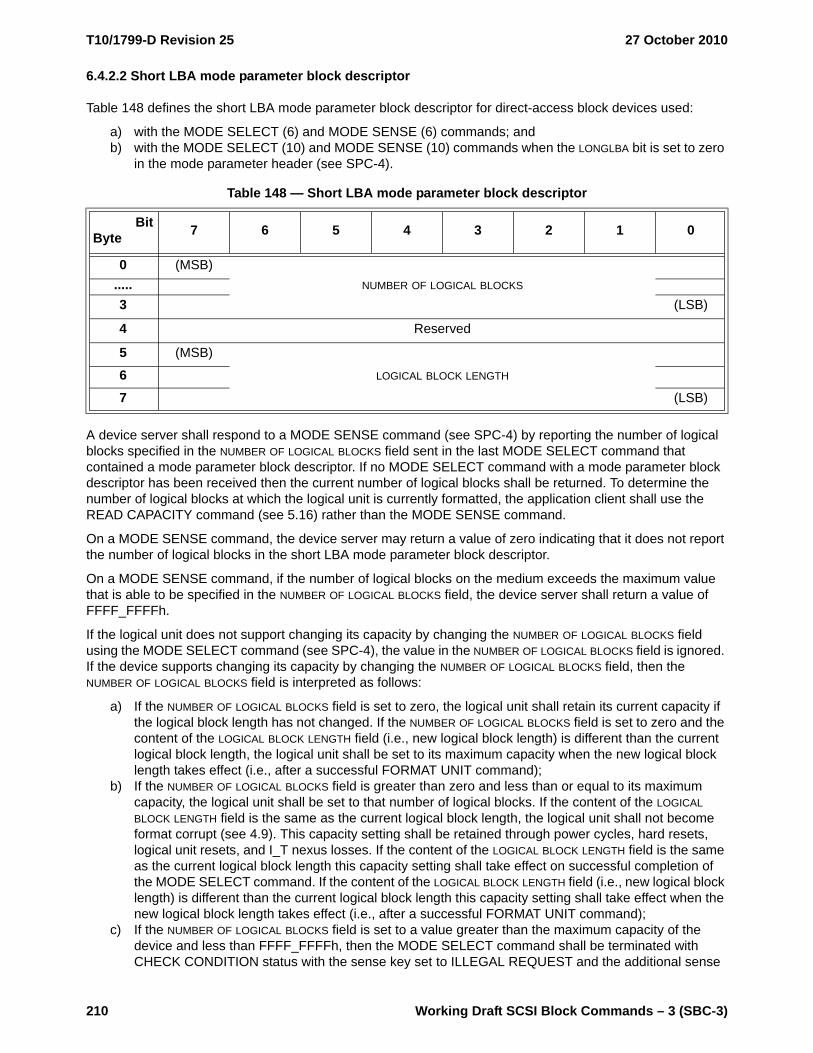
T10/1799-D Revision 25 27 October 2010
210 Working Draft SCSI Block Commands – 3 (SBC-3)
6.4.2.2 Short LBA mode parameter block descriptor
Table 148 defines the short LBA mode parameter block descriptor for direct-access block devices used:
a) with the MODE SELECT (6) and MODE SENSE (6) commands; andb) with the MODE SELECT (10) and MODE SENSE (10) commands when the LONGLBA bit is set to zero
in the mode parameter header (see SPC-4).
A device server shall respond to a MODE SENSE command (see SPC-4) by reporting the number of logical blocks specified in the NUMBER OF LOGICAL BLOCKS field sent in the last MODE SELECT command that contained a mode parameter block descriptor. If no MODE SELECT command with a mode parameter block descriptor has been received then the current number of logical blocks shall be returned. To determine the number of logical blocks at which the logical unit is currently formatted, the application client shall use the READ CAPACITY command (see 5.16) rather than the MODE SENSE command.
On a MODE SENSE command, the device server may return a value of zero indicating that it does not report the number of logical blocks in the short LBA mode parameter block descriptor.
On a MODE SENSE command, if the number of logical blocks on the medium exceeds the maximum value that is able to be specified in the NUMBER OF LOGICAL BLOCKS field, the device server shall return a value of FFFF_FFFFh.
If the logical unit does not support changing its capacity by changing the NUMBER OF LOGICAL BLOCKS field using the MODE SELECT command (see SPC-4), the value in the NUMBER OF LOGICAL BLOCKS field is ignored. If the device supports changing its capacity by changing the NUMBER OF LOGICAL BLOCKS field, then the NUMBER OF LOGICAL BLOCKS field is interpreted as follows:
a) If the NUMBER OF LOGICAL BLOCKS field is set to zero, the logical unit shall retain its current capacity if the logical block length has not changed. If the NUMBER OF LOGICAL BLOCKS field is set to zero and the content of the LOGICAL BLOCK LENGTH field (i.e., new logical block length) is different than the current logical block length, the logical unit shall be set to its maximum capacity when the new logical block length takes effect (i.e., after a successful FORMAT UNIT command);
b) If the NUMBER OF LOGICAL BLOCKS field is greater than zero and less than or equal to its maximum capacity, the logical unit shall be set to that number of logical blocks. If the content of the LOGICAL BLOCK LENGTH field is the same as the current logical block length, the logical unit shall not become format corrupt (see 4.9). This capacity setting shall be retained through power cycles, hard resets, logical unit resets, and I_T nexus losses. If the content of the LOGICAL BLOCK LENGTH field is the same as the current logical block length this capacity setting shall take effect on successful completion of the MODE SELECT command. If the content of the LOGICAL BLOCK LENGTH field (i.e., new logical block length) is different than the current logical block length this capacity setting shall take effect when the new logical block length takes effect (i.e., after a successful FORMAT UNIT command);
c) If the NUMBER OF LOGICAL BLOCKS field is set to a value greater than the maximum capacity of the device and less than FFFF_FFFFh, then the MODE SELECT command shall be terminated with CHECK CONDITION status with the sense key set to ILLEGAL REQUEST and the additional sense
Table 148 — Short LBA mode parameter block descriptor
BitByte 7 6 5 4 3 2 1 0
0 (MSB)NUMBER OF LOGICAL BLOCKS.....
3 (LSB)
4 Reserved
5 (MSB)
LOGICAL BLOCK LENGTH67 (LSB)

27 October 2010 T10/1799-D Revision 25
Working Draft SCSI Block Commands – 3 (SBC-3) 211
code set to INVALID FIELD IN PARAMETER LIST. The logical unit shall retain its previous logical block descriptor settings; or
d) If the NUMBER OF LOGICAL BLOCKS field is set to FFFF_FFFFh, the logical unit shall be set to its maximum capacity. If the content of the LOGICAL BLOCK LENGTH field is the same as the current logical block length, the logical unit shall not become format corrupt (see 4.9). This capacity setting shall be retained through power cycles, hard resets, logical unit resets, and I_T nexus losses. If the content of the LOGICAL BLOCK LENGTH field is the same as the current logical block length this capacity setting shall take effect on successful completion of the MODE SELECT command. If the content of the LOGICAL BLOCK LENGTH field (i.e., new logical block length) is different than the current logical block length this capacity setting shall take effect when the new logical block length takes effect (i.e., after a successful FORMAT UNIT command).
The LOGICAL BLOCK LENGTH field specifies the length in bytes of each logical block. No change shall be made to any logical blocks on the medium until a format operation (see 5.2) is initiated by an application client.
A device server shall respond to a MODE SENSE command (see SPC-4) by reporting the length of the logical blocks as specified in the LOGICAL BLOCK LENGTH field sent in the last MODE SELECT command that contained a mode parameter block descriptor. If no MODE SELECT command with a block descriptor has been received then the current logical block length shall be returned (e.g., if the logical block length is 512 bytes and a MODE SELECT command occurs with the LOGICAL BLOCK LENGTH field set to 520 bytes, any MODE SENSE commands would return 520 in the LOGICAL BLOCK LENGTH field). To determine the logical block length at which the logical unit is currently formatted, the application client shall use the READ CAPACITY command (see 5.16) rather than the MODE SELECT command.
6.4.2.3 Long LBA mode parameter block descriptor
Table 149 defines the log LBA mode parameter block descriptor for direct-access block devices used with the MODE SELECT (10) command and MODE SENSE (10) command when the LONGLBA bit is set to one in the mode parameter header (see SPC-4).
A device server shall respond to a MODE SENSE command (see SPC-4) by reporting the number of logical blocks specified in the NUMBER OF LOGICAL BLOCKS field sent in the last MODE SELECT command that contained a mode parameter block descriptor. If no MODE SELECT command with a mode parameter block descriptor has been received then the current number of logical blocks shall be returned. To determine the number of logical blocks at which the logical unit is currently formatted, the application client shall use the READ CAPACITY command (see 5.16) rather than the MODE SENSE command.
On a MODE SENSE command, the device server may return a value of zero indicating that it does not report the number of logical blocks in the long LBA mode parameter block descriptor.
If the logical unit does not support changing its capacity by changing the NUMBER OF LOGICAL BLOCKS field using the MODE SELECT command (see SPC-4), the value in the NUMBER OF LOGICAL BLOCKS field is ignored.
Table 149 — Long LBA mode parameter block descriptor
BitByte 7 6 5 4 3 2 1 0
0 (MSB)NUMBER OF LOGICAL BLOCKS.....
7 (LSB)
8Reserved.....
11
12 (MSB)LOGICAL BLOCK LENGTH.....
15 (LSB)
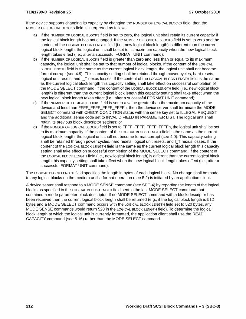
T10/1799-D Revision 25 27 October 2010
212 Working Draft SCSI Block Commands – 3 (SBC-3)
If the device supports changing its capacity by changing the NUMBER OF LOGICAL BLOCKS field, then the NUMBER OF LOGICAL BLOCKS field is interpreted as follows:
a) If the NUMBER OF LOGICAL BLOCKS field is set to zero, the logical unit shall retain its current capacity if the logical block length has not changed. If the NUMBER OF LOGICAL BLOCKS field is set to zero and the content of the LOGICAL BLOCK LENGTH field (i.e., new logical block length) is different than the current logical block length, the logical unit shall be set to its maximum capacity when the new logical block length takes effect (i.e., after a successful FORMAT UNIT command);
b) If the NUMBER OF LOGICAL BLOCKS field is greater than zero and less than or equal to its maximum capacity, the logical unit shall be set to that number of logical blocks. If the content of the LOGICAL BLOCK LENGTH field is the same as the current logical block length, the logical unit shall not become format corrupt (see 4.9). This capacity setting shall be retained through power cycles, hard resets, logical unit resets, and I_T nexus losses. If the content of the LOGICAL BLOCK LENGTH field is the same as the current logical block length this capacity setting shall take effect on successful completion of the MODE SELECT command. If the content of the LOGICAL BLOCK LENGTH field (i.e., new logical block length) is different than the current logical block length this capacity setting shall take effect when the new logical block length takes effect (i.e., after a successful FORMAT UNIT command);
c) If the NUMBER OF LOGICAL BLOCKS field is set to a value greater than the maximum capacity of the device and less than FFFF_FFFF_FFFF_FFFFh, then the device server shall terminate the MODE SELECT command with CHECK CONDITION status with the sense key set to ILLEGAL REQUEST and the additional sense code set to INVALID FIELD IN PARAMETER LIST. The logical unit shall retain its previous block descriptor settings; or
d) If the NUMBER OF LOGICAL BLOCKS field is set to FFFF_FFFF_FFFF_FFFFh, the logical unit shall be set to its maximum capacity. If the content of the LOGICAL BLOCK LENGTH field is the same as the current logical block length, the logical unit shall not become format corrupt (see 4.9). This capacity setting shall be retained through power cycles, hard resets, logical unit resets, and I_T nexus losses. If the content of the LOGICAL BLOCK LENGTH field is the same as the current logical block length this capacity setting shall take effect on successful completion of the MODE SELECT command. If the content of the LOGICAL BLOCK LENGTH field (i.e., new logical block length) is different than the current logical block length this capacity setting shall take effect when the new logical block length takes effect (i.e., after a successful FORMAT UNIT command).
The LOGICAL BLOCK LENGTH field specifies the length in bytes of each logical block. No change shall be made to any logical blocks on the medium until a format operation (see 5.2) is initiated by an application client.
A device server shall respond to a MODE SENSE command (see SPC-4) by reporting the length of the logical blocks as specified in the LOGICAL BLOCK LENGTH field sent in the last MODE SELECT command that contained a mode parameter block descriptor. If no MODE SELECT command with a block descriptor has been received then the current logical block length shall be returned (e.g., if the logical block length is 512 bytes and a MODE SELECT command occurs with the LOGICAL BLOCK LENGTH field set to 520 bytes, any MODE SENSE commands would return 520 in the LOGICAL BLOCK LENGTH field). To determine the logical block length at which the logical unit is currently formatted, the application client shall use the READ CAPACITY command (see 5.16) rather than the MODE SELECT command.

27 October 2010 T10/1799-D Revision 25
Working Draft SCSI Block Commands – 3 (SBC-3) 213
6.4.3 Application Tag mode page
6.4.3.1 Introduction
The Application Tag mode page (see table 150) specifies the Application Tag that a device server configured for protection information (see 4.19.2) shall use for each LBA range if the ATO bit in the Control mode page (see SPC-4) is set to one. The mode page policy (see SPC-4) for this page shall be shared.
If a method not defined by this standard changes the parameter data to be returned by the device server in the Application Tag mode page, then the device server shall establish a unit attention condition for the initiator port associated with every I_T nexus with the additional sense code set to MODE PARAMETERS CHANGED.
The parameters saveable (PS) bit, the subpage format (SPF) bit, the PAGE CODE field, the SUBPAGE CODE field, and the PAGE LENGTH field are defined in SPC-4.
The SPF bit, the PAGE CODE field, the SUBPAGE CODE field, and the PAGE LENGTH field shall be set to the values defined in table 150.
The application tag descriptors are defined in 6.4.3.2.
Table 150 — Application Tag mode page
BitByte 7 6 5 4 3 2 1 0
0 PS SPF (1b) PAGE CODE (0Ah)
1 SUBPAGE CODE (F0h)
2 (MSB)PAGE LENGTH (n-4)
3 (LSB)
4Reserved.....
15
Application Tag descriptors
16Application Tag descriptor (first) (see 6.4.3.2).....
23
.....
n-7Application tag descriptor (last) (see 6.4.3.2).....
n

T10/1799-D Revision 25 27 October 2010
214 Working Draft SCSI Block Commands – 3 (SBC-3)
6.4.3.2 Application Tag descriptor
The Application Tag descriptor format is described in table 151.
A LAST bit set to one specifies that this Application Tag descriptor is the last valid Application Tag descriptor in the Application Tag mode page. A LAST bit set to zero specifies that the Application Tag descriptor is not the last valid Application Tag descriptor in the Application Tag mode page.
The LOGICAL BLOCK APPLICATION TAG field specifies the value to be compared with the LOGICAL BLOCK APPLICATION TAG field associated with data read or written to the LBA.
The LOGICAL BLOCK ADDRESS field contains the starting LBA for this Application Tag descriptor. The LOGICAL BLOCK ADDRESS field in the first Application Tag descriptor shall be set to 0000_0000_0000_0000h. For subsequent Application Tag descriptors, the contents of the LOGICAL BLOCK ADDRESS field shall contain the sum of the values in:
a) the LOGICAL BLOCK ADDRESS field in the previous Application Tag descriptor; andb) the LOGICAL BLOCK COUNT field in the previous Application Tag descriptor.
The sum of the LOGICAL BLOCK ADDRESS field in the Application Tag descriptor with the LAST bit set to one and the LOGICAL BLOCK COUNT field in the Application Tag descriptor with the LAST bit set to one shall equal the RETURNED LOGICAL BLOCK ADDRESS field returned for a READ CAPACITY (16) command (see 5.16).
If an invalid combination of the LAST bit, LOGICAL BLOCK APPLICATION TAG field, and LOGICAL BLOCK ADDRESS field are sent by the application client, then the device server shall terminate the MODE SELECT command (see SPC-4) with CHECK CONDITION status with the sense key set to ILLEGAL REQUEST and the additional sense code set to INVALID FIELD IN PARAMETER LIST.
The LOGICAL BLOCK COUNT field specifies the number of logical blocks to which this Application Tag descriptor applies.
A LOGICAL BLOCK COUNT field set to 0000_0000_0000_0000h specifies that this Application Tag descriptor shall be ignored.
Table 151 — Application tag descriptor format
BitByte 7 6 5 4 3 2 1 0
0 LAST Reserved
1Reserved.....
5
6 (MSB)LOGICAL BLOCK APPLICATION TAG
7 (LSB)
8 (MSB)LOGICAL BLOCK ADDRESS.....
15 (LSB)
16 (MSB)LOGICAL BLOCK COUNT.....
23 (LSB)

27 October 2010 T10/1799-D Revision 25
Working Draft SCSI Block Commands – 3 (SBC-3) 215
6.4.4 Background Control mode page
The Background Control mode page (see table 152) provides controls over background scan operations (see 4.21). The mode page policy (see SPC-4) for this subpage shall be shared.
The parameters saveable (PS) bit, the subpage format (SPF) bit, the PAGE CODE field, the SUBPAGE CODE field, and the PAGE LENGTH field are defined in SPC-4.
The SPF bit, the PAGE CODE field, the SUBPAGE CODE field, and the PAGE LENGTH field shall be set to the values defined in table 152.
A suspend on log full (S_L_FULL) bit set to zero specifies that the device server shall continue running a background scan operation (see 4.21.1) even if the Background Scan Results log page (see 6.3.2) contains the maximum number of Background Scan log parameters (see 6.3.2.3) supported by the logical unit. A S_L_FULL bit set to one specifies that the device server shall suspend a background scan operation if the Background Scan Results log page contains the maximum number of Background scan log parameters supported by the logical unit.
A log only when intervention required (LOWIR) bit set to zero specifies that the device server shall log all suspected recoverable medium errors or unrecoverable medium errors that are identified during background scan operations in the Background Scan Results log page. A LOWIR bit set to one specifies that the device server shall only log medium errors identified during back ground scan operations in the Background Scan Results log page that require application client intervention.
An enable background medium scan (EN_BMS) bit set to zero specifies that the device server shall disable background medium scan operations (see 4.21.3). An EN_BMS bit set to one specifies that the device server shall enable background medium scan operations. If the EN_PS bit is also set to one, and a background pre-scan operation is in progress, then the logical unit shall not start a background medium scan operation until after the background pre-scan operation is halted or completed. If a background medium scan operation is in progress when the EN_BMS bit is changed from one to zero, then the logical unit shall suspend the
Table 152 — Background Control mode page
BitByte 7 6 5 4 3 2 1 0
0 PS SPF (1b) PAGE CODE (1Ch)
1 SUBPAGE CODE (01h)
2 (MSB)PAGE LENGTH (000Ch)
3 (LSB)
4 Reserved S_L_FULL LOWIR EN_BMS
5 Reserved EN_PS
6 (MSB)BACKGROUND MEDIUM SCAN INTERVAL TIME
7 (LSB)
8 (MSB)BACKGROUND PRE-SCAN TIME LIMIT
9 (LSB)
10 (MSB)MINIMUM IDLE TIME BEFORE BACKGROUND SCAN
11 (LSB)
12 (MSB)MAXIMUM TIME TO SUSPEND BACKGROUND SCAN
13 (LSB)
14Reserved
15

T10/1799-D Revision 25 27 October 2010
216 Working Draft SCSI Block Commands – 3 (SBC-3)
background medium scan operation before the device server completes the MODE SELECT command, and the background medium scan shall remain suspended until the EN_BMS bit is set to one, at which time the logical unit shall resume the background medium scan operation beginning with the logical block being tested when the background medium scan operation was suspended.
An enable pre-scan (EN_PS) bit set to zero specifies that the device server shall disable background pre-scan operations (see 4.21.2). If a background pre-scan operation is in progress when the EN_PS bit is changed from a one to a zero, then the logical unit shall halt the background pre-scan operation before the device server completes the MODE SELECT command. An EN_PS bit set to one specifies that the logical unit shall start a background pre-scan operation after the next power on. Once a logical unit has completed a background pre-scan operation, the logical unit shall not perform another background pre-scan operation unless the EN_PS bit is set to zero, then set to one, and another power on occurs.
The BACKGROUND MEDIUM SCAN INTERVAL TIME field specifies the minimum time, in hours, between the start of one background scan operation and the start of the next background medium scan operation. If the current background scan operation takes longer than the value specified in the BACKGROUND MEDIUM SCAN INTERVAL TIME field, then the logical unit shall:
a) continue the current background scan operation until that background scan operation is complete; and
b) start the next background medium scan operation upon completion of the current background scan operation.
The BACKGROUND PRE-SCAN TIME LIMIT field specifies the maximum time, in hours, for a background pre-scan operation to complete. If the background pre-scan operation does not complete within the specified time then the device server shall halt the background pre-scan operation. A value of zero specifies an unlimited timeout value.
The MINIMUM IDLE TIME BEFORE BACKGROUND SCAN field specifies the time, in milliseconds, that the logical unit shall be idle after suspending a background scan operation before resuming a background scan operation (e.g., after the device server has completed all of the commands in the task set).
The MAXIMUM TIME TO SUSPEND BACKGROUND SCAN field specifies the time, in milliseconds, that the device server should take to start processing a command received while a logical unit is performing a background scan operation.

27 October 2010 T10/1799-D Revision 25
Working Draft SCSI Block Commands – 3 (SBC-3) 217
6.4.5 Caching mode page
The Caching mode page (see table 153) defines the parameters that affect the use of the cache.
The parameters saveable (PS) bit, the subpage format (SPF) bit, the PAGE CODE field, the SUBPAGE CODE field, and the PAGE LENGTH field are defined in SPC-4.
The SPF bit, the PAGE CODE field, the SUBPAGE CODE field, and the PAGE LENGTH field shall be set to the values defined in table 153.
An initiator control (IC) enable bit set to one specifies that the device server use one of the following fields to control the caching algorithm rather than the device server’s own adaptive algorithm:
a) the NUMBER OF CACHE SEGMENTS field, if the SIZE bit is set to zero; orb) the CACHE SEGMENT SIZE field, if the SIZE bit is set to one.
An abort pre-fetch (ABPF) bit set to one when the DRA bit is set to zero specifies that the device server abort a pre-fetch upon receipt of a new command. An ABPF bit set to one takes precedence over the value specified in the MINIMUM PRE-FETCH field. An ABPF bit set to zero when the DRA bit set to zero specifies that the termination of any active pre-fetch is dependent upon Caching mode page bytes 4 through 11 and is vendor specific.
A caching analysis permitted (CAP) bit set to one specifies that the device server perform caching analysis during subsequent operations. A CAP bit set to zero specifies that caching analysis be disabled (e.g., to reduce overhead time or to prevent nonpertinent operations from impacting tuning values).
Table 153 — Caching mode page
BitByte 7 6 5 4 3 2 1 0
0 PS SPF (0b) PAGE CODE (08h)
1 PAGE LENGTH (12h)
2 IC ABPF CAP DISC SIZE WCE MF RCD
3 DEMAND READ RETENTION PRIORITY WRITE RETENTION PRIORITY
4 (MSB)DISABLE PRE-FETCH TRANSFER LENGTH
5 (LSB)
6 (MSB)MINIMUM PRE-FETCH
7 (LSB)
8 (MSB)MAXIMUM PRE-FETCH
9 (LSB)
10 (MSB)MAXIMUM PRE-FETCH CEILING
11 (LSB)
12 FSW LBCSS DRA vendor specific Reserved NV_DIS
13 NUMBER OF CACHE SEGMENTS
14 (MSB)CACHE SEGMENT SIZE
15 (LSB)
16 Reserved
17
Obsolete18
19

T10/1799-D Revision 25 27 October 2010
218 Working Draft SCSI Block Commands – 3 (SBC-3)
A discontinuity (DISC) bit set to one specifies that the device server continue the pre-fetch across time discontinuities (e.g., across cylinders) up to the limits of the buffer, or segment, space available for the pre-fetch. A DISC bit set to zero specifies that pre-fetches be truncated or wrapped at time discontinuities.
A size enable (SIZE) bit set to one specifies that the CACHE SEGMENT SIZE field be used to control caching segmentation. A SIZE bit set to zero specifies that the NUMBER OF CACHE SEGMENTS field be used to control caching segmentation. Simultaneous use of both the number of segments and the segment size is vendor specific.
A writeback cache enable (WCE) bit set to zero specifies that the device server shall complete a WRITE command with GOOD status only after writing all of the data to the medium without error. A WCE bit set to one specifies that the device server may complete a WRITE command with GOOD status after receiving the data without error and prior to having written the data to the medium.
A multiplication factor (MF) bit set to zero specifies that the device server shall interpret the MINIMUM PRE-FETCH field and the MAXIMUM PRE-FETCH field in terms of the number of logical blocks for each of the respective types of pre-fetch. An MF bit set to one specifies that the device server shall interpret the MINIMUM PRE-FETCH field and the MAXIMUM PRE-FETCH field to be specified in terms of a scalar number that, when multiplied by the number of logical blocks to be transferred for the current command, yields the number of logical blocks for each of the respective types of pre-fetch.
A read cache disable (RCD) bit set to zero specifies that the device server may return data requested by a READ command by accessing either the cache or medium. A RCD bit set to one specifies that the device server shall transfer all of the data requested by a READ command from the medium (i.e., data shall not be transferred from the cache).
The DEMAND READ RETENTION PRIORITY field (see table 154) specifies the retention priority the device server should assign for data read into the cache that has also been transferred to the data-in buffer.
Table 154 — DEMAND READ RETENTION PRIORITY field
Code Description
0h The device server should not distinguish between retaining the indicated data and data placed into the cache by other means (e.g., pre-fetch).
1h The device server should replace data put into the cache via a READ command sooner (i.e., read data has lower priority) than data placed into the cache by other means (e.g., pre-fetch).
2h to Eh Reserved
FhThe device server should not replace data put into the cache via a READ command if there is other data in the cache that was placed into the cache by other means (e.g., pre-fetch) and the data in the cache may be replaced.

27 October 2010 T10/1799-D Revision 25
Working Draft SCSI Block Commands – 3 (SBC-3) 219
The WRITE RETENTION PRIORITY field (see table 155) specifies the retention priority the device server should assign for data written into the cache that has also been transferred from the cache to the medium.
An anticipatory pre-fetch occurs when data is placed in the cache that has not been requested. This may happen in conjunction with the reading of data that has been requested. The DISABLE PRE-FETCH TRANSFER LENGTH field, the MINIMUM PRE-FETCH field, the MAXIMUM PRE-FETCH field, and the MAXIMUM PRE-FETCH CEILING field give an indication to the device server how it should manage the cache based on the most recent READ command. An anticipatory pre-fetch may occur based on other information. These fields are only recommendations to the device server and should not cause a CHECK CONDITION to occur if the device server is not able to satisfy the request.
The DISABLE PRE-FETCH TRANSFER LENGTH field specifies the selective disabling of anticipatory pre-fetch on long transfer lengths. The value in this field is compared to the transfer length requested by a READ command. If the transfer length is greater than the disable pre-fetch transfer length, then an anticipatory pre-fetch is not done for the command. Otherwise the device server should attempt an anticipatory pre-fetch. If the DISABLE PRE-FETCH TRANSFER LENGTH field is set to zero, then all anticipatory pre-fetching is disabled for any request for data, including those with a transfer length of zero.
The MINIMUM PRE-FETCH field specifies the number of logical blocks to pre-fetch regardless of the delays it might cause in processing subsequent commands. The field contains either:
a) a number of logical blocks, if the MF bit is set to zero; orb) a scalar multiplier of the value in the TRANSFER LENGTH field, if the MF bit is set to one.
The pre-fetching operation begins at the logical block after the last logical block of a READ command. Pre-fetching shall always halt when it reaches the last logical block on the medium. Errors that occur during the pre-fetching operation shall not be reported to the application client unless the device server is unable to process subsequent commands correctly as a result of the error. In this case the error may be reported either as an error for that subsequent command, or as a deferred error, at the discretion of the device server and according to the rules for reporting deferred errors (see SPC-4).
If the pre-fetch has read more than the amount of data specified by the MINIMUM PRE-FETCH field, then pre-fetching should be terminated whenever another command enters the enabled state (see SAM-4). This requirement is ignored when the MINIMUM PRE-FETCH field value is equal to the MAXIMUM PRE-FETCH field value.
The MAXIMUM PRE-FETCH field specifies the number of logical blocks to pre-fetch if the pre-fetch does not delay processing of subsequent commands. The field contains either:
a) a number of logical blocks, if the MF bit is set to zero; orb) a scalar multiplier of the value in the TRANSFER LENGTH field, if the MF bit is set to one.
The MAXIMUM PRE-FETCH field contains the maximum amount of data to pre-fetch as a result of one READ command. It is used in conjunction with the DISABLE PRE-FETCH TRANSFER LENGTH field and MAXIMUM PRE- FETCH CEILING field to trade off pre-fetching new data with displacing old data already stored in the cache.
Table 155 — WRITE RETENTION PRIORITY field
Code Description
0h The device server should not distinguish between retaining the indicated data and data placed into the cache by other means (e.g., pre-fetch).
1hThe device server should replace data put into the cache during a WRITE command or a WRITE AND VERIFY command sooner (i.e., has lower priority) than data placed into the cache by other means (e.g., pre-fetch).
2h to Eh Reserved
FhThe device server should not replace data put into the cache during a WRITE command or a WRITE AND VERIFY command if there is other data in the cache that was placed into the cache by other means (e.g., pre-fetch) and the data in the cache may be replaced.

T10/1799-D Revision 25 27 October 2010
220 Working Draft SCSI Block Commands – 3 (SBC-3)
The MAXIMUM PRE-FETCH CEILING field specifies an upper limit on the number of logical blocks computed as the maximum pre-fetch. If this number of logical blocks is greater than the value in the MAXIMUM PRE-FETCH field, then the number of logical blocks to pre-fetch shall be truncated to the value stored in the MAXIMUM PRE-FETCH CEILING field.
NOTE 23 - If the MF bit is set to one the MAXIMUM PRE-FETCH CEILING field is useful in limiting the amount of data to be pre-fetched.
A force sequential write (FSW) bit set to one specifies that, for commands writing to more than one logical block, the device server shall write the logical blocks to the medium in ascending sequential order. An FSW bit set to zero specifies that the device server may reorder the sequence of writing logical blocks (e.g., in order to achieve faster command completion).
A logical block cache segment size (LBCSS) bit set to one specifies that the CACHE SEGMENT SIZE field units shall be interpreted as logical blocks. An LBCSS bit set to zero specifies that the CACHE SEGMENT SIZE field units shall be interpreted as bytes. The LBCSS shall not impact the units of other fields.
A disable read-ahead (DRA) bit set to one specifies that the device server shall not read into the pre-fetch buffer any logical blocks beyond the addressed logical block(s). A DRA bit set to zero specifies that the device server may continue to read logical blocks into the pre-fetch buffer beyond the addressed logical block(s).
The NUMBER OF CACHE SEGMENTS field specifies the number of segments into which the device server shall divide the cache.
The CACHE SEGMENT SIZE field specifies the segment size in bytes if the LBCSS bit is set to zero or in logical blocks if the LBCSS bit is set to one. The CACHE SEGMENT SIZE field is valid only when the SIZE bit is set to one.
An NV_DIS bit set to one specifies that the device server shall disable a non-volatile cache and indicates that a non-volatile cache is supported but disabled. An NV_DIS bit set to zero specifies that the device server may use a non-volatile cache and indicates that a non-volatile cache may be present and enabled.

27 October 2010 T10/1799-D Revision 25
Working Draft SCSI Block Commands – 3 (SBC-3) 221
6.4.6 Logical Block Provisioning mode page
6.4.6.1 Introduction
The Logical Block Provisioning mode page (see table 156) specifies the parameters that a device server that supports logical block provisioning threshold values (see 4.7.3.8) shall use to report logical block provisioning threshold notifications (see 4.7.3.8.4). The mode page policy (see SPC-4) for this page shall be shared.
If a method not defined by this standard changes the parameter data to be returned by a device server in the Logical Block Provisioning mode page, then the device server shall establish a unit attention condition for the initiator port associated with every I_T nexus with the additional sense code set to MODE PARAMETERS CHANGED.
The parameters saveable (PS) bit, the subpage format (SPF) bit, the PAGE CODE field, the SUBPAGE CODE field, and the PAGE LENGTH field are defined in SPC-4.
The SPF bit, the PAGE CODE field, the SUBPAGE CODE field, and the PAGE LENGTH field shall be set to the values defined in table 156.
A single initiator threshold unit attention (SITUA) bit set to one indicates that the logical block provisioning threshold notification unit attention condition is established on a single I_T nexus as described in 4.7.3.8.4. A SITUA bit set to zero indicates that the logical block provisioning threshold notification unit attention condition is established on multiple I_T nexuses as described in 4.7.3.8.4.
The threshold descriptors are defined in 6.4.6.2.
Table 156 — Logical Block Provisioning mode page
BitByte 7 6 5 4 3 2 1 0
0 PS SPF (1b) PAGE CODE (1Ch)
1 SUBPAGE CODE (02h)
2 (MSB)PAGE LENGTH (n-4)
3 (LSB)
4 Reserved SITUA
5Reserved.....
15
Threshold descriptors
16Threshold descriptor (first) (see 6.4.6.2).....
23
.....
n-7Threshold descriptor (last) (see 6.4.6.2).....
n
T10/1799-D Revision 25 27 October 2010
222 Working Draft SCSI Block Commands – 3 (SBC-3)
6.4.6.2 Threshold descriptor format
The threshold descriptor format is described in table 157.
An ENABLED bit set to one specifies that the threshold is enabled. An ENABLED bit set to zero specifies that the threshold is disabled.
The THRESHOLD TYPE field (see table 158) specifies the type of this threshold.
The THRESHOLD ARMING field (see table 159) specifies the arming method used for operation of this threshold.
The THRESHOLD RESOURCE field contains the low order byte of Logical Block Provisioning log page parameter codes less than 0100h (see table 135).
The THRESHOLD COUNT field specifies the center of the threshold range for this threshold expressed as a number of threshold sets (i.e., the number LBA mapping resources expressed as a number of threshold sets).
Table 157 — Threshold descriptor format
BitByte 7 6 5 4 3 2 1 0
0 ENABLED Reserved THRESHOLD TYPE THRESHOLD ARMING
1 THRESHOLD RESOURCE
2Reserved
3
4 (MSB)THRESHOLD COUNT.....
7 (LSB)
Table 158 — Threshold type field
Code Description
000bThe threshold count field specifies a soft threshold and, if the threshold is enabled, then, when the threshold is reached, the device server shall establish a unit attention condition as described in 4.7.3.8.4.
All others Reserved
Table 159 — Threshold arming field
Code Description Reference
000b The threshold operates as an armed decreasing threshold. 4.7.3.8.2
001b The threshold operates as an armed increasing threshold. 4.7.3.8.3
All others Reserved

27 October 2010 T10/1799-D Revision 25
Working Draft SCSI Block Commands – 3 (SBC-3) 223
6.4.7 Read-Write Error Recovery mode page
The Read-Write Error Recovery mode page (see table 160) specifies the error recovery parameters the device server shall use during any command that performs a read or write operation to the medium (e.g., READ command, WRITE command, or a WRITE AND VERIFY command).
The parameters saveable (PS) bit, the subpage format (SPF) bit, the PAGE CODE field, the SUBPAGE CODE field, and the PAGE LENGTH field are defined in SPC-4.
The SPF bit, the PAGE CODE field, the SUBPAGE CODE field, and the PAGE LENGTH field shall be set to the values defined in table 160.
An automatic write reassignment enabled (AWRE) bit set to zero specifies that the device server shall not perform automatic reassignment of defective logical blocks during write operations.
An AWRE bit set to one specifies that the device server shall enable automatic reassignment of defective logical blocks during write operations. The automatic reassignment shall be performed only if the device server has the valid data (e.g., original data in a buffer or recovered from the medium). The valid data shall be placed in the reassigned logical block. The device server shall report any failures that occur during the reassignment operation. Error reporting as specified by the error recovery bits (i.e., the EER bit, the PER bit, the DTE bit, and the DCR bit) shall be performed only after completion of the reassignment. See the REASSIGN BLOCKS command (see 5.21) for error procedures.
An automatic read reassignment enabled (ARRE) bit set to zero specifies that the device server shall not perform automatic reassignment of defective logical blocks during read operations.
An ARRE bit set to one specifies that the device server shall enable automatic reassignment of defective logical blocks during read operations. All error recovery actions required by the error recovery bits (i.e., the EER bit, the PER bit, the DTE bit, and the DCR bit) shall be processed. The automatic reassignment shall then be performed only if the device server successfully recovers the data. The recovered data shall be placed in the reassigned logical block. The device server shall report any failures that occur during the reassignment operation. Error reporting as specified by the error recovery bits (i.e., the EER bit, the PER bit, the DTE bit, and the DCR bit) shall be performed only after completion of the reassignment operation. See the REASSIGN BLOCKS command (see 5.21) for error procedures.
Table 160 — Read-Write Error Recovery mode page
BitByte 7 6 5 4 3 2 1 0
0 PS SPF (0b) PAGE CODE (01h)
1 PAGE LENGTH (0Ah)
2 AWRE ARRE TB RCError recovery bits
EER PER DTE DCR
3 READ RETRY COUNT
4 Obsolete
5 Obsolete
6 Obsolete
7 TPERE Reserved Restricted for MMC-6
8 WRITE RETRY COUNT
9 Reserved
10 (MSB)RECOVERY TIME LIMIT
11 (LSB)

T10/1799-D Revision 25 27 October 2010
224 Working Draft SCSI Block Commands – 3 (SBC-3)
A transfer block (TB) bit set to zero specifies that if an unrecovered read error occurs during a read operation, then the device server shall not transfer any data for the logical block to the data-in buffer. A TB bit set to one specifies that if an unrecovered read error occurs during a read operation, then the device server shall transfer pseudo read data before returning CHECK CONDITION status. The data returned in this case is vendor specific. The TB bit does not affect the action taken for recovered read errors.
A read continuous (RC) bit set to zero specifies that error recovery operations that cause delays during the data transfer are acceptable. Data shall not be fabricated.
An RC bit set to one specifies the device server shall transfer the entire requested length of data without adding delays during the data transfer to perform error recovery procedures. The device server may transfer pseudo read data in order to maintain a continuous flow of data. The device server shall assign priority to the RC bit over conflicting bits within this byte.
NOTE 24 - The RC bit may be set to one in image processing, audio, or video applications.
An enable early recovery (EER) bit set to one specifies that the device server shall use the most expedient form of error recovery first. An EER bit set to zero specifies that the device server shall use an error recovery procedure that minimizes the risk of error mis-detection or mis-correction. This bit only applies to data error recovery and it does not affect positioning retries.
NOTE 25 - An EER bit set to one may imply an increase in the probability of error mis-detection or mis-correction. An EER bit set to zero allows the specified retry limit to be exhausted prior to using additional information (e.g., ECC bytes) to correct the error.
A post error (PER) bit set to one specifies that if a recovered read error occurs during a command performing a read or write operation, then the device server shall terminate the command with CHECK CONDITION status with the sense key set to RECOVERED ERROR. A PER bit set to zero specifies that if a recovered read error occurs during a command performing a read or write operation, then the device server shall perform error recovery procedures within the limits established by the error recovery parameters and only terminate the command with CHECK CONDITION status if the error becomes uncorrectable based on the established limits. If the DTE bit is set to one, then the PER bit shall be set to one.
A data terminate on error (DTE) bit set to one specifies that the device server shall terminate the data-in or data-out buffer transfer of a command performing a read or write operation upon detection of a recovered error. A DTE bit set to zero specifies that the device server shall not terminate the data-in or data-out buffer transfer of a command performing a read or write operation upon detection of a recovered error.
A disable correction (DCR) bit set to one specifies that additional information (e.g., ECC bytes) (see 4.5) shall not be used for data error recovery. A DCR bit set to zero allows the use of additional information (e.g., ECC bytes) for data error recovery. If the EER bit is set to one, the DCR bit shall be set to zero.

27 October 2010 T10/1799-D Revision 25
Working Draft SCSI Block Commands – 3 (SBC-3) 225
The combinations of the error recovery bits (i.e., the EER bit, the PER bit, the DTE bit, and the DCR bit) are explained in table 161.
Table 161 — Combined error recovery bit descriptions (part 1 of 3)
EER PER DTE DCR Description
0 0 0 0
The device server shall perform the full number of retries as specified in the READ RETRY COUNT field for read operations, the WRITE RETRY COUNT field for write operations, and the VERIFY RETRY COUNT field (see 6.4.8) for verify operations and shall perform error correction in an attempt to recover the data.
The device server shall not report recovered read or write errors. The device server shall terminate a command performing a read or write operation with CHECK CONDITION status before the transfer count is exhausted only if an unrecovered error is detected.
If an unrecovered read error occurs during a read operation, the transfer block (TB) bit determines whether the data for the logical block with the unrecovered read error is transferred to the data-in buffer.
0 0 0 1
The device server shall perform the full number of retries as specified in the READ RETRY COUNT field for read operations, the WRITE RETRY COUNT field for write operations, and the VERIFY RETRY COUNT field (see 6.4.8) for verify operations but shall not perform error correction in an attempt to recover the data.
The device server shall not report recovered read or write errors. The device server shall terminate a command performing a read or write operation with CHECK CONDITION status before the transfer count is exhausted only if an unrecovered error is detected.
If an unrecovered read error occurs during a read operation, the transfer block (TB) bit determines whether the data for the logical block with the unrecovered read error is transferred to the data-in buffer.
0 0 1 0Invalid mode. The PER bit shall be set to one if the DTE bit is set to one. a
0 0 1 1
0 1 0 0
The device server shall perform the full number of retries as specified in the READ RETRY COUNT field for read operations, the WRITE RETRY COUNT field for write operations, and the VERIFY RETRY COUNT field (see 6.4.8) for verify operations and shall perform error correction in an attempt to recover the data.
The device server shall terminate a command performing a read or write operation with CHECK CONDITION status before the transfer count is exhausted only if an unrecovered error is detected.
If an unrecovered read error occurs during a read operation, the transfer block (TB) bit determines whether the data for the logical block with the unrecovered read error is transferred to the data-in buffer.
If a recovered error occurs while the device server is performing a read or write operation, then, after the operation is complete, the device server shall terminate the command with CHECK CONDITION status with the sense key set to RECOVERED ERROR. The INFORMATION field in the sense data shall contain the LBA of the last recovered error that occurred during the command.
a If an invalid combination of the error recovery bits is sent by an application client, then the device server shall terminate the MODE SELECT command with CHECK CONDITION status with the sense key set to ILLEGAL REQUEST and the additional sense code set to INVALID FIELD IN PARAMETER LIST.

T10/1799-D Revision 25 27 October 2010
226 Working Draft SCSI Block Commands – 3 (SBC-3)
0 1 0 1
The device server shall perform the full number of retries as specified in the READ RETRY COUNT field for read operations, the WRITE RETRY COUNT field for write operations, and the VERIFY RETRY COUNT field (see 6.4.8) for verify operations but shall not perform error correction in an attempt to recover the data.
The device server shall terminate a command performing a read or write operation with CHECK CONDITION status before the transfer count is exhausted only if an unrecovered error is detected.
If an unrecovered read error occurs during a read operation, the transfer block (TB) bit determines whether the data for the logical block with the unrecovered read error is transferred to the data-in buffer.
If a recovered error occurs while the device server is performing a read or write operation, then, after the operation is complete, the device server shall terminate the command with CHECK CONDITION status with the sense key set to RECOVERED ERROR. The INFORMATION field in the sense data shall contain the LBA of the last recovered error that occurred during the command.
0 1 1 0
The device server shall perform the full number of retries as specified in the READ RETRY COUNT field for read operations, the WRITE RETRY COUNT field for write operations, and the VERIFY RETRY COUNT field (see 6.4.8) for verify operations and shall perform error correction in an attempt to recover the data.
The device server shall terminate a command performing a read or write operation with CHECK CONDITION status before the transfer count is exhausted if any error, either recovered or unrecovered, is detected. The INFORMATION field in the sense data shall contain the LBA of error.
If an unrecovered read error occurs during a read operation, the transfer block (TB) bit determines whether the data for the logical block with the unrecovered read error is transferred to the data-in buffer.
0 1 1 1
The device server shall perform the full number of retries as specified in the READ RETRY COUNT field for read operations, the WRITE RETRY COUNT field for write operations, and the VERIFY RETRY COUNT field (see 6.4.8) for verify operations but shall not perform error correction in an attempt to recover the data.
The device server shall terminate a command performing a read or write operation with CHECK CONDITION status before the transfer count is exhausted if any error, either recovered or unrecovered, is detected. The INFORMATION field in the sense data shall contain the LBA of the error.
If an unrecovered read error occurs during a read operation, the transfer block (TB) bit determines whether the data for the logical block with the unrecovered read error is transferred to the data-in buffer.
Table 161 — Combined error recovery bit descriptions (part 2 of 3)
EER PER DTE DCR Description
a If an invalid combination of the error recovery bits is sent by an application client, then the device server shall terminate the MODE SELECT command with CHECK CONDITION status with the sense key set to ILLEGAL REQUEST and the additional sense code set to INVALID FIELD IN PARAMETER LIST.
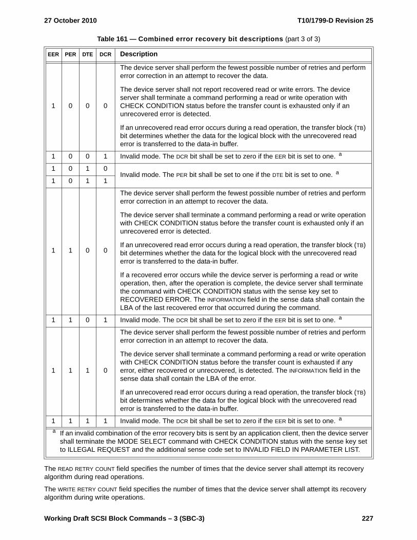
27 October 2010 T10/1799-D Revision 25
Working Draft SCSI Block Commands – 3 (SBC-3) 227
The READ RETRY COUNT field specifies the number of times that the device server shall attempt its recovery algorithm during read operations.
The WRITE RETRY COUNT field specifies the number of times that the device server shall attempt its recovery algorithm during write operations.
1 0 0 0
The device server shall perform the fewest possible number of retries and perform error correction in an attempt to recover the data.
The device server shall not report recovered read or write errors. The device server shall terminate a command performing a read or write operation with CHECK CONDITION status before the transfer count is exhausted only if an unrecovered error is detected.
If an unrecovered read error occurs during a read operation, the transfer block (TB) bit determines whether the data for the logical block with the unrecovered read error is transferred to the data-in buffer.
1 0 0 1 Invalid mode. The DCR bit shall be set to zero if the EER bit is set to one. a
1 0 1 0Invalid mode. The PER bit shall be set to one if the DTE bit is set to one. a
1 0 1 1
1 1 0 0
The device server shall perform the fewest possible number of retries and perform error correction in an attempt to recover the data.
The device server shall terminate a command performing a read or write operation with CHECK CONDITION status before the transfer count is exhausted only if an unrecovered error is detected.
If an unrecovered read error occurs during a read operation, the transfer block (TB) bit determines whether the data for the logical block with the unrecovered read error is transferred to the data-in buffer.
If a recovered error occurs while the device server is performing a read or write operation, then, after the operation is complete, the device server shall terminate the command with CHECK CONDITION status with the sense key set to RECOVERED ERROR. The INFORMATION field in the sense data shall contain the LBA of the last recovered error that occurred during the command.
1 1 0 1 Invalid mode. The DCR bit shall be set to zero if the EER bit is set to one. a
1 1 1 0
The device server shall perform the fewest possible number of retries and perform error correction in an attempt to recover the data.
The device server shall terminate a command performing a read or write operation with CHECK CONDITION status before the transfer count is exhausted if any error, either recovered or unrecovered, is detected. The INFORMATION field in the sense data shall contain the LBA of the error.
If an unrecovered read error occurs during a read operation, the transfer block (TB) bit determines whether the data for the logical block with the unrecovered read error is transferred to the data-in buffer.
1 1 1 1 Invalid mode. The DCR bit shall be set to zero if the EER bit is set to one. a
Table 161 — Combined error recovery bit descriptions (part 3 of 3)
EER PER DTE DCR Description
a If an invalid combination of the error recovery bits is sent by an application client, then the device server shall terminate the MODE SELECT command with CHECK CONDITION status with the sense key set to ILLEGAL REQUEST and the additional sense code set to INVALID FIELD IN PARAMETER LIST.
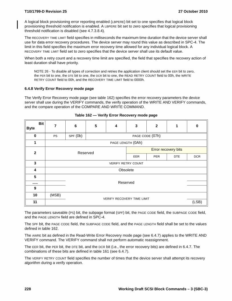
T10/1799-D Revision 25 27 October 2010
228 Working Draft SCSI Block Commands – 3 (SBC-3)
A logical block provisioning error reporting enabled (LBPERE) bit set to one specifies that logical block provisioning threshold notification is enabled. A LBPERE bit set to zero specifies that logical provisioning threshold notification is disabled (see 4.7.3.8.4).
The RECOVERY TIME LIMIT field specifies in milliseconds the maximum time duration that the device server shall use for data error recovery procedures. The device server may round this value as described in SPC-4. The limit in this field specifies the maximum error recovery time allowed for any individual logical block. A RECOVERY TIME LIMIT field set to zero specifies that the device server shall use its default value.
When both a retry count and a recovery time limit are specified, the field that specifies the recovery action of least duration shall have priority.
NOTE 26 - To disable all types of correction and retries the application client should set the EER bit to zero, the PER bit to one, the DTE bit to one, the DCR bit to one, the READ RETRY COUNT field to 00h, the WRITE RETRY COUNT field to 00h, and the RECOVERY TIME LIMIT field to 0000h.
6.4.8 Verify Error Recovery mode page
The Verify Error Recovery mode page (see table 162) specifies the error recovery parameters the device server shall use during the VERIFY commands, the verify operation of the WRITE AND VERIFY commands, and the compare operation of the COMPARE AND WRITE COMMAND.
The parameters saveable (PS) bit, the subpage format (SPF) bit, the PAGE CODE field, the SUBPAGE CODE field, and the PAGE LENGTH field are defined in SPC-4.
The SPF bit, the PAGE CODE field, the SUBPAGE CODE field, and the PAGE LENGTH field shall be set to the values defined in table 162.
The AWRE bit as defined in the Read-Write Error Recovery mode page (see 6.4.7) applies to the WRITE AND VERIFY command. The VERIFY command shall not perform automatic reassignment.
The EER bit, the PER bit, the DTE bit, and the DCR bit (i.e., the error recovery bits) are defined in 6.4.7. The combinations of these bits are defined in table 161 (see 6.4.7).
The VERIFY RETRY COUNT field specifies the number of times that the device server shall attempt its recovery algorithm during a verify operation.
Table 162 — Verify Error Recovery mode page
BitByte 7 6 5 4 3 2 1 0
0 PS SPF (0b) PAGE CODE (07h)
1 PAGE LENGTH (0Ah)
2 ReservedError recovery bits
EER PER DTE DCR
3 VERIFY RETRY COUNT
4 Obsolete
5Reserved.....
9
10 (MSB)VERIFY RECOVERY TIME LIMIT
11 (LSB)

27 October 2010 T10/1799-D Revision 25
Working Draft SCSI Block Commands – 3 (SBC-3) 229
The VERIFY RECOVERY TIME LIMIT field specifies in milliseconds the maximum time duration that the device server shall use error recovery procedures to recover data for an individual logical block. The device server may round this value as described in SPC-4.
When both a retry count and a recovery time limit are specified, the one that requires the least time for data error recovery actions shall have priority.
NOTE 27 - To disable all types of correction and retries the application client should set the EER bit to zero, the PER bit to one, the DTE bit to one, the DCR bit to one, the VERIFY RETRY COUNT field to 00h, and the VERIFY RECOVERY TIME LIMIT field to 0000h.
6.4.9 XOR Control mode page
The XOR Control mode page (see table 163) provides the application client with the means to obtain or modify certain XOR operating parameters of the logical unit.
The parameters saveable (PS) bit, the subpage format (SPF) bit, the PAGE CODE field, the SUBPAGE CODE field, and the PAGE LENGTH field are defined in SPC-4.
The SPF bit, the PAGE CODE field, the SUBPAGE CODE field, and the PAGE LENGTH field shall be set to the values defined in table 163.
An XOR disable (XORDIS) bit set to zero specifies that the device server shall enable processing of XOR commands (i.e., the XDREAD commands (see 5.45 and 5.46), the XDWRITE commands (see 5.47 and 5.48), the XDWRITEREAD commands (see 5.49 and 5.50), and the XPWRITE commands (see 5.51 and 5.52)). An XORDIS bit set to one shall disable processing of XOR commands. If the XORDIS bit is set to one and an XOR command is received, then the device server shall terminate the XOR command with CHECK CONDITION status with the sense key set to ILLEGAL REQUEST and the additional sense code set to INVALID COMMAND OPERATION CODE.
Table 163 — XOR Control mode page
BitByte 7 6 5 4 3 2 1 0
0 PS SPF (0b) PAGE CODE (10h)
1 PAGE LENGTH (16h)
2 Reserved XORDIS Reserved
3 Reserved
4 (MSB)MAXIMUM XOR WRITE SIZE.....
7 (LSB)
8Reserved.....
11
12Obsolete.....
19
20Reserved
21
22Obsolete
23

T10/1799-D Revision 25 27 October 2010
230 Working Draft SCSI Block Commands – 3 (SBC-3)
The MAXIMUM XOR WRITE SIZE field specifies the maximum transfer length in blocks that the device server accepts for a single XDWRITE command or XDREAD command. Requests for transfer lengths exceeding this limit result in CHECK CONDITION status with the sense key set to ILLEGAL REQUEST and the additional sense code set to INVALID FIELD IN CDB. The MAXIMUM PREFETCH XDREAD XDWRITE TRANSFER LENGTH field in the Block Limits VPD page (see 6.5.3) indicates the maximum value of the MAXIMUM XOR WRITE SIZE field supported by the device server.

27 October 2010 T10/1799-D Revision 25
Working Draft SCSI Block Commands – 3 (SBC-3) 231
6.5 Vital product data (VPD) parameters
6.5.1 VPD parameters overview
This subclause defines the VPD pages used only with direct-access block devices. See SPC-4 for VPD pages used with all device types. The VPD pages and their corresponding page codes specific to direct-access block devices are defined in table 164.
6.5.2 Block Device Characteristics VPD page
The Block Device Characteristics VPD page (see table 165) contains parameters indicating characteristics of the logical unit.
The PERIPHERAL QUALIFIER field and the PERIPHERAL DEVICE TYPE field are defined in SPC-4.
The PAGE CODE field and PAGE LENGTH field are defined in SPC-4 and shall be set to the values defined in table 165.
Table 164 — Direct-access block device VPD page codes
VPD page name Page code a Reference Support requirements
Block Device Characteristics VPD page B1h 6.5.2 Optional
Block Limits VPD page B0h 6.5.3 Optional
Logical Block Provisioning VPD page B2h 6.5.4 Optional
Referrals VPD page B3h 6.5.5 Optional
Reserved for this standard B4h to BFha All page code and subpage code combinations for direct-access block devices not shown in this table
are reserved.
Table 165 — Block Device Characteristics VPD page
BitByte 7 6 5 4 3 2 1 0
0 PERIPHERAL QUALIFIER PERIPHERAL DEVICE TYPE
1 PAGE CODE (B1h)
2 (MSB)PAGE LENGTH (003Ch)
3 (LSB)
4 (MSB)MEDIUM ROTATION RATE
5 (LSB)
6 Reserved
7 Reserved NOMINAL FORM FACTOR
8Reserved.....
63

T10/1799-D Revision 25 27 October 2010
232 Working Draft SCSI Block Commands – 3 (SBC-3)
The MEDIUM ROTATION RATE field is defined in table 166.
The NOMINAL FORM FACTOR field indicates the nominal form factor of the device containing the logical unit and is defined in table 167.
Table 166 — MEDIUM ROTATION RATE field
Code Description
0000h Medium rotation rate is not reported
0001h Non-rotating medium (e.g., solid state)
0002h to 0400h Reserved
0401h to FFFEh Nominal medium rotation rate in rpm (e.g., 7 300 rpm = 1C20h,10 000 rpm = 2710h, and 15 000 rpm = 3A98h)
FFFFh Reserved
Table 167 — NOMINAL FORM FACTOR field
Code Description
0h Nominal form factor is not reported
1h 5.25 inch
2h 3.5 inch
3h 2.5 inch
4h 1.8 inch
5h Less than 1.8 inch
All others Reserved

27 October 2010 T10/1799-D Revision 25
Working Draft SCSI Block Commands – 3 (SBC-3) 233
6.5.3 Block Limits VPD page
The Block Limits VPD page (see table 168) provides the application client with the means to obtain certain operating parameters of the logical unit.
The PERIPHERAL QUALIFIER field and the PERIPHERAL DEVICE TYPE field are defined in SPC-4.
Table 168 — Block Limits VPD page
BitByte 7 6 5 4 3 2 1 0
0 PERIPHERAL QUALIFIER PERIPHERAL DEVICE TYPE
1 PAGE CODE (B0h)
2 (MSB)PAGE LENGTH (003Ch)
3 (LSB)
4 Reserved
5 MAXIMUM COMPARE AND WRITE LENGTH
6 (MSB)OPTIMAL TRANSFER LENGTH GRANULARITY
7 (LSB)
8 (MSB)MAXIMUM TRANSFER LENGTH.....
11 (LSB)
12 (MSB)OPTIMAL TRANSFER LENGTH.....
15 (LSB)
16 (MSB)MAXIMUM PREFETCH XDREAD XDWRITE TRANSFER LENGTH.....
19 (LSB)
20 (MSB)MAXIMUM UNMAP LBA COUNT.....
23 (LSB)
24 (MSB)MAXIMUM UNMAP BLOCK DESCRIPTOR COUNT.....
27 (LSB)
28 (MSB)
OPTIMAL UNMAP GRANULARITY.....31 (LSB)
32 UGAVALID (MSB)UNMAP GRANULARITY ALIGNMENT.....
35 (LSB)
36Reserved.....
63

T10/1799-D Revision 25 27 October 2010
234 Working Draft SCSI Block Commands – 3 (SBC-3)
The PAGE CODE field and PAGE LENGTH field are defined in SPC-4 and shall be set to the values defined in table 168.
The MAXIMUM COMPARE AND WRITE LENGTH field indicates the maximum value that the device server accepts in the NUMBER OF LOGICAL BLOCKS field in the COMPARE AND WRITE command (see 5.2). If the MAXIMUM COMPARE AND WRITE LENGTH field set to zero, then the device server does not support the COMPARE AND WRITE command.
The OPTIMAL TRANSFER LENGTH GRANULARITY field indicates the optimal transfer length granularity in blocks for a single ORWRITE command, PRE-FETCH command, READ command, VERIFY command, WRITE command, WRITE AND VERIFY command, XDREAD command, XDWRITE command, XDWRITEREAD command, or XPWRITE command. Transfers with transfer lengths not equal to a multiple of this value may incur significant delays in processing. If the OPTIMAL TRANSFER LENGTH GRANULARITY field is set to zero, then the device server does not report optimal transfer length granularity.
The MAXIMUM TRANSFER LENGTH field indicates the maximum transfer length in blocks that the device server accepts for a single ORWRITE command, READ command, VERIFY command, WRITE command, WRITE AND VERIFY command, XDWRITEREAD command, or XPWRITE command. If a device server receives a request for a transfer length exceeding this maximum, then the device server shall terminate the command with CHECK CONDITION status with the sense key set to ILLEGAL REQUEST and the additional sense code set to INVALID FIELD IN CDB. If the device server sets the MAXIMUM TRANSFER LENGTH field to zero, then there is no reported limit on the transfer length.
The OPTIMAL TRANSFER LENGTH field indicates the optimal transfer length in blocks for a single ORWRITE command, PRE-FETCH command, READ command, VERIFY command, WRITE command, WRITE AND VERIFY command, XDREAD command, XDWRITE command, XDWRITEREAD command, or XPWRITE command. If a device server receives a request with a transfer length exceeding this value, then a significant delay in processing the request may be incurred. If the OPTIMAL TRANSFER LENGTH field is set to zero, then there is no reported optimal transfer length.
The MAXIMUM PREFETCH XDREAD XDWRITE TRANSFER LENGTH field indicates:
a) the maximum transfer length in blocks that the device server accepts for a single PRE-FETCH command;
b) if the XOR Control mode page (see 6.4.9) is implemented, then the maximum value supported by the MAXIMUM XOR WRITE SIZE field in the XOR Control mode page; and
c) if the XOR Control mode page is not implemented, then the maximum transfer length in blocks that the device server accepts for a single XDWRITE command or XDREAD command.
The device server should set the MAXIMUM PREFETCH XDREAD XDWRITE TRANSFER LENGTH field to less than or equal to the MAXIMUM TRANSFER LENGTH field.
The MAXIMUM UNMAP LBA COUNT field indicates the maximum number of LBAs that may be unmapped by an UNMAP command (see 5.26). If the number of LBAs that may be unmapped by an UNMAP command is constrained only by the amount of data that may be contained in the UNMAP parameter list (see 5.26.2), then the device server shall set the MAXIMUM UNMAP LBA COUNT field to FFFF_FFFFh. If the device server implements the UNMAP command, then the value in this field shall be greater than or equal to one. If the MAXIMUM UNMAP LBA COUNT field is set to 0000_0000h, or the PAGE LENGTH field is set to 10h, then the device server does not implement the UNMAP command.
The MAXIMUM UNMAP BLOCK DESCRIPTOR COUNT field indicates the maximum number of UNMAP block descriptors (see 5.26.2) that shall be contained in the parameter data transferred to the device server for an UNMAP command (see 5.26). If there is no limit on the number of UNMAP block descriptors contained in the parameter data, then the device server shall set the MAXIMUM UNMAP BLOCK DESCRIPTOR COUNT field to FFFF_FFFFh. If the device server implements the UNMAP command, then the value in the MAXIMUM UNMAP BLOCK DESCRIPTOR COUNT field shall be greater than or equal to one. If the MAXIMUM UNMAP BLOCK DESCRIPTOR COUNT field is set to 0000_0000h, or the PAGE LENGTH field is set to 10h, then the device server does not implement the UNMAP command.
The OPTIMAL UNMAP GRANULARITY field indicates the optimal granularity in logical blocks for unmap requests (e.g., an UNMAP command or a WRITE SAME (16) command with the UNMAP bit set to one). An unmap request with a number of logical blocks that is not a multiple of this value may result in unmap operations on

27 October 2010 T10/1799-D Revision 25
Working Draft SCSI Block Commands – 3 (SBC-3) 235
fewer LBAs than requested. If the OPTIMAL UNMAP GRANULARITY field is set to 0000_0000h, then the optimal unmap granularity is not specified.
An unmap granularity alignment valid (UGAVALID) bit set to one indicates that the UNMAP GRANULARITY ALIGNMENT field is valid. A UGAVALID bit set to zero indicates that the UNMAP GRANULARITY ALIGNMENT field is not valid.
The UNMAP GRANULARITY ALIGNMENT field indicates the LBA of the first logical block to which the OPTIMAL UNMAP GRANULARITY field applies. The unmap granularity alignment is used to calculate an optimal unmap request starting LBA as follows:
optimal unmap request starting LBA = (n × optimal unmap granularity) + unmap granularity alignment
where:
n is zero or any positive integer value
optimal unmap granularity is the value in the OPTIMAL UNMAP GRANULARITY field
unmap granularity alignment is the value in the UNMAP GRANULARITY ALIGNMENT field
An unmap request with a starting LBA that is not optimal may result in unmap operations on fewer LBAs than requested.
6.5.4 Logical Block Provisioning VPD page
The Logical Block Provisioning VPD page (see table 169) provides the application client with logical block provisioning related operating parameters of the logical unit.
The PERIPHERAL QUALIFIER field and the PERIPHERAL DEVICE TYPE field are defined in SPC-4.
The PAGE CODE field is defined in SPC-4 and shall be set to the value defined in table 169.
The PAGE LENGTH field is defined in SPC-4. If the DP bit is set to zero, then the page length shall be set to 0004h. If the DP bit is set to one, then the page length shall be set to the value defined in table 169.
The THRESHOLD EXPONENT field indicates the threshold set size in LBAs as a power of 2 (i.e., the threshold set size is equal to 2(threshold exponent)).
The threshold exponent shall be a non-zero value selected such that:
(capacity ÷ 2(threshold exponent)) < 2(32)
Table 169 — Logical Block Provisioning VPD page
BitByte 7 6 5 4 3 2 1 0
0 PERIPHERAL QUALIFIER PERIPHERAL DEVICE TYPE
1 PAGE CODE (B2h)
2 (MSB)PAGE LENGTH (n-3)
3 (LSB)
4 THRESHOLD EXPONENT
5 LBPU LBPWS Reserved ANC_SUP DP
6 Reserved PROVISIONING TYPE
7 Reserved
8PROVISIONING GROUP DESCRIPTOR.....
n

T10/1799-D Revision 25 27 October 2010
236 Working Draft SCSI Block Commands – 3 (SBC-3)
where:
capacity is 1 + the LBA of the last logical block as returned in the READ CAPACITY (16) parameter data (see 5.16.2) (i.e., the number of logical blocks on the direct access block device).
2(32) is the constant value 1_0000_0000h (i.e., 4 294 967 296).
An LBPU bit set to one indicates that the device server supports the UNMAP command (see 5.26). An LBPU bit set to zero indicates that the device server does not support the UNMAP command.
An LBPWS bit set to one indicates that the device server supports the use of the WRITE SAME (16) command (see 5.43) to unmap LBAs. An LBPWS bit set to zero indicates that the device server does not support the use of the WRITE SAME (16) command to unmap LBAs.
An ANC_SUP bit set to one indicates that the device server supports anchored LBAs (see 4.7.1). An ANC_SUP bit set to zero indicates that the device server does not support anchored LBAs.
A descriptor present (DP) bit set to one indicates a PROVISIONING GROUP DESCRIPTOR is present. A DP bit set to zero indicates a PROVISIONING GROUP DESCRIPTOR is not present.
The PROVISIONING TYPE field is described in table 170.
The PROVISIONING GROUP DESCRIPTOR field contains a designation descriptor (see SPC-4) for the LBA mapping resources used by this logical unit.
If a PROVISIONING GROUP DESCRIPTOR field is present:
a) the ASSOCIATION field shall be set to 00b (i.e. logical unit); andb) the DESIGNATOR TYPE field shall be set to:
A) 1h (i.e., T10 vendor ID based); orB) 3h (i.e., NAA).
Table 170 — PROVISIONING TYPE field
Code Description
000b The logical unit is thin provisioned (see 4.7.3.3).
001b The logical unit is resource provisioned (see 4.7.3.2).
All others Reserved

27 October 2010 T10/1799-D Revision 25
Working Draft SCSI Block Commands – 3 (SBC-3) 237
6.5.5 Referrals VPD page
The Referrals VPD page (see table 171) contains parameters indicating characteristics of the user data segments contained within this logical unit.
The PERIPHERAL QUALIFIER field and the PERIPHERAL DEVICE TYPE field are defined in SPC-4.
The PAGE CODE field and PAGE LENGTH field are defined in SPC-4 and shall be set to the values defined in table 171.
The PAGE LENGTH field is defined in SPC-4. The page length shall be set to the value defined in table 171.
A USER DATA SEGMENT SIZE field indicates the number of contiguous logical blocks in a user data segment (see 4.25.2). A USER DATA SEGMENT SIZE field set to zero indicates the user data segment size information (i.e., the first user data segment LBA to the last user data segment LBA) is as indicated in the user data segment referral descriptor (see table 10).
The USER DATA SEGMENT MULTIPLIER field is used by an application client to calculate the beginning LBA of each user data segment (see 4.25.2).
Table 171 — Referrals VPD page
BitByte 7 6 5 4 3 2 1 0
0 PERIPHERAL QUALIFIER PERIPHERAL DEVICE TYPE
1 PAGE CODE (B3h)
2 (MSB)PAGE LENGTH (000Ch)
3 (LSB)
4Reserved.....
7
8 (MSB)USER DATA SEGMENT SIZE.....
11 (LSB)
12 (MSB)USER DATA SEGMENT MULTIPLIER .....
15 (LSB)

T10/1799-D Revision 25 27 October 2010
238 Working Draft SCSI Block Commands – 3 (SBC-3)
Annex A(informative)
Numeric order codes
A.1 Variable length CDBsSome commands in table 25 (see 5.1) use the variable length command format defined in SPC-4. These commands use operation code 7Fh and are differentiated by service action codes as described in table A.1.
Table A.1 — Variable length command service action code assignments
Operation code/service action code Description
7Fh/0000h Reserved
7Fh/0001h Reserved
7Fh/0002h Reserved
7Fh/0003h XDREAD (32)
7Fh/0004h XDWRITE (32)
7Fh/0005h Reserved
7Fh/0006h XPWRITE (32)
7Fh/0007h XDWRITEREAD (32)
7Fh/0008h Reserved
7Fh/0009h READ (32)
7Fh/000Ah VERIFY (32)
7Fh/000Bh WRITE (32)
7Fh/000Ch WRITE AND VERIFY (32)
7Fh/000Dh WRITE SAME (32)
7Fh/000Eh ORWRITE (32)
7Fh/000Fh to 07FFh Reserved
7Fh/0800h to FFFFh See SPC-4

27 October 2010 T10/1799-D Revision 25
Working Draft SCSI Block Commands – 3 (SBC-3) 239
A.2 Service action CDBsSome commands in table 25 (see 5.1) are implemented as device-type specific service actions for the SERVICE ACTION IN (16) operation code 9Eh (see SPC-4). These commands are differentiated by service action codes as described in table A.2.
Some commands in table 25 (see 5.1) are implemented as device-type specific service actions for the SERVICE ACTION OUT (16) operation code 9Fh (see SPC-4). These commands are differentiated by service action codes as described in table A.3.
Table A.2 — SERVICE ACTION IN (16) service actions
Operation code/service action code Description
9Eh/00h to 0Fh Reserved for commands applicable to all device types (see SPC-4)
9Eh/10h READ CAPACITY (16)
9Eh/11h READ LONG (16)
9Eh/12h GET LBA STATUS
9Eh/13h REPORT REFERRALS
9Eh/14h to 1Fh Reserved
Table A.3 — SERVICE ACTION OUT (16) service actions
Operation code/service action code Description
9Fh/00h to 0Fh Reserved for commands applicable to all device types (see SPC-4)
9Fh/10h Reserved
9Fh/11h WRITE LONG (16)
9Fh/12h to 1Fh Reserved

T10/1799-D Revision 25 27 October 2010
240 Working Draft SCSI Block Commands – 3 (SBC-3)
Annex B(informative)
XOR command examples
B.1 XOR command examples overviewThis annex provides XOR command examples in storage array controller supervised configurations.
B.2 Update write operationFigure B.1 shows a read-modify-write operation supervised by a storage array controller. The example uses a supervising storage array controller, a direct-access block device holding XOR-protected data (i.e., the data disk), and a direct-access block device holding check data (i.e., the parity disk). Three SCSI commands are used: an XDWRITE command, an XDREAD command, and an XPWRITE command. An XDWRITEREAD command may be used in place of any sequence of an XDWRITE command followed by an XDREAD command.
The supervising storage array controller begins by sending XOR-protected data to the data disk using an XDWRITE command.
The data disk reads old XOR-protected data from its medium, performs an XOR operation using the old XOR-protected data and the XOR-protected data from the supervising storage array controller, stores the resulting intermediate XOR data in its buffer memory, and writes the XOR-protected data from the supervising storage array controller to its medium. The supervising storage array controller reads the resulting intermediate XOR data from the buffer memory by sending the data disk an XDREAD command.
The supervising storage array controller makes the resulting intermediate XOR data (i.e., data read with the XDREAD command) available to the parity disk by sending an XPWRITE command. The parity disk performs an XOR operation using the intermediate XOR data and the XOR data in its buffer memory. The resulting new XOR data is written to the medium.

27 October 2010 T10/1799-D Revision 25
Working Draft SCSI Block Commands – 3 (SBC-3) 241
Figure B.1 — Update write operation (storage array controller supervised)
B.3 Regenerate operationFigure B.2 shows a regenerate operation supervised by a storage array controller. The example uses a supervising storage array controller and three direct-access block devices (i.e., disk 1, disk 2, and disk 3). Three SCSI commands are used: a READ command, an XDWRITE command, and an XDREAD command. An XDWRITEREAD command may be used in place of any sequence of an XDWRITE command followed by an XDREAD command.
The supervising storage array controller begins by issuing a READ command to disk 1. The data received from this command is sent by the supervising storage array controller to disk 2 using an XDWRITE command with the DISABLE WRITE bit set to one. Disk 2 reads data from its medium, performs an XOR operation using that data and the data received from the supervising storage array controller, and stores the resulting intermediate XOR data in its buffer memory. The supervising storage array controller retrieves the intermediate XOR data from the buffer memory by issuing an XDREAD command to disk 2. The supervising storage array controller issues XDWRITE commands and XDREAD commands in the same manner to disk 3.
The resulting data from disk 3 is the regenerated data.
Intermediate XOR data buffer
MediumXOR 1.1 Old XOR-
protected data
1.2. New XOR-protected data
1. XDWRITE commandData-out contains
new XOR-protected data
2. XDREAD commandData-in contains
intermediate XOR data
XOR-protected data
Intermediate XOR data
Supervising array controller
Por
t 1Po
rt 2
Direct-access block devicecontaining XOR-protected data
(i.e., data disk)
MediumXOR 3.1. Old
check data
3.2. New check data
Direct-access block device containing check data (i.e.,
parity disk)
3. XPWRITE commandData-out contains
intermediate XOR data

T10/1799-D Revision 25 27 October 2010
242 Working Draft SCSI Block Commands – 3 (SBC-3)
Figure B.2 — Regenerate operation (storage array controller supervised)
B.4 Rebuild operationFigure B.3 shows a rebuild operation supervised by a storage array controller. The example uses a supervising storage array controller, two direct-access block devices (i.e., disk 1 and disk 2) as the source devices, and one direct-access block device (i.e., disk 3) as the rebuild device. Four SCSI commands are used: a READ command, an XDWRITE command, an XDREAD command, and a WRITE command. An XDWRITEREAD command may be used in place of any sequence of an XDWRITE command followed by an XDREAD command.
The supervising storage array controller begins by issuing a READ command to disk 1. The data received from the READ command is sent by the supervising storage array controller to disk 2 using an XDWRITE command with a DISABLE WRITE bit set to one. Disk 2 reads data from its medium, performs an XOR operation using that data and the data received from the supervising storage array controller, and stores the resulting
Intermediate XOR data buffer
MediumXOR 2.1 data
2. XDWRITE command orXDWRITEREAD command
Data-out containsdata
3. XDREAD command orXDWRITEREAD command part 2
Data-in containsintermediate XOR data
Data
Intermediate XOR data
Supervising array controller
Por
t 2P
ort 3
Direct-access block device (i.e., disk 2)
Medium
Direct-access block device (i.e., disk 1)
Intermediate XOR data buffer
MediumXOR 4.1 data
Direct-access block device (i.e., disk 3)
1. READ commandData-in contains
data
Por
t 1
4. XDWRITE command orXDWRITEREAD command
Data-out containsintermediate XOR data
5. XDREAD command orXDWRITEREAD command part 2
Data-in containsintermediate XOR data
Regenerated data

27 October 2010 T10/1799-D Revision 25
Working Draft SCSI Block Commands – 3 (SBC-3) 243
intermediate XOR data in its buffer memory. The supervising storage array controller retrieves the intermediate XOR data by sending an XDREAD command to disk 2.
The resulting data from disk 2 is the rebuilt data and is sent to the direct-access block device being rebuilt (i.e., disk 3) using a WRITE command.
Figure B.3 — Rebuild operation (storage array controller supervised)
Intermediate XOR data buffer
MediumXOR 2.1 data
2. XDWRITE command orXDWRITEREAD command
Data-out containsdata
3. XDREAD command orXDWRITEREAD command part 2
Data-in containsintermediate XOR data
Data
Intermediate XOR data
Supervising array controller
Por
t 2P
ort 3
Direct-access block device (i.e., disk 2)
MediumData
Direct-access block device (i.e., disk 1)
Medium
Direct-access block device (i.e., disk 3)
1. READ commandData-in contains
data
Por
t 1
4. WRITE commandData-out contains
intermediate XOR dataRebuilt data

T10/1799-D Revision 25 27 October 2010
244 Working Draft SCSI Block Commands – 3 (SBC-3)
Annex C(informative)
CRC example in C
The following is an example C program that generates the value for the LOGICAL BLOCK GUARD field in protection information (see 4.19).
// picrc.cpp : SCSI SBC-2 Protection Information CRC generator#include “stdafx.h”#include <stdio.h>#include <malloc.h>
/* return crc value */ unsigned short calculate_crc(unsigned char *frame, unsigned long length) {unsigned short const poly = 0x8BB7L; /* Polynomial */unsigned const int poly_length = 16;unsigned short crc_gen;unsigned short x; unsigned int i, j, fb; unsigned const int invert = 0;/* 1=seed with 1s and invert the CRC */ crc_gen = 0x0000;crc_gen ^= invert? 0xFFFF: 0x0000; /* seed generator */
for (i = 0; i < length; i += 2) {/* assume little endian */x = (frame[i] << 8) | frame[i+1];
/* serial shift register implementation */ for (j = 0; j < poly_length; j++) {
fb = ((x & 0x8000L) == 0x8000L) ^ ((crc_gen & 0x8000L) == 0x8000L);
x <<= 1; crc_gen <<= 1; if (fb)
crc_gen ^= poly;}
} return crc_gen ^ (invert? 0xFFFF: 0x0000); /* invert output */ } /* calculate_crc */
/* function prototype */unsigned short calculate_crc(unsigned char *, unsigned long);
void main (void) {unsigned char *buffer;unsigned long buffer_size = 32;unsigned short crc; unsigned int i; /* 32 0x00 */buffer = (unsigned char *) malloc (buffer_size);for (i = 0; i < buffer_size; i++) {
buffer[i] = 0x00;

27 October 2010 T10/1799-D Revision 25
Working Draft SCSI Block Commands – 3 (SBC-3) 245
}crc = calculate_crc(buffer, buffer_size); printf (“Example CRC all-zeros is %04x\n”, crc);free (buffer);
/* 32 0xFF */buffer = (unsigned char *) malloc (buffer_size);for (i = 0; i < buffer_size; i++) {
buffer[i] = 0xFF;}crc = calculate_crc(buffer, buffer_size); printf (“Example CRC all-ones is %04x\n”, crc);free (buffer);
/* 0x00 incrementing to 0x1F */buffer = (unsigned char *) malloc (buffer_size);for (i = 0; i < buffer_size; i++) {
buffer[i] = i;}crc = calculate_crc(buffer, buffer_size); printf (“Example CRC incrementing is %04x\n”, crc);free (buffer);
/* 0xFF 0xFF then 30 zeros */buffer = (unsigned char *) malloc (buffer_size);buffer[0] = 0xff;buffer[1] = 0xff;for (i = 2; i < buffer_size; i++) {
buffer[i] = 0x00;}crc = calculate_crc(buffer, buffer_size); printf (“Example CRC FF FF then 30 zeros is %04x\n”, crc);free (buffer);
/* 0xFF decrementing to 0xE0 */buffer = (unsigned char *) malloc (buffer_size);for (i = 0; i < buffer_size; i++) {
buffer[i] = 0xff - i;}crc = calculate_crc(buffer, buffer_size); printf (“Example CRC FF decrementing to E0 is %04x\n”, crc);free (buffer);
} /* main */

T10/1799-D Revision 25 27 October 2010
246 Working Draft SCSI Block Commands – 3 (SBC-3)
Annex D(informative)
Sense information for locked or encrypted SCSI target devices
A device sever may complete some commands with CHECK CONDITION status under certain conditions when the SCSI target device is locked or encrypted. Table D.1 describes the conditions relative to the sense key and additional sense code returned by the device server with the CHECK CONDITION status.
Table D.1 — Sense information for locked or encrypted SCSI target devices
Sense key Additional sense code Description
DATA PROTECT
ACCESS DENIED – NO ACCESS RIGHTS
The SCSI target device is locked. This condition may occur for read operations, write operations, or both. This condition may occur for the entire SCSI target device or for a range of LBAs contained in the SCSI target device. To clear this condition, an application client performs a security protocol specific procedure to unlock access to the SCSI target device.
ABORTED COMMAND
LOGICAL BLOCK REFERENCE TAG CHECK FAILED
These conditions may occur for a read operation. The additional sense codes may indicate that an encrypting SCSI target device has changed the encryption/decryption key, and the LBAs requested by the command have not yet been rewritten. Disabling protection information checking in a CDB may allow the command to complete successfully, but the data returned for the command may be invalid (i.e., not decrypted). To clear this condition, an application client writes the LBAs for which the condition occurred with new data.
ABORTED COMMAND
LOGICAL BLOCK APPLICATION TAG CHECK FAILED
ABORTED COMMAND
LOGICAL BLOCK GUARD CHECK FAILED

27 October 2010 T10/1799-D Revision 25
Working Draft SCSI Block Commands – 3 (SBC-3) 247
Annex E(informative)
Optimizing block access characteristics
E.1 Optimizing block access overviewThis annex describes an example method that application clients may use to achieve optimal performance for logical block access. This example uses the following information:
a) the LOWEST ALIGNED LOGICAL BLOCK ADDRESS field in the READ CAPACITY(16) parameter data (see 5.16.2);
b) the LOGICAL BLOCKS PER PHYSICAL BLOCK EXPONENT field in the READ CAPACITY (16) parameter data;c) the OPTIMAL TRANSFER LENGTH GRANULARITY field in the Block Limits VPD page (see 6.5.3);d) the OPTIMAL TRANSFER LENGTH field in the Block Limits VPD page; ande) the MAXIMUM TRANSFER LENGTH field in the Block Limits VPD page.
E.2 Starting logical block offsetThe READ CAPACITY (16) command transfers parameter data which includes a value in the LOWEST ALIGNED LOGICAL BLOCK ADDRESS field. As shown in figure 4, the value in this field indicates the starting alignment of logical block addresses where optimal performance for logical block access begins.
E.3 Optimal granularity sizesThe READ CAPACITY (16) command transfers parameter data that includes a value in the LOGICAL BLOCKS PER PHYSICAL BLOCK EXPONENT field. As shown in figure 3 and in figure 4, the value in this field enables the application client to determine the number of logical blocks per physical block.
The Block Limits VPD page may include values in the OPTIMAL TRANSFER LENGTH GRANULARITY field, the OPTIMAL TRANSFER LENGTH field, and the MAXIMUM TRANSFER LENGTH field. These values may be used to determine optimum transfer sizes.
If the OPTIMAL TRANSFER LENGTH GRANULARITY field is valid (i.e., contains a value greater than zero), then the value in the OPTIMAL TRANSFER LENGTH GRANULARITY field is the optimal granularity size. If:
a) the Block Limits VPD page is not supported; orb) the Block Limits VPD page is supported and the OPTIMAL TRANSFER LENGTH GRANULARITY field is set to
zero,
then the value 2(LOGICAL BLOCKS PER PHYSICAL BLOCK EXPONENT) is the optimal granularity size.
E.4 Optimizing transfersTo obtain optimal performance, the application client requests transfers with a starting LBA of the form calculated by the following formula:
starting LBA = lowest aligned LBA + (optimal transfer length granularity × n)
where:
starting LBA is the LBA of the first logical block accessed
lowest aligned LBA is the value in the LOWEST ALIGNED LOGICAL BLOCK ADDRESS field
n is zero or a positive integer
and using transfer lengths of the form:
transfer length = (optimal granularity size × k)
where:
transfer length is the number of contiguous logical blocks of data being accessed

T10/1799-D Revision 25 27 October 2010
248 Working Draft SCSI Block Commands – 3 (SBC-3)
optimal granularity size is the value described in E.3
k is a positive integer
To obtain optimal performance, the application client requests requests a transfer length, in blocks, that is no larger than the value in the MAXIMUM TRANSFER LENGTH field, and is:
a) no larger than the optimal transfer length for devices where the delay in processing transfers larger than the optimal transfer length is large; or
b) not limited by the value in the OPTIMAL TRANSFER LENGTH field for devices where the delay in processing transfers larger than the optimal transfer length is small (i.e., most direct access block devices exhibit this type of operation).
NOTE 28 - There is no method available to determine if the significant delay in processing for various transfer lengths is large or small.
NOTE 29 - To achieve optimum performance, it is more important that the application client meet the device’s starting and ending alignment boundary conditions than the maximum transfer length conditions. These considerations have larger impacts on write performance than read performance.
E.5 ExamplesIn this example, a logical unit reports the following information:
a) the LOWEST ALIGNED LOGICAL BLOCK ADDRESS field set to 0003h in the READ CAPACITY(16) parameter data (see 5.16.2);
b) the OPTIMAL TRANSFER LENGTH GRANULARITY field set to 0008h in the Block Limits VPD page (see 6.5.3);
c) the MAXIMUM TRANSFER LENGTH field set to 0000_0000h in the Block Limits VPD page; andd) the OPTIMAL TRANSFER LENGTH field set to 0000_0080h (i.e., 128) in the Block Limits VPD page.
The starting LBA for optimal transfers on this logical unit should be of the form ((8 × n) + 3) (e.g., starting LBAs of 3, 11, 19, 27, and 35). The transfer length for optimal transfers should be a multiple of 8 logical blocks (e.g., transfer lengths of 8 blocks, 32 blocks, or 128 blocks).
A write command with the LBA field set to 19 and the transfer length field set to 32 should exhibit improved performance over a write command with the LBA field set to 18 and the transfer length field set to 32.
If the device has a significant delay in processing transfers larger than the optimal transfer length, some operations may exhibit improved performance if a single large request is broken info multiple smaller requests (e.g., rather than performing a single read of 248 logical blocks, the transfer may be optimized by setting the transfer length of one read command to 128 logical blocks and setting the transfer length of a second read command to 120 logical blocks).

![NVM Express: SCSI Translation Reference · 2015-03-02 · SCSI Architecture Model – 4 (SAM-4) [T10/1683-D] SCSI / ATA Translation – 3 (SAT-3) NVM Express 1.0b or later 1.3 Terminology](https://img.pdfslide.net/doc/110x75/5f1b8fba85052457c54eaaec/nvm-express-scsi-translation-reference-2015-03-02-scsi-architecture-model-a.jpg)