Embed Size (px)
Citation preview
FUNDAMENTALS OF WELDINGFUNDAMENTALS OF WELDING
1. Overview of Welding Technology2. The Weld Joint3. Physics of Welding4 F t f F i W ld d J i t4. Features of a Fusion Welded Joint
K.J.Sabareesaan | Lecturer | Nizwa College Of Technology.
Joining and Assembly DistinguishedJoining and Assembly Distinguished
Joining - welding, brazing, soldering, and dh i b diadhesive bonding
These processes form a permanent joint between partsbetween parts
Assembly - mechanical methods (usually) of fastening parts togetherSome of these methods allow for easy disassembly, while others do not
K.J.Sabareesaan | Lecturer | Nizwa College Of Technology.
WeldingWelding
Joining process in which two (or more) parts are l d t th i t ti f bcoalesced at their contacting surfaces by
application of heat and/or pressureMany welding processes are accomplished byMany welding processes are accomplished by heat alone, with no pressure appliedOthers by a combination of heat and pressureStill others by pressure alone with no external heatIn some welding processes a filler material isIn some welding processes a filler material is added to facilitate coalescence
K.J.Sabareesaan | Lecturer | Nizwa College Of Technology.
Why Welding is ImportantWhy Welding is Important
Provides a permanent jointWelded components become a single entity
Usually the most economical way to join parts in terms of material usage and fabrication costsin terms of material usage and fabrication costs
Mechanical fastening usually requires additional hardware components (e.g., screws and nuts) and geometric alterations of the parts being assembled (e.g., holes)
Not restricted to a factory environmentNot restricted to a factory environmentWelding can be accomplished "in the field"
K.J.Sabareesaan | Lecturer | Nizwa College Of Technology.
Limitations and Drawbacks of WeldingLimitations and Drawbacks of Welding
Most welding operations are performed ll d i i t f l bmanually and are expensive in terms of labor
cost Most welding processes utilize high energy andMost welding processes utilize high energy and are inherently dangerous Welded joints do not allow for convenient di bldisassembly Welded joints can have quality defects that are difficult to detectdifficult to detect
K.J.Sabareesaan | Lecturer | Nizwa College Of Technology.
Types of Welding ProcessesTypes of Welding Processes
Some 50 different types of welding processes h b t l d b th A ihave been catalogued by the American Welding Society (AWS)Welding processes can be divided into twoWelding processes can be divided into two major categories:
Fusion weldingSolid state welding
K.J.Sabareesaan | Lecturer | Nizwa College Of Technology.
Fusion WeldingFusion Welding
Joining processes that melt the base metalsIn many fusion welding operations, a filler metal is added to the molten pool to facilitate the process and provide bulk and addedthe process and provide bulk and added strength to the welded joint A fusion welding operation in which no filler
l i dd d i ll d t ldmetal is added is called an autogenous weld
K.J.Sabareesaan | Lecturer | Nizwa College Of Technology.
Some Fusion Welding ProcessesSome Fusion Welding Processes
Arc welding (AW) – melting of the metals is li h d b l t iaccomplished by electric arc
Resistance welding (RW) - melting is accomplished by heat from resistance to anaccomplished by heat from resistance to an electrical current between faying surfaces held together under pressure O f l ldi (OFW) l i iOxyfuel gas welding (OFW) - melting is accomplished by an oxyfuel gas such as acetyleney
K.J.Sabareesaan | Lecturer | Nizwa College Of Technology.
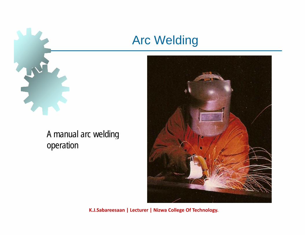
Arc WeldingArc Welding
A man al arc elding A manual arc welding operation
K.J.Sabareesaan | Lecturer | Nizwa College Of Technology.
Principal Applications of WeldingPrincipal Applications of Welding
Construction - buildings and bridgesPiping, pressure vessels, boilers, and storage tanksShipbuildingShipbuildingAircraft and aerospaceAutomotive Railroad
K.J.Sabareesaan | Lecturer | Nizwa College Of Technology.
Welder and FitterWelder and Fitter
Welder - manually controls path or placement f ldiof welding gun
Often assisted by second worker, called a fitter, who arranges the parts prior to weldingwho arranges the parts prior to welding
Welding fixtures and positioners are used to assist in this function
K.J.Sabareesaan | Lecturer | Nizwa College Of Technology.
The Safety IssueThe Safety Issue
Welding is inherently dangerous to human kworkers
High temperatures of molten metalsIn gas welding fuels (e g acetylene) are aIn gas welding, fuels (e.g., acetylene) are a fire hazard Many welding processes use electrical power, so electrical shock is a hazard
K.J.Sabareesaan | Lecturer | Nizwa College Of Technology.
Special Hazards in Arc WeldingSpecial Hazards in Arc Welding
Ultraviolet radiation emitted in arc welding is i j i t h i iinjurious to human vision
Welder must wear a special helmet with a dark viewing windowdark viewing window
Filters out dangerous radiation but welder is blind except when arc is struck
Sparks, spatters of molten metal, smoke, and fumes add to the risks
Ventilation needed to exhaust dangerousVentilation needed to exhaust dangerous fumes from fluxes and molten metals
K.J.Sabareesaan | Lecturer | Nizwa College Of Technology.
Automation in WeldingAutomation in Welding
Because of the hazards of manual welding, d t i d ti it d iand to increase productivity and improve
quality, various forms of mechanization and automation are used
Machine welding – mechanized welding under supervision and control of human operatoroperatorAutomatic welding – equipment performs welding without operator control g pRobotic welding - automatic welding implemented by industrial robot
K.J.Sabareesaan | Lecturer | Nizwa College Of Technology.
The Weld JointThe Weld Joint
The junction of the edges or surfaces of parts that h b j i d b ldihave been joined by welding Two issues about weld joints:
Types of jointsTypes of jointsTypes of welds used to join the pieces that form the joints
K.J.Sabareesaan | Lecturer | Nizwa College Of Technology.
Five Types of JointsFive Types of Joints
1. Butt joint 2. Corner joint 3. Lap joint 4 T j i t4. Tee joint 5. Edge joint
K.J.Sabareesaan | Lecturer | Nizwa College Of Technology.
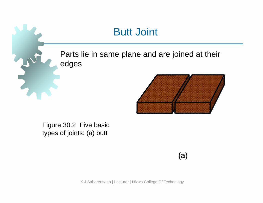
Butt Joint
Parts lie in same plane and are joined at their edgesedges
Figure 30.2 Five basic types of joints: (a) butt
K.J.Sabareesaan | Lecturer | Nizwa College Of Technology.
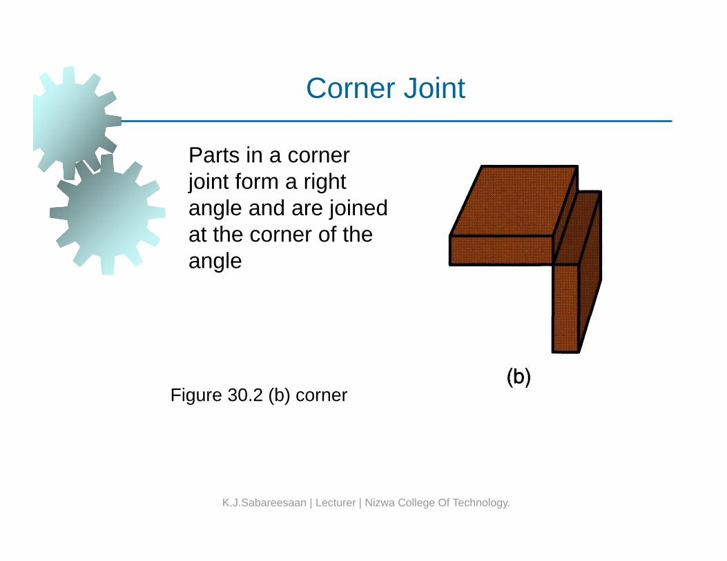
Corner Joint
Parts in a corner j i t f i htjoint form a right angle and are joined at the corner of the angle
Figure 30.2 (b) corner
K.J.Sabareesaan | Lecturer | Nizwa College Of Technology.
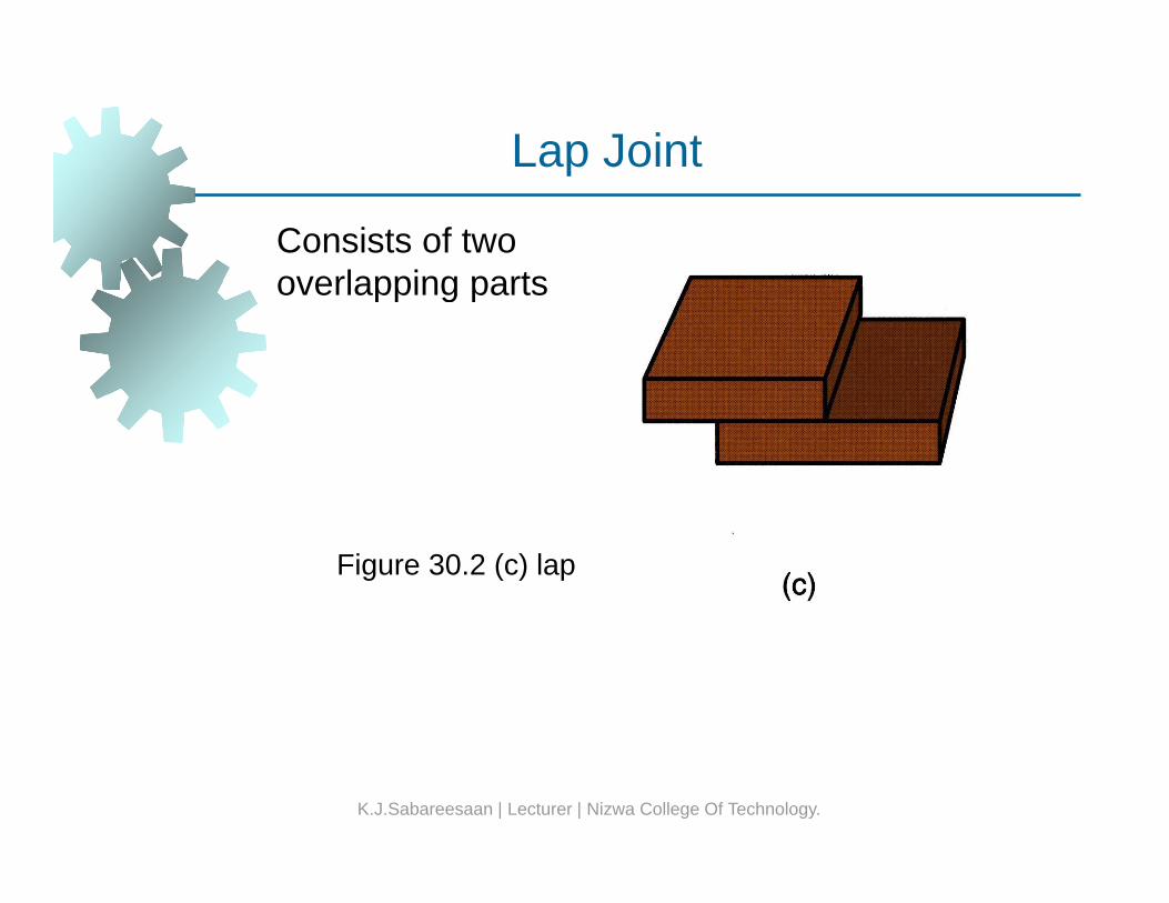
Lap Joint
Consists of two overlapping parts
ap Jo
overlapping parts
Figure 30.2 (c) lap
K.J.Sabareesaan | Lecturer | Nizwa College Of Technology.
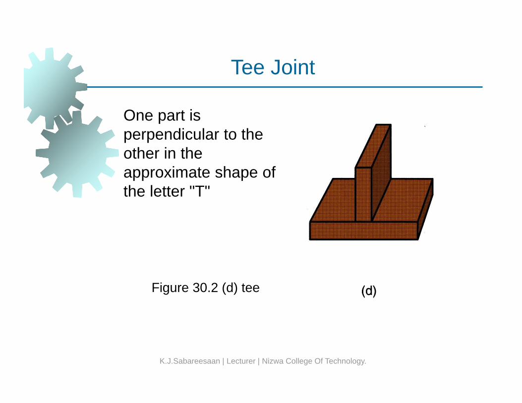
Tee Joint
One part is
ee Jo
perpendicular to the other in the approximate shape ofapproximate shape of the letter "T"
Figure 30.2 (d) tee
K.J.Sabareesaan | Lecturer | Nizwa College Of Technology.
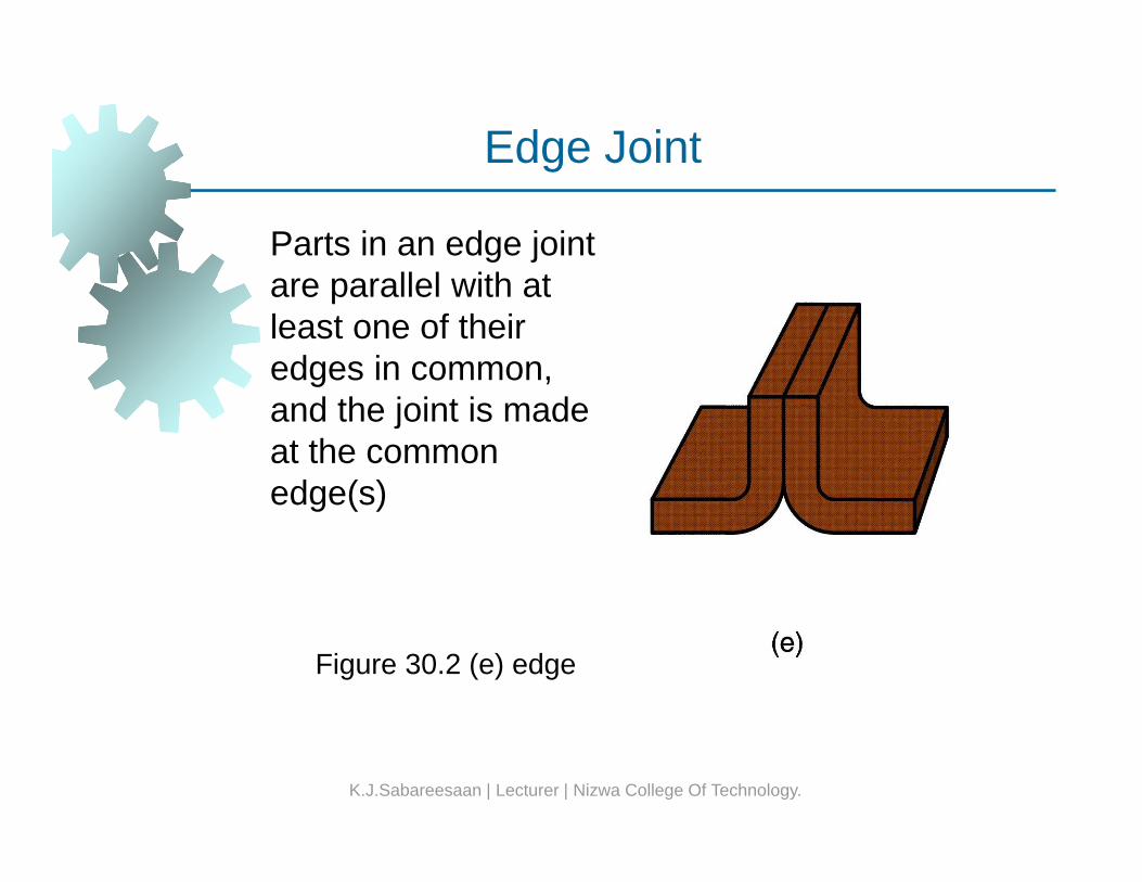
Edge Joint
Parts in an edge joint ll l ith t
dge Jo
are parallel with at least one of their edges in common, gand the joint is made at the common edge(s)edge(s)
Figure 30.2 (e) edge
K.J.Sabareesaan | Lecturer | Nizwa College Of Technology.
Types of WeldsTypes of Welds
Each of the preceding joints can be made by ldiwelding
Other joining processes can also be used for some of the joint typessome of the joint types There is a difference between joint type and the way it is welded - the weld type
K.J.Sabareesaan | Lecturer | Nizwa College Of Technology.
Fillet WeldFillet Weld
Used to fill in the edges of plates created by l d t j i tcorner, lap, and tee joints
Filler metal used to provide cross section in approximate shape of a right triangleapproximate shape of a right triangle Most common weld type in arc and oxyfuel weldingRequires minimum edge preparation
K.J.Sabareesaan | Lecturer | Nizwa College Of Technology.
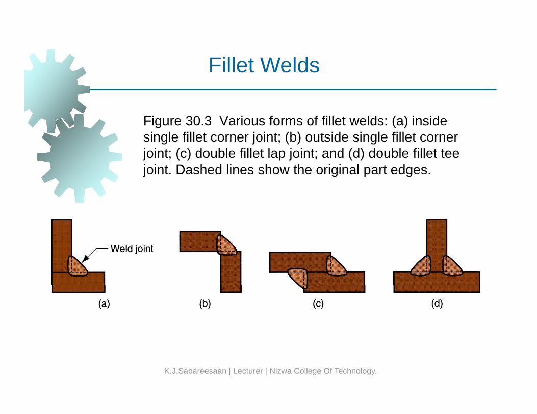
Fillet Welds
Figure 30.3 Various forms of fillet welds: (a) inside single fillet corner joint; (b) outside single fillet corner joint; (c) double fillet lap joint; and (d) double fillet tee joint. Dashed lines show the original part edges.
K.J.Sabareesaan | Lecturer | Nizwa College Of Technology.
Groove WeldsGroove Welds
Usually requires part edges to be shaped into a t f ilit t ld t tigroove to facilitate weld penetration
Edge preparation increases cost of parts fabricationfabricationGrooved shapes include square, bevel, V, U, and J, in single or double sidesMost closely associated with butt joints
K.J.Sabareesaan | Lecturer | Nizwa College Of Technology.
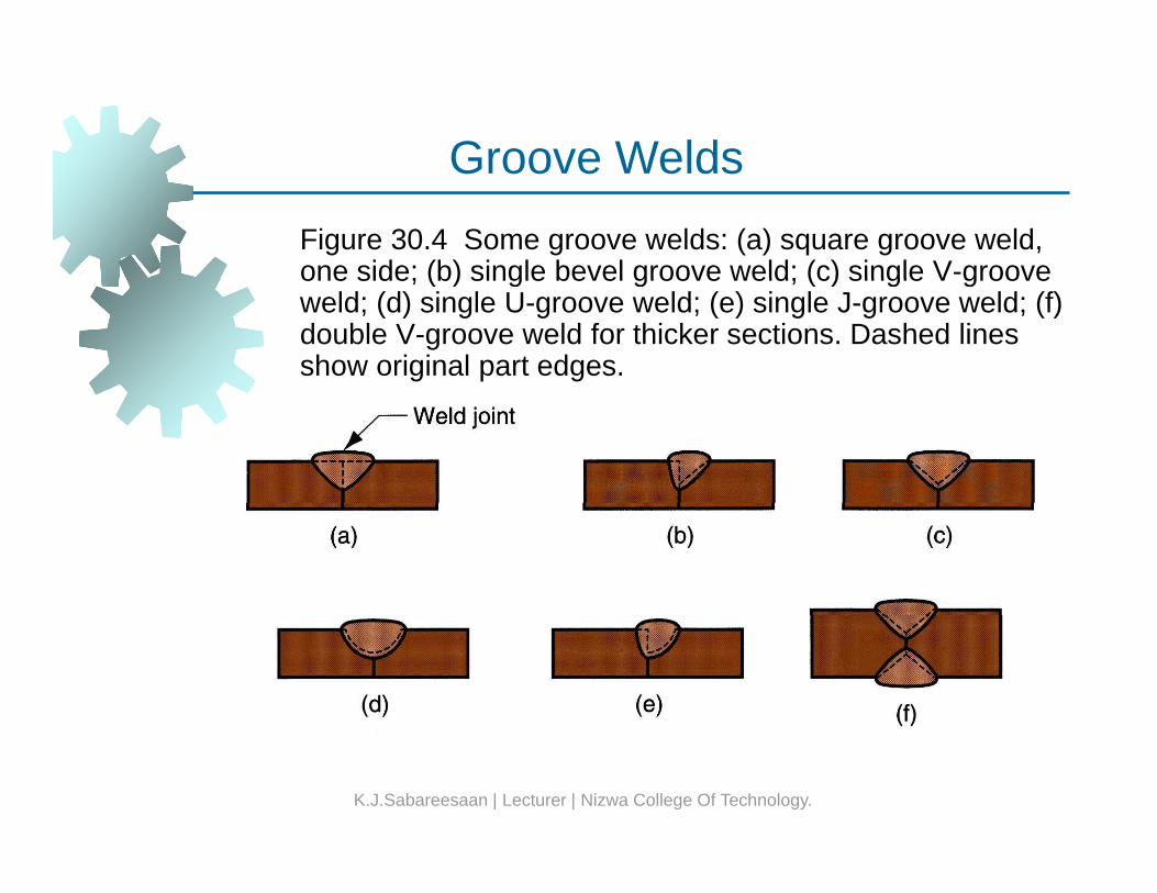
Groove WeldsFigure 30.4 Some groove welds: (a) square groove weld, one side; (b) single bevel groove weld; (c) single V-groove
Groove Welds
one side; (b) single bevel groove weld; (c) single V groove weld; (d) single U-groove weld; (e) single J-groove weld; (f) double V-groove weld for thicker sections. Dashed lines show original part edges.
K.J.Sabareesaan | Lecturer | Nizwa College Of Technology.
Spot Weld
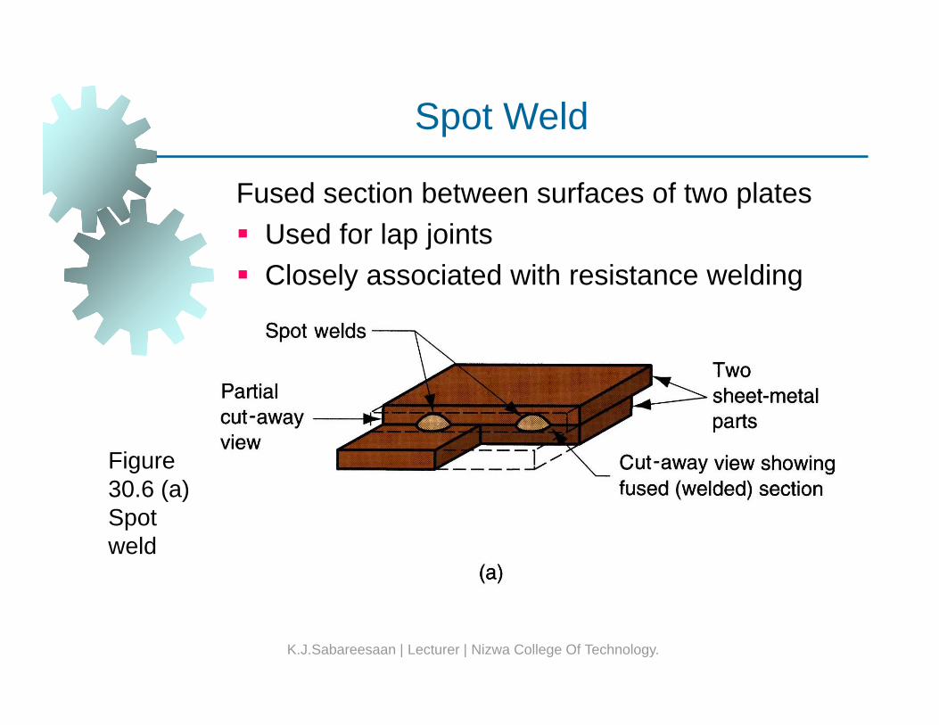
Fused section between surfaces of two plates U d f l j i t
p
Used for lap joints Closely associated with resistance welding
Figure 30.6 (a) ( )Spot weld
K.J.Sabareesaan | Lecturer | Nizwa College Of Technology.
Physics of WeldingPhysics of Welding
Fusion is most common means of achieving l i ldicoalescence in welding
To accomplish fusion, a source of high density heat energy must be supplied to the fayingheat energy must be supplied to the faying surfaces, so the resulting temperatures cause localized melting of base metals (and filler metal if used)metal, if used)For metallurgical reasons, it is desirable to melt the metal with minimum energy but high heat gy gdensities
K.J.Sabareesaan | Lecturer | Nizwa College Of Technology.
Power DensityPower Density
Power transferred to work per unit surface area, W/ 2 (Bt / i 2)W/mm2 (Btu/sec-in2)If power density is too low, heat is conducted into work, so melting never occursinto work, so melting never occurs If power density too high, localized temperatures vaporize metal in affected region There is a practical range of values for heat density within which welding can be performed
K.J.Sabareesaan | Lecturer | Nizwa College Of Technology.
Comparisons Among Welding ProcessesComparisons Among Welding Processes
Oxyfuel gas welding (OFW) develops large t f h t b t h t d it i l ti lamounts of heat, but heat density is relatively
low because heat is spread over a large areaOxyacetylene gas, the hottest of the OFWOxyacetylene gas, the hottest of the OFW fuels, burns at a top temperature of around 3500°C (6300°F)
A ldi d hi hArc welding produces high energy over a smaller area, resulting in local temperatures of 5500° to 6600°C (10,000° to 12,000°F)( , , )
K.J.Sabareesaan | Lecturer | Nizwa College Of Technology.
Power Densities for Welding ProcessesPower Densities for Welding Processes
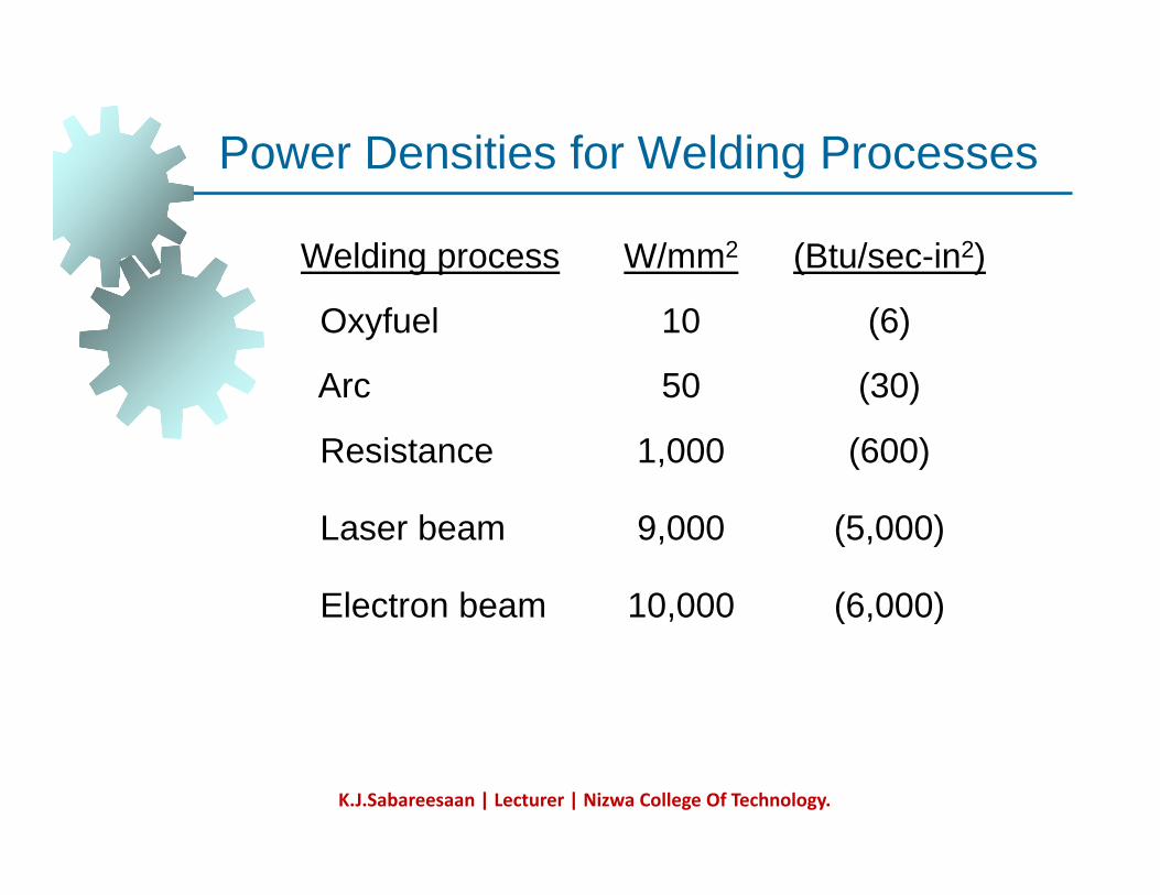
Welding process W/mm2 (Btu/sec-in2)
Oxyfuel 10 (6)
Arc 50 (30)Arc 50 (30)
Resistance 1,000 (600)
Laser beam 9,000 (5,000)
Electron beam 10,000 (6,000)Electron beam 10,000 (6,000)
K.J.Sabareesaan | Lecturer | Nizwa College Of Technology.
Power DensityPower Density
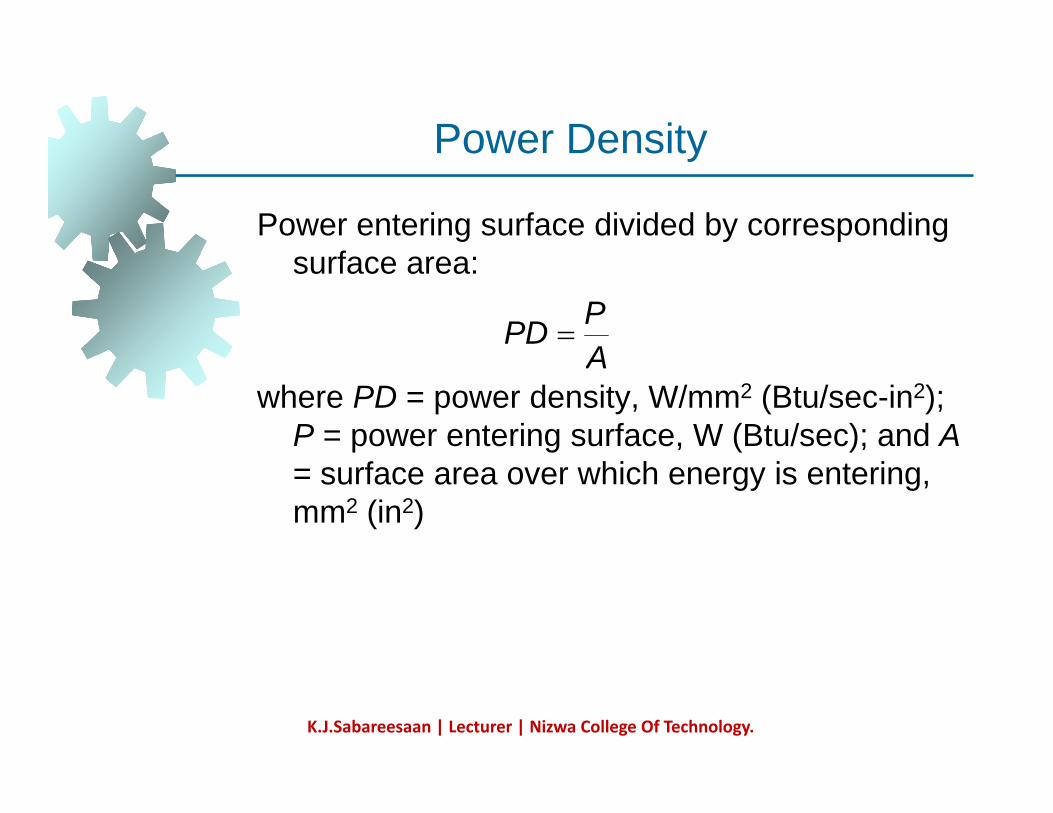
Power entering surface divided by corresponding fsurface area:
APPD =
where PD = power density, W/mm2 (Btu/sec-in2); P = power entering surface, W (Btu/sec); and A
A
= surface area over which energy is entering, mm2 (in2)
K.J.Sabareesaan | Lecturer | Nizwa College Of Technology.
Unit Energy for Melting
Quantity of heat required to melt a unit volume Q y qof metal Symbolized Um
It is the sum of: Heat to raise temperature of solid metal to melting pointto melting point
Depends on volumetric specific heatHeat to transform metal from solid to liquid phase at melting point
Depends on heat of fusion
K.J.Sabareesaan | Lecturer | Nizwa College Of Technology.
Heat Transfer Mechanisms in WeldingHeat Transfer Mechanisms in Welding
Not all of the input energy is used to melt the ld t lweld metal
1. Heat transfer efficiency f1 - actual heat received by workpiece divided by total heatreceived by workpiece divided by total heat generated at source
2. Melting efficiency f2 - proportion of heat i d k f d f l ireceived at work surface used for melting;
the rest is conducted into work metal
K.J.Sabareesaan | Lecturer | Nizwa College Of Technology.
Heat Available for WeldingHeat Available for Welding
Hw = f1 f2 Hw 1 2
where Hw = net heat available for welding; f1 = heat transfer efficiency; f2 = melting efficiency;heat transfer efficiency; f2 melting efficiency; and H = total heat generated by welding process
K.J.Sabareesaan | Lecturer | Nizwa College Of Technology.
Heat Transfer Efficiency f1Heat Transfer Efficiency f1
Proportion of heat received at work surface l ti t t t l h t t d trelative to total heat generated at source
Depends on welding process and capacity to convert power source (e.g., electrical energy)convert power source (e.g., electrical energy) into usable heat at work surface
Oxyfuel gas welding processes are l i l i ffi irelatively inefficient
Arc welding processes are relatively efficient
K.J.Sabareesaan | Lecturer | Nizwa College Of Technology.
Melting Efficiency f2Melting Efficiency f2
Proportion of heat received at work surface used f lti th t i d t d i t th kfor melting; the rest is conducted into the workDepends on welding process but also influenced by thermal properties of metal, jointinfluenced by thermal properties of metal, joint configuration, and work thickness
Metals with high thermal conductivity, such l i d blas aluminum and copper, present a problem
in welding because of the rapid dissipation of heat away from the heat contact area y
K.J.Sabareesaan | Lecturer | Nizwa College Of Technology.
Energy Balance EquationEnergy Balance Equation
Net heat energy into welding operation equals h t i d t lt th l fheat energy required to melt the volume of metal welded
Hw = Um VHw Um V
where Hw = net heat energy delivered to operation J (Btu); Um = unit energy required tooperation, J (Btu); Um unit energy required to melt the metal, J/mm3 (Btu/in3); and V = volume of metal melted, mm3 (in3)
K.J.Sabareesaan | Lecturer | Nizwa College Of Technology.
Typical Fusion Welded Joint
Fi 30 8 C ti f t i l f i ld d
yp ca us o e ded Jo
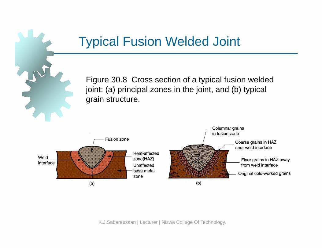
Figure 30.8 Cross section of a typical fusion welded joint: (a) principal zones in the joint, and (b) typical grain structure.
K.J.Sabareesaan | Lecturer | Nizwa College Of Technology.
Features of Fusion Welded JointFeatures of Fusion Welded Joint
Typical fusion weld joint in which filler metal has b dd d i t fbeen added consists of: Fusion zoneWeld interfaceWeld interfaceHeat affected zone (HAZ) Unaffected base metal zone
K.J.Sabareesaan | Lecturer | Nizwa College Of Technology.
Heat Affected ZoneHeat Affected Zone
Metal has experienced temperatures below lti i t b t hi h h tmelting point, but high enough to cause
microstructural changes in the solid metalChemical composition same as base metal, butChemical composition same as base metal, but this region has been heat treated so that its properties and structure have been altered
Eff h i l i i HAZ iEffect on mechanical properties in HAZ is usually negative, and it is here that welding failures often occur
K.J.Sabareesaan | Lecturer | Nizwa College Of Technology.
WELDING PROCESSESWELDING PROCESSES
1. Arc Welding2. Resistance Welding3. Oxyfuel Gas Welding4 Oth F i W ldi P4. Other Fusion Welding Processes5. Solid State Welding6 Weld Quality6. Weld Quality7. Weldability8. Design Considerations in Weldingg g
K.J.Sabareesaan | Lecturer | Nizwa College Of Technology.
Two Categories of Welding ProcessesTwo Categories of Welding Processes
Fusion welding - coalescence is accomplished b lti th t t t b j i d iby melting the two parts to be joined, in some cases adding filler metal to the joint
Examples: arc welding, resistance spotExamples: arc welding, resistance spot welding, oxyfuel gas welding
Solid state welding - heat and/or pressure are d hi l b l i fused to achieve coalescence, but no melting of
base metals occurs and no filler metal is added Examples: forge welding diffusion weldingExamples: forge welding, diffusion welding, friction welding
K.J.Sabareesaan | Lecturer | Nizwa College Of Technology.
Arc Welding (AW)Arc Welding (AW)
A fusion welding process in which coalescence of th t l i hi d b th h t fthe metals is achieved by the heat from an electric arc between an electrode and the workElectric energy from the arc producesElectric energy from the arc produces temperatures ~ 10,000 F (5500 C), hot enough to melt any metalM AW dd fill l iMost AW processes add filler metal to increase volume and strength of weld joint
K.J.Sabareesaan | Lecturer | Nizwa College Of Technology.
What is an Electric Arc?What is an Electric Arc?
An electric arc is a discharge of electric current i i itacross a gap in a circuit
It is sustained by an ionized column of gas (plasma) through which the current flows(plasma) through which the current flows To initiate the arc in AW, electrode is brought into contact with work and then quickly
d f i b h diseparated from it by a short distance
K.J.Sabareesaan | Lecturer | Nizwa College Of Technology.
Arc Welding
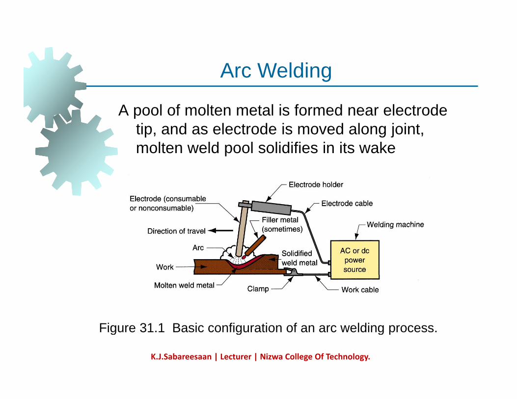
A pool of molten metal is formed near electrode ti d l t d i d l j i t
Arc Welding
tip, and as electrode is moved along joint, molten weld pool solidifies in its wake
Figure 31 1 Basic configuration of an arc welding processFigure 31.1 Basic configuration of an arc welding process.
K.J.Sabareesaan | Lecturer | Nizwa College Of Technology.
Manual Arc Welding and Arc TimeManual Arc Welding and Arc Time
Problems with manual welding:Weld joint qualityProductivity
A Ti (ti i ) di id d b (hArc Time = (time arc is on) divided by (hours worked)
Also called “arc-on time”Manual welding arc time = 20%Machine welding arc time ~ 50%
K.J.Sabareesaan | Lecturer | Nizwa College Of Technology.
Two Basic Types of AW ElectrodesTwo Basic Types of AW Electrodes
Consumable – consumed during welding process
Source of filler metal in arc weldingNonconsumable not consumed duringNonconsumable – not consumed during welding process
Filler metal must be added separately
K.J.Sabareesaan | Lecturer | Nizwa College Of Technology.
Consumable ElectrodesConsumable Electrodes
Forms of consumable electrodesWelding rods (a.k.a. sticks) are 9 to 18 inches and 3/8 inch or less in diameter and must be changed frequentlymust be changed frequentlyWeld wire can be continuously fed from spools with long lengths of wire, avoiding f i ifrequent interruptions
In both rod and wire forms, electrode is consumed by arc and added to weld joint asconsumed by arc and added to weld joint as filler metal
K.J.Sabareesaan | Lecturer | Nizwa College Of Technology.
Nonconsumable ElectrodesNonconsumable Electrodes
Made of tungsten which resists melting Gradually depleted during welding (vaporization is principal mechanism) Any filler metal must be supplied by a separateAny filler metal must be supplied by a separate wire fed into weld pool
K.J.Sabareesaan | Lecturer | Nizwa College Of Technology.
Arc ShieldingArc Shielding
At high temperatures in AW, metals are h i ll ti t it dchemically reactive to oxygen, nitrogen, and
hydrogen in air Mechanical properties of joint can beMechanical properties of joint can be seriously degraded by these reactions To protect operation, arc must be shielded f di i i AWfrom surrounding air in AW processes
Arc shielding is accomplished by: Shielding gases e g argon helium COShielding gases, e.g., argon, helium, CO2
Flux
K.J.Sabareesaan | Lecturer | Nizwa College Of Technology.
FluxFlux
A substance that prevents formation of oxides d th t i t i ldiand other contaminants in welding, or
dissolves them and facilitates removalProvides protective atmosphere for weldingProvides protective atmosphere for weldingStabilizes arcReduces spattering
K.J.Sabareesaan | Lecturer | Nizwa College Of Technology.
Various Flux Application MethodsVarious Flux Application Methods
Pouring granular flux onto welding operationStick electrode coated with flux material that melts during welding to cover operationTubular electrodes in which flux is contained inTubular electrodes in which flux is contained in the core and released as electrode is consumed
K.J.Sabareesaan | Lecturer | Nizwa College Of Technology.
Power Source in Arc WeldingPower Source in Arc Welding
Direct current (DC) vs. Alternating current (AC) AC machines less expensive to purchase and operate, but generally restricted to ferrous metalsferrous metalsDC equipment can be used on all metals and is generally noted for better arc control
K.J.Sabareesaan | Lecturer | Nizwa College Of Technology.
Consumable Electrode AW ProcessesConsumable Electrode AW Processes
Shielded Metal Arc WeldingGas Metal Arc WeldingFlux-Cored Arc WeldingEl t W ldiElectrogas WeldingSubmerged Arc Welding
K.J.Sabareesaan | Lecturer | Nizwa College Of Technology.
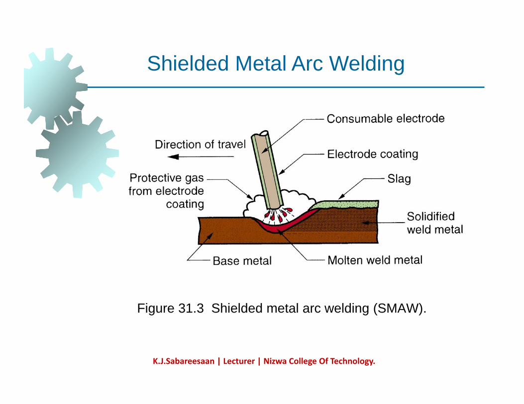
Shielded Metal Arc Welding (SMAW)Shielded Metal Arc Welding (SMAW)
Uses a consumable electrode consisting of a filler t l d t d ith h i l th t idmetal rod coated with chemicals that provide
flux and shielding Sometimes called "stick welding"Sometimes called stick weldingPower supply, connecting cables, and electrode holder available for a few thousand d lldollars
K.J.Sabareesaan | Lecturer | Nizwa College Of Technology.
Shielded Metal Arc Weldingg
Figure 31.3 Shielded metal arc welding (SMAW).
K.J.Sabareesaan | Lecturer | Nizwa College Of Technology.
Welding Stick in SMAWWelding Stick in SMAW
Composition of filler metal usually close to base metalbase metalCoating: powdered cellulose mixed with oxides, carbonates, and other ingredients, gheld together by a silicate binder Welding stick is clamped in electrode holder connected to power sourceconnected to power sourceDisadvantages of stick welding:
Sticks must be periodically changedSticks must be periodically changedHigh current levels may melt coating prematurely
K.J.Sabareesaan | Lecturer | Nizwa College Of Technology.
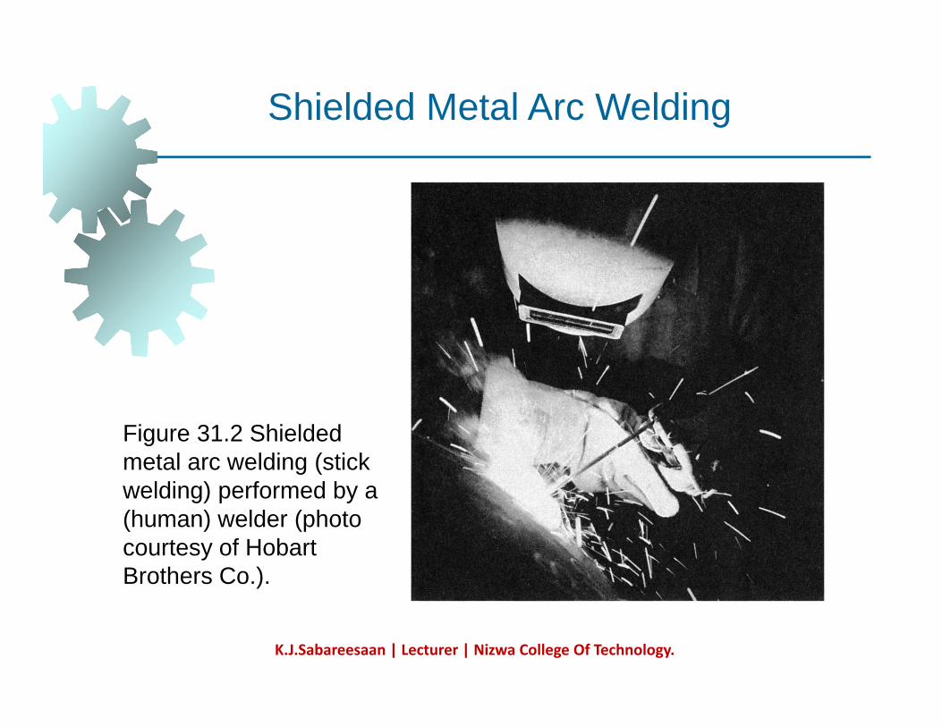
Shielded Metal Arc Welding
Figure 31.2 Shielded metal arc welding (stick welding) performed by a g) p y(human) welder (photo courtesy of Hobart Brothers Co.).
K.J.Sabareesaan | Lecturer | Nizwa College Of Technology.
SMAW ApplicationsSMAW Applications
Used for steels, stainless steels, cast i d t i f llirons, and certain nonferrous alloys Not used or rarely used for aluminum and its alloys, copper alloys, andand its alloys, copper alloys, and titanium
K.J.Sabareesaan | Lecturer | Nizwa College Of Technology.
Arc Welding Design GuidelinesArc Welding Design Guidelines
Good fit-up of parts - to maintain di i l t l d i i i di t tidimensional control and minimize distortion
Machining is sometimes required to achieve satisfactory fit-upachieve satisfactory fit up
Assembly must allow access for welding gun to reach welding area Design of assembly should allow flat welding to be performed as much as possible since this is fastest and mostpossible, since this is fastest and most convenient welding position
K.J.Sabareesaan | Lecturer | Nizwa College Of Technology.
Arc Welding Positions
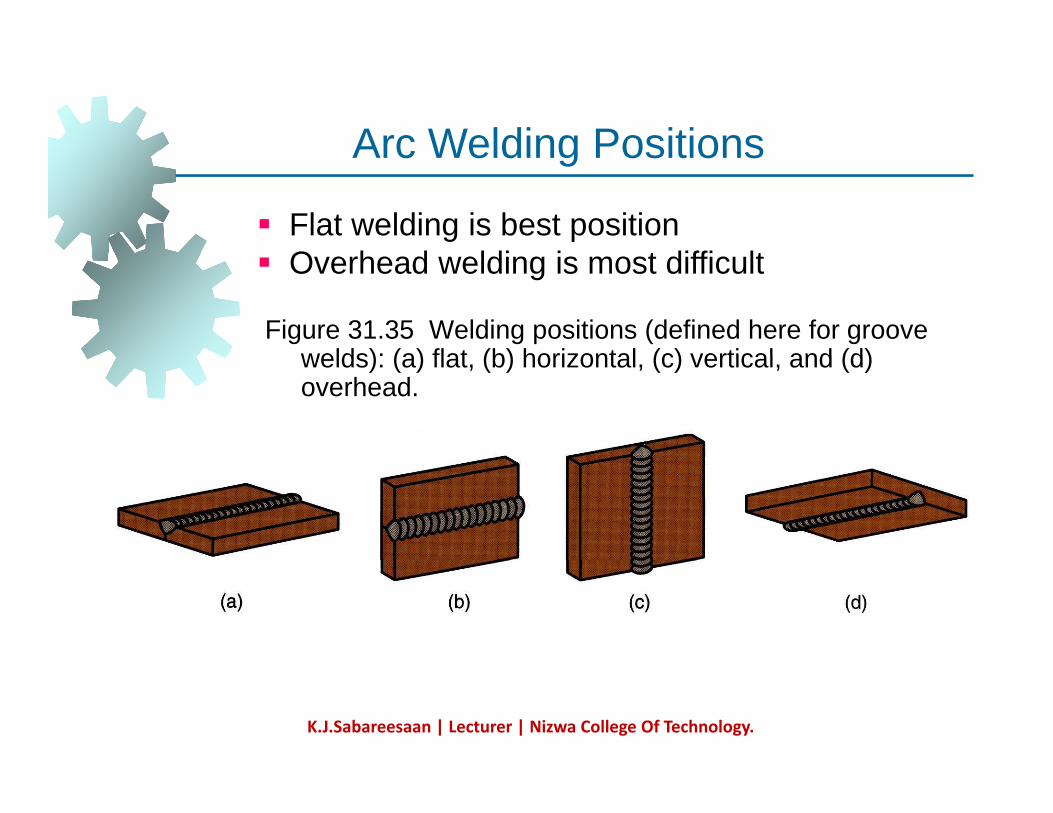
Flat welding is best positionO h d ldi i t diffi lt
Arc Welding Positions
Figure 31.35 Welding positions (defined here for groove welds): (a) flat (b) horizontal (c) vertical and (d)
Overhead welding is most difficult
welds): (a) flat, (b) horizontal, (c) vertical, and (d) overhead.
K.J.Sabareesaan | Lecturer | Nizwa College Of Technology.
Design Guidelines - RSWDesign Guidelines RSW
Low-carbon sheet steel up to 0.125 (3.2 mm) is id l t l f RSWideal metal for RSW How additional strength and stiffness can be obtained in large flat sheet metal componentsobtained in large flat sheet metal components
Spot welding reinforcing parts into them Forming flanges and embossments
Spot welded assembly must provide access for electrodes to reach welding area S ffi i t l f h t t l t i dSufficient overlap of sheet metal parts required for electrode tip to make proper contact
K.J.Sabareesaan | Lecturer | Nizwa College Of Technology.
Oxy fuel Gas Welding (OFW)
K.J.Sabareesaan | Lecturer | Nizwa College Of Technology.
Oxyfuel Gas Welding (OFW)Oxyfuel Gas Welding (OFW)
Group of fusion welding operations that burn i f l i d ithvarious fuels mixed with oxygen
OFW employs several types of gases, which is the primary distinction among the members ofthe primary distinction among the members of this group Oxyfuel gas is also used in flame cutting
h d l l dtorches to cut and separate metal plates and other partsMost important OFW process is oxyacetyleneMost important OFW process is oxyacetylene welding
K.J.Sabareesaan | Lecturer | Nizwa College Of Technology.
Oxyacetylene Welding (OAW)Oxyacetylene Welding (OAW)
Fusion welding performed by a high temperature fl f b ti f t l dflame from combustion of acetylene and oxygen Flame is directed by a welding torchFlame is directed by a welding torchFiller metal is sometimes added
Composition must be similar to base metalFiller rod often coated with flux to clean surfaces and prevent oxidation
K.J.Sabareesaan | Lecturer | Nizwa College Of Technology.
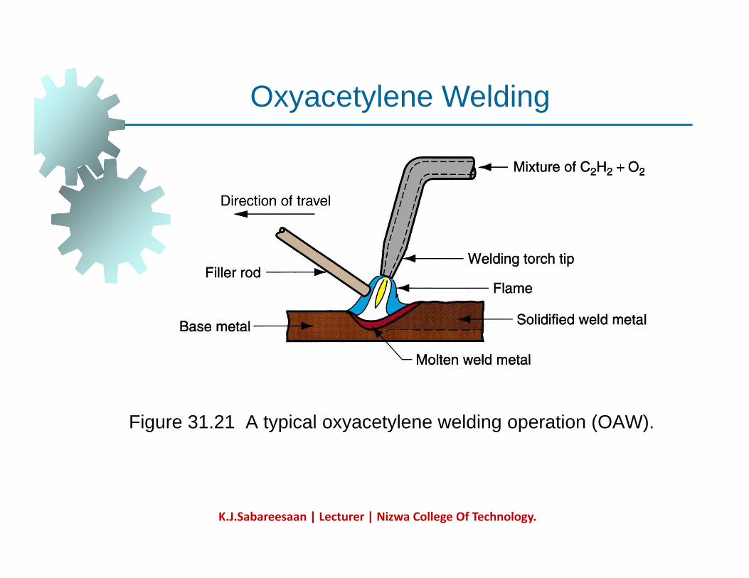
Oxyacetylene WeldingO yace y e e e d g
Figure 31.21 A typical oxyacetylene welding operation (OAW).
K.J.Sabareesaan | Lecturer | Nizwa College Of Technology.
Acetylene (C2H2)Acetylene (C2H2)
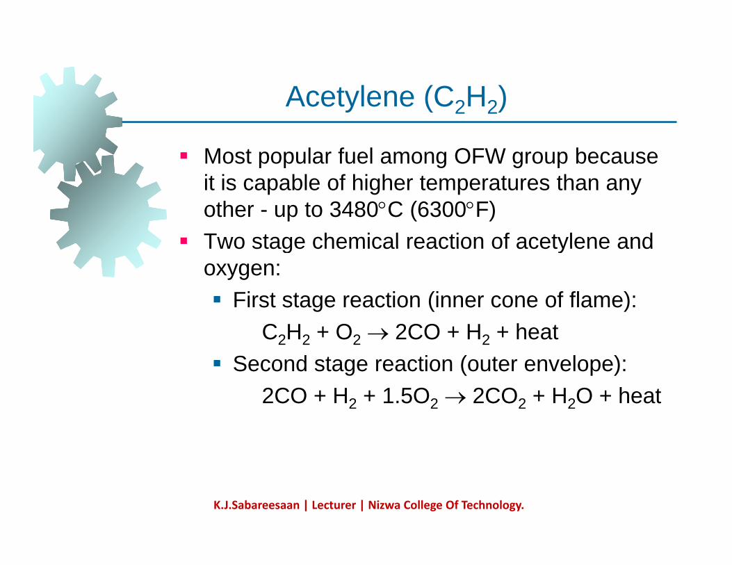
Most popular fuel among OFW group because it i bl f hi h t t thit is capable of higher temperatures than any other - up to 3480°C (6300°F) Two stage chemical reaction of acetylene andTwo stage chemical reaction of acetylene and oxygen:
First stage reaction (inner cone of flame): C2H2 + O2 → 2CO + H2 + heat
Second stage reaction (outer envelope): 2CO H 1 5O 2CO H O h t2CO + H2 + 1.5O2 → 2CO2 + H2O + heat
K.J.Sabareesaan | Lecturer | Nizwa College Of Technology.
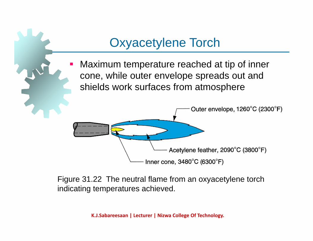
Oxyacetylene TorchMaximum temperature reached at tip of inner cone while outer envelope spreads out and
Oxyacetylene Torch
cone, while outer envelope spreads out and shields work surfaces from atmosphere
Figure 31.22 The neutral flame from an oxyacetylene torch indicating temperatures achieved.
K.J.Sabareesaan | Lecturer | Nizwa College Of Technology.
Safety Issue in OAWSafety Issue in OAW
Together, acetylene and oxygen are highly fl blflammableC2H2 is colorless and odorless
It is therefore processed to haveIt is therefore processed to have characteristic garlic odor
K.J.Sabareesaan | Lecturer | Nizwa College Of Technology.
OAW Safety IssueOAW Safety Issue
C2H2 is physically unstable at pressures much b 15 lb/i 2 ( b t 1 t )above 15 lb/in2 (about 1 atm)
Storage cylinders are packed with porous filler material (such as asbestos) saturatedfiller material (such as asbestos) saturated with acetone (CH3COCH3)Acetone dissolves about 25 times its own
l f lvolume of acetyleneDifferent screw threads are standard on the C2H2and O2 cylinders and hoses to avoid accidentaland O2 cylinders and hoses to avoid accidental connection of wrong gases
K.J.Sabareesaan | Lecturer | Nizwa College Of Technology.
Alternative Gases for OFWAlternative Gases for OFW
Methylacetylene-Propadiene (MAPP)HydrogenPropylenePPropaneNatural Gas
K.J.Sabareesaan | Lecturer | Nizwa College Of Technology.
Gas Metal Arc Welding (GMAW)(GMAW)
Uses a consumable bare metal wire as electrode and shielding accomplished byelectrode and shielding accomplished by flooding arc with a gasWire is fed continuously and automatically y yfrom a spool through the welding gun Shielding gases include inert gases such as argon and helium for aluminum welding andargon and helium for aluminum welding, and active gases such as CO2 for steel welding Bare electrode wire plus shielding gases p g geliminate slag on weld bead - no need for manual grinding and cleaning of slag
K.J.Sabareesaan | Lecturer | Nizwa College Of Technology.
Gas Metal Arc Weldingg
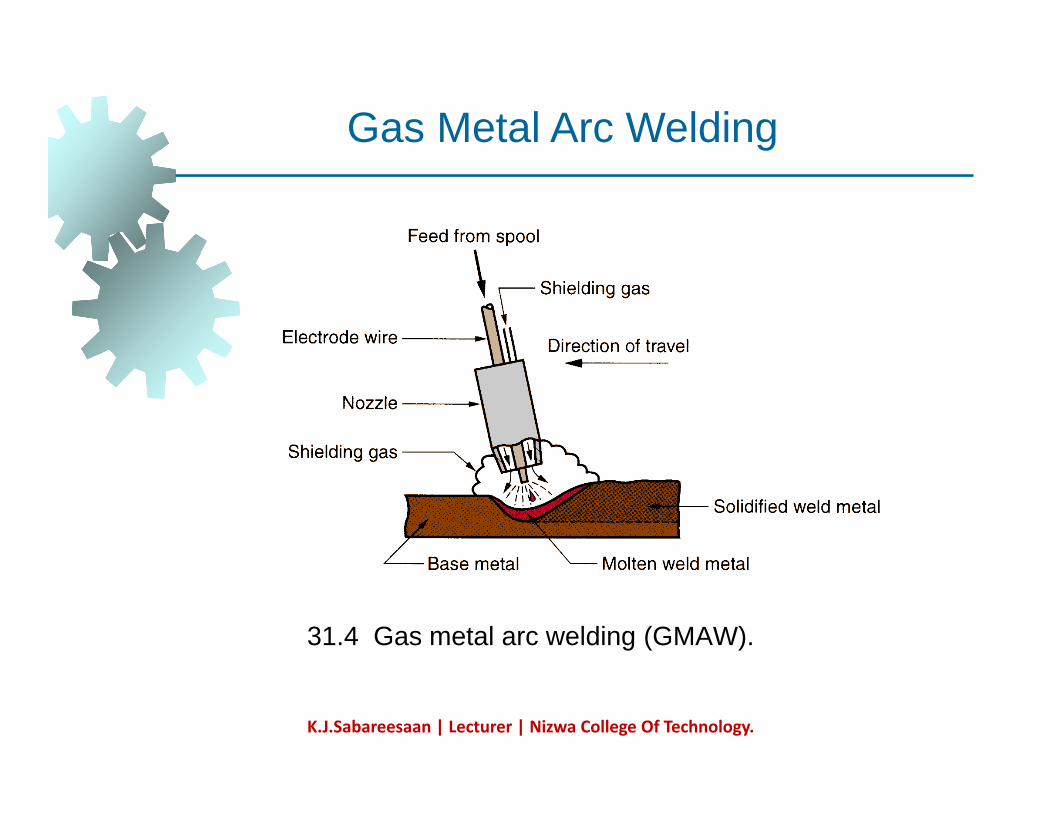
31.4 Gas metal arc welding (GMAW).
K.J.Sabareesaan | Lecturer | Nizwa College Of Technology.
GMAW Advantages over SMAWGMAW Advantages over SMAW
Better arc time because of continuous wire l t delectrode
Sticks must be periodically changed in SMAWSMAW
Better use of electrode filler metal than SMAWEnd of stick cannot be used in SMAW
Higher deposition ratesEliminates problem of slag removalCan be readily automated
K.J.Sabareesaan | Lecturer | Nizwa College Of Technology.
Nonconsumable Electrode ProcessesNonconsumable Electrode Processes
Gas Tungsten Arc WeldingPlasma Arc WeldingCarbon Arc Welding St d W ldiStud Welding
K.J.Sabareesaan | Lecturer | Nizwa College Of Technology.
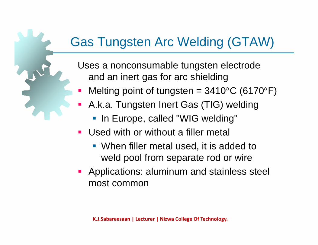
Gas Tungsten Arc Welding (GTAW)Gas Tungsten Arc Welding (GTAW)
Uses a nonconsumable tungsten electrode and an inert gas for arc shieldingand an inert gas for arc shielding Melting point of tungsten = 3410°C (6170°F)A.k.a. Tungsten Inert Gas (TIG) weldingA.k.a. Tungsten Inert Gas (TIG) welding
In Europe, called "WIG welding" Used with or without a filler metal
When filler metal used, it is added to weld pool from separate rod or wire
A li ti l i d t i l t lApplications: aluminum and stainless steel most common
K.J.Sabareesaan | Lecturer | Nizwa College Of Technology.
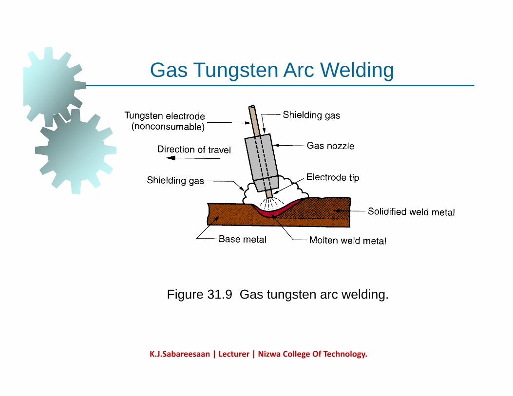
Gas Tungsten Arc WeldingGas Tungsten Arc Welding
Figure 31.9 Gas tungsten arc welding.
K.J.Sabareesaan | Lecturer | Nizwa College Of Technology.
Advantages / Disadvantages of GTAWAdvantages / Disadvantages of GTAW
Advantages:High quality welds for suitable applicationsNo spatter because no filler metal through arcarcLittle or no post-weld cleaning because no fluxflux
Disadvantages:Generally slower and more costly than consumable electrode AW processes
K.J.Sabareesaan | Lecturer | Nizwa College Of Technology.
Plasma Arc Welding (PAW)Plasma Arc Welding (PAW)
Special form of GTAW in which a constricted l i di t d t ldplasma arc is directed at weld area
Tungsten electrode is contained in a nozzle that focuses a high velocity stream of inert gasthat focuses a high velocity stream of inert gas (argon) into arc region to form a high velocity, intensely hot plasma arc stream T i PAW h 28 000 CTemperatures in PAW reach 28,000°C (50,000°F), due to constriction of arc, producing a plasma jet of small diameter and p g p jvery high energy density
K.J.Sabareesaan | Lecturer | Nizwa College Of Technology.
Resistance Welding (RW)Resistance Welding (RW)
A group of fusion welding processes that use a bi ti f h t d tcombination of heat and pressure to
accomplish coalescence Heat generated by electrical resistance toHeat generated by electrical resistance to current flow at junction to be welded Principal RW process is resistance spot
ldi (RSW)welding (RSW)
K.J.Sabareesaan | Lecturer | Nizwa College Of Technology.
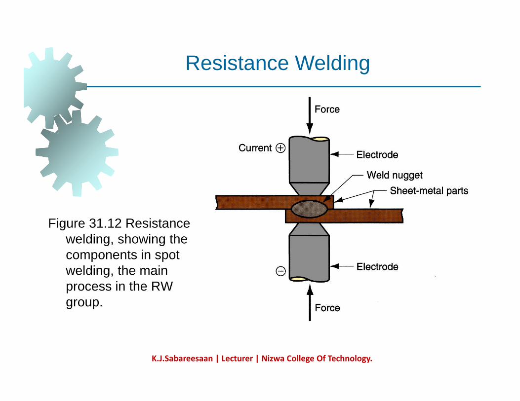
Resistance Weldingg
Figure 31 12 ResistanceFigure 31.12 Resistance welding, showing the components in spot welding, the main g,process in the RW group.
K.J.Sabareesaan | Lecturer | Nizwa College Of Technology.
Components in Resistance Spot WeldingComponents in Resistance Spot Welding
Parts to be welded (usually sheet metal)Two opposing electrodesMeans of applying pressure to squeeze parts between electrodesbetween electrodesPower supply from which a controlled current can be applied for a specified time duration
K.J.Sabareesaan | Lecturer | Nizwa College Of Technology.
Advantages / Drawbacks of RWAdvantages / Drawbacks of RW
Advantages:No filler metal requiredHigh production rates possibleL d it lf t h i ti d t tiLends itself to mechanization and automationLower operator skill level than for arc weldingGood repeatability and reliabilityGood repeatability and reliability
Disadvantages:High initial equipment costg q pLimited to lap joints for most RW processes
K.J.Sabareesaan | Lecturer | Nizwa College Of Technology.
Resistance Spot Welding (RSW)Resistance Spot Welding (RSW)
Resistance welding process in which fusion of faying surfaces of a lap joint is achieved at onefaying surfaces of a lap joint is achieved at one location by opposing electrodes Used to join sheet metal parts using a series of j p gspot welds Widely used in mass production of automobiles appliances metal furniture andautomobiles, appliances, metal furniture, and other products made of sheet metal
Typical car body has ~ 10,000 spot welds yp y , pAnnual production of automobiles in the world is measured in tens of millions of units
K.J.Sabareesaan | Lecturer | Nizwa College Of Technology.
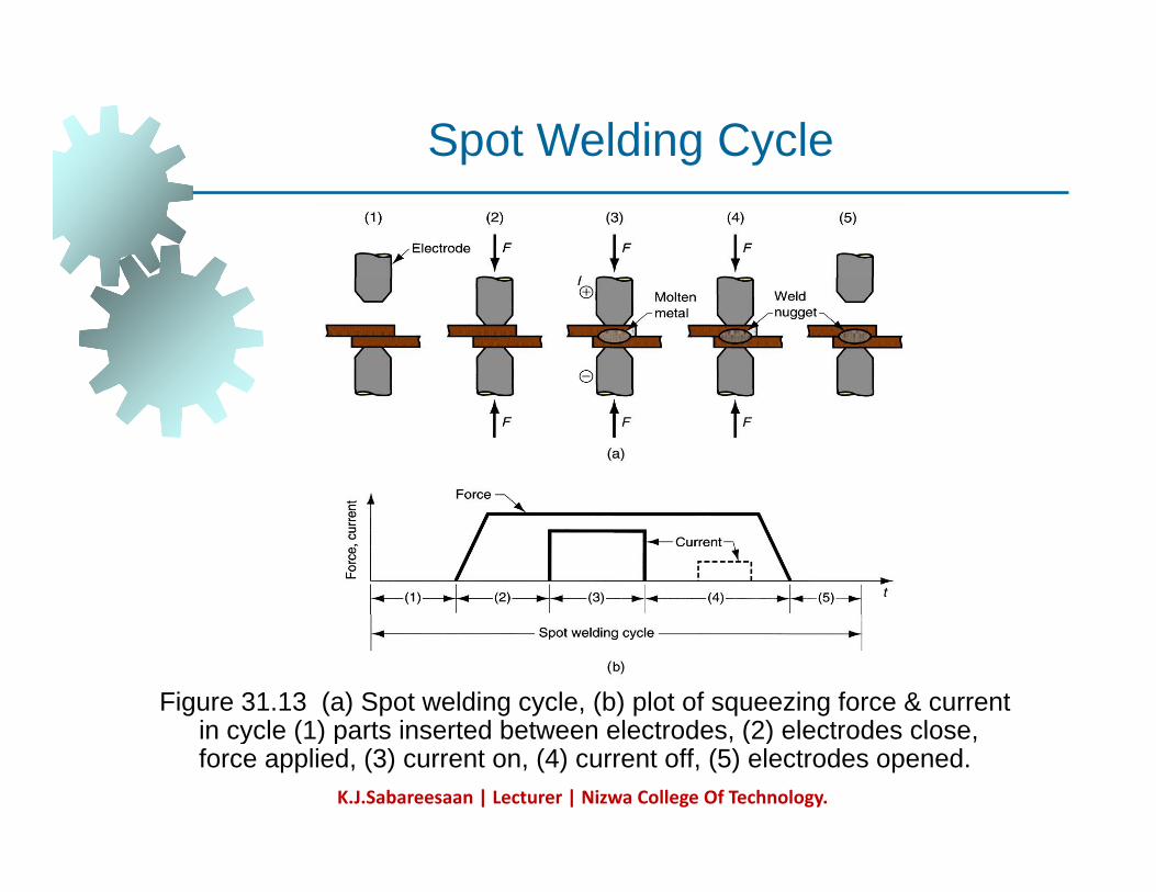
Spot Welding Cycleg y
Figure 31.13 (a) Spot welding cycle, (b) plot of squeezing force & current in cycle (1) parts inserted between electrodes (2) electrodes closein cycle (1) parts inserted between electrodes, (2) electrodes close, force applied, (3) current on, (4) current off, (5) electrodes opened.
K.J.Sabareesaan | Lecturer | Nizwa College Of Technology.
Resistance Seam Welding (RSEW)Resistance Seam Welding (RSEW)
Uses rotating wheel electrodes to produce a i f l i t ld l lseries of overlapping spot welds along lap
jointCan produce air-tight jointsCan produce air tight joints Applications:
Gasoline tanks Automobile mufflers Various other sheet metal containers
K.J.Sabareesaan | Lecturer | Nizwa College Of Technology.
Resistance Seam Weldinges s a ce Sea e d g
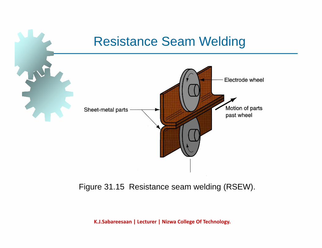
Figure 31.15 Resistance seam welding (RSEW).
K.J.Sabareesaan | Lecturer | Nizwa College Of Technology.
Other Fusion Welding ProcessesOther Fusion Welding Processes
FW processes that cannot be classified as arc, i t f l ldiresistance, or oxyfuel welding
Use unique technologies to develop heat for meltingmeltingApplications are typically unique Processes include:
Electron beam weldingLaser beam weldingElectroslag weldingThermit welding
K.J.Sabareesaan | Lecturer | Nizwa College Of Technology.
Roll Welding (ROW)Roll Welding (ROW)
SSW process in which pressure sufficient to l i li d b fcause coalescence is applied by means of
rolls, either with or without external heat Variation of either forge welding or coldVariation of either forge welding or cold welding, depending on whether heating of workparts is done prior to process
If l h ll d ld ll ldiIf no external heat, called cold roll weldingIf heat is supplied, hot roll welding
K.J.Sabareesaan | Lecturer | Nizwa College Of Technology.
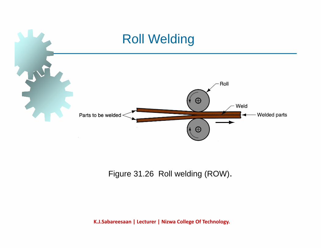
Roll Weldingg
Fi 31 26 R ll ldi (ROW)Figure 31.26 Roll welding (ROW).
K.J.Sabareesaan | Lecturer | Nizwa College Of Technology.
Roll Welding ApplicationsRoll Welding Applications
Cladding stainless steel to mild or low alloy t l f i i tsteel for corrosion resistance
Bimetallic strips for measuring temperature"Sandwich" coins for U S mintSandwich coins for U.S mint
K.J.Sabareesaan | Lecturer | Nizwa College Of Technology.
Diffusion Welding (DFW)Diffusion Welding (DFW)
SSW process uses heat and pressure, usually in t ll d t h ith ffi i t ti fa controlled atmosphere, with sufficient time for
diffusion and coalescence to occur Temperatures ≤ 0.5 TmTemperatures ≤ 0.5 Tm
Plastic deformation at surfaces is minimal Primary coalescence mechanism is solid state diffusionLimitation: time required for diffusion can range from seconds to hoursfrom seconds to hours
K.J.Sabareesaan | Lecturer | Nizwa College Of Technology.
DFW ApplicationsDFW Applications
Joining of high-strength and refractory metals i d l i d t iin aerospace and nuclear industriesCan be used to join either similar and dissimilar metalsmetalsFor joining dissimilar metals, a filler layer of different metal is often sandwiched between b l diff ibase metals to promote diffusion
K.J.Sabareesaan | Lecturer | Nizwa College Of Technology.
Explosive Welding
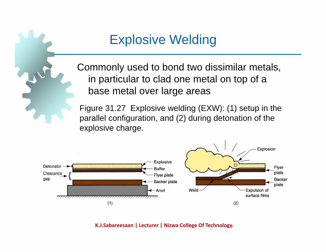
Commonly used to bond two dissimilar metals, in particular to clad one metal on top of a
g
in particular to clad one metal on top of a base metal over large areas
Figure 31.27 Explosive welding (EXW): (1) setup in theFigure 31.27 Explosive welding (EXW): (1) setup in the parallel configuration, and (2) during detonation of the explosive charge.
K.J.Sabareesaan | Lecturer | Nizwa College Of Technology.
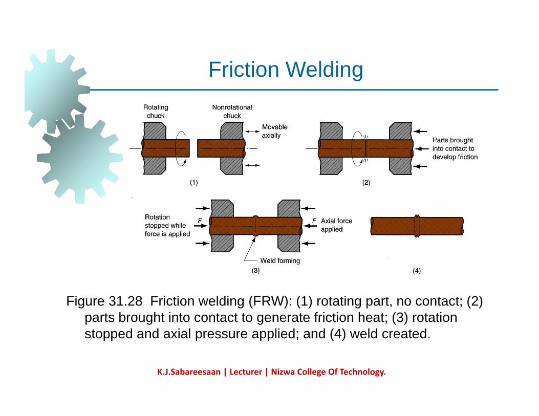
Friction Welding (FRW)Friction Welding (FRW)
SSW process in which coalescence is achieved b f i ti l h t bi d ithby frictional heat combined with pressure When properly carried out, no melting occurs at faying surfacesfaying surfacesNo filler metal, flux, or shielding gases normally usedProcess yields a narrow HAZCan be used to join dissimilar metalsWid l d i l bl tWidely used commercial process, amenable to automation and mass production
K.J.Sabareesaan | Lecturer | Nizwa College Of Technology.
Friction Weldingc o e d g
Figure 31.28 Friction welding (FRW): (1) rotating part, no contact; (2) parts brought into contact to generate friction heat; (3) rotation stopped and axial pressure applied; and (4) weld created.pp p pp ; ( )
K.J.Sabareesaan | Lecturer | Nizwa College Of Technology.
Weld QualityWeld Quality
Concerned with obtaining an acceptable weld joint that is strong and absent of defects, and the methods of inspecting and testing the joint to assure its qualitythe joint to assure its qualityTopics:
Residual stresses and distortionWelding defectsInspection and testing methods
K.J.Sabareesaan | Lecturer | Nizwa College Of Technology.
Welding DefectsWelding Defects
Cracks CavitiesSolid inclusions I f t h t bl tImperfect shape or unacceptable contour Incomplete fusion Miscellaneous defectsMiscellaneous defects
K.J.Sabareesaan | Lecturer | Nizwa College Of Technology.
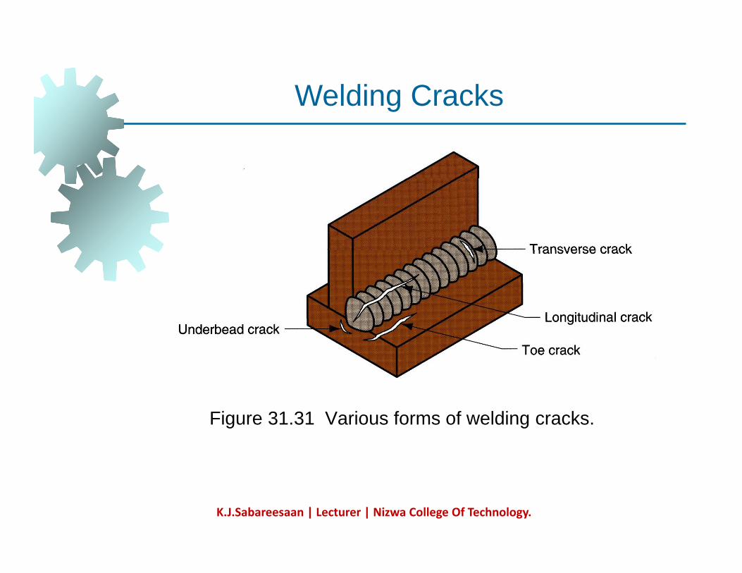
Welding CracksWelding Cracks
Fracture-type interruptions either in weld or in b t l dj t t ldbase metal adjacent to weld Serious defect because it is a discontinuity in the metal that significantly reduces strengththe metal that significantly reduces strength Caused by embrittlement or low ductility of weld and/or base metal combined with high
i d i irestraint during contraction In general, this defect must be repaired
K.J.Sabareesaan | Lecturer | Nizwa College Of Technology.
Welding Crackse d g C ac s
Figure 31.31 Various forms of welding cracks.
K.J.Sabareesaan | Lecturer | Nizwa College Of Technology.
CavitiesCavities
Two defect types, similar to defects found in ticastings:
1. Porosity - small voids in weld metal formed by gases entrapped during solidificationby gases entrapped during solidification
Caused by inclusion of atmospheric gases, sulfur in weld metal, or surface contaminants
2. Shrinkage voids - cavities formed by shrinkage during solidificationshrinkage during solidification
K.J.Sabareesaan | Lecturer | Nizwa College Of Technology.
Solid InclusionsSolid Inclusions
Solid inclusions - nonmetallic material t d i ld t lentrapped in weld metal
Most common form is slag inclusions generated during AW processes that use fluxgenerated during AW processes that use flux
Instead of floating to top of weld pool, globules of slag become encased during
lidifi isolidificationMetallic oxides that form during welding of certain metals such as aluminum whichcertain metals such as aluminum, which normally has a surface coating of Al2O3
K.J.Sabareesaan | Lecturer | Nizwa College Of Technology.
Incomplete Fusion
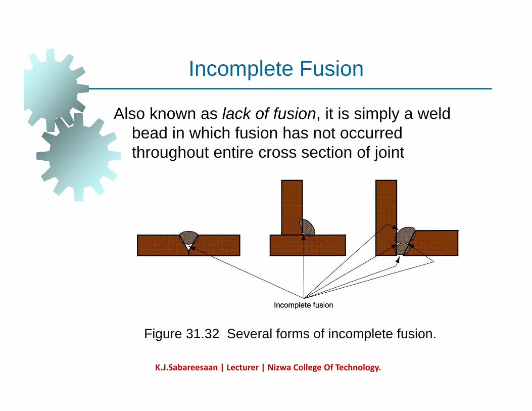
Also known as lack of fusion, it is simply a weld b d i hi h f i h t d
co p e e us o
bead in which fusion has not occurred throughout entire cross section of joint
Figure 31 32 Several forms of incomplete fusionFigure 31.32 Several forms of incomplete fusion.
K.J.Sabareesaan | Lecturer | Nizwa College Of Technology.
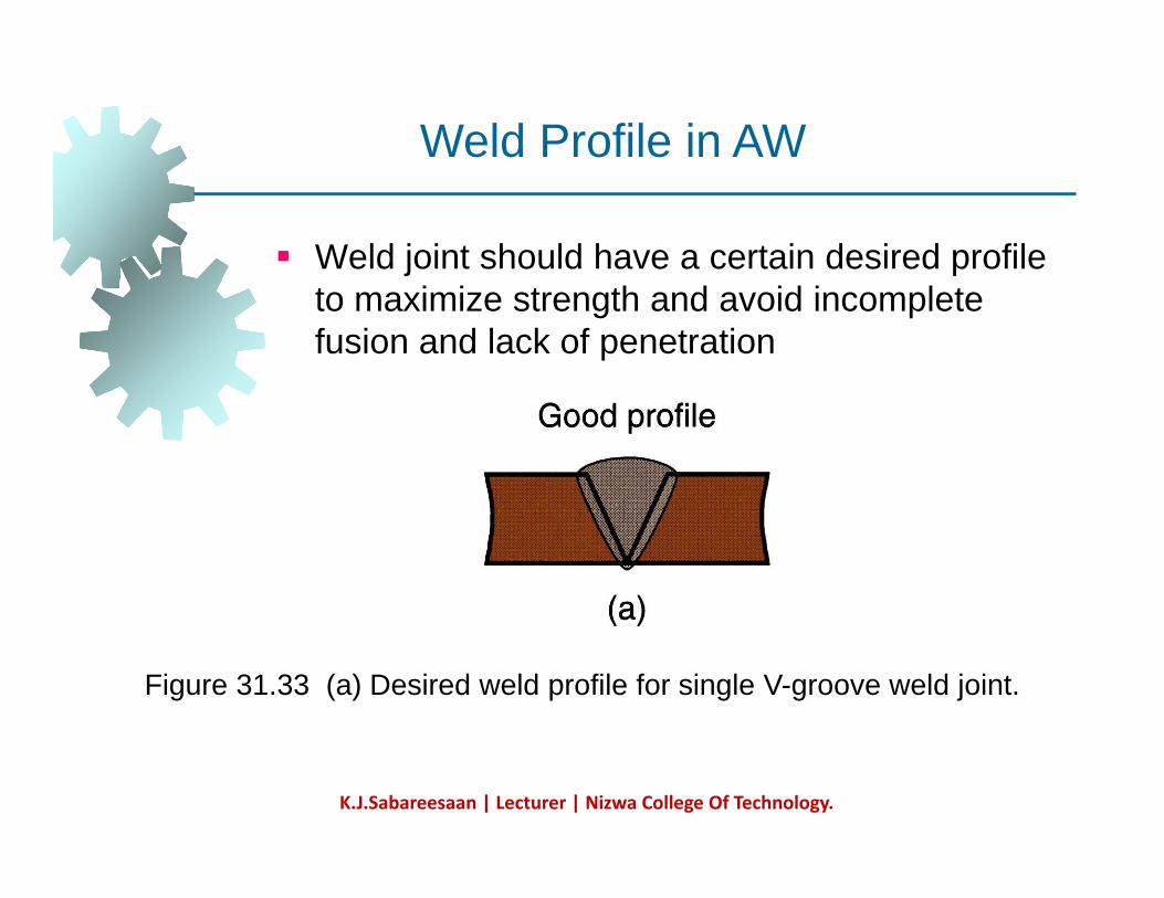
Weld Profile in AW
Weld joint should have a certain desired profile to maximize strength and avoid incomplete fusion and lack of penetration
Figure 31.33 (a) Desired weld profile for single V-groove weld joint.
K.J.Sabareesaan | Lecturer | Nizwa College Of Technology.
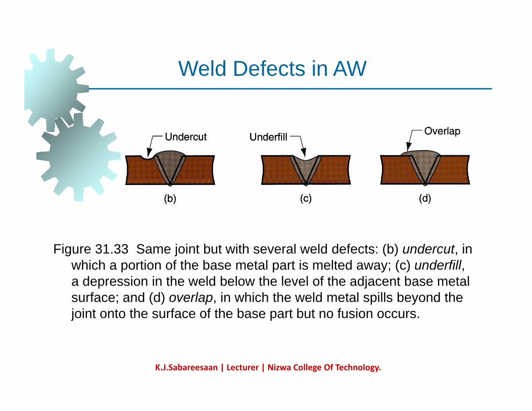
Weld Defects in AWe d e ec s
Figure 31.33 Same joint but with several weld defects: (b) undercut, in which a portion of the base metal part is melted away; (c) underfill, a depression in the weld below the level of the adjacent base metala depression in the weld below the level of the adjacent base metal surface; and (d) overlap, in which the weld metal spills beyond the joint onto the surface of the base part but no fusion occurs.
K.J.Sabareesaan | Lecturer | Nizwa College Of Technology.
Inspection and Testing MethodsInspection and Testing Methods
Visual inspection Nondestructive evaluation Destructive testing
K.J.Sabareesaan | Lecturer | Nizwa College Of Technology.
Visual InspectionVisual Inspection
Most widely used welding inspection method Human inspector visually examines for:
Conformance to dimensions WWarpage Cracks, cavities, incomplete fusion, and other surface defects
Limitations: Only surface defects are detectable Welding inspector must also determine if additional tests are warranted
K.J.Sabareesaan | Lecturer | Nizwa College Of Technology.
Nondestructive Evaluation (NDE) Tests
Ultrasonic testing - high frequency sound waves directed through specimen - crackswaves directed through specimen cracks, inclusions are detected by loss in sound transmission Radiographic testing - x-rays or gamma radiation provide photograph of internal flawsDye-penetrant and fluorescent-penetrantDye penetrant and fluorescent penetrant tests - methods for detecting small cracks and cavities that are open at surfaceMagnetic particle testing – iron filings sprinkled on surface reveal subsurface defects by distorting magnetic field in partdefects by distorting magnetic field in part
K.J.Sabareesaan | Lecturer | Nizwa College Of Technology.
Destructive TestingDestructive Testing
Tests in which weld is destroyed either during t ti t t t itesting or to prepare test specimen Mechanical tests - purpose is similar to conventional testing methods such as tensileconventional testing methods such as tensile tests, shear tests, etc Metallurgical tests - preparation of metallurgical
i ( h i h ) fspecimens (e.g., photomicrographs) of weldment to examine metallic structure, defects, extent and condition of heat affected ,zone, and similar phenomena
K.J.Sabareesaan | Lecturer | Nizwa College Of Technology.
WeldabilityWeldability
Capacity of a metal or combination of metals to b ld d i t it bl d i d t tbe welded into a suitably designed structure, and for the resulting weld joint(s) to possess the required metallurgical properties to perform q g p p psatisfactorily in intended service Good weldability characterized by:
E i h hi h ldi iEase with which welding process is accomplishedAbsence of weld defectsAbsence of weld defectsAcceptable strength, ductility, and toughness in welded joint
K.J.Sabareesaan | Lecturer | Nizwa College Of Technology.
Weldability Factors – Welding ProcessWeldability Factors Welding Process
Some metals or metal combinations can be dil ld d b b t diffi ltreadily welded by one process but are difficult
to weld by othersExample: stainless steel readily welded byExample: stainless steel readily welded by most AW and RW processes, but difficult to weld by OFW
K.J.Sabareesaan | Lecturer | Nizwa College Of Technology.
Weldability Factors – Base MetalWeldability Factors Base Metal
Some metals melt too easily; e.g., aluminumMetals with high thermal conductivity transfer heat away from weld, which causes problems; e.g., copperproblems; e.g., copper High thermal expansion and contraction in metal causes distortion problemsDissimilar metals pose problems in welding when their physical and/or mechanical properties are substantially differentproperties are substantially different
K.J.Sabareesaan | Lecturer | Nizwa College Of Technology.
Other Factors Affecting WeldabilityOther Factors Affecting Weldability
Filler metal Must be compatible with base metal(s) In general, elements mixed in liquid state that form a solid solution upon solidificationthat form a solid solution upon solidification will not cause a problem
Surface conditions Moisture can result in porosity in fusion zone O id d th fil t l fOxides and other films on metal surfaces can prevent adequate contact and fusion
K.J.Sabareesaan | Lecturer | Nizwa College Of Technology.
Design Considerations in WeldingDesign Considerations in Welding
Design for welding - product should be d i d f th t t ld d bldesigned from the start as a welded assembly, and not as a casting or forging or other formed shape pMinimum parts - welded assemblies should consist of fewest number of parts possible
E l ll ffi iExample: usually more cost efficient to perform simple bending operations on a part than to weld an assembly from flat plates y pand sheets
K.J.Sabareesaan | Lecturer | Nizwa College Of Technology.