Embed Size (px)
Citation preview
User Manual XI/ON10/2011 MN05002011Z-EN
replaces M001757-04, 06/2009
Analog I/O-Modules
ManufacturerEaton Automation AGSpinnereistrasse 8-14CH-9008 St. GallenSwitzerlandwww.eaton-automation.com www.eaton.com
Support
Original manualThe German version of this document is the original manual.
Translations of the original manualAll non-German editions of this document are translations of the originalmanual.
Editorial departmentMonika Jahn
Brand and product namesAll brand and product names are trademarks or registered trademarks of theowner concerned.
Copyright© Eaton Automation AG, CH-9008 St. Gallen
All rights reserved, also for the translation.
None of this document may be reproduced or processed, duplicated or distrib-uted by electronic systems in any form (print, photocopy, microfilm or anyother process) without the written permission of Eaton Automation AG,St. Gallen.
Subject to modifications.
Region North AmericaEaton CorporationElectrical Sector1111 Superior Ave.Cleveland, OH 44114United States877-ETN-CARE (877-386-2273)www.eaton.com
Other regionsPlease contact your supplier or send an E-Mail to:[email protected]
Imprint
2 XI/ON: Analog I/O-Modules 10/2011 MN05002011Z-EN www.eaton.com
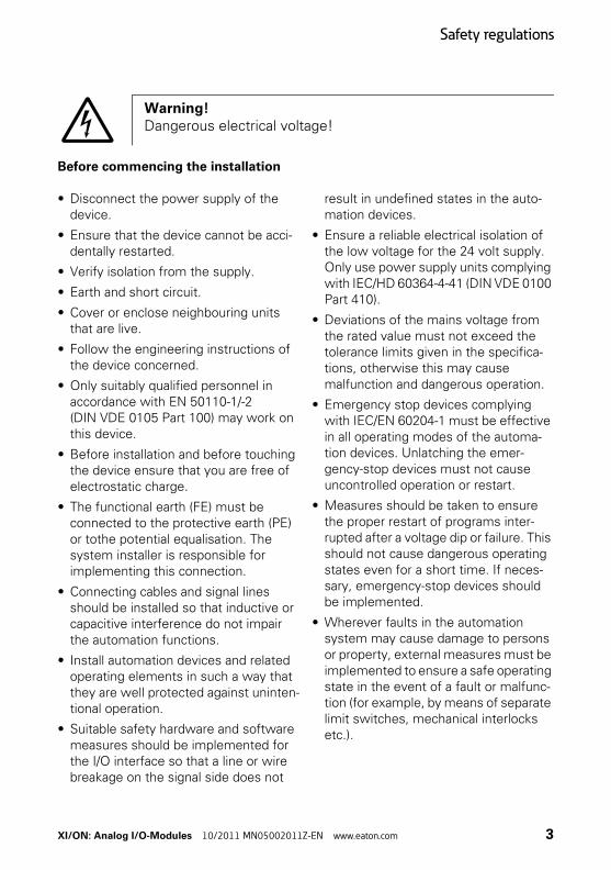
Before commencing the installation
• Disconnect the power supply of the device.
• Ensure that the device cannot be acci-dentally restarted.
• Verify isolation from the supply.
• Earth and short circuit.
• Cover or enclose neighbouring units that are live.
• Follow the engineering instructions of the device concerned.
• Only suitably qualified personnel in accordance with EN 50110-1/-2 (DIN VDE 0105 Part 100) may work on this device.
• Before installation and before touching the device ensure that you are free of electrostatic charge.
• The functional earth (FE) must be connected to the protective earth (PE) or tothe potential equalisation. The system installer is responsible for implementing this connection.
• Connecting cables and signal lines should be installed so that inductive or capacitive interference do not impair the automation functions.
• Install automation devices and related operating elements in such a way that they are well protected against uninten-tional operation.
• Suitable safety hardware and software measures should be implemented for the I/O interface so that a line or wire breakage on the signal side does not
result in undefined states in the auto-mation devices.
• Ensure a reliable electrical isolation of the low voltage for the 24 volt supply. Only use power supply units complying with IEC/HD 60364-4-41 (DIN VDE 0100 Part 410).
• Deviations of the mains voltage from the rated value must not exceed the tolerance limits given in the specifica-tions, otherwise this may cause malfunction and dangerous operation.
• Emergency stop devices complying with IEC/EN 60204-1 must be effective in all operating modes of the automa-tion devices. Unlatching the emer-gency-stop devices must not cause uncontrolled operation or restart.
• Measures should be taken to ensure the proper restart of programs inter-rupted after a voltage dip or failure. This should not cause dangerous operating states even for a short time. If neces-sary, emergency-stop devices should be implemented.
• Wherever faults in the automation system may cause damage to persons or property, external measures must be implemented to ensure a safe operating state in the event of a fault or malfunc-tion (for example, by means of separate limit switches, mechanical interlocks etc.).
Warning!Dangerous electrical voltage!
Safety regulations
XI/ON: Analog I/O-Modules 10/2011 MN05002011Z-EN www.eaton.com 3
• The electrical installation must be carried out in accordance with the rele-vant regulations (e.g. with regard to cable cross sections, fuses, PE).
• All work relating to transport, installa-tion, commissioning and maintenance must only be carried out by qualified personnel. (IEC/HD 60364 (DIN VDE 0100) and national work safety regulations).
Safety regulations
4 XI/ON: Analog I/O-Modules 10/2011 MN05002011Z-EN www.eaton.com
Table of contents
Table of contents
Table of contents . . . . . . . . . . . . . . . . . . . . . . . . . . . . 5
About This Manual. . . . . . . . . . . . . . . . . . . . . . . . . . 13Writing conventions. . . . . . . . . . . . . . . . . . . . . . . . . . . 13
1 The XI/ON Station. . . . . . . . . . . . . . . . . . . . . . . . . . . 15Dimensions . . . . . . . . . . . . . . . . . . . . . . . . . . . . . . . . . 15Technical data for the XI/ON station . . . . . . . . . . . . . . . . . . . . . . . . . . . . . . . . 22Technical data for the terminals . . . . . . . . . . . . . . . . . 26Designations of the base modules . . . . . . . . . . . . . . . 27Module designations and abbreviations . . . . . . . . . . . 29Wiring of the XI/ON modules . . . . . . . . . . . . . . . . . . . 30– Wiring of tension clamp connections . . . . . . . . . . . 31– Wiring of screw connections . . . . . . . . . . . . . . . . . . 32– Handling the push-in tension clamp terminals of
the XNE ECO modules . . . . . . . . . . . . . . . . . . . . . . . 33The supply modules . . . . . . . . . . . . . . . . . . . . . . . . . . . 34– Bus refreshing modules XN-BR-24VDC-D . . . . . . . 34– Power feeding modules
XN-PF-24VDC-D and XN-PF-120/230VAC-D . . . . . . 35
2 Analog Input Modules . . . . . . . . . . . . . . . . . . . . . . . 37General. . . . . . . . . . . . . . . . . . . . . . . . . . . . . . . . . . . . . 37Representation of the analog values. . . . . . . . . . . . . . 38– 16-bit or 12-bit representation . . . . . . . . . . . . . . . . 38– The two's complement in the number circle . . . . . . 39Equations and graphs for 16-bit representation . . . . . 40– Representation of current values in the range
0 mA…20 mA . . . . . . . . . . . . . . . . . . . . . . . . . . . . . 40– Representation of current values in the range
4 mA…20 mA . . . . . . . . . . . . . . . . . . . . . . . . . . . . . 42– Representation of temperature values and
resistance values for the XN-2AI-PT/NI-2/3 . . . . . . 44
XI/ON: Analog I/O-Modules 10/2011 MN05002011Z-EN www.eaton.com 5
Table of contents
– Representation of temperature and voltagevalues for the XN-2AI-THERMO-PI . . . . . . . . . . . . . 50
– Representation of the voltage values in the range0 V DC…10 V DC. . . . . . . . . . . . . . . . . . . . . . . . . . . 56
– Representation of the voltage values in the range-10 V DC…10 V DC . . . . . . . . . . . . . . . . . . . . . . . . . 58
– Example of the calculation of negative numerical values . . . . . . . . . . . . . . . . . . . . . . . . . . . . . . . . . . . . 60
Equations and graphs for 12-bit representation . . . . . 62– Representation of the current values in the range
0…20 mA . . . . . . . . . . . . . . . . . . . . . . . . . . . . . . . . 62– Representation of the current values in the range
4…20 mA . . . . . . . . . . . . . . . . . . . . . . . . . . . . . . . . 64– Representation of temperature values and
resistance values for the XN-2AI-PT/NI-2/3 . . . . . . 66– Representation of temperature and voltage
values for the XN-2AI-THERMO-PI . . . . . . . . . . . . . 72– Representation of the voltage values in the range
0 V DC…10 V DC. . . . . . . . . . . . . . . . . . . . . . . . . . . 78– Representation of the voltage values in the range
-10 V DC…10 V DC . . . . . . . . . . . . . . . . . . . . . . . . . 80– LEDs . . . . . . . . . . . . . . . . . . . . . . . . . . . . . . . . . . . . . 83XN-1AI-I(0/4…20MA) . . . . . . . . . . . . . . . . . . . . . . . . . 84– Technical data . . . . . . . . . . . . . . . . . . . . . . . . . . . . . 85– Diagnostics messages . . . . . . . . . . . . . . . . . . . . . . . 87– Module parameters . . . . . . . . . . . . . . . . . . . . . . . . . 88– Base modules . . . . . . . . . . . . . . . . . . . . . . . . . . . . . 88– Connection diagrams . . . . . . . . . . . . . . . . . . . . . . . . 89XN-2AI-I(0/4…20MA) . . . . . . . . . . . . . . . . . . . . . . . . . 91– Technical data . . . . . . . . . . . . . . . . . . . . . . . . . . . . . 92– Diagnostics messages . . . . . . . . . . . . . . . . . . . . . . . 94– Module parameters (per channel) . . . . . . . . . . . . . . 95– Base modules. . . . . . . . . . . . . . . . . . . . . . . . . . . . . . 96– Connection diagrams . . . . . . . . . . . . . . . . . . . . . . . . 97XN-1AI-U(-10/0…+10VDC) . . . . . . . . . . . . . . . . . . . . . 98– Technical data . . . . . . . . . . . . . . . . . . . . . . . . . . . . . 99– Diagnostics messages . . . . . . . . . . . . . . . . . . . . . . 101– Module parameters . . . . . . . . . . . . . . . . . . . . . . . . 102– Base modules . . . . . . . . . . . . . . . . . . . . . . . . . . . . 102– Connection diagrams . . . . . . . . . . . . . . . . . . . . . . . 103
6 XI/ON: Analog I/O-Modules 10/2011 MN05002011Z-EN www.eaton.com
Table of contents
XN-2AI-U(-10/0…+10VDC) . . . . . . . . . . . . . . . . . . . . 105– Technical data . . . . . . . . . . . . . . . . . . . . . . . . . . . . 106– Diagnostic messages . . . . . . . . . . . . . . . . . . . . . . . 108– Module parameters (per channel) . . . . . . . . . . . . . 109– Base modules. . . . . . . . . . . . . . . . . . . . . . . . . . . . . 110– Connection diagrams . . . . . . . . . . . . . . . . . . . . . . . 111XN-2AI-PT/NI-2/3 . . . . . . . . . . . . . . . . . . . . . . . . . . . 112– Technical data . . . . . . . . . . . . . . . . . . . . . . . . . . . . 113– Diagnostic messages . . . . . . . . . . . . . . . . . . . . . . . 115– Module parameters (per channel) . . . . . . . . . . . . . 116– Base modules. . . . . . . . . . . . . . . . . . . . . . . . . . . . . 117– Connection diagrams . . . . . . . . . . . . . . . . . . . . . . . 118XN-2AI-THERMO-PI . . . . . . . . . . . . . . . . . . . . . . . . . . 119– Technical data . . . . . . . . . . . . . . . . . . . . . . . . . . . . 120– Diagnostic messages . . . . . . . . . . . . . . . . . . . . . . . 123– Module parameters (per channel) . . . . . . . . . . . . . 124– Base modules. . . . . . . . . . . . . . . . . . . . . . . . . . . . . 125– Connection diagram . . . . . . . . . . . . . . . . . . . . . . . 126XN-4AI-U/I . . . . . . . . . . . . . . . . . . . . . . . . . . . . . . . . . 127– Technical data . . . . . . . . . . . . . . . . . . . . . . . . . . . . 128– Diagnostic messages . . . . . . . . . . . . . . . . . . . . . . . 131– Module parameters (per channel) . . . . . . . . . . . . 132– Base modules. . . . . . . . . . . . . . . . . . . . . . . . . . . . . 133– Connection diagram. . . . . . . . . . . . . . . . . . . . . . . . 134XNE-8AI-U/I-4PT/NI. . . . . . . . . . . . . . . . . . . . . . . . . . 135– Technical data . . . . . . . . . . . . . . . . . . . . . . . . . . . . 137– Diagnostic messages . . . . . . . . . . . . . . . . . . . . . . . 140– Module parameters (per channel) . . . . . . . . . . . . . 142– Connection diagram. . . . . . . . . . . . . . . . . . . . . . . . 144– Process input data . . . . . . . . . . . . . . . . . . . . . . . . . 145– Standard value representation
for voltage / current . . . . . . . . . . . . . . . . . . . . . . . . 146– Extended Range value representation
for voltage / current . . . . . . . . . . . . . . . . . . . . . . . . 152– Value representation for process automation (NE43)
for voltage /current . . . . . . . . . . . . . . . . . . . . . . . . 158– Standard value representation
for PT-/ NI- and resistance measurement . . . . . . . 164
XI/ON: Analog I/O-Modules 10/2011 MN05002011Z-EN www.eaton.com 7
Table of contents
3 Analog Output Modules . . . . . . . . . . . . . . . . . . . . 175General. . . . . . . . . . . . . . . . . . . . . . . . . . . . . . . . . . . . 175Equations and graphs for 16-bit representation . . . . 176– Representation of the current values in the range
0…20 mA . . . . . . . . . . . . . . . . . . . . . . . . . . . . . . . 176– Representation of the current values in the range
4…20 mA . . . . . . . . . . . . . . . . . . . . . . . . . . . . . . . 178– Representation of the voltage values in the range
0…10 V DC . . . . . . . . . . . . . . . . . . . . . . . . . . . . . . 180– Representation of the voltage values in the range
-10 V DC…10 V DC . . . . . . . . . . . . . . . . . . . . . . . . 182– Calculation of hexadecimal/binary values
for negative decimal values. . . . . . . . . . . . . . . . . . 184Equations and graphs for 12-bit representation . . . . 186– Representation of the current values in the range
0…20 mA . . . . . . . . . . . . . . . . . . . . . . . . . . . . . . . 187– Representation of the current values in the range
4 mA…20 mA . . . . . . . . . . . . . . . . . . . . . . . . . . . . 189– Representation of the voltage values in the range
0…10 V DC . . . . . . . . . . . . . . . . . . . . . . . . . . . . . . 191– Representation of the voltage values in the range
-10 V DC…10 V DC . . . . . . . . . . . . . . . . . . . . . . . . 193– Calculation of hexadecimal/binary values
for negative decimal values. . . . . . . . . . . . . . . . . . 195– LEDs . . . . . . . . . . . . . . . . . . . . . . . . . . . . . . . . . . . . 197XN-1AO-I(0/4…20MA) . . . . . . . . . . . . . . . . . . . . . . . 198– Technical data . . . . . . . . . . . . . . . . . . . . . . . . . . . . 199– Diagnostic messages . . . . . . . . . . . . . . . . . . . . . . . 201– Module parameters . . . . . . . . . . . . . . . . . . . . . . . 201– Base modules. . . . . . . . . . . . . . . . . . . . . . . . . . . . . 202– Connection diagram . . . . . . . . . . . . . . . . . . . . . . . 202XN-2AO-I(0/4…20MA) . . . . . . . . . . . . . . . . . . . . . . . 203– Technical data . . . . . . . . . . . . . . . . . . . . . . . . . . . . 204– Diagnostic messages . . . . . . . . . . . . . . . . . . . . . . . 206– Module parameters (per channel) . . . . . . . . . . . . 206– Base modules. . . . . . . . . . . . . . . . . . . . . . . . . . . . . 207– Connection diagram . . . . . . . . . . . . . . . . . . . . . . . 207XN-2AO-U (-10/0…+10VDC) . . . . . . . . . . . . . . . . . . . 208– Technical data . . . . . . . . . . . . . . . . . . . . . . . . . . . . 209– Diagnostic messages . . . . . . . . . . . . . . . . . . . . . . . 211
8 XI/ON: Analog I/O-Modules 10/2011 MN05002011Z-EN www.eaton.com
Table of contents
– Module parameters . . . . . . . . . . . . . . . . . . . . . . . 211– Base modules. . . . . . . . . . . . . . . . . . . . . . . . . . . . . 212– Connection diagram . . . . . . . . . . . . . . . . . . . . . . . 212XNE-4AO-U/I . . . . . . . . . . . . . . . . . . . . . . . . . . . . . . . 213– Technical data . . . . . . . . . . . . . . . . . . . . . . . . . . . . 215– Diagnostic messages . . . . . . . . . . . . . . . . . . . . . . . 217– Module parameters (per channel) . . . . . . . . . . . . . 218– Connection diagram. . . . . . . . . . . . . . . . . . . . . . . . 220– Standard value representation . . . . . . . . . . . . . . . 221– Extended Range value representation. . . . . . . . . . 225– Value representation for process automation
(NE43). . . . . . . . . . . . . . . . . . . . . . . . . . . . . . . . . . . 229
4 Integration in PROFIBUS-DP . . . . . . . . . . . . . . . . 233General. . . . . . . . . . . . . . . . . . . . . . . . . . . . . . . . . . . . 233Process input data . . . . . . . . . . . . . . . . . . . . . . . . . . . 234– Data structure with 16-bit representation . . . . . . 234– Data structure with 12-bit representation . . . . . . 235Process output data . . . . . . . . . . . . . . . . . . . . . . . . . . 236– Data structure with 16-bit representation . . . . . . 236– Data structure with 12-bit representation . . . . . . 237Parameter data structure. . . . . . . . . . . . . . . . . . . . . . 238– XN-1AI-I(0/4…20MA) . . . . . . . . . . . . . . . . . . . . . . 239– XN-2AI-I(0/4…20MA) . . . . . . . . . . . . . . . . . . . . . 239– XN-1AI-U(-10/0…+10VDC) . . . . . . . . . . . . . . . . . . 240– XN-2AI-U(-10/0…+10VDC) . . . . . . . . . . . . . . . . . . 240– XN-2AI-PT/NI-2/3 . . . . . . . . . . . . . . . . . . . . . . . . . 241– XN-2AI-THERMO-PI . . . . . . . . . . . . . . . . . . . . . . . 241– XN-4AI-U/I . . . . . . . . . . . . . . . . . . . . . . . . . . . . . . . 242– XNE-8AI-U/I-4PT/NI . . . . . . . . . . . . . . . . . . . . . . . 242– XN-1AO-I(0/4…20MA) . . . . . . . . . . . . . . . . . . . . . 243– XN-2AO-I(0/4…20MA) . . . . . . . . . . . . . . . . . . . . . 243– XN-2AO-U(-10/0…+10VDC) . . . . . . . . . . . . . . . . . 244– XNE-4AO-U/I . . . . . . . . . . . . . . . . . . . . . . . . . . . . . 245Meaning of the parameter data . . . . . . . . . . . . . . . . 246Diagnostic . . . . . . . . . . . . . . . . . . . . . . . . . . . . . . . . . 253
5 Integration in CANopen . . . . . . . . . . . . . . . . . . . . 257Process input data / process output data . . . . . . . . . 257
XI/ON: Analog I/O-Modules 10/2011 MN05002011Z-EN www.eaton.com 9
Table of contents
Objects for the process data . . . . . . . . . . . . . . . . . . . 258– Overview . . . . . . . . . . . . . . . . . . . . . . . . . . . . . . . . 258– 6401hex Read Analog Input 16 Bit . . . . . . . . . . . . 259– 6411hex Write Analog Output 16 Bit . . . . . . . . . . 260Objects for Interrupt behaviour . . . . . . . . . . . . . . . . . 261– 6421hex Analog Input Interrupt Trigger Selection 262– 6422hex Analog Input Interrupt Source. . . . . . . . . 264– 6423hex Analog Input Global Interrupt Enable . . . 265– 6424hex Analog Input Interrupt
Upper Limit Integer . . . . . . . . . . . . . . . . . . . . . . . . 266– 6425hex Analog Input Interrupt
Lower Limit Integer . . . . . . . . . . . . . . . . . . . . . . . . 267– 6426hex Analog Input Interrupt Delta Unsigned. . 268– 6427hex Analog Input Interrupt
Negative Delta Unsigned. . . . . . . . . . . . . . . . . . . . 269– 6428hex Analog Input Interrupt
Positive Delta Unsigned. . . . . . . . . . . . . . . . . . . . . 270Objects for the substitute output value in the eventof an error . . . . . . . . . . . . . . . . . . . . . . . . . . . . . . . . . 271– Overview . . . . . . . . . . . . . . . . . . . . . . . . . . . . . . . . 271– 6443hex Analog Output Error Mode . . . . . . . . . . . 272– 6444hex Analog Output Error State. . . . . . . . . . . . 273Objects for parameterisation. . . . . . . . . . . . . . . . . . . 274– 5420hex Manu Spec Analog Input Range . . . . . . . 274– XN-2AI-THERMO-PI . . . . . . . . . . . . . . . . . . . . . . . . 280– 5440hex Manu Spec Analog Output Range . . . . . 284Object for the Device Profile and the I/O types . . . . 289– 67FFhex Device Type DS401 . . . . . . . . . . . . . . . . . 289Emergencies. . . . . . . . . . . . . . . . . . . . . . . . . . . . . . . . 290
6 Integration in DeviceNet . . . . . . . . . . . . . . . . . . . 293Analog Input Voltage Module Class (VSC106) . . . . . 293Analog Output Voltage Module Class (VSC107) . . . . 298Analog Input Current Module Class (VSC108). . . . . . 303Analog Output Current Module Class (VSC109) . . . . 307Analog Input PT100/NI Module Class (VSC110) . . . . 310Analog Input THERMO Module Class (VSC111) . . . . 316Analog VERSATILE Module Class (VSC118) . . . . . . . 322
10 XI/ON: Analog I/O-Modules 10/2011 MN05002011Z-EN www.eaton.com
Table of contents
Index . . . . . . . . . . . . . . . . . . . . . . . . . . . . . . . . . . . . . 329
XI/ON: Analog I/O-Modules 10/2011 MN05002011Z-EN www.eaton.com 11
Table of contents
12 XI/ON: Analog I/O-Modules 10/2011 MN05002011Z-EN www.eaton.com
About This Manual
Writing conventions
About This Manual
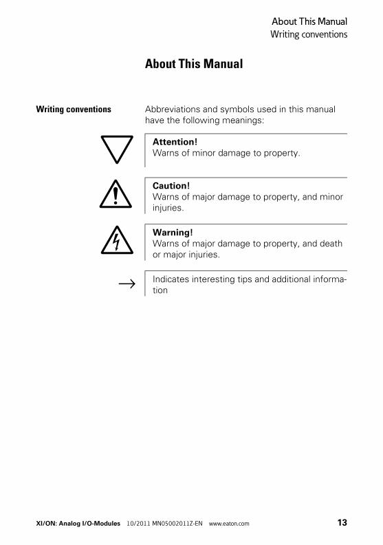
Writing conventions Abbreviations and symbols used in this manual have the following meanings:
Attention!Warns of minor damage to property.
Caution!Warns of major damage to property, and minor injuries.
Warning!Warns of major damage to property, and death or major injuries.
→ Indicates interesting tips and additional informa-tion
XI/ON: Analog I/O-Modules 10/2011 MN05002011Z-EN www.eaton.com 13
About This Manual
Writing conventions
14 XI/ON: Analog I/O-Modules 10/2011 MN05002011Z-EN www.eaton.com
1 The XI/ON Station
Dimensions
1 The XI/ON Station
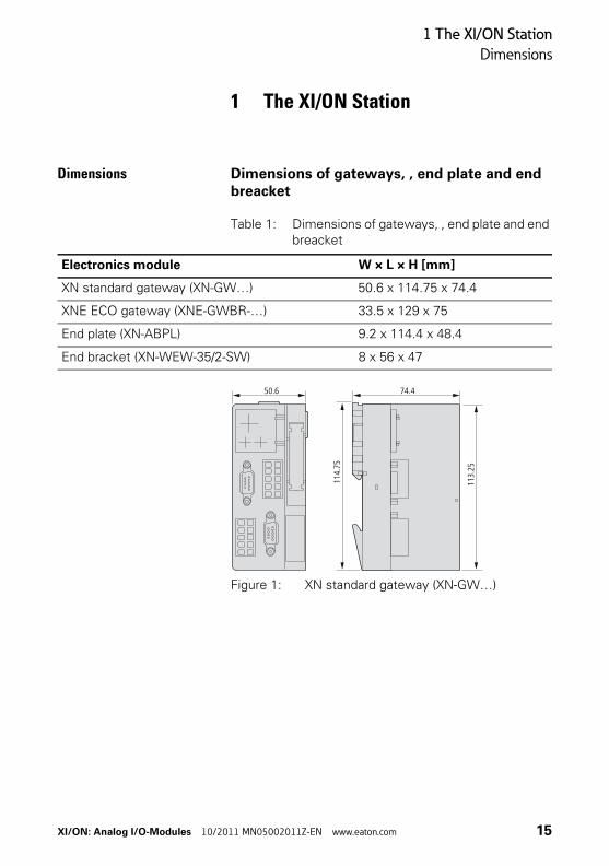
Dimensions Dimensions of gateways, , end plate and end breacket
Table 1: Dimensions of gateways, , end plate and end breacket
Figure 1: XN standard gateway (XN-GW…)
Electronics module W × L × H [mm]
XN standard gateway (XN-GW…) 50.6 x 114.75 x 74.4
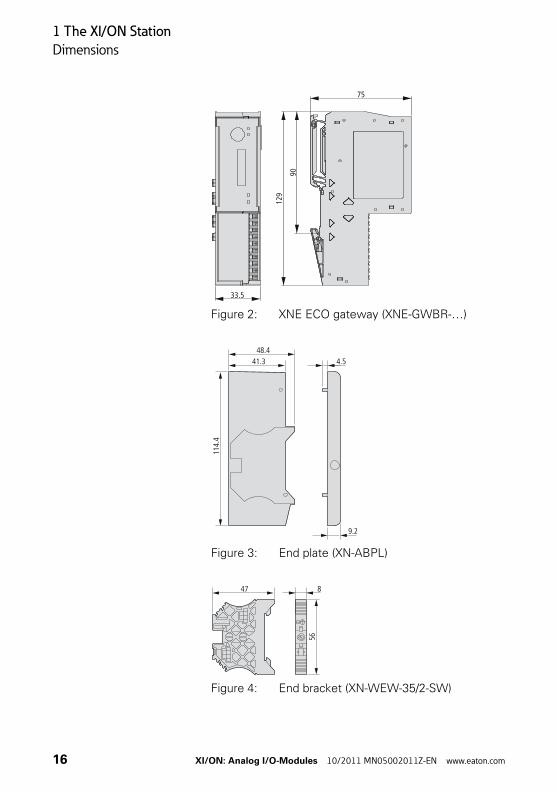
XNE ECO gateway (XNE-GWBR-…) 33.5 x 129 x 75
End plate (XN-ABPL) 9.2 x 114.4 x 48.4
End bracket (XN-WEW-35/2-SW) 8 x 56 x 47
113.
25
114.
75
50.6 74.4
XI/ON: Analog I/O-Modules 10/2011 MN05002011Z-EN www.eaton.com 15
1 The XI/ON Station
Dimensions
Figure 2: XNE ECO gateway (XNE-GWBR-…)
Figure 3: End plate (XN-ABPL)
Figure 4: End bracket (XN-WEW-35/2-SW)
33.5
129
90
75
48.4
114.
4
41.3 4.5
9.2
56
47 8
16 XI/ON: Analog I/O-Modules 10/2011 MN05002011Z-EN www.eaton.com
1 The XI/ON Station
Dimensions
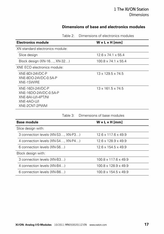
Dimensions of base and electronics modules
Table 2: Dimensions of electronics modules
Table 3: Dimensions of base modules
Electronics module W × L × H [mm]
XN standard electronics module:
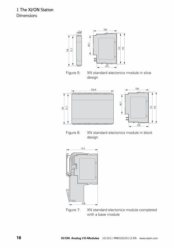
Slice design 12.6 x 74.1 x 55.4
Block design (XN-16…, XN-32…) 100.8 x 74.1 x 55.4
XNE ECO electronics module:
XNE-8DI-24VDC-PXNE-8DO-24VDC-0.5A-PXNE-1SWIRE
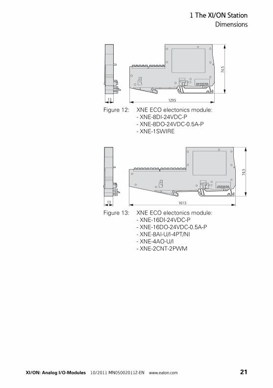
13 x 129.5 x 74.5
XNE-16DI-24VDC-PXNE-16DO-24VDC-0.5A-PXNE-8AI-U/I-4PT/NIXNE-4AO-U/IXNE-2CNT-2PWM
13 x 161.5 x 74.5
Base module W × L × H [mm]
Slice design with:
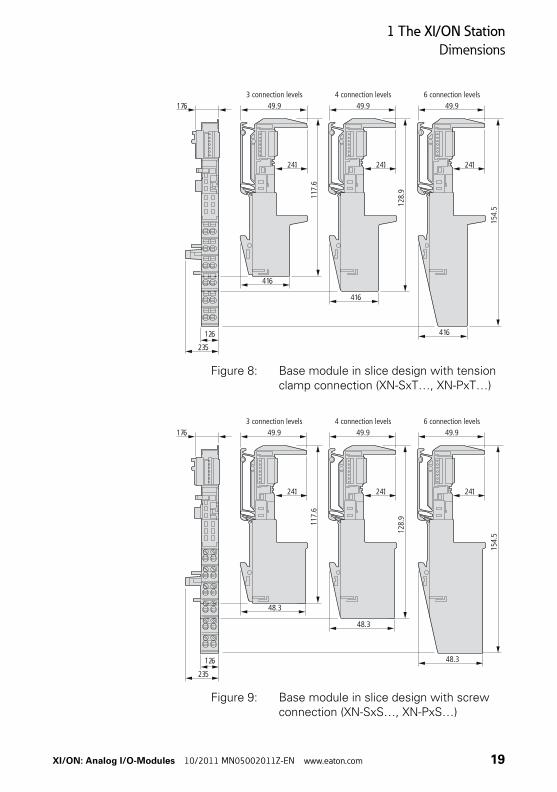
3 connection levels (XN-S3…, XN-P3…) 12.6 x 117.6 x 49.9
4 connection levels (XN-S4…, XN-P4…) 12.6 x 128.9 x 49.9
6 connection levels (XN-S6…) 12.6 x 154.5 x 49.9
Block design with:
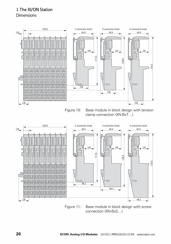
3 connection levels (XN-B3…) 100.8 x 117.6 x 49.9
4 connection levels (XN-B4…) 100.8 x 128.9 x 49.9
6 connection levels (XN-B6…) 100.8 x 154.5 x 49.9
XI/ON: Analog I/O-Modules 10/2011 MN05002011Z-EN www.eaton.com 17
1 The XI/ON Station
Dimensions
Figure 5: XN standard electonics module in slice design
Figure 6: XN standard electonics module in block design
Figure 7: XN standard electonics module completed with a base module
72.1
74.1
12.6
72.146
.1
74. 1
55.4
47.372
.1
74.1
100.8
72.146
.1
74. 1
55.4
47.3
74.5
67.8
18 XI/ON: Analog I/O-Modules 10/2011 MN05002011Z-EN www.eaton.com
1 The XI/ON Station
Dimensions
Figure 8: Base module in slice design with tension clamp connection (XN-SxT…, XN-PxT…)
Figure 9: Base module in slice design with screw connection (XN-SxS…, XN-PxS…)
49.9
24.1
117.
6
128.
9
154.
5
41.6
49.9
24.1
41.6
49.9
24.1
41.6
17.6
23.5
12.6
3 connection levels 4 connection levels 6 connection levels
48.3
49.9
24.1
117.
6
128.
9
154.
5
48.3
49.9
24.1
49.9
24.1
23.5
12.6
17.6
48.3
3 connection levels 4 connection levels 6 connection levels
XI/ON: Analog I/O-Modules 10/2011 MN05002011Z-EN www.eaton.com 19
1 The XI/ON Station
Dimensions
Figure 10: Base module in block design with tension clamp connection (XN-BxT…)
Figure 11: Base module in block design with screw connection (XN-BxS…)
23.5
17.6100.8
49.9
24.1
117.
6
128.
9
154.
5
41.6
49.9
24.1
41.6
49.9
24.1
41.6
3 connection levels 4 connection levels 6 connection levels
23.5
17.6100.8
48.3
49.9
24.1
117.
6
128.
9
154.
5
48.3
49.9
24.1
49.93 connection levels 4 connection levels 6 connection levels
24.1
48.3
20 XI/ON: Analog I/O-Modules 10/2011 MN05002011Z-EN www.eaton.com
1 The XI/ON Station
Dimensions
Figure 12: XNE ECO electonics module: - XNE-8DI-24VDC-P- XNE-8DO-24VDC-0.5A-P- XNE-1SWIRE
Figure 13: XNE ECO electonics module: - XNE-16DI-24VDC-P- XNE-16DO-24VDC-0.5A-P- XNE-8AI-U/I-4PT/NI- XNE-4AO-U/I- XNE-2CNT-2PWM
129.5
74.5
13
161.5
74.5
13
XI/ON: Analog I/O-Modules 10/2011 MN05002011Z-EN www.eaton.com 21
1 The XI/ON Station
Technical data for the XI/ON station
Technical data for the XI/ON station
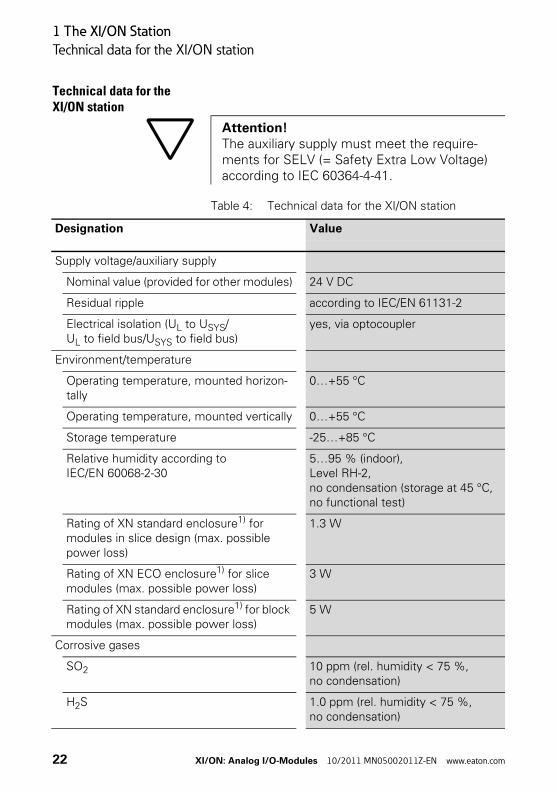
Table 4: Technical data for the XI/ON station
Attention!The auxiliary supply must meet the require-ments for SELV (= Safety Extra Low Voltage) according to IEC 60364-4-41.
Designation Value
Supply voltage/auxiliary supply
Nominal value (provided for other modules) 24 V DC
Residual ripple according to IEC/EN 61131-2
Electrical isolation (UL to USYS/UL to field bus/USYS to field bus)
yes, via optocoupler
Environment/temperature
Operating temperature, mounted horizon-tally
0…+55 °C
Operating temperature, mounted vertically 0…+55 °C
Storage temperature -25…+85 °C
Relative humidity according to IEC/EN 60068-2-30
5…95 % (indoor), Level RH-2, no condensation (storage at 45 °C, no functional test)
Rating of XN standard enclosure1) for modules in slice design (max. possible power loss)
1.3 W
Rating of XN ECO enclosure1) for slice modules (max. possible power loss)
3 W
Rating of XN standard enclosure1) for block modules (max. possible power loss)
5 W
Corrosive gases
SO2 10 ppm (rel. humidity < 75 %, no condensation)
H2S 1.0 ppm (rel. humidity < 75 %, no condensation)
22 XI/ON: Analog I/O-Modules 10/2011 MN05002011Z-EN www.eaton.com
1 The XI/ON Station
Technical data for the XI/ON station
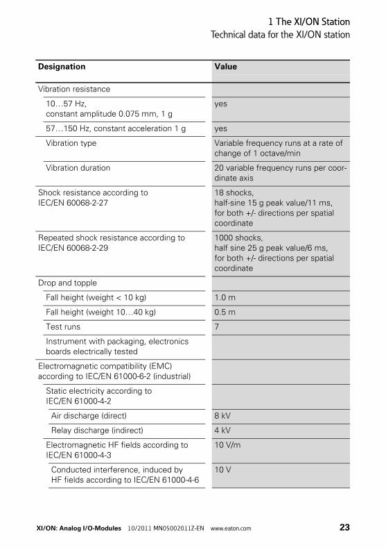
Vibration resistance
10…57 Hz, constant amplitude 0.075 mm, 1 g
yes
57…150 Hz, constant acceleration 1 g yes
Vibration type Variable frequency runs at a rate of change of 1 octave/min
Vibration duration 20 variable frequency runs per coor-dinate axis
Shock resistance according to IEC/EN 60068-2-27
18 shocks, half-sine 15 g peak value/11 ms, for both +/- directions per spatial coordinate
Repeated shock resistance according to IEC/EN 60068-2-29
1000 shocks, half sine 25 g peak value/6 ms,for both +/- directions per spatial coordinate
Drop and topple
Fall height (weight < 10 kg) 1.0 m
Fall height (weight 10…40 kg) 0.5 m
Test runs 7
Instrument with packaging, electronics boards electrically tested
Electromagnetic compatibility (EMC) according to IEC/EN 61000-6-2 (industrial)
Static electricity according to IEC/EN 61000-4-2
Air discharge (direct) 8 kV
Relay discharge (indirect) 4 kV
Electromagnetic HF fields according to IEC/EN 61000-4-3
10 V/m
Conducted interference, induced by HF fields according to IEC/EN 61000-4-6
10 V
Designation Value
XI/ON: Analog I/O-Modules 10/2011 MN05002011Z-EN www.eaton.com 23
1 The XI/ON Station
Technical data for the XI/ON station
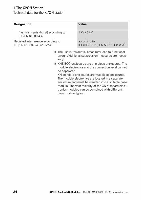
1) The use in residential areas may lead to functional errors. Additional suppression measures are neces-sary!
1) XNE ECO enclosures are one-piece enclosures. The module electronics and the connection level cannot be separated.XN standard enclosures are two-piece enclosures. The module electronics are located in a separate enclosure and must be inserted into a suitable base module. The vast majority of the XN standard elec-tronics modules can be combined with different base module types.
Fast transients (burst) according to IEC/EN 61000-4-4
1 kV / 2 kV
Radiated interference according to IEC/EN 61000-6-4 (industrial)
according to IEC/CISPR 11 / EN 55011, Class A1)
Designation Value
24 XI/ON: Analog I/O-Modules 10/2011 MN05002011Z-EN www.eaton.com
1 The XI/ON Station
Technical data for the XI/ON station
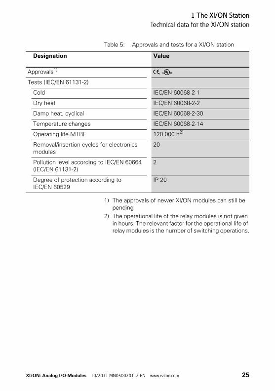
Table 5: Approvals and tests for a XI/ON station
1) The approvals of newer XI/ON modules can still be pending
2) The operational life of the relay modules is not given in hours. The relevant factor for the operational life of relay modules is the number of switching operations.
Designation Value
Approvals1) ,
Tests (IEC/EN 61131-2)
Cold IEC/EN 60068-2-1
Dry heat IEC/EN 60068-2-2
Damp heat, cyclical IEC/EN 60068-2-30
Temperature changes IEC/EN 60068-2-14
Operating life MTBF 120 000 h2)
Removal/insertion cycles for electronics modules
20
Pollution level according to IEC/EN 60664 (IEC/EN 61131-2)
2
Degree of protection according to IEC/EN 60529
IP 20
XI/ON: Analog I/O-Modules 10/2011 MN05002011Z-EN www.eaton.com 25
1 The XI/ON Station
Technical data for the terminals
Technical data for the terminals
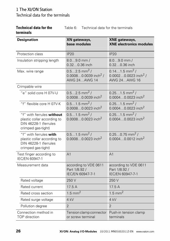
Table 6: Technical data for the terminals
Designation XN gateways, base modules
XNE gateways, XNE electronics modules
Protection class IP20 IP20
Insulation stripping length 8.0…9.0 mm / 0.32…0.36 inch
8.0…9.0 mm / 0.32…0.36 inch
Max. wire range 0.5…2.5 mm2 / 0.0008…0.0039 inch2 / AWG 24…AWG 14
0.14…1.5 mm2 / 0.0002…0.0023 inch2 / AWG 24…AWG 16
Crimpable wire
“e” solid core H 07V-U 0.5…2.5 mm2 / 0.0008…0.0039 inch2
0.25…1.5 mm2 / 0.0004…0.0023 inch2
“f” flexible core H 07V-K 0.5…1.5 mm2 / 0.0008…0.0023 inch2
0.25…1.5 mm2 / 0.0004…0.0023 inch2
“f” with ferrules without plastic collar according to DIN 46228-1 (ferrules crimped gas-tight)
0.5…1.5 mm2 / 0.0008…0.0023 inch2
0.25…1.5 mm2 / 0.0004…0.0023 inch2
“f” with ferrules with plastic collar according to DIN 46228-1 (ferrules crimped gas-tight)
0.5…1.5 mm2 / 0.0008…0.0023 inch2
0.25…0.75 mm2 / 0.0004…0.0012 inch2
Test finger according to IEC/EN 60947-1
A1 A1
Measurement data according to VDE 0611 Part 1/8.92 / IEC/EN 60947-7-1
according to VDE 0611 Part 1/8.92 / IEC/EN 60947-7-1
Rated voltage 250 V 250 V
Rated current 17.5 A 17.5 A
Rated cross section 1.5 mm2 1.5 mm2
Rated surge voltage 4 kV 4 kV
Pollution degree 2 2
Connection method in TOP direction
Tension clamp connector or screw terminal
Push-in tension clamp terminals
26 XI/ON: Analog I/O-Modules 10/2011 MN05002011Z-EN www.eaton.com
1 The XI/ON Station
Designations of the base modules
Designations of the base modules
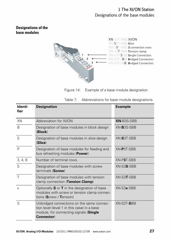
Figure 14: Example of a base module designation
Table 7: Abbreviations for base module designations
1
3
2
1
3
2
XN : XI/ONS :
3 :T :
S :B :
B:
S3TSBB
liceconnection rowsension clampingle Connectorsridged Connectorsridged Connectors
-S3T-SBBXN- 3T-SBBXN-S T-SBBXN-S3 -SBBXN-S3T- BBXN-S3T-S BXN-S3T-SB
Identi-fier
Designation Example
XN Abbreviation for XI/ON XN-B3S-SBB
B Designation of base modules in block design (Block)
XN-B3S-SBB
S Designation of base modules in slice design (Slice)
XN-S3T-SBB
P Designation of base modules for feeding and bus refreshing modules (Power)
XN-P3T-SBB
3, 4, 6 Number of terminal rows. XN-P3T-SBB
S Designation of base modules with screw terminals (Screw)
XN-S3S-SBB
T Designation of base modules with tension clamp connection (Tension Clamp)
XN-S3T-SBB
x Optionally S or T in the designation of base modules with screw or tension clamp connec-tions (Screw / Tension)
XN-S3x-SBB
S Unbridged connections on the same connec-tion level (level 1 in this case) in a base module, for connecting signals (Single Connector)
XN-S3T-SBB
XI/ON: Analog I/O-Modules 10/2011 MN05002011Z-EN www.eaton.com 27
1 The XI/ON Station
Designations of the base modules
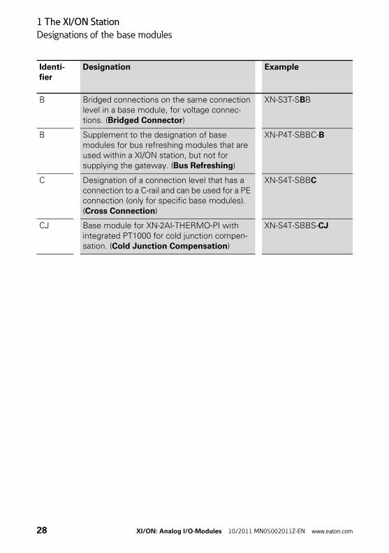
B Bridged connections on the same connection level in a base module, for voltage connec-tions. (Bridged Connector)
XN-S3T-SBB
B Supplement to the designation of base modules for bus refreshing modules that are used within a XI/ON station, but not for supplying the gateway. (Bus Refreshing)
XN-P4T-SBBC-B
C Designation of a connection level that has a connection to a C-rail and can be used for a PE connection (only for specific base modules). (Cross Connection)
XN-S4T-SBBC
CJ Base module for XN-2AI-THERMO-PI with integrated PT1000 for cold junction compen-sation. (Cold Junction Compensation)
XN-S4T-SBBS-CJ
Identi-fier
Designation Example
28 XI/ON: Analog I/O-Modules 10/2011 MN05002011Z-EN www.eaton.com
1 The XI/ON Station
Module designations and abbreviations
Module designations and abbreviations
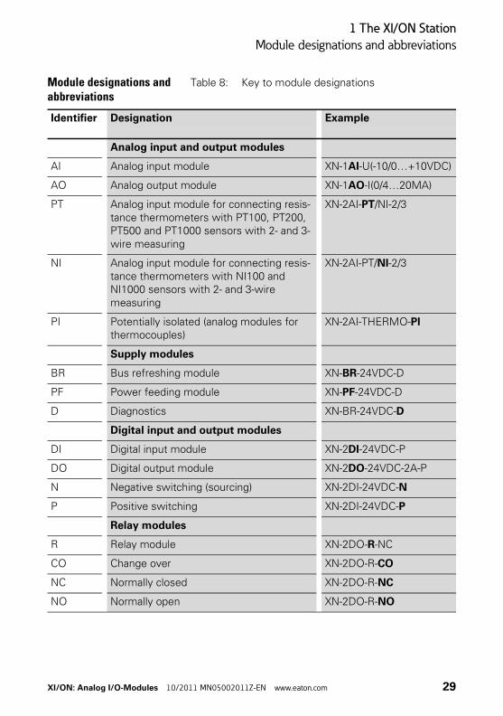
Table 8: Key to module designations
Identifier Designation Example
Analog input and output modules
AI Analog input module XN-1AI-U(-10/0…+10VDC)
AO Analog output module XN-1AO-I(0/4…20MA)
PT Analog input module for connecting resis-tance thermometers with PT100, PT200, PT500 and PT1000 sensors with 2- and 3-wire measuring
XN-2AI-PT/NI-2/3
NI Analog input module for connecting resis-tance thermometers with NI100 and NI1000 sensors with 2- and 3-wire measuring
XN-2AI-PT/NI-2/3
PI Potentially isolated (analog modules for thermocouples)
XN-2AI-THERMO-PI
Supply modules
BR Bus refreshing module XN-BR-24VDC-D
PF Power feeding module XN-PF-24VDC-D
D Diagnostics XN-BR-24VDC-D
Digital input and output modules
DI Digital input module XN-2DI-24VDC-P
DO Digital output module XN-2DO-24VDC-2A-P
N Negative switching (sourcing) XN-2DI-24VDC-N
P Positive switching XN-2DI-24VDC-P
Relay modules
R Relay module XN-2DO-R-NC
CO Change over XN-2DO-R-CO
NC Normally closed XN-2DO-R-NC
NO Normally open XN-2DO-R-NO
XI/ON: Analog I/O-Modules 10/2011 MN05002011Z-EN www.eaton.com 29
1 The XI/ON Station
Wiring of the XI/ON modules
Wiring of the XI/ON modules
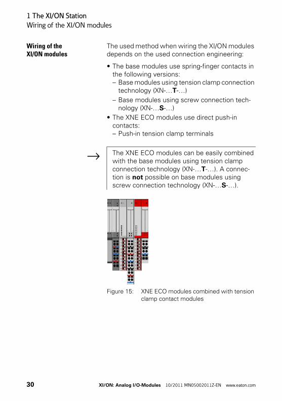
The used method when wiring the XI/ON modules depends on the used connection engineering:
• The base modules use spring-finger contacts in the following versions:– Base modules using tension clamp connection
technology (XN-…T-…)
– Base modules using screw connection tech-nology (XN-…S-…)
• The XNE ECO modules use direct push-in contacts:– Push-in tension clamp terminals
Figure 15: XNE ECO modules combined with tension clamp contact modules
→ The XNE ECO modules can be easily combined with the base modules using tension clamp connection technology (XN-…T-…). A connec-tion is not possible on base modules using screw connection technology (XN-…S-…).
30 XI/ON: Analog I/O-Modules 10/2011 MN05002011Z-EN www.eaton.com
1 The XI/ON Station
Wiring of the XI/ON modules
Wiring of tension clamp connections
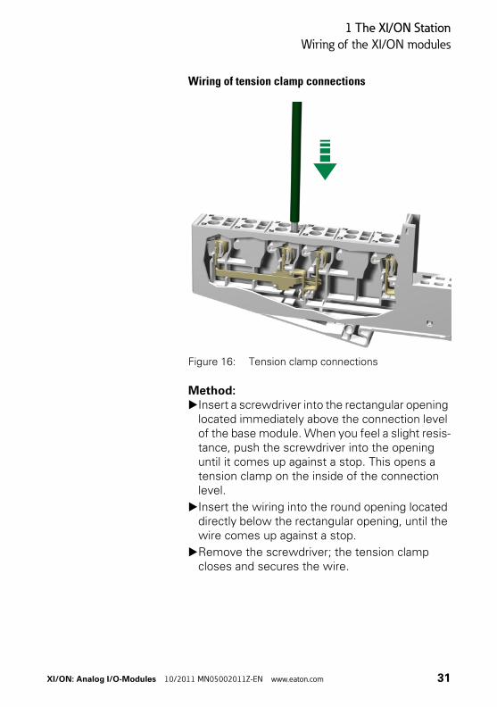
Figure 16: Tension clamp connections
Method:▶Insert a screwdriver into the rectangular opening
located immediately above the connection level of the base module. When you feel a slight resis-tance, push the screwdriver into the opening until it comes up against a stop. This opens a tension clamp on the inside of the connection level.
▶Insert the wiring into the round opening located directly below the rectangular opening, until the wire comes up against a stop.
▶Remove the screwdriver; the tension clamp closes and secures the wire.
XI/ON: Analog I/O-Modules 10/2011 MN05002011Z-EN www.eaton.com 31
1 The XI/ON Station
Wiring of the XI/ON modules
Wiring of screw connections
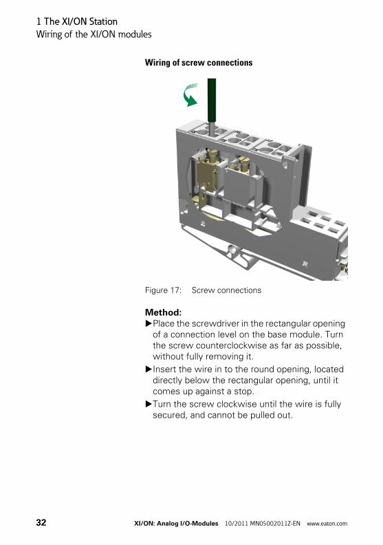
Figure 17: Screw connections
Method:▶Place the screwdriver in the rectangular opening
of a connection level on the base module. Turn the screw counterclockwise as far as possible, without fully removing it.
▶Insert the wire in to the round opening, located directly below the rectangular opening, until it comes up against a stop.
▶Turn the screw clockwise until the wire is fully secured, and cannot be pulled out.
32 XI/ON: Analog I/O-Modules 10/2011 MN05002011Z-EN www.eaton.com
1 The XI/ON Station
Wiring of the XI/ON modules
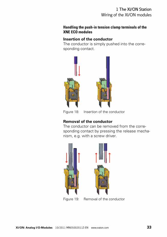
Handling the push-in tension clamp terminals of the XNE ECO modules
Insertion of the conductorThe conductor is simply pushed into the corre-sponding contact.
Figure 18: Insertion of the conductor
Removal of the conductorThe conductor can be removed from the corre-sponding contact by pressing the release mecha-nism, e.g. with a screw driver.
Figure 19: Removal of the conductor
XI/ON: Analog I/O-Modules 10/2011 MN05002011Z-EN www.eaton.com 33
1 The XI/ON Station
The supply modules
The supply modules A detailed description of these power supply modules can be found in the manual:
• User Manual XI/ON:Digital I/O modules, supply modules
Bus refreshing modules XN-BR-24VDC-D
The bus refreshing modules provide:
• 5 V DC for the internal XI/ON module bus and the neighbouring gateway.
• 24 V DC (permissible range according to IEC/EN 61131-2) as the supply for the module electronics and the field. This 24 V DC supply voltage is distributed throughout the XI/ON station as a separate cable.
This is electrically isolated from the neighbouring supply module on the left.
Attention!If the XI/ON station contains a gateway without an integrated power supply unit (XN-GW-…), the first bus refreshing module must be fitted directly to the right of a gateway. This provides the 5 V DC power supply to the gateway when connected to a special base module.
Attention!Only the base modules XN-P3x-SBB or XN-P4x-SBBC (as the first module to the right of the gateway) can be used to supply the gateway.
34 XI/ON: Analog I/O-Modules 10/2011 MN05002011Z-EN www.eaton.com
1 The XI/ON Station
The supply modules
Power feeding modules XN-PF-24VDC-D and XN-PF-120/230VAC-D
The power feeding modules are used to supply the various XI/ON modules with the field voltage of 24 V DC (XN-PF-24VDC-D) or 120/230 V AC (XN-PF-120/230VAC-D). They are used when different potential groups need to be set up within a XI/ON station, or in the event that the supply would otherwise be inadequate for the rated current requirements of the XI/ON modules. They are electrically isolated from the adjacent supply group on the left.
The ash-grey cover of the base modules for power feeding modules make them clearly distinguish-able from the base modules for the XI/ON I/O modules.
XN-PF-120/230VAC-DThe following modules can be supplied from a preceding XN-PF-120/230VAC-D:
• XN-2DI-120/230VAC
• XN-2DO-120/230VAC-0.5A
Warning!Power feeding modules cannot be used to provide the 5 V DC supply for XI/ON gateways.
Caution!Relay modules must not be supplied from a preceding XN-PF-120/230VAC-D!The nominal voltage at the supply terminals is 24 V DC (≙ coil voltage)!The relay modules can be externally loaded by up to 230 V AC (≙ contact voltage).
XI/ON: Analog I/O-Modules 10/2011 MN05002011Z-EN www.eaton.com 35
1 The XI/ON Station
The supply modules
36 XI/ON: Analog I/O-Modules 10/2011 MN05002011Z-EN www.eaton.com
2 Analog Input Modules
General
2 Analog Input Modules
General Analog input modules (AI) process normalised electrical signals, convert them to digital values and transmit the corresponding measured value to the gateway via the internal module bus.
The electronics on the module bus of the analog input modules is isolated from the field level via optocouplers and is protected against reverse polarity.
Analog input modules are built in slice design. XN standard electronics modules are completed by base modules with tension clamp or screw connection. XNE ECO electronics modules do not require a base module.
Supported signal ranges0…20 mA4…20 mA0…10 V DC-10…+10 V DC
Connectable sensorsPlatinum sensors (PT100, PT200, PT500, PT1000)Nickel sensors (NI100, NI1000, NI1000TK5000)Thermocouples (types B, E, J, K, N, R, S, T)
→ For the representation of current and voltage values with special operation modes (e.g. Extended Range and NE43) other equations and parameter settings must be applyed. Please read the subchapters «Value representation» of the corresponding module.
XI/ON: Analog I/O-Modules 10/2011 MN05002011Z-EN www.eaton.com 37
2 Analog Input Modules
Representation of the analog values
Representation of the analog values
16-bit or 12-bit representation
The analog values can be represented as either 16-bit or 12-bit values. The two's complement nota-tion of the number allows both positive and nega-tive values to be represented.
16-bit representation:The 16-bit representation is implemented in two's complement notation. 2 bytes of process data are fully assigned.
12-bit representation:The value is represented in two's complement notation for voltage measurement (output) and temperature measurement. The value is repre-sented in binary format for current measurement (output) and resistance measurement. The 12-bit value is mapped left-justified in the process data so that it is compatible (e.g. with WIN bloc).The diagnostics data is integrated in the process input data and is assigned to 4 bits (right-justified).→ “Data structure with 12-bit representation” Page 235
38 XI/ON: Analog I/O-Modules 10/2011 MN05002011Z-EN www.eaton.com
2 Analog Input Modules
Representation of the analog values
The two's complement in the number circle
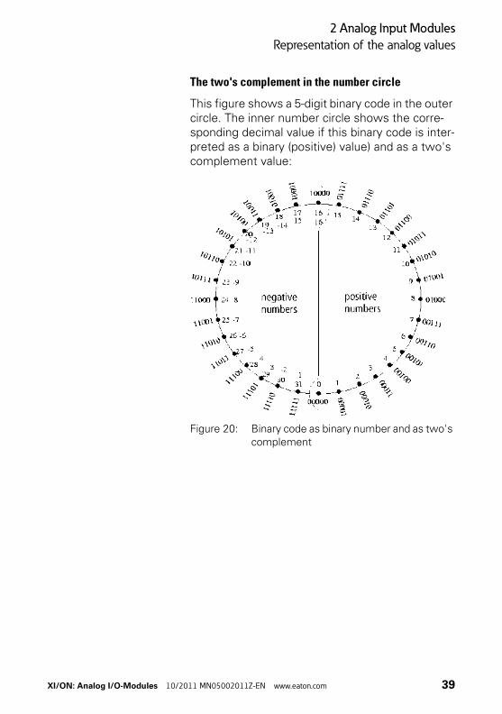
This figure shows a 5-digit binary code in the outer circle. The inner number circle shows the corre-sponding decimal value if this binary code is inter-preted as a binary (positive) value) and as a two's complement value:
Figure 20: Binary code as binary number and as two's complement
XI/ON: Analog I/O-Modules 10/2011 MN05002011Z-EN www.eaton.com 39
2 Analog Input Modules
Equations and graphs for 16-bit representation
Equations and graphs for 16-bit representation
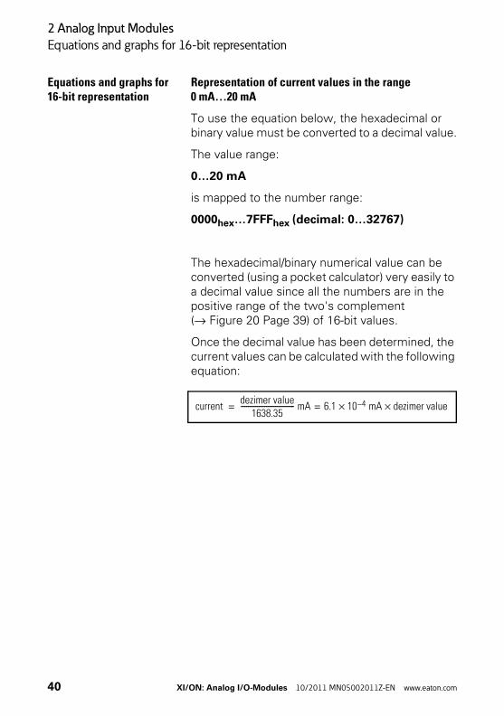
Representation of current values in the range0 mA…20 mA
To use the equation below, the hexadecimal or binary value must be converted to a decimal value.
The value range:
0…20 mA
is mapped to the number range:
0000hex…7FFFhex (decimal: 0…32767)
The hexadecimal/binary numerical value can be converted (using a pocket calculator) very easily to a decimal value since all the numbers are in the positive range of the two's complement (→ Figure 20 Page 39) of 16-bit values.
Once the decimal value has been determined, the current values can be calculated with the following equation:
currentdezimer value
1638.35------------------------------ mA 6.1 10× 4– mA dezimer value×==
40 XI/ON: Analog I/O-Modules 10/2011 MN05002011Z-EN www.eaton.com

2 Analog Input Modules
Equations and graphs for 16-bit representation
Figure 21: Representation of current values in relation to the decimal values in the coordinate system
XI/ON: Analog I/O-Modules 10/2011 MN05002011Z-EN www.eaton.com 41
2 Analog Input Modules
Equations and graphs for 16-bit representation
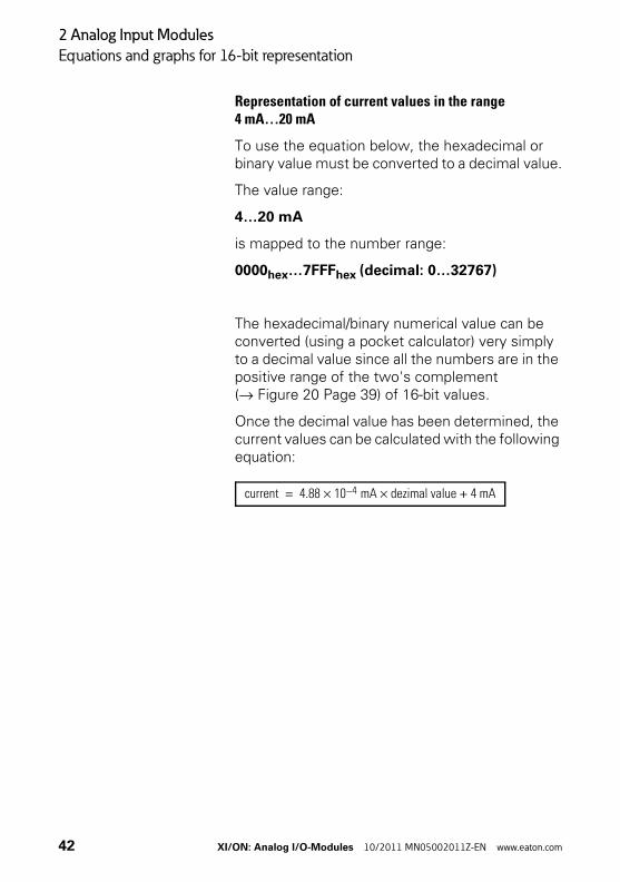
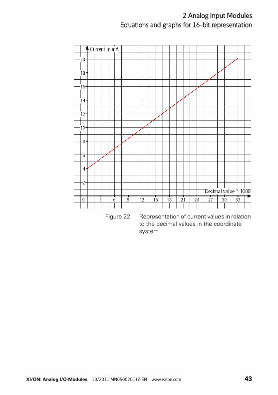
Representation of current values in the range4 mA…20 mA
To use the equation below, the hexadecimal or binary value must be converted to a decimal value.
The value range:
4…20 mA
is mapped to the number range:
0000hex…7FFFhex (decimal: 0…32767)
The hexadecimal/binary numerical value can be converted (using a pocket calculator) very simply to a decimal value since all the numbers are in the positive range of the two's complement (→ Figure 20 Page 39) of 16-bit values.
Once the decimal value has been determined, the current values can be calculated with the following equation:
current 4.88 10 4– mA× dezimal value 4 mA+×=
42 XI/ON: Analog I/O-Modules 10/2011 MN05002011Z-EN www.eaton.com
2 Analog Input Modules
Equations and graphs for 16-bit representation
Figure 22: Representation of current values in relation to the decimal values in the coordinate system
XI/ON: Analog I/O-Modules 10/2011 MN05002011Z-EN www.eaton.com 43
2 Analog Input Modules
Equations and graphs for 16-bit representation
Representation of temperature values andresistance values for the XN-2AI-PT/NI-2/3
To use the equations below, the hexadecimal or binary value must be converted to a decimal value.
The hexadecimal/binary numerical values for the negative number range cannot be converted (using a pocket calculator) easily to a decimal value since the numbers are coded in the two's comple-ment notation (→ Figure 20 Page 39).
All numerical values in the range 0000…7FFFhex represent positive numerical values in two's complement notation. Numbers in this range can be converted to a decimal value with a pocket calculator. This applies also to binary numbers with 0 as the most significant bit (bit 16).
All numerical values in the range 8000…FFFFhex represent negative values in two's complement notation. This applies also to binary numbers with 1 as the most significant bit (bit 16). The following examples shows the conversion to a decimal number:
→ “Example of the calculation of negative numerical values” Page 60
44 XI/ON: Analog I/O-Modules 10/2011 MN05002011Z-EN www.eaton.com
2 Analog Input Modules
Equations and graphs for 16-bit representation
Once the decimal value has been determined, the temperature values can be calculated according to the parameters defined.
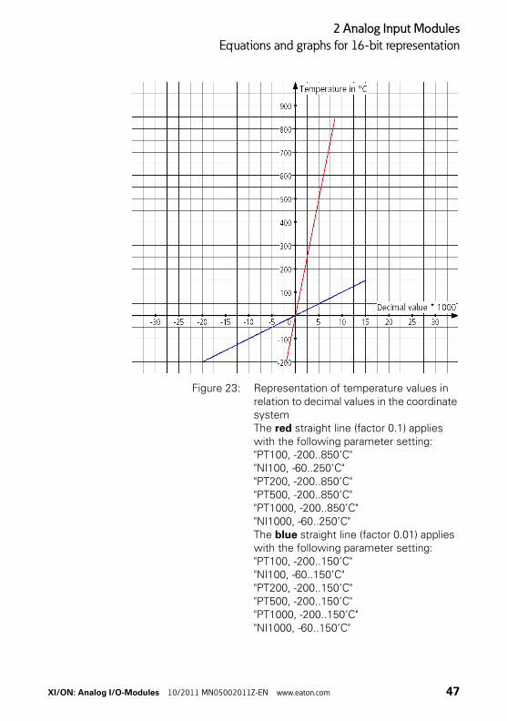
The following applies to the parameter setting of
• "PT100, -200..850’C"
• "NI100, -60..250’C"
• "PT200, -200..850’C"
• "PT500, -200..850’C"
• "PT1000, -200..850’C"
• "NI1000, -60..250’C"
The value range:
-200 °C…-0.1 °C
is mapped to the number range:
F830hex…FFFFhex (decimal: -2000…-1).
The value range:
0…850 °C
is mapped to the number range:
0000hex…2134hex (decimal: 0…8500).
temperature 0.1 °C dezimal value×=
XI/ON: Analog I/O-Modules 10/2011 MN05002011Z-EN www.eaton.com 45
2 Analog Input Modules
Equations and graphs for 16-bit representation
The following applies to the parameter setting of
• "PT100, -200..150’C"
• "NI100, -60..150’C"
• "PT200, -200..150’C"
• "PT500, -200..150’C"
• "PT1000, -200..150’C"
• "NI1000, -60..150’C"
The value range:
-200…-0.01 °C
is mapped to the number range:
B1E0hex…FFFFhex (decimal: -20000 to -1).
The value range:
0…150 °C
is mapped to the number range:
0000hex…3A98hex (decimal: 0…15000).
temperature 0.01 °C dezimal value×=
46 XI/ON: Analog I/O-Modules 10/2011 MN05002011Z-EN www.eaton.com
2 Analog Input Modules
Equations and graphs for 16-bit representation
Figure 23: Representation of temperature values in relation to decimal values in the coordinate systemThe red straight line (factor 0.1) applies with the following parameter setting:"PT100, -200..850’C""NI100, -60..250’C""PT200, -200..850’C""PT500, -200..850’C""PT1000, -200..850’C""NI1000, -60..250’C"The blue straight line (factor 0.01) applies with the following parameter setting:"PT100, -200..150’C""NI100, -60..150’C""PT200, -200..150’C""PT500, -200..150’C""PT1000, -200..150’C""NI1000, -60..150’C"
XI/ON: Analog I/O-Modules 10/2011 MN05002011Z-EN www.eaton.com 47
2 Analog Input Modules
Equations and graphs for 16-bit representation
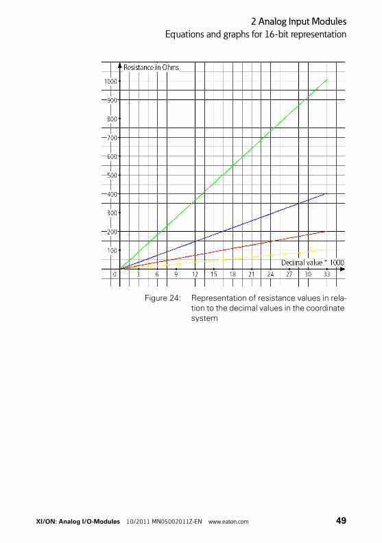
The parameter setting for the measurement of resistance values only requires positive numer-ical values (hexadecimal/binary) for representation. The positive numerical values can be converted (with the pocket calculator) very easily to a decimal value.
The value range:
0…100 Ω; 0…200 Ω; 0…400 Ω; 0…1000 Ω
is mapped to the number range:
0000hex…7FFFhex (decimal: 0…32767)
Once the decimal value has been determined, the resistance values can be calculated according to the parameters defined.
The following equations apply:
"Resistance, 0..100 Ohm" (yellow straight line):
"Resistance, 0..200 Ohm" (red straight line):
"Resistance, 0..400 Ohm" (blue straight line):
"Resistance, 0..1000 Ohm" (green straight line):
resistance 0.00305 Ω dezimal value×=
resistance 0.00610 Ω dezimal value×=
resistance 0.01221 Ω dezimal value×=
resistance 0.03052 Ω dezimal value×=
48 XI/ON: Analog I/O-Modules 10/2011 MN05002011Z-EN www.eaton.com
2 Analog Input Modules
Equations and graphs for 16-bit representation
Figure 24: Representation of resistance values in rela-tion to the decimal values in the coordinate system
XI/ON: Analog I/O-Modules 10/2011 MN05002011Z-EN www.eaton.com 49
2 Analog Input Modules
Equations and graphs for 16-bit representation
Representation of temperature and voltagevalues for the XN-2AI-THERMO-PI
To use the equations below, the hexadecimal or binary value must be converted to a decimal value.
The hexadecimal/binary numerical values for the negative number range cannot be converted (using a pocket calculator) easily to a decimal value since the numbers are coded in the two's comple-ment notation (→ Figure 20 Page 39).
All numerical values in the range 0000…7FFFhex represent positive numerical values in two's complement notation. Numbers in this range can be converted to a decimal value with a pocket calculator. This applies also to binary numbers with 0 as the most significant bit (bit 16).
All numerical values in the range 8000…FFFFhex represent negative values in two's complement notation. This applies also to binary numbers with 1 as the most significant bit (bit 16). The conver-sion to a decimal value shows: → “Example of the calculation of negative numerical values” Page 60.
50 XI/ON: Analog I/O-Modules 10/2011 MN05002011Z-EN www.eaton.com
2 Analog Input Modules
Equations and graphs for 16-bit representation
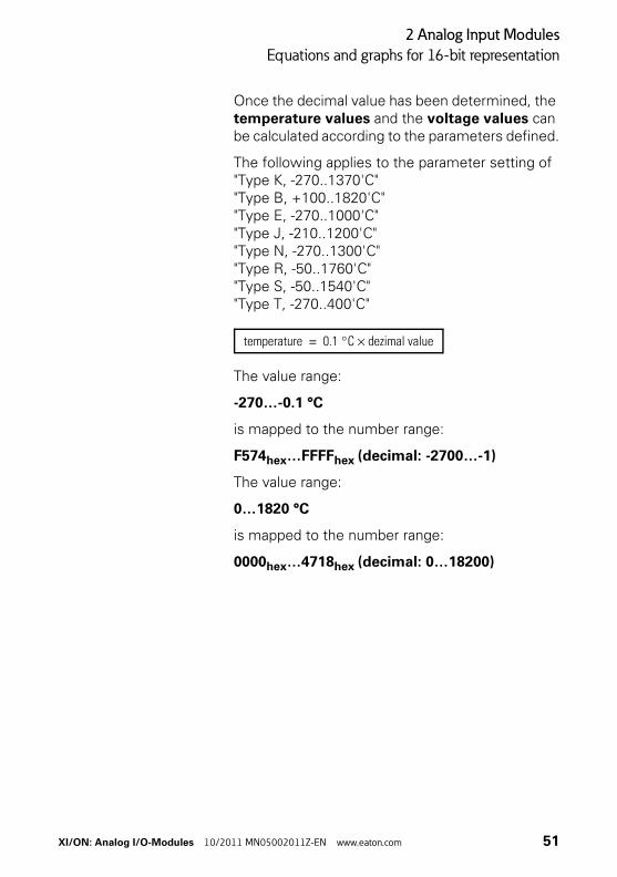
Once the decimal value has been determined, the temperature values and the voltage values can be calculated according to the parameters defined.
The following applies to the parameter setting of"Type K, -270..1370'C""Type B, +100..1820'C""Type E, -270..1000'C""Type J, -210..1200'C""Type N, -270..1300'C""Type R, -50..1760'C""Type S, -50..1540'C""Type T, -270..400'C"
The value range:
-270…-0.1 °C
is mapped to the number range:
F574hex…FFFFhex (decimal: -2700…-1)
The value range:
0…1820 °C
is mapped to the number range:
0000hex…4718hex (decimal: 0…18200)
temperature 0.1 °C dezimal value×=
XI/ON: Analog I/O-Modules 10/2011 MN05002011Z-EN www.eaton.com 51
2 Analog Input Modules
Equations and graphs for 16-bit representation
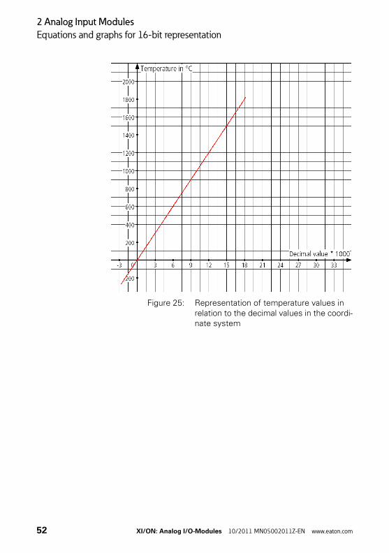
Figure 25: Representation of temperature values in relation to the decimal values in the coordi-nate system
52 XI/ON: Analog I/O-Modules 10/2011 MN05002011Z-EN www.eaton.com
2 Analog Input Modules
Equations and graphs for 16-bit representation
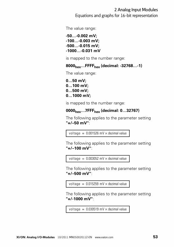
The value range:
-50…-0.002 mV;-100…-0.003 mV;-500…-0.015 mV;-1000…-0.031 mV
is mapped to the number range:
8000hex…FFFFhex (decimal: -32768…-1)
The value range:
0…50 mV;0…100 mV;0…500 mV;0…1000 mV;
is mapped to the number range:
0000hex…7FFFhex (decimal: 0…32767)
The following applies to the parameter setting "+/–50 mV":
The following applies to the parameter setting "+/–100 mV":
The following applies to the parameter setting "+/–500 mV":
The following applies to the parameter setting"+/-1000 mV":
voltage 0.001526 mV dezimal value×=
voltage 0.003052 mV dezimal value×=
voltage 0.015259 mV dezimal value×=
voltage 0.030519 mV dezimal value×=
XI/ON: Analog I/O-Modules 10/2011 MN05002011Z-EN www.eaton.com 53
2 Analog Input Modules
Equations and graphs for 16-bit representation
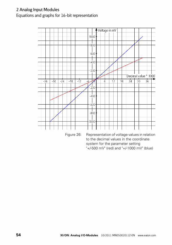
Figure 26: Representation of voltage values in relation to the decimal values in the coordinate system for the parameter setting "+/-500 mV" (red) and "+/-1000 mV" (blue)
54 XI/ON: Analog I/O-Modules 10/2011 MN05002011Z-EN www.eaton.com
2 Analog Input Modules
Equations and graphs for 16-bit representation
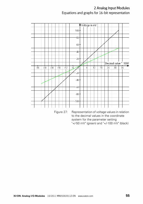
Figure 27: Representation of voltage values in relation to the decimal values in the coordinate system for the parameter setting "+/-50 mV" (green) and "+/-100 mV" (black)
XI/ON: Analog I/O-Modules 10/2011 MN05002011Z-EN www.eaton.com 55
2 Analog Input Modules
Equations and graphs for 16-bit representation
Representation of the voltage values in the range0 V DC…10 V DC
To use the equation below, the hexadecimal or binary value must be converted to a decimal value.
The hexadecimal/binary numerical value can be converted (using a pocket calculator) very simply to a decimal value since all the numbers are in the positive range of the two's complement (→ Figure 20 Page 39) of 16-bit values.
The value range:
0…10 V DC
is mapped to the number range:
0000hex…7FFFhex (decimal: 0…32767)
Once the decimal value has been determined, the voltage values can be calculated with the following equation:
voltage 3.05185 10 4– V× dezimal value×=
56 XI/ON: Analog I/O-Modules 10/2011 MN05002011Z-EN www.eaton.com

2 Analog Input Modules
Equations and graphs for 16-bit representation
Figure 28: Representation of voltage values in relation to the decimal values in the coordinate system
XI/ON: Analog I/O-Modules 10/2011 MN05002011Z-EN www.eaton.com 57
2 Analog Input Modules
Equations and graphs for 16-bit representation
Representation of the voltage values in the range-10 V DC…10 V DC
To use the equation below, the hexadecimal or binary value must be converted to a decimal value.
The hexadecimal/binary numerical values for the negative number range cannot be simply converted (using a pocket calculator) to a decimal value since the numbers are coded in the two's complement notation (→ Figure 20 Page 39).
All numerical values in the range 0000…7FFFhex represent positive numerical values in two's complement notation. Numbers in this range can be converted to a decimal value with a pocket calculator. This applies also to binary numbers with 0 as the most significant bit (bit 16).
All numerical values in the range 8000…FFFFhex represent negative values in two's complement notation. This applies also to binary numbers with 1 as the most significant bit (bit 16). The conver-sion to a decimal value shows: → “Example of the calculation of negative numerical values” Page 60.
The value range:
-10…-3.052 10-4 V DC
is mapped to the number range:
8000hex…FFFFhex (decimal:-32768…-1)
58 XI/ON: Analog I/O-Modules 10/2011 MN05002011Z-EN www.eaton.com
2 Analog Input Modules
Equations and graphs for 16-bit representation
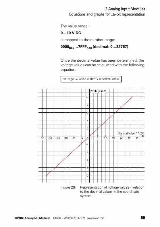
The value range:
0…10 V DC
is mapped to the number range:
0000hex…7FFFhex (decimal: 0…32767)
Once the decimal value has been determined, the voltage values can be calculated with the following equation:
Figure 29: Representation of voltage values in relation to the decimal values in the coordinate system
voltage 3.052 10 4– V× dezimal value×=
XI/ON: Analog I/O-Modules 10/2011 MN05002011Z-EN www.eaton.com 59
2 Analog Input Modules
Equations and graphs for 16-bit representation
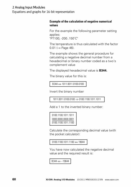
Example of the calculation of negative numerical values
For the example the following parameter setting applies:"PT100, -200..150’C"
The temperature is thus calculated with the factor 0.01 (→ Page 46).
The example shows the general procedure for calculating a negative decimal number from a hexadecimal or binary number coded as a two's complement value
The displayed hexadecimal value is B344.
The binary value for this is:
Invert the binary number
Add a 1 to the inverted binary number:
Calculate the corresponding decimal value (with the pocket calculator):
You have now calculated the negative decimal value and the required result is:
B344 1011.0011.0100.0100⇔
1011.0011.0100.0100 0100.1100.1011.1011
0100.1100.1011.1011
0000.0000.0000.00010100.1100.1011.1100----------------------------------------------
0100.1100.1011.1100 19644⇔
B344 19644–⇔
60 XI/ON: Analog I/O-Modules 10/2011 MN05002011Z-EN www.eaton.com
2 Analog Input Modules
Equations and graphs for 16-bit representation
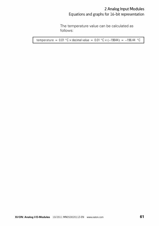
The temperature value can be calculated as follows:
temperature 0.01 °C decimal value× 0.01 °C 19644–( )× 196.44 °C–= = =
XI/ON: Analog I/O-Modules 10/2011 MN05002011Z-EN www.eaton.com 61
2 Analog Input Modules
Equations and graphs for 12-bit representation
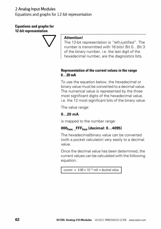
Equations and graphs for 12-bit representation
Representation of the current values in the range0…20 mA
To use the equation below, the hexadecimal or binary value must be converted to a decimal value. The numerical value is represented by the three most significant digits of the hexadecimal value, i.e. the 12 most significant bits of the binary value.
The value range:
0…20 mA
is mapped to the number range:
000hex…FFFhex (decimal: 0…4095)
The hexadecimal/binary value can be converted (with a pocket calculator) very easily to a decimal value.
Once the decimal value has been determined, the current values can be calculated with the following equation:
Attention!The 12-bit representation is “left-justified”. The number is transmitted with 16 bits! Bit 0…Bit 3 of the binary number, i.e. the last digit of the hexadecimal number, are the diagnostics bits.
current 4.88 10 3– mA× dezimal value×=
62 XI/ON: Analog I/O-Modules 10/2011 MN05002011Z-EN www.eaton.com
2 Analog Input Modules
Equations and graphs for 12-bit representation
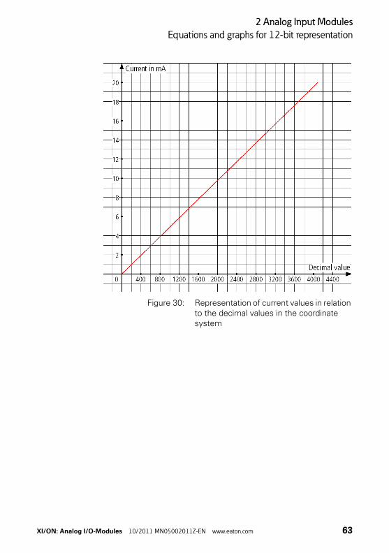
Figure 30: Representation of current values in relation to the decimal values in the coordinate system
XI/ON: Analog I/O-Modules 10/2011 MN05002011Z-EN www.eaton.com 63
2 Analog Input Modules
Equations and graphs for 12-bit representation
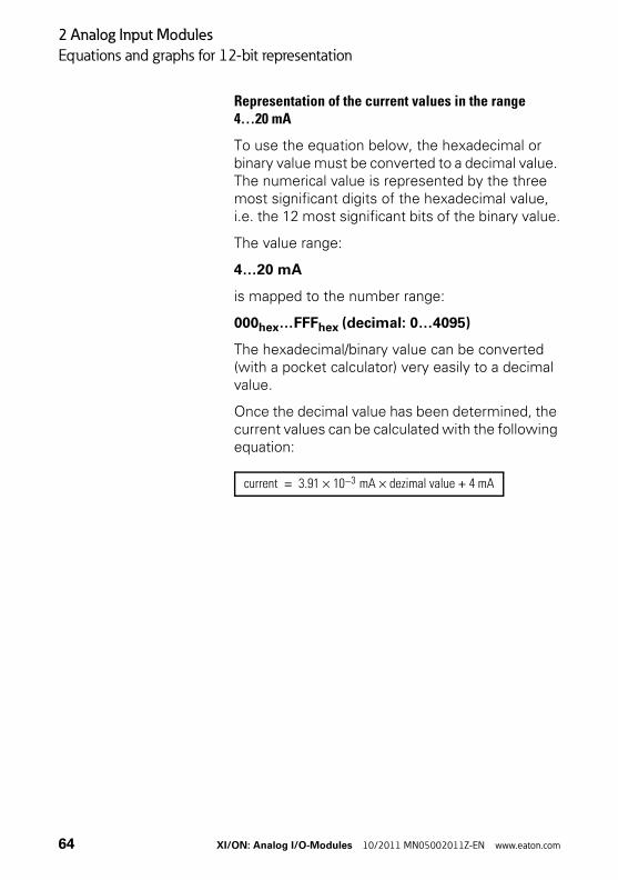
Representation of the current values in the range4…20 mA
To use the equation below, the hexadecimal or binary value must be converted to a decimal value. The numerical value is represented by the three most significant digits of the hexadecimal value, i.e. the 12 most significant bits of the binary value.
The value range:
4…20 mA
is mapped to the number range:
000hex…FFFhex (decimal: 0…4095)
The hexadecimal/binary value can be converted (with a pocket calculator) very easily to a decimal value.
Once the decimal value has been determined, the current values can be calculated with the following equation:
current 3.91 10 3– mA× dezimal value 4 mA+×=
64 XI/ON: Analog I/O-Modules 10/2011 MN05002011Z-EN www.eaton.com
2 Analog Input Modules
Equations and graphs for 12-bit representation
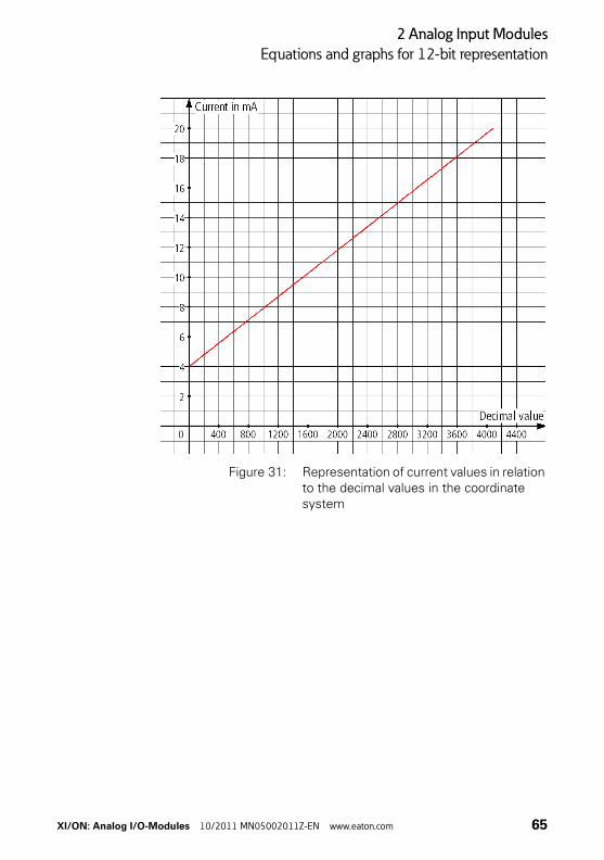
Figure 31: Representation of current values in relation to the decimal values in the coordinate system
XI/ON: Analog I/O-Modules 10/2011 MN05002011Z-EN www.eaton.com 65
2 Analog Input Modules
Equations and graphs for 12-bit representation
Representation of temperature values andresistance values for the XN-2AI-PT/NI-2/3
To use the equations below, the hexadecimal or binary value must be converted to a decimal value. The numerical value is represented by the three most significant digits of the hexadecimal value, i.e. the 12 most significant bits of the binary value (left-justified representation).
The hexadecimal/binary numerical values for the negative number range cannot be converted (using a pocket calculator) easily to a decimal value since the numbers are coded in the two's comple-ment notation (→ Figure 20 Page 39).
All numerical values in the range 000…7FFhex are positive values in two's complement notation. Numbers in this range can be converted to a decimal value with a pocket calculator. This applies also to binary numbers with 0 as the most significant bit (bit 16).
All numerical value in the range 800…FFFhex are negative values in two's complement notation. This applies also to binary numbers with 1 as the most significant bit (bit 12).
The following example shows the conversion to a decimal number: → “Example of the calculation of negative numerical values” Page 60.
Only the three most significant hexadecimal digits, i.e. the 12 most significant binary digits, are used for the calculation!
66 XI/ON: Analog I/O-Modules 10/2011 MN05002011Z-EN www.eaton.com
2 Analog Input Modules
Equations and graphs for 12-bit representation
Once the decimal value has been determined, the temperature values can be calculated according to the parameters defined.
The first equation is for the parameter setting:
• "PT100, -200..850’C"
• "NI100, -60..250’C"
• "PT200, -200..850’C"
• "PT500, -200..850’C"
• "PT1000, -200..850’C"
• "NI1000, -60..250’C"
The value range:
-200…-0.5 °C
is mapped to the number range:
E70hex…FFFhex (decimal: -400…-1)
The value range:
0…850 °C
is mapped to the number range:
000hex…6A4hex (decimal: 0…1700)
temperature 0.5 °C dezimal value×=
XI/ON: Analog I/O-Modules 10/2011 MN05002011Z-EN www.eaton.com 67
2 Analog Input Modules
Equations and graphs for 12-bit representation
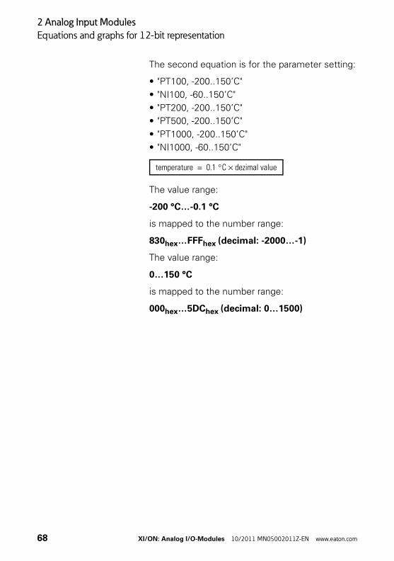
The second equation is for the parameter setting:
• "PT100, -200..150’C"
• "NI100, -60..150’C"
• "PT200, -200..150’C"
• "PT500, -200..150’C"
• "PT1000, -200..150’C"
• "NI1000, -60..150’C"
The value range:
-200 °C…-0.1 °C
is mapped to the number range:
830hex…FFFhex (decimal: -2000…-1)
The value range:
0…150 °C
is mapped to the number range:
000hex…5DChex (decimal: 0…1500)
temperature 0.1 °C dezimal value×=
68 XI/ON: Analog I/O-Modules 10/2011 MN05002011Z-EN www.eaton.com
2 Analog Input Modules
Equations and graphs for 12-bit representation
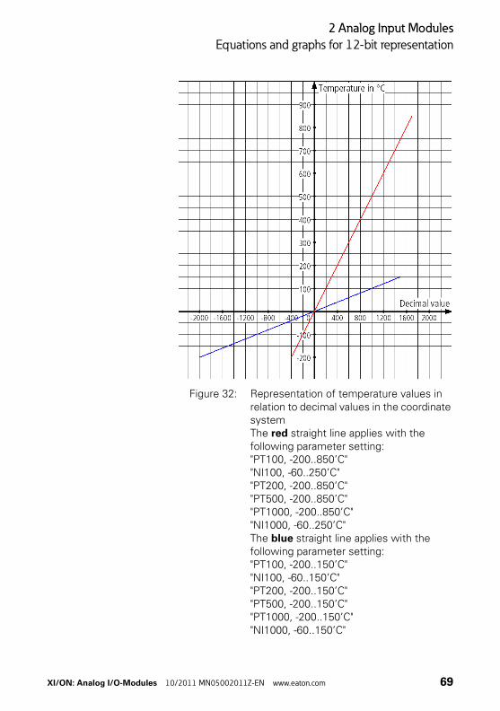
Figure 32: Representation of temperature values in relation to decimal values in the coordinate systemThe red straight line applies with the following parameter setting:"PT100, -200..850’C""NI100, -60..250’C""PT200, -200..850’C""PT500, -200..850’C""PT1000, -200..850’C""NI1000, -60..250’C"The blue straight line applies with the following parameter setting:"PT100, -200..150’C""NI100, -60..150’C""PT200, -200..150’C""PT500, -200..150’C""PT1000, -200..150’C""NI1000, -60..150’C"
XI/ON: Analog I/O-Modules 10/2011 MN05002011Z-EN www.eaton.com 69
2 Analog Input Modules
Equations and graphs for 12-bit representation
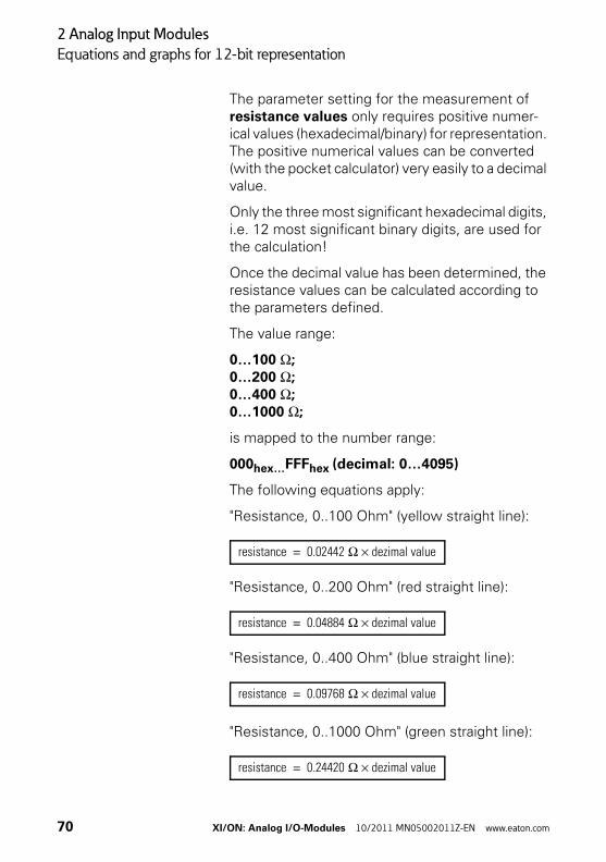
The parameter setting for the measurement of resistance values only requires positive numer-ical values (hexadecimal/binary) for representation. The positive numerical values can be converted (with the pocket calculator) very easily to a decimal value.
Only the three most significant hexadecimal digits, i.e. 12 most significant binary digits, are used for the calculation!
Once the decimal value has been determined, the resistance values can be calculated according to the parameters defined.
The value range:
0…100 Ω;0…200 Ω;0…400 Ω;0…1000 Ω;
is mapped to the number range:
000hex…FFFhex (decimal: 0…4095)
The following equations apply:
"Resistance, 0..100 Ohm" (yellow straight line):
"Resistance, 0..200 Ohm" (red straight line):
"Resistance, 0..400 Ohm" (blue straight line):
"Resistance, 0..1000 Ohm" (green straight line):
resistance 0.02442 Ω dezimal value×=
resistance 0.04884 Ω dezimal value×=
resistance 0.09768 Ω dezimal value×=
resistance 0.24420 Ω dezimal value×=
70 XI/ON: Analog I/O-Modules 10/2011 MN05002011Z-EN www.eaton.com
2 Analog Input Modules
Equations and graphs for 12-bit representation
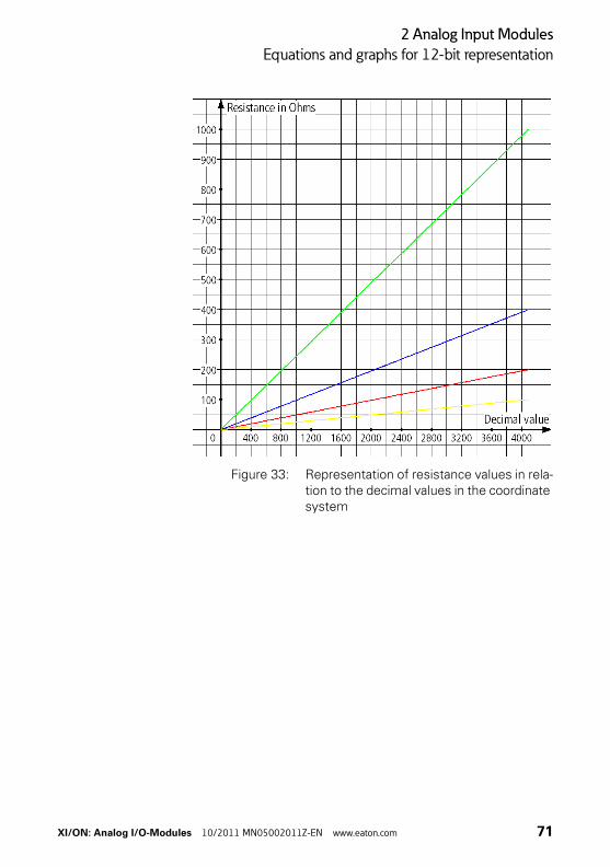
Figure 33: Representation of resistance values in rela-tion to the decimal values in the coordinate system
XI/ON: Analog I/O-Modules 10/2011 MN05002011Z-EN www.eaton.com 71
2 Analog Input Modules
Equations and graphs for 12-bit representation
Representation of temperature and voltagevalues for the XN-2AI-THERMO-PI
To use the equations below, the hexadecimal or binary value must be converted to a decimal value. The numerical value is represented by the three most significant digits of the hexadecimal value, i.e. the 12 most significant bits of the binary value (left-justified representation).
The hexadecimal/binary numerical values for the negative number range cannot be converted (using a pocket calculator) easily to a decimal value since the numbers are coded in the two's comple-ment notation (→ Figure 20 Page 39).
All numerical values in the range 000…7FFhex are positive values in two's complement notation. Numbers in this range can be converted to a decimal value with a pocket calculator. This applies also to binary numbers with 0 as the most significant bit (bit 16).
All numerical value in the range 800…FFFhex are negative values in two's complement notation. This applies also to binary numbers with 1 as the most significant bit (bit 12).
The following examples shows the conversion to a decimal number: → “Example of the calculation of negative numerical values” Page 60.
Only the three most significant hexadecimal digits, i.e. the 12 most significant binary digits, are used for the calculation!
72 XI/ON: Analog I/O-Modules 10/2011 MN05002011Z-EN www.eaton.com
2 Analog Input Modules
Equations and graphs for 12-bit representation
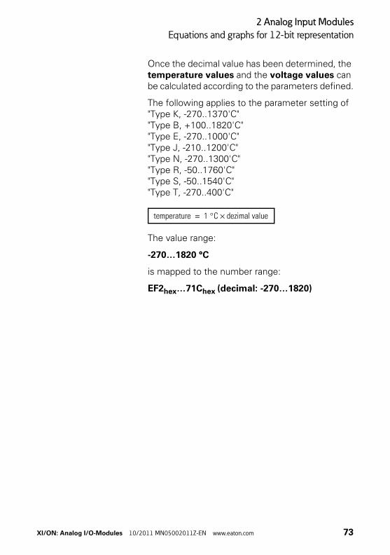
Once the decimal value has been determined, the temperature values and the voltage values can be calculated according to the parameters defined.
The following applies to the parameter setting of"Type K, -270..1370'C""Type B, +100..1820'C""Type E, -270..1000'C""Type J, -210..1200'C""Type N, -270..1300'C""Type R, -50..1760'C""Type S, -50..1540'C""Type T, -270..400'C"
The value range:
-270…1820 °C
is mapped to the number range:
EF2hex…71Chex (decimal: -270…1820)
temperature 1 °C dezimal value×=
XI/ON: Analog I/O-Modules 10/2011 MN05002011Z-EN www.eaton.com 73
2 Analog Input Modules
Equations and graphs for 12-bit representation
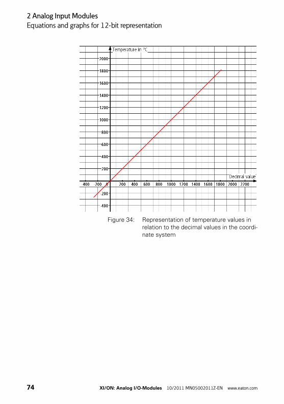
Figure 34: Representation of temperature values in relation to the decimal values in the coordi-nate system
74 XI/ON: Analog I/O-Modules 10/2011 MN05002011Z-EN www.eaton.com
2 Analog Input Modules
Equations and graphs for 12-bit representation
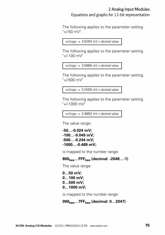
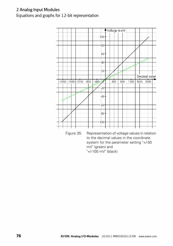
The following applies to the parameter setting "+/-50 mV":
The following applies to the parameter setting "+/-100 mV"
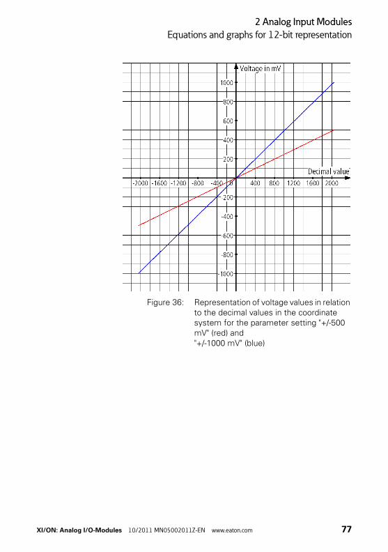
The following applies to the parameter setting "+/-500 mV"
The following applies to the parameter setting "+/-1000 mV"
The value range:
-50…-0.024 mV;-100…-0.049 mV;-500…-0.244 mV;-1000…-0.489 mV;
is mapped to the number range:
800hex…FFFhex (decimal: -2048…-1)
The value range:
0…50 mV;0…100 mV;0…500 mV;0…1000 mV;
is mapped to the number range:
000hex…7FFhex (decimal: 0…2047)
voltage 0.02443 mV dezimal value×=
voltage 0.04885 mV dezimal value×=
voltage 0.24426 mV dezimal value×=
voltage 0.48852 mV dezimal value×=
XI/ON: Analog I/O-Modules 10/2011 MN05002011Z-EN www.eaton.com 75
2 Analog Input Modules
Equations and graphs for 12-bit representation
Figure 35: Representation of voltage values in relation to the decimal values in the coordinate system for the parameter setting "+/-50 mV" (green) and"+/-100 mV" (black)
76 XI/ON: Analog I/O-Modules 10/2011 MN05002011Z-EN www.eaton.com
2 Analog Input Modules
Equations and graphs for 12-bit representation
Figure 36: Representation of voltage values in relation to the decimal values in the coordinate system for the parameter setting "+/-500 mV" (red) and"+/-1000 mV" (blue)
XI/ON: Analog I/O-Modules 10/2011 MN05002011Z-EN www.eaton.com 77
2 Analog Input Modules
Equations and graphs for 12-bit representation
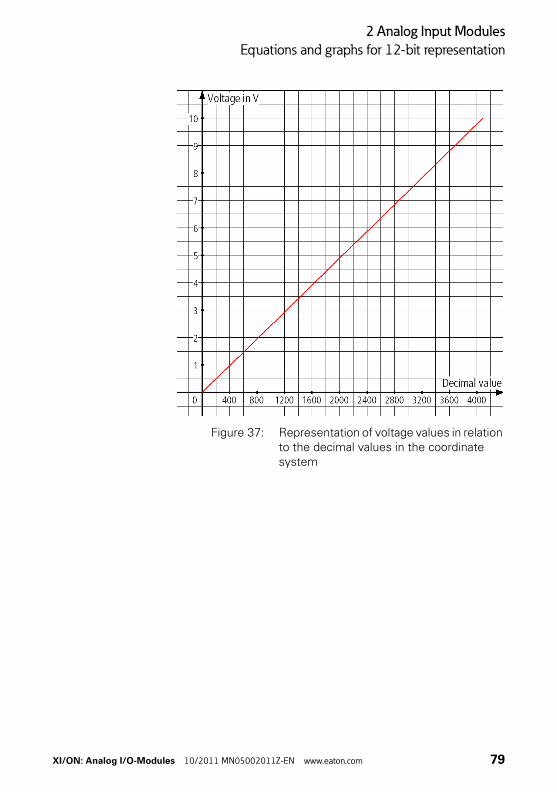
Representation of the voltage values in the range0 V DC…10 V DC
To use the equation below, the hexadecimal or binary value must be converted to a decimal value. The numerical value is represented by the three most significant digits of the hexadecimal value, i.e. the 12 most significant bits of the binary value (left-justified representation).
The hexadecimal/binary numerical value can be converted (using a pocket calculator) very easily to a decimal value since all the numbers are in the positive range of the two's complement (→ Figure 20 Page 39) of 12-bit values.
Once the decimal value has been determined, the voltage values can be calculated with the following equation:
The value range:
0…10 V DC
is mapped to the number range:
000hex…FFFhex (decimal: 0…4095)
voltage 0.002442 V dezimal value×=
78 XI/ON: Analog I/O-Modules 10/2011 MN05002011Z-EN www.eaton.com
2 Analog Input Modules
Equations and graphs for 12-bit representation
Figure 37: Representation of voltage values in relation to the decimal values in the coordinate system
XI/ON: Analog I/O-Modules 10/2011 MN05002011Z-EN www.eaton.com 79
2 Analog Input Modules
Equations and graphs for 12-bit representation
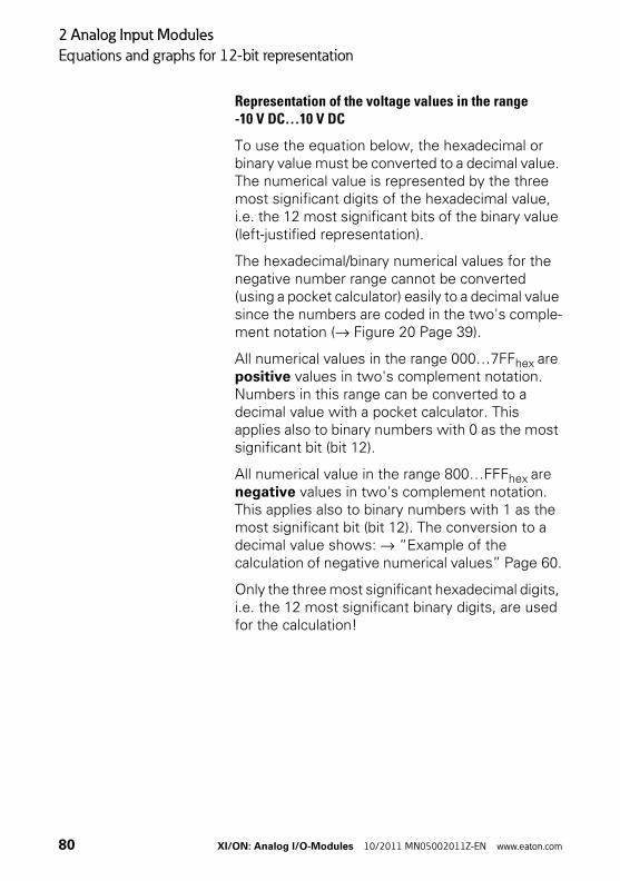
Representation of the voltage values in the range-10 V DC…10 V DC
To use the equation below, the hexadecimal or binary value must be converted to a decimal value. The numerical value is represented by the three most significant digits of the hexadecimal value, i.e. the 12 most significant bits of the binary value (left-justified representation).
The hexadecimal/binary numerical values for the negative number range cannot be converted (using a pocket calculator) easily to a decimal value since the numbers are coded in the two's comple-ment notation (→ Figure 20 Page 39).
All numerical values in the range 000…7FFhex are positive values in two's complement notation. Numbers in this range can be converted to a decimal value with a pocket calculator. This applies also to binary numbers with 0 as the most significant bit (bit 12).
All numerical value in the range 800…FFFhex are negative values in two's complement notation. This applies also to binary numbers with 1 as the most significant bit (bit 12). The conversion to a decimal value shows: → “Example of the calculation of negative numerical values” Page 60.
Only the three most significant hexadecimal digits, i.e. the 12 most significant binary digits, are used for the calculation!
80 XI/ON: Analog I/O-Modules 10/2011 MN05002011Z-EN www.eaton.com
2 Analog Input Modules
Equations and graphs for 12-bit representation
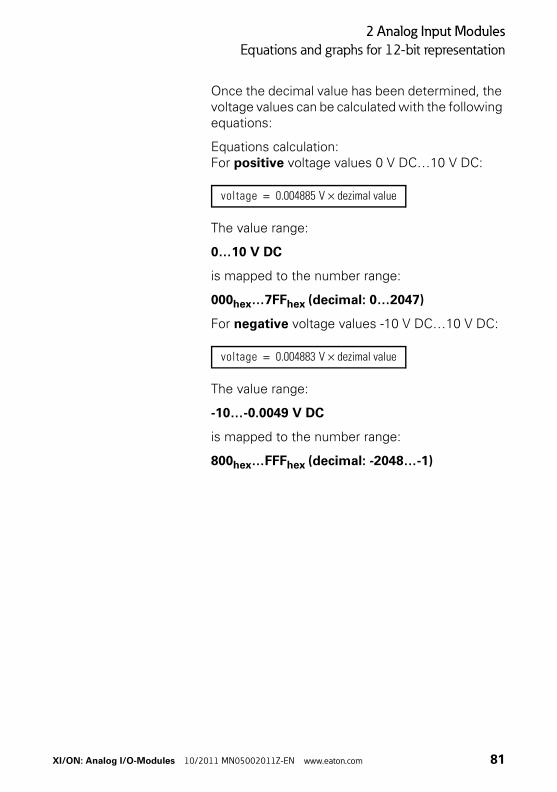
Once the decimal value has been determined, the voltage values can be calculated with the following equations:
Equations calculation:For positive voltage values 0 V DC…10 V DC:
The value range:
0…10 V DC
is mapped to the number range:
000hex…7FFhex (decimal: 0…2047)
For negative voltage values -10 V DC…10 V DC:
The value range:
-10…-0.0049 V DC
is mapped to the number range:
800hex…FFFhex (decimal: -2048…-1)
voltage 0.004885 V dezimal value×=
voltage 0.004883 V dezimal value×=
XI/ON: Analog I/O-Modules 10/2011 MN05002011Z-EN www.eaton.com 81
2 Analog Input Modules
Equations and graphs for 12-bit representation
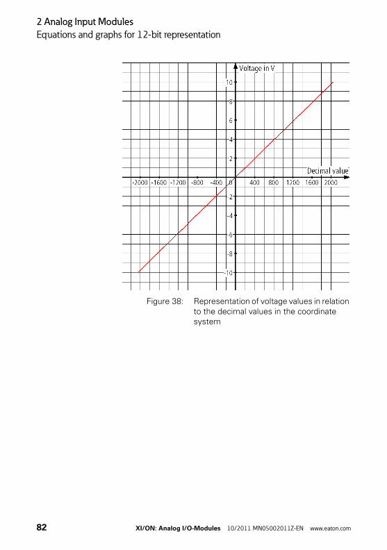
Figure 38: Representation of voltage values in relation to the decimal values in the coordinate system
82 XI/ON: Analog I/O-Modules 10/2011 MN05002011Z-EN www.eaton.com
2 Analog Input Modules
Equations and graphs for 12-bit representation
LEDs
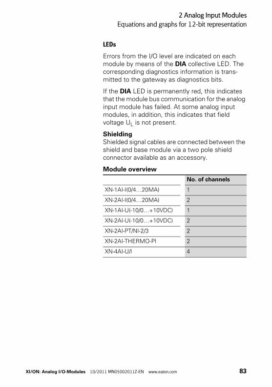
Errors from the I/O level are indicated on each module by means of the DIA collective LED. The corresponding diagnostics information is trans-mitted to the gateway as diagnostics bits.
If the DIA LED is permanently red, this indicates that the module bus communication for the analog input module has failed. At some analog input modules, in addition, this indicates that field voltage UL is not present.
ShieldingShielded signal cables are connected between the shield and base module via a two pole shield connector available as an accessory.
Module overview
No. of channels
XN-1AI-I(0/4…20MA) 1
XN-2AI-I(0/4…20MA) 2
XN-1AI-U(-10/0…+10VDC) 1
XN-2AI-U(-10/0…+10VDC) 2
XN-2AI-PT/NI-2/3 2
XN-2AI-THERMO-PI 2
XN-4AI-U/I 4
XI/ON: Analog I/O-Modules 10/2011 MN05002011Z-EN www.eaton.com 83
2 Analog Input Modules
XN-1AI-I(0/4…20MA)
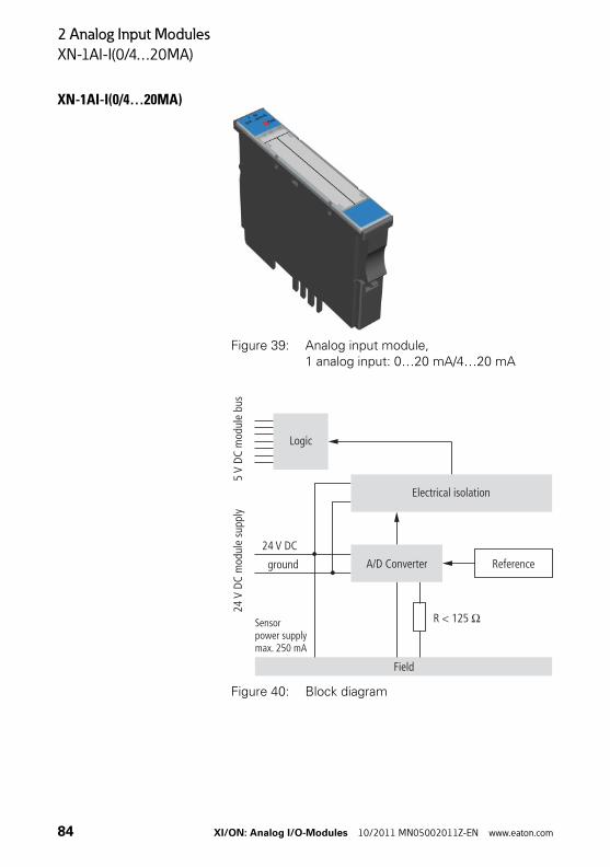
XN-1AI-I(0/4…20MA)
Figure 39: Analog input module, 1 analog input: 0…20 mA/4…20 mA
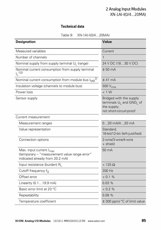
Figure 40: Block diagram
Logic
24V
DC m
odul
e su
pply
5m
odul
e bu
sV
DC
Electrical isolation
R < 125 O
Field
A/D Converter
Sensorpower supplymax. 250 mA
Reference
24 V DC
ground
84 XI/ON: Analog I/O-Modules 10/2011 MN05002011Z-EN www.eaton.com
2 Analog Input Modules
XN-1AI-I(0/4…20MA)
Technical data
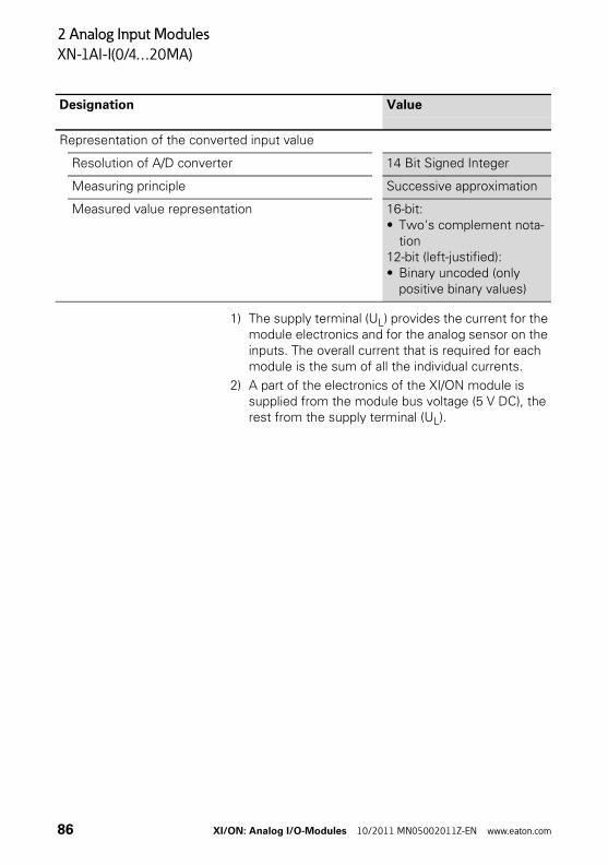
Table 9: XN-1AI-I(0/4…20MA)
Designation Value
Measured variables Current
Number of channels 1
Nominal supply from supply terminal UL (range) 24 V DC (18…30 V DC)
Nominal current consumption from supply terminal IL
1)2)≦ 50 mA
Nominal current consumption from module bus IMB2) ≦ 41 mA
Insulation voltage (channels to module bus) 500 Vrms
Power loss < 1 W
Sensor supply Bridged with the supply terminals UL and GNDL of the supply; not short-circuit-proof
Current measurement
Measurement ranges 0…20 mA/4…20 mA
Value representation Standard, 16-bit/12-bit (left-justified)
Connection options 2-wire/3-wire/4-wire + shield
Max. input current Imax (temporary – “measurement value range error” indicated already from 20.2 mA)
50 mA
Input resistance (burden) RL < 125 Ω
Cutoff frequency fG 200 Hz
Offset error < 0.1 %
Linearity (0.1…19.9 mA) 0.03 %
Basic error limit at 23 °C < 0.2 %
Repeatability 0.09 %
Temperature coefficient ≦ 300 ppm/ °C of limit value
XI/ON: Analog I/O-Modules 10/2011 MN05002011Z-EN www.eaton.com 85
2 Analog Input Modules
XN-1AI-I(0/4…20MA)
1) The supply terminal (UL) provides the current for the module electronics and for the analog sensor on the inputs. The overall current that is required for each module is the sum of all the individual currents.
2) A part of the electronics of the XI/ON module is supplied from the module bus voltage (5 V DC), the rest from the supply terminal (UL).
Representation of the converted input value
Resolution of A/D converter 14 Bit Signed Integer
Measuring principle Successive approximation
Measured value representation 16-bit:• Two's complement nota-
tion12-bit (left-justified):• Binary uncoded (only
positive binary values)
Designation Value
86 XI/ON: Analog I/O-Modules 10/2011 MN05002011Z-EN www.eaton.com
2 Analog Input Modules
XN-1AI-I(0/4…20MA)
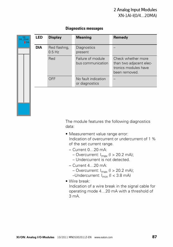
Diagnostics messages
The module features the following diagnostics data:
• Measurement value range error:Indication of overcurrent or undercurrent of 1 % of the set current range.
– Current 0…20 mA:– Overcurrent: Imax (I > 20.2 mA);– Undercurrent is not detected.
– Current 4…20 mA:– Overcurrent: Imax (I > 20.2 mA);–Undercurrent: Imin (I < 3.8 mA)
• Wire break:Indication of a wire break in the signal cable for operating mode 4…20 mA with a threshold of 3 mA.
LED Display Meaning Remedy
DIA Red flashng, 0.5 Hz
Diagnostics present
–
Red Failure of module bus communication
Check whether more than two adjacent elec-tronics modules have been removed.
OFF No fault indication or diagnostics
–
1AI0/4...20mA
DIA
XI/ON: Analog I/O-Modules 10/2011 MN05002011Z-EN www.eaton.com 87
2 Analog Input Modules
XN-1AI-I(0/4…20MA)
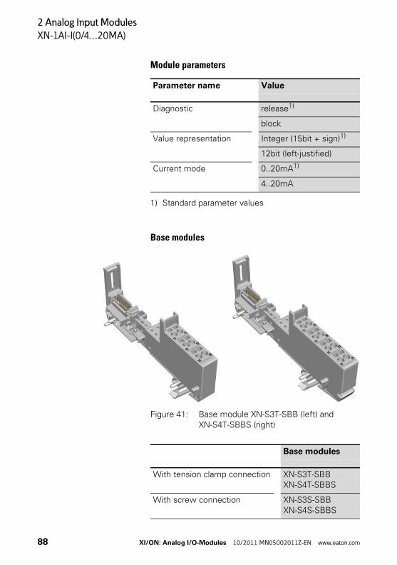
Module parameters
1) Standard parameter values
Base modules
Figure 41: Base module XN-S3T-SBB (left) and XN-S4T-SBBS (right)
Parameter name Value
Diagnostic release1)
block
Value representation Integer (15bit + sign)1)
12bit (left-justified)
Current mode 0..20mA1)
4..20mA
Base modules
With tension clamp connection XN-S3T-SBBXN-S4T-SBBS
With screw connection XN-S3S-SBBXN-S4S-SBBS
88 XI/ON: Analog I/O-Modules 10/2011 MN05002011Z-EN www.eaton.com
2 Analog Input Modules
XN-1AI-I(0/4…20MA)
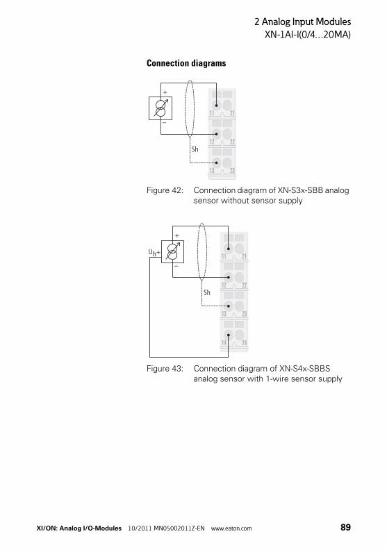
Connection diagrams
Figure 42: Connection diagram of XN-S3x-SBB analog sensor without sensor supply
Figure 43: Connection diagram of XN-S4x-SBBS analog sensor with 1-wire sensor supply
23
22
21
13
12
11
Sh
+
–
23
22
21
13
12
11
+
–
Uh+
Sh
2414
XI/ON: Analog I/O-Modules 10/2011 MN05002011Z-EN www.eaton.com 89
2 Analog Input Modules
XN-1AI-I(0/4…20MA)
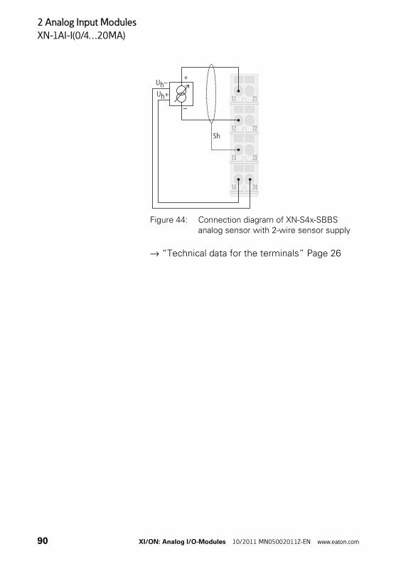
Figure 44: Connection diagram of XN-S4x-SBBS analog sensor with 2-wire sensor supply
→ “Technical data for the terminals” Page 26
23
22
21
13
12
11
+
–
Uh+
Uh–
Sh
2414
90 XI/ON: Analog I/O-Modules 10/2011 MN05002011Z-EN www.eaton.com
2 Analog Input Modules
XN-2AI-I(0/4…20MA)
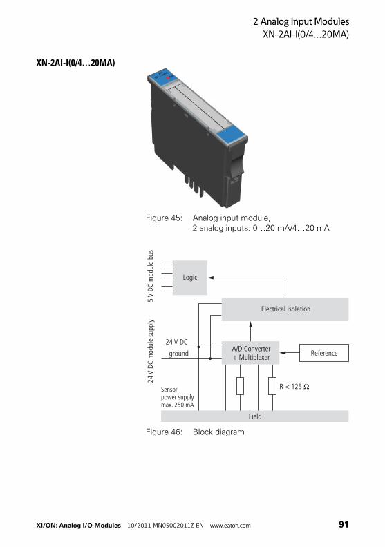
XN-2AI-I(0/4…20MA)
Figure 45: Analog input module, 2 analog inputs: 0…20 mA/4…20 mA
Figure 46: Block diagram
Logic
24V
DC m
odul
e su
pply
5m
odul
e bu
sV
DC
Electrical isolation
R < 125 O
Field
A/D Converter+ Multiplexer
Sensorpower supplymax. 250 mA
Reference
24 V DC
ground
XI/ON: Analog I/O-Modules 10/2011 MN05002011Z-EN www.eaton.com 91
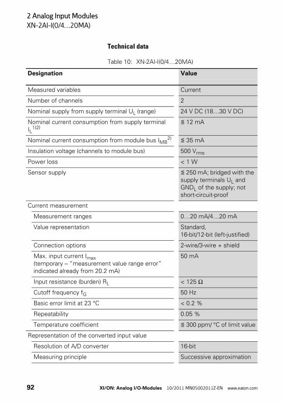
2 Analog Input Modules
XN-2AI-I(0/4…20MA)
Technical data
Table 10: XN-2AI-I(0/4…20MA)
Designation Value
Measured variables Current
Number of channels 2
Nominal supply from supply terminal UL (range) 24 V DC (18…30 V DC)
Nominal current consumption from supply terminal IL
1)2)≦ 12 mA
Nominal current consumption from module bus IMB2) ≦ 35 mA
Insulation voltage (channels to module bus) 500 Vrms
Power loss < 1 W
Sensor supply ≦ 250 mA; bridged with the supply terminals UL and GNDL of the supply; not short-circuit-proof
Current measurement
Measurement ranges 0…20 mA/4…20 mA
Value representation Standard, 16-bit/12-bit (left-justified)
Connection options 2-wire/3-wire + shield
Max. input current Imax (temporary – “measurement value range error” indicated already from 20.2 mA)
50 mA
Input resistance (burden) RL < 125 Ω
Cutoff frequency fG 50 Hz
Basic error limit at 23 °C < 0.2 %
Repeatability 0.05 %
Temperature coefficient ≦ 300 ppm/ °C of limit value
Representation of the converted input value
Resolution of A/D converter 16-bit
Measuring principle Successive approximation
92 XI/ON: Analog I/O-Modules 10/2011 MN05002011Z-EN www.eaton.com
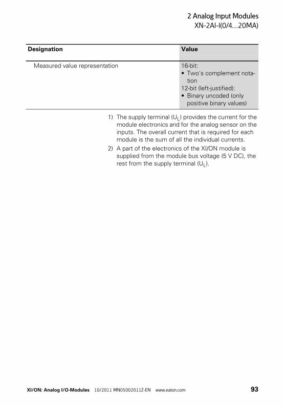
2 Analog Input Modules
XN-2AI-I(0/4…20MA)
1) The supply terminal (UL) provides the current for the module electronics and for the analog sensor on the inputs. The overall current that is required for each module is the sum of all the individual currents.
2) A part of the electronics of the XI/ON module is supplied from the module bus voltage (5 V DC), the rest from the supply terminal (UL).
Measured value representation 16-bit:• Two's complement nota-
tion12-bit (left-justified):• Binary uncoded (only
positive binary values)
Designation Value
XI/ON: Analog I/O-Modules 10/2011 MN05002011Z-EN www.eaton.com 93
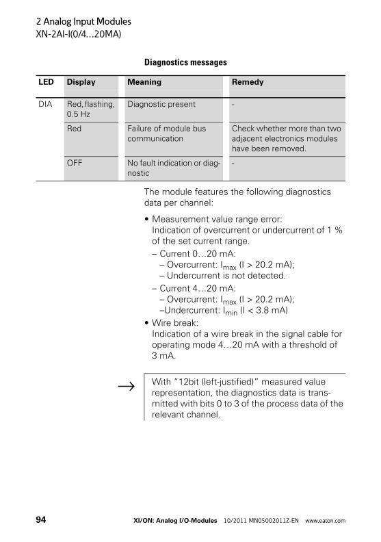
2 Analog Input Modules
XN-2AI-I(0/4…20MA)
Diagnostics messages
The module features the following diagnostics data per channel:
• Measurement value range error:Indication of overcurrent or undercurrent of 1 % of the set current range.
– Current 0…20 mA:– Overcurrent: Imax (I > 20.2 mA);– Undercurrent is not detected.
– Current 4…20 mA:– Overcurrent: Imax (I > 20.2 mA);–Undercurrent: Imin (I < 3.8 mA)
• Wire break:Indication of a wire break in the signal cable for operating mode 4…20 mA with a threshold of 3 mA.
LED Display Meaning Remedy
DIA Red, flashing, 0.5 Hz
Diagnostic present -
Red Failure of module bus communication
Check whether more than two adjacent electronics modules have been removed.
OFF No fault indication or diag-nostic
-
→ With “12bit (left-justified)” measured value representation, the diagnostics data is trans-mitted with bits 0 to 3 of the process data of the relevant channel.
94 XI/ON: Analog I/O-Modules 10/2011 MN05002011Z-EN www.eaton.com
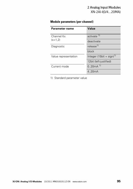
2 Analog Input Modules
XN-2AI-I(0/4…20MA)
Module parameters (per channel)
1) Standard parameter value
Parameter name Value
Channel Kx(x=1,2)
activate 1)
deactivate
Diagnostic release1)
block
Value representation Integer (15bit + sign)1)
12bit (left-justified)
Current mode 0..20mA 1)
4..20mA
XI/ON: Analog I/O-Modules 10/2011 MN05002011Z-EN www.eaton.com 95

2 Analog Input Modules
XN-2AI-I(0/4…20MA)
Base modules
Figure 47: Base module XN-S3T-SBB (left) and XN-S4T-SBBS (right)
Base modules
With tension clamp connection XN-S3T-SBBXN-S4T-SBBS
With screw connection XN-S3S-SBBXN-S4S-SBBS
96 XI/ON: Analog I/O-Modules 10/2011 MN05002011Z-EN www.eaton.com
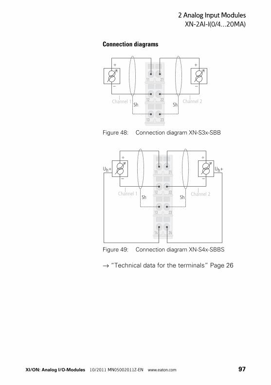
2 Analog Input Modules
XN-2AI-I(0/4…20MA)
Connection diagrams
Figure 48: Connection diagram XN-S3x-SBB
Figure 49: Connection diagram XN-S4x-SBBS
→ “Technical data for the terminals” Page 26
Channel 1 Channel 2
Channel 1 Channel 2
XI/ON: Analog I/O-Modules 10/2011 MN05002011Z-EN www.eaton.com 97

2 Analog Input Modules
XN-1AI-U(-10/0…+10VDC)
XN-1AI-U(-10/0…+10VDC)
Figure 50: Analog input module, 1 analog input: -10…+10 V DC/0…+10 V DC
Figure 51: Block diagram
Logic
24m
odul
e su
pply
V DC
5m
odul
e bu
sV
DC
Electrical isolation
R 98,5 kf O
Field
A/D Converter
-
max. 250 mA
Reference
24 V DC
ground
Sensor powersupply
98 XI/ON: Analog I/O-Modules 10/2011 MN05002011Z-EN www.eaton.com
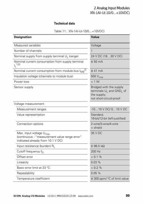
2 Analog Input Modules
XN-1AI-U(-10/0…+10VDC)
Technical data
Table 11: XN-1AI-U(-10/0…+10VDC)
Designation Value
Measured variables Voltage
Number of channels 1
Nominal supply from supply terminal UL (range) 24 V DC (18…30 V DC)
Nominal current consumption from supply terminal IL
1)2)≦ 50 mA
Nominal current consumption from module bus IMB2) ≦ 41 mA
Insulation voltage (channels to module bus) 500 Vrms
Power loss < 1 W
Sensor supply Bridged with the supply terminals UL and GNDL of the supply; not short-circuit-proof
Voltage measurement
Measurement ranges -10…10 V DC/ 0…10 V DC
Value representation Standard, 16-bit/12-bit (left-justified)
Connection options 2-wire/3-wire/4-wire + shield
Max. input voltage Umax(continuous - “measurement value range error” indicated already from 10.1 V DC)
35 V DC
Input resistance (burden) RL ≧ 98.5 kΩ
Cutoff frequency fG 200 Hz
Offset error < 0.1 %
Linearity 0.03 %
Basic error limit at 23 °C < 0.2 %
Repeatability 0.05 %
Temperature coefficient ≦ 300 ppm/ °C of limit value
XI/ON: Analog I/O-Modules 10/2011 MN05002011Z-EN www.eaton.com 99
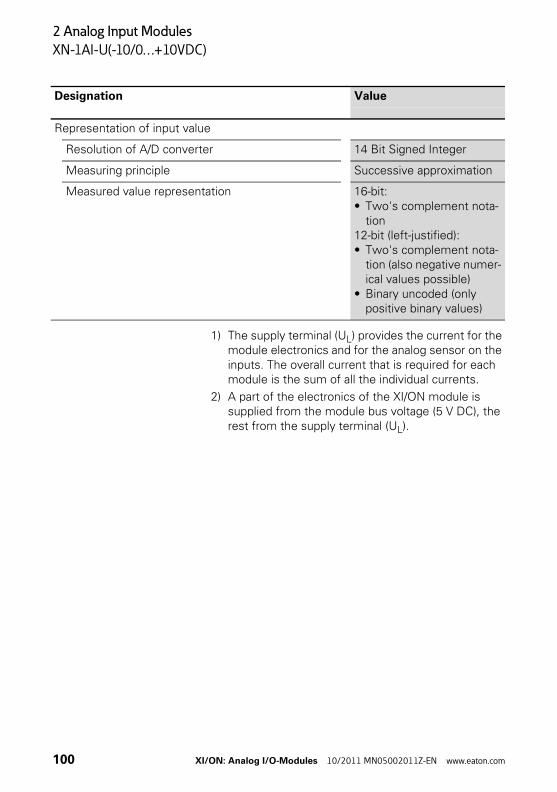
2 Analog Input Modules
XN-1AI-U(-10/0…+10VDC)
1) The supply terminal (UL) provides the current for the module electronics and for the analog sensor on the inputs. The overall current that is required for each module is the sum of all the individual currents.
2) A part of the electronics of the XI/ON module is supplied from the module bus voltage (5 V DC), the rest from the supply terminal (UL).
Representation of input value
Resolution of A/D converter 14 Bit Signed Integer
Measuring principle Successive approximation
Measured value representation 16-bit:• Two's complement nota-
tion12-bit (left-justified):• Two's complement nota-
tion (also negative numer-ical values possible)
• Binary uncoded (only positive binary values)
Designation Value
100 XI/ON: Analog I/O-Modules 10/2011 MN05002011Z-EN www.eaton.com
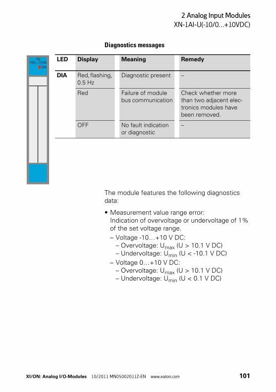
2 Analog Input Modules
XN-1AI-U(-10/0…+10VDC)
Diagnostics messages
The module features the following diagnostics data:
• Measurement value range error:Indication of overvoltage or undervoltage of 1% of the set voltage range.
– Voltage -10…+10 V DC:– Overvoltage: Umax (U > 10.1 V DC)– Undervoltage: Umin (U < -10.1 V DC)
– Voltage 0…+10 V DC:– Overvoltage: Umax (U > 10.1 V DC)– Undervoltage: Umin (U < 0.1 V DC)
LED Display Meaning Remedy
DIA Red, flashing, 0.5 Hz
Diagnostic present –
Red Failure of module bus communication
Check whether more than two adjacent elec-tronics modules have been removed.
OFF No fault indication or diagnostic
–
1AI-10/0...10Vdc
DIA
XI/ON: Analog I/O-Modules 10/2011 MN05002011Z-EN www.eaton.com 101

2 Analog Input Modules
XN-1AI-U(-10/0…+10VDC)
Module parameters
1) Standard parameter value
Base modules
Figure 52: Base module XN-S3T-SBB (left) and XN-S4T-SBBS (right)
Parameter name Value
Diagnostic release1)
block
Value representation Integer (15bit + sign)1)
12bit (left-justified)
Voltage mode -10..+10V
0..10V1)
Base modules
With tension clamp connection XN-S3T-SBBXN-S4T-SBBS
With screw connection XN-S3S-SBBXN-S4S-SBBS
102 XI/ON: Analog I/O-Modules 10/2011 MN05002011Z-EN www.eaton.com
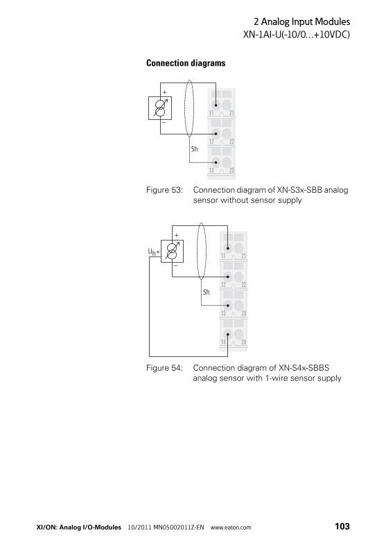
2 Analog Input Modules
XN-1AI-U(-10/0…+10VDC)
Connection diagrams
Figure 53: Connection diagram of XN-S3x-SBB analog sensor without sensor supply
Figure 54: Connection diagram of XN-S4x-SBBS analog sensor with 1-wire sensor supply
23
22
21
13
12
11
Sh
+
–
23
22
21
13
12
11
+
–
Uh+
Sh
2414
XI/ON: Analog I/O-Modules 10/2011 MN05002011Z-EN www.eaton.com 103
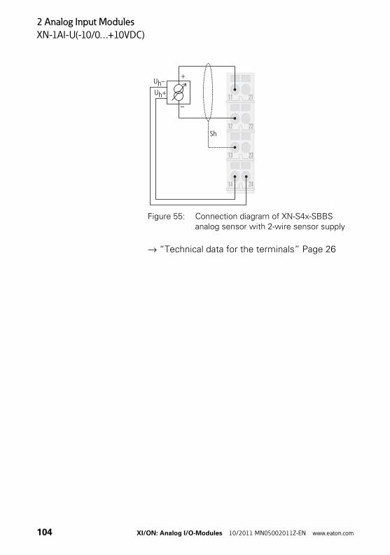
2 Analog Input Modules
XN-1AI-U(-10/0…+10VDC)
Figure 55: Connection diagram of XN-S4x-SBBS analog sensor with 2-wire sensor supply
→ “Technical data for the terminals” Page 26
23
22
21
13
12
11
+
–
Uh+
Uh–
Sh
2414
104 XI/ON: Analog I/O-Modules 10/2011 MN05002011Z-EN www.eaton.com

2 Analog Input Modules
XN-2AI-U(-10/0…+10VDC)
XN-2AI-U(-10/0…+10VDC)
Figure 56: Analog input module, 2 analog inputs: -10…+10 V DC/0…+10 V DC
Figure 57: Block diagram
Logic
24m
odul
e su
pply
V DC
5m
odul
e bu
sV
DC
Electrical isolation
R 98.5 kf O
Field
A/D Converter+ Multiplexer
Sensorpower supplymax. 250 mA
Reference
24 V DC
ground
XI/ON: Analog I/O-Modules 10/2011 MN05002011Z-EN www.eaton.com 105
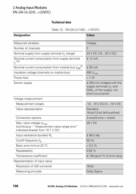
2 Analog Input Modules
XN-2AI-U(-10/0…+10VDC)
Technical data
Table 12: XN-2AI-U(-10/0…+10VDC)
Designation Value
Measured variables Voltage
Number of channels 2
Nominal supply from supply terminal UL (range) 24 V DC (18…30 V DC)
Nominal current consumption from supply terminal IL
1)2)≦ 12 mA
Nominal current consumption from module bus IMB2) ≦ 35 mA
Insulation voltage (channels to module bus) 500 Vrms
Power loss < 1 W
Sensor supply ≦ 250 mA; bridged with the supply terminals UL and GNDL of the supply; not short-circuit-proof
Voltage measurement
Measurement ranges -10…10 V DC/ 0…10 V DC
Value representation Standard, 16-bit/12-bit (left-justified)
Connection options 2-wire/3-wire + shield
Max. input voltage Umax(continuous - “measurement value range error” indicated already from 10.1 V DC)
35 V DC
Input resistance (burden) RL ≧ 98.5 kΩ
Cutoff frequency fG 50 Hz
Basic error limit at 23 °C < 0.2 %
Repeatability 0.05 %
Temperature coefficient ≦ 150 ppm/ °C of limit value
Representation of input value
Resolution of A/D converter 16-bit
Measuring principle Delta Sigma
106 XI/ON: Analog I/O-Modules 10/2011 MN05002011Z-EN www.eaton.com
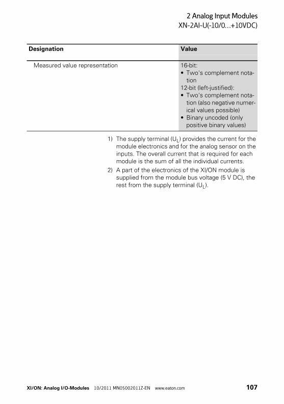
2 Analog Input Modules
XN-2AI-U(-10/0…+10VDC)
1) The supply terminal (UL) provides the current for the module electronics and for the analog sensor on the inputs. The overall current that is required for each module is the sum of all the individual currents.
2) A part of the electronics of the XI/ON module is supplied from the module bus voltage (5 V DC), the rest from the supply terminal (UL).
Measured value representation 16-bit:• Two's complement nota-
tion12-bit (left-justified):• Two's complement nota-
tion (also negative numer-ical values possible)
• Binary uncoded (only positive binary values)
Designation Value
XI/ON: Analog I/O-Modules 10/2011 MN05002011Z-EN www.eaton.com 107
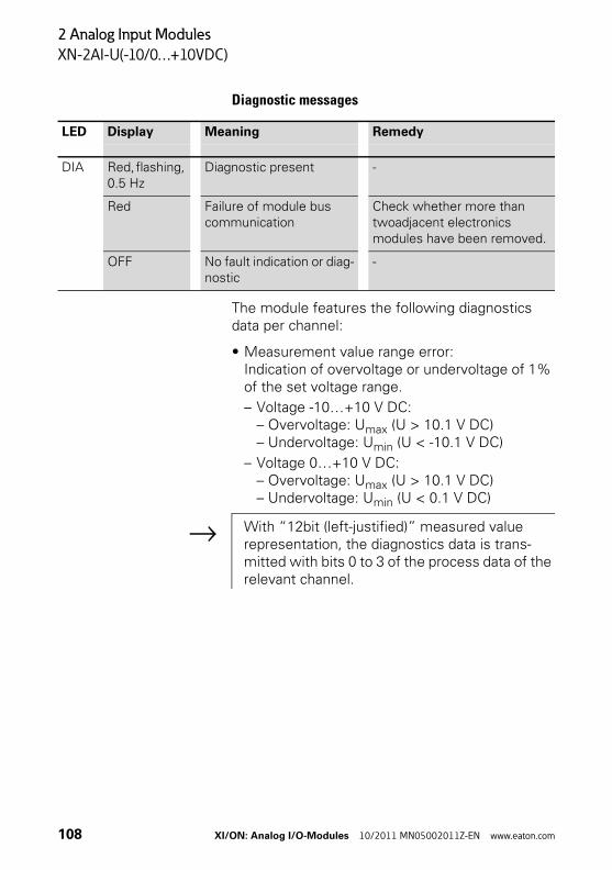
2 Analog Input Modules
XN-2AI-U(-10/0…+10VDC)
Diagnostic messages
The module features the following diagnostics data per channel:
• Measurement value range error:Indication of overvoltage or undervoltage of 1% of the set voltage range.
– Voltage -10…+10 V DC:– Overvoltage: Umax (U > 10.1 V DC)– Undervoltage: Umin (U < -10.1 V DC)
– Voltage 0…+10 V DC:– Overvoltage: Umax (U > 10.1 V DC)– Undervoltage: Umin (U < 0.1 V DC)
LED Display Meaning Remedy
DIA Red, flashing, 0.5 Hz
Diagnostic present -
Red Failure of module bus communication
Check whether more than twoadjacent electronics modules have been removed.
OFF No fault indication or diag-nostic
-
→ With “12bit (left-justified)” measured value representation, the diagnostics data is trans-mitted with bits 0 to 3 of the process data of the relevant channel.
108 XI/ON: Analog I/O-Modules 10/2011 MN05002011Z-EN www.eaton.com
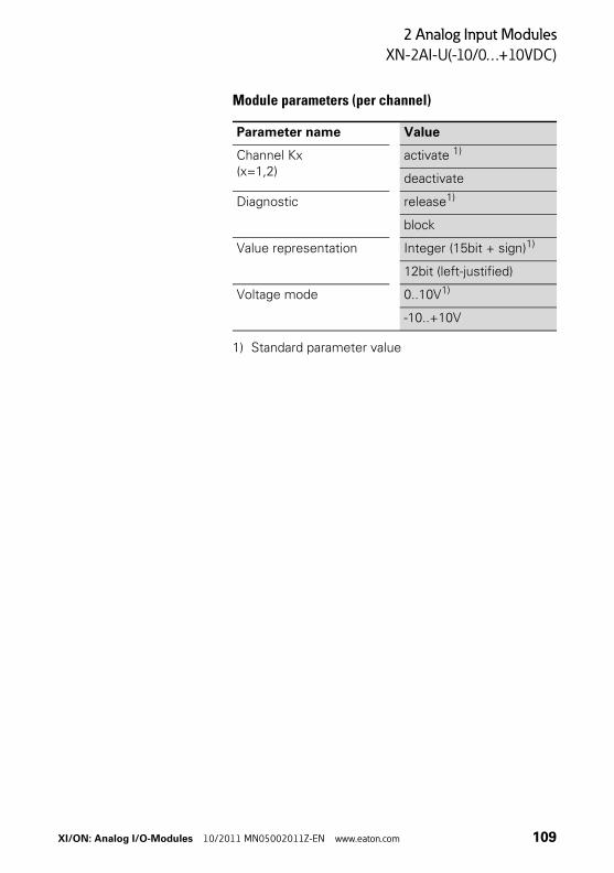
2 Analog Input Modules
XN-2AI-U(-10/0…+10VDC)
Module parameters (per channel)
1) Standard parameter value
Parameter name Value
Channel Kx(x=1,2)
activate 1)
deactivate
Diagnostic release1)
block
Value representation Integer (15bit + sign)1)
12bit (left-justified)
Voltage mode 0..10V1)
-10..+10V
XI/ON: Analog I/O-Modules 10/2011 MN05002011Z-EN www.eaton.com 109
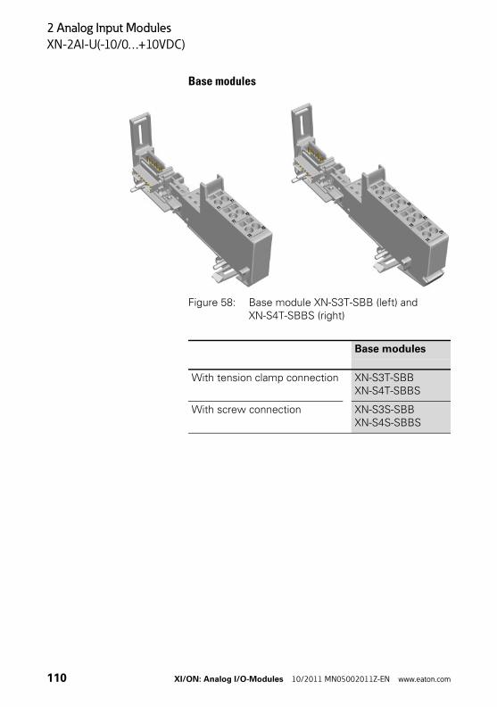
2 Analog Input Modules
XN-2AI-U(-10/0…+10VDC)
Base modules
Figure 58: Base module XN-S3T-SBB (left) and XN-S4T-SBBS (right)
Base modules
With tension clamp connection XN-S3T-SBBXN-S4T-SBBS
With screw connection XN-S3S-SBBXN-S4S-SBBS
110 XI/ON: Analog I/O-Modules 10/2011 MN05002011Z-EN www.eaton.com
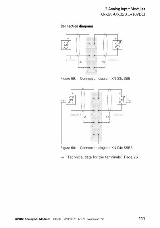
2 Analog Input Modules
XN-2AI-U(-10/0…+10VDC)
Connection diagrams
Figure 59: Connection diagram XN-S3x-SBB
Figure 60: Connection diagram XN-S4x-SBBS
→ “Technical data for the terminals” Page 26
Channel 1 Channel 2
Channel 1 Channel 2
XI/ON: Analog I/O-Modules 10/2011 MN05002011Z-EN www.eaton.com 111
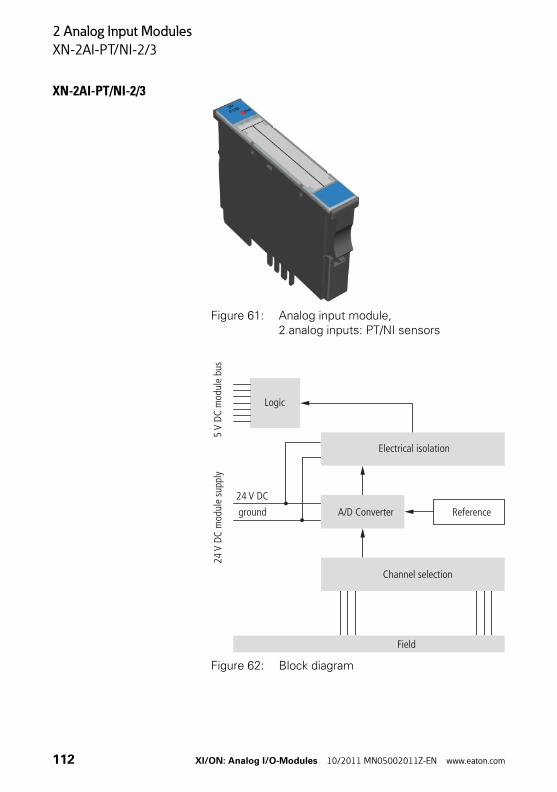
2 Analog Input Modules
XN-2AI-PT/NI-2/3
XN-2AI-PT/NI-2/3
Figure 61: Analog input module, 2 analog inputs: PT/NI sensors
Figure 62: Block diagram
Logic
24m
odul
e su
pply
V DC
5m
odul
e bu
sV
DC
Electrical isolation
Channel selection
Field
A/D Converter Reference
24 V DC
ground
112 XI/ON: Analog I/O-Modules 10/2011 MN05002011Z-EN www.eaton.com
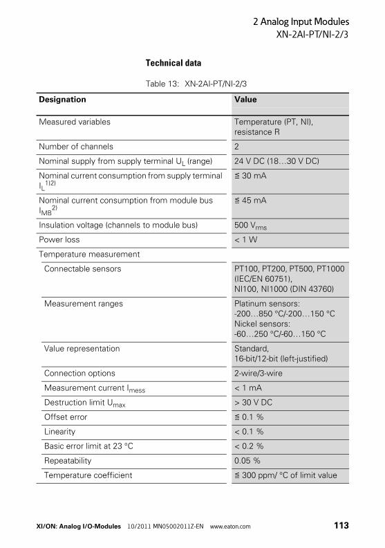
2 Analog Input Modules
XN-2AI-PT/NI-2/3
Technical data
Table 13: XN-2AI-PT/NI-2/3
Designation Value
Measured variables Temperature (PT, NI), resistance R
Number of channels 2
Nominal supply from supply terminal UL (range) 24 V DC (18…30 V DC)
Nominal current consumption from supply terminal IL
1)2)≦ 30 mA
Nominal current consumption from module bus IMB
2)≦ 45 mA
Insulation voltage (channels to module bus) 500 Vrms
Power loss < 1 W
Temperature measurement
Connectable sensors PT100, PT200, PT500, PT1000 (IEC/EN 60751), NI100, NI1000 (DIN 43760)
Measurement ranges Platinum sensors:-200…850 °C/-200…150 °CNickel sensors:-60…250 °C/-60…150 °C
Value representation Standard, 16-bit/12-bit (left-justified)
Connection options 2-wire/3-wire
Measurement current Imess < 1 mA
Destruction limit Umax > 30 V DC
Offset error ≦ 0.1 %
Linearity < 0.1 %
Basic error limit at 23 °C < 0.2 %
Repeatability 0.05 %
Temperature coefficient ≦ 300 ppm/ °C of limit value
XI/ON: Analog I/O-Modules 10/2011 MN05002011Z-EN www.eaton.com 113
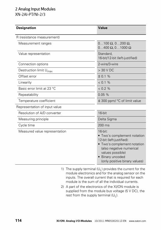
2 Analog Input Modules
XN-2AI-PT/NI-2/3
1) The supply terminal (UL) provides the current for the module electronics and for the analog sensor on the inputs. The overall current that is required for each module is the sum of all the individual currents.
2) A part of the electronics of the XI/ON module is supplied from the module bus voltage (5 V DC), the rest from the supply terminal (UL).
R (resistance measurement)
Measurement ranges 0…100 Ω, 0…200 Ω, 0…400 Ω, 0…1000 Ω
Value representation Standard, 16-bit/12-bit (left-justified)
Connection options 2-wire/3-wire
Destruction limit Umax > 30 V DC
Offset error ≦ 0.1 %
Linearity < 0.1 %
Basic error limit at 23 °C < 0.2 %
Repeatability 0.05 %
Temperature coefficient ≦ 300 ppm/ °C of limit value
Representation of input value
Resolution of A/D converter 16-bit
Measuring principle Delta Sigma
Cycle time 200 ms
Measured value representation 16-bit:• Two's complement notation12-bit (left-justified):• Two's complement notation
(also negative numerical values possible)
• Binary uncoded (only positive binary values)
Designation Value
114 XI/ON: Analog I/O-Modules 10/2011 MN05002011Z-EN www.eaton.com
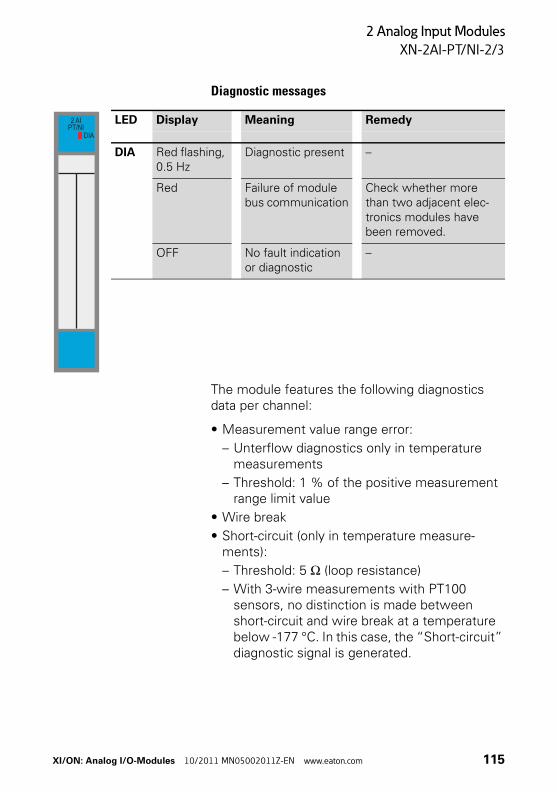
2 Analog Input Modules
XN-2AI-PT/NI-2/3
Diagnostic messages
The module features the following diagnostics data per channel:
• Measurement value range error:
– Unterflow diagnostics only in temperature measurements
– Threshold: 1 % of the positive measurement range limit value
• Wire break
• Short-circuit (only in temperature measure-ments):
– Threshold: 5 Ω (loop resistance)
– With 3-wire measurements with PT100 sensors, no distinction is made between short-circuit and wire break at a temperature below -177 °C. In this case, the “Short-circuit” diagnostic signal is generated.
LED Display Meaning Remedy
DIA Red flashing, 0.5 Hz
Diagnostic present –
Red Failure of module bus communication
Check whether more than two adjacent elec-tronics modules have been removed.
OFF No fault indication or diagnostic
–
2 AIPT/NI
DIA
XI/ON: Analog I/O-Modules 10/2011 MN05002011Z-EN www.eaton.com 115
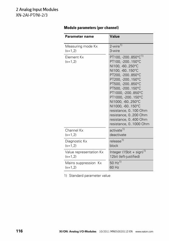
2 Analog Input Modules
XN-2AI-PT/NI-2/3
Module parameters (per channel)
1) Standard parameter value
Parameter name Value
Measuring mode Kx(x=1,2)
2-wire1)
3-wire
Element Kx(x=1,2)
PT100, -200..850°C1)
PT100, -200..150°CNI100, -60..250°CNI100, -60..150°CPT200, -200..850°CPT200, -200..150°CPT500, -200..850°CPT500, -200..150°CPT1000, -200..850°CPT1000, -200..150°CNI1000, -60..250°CNI1000, -60..150°Cresistance, 0..100 Ohmresistance, 0..200 Ohmresistance, 0..400 Ohmresistance, 0..1000 Ohm
Channel Kx(x=1,2)
activate1)
deactivate
Diagnostic Kx(x=1,2)
release1)
block
Value representation Kx(x=1,2)
Integer (15bit + sign)1)
12bit (left-justified)
Mains suppression Kx(x=1,2)
50 Hz1)
60 Hz
116 XI/ON: Analog I/O-Modules 10/2011 MN05002011Z-EN www.eaton.com
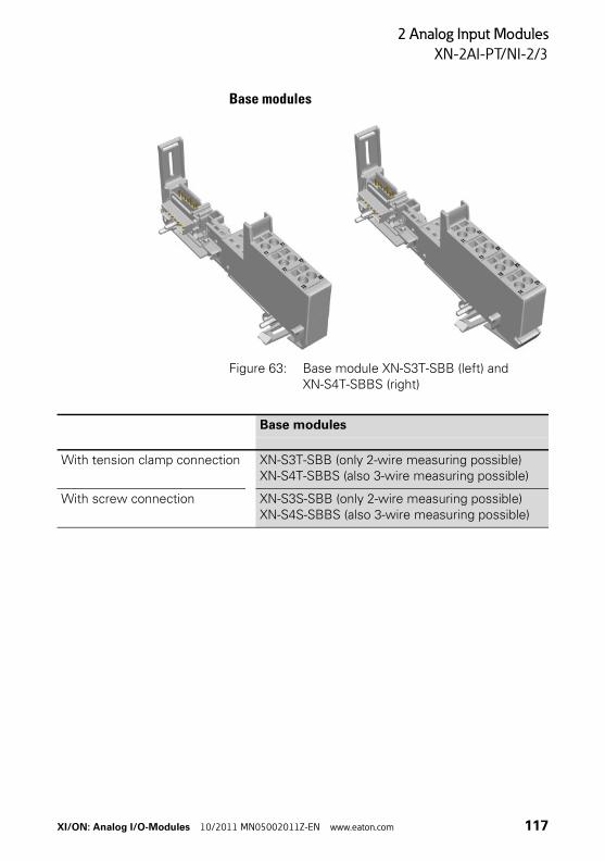
2 Analog Input Modules
XN-2AI-PT/NI-2/3
Base modules
Figure 63: Base module XN-S3T-SBB (left) and XN-S4T-SBBS (right)
Base modules
With tension clamp connection XN-S3T-SBB (only 2-wire measuring possible)XN-S4T-SBBS (also 3-wire measuring possible)
With screw connection XN-S3S-SBB (only 2-wire measuring possible)XN-S4S-SBBS (also 3-wire measuring possible)
XI/ON: Analog I/O-Modules 10/2011 MN05002011Z-EN www.eaton.com 117
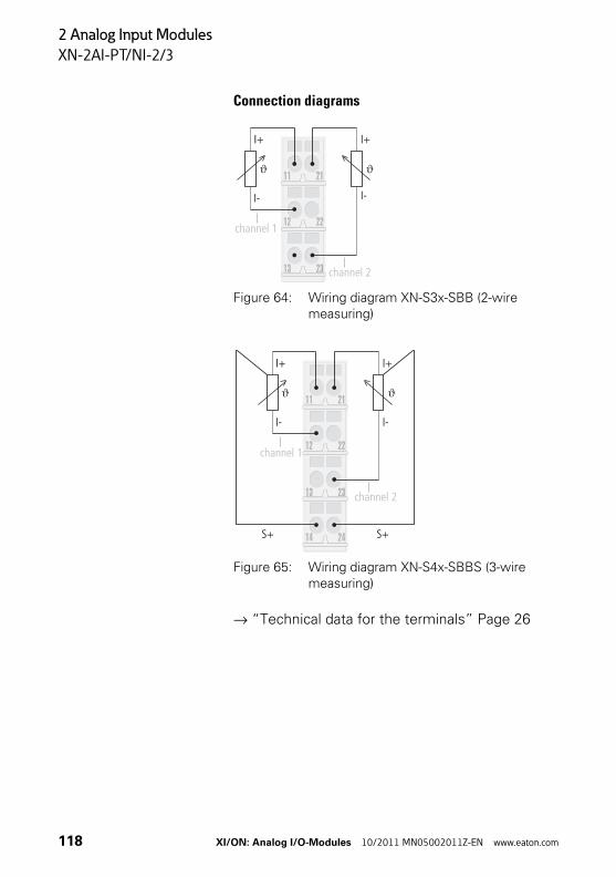
2 Analog Input Modules
XN-2AI-PT/NI-2/3
Connection diagrams
Figure 64: Wiring diagram XN-S3x-SBB (2-wire measuring)
Figure 65: Wiring diagram XN-S4x-SBBS (3-wire measuring)
→ “Technical data for the terminals” Page 26
channel 1
channel 2
channel 1
channel 2
118 XI/ON: Analog I/O-Modules 10/2011 MN05002011Z-EN www.eaton.com
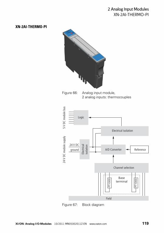
2 Analog Input Modules
XN-2AI-THERMO-PI
XN-2AI-THERMO-PI
Figure 66: Analog input module, 2 analog inputs: thermocouples
Figure 67: Block diagram
PT10
00
PT10
00
Logic
24m
odul
e su
ppl y
V DC
5m
odul
e bu
sV
DC
Electrical isolation
Field
A/D Converter Reference
Channel selection
Baseterminal
isola
tion24 V DC
ground
Elec
trica
l
XI/ON: Analog I/O-Modules 10/2011 MN05002011Z-EN www.eaton.com 119
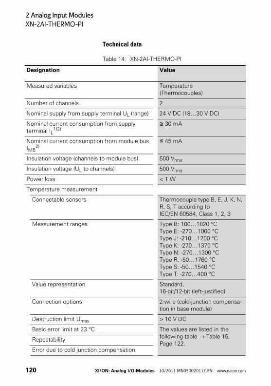
2 Analog Input Modules
XN-2AI-THERMO-PI
Technical data
Table 14: XN-2AI-THERMO-PI
Designation Value
Measured variables Temperature(Thermocouples)
Number of channels 2
Nominal supply from supply terminal UL (range) 24 V DC (18…30 V DC)
Nominal current consumption from supply terminal IL
1)2)≦ 30 mA
Nominal current consumption from module bus IMB
2)≦ 45 mA
Insulation voltage (channels to module bus) 500 Vrms
Insulation voltage (UL to channels) 500 Vrms
Power loss < 1 W
Temperature measurement
Connectable sensors Thermocouple type B, E, J, K, N, R, S, T according to IEC/EN 60584, Class 1, 2, 3
Measurement ranges Type B: 100…1820 °CType E: -270…1000 °CType J: -210…1200 °CType K: -270…1370 °CType N: -270…1300 °CType R: -50…1760 °CType S: -50…1540 °CType T: -270…400 °C
Value representation Standard, 16-bit/12-bit (left-justified)
Connection options 2-wire (cold-junction compensa-tion in base module)
Destruction limit Umax > 10 V DC
Basic error limit at 23 °C The values are listed in the following table → Table 15, Page 122.
Repeatability
Error due to cold junction compensation
120 XI/ON: Analog I/O-Modules 10/2011 MN05002011Z-EN www.eaton.com
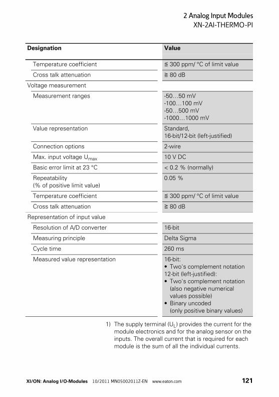
2 Analog Input Modules
XN-2AI-THERMO-PI
1) The supply terminal (UL) provides the current for the module electronics and for the analog sensor on the inputs. The overall current that is required for each module is the sum of all the individual currents.
Temperature coefficient ≦ 300 ppm/ °C of limit value
Cross talk attenuation ≧ 80 dB
Voltage measurement
Measurement ranges -50…50 mV-100…100 mV-50…500 mV-1000…1000 mV
Value representation Standard, 16-bit/12-bit (left-justified)
Connection options 2-wire
Max. input voltage Umax 10 V DC
Basic error limit at 23 °C < 0.2 % (normally)
Repeatability(% of positive limit value)
0.05 %
Temperature coefficient ≦ 300 ppm/ °C of limit value
Cross talk attenuation ≧ 80 dB
Representation of input value
Resolution of A/D converter 16-bit
Measuring principle Delta Sigma
Cycle time 260 ms
Measured value representation 16-bit:• Two's complement notation12-bit (left-justified):• Two's complement notation
(also negative numerical values possible)
• Binary uncoded (only positive binary values)
Designation Value
XI/ON: Analog I/O-Modules 10/2011 MN05002011Z-EN www.eaton.com 121
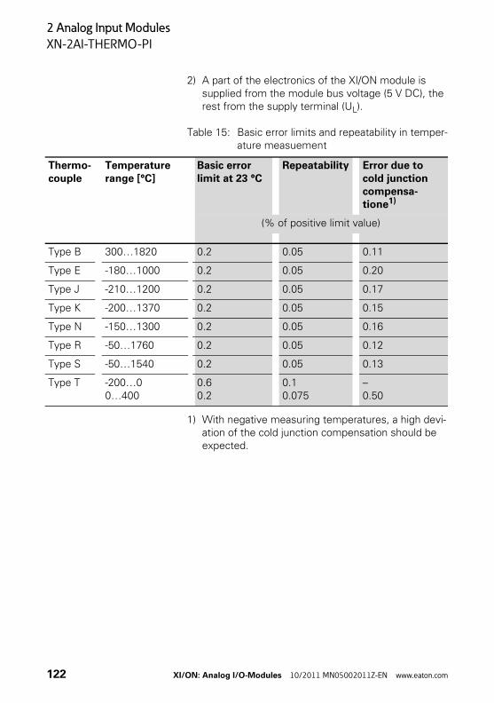
2 Analog Input Modules
XN-2AI-THERMO-PI
2) A part of the electronics of the XI/ON module is supplied from the module bus voltage (5 V DC), the rest from the supply terminal (UL).
Table 15: Basic error limits and repeatability in temper-ature measuement
1) With negative measuring temperatures, a high devi-ation of the cold junction compensation should be expected.
Thermo-couple
Temperature range [°C]
Basic error limit at 23 °C
Repeatability Error due to cold junction compensa-tione1)
(% of positive limit value)
Type B 300…1820 0.2 0.05 0.11
Type E -180…1000 0.2 0.05 0.20
Type J -210…1200 0.2 0.05 0.17
Type K -200…1370 0.2 0.05 0.15
Type N -150…1300 0.2 0.05 0.16
Type R -50…1760 0.2 0.05 0.12
Type S -50…1540 0.2 0.05 0.13
Type T -200…00…400
0.60.2
0.10.075
–0.50
122 XI/ON: Analog I/O-Modules 10/2011 MN05002011Z-EN www.eaton.com
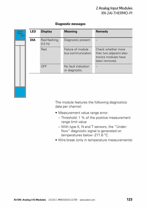
2 Analog Input Modules
XN-2AI-THERMO-PI
Diagnostic messages
The module features the following diagnostics data per channel:
• Measurement value range error:
– Threshold: 1 % of the positive measurement range limit value
– With type K, N and T sensors, the “Under-flow” diagnostic signal is generated on temperatures below -271.6 °C.
• Wire break (only in temperature measurements)
LED Display Meaning Remedy
DIA Red flashing, 0.5 Hz
Diagnostic present –
Red Failure of module bus communication
Check whether more than two adjacent elec-tronics modules have been removed.
OFF No fault indication or diagnostic
–
2 AI PIThermo
DIA
XI/ON: Analog I/O-Modules 10/2011 MN05002011Z-EN www.eaton.com 123
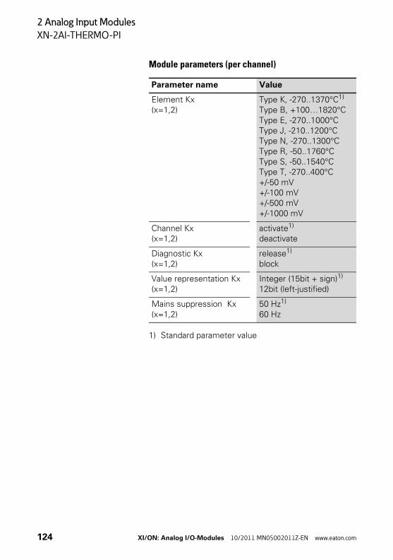
2 Analog Input Modules
XN-2AI-THERMO-PI
Module parameters (per channel)
1) Standard parameter value
Parameter name Value
Element Kx(x=1,2)
Type K, -270..1370°C1)
Type B, +100…1820°CType E, -270..1000°CType J, -210..1200°CType N, -270..1300°CType R, -50..1760°CType S, -50..1540°CType T, -270..400°C+/-50 mV+/-100 mV+/-500 mV+/-1000 mV
Channel Kx(x=1,2)
activate1)
deactivate
Diagnostic Kx(x=1,2)
release1)
block
Value representation Kx(x=1,2)
Integer (15bit + sign)1)
12bit (left-justified)
Mains suppression Kx(x=1,2)
50 Hz1)
60 Hz
124 XI/ON: Analog I/O-Modules 10/2011 MN05002011Z-EN www.eaton.com
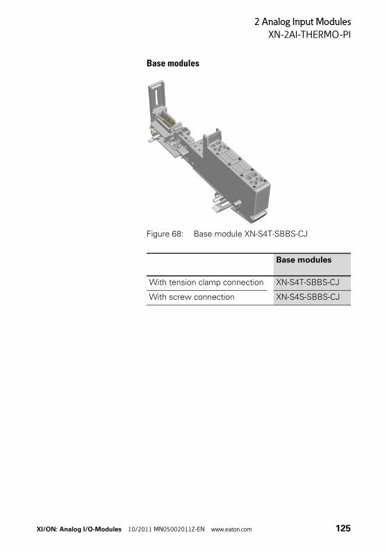
2 Analog Input Modules
XN-2AI-THERMO-PI
Base modules
Figure 68: Base module XN-S4T-SBBS-CJ
Base modules
With tension clamp connection XN-S4T-SBBS-CJ
With screw connection XN-S4S-SBBS-CJ
XI/ON: Analog I/O-Modules 10/2011 MN05002011Z-EN www.eaton.com 125
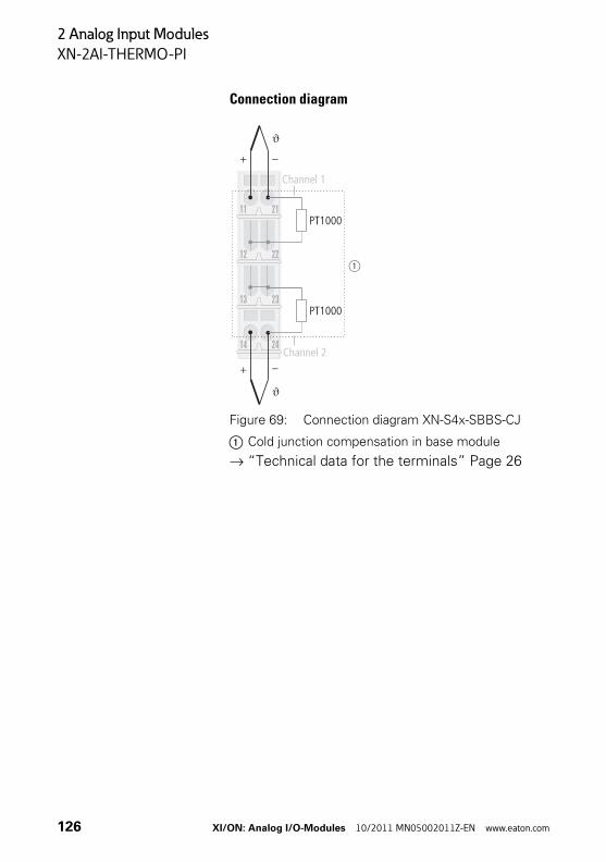
2 Analog Input Modules
XN-2AI-THERMO-PI
Connection diagram
Figure 69: Connection diagram XN-S4x-SBBS-CJ
a Cold junction compensation in base module
→ “Technical data for the terminals” Page 26
Channel 1
Channel 2
126 XI/ON: Analog I/O-Modules 10/2011 MN05002011Z-EN www.eaton.com
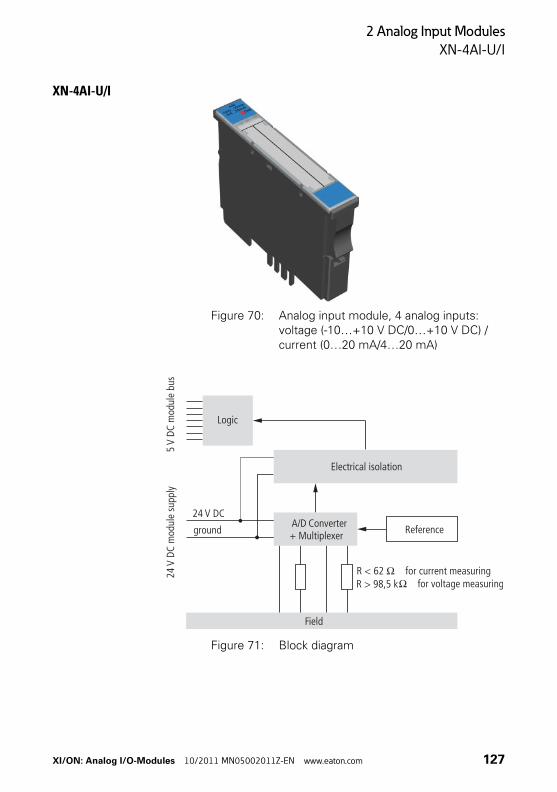
2 Analog Input Modules
XN-4AI-U/I
XN-4AI-U/I
Figure 70: Analog input module, 4 analog inputs: voltage (-10…+10 V DC/0…+10 V DC) / current (0…20 mA/4…20 mA)
Figure 71: Block diagram
Logic
24m
odul
e su
pply
V DC
5m
odul
e bu
sV
DC
Electrical isolation
R < 62 O for current measuring
Field
A/D Converter+ Multiplexer Reference
24 V DC
ground
R > 98,5 kO for voltage measuring
XI/ON: Analog I/O-Modules 10/2011 MN05002011Z-EN www.eaton.com 127
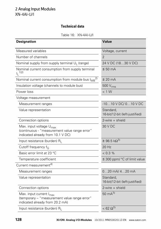
2 Analog Input Modules
XN-4AI-U/I
Technical data
Table 16: XN-4AI-U/I
Designation Value
Measured variables Voltage, current
Number of channels 2
Nominal supply from supply terminal UL (range) 24 V DC (18…30 V DC)
Nominal current consumption from supply terminal IL
1)2)≦ 50 mA
Nominal current consumption from module bus IMB2) ≦ 20 mA
Insulation voltage (channels to module bus) 500 Vrms
Power loss < 1 W
Voltage measurement
Measurement ranges -10…10 V DC/ 0…10 V DC
Value representation Standard, 16-bit/12-bit (left-justified)
Connection options 2-wire + shield
Max. input voltage Umax(continuous - “measurement value range error” indicated already from 10.1 V DC)
30 V DC
Input resistance (burden) RL ≧ 98.5 kΩ3)
Cutoff frequency fG 20 Hz
Basic error limit at 23 °C < 0.3 %
Temperature coefficient ≦ 300 ppm/ °C of limit value
Current measurement4)
Measurement ranges 0…20 mA/ 4…20 mA
Value representation Standard, 16-bit/12-bit (left-justified)
Connection options 2-wire + shield
Max. input current Imax (temporary – “measurement value range error” indicated already from 20.2 mA)
50 mA3)
Input resistance (burden) RL < 62 Ω3)
128 XI/ON: Analog I/O-Modules 10/2011 MN05002011Z-EN www.eaton.com
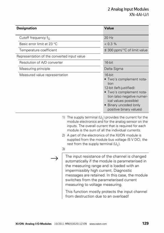
2 Analog Input Modules
XN-4AI-U/I
1) The supply terminal (UL) provides the current for the module electronics and for the analog sensor on the inputs. The overall current that is required for each module is the sum of all the individual currents.
2) A part of the electronics of the XI/ON module is supplied from the module bus voltage (5 V DC), the rest from the supply terminal (UL).
3)
Cutoff frequency fG 20 Hz
Basic error limit at 23 °C < 0.3 %
Temperature coefficient ≦ 300 ppm/ °C of limit value
Representation of the converted input value
Resolution of A/D converter 16-bit
Measuring principle Delta Sigma
Measured value representation 16-bit:• Two's complement nota-
tion12-bit (left-justified):• Two's complement nota-
tion (also negative numer-ical values possible)
• Binary uncoded (only positive binary values)
Designation Value
→ The input resistance of the channel is changed automatically if the module is parameterised in the measuring range and is loaded with an impermissibly high current. Diagnostic messages are retained. In this case, the module switches from the parameterised current measuring to voltage measuring.
This function mostly protects the input channel from destruction due to an overload!
XI/ON: Analog I/O-Modules 10/2011 MN05002011Z-EN www.eaton.com 129
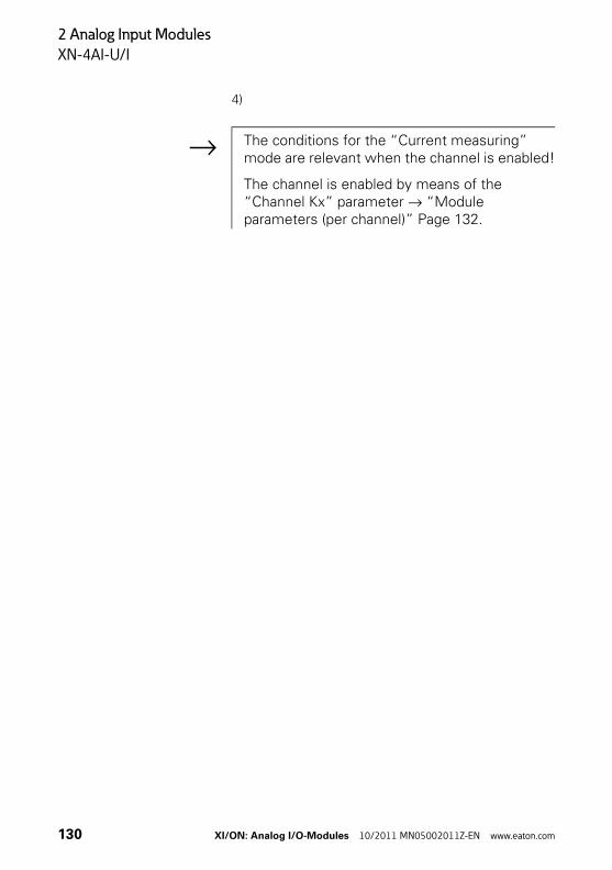
2 Analog Input Modules
XN-4AI-U/I
4)
→ The conditions for the “Current measuring” mode are relevant when the channel is enabled!
The channel is enabled by means of the “Channel Kx” parameter → “Module parameters (per channel)” Page 132.
130 XI/ON: Analog I/O-Modules 10/2011 MN05002011Z-EN www.eaton.com
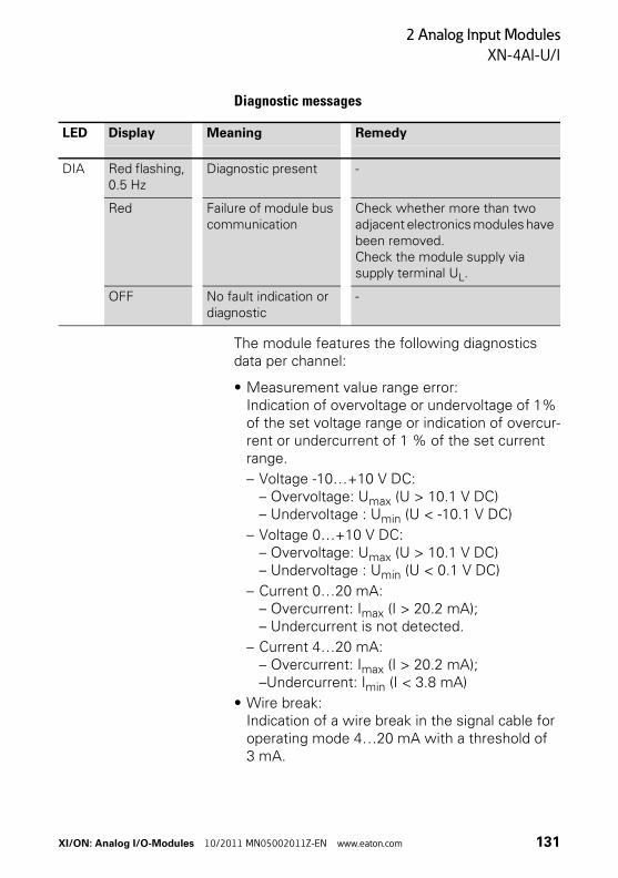
2 Analog Input Modules
XN-4AI-U/I
Diagnostic messages
The module features the following diagnostics data per channel:
• Measurement value range error:Indication of overvoltage or undervoltage of 1% of the set voltage range or indication of overcur-rent or undercurrent of 1 % of the set current range.
– Voltage -10…+10 V DC:– Overvoltage: Umax (U > 10.1 V DC)– Undervoltage : Umin (U < -10.1 V DC)
– Voltage 0…+10 V DC:– Overvoltage: Umax (U > 10.1 V DC)– Undervoltage : Umin (U < 0.1 V DC)
– Current 0…20 mA:– Overcurrent: Imax (I > 20.2 mA);– Undercurrent is not detected.
– Current 4…20 mA:– Overcurrent: Imax (I > 20.2 mA);–Undercurrent: Imin (I < 3.8 mA)
• Wire break:Indication of a wire break in the signal cable for operating mode 4…20 mA with a threshold of 3 mA.
LED Display Meaning Remedy
DIA Red flashing, 0.5 Hz
Diagnostic present -
Red Failure of module bus communication
Check whether more than two adjacent electronics modules have been removed.Check the module supply via supply terminal UL.
OFF No fault indication or diagnostic
-
XI/ON: Analog I/O-Modules 10/2011 MN05002011Z-EN www.eaton.com 131
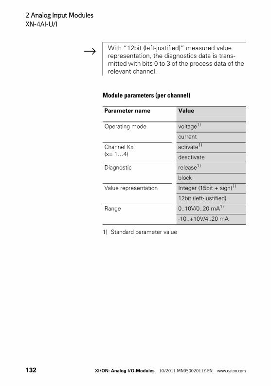
2 Analog Input Modules
XN-4AI-U/I
Module parameters (per channel)
1) Standard parameter value
→ With “12bit (left-justified)” measured value representation, the diagnostics data is trans-mitted with bits 0 to 3 of the process data of the relevant channel.
Parameter name Value
Operating mode voltage1)
current
Channel Kx(x= 1…4)
activate1)
deactivate
Diagnostic release1)
block
Value representation Integer (15bit + sign)1)
12bit (left-justified)
Range 0..10V/0..20 mA1)
-10..+10V/4..20 mA
132 XI/ON: Analog I/O-Modules 10/2011 MN05002011Z-EN www.eaton.com
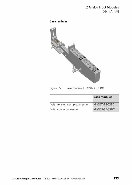
2 Analog Input Modules
XN-4AI-U/I
Base modules
Figure 72: Base module XN-S6T-SBCSBC
Base modules
With tension clamp connection XN-S6T-SBCSBC
With screw connection XN-S6S-SBCSBC
XI/ON: Analog I/O-Modules 10/2011 MN05002011Z-EN www.eaton.com 133
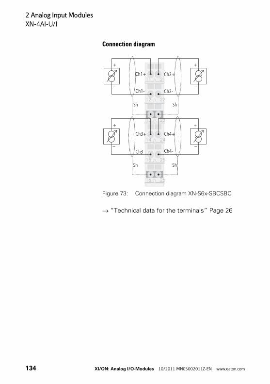
2 Analog Input Modules
XN-4AI-U/I
Connection diagram
Figure 73: Connection diagram XN-S6x-SBCSBC
→ “Technical data for the terminals” Page 26
23
22
21
13
12
11
2414
2616
2515
Sh Sh
+ +
– –
Sh Sh
+ +
– –
Ch1+
Ch3-
Ch3+
Ch1-
Ch2+
Ch4-
Ch4+
Ch2-
134 XI/ON: Analog I/O-Modules 10/2011 MN05002011Z-EN www.eaton.com
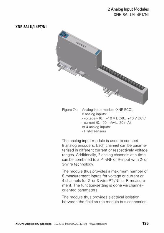
2 Analog Input Modules
XNE-8AI-U/I-4PT/NI
XNE-8AI-U/I-4PT/NI
Figure 74: Analog input module (XNE ECO), 8 analog inputs: - voltage (-10…+10 V DC/0…+10 V DC) / - current (0…20 mA/4…20 mA) or 4 analog inputs: - PT/NI sensors
The analog input module is used to connect 8 analog encoders. Each channel can be parame-terized in different current or respectively voltage ranges. Additionally, 2 analog channels at a time can be combined to a PT-/NI- or R-input with 2- or 3-wire technology.
The module thus provides a maximum number of 8 measurement inputs for voltage or current or 4 channels for 2- or 3-wire PT-/NI- or R-measure-ment. The function-setting is done via channel-oriented parameters.
The module thus provides electrical isolation between the field an the module bus connection.
XI/ON: Analog I/O-Modules 10/2011 MN05002011Z-EN www.eaton.com 135
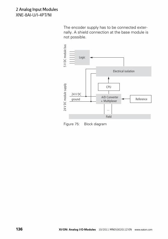
2 Analog Input Modules
XNE-8AI-U/I-4PT/NI
The encoder supply has to be connected exter-nally. A shield connection at the base module is not possible.
Figure 75: Block diagram
Logic
24m
odul
e su
pply
V DC
5m
odul
e bu
sV
DC
Electrical isolation
A/D Converter+ Multiplexer Reference
24 V DC
ground
CPU
Field
...
136 XI/ON: Analog I/O-Modules 10/2011 MN05002011Z-EN www.eaton.com
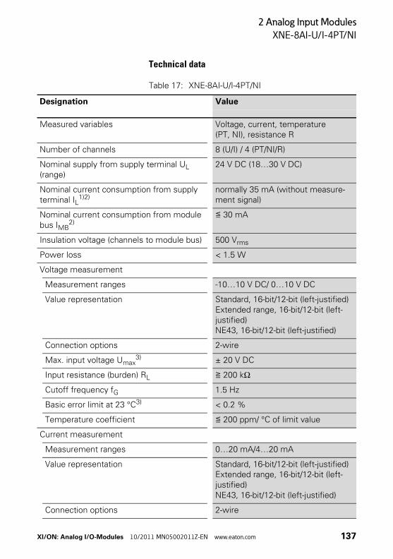
2 Analog Input Modules
XNE-8AI-U/I-4PT/NI
Technical data
Table 17: XNE-8AI-U/I-4PT/NI
Designation Value
Measured variables Voltage, current, temperature (PT, NI), resistance R
Number of channels 8 (U/I) / 4 (PT/NI/R)
Nominal supply from supply terminal UL (range)
24 V DC (18…30 V DC)
Nominal current consumption from supply terminal IL
1)2)normally 35 mA (without measure-ment signal)
Nominal current consumption from module bus IMB
2)≦ 30 mA
Insulation voltage (channels to module bus) 500 Vrms
Power loss < 1.5 W
Voltage measurement
Measurement ranges -10…10 V DC/ 0…10 V DC
Value representation Standard, 16-bit/12-bit (left-justified)Extended range, 16-bit/12-bit (left-justified)NE43, 16-bit/12-bit (left-justified)
Connection options 2-wire
Max. input voltage Umax3) ± 20 V DC
Input resistance (burden) RL ≧ 200 kΩ
Cutoff frequency fG 1.5 Hz
Basic error limit at 23 °C3) < 0.2 %
Temperature coefficient ≦ 200 ppm/ °C of limit value
Current measurement
Measurement ranges 0…20 mA/4…20 mA
Value representation Standard, 16-bit/12-bit (left-justified)Extended range, 16-bit/12-bit (left-justified)NE43, 16-bit/12-bit (left-justified)
Connection options 2-wire
XI/ON: Analog I/O-Modules 10/2011 MN05002011Z-EN www.eaton.com 137
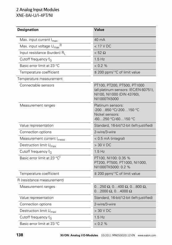
2 Analog Input Modules
XNE-8AI-U/I-4PT/NI
Max. input current Imax 40 mA
Max. input voltage Umax3) < 17 V DC
Input resistance (burden) RL < 52 Ω
Cutoff frequency fG 1.5 Hz
Basic error limit at 23 °C < 0.2 %
Temperature coefficient ≦ 200 ppm/ °C of limit value
Temperature measurement
Connectable sensors PT100, PT200, PT500, PT1000 (all platinum sensors: IEC/EN 60751), NI100, NI1000 (DIN 43760), NI1000TK5000
Measurement ranges Platinum sensors:-200…850 °C/-200…150 °CNickel sensors:-60…250 °C/-60…150 °C
Value representation Standard, 16-bit/12-bit (left-justified)
Connection options 2-wire/3-wire
Measurement current Imess < 0.5 mA (integral)
Destruction limit Umax > 30 V DC
Cutoff frequency fG 1.5 Hz
Basic error limit at 23 °C) PT100, NI100: 0.35 %PT200, PT500, PT1000, NI1000, NI1000TK5000: 0.2 %
Temperature coefficient ≦ 200 ppm/ °C of limit value
R (resistance measurement)
Measurement ranges 0…250 Ω, 0…400 Ω, 0…800 Ω, 0…2000 Ω, 0…4000 Ω
Value representation Standard, 16-bit/12-bit (left-justified)
Connection options 2-wire/3-wire
Destruction limit Umax > 30 V DC
Cutoff frequency fG 1.5 Hz
Basic error limit at 23 °C < 0.2 %
Designation Value
138 XI/ON: Analog I/O-Modules 10/2011 MN05002011Z-EN www.eaton.com
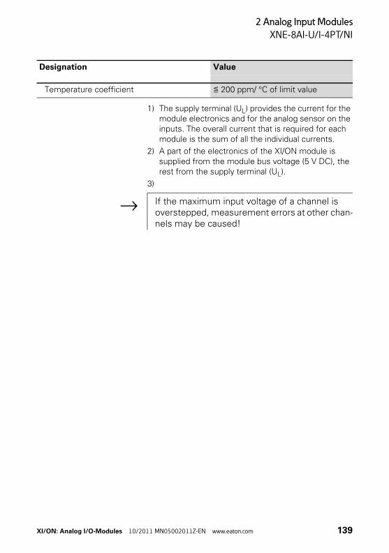
2 Analog Input Modules
XNE-8AI-U/I-4PT/NI
1) The supply terminal (UL) provides the current for the module electronics and for the analog sensor on the inputs. The overall current that is required for each module is the sum of all the individual currents.
2) A part of the electronics of the XI/ON module is supplied from the module bus voltage (5 V DC), the rest from the supply terminal (UL).
3)
Temperature coefficient ≦ 200 ppm/ °C of limit value
Designation Value
→ If the maximum input voltage of a channel is overstepped, measurement errors at other chan-nels may be caused!
XI/ON: Analog I/O-Modules 10/2011 MN05002011Z-EN www.eaton.com 139
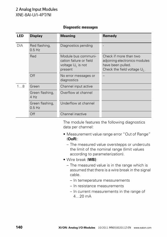
2 Analog Input Modules
XNE-8AI-U/I-4PT/NI
Diagnostic messages
The module features the following diagnostics data per channel:
• Measurement value range error “Out of Range” (OoR):
– The measured value overstepps or undercuts the limit of the nominal range (limit values according to parameterization).
• Wire break (WB):
– The measured value is in the range which is assumed that there is a wire break in the signal cable.
– In temeperature messurements
– In resistance measurements
– In current measurements in the range of 4…20 mA
LED Display Meaning Remedy
DIA Red flashing, 0.5 Hz
Diagnostics pending -
Red Module bus communi-cation failure or field voltage UL is not present
Check if more than two adjoining electronics modules have been pulled.Check the field voltage UL.
Off No error messages or diagnostics
–
1…8 Green Channel input active
Green flashing, 4 Hz
Overflow at channel
Green flashing, 0.5 Hz
Underflow at channel
Off Channel inactive
140 XI/ON: Analog I/O-Modules 10/2011 MN05002011Z-EN www.eaton.com
2 Analog Input Modules
XNE-8AI-U/I-4PT/NI
• Short-circuit (SC):
– The measured value is in the range which is assumed that there is a short-circuit.
– In temeperature messurements:Threshold: 5 Ω (loop resistance)
– 3-wire measurements with PT100 sensors cannot differentiate between a short-circuit and a wire break at temperatures below -177 °C. In this case, the diagnostic "shortcircuit" is generated.
• Overflow / Underflow (OUFL):
– The measured value exceeds the measure-ment range (limit values according to parame-terization). The module cannot measure this value. The return value is the maximum or minimum value which can be measured.
• Hardware error (HW Error):
– Exampels: CRC error, calibration errors…
– The return value of the measured value is “0”.
→ The switching thresholds depend on the setting of the module parameter operation mode Kx. The switching thresholds can be found in the corresponding section from Page 146 on.
→ In the measurement ranges of current measure-ment, the module switches automatically to the voltage measurement after 300 ms if I > 40.0 mA. For the 300 ms, a current of max. 500 mA is accepted. After this, a periodical switching to current measurement is done. If the current falls again to the permissible range, the module switches permanently back to current measurement. During this procedure, the transmitted value is always the measure-ment range end value.Please consider the module’s maximum input voltage!
XI/ON: Analog I/O-Modules 10/2011 MN05002011Z-EN www.eaton.com 141
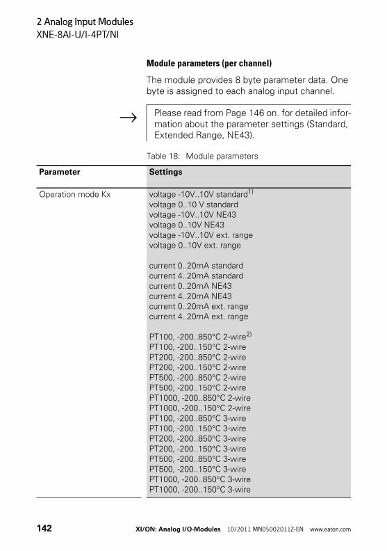
2 Analog Input Modules
XNE-8AI-U/I-4PT/NI
Module parameters (per channel)
The module provides 8 byte parameter data. One byte is assigned to each analog input channel.
Table 18: Module parameters
→ Please read from Page 146 on. for detailed infor-mation about the parameter settings (Standard, Extended Range, NE43).
Parameter Settings
Operation mode Kx voltage -10V..10V standard1) voltage 0..10 V standardvoltage -10V..10V NE43voltage 0..10V NE43voltage -10V..10V ext. rangevoltage 0..10V ext. range
current 0..20mA standardcurrent 4..20mA standardcurrent 0..20mA NE43current 4..20mA NE43current 0..20mA ext. rangecurrent 4..20mA ext. range
PT100, -200..850°C 2-wire2) PT100, -200..150°C 2-wirePT200, -200..850°C 2-wirePT200, -200..150°C 2-wirePT500, -200..850°C 2-wirePT500, -200..150°C 2-wirePT1000, -200..850°C 2-wirePT1000, -200..150°C 2-wirePT100, -200..850°C 3-wirePT100, -200..150°C 3-wirePT200, -200..850°C 3-wirePT200, -200..150°C 3-wirePT500, -200..850°C 3-wirePT500, -200..150°C 3-wirePT1000, -200..850°C 3-wirePT1000, -200..150°C 3-wire
142 XI/ON: Analog I/O-Modules 10/2011 MN05002011Z-EN www.eaton.com
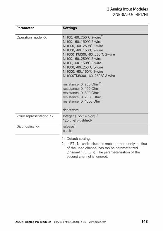
2 Analog Input Modules
XNE-8AI-U/I-4PT/NI
1) Default settings
2) In PT-, NI- and resistance measurement, only the first of the used channel has too be parameterized (channel 1, 3, 5, 7). The parameterization of the second channel is ignored.
Operation mode Kx NI100, -60..250°C 2-wire2) NI100, -60..150°C 2-wireNI1000, -60..250°C 2-wireNI1000, -60..150°C 2-wireNI1000TK5000, -60..250°C 2-wireNI100, -60..250°C 3-wireNI100, -60..150°C 3-wireNI1000, -60..250°C 3-wireNI1000, -60..150°C 3-wireNI1000TK5000, -60..250°C 3-wire
resistance, 0..250 Ohm2) resistance, 0..400 Ohmresistance, 0..800 Ohmresistance, 0..2000 Ohmresistance, 0..4000 Ohm
deactivate
Value representation Kx Integer (15bit + sign)1) 12bit (left-justified)
Diagnostics Kx release1) block
Parameter Settings
XI/ON: Analog I/O-Modules 10/2011 MN05002011Z-EN www.eaton.com 143
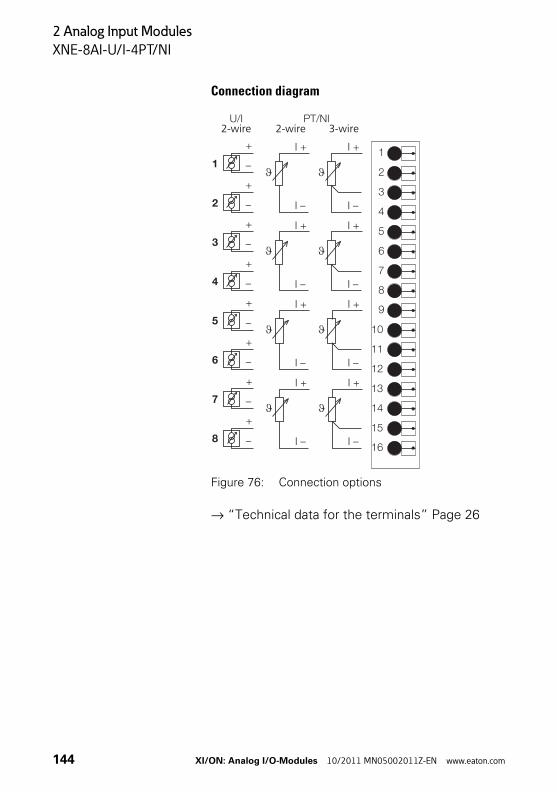
2 Analog Input Modules
XNE-8AI-U/I-4PT/NI
Connection diagram
Figure 76: Connection options
→ “Technical data for the terminals” Page 26
2-wire 2-wire 3-wire
144 XI/ON: Analog I/O-Modules 10/2011 MN05002011Z-EN www.eaton.com
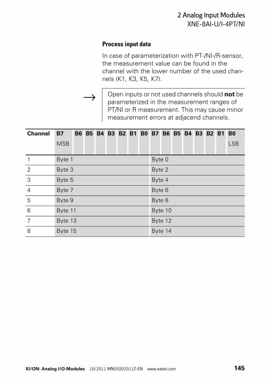
2 Analog Input Modules
XNE-8AI-U/I-4PT/NI
Process input data
In case of parameterization with PT-/NI-/R-sensor, the measurement value can be found in the channel with the lower number of the used chan-nels (K1, K3, K5, K7).
→ Open inputs or not used channels should not be parameterized in the measurement ranges of PT/NI or R measurement. This may cause minor measurement errors at adjacend channels.
Channel B7 B6 B5 B4 B3 B2 B1 B0 B7 B6 B5 B4 B3 B2 B1 B0
MSB LSB
1 Byte 1 Byte 0
2 Byte 3 Byte 2
3 Byte 5 Byte 4
4 Byte 7 Byte 6
5 Byte 9 Byte 8
6 Byte 11 Byte 10
7 Byte 13 Byte 12
8 Byte 15 Byte 14
XI/ON: Analog I/O-Modules 10/2011 MN05002011Z-EN www.eaton.com 145
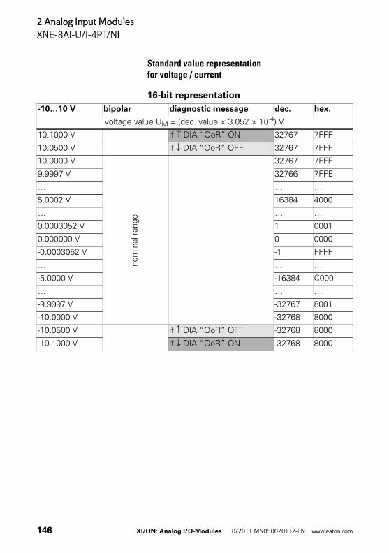
2 Analog Input Modules
XNE-8AI-U/I-4PT/NI
Standard value representationfor voltage / current
16-bit representation
-10…10 V bipolar diagnostic message dec. hex.
voltage value UM = (dec. value × 3.052 × 10⁻⁴) V
10.1000 V if ↑ DIA “OoR” ON 32767 7FFF
10.0500 V if ↓ DIA “OoR” OFF 32767 7FFF
10.0000 V
no
min
al r
ange
32767 7FFF
9.9997 V 32766 7FFE
… … …
5.0002 V 16384 4000
… … …
0.0003052 V 1 0001
0.000000 V 0 0000
-0.0003052 V -1 FFFF
… … …
-5.0000 V -16384 C000
… … …
-9.9997 V -32767 8001
-10.0000 V -32768 8000
-10.0500 V if ↑ DIA “OoR” OFF -32768 8000
-10.1000 V if ↓ DIA “OoR” ON -32768 8000
146 XI/ON: Analog I/O-Modules 10/2011 MN05002011Z-EN www.eaton.com
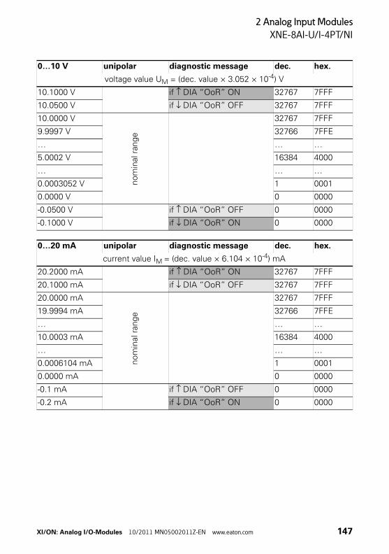
2 Analog Input Modules
XNE-8AI-U/I-4PT/NI
0…10 V unipolar diagnostic message dec. hex.
voltage value UM = (dec. value × 3.052 × 10⁻⁴) V
10.1000 V if ↑ DIA “OoR” ON 32767 7FFF
10.0500 V if ↓ DIA “OoR” OFF 32767 7FFF
10.0000 V
nom
inal
ran
ge
32767 7FFF
9.9997 V 32766 7FFE
… … …
5.0002 V 16384 4000
… … …
0.0003052 V 1 0001
0.0000 V 0 0000
-0.0500 V if ↑ DIA “OoR” OFF 0 0000
-0.1000 V if ↓ DIA “OoR” ON 0 0000
0…20 mA unipolar diagnostic message dec. hex.
current value IM = (dec. value × 6.104 × 10⁻⁴) mA
20.2000 mA if ↑ DIA “OoR” ON 32767 7FFF
20.1000 mA if ↓ DIA “OoR” OFF 32767 7FFF
20.0000 mA
nom
inal r
ange
32767 7FFF
19.9994 mA 32766 7FFE
… … …
10.0003 mA 16384 4000
… … …
0.0006104 mA 1 0001
0.0000 mA 0 0000
-0.1 mA if ↑ DIA “OoR” OFF 0 0000
-0.2 mA if ↓ DIA “OoR” ON 0 0000
XI/ON: Analog I/O-Modules 10/2011 MN05002011Z-EN www.eaton.com 147
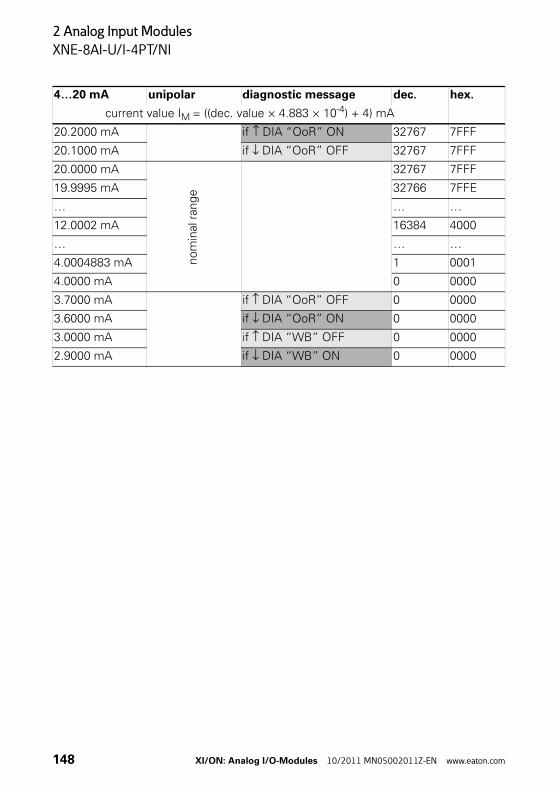
2 Analog Input Modules
XNE-8AI-U/I-4PT/NI
4…20 mA unipolar diagnostic message dec. hex.
current value IM = ((dec. value × 4.883 × 10⁻⁴) + 4) mA
20.2000 mA if ↑ DIA “OoR” ON 32767 7FFF
20.1000 mA if ↓ DIA “OoR” OFF 32767 7FFF
20.0000 mA
nom
inal
ran
ge
32767 7FFF
19.9995 mA 32766 7FFE
… … …
12.0002 mA 16384 4000
… … …
4.0004883 mA 1 0001
4.0000 mA 0 0000
3.7000 mA if ↑ DIA “OoR” OFF 0 0000
3.6000 mA if ↓ DIA “OoR” ON 0 0000
3.0000 mA if ↑ DIA “WB” OFF 0 0000
2.9000 mA if ↓ DIA “WB” ON 0 0000
148 XI/ON: Analog I/O-Modules 10/2011 MN05002011Z-EN www.eaton.com
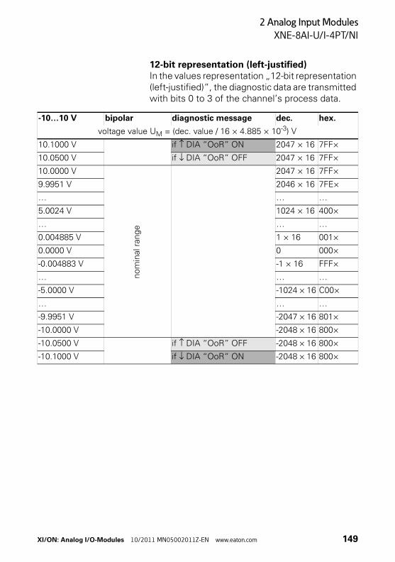
2 Analog Input Modules
XNE-8AI-U/I-4PT/NI
12-bit representation (left-justified)In the values representation „12-bit representation (left-justified)“, the diagnostic data are transmitted with bits 0 to 3 of the channel’s process data.
-10…10 V bipolar diagnostic message dec. hex.
voltage value UM = (dec. value / 16 × 4.885 × 10-3) V
10.1000 V if ↑ DIA “OoR” ON 2047 × 16 7FF×
10.0500 V if ↓ DIA “OoR” OFF 2047 × 16 7FF×
10.0000 V
nom
inal
ran
ge
2047 × 16 7FF×
9.9951 V 2046 × 16 7FE×
… … …
5.0024 V 1024 × 16 400×
… … …
0.004885 V 1 × 16 001×
0.0000 V 0 000×
-0.004883 V -1 × 16 FFF×
… … …
-5.0000 V -1024 × 16 C00×
… … …
-9.9951 V -2047 × 16 801×
-10.0000 V -2048 × 16 800×
-10.0500 V if ↑ DIA “OoR” OFF -2048 × 16 800×
-10.1000 V if ↓ DIA “OoR” ON -2048 × 16 800×
XI/ON: Analog I/O-Modules 10/2011 MN05002011Z-EN www.eaton.com 149
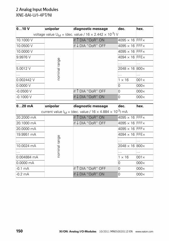
2 Analog Input Modules
XNE-8AI-U/I-4PT/NI
0…10 V unipolar diagnostic message dec. hex.
voltage value UM = (dec. value / 16 × 2.442 × 10-3) V
10.1000 V if ↑ DIA “OoR” ON 4095 × 16 FFF×
10.0500 V if ↓ DIA “OoR” OFF 4095 × 16 FFF×
10.0000 V
nom
inal
ran
ge
4095 × 16 FFF×
9.9976 V 4094 × 16 FFE×
… … …
5.0012 V 2048 × 16 800×
… … …
0.002442 V 1 × 16 001×
0.0000 V 0 000×
-0.0500 V if ↑ DIA “OoR” OFF 0 000×
-0.1000 V if ↓ DIA “OoR” ON 0 000×
0…20 mA unipolar diagnostic message dec. hex.
current value IM = (dec. value / 16 × 4.884 × 10-3) mA
20.2000 mA if ↑ DIA “OoR” ON 4095 × 16 FFF×
20.1000 mA if ↓ DIA “OoR” OFF 4095 × 16 FFF×
20.0000 mA
nom
inal
ran
ge
4095 × 16 FFF×
19.9951 mA 4094 × 16 FFE×
… … …
10.0024 mA 2048 × 16 800×
… … …
0.004884 mA 1 × 16 001×
0.0000 mA 0 000×
-0.1 mA if ↑ DIA “OoR” OFF 0 000×
-0.2 mA if ↓ DIA “OoR” ON 0 000×
150 XI/ON: Analog I/O-Modules 10/2011 MN05002011Z-EN www.eaton.com
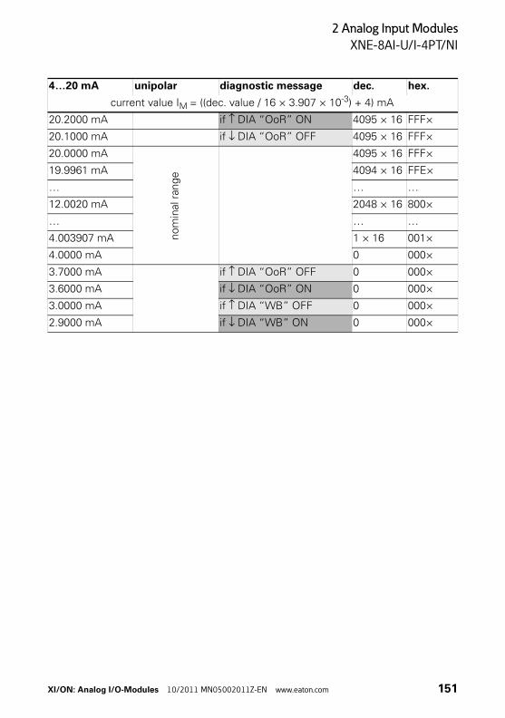
2 Analog Input Modules
XNE-8AI-U/I-4PT/NI
4…20 mA unipolar diagnostic message dec. hex.
current value IM = ((dec. value / 16 × 3.907 × 10-3) + 4) mA
20.2000 mA if ↑ DIA “OoR” ON 4095 × 16 FFF×
20.1000 mA if ↓ DIA “OoR” OFF 4095 × 16 FFF×
20.0000 mA
nom
inal
ran
ge
4095 × 16 FFF×
19.9961 mA 4094 × 16 FFE×
… … …
12.0020 mA 2048 × 16 800×
… … …
4.003907 mA 1 × 16 001×
4.0000 mA 0 000×
3.7000 mA if ↑ DIA “OoR” OFF 0 000×
3.6000 mA if ↓ DIA “OoR” ON 0 000×
3.0000 mA if ↑ DIA “WB” OFF 0 000×
2.9000 mA if ↓ DIA “WB” ON 0 000×
XI/ON: Analog I/O-Modules 10/2011 MN05002011Z-EN www.eaton.com 151
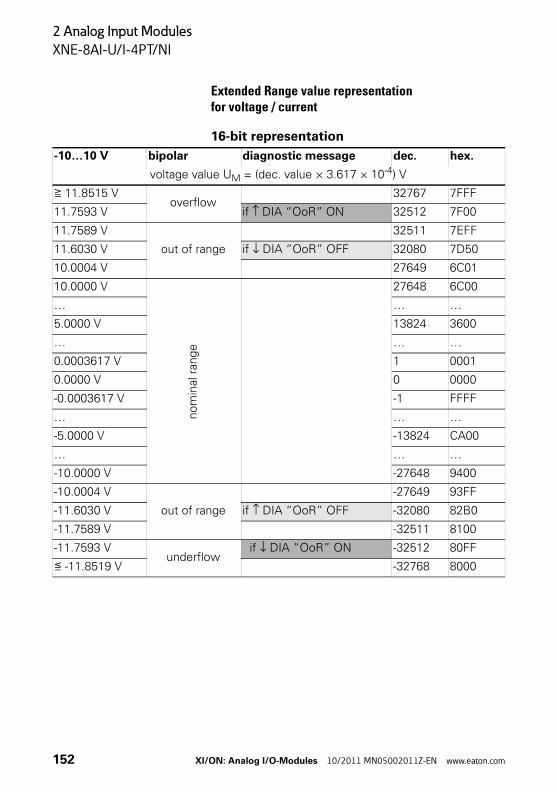
2 Analog Input Modules
XNE-8AI-U/I-4PT/NI
Extended Range value representationfor voltage / current
16-bit representation
-10…10 V bipolar diagnostic message dec. hex.
voltage value UM = (dec. value × 3.617 × 10⁻⁴) V
≧ 11.8515 Voverflow
32767 7FFF
11.7593 V if ↑ DIA “OoR” ON 32512 7F00
11.7589 V
out of range
32511 7EFF
11.6030 V if ↓ DIA “OoR” OFF 32080 7D50
10.0004 V 27649 6C01
10.0000 V
no
min
al r
ang
e
27648 6C00
… … …
5.0000 V 13824 3600
… … …
0.0003617 V 1 0001
0.0000 V 0 0000
-0.0003617 V -1 FFFF
… … …
-5.0000 V -13824 CA00
… … …
-10.0000 V -27648 9400
-10.0004 V
out of range
-27649 93FF
-11.6030 V if ↑ DIA “OoR” OFF -32080 82B0
-11.7589 V -32511 8100
-11.7593 Vunderflow
if ↓ DIA “OoR” ON -32512 80FF
≦ -11.8519 V -32768 8000
152 XI/ON: Analog I/O-Modules 10/2011 MN05002011Z-EN www.eaton.com
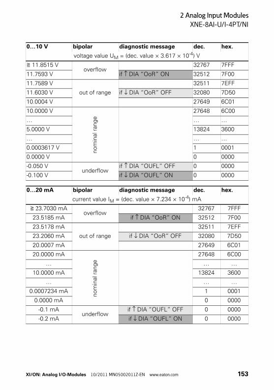
2 Analog Input Modules
XNE-8AI-U/I-4PT/NI
0…10 V bipolar diagnostic message dec. hex.
voltage value UM = (dec. value × 3.617 × 10⁻⁴) V
≧ 11.8515 Voverflow
32767 7FFF
11.7593 V if ↑ DIA “OoR” ON 32512 7F00
11.7589 V
out of range
32511 7EFF
11.6030 V if ↓ DIA “OoR” OFF 32080 7D50
10.0004 V 27649 6C01
10.0000 V
nom
inal
ran
ge
27648 6C00
… … …
5.0000 V 13824 3600
… … …
0.0003617 V 1 0001
0.0000 V 0 0000
-0.050 Vunderflow
if ↑ DIA “OUFL” OFF 0 0000
-0.100 V if ↓ DIA “OUFL” ON 0 0000
0…20 mA bipolar diagnostic message dec. hex.
current value IM = (dec. value × 7.234 × 10⁻⁴) mA
≧ 23.7030 mAoverflow
32767 7FFF
23.5185 mA if ↑ DIA “OoR” ON 32512 7F00
23.5178 mA
out of range
32511 7EFF
23.2060 mA if ↓ DIA “OoR” OFF 32080 7D50
20.0007 mA 27649 6C01
20.0000 mA
no
min
al r
ang
e
27648 6C00
… … …
10.0000 mA 13824 3600
… … …
0.0007234 mA 1 0001
0.0000 mA 0 0000
-0.1 mAunderflow
if ↑ DIA “OUFL” OFF 0 0000
-0.2 mA if ↓ DIA “OUFL” ON 0 0000
XI/ON: Analog I/O-Modules 10/2011 MN05002011Z-EN www.eaton.com 153
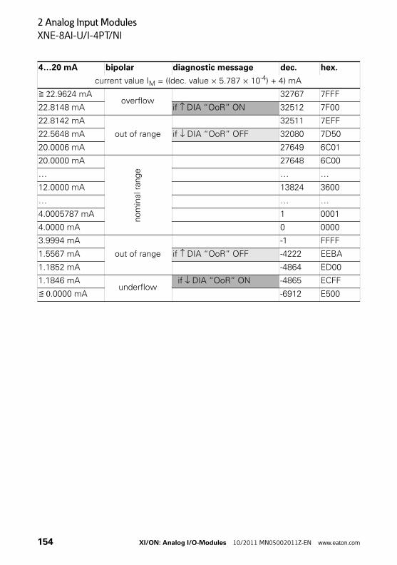
2 Analog Input Modules
XNE-8AI-U/I-4PT/NI
4…20 mA bipolar diagnostic message dec. hex.
current value IM = ((dec. value × 5.787 × 10⁻⁴) + 4) mA
≧ 22.9624 mAoverflow
32767 7FFF
22.8148 mA if ↑ DIA “OoR” ON 32512 7F00
22.8142 mA
out of range
32511 7EFF
22.5648 mA if ↓ DIA “OoR” OFF 32080 7D50
20.0006 mA 27649 6C01
20.0000 mA
nom
inal
ran
ge
27648 6C00
… … …
12.0000 mA 13824 3600
… … …
4.0005787 mA 1 0001
4.0000 mA 0 0000
3.9994 mA
out of range
-1 FFFF
1.5567 mA if ↑ DIA “OoR” OFF -4222 EEBA
1.1852 mA -4864 ED00
1.1846 mAunderflow
if ↓ DIA “OoR” ON -4865 ECFF
≦ 0.0000 mA -6912 E500
154 XI/ON: Analog I/O-Modules 10/2011 MN05002011Z-EN www.eaton.com
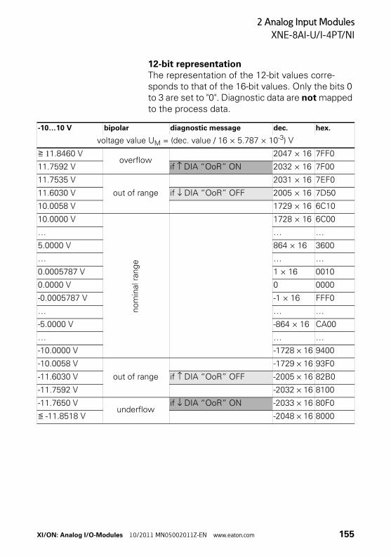
2 Analog Input Modules
XNE-8AI-U/I-4PT/NI
12-bit representationThe representation of the 12-bit values corre-sponds to that of the 16-bit values. Only the bits 0 to 3 are set to "0". Diagnostic data are not mapped to the process data.
-10…10 V bipolar diagnostic message dec. hex.
voltage value UM = (dec. value / 16 × 5.787 × 10-3) V
≧ 11.8460 Voverflow
2047 × 16 7FF0
11.7592 V if ↑ DIA “OoR” ON 2032 × 16 7F00
11.7535 V
out of range
2031 × 16 7EF0
11.6030 V if ↓ DIA “OoR” OFF 2005 × 16 7D50
10.0058 V 1729 × 16 6C10
10.0000 V
nom
inal
ran
ge
1728 × 16 6C00
… … …
5.0000 V 864 × 16 3600
… … …
0.0005787 V 1 × 16 0010
0.0000 V 0 0000
-0.0005787 V -1 × 16 FFF0
… … …
-5.0000 V -864 × 16 CA00
… … …
-10.0000 V -1728 × 16 9400
-10.0058 V
out of range
-1729 × 16 93F0
-11.6030 V if ↑ DIA “OoR” OFF -2005 × 16 82B0
-11.7592 V -2032 × 16 8100
-11.7650 Vunderflow
if ↓ DIA “OoR” ON -2033 × 16 80F0
≦ -11.8518 V -2048 × 16 8000
XI/ON: Analog I/O-Modules 10/2011 MN05002011Z-EN www.eaton.com 155
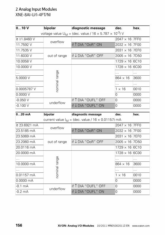
2 Analog Input Modules
XNE-8AI-U/I-4PT/NI
0…10 V bipolar diagnostic message dec. hex.
voltage value UM = (dec. value / 16 × 5.787 × 10-3) V
≧ 11.8460 Voverflow
2047 × 16 7FF0
11.7592 V if ↑ DIA “OoR” ON 2032 × 16 7F00
11.7535 V
out of range
2031 × 16 7EF0
11.6030 V if ↓ DIA “OoR” OFF 2005 × 16 7D50
10.0058 V 1729 × 16 6C10
10.0000 V
nom
inal
ran
ge
1728 × 16 6C00
… … …
5.0000 V 864 × 16 3600
… … …
0.0005787 V 1 × 16 0010
0.0000 V 0 0000
-0.050 Vunderflow
if ↑ DIA “OUFL” OFF 0 0000
-0.100 V if ↓ DIA “OUFL” ON 0 0000
0…20 mA bipolar diagnostic message dec. hex.
current value IM = (dec. value / 16 × 0.01157) mA
≧ 23.6921 mAoverflow
2047 × 16 7FF0
23.5185 mA if ↑ DIA “OoR” ON 2032 × 16 7F00
23.5069 mA
out of range
2031 × 16 7EF0
23.2060 mA if ↓ DIA “OoR” OFF 2005 × 16 7D50
20.0116 mA 1729 × 16 6C10
20.0000 mA
nom
inal
ran
ge
1728 × 16 6C00
… … …
10.0000 mA 864 × 16 3600
… … …
0.01157 mA 1 × 16 0010
0.0000 mA 0 0000
-0.1 mAunderflow
if ↑ DIA “OUFL” OFF 0 0000
-0.2 mA if ↓ DIA “OUFL” ON 0 0000
156 XI/ON: Analog I/O-Modules 10/2011 MN05002011Z-EN www.eaton.com
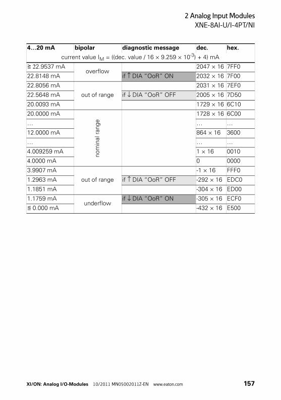
2 Analog Input Modules
XNE-8AI-U/I-4PT/NI
4…20 mA bipolar diagnostic message dec. hex.
current value IM = ((dec. value / 16 × 9.259 × 10-3) + 4) mA
≧ 22.9537 mAoverflow
2047 × 16 7FF0
22.8148 mA if ↑ DIA “OoR” ON 2032 × 16 7F00
22.8056 mA
out of range
2031 × 16 7EF0
22.5648 mA if ↓ DIA “OoR” OFF 2005 × 16 7D50
20.0093 mA 1729 × 16 6C10
20.0000 mA
nom
inal
ran
ge
1728 × 16 6C00
… … …
12.0000 mA 864 × 16 3600
… … …
4.009259 mA 1 × 16 0010
4.0000 mA 0 0000
3.9907 mA
out of range
-1 × 16 FFF0
1.2963 mA if ↑ DIA “OoR” OFF -292 × 16 EDC0
1.1851 mA -304 × 16 ED00
1.1759 mAunderflow
if ↓ DIA “OoR” ON -305 × 16 ECF0
≦ 0.000 mA -432 × 16 E500
XI/ON: Analog I/O-Modules 10/2011 MN05002011Z-EN www.eaton.com 157
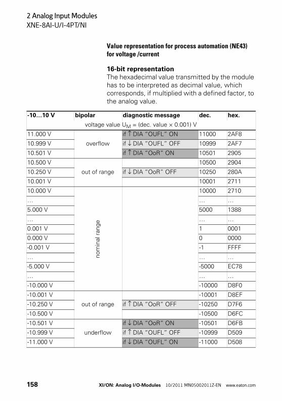
2 Analog Input Modules
XNE-8AI-U/I-4PT/NI
Value representation for process automation (NE43) for voltage /current
16-bit representationThe hexadecimal value transmitted by the module has to be interpreted as decimal value, which corresponds, if multiplied with a defined factor, to the analog value.
-10…10 V bipolar diagnostic message dec. hex.
voltage value UM = (dec. value × 0.001) V
11.000 V
overflow
if ↑ DIA “OUFL” ON 11000 2AF8
10.999 V if ↓ DIA “OUFL” OFF 10999 2AF7
10.501 V if ↑ DIA “OoR” ON 10501 2905
10.500 V
out of range
10500 2904
10.250 V if ↓ DIA “OoR” OFF 10250 280A
10.001 V 10001 2711
10.000 V
nom
inal
rang
e
10000 2710
… … …
5.000 V 5000 1388
… … …
0.001 V 1 0001
0.000 V 0 0000
-0.001 V -1 FFFF
… … …
-5.000 V -5000 EC78
… … …
-10.000 V -10000 D8F0
-10.001 V
out of range
-10001 D8EF
-10.250 V if ↑ DIA “OoR” OFF -10250 D7F6
-10.500 V -10500 D6FC
-10.501 V
underflow
if ↓ DIA “OoR” ON -10501 D6FB
-10.999 V if ↑ DIA “OUFL” OFF -10999 D509
-11.000 V if ↓ DIA “OUFL” ON -11000 D508
158 XI/ON: Analog I/O-Modules 10/2011 MN05002011Z-EN www.eaton.com
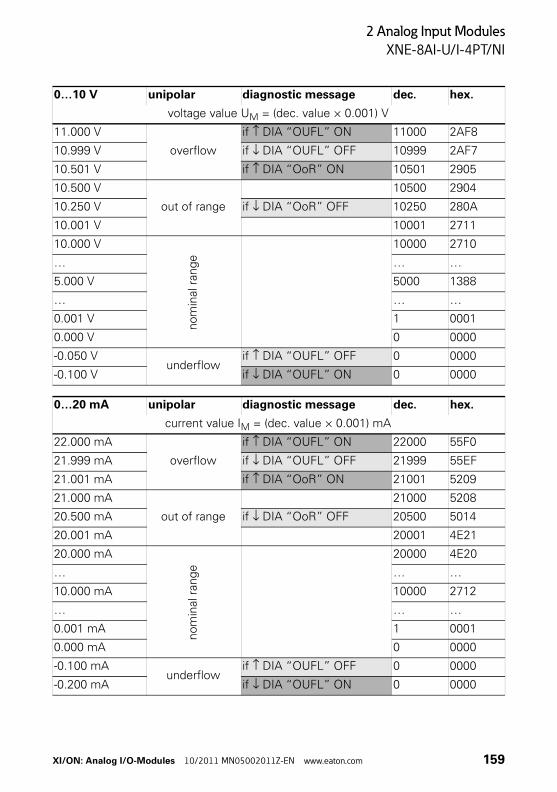
2 Analog Input Modules
XNE-8AI-U/I-4PT/NI
0…10 V unipolar diagnostic message dec. hex.
voltage value UM = (dec. value × 0.001) V
11.000 V
overflow
if ↑ DIA “OUFL” ON 11000 2AF8
10.999 V if ↓ DIA “OUFL” OFF 10999 2AF7
10.501 V if ↑ DIA “OoR” ON 10501 2905
10.500 V
out of range
10500 2904
10.250 V if ↓ DIA “OoR” OFF 10250 280A
10.001 V 10001 2711
10.000 V
nom
inal
ran
ge
10000 2710
… … …
5.000 V 5000 1388
… … …
0.001 V 1 0001
0.000 V 0 0000
-0.050 Vunderflow
if ↑ DIA “OUFL” OFF 0 0000
-0.100 V if ↓ DIA “OUFL” ON 0 0000
0…20 mA unipolar diagnostic message dec. hex.
current value IM = (dec. value × 0.001) mA
22.000 mA
overflow
if ↑ DIA “OUFL” ON 22000 55F0
21.999 mA if ↓ DIA “OUFL” OFF 21999 55EF
21.001 mA if ↑ DIA “OoR” ON 21001 5209
21.000 mA
out of range
21000 5208
20.500 mA if ↓ DIA “OoR” OFF 20500 5014
20.001 mA 20001 4E21
20.000 mA
nom
inal
rang
e
20000 4E20
… … …
10.000 mA 10000 2712
… … …
0.001 mA 1 0001
0.000 mA 0 0000
-0.100 mAunderflow
if ↑ DIA “OUFL” OFF 0 0000
-0.200 mA if ↓ DIA “OUFL” ON 0 0000
XI/ON: Analog I/O-Modules 10/2011 MN05002011Z-EN www.eaton.com 159
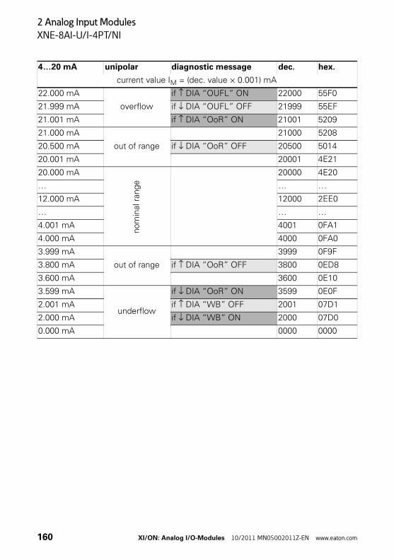
2 Analog Input Modules
XNE-8AI-U/I-4PT/NI
4…20 mA unipolar diagnostic message dec. hex.
current value IM = (dec. value × 0.001) mA
22.000 mA
overflow
if ↑ DIA “OUFL” ON 22000 55F0
21.999 mA if ↓ DIA “OUFL” OFF 21999 55EF
21.001 mA if ↑ DIA “OoR” ON 21001 5209
21.000 mA
out of range
21000 5208
20.500 mA if ↓ DIA “OoR” OFF 20500 5014
20.001 mA 20001 4E21
20.000 mA
nom
inal
ran
ge
20000 4E20
… … …
12.000 mA 12000 2EE0
… … …
4.001 mA 4001 0FA1
4.000 mA 4000 0FA0
3.999 mA
out of range
3999 0F9F
3.800 mA if ↑ DIA “OoR” OFF 3800 0ED8
3.600 mA 3600 0E10
3.599 mA
underflow
if ↓ DIA “OoR” ON 3599 0E0F
2.001 mA if ↑ DIA “WB” OFF 2001 07D1
2.000 mA if ↓ DIA “WB” ON 2000 07D0
0.000 mA 0000 0000
160 XI/ON: Analog I/O-Modules 10/2011 MN05002011Z-EN www.eaton.com
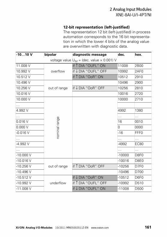
2 Analog Input Modules
XNE-8AI-U/I-4PT/NI
12-bit representation (left-justified)The representation 12 bit (left-justified) in process automation corresponds to the 16 bit representa-tion in which the lower 4 bits of the analog value are overwritten with diagnostic data.
-10…10 V bipolar diagnostic message dec. hex.
voltage value UM = (dec. value × 0.001) V
11.008 V
overflow
if ↑ DIA “OUFL” ON 11008 2B00
10.992 V if ↓ DIA “OUFL” OFF 10992 2AF0
10.512 V if ↑ DIA “OoR” ON 10512 2910
10.496 V
out of range
10496 2900
10.256 V if ↓ DIA “OoR” OFF 10256 2810
10.016 V 10016 2720
10.000 V
no
min
al r
ange
10000 2710
…
4.992 V 4992 1380
… … …
0.016 V 16 0010
0.000 V 0 0000
-0.016 V -16 FFF0
… … …
-4.992 V -4992 EC80
… … …
-10.000 V -10000 D8F0
-10.016 V
out of range
-10016 D8E0
-10.256 V if ↑ DIA “OoR” OFF -10256 D7F0
-10.496 V -10496 D700
-10.512 V
underflow
if ↓ DIA “OoR” ON -10512 D6F0
-10.992 V if ↑ DIA “OUFL” OFF -10992 D510
-11.008 V if ↓ DIA “OUFL” ON -11008 D500
XI/ON: Analog I/O-Modules 10/2011 MN05002011Z-EN www.eaton.com 161
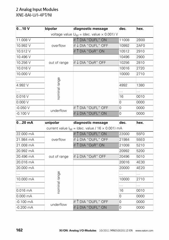
2 Analog Input Modules
XNE-8AI-U/I-4PT/NI
0…10 V bipolar diagnostic message dec. hex.
voltage value UM = (dec. value × 0.001) V
11.008 V
overflow
if ↑ DIA “OUFL” ON 11008 2B00
10.992 V if ↓ DIA “OUFL” OFF 10992 2AF0
10.512 V if ↑ DIA “OoR” ON 10512 2910
10.496 V
out of range
10496 2900
10.256 V if ↓ DIA “OoR” OFF 10256 2810
10.016 V 10016 2720
10.000 V
nom
inal
ran
ge
10000 2710
…
4.992 V 4992 1380
… … …
0.016 V 16 0010
0.000 V 0 0000
-0.050 Vunderflow
if ↑ DIA “OUFL” OFF 0 0000
-0.100 V if ↓ DIA “OUFL” ON 0 0000
0…20 mA unipolar diagnostic message dec. hex.
current value IM = (dec. value / 16 × 0.001) mA
22.000 mA
overflow
if ↑ DIA “OUFL” ON 22000 55F0
21.984 mA if ↓ DIA “OUFL” OFF 21984 55E0
21.008 mA if ↑ DIA “OoR” ON 21008 5210
20.992 mA
out of range
20992 5200
20.496 mA if ↓ DIA “OoR” OFF 20496 5010
20.016 mA 20016 4E30
20.000 mA
nom
inal
rang
e
20000 4E20
… … …
10.000 mA 10000 2710
… … …
0.016 mA 16 0010
0.000 mA 0 0000
-0.100 mAunderflow
if ↑ DIA “OUFL” OFF 0 0000
-0.200 mA if ↓ DIA “OUFL” ON 0 0000
162 XI/ON: Analog I/O-Modules 10/2011 MN05002011Z-EN www.eaton.com
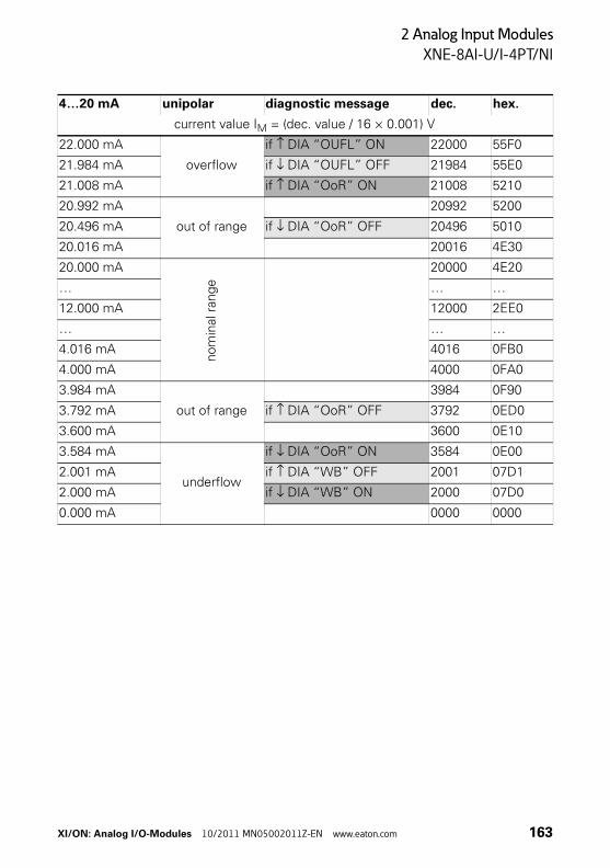
2 Analog Input Modules
XNE-8AI-U/I-4PT/NI
4…20 mA unipolar diagnostic message dec. hex.
current value IM = (dec. value / 16 × 0.001) V
22.000 mA
overflow
if ↑ DIA “OUFL” ON 22000 55F0
21.984 mA if ↓ DIA “OUFL” OFF 21984 55E0
21.008 mA if ↑ DIA “OoR” ON 21008 5210
20.992 mA
out of range
20992 5200
20.496 mA if ↓ DIA “OoR” OFF 20496 5010
20.016 mA 20016 4E30
20.000 mA
nom
inal
ran
ge
20000 4E20
… … …
12.000 mA 12000 2EE0
… … …
4.016 mA 4016 0FB0
4.000 mA 4000 0FA0
3.984 mA
out of range
3984 0F90
3.792 mA if ↑ DIA “OoR” OFF 3792 0ED0
3.600 mA 3600 0E10
3.584 mA
underflow
if ↓ DIA “OoR” ON 3584 0E00
2.001 mA if ↑ DIA “WB” OFF 2001 07D1
2.000 mA if ↓ DIA “WB” ON 2000 07D0
0.000 mA 0000 0000
XI/ON: Analog I/O-Modules 10/2011 MN05002011Z-EN www.eaton.com 163
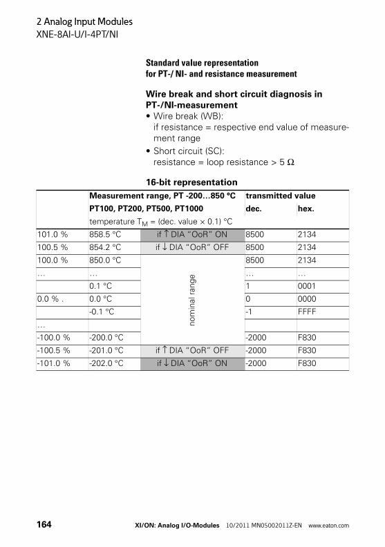
2 Analog Input Modules
XNE-8AI-U/I-4PT/NI
Standard value representationfor PT-/ NI- and resistance measurement
Wire break and short circuit diagnosis in PT-/NI-measurement• Wire break (WB):
if resistance = respective end value of measure-ment range
• Short circuit (SC):resistance = loop resistance > 5 Ω
16-bit representation
Measurement range, PT -200…850 °C transmitted value
PT100, PT200, PT500, PT1000 dec. hex.
temperature TM = (dec. value × 0.1) °C
101.0 % 858.5 °C if ↑ DIA “OoR” ON 8500 2134
100.5 % 854.2 °C if ↓ DIA “OoR” OFF 8500 2134
100.0 % 850.0 °C
nom
inal
ran
ge
8500 2134
… … … …
0.1 °C 1 0001
0.0 % . 0.0 °C 0 0000
-0.1 °C -1 FFFF
…
-100.0 % -200.0 °C -2000 F830
-100.5 % -201.0 °C if ↑ DIA “OoR” OFF -2000 F830
-101.0 % -202.0 °C if ↓ DIA “OoR” ON -2000 F830
164 XI/ON: Analog I/O-Modules 10/2011 MN05002011Z-EN www.eaton.com
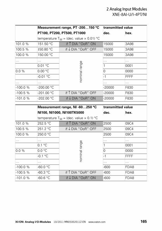
2 Analog Input Modules
XNE-8AI-U/I-4PT/NI
Measurement range, PT -200…150 °C transmitted value
PT100, PT200, PT500, PT1000 dec. hex.
temperature TM = (dec. value × 0.01) °C
101.0 % 151.50 °C if ↑ DIA “OoR” ON 15000 3A98
100.5 % 150.80 °C if ↓ DIA “OoR” OFF 15000 3A98
100.0 % 150.00 °C
nom
inal
ran
ge
15000 3A98
… … … …
0.01 °C 1 0001
0.0 % 0.00 °C 0 0000
-0.01 °C -1 FFFF
… … … …
-100.0 % -200.00 °C -20000 F830
-100.5 % -201.00 °C if ↑ DIA “OoR” OFF -20000 F830
-101.0 % -202.00 °C if ↓ DIA “OoR” ON -20000 F830
Measurement range, NI -60…250 °C transmitted value
NI100, NI1000, NI100TK5000 dec. hex.
temperature TM = (dec. value × 0.1) °C
101.0 % 252.5 °C if ↑ DIA “OoR” ON 2500 09C4
100.5 % 251.2 °C if ↓ DIA “OoR” OFF 2500 09C4
100.0 % 250.0 °C
nom
inal
ran
ge
2500 09C4
… … … …
0.1 °C 1 0001
0.0 % 0.0 °C 0 0000
-0.1 °C -1 FFFF
… … … …
-100.0 % -60.0 °C -600 FDA8
-100.5 % -60.3 °C if ↑ DIA “OoR” OFF -600 FDA8
-101.0 % -60.6 °C if ↓ DIA “OoR” ON -600 FDA8
XI/ON: Analog I/O-Modules 10/2011 MN05002011Z-EN www.eaton.com 165
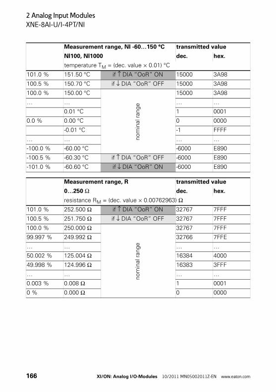
2 Analog Input Modules
XNE-8AI-U/I-4PT/NI
Measurement range, NI -60…150 °C transmitted value
NI100, NI1000 dec. hex.
temperature TM = (dec. value × 0.01) °C
101.0 % 151.50 °C if ↑ DIA “OoR” ON 15000 3A98
100.5 % 150.70 °C if ↓ DIA “OoR” OFF 15000 3A98
100.0 % 150.00 °C
nom
inal
ran
ge
15000 3A98
… … … …
0.01 °C 1 0001
0.0 % 0.00 °C 0 0000
-0.01 °C -1 FFFF
… … … …
-100.0 % -60.00 °C -6000 E890
-100.5 % -60.30 °C if ↑ DIA “OoR” OFF -6000 E890
-101.0 % -60.60 °C if ↓ DIA “OoR” ON -6000 E890
Measurement range, R transmitted value
0…250 Ω dec. hex.
resistance RM = (dec. value × 0.00762963) Ω101.0 % 252.500 Ω if ↑ DIA “OoR” ON 32767 7FFF
100.5 % 251.750 Ω if ↓ DIA “OoR” OFF 32767 7FFF
100.0 % 250.000 Ω
no
min
al r
ange
32767 7FFF
99.997 % 249.992 Ω 32766 7FFE
… … … …
50.002 % 125.004 Ω 16384 4000
49.998 % 124.996 Ω 16383 3FFF
… … … …
0.003 % 0.008 Ω 1 0001
0 % 0.000 Ω 0 0000
166 XI/ON: Analog I/O-Modules 10/2011 MN05002011Z-EN www.eaton.com
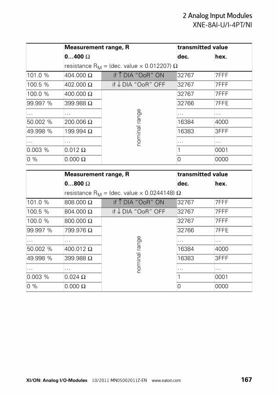
2 Analog Input Modules
XNE-8AI-U/I-4PT/NI
Measurement range, R transmitted value
0…400 Ω dec. hex.
resistance RM = (dec. value × 0.012207) Ω101.0 % 404.000 Ω if ↑ DIA “OoR” ON 32767 7FFF
100.5 % 402.000 Ω if ↓ DIA “OoR” OFF 32767 7FFF
100.0 % 400.000 Ω
nom
inal
ran
ge
32767 7FFF
99.997 % 399.988 Ω 32766 7FFE
… … … …
50.002 % 200.006 Ω 16384 4000
49.998 % 199.994 Ω 16383 3FFF
… … … …
0.003 % 0.012 Ω 1 0001
0 % 0.000 Ω 0 0000
Measurement range, R transmitted value
0…800 Ω dec. hex.
resistance RM = (dec. value × 0.0244148) Ω101.0 % 808.000 Ω if ↑ DIA “OoR” ON 32767 7FFF
100.5 % 804.000 Ω if ↓ DIA “OoR” OFF 32767 7FFF
100.0 % 800.000 Ω
nom
inal
ran
ge
32767 7FFF
99.997 % 799.976 Ω 32766 7FFE
… … … …
50.002 % 400.012 Ω 16384 4000
49.998 % 399.988 Ω 16383 3FFF
… … … …
0.003 % 0.024 Ω 1 0001
0 % 0.000 Ω 0 0000
XI/ON: Analog I/O-Modules 10/2011 MN05002011Z-EN www.eaton.com 167
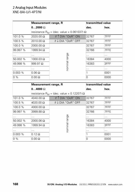
2 Analog Input Modules
XNE-8AI-U/I-4PT/NI
Measurement range, R transmitted value
0…2000 Ω dec. hex.
resistance RM = (dec. value × 0.061037) Ω101.0 % 2020.00 Ω if ↑ DIA “OoR” ON 32767 7FFF
100.5 % 2010.00 Ω if ↓ DIA “OoR” OFF 32767 7FFF
100.0 % 2000.00 Ω
nom
inal
ran
ge
32767 7FFF
99.997 % 1999.94 Ω 32766 7FFE
… … … …
50.002 % 1000.03 Ω 16384 4000
49.998 % 999.97 Ω 16383 3FFF
… … … …
0.003 % 0.06 Ω 1 0001
0 % 0.00 Ω 0 0000
Measurement range, R transmitted value
0…4000 Ω dec. hex.
resistance RM = (dec. value × 0.12207) Ω101.0 % 4040.00 Ω if ↑ DIA “OoR” ON 32767 7FFF
100.5 % 4020.00 Ω if ↓ DIA “OoR” OFF 32767 7FFF
100.0 % 4000.00 Ω
nom
inal
ran
ge
32767 7FFF
99.997 % 3999.88 Ω 32766 7FFE
… … … …
50.002 % 2000.06 Ω 16384 4000
49.998 % 1999.94 Ω 16383 3FFF
… … … …
0.003 % 0.12 Ω 1 0001
0 % 0.00 Ω 0 0000
168 XI/ON: Analog I/O-Modules 10/2011 MN05002011Z-EN www.eaton.com
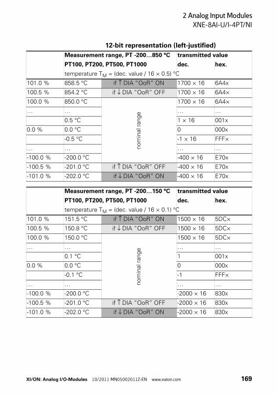
2 Analog Input Modules
XNE-8AI-U/I-4PT/NI
12-bit representation (left-justified)
Measurement range, PT -200…850 °C transmitted value
PT100, PT200, PT500, PT1000 dec. hex.
temperature TM = (dec. value / 16 × 0.5) °C
101.0 % 858.5 °C if ↑ DIA “OoR” ON 1700 × 16 6A4x
100.5 % 854.2 °C if ↓ DIA “OoR” OFF 1700 × 16 6A4×
100.0 % 850.0 °C
nom
inal
ran
ge
1700 × 16 6A4×
… … … …
0.5 °C 1 × 16 001x
0.0 % 0.0 °C 0 000x
-0.5 °C -1 × 16 FFF×
… … … …
-100.0 % -200.0 °C -400 × 16 E70x
-100.5 % -201.0 °C if ↑ DIA “OoR” OFF -400 × 16 E70x
-101.0 % -202.0 °C if ↓ DIA “OoR” ON -400 × 16 E70x
Measurement range, PT -200…150 °C transmitted value
PT100, PT200, PT500, PT1000 dec. hex.
temperature TM = (dec. value / 16 × 0.1) °C
101.0 % 151.5 °C if ↑ DIA “OoR” ON 1500 × 16 5DC×
100.5 % 150.8 °C if ↓ DIA “OoR” OFF 1500 × 16 5DC×
100.0 % 150.0 °C
nom
inal
ran
ge
1500 × 16 5DC×
… … … …
0.1 °C 1 001x
0.0 % 0.0 °C 0 000x
-0.1 °C -1 FFF×
… … … …
-100.0 % -200.0 °C -2000 × 16 830x
-100.5 % -201.0 °C if ↑ DIA “OoR” OFF -2000 × 16 830x
-101.0 % -202.0 °C if ↓ DIA “OoR” ON -2000 × 16 830x
XI/ON: Analog I/O-Modules 10/2011 MN05002011Z-EN www.eaton.com 169
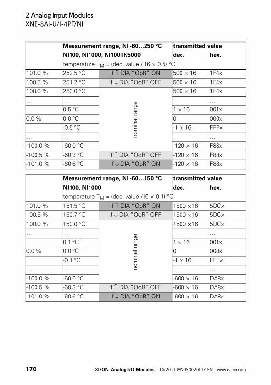
2 Analog Input Modules
XNE-8AI-U/I-4PT/NI
Measurement range, NI -60…250 °C transmitted value
NI100, NI1000, NI100TK5000 dec. hex.
temperature TM = (dec. value / 16 × 0.5) °C
101.0 % 252.5 °C if ↑ DIA “OoR” ON 500 × 16 1F4x
100.5 % 251.2 °C if ↓ DIA “OoR” OFF 500 × 16 1F4x
100.0 % 250.0 °C
nom
inal
ran
ge
500 × 16 1F4x
… … … …
0.5 °C 1 × 16 001x
0.0 % 0.0 °C 0 000x
-0.5 °C -1 × 16 FFF×
… … … …
-100.0 % -60.0 °C -120 × 16 F88x
-100.5 % -60.3 °C if ↑ DIA “OoR” OFF -120 × 16 F88x
-101.0 % -60.6 °C if ↓ DIA “OoR” ON -120 × 16 F88x
Measurement range, NI -60…150 °C transmitted value
NI100, NI1000 dec. hex.
temperature TM = (dec. value /16 × 0.1) °C
101.0 % 151.5 °C if ↑ DIA “OoR” ON 1500 ×16 5DC×
100.5 % 150.7 °C if ↓ DIA “OoR” OFF 1500 ×16 5DC×
100.0 % 150.0 °C
nom
inal
ran
ge
1500 ×16 5DC×
… … … …
0.1 °C 1 × 16 001x
0.0 % 0.0 °C 0 000x
-0.1 °C -1 × 16 FFF×
… … … …
-100.0 % -60.0 °C -600 × 16 DA8x
-100.5 % -60.3 °C if ↑ DIA “OoR” OFF -600 × 16 DA8x
-101.0 % -60.6 °C if ↓ DIA “OoR” ON -600 × 16 DA8x
170 XI/ON: Analog I/O-Modules 10/2011 MN05002011Z-EN www.eaton.com
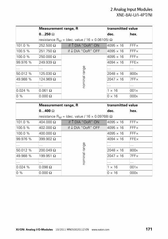
2 Analog Input Modules
XNE-8AI-U/I-4PT/NI
Measurement range, R transmitted value
0…250 Ω dec. hex.
resistance RM = (dec. value / 16 × 0.06105) Ω101.0 % 252.500 Ω if ↑ DIA “OoR” ON 4095 × 16 FFF×
100.5 % 251.750 Ω if ↓ DIA “OoR” OFF 4095 × 16 FFF×
100.0 % 250.000 Ω
nom
inal
ran
ge
4095 × 16 FFF×
99.976 % 249.939 Ω 4094 × 16 FFE×
… … … …
50.012 % 125.030 Ω 2048 × 16 800x
49.988 % 124.969 Ω 2047 × 16 7FF×
… … … …
0.024 % 0.061 Ω 1 × 16 001x
0 % 0.000 Ω 0 × 16 000x
Measurement range, R transmitted value
0…400 Ω dec. hex.
resistance RM = (dec. value / 16 × 0.09768) Ω101.0 % 404.000 Ω if ↑ DIA “OoR” ON 4095 × 16 FFF×
100.5 % 402.000 Ω if ↓ DIA “OoR” OFF 4095 × 16 FFF×
100.0 % 400.000 Ω
nom
inal
ran
ge
4095 × 16 FFF×
99.976 % 399.902 Ω 4094 × 16 FFE×
… … … …
50.012 % 200.049 Ω 2048 × 16 800x
49.988 % 199.951 Ω 2047 × 16 7FF×
… … … …
0.024 % 0.098 Ω 1 × 16 001x
0 % 0.000 Ω 0 × 16 000x
XI/ON: Analog I/O-Modules 10/2011 MN05002011Z-EN www.eaton.com 171
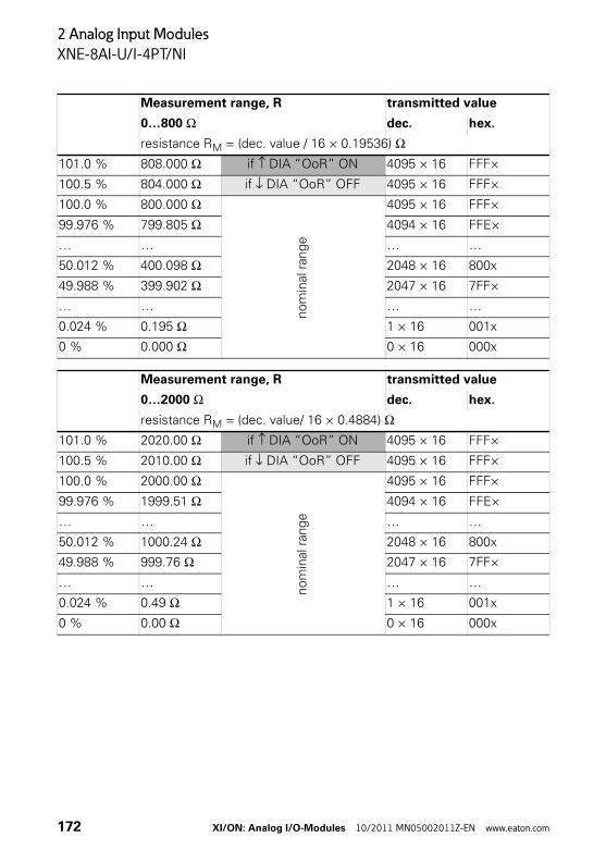
2 Analog Input Modules
XNE-8AI-U/I-4PT/NI
Measurement range, R transmitted value
0…800 Ω dec. hex.
resistance RM = (dec. value / 16 × 0.19536) Ω101.0 % 808.000 Ω if ↑ DIA “OoR” ON 4095 × 16 FFF×
100.5 % 804.000 Ω if ↓ DIA “OoR” OFF 4095 × 16 FFF×
100.0 % 800.000 Ω
nom
inal
ran
ge
4095 × 16 FFF×
99.976 % 799.805 Ω 4094 × 16 FFE×
… … … …
50.012 % 400.098 Ω 2048 × 16 800x
49.988 % 399.902 Ω 2047 × 16 7FF×
… … … …
0.024 % 0.195 Ω 1 × 16 001x
0 % 0.000 Ω 0 × 16 000x
Measurement range, R transmitted value
0…2000 Ω dec. hex.
resistance RM = (dec. value/ 16 × 0.4884) Ω101.0 % 2020.00 Ω if ↑ DIA “OoR” ON 4095 × 16 FFF×
100.5 % 2010.00 Ω if ↓ DIA “OoR” OFF 4095 × 16 FFF×
100.0 % 2000.00 Ω
nom
inal
ran
ge
4095 × 16 FFF×
99.976 % 1999.51 Ω 4094 × 16 FFE×
… … … …
50.012 % 1000.24 Ω 2048 × 16 800x
49.988 % 999.76 Ω 2047 × 16 7FF×
… … … …
0.024 % 0.49 Ω 1 × 16 001x
0 % 0.00 Ω 0 × 16 000x
172 XI/ON: Analog I/O-Modules 10/2011 MN05002011Z-EN www.eaton.com
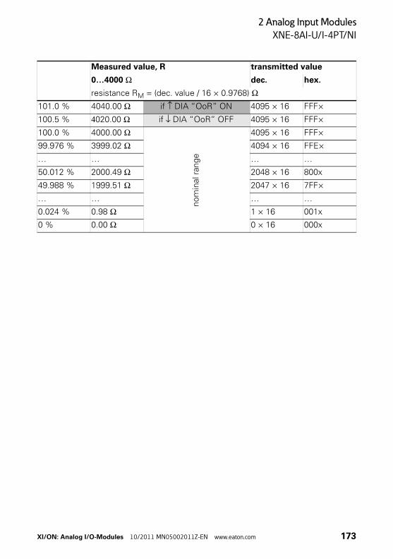
2 Analog Input Modules
XNE-8AI-U/I-4PT/NI
Measured value, R transmitted value
0…4000 Ω dec. hex.
resistance RM = (dec. value / 16 × 0.9768) Ω101.0 % 4040.00 Ω if ↑ DIA “OoR” ON 4095 × 16 FFF×
100.5 % 4020.00 Ω if ↓ DIA “OoR” OFF 4095 × 16 FFF×
100.0 % 4000.00 Ω
nom
inal
ran
ge
4095 × 16 FFF×
99.976 % 3999.02 Ω 4094 × 16 FFE×
… … … …
50.012 % 2000.49 Ω 2048 × 16 800x
49.988 % 1999.51 Ω 2047 × 16 7FF×
… … … …
0.024 % 0.98 Ω 1 × 16 001x
0 % 0.00 Ω 0 × 16 000x
XI/ON: Analog I/O-Modules 10/2011 MN05002011Z-EN www.eaton.com 173
2 Analog Input Modules
XNE-8AI-U/I-4PT/NI
174 XI/ON: Analog I/O-Modules 10/2011 MN05002011Z-EN www.eaton.com
3 Analog Output Modules
General
3 Analog Output Modules
General Analog output modules (AO) receive output values from the gateway via the internal module bus. The modules convert these values and transmit the appropriate signals per channel to the field level.
The electronics on the module bus of the analog output modules are isolated from the field level via optocouplers and are protected against reverse polarity.
The modules are short-circuit-proof.
Analog output modules are built in slice design. XN standard electronics modules are completed by base modules with tension clamp or screw connection. XNE ECO electronics modules do not require a base module.
Supported signal ranges0…20 mA,4…20 mA,0…10 V DC,-10…+10 V DC
Resolution of the analog value representationThe digitised analog values are represented in two's complement notation when both positive and negative values are processed. A parameter bit is used to set either 16-bit representation or left-justified 12-bit representation.
→ For the representation of current and voltage values with special operation modes (e.g. Extended Range and NE43) other equations and parameter settings must be applyed. Please read the subchapters «Value representation» of the corresponding module.
XI/ON: Analog I/O-Modules 10/2011 MN05002011Z-EN www.eaton.com 175
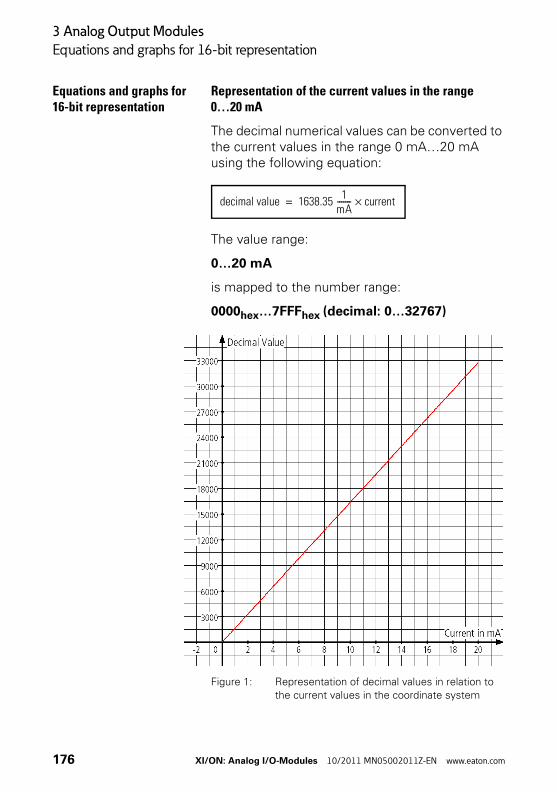
3 Analog Output Modules
Equations and graphs for 16-bit representation
Equations and graphs for 16-bit representation
Representation of the current values in the range0…20 mA
The decimal numerical values can be converted to the current values in the range 0 mA…20 mA using the following equation:
The value range:
0…20 mA
is mapped to the number range:
0000hex…7FFFhex (decimal: 0…32767)
Figure 1: Representation of decimal values in relation to
the current values in the coordinate system
decimal value 1638.35 1
mA------- current×=
176 XI/ON: Analog I/O-Modules 10/2011 MN05002011Z-EN www.eaton.com
3 Analog Output Modules
Equations and graphs for 16-bit representation
The decimal numerical value can be converted (using a pocket calculator) very easily to a hexadec-imal value since all the numbers are in the positive range of the two's complement (→ Figure 20 Page 39) of 16-bit values.
→ Make sure, the values which are to be trans-ferred to the device, are in the valid number range.
XI/ON: Analog I/O-Modules 10/2011 MN05002011Z-EN www.eaton.com 177
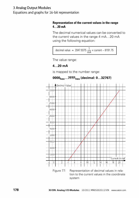
3 Analog Output Modules
Equations and graphs for 16-bit representation
Representation of the current values in the range4…20 mA
The decimal numerical values can be converted to the current values in the range 4 mA…20 mA using the following equation:
The value range:
4…20 mA
is mapped to the number range:
0000hex…7FFFhex (decimal: 0…32767)
Figure 77: Representation of decimal values in rela-tion to the current values in the coordinate system
decimal value 2047.9375 1
mA------- current 8191.75–×=
178 XI/ON: Analog I/O-Modules 10/2011 MN05002011Z-EN www.eaton.com

3 Analog Output Modules
Equations and graphs for 16-bit representation
The decimal numerical value can be converted (using a pocket calculator) very easily to a hexadec-imal value since all the numbers are in the positive range of the two's complement (→ Figure 20 Page 39) of 16-bit values.
→ Make sure, the values which are to be trans-ferred to the device, are in the valid number range.
XI/ON: Analog I/O-Modules 10/2011 MN05002011Z-EN www.eaton.com 179
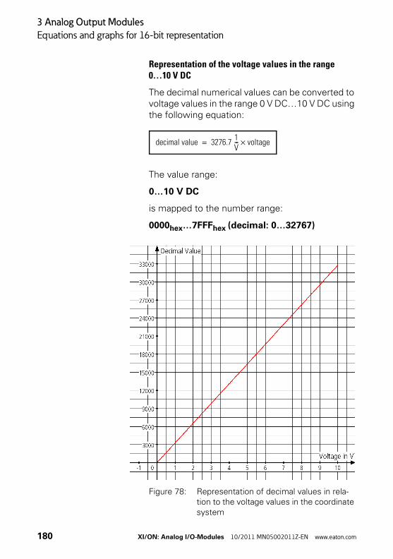
3 Analog Output Modules
Equations and graphs for 16-bit representation
Representation of the voltage values in the range0…10 V DC
The decimal numerical values can be converted to voltage values in the range 0 V DC…10 V DC using the following equation:
The value range:
0…10 V DC
is mapped to the number range:
0000hex…7FFFhex (decimal: 0…32767)
Figure 78: Representation of decimal values in rela-tion to the voltage values in the coordinate system
decimal value 3276.7 1V--- voltage×=
180 XI/ON: Analog I/O-Modules 10/2011 MN05002011Z-EN www.eaton.com

3 Analog Output Modules
Equations and graphs for 16-bit representation
The decimal numerical value can be converted (using a pocket calculator) very easily to a hexadec-imal value since all the numbers are in the positive range of the two's complement (→ Figure 20 Page 39) of 16-bit values.
→ Make sure, the values which are to be trans-ferred to the device, are in the valid number range.
XI/ON: Analog I/O-Modules 10/2011 MN05002011Z-EN www.eaton.com 181
3 Analog Output Modules
Equations and graphs for 16-bit representation
Representation of the voltage values in the range-10 V DC…10 V DC
The decimal numerical values can be converted to the voltage values in the range -10 V DC…10 V DC using the following equations:For positive voltage values 0 V DC…10 V DC:
The value range:
0…10 V DC
is mapped to the number range:
0000hex…7FFFhex (decimal: 0…32767)
For negative voltage values -10 V DC…0 V DC:
The value range:
-10…-3.052 10-4 V DC
is mapped to the number range:
8000hex…FFFFhex (decimal: -32768…-1)
decimal value 3276.7 1V--- voltage×=
decimal value 3276.8 1V--- voltage×=
182 XI/ON: Analog I/O-Modules 10/2011 MN05002011Z-EN www.eaton.com
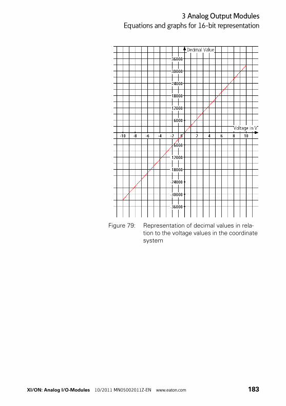
3 Analog Output Modules
Equations and graphs for 16-bit representation
Figure 79: Representation of decimal values in rela-tion to the voltage values in the coordinate system
XI/ON: Analog I/O-Modules 10/2011 MN05002011Z-EN www.eaton.com 183
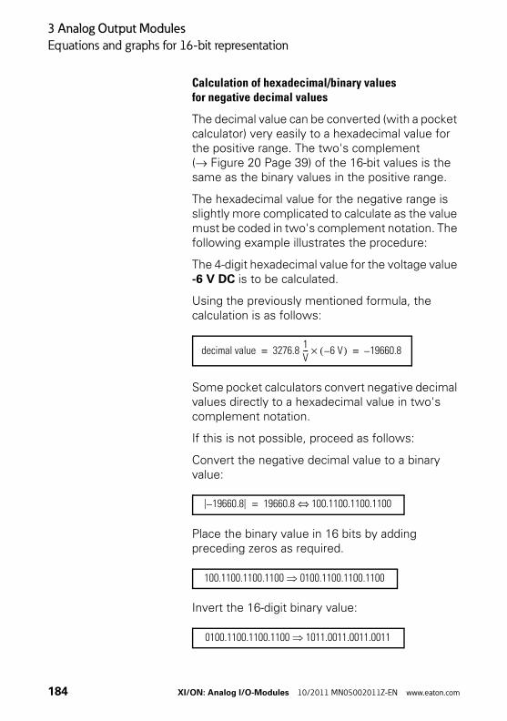
3 Analog Output Modules
Equations and graphs for 16-bit representation
Calculation of hexadecimal/binary valuesfor negative decimal values
The decimal value can be converted (with a pocket calculator) very easily to a hexadecimal value for the positive range. The two's complement (→ Figure 20 Page 39) of the 16-bit values is the same as the binary values in the positive range.
The hexadecimal value for the negative range is slightly more complicated to calculate as the value must be coded in two's complement notation. The following example illustrates the procedure:
The 4-digit hexadecimal value for the voltage value -6 V DC is to be calculated.
Using the previously mentioned formula, the calculation is as follows:
Some pocket calculators convert negative decimal values directly to a hexadecimal value in two's complement notation.
If this is not possible, proceed as follows:
Convert the negative decimal value to a binary value:
Place the binary value in 16 bits by adding preceding zeros as required.
Invert the 16-digit binary value:
decimal value 3276.8 1V--- 6 V–( )× 19660.8–= =
19660.8– 19660.8 100.1100.1100.1100⇔=
100.1100.1100.1100 0100.1100.1100.1100
0100.1100.1100.1100 1011.0011.0011.0011
184 XI/ON: Analog I/O-Modules 10/2011 MN05002011Z-EN www.eaton.com
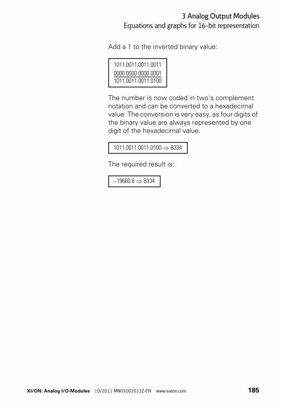
3 Analog Output Modules
Equations and graphs for 16-bit representation
Add a 1 to the inverted binary value:
The number is now coded in two's complement notation and can be converted to a hexadecimal value. The conversion is very easy, as four digits of the binary value are always represented by one digit of the hexadecimal value.
The required result is:
1011.0011.0011.0011
0000.0000.0000.00011011.0011.0011.0100----------------------------------------------
1011.0011.0011.0100 B334
19660.8– B334
XI/ON: Analog I/O-Modules 10/2011 MN05002011Z-EN www.eaton.com 185
3 Analog Output Modules
Equations and graphs for 12-bit representation
Equations and graphs for 12-bit representation
Attention!The 12-bit representation is “left-justified”. The number is transmitted with 16 bits! Bit 0…Bit 3 of the binary number and the last digit of the hexadecimal number are always 0.
186 XI/ON: Analog I/O-Modules 10/2011 MN05002011Z-EN www.eaton.com
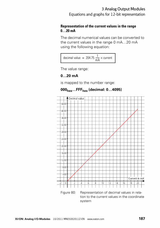
3 Analog Output Modules
Equations and graphs for 12-bit representation
Representation of the current values in the range0…20 mA
The decimal numerical values can be converted to the current values in the range 0 mA…20 mA using the following equation:
The value range:
0…20 mA
is mapped to the number range:
000hex…FFFhex (decimal: 0…4095)
Figure 80: Representation of decimal values in rela-tion to the current values in the coordinate system
decimal value 204.75 1
mA------- current×=
XI/ON: Analog I/O-Modules 10/2011 MN05002011Z-EN www.eaton.com 187
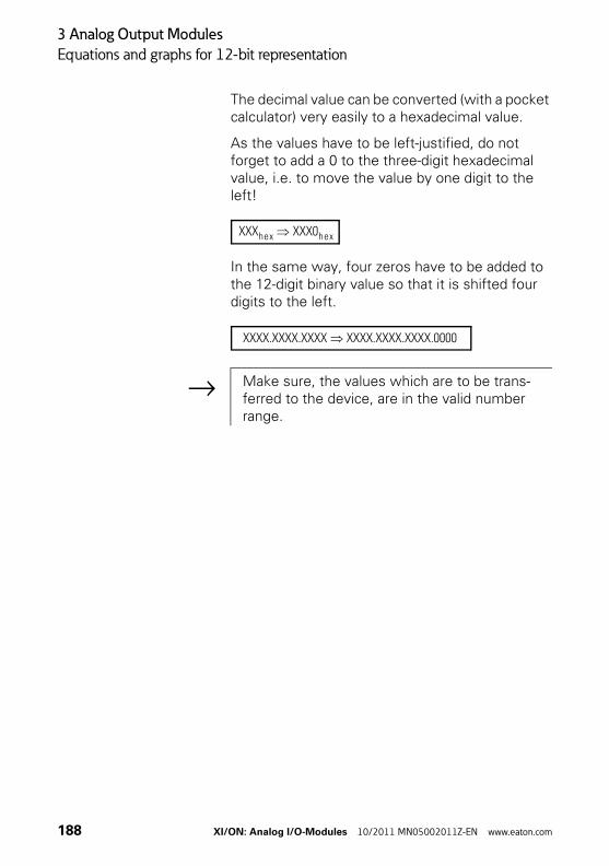
3 Analog Output Modules
Equations and graphs for 12-bit representation
The decimal value can be converted (with a pocket calculator) very easily to a hexadecimal value.
As the values have to be left-justified, do not forget to add a 0 to the three-digit hexadecimal value, i.e. to move the value by one digit to the left!
In the same way, four zeros have to be added to the 12-digit binary value so that it is shifted four digits to the left.
XXXhex XXX0hex
XXXX.XXXX.XXXX XXXX.XXXX.XXXX.0000
→ Make sure, the values which are to be trans-ferred to the device, are in the valid number range.
188 XI/ON: Analog I/O-Modules 10/2011 MN05002011Z-EN www.eaton.com
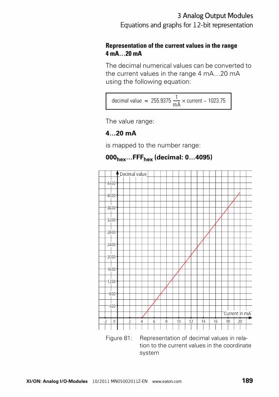
3 Analog Output Modules
Equations and graphs for 12-bit representation
Representation of the current values in the range4 mA…20 mA
The decimal numerical values can be converted to the current values in the range 4 mA…20 mA using the following equation:
The value range:
4…20 mA
is mapped to the number range:
000hex…FFFhex (decimal: 0…4095)
Figure 81: Representation of decimal values in rela-tion to the current values in the coordinate system
decimal value 255.9375 1
mA------- current 1023.75–×=
XI/ON: Analog I/O-Modules 10/2011 MN05002011Z-EN www.eaton.com 189

3 Analog Output Modules
Equations and graphs for 12-bit representation
The decimal value can be converted (with a pocket calculator) very easily to a hexadecimal value.
As the values have to be left-justified, do not forget to add a 0 to the three-digit hexadecimal value, i.e. to move the value by one digit to the left!
In the same way, four zeros have to be added to the 12-digit binary value so that it is shifted four digits to the left.
XXXhex XXX0hex
XXXX.XXXX.XXXX XXXX.XXXX.XXXX.0000
→ Make sure, the values which are to be trans-ferred to the device, are in the valid number range.
190 XI/ON: Analog I/O-Modules 10/2011 MN05002011Z-EN www.eaton.com
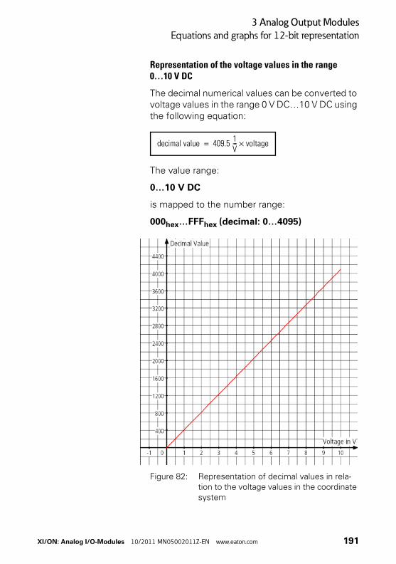
3 Analog Output Modules
Equations and graphs for 12-bit representation
Representation of the voltage values in the range0…10 V DC
The decimal numerical values can be converted to voltage values in the range 0 V DC…10 V DC using the following equation:
The value range:
0…10 V DC
is mapped to the number range:
000hex…FFFhex (decimal: 0…4095)
Figure 82: Representation of decimal values in rela-tion to the voltage values in the coordinate system
decimal value 409.5 1V--- voltage×=
XI/ON: Analog I/O-Modules 10/2011 MN05002011Z-EN www.eaton.com 191
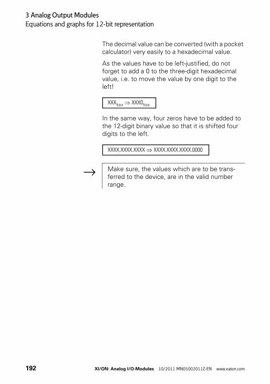
3 Analog Output Modules
Equations and graphs for 12-bit representation
The decimal value can be converted (with a pocket calculator) very easily to a hexadecimal value.
As the values have to be left-justified, do not forget to add a 0 to the three-digit hexadecimal value, i.e. to move the value by one digit to the left!
In the same way, four zeros have to be added to the 12-digit binary value so that it is shifted four digits to the left.
XXXhex XXX0hex
XXXX.XXXX.XXXX XXXX.XXXX.XXXX.0000
→ Make sure, the values which are to be trans-ferred to the device, are in the valid number range.
192 XI/ON: Analog I/O-Modules 10/2011 MN05002011Z-EN www.eaton.com
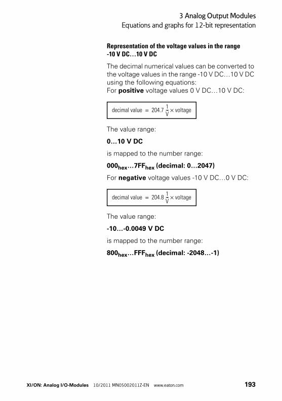
3 Analog Output Modules
Equations and graphs for 12-bit representation
Representation of the voltage values in the range-10 V DC…10 V DC
The decimal numerical values can be converted to the voltage values in the range -10 V DC…10 V DC using the following equations:For positive voltage values 0 V DC…10 V DC:
The value range:
0…10 V DC
is mapped to the number range:
000hex…7FFhex (decimal: 0…2047)
For negative voltage values -10 V DC…0 V DC:
The value range:
-10…-0.0049 V DC
is mapped to the number range:
800hex…FFFhex (decimal: -2048…-1)
decimal value 204.7 1V--- voltage×=
decimal value 204.8 1V--- voltage×=
XI/ON: Analog I/O-Modules 10/2011 MN05002011Z-EN www.eaton.com 193
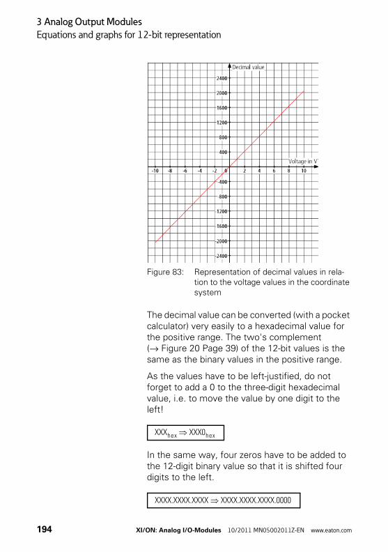
3 Analog Output Modules
Equations and graphs for 12-bit representation
Figure 83: Representation of decimal values in rela-tion to the voltage values in the coordinate system
The decimal value can be converted (with a pocket calculator) very easily to a hexadecimal value for the positive range. The two's complement (→ Figure 20 Page 39) of the 12-bit values is the same as the binary values in the positive range.
As the values have to be left-justified, do not forget to add a 0 to the three-digit hexadecimal value, i.e. to move the value by one digit to the left!
In the same way, four zeros have to be added to the 12-digit binary value so that it is shifted four digits to the left.
XXXhex XXX0hex
XXXX.XXXX.XXXX XXXX.XXXX.XXXX.0000
194 XI/ON: Analog I/O-Modules 10/2011 MN05002011Z-EN www.eaton.com
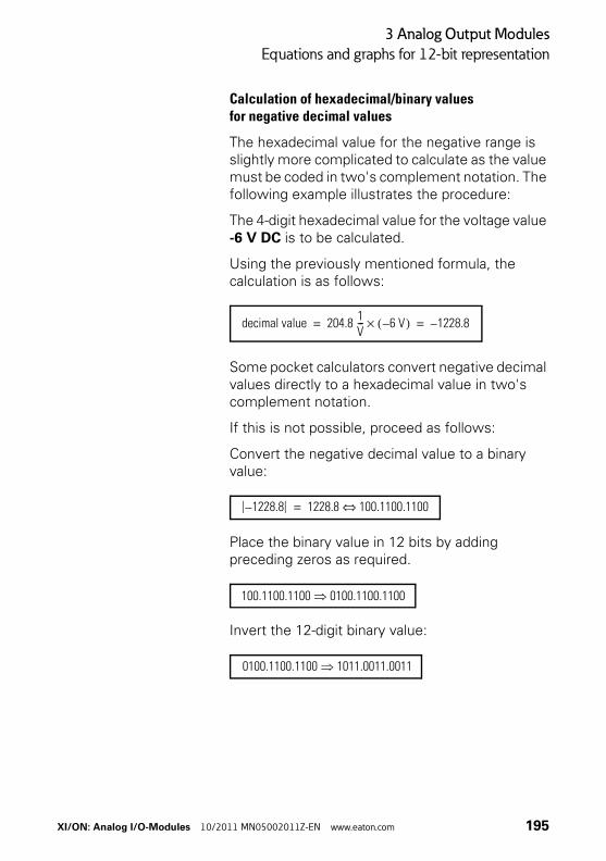
3 Analog Output Modules
Equations and graphs for 12-bit representation
Calculation of hexadecimal/binary valuesfor negative decimal values
The hexadecimal value for the negative range is slightly more complicated to calculate as the value must be coded in two's complement notation. The following example illustrates the procedure:
The 4-digit hexadecimal value for the voltage value -6 V DC is to be calculated.
Using the previously mentioned formula, the calculation is as follows:
Some pocket calculators convert negative decimal values directly to a hexadecimal value in two's complement notation.
If this is not possible, proceed as follows:
Convert the negative decimal value to a binary value:
Place the binary value in 12 bits by adding preceding zeros as required.
Invert the 12-digit binary value:
decimal value 204.8 1V--- 6 V–( )× 1228.8–= =
1228.8– 1228.8 100.1100.1100⇔=
100.1100.1100 0100.1100.1100
0100.1100.1100 1011.0011.0011
XI/ON: Analog I/O-Modules 10/2011 MN05002011Z-EN www.eaton.com 195
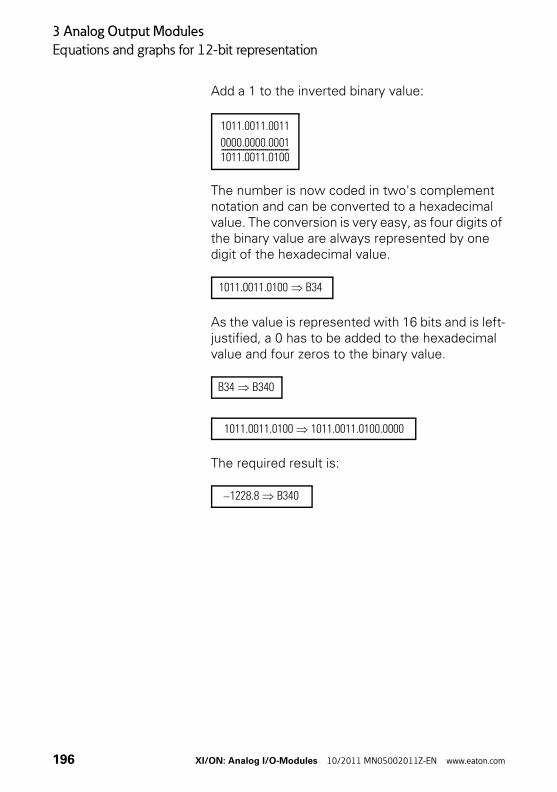
3 Analog Output Modules
Equations and graphs for 12-bit representation
Add a 1 to the inverted binary value:
The number is now coded in two's complement notation and can be converted to a hexadecimal value. The conversion is very easy, as four digits of the binary value are always represented by one digit of the hexadecimal value.
As the value is represented with 16 bits and is left-justified, a 0 has to be added to the hexadecimal value and four zeros to the binary value.
The required result is:
1011.0011.0011
0000.0000.00011011.0011.0100----------------------------------
1011.0011.0100 B34
B34 B340
1011.0011.0100 1011.0011.0100.0000
1228.8– B340
196 XI/ON: Analog I/O-Modules 10/2011 MN05002011Z-EN www.eaton.com
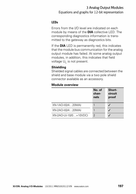
3 Analog Output Modules
Equations and graphs for 12-bit representation
LEDs
Errors from the I/O level are indicated on each module by means of the DIA collective LED. The corresponding diagnostics information is trans-mitted to the gateway as diagnostics bits.
If the DIA LED is permanently red, this indicates that the module bus communication for the analog output module has failed. At some analog output modules, in addition, this indicates that field voltage UL is not present.
ShieldingShielded signal cables are connected between the shield and base module via a two pole shield connector available as an accessory.
Module overview
No. of chan-nels
Short-circuit proof
XN-1AO-I(0/4…20MA) 1 ✓
XN-2AO-I(0/4…20MA) 1 ✓
XN-2AO-U(-10/0…+10VDC) 2 ✓
XI/ON: Analog I/O-Modules 10/2011 MN05002011Z-EN www.eaton.com 197
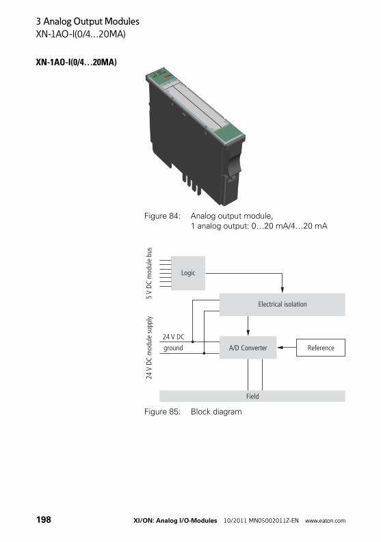
3 Analog Output Modules
XN-1AO-I(0/4…20MA)
XN-1AO-I(0/4…20MA)
Figure 84: Analog output module, 1 analog output: 0…20 mA/4…20 mA
Figure 85: Block diagram
Logic
24m
odul
e su
pply
V DC
5m
odul
e bu
sV
DC
Electrical isolation
Field
A/D Converter Reference
24 V DC
ground
198 XI/ON: Analog I/O-Modules 10/2011 MN05002011Z-EN www.eaton.com
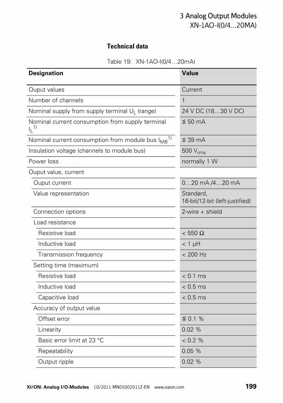
3 Analog Output Modules
XN-1AO-I(0/4…20MA)
Technical data
Table 19: XN-1AO-I(0/4…20mA)
Designation Value
Ouput values Current
Number of channels 1
Nominal supply from supply terminal UL (range) 24 V DC (18…30 V DC)
Nominal current consumption from supply terminal IL
1)≦ 50 mA
Nominal current consumption from module bus IMB1) ≦ 39 mA
Insulation voltage (channels to module bus) 500 Vrms
Power loss normally 1 W
Ouput value, current
Ouput current 0…20 mA /4…20 mA
Value representation Standard, 16-bit/12-bit (left-justified)
Connection options 2-wire + shield
Load resistance
Resistive load < 550 Ω
Inductive load < 1 μH
Transmission frequency < 200 Hz
Setting time (maximum)
Resistive load < 0.1 ms
Inductive load < 0.5 ms
Capacitive load < 0.5 ms
Accuracy of output value
Offset error ≦ 0.1 %
Linearity 0.02 %
Basic error limit at 23 °C < 0.2 %
Repeatability 0.05 %
Output ripple 0.02 %
XI/ON: Analog I/O-Modules 10/2011 MN05002011Z-EN www.eaton.com 199
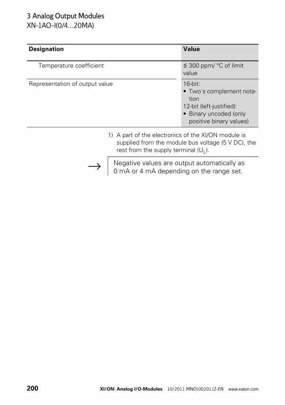
3 Analog Output Modules
XN-1AO-I(0/4…20MA)
1) A part of the electronics of the XI/ON module is supplied from the module bus voltage (5 V DC), the rest from the supply terminal (UL).
Temperature coefficient ≦ 300 ppm/ °C of limit value
Representation of output value 16-bit:• Two's complement nota-
tion12-bit (left-justified):• Binary uncoded (only
positive binary values)
Designation Value
→ Negative values are output automatically as 0 mA or 4 mA depending on the range set.
200 XI/ON: Analog I/O-Modules 10/2011 MN05002011Z-EN www.eaton.com

3 Analog Output Modules
XN-1AO-I(0/4…20MA)
Diagnostic messages
Module parameters
1) Standard parameter values
LED Display Meaning Remedy
DIA Red Failure of module bus communication
Check whether more than two adjacent electronics modules have been removed.
OFF No error message –
1AO0/4...20mA
DIA
Parameter name Value
Value representation Integer (15bit + sign)1)
12bit (left-justified)
Current mode 0..20mA1)
4..20mA
Substitute value A1 The substitute value defined here will be output if one of the specific events occurs which are parameterized in the gateway.
XI/ON: Analog I/O-Modules 10/2011 MN05002011Z-EN www.eaton.com 201
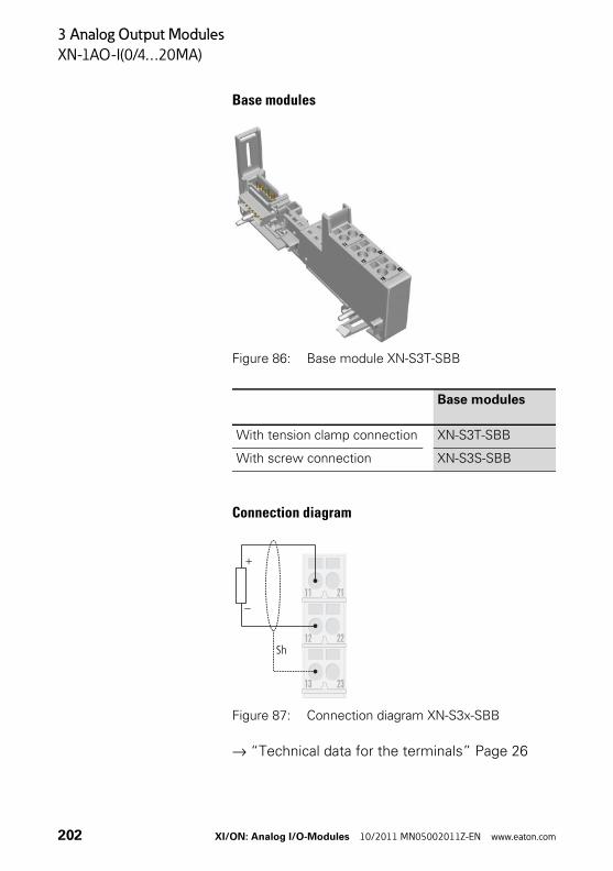
3 Analog Output Modules
XN-1AO-I(0/4…20MA)
Base modules
Figure 86: Base module XN-S3T-SBB
Connection diagram
Figure 87: Connection diagram XN-S3x-SBB
→ “Technical data for the terminals” Page 26
Base modules
With tension clamp connection XN-S3T-SBB
With screw connection XN-S3S-SBB
23
22
21
13
12
11
Sh
+
–
202 XI/ON: Analog I/O-Modules 10/2011 MN05002011Z-EN www.eaton.com
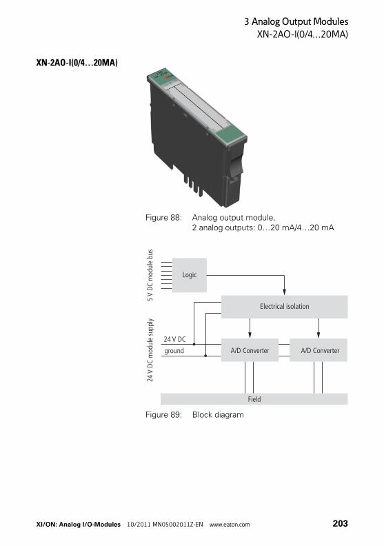
3 Analog Output Modules
XN-2AO-I(0/4…20MA)
XN-2AO-I(0/4…20MA)
Figure 88: Analog output module, 2 analog outputs: 0…20 mA/4…20 mA
Figure 89: Block diagram
Logic
24m
odul
e su
pply
V DC
5m
odul
e bu
sV
DC
Electrical isolation
Field
A/D Converter A/D Converter
24 V DC
ground
XI/ON: Analog I/O-Modules 10/2011 MN05002011Z-EN www.eaton.com 203
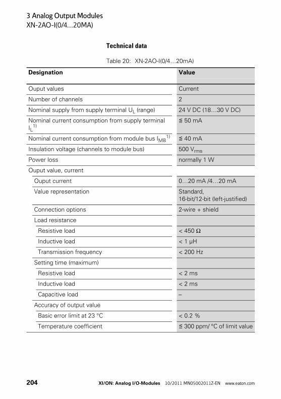
3 Analog Output Modules
XN-2AO-I(0/4…20MA)
Technical data
Table 20: XN-2AO-I(0/4…20mA)
Designation Value
Ouput values Current
Number of channels 2
Nominal supply from supply terminal UL (range) 24 V DC (18…30 V DC)
Nominal current consumption from supply terminal IL
1)≦ 50 mA
Nominal current consumption from module bus IMB1) ≦ 40 mA
Insulation voltage (channels to module bus) 500 Vrms
Power loss normally 1 W
Ouput value, current
Ouput current 0…20 mA /4…20 mA
Value representation Standard, 16-bit/12-bit (left-justified)
Connection options 2-wire + shield
Load resistance
Resistive load < 450 Ω
Inductive load < 1 μH
Transmission frequency < 200 Hz
Setting time (maximum)
Resistive load < 2 ms
Inductive load < 2 ms
Capacitive load –
Accuracy of output value
Basic error limit at 23 °C < 0.2 %
Temperature coefficient ≦ 300 ppm/ °C of limit value
204 XI/ON: Analog I/O-Modules 10/2011 MN05002011Z-EN www.eaton.com
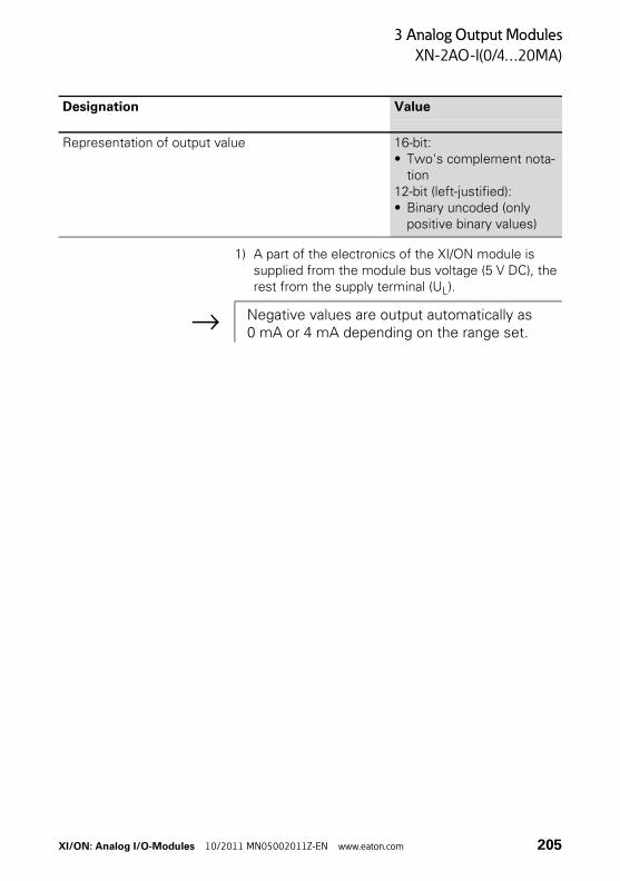
3 Analog Output Modules
XN-2AO-I(0/4…20MA)
1) A part of the electronics of the XI/ON module is supplied from the module bus voltage (5 V DC), the rest from the supply terminal (UL).
Representation of output value 16-bit:• Two's complement nota-
tion12-bit (left-justified):• Binary uncoded (only
positive binary values)
Designation Value
→ Negative values are output automatically as 0 mA or 4 mA depending on the range set.
XI/ON: Analog I/O-Modules 10/2011 MN05002011Z-EN www.eaton.com 205
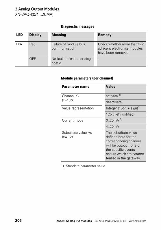
3 Analog Output Modules
XN-2AO-I(0/4…20MA)
Diagnostic messages
Module parameters (per channel)
1) Standard parameter value
LED Display Meaning Remedy
DIA Red Failure of module bus communication
Check whether more than two adjacent electronics modules have been removed.
OFF No fault indication or diag-nostic
-
Parameter name Value
Channel Kx(x=1,2)
activate 1)
deactivate
Value representation Integer (15bit + sign)1)
12bit (left-justified)
Current mode 0..20mA 1)
4..20mA
Substitute value Ax(x=1,2)
The substitute value defined here for the corresponding channel will be output if one of the specific events occurs which are parame-terized in the gateway.
206 XI/ON: Analog I/O-Modules 10/2011 MN05002011Z-EN www.eaton.com
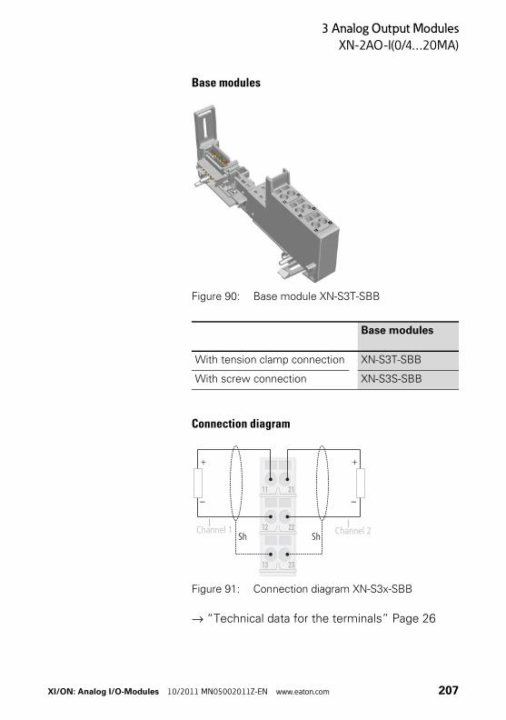
3 Analog Output Modules
XN-2AO-I(0/4…20MA)
Base modules
Figure 90: Base module XN-S3T-SBB
Connection diagram
Figure 91: Connection diagram XN-S3x-SBB
→ “Technical data for the terminals” Page 26
Base modules
With tension clamp connection XN-S3T-SBB
With screw connection XN-S3S-SBB
Channel 1 Channel 2
XI/ON: Analog I/O-Modules 10/2011 MN05002011Z-EN www.eaton.com 207
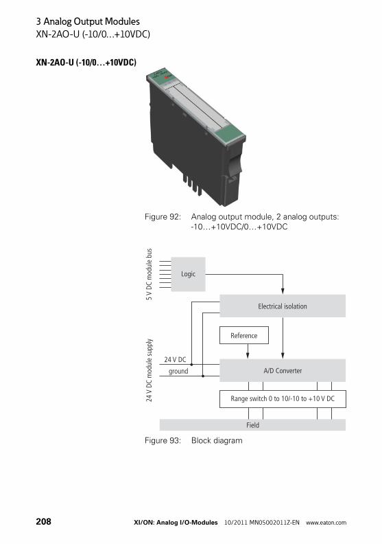
3 Analog Output Modules
XN-2AO-U (-10/0…+10VDC)
XN-2AO-U (-10/0…+10VDC)
Figure 92: Analog output module, 2 analog outputs: -10…+10VDC/0…+10VDC
Figure 93: Block diagram
Logic
24m
odul
e su
pply
V DC
5m
odul
e bu
sV
DC
Electrical isolation
Field
Range switch 0 to 10/-10 to +10 V DC
A/D Converter
Reference
24 V DC
ground
208 XI/ON: Analog I/O-Modules 10/2011 MN05002011Z-EN www.eaton.com
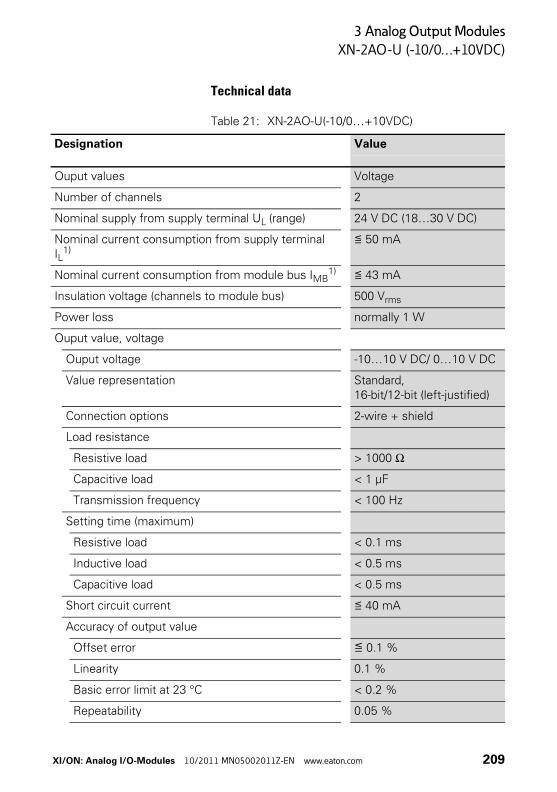
3 Analog Output Modules
XN-2AO-U (-10/0…+10VDC)
Technical data
Table 21: XN-2AO-U(-10/0…+10VDC)
Designation Value
Ouput values Voltage
Number of channels 2
Nominal supply from supply terminal UL (range) 24 V DC (18…30 V DC)
Nominal current consumption from supply terminal IL
1)≦ 50 mA
Nominal current consumption from module bus IMB1) ≦ 43 mA
Insulation voltage (channels to module bus) 500 Vrms
Power loss normally 1 W
Ouput value, voltage
Ouput voltage -10…10 V DC/ 0…10 V DC
Value representation Standard, 16-bit/12-bit (left-justified)
Connection options 2-wire + shield
Load resistance
Resistive load > 1000 Ω
Capacitive load < 1 μF
Transmission frequency < 100 Hz
Setting time (maximum)
Resistive load < 0.1 ms
Inductive load < 0.5 ms
Capacitive load < 0.5 ms
Short circuit current ≦ 40 mA
Accuracy of output value
Offset error ≦ 0.1 %
Linearity 0.1 %
Basic error limit at 23 °C < 0.2 %
Repeatability 0.05 %
XI/ON: Analog I/O-Modules 10/2011 MN05002011Z-EN www.eaton.com 209
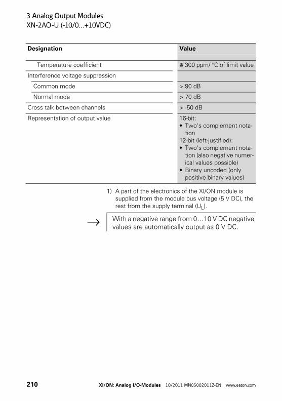
3 Analog Output Modules
XN-2AO-U (-10/0…+10VDC)
1) A part of the electronics of the XI/ON module is supplied from the module bus voltage (5 V DC), the rest from the supply terminal (UL).
Temperature coefficient ≦ 300 ppm/ °C of limit value
Interference voltage suppression
Common mode > 90 dB
Normal mode > 70 dB
Cross talk between channels > -50 dB
Representation of output value 16-bit:• Two's complement nota-
tion12-bit (left-justified):• Two's complement nota-
tion (also negative numer-ical values possible)
• Binary uncoded (only positive binary values)
Designation Value
→ With a negative range from 0…10 V DC negative values are automatically output as 0 V DC.
210 XI/ON: Analog I/O-Modules 10/2011 MN05002011Z-EN www.eaton.com
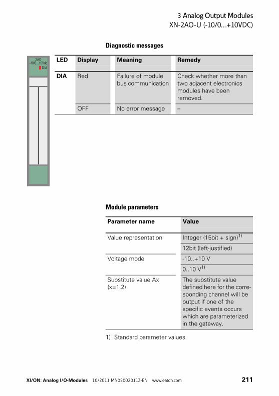
3 Analog Output Modules
XN-2AO-U (-10/0…+10VDC)
Diagnostic messages
Module parameters
1) Standard parameter values
LED Display Meaning Remedy
DIA Red Failure of module bus communication
Check whether more than two adjacent electronics modules have been removed.
OFF No error message –
2AO-10/0...10Vdc
DIA
Parameter name Value
Value representation Integer (15bit + sign)1)
12bit (left-justified)
Voltage mode -10..+10 V
0..10 V1)
Substitute value Ax(x=1,2)
The substitute value defined here for the corre-sponding channel will be output if one of the specific events occurs which are parameterized in the gateway.
XI/ON: Analog I/O-Modules 10/2011 MN05002011Z-EN www.eaton.com 211
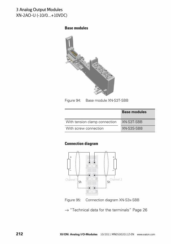
3 Analog Output Modules
XN-2AO-U (-10/0…+10VDC)
Base modules
Figure 94: Base module XN-S3T-SBB
Connection diagram
Figure 95: Connection diagram XN-S3x-SBB
→ “Technical data for the terminals” Page 26
Base modules
With tension clamp connection XN-S3T-SBB
With screw connection XN-S3S-SBB
Channel 1 Channel 2
212 XI/ON: Analog I/O-Modules 10/2011 MN05002011Z-EN www.eaton.com
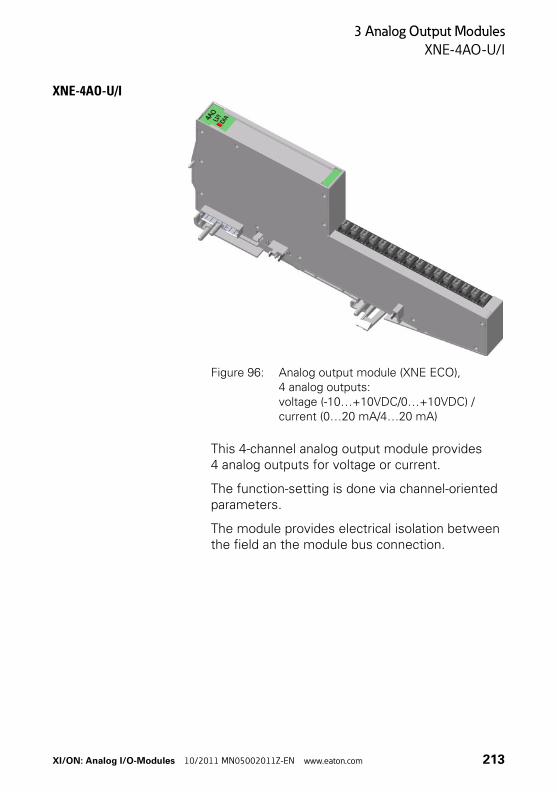
3 Analog Output Modules
XNE-4AO-U/I
XNE-4AO-U/I
Figure 96: Analog output module (XNE ECO), 4 analog outputs: voltage (-10…+10VDC/0…+10VDC) / current (0…20 mA/4…20 mA)
This 4-channel analog output module provides 4 analog outputs for voltage or current.
The function-setting is done via channel-oriented parameters.
The module provides electrical isolation between the field an the module bus connection.
XI/ON: Analog I/O-Modules 10/2011 MN05002011Z-EN www.eaton.com 213
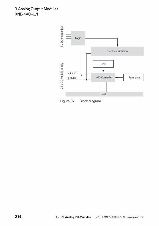
3 Analog Output Modules
XNE-4AO-U/I
Figure 97: Block diagram
Logic
24m
odul
e su
pply
V DC
5m
odul
e bu
sV
DC
Electrical isolation
A/D Converter Reference
24 V DC
ground
CPU
Field
214 XI/ON: Analog I/O-Modules 10/2011 MN05002011Z-EN www.eaton.com
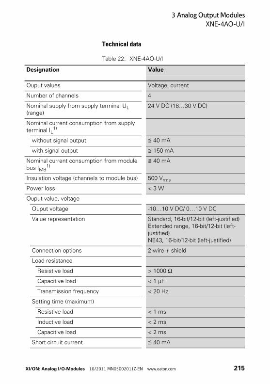
3 Analog Output Modules
XNE-4AO-U/I
Technical data
Table 22: XNE-4AO-U/I
Designation Value
Ouput values Voltage, current
Number of channels 4
Nominal supply from supply terminal UL (range)
24 V DC (18…30 V DC)
Nominal current consumption from supply terminal IL
1)
without signal output ≦ 40 mA
with signal output ≦ 150 mA
Nominal current consumption from module bus IMB
1)≦ 40 mA
Insulation voltage (channels to module bus) 500 Vrms
Power loss < 3 W
Ouput value, voltage
Ouput voltage -10…10 V DC/ 0…10 V DC
Value representation Standard, 16-bit/12-bit (left-justified)Extended range, 16-bit/12-bit (left-justified)NE43, 16-bit/12-bit (left-justified)
Connection options 2-wire + shield
Load resistance
Resistive load > 1000 Ω
Capacitive load < 1 μF
Transmission frequency < 20 Hz
Setting time (maximum)
Resistive load < 1 ms
Inductive load < 2 ms
Capacitive load < 2 ms
Short circuit current ≦ 40 mA
XI/ON: Analog I/O-Modules 10/2011 MN05002011Z-EN www.eaton.com 215
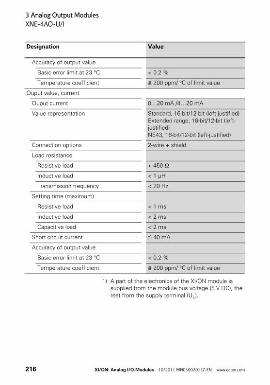
3 Analog Output Modules
XNE-4AO-U/I
1) A part of the electronics of the XI/ON module is supplied from the module bus voltage (5 V DC), the rest from the supply terminal (UL).
Accuracy of output value
Basic error limit at 23 °C < 0.2 %
Temperature coefficient ≦ 200 ppm/ °C of limit value
Ouput value, current
Ouput current 0…20 mA /4…20 mA
Value representation Standard, 16-bit/12-bit (left-justified)Extended range, 16-bit/12-bit (left-justified)NE43, 16-bit/12-bit (left-justified)
Connection options 2-wire + shield
Load resistance
Resistive load < 450 Ω
Inductive load < 1 μH
Transmission frequency < 20 Hz
Setting time (maximum)
Resistive load < 1 ms
Inductive load < 2 ms
Capacitive load < 2 ms
Short circuit current ≦ 40 mA
Accuracy of output value
Basic error limit at 23 °C < 0.2 %
Temperature coefficient ≦ 200 ppm/ °C of limit value
Designation Value
216 XI/ON: Analog I/O-Modules 10/2011 MN05002011Z-EN www.eaton.com
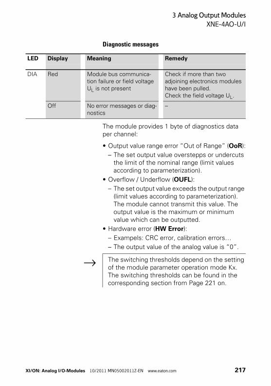
3 Analog Output Modules
XNE-4AO-U/I
Diagnostic messages
The module provides 1 byte of diagnostics data per channel:
• Output value range error “Out of Range” (OoR):
– The set output value overstepps or undercuts the limit of the nominal range (limit values according to parameterization).
• Overflow / Underflow (OUFL):
– The set output value exceeds the output range (limit values according to parameterization). The module cannot transmit this value. The output value is the maximum or minimum value which can be outputted.
• Hardware error (HW Error):
– Exampels: CRC error, calibration errors…
– The output value of the analog value is “0”.
LED Display Meaning Remedy
DIA Red Module bus communica-tion failure or field voltage UL is not present
Check if more than two adjoining electronics modules have been pulled.Check the field voltage UL.
Off No error messages or diag-nostics
–
→ The switching thresholds depend on the setting of the module parameter operation mode Kx. The switching thresholds can be found in the corresponding section from Page 221 on.
XI/ON: Analog I/O-Modules 10/2011 MN05002011Z-EN www.eaton.com 217
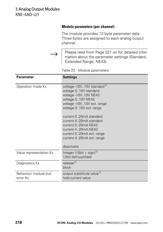
3 Analog Output Modules
XNE-4AO-U/I
Module parameters (per channel)
The module provides 12 byte parameter data. Three bytes are assigned to each analog output channel.
Table 23: Module parameters
→ Please read from Page 221 on for detailed infor-mation about the parameter settings (Standard, Extended Range, NE43).
Parameter Settings
Operation mode Kx voltage -10V..10V standard1) voltage 0..10V standardvoltage -10V..10V NE43voltage 0..10V NE43voltage -10V..10V ext. rangevoltage 0..10V ext. range
current 0..20mA standardcurrent 4..20mA standardcurrent 0..20mA NE43current 4..20mA NE43current 0..20mA ext. rangecurrent 4..20mA ext. range
deactivate
Value representation Kx Integer (15bit + sign)1) 12bit (left-justified)
Diagnostics Kx release1) block
Behaviour module bus error Ax
output substitute value1) hold current value
218 XI/ON: Analog I/O-Modules 10/2011 MN05002011Z-EN www.eaton.com
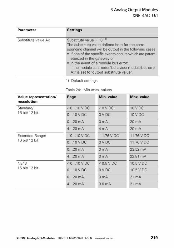
3 Analog Output Modules
XNE-4AO-U/I
1) Default settings
Table 24: Min./max. values
Substitute value Ax Substitute value = “0“1) The substitute value defined here for the corre-sponding channel will be output in the following cases:• if one of the specific events occurs which are param-
eterized in the gateway or• in the event of a module bus error:
if the module parameter "behaviour module bus error Ax" is set to "output substitute value".
Parameter Settings
Value representation/ ressolution
Rage Min. value Max. value
Standard/16 bit/ 12 bit
-10…10 V DC -10 V DC 10 V DC
0…10 V DC 0 V DC 10 V DC
0…20 mA 0 mA 20 mA
4…20 mA 4 mA 20 mA
Extended Range/ 16 bit/ 12 bit
-10…10 V DC -11.76 V DC 11.76 V DC
0…10 V DC 0 V DC 11.76 V DC
0…20 mA 0 mA 23.52 mA
4…20 mA 0 mA 22.81 mA
NE4316 bit/ 12 bit
-10…10 V DC -10.5 V DC 10.5 V DC
0…10 V DC 0 V DC 10.5 V DC
0…20 mA 0 mA 21 mA
4…20 mA 3.6 mA 21 mA
XI/ON: Analog I/O-Modules 10/2011 MN05002011Z-EN www.eaton.com 219
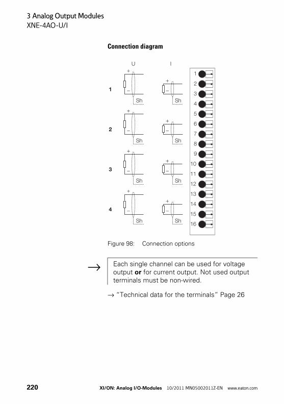
3 Analog Output Modules
XNE-4AO-U/I
Connection diagram
Figure 98: Connection options
→ “Technical data for the terminals” Page 26
�
�
�
�
�
�
�
��
��
��
��
��
��
��
�
�
��
�
��
�
��
�
��
�
��
�
��
�
��
�
��
�
�
�
� �
→ Each single channel can be used for voltage output or for current output. Not used output terminals must be non-wired.
220 XI/ON: Analog I/O-Modules 10/2011 MN05002011Z-EN www.eaton.com
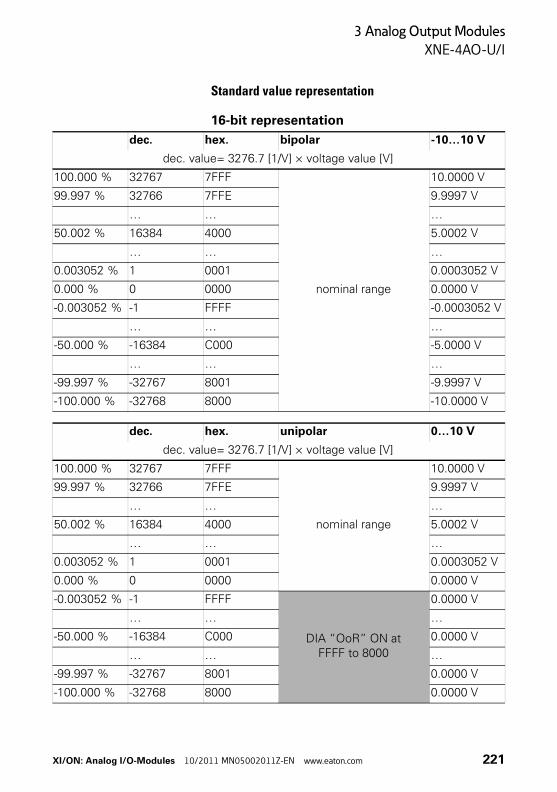
3 Analog Output Modules
XNE-4AO-U/I
Standard value representation
16-bit representation
dec. hex. bipolar -10…10 V
dec. value= 3276.7 [1/V] × voltage value [V]
100.000 % 32767 7FFF
nominal range
10.0000 V
99.997 % 32766 7FFE 9.9997 V
… … …
50.002 % 16384 4000 5.0002 V
… … …
0.003052 % 1 0001 0.0003052 V
0.000 % 0 0000 0.0000 V
-0.003052 % -1 FFFF -0.0003052 V
… … …
-50.000 % -16384 C000 -5.0000 V
… … …
-99.997 % -32767 8001 -9.9997 V
-100.000 % -32768 8000 -10.0000 V
dec. hex. unipolar 0…10 V
dec. value= 3276.7 [1/V] × voltage value [V]
100.000 % 32767 7FFF
nominal range
10.0000 V
99.997 % 32766 7FFE 9.9997 V
… … …
50.002 % 16384 4000 5.0002 V
… … …
0.003052 % 1 0001 0.0003052 V
0.000 % 0 0000 0.0000 V
-0.003052 % -1 FFFF
DIA “OoR” ON at FFFF to 8000
0.0000 V
… … …
-50.000 % -16384 C000 0.0000 V
… … …
-99.997 % -32767 8001 0.0000 V
-100.000 % -32768 8000 0.0000 V
XI/ON: Analog I/O-Modules 10/2011 MN05002011Z-EN www.eaton.com 221
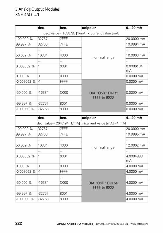
3 Analog Output Modules
XNE-4AO-U/I
dec. hex. unipolar 0…20 mA
dec. value= 1638.35 [1/mA] × current value [mA]
100.000 % 32767 7FFF
nominal range
20.0000 mA
99.997 % 32766 7FFE 19.9994 mA
… … …
50.002 % 16384 4000 10.0003 mA
… … …
0.003052 % 1 0001 0.0006104 mA
0.000 % 0 0000 0.0000 mA
-0.003052 % -1 FFFF
DIA “OoR” EIN at FFFF to 8000
0.0000 mA
… … …
-50.000 % -16384 C000 0.0000 mA
… … …
-99.997 % -32767 8001 0.0000 mA
-100.000 % -32768 8000 0.0000 mA
dec. hex. unipolar 4…20 mA
dec. value= 2047.94 [1/mA] × (current value [mA] - 4 mA)
100.000 % 32767 7FFF
nominal range
20.0000 mA
99.997 % 32766 7FFE 19.9995 mA
… … …
50.002 % 16384 4000 12.0002 mA
… … …
0.003052 % 1 0001 4.0004883 mA
0.000 % 0 0000 4.0000 mA
-0.003052 % -1 FFFF
DIA “OoR” EIN bei FFFF to 8000
4.0000 mA
… … …
-50.000 % -16384 C000 4.0000 mA
… … …
-99.997 % -32767 8001 4.0000 mA
-100.000 % -32768 8000 4.0000 mA
222 XI/ON: Analog I/O-Modules 10/2011 MN05002011Z-EN www.eaton.com
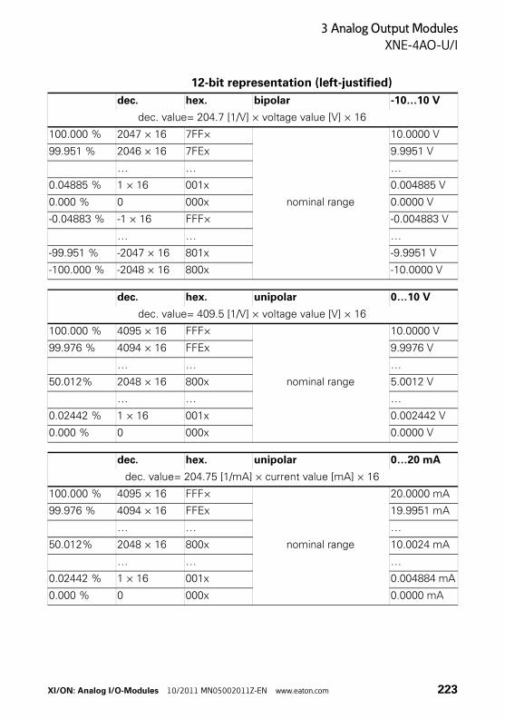
3 Analog Output Modules
XNE-4AO-U/I
12-bit representation (left-justified)
dec. hex. bipolar -10…10 V
dec. value= 204.7 [1/V] × voltage value [V] × 16
100.000 % 2047 × 16 7FF×
nominal range
10.0000 V
99.951 % 2046 × 16 7FEx 9.9951 V
… … …
0.04885 % 1 × 16 001x 0.004885 V
0.000 % 0 000x 0.0000 V
-0.04883 % -1 × 16 FFF× -0.004883 V
… … …
-99.951 % -2047 × 16 801x -9.9951 V
-100.000 % -2048 × 16 800x -10.0000 V
dec. hex. unipolar 0…10 V
dec. value= 409.5 [1/V] × voltage value [V] × 16
100.000 % 4095 × 16 FFF×
nominal range
10.0000 V
99.976 % 4094 × 16 FFEx 9.9976 V
… … …
50.012% 2048 × 16 800x 5.0012 V
… … …
0.02442 % 1 × 16 001x 0.002442 V
0.000 % 0 000x 0.0000 V
dec. hex. unipolar 0…20 mA
dec. value= 204.75 [1/mA] × current value [mA] × 16
100.000 % 4095 × 16 FFF×
nominal range
20.0000 mA
99.976 % 4094 × 16 FFEx 19.9951 mA
… … …
50.012% 2048 × 16 800x 10.0024 mA
… … …
0.02442 % 1 × 16 001x 0.004884 mA
0.000 % 0 000x 0.0000 mA
XI/ON: Analog I/O-Modules 10/2011 MN05002011Z-EN www.eaton.com 223
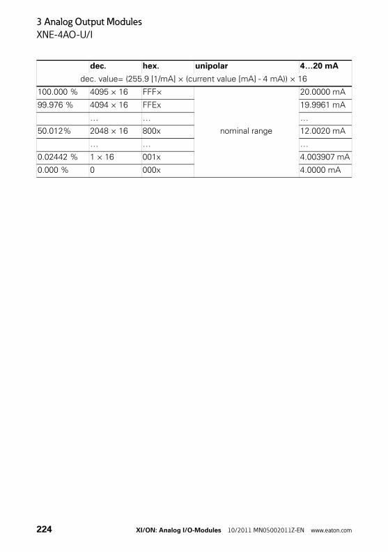
3 Analog Output Modules
XNE-4AO-U/I
dec. hex. unipolar 4…20 mA
dec. value= (255.9 [1/mA] × (current value [mA] - 4 mA)) × 16
100.000 % 4095 × 16 FFF×
nominal range
20.0000 mA
99.976 % 4094 × 16 FFEx 19.9961 mA
… … …
50.012% 2048 × 16 800x 12.0020 mA
… … …
0.02442 % 1 × 16 001x 4.003907 mA
0.000 % 0 000x 4.0000 mA
224 XI/ON: Analog I/O-Modules 10/2011 MN05002011Z-EN www.eaton.com
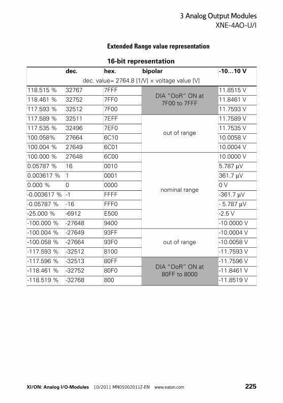
3 Analog Output Modules
XNE-4AO-U/I
Extended Range value representation
16-bit representation
dec. hex. bipolar -10…10 V
dec. value= 2764.8 [1/V] × voltage value [V]
118.515 % 32767 7FFFDIA “OoR” ON at
7F00 to 7FFF
11.8515 V
118.461 % 32752 7FF0 11.8461 V
117.593 % 32512 7F00 11.7593 V
117.589 % 32511 7EFF
out of range
11.7589 V
117.535 % 32496 7EF0 11.7535 V
100.058% 27664 6C10 10.0058 V
100.004 % 27649 6C01 10.0004 V
100.000 % 27648 6C00
nominal range
10.0000 V
0.05787 % 16 0010 5.787 μV
0.003617 % 1 0001 361.7 μV
0.000 % 0 0000 0 V
-0.003617 % -1 FFFF -361.7 μV
-0.05787 % -16 FFF0 - 5.787 μV
-25.000 % -6912 E500 -2.5 V
-100.000 % -27648 9400 -10.0000 V
-100.004 % -27649 93FF
out of range
-10.0004 V
-100.058 % -27664 93F0 -10.0058 V
-117.593 % -32512 8100 -11.7593 V
-117.596 % -32513 80FFDIA “OoR” ON at
80FF to 8000
-11.7596 V
-118.461 % -32752 80F0 -11.8461 V
-118.519 % -32768 800 -11.8519 V
XI/ON: Analog I/O-Modules 10/2011 MN05002011Z-EN www.eaton.com 225
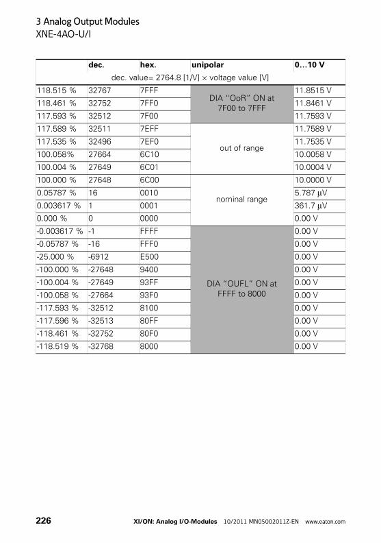
3 Analog Output Modules
XNE-4AO-U/I
dec. hex. unipolar 0…10 V
dec. value= 2764.8 [1/V] × voltage value [V]
118.515 % 32767 7FFFDIA “OoR” ON at
7F00 to 7FFF
11.8515 V
118.461 % 32752 7FF0 11.8461 V
117.593 % 32512 7F00 11.7593 V
117.589 % 32511 7EFF
out of range
11.7589 V
117.535 % 32496 7EF0 11.7535 V
100.058% 27664 6C10 10.0058 V
100.004 % 27649 6C01 10.0004 V
100.000 % 27648 6C00
nominal range
10.0000 V
0.05787 % 16 0010 5.787 μV
0.003617 % 1 0001 361.7 μV
0.000 % 0 0000 0.00 V
-0.003617 % -1 FFFF
DIA “OUFL” ON at FFFF to 8000
0.00 V
-0.05787 % -16 FFF0 0.00 V
-25.000 % -6912 E500 0.00 V
-100.000 % -27648 9400 0.00 V
-100.004 % -27649 93FF 0.00 V
-100.058 % -27664 93F0 0.00 V
-117.593 % -32512 8100 0.00 V
-117.596 % -32513 80FF 0.00 V
-118.461 % -32752 80F0 0.00 V
-118.519 % -32768 8000 0.00 V
226 XI/ON: Analog I/O-Modules 10/2011 MN05002011Z-EN www.eaton.com
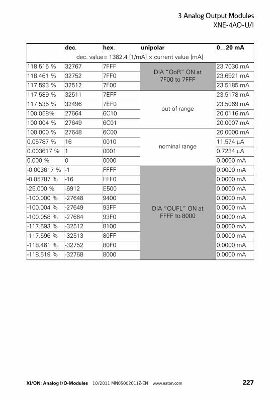
3 Analog Output Modules
XNE-4AO-U/I
dec. hex. unipolar 0…20 mA
dec. value= 1382.4 [1/mA] × current value [mA]
118.515 % 32767 7FFFDIA “OoR” ON at
7F00 to 7FFF
23.7030 mA
118.461 % 32752 7FF0 23.6921 mA
117.593 % 32512 7F00 23.5185 mA
117.589 % 32511 7EFF
out of range
23.5178 mA
117.535 % 32496 7EF0 23.5069 mA
100.058% 27664 6C10 20.0116 mA
100.004 % 27649 6C01 20.0007 mA
100.000 % 27648 6C00
nominal range
20.0000 mA
0.05787 % 16 0010 11.574 μA
0.003617 % 1 0001 0.7234 μA
0.000 % 0 0000 0.0000 mA
-0.003617 % -1 FFFF
DIA “OUFL” ON at FFFF to 8000
0.0000 mA
-0.05787 % -16 FFF0 0.0000 mA
-25.000 % -6912 E500 0.0000 mA
-100.000 % -27648 9400 0.0000 mA
-100.004 % -27649 93FF 0.0000 mA
-100.058 % -27664 93F0 0.0000 mA
-117.593 % -32512 8100 0.0000 mA
-117.596 % -32513 80FF 0.0000 mA
-118.461 % -32752 80F0 0.0000 mA
-118.519 % -32768 8000 0.0000 mA
XI/ON: Analog I/O-Modules 10/2011 MN05002011Z-EN www.eaton.com 227
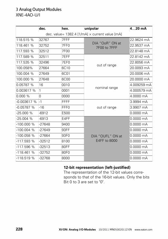
3 Analog Output Modules
XNE-4AO-U/I
12-bit representation (left-justified)The representation of the 12-bit values corre-sponds to that of the 16-bit values. Only the bits Bit 0 to 3 are set to "0".
dec. hex. unipolar 4…20 mA
dec. value= 1382.4 [1/mA] × current value [mA]
118.515 % 32767 7FFFDIA “OoR” ON at
7F00 to 7FFF
22.9624 mA
118.461 % 32752 7FF0 22.9537 mA
117.593 % 32512 7F00 22.8148 mA
117.589 % 32511 7EFF
out of range
22.8142 mA
117.535 % 32496 7EF0 22.8056 mA
100.058% 27664 6C10 20.0093 mA
100.004 % 27649 6C01 20.0006 mA
100.000 % 27648 6C00
nominal range
20.0000 mA
0.05787 % 16 0010 4.009259 mA
0.003617 % 1 0001 4.000579 mA
0.000 % 0 0000 4.0000 mA
-0.003617 % -1 FFFF
out of range
3.9994 mA
-0.05787 % -16 FFF0 3.9907 mA
-25.000 % -6912 E500 0.0000 mA
-25.004 % -6913 E4FF
DIA “OUFL” ON at E4FF to 8000
0.0000 mA
-100.000 % -27648 9400 0.0000 mA
-100.004 % -27649 93FF 0.0000 mA
-100.058 % -27664 93F0 0.0000 mA
-117.593 % -32512 8100 0.0000 mA
-117.596 % -32513 80FF 0.0000 mA
-118.461 % -32752 80F0 0.0000 mA
-118.519 % -32768 8000 0.0000 mA
228 XI/ON: Analog I/O-Modules 10/2011 MN05002011Z-EN www.eaton.com
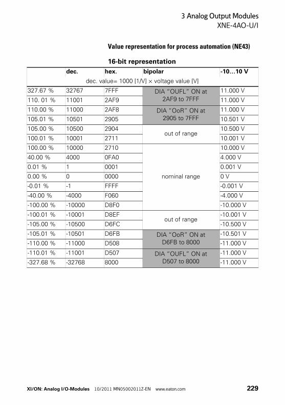
3 Analog Output Modules
XNE-4AO-U/I
Value representation for process automation (NE43)
16-bit representation
dec. hex. bipolar -10…10 V
dec. value= 1000 [1/V] × voltage value [V]
327.67 % 32767 7FFF DIA “OUFL” ON at 2AF9 to 7FFF
11.000 V
110. 01 % 11001 2AF9 11.000 V
110.00 % 11000 2AF8 DIA “OoR” ON at 2905 to 7FFF
11.000 V
105.01 % 10501 2905 10.501 V
105.00 % 10500 2904out of range
10.500 V
100.01 % 10001 2711 10.001 V
100.00 % 10000 2710
nominal range
10.000 V
40.00 % 4000 0FA0 4.000 V
0.01 % 1 0001 0.001 V
0.00 % 0 0000 0 V
-0.01 % -1 FFFF -0.001 V
-40.00 % -4000 F060 -4.000 V
-100.00 % -10000 D8F0 -10.000 V
-100.01 % -10001 D8EFout of range
-10.001 V
-105.00 % -10500 D6FC -10.500 V
-105.01 % -10501 D6FB DIA “OoR” ON at D6FB to 8000
-10.501 V
-110.00 % -11000 D508 -11.000 V
-110.01 % -11001 D507 DIA “OUFL” ON at D507 to 8000
-11.000 V
-327.68 % -32768 8000 -11.000 V
XI/ON: Analog I/O-Modules 10/2011 MN05002011Z-EN www.eaton.com 229
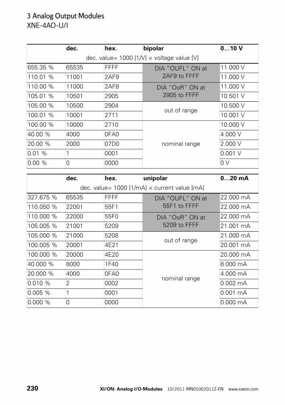
3 Analog Output Modules
XNE-4AO-U/I
dec. hex. bipolar 0…10 V
dec. value= 1000 [1/V] × voltage value [V]
655.35 % 65535 FFFF DIA “OUFL” ON at 2AF9 to FFFF
11.000 V
110.01 % 11001 2AF9 11.000 V
110.00 % 11000 2AF8 DIA “OoR” ON at 2905 to FFFF
11.000 V
105.01 % 10501 2905 10.501 V
105.00 % 10500 2904out of range
10.500 V
100.01 % 10001 2711 10.001 V
100.00 % 10000 2710
nominal range
10.000 V
40.00 % 4000 0FA0 4.000 V
20.00 % 2000 07D0 2.000 V
0.01 % 1 0001 0.001 V
0.00 % 0 0000 0 V
dec. hex. unipolar 0…20 mA
dec. value= 1000 [1/mA] × current value [mA]
327.675 % 65535 FFFF DIA “OUFL” ON at 55F1 to FFFF
22.000 mA
110.050 % 22001 55F1 22.000 mA
110.000 % 22000 55F0 DIA “OoR” ON at 5209 to FFFF
22.000 mA
105.005 % 21001 5209 21.001 mA
105.000 % 21000 5208out of range
21.000 mA
100.005 % 20001 4E21 20.001 mA
100.000 % 20000 4E20
nominal range
20.000 mA
40.000 % 8000 1F40 8.000 mA
20.000 % 4000 0FA0 4.000 mA
0.010 % 2 0002 0.002 mA
0.005 % 1 0001 0.001 mA
0.000 % 0 0000 0.000 mA
230 XI/ON: Analog I/O-Modules 10/2011 MN05002011Z-EN www.eaton.com
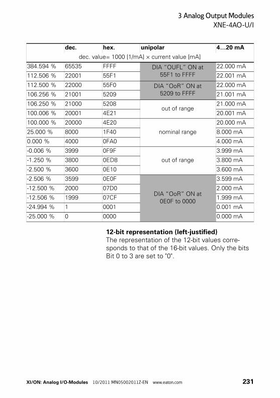
3 Analog Output Modules
XNE-4AO-U/I
12-bit representation (left-justified)The representation of the 12-bit values corre-sponds to that of the 16-bit values. Only the bits Bit 0 to 3 are set to "0".
dec. hex. unipolar 4…20 mA
dec. value= 1000 [1/mA] × current value [mA]
384.594 % 65535 FFFF DIA “OUFL” ON at 55F1 to FFFF
22.000 mA
112.506 % 22001 55F1 22.001 mA
112.500 % 22000 55F0 DIA “OoR” ON at 5209 to FFFF
22.000 mA
106.256 % 21001 5209 21.001 mA
106.250 % 21000 5208out of range
21.000 mA
100.006 % 20001 4E21 20.001 mA
100.000 % 20000 4E20
nominal range
20.000 mA
25.000 % 8000 1F40 8.000 mA
0.000 % 4000 0FA0 4.000 mA
-0.006 % 3999 0F9F
out of range
3.999 mA
-1.250 % 3800 0ED8 3.800 mA
-2.500 % 3600 0E10 3.600 mA
-2.506 % 3599 0E0F
DIA “OoR” ON at 0E0F to 0000
3.599 mA
-12.500 % 2000 07D0 2.000 mA
-12.506 % 1999 07CF 1.999 mA
-24.994 % 1 0001 0.001 mA
-25.000 % 0 0000 0.000 mA
XI/ON: Analog I/O-Modules 10/2011 MN05002011Z-EN www.eaton.com 231
3 Analog Output Modules
XNE-4AO-U/I
232 XI/ON: Analog I/O-Modules 10/2011 MN05002011Z-EN www.eaton.com
4 Integration in PROFIBUS-DP
General
4 Integration in PROFIBUS-DP
General The process data is transmitted byte-wise (8-bit) via PROFIBUS. The analog module types have 2 bytes of process data for each channel. The two process data bytes contain the measured value of the channel and define the voltage or current value of the channel.
The analog input modules supply process input data and the diagnostics data if the appropriate parameter is set (12-bit representation).
The analog output modules and relay modules only receive process output data.
→ You can find the latest GSD files on our home page (www.eaton-automation.com),under „DOWNLOADS“.
XI/ON: Analog I/O-Modules 10/2011 MN05002011Z-EN www.eaton.com 233
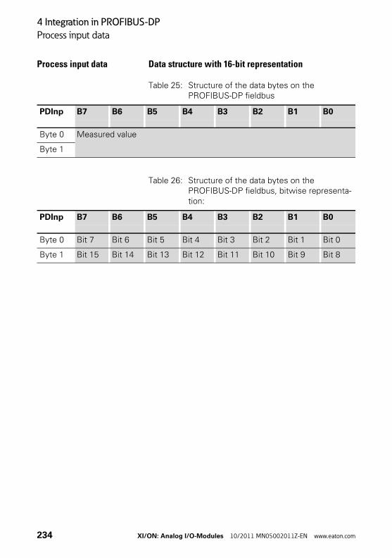
4 Integration in PROFIBUS-DP
Process input data
Process input data Data structure with 16-bit representation
Table 25: Structure of the data bytes on the PROFIBUS-DP fieldbus
Table 26: Structure of the data bytes on the PROFIBUS-DP fieldbus, bitwise representa-tion:
PDInp B7 B6 B5 B4 B3 B2 B1 B0
Byte 0 Measured value
Byte 1
PDInp B7 B6 B5 B4 B3 B2 B1 B0
Byte 0 Bit 7 Bit 6 Bit 5 Bit 4 Bit 3 Bit 2 Bit 1 Bit 0
Byte 1 Bit 15 Bit 14 Bit 13 Bit 12 Bit 11 Bit 10 Bit 9 Bit 8
234 XI/ON: Analog I/O-Modules 10/2011 MN05002011Z-EN www.eaton.com
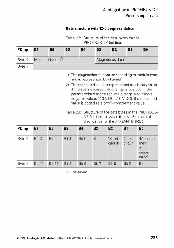
4 Integration in PROFIBUS-DP
Process input data
Data structure with 12-bit representation
Table 27: Structure of the data bytes on the PROFIBUS-DP fieldbus
1) The diagnostics data varies according to module type and is represented by channel
2) The measured value is represented as a binary value if the set measured value range is positive. If the parameterised measured value range also allows negative values (-10 V DC…10 V DC), the measured value is coded as a two's complement value.
Table 28: Structure of the data bytes in the PROFIBUS-DP fieldbus, bitwise display - Example of diagnostics for the XN-2AI-PT/NI-2/3
X = reserved
PDInp B7 B6 B5 B4 B3 B2 B1 B0
Byte 0 Measured value2) Diagnostics data1)
Byte 1
PDInp B7 B6 B5 B4 B3 B2 B1 B0
Byte 0 Bit 3 Bit 2 Bit 1 Bit 0 X "Short-circuit"
Open circuit
"Measure-ment value range error"
Byte 1 Bit 11 Bit 10 Bit 9 Bit 8 Bit 7 Bit 6 Bit 5 Bit 4
XI/ON: Analog I/O-Modules 10/2011 MN05002011Z-EN www.eaton.com 235
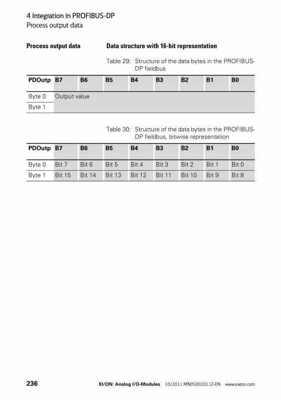
4 Integration in PROFIBUS-DP
Process output data
Process output data Data structure with 16-bit representation
Table 29: Structure of the data bytes in the PROFIBUS-DP fieldbus
Table 30: Structure of the data bytes in the PROFIBUS-DP fieldbus, bitwise representation
PDOutp B7 B6 B5 B4 B3 B2 B1 B0
Byte 0 Output value
Byte 1
PDOutp B7 B6 B5 B4 B3 B2 B1 B0
Byte 0 Bit 7 Bit 6 Bit 5 Bit 4 Bit 3 Bit 2 Bit 1 Bit 0
Byte 1 Bit 15 Bit 14 Bit 13 Bit 12 Bit 11 Bit 10 Bit 9 Bit 8
236 XI/ON: Analog I/O-Modules 10/2011 MN05002011Z-EN www.eaton.com
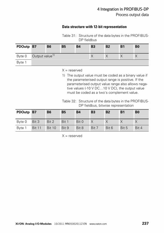
4 Integration in PROFIBUS-DP
Process output data
Data structure with 12-bit representation
Table 31: Structure of the data bytes in the PROFIBUS-DP fieldbus
X = reserved
1) The output value must be coded as a binary value if the parameterised output range is positive. If the parameterised output value range also allows nega-tive values (-10 V DC…10 V DC), the output value must be coded as a two's complement value.
Table 32: Structure of the data bytes in the PROFIBUS-DP fieldbus, bitwise representation
X = reserved
PDOutp B7 B6 B5 B4 B3 B2 B1 B0
Byte 0 Output value1) X X X X
Byte 1
PDOutp B7 B6 B5 B4 B3 B2 B1 B0
Byte 0 Bit 3 Bit 2 Bit 1 Bit 0 X X X X
Byte 1 Bit 11 Bit 10 Bit 9 Bit 8 Bit 7 Bit 6 Bit 5 Bit 4
XI/ON: Analog I/O-Modules 10/2011 MN05002011Z-EN www.eaton.com 237
4 Integration in PROFIBUS-DP
Parameter data structure
Parameter data structure The structure of the parameter data of the analog I/O module depends on the module type. The structure of the parameter data for each module type is shown further on in this section.
It must be remembered that all the modules that appear in the Standard module representation(e.g. "S-XN-2AO-U(-10/0..+10VDC)") will occupy one parameter byte when project engineering with a software tool.
This parameter byte contains the number of all other parameter bytes of the module.
The response of the analog outputs in the event of an error (change of module, wrong module replaced, fieldbus error) can be defined through gateway parameters.
The description of these gateway parameters can be found in the manual:
• User Manual XI/ON:Gateways for PROFIBUS-DP
238 XI/ON: Analog I/O-Modules 10/2011 MN05002011Z-EN www.eaton.com
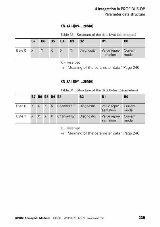
4 Integration in PROFIBUS-DP
Parameter data structure
XN-1AI-I(0/4…20MA)
Table 33: Structure of the data byte (parameters)
X = reserved
→ “Meaning of the parameter data” Page 246
XN-2AI-I(0/4…20MA)
Table 34: Structure of the data bytes (parameters)
X = reserved
→ “Meaning of the parameter data” Page 246
B7 B6 B5 B4 B3 B2 B1 B0
Byte 0 X X X X X Diagnostic Value repre-sentation
Current mode
B7 B6 B5 B4 B3 B2 B1 B0
Byte 0 X X X X Channel K1 Diagnostic Value repre-sentation
Current mode
Byte 1 X X X X Channel K2 Diagnostic Value repre-sentation
Current mode
XI/ON: Analog I/O-Modules 10/2011 MN05002011Z-EN www.eaton.com 239
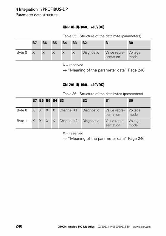
4 Integration in PROFIBUS-DP
Parameter data structure
XN-1AI-U(-10/0…+10VDC)
Table 35: Structure of the data byte (parameters)
X = reserved
→ “Meaning of the parameter data” Page 246
XN-2AI-U(-10/0…+10VDC)
Table 36: Structure of the data bytes (parameters)
X = reserved
→ “Meaning of the parameter data” Page 246
B7 B6 B5 B4 B3 B2 B1 B0
Byte 0 X X X X X Diagnostic Value repre-sentation
Voltage mode
B7 B6 B5 B4 B3 B2 B1 B0
Byte 0 X X X X Channel K1 Diagnostic Value repre-sentation
Voltage mode
Byte 1 X X X X Channel K2 Diagnostic Value repre-sentation
Voltage mode
240 XI/ON: Analog I/O-Modules 10/2011 MN05002011Z-EN www.eaton.com
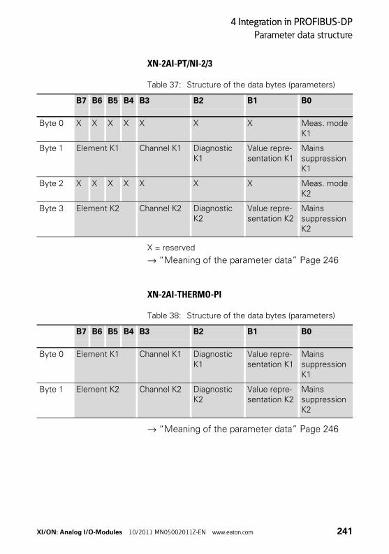
4 Integration in PROFIBUS-DP
Parameter data structure
XN-2AI-PT/NI-2/3
Table 37: Structure of the data bytes (parameters)
X = reserved
→ “Meaning of the parameter data” Page 246
XN-2AI-THERMO-PI
Table 38: Structure of the data bytes (parameters)
→ “Meaning of the parameter data” Page 246
B7 B6 B5 B4 B3 B2 B1 B0
Byte 0 X X X X X X X Meas. mode K1
Byte 1 Element K1 Channel K1 Diagnostic K1
Value repre-sentation K1
Mains suppression K1
Byte 2 X X X X X X X Meas. mode K2
Byte 3 Element K2 Channel K2 Diagnostic K2
Value repre-sentation K2
Mains suppression K2
B7 B6 B5 B4 B3 B2 B1 B0
Byte 0 Element K1 Channel K1 Diagnostic K1
Value repre-sentation K1
Mains suppression K1
Byte 1 Element K2 Channel K2 Diagnostic K2
Value repre-sentation K2
Mains suppression K2
XI/ON: Analog I/O-Modules 10/2011 MN05002011Z-EN www.eaton.com 241
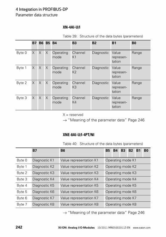
4 Integration in PROFIBUS-DP
Parameter data structure
XN-4AI-U/I
Table 39: Structure of the data bytes (parameters)
X = reserved
→ “Meaning of the parameter data” Page 246
XNE-8AI-U/I-4PT/NI
Table 40: Structure of the data bytes (parameters)
→ “Meaning of the parameter data” Page 246
B7 B6 B5 B4 B3 B2 B1 B0
Byte 0 X X X Operating mode
Channel K1
Diagnostic Value represen-tation
Range
Byte 1 X X X Operating mode
Channel K2
Diagnostic Value represen-tation
Range
Byte 2 X X X Operating mode
Channel K3
Diagnostic Value represen-tation
Range
Byte 3 X X X Operating mode
Channel K4
Diagnostic Value represen-tation
Range
B7 B6 B5 B4 B3 B2 B1 B0
Byte 0 Diagnostic K1 Value representation K1 Operating mode K1
Byte 1 Diagnostic K2 Value representation K2 Operating mode K2
Byte 2 Diagnostic K3 Value representation K3 Operating mode K3
Byte 3 Diagnostic K4 Value representation K4 Operating mode K4
Byte 4 Diagnostic K5 Value representation K5 Operating mode K5
Byte 5 Diagnostic K6 Value representation K6 Operating mode K6
Byte 6 Diagnostic K7 Value representation K7 Operating mode K7
Byte 7 Diagnostic K8 Value representation K8 Operating mode K8
242 XI/ON: Analog I/O-Modules 10/2011 MN05002011Z-EN www.eaton.com
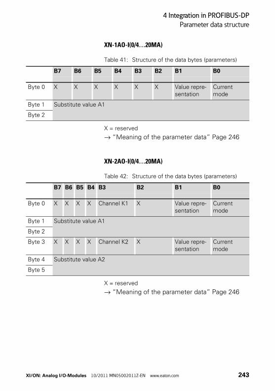
4 Integration in PROFIBUS-DP
Parameter data structure
XN-1AO-I(0/4…20MA)
Table 41: Structure of the data bytes (parameters)
X = reserved
→ “Meaning of the parameter data” Page 246
XN-2AO-I(0/4…20MA)
Table 42: Structure of the data bytes (parameters)
X = reserved
→ “Meaning of the parameter data” Page 246
B7 B6 B5 B4 B3 B2 B1 B0
Byte 0 X X X X X X Value repre-sentation
Current mode
Byte 1 Substitute value A1
Byte 2
B7 B6 B5 B4 B3 B2 B1 B0
Byte 0 X X X X Channel K1 X Value repre-sentation
Current mode
Byte 1 Substitute value A1
Byte 2
Byte 3 X X X X Channel K2 X Value repre-sentation
Current mode
Byte 4 Substitute value A2
Byte 5
XI/ON: Analog I/O-Modules 10/2011 MN05002011Z-EN www.eaton.com 243
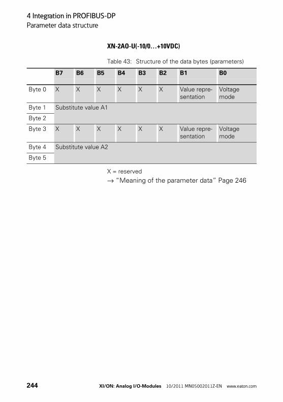
4 Integration in PROFIBUS-DP
Parameter data structure
XN-2AO-U(-10/0…+10VDC)
Table 43: Structure of the data bytes (parameters)
X = reserved
→ “Meaning of the parameter data” Page 246
B7 B6 B5 B4 B3 B2 B1 B0
Byte 0 X X X X X X Value repre-sentation
Voltage mode
Byte 1 Substitute value A1
Byte 2
Byte 3 X X X X X X Value repre-sentation
Voltage mode
Byte 4 Substitute value A2
Byte 5
244 XI/ON: Analog I/O-Modules 10/2011 MN05002011Z-EN www.eaton.com
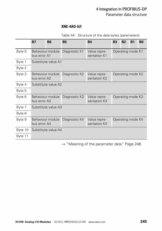
4 Integration in PROFIBUS-DP
Parameter data structure
XNE-4AO-U/I
Table 44: Structure of the data bytes (parameters)
→ “Meaning of the parameter data” Page 246
B7 B6 B5 B4 B3 B2 B1 B0
Byte 0 Behaviour module bus error A1
Diagnostic K1 Value repre-sentation K1
Operating mode K1
Byte 1 Substitute value A1
Byte 2
Byte 3 Behaviour module bus error A2
Diagnostic K2 Value repre-sentation K2
Operating mode K2
Byte 4 Substitute value A2
Byte 5
Byte 6 Behaviour module bus error A3
Diagnostic K3 Value repre-sentation K3
Operating mode K3
Byte 7 Substitute value A3
Byte 8
Byte 9 Behaviour module bus error A4
Diagnostic K4 Value repre-sentation K4
Operating mode K4
Byte 10 Substitute value A4
Byte 11
XI/ON: Analog I/O-Modules 10/2011 MN05002011Z-EN www.eaton.com 245
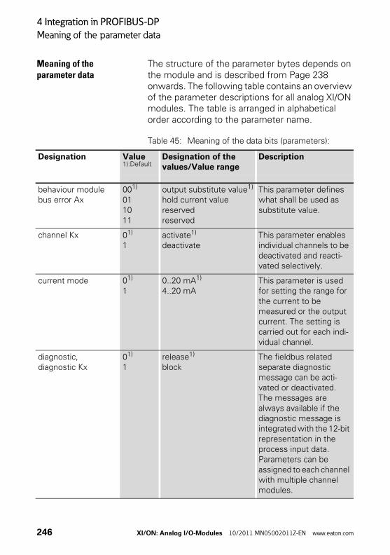
4 Integration in PROFIBUS-DP
Meaning of the parameter data
Meaning of the parameter data
The structure of the parameter bytes depends on the module and is described from Page 238 onwards. The following table contains an overview of the parameter descriptions for all analog XI/ON modules. The table is arranged in alphabetical order according to the parameter name.
Table 45: Meaning of the data bits (parameters):
Designation Value1):Default
Designation of the values/Value range
Description
behaviour module bus error Ax
001)
011011
output substitute value1)
hold current valuereservedreserved
This parameter defines what shall be used as substitute value.
channel Kx 01)
1activate1)
deactivateThis parameter enables individual channels to be deactivated and reacti-vated selectively.
current mode 01)
10..20 mA1)
4..20 mAThis parameter is used for setting the range for the current to be measured or the output current. The setting is carried out for each indi-vidual channel.
diagnostic, diagnostic Kx
01)
1release1)
blockThe fieldbus related separate diagnostic message can be acti-vated or deactivated.The messages are always available if the diagnostic message is integrated with the 12-bit representation in the process input data.Parameters can be assigned to each channel with multiple channel modules.
246 XI/ON: Analog I/O-Modules 10/2011 MN05002011Z-EN www.eaton.com
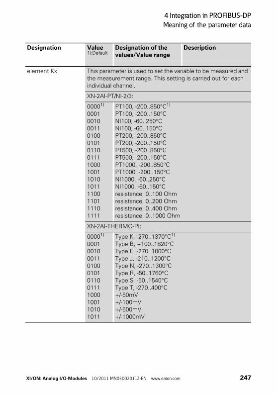
4 Integration in PROFIBUS-DP
Meaning of the parameter data
element Kx This parameter is used to set the variable to be measured and the measurement range. This setting is carried out for each individual channel.
XN-2AI-PT/NI-2/3:
00001) 000100100011010001010110011110001001101010111100110111101111
PT100, -200..850°C1)
PT100, -200..150°CNI100, -60..250°CNI100, -60..150°CPT200, -200..850°CPT200, -200..150°CPT500, -200..850°CPT500, -200..150°CPT1000, -200..850°CPT1000, -200..150°CNI1000, -60..250°CNI1000, -60..150°Cresistance, 0..100 Ohmresistance, 0..200 Ohmresistance, 0..400 Ohmresistance, 0..1000 Ohm
XN-2AI-THERMO-PI:
00001) 00010010001101000101011001111000100110101011
Type K, -270..1370°C1)
Type B, +100..1820°CType E, -270..1000°CType J, -210..1200°CType N, -270..1300°CType R, -50..1760°CType S, -50..1540°CType T, -270..400°C+/-50mV+/-100mV+/-500mV+/-1000mV
Designation Value1):Default
Designation of the values/Value range
Description
XI/ON: Analog I/O-Modules 10/2011 MN05002011Z-EN www.eaton.com 247
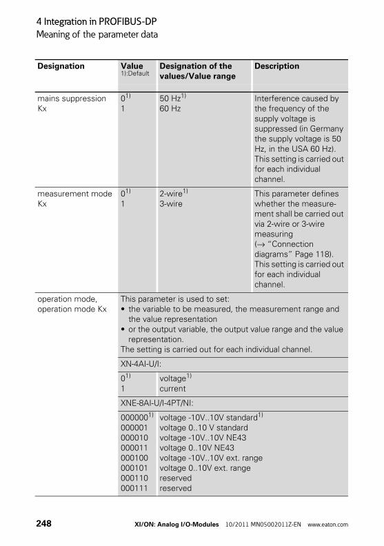
4 Integration in PROFIBUS-DP
Meaning of the parameter data
mains suppression Kx
01)
150 Hz1)
60 HzInterference caused by the frequency of the supply voltage is suppressed (in Germany the supply voltage is 50 Hz, in the USA 60 Hz).This setting is carried out for each individual channel.
measurement mode Kx
01)
12-wire1)
3-wireThis parameter defines whether the measure-ment shall be carried out via 2-wire or 3-wire measuring (→ “Connection diagrams” Page 118). This setting is carried out for each individual channel.
operation mode, operation mode Kx
This parameter is used to set:• the variable to be measured, the measurement range and
the value representation• or the output variable, the output value range and the value
representation.The setting is carried out for each individual channel.
XN-4AI-U/I:
01)
1voltage1)
current
XNE-8AI-U/I-4PT/NI:
0000001)
000001000010000011000100000101000110000111
voltage -10V..10V standard1)
voltage 0..10 V standardvoltage -10V..10V NE43voltage 0..10V NE43voltage -10V..10V ext. rangevoltage 0..10V ext. rangereservedreserved
Designation Value1):Default
Designation of the values/Value range
Description
248 XI/ON: Analog I/O-Modules 10/2011 MN05002011Z-EN www.eaton.com
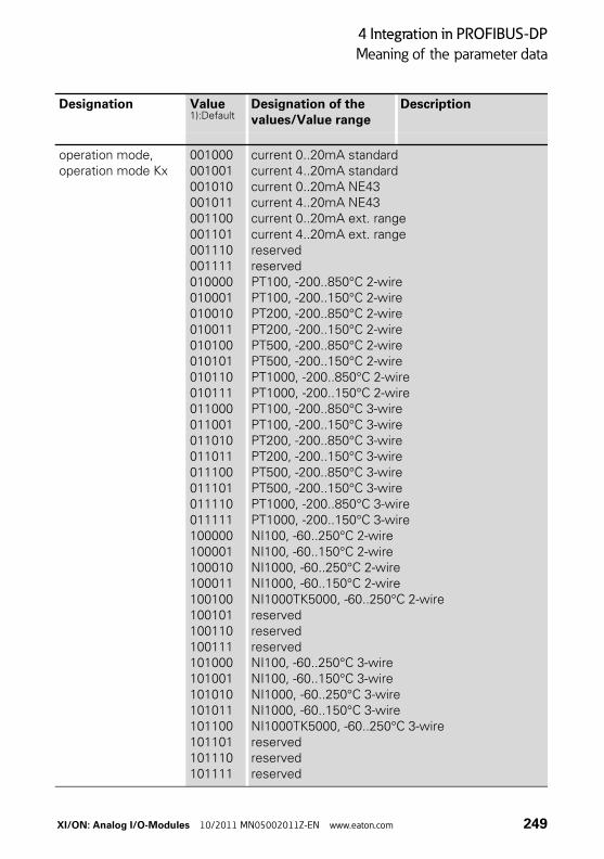
4 Integration in PROFIBUS-DP
Meaning of the parameter data
operation mode, operation mode Kx
001000001001001010001011001100001101001110001111010000010001010010010011010100010101010110010111011000011001011010011011011100011101011110011111100000100001100010100011100100100101100110100111101000101001101010101011101100101101101110101111
current 0..20mA standardcurrent 4..20mA standardcurrent 0..20mA NE43current 4..20mA NE43current 0..20mA ext. rangecurrent 4..20mA ext. rangereservedreservedPT100, -200..850°C 2-wirePT100, -200..150°C 2-wirePT200, -200..850°C 2-wirePT200, -200..150°C 2-wirePT500, -200..850°C 2-wirePT500, -200..150°C 2-wirePT1000, -200..850°C 2-wirePT1000, -200..150°C 2-wirePT100, -200..850°C 3-wirePT100, -200..150°C 3-wirePT200, -200..850°C 3-wirePT200, -200..150°C 3-wirePT500, -200..850°C 3-wirePT500, -200..150°C 3-wirePT1000, -200..850°C 3-wirePT1000, -200..150°C 3-wireNI100, -60..250°C 2-wireNI100, -60..150°C 2-wireNI1000, -60..250°C 2-wireNI1000, -60..150°C 2-wireNI1000TK5000, -60..250°C 2-wirereservedreservedreservedNI100, -60..250°C 3-wireNI100, -60..150°C 3-wireNI1000, -60..250°C 3-wireNI1000, -60..150°C 3-wireNI1000TK5000, -60..250°C 3-wirereservedreservedreserved
Designation Value1):Default
Designation of the values/Value range
Description
XI/ON: Analog I/O-Modules 10/2011 MN05002011Z-EN www.eaton.com 249
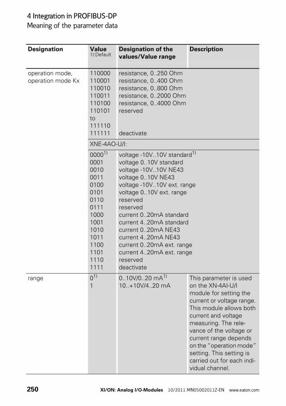
4 Integration in PROFIBUS-DP
Meaning of the parameter data
operation mode, operation mode Kx
110000110001110010110011110100110101 to 111110111111
resistance, 0..250 Ohmresistance, 0..400 Ohmresistance, 0..800 Ohmresistance, 0..2000 Ohmresistance, 0..4000 Ohmreserved
deactivate
XNE-4AO-U/I:
00001)
000100100011010001010110011110001001101010111100110111101111
voltage -10V..10V standard1)
voltage 0..10V standardvoltage -10V..10V NE43voltage 0..10V NE43voltage -10V..10V ext. rangevoltage 0..10V ext. rangereservedreservedcurrent 0..20mA standardcurrent 4..20mA standardcurrent 0..20mA NE43current 4..20mA NE43current 0..20mA ext. rangecurrent 4..20mA ext. rangereserveddeactivate
range 01)
10..10V/0..20 mA1) 10..+10V/4..20 mA
This parameter is used on the XN-4AI-U/I module for setting the current or voltage range. This module allows both current and voltage measuring. The rele-vance of the voltage or current range depends on the “operation mode” setting. This setting is carried out for each indi-vidual channel.
Designation Value1):Default
Designation of the values/Value range
Description
250 XI/ON: Analog I/O-Modules 10/2011 MN05002011Z-EN www.eaton.com
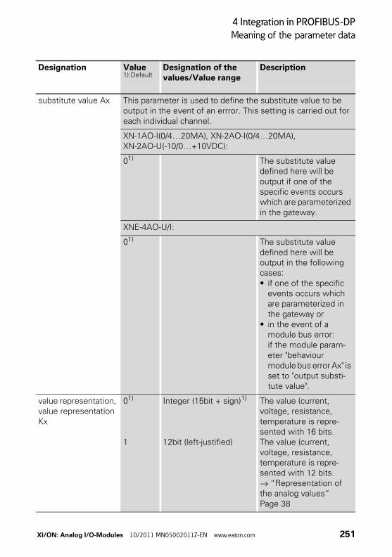
4 Integration in PROFIBUS-DP
Meaning of the parameter data
substitute value Ax This parameter is used to define the substitute value to be output in the event of an errror. This setting is carried out for each individual channel.
XN-1AO-I(0/4…20MA), XN-2AO-I(0/4…20MA), XN-2AO-U(-10/0…+10VDC):
01) The substitute value defined here will be output if one of the specific events occurs which are parameterized in the gateway.
XNE-4AO-U/I:
01) The substitute value defined here will be output in the following cases:• if one of the specific
events occurs which are parameterized in the gateway or
• in the event of a module bus error: if the module param-eter "behaviour module bus error Ax" is set to "output substi-tute value".
value representation, value representation Kx
01)
1
Integer (15bit + sign)1)
12bit (left-justified)
The value (current, voltage, resistance, temperature is repre-sented with 16 bits.The value (current, voltage, resistance, temperature is repre-sented with 12 bits.→ “Representation of the analog values” Page 38
Designation Value1):Default
Designation of the values/Value range
Description
XI/ON: Analog I/O-Modules 10/2011 MN05002011Z-EN www.eaton.com 251
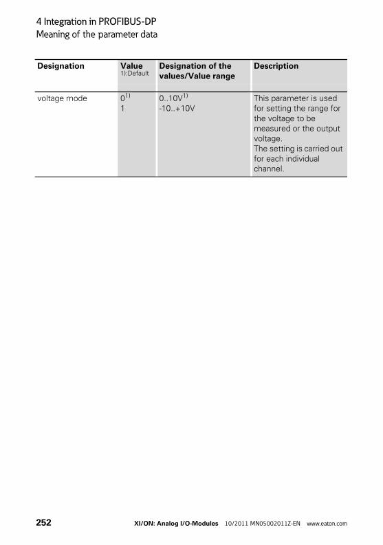
4 Integration in PROFIBUS-DP
Meaning of the parameter data
voltage mode 01)
10..10V1)
-10..+10VThis parameter is used for setting the range for the voltage to be measured or the output voltage. The setting is carried out for each individual channel.
Designation Value1):Default
Designation of the values/Value range
Description
252 XI/ON: Analog I/O-Modules 10/2011 MN05002011Z-EN www.eaton.com
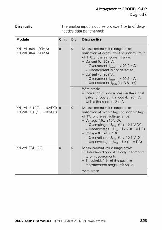
4 Integration in PROFIBUS-DP
Diagnostic
Diagnostic The analog input modules provide 1 byte of diag-nostics data per channel:
Module Chn. Bit Diagnostics
XN-1AI-I(0/4…20MA)XN-2AI-I(0/4…20MA)
n 0 Measurement value range error:Indication of overcurrent or undercurrent of 1 % of the set current range.• Current 0…20 mA:
– Overcurrent: Imax (I > 20.2 mA);– Undercurrent is not detected.
• Current 4…20 mA:– Overcurrent: Imax (I > 20.2 mA);– Undercurrent: Imin (I < 3.8 mA)
1 Wire break:• Indication of a wire break in the signal
cable for operating mode 4…20 mA with a threshold of 3 mA.
XN-1AI-U(-10/0…+10VDC)XN-2AI-U(-10/0…+10VDC)
n 0 Measurement value range error:Indication of overvoltage or undervoltage of 1% of the set voltage range.• Voltage -10…+10 V DC:
– Overvoltage: Umax (U > 10.1 V DC)– Undervoltage: Umin (U < -10.1 V DC)
• Voltage 0…+10 V DC:– Overvoltage: Umax (U > 10.1 V DC)– Undervoltage: Umin (U < 0.1 V DC)
XN-2AI-PT/NI-2/3 n 0 Measurement value range error:• Unterflow diagnostics only in tempera-
ture measurements• Threshold: 1 % of the positive
measurement range limit value
1 Wire break
XI/ON: Analog I/O-Modules 10/2011 MN05002011Z-EN www.eaton.com 253
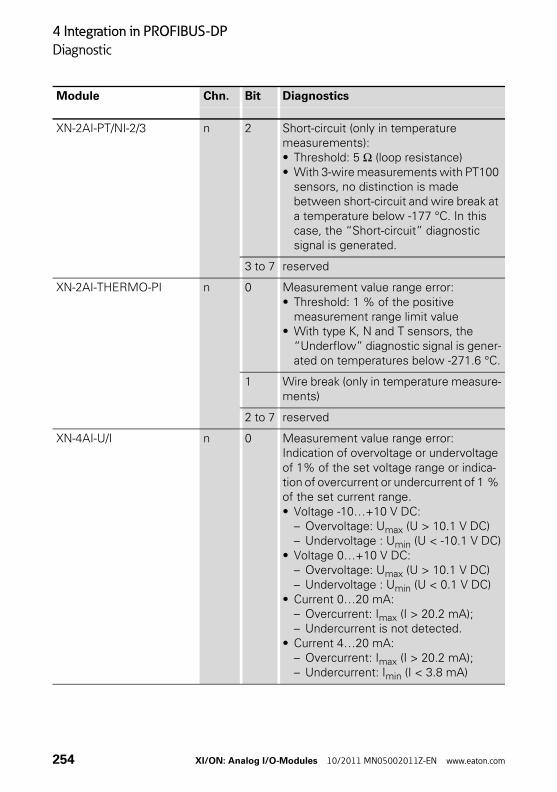
4 Integration in PROFIBUS-DP
Diagnostic
XN-2AI-PT/NI-2/3 n 2 Short-circuit (only in temperature measurements):• Threshold: 5 Ω (loop resistance)• With 3-wire measurements with PT100
sensors, no distinction is made between short-circuit and wire break at a temperature below -177 °C. In this case, the “Short-circuit” diagnostic signal is generated.
3 to 7 reserved
XN-2AI-THERMO-PI n 0 Measurement value range error:• Threshold: 1 % of the positive
measurement range limit value• With type K, N and T sensors, the
“Underflow” diagnostic signal is gener-ated on temperatures below -271.6 °C.
1 Wire break (only in temperature measure-ments)
2 to 7 reserved
XN-4AI-U/I n 0 Measurement value range error:Indication of overvoltage or undervoltage of 1% of the set voltage range or indica-tion of overcurrent or undercurrent of 1 % of the set current range.• Voltage -10…+10 V DC:
– Overvoltage: Umax (U > 10.1 V DC)– Undervoltage : Umin (U < -10.1 V DC)
• Voltage 0…+10 V DC:– Overvoltage: Umax (U > 10.1 V DC)– Undervoltage : Umin (U < 0.1 V DC)
• Current 0…20 mA:– Overcurrent: Imax (I > 20.2 mA);– Undercurrent is not detected.
• Current 4…20 mA:– Overcurrent: Imax (I > 20.2 mA);– Undercurrent: Imin (I < 3.8 mA)
Module Chn. Bit Diagnostics
254 XI/ON: Analog I/O-Modules 10/2011 MN05002011Z-EN www.eaton.com
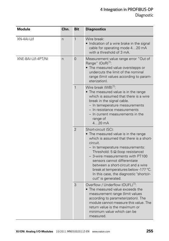
4 Integration in PROFIBUS-DP
Diagnostic
XN-4AI-U/I n 1 Wire break:• Indication of a wire brake in the signal
cable for operating mode 4…20 mA with a threshold of 3 mA.
XNE-8AI-U/I-4PT/NI n 0 Measurement value range error “Out of Range” (OoR)1):• The measured value overstepps or
undercuts the limit of the nominal range (limit values according to param-eterization).
1 Wire break (WB)1):• The measured value is in the range
which is assumed that there is a wire break in the signal cable.– In temeperature messurements– In resistance measurements– In current measurements in the
range of 4…20 mA
2 Short-circuit (SC):• The measured value is in the range
which is assumed that there is a short-circuit.– In temeperature messurements:
Threshold: 5 Ω (loop resistance)– 3-wire measurements with PT100
sensors cannot differentiate between a short-circuit and a wire break at temperatures below -177 °C. In this case, the diagnostic "shortcir-cuit" is generated.
3 Overflow / Underflow (OUFL)1):• The measured value exceeds the
measurement range (limit values according to parameterization). The module cannot measure this value. The return value is the maximum or minimum value which can be measured.
Module Chn. Bit Diagnostics
XI/ON: Analog I/O-Modules 10/2011 MN05002011Z-EN www.eaton.com 255
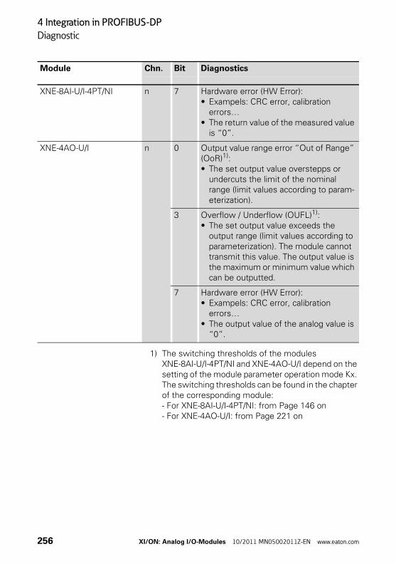
4 Integration in PROFIBUS-DP
Diagnostic
1) The switching thresholds of the modules XNE-8AI-U/I-4PT/NI and XNE-4AO-U/I depend on the setting of the module parameter operation mode Kx. The switching thresholds can be found in the chapter of the corresponding module:- For XNE-8AI-U/I-4PT/NI: from Page 146 on- For XNE-4AO-U/I: from Page 221 on
XNE-8AI-U/I-4PT/NI n 7 Hardware error (HW Error):• Exampels: CRC error, calibration
errors…• The return value of the measured value
is “0”.
XNE-4AO-U/I n 0 Output value range error “Out of Range” (OoR)1):• The set output value overstepps or
undercuts the limit of the nominal range (limit values according to param-eterization).
3 Overflow / Underflow (OUFL)1):• The set output value exceeds the
output range (limit values according to parameterization). The module cannot transmit this value. The output value is the maximum or minimum value which can be outputted.
7 Hardware error (HW Error):• Exampels: CRC error, calibration
errors…• The output value of the analog value is
“0”.
Module Chn. Bit Diagnostics
256 XI/ON: Analog I/O-Modules 10/2011 MN05002011Z-EN www.eaton.com
5 Integration in CANopen
Process input data / process output data
5 Integration in CANopen
Process input data / process output data
The analog module types have 2 bytes of process data for each channel. These bytes contain the measured value of the channel (analog input) or the voltage or current value of the channel (analog output).
The analog input modules only provide process input data.
The analog output modules only receive process output data.
The process input and process output data is represented using the objects defined by the Device Profile for I/O Devices CiA DS-401.
→ You can find the latest EDS files on our home page (www.eaton-automation.com),under „DOWNLOADS“.
XI/ON: Analog I/O-Modules 10/2011 MN05002011Z-EN www.eaton.com 257
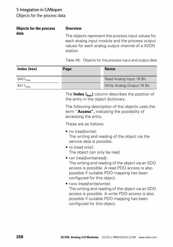
5 Integration in CANopen
Objects for the process data
Objects for the process data
Overview
The objects represent the process input values for each analog input module and the process output values for each analog output channel of a XI/ON station.
Table 46: Objects for the process input and output data
The Index (hex) column describes the position of the entry in the object dictionary.
The following description of the objects uses the term “Access”, indicating the possibility of accessing the entry.
These are as follows:
• rw (read/write):The writing and reading of the object via the service data is possible.
• ro (read only):The object can only be read.
• rwr (read/write/read):The writing and reading of the object via an SDO access is possible. A read PDO access is also possible if suitable PDO mapping has been configured for this object.
• rww (read/write/write):The writing and reading of the object via an SDO access is possible. A write PDO access is also possible if suitable PDO mapping has been configured for this object.
Index (hex) Page Name
6401hex Read Analog Input 16 Bit
6411hex Write Analog Output 16 Bit
258 XI/ON: Analog I/O-Modules 10/2011 MN05002011Z-EN www.eaton.com
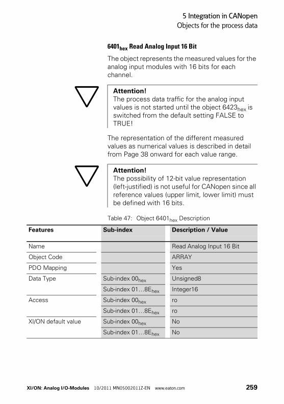
5 Integration in CANopen
Objects for the process data
6401hex Read Analog Input 16 Bit
The object represents the measured values for the analog input modules with 16 bits for each channel.
The representation of the different measured values as numerical values is described in detail from Page 38 onward for each value range.
Table 47: Object 6401hex Description
Attention!The process data traffic for the analog input values is not started until the object 6423hex is switched from the default setting FALSE to TRUE!
Attention!The possibility of 12-bit value representation (left-justified) is not useful for CANopen since all reference values (upper limit, lower limit) must be defined with 16 bits.
Features Sub-index Description / Value
Name Read Analog Input 16 Bit
Object Code ARRAY
PDO Mapping Yes
Data Type Sub-index 00hex Unsigned8
Sub-index 01…8Ehex Integer16
Access Sub-index 00hex ro
Sub-index 01…8Ehex ro
XI/ON default value Sub-index 00hex No
Sub-index 01…8Ehex No
XI/ON: Analog I/O-Modules 10/2011 MN05002011Z-EN www.eaton.com 259
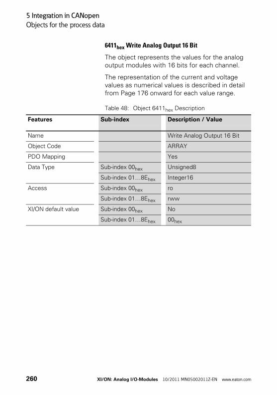
5 Integration in CANopen
Objects for the process data
6411hex Write Analog Output 16 Bit
The object represents the values for the analog output modules with 16 bits for each channel.
The representation of the current and voltage values as numerical values is described in detail from Page 176 onward for each value range.
Table 48: Object 6411hex Description
Features Sub-index Description / Value
Name Write Analog Output 16 Bit
Object Code ARRAY
PDO Mapping Yes
Data Type Sub-index 00hex Unsigned8
Sub-index 01…8Ehex Integer16
Access Sub-index 00hex ro
Sub-index 01…8Ehex rww
XI/ON default value Sub-index 00hex No
Sub-index 01…8Ehex 00hex
260 XI/ON: Analog I/O-Modules 10/2011 MN05002011Z-EN www.eaton.com
5 Integration in CANopen
Objects for Interrupt behaviour
Objects for Interrupt behaviour
Objects 6421…6428hex can be used to control the event-triggered transmission of the process input data. As well as these event-triggered control objects, the transmission frequency of the process input data is also controlled by means of objects 1800hex to 181Fhex. These objects are described in the manual:
• User Manual XI/ON:Gateways for CANopen
→ Remember that the object → “6423hex Analog Input Global Interrupt Enable” Page 265 must be used in order to enable the possibility of trans-mitting the process input data using an interrupt signal!
XI/ON: Analog I/O-Modules 10/2011 MN05002011Z-EN www.eaton.com 261
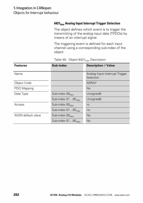
5 Integration in CANopen
Objects for Interrupt behaviour
6421hex Analog Input Interrupt Trigger Selection
The object defines which event is to trigger the transmitting of the analog input data (TPDOs) by means of an interrupt signal.
The triggering event is defined for each input channel using a corresponding sub-index of the object.
Table 49: Object 6421hex Description
Features Sub-index Description / Value
Name Analog Input Interrupt Trigger Selection
Object Code ARRAY
PDO Mapping No
Data Type Sub-index 00hex Unsigned8
Sub-index 01…8Ehex Unsigned8
Access Sub-index 00hex ro
Sub-index 01…8Ehex rw
XI/ON default value Sub-index 00hex No
Sub-index 01…8Ehex No
262 XI/ON: Analog I/O-Modules 10/2011 MN05002011Z-EN www.eaton.com
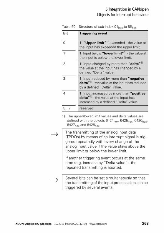
5 Integration in CANopen
Objects for Interrupt behaviour
Table 50: Structure of sub-index 01hex to 8Ehex
1) The upper/lower limit values and delta values are defined with the objects 6424hex, 6425hex, 6426hex, 6427hex and 6428hex.
Bit Triggering event
0 1: “Upper limit”1) exceeded - the value at the input has exceeded the upper limit.
1 1: Input below “lower limit”1) - the value at the input is below the lower limit.
2 1: Input changed by more than “delta”1) - the value at the input has changed by a defined “Delta” value.
3 1: Input reduced by more than “negative delta”1) - the value at the input has reduced by a defined “Delta” value.
4 1: Input increased by more than “positive delta”1) - the value at the input has increased by a defined “Delta” value.
5…7 reserved
→ The transmitting of the analog input data (TPDOs) by means of an interrupt signal is trig-gered repeatedly with every change of the analog input value if the value stays above the upper limit or below the lower limit.
If another triggering event occurs at the same time (e.g. increase by “Delta value”), the repeated transmitting is aborted.
→ Several bits can be set simultaneously so that the transmitting of the input process data can be triggered by several events.
XI/ON: Analog I/O-Modules 10/2011 MN05002011Z-EN www.eaton.com 263
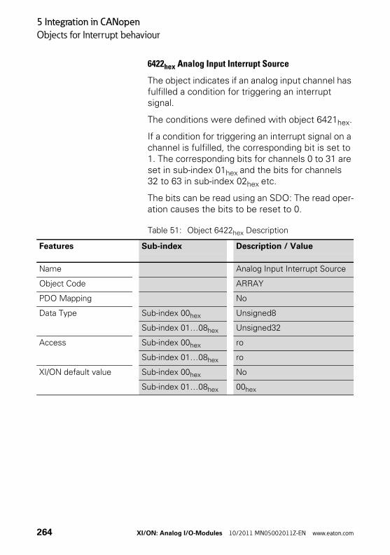
5 Integration in CANopen
Objects for Interrupt behaviour
6422hex Analog Input Interrupt Source
The object indicates if an analog input channel has fulfilled a condition for triggering an interrupt signal.
The conditions were defined with object 6421hex.
If a condition for triggering an interrupt signal on a channel is fulfilled, the corresponding bit is set to 1. The corresponding bits for channels 0 to 31 are set in sub-index 01hex and the bits for channels 32 to 63 in sub-index 02hex etc.
The bits can be read using an SDO: The read oper-ation causes the bits to be reset to 0.
Table 51: Object 6422hex Description
Features Sub-index Description / Value
Name Analog Input Interrupt Source
Object Code ARRAY
PDO Mapping No
Data Type Sub-index 00hex Unsigned8
Sub-index 01…08hex Unsigned32
Access Sub-index 00hex ro
Sub-index 01…08hex ro
XI/ON default value Sub-index 00hex No
Sub-index 01…08hex 00hex
264 XI/ON: Analog I/O-Modules 10/2011 MN05002011Z-EN www.eaton.com
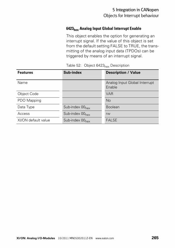
5 Integration in CANopen
Objects for Interrupt behaviour
6423hex Analog Input Global Interrupt Enable
This object enables the option for generating an interrupt signal. If the value of this object is set from the default setting FALSE to TRUE, the trans-mitting of the analog input data (TPDOs) can be triggered by means of an interrupt signal.
Table 52: Object 6423hex Description
Features Sub-index Description / Value
Name Analog Input Global Interrupt Enable
Object Code VAR
PDO Mapping No
Data Type Sub-index 00hex Boolean
Access Sub-index 00hex rw
XI/ON default value Sub-index 00hex FALSE
XI/ON: Analog I/O-Modules 10/2011 MN05002011Z-EN www.eaton.com 265
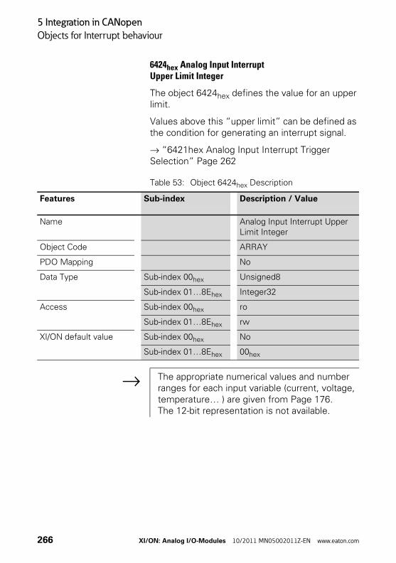
5 Integration in CANopen
Objects for Interrupt behaviour
6424hex Analog Input InterruptUpper Limit Integer
The object 6424hex defines the value for an upper limit.
Values above this “upper limit” can be defined as the condition for generating an interrupt signal.
→ “6421hex Analog Input Interrupt Trigger Selection” Page 262
Table 53: Object 6424hex Description
Features Sub-index Description / Value
Name Analog Input Interrupt Upper Limit Integer
Object Code ARRAY
PDO Mapping No
Data Type Sub-index 00hex Unsigned8
Sub-index 01…8Ehex Integer32
Access Sub-index 00hex ro
Sub-index 01…8Ehex rw
XI/ON default value Sub-index 00hex No
Sub-index 01…8Ehex 00hex
→ The appropriate numerical values and number ranges for each input variable (current, voltage, temperature… ) are given from Page 176.The 12-bit representation is not available.
266 XI/ON: Analog I/O-Modules 10/2011 MN05002011Z-EN www.eaton.com
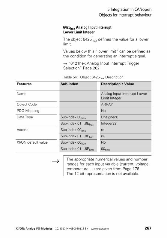
5 Integration in CANopen
Objects for Interrupt behaviour
6425hex Analog Input InterruptLower Limit Integer
The object 6425hex defines the value for a lower limit.
Values below this “lower limit” can be defined as the condition for generating an interrupt signal.
→ “6421hex Analog Input Interrupt Trigger Selection” Page 262
Table 54: Object 6425hex Description
Features Sub-index Description / Value
Name Analog Input Interrupt Lower Limit Integer
Object Code ARRAY
PDO Mapping No
Data Type Sub-index 00hex Unsigned8
Sub-index 01…8Ehex Integer32
Access Sub-index 00hex ro
Sub-index 01…8Ehex rw
XI/ON default value Sub-index 00hex No
Sub-index 01…8Ehex 00hex
→ The appropriate numerical values and number ranges for each input variable (current, voltage, temperature… ) are given from Page 176.The 12-bit representation is not available.
XI/ON: Analog I/O-Modules 10/2011 MN05002011Z-EN www.eaton.com 267
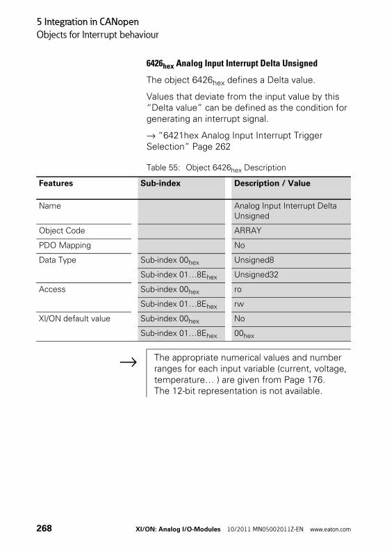
5 Integration in CANopen
Objects for Interrupt behaviour
6426hex Analog Input Interrupt Delta Unsigned
The object 6426hex defines a Delta value.
Values that deviate from the input value by this “Delta value” can be defined as the condition for generating an interrupt signal.
→ “6421hex Analog Input Interrupt Trigger Selection” Page 262
Table 55: Object 6426hex Description
Features Sub-index Description / Value
Name Analog Input Interrupt Delta Unsigned
Object Code ARRAY
PDO Mapping No
Data Type Sub-index 00hex Unsigned8
Sub-index 01…8Ehex Unsigned32
Access Sub-index 00hex ro
Sub-index 01…8Ehex rw
XI/ON default value Sub-index 00hex No
Sub-index 01…8Ehex 00hex
→ The appropriate numerical values and number ranges for each input variable (current, voltage, temperature… ) are given from Page 176.The 12-bit representation is not available.
268 XI/ON: Analog I/O-Modules 10/2011 MN05002011Z-EN www.eaton.com
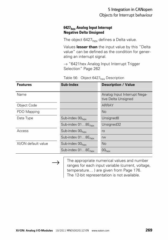
5 Integration in CANopen
Objects for Interrupt behaviour
6427hex Analog Input InterruptNegative Delta Unsigned
The object 6427hex defines a Delta value.
Values lesser than the input value by this “Delta value” can be defined as the condition for gener-ating an interrupt signal.
→ “6421hex Analog Input Interrupt Trigger Selection” Page 262
Table 56: Object 6427hex Description
Features Sub-index Description / Value
Name Analog Input Interrupt Nega-tive Delta Unsigned
Object Code ARRAY
PDO Mapping No
Data Type Sub-index 00hex Unsigned8
Sub-index 01…8Ehex Unsigned32
Access Sub-index 00hex ro
Sub-index 01…8Ehex rw
XI/ON default value Sub-index 00hex No
Sub-index 01…8Ehex 00hex
→ The appropriate numerical values and number ranges for each input variable (current, voltage, temperature… ) are given from Page 176.The 12-bit representation is not available.
XI/ON: Analog I/O-Modules 10/2011 MN05002011Z-EN www.eaton.com 269
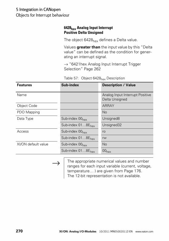
5 Integration in CANopen
Objects for Interrupt behaviour
6428hex Analog Input InterruptPositive Delta Unsigned
The object 6428hex defines a Delta value.
Values greater than the input value by this “Delta value” can be defined as the condition for gener-ating an interrupt signal.
→ “6421hex Analog Input Interrupt Trigger Selection” Page 262
Table 57: Object 6428hex Description
Features Sub-index Description / Value
Name Analog Input Interrupt Positive Delta Unsigned
Object Code ARRAY
PDO Mapping No
Data Type Sub-index 00hex Unsigned8
Sub-index 01…8Ehex Unsigned32
Access Sub-index 00hex ro
Sub-index 01…8Ehex rw
XI/ON default value Sub-index 00hex No
Sub-index 01…8Ehex 00hex
→ The appropriate numerical values and number ranges for each input variable (current, voltage, temperature… ) are given from Page 176.The 12-bit representation is not available.
270 XI/ON: Analog I/O-Modules 10/2011 MN05002011Z-EN www.eaton.com
5 Integration in CANopen
Objects for the substitute output value in the event of an error
Objects for the substitute output value in the eventof an error
Overview
The objects define the substitute value and the substitute-value mode for each individual analog output channel of a XI/ON station. The substitute value is used in the event of a communication error or other unrecoverable error.
These values are not saved by the analog output modules in the integrated memory. If the bus-master or the gateway is replaced, the values will have to be updated.
XI/ON: Analog I/O-Modules 10/2011 MN05002011Z-EN www.eaton.com 271
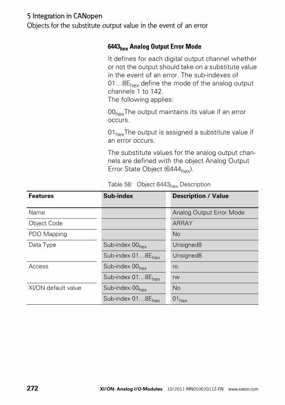
5 Integration in CANopen
Objects for the substitute output value in the event of an error
6443hex Analog Output Error Mode
It defines for each digital output channel whether or not the output should take on a substitute value in the event of an error. The sub-indexes of 01…8Ehex define the mode of the analog output channels 1 to 142. The following applies:
00hexThe output maintains its value if an error occurs.
01hexThe output is assigned a substitute value if an error occurs.
The substitute values for the analog output chan-nels are defined with the object Analog Output Error State Object (6444hex).
Table 58: Object 6443hex Description
Features Sub-index Description / Value
Name Analog Output Error Mode
Object Code ARRAY
PDO Mapping No
Data Type Sub-index 00hex Unsigned8
Sub-index 01…8Ehex Unsigned8
Access Sub-index 00hex ro
Sub-index 01…8Ehex rw
XI/ON default value Sub-index 00hex No
Sub-index 01…8Ehex 01hex
272 XI/ON: Analog I/O-Modules 10/2011 MN05002011Z-EN www.eaton.com
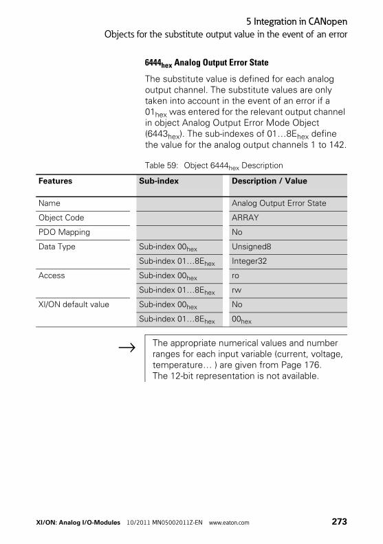
5 Integration in CANopen
Objects for the substitute output value in the event of an error
6444hex Analog Output Error State
The substitute value is defined for each analog output channel. The substitute values are only taken into account in the event of an error if a 01hex was entered for the relevant output channel in object Analog Output Error Mode Object (6443hex). The sub-indexes of 01…8Ehex define the value for the analog output channels 1 to 142.
Table 59: Object 6444hex Description
Features Sub-index Description / Value
Name Analog Output Error State
Object Code ARRAY
PDO Mapping No
Data Type Sub-index 00hex Unsigned8
Sub-index 01…8Ehex Integer32
Access Sub-index 00hex ro
Sub-index 01…8Ehex rw
XI/ON default value Sub-index 00hex No
Sub-index 01…8Ehex 00hex
→ The appropriate numerical values and number ranges for each input variable (current, voltage, temperature… ) are given from Page 176.The 12-bit representation is not available.
XI/ON: Analog I/O-Modules 10/2011 MN05002011Z-EN www.eaton.com 273
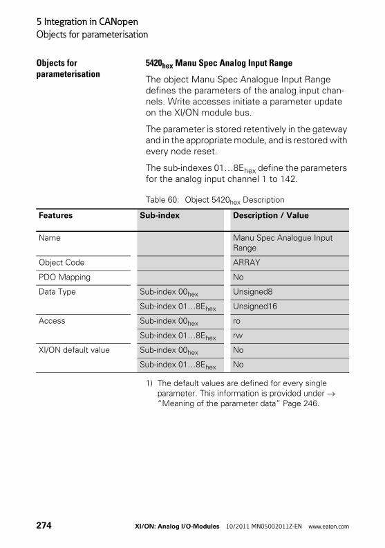
5 Integration in CANopen
Objects for parameterisation
Objects for parameterisation
5420hex Manu Spec Analog Input Range
The object Manu Spec Analogue Input Range defines the parameters of the analog input chan-nels. Write accesses initiate a parameter update on the XI/ON module bus.
The parameter is stored retentively in the gateway and in the appropriate module, and is restored with every node reset.
The sub-indexes 01…8Ehex define the parameters for the analog input channel 1 to 142.
Table 60: Object 5420hex Description
1) The default values are defined for every single parameter. This information is provided under → “Meaning of the parameter data” Page 246.
Features Sub-index Description / Value
Name Manu Spec Analogue Input Range
Object Code ARRAY
PDO Mapping No
Data Type Sub-index 00hex Unsigned8
Sub-index 01…8Ehex Unsigned16
Access Sub-index 00hex ro
Sub-index 01…8Ehex rw
XI/ON default value Sub-index 00hex No
Sub-index 01…8Ehex No
274 XI/ON: Analog I/O-Modules 10/2011 MN05002011Z-EN www.eaton.com
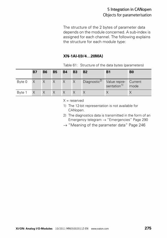
5 Integration in CANopen
Objects for parameterisation
The structure of the 2 bytes of parameter data depends on the module concerned. A sub-index is assigned for each channel. The following explains the structure for each module type:
XN-1AI-I(0/4…20MA)
Table 61: Structure of the data bytes (parameters)
X = reserved
1) The 12-bit representation is not available for CANopen.
2) The diagnostics data is transmitted in the form of an Emergency telegram → “Emergencies” Page 290
→ “Meaning of the parameter data” Page 246
B7 B6 B5 B4 B3 B2 B1 B0
Byte 0 X X X X X Diagnostic2) Value repre-sentation1)
Current mode
Byte 1 X X X X X X X X
XI/ON: Analog I/O-Modules 10/2011 MN05002011Z-EN www.eaton.com 275
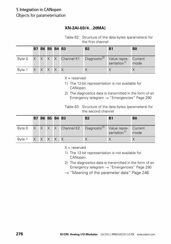
5 Integration in CANopen
Objects for parameterisation
XN-2AI-I(0/4…20MA)
Table 62: Structure of the data bytes (parameters) for the first channel
X = reserved
1) The 12-bit representation is not available for CANopen.
2) The diagnostics data is transmitted in the form of an Emergency telegram → “Emergencies” Page 290
Table 63: Structure of the data bytes (parameters) for the second channel
X = reserved
1) The 12-bit representation is not available for CANopen.
2) The diagnostics data is transmitted in the form of an Emergency telegram → “Emergencies” Page 290
→ “Meaning of the parameter data” Page 246
B7 B6 B5 B4 B3 B2 B1 B0
Byte 0 X X X X Channel K1 Diagnostic2) Value repre-sentation1)
Current mode
Byte 1 X X X X X X X X
B7 B6 B5 B4 B3 B2 B1 B0
Byte 0 X X X X Channel K2 Diagnostic2) Value repre-sentation1)
Current mode
Byte 1 X X X X X X X X
276 XI/ON: Analog I/O-Modules 10/2011 MN05002011Z-EN www.eaton.com
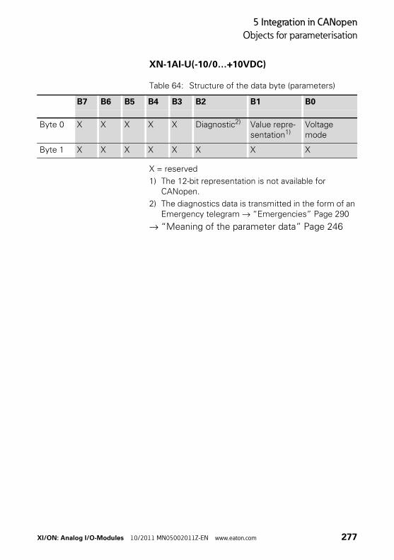
5 Integration in CANopen
Objects for parameterisation
XN-1AI-U(-10/0…+10VDC)
Table 64: Structure of the data byte (parameters)
X = reserved
1) The 12-bit representation is not available for CANopen.
2) The diagnostics data is transmitted in the form of an Emergency telegram → “Emergencies” Page 290
→ “Meaning of the parameter data” Page 246
B7 B6 B5 B4 B3 B2 B1 B0
Byte 0 X X X X X Diagnostic2) Value repre-sentation1)
Voltage mode
Byte 1 X X X X X X X X
XI/ON: Analog I/O-Modules 10/2011 MN05002011Z-EN www.eaton.com 277
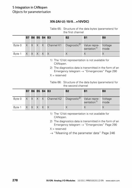
5 Integration in CANopen
Objects for parameterisation
XN-2AI-U(-10/0…+10VDC)
Table 65: Structure of the data bytes (parameters) for the first channel
1) The 12-bit representation is not available for CANopen.
2) The diagnostics data is transmitted in the form of an Emergency telegram → “Emergencies” Page 290
X = reserved
Table 66: Structure of the data bytes (parameters) for the second channel
1) The 12-bit representation is not available for CANopen.
2) The diagnostics data is transmitted in the form of an Emergency telegram → “Emergencies” Page 290
X = reserved
→ “Meaning of the parameter data” Page 246
B7 B6 B5 B4 B3 B2 B1 B0
Byte 0 X X X X Channel K1 Diagnostic2) Value repre-sentation1)
Voltage mode
Byte 1 X X X X X X X X
B7 B6 B5 B4 B3 B2 B1 B0
Byte 0 X X X X Channel K2 Diagnostic2) Value repre-sentation1)
Voltage mode
Byte 1 X X X X X X X X
278 XI/ON: Analog I/O-Modules 10/2011 MN05002011Z-EN www.eaton.com
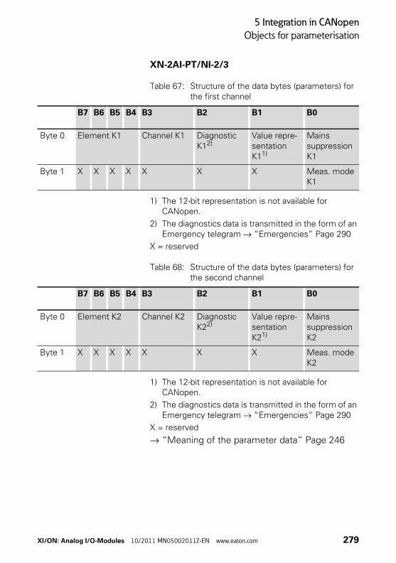
5 Integration in CANopen
Objects for parameterisation
XN-2AI-PT/NI-2/3
Table 67: Structure of the data bytes (parameters) for the first channel
1) The 12-bit representation is not available for CANopen.
2) The diagnostics data is transmitted in the form of an Emergency telegram → “Emergencies” Page 290
X = reserved
Table 68: Structure of the data bytes (parameters) for the second channel
1) The 12-bit representation is not available for CANopen.
2) The diagnostics data is transmitted in the form of an Emergency telegram → “Emergencies” Page 290
X = reserved
→ “Meaning of the parameter data” Page 246
B7 B6 B5 B4 B3 B2 B1 B0
Byte 0 Element K1 Channel K1 Diagnostic K12)
Value repre-sentation K11)
Mains suppression K1
Byte 1 X X X X X X X Meas. mode K1
B7 B6 B5 B4 B3 B2 B1 B0
Byte 0 Element K2 Channel K2 Diagnostic K22)
Value repre-sentation K21)
Mains suppression K2
Byte 1 X X X X X X X Meas. mode K2
XI/ON: Analog I/O-Modules 10/2011 MN05002011Z-EN www.eaton.com 279
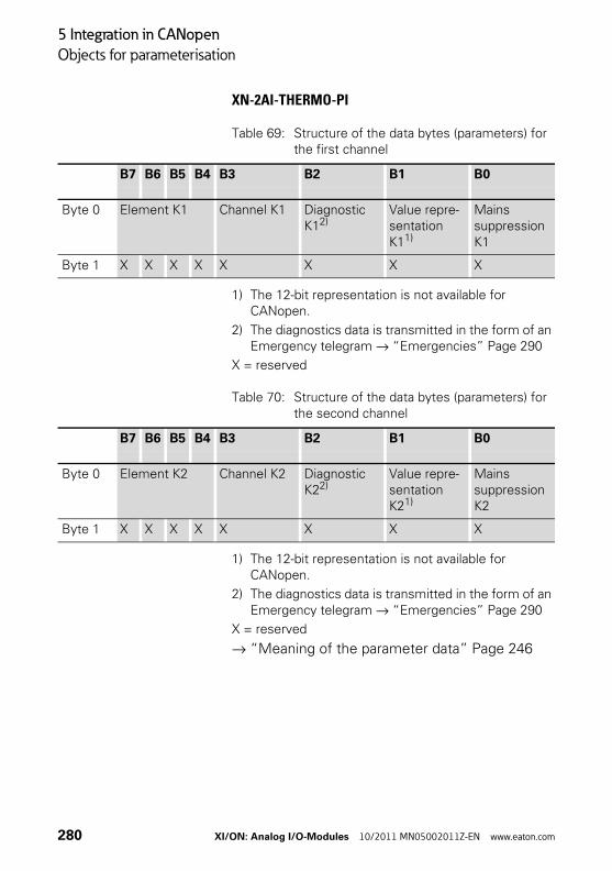
5 Integration in CANopen
Objects for parameterisation
XN-2AI-THERMO-PI
Table 69: Structure of the data bytes (parameters) for the first channel
1) The 12-bit representation is not available for CANopen.
2) The diagnostics data is transmitted in the form of an Emergency telegram → “Emergencies” Page 290
X = reserved
Table 70: Structure of the data bytes (parameters) for the second channel
1) The 12-bit representation is not available for CANopen.
2) The diagnostics data is transmitted in the form of an Emergency telegram → “Emergencies” Page 290
X = reserved
→ “Meaning of the parameter data” Page 246
B7 B6 B5 B4 B3 B2 B1 B0
Byte 0 Element K1 Channel K1 Diagnostic K12)
Value repre-sentation K11)
Mains suppression K1
Byte 1 X X X X X X X X
B7 B6 B5 B4 B3 B2 B1 B0
Byte 0 Element K2 Channel K2 Diagnostic K22)
Value repre-sentation K21)
Mains suppression K2
Byte 1 X X X X X X X X
280 XI/ON: Analog I/O-Modules 10/2011 MN05002011Z-EN www.eaton.com
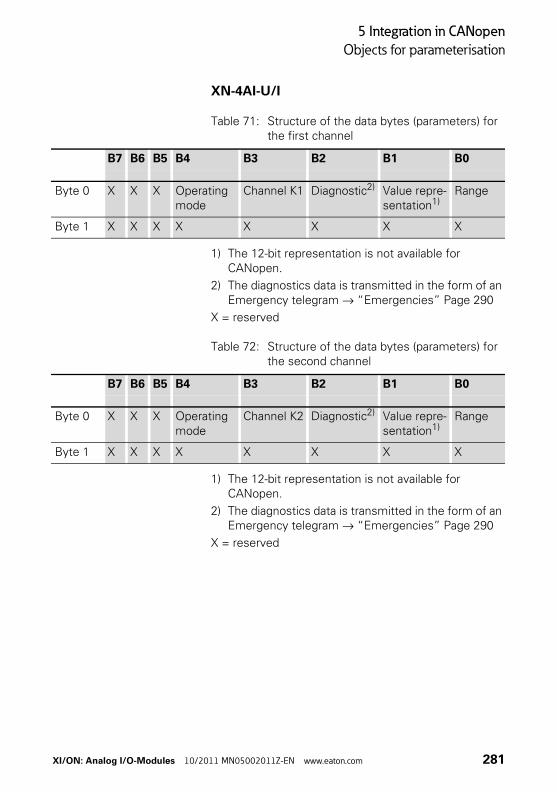
5 Integration in CANopen
Objects for parameterisation
XN-4AI-U/I
Table 71: Structure of the data bytes (parameters) for the first channel
1) The 12-bit representation is not available for CANopen.
2) The diagnostics data is transmitted in the form of an Emergency telegram → “Emergencies” Page 290
X = reserved
Table 72: Structure of the data bytes (parameters) for the second channel
1) The 12-bit representation is not available for CANopen.
2) The diagnostics data is transmitted in the form of an Emergency telegram → “Emergencies” Page 290
X = reserved
B7 B6 B5 B4 B3 B2 B1 B0
Byte 0 X X X Operating mode
Channel K1 Diagnostic2) Value repre-sentation1)
Range
Byte 1 X X X X X X X X
B7 B6 B5 B4 B3 B2 B1 B0
Byte 0 X X X Operating mode
Channel K2 Diagnostic2) Value repre-sentation1)
Range
Byte 1 X X X X X X X X
XI/ON: Analog I/O-Modules 10/2011 MN05002011Z-EN www.eaton.com 281
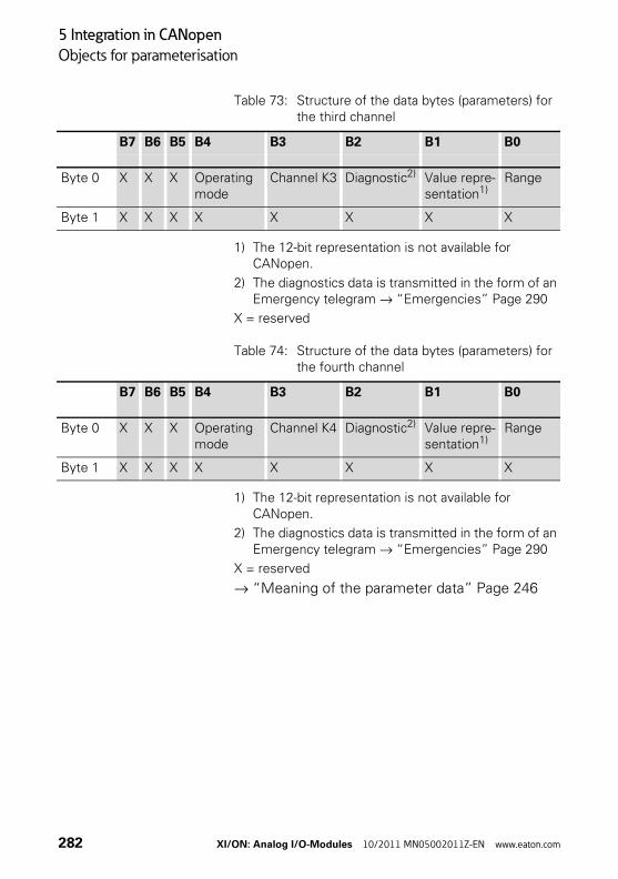
5 Integration in CANopen
Objects for parameterisation
Table 73: Structure of the data bytes (parameters) for the third channel
1) The 12-bit representation is not available for CANopen.
2) The diagnostics data is transmitted in the form of an Emergency telegram → “Emergencies” Page 290
X = reserved
Table 74: Structure of the data bytes (parameters) for the fourth channel
1) The 12-bit representation is not available for CANopen.
2) The diagnostics data is transmitted in the form of an Emergency telegram → “Emergencies” Page 290
X = reserved
→ “Meaning of the parameter data” Page 246
B7 B6 B5 B4 B3 B2 B1 B0
Byte 0 X X X Operating mode
Channel K3 Diagnostic2) Value repre-sentation1)
Range
Byte 1 X X X X X X X X
B7 B6 B5 B4 B3 B2 B1 B0
Byte 0 X X X Operating mode
Channel K4 Diagnostic2) Value repre-sentation1)
Range
Byte 1 X X X X X X X X
282 XI/ON: Analog I/O-Modules 10/2011 MN05002011Z-EN www.eaton.com
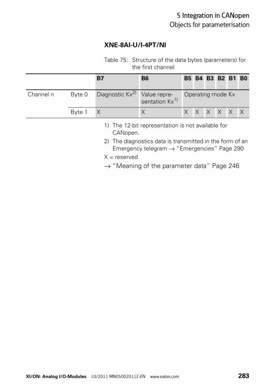
5 Integration in CANopen
Objects for parameterisation
XNE-8AI-U/I-4PT/NI
Table 75: Structure of the data bytes (parameters) for the first channel
1) The 12-bit representation is not available for CANopen.
2) The diagnostics data is transmitted in the form of an Emergency telegram → “Emergencies” Page 290
X = reserved
→ “Meaning of the parameter data” Page 246
B7 B6 B5 B4 B3 B2 B1 B0
Channel n Byte 0 Diagnostic Kx2) Value repre-sentation Kx1)
Operating mode Kx
Byte 1 X X X X X X X X
XI/ON: Analog I/O-Modules 10/2011 MN05002011Z-EN www.eaton.com 283
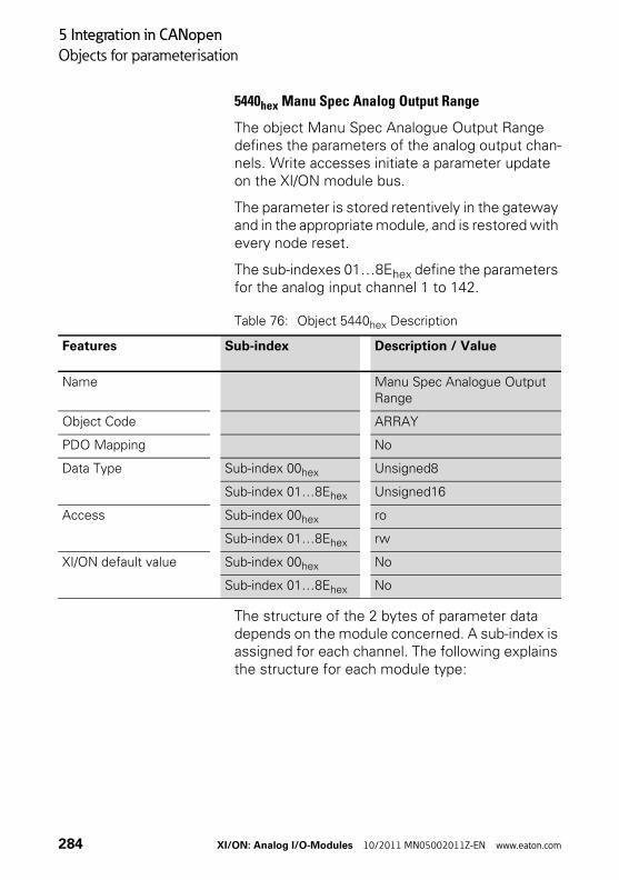
5 Integration in CANopen
Objects for parameterisation
5440hex Manu Spec Analog Output Range
The object Manu Spec Analogue Output Range defines the parameters of the analog output chan-nels. Write accesses initiate a parameter update on the XI/ON module bus.
The parameter is stored retentively in the gateway and in the appropriate module, and is restored with every node reset.
The sub-indexes 01…8Ehex define the parameters for the analog input channel 1 to 142.
Table 76: Object 5440hex Description
The structure of the 2 bytes of parameter data depends on the module concerned. A sub-index is assigned for each channel. The following explains the structure for each module type:
Features Sub-index Description / Value
Name Manu Spec Analogue Output Range
Object Code ARRAY
PDO Mapping No
Data Type Sub-index 00hex Unsigned8
Sub-index 01…8Ehex Unsigned16
Access Sub-index 00hex ro
Sub-index 01…8Ehex rw
XI/ON default value Sub-index 00hex No
Sub-index 01…8Ehex No
284 XI/ON: Analog I/O-Modules 10/2011 MN05002011Z-EN www.eaton.com
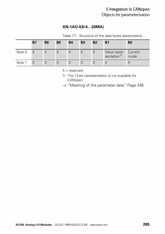
5 Integration in CANopen
Objects for parameterisation
XN-1AO-I(0/4…20MA)
Table 77: Structure of the data bytes (parameters)
X = reserved
1) The 12-bit representation is not available for CANopen.
→ “Meaning of the parameter data” Page 246
B7 B6 B5 B4 B3 B2 B1 B0
Byte 0 X X X X X X Value repre-sentation1)
Current mode
Byte 1 X X X X X X X X
XI/ON: Analog I/O-Modules 10/2011 MN05002011Z-EN www.eaton.com 285
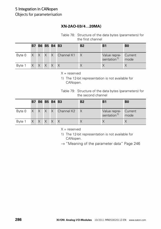
5 Integration in CANopen
Objects for parameterisation
XN-2AO-I(0/4…20MA)
Table 78: Structure of the data bytes (parameters) for the first channel
X = reserved
1) The 12-bit representation is not available for CANopen.
Table 79: Structure of the data bytes (parameters) for the second channel
X = reserved
1) The 12-bit representation is not available for CANopen.
→ “Meaning of the parameter data” Page 246
B7 B6 B5 B4 B3 B2 B1 B0
Byte 0 X X X X Channel K1 X Value repre-sentation1)
Current mode
Byte 1 X X X X X X X X
B7 B6 B5 B4 B3 B2 B1 B0
Byte 0 X X X X Channel K2 X Value repre-sentation1)
Current mode
Byte 1 X X X X X X X X
286 XI/ON: Analog I/O-Modules 10/2011 MN05002011Z-EN www.eaton.com
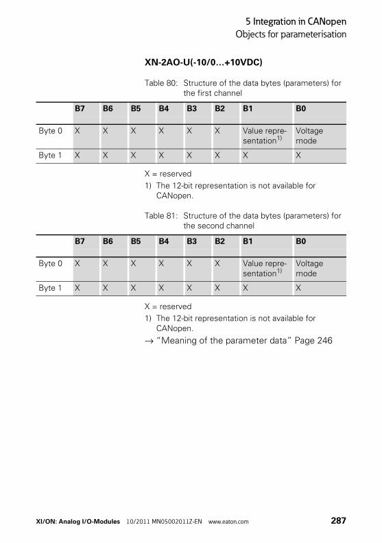
5 Integration in CANopen
Objects for parameterisation
XN-2AO-U(-10/0…+10VDC)
Table 80: Structure of the data bytes (parameters) for the first channel
X = reserved
1) The 12-bit representation is not available for CANopen.
Table 81: Structure of the data bytes (parameters) for the second channel
X = reserved
1) The 12-bit representation is not available for CANopen.
→ “Meaning of the parameter data” Page 246
B7 B6 B5 B4 B3 B2 B1 B0
Byte 0 X X X X X X Value repre-sentation1)
Voltage mode
Byte 1 X X X X X X X X
B7 B6 B5 B4 B3 B2 B1 B0
Byte 0 X X X X X X Value repre-sentation1)
Voltage mode
Byte 1 X X X X X X X X
XI/ON: Analog I/O-Modules 10/2011 MN05002011Z-EN www.eaton.com 287
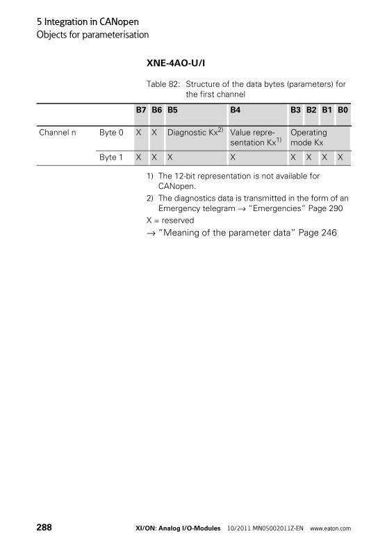
5 Integration in CANopen
Objects for parameterisation
XNE-4AO-U/I
Table 82: Structure of the data bytes (parameters) for the first channel
1) The 12-bit representation is not available for CANopen.
2) The diagnostics data is transmitted in the form of an Emergency telegram → “Emergencies” Page 290
X = reserved
→ “Meaning of the parameter data” Page 246
B7 B6 B5 B4 B3 B2 B1 B0
Channel n Byte 0 X X Diagnostic Kx2) Value repre-sentation Kx1)
Operating mode Kx
Byte 1 X X X X X X X X
288 XI/ON: Analog I/O-Modules 10/2011 MN05002011Z-EN www.eaton.com
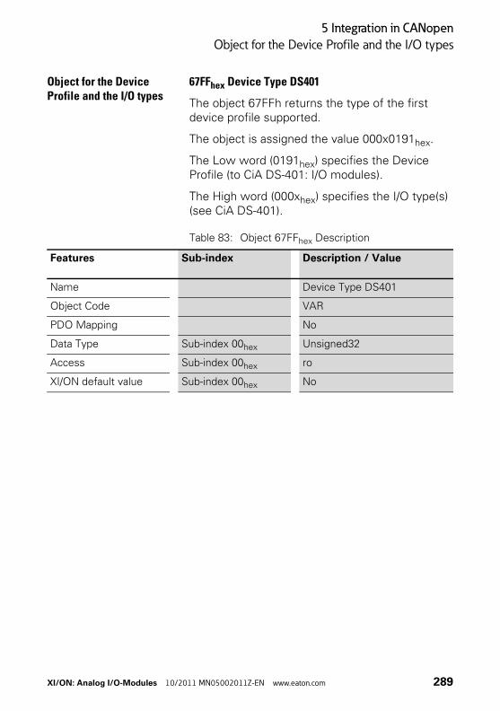
5 Integration in CANopen
Object for the Device Profile and the I/O types
Object for the Device Profile and the I/O types
67FFhex Device Type DS401
The object 67FFh returns the type of the first device profile supported.
The object is assigned the value 000x0191hex.
The Low word (0191hex) specifies the Device Profile (to CiA DS-401: I/O modules).
The High word (000xhex) specifies the I/O type(s) (see CiA DS-401).
Table 83: Object 67FFhex Description
Features Sub-index Description / Value
Name Device Type DS401
Object Code VAR
PDO Mapping No
Data Type Sub-index 00hex Unsigned32
Access Sub-index 00hex ro
XI/ON default value Sub-index 00hex No
XI/ON: Analog I/O-Modules 10/2011 MN05002011Z-EN www.eaton.com 289
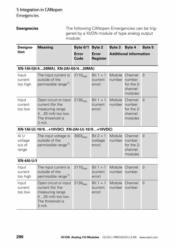
5 Integration in CANopen
Emergencies
Emergencies The following CANopen Emergencies can be trig-gered by a XI/ON module of type analog output module:
Designa-tion
Meaning Byte 0/1 Byte 2 Byte 3 Byte 4 Byte 5
Error Code
Error Register
Additional information
XN-1AI-I(0/4…20MA); XN-2AI-I(0/4…20MA)
Input current too high
The input current is outside of the permissible range1).
2110hex Bit 1 = 1(current error)
Module number
Channel number for the 2-channel modules
0
Input current too low
Open circuit or input current (for the measuring range 4…20 mA) too low. The threshold is 3 mA.
2130hex Bit 1 = 1(current error)
Module number
Channel number for the 2-channel modules
0
XN-1AI-U(-10/0…+10VDC); XN-2AI-U(-10/0…+10VDC)
AI U voltage out of range
The input voltage is outside of the permissible range1).
3003hex Bit 2 = 1(voltage error)
Module number
Channel number for the 2-channel modules
0
XN-4AI-U/I
Input current too high
The input current is outside of the permissible range1).
2110hex Bit 1 = 1(current error)
Module number
Channel number
0
Input current too low
Open circuit or input current (for the measuring range 4…20 mA) too low. The threshold is 3 mA.
2130hex Bit 1 = 1(current error)
Module number
Channel number
0
290 XI/ON: Analog I/O-Modules 10/2011 MN05002011Z-EN www.eaton.com
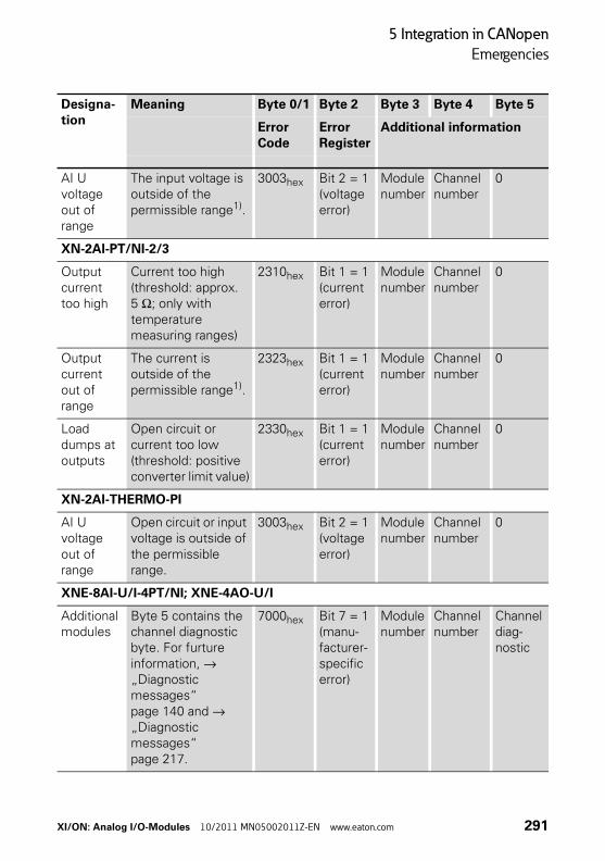
5 Integration in CANopen
Emergencies
AI U voltage out of range
The input voltage is outside of the permissible range1).
3003hex Bit 2 = 1(voltage error)
Module number
Channel number
0
XN-2AI-PT/NI-2/3
Output current too high
Current too high (threshold: approx. 5 Ω; only with temperature measuring ranges)
2310hex Bit 1 = 1(current error)
Module number
Channel number
0
Output current out of range
The current is outside of the permissible range1).
2323hex Bit 1 = 1(current error)
Module number
Channel number
0
Load dumps at outputs
Open circuit or current too low (threshold: positive converter limit value)
2330hex Bit 1 = 1(current error)
Module number
Channel number
0
XN-2AI-THERMO-PI
AI U voltage out of range
Open circuit or input voltage is outside of the permissible range.
3003hex Bit 2 = 1(voltage error)
Module number
Channel number
0
XNE-8AI-U/I-4PT/NI; XNE-4AO-U/I
Additional modules
Byte 5 contains the channel diagnostic byte. For furture information, → „Diagnostic messages“ page 140 and → „Diagnostic messages“ page 217.
7000hex Bit 7 = 1(manu-facturer-specific error)
Module number
Channel number
Channel diag-nostic
Designa-tion
Meaning Byte 0/1 Byte 2 Byte 3 Byte 4 Byte 5
Error Code
Error Register
Additional information
XI/ON: Analog I/O-Modules 10/2011 MN05002011Z-EN www.eaton.com 291
5 Integration in CANopen
Emergencies
1) The threshold for this error message is 1 % over the upper measuring range value or 1 % below the lower measuring range value.Refer to the sections “Diagnostic messages” of the corresponding module type for information on the diagnostic options for each module type .
Bytes 6 and 7 of the Emergency Frame are not used, and therefore always 0.
292 XI/ON: Analog I/O-Modules 10/2011 MN05002011Z-EN www.eaton.com
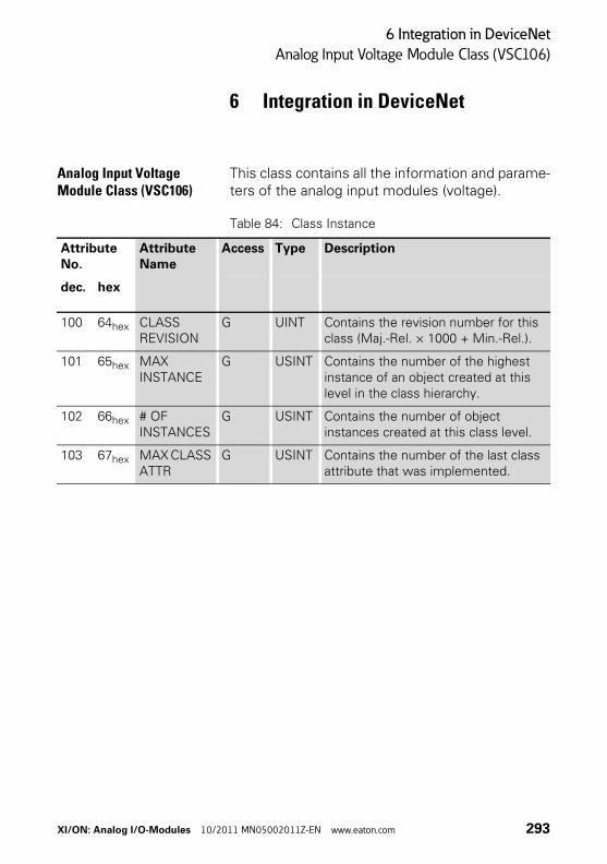
6 Integration in DeviceNet
Analog Input Voltage Module Class (VSC106)
6 Integration in DeviceNet
Analog Input Voltage Module Class (VSC106)
This class contains all the information and parame-ters of the analog input modules (voltage).
Table 84: Class Instance
Attribute No.
Attribute Name
Access Type Description
dec. hex
100 64hex CLASS REVISION
G UINT Contains the revision number for this class (Maj.-Rel. × 1000 + Min.-Rel.).
101 65hex MAX INSTANCE
G USINT Contains the number of the highest instance of an object created at this level in the class hierarchy.
102 66hex # OF INSTANCES
G USINT Contains the number of object instances created at this class level.
103 67hex MAX CLASS ATTR
G USINT Contains the number of the last class attribute that was implemented.
XI/ON: Analog I/O-Modules 10/2011 MN05002011Z-EN www.eaton.com 293
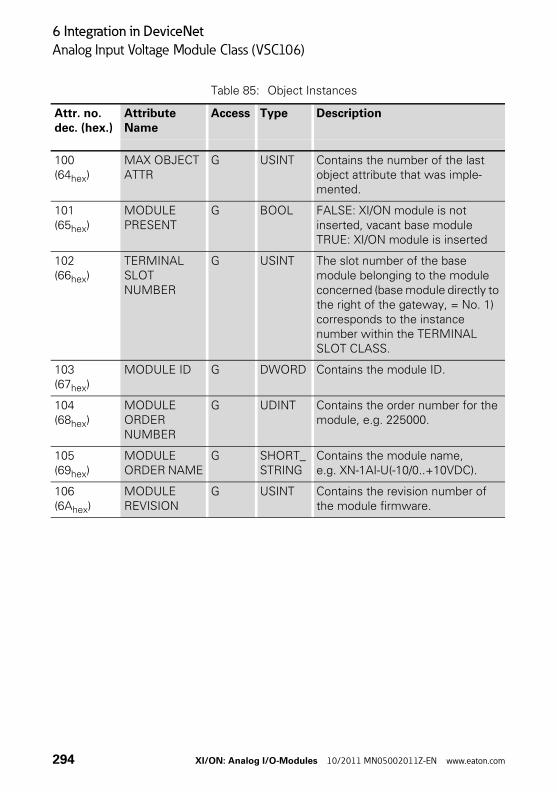
6 Integration in DeviceNet
Analog Input Voltage Module Class (VSC106)
Table 85: Object Instances
Attr. no.dec. (hex.)
Attribute Name
Access Type Description
100(64hex)
MAX OBJECT ATTR
G USINT Contains the number of the last object attribute that was imple-mented.
101(65hex)
MODULE PRESENT
G BOOL FALSE: XI/ON module is not inserted, vacant base module TRUE: XI/ON module is inserted
102(66hex)
TERMINAL SLOT NUMBER
G USINT The slot number of the base module belonging to the module concerned (base module directly to the right of the gateway, = No. 1) corresponds to the instance number within the TERMINAL SLOT CLASS.
103(67hex)
MODULE ID G DWORD Contains the module ID.
104(68hex)
MODULE ORDER NUMBER
G UDINT Contains the order number for the module, e.g. 225000.
105(69hex)
MODULE ORDER NAME
G SHORT_STRING
Contains the module name, e.g. XN-1AI-U(-10/0..+10VDC).
106(6Ahex)
MODULE REVISION
G USINT Contains the revision number of the module firmware.
294 XI/ON: Analog I/O-Modules 10/2011 MN05002011Z-EN www.eaton.com

6 Integration in DeviceNet
Analog Input Voltage Module Class (VSC106)
107(6Bhex)
MODULE TYPE ID
G ENUM USINT
Provides information on the module type:0 (00hex) unknown module type1 (01hex) digital I/O module17 (11hex) analog module I/O voltage18 (12hex) analog module I/O current (current/voltage)19 (13hex) analog module PT temperature20 (14hex) analog module thermo temperature33 (21hex) 16-bit counter module34 (22hex) 32-bit counter module40 (28hex) SSI module49 (31hex) Motor starter module as DOL or reversing starter50 (32hex) electronic motor starter65 (41hex) RS232 module66 (42hex) RS485/422 module67 (43hex) TTY module
108(6Chex)
MODULE COMMAND INTERFACE
G/S ARRAY Control interface of the XI/ON module.ARRAY OF:BYTE: control byte sequence
109(6Dhex)
MODULE RESPONSE INTERFACE
G ARRAY Message interface for the XI/ON module.ARRAY OF:BYTE: message byte sequence
110(6Ehex)
MODULE REGISTERED INDEX
G ENUM USINT
Contains the index number found in all module lists.
111(6Fhex)
NUMBER OF SUPPORTED CHANNELS
G USINT Indicates the number of analog input channels supported by this module instance.
Attr. no.dec. (hex.)
Attribute Name
Access Type Description
XI/ON: Analog I/O-Modules 10/2011 MN05002011Z-EN www.eaton.com 295
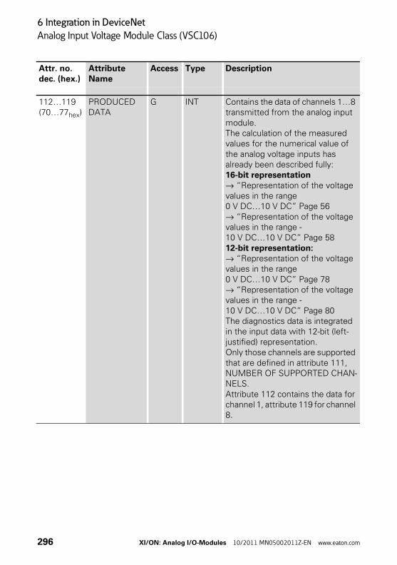
6 Integration in DeviceNet
Analog Input Voltage Module Class (VSC106)
112…119(70…77hex)
PRODUCED DATA
G INT Contains the data of channels 1…8 transmitted from the analog input module.The calculation of the measured values for the numerical value of the analog voltage inputs has already been described fully: 16-bit representation→ “Representation of the voltage values in the range 0 V DC…10 V DC” Page 56→ “Representation of the voltage values in the range -10 V DC…10 V DC” Page 5812-bit representation:→ “Representation of the voltage values in the range 0 V DC…10 V DC” Page 78→ “Representation of the voltage values in the range -10 V DC…10 V DC” Page 80The diagnostics data is integrated in the input data with 12-bit (left-justified) representation.Only those channels are supported that are defined in attribute 111, NUMBER OF SUPPORTED CHAN-NELS.Attribute 112 contains the data for channel 1, attribute 119 for channel 8.
Attr. no.dec. (hex.)
Attribute Name
Access Type Description
296 XI/ON: Analog I/O-Modules 10/2011 MN05002011Z-EN www.eaton.com
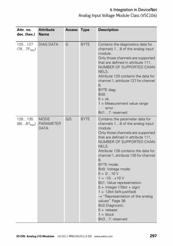
6 Integration in DeviceNet
Analog Input Voltage Module Class (VSC106)
120…127(78…7Fhex)
DIAG DATA G BYTE Contains the diagnostics data for channels 1…8 of the analog input module. Only those channels are supported that are defined in attribute 111, NUMBER OF SUPPORTED CHAN-NELS.Attribute 120 contains the data for channel 1, attribute 127 for channel 8.BYTE diag:Bit0:0 = ok, 1 = Measurement value range
errorBit1…7: reserved
128…135(80…87hex)
MODE PARAMETER DATA
G/S BYTE Contains the parameter data for channels 1…8 of the analog input module. Only those channels are supported that are defined in attribute 111, NUMBER OF SUPPORTED CHAN-NELS.Attribute 128 contains the data for channel 1, attribute 135 for channel 8. BYTE mode:Bit0: Voltage mode:0 = 0…10 V1 = -10…+10 VBit1: Value representation:0 = Integer (15bit + sign) 1 = 12bit (left-justified) → “Representation of the analog values” Page 38Bit2:Diagnostic:0 = release1 = blockBit3…7: reserved
Attr. no.dec. (hex.)
Attribute Name
Access Type Description
XI/ON: Analog I/O-Modules 10/2011 MN05002011Z-EN www.eaton.com 297
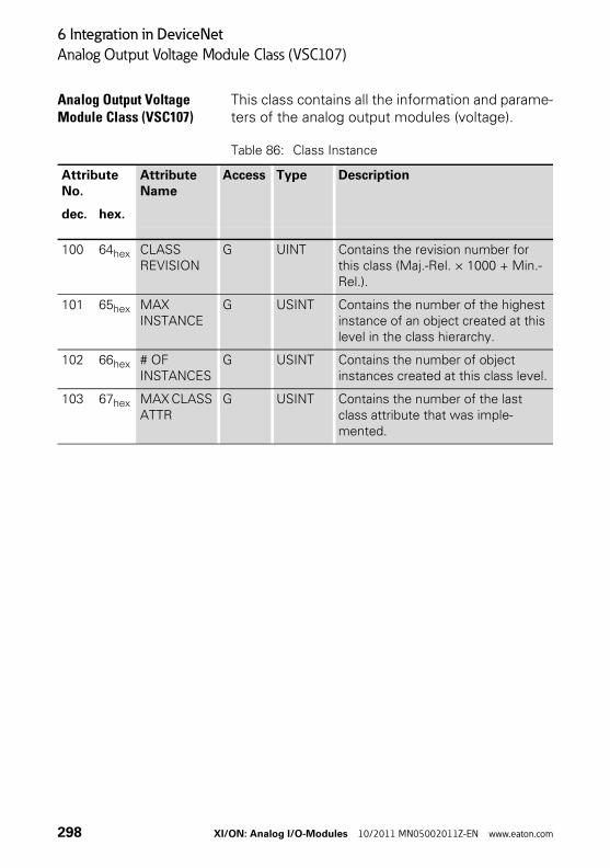
6 Integration in DeviceNet
Analog Output Voltage Module Class (VSC107)
Analog Output Voltage Module Class (VSC107)
This class contains all the information and parame-ters of the analog output modules (voltage).
Table 86: Class Instance
Attribute No.
Attribute Name
Access Type Description
dec. hex.
100 64hex CLASS REVISION
G UINT Contains the revision number for this class (Maj.-Rel. × 1000 + Min.-Rel.).
101 65hex MAX INSTANCE
G USINT Contains the number of the highest instance of an object created at this level in the class hierarchy.
102 66hex # OF INSTANCES
G USINT Contains the number of object instances created at this class level.
103 67hex MAX CLASS ATTR
G USINT Contains the number of the last class attribute that was imple-mented.
298 XI/ON: Analog I/O-Modules 10/2011 MN05002011Z-EN www.eaton.com
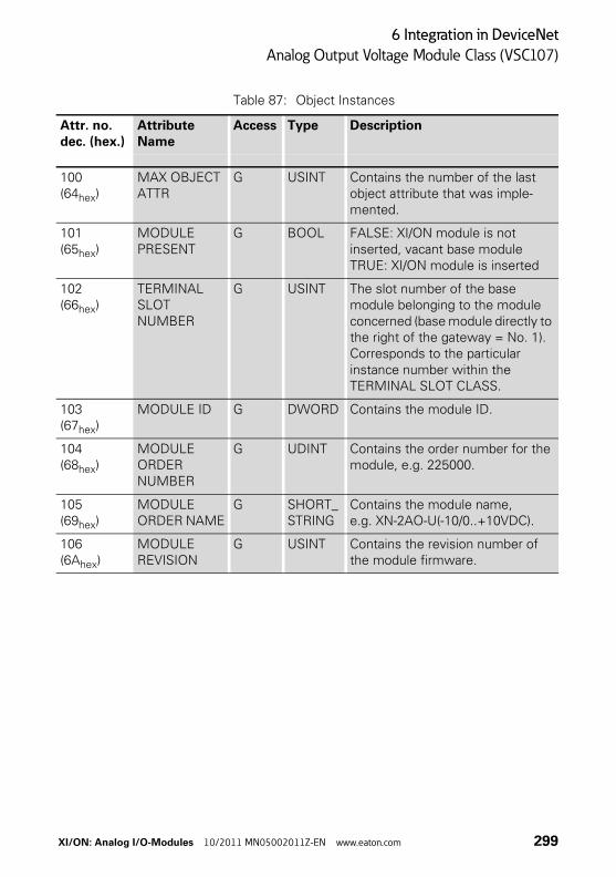
6 Integration in DeviceNet
Analog Output Voltage Module Class (VSC107)
Table 87: Object Instances
Attr. no.dec. (hex.)
Attribute Name
Access Type Description
100(64hex)
MAX OBJECT ATTR
G USINT Contains the number of the last object attribute that was imple-mented.
101(65hex)
MODULE PRESENT
G BOOL FALSE: XI/ON module is not inserted, vacant base moduleTRUE: XI/ON module is inserted
102(66hex)
TERMINAL SLOT NUMBER
G USINT The slot number of the base module belonging to the module concerned (base module directly to the right of the gateway = No. 1). Corresponds to the particular instance number within the TERMINAL SLOT CLASS.
103(67hex)
MODULE ID G DWORD Contains the module ID.
104(68hex)
MODULE ORDER NUMBER
G UDINT Contains the order number for the module, e.g. 225000.
105(69hex)
MODULE ORDER NAME
G SHORT_STRING
Contains the module name, e.g. XN-2AO-U(-10/0..+10VDC).
106(6Ahex)
MODULE REVISION
G USINT Contains the revision number of the module firmware.
XI/ON: Analog I/O-Modules 10/2011 MN05002011Z-EN www.eaton.com 299
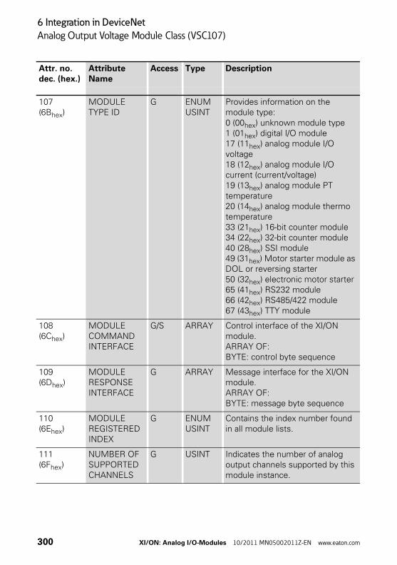
6 Integration in DeviceNet
Analog Output Voltage Module Class (VSC107)
107(6Bhex)
MODULE TYPE ID
G ENUM USINT
Provides information on the module type:0 (00hex) unknown module type1 (01hex) digital I/O module17 (11hex) analog module I/O voltage18 (12hex) analog module I/O current (current/voltage)19 (13hex) analog module PT temperature20 (14hex) analog module thermo temperature33 (21hex) 16-bit counter module34 (22hex) 32-bit counter module40 (28hex) SSI module49 (31hex) Motor starter module as DOL or reversing starter50 (32hex) electronic motor starter65 (41hex) RS232 module66 (42hex) RS485/422 module67 (43hex) TTY module
108(6Chex)
MODULE COMMAND INTERFACE
G/S ARRAY Control interface of the XI/ON module.ARRAY OF:BYTE: control byte sequence
109(6Dhex)
MODULE RESPONSE INTERFACE
G ARRAY Message interface for the XI/ON module.ARRAY OF:BYTE: message byte sequence
110(6Ehex)
MODULE REGISTERED INDEX
G ENUM USINT
Contains the index number found in all module lists.
111(6Fhex)
NUMBER OF SUPPORTED CHANNELS
G USINT Indicates the number of analog output channels supported by this module instance.
Attr. no.dec. (hex.)
Attribute Name
Access Type Description
300 XI/ON: Analog I/O-Modules 10/2011 MN05002011Z-EN www.eaton.com
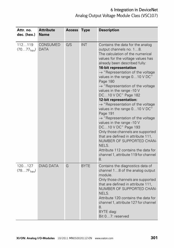
6 Integration in DeviceNet
Analog Output Voltage Module Class (VSC107)
112…119(70…77hex)
CONSUMED DATA
G/S INT Contains the data for the analog output channels no. 1…8.The calculation of the numerical values for the voltage values has already been described fully: 16-bit representation→ “Representation of the voltage values in the range 0…10 V DC” Page 180→ “Representation of the voltage values in the range -10 V DC…10 V DC” Page 18212-bit representation:→ “Representation of the voltage values in the range 0…10 V DC” Page 191→ “Representation of the voltage values in the range -10 V DC…10 V DC” Page 193Only those channels are supported that are defined in attribute 111, NUMBER OF SUPPORTED CHAN-NELS.Attribute 112 contains the data for channel 1, attribute 119 for channel 8.
120…127(78…7Fhex)
DIAG DATA G BYTE Contains the diagnostics data of channel 1…8 of the analog output module. Only those channels are supported that are defined in attribute 111, NUMBER OF SUPPORTED CHAN-NELS. Attribute 120 contains the data for channel 1, attribute 127 for channel 8.BYTE diag:Bit 0…7: reserved
Attr. no.dec. (hex.)
Attribute Name
Access Type Description
XI/ON: Analog I/O-Modules 10/2011 MN05002011Z-EN www.eaton.com 301
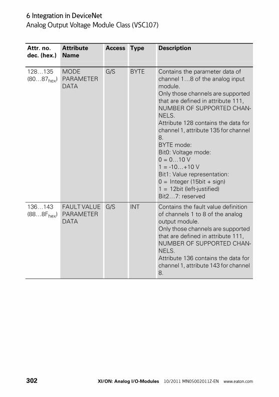
6 Integration in DeviceNet
Analog Output Voltage Module Class (VSC107)
128…135(80…87hex)
MODE PARAMETER DATA
G/S BYTE Contains the parameter data of channel 1…8 of the analog input module. Only those channels are supported that are defined in attribute 111, NUMBER OF SUPPORTED CHAN-NELS.Attribute 128 contains the data for channel 1, attribute 135 for channel 8. BYTE mode:Bit0: Voltage mode:0 = 0…10 V1 = -10…+10 VBit1: Value representation:0 = Integer (15bit + sign) 1 = 12bit (left-justified)Bit2…7: reserved
136…143(88…8Fhex)
FAULT VALUE PARAMETER DATA
G/S INT Contains the fault value definition of channels 1 to 8 of the analog output module.Only those channels are supported that are defined in attribute 111, NUMBER OF SUPPORTED CHAN-NELS.Attribute 136 contains the data for channel 1, attribute 143 for channel 8.
Attr. no.dec. (hex.)
Attribute Name
Access Type Description
302 XI/ON: Analog I/O-Modules 10/2011 MN05002011Z-EN www.eaton.com
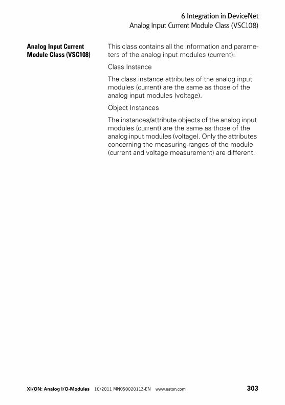
6 Integration in DeviceNet
Analog Input Current Module Class (VSC108)
Analog Input Current Module Class (VSC108)
This class contains all the information and parame-ters of the analog input modules (current).
Class Instance
The class instance attributes of the analog input modules (current) are the same as those of the analog input modules (voltage).
Object Instances
The instances/attribute objects of the analog input modules (current) are the same as those of the analog input modules (voltage). Only the attributes concerning the measuring ranges of the module (current and voltage measurement) are different.
XI/ON: Analog I/O-Modules 10/2011 MN05002011Z-EN www.eaton.com 303

6 Integration in DeviceNet
Analog Input Current Module Class (VSC108)
Table 88: Object Instances
Attr. no.dec. (hex.)
Attribute Name
Access Type Description
112…119(70…77hex)
PRODUCED DATA
G INT Contains the data of channels 1 to 8 transmitted from the analog input module.The calculation of the measured values for the numerical value of the analog current inputs has already been described fully: 16-bit representation→ “Representation of current values in the range 0 mA…20 mA” Page 40→ “Representation of current values in the range 4 mA…20 mA” Page 4212-bit representation→ “Representation of the current values in the range 0…20 mA” Page 62→ “Representation of the current values in the range 4…20 mA” Page 64The diagnostics data is integrated in the input data with 12-bit (left-justified) representation.Only those channels are supported that are defined in attribute 111, NUMBER OF SUPPORTED CHAN-NELS. Attribute 112 contains the data for channel 1, attribute 119 for channel 8.
304 XI/ON: Analog I/O-Modules 10/2011 MN05002011Z-EN www.eaton.com
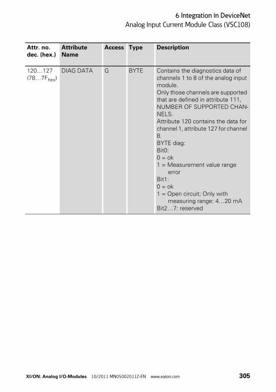
6 Integration in DeviceNet
Analog Input Current Module Class (VSC108)
120…127(78…7Fhex)
DIAG DATA G BYTE Contains the diagnostics data of channels 1 to 8 of the analog input module. Only those channels are supported that are defined in attribute 111, NUMBER OF SUPPORTED CHAN-NELS. Attribute 120 contains the data for channel 1, attribute 127 for channel 8.BYTE diag:Bit0: 0 = ok1 = Measurement value range
errorBit1: 0 = ok1 = Open circuit; Only with
measuring range: 4…20 mABit2…7: reserved
Attr. no.dec. (hex.)
Attribute Name
Access Type Description
XI/ON: Analog I/O-Modules 10/2011 MN05002011Z-EN www.eaton.com 305
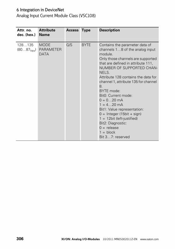
6 Integration in DeviceNet
Analog Input Current Module Class (VSC108)
128…135(80…87hex)
MODE PARAMETER DATA
G/S BYTE Contains the parameter data of channels 1…8 of the analog input module. Only those channels are supported that are defined in attribute 111, NUMBER OF SUPPORTED CHAN-NELS.Attribute 128 contains the data for channel 1, attribute 135 for channel 8. BYTE mode:Bit0: Current mode:0 = 0…20 mA1 = 4…20 mABit1: Value representation:0 = Integer (15bit + sign) 1 = 12bit (left-justified)Bit2: Diagnostic:0 = release1 = blockBit 3…7: reserved
Attr. no.dec. (hex.)
Attribute Name
Access Type Description
306 XI/ON: Analog I/O-Modules 10/2011 MN05002011Z-EN www.eaton.com

6 Integration in DeviceNet
Analog Output Current Module Class (VSC109)
Analog Output Current Module Class (VSC109)
This class contains all the information and parame-ters of the analog output modules (current).
Class Instance
The class instance attributes of the analog output modules (current) are the same as those of the analog output modules (voltage).
Object Instances
The instance/attribute object of the analog output modules (current) is the same as those of the analog output modules (voltage). Only the attri-butes to do with the measuring ranges of the module (current and voltage measurement) are different.
XI/ON: Analog I/O-Modules 10/2011 MN05002011Z-EN www.eaton.com 307
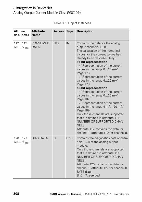
6 Integration in DeviceNet
Analog Output Current Module Class (VSC109)
Table 89: Object Instances
Attr. no.dec. (hex.)
Attribute Name
Access Type Description
112…119(70…77hex)
CONSUMED DATA
G/S INT Contains the data for the analog output channels 1…8.The calculation of the numerical values for the current values has already been described fully: 16-bit representation→ “Representation of the current values in the range 0…20 mA” Page 176→ “Representation of the current values in the range 4…20 mA” Page 17812-bit representation→ “Representation of the current values in the range 0…20 mA” Page 187→ “Representation of the current values in the range 4 mA…20 mA” Page 189Only those channels are supported that are defined in attribute 111, NUMBER OF SUPPORTED CHAN-NELS.Attribute 112 contains the data for channel 1, attribute 119 for channel 8.
120…127(78…7Fhex)
DIAG DATA G BYTE Contains the diagnostics data of chan-nels 1…8 of the analog output module.Only those channels are supported that are defined in attribute 111, NUMBER OF SUPPORTED CHAN-NELS.Attribute 120 contains the data for channel 1, attribute 127 for channel 8.BYTE diag:Bit0…7:reserved
308 XI/ON: Analog I/O-Modules 10/2011 MN05002011Z-EN www.eaton.com
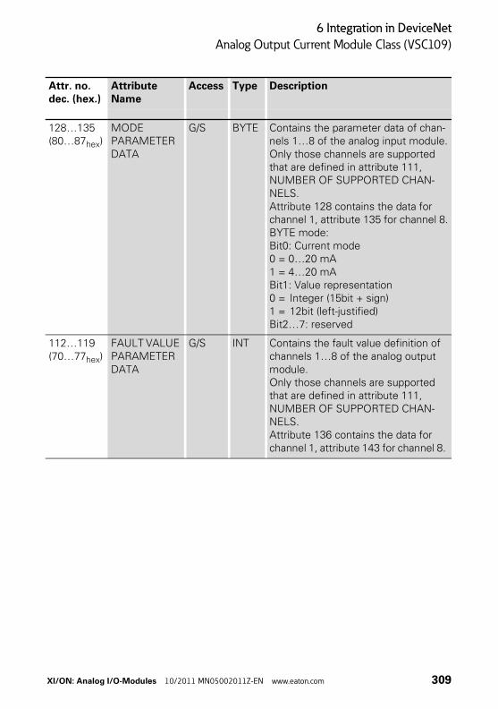
6 Integration in DeviceNet
Analog Output Current Module Class (VSC109)
128…135(80…87hex)
MODE PARAMETER DATA
G/S BYTE Contains the parameter data of chan-nels 1…8 of the analog input module.Only those channels are supported that are defined in attribute 111, NUMBER OF SUPPORTED CHAN-NELS.Attribute 128 contains the data for channel 1, attribute 135 for channel 8.BYTE mode:Bit0: Current mode0 = 0…20 mA1 = 4…20 mABit1: Value representation0 = Integer (15bit + sign) 1 = 12bit (left-justified)Bit2…7: reserved
112…119(70…77hex)
FAULT VALUE PARAMETER DATA
G/S INT Contains the fault value definition of channels 1…8 of the analog output module.Only those channels are supported that are defined in attribute 111, NUMBER OF SUPPORTED CHAN-NELS.Attribute 136 contains the data for channel 1, attribute 143 for channel 8.
Attr. no.dec. (hex.)
Attribute Name
Access Type Description
XI/ON: Analog I/O-Modules 10/2011 MN05002011Z-EN www.eaton.com 309
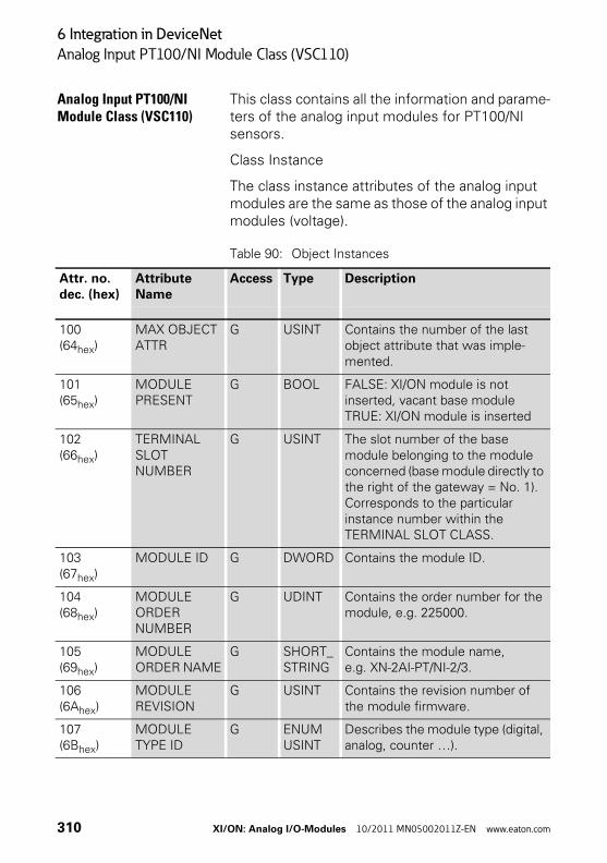
6 Integration in DeviceNet
Analog Input PT100/NI Module Class (VSC110)
Analog Input PT100/NI Module Class (VSC110)
This class contains all the information and parame-ters of the analog input modules for PT100/NI sensors.
Class Instance
The class instance attributes of the analog input modules are the same as those of the analog input modules (voltage).
Table 90: Object Instances
Attr. no.dec. (hex)
Attribute Name
Access Type Description
100(64hex)
MAX OBJECT ATTR
G USINT Contains the number of the last object attribute that was imple-mented.
101(65hex)
MODULE PRESENT
G BOOL FALSE: XI/ON module is not inserted, vacant base moduleTRUE: XI/ON module is inserted
102(66hex)
TERMINAL SLOT NUMBER
G USINT The slot number of the base module belonging to the module concerned (base module directly to the right of the gateway = No. 1).Corresponds to the particular instance number within the TERMINAL SLOT CLASS.
103(67hex)
MODULE ID G DWORD Contains the module ID.
104(68hex)
MODULE ORDER NUMBER
G UDINT Contains the order number for the module, e.g. 225000.
105(69hex)
MODULE ORDER NAME
G SHORT_STRING
Contains the module name, e.g. XN-2AI-PT/NI-2/3.
106(6Ahex)
MODULE REVISION
G USINT Contains the revision number of the module firmware.
107(6Bhex)
MODULE TYPE ID
G ENUM USINT
Describes the module type (digital, analog, counter …).
310 XI/ON: Analog I/O-Modules 10/2011 MN05002011Z-EN www.eaton.com
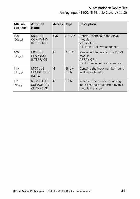
6 Integration in DeviceNet
Analog Input PT100/NI Module Class (VSC110)
108(6Chex)
MODULE COMMAND INTERFACE
G/S ARRAY Control interface of the XI/ON module.ARRAY OF:BYTE: control byte sequence
109(6Dhex)
MODULE RESPONSE INTERFACE
G ARRAY Message interface for the XI/ON module.ARRAY OF:BYTE: message byte sequence
110(6Ehex)
MODULE REGISTERED INDEX
G ENUM USINT
Contains the index number found in all module lists.
111(6Fhex)
NUMBER OF SUPPORTED CHANNELS
G USINT Indicates the number of analog input channels supported by this module instance.
Attr. no.dec. (hex)
Attribute Name
Access Type Description
XI/ON: Analog I/O-Modules 10/2011 MN05002011Z-EN www.eaton.com 311
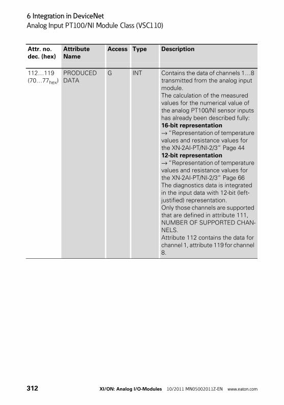
6 Integration in DeviceNet
Analog Input PT100/NI Module Class (VSC110)
112…119(70…77hex)
PRODUCED DATA
G INT Contains the data of channels 1…8 transmitted from the analog input module.The calculation of the measured values for the numerical value of the analog PT100/NI sensor inputs has already been described fully: 16-bit representation→ “Representation of temperature values and resistance values for the XN-2AI-PT/NI-2/3” Page 4412-bit representation→ “Representation of temperature values and resistance values for the XN-2AI-PT/NI-2/3” Page 66The diagnostics data is integrated in the input data with 12-bit (left-justified) representation.Only those channels are supported that are defined in attribute 111, NUMBER OF SUPPORTED CHAN-NELS.Attribute 112 contains the data for channel 1, attribute 119 for channel 8.
Attr. no.dec. (hex)
Attribute Name
Access Type Description
312 XI/ON: Analog I/O-Modules 10/2011 MN05002011Z-EN www.eaton.com
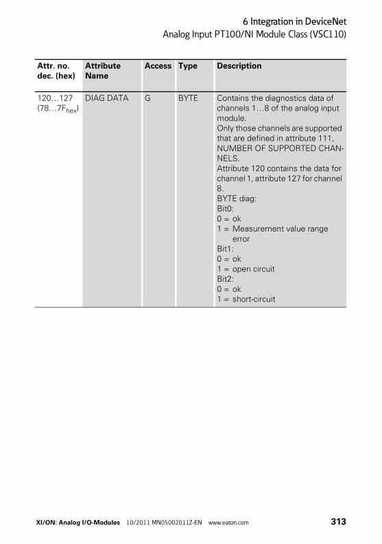
6 Integration in DeviceNet
Analog Input PT100/NI Module Class (VSC110)
120…127(78…7Fhex)
DIAG DATA G BYTE Contains the diagnostics data of channels 1…8 of the analog input module. Only those channels are supported that are defined in attribute 111, NUMBER OF SUPPORTED CHAN-NELS. Attribute 120 contains the data for channel 1, attribute 127 for channel 8.BYTE diag:Bit0:0 = ok1 = Measurement value range
errorBit1:0 = ok1 = open circuitBit2:0 = ok1 = short-circuit
Attr. no.dec. (hex)
Attribute Name
Access Type Description
XI/ON: Analog I/O-Modules 10/2011 MN05002011Z-EN www.eaton.com 313
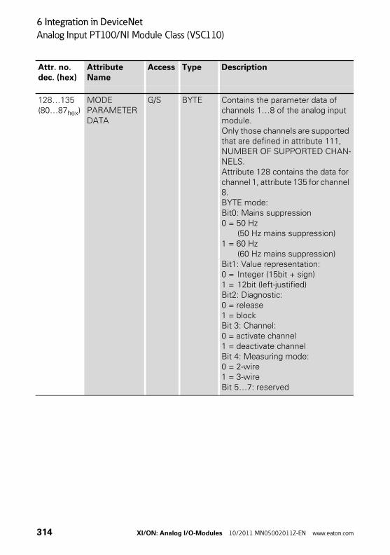
6 Integration in DeviceNet
Analog Input PT100/NI Module Class (VSC110)
128…135(80…87hex)
MODE PARAMETER DATA
G/S BYTE Contains the parameter data of channels 1…8 of the analog input module.Only those channels are supported that are defined in attribute 111, NUMBER OF SUPPORTED CHAN-NELS.Attribute 128 contains the data for channel 1, attribute 135 for channel 8.BYTE mode:Bit0: Mains suppression0 = 50 Hz
(50 Hz mains suppression)1 = 60 Hz
(60 Hz mains suppression)Bit1: Value representation:0 = Integer (15bit + sign) 1 = 12bit (left-justified)Bit2: Diagnostic:0 = release1 = blockBit 3: Channel:0 = activate channel1 = deactivate channelBit 4: Measuring mode:0 = 2-wire1 = 3-wireBit 5…7: reserved
Attr. no.dec. (hex)
Attribute Name
Access Type Description
314 XI/ON: Analog I/O-Modules 10/2011 MN05002011Z-EN www.eaton.com
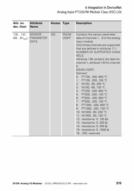
6 Integration in DeviceNet
Analog Input PT100/NI Module Class (VSC110)
136…143(88…8Fhex)
SENSOR PARAMETER DATA
G/S ENUM USINT
Contains the sensor parameter data of channels 1…8 of the analog input module.Only those channels are supported that are defined in attribute 111, NUMBER OF SUPPORTED CHAN-NELS.Attribute 136 contains the data for channel 1, attribute 143 for channel 8.ENUM USINT:Element:0: PT100, -200..850 °C1: PT100, -200..150 °C2: NI100, -60..250 °C3: NI100, -60..150 °C4: PT200, -200..850 °C5: PT200, -200..150 °C6: PT500, -200..850 °C7: PT500, -200..150 °C8: PT1000, -200..850 °C9: PT1000, -200..150 °C10: NI1000, -60..250 °C11: NI1000, -60..150 °C12: resistance: 0..100 Ω)13: resistance: 0..200 Ω14: resistance: 0..400 Ω15: resistance: 0..1000 Ω16…255: reserved
Attr. no.dec. (hex)
Attribute Name
Access Type Description
XI/ON: Analog I/O-Modules 10/2011 MN05002011Z-EN www.eaton.com 315
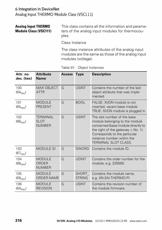
6 Integration in DeviceNet
Analog Input THERMO Module Class (VSC111)
Analog Input THERMO Module Class (VSC111)
This class contains all the information and parame-ters of the analog input modules for thermocou-ples.
Class Instance
The class instance attributes of the analog input modules are the same as those of the analog input modules (voltage).
Table 91: Object Instances
Attr. no.dec. (hex)
Attribute Name
Access Type Description
100(64hex)
MAX OBJECT ATTR
G USINT Contains the number of the last object attribute that was imple-mented.
101(65hex)
MODULE PRESENT
G BOOL FALSE: XI/ON module is not inserted, vacant base moduleTRUE: XI/ON module is plugged in
102(66hex)
TERMINAL SLOT NUMBER
G USINT The slot number of the base module belonging to the module concerned (base module directly to the right of the gateway = No. 1). Corresponds to the particular instance number within the TERMINAL SLOT CLASS.
103(67hex)
MODULE ID G DWORD Contains the module ID.
104(68hex)
MODULE ORDER NUMBER
G UDINT Contains the order number for the module, e.g. 225000.
105(69hex)
MODULE ORDER NAME
G SHORT_STRING
Contains the module name, e.g. XN-2AI-THERMO-PI.
106(6Ahex)
MODULE REVISION
G USINT Contains the revision number of the module firmware.
316 XI/ON: Analog I/O-Modules 10/2011 MN05002011Z-EN www.eaton.com
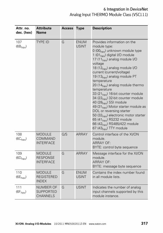
6 Integration in DeviceNet
Analog Input THERMO Module Class (VSC111)
107(6Bhex)
TYPE ID G ENUM USINT
Provides information on the module type:0 (00hex) unknown module type1 (01hex) digital I/O module17 (11hex) analog module I/O voltage18 (12hex) analog module I/O current (current/voltage)19 (13hex) analog module PT temperature20 (14hex) analog module thermo temperature33 (21hex) 16-bit counter module34 (22hex) 32-bit counter module40 (28hex) SSI module49 (31hex) Motor starter module as DOL or reversing starter50 (32hex) electronic motor starter65 (41hex) RS232 module66 (42hex) RS485/422 module67 (43hex) TTY module
108(6Chex)
MODULE COMMAND INTERFACE
G/S ARRAY Control interface of the XI/ON module.ARRAY OF:BYTE: control byte sequence
109(6Dhex)
MODULE RESPONSE INTERFACE
G ARRAY Message interface for the XI/ON module.ARRAY OF:BYTE: message byte sequence
110(6Ehex)
MODULE REGISTERED INDEX
G ENUM USINT
Contains the index number found in all module lists.
111(6Fhex)
NUMBER OF SUPPORTED CHANNELS
G USINT Indicates the number of analog input channels supported by this module instance.
Attr. no.dec. (hex)
Attribute Name
Access Type Description
XI/ON: Analog I/O-Modules 10/2011 MN05002011Z-EN www.eaton.com 317
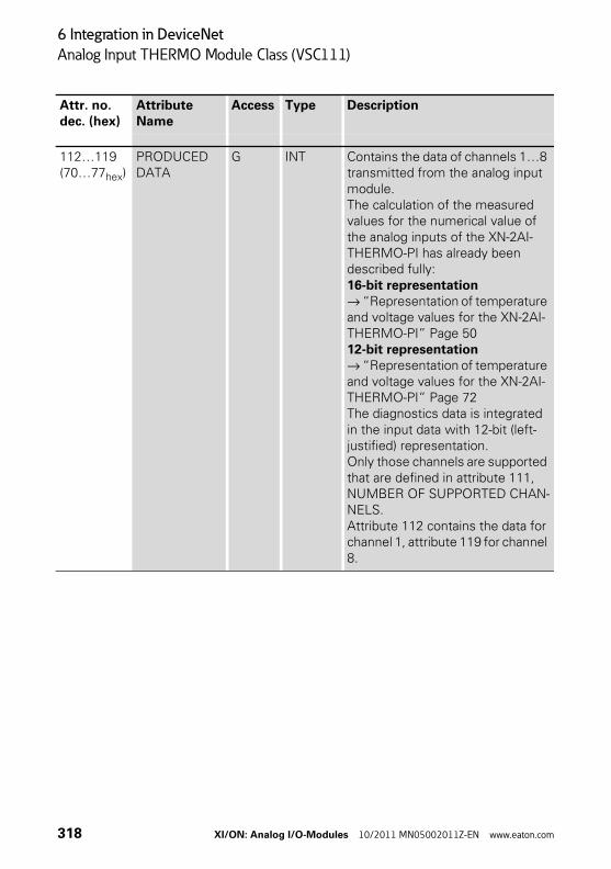
6 Integration in DeviceNet
Analog Input THERMO Module Class (VSC111)
112…119(70…77hex)
PRODUCED DATA
G INT Contains the data of channels 1…8 transmitted from the analog input module.The calculation of the measured values for the numerical value of the analog inputs of the XN-2AI-THERMO-PI has already been described fully: 16-bit representation→ “Representation of temperature and voltage values for the XN-2AI-THERMO-PI” Page 5012-bit representation→ “Representation of temperature and voltage values for the XN-2AI-THERMO-PI” Page 72The diagnostics data is integrated in the input data with 12-bit (left-justified) representation.Only those channels are supported that are defined in attribute 111, NUMBER OF SUPPORTED CHAN-NELS.Attribute 112 contains the data for channel 1, attribute 119 for channel 8.
Attr. no.dec. (hex)
Attribute Name
Access Type Description
318 XI/ON: Analog I/O-Modules 10/2011 MN05002011Z-EN www.eaton.com
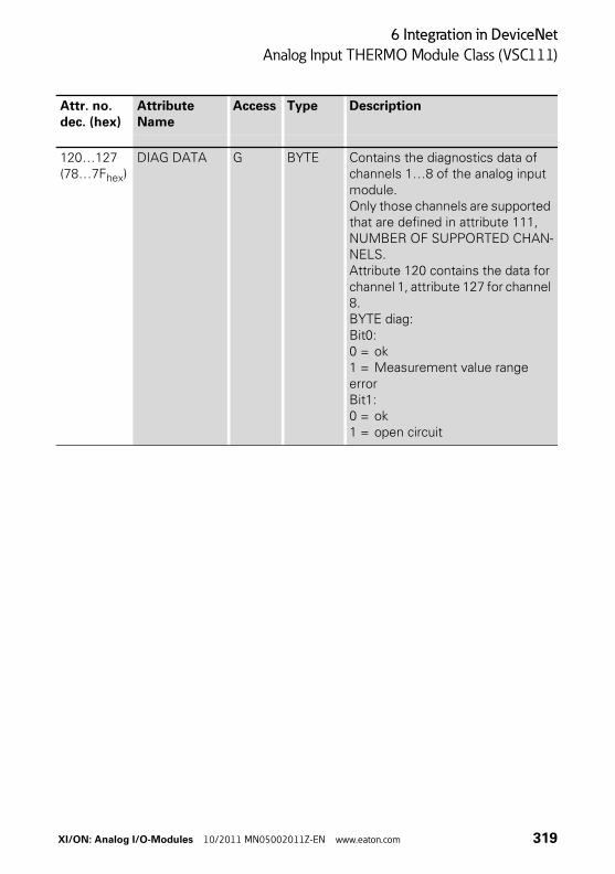
6 Integration in DeviceNet
Analog Input THERMO Module Class (VSC111)
120…127(78…7Fhex)
DIAG DATA G BYTE Contains the diagnostics data of channels 1…8 of the analog input module. Only those channels are supported that are defined in attribute 111, NUMBER OF SUPPORTED CHAN-NELS. Attribute 120 contains the data for channel 1, attribute 127 for channel 8.BYTE diag:Bit0: 0 = ok1 = Measurement value range errorBit1:0 = ok1 = open circuit
Attr. no.dec. (hex)
Attribute Name
Access Type Description
XI/ON: Analog I/O-Modules 10/2011 MN05002011Z-EN www.eaton.com 319
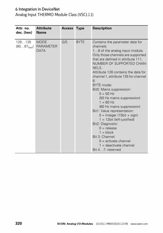
6 Integration in DeviceNet
Analog Input THERMO Module Class (VSC111)
128…135(80…87hex)
MODE PARAMETER DATA
G/S BYTE Contains the parameter data for channels1…8 of the analog input module. Only those channels are supported that are defined in attribute 111, NUMBER OF SUPPORTED CHAN-NELS.Attribute 128 contains the data for channel 1, attribute 135 for channel 8. BYTE mode:Bit0: Mains suppression:
0 = 50 Hz (50 Hz mains suppression)1 = 60 Hz (60 Hz mains suppression)
Bit1: Value representation:0 = Integer (15bit + sign) 1 = 12bit (left-justified)
Bit2: Diagnostic:0 = release1 = block
Bit 3: Channel:0 = activate channel1 = deactivate channel
Bit 4…7: reserved
Attr. no.dec. (hex)
Attribute Name
Access Type Description
320 XI/ON: Analog I/O-Modules 10/2011 MN05002011Z-EN www.eaton.com
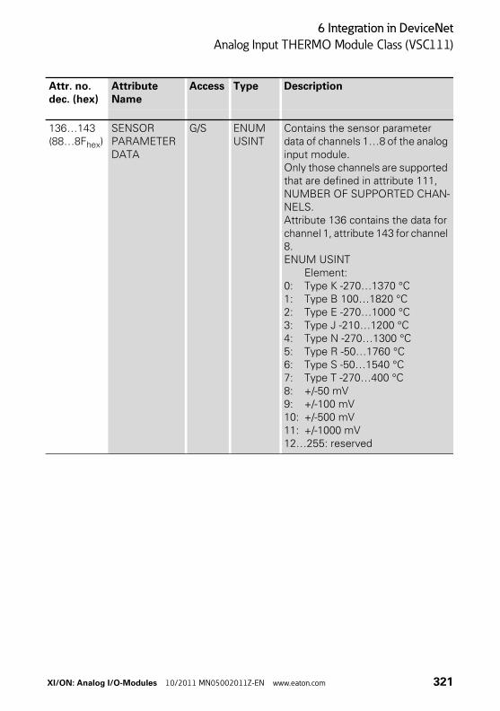
6 Integration in DeviceNet
Analog Input THERMO Module Class (VSC111)
136…143(88…8Fhex)
SENSOR PARAMETER DATA
G/S ENUM USINT
Contains the sensor parameter data of channels 1…8 of the analog input module. Only those channels are supported that are defined in attribute 111, NUMBER OF SUPPORTED CHAN-NELS.Attribute 136 contains the data for channel 1, attribute 143 for channel 8. ENUM USINT
Element:0: Type K -270…1370 °C1: Type B 100…1820 °C2: Type E -270…1000 °C3: Type J -210…1200 °C4: Type N -270…1300 °C5: Type R -50…1760 °C6: Type S -50…1540 °C7: Type T -270…400 °C8: +/-50 mV9: +/-100 mV10: +/-500 mV11: +/-1000 mV12…255: reserved
Attr. no.dec. (hex)
Attribute Name
Access Type Description
XI/ON: Analog I/O-Modules 10/2011 MN05002011Z-EN www.eaton.com 321
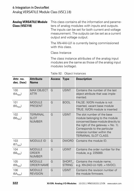
6 Integration in DeviceNet
Analog VERSATILE Module Class (VSC118)
Analog VERSATILE Module Class (VSC118)
This class contains all the information and parame-ters of analog modules with inputs and outputs. The inputs can be set for both current and voltage measurement. The outputs can be set as a current output and voltage output.
The XN-4AI-U/I is currently being commissioned with this class.
Class Instance
The class instance attributes of the analog input modules are the same as those of the analog input modules (voltage).
Table 92: Object Instances
Attr. no.dec. (hex)
Attribute Name
Access Type Description
100(64hex)
MAX OBJECT ATTR
G USINT Contains the number of the last object attribute that was imple-mented.
101(65hex)
MODULE PRESENT
G BOOL FALSE: XI/ON module is not inserted, vacant base moduleTRUE: XI/ON module is inserted
102(66hex)
TERMINAL SLOT NUMBER
G USINT The slot number of the base module belonging to the module concerned (base module directly to the right of the gateway = No. 1). Corresponds to the particular instance number within the TERMINAL SLOT CLASS.
103(67hex)
MODULE ID G DWORD Contains the module ID.
104(68hex)
MODULE ORDER NUMBER
G UDINT Contains the order number for the module, e.g. 225000.
105(69hex)
MODULE ORDER NAME
G SHORT_STRING
Contains the module name, e.g. XN-2AO-U(-10/0..+10VDC).
106(6Ahex)
MODULE REVISION
G USINT Contains the revision number of the module firmware.
322 XI/ON: Analog I/O-Modules 10/2011 MN05002011Z-EN www.eaton.com
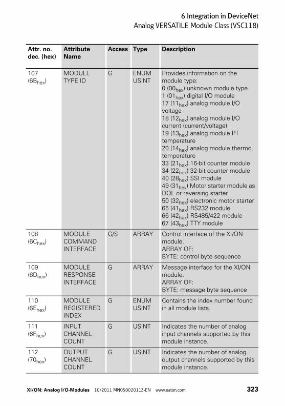
6 Integration in DeviceNet
Analog VERSATILE Module Class (VSC118)
107(6Bhex)
MODULE TYPE ID
G ENUM USINT
Provides information on the module type:0 (00hex) unknown module type1 (01hex) digital I/O module17 (11hex) analog module I/O voltage18 (12hex) analog module I/O current (current/voltage)19 (13hex) analog module PT temperature20 (14hex) analog module thermo temperature33 (21hex) 16-bit counter module34 (22hex) 32-bit counter module40 (28hex) SSI module49 (31hex) Motor starter module as DOL or reversing starter50 (32hex) electronic motor starter65 (41hex) RS232 module66 (42hex) RS485/422 module67 (43hex) TTY module
108(6Chex)
MODULE COMMAND INTERFACE
G/S ARRAY Control interface of the XI/ON module.ARRAY OF:BYTE: control byte sequence
109(6Dhex)
MODULE RESPONSE INTERFACE
G ARRAY Message interface for the XI/ON module.ARRAY OF:BYTE: message byte sequence
110(6Ehex)
MODULE REGISTERED INDEX
G ENUM USINT
Contains the index number found in all module lists.
111(6Fhex)
INPUT CHANNELCOUNT
G USINT Indicates the number of analog input channels supported by this module instance.
112(70hex)
OUTPUT CHANNELCOUNT
G USINT Indicates the number of analog output channels supported by this module instance.
Attr. no.dec. (hex)
Attribute Name
Access Type Description
XI/ON: Analog I/O-Modules 10/2011 MN05002011Z-EN www.eaton.com 323
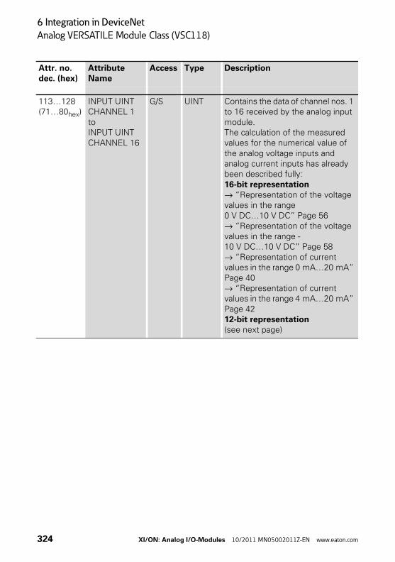
6 Integration in DeviceNet
Analog VERSATILE Module Class (VSC118)
113…128(71…80hex)
INPUT UINT CHANNEL 1toINPUT UINT CHANNEL 16
G/S UINT Contains the data of channel nos. 1 to 16 received by the analog input module.The calculation of the measured values for the numerical value of the analog voltage inputs and analog current inputs has already been described fully: 16-bit representation→ “Representation of the voltage values in the range 0 V DC…10 V DC” Page 56→ “Representation of the voltage values in the range -10 V DC…10 V DC” Page 58→ “Representation of current values in the range 0 mA…20 mA” Page 40→ “Representation of current values in the range 4 mA…20 mA” Page 4212-bit representation(see next page)
Attr. no.dec. (hex)
Attribute Name
Access Type Description
324 XI/ON: Analog I/O-Modules 10/2011 MN05002011Z-EN www.eaton.com
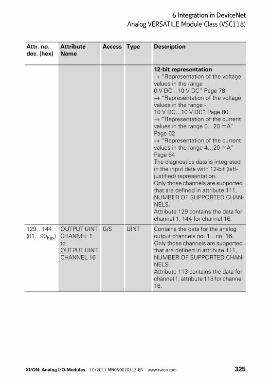
6 Integration in DeviceNet
Analog VERSATILE Module Class (VSC118)
12-bit representation→ “Representation of the voltage values in the range 0 V DC…10 V DC” Page 78→ “Representation of the voltage values in the range -10 V DC…10 V DC” Page 80→ “Representation of the current values in the range 0…20 mA” Page 62→ “Representation of the current values in the range 4…20 mA” Page 64The diagnostics data is integrated in the input data with 12-bit (left-justified) representation.Only those channels are supported that are defined in attribute 111, NUMBER OF SUPPORTED CHAN-NELS.Attribute 129 contains the data for channel 1, 144 for channel 16.
129…144(81…90hex)
OUTPUT UINT CHANNEL 1toOUTPUT UINT CHANNEL 16
G/S UINT Contains the data for the analog output channels no. 1…no. 16.Only those channels are supported that are defined in attribute 111, NUMBER OF SUPPORTED CHAN-NELS.Attribute 113 contains the data for channel 1, attribute 118 for channel 16.
Attr. no.dec. (hex)
Attribute Name
Access Type Description
XI/ON: Analog I/O-Modules 10/2011 MN05002011Z-EN www.eaton.com 325
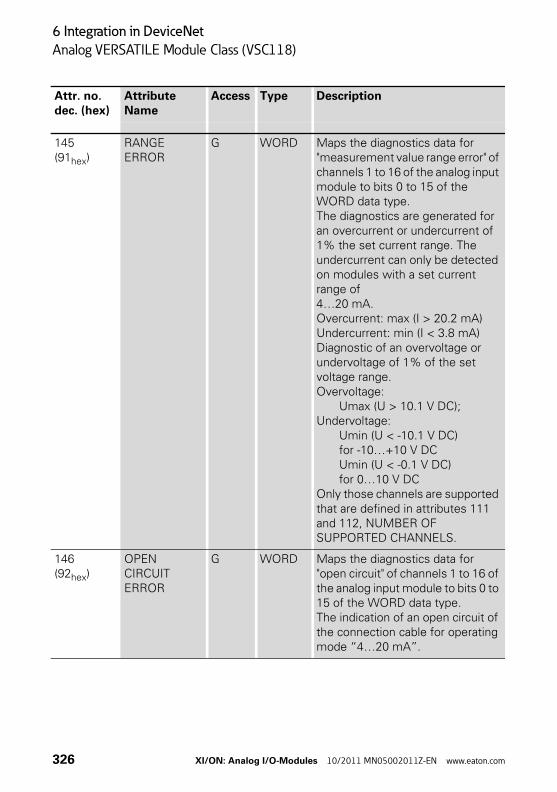
6 Integration in DeviceNet
Analog VERSATILE Module Class (VSC118)
145 (91hex)
RANGE ERROR
G WORD Maps the diagnostics data for "measurement value range error" of channels 1 to 16 of the analog input module to bits 0 to 15 of the WORD data type. The diagnostics are generated for an overcurrent or undercurrent of 1% the set current range. The undercurrent can only be detected on modules with a set current range of 4…20 mA.Overcurrent: max (I > 20.2 mA)Undercurrent: min (I < 3.8 mA)Diagnostic of an overvoltage or undervoltage of 1% of the set voltage range.Overvoltage:
Umax (U > 10.1 V DC);Undervoltage:
Umin (U < -10.1 V DC)for -10…+10 V DCUmin (U < -0.1 V DC)for 0…10 V DC
Only those channels are supported that are defined in attributes 111 and 112, NUMBER OF SUPPORTED CHANNELS.
146 (92hex)
OPENCIRCUIT ERROR
G WORD Maps the diagnostics data for "open circuit" of channels 1 to 16 of the analog input module to bits 0 to 15 of the WORD data type.The indication of an open circuit of the connection cable for operating mode “4…20 mA”.
Attr. no.dec. (hex)
Attribute Name
Access Type Description
326 XI/ON: Analog I/O-Modules 10/2011 MN05002011Z-EN www.eaton.com
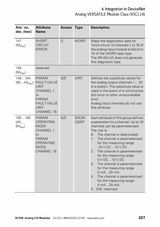
6 Integration in DeviceNet
Analog VERSATILE Module Class (VSC118)
147 (93hex)
SHORT CIRCUIT ERROR
G WORD Maps the diagnostics data for "short-circuit" of channels 1 to 16 of the analog input module to bits 0 to 15 of the WORD data type.The XN-4AI-U/I does not generate this diagnostic type.
148(94hex)
reserved
149…164(94…A4hex)
PARAM FAULT VALUE UINT CHANNEL 1toPARAM FAULT VALUE UINT CHANNEL 16
G/S UINT Defines the substitute values for the analog output channels 1…16 of a station. The substitute value is used in the event of a communica-tion error or other unrecoverable error.Analog input channels do not use this attribute.
165…180(A5…B4hex)
PARAM OPERATING MODE CHANNEL 1toPARAM OPERATING MODE CHANNEL 16
G/S ENUM USINT
Each attribute of this group defines a parameter for a channel. Up to 16 channels can be parameterised.The rule is:0: The channel is deactivated.1: The channel is parameterised
for the measuring range -10 V DC…10 V DC.
2: The channel is parameterised for the measuring range 0 V DC…10 V DC.
3: The channel is parameterised for the measuring range 0 mA…20 mA.
4: The channel is parameterised for the measuring range 4 mA…20 mA.
5…255: reserved
Attr. no.dec. (hex)
Attribute Name
Access Type Description
XI/ON: Analog I/O-Modules 10/2011 MN05002011Z-EN www.eaton.com 327
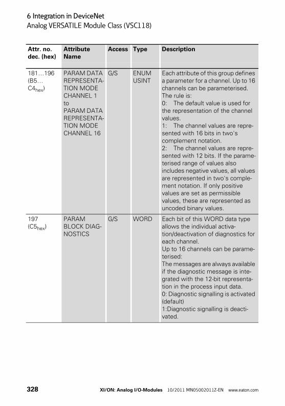
6 Integration in DeviceNet
Analog VERSATILE Module Class (VSC118)
181…196(B5…C4hex)
PARAM DATA REPRESENTA-TION MODE CHANNEL 1toPARAM DATA REPRESENTA-TION MODE CHANNEL 16
G/S ENUM USINT
Each attribute of this group defines a parameter for a channel. Up to 16 channels can be parameterised.The rule is:0: The default value is used for the representation of the channel values.1: The channel values are repre-sented with 16 bits in two's complement notation.2: The channel values are repre-sented with 12 bits. If the parame-terised range of values also includes negative values, all values are represented in two's comple-ment notation. If only positive values are set as permissible values, these are represented as uncoded binary values.
197(C5hex)
PARAM BLOCK DIAG-NOSTICS
G/S WORD Each bit of this WORD data type allows the individual activa-tion/deactivation of diagnostics for each channel.Up to 16 channels can be parame-terised:The messages are always available if the diagnostic message is inte-grated with the 12-bit representa-tion in the process input data.0: Diagnostic signalling is activated (default)1:Diagnostic signalling is deacti-vated.
Attr. no.dec. (hex)
Attribute Name
Access Type Description
328 XI/ON: Analog I/O-Modules 10/2011 MN05002011Z-EN www.eaton.com
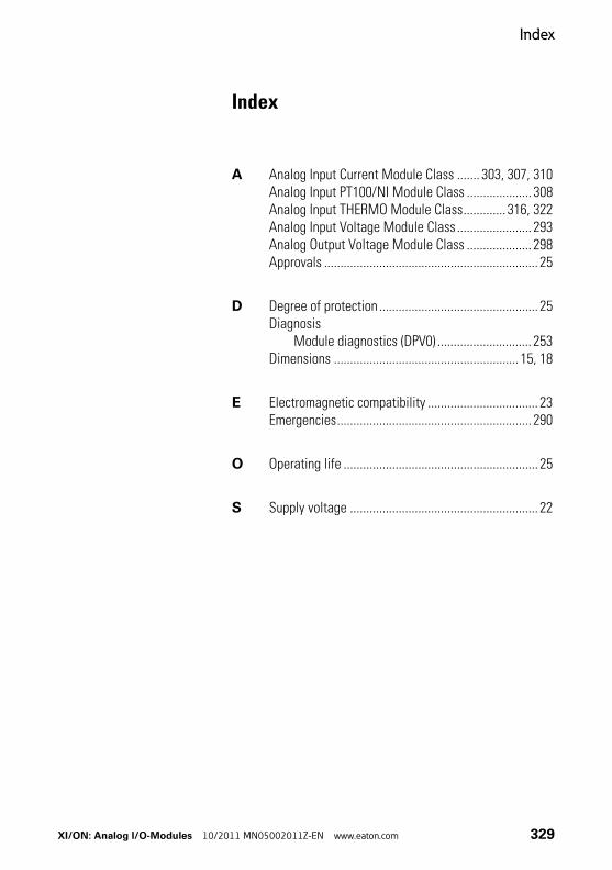
Index
Index
A Analog Input Current Module Class ....... 303, 307, 310Analog Input PT100/NI Module Class .................... 308Analog Input THERMO Module Class............. 316, 322Analog Input Voltage Module Class ....................... 293Analog Output Voltage Module Class .................... 298Approvals .................................................................. 25
D Degree of protection ................................................. 25Diagnosis
Module diagnostics (DPV0) ............................. 253Dimensions ......................................................... 15, 18
E Electromagnetic compatibility .................................. 23Emergencies............................................................ 290
O Operating life ............................................................ 25
S Supply voltage .......................................................... 22
XI/ON: Analog I/O-Modules 10/2011 MN05002011Z-EN www.eaton.com 329

Index
330 XI/ON: Analog I/O-Modules 10/2011 MN05002011Z-EN www.eaton.com