Embed Size (px)
Citation preview
7/31/2019 Yr7 Notes 2003(1)-4
http://slidepdf.com/reader/full/yr7-notes-20031-4 1/18
Light
Luminous and non-luminous objects
Luminous objects give out their own light (e.g. the sun, a lamp, a TV screen, a laser). Objects which wesee due to the light they reflect (e.g. this page) are called non-luminous.
Transmission of light
Different materials allow light to pass through them (transmission) to different extents
Transparent materials Allow all of the light incident on them to pass throughTranslucent materials Allow some of the light incident on them to pass throughOpaque materials Allow none of the light incident on them to pass through (cast shadows)
Light rays
The formation of shadows, images in pinhole cameras and the path of a laser beam are evidence thatlight travels in straight lines.
In diagrams arrowed lines called rays are used to show which way light is going.
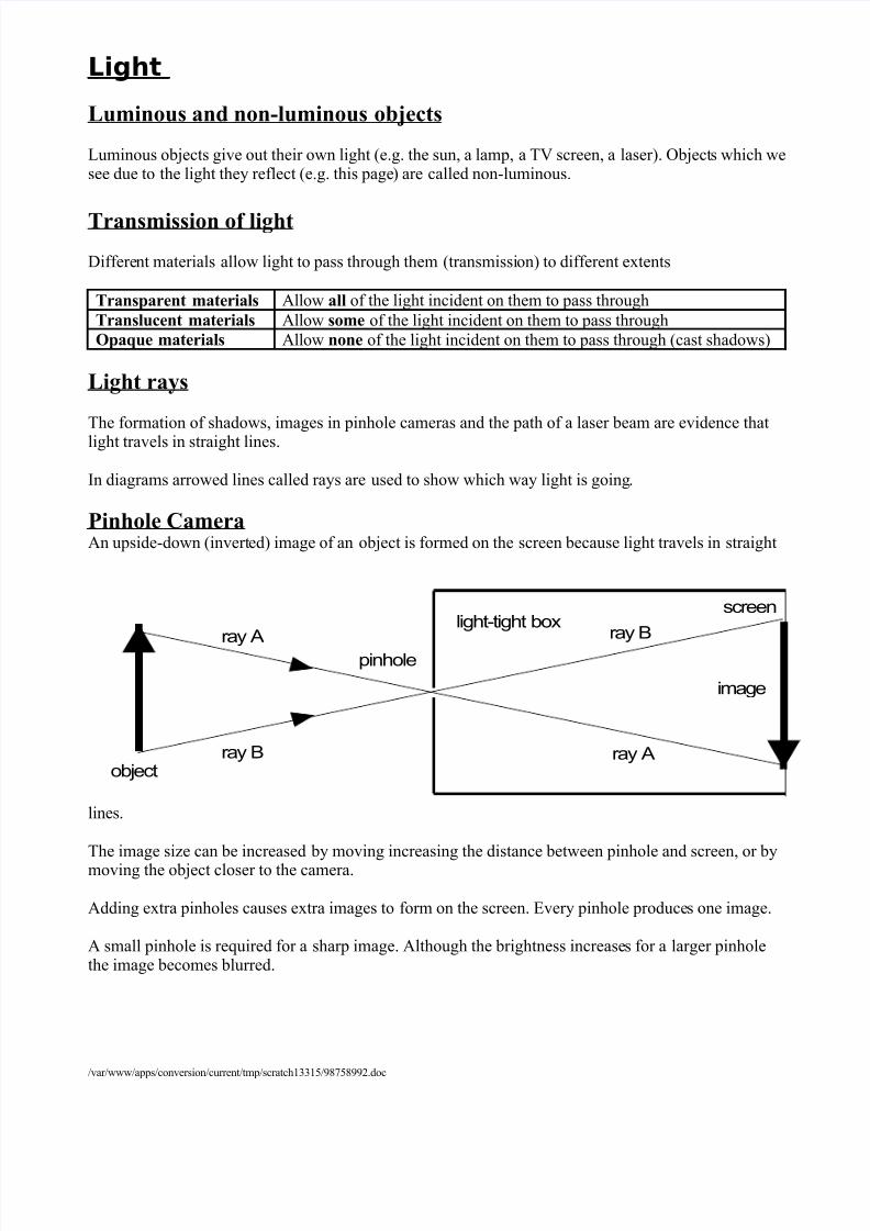
Pinhole CameraAn upside-down (inverted) image of an object is formed on the screen because light travels in straight
lines.
The image size can be increased by moving increasing the distance between pinhole and screen, or bymoving the object closer to the camera.
Adding extra pinholes causes extra images to form on the screen. Every pinhole produces one image.
A small pinhole is required for a sharp image. Although the brightness increases for a larger pinholethe image becomes blurred.
/var/www/apps/conversion/current/tmp/scratch13315/98758992.doc
ray A
ray Aray B
ray B
object
image
pinhole
screenlight-tight box
7/31/2019 Yr7 Notes 2003(1)-4
http://slidepdf.com/reader/full/yr7-notes-20031-4 2/18
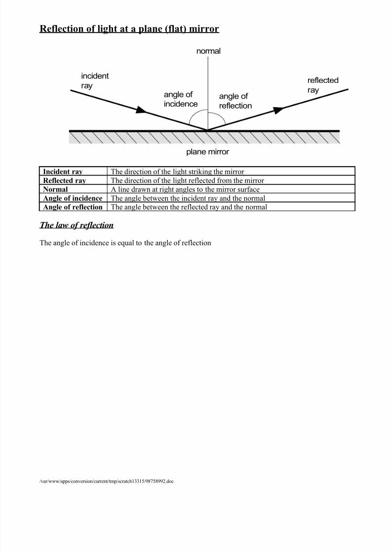
Reflection of light at a plane (flat) mirror
Incident ray The direction of the light striking the mirror Reflected ray The direction of the light reflected from the mirror Normal A line drawn at right angles to the mirror surfaceAngle of incidence The angle between the incident ray and the normalAngle of reflection The angle between the reflected ray and the normal
The law of reflection
The angle of incidence is equal to the angle of reflection
/var/www/apps/conversion/current/tmp/scratch13315/98758992.doc
normal
angle of incidence angle of reflection
incidentray
reflectedray
plane mirror

7/31/2019 Yr7 Notes 2003(1)-4
http://slidepdf.com/reader/full/yr7-notes-20031-4 3/18
The image in a plane mirror
Regular reflection
Because mirrors are smooth and even surfacesall incident rays which are parallel to eachother are reflected parallel to each other. Thisallows a clear image to be formed.
Diffuse reflection
Uneven surfaces cause parallel incident raysto be reflected in a number of differentdirections, a clear image is not formed.
/var/www/apps/conversion/current/tmp/scratch13315/98758992.doc
object ima
observer
The image is laterainverted (back to fr
Angles of incidence areequal to angles of reflection.
90 o90 o
The object and image ar equal distances from themirror.

7/31/2019 Yr7 Notes 2003(1)-4
http://slidepdf.com/reader/full/yr7-notes-20031-4 4/18
Refraction
Light travels at different speeds in different transparent materials.When light passes from one material to another its speed changes and this causes a change in direction.
This is known as refraction.If the incident light is directed along the normal to the boundary between two materials it does notchange direction.The greater the angle of incidence of the incident ray the greater the change in direction of the ray.
Refraction by a prism
A prism is a triangular glass or plastic block.Light emerges from a prism in a different direction to its original direction (the sides of the prism arenot parallel).White light is a mixture of the colours of the continuous visible spectrum (red to violet.)Different colours are refracted by different amounts. Red light is refracted least and violet light themost.A prism splits white light into the colours of the visible spectrum, this is called dispersion.
/var/www/apps/conversion/current/tmp/scratch13315/98758992.doc
glass
partially reflected rayincident ray
refracted ray
emergent ray
normal
normal
air
prism
red
violet
screen
continuousvisiblespectrum
white light

7/31/2019 Yr7 Notes 2003(1)-4
http://slidepdf.com/reader/full/yr7-notes-20031-4 5/18
Colour
The human eye is sensitive to red, green and blue light only. These are the primary colours.
All other colours that we see are due to the amounts of red, green and blue light that make them up.
Secondary colours
Colours we see when two primary colours mixWhite light
Although pure white light is the result of the mixture of all the colours of the visible spectrum, whitelight can also be produced by the mixing of red, green and blue light.
Colour filters
Filters allow only certain colours to pass through them. A red filter transmits red light only, a cyanfilter transmits green and blue light.
/var/www/apps/conversion/current/tmp/scratch13315/98758992.doc
Red
Green Blue
Yellow
Cyan
Magenta
White
w hi te l igh tr e d a n d b lu e lig h t
n o lig
m a g e n t afilter
g r e e nfilter

7/31/2019 Yr7 Notes 2003(1)-4
http://slidepdf.com/reader/full/yr7-notes-20031-4 6/18
Electricity and Magnetism
Electricity
Circuit symbols
Potential difference
The energy which is delivered to an electric circuit comes from the supply. The greater the potentialdifference of the power supply the more energy is delivered. Potential difference is measured in volts,which has the unit symbol V.
Cells in series
The more chemical cells that are connected in series the greater the potential difference that theysupply. The potential difference of a number of cells connected in series is the sum of each cellseparately (bearing in mind the direction in which they are connected.).
/var/www/apps/conversion/current/tmp/scratch13315/98758992.doc
A
7.
8.
9.
10.
11.
switch (open)
switch (closed)
cell
battery
diode
light emitting diode (L.E.D.)
resistor
or filament bulb/lamp
ammeter
light dependent resistor
relay (normally open)
(L.D.R.)N.O.
is equivalent to
1.5V 1.5V 1.5V 4.5V

7/31/2019 Yr7 Notes 2003(1)-4
http://slidepdf.com/reader/full/yr7-notes-20031-4 7/18
Electric current
The energy supplied by the potential difference is delivered to the circuit bythe electric current flowing through the circuit. The current in a metal isactually a flow of electrons (tiny particles that are part of an atom.)
The 1.5V cell supplies enough energy to the current so that it deliversenough energy for the bulb to be normally bright.
Series circuits
All of the current passes through each of the two identical bulbs, theenergy supplied by the 1.5V potential difference is shared by the two
bulbs, they are each less than normally bright.
Parallel circuits
The current splits at the junction in the circuit. The electrons deliver all of their energy to one or other of the bulbs. Both bulbs obtain the full 1.5V
potential difference of the battery, they are each normally bright.
The effects of an electric current
An electric current can cause 1. a heating effect2. a magnetic effect3. a chemical effect
Measurement of electric current
Electric current flowing through a component ismeasured in ampère, A, using an ammeter which isconnected in series with the component.
/var/www/apps/conversion/current/tmp/scratch13315/98758992.doc
1.5 V
current
1.5 V across
the bulb
1.5 V
current
0.75 V0.75 V 1.5 V
1.5 V
1.5 V
A
7/31/2019 Yr7 Notes 2003(1)-4
http://slidepdf.com/reader/full/yr7-notes-20031-4 8/18
Electric current in a series circuit
The electric current at all points in a series circuit isconstant.
Electric current in a parallel circuit
The electric current splits at a junction in a parallelcircuit. The total current through the whole circuit isequal to the sum of the currents in the branches of thecircuit.
Electrical resistance
Electrical components resist the flow of electric current.
The bigger the resistance of an electric component thesmaller the current that is produced by a particular
potential difference, or the bigger the potential differencethat is needed to produce a particular current
/var/www/apps/conversion/current/tmp/scratch13315/98758992.doc

7/31/2019 Yr7 Notes 2003(1)-4
http://slidepdf.com/reader/full/yr7-notes-20031-4 9/18
Electrical Devices
Switches
An open switch is a break in a circuit which prevents currentto flow.
A switch can be normally open or normally closed.
In the circuit shown in figure 1 bulb 1 is lit but not bulb 2.Switch A must be closed for current to flow through either
bulb, but as switch C is open it does not flow through bulb 2.
The table below shows how this circuit would operate for all possible combinations of switch positions. This is known as atruth table for the circuit.
switch A switch B switch C bulb 1 bulb 2
open open open off off open open closed off off open closed open off off open closed closed off off
closed open open off off closed open closed off onclosed closed open on off closed closed closed on on
Single-pole double-throw (s.p.d.t.) switches
A single-pole double-throw switch allows the current to bedirected through one out of two possible routes through acircuit.
Figure 2 shows how such a switch can be used to switch oneither bulb 1 or bulb 2, in this case bulb 1 is lit. If A wasconnected to Y then bulb 2, and not bulb 1, would be lit.
Figure 3 shows how two s.p.d.t. switches are used to allowa bulb to be
switched onor off fromtwodifferent
positions (staircase lighting)
/var/www/apps/conversion/current/tmp/scratch13315/98758992.doc
figure 3

7/31/2019 Yr7 Notes 2003(1)-4
http://slidepdf.com/reader/full/yr7-notes-20031-4 10/18
Diodes
These allow electrical current to flow in one directiononly (indicated by the arrow of the symbol). Diodes aredamaged by high current, they usually have a largeresistor in series with them to protect them.
In figure 4, bulb 2 lights because diode 2 is forward biased. It is in series with bulb 2 and allows current toflow through it.
Bulb 1 does not light because diode 1 is reverse biased. Itis in series with bulb 1 and does not allow current to flowthrough it.
Light Emitting Diode (l.e.d.)
A diode which lights when it allows current to pass. The greater the current passingthrough an l.e.d. the brighter it lights. These act to indicate the flow of electriccurrent in circuits and electronic systems.
Light Dependent Resistor (l.d.r.)
The resistance of a light dependent resistor decreases as theamount of light falling upon it increases.
Figure 5 shows a lightmeter. In dark conditions the resistance of the l.d.r. becomes very high. This means there is not enoughcurrent flowing through the l.e.d. for it to light.
Reed Switches
These are switches which will either open or close when placedin a strong enough magnetic field. They can be used to detect when doors are opened in alarms if thereed switch is mounted on the door frame and a permanent magnet is mounted on the door.
Reed relay
This consists of a coil of wire (solenoid) and a reedswitch. When electric current flows through thesolenoid the magnetic field that it produces closes thereed switch.
They act as simple amplifiers, allowing a small electriccurrent in one circuit to switch on a larger electriccurrent in another circuit.
/var/www/apps/conversion/current/tmp/scratch13315/98758992.doc
figure 5
N.O.lowcurrentcircuit
highcurrentcircuit
solenoidreedswitch
figure 6

7/31/2019 Yr7 Notes 2003(1)-4
http://slidepdf.com/reader/full/yr7-notes-20031-4 11/18

7/31/2019 Yr7 Notes 2003(1)-4
http://slidepdf.com/reader/full/yr7-notes-20031-4 12/18
Day and night
The earth spins on its axis once every 24 hours. The half facing the sun is in daylight, the other half isin night.
/var/www/apps/conversion/current/tmp/scratch13315/98758992.doc
polar axis
path of U.K.as the earthspins
North Pole
South Pole
DAY NIGHT
sunlight
Figure 1
7/31/2019 Yr7 Notes 2003(1)-4
http://slidepdf.com/reader/full/yr7-notes-20031-4 13/18
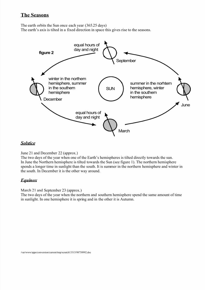
The Seasons
The earth orbits the Sun once each year (365.25 days)The earth’s axis is tilted in a fixed direction in space this gives rise to the seasons.
Solstice
June 21 and December 22 (approx.)The two days of the year when one of the Earth’s hemispheres is tilted directly towards the sun.In June the Northern hemisphere is tilted towards the Sun (see figure 1). The northern hemispherespends a longer time in sunlight than the south. It is summer in the northern hemisphere and winter inthe south. In December it is the other way around.
Equinox
March 21 and September 23 (approx.)The two days of the year when the northern and southern hemisphere spend the same amount of timein sunlight. In one hemisphere it is spring and in the other it is Autumn.
/var/www/apps/conversion/current/tmp/scratch13315/98758992.doc
September
JuneDecember
equal hours of
day and night
equal hours of day and night
winter in the northernhemisphere, summer in the southernhemisphere
summer in the norhternhemisphere, winter in the southernhemisphere
SUN
figure 2
March

7/31/2019 Yr7 Notes 2003(1)-4
http://slidepdf.com/reader/full/yr7-notes-20031-4 14/18
Moons
These are smaller than planets and remain in orbit around planets.
The moon orbits the earth once every 29 days (approximately.)
All of that time one half of the moon is bathed in sunlight but the angle that the moon makes with thesun and earth changes. This alters the amount of the moon we see from earth, we call these changes
phases of the moon.
Each time it orbits the earth the moon also spins once upon it’s own axis, this is why the same side of the moon is always facing us.
Eclipses
/var/www/apps/conversion/current/tmp/scratch13315/98758992.doc
sunlight
1
23
4
5
67
8
earth
moon
1
2
3
4
5
6
7
8
What we see on earth
new moon
waxing crescent
first quarter
waxing gibbous
full moon
waning gibbous
last quarter
waning crescent

7/31/2019 Yr7 Notes 2003(1)-4
http://slidepdf.com/reader/full/yr7-notes-20031-4 15/18
These are rare events caused by the large shadows of the earth and moon.
Solar eclipse
This occurs when the moon comes between the earth and sun blocking out the suns rays.The shadow of the moon consists of a small, central umbra in total darkness and a surrounding region
of partial shadow called the penumbra.
Lunar eclipseWhen the moon moves into the umbra of the Earth’s shadow so that it cannot be seen.
/var/www/apps/conversion/current/tmp/scratch13315/98758992.doc
sun
moon
earth
figure 3
sun mooearth
figure 4

7/31/2019 Yr7 Notes 2003(1)-4
http://slidepdf.com/reader/full/yr7-notes-20031-4 16/18
ForcesA force is a push or pull on an object.The SI unit of force is the newton, N.
Free body diagrams
These show the nature, size and direction of all forces acting on an object.Forces are represented by arrows, the tail of the arrow represents the point where the force is applied.The direction of the arrow represents the direction of the force.The length of the arrow represents the size of the force.
Resultant force
If more than one force acts on an object then the overall force acting is called the resultant force.
Balanced forces
If the resultant of the forces acting on an object is zero then the forces are balanced. Balanced forcescause no change to the movement of an object.If a stationary object is under the action of balanced forces it remains stationary.If a moving object is under the action of balanced forces it continues to move in a straight line alongthe same direction and at the same speed
Effects of balanced forces
1. Stretching 2. Compression 3. Bending
If two equal forces pull inopposite directions on anobject it stretches. It is said to
be in tension.
If two equal forces push inopposite directions on anobject it is compressed or squashed.
Bending is a mixture of tension and compression. Inthe above example the upper half of the beam is stretchedand the lower half compressed.
Plastic and elastic materials
An elastic material is one which will return to its original dimensions (shape) after stretching or compressive forces are removed.A plastic material is permanently deformed by stretching or compressive forces, it does not return toit’s original dimensions.
/var/www/apps/conversion/current/tmp/scratch13315/98758992.doc
7/31/2019 Yr7 Notes 2003(1)-4
http://slidepdf.com/reader/full/yr7-notes-20031-4 17/18
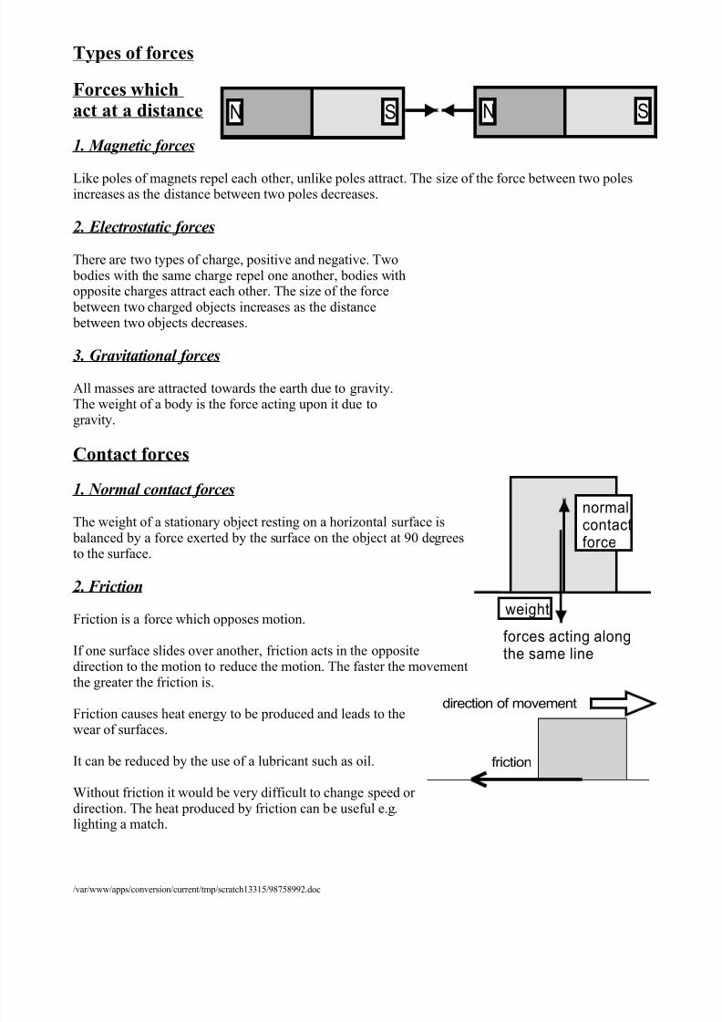
Types of forces Forces whichact at a distance
1. Magnetic forces
Like poles of magnets repel each other, unlike poles attract. The size of the force between two polesincreases as the distance between two poles decreases.
2. Electrostatic forces
There are two types of charge, positive and negative. Two bodies with the same charge repel one another, bodies withopposite charges attract each other. The size of the force
between two charged objects increases as the distance between two objects decreases.
3. Gravitational forcesAll masses are attracted towards the earth due to gravity.The weight of a body is the force acting upon it due togravity.
Contact forces
1. Normal contact forces
The weight of a stationary object resting on a horizontal surface is balanced by a force exerted by the surface on the object at 90 degreesto the surface.
2. Friction
Friction is a force which opposes motion.
If one surface slides over another, friction acts in the oppositedirection to the motion to reduce the motion. The faster the movementthe greater the friction is.
Friction causes heat energy to be produced and leads to thewear of surfaces.
It can be reduced by the use of a lubricant such as oil.
Without friction it would be very difficult to change speed or direction. The heat produced by friction can be useful e.g.lighting a match.
/var/www/apps/conversion/current/tmp/scratch13315/98758992.doc
N SN S
normalcontactforce
weight
forces acting alongthe same line
friction
direction of movement
7/31/2019 Yr7 Notes 2003(1)-4
http://slidepdf.com/reader/full/yr7-notes-20031-4 18/18
3. Viscosity
This is the resistance of a liquid to flow.A viscous liquid (e.g. treacle) causes large frictional forces.
4. Air resistance
A moving object is slowed due to friction with the air, this can be reduced by streamlining.
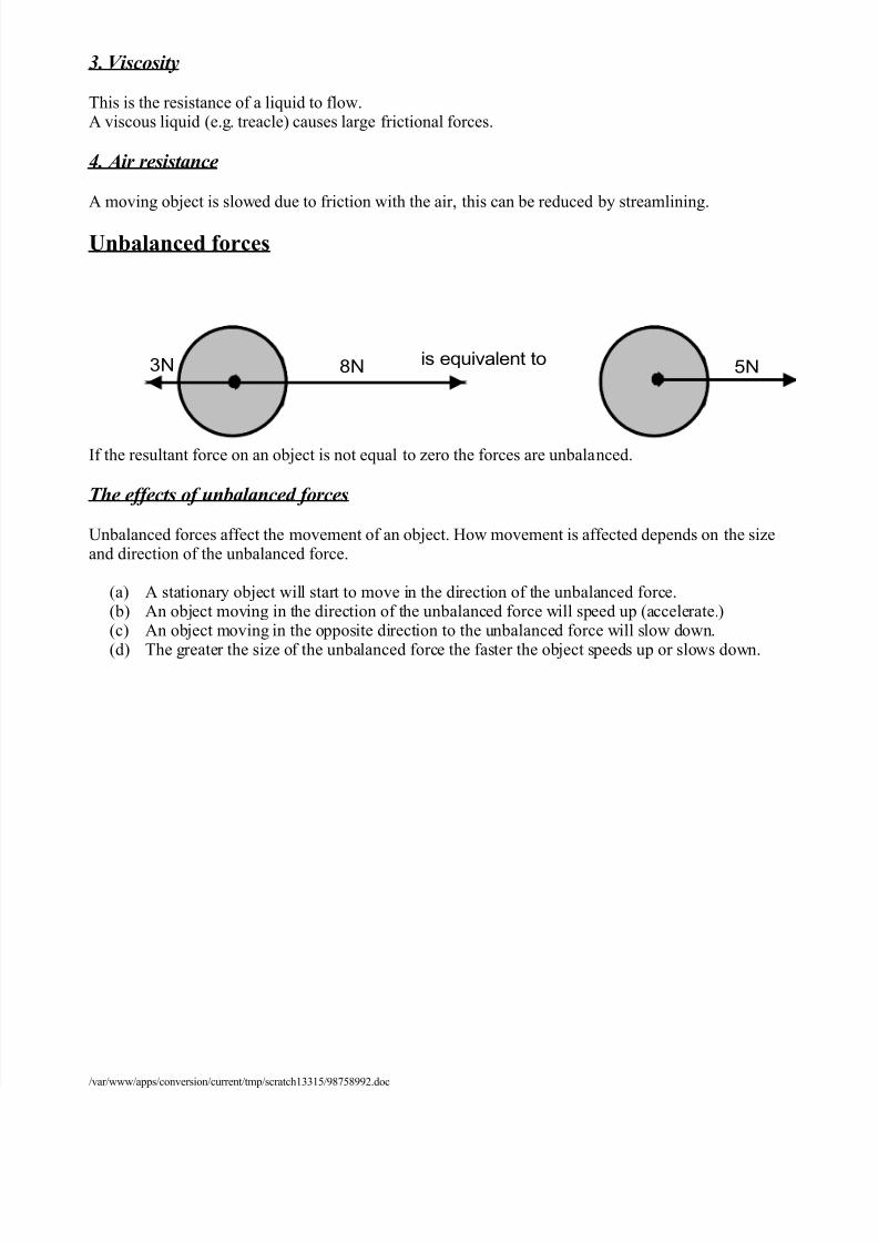
Unbalanced forces
If the resultant force on an object is not equal to zero the forces are unbalanced.
The effects of unbalanced forces
Unbalanced forces affect the movement of an object. How movement is affected depends on the sizeand direction of the unbalanced force.
(a) A stationary object will start to move in the direction of the unbalanced force.(b) An object moving in the direction of the unbalanced force will speed up (accelerate.)(c) An object moving in the opposite direction to the unbalanced force will slow down.
(d) The greater the size of the unbalanced force the faster the object speeds up or slows down.
3N 8N 5Nis equivalent to


![[Economics - Growth] Olivier Blanchard_s Lecture Notes (2003)](https://img.pdfslide.net/doc/110x75/5525e487550346f36e8b4a2d/economics-growth-olivier-blanchards-lecture-notes-2003.jpg)


